Operator's Manual A 1000 -...
62
Edition 4/04 Tamp Applicator A 1000 Operator’s Manual
Transcript of Operator's Manual A 1000 -...

Edition 4/04
Tamp Applicator A 1000
Operator's Manual

cab - Produkttechnik GmbH & Co KG2
A 1000
Gesellschaft fürComputer- und Automations-Bausteine mbH & Co KGcab-Produkttechnik GmbH & Co KGPostfach 19 04 D-76007 KarlsruheWilhelm-Schickard-Str. 14 D-76131 KarlsruheTelefon +49 (0) 721 / 66 26-0Telefax +49 (0) 721 / 66 26-249http://www.cabgmbh.come-mail : [email protected]
copyright by cab / 9008357 / O18 / 1All specifications about delivery, design, performance and weight are given to the best ofour current knowledge and are subject to change without prior notice.
cab - Produkttechnik GmbH & Co KG 3
A 1000
Tamp ApplicatorOperator's ManualTamp Applicator
Operator's Manual
All rights reserved, including those of the translations.
No part of this manual nor any translation may be reproduced or transmitted in anyform or by any means, for any purpose other than the purchaser's personal use,without the express written permission of cab Produkttechnik GmbH & Co KGKarlsruhe.
Edition 4/04Printed in Germany
A 1000

cab - Produkttechnik GmbH & Co KG4
A 1000
Table of ContentsCopyright ......................................................................................................................... 2Table of contents ............................................................................................................. 4
1. Product Description ............................................................................... 6Function .................................................................................................................. 6Important Features ................................................................................................. 7Technical Data ........................................................................................................ 7Tamp Pads ............................................................................................................. 8Blow Pads .............................................................................................................. 9Roll-on Pads ........................................................................................................... 9
2. Delivery Contents ................................................................................. 10
3. General Safety Instructions ..................................................................11
4. Applicator Component Location ......................................................... 12
5. Mounting................................................................................................ 14Mounting the Applicator on the Printer ................................................................ 14Piercing the Universal Tamp Pad ........................................................................ 15Preparing the Applicator for Using a Tamp Pad Type A1312 .............................. 16Mounting the Pad ................................................................................................. 17Mounting the Stopper for the Operation Mode "Blow On" ................................... 18
6. Connections .......................................................................................... 19
7. Printer Configuration............................................................................ 20Standard Method for Changing the Printer Configuration ................................... 20Quick Mode for Adjusting the Delay Times ......................................................... 21Configuration Parameter for the Applicator ......................................................... 22
8. Adjustments .......................................................................................... 268.1.Mechanical Adjustments ...................................................................................... 26
Adjusting the Pad in the Print Direction ............................................................... 26Adjusting the Level and the Sides of the Cylinder Unit ....................................... 27Aligning the Pad to the Dispense Edge ............................................................... 28Opening the Holes on the Blow Tube .................................................................. 28Tuning the Blow Tube .......................................................................................... 29Adjusting the Stopper for the Operation Mode "Blow On" ................................... 30
8.2.Pneumatic Adjustments ....................................................................................... 32Control Valves ...................................................................................................... 32Pressure Reducing Valves ................................................................................... 34Throttle Valves at the Cylinder ............................................................................. 35Throttle Valves at the Manifold ............................................................................ 36
Table of Contents

cab - Produkttechnik GmbH & Co KG 5
A 1000 Table of Contents
9. Operation ............................................................................................... 37Loading Labels and Transfer Ribbon ................................................................... 37Notice about Programming .................................................................................. 37Test Mode Using the Pre-dispense Key without Print Job .................................. 38Test Mode Using the Pre-dispense Key with Print Job ....................................... 39Adjusting the Peel Position .................................................................................. 40Standard Operation .............................................................................................. 41
Appendix A - PLC Interface
Appendix B - Error Messages
Appendix C - Function of the LED of the Electronics
Index
EU - Conformity Declaration

cab - Produkttechnik GmbH & Co KG6
A 1000
1. Product Description
Function
The Tamp Applicator is an optional device to use with the A3/200P,A3/300P, A4/300P and A4/600P printers for automatically applying theprinted label onto the product.
The labels are transfered with a pad, which moves between the twopositions, starting position and labelling position, by a compressed-airdriven pneumatic cylinder.In the starting position, the label is picked up from the printer by thepad. A sensor at the cylinder signals when the pad is in the startingposition. The label is removed from the carrier ribbon directly at thedispense plate of the printer. It is sucked on the pad by a vacuum viadrillings at the bottom of the pad. For support, the label is also blownagainst the pad with an air current coming from a blow tube. Thecorrect transfer of the label is controlled by a vacuum sensor.Next, the pad is moved down into the labelling position, which isconfirmed by another sensor (labelling position sensor). Here, thelabel is transferred onto the product.
The label can be applied with three different methods :
1. Tamp onThe label remains in a fixed position. The label is pressed directlyonto the product.
2. Blow onThe pad moves to a pre-adjusted position approximately 10mmaway from the product. The labels is blown onto the product by anair jet stream. The print and apply cycle performs in a fixedposition or in linear movement of the product.
3. Roll onThe label is dispensed and moved until touching the roller of theroll on pad. At the labelling position the roller is pressed onto theproduct. Then the label is applied and rolled on by the movementof the product.
While the pad is moving back into the starting position, the vacuumsensor checks whether the label has been removed from the pad.
1. Product Description
cab - Produkttechnik GmbH & Co KG 7
A 1000 1. Product Description
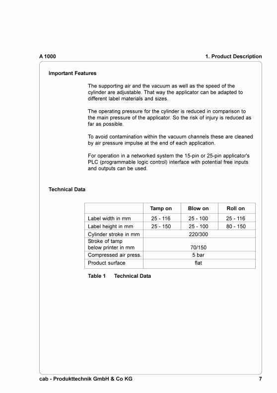
Technical Data
Tamp on Blow on Roll on
Label width in mm 25 - 116 25 - 100 25 - 116
Label height in mm 25 - 150 25 - 100 80 - 150
Cylinder stroke in mm 220/300Stroke of tampbelow printer in mm 70/150
Compressed air press. 5 bar
Product surface flat
Important Features
The supporting air and the vacuum as well as the speed of thecylinder are adjustable. That way the applicator can be adapted todifferent label materials and sizes.
The operating pressure for the cylinder is reduced in comparison tothe main pressure of the applicator. So the risk of injury is reduced asfar as possible.
To avoid contamination within the vacuum channels these are cleanedby air pressure impulse at the end of each application.
For operation in a networked system the 15-pin or 25-pin applicator'sPLC (programmable logic control) interface with potential free inputsand outputs can be used.
Table 1 Technical Data

cab - Produkttechnik GmbH & Co KG8
A 10001. Product Description
Universal tamp pad A1312
Standard size 116x102Standard size 116x152
Fig 1b Universal tamp pad A1312 116x152
Tamp Pads
Universal tamp pads (Type A1112 or Type A1312) are available indifferent standard sizes. At the universal pads the holes in the pad arecovered by a foil. According to the size of the label the holes may bepierced by the customer. For that purpose a piercing pin is included inthe delivery contents.On request, tamp pads customized to the label sized are delivered.
Universal tamp pad A1112
Standard size 70x60Standard size 90x90
Fig.1a Universal tamp pad A1112 70x60

cab - Produkttechnik GmbH & Co KG 9
A 1000 1. Product Description
Fig. 1d Roll-on pad A1411 bxh
Roll-on Pads
Roll-on pads (Type A1411) are only produced on request customizedto the label size.
Fig. 1c Blow pad A2111 bxh
Blow Pads
Blow pads (Type A2111) are only produced on request customized tothe label size.

cab - Produkttechnik GmbH & Co KG10
A 1000
1
Fig. 2 Delivery contents
2. Delivery Contents
1 - Tamp applicator A 1000
2 - Stopper for the operation mode "Blow on"
3 - Pad (as ordered)
4 - Cylinder screw (part of the pad)
5 - Piercing pin (at universal tamp pads only)
43 52
2. Delivery Contents

cab - Produkttechnik GmbH & Co KG 11
A 1000 3. General Safety Instructions
3. General Safety Instructions
CAUTION !Make sure that the printer is disconnected from the power supplyand the shutoff valve at the applicator is closed, while installingthe delivered components.
CAUTION !In operation, moving parts are easily accessible.This applies especially for the sector, where the pad is movedbetween the starting and the labelling position.During operation do not reach into that sector and keep long hair,loose clothes, and jewellery distant.Before any manipulations in those areas, close the shutoff valve.
CAUTION !Do not try to manipulate or repair parts that are not described inthe manuals of the tamp applicator or the printer.

cab - Produkttechnik GmbH & Co KG12
A 1000
1 - Vacuum throttle valve2 - Supporting air throttle valve3 - Main pressure manometer4 - Knurled screw for attaching the applicator to the printer5 - Upper cylinder throttle valve6 - Pneumatic cylinder7 - Cylinder unit8 - Lower cylinder throttle valve9 - Pad holder
10 - Pad (application specific)11 - Blow tube for supporting air
Fig. 4a Front view A 1000
1
2
3
4
5
6
7
8
9
10
11
4. Applicator Component Location
4. Applicator Component Location

cab - Produkttechnik GmbH & Co KG 13
A 1000
1 2 3 4 5 6 7 8 9 10
1 - Blow tube for supporting air2 - Pre-dispense key3 - Knurled screw for attaching the applicator to the printer4 - Interface to the printer5 - Pins6 - 25 pin PLC interface connector7 - 15 pin PLC interface connector8 - Connector for the compressed air9 - Shutoff valve
10 - Service unit
Fig. 4b Rear view A 1000
4. Applicator Component Location

cab - Produkttechnik GmbH & Co KG14
A 1000
21 3 4
5. Mounting
5. Mounting
Mounting the Applicator on the Printer
CAUTION !Make sure that the printer is switched off before mounting theapplicator !
1. Insert the pins on the back of the applicator (2) into the holes (3)of the printer.Press the applicator against the printer. That way the plug of theapplicator will be connected to the peripheral port (4) of the printer.
2. Secure the applicator (2) with the screw (1).
Fig. 5a Mounting the applicator

cab - Produkttechnik GmbH & Co KG 15
A 1000
3
1 2
2 mm
5. Mounting
Piercing the Universal Tamp Pad
On the bottom of the pads there are holes for sucking and holding thelabels by vacuum. When an universal tamp pad is delivered theseholes are covered by a foil and must be opened according to the labelsize. For that purpose a piercing pin is included in the deliverycontents.
Fig. 5b Piercing the sliding foil (holes to be opened are bold)
1. Place a label (1) to be operated on the bottom side of the pad (2).The label must be aligned to the side edge and stand over the rearedge of the pad by 2 mm.
2. Open all the holes, which are certainly covered by the label. Openthe holes completely by turning the piercing pin (3) inside theholes.
CAUTION !Do not open holes, which are located less than 1mm from a labeledge.

cab - Produkttechnik GmbH & Co KG16
A 1000
2
1
3
45
6
5. Mounting
Preparing the Applicator for Using a Tamp Pad Type 1312
Fig. 5c Changing the attachment of the cylinder unit
The cylinder unit (6) can be mounted on the bracket (1) in two differentpositions.When the applicator is delivered, the cylinder unit is mounted on thebracket using the upper threaded hole (4). That position is suitable forthe most pads.If you want to use an universal tamp pad type A1312 the fitting of thecylinder unit must be changed.
1. Loosen the screw (3) with washer (2) and remove the cylinder unitfrom the bracket (1).
2. Fix the cylinder unit with screw (3) and washer (2) by using thelower threaded hole (5).

cab - Produkttechnik GmbH & Co KG 17
A 1000
2
1
4
3
7
5
6
5
5. Mounting
Fig. 5d Mounting the pad
1. Pull the tube (1) out of the push-in-fitting
2. Insert the pin (6) on the pad (7) into the hole on the bottom side ofthe pad holder (4).
3. Fix the pad (7) with the screw (2) at the pad holder (4).
4. Insert the vacuum tube (3) an the blow-air tube into theappropriate push-in-fittings (5) of the pad.
5. Insert the tube (1) into the appropriate push-in-fitting (5) on thecylinder.
CAUTION !To avoid possible collisions of the pad with other parts of theprinter-applicator system, please roughly align the pad in alldirections (see "Mechanical Adjustments") before connecting theapplicator to the compressed air supply !
Mounting the Pad

cab - Produkttechnik GmbH & Co KG18
A 1000
2
4
1
31
3
5. Mounting
Mounting the Stopper for the Operation Mode "Blow On"
The delivery contents of the applicator include a stopper (1). With thisstopper the labelling position for the operation mode "Blow on" can beadjusted.
1. Loosen the screw (3) at the stopper (1).
2. Slide the stopper (1) with the rubber buffer at the bottom side ontothe rods (4).
3. Tighten the screw (3).
For more information on the stopper adjustment see chapter"Mechanical Adjustments".
Fig. 5e Mounting the stopper

cab - Produkttechnik GmbH & Co KG 19
A 1000
6. Connections
Fig. 6 Connections
42 31
6. Connections
1. Prepare the connections to the power supply and to the computeras described in the manual of the printer.
2. To contact the PLC interface use the 15-pin or 25-pin connector(for more details see appendix A).
3. Make sure that the shutoff valve (3) is closed (lever at the valve isturned across the air flow direction).
4. Connect the applicator to the compressed air supply.The connector (2) for the compressed air supply is located at theservice unit. The connector is suitable for a 1/4" coupling plug (1).
5. The air pressure for operating the applicator is pre-adjusted to5 bar. Check the pressure at the manometer of the service unit.Correct the adjustment if necessary :- Pull knurled knob (4) up.- Turn knob to tune required operating pressure of 5 bar.
By turning knob clockwise the pressure rises.- Push knob down.
6. Open the shutoff valve. (3/ lever is turned in the air flow direction)
7. Switch on the power supply of the printer.
CAUTION !The pad will immediately be moved in the starting position !

cab - Produkttechnik GmbH & Co KG20
A 10007. Printer Configuration
7. Printer Configuration
The tamp applicator, with its standard components, can be operated indifferent ways. While the original process stays the same, theoperation mode can be chosen within the printer configuration.The most important setting is the selection between the operationmodes "Stamp on", "Blow on" and "Roll on". Additionally the applicatorhas different application modes concerning the order of printing andapplying within one labelling cycle.
Stamp on Blow on Roll on
Print / Apply x x x
Apply / PrintWaiting position up x x x
Apply / PrintWaiting position down x
Standard Method for Changing the Printer Configuration
NOTICE !Please note the detailed information about the printerconfiguration in der Operator's Manual of the printer !
1. Switch to the Offline Menu by pressing the key.
2. Continue to press the key or the key until you reach the
"Setup" menu. Press the key.
3. The parameters are arranged in a tree like structure. Pressing the key as well as the key will scroll between the secondary
menus. By pressing the key, the selected secondary menu willbe chosen.
Further all operating modes can be adjusted by setting different timedelays.
Table 7a Operation and application modes

cab - Produkttechnik GmbH & Co KG 21
A 1000 7. Printer Configuration
Quick Mode for Adjusting the Delay Times
Beside the standard method for the printer configuration there is aquick mode to adjust the delay times available.
NOTICE !The quick mode settings can be made during operation .The changings affect directly the current print job.
1. Switch to the quick mode by pressing the key and keep itpressed down for at least 2 seconds.
2. The first delay time appears on the display. Adjust the delay timeby pressing the key or the key.
3. To switch between the different delay times press the key.
4. Press the key to leave the quick setup mode. The selecteddelay times are stored in the printer.
4. The parameters for the applicator configuration can be foundunder "Setup" -> "Machine parameters" -> "Applicator".
5. Make the parameter setting as necessary.
6. Press the key several times if necessary to return to the"Online" mode.

cab - Produkttechnik GmbH & Co KG22
A 1000
Table 7b Applicator parameters
Setup
Machine param.
Configuration Parameter for the Applicator
Parameter Meaning
Applicator
Mode of oper. Setting the operation modeDefault : Stamp on
Mode of appl. Setting the application modeDefault : Print-Apply
Waiting position Waiting position of the pad withdispensed labelfor Blow on + Apply-Print onlyDefault : up
Blow time Setting the blow timeParameter only appears in theoperation mode Blow onDefault : 0 ms
Roll-on time Setting the roll-on timeParameter only appears in theoperation mode Roll onDefault : 0 ms
Support delay on Setting the switch-on delay for thesupporting airDefault : 0 ms
Support del. off Setting the switch-off delay for thesupporting airDefault : 270 ms
Delay time Setting the start delayDefault : 0 ms
Lock time Setting the locking timeDefault : 0 ms
Peel position Shift the position of the dispensedlabel relative to the dispense plateDefault : 0,0 mm
Vacuum control Setting of the vacuum controlDefault : EIN
7. Printer Configuration
Selection
Stamp onBlow onRoll on
Print-ApplyAppy-Print
updown
0 ... 2500 msin stepsof 10 ms
0 ... 5000 msin stepsof 10 ms
0 ... 2500 msin stepsof 10 ms
0 ... 2500 msin stepsof 10 ms
0 ... 2500 msin stepsof 10 ms
0 ... 2500 msin stepsof 10 ms
+9,9 ... -9,9 mmin stepsof 0,1 mm
OnOff
cab - Produkttechnik GmbH & Co KG 23
A 1000 7. Printer Configuration
Mode of operation
With that parameter the methods for applying the labels on to theproduct (Tamp, Blow, Roll on) can be selected.
Mode of application
The tamp applicator can be operated in two different ways referringthe order of printing and labelling within one labelling cycle.
"Print/Apply"
The print of a label is released by an external start signal (via PLCinterface). At the same moment the vacuum on the pad as well as thesupporting air from the blow tube are switched on. When the label isprinted and picked up from the carrier ribbon, the supporting air isswitched off. Then the lift cylinder is driven to move the pad downtowards the labelling position. A sensor signals when the labellingposition is reached.Following, the vacuum is switched off and the label is placed onto theproduct.After that, the lift cylinder is driven to move the pad back into thestarting position. Thus, the labelling cycle is finished.
"Apply/Print"
Before starting the cyclic operation the printing and picking up of thefirst label has to be released separately by a special signal via PLCinterface.Thus at the start of the cyclic operation when sending the start signalvia PLC, the first label is already on the pad. The following process issimilar to the mode "Print/Apply", but at the end of the cycle the nextlabel is printed and picked up by the pad. Thus, the labelling cycle isfinished.

cab - Produkttechnik GmbH & Co KG24
A 1000
Waiting position
NOTICE !That parameter is available only when the operation mode "Blowon" and the application mode ''Apply/Print'' are selected.
Waiting position upAt the cyclic operation the pad with the printed label waits in thestarting position near the dispense plate of the printer for the startsignal.
Waiting position downAt the cyclic operation the pad with the printed label waits in thelabelling position for the start signal. So the cycle starts directly withblowing the label on to the product.
Blow time
That parameter is available when the operation mode "Blow on" isselected. The time period can be adjusted, when the blowing air forthe transfer of the label onto the product is switched on.
Roll-on time
That parameter is available when the operation mode "Roll on" isselected. The time period can be adjusted, when the roll-on padremains in the labelling position.
Support delay on
The supporting air from the blow tube is not immediately switched onwhen the print of the label is released but delayed. The air is switchedon, when the label has covered a distance.This delay helps to prevent a turning or swinging at the front of thelabel and, consequently, avoids faults when the label is being pickedup from the printer.
Support delay off
Delayed to the process of the label being picked up, the supporting airis switched off.In many cases, after being picked up by the pad the label edge maystill stick on the carrier ribbon. This may affect the accuracy of thelabel positioning or even cause faults in the labelling. Therefore,switching off the air blow delayed can be useful to separate the labelfrom the carrier ribbon and neatly place the label on the surface of thepad.
7. Printer Configuration

cab - Produkttechnik GmbH & Co KG 25
A 1000
Delay time
The parameter determines the time period between the start signaland the start of the labelling process. This delay makes it possible torelease the start of the process controlled by a sensor, for instance,when a sensor is located within an assembly line in front of thelabelling place.
Lock time
All start signals coming in following the first start signal are ignoredwhen they arrive within the lock time.
Peel position
This parameter allows the adjustment of the presentation position ofthe printed label on the dispense plate. Peel position with the initialoffset value of 0 causes the printed label to be peeled off from theliner leaving approximately a .1 (2mm) wide strip of the label stilladhering to the liner. The amount of label left adhering to the liner canbe altered with this parameter.Positive offset values cause more of the label surface to protrude pastthe dispense plate.In the software an extra peel offset value is available. The offsetvalues from Peel position and from software are added together forexecution. The software value does not replace the Peel positionvalue, but temporarily adjusts it for the current job.
NOTICE !The parameter of the printer configuration should be used for thebasic adjustment to optimize the labelling operation in the testmode using the key and the pre-dispense key (see chapter"Test mode"). Adjustments for the several print jobs should bedone with the software parameter.
Vacuum control
The label transfer from the printer to the applicator is checked by avacuum sensor. If the transfer failes, the sucking holes on the pad willnot be covered by the label. Therefore no vacuum can originate on thepad. Following the error message "Vacuum plate empty" will be shownand the label strip will be fed back.If the parameter "Vacuum control" is disabled, the error treatmentdescribed above will not be carried out. This can be helpful especiallyduring adjustments, because the immediate backfeed will becancelled. That way it is more easy to check the reasons for the faultytransfer.For standard operation enable the vacuum control.

cab - Produkttechnik GmbH & Co KG26
A 1000
3
4
Adjusting the Pad in the Print Direction
8. Adjustments
8.1. Mechanical Adjustments
The mechanical adjustments should be made in two steps.To avoid possible collisions of the pad with other parts of the printer-applicator system, please roughly align the pad in all directions beforeconnecting the applicator to the compressed air supply.The sensitive adjustment to optimize the labelling process must bemade with the compressed air switched on.
The pad (3) can be shifted in the print direction to adjust the distancebetween pad and the dispense edge (4) of the printer.
1. Loosen the screw (1).
2. Shift the cylinder unit including the pad (3) inside the elongatedhole (2).The distance between the pad and the dispense edge should beabout 2mm.
3. Tighten the screw (1).
Fig. 8.1a Adjusting the pad in the print direction
123
8. Adjustments

cab - Produkttechnik GmbH & Co KG 27
A 1000
1
2
3
4
Adjusting the sides
1. Loosen the screw (2).2. Move the cylinder unit sidewards until the dispensed label is
aligned centrally to the pad respectively to the open holes in auniversal pad.
3. Tighten the screw.
Fig 8.1b Adjusting the level and the sides of the cylinder unit
Adjusting the level
1. Loosen the screw (1).2. Move the cylinder unit until in its upper (starting) position the lower
rear edge of the pad is located slightly below the dispense edge ofthe printer. The distance between the pad and the dispense edgeis recommended to be around 1 mm.
3. Tighten the screw.
Fig 8.1c Adjusting the level
8. Adjustments
Adjusting the Level and the Sides of the Cylinder Unit

cab - Produkttechnik GmbH & Co KG28
A 1000
1 2
3
1
2
3
8. Adjustments
1. Loosen the screw (1).
2. Adjust the parallelism between the rear edge of the pad (2) andthe dispense edge (3) by turning the pad.
3. Tighten the screw.
Fig. 8.1d Aligning the pad to the dispense edge
Aligning the Pad to the Dispense Edge
The blow tube (1) for the supporting air is designed for labels with awidth of 120 mm. In regular distances of 15 mm the blow tube has sixholes for the supporting air.When the applicator is delivered only the two inner holes are open.The other four holes are closed by plastic rings (2).To adjust the supporting air to the label width, the plastic rings can beremoved from the holes.Open all holes (3), which affect certainly the area of the label.
Opening the Holes on the Blow Tube
Fig. 8.1e Opening the holes on the blow tube

cab - Produkttechnik GmbH & Co KG 29
A 1000
1 2
3
2
8. Adjustments
Tuning the Blow Tube
Fig. 8.1f Tuning the blow tube I
The blow tube (2) for the supporting air can be rotated around itslongitudinal axis. That way the direction of the support air can beoptimized.
1. Loosen the screw (1).2. Turn the blow tube (2) in that direction, that the air current
supports the sucking of the label by the pad.
NOTICE !For small labels adjust the tube until the air current is aligned tothe dispense edge (3) of the printer. That matches with setting 3or 4 at the scale.With increasing label length the supporting air direction must beadjusted away from the dispense edge to setting 1 at the scale.
3. Tighten the screw (1).
Fig. 8.1g Tuning the blow tube II

cab - Produkttechnik GmbH & Co KG30
A 1000
32
1
5
4
7
6
8. Adjustments
Adjusting the Stopper for the Operation Mode "Blow on"
Fig. 8.1h Adjusting the stopper
NOTICE !Switch off the printer and close the shutoff valve for thecompressed air at the service unit.

cab - Produkttechnik GmbH & Co KG 31
A 1000 8. Adjustments
1. Place a product sample (7) at the labelling point.
2. Loosen the screws (3) enough so that you can move the stopper(2) along the guide bars.
3. Pull the tubes (1,4) out of the push-in-fittings
4. Move the pad manually in the required labelling position.
NOTICE !The distance between the blow pad (6) in the labelling positionand the product surface (7) must not exceed 10 mm.
5. Move the stopper (2) against the guide block (5) and tighten thescrew (3).
6. Insert the tubes (1,4) into the appropriate push-in-fittings on thecylinder.
7. Open the shutoff valve and switch on the printer.

cab - Produkttechnik GmbH & Co KG32
A 1000
1 2
34
1 6
5
7 8 9 10 11
8. Adjustments
8.2. Pneumatic Adjustment
Control Valves
Fig. 8.2a Control valves
For adjusting the applicator, some functions can be released directlyby operating the control valves (3, 4, 5).To reach the control valves, loosen two screws (1) on the front andremove the cover (2).That way, three electric switchable control valves for compressed airbecome accessible. For manual tuning, the valves can also beoperated by integrated keys.
Valve (3) to control the lift cylinder
When the printer is turned on, the pad is kept in the starting position.Switching the valve will move down the pad into the labelling position.Normally the back-switching of the valve is controlled by the signal ofthe labelling position sensor.
NOTICE !A manual release of the valve by pressing the integrated keys isonly possible with the printer switched off !
When the key 6 is pressed, the pad moves down as far as possibleand stays in that position. When operated manually, there is nocontrolling by the labelling position sensor.When the key 7 is pressed, the pad moves up.

cab - Produkttechnik GmbH & Co KG 33
A 1000 8. Adjustments
Double valve (4) to control the blow air
This valve controls the blow air on the pad.In the operation mode "Blow on" the label will be blown on to theproduct by switching on the valve.In the operation modes "Stamp on" and "Roll on" the blow air isswitched on for a short time after each application to avoidcontaminations within the vacuum channels.For all functions described above, both internal valves are switchedon.By pressing the keys 8 or 9 the blow air is only switched on by one ofinternal valves.
Double valve (5) to control vacuum and supporting air
One of the internal valves operates the vacuum nozzle and,consequently, controls the vacuum on the pad for picking up the label.The other valve controls the switch-on of the supporting air at the blowtube.By pressing the key 10 the supporting air is switched on. Pressing thekey 11 activates the vacuum on the pad.

cab - Produkttechnik GmbH & Co KG34
A 1000
1
2
8. Adjustments
Pressure Reducing Valves
Fig. 8.2b Pressure reducing valves
The pneumatic control of the applicator contains two pressurereducing valves (1,2). Using those valves the pressure for the two airchambers of the cylinder can be limited in comparison to the mainpressure.The setting of the valve 1 adjusts the pressure for the upper chamberand affects mainly the downward movement of the pad.Valve 2 limits the pressure for the lower chamber and the speed forthe upward pad movement.
NOTICE !When the applicator is delivered, the pressure reducing valvesare adjusted to 2.5 bar and sealed.That way the pad speeds are limited and the risk of injury isminmized.On the other hand this setting guarantees a certain operationalso when heavy pads are used.
For that reason do not change the settings of the pressurereducing valves !
cab - Produkttechnik GmbH & Co KG 35
A 1000
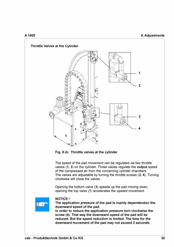
The speed of the pad movement can be regulated via two throttlevalves (1, 3) on the cylinder. Those valves regulate the output speedof the compressed air from the concerning cylinder chambers.The valves are adjustable by turning the throttle screws (2, 4). Turningclockwise will close the valves.
Opening the bottom valve (3) speeds up the pad moving down,opening the top valve (1) accelerates the upward movement.
NOTICE !The application pressure of the pad is mainly dependendon thedownward speed of the pad.In order to reduce the application pressure turn clockwise thescrew (4). That way the downward speed of the pad will bereduced. But the speed reduction is limited. The time for thedownward movement of the pad may not exceed 2 seconds.
1
2
3
4
8. Adjustments
Throttle Valves at the Cylinder
Fig. 8.2c Throttle valves at the cylinder

cab - Produkttechnik GmbH & Co KG36
A 1000
1
2
8. Adjustments
Throttle Valves at the Manifold
Throttle valve (1) to regulate the vacuum
With this valve the vacuum to suck the label onto the pad can beadjusted.Turn the throttle screw to adjust the valve. Turning clockwise will closethe valve.With the vacuum setting the final position of the label on the pad canbe adjusted.
Throttle valve (2) to regulate the supporting air
With this valve the supporting air to blow the label onto the pad can beadjusted.Turn the throttle screw to adjust the valve. Turning clockwise will closethe valve.The valve has to be tuned in such a way, that the label is blown ontothe pad without whirling.
Fig. 8.2d Throttle valves at the manifold

cab - Produkttechnik GmbH & Co KG 37
A 1000 9. Operation
9. Operation
Loading Labels and Transfer Ribbon
Fig. 9a Label and transfer ribbon feed path
1 2
3 4 5
Insert transfer ribbon (1) and labels (2) as shown in figure 9a.For detailled instruction see the Operator's Manual of the printer.
CAUTION !Swing the locking system (4) against the rewind assist roller asshown infigure 9a.Otherwise the pad (3) would collide with the locking system (4)during operation.
Notice about Programming
NOTICE !To operate the applicator the peel-off mode must be activated inthe software !For direct programming use the P-command (see ProgrammingManual)!

cab - Produkttechnik GmbH & Co KG38
A 1000
1
9. Operation
Test Mode Using the Pre-dispense Key without Print Job
The whole labelling process can be simulated without the need of aprint job or a connection to a computer by alternately pressing the
key and the pre-dispense key (1).
NOTICE !Please use that test mode to adjust the parameter "Peel position"in the printer configuration !
If the printer has no print job, pessing the key will release thefeed of a blank label. At the same moment the vacuum at the pad aswell as the supporting air (blow tube) are switched on. After the labelhas been picked up by the pad, the supporting air is switched off.
Pressing the pre-dispense key (1) will drive the lift cylinder to movethe pad down into the labelling position. A sensor signals when thelabelling position is reached.Following, the vacuum is switched off and the label is placed onto theproduct. Then, the lift cylinder is driven to move the pad back into thestarting position.
Fig. 9b Pre-dispense key

cab - Produkttechnik GmbH & Co KG 39
A 1000 9. Operation
Test Mode Using the Pre-dispense Key with Print Job
By pressing the pre-dispense key (1), half cycles of the labellingprocess can alternately be released, provided that there is a print job.
1(st) half cycle
Pressing the key will release the print of one label. At the samemoment the vacuum at the pad as well as the supporting air (blowtube) are switched on. After the label has been printed and picked upby the pad, the supporting air is switched off.
2(nd) half cycle
Pressing the key will drive the lift cylinder to move the pad down intothe labelling position. The sensor signals when the labelling position isreached.Following, the vacuum is switched off and the label is placed onto theproduct. Then, the lift cylinder is driven to move the pad back into thestarting position.
NOTICE !If the label is removed from the pad manually after the first halfcycle of the labelling process, the print process will be repeatedwhen the pre-dispense key is pressed again.

cab - Produkttechnik GmbH & Co KG40
A 10009. Operation
Adjusting the Peel Position
To optimize the taking-over of the labels by the pad there are twodifferent parameters available for adjusting the peel position.
CAUTION !A two-step method to adjust the peel position is described below.It is very important to follow that procedure for a certain startafter label loading and for the re-start after error treatment !
1. Peel position in the printer configuration
First the parameter "Peel position" in the printer configuration must beadjusted (see chapter "Printer Configuration"). That parameter shouldbe used to compensate tolerances between different printers. Thesetting of the parameter will be stored on the printer.Adjust the printer parameter "Peel position" in such a way, that theblank labels are totally peeled-off from the liner. For the adjustmentuse the test mode without print job and simulate the applicationprocess with the key and the pre-dispense key.
2. Peel position in the software
A second peel-off parameter is available in the software. The softwarevalue does not replace the Peel position value of the printerconfiguration, but temporarily adjusts it for the current job.The offset values from Peel position and from software are addedtogether for execution.
NOTICE !Please make sure, that the basic adjustment described abovewas made before adjusting the software peel-off parameter.
Adjust the software parameter with a real print job in such a way, thatthe printed labels are totally peeled-off from the liner.It is recommended to operate the applicator in the test mode with thepre-dispense key.

cab - Produkttechnik GmbH & Co KG 41
A 1000 9. Operation
Standard Operation
1. Check all external connections before starting.
2. Load the material corresponding to the instructions in the chapter"Loading labels and transfer ribbon". Make sure that the lockingsystem is locked.
3. Open the shutoff valve.
4. Switch on the printer.
NOTICE !Make sure that the pad is not covered by a label when switchingon the printer-applicator system.
5. Before starting the first print job, press the key on the printer.This generates a synchronous running. Remove the processedlabels manually. After a few seconds the printer carries out a briefreverse feed and the edge of the next label is positioned at theprint line.This synchronizing also has to be carried out when the print jobhas been interrupted with the key.
NOTICE !Synchronizing is not necessary when the printhead was not liftedbetween print jobs. This also applies if the printer was poweredoff between print jobs.
6. Start a print job.
7. Start the labelling process via PLC interface.
If an error occurs while the applicator is operating, this is shown in thedisplay of the printer (for types of errors and how to treat them seeappendix B).

cab - Produkttechnik GmbH & Co KG42
A 10009. Operation

A - 1cab - Produkttechnik GmbH & Co KG
A 1000 Appendix A - PLC Interface
Appendix A - PLC Interface
For use in a networked system the applicator is equipped with a PLCinterface to start and interrupt the labelling process. It also passes onstate information as well as error messages of the applicator to thesystem control.The interface is placed at the backside of the applicator has a 15 pinas well as a 25 pin SUB-D connector.
NOTICE !The 15 pin connector has the identical pin assignment as the PLCinterfaces of the Apollo an Hermes applicators.
Fig. A-1 PLC interface connectors

A - 2 cab - Produkttechnik GmbH & Co KG
A 1000
Pin Pin Signal Signal Direction Function25 pin 15 pin old *
1 1 E0.1 (+) XSTRT Input Start signal2 2 E0.2 (+) XSTP Input Stop signal (external error)3 3 E0.3 (+) XDREE Input Print first label4 4 A0.1 XDNB Output Printer not ready5 5 A0.2 XEDG Output No existing print job6 6 A0.3 XSAA Output General error message7 7 A0.4 XSOE Output Pad in starting position8 8 GND GND Output Ground (0V) of the printer9 A0.5 XEDST Output Special signal X command10 not used11 E0.5 (-) XRSR Input External RESET (reverse line)12 do not connect13 do not connect14 9 E0.1 (-) XSTRTR Input Start signal (reverse line)15 10 E0.2 (-) XSTPR Input Stop signal (reverse line)16 11 E0.3 (-) XDREER Input Print first label (reverse line)17 12 A0.7 XSUE Output Pad in labelling position18 13 A0.8 XETF Output Applicator fault19 14 COM RÜL Output Common potential (for all outputs)20 15 24V (Out) 24P Output Operating voltage +24V, Si T 100mA21 A0.9 XESP Output Special signal X command22 not used23 E0.5 (+) XRS Input External RESET24 do not connect25 A0.10 /XSOE Output Pad in starting position (inverted)
Tabelle A-1 Pin Assignment of the PLC Interface Connectors* Signal names at Apollo and Hermes applicators
Pin 13
Pin 1
Pin 14
Pin 25
Pin 9
Pin 15Pin 8
Pin 1
Appendix A - PLC Interface
Pin Assignment of the PLC Interface Connectors
Fig. A-2 Pin Assignment of the PLC Interface Connectors

A - 3cab - Produkttechnik GmbH & Co KG
A 1000
Comments on the Signals
NOTICE !The numbers in the brackets concern to the 15 pin connector !
Table A-2 Comments on the signals
Pin Pin Signal Comment25 pin 15 pin
1 1 E0.1 (+) Start signalTo start the cyclic labelling process.
.2 2 E0.2 (+) Stop signal (external error)
The following functions are released- to finish the print of a label and its
picking-up by the pad- to interrupt or to stop the beginning of the
labelling process- to make the pad moving back into the
starting position- to disregard of all following start signals- if activated during the labelling phase, the
display will show the message 'Host stop/error'. (no message during print process)
3 3 E0.3 (+) Print first labelfor application mode "Apply/Print" only :to release the print of the first label andits picking-up by the pad
4 4 A0.1 Printer not readyError message of the printer.The error type is shown on the display.After error correction, the print of the lastlabel will be repeated.
5 5 A0.2 No existing print job. State message.There is no print job currently available.
Activation /active state
Switch on +24Vbetween pin1 andpin14 (9)
Switch on +24Vbetween pin2 andpin15 (10)
Switch on +24Vbetween pin3 andpin16 (11)
Contact betweenpin4 and pin19 (14)is open.
Contact betweenpin5 and pin19 (14)is open.
Appendix A - PLC Interface

A - 4 cab - Produkttechnik GmbH & Co KG
A 1000
Table A-2 Comments on the signals (continuation)
Pin Pin Signal Comment25 pin 15 pin
6 6 A0.3 General error messageGeneral error message of both, printerand applicator.This message is shown when one of thetwo errors either XDNB or XETF occurs.Important in case that only one error signalof the applicator can be analysed from thesystem control.
7 7 A0.4 Pad in starting positionThe pad is in the starting position where itpicks up the label from the printer.
8 8 GND Ground (0V)CAUTION !Pin 8 must not be connected with theground of the PLC. Otherwise thedc decoupling would be lost.
9 A0.5 Special signal x command (bit 0)is controlled by the X command in thedirect programmingfor detailed description of the X commandsee the programming manual
10
11 E0.5 (-) Reverse line of the external RESET signal
12
13
14 9 E0.1 (-) Reverse line of the start signal
Activation /active state
Contact betweenpin6 and pin19 (14)is open.
Contact betweenpin7 and pin19 (14)is open.
if bit 0 is set :Contact betweenpin9 and pin19is closed.
Appendix A - PLC Interface

A - 5cab - Produkttechnik GmbH & Co KG
A 1000
Table A-2 Comments on the signals (continuation)
Pin Pin Signal Comment25 pin 15 pin
15 10 E0.2 (-) Reverse line of the stop signal
16 11 E0.3 (-) Reverse line of the signal "Print first label"
17 12 A0.7 Pad in labelling positionThe pad is in the position where the labelis applied to the product
18 13 A0.8 Applicator faultSignal is active after one of the followingerrors occured :- pad has not reached the labelling positionwithin 2s after the start of the downwardmovement
- pad has not reached the starting positionwithin 2s after the start of the upwardmovement
- a printed label has not been picked up bythe pad properly or it fell down during themovement of the pad (message of thevacuum sensor)
- the label is still on the pad when thepad moves back up (message of thevacuum sensor)
The type of fault is shown in the displayof the printer.After fault correction, the print of the lastlabel printed before the fault occuredwill not be repeated.
19 14 COM Line with common potential for all outputsignals(may be connected with 24V or GND)
Activation /active state
Contact betweenpin17(12) andpin19 (14)is open.
Contact betweenpin18(13) andpin19 (14)is open.
Appendix A - PLC Interface

A - 6 cab - Produkttechnik GmbH & Co KG
A 1000
Table A-2 Comments on the signals (continuation)
Pin Pin Signal Comment25 pin 15 pin
20 15 24V(Out) Operating voltage +24V, Si T 100mAThe applicator system provides anoperation voltage of 24 VCAUTION !You must not apply any externalvoltage on pin 20(15) !The operating voltage allows the use ofthe applicator without being part of anetworked system.Example : To generate the start signal bya foot switch.
21 A0.9 Special signal x command (bit 3)is controlled by the X command in thedirect programmingfor detailed description of the X commandsee the programming manual
22
23 E0.5 (+) External RESETto reset printer and applicator
24
25 A0.10 Pad in starting position (inverted)The pad is in the starting position where itpicks up the label from the printer.
Activation /active state
if bit 3 is set :Contact betweenpin21 and pin19is closed.
Switch on +24Vbetween pin23 andpin11
Contact betweenpin25 and pin19is closed.
Appendix A - PLC Interface

A - 7cab - Produkttechnik GmbH & Co KG
A 1000
Circuit Diagrams of Inputs and Outputs
The inputs are optocouplers with a current limiting resistor of 2.4kΩin the input circuit for an operating voltage of 24V.For each signal [IN (+)] there is a separate reverse line [IN (-)] at theplug connector. From that, the following matching pairs of signalsresult :
Fig. A-3 Circuit of the inputs
Pin1 - E0.1 (+)
Pin14/(9) - E0.1 (-)
Pin2 - E0.2 (+)
Pin15/(10) - E0.2 (-)
Pin3 - E0.3 (+)
Pin16/(11) - E0.3 (-)
Pin23 - E0.5 (+)
Pin11 - E0.5 (-)
Appendix A - PLC Interface

A - 8 cab - Produkttechnik GmbH & Co KG
A 1000
All outputs are realized through solid state relays which outputs areconnected among one another one-sided. The joint line is lead to theplug connector as COM signal.The switch function of the outputs is to open or close the contactbetween the joint line COM and the respective output.
Electrical requirements : Umax
= 42VImax
= 100mAResistance of the closed contact : R
<= 25Ω
Fig. A-4 Circuit of the outputs
Pin4 - A0.1
Pin5 - A0.2
Pin6 - A0.3
Pin7 - A0.4
Pin9 - A0.5
Pin17/(12) - A0.7
Pin19/(14) - COM
Pin18/(13) - A0.8
Pin21 - A0.9
Pin25 - A0.10
Appendix A - PLC Interface
A - 9cab - Produkttechnik GmbH & Co KG
A 1000
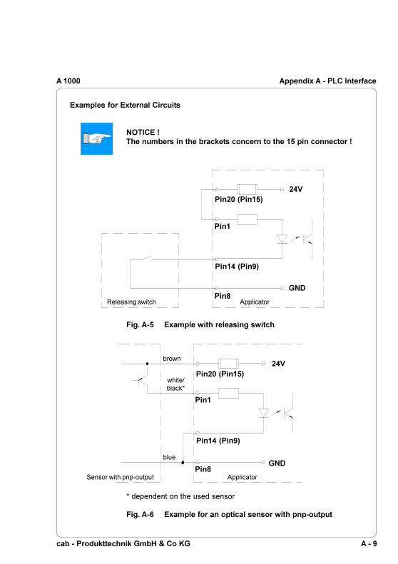
Fig. A-5 Example with releasing switch
Pin1
Pin20 (Pin15)24V
Pin8GND
Releasing switch Applicator
Pin14 (Pin9)
Fig. A-6 Example for an optical sensor with pnp-output
* dependent on the used sensor
Pin1
24V
Pin8GND
blue
white/black*
brown
Sensor with pnp-output Applicator
Pin20 (Pin15)
Pin14 (Pin9)
Appendix A - PLC Interface
Examples for External Circuits
NOTICE !The numbers in the brackets concern to the 15 pin connector !
A - 10 cab - Produkttechnik GmbH & Co KG
A 1000Appendix A - PLC Interface
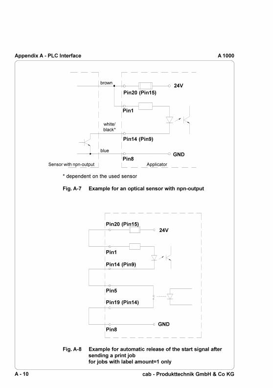
Fig. A-7 Example for an optical sensor with npn-output
* dependent on the used sensor
Pin1
24V
Pin8GND
blue
brown
Sensor with npn-output Applicator
white/black*
Pin14 (Pin9)
Pin20 (Pin15)
Fig. A-8 Example for automatic release of the start signal aftersending a print jobfor jobs with label amount=1 only
Pin1
24V
Pin8GND
Pin14 (Pin9)
Pin20 (Pin15)
Pin19 (Pin14)
Pin5
A - 11cab - Produkttechnik GmbH & Co KG
A 1000 Appendix A - PLC Interface
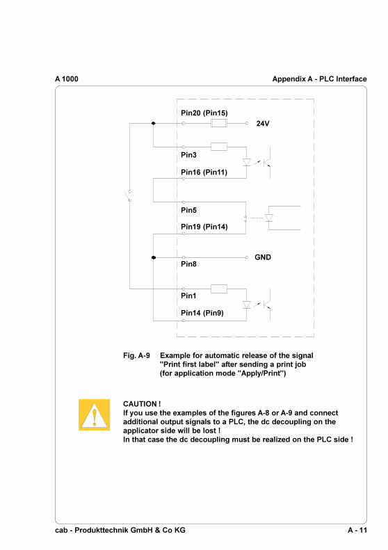
Fig. A-9 Example for automatic release of the signal"Print first label" after sending a print job(for application mode "Apply/Print")
Pin3
24V
Pin8GND
Pin16 (Pin11)
Pin20 (Pin15)
Pin19 (Pin14)
Pin5
CAUTION !If you use the examples of the figures A-8 or A-9 and connectadditional output signals to a PLC, the dc decoupling on theapplicator side will be lost !In that case the dc decoupling must be realized on the PLC side !
Pin1
Pin14 (Pin9)
A - 12 cab - Produkttechnik GmbH & Co KG
A 1000Appendix A - PLC Interface

B - 1cab - Produkttechnik GmbH & Co KG
A 1000 Appendix B - Error Messages
Appendix B - Error Messages
Error Messages of the Printer
Detailed information about printer errors (e.g. 'Paper out', 'Ribbon out',etc.), their causes and correction methods can be found in theOperator's manual for the printer (Appendix C).
NOTICE !With the installation of an applicator the error treatment expands.This means in particular, that after correcting the error and beforethe correction is quit with the key, an additional label feedhas to be released using the key.
This synchronizes the process of printing and labelling. Possiblydispensed blank labels have to be removed manually.After quitting the error message the label caused the error will beprinted once more.
Error Messages of the Applicator
The following table gives an overview of error messages and theirpossible causes. It also suggests methods to resolve the problem.After error correction, always quit the error message of the applicator
with the key.To reprint the label where the applicator error occurred, a new print jobhas to be released.
Resuming the Operation in the Application Mode "Apply/Print"
In the application mode "Apply/Print" a printed label must be picked bythe pad before starting the cyclic operation.Therefore after an error first the signal "Print first label" must be sentor the pre-dispense key must be pressed before the cyclic operationcan be started.

B - 2 cab - Produkttechnik GmbH & Co KG
A 1000Appendix B - Error Messages
Possible cause
Compressed air is switched off.
Labelling process has beenInterrupted by an stop signal viaPLC interface
Label has not been placed ontothe product; after the pad hasmoved back the label still stickson the pad
Pad has not reached the labellingposition within 2s after themovement of the pad
There has been no change of theswitch state at the upper controlsensor (at the cylinder) betweenthe start of the labelling processand the signal from the labellingposition sensor
Pad has not reached the startingposition within 2s after the padhas moved back; or pad has leftstarting position unauthorized
Label has not been picked upproperly by the pad; or label fell offthe pad before it could be placedonto the product
Fehlerbehandlung
Check the shutoff valve
Label the product manually ifnecessary
Label the product manually
Check the pneumaticadjustments (esp. the lowerthrottle valve of the cylinder);Check the applicator forheaviness of its mechanics;Check the labelling positionsensor (service);Label the product manually
Check the sensor (service)
Check the pneumaticadjustments (esp. the upperthe throttle valve of thecylinder);Label the product manually
If possible, place the 'lost' labelonto the product manually;Otherwise stop print job andstart again with adaptedparameters (e.g. count)
Error Message
Air pressure ins.
Host stop/ error
Label not depos.
Lower position
Refl. sensor blk.
Upper position
Vac. plate empty
Table B-1 Error Messages of the Applicator

C - 1cab - Produkttechnik GmbH & Co KG
A 1000 Appendix C - Function of the LEDs of the Electronics
Fig. C-1 LED's on the Applicator Control PCB
LED No. Colour Function Active state
1 yellow Label on the pad On2 yellow Operating voltage 5 V On3 green PLC signal XSTRT On4 green PLC signal XSTP On5 green PLC signal XDREE On6 green PLC signal XRS On7 green not used
Table C-1 LED's on the Applicator Control PCB
Appendix C - Function of the LEDs of the Electronics
PCB Applicator Control

C - 2 cab - Produkttechnik GmbH & Co KG
A 1000Appendix C - Function of the LEDs of the Electronics

cab - Produkttechnik GmbH & Co KG
A 1000
Index
AAir pressure ins. B-2Air pressure 7, 19Applicator fault A-2, A-5Apply/Print 20, 22ff.
BBlowing air tube 17Blowing air 24, 33Blow on 6f., 18, 20, 22ff., 33Blow pad 6, 9Blow time 22, 24Blow tube 6, 12, 28f., 38f.
CCANCEL key (printer) 41Connections 19, 41Connector for compressed air 13,19Control valves 32Cover 32, 34Cylinder unit 12, 16, 26f.
DDelay time (start) 22, 25Delay times 21, 25Delivery contents 10Dispense edge 6, 26ff
EError 41Error messages B-1f.Error messages applicator B-1f.Error messages printer B-1
FFEED key (printer) 25, 38f., B-1
GGeneral error message A-2, A-4
HHost stop / error A-3, B-2
KKeys (control valves) 32f.
LLabelling position 6, 18, 23f., 32,
38f., A-2, A-5Labelling position sensor 6, 23, 32,
38f.Label not depos. B-2Label on the pad C-1LED C-1Level adjustment 27Lock time 22, 25Lower position 32, B-2
MManifold 36Manometer 12, 19MODE key (printer) 20f.
NNo existing print job A-2f.
OOperating pressure 7, 19Operating voltage A-2, A-6, C-1Operation mode 20, 22ff.
Index

cab - Produkttechnik GmbH & Co KG
A 1000
PPad in labelling position A2, A-5Pad in starting position A-2, A-4PAUSE key (printer) B-1PCB Applicator control C-1Peel-off mode 37Peel position 22, 25, 38ff.Peripheral port 14Piercing pin 10, 15Pin assignment of the PLC interface
A-2ff.PLC 41PLC interface 7, 13, 19, A-1ff.Pneumatic cylinder 6, 12Pre-dispense key 13, 25, 38f.Pressure reducing valves 30Print/Apply 20, 22f.Printer configuration 20ff.Printer not ready A-2f.Print first label A-2f.
QQuick mode for adjusting delay
times 21
RRefl. sensor blk. B-2RESET A-2, A-6Roll on 6f., 20, 22ff., 33Roll-on pad 6, 9, 24Roll-on time 22, 24
SSafety instructions 11Service unit 11, 13, 19, 30Shutoff valve 11, 13, 19, 31, 41, B-2Side adjustement 27Signals (PLC) A-1ff., C-1Special signal A-2, A-4, A-6Speed of the pad movement 7, 35Stamp on 20, 22f., 33Starting position 6, 19, 32, 38f.
Index
Start signal A-2f.Stopper 10, 18, 30Stop signal A-2f.Supporting air 6f., 22, 24, 28f., 33, 36,
38f.Switch-off delay supporting air 22, 24Switch-on delay supporting air 22, 24Synchronizing 41
TTamp on 6f.Tamp pad 6, 8Technical data 7Test mode 38f.Throttle valves 12, 35f.
UUniversal tamp pad 8, 10, 12, 15f.Upper position 32, B-2
VVacuum 6f., 15, 23, 33, 36, 38f.Vacuum control 22, 25Vacuum nozzle 33Vacuum plate empty B-2Vacuum sensor 6, 25Vacuum tube 17
WWaiting position 20, 22, 24

cab - Produkttechnik GmbH & Co KG
A 1000
We declare herewith that as a result of the manner in which the machine designatedbelow was designed, the type of construction and the machines which, as a result havebeen brought on to the general market comply with the relevant fundamentalregulations of the EU Rules for Safety and Health. In the event of any alteration whichhas not been approved by us being made to any machine as designated below, thisstatement shall thereby be made invalid.
Description Type:Applicator Tamp Applicator A1000
Applied EU Regulations and Norms:
- EC Machinery Regulations 98/37/EU- Machine Safety EN ISO 12100-1:2003
EN ISO 12100-2:2003
- EC Low Voltage Regulations 73/23/EEC- Data and Office Machine Safety EN 60950-1:2001
- EC Electromagnetic Compatibility Regulations 89/336/EEC- Threshold values for the Interference EN 55022:1998
of Data Machines- Limits for harmonic current emission EN 61000-3-2:2000- Limits of voltage fluctuation and flicker EN 61000-3-3:1995+A1:2001- Immunity characteristics- EN 55024:1998
Limits and methods of measurement- Immunity for industrial environments EN 61000-6-2:2001
Gesellschaft für Computer-und Automations-Bausteine mbH & Co KGWilhelm-Schickard-Straße 14D-76131 Karlsruhe
EU - Conformity Declaration
Signed for, and on behalf of, the Manufacturer :
cab Produkttechnik SömmerdaGesellschaft für Computer-und Automationsbausteine mbH99610 Sömmerda
Sömmerda, 15.04.04
Erwin FascherManaging Director

cab - Produkttechnik GmbH & Co KG
A 1000