OPERATOR’S MANUAL 4000 SERIES SINGLE AUGER MODELS … · OPERATOR’S MANUAL 4000 SERIES SINGLE...
53
“Putting the ‘Total’ into TMR” JAY-LOR ® Fabricating Inc. RR # 2 Orton, Ontario, L0N 1N0 Tel: (519) 787-9353 Fax: (519) 787-7053 OPERATOR’S MANUAL 4000 SERIES SINGLE AUGER MODELS
Transcript of OPERATOR’S MANUAL 4000 SERIES SINGLE AUGER MODELS … · OPERATOR’S MANUAL 4000 SERIES SINGLE...

“Putting the ‘Total’ into TMR”
JAY-LOR® Fabricating Inc. RR # 2 Orton, Ontario, L0N 1N0 Tel: (519) 787-9353 Fax: (519) 787-7053
OPERATOR’S MANUAL
4000 SERIES SINGLE AUGER MODELS
AAA-055-00012
JAY•LOR® Operator’s Manual - 1 - Trailer Units
Introduction .................................................................................................................................................. 3
Policy Statement ........................................................................................................................................... 3
Owner/Operator’s Responsibility ............................................................................................................... 3
Limited Warranty ........................................................................................................................................ 4
Contact Information..................................................................................................................................... 5
Serial Number Locations ............................................................................................................................. 5
Customer Reference INformation............................................................................................................... 6
Safety ............................................................................................................................................................. 7 Safety Alert Symbol ................................................................................................................................... 7 Understand Signal Words........................................................................................................................... 7 Safety Guidelines........................................................................................................................................ 8 General Safety ............................................................................................................................................ 8 Operating Safety......................................................................................................................................... 9 Maintenance Safety .................................................................................................................................. 10 Hydraulic Safety....................................................................................................................................... 10 Tire Safety ................................................................................................................................................ 11 Transport Safety ....................................................................................................................................... 11 Storage Safety........................................................................................................................................... 11 Safety Signs.............................................................................................................................................. 12 How to Install Safety Signs ...................................................................................................................... 12
Sign-Off Form............................................................................................................................................. 12
Safety Sign Locations ................................................................................................................................. 14
Operation .................................................................................................................................................... 18
Machine Components................................................................................................................................. 18
Pre-Operation Checklist ............................................................................................................................ 20
Breaking-In ................................................................................................................................................. 20
Equipment Matching.................................................................................................................................. 21
Controls ....................................................................................................................................................... 23 Weighing .................................................................................................................................................. 23 Restrictor Blades ...................................................................................................................................... 26
Attaching/Unhooking ................................................................................................................................. 26
Shear Bolt Protected Driveline.................................................................................................................. 28
Front Door Discharge Configurations ...................................................................................................... 29 Front Door Discharge ............................................................................................................................... 29

AAA-055-00012
JAY•LOR® Operator’s Manual - 2 - Trailer Units
Unloading Conveyor ................................................................................................................................ 29 Dual Discharge – 8’ (96”) or 9’-2” (110”) Conveyors ............................................................................. 31 Right/Left Discharge – 6’ Flat w/ Height Adjustable Wing Conveyor .................................................... 31
Rear Door Discharge Configurations ....................................................................................................... 33
Gearbox Lubrication.................................................................................................................................. 34
Field Operation........................................................................................................................................... 35 General ..................................................................................................................................................... 35 Cutting and Mixing Procedures................................................................................................................ 36 Unloading Procedures .............................................................................................................................. 37 Operating Hints ........................................................................................................................................ 39
Transporting ............................................................................................................................................... 40
Storage......................................................................................................................................................... 41
Troubleshooting.......................................................................................................................................... 42 General Troubleshooting .......................................................................................................................... 42 Driveline Troubleshooting........................................................................................................................ 43
Standard Model Specifications.................................................................................................................. 48 4350 Trailer Cutter-Mixer-Feeder ............................................................................................................ 48 4405 Trailer Cutter-Mixer-Feeder ............................................................................................................ 49 4425 Trailer Cutter-Mixer-Feeder ............................................................................................................ 50 4575 Trailer Cutter-Mixer-Feeder ............................................................................................................ 51
Drum Extension Installation (If Applicable)............................................................................................ 52
AAA-055-00012
JAY•LOR® Operator’s Manual - 3 - Trailer Units
INTRODUCTION Congratulations on your choice of a JAY•LOR® Cutter-Mixer-Feeder to complement your operation. This equipment has been designed and manufactured to meet the needs of the discriminating buyer for efficient cutting, mixing and feeding. Safe, efficient and trouble free operation of your mixer requires that you and anyone else who will be operating or maintaining the machine, read and understand the Safety, Operation, Maintenance and Troubleshooting information contained within the Operator's Manual. This manual covers the 4000 Series Single Auger Models manufactured by JAY•LOR®. Keep this manual readily available for reference and be sure to pass it on to new Operators or Owners. Contact your nearest JAY•LOR® Dealer or Distributor if you need assistance or information. OPERATOR ORIENTATION - The directions left, right, front, and rear, as mentioned throughout the manual, are as seen from the tractor driver’s seat and facing forward.
POLICY STATEMENT It is the policy of JAY•LOR® to improve its products where it is possible and practical to do so. JAY•LOR® reserves the right to make changes or improvements in design and construction at any time, without incurring the obligation to make these changes on previously manufactured units.
OWNER/OPERATOR’S RESPONSIBILITY It is the Owner/Operator’s responsibility to read the Operator’s Manual, to operate, lubricate, maintain, and store the product in accordance with all instructions and safety procedures. Failure of the operator to read the Operator’s Manual is a misuse of this equipment. Like all mechanical products, JAY•LOR® products will require cleaning and upkeep. It is the Owner/Operator’s responsibility to inspect the product and to have any part(s) and/or assemblies repaired or replaced when continued operation would cause damage or excessive wear to other components or cause a safety hazard. It is the Owner/Operator’s responsibility to deliver the product to the authorized JAY•LOR® Dealer or Distributor, from whom it was purchased, for service or replacement of defective parts which are covered by warranty. Repairs to be submitted for warranty consideration must be made within thirty (30) days of failure. It is the Owner/Operator’s responsibility for any cost incurred by the Dealer for traveling to or hauling of the product for the purpose of performing a warranty obligation or inspection.

AAA-055-00012
JAY•LOR® Operator’s Manual - 4 - Trailer Units
LIMITED WARRANTY JAY•LOR® FABRICATING INC. (the Seller) warrants the articles and units sold to be free from defects in material and workmanship and to conform to applicable specifications. These express warranties are the sole warranties of the Seller, and any other warranties, express, implied in law or implied in fact, are hereby specifically excluded. Refer to the Operator’s Manual content for any applicable warranties expressed otherwise. Seller’s sole obligation under its warranties will be, at its option, to repair or replace any article or part thereof which is proved to be other than warranted. Obligation under this warranty will be limited to replacement or repair of parts found, upon Seller’s inspection, to be defective. All warranties shall expire 12 months from the date the unit or article is placed in service, or 12 months from the date the article or unit is delivered by the Seller, whichever expires first. NO ALLOWANCES WILL BE MADE TO THE BUYER FOR ANY TRANSPORTATION, LABOUR CHARGES, PARTS ADJUSTMENTS OR REPAIRS, OR ANY OTHER WORK, UNLESS THESE CHARGES ARE AUTHORIZED IN ADVANCE BY THE SELLER. The Seller shall in no event be liable for special or consequential damages. If an article is claimed to be defective in material or workmanship, or does not conform to specifications, the Seller, upon notice promptly given, will either examine the article or unit at its site, or issue shipping instructions to return to the Seller. The warranties shall not extend to any articles, units, or parts thereof which have been installed, used, or serviced, otherwise than in conformance with the Seller’s applicable instructions, manuals, service bulletins, or, if none, which shall have been articles, units, parts thereof furnished by the Buyer or acquired from others at the Buyer’s request and/or Buyer’s specifications. The warranties are not applicable for expenses either direct or consequential that may arise from the use or inability to use the articles and units sold by the Seller. The Seller shall in no event be responsible for and will not be held liable for losses, injury, or damage caused to persons or property by reason of operation of Seller’s products or their failure. This warranty does not cover parts and accessories that are under separate guarantees from the manufacturers and service can be obtained from their service facilities in USA and Canada. No warranty is extended to regular service items such as fluid, paint, tires, knives and the like. This warranty pertains to components manufactured or installed by JAY•LOR® Fabricating Inc. only. This hereby excludes any warranties offered separately such as those offered by the truck manufacturer. In this event, please refer to the appropriate Warranty Statements offered by the separate manufacturer. All claims for warranty must be directed to your dealer or distributor. WARRANTY VOID IF NOT REGISTERED

AAA-055-00012
JAY•LOR® Operator’s Manual - 5 - Trailer Units
CONTACT INFORMATION Contact JAY•LOR® Fabricating Inc. at:
R.R. #2
Orton, ON Canada L0N 1N0
Phone: (519) 787-8058 Fax: (519) 787-7053 E-mail: [email protected] On the web: www.jaylor.com
SERIAL NUMBER LOCATIONS Always give your Dealer the Model Number and Serial Number of your JAY•LOR® Cutter-Mixer-Feeder when ordering parts or requesting service or other information. Depending on the type of service, the Serial Numbers of individual components and/or assemblies will be required. The Serial Number location required for servicing your JAY•LOR® Product is shown in Figure 1. For easy reference, please write this information in the Customer Reference Information section that follows.
Figure 1 Serial Number Location

AAA-055-00012
JAY•LOR® Operator’s Manual - 6 - Trailer Units
CUSTOMER REFERENCE INFORMATION
JAY•LOR® Model Number:
JAY•LOR® Serial Number:
Discharge:
Date Purchased:
Dealer Name:
Dealer Phone:
Scale Indicator Model Number:
Scale Indicator Serial Number:
Remote Scale Indicator Serial Number:
Other Main Components:
(e.g. Gearboxes, Hydraulic Motors, etc.)

AAA-055-00012
JAY•LOR® Operator’s Manual - 7 - Trailer Units
SAFETY All implements with moving parts are potentially hazardous. There is no substitute for a cautious, safe-minded operator who recognizes the potential hazards and follows reasonable safety practices. The manufacturer has designed this implement to be used with all its safety equipment properly attached to minimize the chance of accidents. BEFORE YOU START! Read the safety messages on the implement and shown in your manual. Observe the rules of safety and common sense!
Safety Alert Symbol
Understand Signal Words Note the use of the signal words DANGER, WARNING, and CAUTION with the safety messages. The appropriate signal word for each message has been selected using the following guidelines: • DANGER – Indicates an imminently hazardous situation that, if not avoided, will result in
death or serious injury. This signal word is to be limited to the most extreme situations typically for machine components which, for functional purposes, cannot be guarded.
• WARNING – Indicates a potentially hazardous situation that, if not avoided, could result in
death or serious injury, and includes hazards that are exposed when guards are removed. It may also be used to alert against unsafe practices.
• CAUTION – Indicates a potentially hazardous situation that, if not avoided, could result in death or serious injury, and includes hazards that are exposed when guards are removed. It may also be used to alert against unsafe practice.
If you have any questions not answered in this manual or require additional copies or the manual is damaged, please contact your dealer or manufacturer directly.
This Safety Alert Symbol means: - ATTENTION! - BECOME ALERT! - YOUR SAFETY IS
INVOLVED!
The Safety Alert Symbol identifies important safety messages on your JAY•LOR® Cutter-Mixer-Feeder and in your manual. When you see this symbol, be alert to the possibility of personal injury or death. Follow the instructions in the safety message.

AAA-055-00012
JAY•LOR® Operator’s Manual - 8 - Trailer Units
Safety Guidelines YOU are responsible for the SAFE operation and maintenance of your JAY•LOR® Cutter-Mixer-Feeder. YOU must ensure that YOU and ANYONE else who is going to operate, maintain, or work around the JAY•LOR® Cutter-Mixer-Feeder be familiar with the operating and maintenance procedures and related SAFETY information contained in this manual. This manual will take you step-by-step through your working day and alerts you to safety practices that should be adhered to while operating the machine. Remember, YOU are the key to SAFETY. Good safety practices not only protect you but also the people around you. Make these practices a working part of your safety program. Be certain that EVERYONE operating this equipment is familiar with the recommended operating and maintenance procedures and follows all the safety precautions. All accidents can be avoided. Do not risk injury or death by ignoring good safety practices. • Vertical Mixer owners must give operating instructions to operators or employees before
allowing them to operate the machine, and at least annually thereafter. • The most important safety device on this equipment is a SAFE OPERATOR. It is the
operator’s responsibility to read and understand ALL Safety and Operating instructions in the manual and to follow them.
• JAY•LOR® feels that a person who has not read and understood all operating and safety
instructions is not qualified to operate the machine. An untrained operator exposes himself and bystanders to possible serious injury or death.
• Do not modify the equipment in any way. Unauthorized modification may impair the function
and/or safety and could affect the life of the equipment. • Think SAFETY! Work SAFELY!
General Safety • Read and understand the Operator’s Manual and all safety signs before operating, servicing,
maintaining, adjusting, or unplugging the Vertical Mixer. • Only trained competent persons shall operate the Vertical Mixer. An untrained operator is not
qualified to operate the machine. • Have a first-aid kit available for use should the need arise and know how to use it. • Provide a fire extinguisher for use in case of a fire. Store in a highly visible place. • Do not allow riders on the Vertical Mixer. • Wear appropriate protective gear. This list includes but is not limited to:
- A hard hat - Protective footwear with slip resistant soles - Protective eyewear - Heavy gloves

AAA-055-00012
JAY•LOR® Operator’s Manual - 9 - Trailer Units
• Place controls in neutral, stop engine, disengage power source, set park brake, remove ignition key and wait for all moving parts to stop before servicing, adjusting, repairing, or unplugging.
• Do not drink and drive. • Review safety related items annually with all personnel who will be operating or maintaining
the Vertical Mixer.
Operating Safety • Read and understand the Operator’s Manual and all safety signs before using. • Place controls in neutral, stop engine, disengage power source, set park brake, remove
ignition key and wait for all moving parts to stop before servicing, adjusting, repairing, or unplugging.
• Stay away from unloading door and conveyor discharge when unloading or moving. • Do not operate when any guards are damaged or removed. Install and secure guards before
starting. • Keep hands, feet, clothing and hair away from all moving and/or rotating parts. • Do not allow riders on the machine during operation or transporting. • Clear the area of bystanders, especially small children, before starting. • Attach securely to the tractor using a retainer on the drawbar pin and a safety chain. • Stay out of the mixing chamber and away from the auger when engine is running. Keep
others away. • Stay away from overhead power lines when loading. Electrocution can occur without contact. • Clean reflectors, lights, SMV signs, before transporting. • Use hazard flashers on tractor when transporting. Follow all local laws and regulations when
transporting the machine on public roads and highways. • Before applying pressure to the hydraulic system, make sure all components are tight and
that steel lines, hoses, and couplings are in good condition. • Review safety instructions with all personnel annually.
AAA-055-00012
JAY•LOR® Operator’s Manual - 10 - Trailer Units
Maintenance Safety • Follow ALL the operating, maintenance, and safety information in the manual. • Support the machine with blocks or safety stands when changing tires or working beneath. • Follow good shop practices:
- Keep service areas clean and dry. - Be sure electrical outlets and tools are properly grounded. - Use adequate lighting for the job at hand.
• Use only tools, jacks, and hoists of sufficient capacity for the job. • Place controls in neutral, stop engine, set park brake, remove ignition key, and wait for all
moving parts to stop before servicing, adjusting, repairing, or unplugging. • Relieve pressure from the hydraulic circuit before servicing or disconnecting from the tractor. • Make sure all guards are in place and properly secured when maintenance work is
completed. • Before applying pressure to a hydraulic system, make sure all lines, fittings, and couplers are
tight and in good condition. • Keep hands, feet, hair, and clothing away from all moving and/or rotating parts. • Maintain fasteners in running gear systems at their specified torque at all times. • Clear the area of bystanders, especially small children, when carrying out any maintenance
and repairs or making any adjustments.
Hydraulic Safety • Make sure that all components in the hydraulic system are kept in good condition and are
clean. • Replace any worn, cut, abraded, flattened, or crimped hoses or metal lines immediately. • Relieve pressure before working on hydraulic systems. • Do not attempt any makeshift repairs to the hydraulic fittings or hoses by using tape, clamps,
or cements. The hydraulic system operates under extremely high pressure. Such repairs will fail suddenly and create a hazardous and unsafe condition.
• Wear proper hand and eye protection when searching for a high-pressure hydraulic leak.
Use a piece of wood or cardboard as a backstop instead of hands to isolate and identify a leak.

AAA-055-00012
JAY•LOR® Operator’s Manual - 11 - Trailer Units
• If injured by a concentrated high-pressure stream of hydraulic fluid, seek medical attention immediately. Serious infection or toxic reaction can develop from hydraulic fluid piercing the skin surface.
• Before applying pressure to the system, make sure all components are tight and that lines,
hoses, and couplings are not damaged.
Tire Safety • Failure to follow proper procedures when mounting a tire on a wheel or rim can produce an
explosion, which may result in serious injury or death. • Do not attempt to mount a tire unless you have the proper equipment and experience to do
the job. • Have a qualified tire dealer or repair service perform required tire maintenance.
Transport Safety • Make sure you are in compliance with all local regulations regarding transporting equipment
on public roads and highways. • Make sure the SMV (Slow Moving Vehicle) emblem and all the lights and reflectors that are
required by the local highway and transport authorities are in place, are clean and can be seen clearly by all overtaking and oncoming traffic.
• Attach securely to the tractor using a retainer on the drawbar pin and a safety chain. • Do not allow anyone to ride on the machine or tractor during transport. • Do not exceed 10 mph (15 km/h). Reduce speed on rough roads and surfaces. • Always use hazard warning flashers on tractor when transporting unless prohibited by law. • Drive carefully and defensively at all times and especially when negotiating uneven or hilly
terrain. • Watch for overhead obstructions. Stay away from power lines and low tree branches. • Use only a tractor with adequate brakes to stop the tractor coupled with the machine and
payload.
Storage Safety • Store unit in an area away from human activity. • Do not permit children to play on or around the stored machine. • Store the unit in a dry, level area. Support the machine with planks if required. • Make sure the implement jack is properly pinned to the mounting bracket.

AAA-055-00012
JAY•LOR® Operator’s Manual - 12 - Trailer Units
Safety Signs • Keep safety signs clean and legible at all times. • Replace safety signs that are missing or have become illegible. • Replaced parts that displayed a safety sign should also display a safety sign. • Safety signs are available from your dealer, distributor, or the factory.
How to Install Safety Signs • Be sure that the installation area is clean and dry. • Be sure temperature is above 50°F (10°C). • Decide on the exact position before you remove the backing paper. • Remove the smallest portion of the split backing paper. • Align the sign over the specified area and carefully press the small portion with the exposed
sticky backing in place. • Slowly peel back the remaining paper and carefully smooth the remaining portion of the sign
in place. • Small air pockets can be pierced with a pin and smoothed out using the piece of sign backing
paper.
SIGN-OFF FORM JAY•LOR® Fabricating Inc. follows the general Safety Standards specified by the American Society of Agricultural Engineers (ASAE) and the Occupational Safety and Health Administration (OSHA). Anyone who will be operating and/or maintaining the machine must read and clearly understand ALL Safety, Operating, and Maintenance information presented in this manual. Do not operate or allow anyone else to operate this equipment until such information has been reviewed. Annually review this information with personnel. Make these periodic reviews of SAFETY and OPERATION a standard practice for all of your equipment. We feel that an untrained operator is unqualified to operate this machine. A sign-off sheet is provided for your record keeping to show that all personnel who will be working with the equipment have read and understand the information in the Operator’s Manual and have been instructed in the operation of the equipment.

AAA-055-00012
JAY•LOR® Operator’s Manual - 13 - Trailer Units
SIGN-OFF FORM
DATE EMPLOYEE’S SIGNATURE EMPLOYER’S SIGNATURE

AAA-055-00012
JAY•LOR® Operator’s Manual - 14 - Trailer Units
SAFETY SIGN LOCATIONS The types of safety signs and typical locations on the equipment are shown in the illustrations that follow. Good safety requires that you familiarize yourself with the various Safety Signs, the type of warning and the area of particular function related to that area which requires your SAFETY AWARENESS. • Think SAFETY! Work SAFELY!
A B
C
D E
F
H
I G
I
C
B A
H
D E
F
I
G
H

AAA-055-00012
JAY•LOR® Operator’s Manual - 15 - Trailer Units
DECAL ‘A’
DECAL ‘B’
DECAL ‘C’

AAA-055-00012
JAY•LOR® Operator’s Manual - 16 - Trailer Units
DECAL ‘D’
DECAL ‘E’
DECAL ‘F’
DECAL ‘G’

AAA-055-00012
JAY•LOR® Operator’s Manual - 17 - Trailer Units
DECAL ‘H’ DECAL ‘I’
REMEMBER – If Safety Signs have been damaged, removed, become illegible, or parts replaced without signs, new signs must be applied. New signs are available from your authorized dealer.
A
A C
B
H
G
J
I
D
F

AAA-055-00012
JAY•LOR® Operator’s Manual - 18 - Trailer Units
OPERATION The JAY•LOR® Cutter-Mixer-Feeder is specifically designed to cut and mix feed ingredients into a total mixed ration (TMR). Many of the features incorporated into this machine are the result of suggestions made by customers like you. Located at the back of this manual is a suggestion/comments sheet that can be faxed or mailed to JAY•LOR®. Read this manual carefully to learn how to operate the machine safely and how to adjust it to provide maximum efficiency. Following the operating instructions with a proper maintenance program will extend the life of your machinery.
MACHINE COMPONENTS The machine is designed with a PTO powered vertical auger. The vertical auger cuts and mixes a variety of feed ration ingredients into an even, uniform mixture. Knives located on the periphery of the auger flights cut material as the auger rotates in a clockwise rotation. Restrictor blades located at the front left and rear right corners of the mixing chamber are adjustable to regulate cutting action of feed rations. A planetary gearbox located under the auger center post provides rotation to the auger. The planetary gearbox is equipped with a remote oil reservoir to display oil level and condition. The input driveline is equipped with a shear bolt to protect the drivetrain against shock loads. Correct shear bolt must be utilized. Some models may be equipped with a 2-speed transmission option, which offers a selection between High Gear and Low Gear. On all models, a hydraulically powered unloading door is opened to allow the mixed feed ration out of the mixing chamber. Discharge options include front door, front corner door, left-center side door, and right-center side door and rear door. On front door discharge models, the feed ration is distributed onto a hydraulically powered chain slat conveyor option. There are various conveyor options that are explained in the sections that follow. On left and right center side door discharge models, the feed ration is distributed onto a chute and then onto the ground immediately below. On rear door discharge models, the feed ration is distributed onto the ground immediately below. This option is useful for customers desiring premixed rations that can be stocked and used later. Standard models include a 3-point weighing system to monitor the amount of feed ration inside the mixing chamber. This system incorporates weigh bars located at the hitch and axle assemblies, and a scale indicator option usually located at the front of the machine.

AAA-055-00012
JAY•LOR® Operator’s Manual - 19 - Trailer Units
A
A. Mixing Chamber B. Vertical Auger C. Cutting Knives D. PTO Shaft E. Driveshaft F. Planetary Gearbox G. Unloading Door H. Discharge Conveyor
B
G
C
D
F
Figure 2 - Main Machine Components.
E
A
H
G

AAA-055-00012
JAY•LOR® Operator’s Manual - 20 - Trailer Units
PRE-OPERATION CHECKLIST Efficient and safe operation of the JAY•LOR® Cutter-Mixer-Feeder requires that each operator reads and understands all the operating procedures and all related safety precautions outlined in this section. A pre-operation checklist is provided for the operator. It is important for both the personal safety and maintaining the good mechanical condition of the machine that this checklist is followed. Before operating the machine the following areas should be checked off: 1. Lubricate the machine as per Maintenance Schedule. 2. Use only a tractor of adequate power and capacity to operate the machine. 3. Ensure that the machine is properly attached to the tractor. Be sure that the retainer is
installed in the drawbar pin and the safety chain is attached. 4. Check the hydraulic system. Be sure that the hydraulic reservoir in the tractor is filled to the
required specifications. 5. Check the oil level and condition in the planetary gearbox. Be sure they are within the proper
levels. Be sure there are no leaks on the gearbox. Stop leaks before continuing. 6. Inspect all hydraulic lines, hoses, fittings, and couplers for tightness. Use a clean cloth to
wipe any accumulated dirt from the couplers before connecting to the hydraulic system of the tractor.
7. Check the tires to be sure that they are inflated to the specified pressure. Torque wheel nuts to 180 ft-lbs (244 N-m).
8. Check that the auger rotates freely. Remove all string, twine, or other entangled material. 9. Check that the PTO driveline is locked to the tractor shaft and the guard is chained to the
frame. 10. Close and secure all guards and safety devices.
BREAKING-IN Although there are no operational restrictions on the machine when used for the first time, it is recommended that the following items be checked: A. Before Starting:
• Check oil level and condition of the planetary gearbox. • Cycle the unloading door and conveyor several times to fully charge the hydraulic system
with oil. • Disconnect PTO driveline and turn auger by hand. Be sure that it turns freely. • Check for debris and/or any other items that could block or affect machine operation. • Top up tractor oil reservoir if required.
B. After operating for ½ hour:
• Check that all bolts and fasteners are all tightened properly. (See Torque Spec.) • Check that all wheel nuts are tight and torque to 180 ft-lbs (244 N-m). • Check the auger. Remove all string, twine, or other entangled material. • Check that no hoses are pinched, rubbing, or being crimped. Re-align as required. • Check for oil leaks. Stop leaks before continuing. • Lubricate all grease fittings. •

AAA-055-00012
JAY•LOR® Operator’s Manual - 21 - Trailer Units
C. After operating for 5 hours and 10 hours:
• Retorque all wheel nuts, fasteners, and hardware. • Check that auger turns freely. • Check the auger. Remove all string, twine, or other entangled material.
• Proceed with normal servicing and maintenance schedule as defined in the Maintenance Section.
EQUIPMENT MATCHING The machine is designed to be used with Agricultural tractors. To ensure a good performance, the following list of specifications must be met: 1. Horsepower:
The minimum horsepower that is required for your JAY•LOR® is explained in the ‘Mixer Specifications’ located at the end of this document.
2. Drawbar Dimensions: a. The tractor drawbar dimension must
be set at 14 inches between the end of the shaft and drawbar pin hole center for 540 RPM units for a Standard Double Yoke pto shaft.
b. The tractor drawbar must be set at 9.75” (250mm) if the optional Constant Velocity (CV) pto is supplied.
3. PTO Shaft: The tractor PTO Shaft must meet the following specification: 540 RPM – 6-spline, 1-3/8” diameter.
Important: It is not recommended that shaft adaptors be used on the tractor shaft to prevent
operating at the wrong RPM. 4. Hydraulic System:
For front door discharge units, the tractor must be equipped with a minimum of 2 remote hydraulic outlets with 5 GPM (19 L/min) at 2000 psi (13,750 kPa). One circuit is used to power the unloading conveyor; the other circuit is used to supply hydraulic power to the door. For center side door units, the tractor must be equipped with a minimum of 1 remote hydraulic outlets with 5 GPM (19 L/min) at 2000 psi (13,750 kPa). This circuit is required to supply hydraulic power to the discharge door.
DRAWBAR
TRACTORPTO
Figure 2 - Drawbar Setting.

AAA-055-00012
JAY•LOR® Operator’s Manual - 22 - Trailer Units
5. Drawbar Attachment: The machine is designed with a clevis type hitch. Always attach with the tractor drawbar inside the clevis.
Important: Ensure that there is always sufficient clearance for the PTO shaft to operate without
interfering with the attachment or position of the machine hookup to the drawbar.
Figure 3 - Drawbar Attachment.

AAA-055-00012
JAY•LOR® Operator’s Manual - 23 - Trailer Units
CONTROLS
Weighing The scale system on standard models includes 3 weighbars. The axle system incorporates two weighbars while the tongue and hitch system incorporates the third weighbar. The weighbars electronically measure the amount of ration inside of the mixing chamber. There are various scale indicators available for use on your JAY•LOR® Cutter-Mixer-Feeder. The mounting assembly for most Weigh-tronix® Scale Indicators is the same. When attaching the indicator to the machine, be sure that it is securely fastened. Typically, the indicator slides down into the mounting bracket, and it is also necessary to use a wire or plastic fastener to secure the indicator to the mounting bracket. For more information on mounting, refer to the Weigh-tronix® manual included in this binder.
Most scale options configured in trailer applications use a single scale indicator. The scale indicator is located on the front side of the upper machine frame. The mounting bracket arm assembly allows the scale indicator to be turned to face every direction. Note: Once the desired position of the scale indicator is set, ensure that the mounting bracket
arm assembly nuts are tightened firmly to secure the bracket to the machine.
Figure 4 - 3-point Scale System
Tongue Bar and Axle System Bars.

AAA-055-00012
JAY•LOR® Operator’s Manual - 24 - Trailer Units
On the bottom of the indicator are 3 outlets for attaching the 3 weighbar cords. These should not be confused with the power supply, which will not attach in the same outlet. The weighbar cords are pushed in, and then the tightening ring threaded into place. Make sure that the plugs are free of moisture or other contaminants, as this will affect the performance of the weighing system. On standard models, the power cord is to be plugged into the tractor female receptacle, which should be mounted on your tractor, getting its power supply from the tractor’s electrical system. This should be a 12-volt negative ground power supply.
Figure 5 - Adjustment of Scale Mounting Bracket Arm Assembly.
Figure 6 – Typical Scale Indicator
AAA-055-00012
JAY•LOR® Operator’s Manual - 25 - Trailer Units
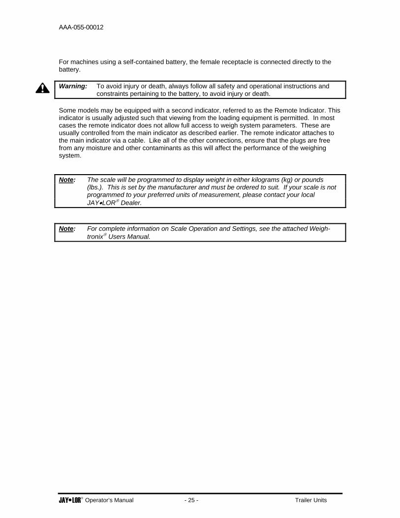
For machines using a self-contained battery, the female receptacle is connected directly to the battery. Warning: To avoid injury or death, always follow all safety and operational instructions and
constraints pertaining to the battery, to avoid injury or death. Some models may be equipped with a second indicator, referred to as the Remote Indicator. This indicator is usually adjusted such that viewing from the loading equipment is permitted. In most cases the remote indicator does not allow full access to weigh system parameters. These are usually controlled from the main indicator as described earlier. The remote indicator attaches to the main indicator via a cable. Like all of the other connections, ensure that the plugs are free from any moisture and other contaminants as this will affect the performance of the weighing system. Note: The scale will be programmed to display weight in either kilograms (kg) or pounds
(lbs.). This is set by the manufacturer and must be ordered to suit. If your scale is not programmed to your preferred units of measurement, please contact your local JAY•LOR® Dealer.
Note: For complete information on Scale Operation and Settings, see the attached Weigh-
tronix® Users Manual.

AAA-055-00012
JAY•LOR® Operator’s Manual - 26 - Trailer Units
Restrictor Blades The restrictor blades are located at the front-left and rear-right corners of the mixing chamber walls. Each restrictor blade comes complete with an adjustment pin that locks the blade into position. When completely inserted, the restrictor blades will slow a large bale or mixed feed from moving around the outside of the mixing chamber, thus allowing the knives to perform aggressive cutting. The restrictor blades may be retracted to the out position to lessen the cutting action. The best position of the restrictor blade is based on user preference. Important: Position the Restrictor Blades in the ‘IN’ (retracted) position during transportation of
the machine to reduce overall width.
ATTACHING/UNHOOKING The machine should always be parked on a level, dry area that is free of debris and foreign objects. Follow this procedure when attaching: 1. Clear the area of bystanders and remove foreign objects from the machine and working area. 2. Make sure there is enough room to back the tractor up to the hitch point. 3. Start the tractor and slowly back it up to the hitch point. 4. Stop the tractor engine, place all controls in neutral, set park brake, and remove ignition key
before dismounting. 5. Adjust the length of the drawbar to give the appropriate dimension between the PTO shaft
and drawbar pin hole. (Refer to Tractor Operator’s Manual). 6. Use the clevis on the hitch to level the machine. 7. Use the jack to raise or lower the hitch pole to align with the drawbar. 8. Install the drawbar pin with provisions for a mechanical retainer such as a ‘Klik’ pin. Install
the retainer. 9. Attach safety chain between the machine and the tractor drawbar cage. 10. Connect the PTO shaft:
• Check that the PTO driveline telescopes easily and the shield rotates freely.
Figure 7 - Restrictor Blade.

AAA-055-00012
JAY•LOR® Operator’s Manual - 27 - Trailer Units
• Attach the driveline to the tractor by retracting the locking pin, slide the yoke over the shaft and push on the yoke until the lock pin clicks into position. Pull on the yoke to be sure the driveline is locked on the shaft.
11. Connect the hydraulics: • Use a clean cloth or paper towel to clean the couplers on the ends of the hoses. Also
clean the area around the couplers on the tractor. • Insert the male ends of the couplers into the remote hydraulic ports on the tractor. • Be sure that each hydraulic circuit on the machine matches up with the correct set of
ports on the tractor. Be sure to match the system with the desired control lever in the tractor.
12. Connect the wiring harness and scale indicator power cord. 13. Route the hoses and wiring harness along the hitch and secure in position to prevent
entanglement with any moving parts. 14. Raise the implement jack, remove and mount on the upper storage bracket. 15. When unhooking from the tractor, reverse the above procedure.
Figure 8 - Typical Attachment to Tractor showing Hitch hookup, PTO shaft hookup, Wire harness and Hydraulic Connections.

AAA-055-00012
JAY•LOR® Operator’s Manual - 28 - Trailer Units
SHEAR BOLT PROTECTED DRIVELINE Should excessive loads be placed on the driveline, the shear bolt will rupture. This is a safety feature; however, do not depend on this as the maximum load indicator. The shear bolt is located on the machine end of the PTO shaft supplied with the machine.
If the shear bolt breaks, it must be replaced with the correct bolt specified by the manufacturer. Refer to the ‘Maintenance and Service Information’ attached for details. For convenience, spare shear bolts are supplied with the machine and are stored on the left side of the hood as directed in the above diagram.
Figure 9 - Shear Bolt Location.

AAA-055-00012
JAY•LOR® Operator’s Manual - 29 - Trailer Units
Front Door Discharge Configurations
Front Door Discharge The front discharge door is controlled hydraulically from the tractor. The door is opened to allow feed out of the mixing chamber onto the conveyor. The door can be raised to any position up to a maximum of 32 inches (81 cm) in height. Use the door guide markings to determine the door opening height. In most cases the door will be opened fully to unload the mixed ration. However, the most suitable door opening height may be determined in combination with the speed of the conveyor and the ground speed of the machine when unloading.
Unloading Conveyor
Figure 10 - Front Discharge Door and Guides.

AAA-055-00012
JAY•LOR® Operator’s Manual - 30 - Trailer Units
The conveyor must be greased on a regular basis, as per the Maintenance Schedule. When unloading the machine, engage the conveyor before opening the discharge door. The speed of the conveyor can be adjusted to suit unloading requirements, by adjusting the flow control on the tractor. The conveyor has an adjustment to tighten or loosen the chain. There is an adjuster located on both sides of the conveyor, at the end of the conveyor opposite to the hydraulic motor. Use wrenches to tighten or loosen the tension on the conveyor chain. Refer to the ‘Maintenance and Service Information’ for more details.
Figure 10 Chain Tensioning

AAA-055-00012
JAY•LOR® Operator’s Manual - 31 - Trailer Units
Dual Discharge – 8’ (96”) or 9’-2” (110”) Conveyors On machines equipped with dual side unloading, the conveyor will unload on either side of the machine. The conveyor is operated by using the controls on the tractor, for left and right discharge. (The conveyor will reverse from its direction of discharge, when the remote is moved to the opposite position)
Figure 11 - 8" Flat Dual Discharge Conveyor
Right/Left Discharge – 6’ Flat w/ Height Adjustable Wing Conveyor Machines that are equipped with right or left discharge have a section of the conveyor that can be raised and lowered. Depending on the options on your JAY•LOR®, raising and lowering the conveyor can be done hydraulically or manually. For models equipped with a manual lift, the conveyor must be stopped in order to raise and lower it. A turnbuckle assembly is used to adjust the wing conveyor height. Simply turn the body on the turnbuckle clockwise or counterclockwise, depending on whether the wing is to be raised or lowered. For models equipped with hydraulic lift discharge, there are two available options for the conveyor operation. One system employs the Lock Collar System. Machines equipped with this system have cylinder lock collars supplied with the equipment. The collars are each different sizes, and are stacked on the lift cylinder’s stroke. The number of lock collars used determines the lowering height of the wing. Once the desired height is set, the conveyor is lowered (cylinder retracts) until it bottoms on the lock collar(s). The hydraulic plumbing is designed such that at this point the

AAA-055-00012
JAY•LOR® Operator’s Manual - 32 - Trailer Units
hydraulic motor on the conveyor will engage. Once the control lever is reversed, the hydraulic motor will disengage and the conveyor wing will rise (cylinder extends).
In the Diverter Valve System, the conveyor must be stopped before a selector valve is activated. To activate the selector valve, simply pull the attached rope. When the rope is pulled, the hydraulic components are used to raise and lower the conveyor. When the conveyor reaches the desired position, release the rope, and the conveyor will begin to unload. Important: Always ensure that there are no obstacles beneath the conveyor that could cause
damage or be damaged when the conveyor is lowered.
Figure 12 - Right/Left 6’ 41” Discharge Conveyor Assembly.
Figure 13 - Overview of Lock Collar System Operation.
CONVEYOR LIFTCYLINDER
LOCK COLLARSPLACED ON CYLINDER
EXPAND LOCKCOLLAR TO FIT
ONTO CYLINDERSHAFT

AAA-055-00012
JAY•LOR® Operator’s Manual - 33 - Trailer Units
REAR DOOR DISCHARGE CONFIGURATIONS The rear discharge door is controlled hydraulically from the tractor. On most units, the rear door option is equipped in addition to the front discharge door option. The hydraulics for controlling the operation of the rear door is connected to the controls for the front discharge door. Selecting between the operation of the rear door and the front door is done through a diverter valve. To open or close the rear discharge door, simply pull the rope attached to the selector valve. This will divert the hydraulic pressure to the rear discharge door. The rear door is then controlled from the tractor. When the door is opened, feed will be discharged from the machine onto the ground. Important: Always ensure that the rear door is completely closed when mixing and/or adding
commodities to prevent ration loss.
Figure 14 - Rear Discharge Door Assembly.

AAA-055-00012
JAY•LOR® Operator’s Manual - 34 - Trailer Units
GEARBOX LUBRICATION The gearbox on your JAY•LOR® Cutter-Mixer-Feeder uses synthetic oil as its lubricant. The oil reservoir, on the right side of the mixer drum, contains the lubricant for the gearbox. The oil has a colorant added, which makes the fluid level more visible in the reservoir. Refer to the ‘Maintenance and Service Information’ section for information on the lubricant specifications for your JAY•LOR® Cutter-Mixer-Feeder. Every JAY•LOR® Cutter-Mixer-Feeder is equipped with an oil reservoir. The polyethylene body is a very durable material, which is able to withstand severe impact. However, if a reservoir is damaged, it must be replaced with an approved reservoir and/or components, recommended by the manufacturer. If a reservoir sustains any damage, call your JAY•LOR® Dealer or Distributor immediately. The polyethylene reservoir has decals indicating the maximum and minimum oil level range under normal operating conditions. At no time is the fluid level to be lower than the minimum recommended level, as damage to the gearbox may occur. If the fluid level is higher than the maximum level, the oil may overflow either at the reservoir or underneath the machine at the gearbox, and cause fluid loss. Check the fluid level in the reservoir daily. The oil reservoir has a filter/breather located on the top, which must be attached to the reservoir at all times. This breather is removable, to allow the filling of the reservoir. If the filter/breather becomes contaminated, remove the breather, and clean it. Follow the instructions as described in the ‘Maintenance and Service Information’ section.
Figure 15 – Plastic Reservoir Assembly.

AAA-055-00012
JAY•LOR® Operator’s Manual - 35 - Trailer Units
FIELD OPERATION
General The operation of the JAY•LOR® Cutter-Mixer-Feeder will vary greatly with the various feeds and climatic conditions. In most instances, “trial and error” is the best method of setting the machine up for a particular commodity to obtain maximum performance. To prevent over-cutting of feed, we suggest starting with the restrictor blades in the out position, and then adjusting to obtain the desired coarseness of the mix. The bulkiest and lightest commodities should be added first. Once these commodities are partially cut and broken apart, others can be added. Additional cutting will take place during mixing, so be careful not to over cut. The order in which the secondary ingredients are added is up to the operator. The type of mix required varies from one operation to the other, and therefore, mixing times and procedures will vary as well. It is recommended that commodities are added to the mixing chamber while the augers are turning for maximum mix efficiency. Operate the PTO driveline at 540 RPM. The auger will rotate at a speed of 41 RPM. Starting the augers from a standstill with a full load in the mixing chamber places additional stress on the machine. Even though it is designed to handle this stress, repetitive startups under load may affect the service life of the machine. If however, due to circumstances, it is required to restart the machine while loaded, retract the restrictor blades all the way in order to decrease starting torque as much as possible. Warning: While loading the machine, be certain that no bucket or loading device comes into
contact with the rotating auger inside the mixing chamber. This may cause serious damage to the mixer and/or loader, and may cause injury or death to the operator.
Warning: Never load an unhitched machine. The machine is designed to be loaded only when
properly hitched to a suitable tractor. Improper loading can cause loss of control, severe injury, or death.
Warning: A loaded machine (machine and payload) may weigh as much as 21,000 lbs (9,500
kg). An operator must use his own discretion when negotiating rough and uneven terrain. Improper operation of the loaded machine can cause loss of control, severe injury, or death.
Danger: Never enter the mixing chamber or go on the conveyor unless all controls are in
neutral, engine stopped, park brake set, ignition key removed and all moving parts have stopped. Failure to follow these safety precautions can result in serious injury or death.
Important: Always remove twine, string, and wrapping material from bales and/or other
commodities from the ground that will be loaded into the mixing chamber. Failure to follow these requirements can cause damage to the machine.

AAA-055-00012
JAY•LOR® Operator’s Manual - 36 - Trailer Units
Cutting and Mixing Procedures Follow these procedures when using the machine: 1. Attach the machine to the tractor, as described in the ‘Attaching/Unhooking’ section. 2. Review the Pre-Operation checklist, as described in the ‘Pre-Operation Checklist’ section. 3. Review the location and function of all controls, as described in the ‘Controls’ section. 4. Transport the machine to the feed storage area. 5. Starting:
Always follow this procedure when starting the machine to minimize high startup loads and the breaking of shear bolts: a. Start the tractor engine and run at low speed. b. Engage the PTO clutch to start auger.
Important: Rapid engagement under a heavy load can break the shear bolt. Engage slowly for the best results.
c. Increase engine speed until the desired RPM is reached. d. Proceed with loading of the ration.
6. Stopping:
a. Stop forward motion. b. Close unloading door. c. Stop conveyor when commodity is off. d. Slow engine to low idle. e. Disengage PTO clutch. f. Stop engine if required.
7. Emergency Stopping:
If an emergency should arise, disengage PTO, turn hydraulics off, stop forward motion and stop engine immediately.
8. Loading Feed Rations:
a. Position the mixer where the loading machine has clear and easy access. b. Start the machine (Refer to #5). Run at rated PTO speed. c. Begin adding ingredients to the mixing chamber in order to cut and mix a uniform feed
ration.
Important: Always remove twine, string, and wrapping material from bales and/or other commodities from the ground that will be loaded into the mixing chamber. Failure to follow these requirements can cause damage to the machine.
Important: It is recommended to add the light and fluffy ingredients into the mixing chamber
first. Then the heavier and denser material will force the lighter ingredients into the mixture.

AAA-055-00012
JAY•LOR® Operator’s Manual - 37 - Trailer Units
d. When adding ingredients, watch the numbers on the scale indicator to monitor the weight of each ingredient as they are added.
e. Mixing times may vary depending on the ingredients being mixed. Typically, a total mixed ration is achieved in 3 to 5 minutes beginning after the last ingredient is added.
Danger: Never enter the mixing chamber or go on the conveyor unless all controls are in
neutral, engine stopped, park brake set, ignition key removed and all moving parts have stopped. Failure to follow these safety precautions can result in serious injury or death.
Unloading Procedures Follow these guidelines when unloading the machine: 1. Transport the machine to the feeding area. 2. If not already done, engage the PTO to start auger rotation. 3. For models equipped with front discharge:
Use a combination of the opening of the unloading door, speed of the conveyor, and ground speed to distribute the feed mixture to the desired areas. Follow this order:
a. Start the conveyor; b. Raise the unloading door; c. Start the auger; d. Drive along feeding bunk/area to unload the feed mixture.
For models equipped with center side or corner door discharge:
Figure 16 - Total Mix Ration (TMR) Achieved in Mixing Chamber.

AAA-055-00012
JAY•LOR® Operator’s Manual - 38 - Trailer Units
Use a combination of the opening of the unloading door and ground speed to distribute the feed mixture to the desired areas. Follow this order:
a. Raise the unloading door; b. Start the auger; c. Begin driving along feeding area to unload the feed mixture.
4. Monitor scale indicator readings to evaluate ration distribution to unloading areas. 5. Continue unloading until mixing chamber is empty or desired amount of mixed ration has
been unloaded. Important: It may be necessary, in order to completely empty the mixer of all commodities, to
turn the auger at the fastest speed possible. This will propel the feed that is resting on the auger off its flighting, and allow the auger to unload this.
6. Unplugging:
Although plugging or clogging of material can occur in several ways, the list identifying ways for plugging or clogging to occur includes but is not limited to:
a. Unloading door; b. Return end of conveyor on left/right discharge models.
Always place controls in neutral, stop engine, set park brake, remove ignition key, and wait for all moving parts to stop before unplugging.
Figure 17 Conveyor Clean Out
Open discharge door or conveyor cleanout boot (if applicable) and clean out the clogged area. Close and secure the conveyor cleanout boot before starting again.

AAA-055-00012
JAY•LOR® Operator’s Manual - 39 - Trailer Units
7. Entangled Material:
Twine, string, and wrapping material that is not removed from bales can get tangled in the auger or under the auger. If this material is not removed from under the auger, it can damage seals and/or other components on the planetary gearbox, which is located underneath the auger center post. Always remove this material as soon as it is noticed.
Danger: Always place controls in neutral, stop engine, set park brake, remove ignition key
and wait for all moving parts to stop before removing material. Failure to follow these safety precautions can result in serious injury or death.
Operating Hints 1. Place the light, fluffy and least dense ingredients into the machine first. In that way, the
heavier and denser material added later will push the light material into the auger. Always place hay (round, square, or loose) into the machine first.
2. Shake the bucket on the loader to control the amount of material being added to the machine.
Watch the weight indicator to know exactly how much of each ingredient you are adding. 3. Operate the auger for 3 to 5 minutes after the last ingredient has been added and before
unloading to ensure a uniform mixture. Mixing times will vary depending on the type of ingredients being mixed. Visually monitor the mixture to ensure that mixing is complete.
4. Consult with a feed nutritionist to determine the best combination of ingredients for your
requirements. Following their recommendations will ensure the best results with your total mixed ration (TMR). This translates into maximum efficiency of your JAY•LOR® Cutter-Mixer-Feeder investment.

AAA-055-00012
JAY•LOR® Operator’s Manual - 40 - Trailer Units
TRANSPORTING The machine is designed to be easily and conveniently moved from location to location. When transporting, follow this procedure: 1. Be sure all bystanders are clear of the machine. 2. Be sure that the unit is hitched positively to the towing vehicle. Always use a retainer in the
drawbar pin and a safety chain between the machine and tractor. 3. Make sure the SMV (Slow Moving Vehicle) emblem and all the lights and reflectors that are
required by the local highway and transport authorities are in place, are clean, and can be seen by all overtaking and oncoming traffic.
4. Raise the conveyor and install the transport lock bracket. 5. Do not allow riders on the machine or tractor. 6. It is not recommended that the unit be transported for long distances when the mixing
chamber is fully loaded. Transporting will compact the mixture and can make startup difficult. 7. Always use hazard flashers on the tractor when transporting unless prohibited by law. 8. It is not recommended that the machine be transported faster than 15 km/hr (10 mph). 9. Never transport faster than the road or terrain conditions will allow you to do safely. 10. Check with the local authorities on the rules and regulations governing the transporting of
agricultural equipment on highways before starting. Always comply with these ordinances and regulations.

AAA-055-00012
JAY•LOR® Operator’s Manual - 41 - Trailer Units
STORAGE Should the machine be stored for a period of time, the machine should be thoroughly inspected and prepared for storage. Repair or replace any worn or damaged components to prevent any unnecessary down time the next time the machine is to be used. Recommended procedure: 1. Wash the entire machine thoroughly using a water hose or pressure washer to remove all
dirt, mud, debris, or residue. 2. Inspect all drives and moving parts. Remove any string, twine, or other material that has
become entangled in the auger knives, axles, or shafts. Be sure the components are clean and move freely.
Danger: Always place controls in neutral, stop engine, set park brake, remove ignition key
and wait for all moving parts to stop before removing material. Failure to follow these safety precautions can result in serious injury or death.
3. Inspect all hydraulic hoses, fittings, lines, couplers, and valves. Tighten any loose fittings.
Replace any hose that is cut, nicked, or abraded, separating from the crimped fitting. 4. Inspect auger and knives for damaged or broken components. Repair or replace
components as required. 5. Lubricate all grease points. Make sure all grease cavities have been filled with grease to
remove any water residue from washing. 6. Raise the conveyor to its maximum height and install the lock channel. 7. Apply grease to the exposed cylinder rams. This includes the discharge door cylinder and
the conveyor lift cylinder, if equipped. 8. Touch up all paint nicks and scratches to prevent rusting. 9. Move the machine to its storage position. 10. Select an area that is dry, level, and free of debris. 11. Place planks under the jack for added support if required. 12. Unhook the machine from the tractor. 13. Block the wheels on the machine. 14. If the machine is not to be used for an extended period, consider removing the scale indicator
from the machine and place in a clean and dry environment. Use the original packaging if available. Place all weigh bars and power cords so that they will not be exposed to weathering and/or damage.

AAA-055-00012
JAY•LOR® Operator’s Manual - 42 - Trailer Units
TROUBLESHOOTING
General Troubleshooting Your JAY•LOR® Cutter-Mixer-Feeder is designed to receive a variety of feed material in its mixing chamber to cut and mix prior to unloading. It is a simple and reliable system that requires minimal maintenance. The following section lists common problems, causes, and solutions to the problems you may encounter with your JAY•LOR® Cutter-Mixer-Feeder. Should any maintenance and service be required as a result of troubleshooting, refer to the ‘Maintenance and Service Information’ for assistance. If you encounter a problem that is difficult to solve, even after having read through this troubleshooting section, please call your dealer or distributor. Before you call, please have this Operator’s Manual and the serial number from your machine ready. PROBLEM CAUSE SOLUTION Material wraps around knives.
- Knives dull or worn out. - Check auger, remove entangled material.
- Check knife condition. Replace any worn, bent, and/or damaged knives.
Conveyor doesn’t move. - Insufficient oil flow.
- Cold temperatures - Conveyor slats frozen
down. - Conveyor jammed.
- Increase oil flow at tractor or flow divider.
- Warm machine before operating.
- Check oil level in tractor reservoir. Add as required.
- Clear material out of slat pathway underneath the conveyor assembly.
Shear bolt failure. - Auger doesn’t turn freely.
- PTO engaged too quickly.
- Determine the cause of hard turning. Auger must turn freely.
- Remove entangled material from auger and knives.
- Replace shear bolt. - Engage PTO slowly.
See tractor Operator’s Manual.
‘Dead Spot’ during mixing. - Material will not mix in certain locations inside the mixing chamber, commonly the front and back areas of the mixing chamber.
- Make sure the machine is level when mixing.
- Check knife condition. Replace accordingly.
- Check angling blade condition. Replace accordingly

AAA-055-00012
JAY•LOR® Operator’s Manual - 43 - Trailer Units
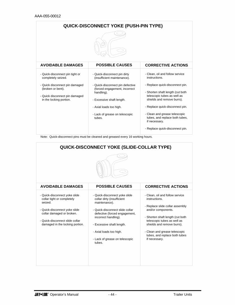
Driveline Troubleshooting The following section lists common problems, causes, and solutions to the problems you may encounter with the driveline components found on your JAY•LOR® Cutter-Mixer-Feeder. Refer to the ‘Maintenance and Service Information’ Section for the regular service requirements for these and other related components.
AAA-055-00012
JAY•LOR® Operator’s Manual - 44 - Trailer Units
- Quick-disconnect pin tight or completely seized.
- Quick disconnect pin damaged (broken or bent).
- Quick disconnect pin damaged in the locking portion.
- Quick-disconnect pin dirty (insufficient maintenance).
- Quick-disconnect pin defective (forced engagement, incorrect handling).
- Excessive shaft length.
- Axial loads too high.
- Lack of grease on telescopic tubes.
- Clean, oil and follow service instructions.
- Replace quick-disconnect pin.
- Shorten shaft length (cut both telescopic tubes as well as shields and remove burrs).
- Replace quick-disconnect pin.
- Clean and grease telescopic tubes, and replace both tubes, if necessary.
- Replace quick-disconnect pin.
AVOIDABLE DAMAGES POSSIBLE CAUSES CORRECTIVE ACTIONS
QUICK-DISCONNECT YOKE (PUSH-PIN TYPE)
Note: Quick-disconnect pins must be cleaned and greased every 16 working hours.
CORRECTIVE ACTIONSPOSSIBLE CAUSESAVOIDABLE DAMAGES
QUICK-DISCONNECT YOKE (SLIDE-COLLAR TYPE)
- Quick-disconnect yoke slide collar tight or completely seized.
- Quick-disconnect yoke slide collar damaged or broken.
- Quick-disconnect slide collar damaged in the locking portion.
- Quick-disconnect yoke slide collar dirty (insufficient maintenance).
- Quick-disconnect slide collar defective (forced engagement, incorrect handling).
- Excessive shaft length.
- Axial loads too high.
- Lack of grease on telescopic tubes.
- Clean, oil and follow service instructions.
- Replace slide collar assembly and/or components.
- Shorten shaft length (cut both telescopic tubes as well as shields and remove burrs).
- Clean and grease telescopic tubes, and replace both tubes if necessary.

AAA-055-00012
JAY•LOR® Operator’s Manual - 45 - Trailer Units
- Yoke ears deformation. - Excessive shaft length.
- Axial loads too high.
- Excessive working angle and torque.
- Shorten shaft length (cut both telescopic tubes as well as shields and remove burrs).
- Replace defective yokes.
- Clean and grease telescopic tubes, and replace both tubes if necessary.
- Replace defective yokes.
- Verify compatibility between shaft and working conditions (torque vs. angle).
- Disengage tractor P.T.O. during cornering or when lifting or lowering the implement.
- Replace defective yokes.
AVOIDABLE DAMAGES POSSIBLE CAUSES CORRECTIVE ACTIONS
YOKE
- Yoke ears distorted. - Overload caused by high starting and peak torques.
- Engage P.T.O. more carefully.
- Use appropriate shear bolt.
- Replace defective yokes.
- Avoid excessive working angle.
- Disengage tractor P.T.O. during cornering.
- Replace defective yokes.
- Excessive working angle.- Yoke ears worn or pounded.

AAA-055-00012
JAY•LOR® Operator’s Manual - 46 - Trailer Units
- Cross arms broken. - Extreme torque peak or shock load.
- Axial loads too high.
- Use appropriate safety device.
- Shorten P.T.O. shaft.
- Replace defective cross bearings.
AVOIDABLE DAMAGES POSSIBLE CAUSES CORRECTIVE ACTIONS
UNIVERSAL JOINT (CROSS) KIT
- Accelerated wear of cross kit. - Excessive continuous torque and/or excessive working angle.
- Inadequate lubrication.
- Verify compatibility between shaft and working conditions.
- Carefully follow lubricating instructions.
- Replace defective cross bearings.
- Verify compatibility between shaft and working conditions.
- Carefully follow lubricating instructions.
- Replace defective cross bearings.
- Excessive continuous torque and/or excessive working angle.
- Inadequate lubrication.
- Bearing caps turning in their cross journal.
- Overheated bearing caps.
Note: Cross bearings must be greased every 8 working hours.

AAA-055-00012
JAY•LOR® Operator’s Manual - 47 - Trailer Units
- Excessive wear of shield bearings.
- Insufficient lubrication.
- Incorrect chain mounting.
- Shield interfering with implement.
- Follow lubrication instructions.
- Mount chain to allow maximum angularity.
- Avoid contact of the shields with fixed parts of the machine or tractor.
- Replace shield bearings.
AVOIDABLE DAMAGES POSSIBLE CAUSES CORRECTIVE ACTIONS
SHIELD
- Avoid contact of the shields with fixed parts of the machine or tractor.
- Mount chain to allow maximum angularity.
- Replace defective parts.
- Shield interfering with implement.
- Incorrect chain mounting.
- Chain moving or failure.
Note: Shield bearings must be greased every 8 working hours.
- Eliminate interference between guard cones and any part on the tractor and/or implement.
- Avoid excessive angle during cornering or when lifting or lowering the implement.
- Replace damaged guard cones.
- Guard cone in contact with components on the tractor and/or implement.
- Excessive angularity.
- Guard cone damaged.
- Eliminate interference between guard cones and any part on the tractor and/or implement.
- Replace damaged tubes.
- Adjust guard tubes length with longer tubes.
- Guards in contact with components on the tractor and/or implement.
- Guard tubes overlap too short or no overlap at all with extended P.T.O. driveshaft.
- Guard tubes damaged (deformed and split at one side).

AAA-055-00012
JAY•LOR® Operator’s Manual - 48 - Trailer Units
STANDARD MODEL SPECIFICATIONS
4350 Trailer Cutter-Mixer-Feeder
MODEL 4350 TRAILER CUTTER-MIXER-FEEDER Main Component Detail Specification Mixing Chamber Capacity 350 cu.ft. (9.9 m3)
Auger Assembly Features Complete w/ 7 Tungsten Carbide Cutter Blades.
Speed 41 revolutions per minute (RPM).
Frame Features Heavy duty, with provision for 3-point weigh scale system.
Wheel Assembly (2) Tire and Wheel Assemblies
12.5 x 16 - 12 Ply Firestone Tire on 15 x 10, 8 Bolt 6000 lb. Rim with Valve Guard.
Hub Assembly (2) Hub Assemblies 8,000 lb. Farm Implement Hub w/ Grease Lubrication.
Width and Type 36” (91 cm) wide, chain/slat discharge, various option packages available. Conveyor
Assembly Conveyor Drive Assembly Hydraulic Orbit Motor, 7.5 cu.in/rev.
PTO Shaft #6, 540 RPM operating speed, w/ shear bolt protection. 1-3/8” dia., 6-spline hookup to tractor.
Maximum Operating Speed 540 revolutions per minute (RPM)
Drivetrain
Horsepower Requirement
60 HP Minimum; depends on commodities mixed.
Hydraulics Tractor Hydraulic System Requirements
Minimum of 2 sets of Remote Hydraulic Outlets. 5 GPM (19 L/min) at 2000 psi (13,750 kPa)
Weight 6405 lbs. (2911 kg) Dependent on equipped options. * - Due to continual product development, specifications are subject to change without notice.
AAA-055-00012
JAY•LOR® Operator’s Manual - 49 - Trailer Units
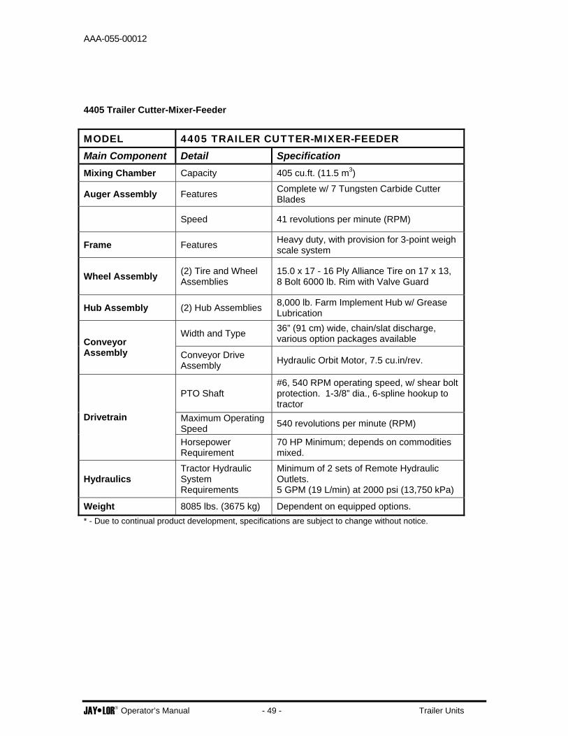
4405 Trailer Cutter-Mixer-Feeder
MODEL 4405 TRAILER CUTTER-MIXER-FEEDER Main Component Detail Specification Mixing Chamber Capacity 405 cu.ft. (11.5 m3)
Auger Assembly Features Complete w/ 7 Tungsten Carbide Cutter Blades
Speed 41 revolutions per minute (RPM)
Frame Features Heavy duty, with provision for 3-point weigh scale system
Wheel Assembly (2) Tire and Wheel Assemblies
15.0 x 17 - 16 Ply Alliance Tire on 17 x 13, 8 Bolt 6000 lb. Rim with Valve Guard
Hub Assembly (2) Hub Assemblies 8,000 lb. Farm Implement Hub w/ Grease Lubrication
Width and Type 36” (91 cm) wide, chain/slat discharge, various option packages available Conveyor
Assembly Conveyor Drive Assembly Hydraulic Orbit Motor, 7.5 cu.in/rev.
PTO Shaft #6, 540 RPM operating speed, w/ shear bolt protection. 1-3/8” dia., 6-spline hookup to tractor
Maximum Operating Speed 540 revolutions per minute (RPM)
Drivetrain
Horsepower Requirement
70 HP Minimum; depends on commodities mixed.
Hydraulics Tractor Hydraulic System Requirements
Minimum of 2 sets of Remote Hydraulic Outlets. 5 GPM (19 L/min) at 2000 psi (13,750 kPa)
Weight 8085 lbs. (3675 kg) Dependent on equipped options. * - Due to continual product development, specifications are subject to change without notice.

AAA-055-00012
JAY•LOR® Operator’s Manual - 50 - Trailer Units
4425 Trailer Cutter-Mixer-Feeder
MODEL 4425 TRAILER CUTTER-MIXER-FEEDER Main Component Detail Specification Mixing Chamber Capacity 425 cu.ft. (12.0 m3)
Auger Assembly Features Complete w/ 7 Tungsten Carbide Cutter Blades
Speed 41 revolutions per minute (RPM)
Frame Features Heavy duty, with provision for 3-point weigh scale system
Wheel Assembly (2) Tire and Wheel Assemblies
15.0 x 17 - 16 Ply Alliance Tire on 17 x 13, 8 Bolt 6000 lb. Rim with Valve Guard
Hub Assembly (2) Hub Assemblies 8,000 lb. Farm Implement Hub w/ Grease Lubrication
Width and Type 36” (91 cm) wide, chain/slat discharge, various option packages available Conveyor
Assembly Conveyor Drive Assembly Hydraulic Orbit Motor, 8.0 cu.in/rev.
PTO Shaft #6, 540 RPM operating speed, w/ shear bolt protection. 1-3/8” dia., 6-spline hookup to tractor
Maximum Operating Speed 540 revolutions per minute (RPM)
Drivetrain
Horsepower Requirement
70 HP Minimum; depends on commodities mixed.
Hydraulics Tractor Hydraulic System Requirements
Minimum of 2 sets of Remote Hydraulic Outlets. 5 GPM (19 L/min) at 2000 psi (13,750 kPa)
Weight 7495 lbs. (3406 kg) Dependent on equipped options. * - Due to continual product development, specifications are subject to change without notice.

AAA-055-00012
JAY•LOR® Operator’s Manual - 51 - Trailer Units
4575 Trailer Cutter-Mixer-Feeder
MODEL 4575 TRAILER CUTTER-MIXER-FEEDER Main Component Detail Specification Mixing Chamber Capacity 575 cu.ft. (16.3 m3)
Auger Assembly Features Complete w/ 10 Tungsten Carbide Cutter Blades
Speed 41 revolutions per minute (RPM)
Frame Features Heavy duty, with provision for 3-point weigh scale system
Wheel Assembly (2) Tire and Wheel Assemblies
15.0 x 17 - 16 Ply Alliance Tire on 17 x 13, 8 Bolt 6000 lb. Rim with Valve Guard
Hub Assembly (2) Hub Assemblies 8,000 lb. Farm Implement Hub w/ Grease Lubrication
Width and Type 36” (91 cm) wide, chain/slat discharge, various option packages available Conveyor
Assembly Conveyor Drive Assembly Hydraulic Orbit Motor, 7.5 cu.in/rev.
PTO Shaft #8, 540 RPM operating speed, w/ shear bolt protection. 1-3/8” dia., 6-spline hookup to tractor
Maximum Operating Speed 540 revolutions per minute (RPM)
Drivetrain
Horsepower Requirement
80 HP Minimum; depends on commodities mixed.
Hydraulics Tractor Hydraulic System Requirements
Minimum of 2 sets of Remote Hydraulic Outlets. 5 GPM (19 L/min) at 2000 psi (13,750 kPa)
Weight 9,375 lbs. (4252 kg) Dependent on equipped options. * - Due to continual product development, specifications are subject to change without notice.

AAA-055-00012
JAY•LOR® Operator’s Manual - 52 - Trailer Units
DRUM EXTENSION INSTALLATION (IF APPLICABLE) Depending on the JAY•LOR® Cutter-Mixer-Feeder model and options you have chosen, your machine may be equipped with a plastic (HDPE) drum extension. If so, please follow these steps to install the extension on your single auger machine: 1. Begin by unrolling the entire length of the HDPE extension. Measure the full length of the section and mark the half way point. The section should be 38’ in length. 2. Line up the half way point of this section with the center of one of the v-panels (side panels), so that the extension sits flush on the angle iron at the top of the drum. Make sure to choose the v-panel opposite to the side you will be loading on. There will be overlap of the extension and this overlap will add strength to the loading side (see Figure 18 below). 3. Using the holes in the angle iron as a guide, drill a hole (1/2” diameter) in the extension and fasten to the angle iron at or near this point at the center of the v-panel. Make sure that bolt heads sit on the outside of the extension. 4. Wrap the two ends around the angle iron as shown in Figure 18 below. First clamp the inside end to the angle iron, making sure that the extension is pulled as tight as possible. Wrap the other end so it overlaps the inner extension section and clamp together. Make sure this end is also as tight as possible.
Figure 18 Securing Extension
6. Beginning just after the extension overlap (see Figure 18), start drilling and fastening the plastic extension to the angle iron, using the predrilled angle iron holes as a guide. Move in one direction around the drum. 7. Using the remaining hardware, drill and fasten a second row at the top of the overlapping extension sections.