Operator’s Manual - Navicom Dynamics€¦ · GyroPilot Operator’s Manual GyroPilot Operator’s...
15
GyroPilot V3 Operator’s Manual
Transcript of Operator’s Manual - Navicom Dynamics€¦ · GyroPilot Operator’s Manual GyroPilot Operator’s...

GyroPilot V3
Operator’s Manual

GyroPilot Operator’s Manual
GyroPilot Operator’s Manual Page 1
TABLE OF CONENTS
1 UNPACKING ................................................................................................................................... 3
2 PRODUCT OVERVIEW .................................................................................................................. 3
3 BEFORE USE ................................................................................................................................. 3
3.1 CHARGING INSTRUCTIONS 3
4 USAGE ............................................................................................................................................ 4
4.1 SWITCHING ON 4 4.2 CONNECTIVITY 4 4.3 NORMAL OPERATION 5 4.4 EMERGENCY GNSS MODE 6
5 FEATURES ..................................................................................................................................... 7
5.1 LED INDICATORS 7 5.2 POWER BUTTON PRESSES 8 5.3 USE WITH GYROPILOT PLUS 8 5.4 LEAVE-BEHIND ALARM 9
6 HANDLING AND STORAGE ........................................................................................................ 10
6.1 AFTER USE 10 6.2 DRY-POUCH CARRY BAG 10 6.3 LONG-TERM STORAGE 10 6.4 OPERATE UNDER EXTREME TEMPERATURES 10
7 SPECIFICATIONS ........................................................................................................................ 12
7.1 TECHNICAL AND PERFORMANCE 12 7.2 PHYSICAL AND ENVIRONMENTAL 12
8 SUPPORT ..................................................................................................................................... 13
8.1 SERVICE AND HELP 13 8.2 WARRANTY INFORMATION 13

GyroPilot Operator’s Manual
GyroPilot Operator’s Manual Page 2
DISCLAIMER
The GyroPilot unit and any supporting software are Aids to
Navigation.
They are very effective tools developed to support the
person executes the pilotage. The equipment is intended
to be used as part of an integrated strategy incorporating
all the accepted principals of Bridge Resource
Management. Reliance on the GyroPilot as the sole
means of monitoring the ship's navigation position must be
avoided.
Your use of this product and information it provides is at
your own risk. You assume full responsibility and risk of loss
resulting from the use of this product or information it
provides. None of Navicom Dynamics Ltd. or its affiliates,
or any directors, partners, principals, shareholders or
employees thereof will be liable for any special, indirect,
incidental, consequential or punitive damages or any
other damages whatsoever, whether in an action of
contract, statute, tort (including, without limitation,
negligence) or otherwise, relating to the use of this
product or information it provides.

GyroPilot Operator’s Manual
GyroPilot Operator’s Manual Page 3
1 UNPACKING
Unpack the GyroPilot and ancillary items from the box and check no
items are missing or damaged.
Items shipped are as follows:
GyroPilot main unit
GyroPilot to AIS Pilot Plug data and charging cable
Mains to USB power supply unit (with various country adapter plugs)
GyroPilot dry-pouch carry bag
Quick-Start guide with link to operator’s manual
2 PRODUCT OVERVIEW
The GyroPilot is a smart AIS Pilot Plug interface with added solid-state
gyros and backup GNSS receiver.
The gyro serves two purposes:
a. Output Rate of Turn (ROT) of the vessel
b. Smooth the raw AIS heading data, which is only available in integer
degrees from the Pilot Plug, and output this to 1 decimal place for
use by navigation software
All ship AIS data received (both own ship and other ships) is passed over
the wireless link for use in navigation software.
The GyroPilot also outputs its battery status for display by the navigation
software.
On loss of AIS input, the GyroPilot will switch to its internal GNSS sensor
and output its position over the same wireless link.
GyroPilot Plus is available as an optional add on module. It is a highly
accurate, wireless and independent GNSS sensor for the GyroPilot.
3 BEFORE USE
It is recommended the GyroPilot is fully charged before use.
3.1 Charging Instructions
Plug the USB end of the cable into the power supply unit then plug the
power supply unit into the mains.

GyroPilot Operator’s Manual
GyroPilot Operator’s Manual Page 4
Plug the other end of cable connector on the GyroPilot.
Observe the battery LED on the front of the GyroPilot – see LED section
for full details.
The GyroPilot can be charged whether it is switched off
(recommended) or on. If charging when on, note that the charge time
will be longer, and that care must be taken not to move the unit if it is in
use (as described in the following section).
4 USAGE
4.1 Switching On
Do not switch on the GyroPilot until it has been placed on a flat surface
in the required operating location. The base of the unit has a rubberised
coating to help give it good adhesion to any flat surface.
For best performance, ensure the unit is placed on a flat surface.
Plug the GyroPilot cable into the AIS Pilot Plug.
Switch on the GyroPilot by pushing and holding the power button for
approximately 2 seconds. The LEDs on the front of the unit will briefly
flash in sequence along with beeps to indicate switch-on. After the
initial start sequence the LEDs will follow the sequence given in Section
5.1.
Once the device is turned on, ensure that the unit is not disturbed. Any
disturbance which causes the device to move will reduce the quality of
the ROT information produced by the device.
To switch the unit off, simply repeat the process of pressing and holding
the power button for 2 seconds. The LEDs will then turn off entirely.
4.2 Connectivity
The GyroPilot connects to a laptop or tablet by either a Wi-Fi or
Bluetooth connection depending on the model.
The unit label, located on the bottom of the GyroPilot, indicates
whether the unit is a Wi-Fi or a Bluetooth model.

GyroPilot Operator’s Manual
GyroPilot Operator’s Manual Page 5
For Bluetooth connections please refer to your laptop and operating
system manual on how to setup a Bluetooth connection. The baud rate
is 38400.
For Wi-Fi connections, the SSID of the GyroPilot is named after its serial
number, and the IP address and port over which the data is sent are as
follows:
192.168.10.10 : 5003
Please note that if a hardwired connection is preferred (rather than a
wireless connection), this can be established using the supplied USB
cable. Once connected, the GyroPilot will be treated as a “USB Serial
Port” by your laptop; this COM port can be selected in your chosen ECS.
4.3 Normal Operation
As soon as it is switched on, the GyroPilot will search for the AIS data
coming from the Pilot Plug, regardless of any errors in the wiring of the
Pilot Plug. This can take up to 30 seconds.
As soon as ship’s data is received, the GyroPilot will automatically
initialise its gyroscope calibration process. This calibration can take up
to one minute.
ONE MINUTE GYRO CALIBRATION FOLLOWING STARTUP
Once the calibration is complete, GyroPilot will autonomously output
ROT data, smoothed heading and all AIS data from the Pilot Plug and
pass it over the wireless connection.
Please note that the GyroPilot will not automatically correct any
heading error from the ship, but most good pilot navigation software will
offer the pilot the opportunity to enter a heading correction if a ship’s
gyro error is observed.
All AIS messages received will be passed over the wireless connection
to the laptop. The ECS should therefore be set up to take position
information via AIS messages when in normal operating mode.
IMPORTANT: DO NOT TOUCH THE GYROPILOT ONCE SWITCHED ON
If the unit is moved for any reason, this will disturb the gyro and it will
output invalid data. The fastest way to regain accurate data is to switch
the unit off and on again, after which it will repeat the one-minute
calibration process.

GyroPilot Operator’s Manual
GyroPilot Operator’s Manual Page 6
The unit is supplied with a rubberised mat which can be used to reduce
the chances of slipping under accidental cable movement.
4.4 Emergency GNSS Mode
In the event that data is lost from the AIS Pilot Plug, the GyroPilot will
automatically set itself to GNSS emergency mode and output standard
global position and COG data.
The receiver is a combined GPS/GLONASS receiver. The purpose of the
receiver is to provide emergency functionality that is better than a
smart-phone or a similar device and whose data is able to be
transferred to any ECS. During this time, the GyroPilot will not output ROT
or smoothed Heading.
During normal AIS operation, the GPS receiver is switched off to save
battery power. The GNSS receiver automatically switches on if the AIS
feed is lost for approximately 2 minutes.
Once the GNSS receiver is switched on, there will be a short delay while
the receiver acquires and computes a solution; this delay will vary in
length of time depending on the view of the sky that it is able to see.
Position information from the GNSS receiver will be sent over the wireless
connection using NMEA sentences. The ECS should therefore be set up
to take position information via NMEA when in emergency GNSS mode.
Once AIS data is found again, the unit will automatically switch out of
emergency GNSS mode and back to normal operation, including
output of ROT and smoothed Heading
WARNING: EMERGENCY USE ONLY
The purpose of this GNSS functionality is for emergency use when no
other options are available. We recommend that the internal GyroPilot
GNSS receiver should not be relied upon for normal navigation.

GyroPilot Operator’s Manual
GyroPilot Operator’s Manual Page 7
5 FEATURES
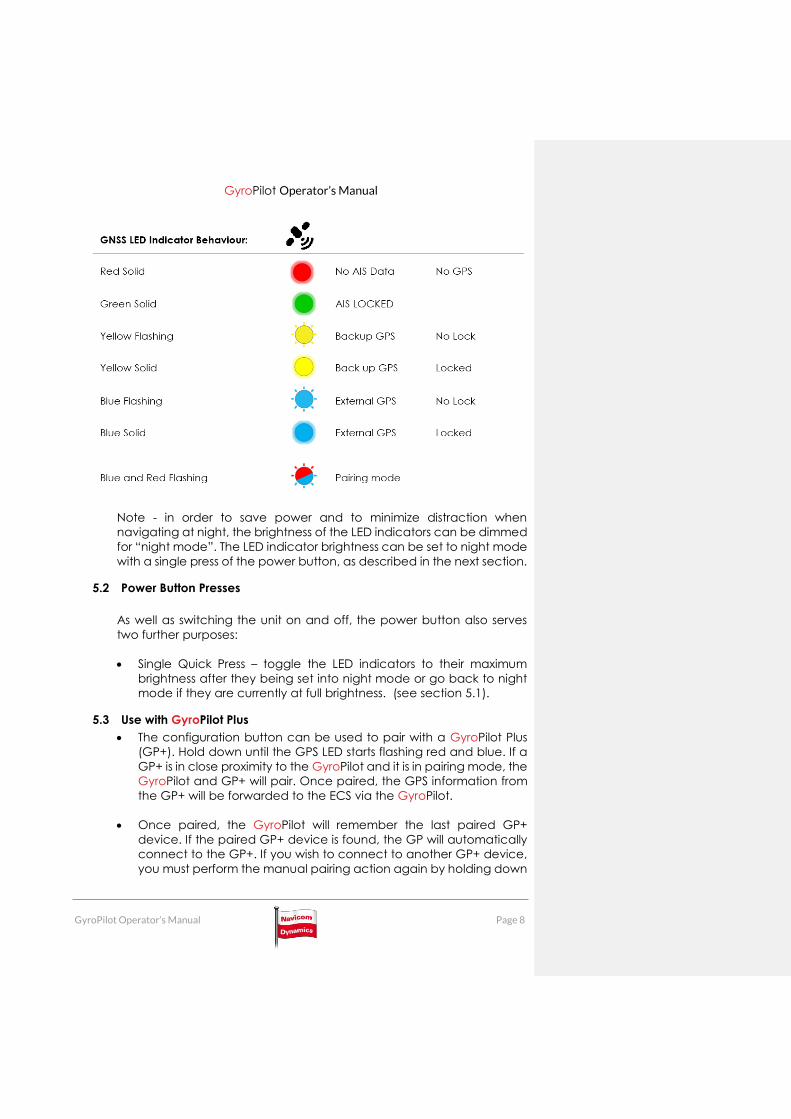
5.1 LED Indicators
There are three LED indicators on the front of the GyroPilot unit – these
show the status of the battery, the status of the data link and the GNSS
status.
The Three LEDs are labelled as follows:
The GNSS LED which is represented by a satellite symbol is present
on the left of the front panel
The CONNECTION LED which is represented by 2 arrows pointing
in opposite directions is present in the middle of the front panel
The Battery LED which is represented by a battery icon is present
on the right of the front panel
GyroPilot Operator’s Manual
GyroPilot Operator’s Manual Page 8
Note - in order to save power and to minimize distraction when
navigating at night, the brightness of the LED indicators can be dimmed
for “night mode”. The LED indicator brightness can be set to night mode
with a single press of the power button, as described in the next section.
5.2 Power Button Presses
As well as switching the unit on and off, the power button also serves
two further purposes:
Single Quick Press – toggle the LED indicators to their maximum
brightness after they being set into night mode or go back to night
mode if they are currently at full brightness. (see section 5.1).
5.3 Use with GyroPilot Plus
The configuration button can be used to pair with a GyroPilot Plus
(GP+). Hold down until the GPS LED starts flashing red and blue. If a
GP+ is in close proximity to the GyroPilot and it is in pairing mode, the
GyroPilot and GP+ will pair. Once paired, the GPS information from
the GP+ will be forwarded to the ECS via the GyroPilot.
Once paired, the GyroPilot will remember the last paired GP+
device. If the paired GP+ device is found, the GP will automatically
connect to the GP+. If you wish to connect to another GP+ device,
you must perform the manual pairing action again by holding down

GyroPilot Operator’s Manual
GyroPilot Operator’s Manual Page 9
the configuration button on both units and waiting until the units
have paired.
IMPORTANT
When using the GyroPilot along with the GP+ unit, it is critical that the
pilot pay close attention to the source from which you are acquiring
the position data. The GNSS LED (refer to GNSS LED Indicator) should
be periodically monitored to ensure that the GP+ unit is able to relay
the GNSS information to the GyroPilot unit. If the GyroPilot is not able
to connect to a GP+ unit, the electronic charting software may
switch to using the position form the AIS stream of the pilot plug.
Monitoring the GNSS indicator will enable the pilot to quickly change
the antenna offsets in software in case the source of the GPS
information changes - thus ensuring that an accurate representation
of the vessel position on the ECS software
5.4 Leave-Behind Alarm
Once a laptop connection is established (either wireless or hard-wired),
the GyroPilot will monitor the status of this connection. If the connection
is lost, a 30-second timer will start, after which time an alarm will sound.
The purpose of this alarm is to act as a warning in case the pilot leaves
the unit behind when leaving the ship. Note that this alarm can be
silenced by re-establishing the connection to the laptop, by double-
pressing the power button as described above, or by switching the unit
off.
5.5 COG and SOG generation at low velocities
When the gyro pilot + Is operating at low velocities, pilots may need to ensure that the generation of the COG and SOG are set to be derived from the GPS position. It is important to note that at low velocities the positional error as a fraction of the distance moved is greater, hence the derived COG and SOG information may not be of acceptable accuracy. In order to have COG and SOG information available at low velocities, pilots may need to enable this feature in their ECS. The process of enabling this feature is different for each type of ECS. Because each ECS behaves differently, the user is advised to consult the owner’s manual for their ECS.
Commented [DS1]: ay

GyroPilot Operator’s Manual
GyroPilot Operator’s Manual Page 10
Outlined below is a list of how to how to access this information for a few different types of ECS. Qastor: Qastor will automatically derive a COG and SOG solution. SEAiq: In SEAiq, the settings can be found by tapping the gear icon. Under
the NMEA/AIS heading tap “Navicom Dynamics PPUs”. Turn on the “Derive COG/SOG from GPS” TRANSAS PILOT PRO: In settings (Tap the multiple Gear icon) under the
heading NMEA, tap the “calculated COG & SOG” and choose the velocity at which you would like to use derived COG and SOG.
6 HANDLING AND STORAGE
6.1 After Use
When finished with the GyroPilot, switch it off, wipe the device if
there is moisture, and store in a suitable dry place. Recharge as
soon as possible.
6.2 Dry-Pouch Carry Bag
We recommend that the carry bag provided be used to carry
the GyroPilot both to, from, and when onboard a vessel, since it
protects against the elements. In order to close the bag, fold the
top band away from away from the logo side of the pouch (i.e.
to the rear side) at least once, and then secure the plastic
fasteners on the rear side.
6.3 Long-Term Storage
If the unit is not going to be used for a long time, ensure the
battery is around 50% charged before storage. It is
recommended that the battery be recharged once every 3
months.
6.4 Operate Under Extreme Temperatures
If the unit is to be used on an open bridge without an AIS
installation, particularly in temperatures below -20°C, it is
important that the unit is warmed when switched on. Keep the

GyroPilot Operator’s Manual
GyroPilot Operator’s Manual Page 11
unit in a place where the temperature is above 0°C before taking
the unit outside and setting up. In extreme temperatures (hot or
cold) the battery life will be shorter than specified.
GyroPilot Operator’s Manual
GyroPilot Operator’s Manual Page 12
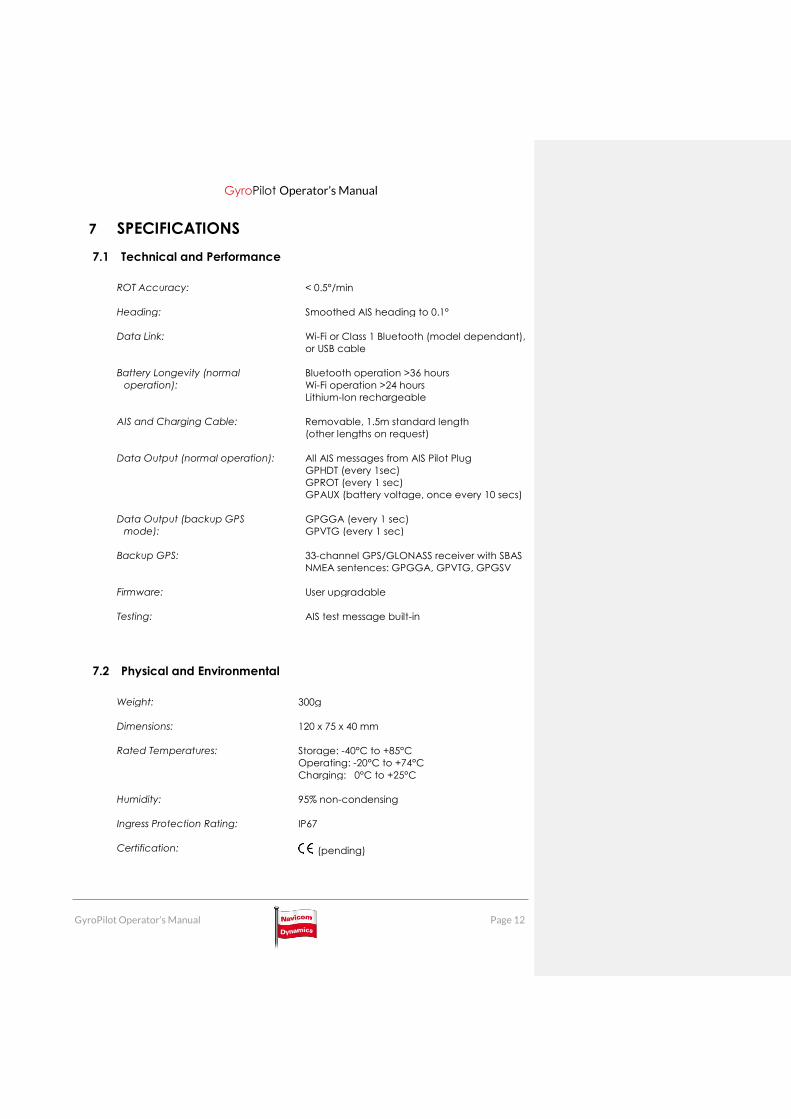
7 SPECIFICATIONS
7.1 Technical and Performance
ROT Accuracy: < 0.5°/min
Heading: Smoothed AIS heading to 0.1°
Data Link: Wi-Fi or Class 1 Bluetooth (model dependant),
or USB cable
Battery Longevity (normal
operation):
Bluetooth operation >36 hours
Wi-Fi operation >24 hours
Lithium-Ion rechargeable
AIS and Charging Cable: Removable, 1.5m standard length
(other lengths on request)
Data Output (normal operation): All AIS messages from AIS Pilot Plug
GPHDT (every 1sec)
GPROT (every 1 sec)
GPAUX (battery voltage, once every 10 secs)
Data Output (backup GPS
mode):
GPGGA (every 1 sec)
GPVTG (every 1 sec)
Backup GPS: 33-channel GPS/GLONASS receiver with SBAS
NMEA sentences: GPGGA, GPVTG, GPGSV
Firmware: User upgradable
Testing: AIS test message built-in
7.2 Physical and Environmental
Weight: 300g
Dimensions: 120 x 75 x 40 mm
Rated Temperatures: Storage: -40°C to +85°C
Operating: -20°C to +74°C
Charging: 0°C to +25°C
Humidity: 95% non-condensing
Ingress Protection Rating: IP67
Certification: (pending)

GyroPilot Operator’s Manual
GyroPilot Operator’s Manual Page 13
8 SUPPORT
8.1 Service and Help
Should you experience any technical issues, please contact your approved service
agent as your first line of support.
If unavailable, please contact Navicom Dynamics directly using the information
below:
Phone: + (64) 9 915-5330
Fax: + (64) 9 915-5331
Website: www.navicomdynamics.com
Support email: [email protected]
Physical Address: Navicom Dynamics
(for couriers) 2 Parkhead Place
Albany
Auckland 0632
NEW ZEALAND
Returning goods: Before shipping goods to Navicom Dynamics, please request an
RMA number. No goods will be accepted without an RMA. An RMA form can be found
and filled in on our web site www.navicomdynamics.com/repairs-and-returns
Office hours: Our office hours are from 9am to 5.30pm Mon–Fri NZ time. We are happy
to take urgent calls outside work hours.
Note: NZ Standard Time is 12 hours ahead of UTC. In summer months this is adjusted
forwards by one hour. To confirm the actual time in New Zealand, please visit
www.timeanddate.com
8.2 Warranty Information
Your GyroPilot system was sold to you with the following warranty periods:
GyroPilot 24 months
Battery 12 months
The warranty must be validated by registering online at
www.navicomdynamics.com/support within three months of your product being
shipped to you.
Please read this operator’s manual carefully, as failure to operate or handle the
equipment properly may invalidate the warranty.

GyroPilot Operator’s Manual
GyroPilot Operator’s Manual Page 14
Document Revisions
Date Revision
8/12/2017 Initial Issue
5/02/2018 Changed error with led status. Added section on COG and SOG
at low velocities.


![RT 411 - Navicomdownload.navicom.fr/navicom/manuels/VHF PORTABLES/RT 411/RT … · Navicom RT-411 - 7 - Touche [MEM] Un appui court sur la touche [MEM] permet de mettre l'appareil](https://static.fdocuments.net/doc/165x107/5f5cbfabae26ee1b74450d88/rt-411-portablesrt-411rt-navicom-rt-411-7-touche-mem-un-appui-court.jpg)