OPERATOR AND PARTS MANUAL Grain Cart
118
OPERATOR AND PARTS MANUAL Grain Cart Model 1060 and 1360 062013 | Rev 1 | 88664296 072013 88664296
Transcript of OPERATOR AND PARTS MANUAL Grain Cart
OPERATOR AND PARTS MANUAL
Grain CartModel 1060 and 1360
072013 88664296
6990633 (1-13) Printed in U.S.A. © Bobcat Company 2013 062013 | Rev 1 | 88664296


Table of Contents - 1060 and 1360 Grain Cart
TABLE OF CONTENTS
INTRODUCTION . . . . . . . . . . . . . . . . . . . . . . . . . . . . . . . . . . . . . . . . . . . . . . . . . . . . . . . . . . . . . . . .5
SAFETY . . . . . . . . . . . . . . . . . . . . . . . . . . . . . . . . . . . . . . . . . . . . . . . . . . . . . . . . . . . . . . . . . . . . . . . 9
OPERATION . . . . . . . . . . . . . . . . . . . . . . . . . . . . . . . . . . . . . . . . . . . . . . . . . . . . . . . . . . . . . . . . . . . 23
MAINTENANCE . . . . . . . . . . . . . . . . . . . . . . . . . . . . . . . . . . . . . . . . . . . . . . . . . . . . . . . . . . . . . . . . 37
PARTS IDENTIFICATION . . . . . . . . . . . . . . . . . . . . . . . . . . . . . . . . . . . . . . . . . . . . . . . . . . . . . . . . . 51
SPECIFICATIONS . . . . . . . . . . . . . . . . . . . . . . . . . . . . . . . . . . . . . . . . . . . . . . . . . . . . . . . . . . . . . . 99
WARRANTY . . . . . . . . . . . . . . . . . . . . . . . . . . . . . . . . . . . . . . . . . . . . . . . . . . . . . . . . . . . . . . . . . . 109
ALPHABETICAL INDEX . . . . . . . . . . . . . . . . . . . . . . . . . . . . . . . . . . . . . . . . . . . . . . . . . . . . . . . . . 113
Manufacturer’s Statement: For technical reasons, Buhler Industries Inc. reserves the right to modify machinery designand specifications provided herein without any preliminary notice. Information provided herein is of descriptive nature.Performance quality may depend on soil fertility, applied agricultural techniques, weather conditions and other factors.
1

Table of Contents - 1060 and 1360 Grain Cart
2

Warranty Registration - 1060 and 1360 Grain Cart
WARRANTY REGISTRATION FORM
This form must be filled out by the dealer and signed by both the dealer and the customer at the time of delivery.
I have thoroughly instructed the buyer on the above described equipment which review included the Operator’s Manualcontent, equipment care, adjustments, safe operation and applicable warranty policy.
The above equipment and Operator’s And Parts Manual have been received by me and I have been thoroughlyinstructed as to care, adjustments, safe operation and applicable warranty policy.
Customer Name: Dealer Name:
Customer Address: Dealer Address:
City: Prov / State: City: Prov / State:
Postal / Zip Code: Phone: Postal / Zip Code: Phone:
Grain Cart Model: Serial Number: Delivery Date:
Dealer Inspection Report Safety
Bearings Turn Freely All Lights And Reflectors Installed
Belt Tension Checked All Lights And Reflectors Cleaned And Working
Check Oil Level In Auger Drive Gear Box Safety Chain On Hitch
Pulleys Aligned All Decals Installed
Fasteners Tight Guards And Shields Installed And Secure
Lubricate Machine Review Operating And Safety Instructions
Check Tire Pressure Check For Hydraulic Leaks
Unloading Auger Folds / Extends Freely
Date: Dealer Rep. Signature:
Date: Customer / Owner’s Signature:
Remove this Warranty Registration Form from the Operator’s And Parts Manual. Make two copies of the form. Send original Warranty Registration Form to Farm King. Give one copy to the customer and the dealer will keep one copy.
3

Warranty Registration - 1060 and 1360 Grain Cart
4

Introduction - 1060 and 1360 Grain Cart
INTRODUCTION
This Operator’s and Parts Manual was written to give the owner / operator instructions on the safe operation, maintenanceand part identification of the Farm King equipment. READ AND UNDERSTAND THIS OPERATOR’S AND PARTSMANUAL BEFORE OPERATING YOUR FARM KING EQUIPMENT. If you have any questions, see your Farm Kingdealer. This manual may illustrate options and accessories not installed on your Farm King equipment.
OWNER’S INFORMATION . . . . . . . . . . . . . . . . . . . . . . . . . . . . . . . . . . . . . . . . . . . . . . . . . . . . . . . . . 7Serial Number Location . . . . . . . . . . . . . . . . . . . . . . . . . . . . . . . . . . . . . . . . . . . . . . . . . . . . . . . . 7Manual Storage . . . . . . . . . . . . . . . . . . . . . . . . . . . . . . . . . . . . . . . . . . . . . . . . . . . . . . . . . . . . . . . 7
EQUIPMENT IDENTIFICATION . . . . . . . . . . . . . . . . . . . . . . . . . . . . . . . . . . . . . . . . . . . . . . . . . . . . . 8Component Location . . . . . . . . . . . . . . . . . . . . . . . . . . . . . . . . . . . . . . . . . . . . . . . . . . . . . . . . . . . 8
5

Introduction - 1060 and 1360 Grain Cart
6
Introduction - 1060 and 1360 Grain Cart
OWNER’S INFORMATION
Thank you for your decision to purchase a Farm King1060 / 1360 Grain Cart. To ensure maximumperformance of your equipment, it is mandatory that youthoroughly study the Operator’s and Parts Manual andfollow the recommendations. Proper operation andmaintenance are essential to maximize equipment lifeand prevent personal injury.
Operate and maintain this equipment in a safe mannerand in accordance with all applicable local, state, andfederal codes, regulations and / or laws. Follow all on-product labeling and instructions.
Make sure that all personnel have read this Operator andParts Manual and thoroughly understand safe andcorrect operating, installation and maintenanceprocedures.
Farm King is continually working to improve its products.Farm King reserves the right to make any improvementsor changes as deemed practical and possible withoutincurring any responsibility or obligation to make anychanges or additions to equipment sold previously.
Although great care has been taken to ensure theaccuracy of this publication, Farm King, makes nowarranty or guarantee of any kind, written or expressed,implied or otherwise with regard to the informationcontained within this manual. Farm King assumes noresponsibility for any errors that may appear in thismanual and shall not be liable under any circumstancesfor incidental, consequential or punitive damages inconnection with, or arising from the use of this manual.
Keep this manual available for frequent reference. All newoperators or owners must review the manual before usingthe equipment and annually thereafter. Contact yourFarm King Dealer if you need assistance, information, oradditional copies of the manual. Visit our website atwww.farm-king.com for a complete list of dealers inyour area.
The directions left, right, front and rear, as mentionedthroughout this manual, are as viewed from the rear ofthe equipment.
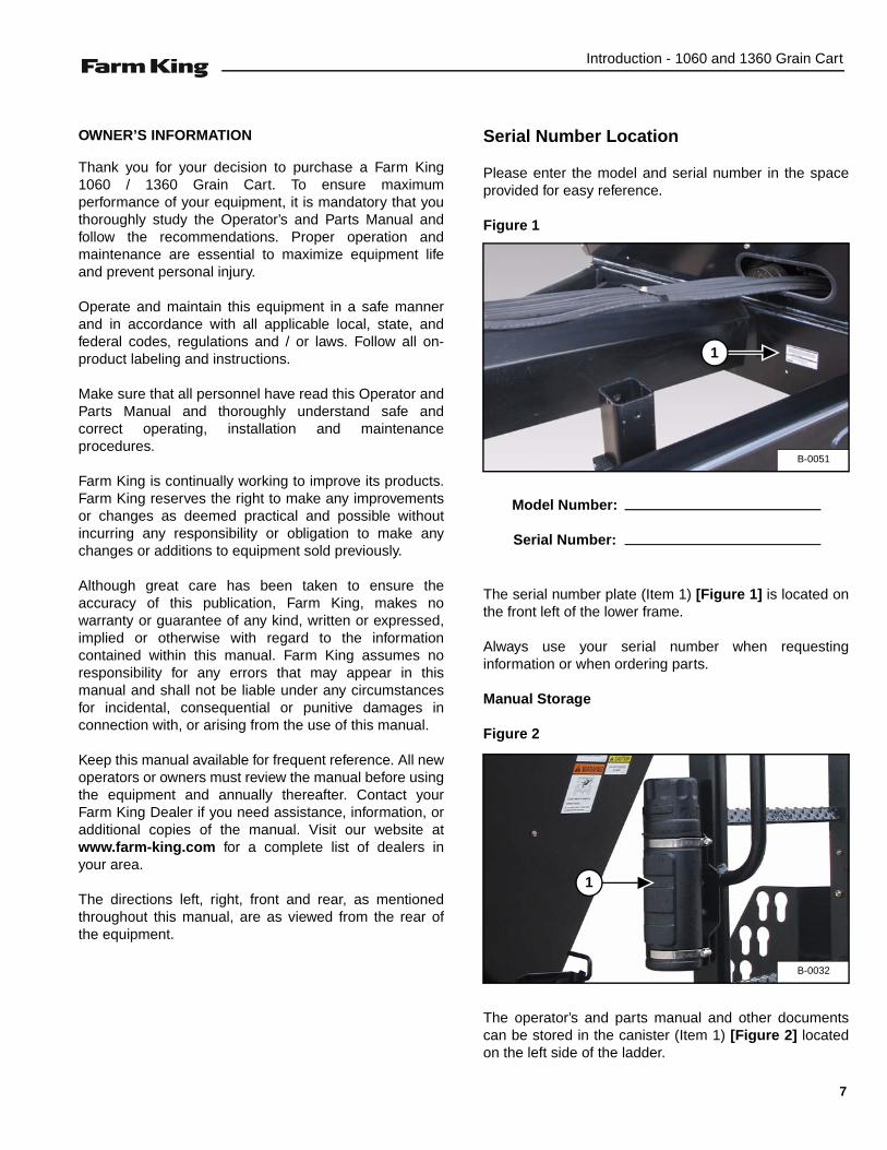
Serial Number Location
Please enter the model and serial number in the spaceprovided for easy reference.
Figure 1
The serial number plate (Item 1) [Figure 1] is located onthe front left of the lower frame.
Always use your serial number when requestinginformation or when ordering parts.
Manual Storage
Figure 2
The operator’s and parts manual and other documentscan be stored in the canister (Item 1) [Figure 2] locatedon the left side of the ladder.
B-0051
1
Model Number:
Serial Number:
B-0032
1
7

Introduction - 1060 and 1360 Grain Cart
EQUIPMENT IDENTIFICATION
Component Location
B-0031
DISCHARGE AUGER
TARP (OPTIONAL)
HYDRAULIC MOTOR
ROTATING DISCHARGE SPOUT
LADDER SIGHT GLASS
AMBER LIGHT
RED TAIL LIGHT
DISCHARGE AUGER FOLD CYLINDERCLEANOUT DOOR
8

Safety - 1060 and 1360 Grain Cart
SAFETY
SAFETY INSTRUCTIONS . . . . . . . . . . . . . . . . . . . . . . . . . . . . . . . . . . . . . . . . . . . . . . . . . . . . . . . . 11Safe Operation Is The Operator’s Responsibility . . . . . . . . . . . . . . . . . . . . . . . . . . . . . . . . . . . . 11Safe Operation Needs A Qualified Operator . . . . . . . . . . . . . . . . . . . . . . . . . . . . . . . . . . . . . . . . 11Use Safety Rules . . . . . . . . . . . . . . . . . . . . . . . . . . . . . . . . . . . . . . . . . . . . . . . . . . . . . . . . . . . . 12Transport Safety . . . . . . . . . . . . . . . . . . . . . . . . . . . . . . . . . . . . . . . . . . . . . . . . . . . . . . . . . . . . . 12Safety Rules For Power Take-Off (PTO) Driven Equipment . . . . . . . . . . . . . . . . . . . . . . . . . . . .13Machine Requirements And Capabilities . . . . . . . . . . . . . . . . . . . . . . . . . . . . . . . . . . . . . . . . . .13
FIRE PREVENTION . . . . . . . . . . . . . . . . . . . . . . . . . . . . . . . . . . . . . . . . . . . . . . . . . . . . . . . . . . . . . 14Maintenance . . . . . . . . . . . . . . . . . . . . . . . . . . . . . . . . . . . . . . . . . . . . . . . . . . . . . . . . . . . . . . . . 14Operation . . . . . . . . . . . . . . . . . . . . . . . . . . . . . . . . . . . . . . . . . . . . . . . . . . . . . . . . . . . . . . . . . . 14Starting . . . . . . . . . . . . . . . . . . . . . . . . . . . . . . . . . . . . . . . . . . . . . . . . . . . . . . . . . . . . . . . . . . . . 14Electrical . . . . . . . . . . . . . . . . . . . . . . . . . . . . . . . . . . . . . . . . . . . . . . . . . . . . . . . . . . . . . . . . . . . 14Hydraulic System . . . . . . . . . . . . . . . . . . . . . . . . . . . . . . . . . . . . . . . . . . . . . . . . . . . . . . . . . . . . 14Fueling . . . . . . . . . . . . . . . . . . . . . . . . . . . . . . . . . . . . . . . . . . . . . . . . . . . . . . . . . . . . . . . . . . . . 14Spark Arrester Exhaust System . . . . . . . . . . . . . . . . . . . . . . . . . . . . . . . . . . . . . . . . . . . . . . . . .14Welding And Grinding . . . . . . . . . . . . . . . . . . . . . . . . . . . . . . . . . . . . . . . . . . . . . . . . . . . . . . . . . 15Fire Extinguishers . . . . . . . . . . . . . . . . . . . . . . . . . . . . . . . . . . . . . . . . . . . . . . . . . . . . . . . . . . . .15
SAFETY SIGNS (DECALS) . . . . . . . . . . . . . . . . . . . . . . . . . . . . . . . . . . . . . . . . . . . . . . . . . . . . . . . 16
EQUIPMENT DECALS AND SIGNS . . . . . . . . . . . . . . . . . . . . . . . . . . . . . . . . . . . . . . . . . . . . . . . . 19
SAFETY SIGN-OFF FORM . . . . . . . . . . . . . . . . . . . . . . . . . . . . . . . . . . . . . . . . . . . . . . . . . . . . . . . 21
9

Safety - 1060 and 1360 Grain Cart
10

Safety - 1060 and 1360 Grain Cart
SAFETY INSTRUCTIONS
Safe Operation Is The Operator’s Responsibility
Safe Operation Needs A Qualified Operator
For an operator to be qualified, he or she must not usedrugs or alcoholic drinks which impair alertness orcoordination while working. An operator who is takingprescription drugs must get medical advice to determineif he or she can safely operate a machine and theequipment.
A Qualified Operator Must Do The Following:
Understand the Written Instructions, Rules andRegulations
• The written instructions from Farm King include theWarranty Registration, Dealer Inspection Report,Operator’s and Parts Manual and machine signs(decals).
• Check the rules and regulations at your location. Therules may include an employer’s work safetyrequirements. Regulations may apply to local drivingrequirements or use of a Slow Moving Vehicle (SMV)emblem. Regulations may identify a hazard such as autility line.
Have Training with Actual Operation
• Operator training must consist of a demonstration andverbal instruction. This training is given by themachine owner prior to operation.
• The new operator must start in an area withoutbystanders and use all the controls until he or she canoperate the machine safely under all conditions of thework area. Always fasten seat belt before operating.
Know the Work Conditions
• Clear working area of all bystanders, especially smallchildren and all obstacles that might be hooked orsnagged, causing injury or damage.
• Know the location of any overhead or undergroundpower lines. Call local utilities and have allunderground power lines marked prior to operation.
• Wear tight fitting clothing. Always wear safety glasseswhen doing maintenance or service.
This symbol with a warning statement means:“Warning, be alert! Your safety is involved!”Carefully read the message that follows.
Safety Alert Symbol
The signal word CAUTION on the machine and in themanuals indicates a potentially hazardous situationwhich, if not avoided, may result in minor ormoderate injury. It may also be used to alert againstunsafe practices.
The signal word DANGER on the machine and in themanuals indicates a hazardous situation which, ifnot avoided, will result in death or serious injury.
The signal word WARNING on the machine and inthe manuals indicates a potentially hazardoussituation which, if not avoided, could result in deathor serious injury.
This notice identifies procedures which must befollowed to avoid damage to the machine.
Operators must have instructions before operatingthe machine. Untrained operators can cause injuryor death.
11

Safety - 1060 and 1360 Grain Cart
SAFETY INSTRUCTIONS (CONT’D)
Use Safety Rules
• Read and follow instructions in this manual and thetractor’s Operators Manual before operating.
• Under no circumstances should young children beallowed to work with this equipment.
• This equipment is dangerous to children and personsunfamiliar with its operation.
• If the elderly are assisting with work, their physicallimitations need to be recognized andaccommodated.
• Stay clear of overhead power lines when unloadingauger is extended. Electrocution can occur withoutdirect contact.
• Check for overhead and / or underground lines beforeoperating equipment (if applicable).
• In addition to the design and configuration ofequipment, hazard control and accident preventionare dependent upon the awareness, concern,prudence and proper training of personnel involved inthe operation, transport, maintenance and storage ofequipment.
• Check that the equipment is securely fastened to thetractor / towing vehicle.
• Make sure all the machine controls are in theNEUTRAL position before starting the machine.
• Operate the equipment only from the operator’sposition.
• Operate the equipment according to the Operator’sand Parts Manual.
• When learning to operate the equipment, do it at aslow rate in an area clear of bystanders, especiallysmall children.
• DO NOT permit personnel to be in the work areawhen operating the equipment.
• The equipment must be used ONLY on approvedtractors / transport vehicles.
• DO NOT modify the equipment in any way.Unauthorized modification may impair the functionand / or safety and could affect the life of theequipment.
• DO NOT make any adjustments or repairs on theequipment while the machine is running.
• Keep shields and guards in place. Replace ifdamaged.
Transport Safety
• Do not exceed 20 mph (32 kph). Reduce speed onrough roads and surfaces.
• Comply with state and local laws governing highwaysafety and movement of machinery on public roads.
• The use of flashing amber lights is acceptable in mostlocalities. However, some localities prohibit their use.Local laws should be checked for all highway lightingand marking requirements.
• Always install transport locks, pins or brackets beforetransporting.
• Always yield to oncoming traffic in all situations andmove to the side of the road so any following trafficmay pass.
• Always enter curves or drive up or down hills at a lowspeed and at a gradual steering angle.
• Never allow riders on either tractor or equipment.
• Keep tractor / towing vehicle in a lower gear at alltimes when traveling down steep grades.
• Maintain proper brake settings at all times (ifequipped).
• Stay away from overhead power lines whenunloading auger is extended. Electrocution can occurwithout direct contact.
12
Safety - 1060 and 1360 Grain Cart
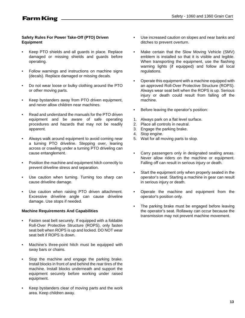
Safety Rules For Power Take-Off (PTO) Driven Equipment
• Keep PTO shields and all guards in place. Replacedamaged or missing shields and guards beforeoperating.
• Follow warnings and instructions on machine signs(decals). Replace damaged or missing decals.
• Do not wear loose or bulky clothing around the PTOor other moving parts.
• Keep bystanders away from PTO driven equipment,and never allow children near machines.
• Read and understand the manuals for the PTO drivenequipment and be aware of safe operatingprocedures and hazards that may not be readilyapparent.
• Always walk around equipment to avoid coming neara turning PTO driveline. Stepping over, leaningacross or crawling under a turning PTO driveling cancause entanglement.
• Position the machine and equipment hitch correctly toprevent driveline stress and separation.
• Use caution when turning. Turning too sharp cancause driveline damage.
• Use caution when raising PTO driven attachment.Excessive driveline angle can cause drivelinedamage. Use stops if needed.
Machine Requirements And Capabilities
• Fasten seat belt securely. If equipped with a foldableRoll-Over Protective Structure (ROPS), only fastenseat belt when ROPS is up and locked. DO NOT wearseat belt if ROPS is down.
• Machine’s three-point hitch must be equipped withsway bars or chains.
• Stop the machine and engage the parking brake.Install blocks in front of and behind the rear tires of themachine. Install blocks underneath and support theequipment securely before working under raisedequipment.
• Keep bystanders clear of moving parts and the workarea. Keep children away.
• Use increased caution on slopes and near banks andditches to prevent overturn.
• Make certain that the Slow Moving Vehicle (SMV)emblem is installed so that it is visible and legible.When transporting the equipment, use the flashingwarning lights (if equipped) and follow all localregulations.
• Operate this equipment with a machine equipped withan approved Roll-Over Protective Structure (ROPS).Always wear seat belt when the ROPS is up. Seriousinjury or death could result from falling off themachine.
• Before leaving the operator’s position:
1. Always park on a flat level surface.2. Place all controls in neutral.3. Engage the parking brake.4. Stop engine.5. Wait for all moving parts to stop.
• Carry passengers only in designated seating areas.Never allow riders on the machine or equipment.Falling off can result in serious injury or death.
• Start the equipment only when properly seated in theoperator’s seat. Starting a machine in gear can resultin serious injury or death.
• Operate the machine and equipment from theoperator's position only.
• The parking brake must be engaged before leavingthe operator’s seat. Rollaway can occur because thetransmission may not prevent machine movement.
13

Safety - 1060 and 1360 Grain Cart
FIRE PREVENTION
Maintenance
The machine and some equipment have componentsthat are at high temperatures under normal operatingconditions. The primary source of high temperatures isthe engine and exhaust system. The electrical system, ifdamaged or incorrectly maintained, can be a source ofarcs or sparks.
Flammable debris (leaves, straw, etc.) must be removedregularly. If flammable debris is allowed to accumulate, itcan cause a fire hazard. Clean often to avoid thisaccumulation. Flammable debris in the enginecompartment is a potential fire hazard.
The operator’s area, engine compartment and enginecooling system must be inspected every day and cleanedif necessary to prevent fire hazards and overheating.
All fuels, most lubricants and some coolant mixtures areflammable. Flammable fluids that are leaking or spilledonto hot surfaces or onto electrical components cancause a fire.
Operation
The Farm King machine must be in good operatingcondition before use.
Check all of the items listed on the service scheduleunder the 8 hour column. (See “SERVICE SCHEDULE”on page 41.)
Do not use the machine where exhaust, arcs, sparks orhot components can contact flammable material,explosive dust or gases.
Starting
Do not use ether or starting fluids on any engine that hasglow plugs. These starting aids can cause explosion andinjure you or bystanders.
Use the procedure in the tractor’s operator’s manual forconnecting the battery and for jump starting.
Electrical
Check all electrical wiring and connections for damage.Keep the battery terminals clean and tight. Repair orreplace any damaged part or wires that are loose orfrayed.
Battery gas can explode and cause serious injury. Do notjump start or charge a frozen or damaged battery. Keepany open flames or sparks away from batteries. Do notsmoke in battery charging area.
Hydraulic System
Check hydraulic tubes, hoses and fittings for damageand leakage. Never use open flame or bare skin to checkfor leaks. Hydraulic tubes and hoses must be properlyrouted and have adequate support and secure clamps.Tighten or replace any parts that show leakage.
Always clean fluid spills. Do not use gasoline or dieselfuel for cleaning parts. Use commercial nonflammablesolvents.
Fueling
Stop the engine and let it cool before adding fuel. Nosmoking! Do not refuel a machine near open flames orsparks. Fill the fuel tank outdoors.
Spark Arrester Exhaust System
The spark arrester exhaust system is designed to controlthe emission of hot particles from the engine and exhaustsystem, but the muffler and the exhaust gases are stillhot.
Check the spark arrester exhaust system regularly tomake sure it is maintained and working properly. Use theprocedure in the machine’s Operator’s Manual forcleaning the spark arrester muffler (if equipped).
14
Safety - 1060 and 1360 Grain Cart
FIRE PREVENTION (CONT’D)
Welding And Grinding
Always clean the machine and equipment, disconnectthe battery, and disconnect the wiring from the machinecontrols before welding. Cover rubber hoses, battery andall other flammable parts. Keep a fire extinguisher nearthe machine when welding.
Have good ventilation when grinding or welding paintedparts. Wear dust mask when grinding painted parts.Toxic dust or gas can be produced.
Dust generated from repairing nonmetallic parts such ashoods, fenders or covers can be flammable or explosive.Repair such components in a well ventilated area awayfrom open flames or sparks.
Fire Extinguishers
Know where fire extinguishers and first aid kits arelocated and how to use them. Inspect the fireextinguisher and service the fire extinguisher regularly.Obey the recommendations on the instructions plate.
15
Safety - 1060 and 1360 Grain Cart
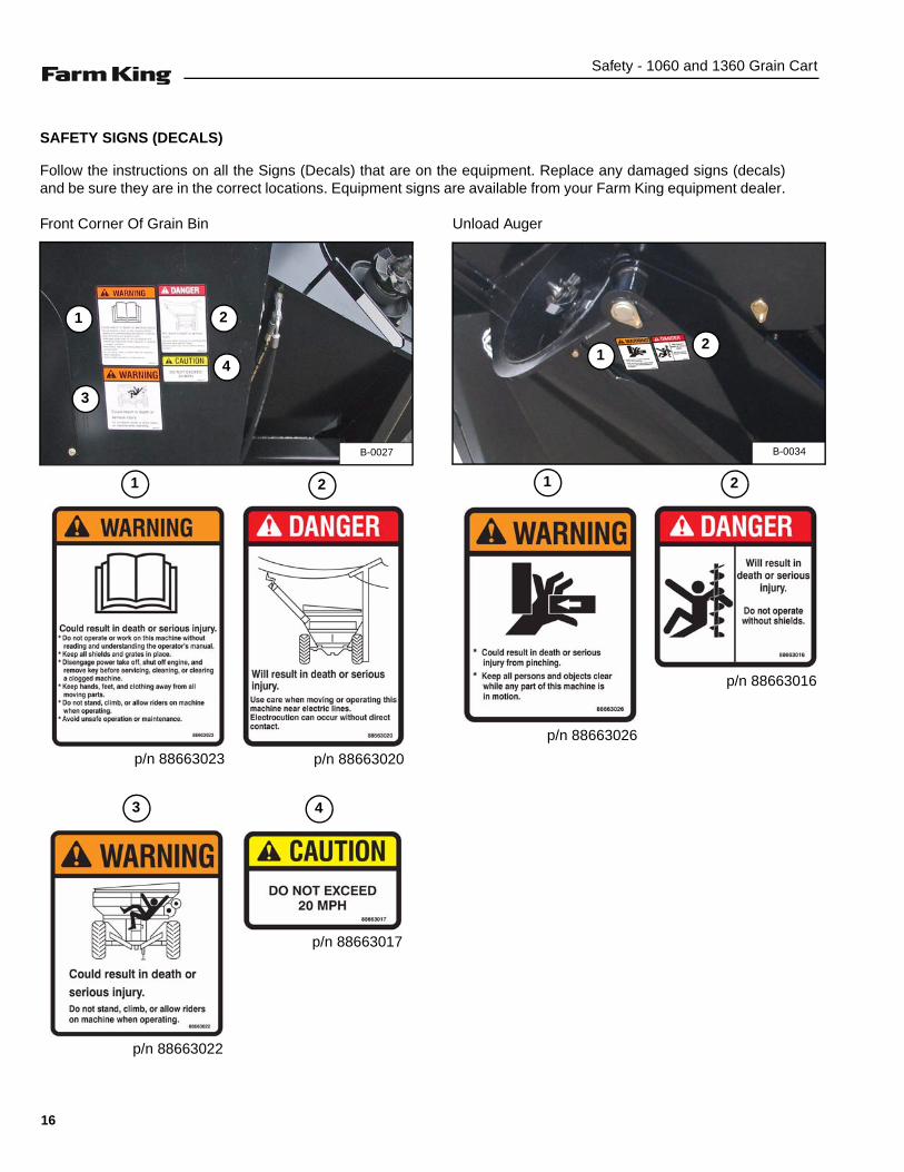
SAFETY SIGNS (DECALS)
Follow the instructions on all the Signs (Decals) that are on the equipment. Replace any damaged signs (decals)and be sure they are in the correct locations. Equipment signs are available from your Farm King equipment dealer.
Front Corner Of Grain Bin Unload Auger
B-0027
1 2
3
4
1 2
43
p/n 88663023 p/n 88663020
p/n 88663017
p/n 88663022
B-0034
12
1 2
p/n 88663026
p/n 88663016
16

Safety - 1060 and 1360 Grain Cart
Main PTO Driveline Main PTO Driveline (Under guard at rear of driveline)
Front / Top Of Bin (Right of the ladder)
B-0039
1 2
1
p/n 88661272
p/n 88661274
2
Decal # 88661274 islocated on the actualdrive shaft under theplastic guard.
B-0028
1
1
p/n 88663015
B-0038
1 2
1
p/n 88663021
2
p/n 88663016
17
Safety - 1060 and 1360 Grain Cart
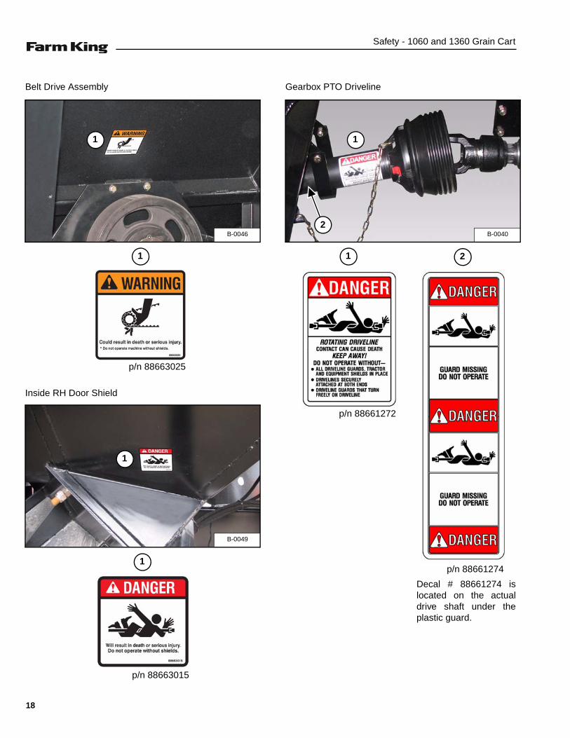
Belt Drive Assembly
Inside RH Door Shield
Gearbox PTO Driveline
B-0046
1
1
p/n 88663025
B-0049
1
1
p/n 88663015
B-0040
1
2
1
p/n 88661272
p/n 88661274
2
Decal # 88661274 islocated on the actualdrive shaft under theplastic guard.
18

Safety - 1060 and 1360 Grain Cart
Front Drive Shaft (Under guard behind PTO Driveline) EQUIPMENT DECALS AND SIGNS
NOTE: All safety related decals are shown in theSafety Signs Section. (See “SAFETY SIGNS(DECALS)” on page 16.)
Check and replace any worn, torn, hard to read ormissing decals on your equipment.
Part Number 88663100
Part Number 8866310
Part Number 88663102
Part Number 88663103
B-0055
1
1
p/n 88663014
19

Safety - 1060 and 1360 Grain Cart
Part Number 88662287 (Left Side)Part Number 88665644 (Left Side) (Black)
Part Number 88662288 (Right Side)Part Number 88665645 (Right Side) (Black)
Part Number 88662289 (Left Side)Part Number 88665646 (Left Side) (Black)
Part Number 88662290 (Right Side)Part Number 88665647 (Right Side) (Black)
Part Number 88662291 (Left Side)Part Number 88665648 (Left Side) (Black)
Part Number 88662292 (Right Side)Part Number 88665649 (Right Side) (Black)
Part Number 88662293 (Left Side)Part Number 88665650 (Left Side) (Black)
Part Number 88662294 (Right Side)Part Number 88665651 (Right Side) (Black)
Part Number 88662295 (Rear)Part Number 88665652 (Rear) (Black)
Part Number SX17 - 5910B (Amber)
Part Number SX17 - 5915B (Red)
Part Number SX17 - 5920B (Day Orange)
Part Number 88661041 (Tandem Axle)
Tarp Instruction Decal (Supplied with tarp)
20
Safety - 1060 and 1360 Grain Cart
SAFETY SIGN-OFF FORM
Farm King follows the general Safety Standards specified by the American Society of Agricultural and BiologicalEngineers (ASABE) and the Occupational Safety and Health Administration (OSHA). Anyone who will be operating and /or maintaining the 1060 and 1360 grain cart must read and clearly understand ALL Safety, Operating and Maintenanceinformation presented in this manual.
Annually review this information before the season start-up and make these periodic reviews of SAFETY andOPERATION a standard practice for all of your equipment. An untrained operator is unqualified to operate thismachine.
The following sign-off sheet is provided for your record and to show that all personnel who will be working with theequipment have read and understand the information in this Operator’s and Parts Manual and have been instructed in theoperation of the equipment.
SIGN-OFF SHEET
Date Employee’s Signature Employer’s Signature
Instructions are necessary before operating or servicing equipment. Read and understand theOperator’s and Parts Manual and safety signs (decals) on equipment. Follow warnings andinstructions in the manuals when making repairs, adjustments or servicing. Check for correctfunction after adjustments, repairs or service. Untrained operators and failure to follow instructionscan cause injury or death.
21

Safety - 1060 and 1360 Grain Cart
22

Operation - 1060 and 1360 Grain Cart
OPERATION
GENERAL INFORMATION . . . . . . . . . . . . . . . . . . . . . . . . . . . . . . . . . . . . . . . . . . . . . . . . . . . . . . . 25Pre - Operation Checklist . . . . . . . . . . . . . . . . . . . . . . . . . . . . . . . . . . . . . . . . . . . . . . . . . . . . . . 25Break - In Checklist . . . . . . . . . . . . . . . . . . . . . . . . . . . . . . . . . . . . . . . . . . . . . . . . . . . . . . . . . . . 26Tractor Requirements . . . . . . . . . . . . . . . . . . . . . . . . . . . . . . . . . . . . . . . . . . . . . . . . . . . . . . . . . 27Entering And Leaving The Operator’s Position . . . . . . . . . . . . . . . . . . . . . . . . . . . . . . . . . . . . . . 27
INITIAL SET-UP . . . . . . . . . . . . . . . . . . . . . . . . . . . . . . . . . . . . . . . . . . . . . . . . . . . . . . . . . . . . . . . . 28Connecting The Grain Cart To The Tractor . . . . . . . . . . . . . . . . . . . . . . . . . . . . . . . . . . . . . . . . . 28Connecting The PTO Driveline . . . . . . . . . . . . . . . . . . . . . . . . . . . . . . . . . . . . . . . . . . . . . . . . . . 29Connecting Hydraulic Hoses . . . . . . . . . . . . . . . . . . . . . . . . . . . . . . . . . . . . . . . . . . . . . . . . . . . . 30Connecting Electrical Harness . . . . . . . . . . . . . . . . . . . . . . . . . . . . . . . . . . . . . . . . . . . . . . . . . . 30
GRAIN CART OPERATION . . . . . . . . . . . . . . . . . . . . . . . . . . . . . . . . . . . . . . . . . . . . . . . . . . . . . . . 31Loading The Grain Cart . . . . . . . . . . . . . . . . . . . . . . . . . . . . . . . . . . . . . . . . . . . . . . . . . . . . . . . 31Unloading With Discharge Auger . . . . . . . . . . . . . . . . . . . . . . . . . . . . . . . . . . . . . . . . . . . . . . . . 33Unloading Through Dump Door . . . . . . . . . . . . . . . . . . . . . . . . . . . . . . . . . . . . . . . . . . . . . . . . .35
TRANSPORTING . . . . . . . . . . . . . . . . . . . . . . . . . . . . . . . . . . . . . . . . . . . . . . . . . . . . . . . . . . . . . . . 36Requirements . . . . . . . . . . . . . . . . . . . . . . . . . . . . . . . . . . . . . . . . . . . . . . . . . . . . . . . . . . . . . . .36Transporting Guidelines . . . . . . . . . . . . . . . . . . . . . . . . . . . . . . . . . . . . . . . . . . . . . . . . . . . . . . . 36
23

Operation - 1060 and 1360 Grain Cart
24

Operation - 1060 and 1360 Grain Cart
GENERAL INFORMATION
Pre - Operation Checklist
Before operating the grain cart for the first time and eachtime thereafter, check the following items:
1. Lubricate the equipment per the schedule outline inthe Maintenance Section. (See “SERVICESCHEDULE” on page 41.)
2. Check the grain cart hitch for damaged, loose ormissing parts. Repair as needed before operation.
3. Check the tension and alignment of the belt. Adjusttension and align as required. (See “Adjusting BeltTension” on page 46.)
4. Check the augers. Remove any twine, wire or othermaterial that has become entangled.
5. Check that all bearings turn freely. Replace any thatare rough or seized.
6. Make sure that all guards and shields are in place,secured and functioning as designed.
7. Check condition of all hydraulic components for leaks.Repair as required.
NOTE: Do not operate with hydraulic leaks.
8. Check that the PTO drivelines telescope easily andturns freely.
9. Check the oil level in the gearbox. (See Figure 27 onpage 44.)
AVOID INJURY OR DEATH
• Disengage the PTO, engage the machine’sparking brake, stop the engine and make sure allrotating components are completely stoppedbefore connecting, disconnecting, adjusting orcleaning any PTO driven equipment.
• Always keep PTO shields and all guards in placewhen using PTO driven equipment.
• Disengage PTO for road travel.
• Keep hands, feet and clothing away.
AVOID INJURY OR DEATH
Wear safety glasses to prevent eye injury when anyof the following conditions exist:
• When fluids are under pressure.
• Flying debris or loose material is present.
• Engine is running.
• Tools are being used.
Leaking fluids under pressure can enter the skinand cause serious injury or death. Immediatemedical attention is required. Wear goggles. Usecardboard to check for leaks.
25
Operation - 1060 and 1360 Grain Cart
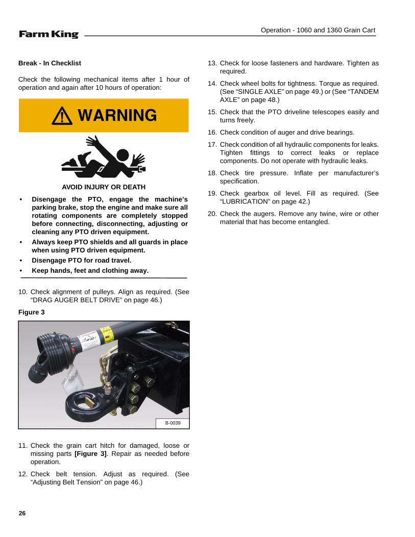
Break - In Checklist
Check the following mechanical items after 1 hour ofoperation and again after 10 hours of operation:
10. Check alignment of pulleys. Align as required. (See“DRAG AUGER BELT DRIVE” on page 46.)
Figure 3
11. Check the grain cart hitch for damaged, loose ormissing parts [Figure 3]. Repair as needed beforeoperation.
12. Check belt tension. Adjust as required. (See“Adjusting Belt Tension” on page 46.)
13. Check for loose fasteners and hardware. Tighten asrequired.
14. Check wheel bolts for tightness. Torque as required.(See “SINGLE AXLE” on page 49.) or (See “TANDEMAXLE” on page 48.)
15. Check that the PTO driveline telescopes easily andturns freely.
16. Check condition of auger and drive bearings.
17. Check condition of all hydraulic components for leaks.Tighten fittings to correct leaks or replacecomponents. Do not operate with hydraulic leaks.
18. Check tire pressure. Inflate per manufacturer’sspecification.
19. Check gearbox oil level. Fill as required. (See“LUBRICATION” on page 42.)
20. Check the augers. Remove any twine, wire or othermaterial that has become entangled.
AVOID INJURY OR DEATH
• Disengage the PTO, engage the machine’sparking brake, stop the engine and make sure allrotating components are completely stoppedbefore connecting, disconnecting, adjusting orcleaning any PTO driven equipment.
• Always keep PTO shields and all guards in placewhen using PTO driven equipment.
• Disengage PTO for road travel.
• Keep hands, feet and clothing away.
B-0039
26

Operation - 1060 and 1360 Grain Cart
Tractor Requirements
The 1060 grain cart will require a MFWD (MechanicalFront Wheel Drive) tractor (minimum 275 hp), threeauxiliary hydraulic functions, Category IV rated drawbarand a 7-Pin electrical connection.
The 1360 grain cart will require a 4WD tractor (minimum275 hp), PTO shaft, three auxiliary hydraulic functions,Category V rated drawbar and a 7-Pin electricalconnection.
The tractor must be equipped with a 20 - spline, 1-3/4inch (44.5 mm) PTO shaft when used with the Grain Cart.
Drawbar Adjustment
Figure 4
Adjust the tractor’s drawbar in / out, until the center of thehitch pin hole (Item 1) [Figure 4] is 16 inches (410 mm)from the end of the tractor’s PTO shaft. See your tractor’sowner’s manual for correct adjustment procedures.
Entering And Leaving The Operator’s Position
Entering The Operator’s Position
Move to the operator’s position, start the engine andrelease the parking brake.
Leaving The Operator’s Position
Park the tractor / equipment on a flat level surface.
Place all controls in neutral, engage the park brake, stopthe engine and wait for all moving parts to stop. Leave theoperator’s position.
• Do NOT exceed 1000 RPM PTO.• Keep PTO shields and all guards in place.• Keep away from moving parts.• Keep bystanders away.
B-0001
16 in.(410 mm)
1
Follow the instructions in your tractor’s operationmanual for the correct procedure.
AVOID INJURY OR DEATHBefore you leave the operator’s position:• Always park on a flat level surface.• Place all controls in NEUTRAL.• Engage the park brake.• Stop the engine and remove the key.• Wait for all moving parts to stop.
27

Operation - 1060 and 1360 Grain Cart
INITIAL SET-UP
Connecting The Grain Cart To The Tractor
Always inspect the tractor’s drawbar and grain cart hitchbefore connecting. See the tractor’s owner’s manual.
Verify that the tractor’s drawbar is adjusted correctly foruse with the grain cart. (See “Drawbar Adjustment” onpage 27.)
Enter the operator’s position. (See “Entering TheOperator’s Position” on page 27.)
Move the tractor into position in front of the grain cart.
Move the tractor backwards, aligning the drawbar with thegrain cart hitch.
NOTE: The jack may need to be lowered or raised forproper alignment of the drawbar and hitch.
If the grain cart hitch needs to be adjusted, stop thetractor when drawbar is just in front of the grain cart hitch.
Leave the operator’s position. (See “Leaving TheOperator’s Position” on page 27.)
Figure 5
Turn the handle (Item 1) [Figure 5] clockwise to raise thehitch or counterclockwise to lower the hitch.
Lower or raise the grain cart hitch until aligned with thetractor’s drawbar.
Move to the operator’s seat, start the engine and releasethe parking brake.
Move the tractor backwards, aligning the drawbar hitchpin hole with the grain cart hitch pin hole(s).
Stop the tractor and leave operator’s position.
NOTE: Always use a hitch pin of adequate size andstrength and a retaining pin with a lockingdevice.
AVOID INJURY OR DEATHBefore moving the tractor, look in all directions andmake sure no bystanders, especially small childrenare in the work area. Do not allow anyone betweenthe tractor and the equipment when backing up tothe equipment for connecting.
B-0056
1
AVOID INJURY OR DEATHKeep fingers and hands out of pinch points whenconnecting and disconnecting equipment.
28
Operation - 1060 and 1360 Grain Cart
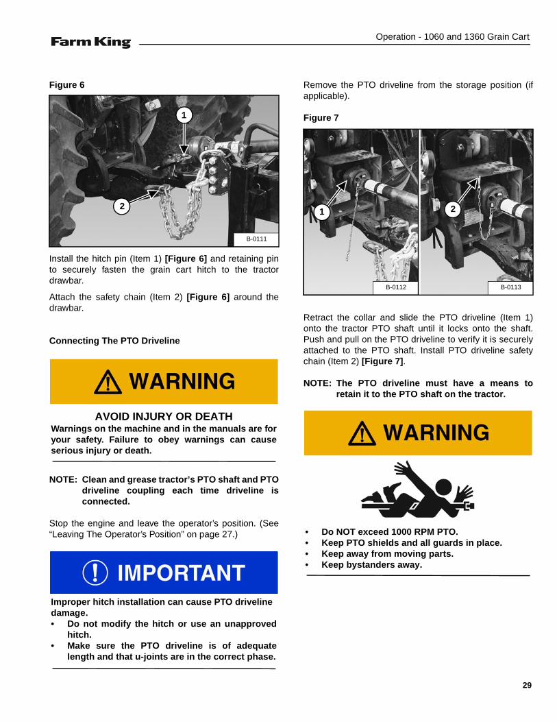
Figure 6
Install the hitch pin (Item 1) [Figure 6] and retaining pinto securely fasten the grain cart hitch to the tractordrawbar.
Attach the safety chain (Item 2) [Figure 6] around thedrawbar.
Connecting The PTO Driveline
NOTE: Clean and grease tractor’s PTO shaft and PTOdriveline coupling each time driveline isconnected.
Stop the engine and leave the operator’s position. (See“Leaving The Operator’s Position” on page 27.)
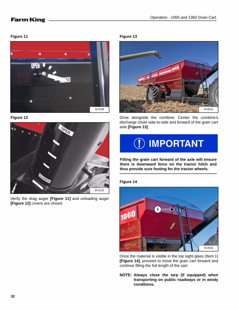
Remove the PTO driveline from the storage position (ifapplicable).
Figure 7
Retract the collar and slide the PTO driveline (Item 1)onto the tractor PTO shaft until it locks onto the shaft.Push and pull on the PTO driveline to verify it is securelyattached to the PTO shaft. Install PTO driveline safetychain (Item 2) [Figure 7].
NOTE: The PTO driveline must have a means toretain it to the PTO shaft on the tractor.
B-0111
1
2
AVOID INJURY OR DEATHWarnings on the machine and in the manuals are foryour safety. Failure to obey warnings can causeserious injury or death.
Improper hitch installation can cause PTO drivelinedamage.• Do not modify the hitch or use an unapproved
hitch.• Make sure the PTO driveline is of adequate
length and that u-joints are in the correct phase.
B-0113B-0112
1 2
• Do NOT exceed 1000 RPM PTO.• Keep PTO shields and all guards in place.• Keep away from moving parts.• Keep bystanders away.
29

Operation - 1060 and 1360 Grain Cart
Connecting Hydraulic Hoses
NOTE: Make sure the quick couplers are fullyengaged. If the quick couplers do not fullyengage, check to see that the couplers are thesame size and type.
To Connect:
Figure 8
Pull back on the collar of the female coupler, pushcouplers together, release the collar when the couplersare fully engaged and locked [Figure 8].
1. First Circuit: Discharge auger door and drag augergate cylinders.
2. Second Circuit: Auger chute cylinder.
3. Third Circuit: Auger fold cylinder.
To Disconnect:
Pull back on the collar and pull the male coupler out todisconnect.
Connecting Electrical Harness
Connect the grain cart’s electrical harness (Item 4)[Figure 8] to the tractor’s electrical system.
Lower jack until weight of equipment is resting on tractordrawbar. Pull lock pin on jack and remove. Mount jack tostorage bracket and secure with lock pin.
HIGH PRESSURE FLUID HAZARD
To prevent serious injury or death from highpressure fluid:
• Relieve pressure on system before repairing oradjusting.
• Wear proper hand and eye protection whensearching for leaks. Use wood or cardboardinstead of hands.
• Keep all components in good repair.
• Contain and dispose of any oil leakage in anenvironmentally safe manner.
• Thoroughly clean the quick couplers beforemaking connections. Dirt can quickly damagethe system.
B-0035
1
2
3
4
AVOID BURNS
Hydraulic fluid, tubes, fittings and quick couplerscan get hot when running equipment. Be carefulwhen connecting and disconnecting quick couplers.
30

Operation - 1060 and 1360 Grain Cart
GRAIN CART OPERATION
Loading The Grain Cart
Figure 9
Open tarp (if equipped) [Figure 9].
Figure 10
Place the crank arm (Item 1) in the crank retainer (Item 2)[Figure 10] after closing or opening the tarp.
MACHINE TIPPING OR ROLL OVER CAN CAUSE SERIOUS INJURY OR DEATH
• Turn on level ground. Slow down when turning.• Go up and down slopes, not across them.• Keep the heavy end of the machine uphill.• Do not overload the machine.• Check for adequate traction.
RUN - AWAY HAZARD
To prevent serious injury or death:
• Shift to lower gear before going down steepgrades.
• Keep tractor / towing vehicle in gear at all times.• Never exceed 20 mph (32 kph).
B-0012
B-0057
1
2
31
Operation - 1060 and 1360 Grain Cart
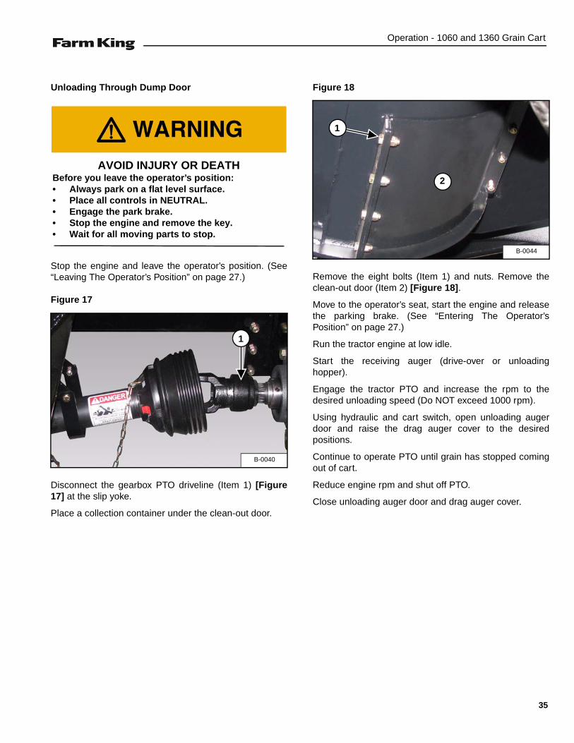
Figure 11
Figure 12
Verify the drag auger [Figure 11] and unloading auger[Figure 12] covers are closed.
Figure 13
Drive alongside the combine. Center the combine’sdischarge chute side-to-side and forward of the grain cartaxle [Figure 13].
Figure 14
Once the material is visible in the top sight glass (Item 1)[Figure 14], proceed to move the grain cart forward andcontinue filling the full length of the cart.
NOTE: Always close the tarp (if equipped) whentransporting on public roadways or in windyconditions.
B-0109
B-0110
B-0015
Filling the grain cart forward of the axle will ensurethere is downward force on the tractor hitch andthus provide sure footing for the tractor wheels.
B-0016
1
32

Operation - 1060 and 1360 Grain Cart
Unloading With Discharge Auger
Drive to the unloading location.
Open the tarp (if equipped).
Run the tractor engine at low idle.
Figure 15
Extend the unload auger into it’s fully raised position[Figure 15].
Figure 16
Position the unload auger over receiving container[Figure 16].
Slowly engage the tractor PTO, increase engine rpm torated PTO speed.
Slowly open the discharge auger door.
NOTE: Once the discharge auger door cylinder isfully extended, the drag auger cover will openusing the same tractor hydraulic controlfunction.
ELECTROCUTION HAZARDTo prevent serious injury or death fromelectrocution:
• Be aware of overhead powerlines.• Keep away from powerlines when transporting
or raising discharge auger.• Electrocution can occur without direct contact.
B-0013
B-0010
Starting a discharge auger when full of grain maycause damage to the drive system.
• Do NOT exceed 1000 RPM PTO.• Keep PTO shields and all guards in place.• Keep away from moving parts.• Keep bystanders away.
33

Operation - 1060 and 1360 Grain Cart
Move the grain cart or use the discharge chute todistribute grain centrally and evenly in the receivingcontainer.
NOTE: When discharging into a trailer, always fillfront to rear.
Run the PTO until all the material in the grain cart isremoved or the truck is full.
Use the tractor hydraulic control function to close thedrag auger gate first and then the discharge auger door.
Continue to run PTO until discharge auger is empty.
Reduce engine speed to low idle and disengage PTO.
Fully lower the discharge auger into the transportposition.
Move the tractor and grain cart to the loading area,alongside the combine.
When the receiving container is getting close to fulland the grain cart is not empty, close the dischargeauger door and run the PTO until the dischargeauger is empty before disengaging the tractor PTO.
34
Operation - 1060 and 1360 Grain Cart
Unloading Through Dump Door
Stop the engine and leave the operator’s position. (See“Leaving The Operator’s Position” on page 27.)
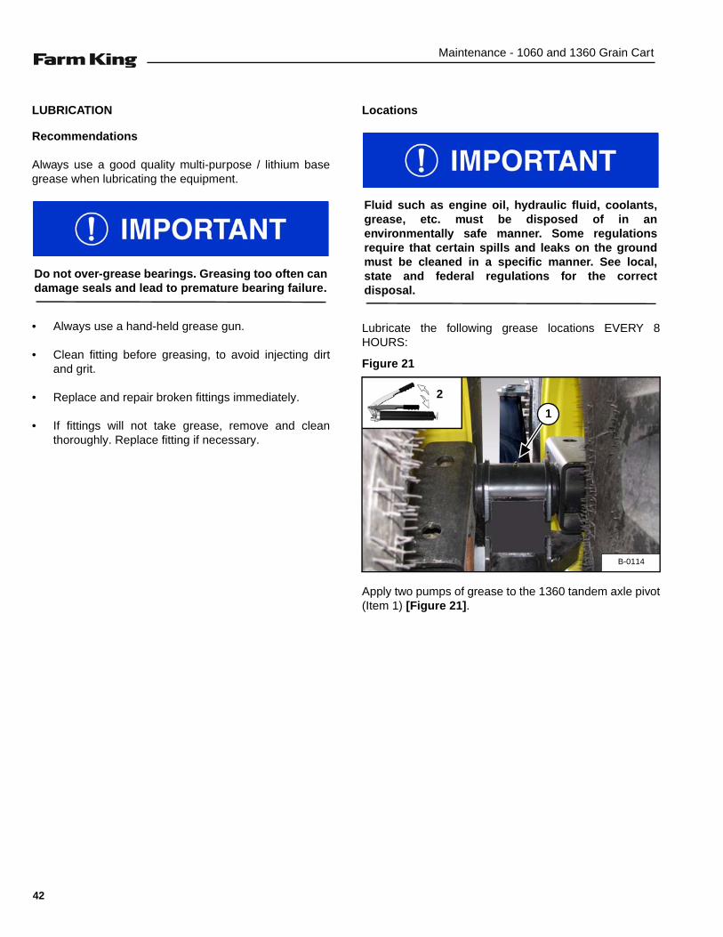
Figure 17
Disconnect the gearbox PTO driveline (Item 1) [Figure17] at the slip yoke.
Place a collection container under the clean-out door.
Figure 18
Remove the eight bolts (Item 1) and nuts. Remove theclean-out door (Item 2) [Figure 18].
Move to the operator’s seat, start the engine and releasethe parking brake. (See “Entering The Operator’sPosition” on page 27.)
Run the tractor engine at low idle.
Start the receiving auger (drive-over or unloadinghopper).
Engage the tractor PTO and increase the rpm to thedesired unloading speed (Do NOT exceed 1000 rpm).
Using hydraulic and cart switch, open unloading augerdoor and raise the drag auger cover to the desiredpositions.
Continue to operate PTO until grain has stopped comingout of cart.
Reduce engine rpm and shut off PTO.
Close unloading auger door and drag auger cover.
AVOID INJURY OR DEATHBefore you leave the operator’s position:• Always park on a flat level surface.• Place all controls in NEUTRAL.• Engage the park brake.• Stop the engine and remove the key.• Wait for all moving parts to stop.
B-0040
1
B-0044
1
2
35

Operation - 1060 and 1360 Grain Cart
TRANSPORTING
Requirements
Comply with federal, state, local and provincial lawsregarding the transport of farm equipment on pubicroadways.
Verify that the tractor / tow vehicle are approved fortransporting the equipment and that the equipment issecurely attached to the tractor / tow vehicle.
Verify safety chain is installed and properly connectedbefore transporting equipment.
Verify that the SMV (Slow Moving Vehicle) emblem, alllights and reflectors are clean and visible.
Figure 19
Lower the discharge auger into the transport position[Figure 19].
Figure 20
Verify that the unload auger is resting in the augersupport bracket (Item 1) [Figure 20] before transporting.
Transporting Guidelines
The ratio of the tractor / tow vehicle weight to the loadedequipment weight plays an important role in definingacceptable travel speed.
TRAVEL SPEED - Acceptable travel speed.
WEIGHT RATIO - Weight of fully equipped or loadedimplement(s) relative to weight of tractor / tow vehicle.
Never exceed 20 mph (32 kph).
Use of an unapproved hitch or tractor / tow vehiclecan result in loss of control, leading to seriousinjury or death.
Tractor / tow vehicle and hitch must have the ratedcapacity to tow equipment.
B-0017
TRAVEL SPEED WEIGHT RATIO
Up to 20 mph (32 kph) 1 to 1 (or less)
Up to 10 mph (16 kph) 2 to 1 (or less)
DO NOT TOW More than 2 to 1
B-0058
1
Do not move or transport the grain cart unlessdischarge auger is supported on the auger supportbracket.
AVOID SERIOUS INJURY OR DEATH
DO NOT transport a loaded grain cart on publicroadways. Excess weight will greatly increasetractor stopping distance and may cause theoperator to lose control of the tractor or tow vehicle.
36

Maintenance - 1060 and 1360 Grain Cart
MAINTENANCE
TROUBLESHOOTING . . . . . . . . . . . . . . . . . . . . . . . . . . . . . . . . . . . . . . . . . . . . . . . . . . . . . . . . . . . 39Chart . . . . . . . . . . . . . . . . . . . . . . . . . . . . . . . . . . . . . . . . . . . . . . . . . . . . . . . . . . . . . . . . . . . . . . 39
SERVICE SCHEDULE . . . . . . . . . . . . . . . . . . . . . . . . . . . . . . . . . . . . . . . . . . . . . . . . . . . . . . . . . . . 41Maintenance Intervals . . . . . . . . . . . . . . . . . . . . . . . . . . . . . . . . . . . . . . . . . . . . . . . . . . . . . . . . . 41
LUBRICATION . . . . . . . . . . . . . . . . . . . . . . . . . . . . . . . . . . . . . . . . . . . . . . . . . . . . . . . . . . . . . . . . . 42Recommendations . . . . . . . . . . . . . . . . . . . . . . . . . . . . . . . . . . . . . . . . . . . . . . . . . . . . . . . . . . . 42Locations . . . . . . . . . . . . . . . . . . . . . . . . . . . . . . . . . . . . . . . . . . . . . . . . . . . . . . . . . . . . . . . . . . . 42
DRAG AUGER BELT DRIVE . . . . . . . . . . . . . . . . . . . . . . . . . . . . . . . . . . . . . . . . . . . . . . . . . . . . . . 46Adjusting Belt Tension . . . . . . . . . . . . . . . . . . . . . . . . . . . . . . . . . . . . . . . . . . . . . . . . . . . . . . . . . 46
PTO DRIVELINE . . . . . . . . . . . . . . . . . . . . . . . . . . . . . . . . . . . . . . . . . . . . . . . . . . . . . . . . . . . . . . .47Removal . . . . . . . . . . . . . . . . . . . . . . . . . . . . . . . . . . . . . . . . . . . . . . . . . . . . . . . . . . . . . . . . . . . 47Disassembly And Assembly . . . . . . . . . . . . . . . . . . . . . . . . . . . . . . . . . . . . . . . . . . . . . . . . . . . . 47Cleaning And Inspection . . . . . . . . . . . . . . . . . . . . . . . . . . . . . . . . . . . . . . . . . . . . . . . . . . . . . . . 47
TANDEM AXLE . . . . . . . . . . . . . . . . . . . . . . . . . . . . . . . . . . . . . . . . . . . . . . . . . . . . . . . . . . . . . . . . 48Wheel Lug Nut Torque . . . . . . . . . . . . . . . . . . . . . . . . . . . . . . . . . . . . . . . . . . . . . . . . . . . . . . . .48Inner Tire Access . . . . . . . . . . . . . . . . . . . . . . . . . . . . . . . . . . . . . . . . . . . . . . . . . . . . . . . . . . . . 48
SINGLE AXLE . . . . . . . . . . . . . . . . . . . . . . . . . . . . . . . . . . . . . . . . . . . . . . . . . . . . . . . . . . . . . . . . . 49Wheel Lug Nut Torque . . . . . . . . . . . . . . . . . . . . . . . . . . . . . . . . . . . . . . . . . . . . . . . . . . . . . . . .49
SAFETY SIGN (DECAL) INSTALLATION . . . . . . . . . . . . . . . . . . . . . . . . . . . . . . . . . . . . . . . . . . . . 49Procedure . . . . . . . . . . . . . . . . . . . . . . . . . . . . . . . . . . . . . . . . . . . . . . . . . . . . . . . . . . . . . . . . . . 49
STORAGE AND RETURN TO SERVICE . . . . . . . . . . . . . . . . . . . . . . . . . . . . . . . . . . . . . . . . . . . . . 49Storage . . . . . . . . . . . . . . . . . . . . . . . . . . . . . . . . . . . . . . . . . . . . . . . . . . . . . . . . . . . . . . . . . . . . 49Return To Service . . . . . . . . . . . . . . . . . . . . . . . . . . . . . . . . . . . . . . . . . . . . . . . . . . . . . . . . . . . .49
37

Maintenance - 1060 and 1360 Grain Cart
38

Maintenance - 1060 and 1360 Grain Cart
TROUBLESHOOTING
Chart
NOTE: If a problem is encountered that is difficult to solve, even after having read through this troubleshootingsection, please call your local distributor, dealer or factory. Before you call, please have this Operator’sAnd Parts Manual and the serial number of your machine at hand.
PROBLEM CAUSE CORRECTION
Cannot start augers. Plugged auger or obstruction. Remove grain from cart via gravitydump door, check for and remove anyobstructions.
Close down the floor drag auger’s gateand attempt to start auger again atlower rpm with the unload auger NOTengaged. Stop if the problem persists.
Fold down the unload auger to allowtrapped grain to escape. Once theunload auger is empty, fully extend theauger and carefully attempt to unloadthe cart with both augers engaged.
Unload auger won’t fully extend or engage drive hub.
Obstruction. Check for any obstructions in the path ofthe auger or in the pivot.
Hydraulic failure. Check that hydraulic lines areconnected and functioning properly.
Check hydraulic system for leaks.
Floor drag auger won’t engage. Auger plugged. Remove grain from cart via gravitydump door, check for and remove anyobstructions.
Faulty belt drive. Visually inspect the belt drive andtensioner. Verify the belt is attempting toengage.
Sheared key on driveline. Check for any sheared keys in thedriveline and repair as needed.
Instructions are necessary before operating or servicing equipment. Read and understand theOperator’s and Parts Manual and safety signs (decals) on equipment. Follow warnings andinstructions in the manuals when making repairs, adjustments or servicing. Check for correctfunction after adjustments, repairs or service. Untrained operators and failure to follow instructionscan cause injury or death.
39

Maintenance - 1060 and 1360 Grain Cart
Unload auger won’t engage. Auger plugged. Remove grain from cart via gravitydump door, check for and remove anyobstructions.
Faulty PTO / gear box. Visually inspect the drive train.
Inspect and verify all shafts do attemptto engage.
Check for any sheared keys.
Slip clutch making noise. Excessive load on auger. Disengage the PTO. The clutch shouldautomatically reset after PTO isdisengaged. Allow all moving parts tostop. Close down both unload gates asmuch as possible, and carefully try toengage the PTO. Stop if the problempersists. See the above section on‘Cannot start augers’.
Grain leaks out of the unload augerpivot.
Auger not fully seated. Verify that the auger is fully extendedand seated.
Fully extend the discharge auger beforeengaging the PTO.
Grain leaks after the unloading process and during the folding stage.
Residual grain in auger tube fallingdown. Allow auger to empty and lowerinto transport position.
Lights do not function. Loose connection. Check electrical connection at tractor.
Faulty harness or wire. Check for broken wires.
Faulty tractor circuit. Check tractor light circuit.
Unload directional spout turns tooquickly.
Excessive hydraulic flow. Reduce the flow by feathering thehydraulic valve control / lever.
Grain flow is too fast for filling thetruck.
Excessive grain flow. Close hydraulic gates and throttle lower rpm. Open the gates to allow a low flow of grain to the truck.
PROBLEM CAUSE CORRECTION
40

Maintenance - 1060 and 1360 Grain Cart
SERVICE SCHEDULE
Maintenance Intervals
Maintenance work must be done at regular intervals. Failure to do so will result in excessive wear and early failures.The service schedule is a guide for correct maintenance of the Grain Cart.
# DESCRIPTIONSERVICE PROCEDURES
Check Clean Lube Change Adjust Drain Locations
Daily Maintenance (or every 8 hours)
1 Tandem Axle Pivot (Model 1360) •
Weekly (or every 50 hours)
2 PTO Driveline •
3 Universal Joint (Front) •
4 Universal Joint (Belly) •
5 Discharge Auger Fold/ExtendAnchor Bushings
•
6 Discharge Auger Gearbox Oil Level •
7 Wheel Lug Nut Torque •
Annually (or every 500 hours)
8 Discharge Auger Bearings •
9 Drag Auger Bearings •
10 Drag Auger Drive Bearings •
11 Input Drive Hanger Bearings •
12 Dump Door Control Rod Bearings •
13 Machine •
Instructions are necessary before operating or servicing equipment. Read and understand theOperator and Parts Manual and safety signs (decals) on equipment. Follow warnings and instructionsin the manuals when making repairs, adjustments or servicing. Check for correct function afteradjustments, repairs or service. Untrained operators and failure to follow instructions can causeinjury or death.
41
Maintenance - 1060 and 1360 Grain Cart
LUBRICATION
Recommendations
Always use a good quality multi-purpose / lithium basegrease when lubricating the equipment.
• Always use a hand-held grease gun.
• Clean fitting before greasing, to avoid injecting dirtand grit.
• Replace and repair broken fittings immediately.
• If fittings will not take grease, remove and cleanthoroughly. Replace fitting if necessary.
Locations
Lubricate the following grease locations EVERY 8HOURS:
Figure 21
Apply two pumps of grease to the 1360 tandem axle pivot(Item 1) [Figure 21].
Do not over-grease bearings. Greasing too often candamage seals and lead to premature bearing failure.
Fluid such as engine oil, hydraulic fluid, coolants,grease, etc. must be disposed of in anenvironmentally safe manner. Some regulationsrequire that certain spills and leaks on the groundmust be cleaned in a specific manner. See local,state and federal regulations for the correctdisposal.
B-0114
1
2
42
Maintenance - 1060 and 1360 Grain Cart
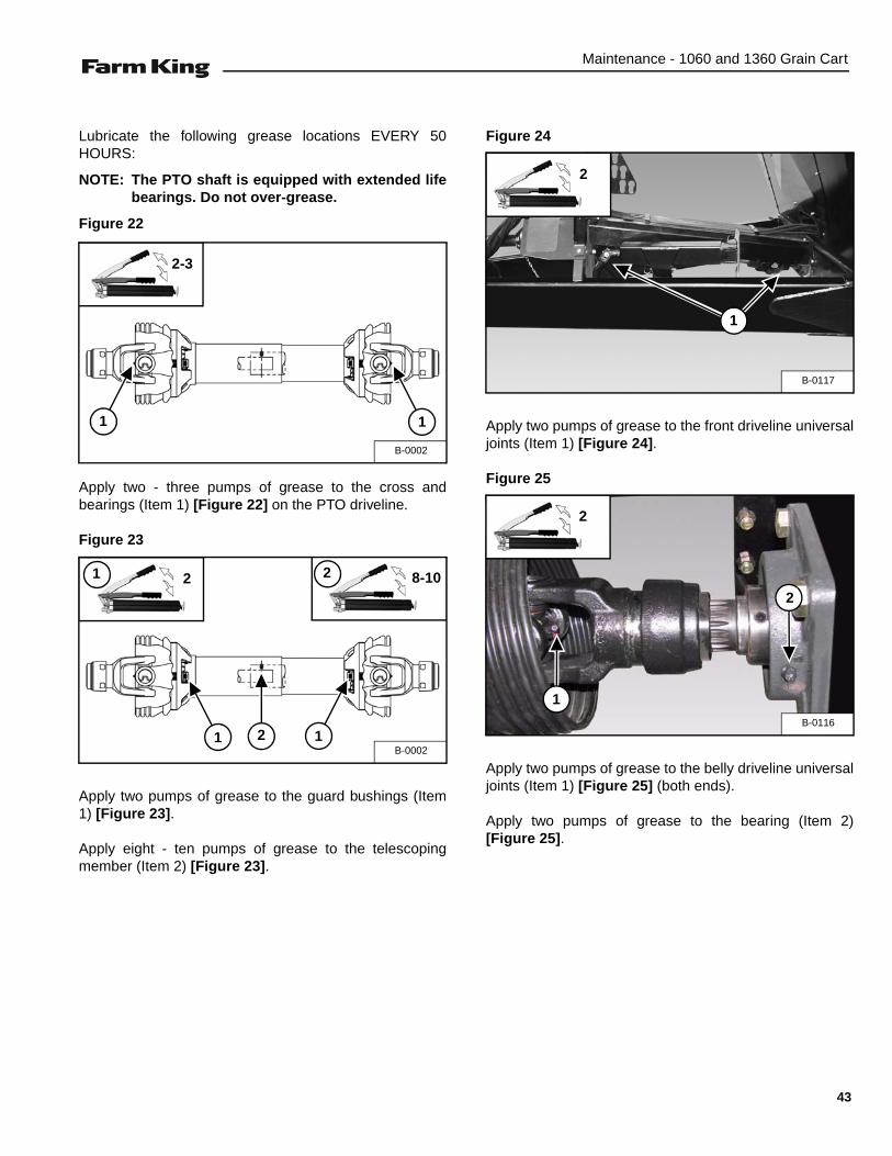
Lubricate the following grease locations EVERY 50HOURS:
NOTE: The PTO shaft is equipped with extended lifebearings. Do not over-grease.
Figure 22
Apply two - three pumps of grease to the cross andbearings (Item 1) [Figure 22] on the PTO driveline.
Figure 23
Apply two pumps of grease to the guard bushings (Item1) [Figure 23].
Apply eight - ten pumps of grease to the telescopingmember (Item 2) [Figure 23].
Figure 24
Apply two pumps of grease to the front driveline universaljoints (Item 1) [Figure 24].
Figure 25
Apply two pumps of grease to the belly driveline universaljoints (Item 1) [Figure 25] (both ends).
Apply two pumps of grease to the bearing (Item 2)[Figure 25].
B-0002
1 1
2-3
B-00021 12
21 8-102
B-0117
1
2
B-0116
1
2
2
43
Maintenance - 1060 and 1360 Grain Cart
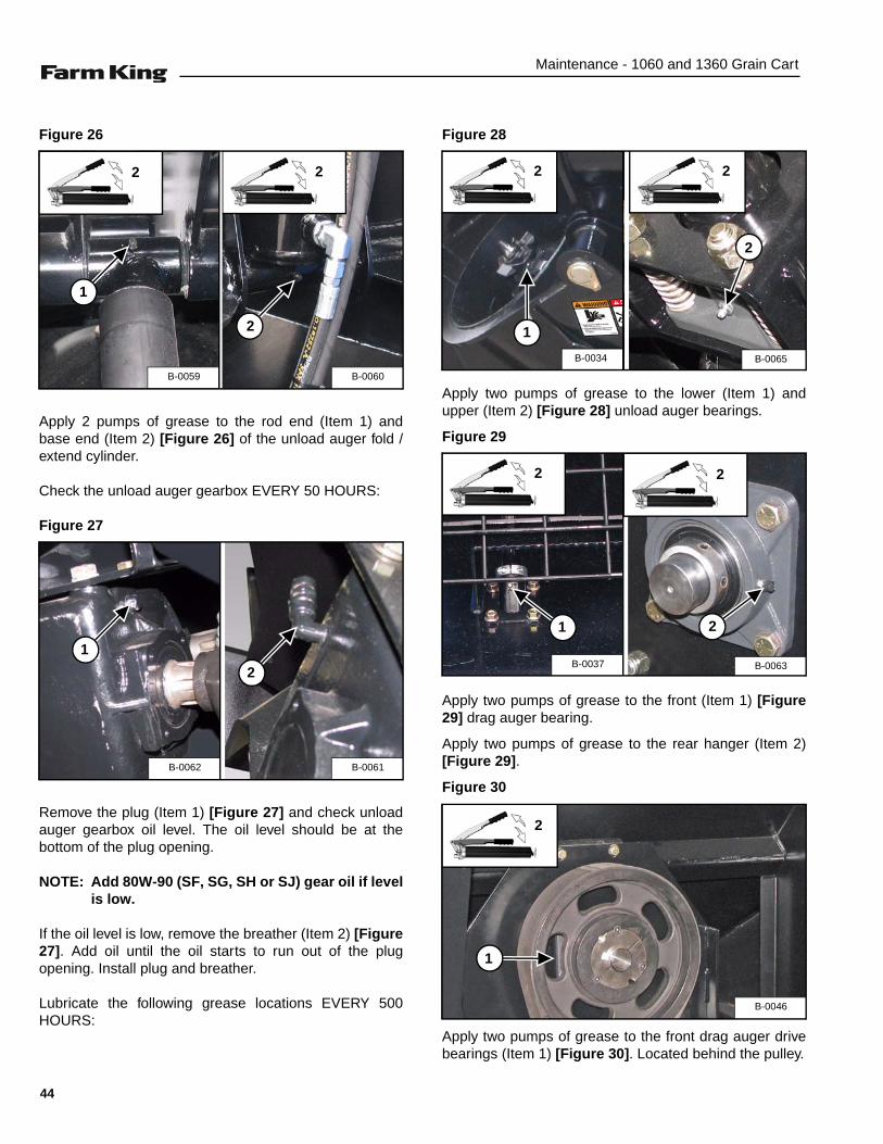
Figure 26
Apply 2 pumps of grease to the rod end (Item 1) andbase end (Item 2) [Figure 26] of the unload auger fold /extend cylinder.
Check the unload auger gearbox EVERY 50 HOURS:
Figure 27
Remove the plug (Item 1) [Figure 27] and check unloadauger gearbox oil level. The oil level should be at thebottom of the plug opening.
NOTE: Add 80W-90 (SF, SG, SH or SJ) gear oil if levelis low.
If the oil level is low, remove the breather (Item 2) [Figure27]. Add oil until the oil starts to run out of the plugopening. Install plug and breather.
Lubricate the following grease locations EVERY 500HOURS:
Figure 28
Apply two pumps of grease to the lower (Item 1) andupper (Item 2) [Figure 28] unload auger bearings.
Figure 29
Apply two pumps of grease to the front (Item 1) [Figure29] drag auger bearing.
Apply two pumps of grease to the rear hanger (Item 2)[Figure 29].
Figure 30
Apply two pumps of grease to the front drag auger drivebearings (Item 1) [Figure 30]. Located behind the pulley.
2
B-0060B-0059
1
2
2
B-0061
2
B-0062
1
2
B-0065B-0034
1
2
2
2
B-0063
2
B-0037
1
2
B-0046
1
2
44
Maintenance - 1060 and 1360 Grain Cart
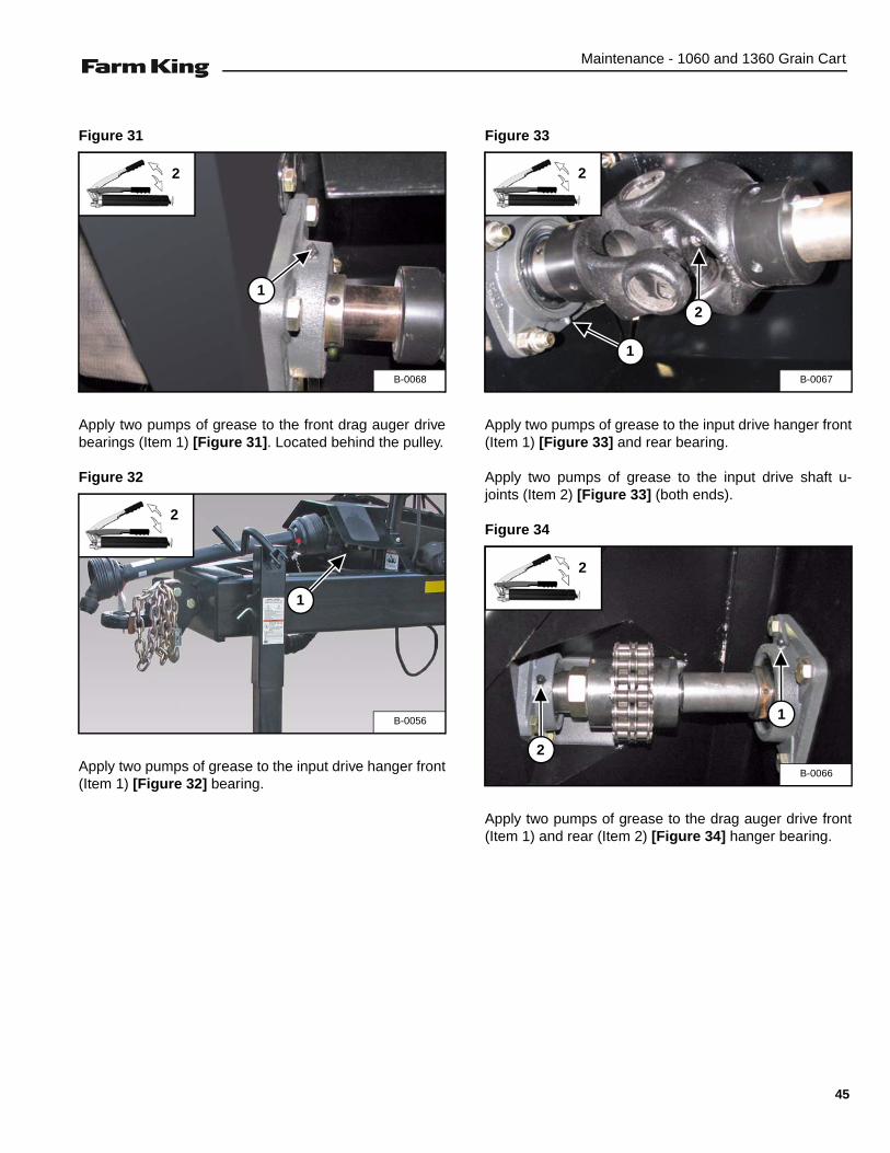
Figure 31
Apply two pumps of grease to the front drag auger drivebearings (Item 1) [Figure 31]. Located behind the pulley.
Figure 32
Apply two pumps of grease to the input drive hanger front(Item 1) [Figure 32] bearing.
Figure 33
Apply two pumps of grease to the input drive hanger front(Item 1) [Figure 33] and rear bearing.
Apply two pumps of grease to the input drive shaft u-joints (Item 2) [Figure 33] (both ends).
Figure 34
Apply two pumps of grease to the drag auger drive front(Item 1) and rear (Item 2) [Figure 34] hanger bearing.
B-0068
1
2
B-0056
1
2
B-0067
1
2
2
B-0066
1
2
2
45

Maintenance - 1060 and 1360 Grain Cart
DRAG AUGER BELT DRIVE
Adjusting Belt Tension
Figure 35
Push on the center of the long span to check the tensionof the belt. The belt should move approximately 9/32 in.(7 mm) when pushed on with 15 lb (6.8 kg) of force[Figure 35].
Figure 36
Lay a straight edge across the pulley faces to check thealignment [Figure 36]. Adjust alignment if pulley facesvary more than 1/32 inches (0.7 mm).
Figure 37
Loosen the two bolts (Item 1) [Figure 37] until thetensioner assembly is free from the frame.
Loosen jam nuts (Item 2), use the two bolts (Item 3)[Figure 37] to adjust tension.
Tighten the tensioner assembly against the drive beltuntil the belt deflection is approximately 9/32 in. (7 mm)when pushed on with 15 lb (6.8 kg) of force [Figure 35].
Retighten and torque jam nuts (Item 2) [Figure 37].
Retighten and torque bolts (Item 1) [Figure 37] securelyfastening the tensioner assembly to the frame.
AVOID INJURY OR DEATHBefore you leave the operator’s position:• Always park on a flat level surface.• Place all controls in NEUTRAL.• Engage the park brake.• Stop the engine and remove the key.• Wait for all moving parts to stop.
B-0069
9/32 in. (7 mm)
B-0070
1/32 in. (0.7 mm)
B-0045
1
3
2
46

Maintenance - 1060 and 1360 Grain Cart
PTO DRIVELINE
Removal
Figure 38
Loosen the bolt and lock nut (Item 1) [Figure 38] onclutch end of the main PTO driveline and removedriveline from the 1.75” front PTO shaft.
Disassembly And Assembly
Figure 39
Separate the two sections of the driveline [Figure 39].
Assembly: Slide the two sections together. Check thedriveline telescopes freely.
Figure 40
Release guard bearing lock tabs (two tabs per shield) onthe two guards [Figure 40].
Assembly: Insert the tabs through the holes and seat inposition. Push each tab down to secure guard to eachshaft section.
Figure 41
Remove the guard(s) from the shaft(s) [Figure 41].
Assembly: Insert the shaft into its respective guard andalign the tabs with the holes.
Cleaning And Inspection
NOTE: Inspect the driveline components, replace alldamaged or worn components.
Use solvent to clean the shaft (Item 1) and tube (Item 2)[Figure 41]. Use compressed air to dry and removeexcess solvent from the parts.
Apply a light coat of grease to the shaft and the tube end.
Use solvent to clean the slide collars, yokes, crosses andbearings. Use compressed air to dry the parts.
Apply a light coat of grease to the inside of the slidecollars.
B-0071
1
B-0106
B-0107
B-0108
1
2
47

Maintenance - 1060 and 1360 Grain Cart
TANDEM AXLE
Wheel Lug Nut Torque
Check the torque on wheel lug nuts daily. Tighten lugnuts to 420 ft-lb torque.
Inner Tire Access
Empty the gain cart.
Park the tractor / equipment on a flat level surface.
Place all controls in neutral, engage the park brake, stopthe engine and wait for all moving parts to stop. Leavethe operator’s position.
Figure 42
Place chock blocks (Item 1) [Figure 42] behind and infront the tractor tire.
Figure 43
Place a jack (5-Ton minimum) (Item 1) [Figure 43] underthe frame. Raise the jack until both wheels are slightly offthe ground.
NOTE: Place blocks under the frame to help securethe grain cart when wheels are raised off theground.
Loosen and remove the six bolts (Item 2) [Figure 43] atthe rear of the swing axle.
Move / pivot the swing axle out / away from the grain cart.
Check and re-torque inner wheel lug nuts to 420 ft-lbtorque.
Move / pivot the swing axle back into the operatingposition.
Install the six bolts and tighten to 300 ft-lb torque.
AVOID INJURY OR DEATH
Before you leave the operator’s position:
• Always park on a flat level surface.• Place all controls in NEUTRAL.• Engage the park brake.• Stop the engine and remove the key.• Wait for all moving parts to stop.
AVOID INJURY OR DEATH• The parking brake must be engaged before
leaving the operator’s position. Rollaway canoccur because the transmission may notprevent machine movement.
• Always chock tires before performing anymaintenance or service.
B-0004
1
B-0072
1 2
48
Maintenance - 1060 and 1360 Grain Cart
SINGLE AXLE
Wheel Lug Nut Torque
Check the torque on wheel lug nuts daily. Tighten lugnuts to 420 ft-lb torque.
SAFETY SIGN (DECAL) INSTALLATION
Procedure
• Remove all portions of the damaged safety sign(decal).
• Thoroughly clean the area with glass cleaner.Removing all adhesive residue.
• Allow the area to dry completely before installing thenew safety sign (decal).
• Position the safety sign (decal) in the correct location.Remove a small portion of the backing paper on thesafety sign (decal).
• Press on the safety sign (decal) where the backingpaper has been removed.
• Slowly remove the remaining backing paper, pressingon the safety sign (decal) as the backing paper isremoved.
• Using the backing paper, pressing firmly, move thebacking paper over the entire safety sign (decal) area.
NOTE: Small air pockets can be pierced with a pinand smoothed out using the piece of thebacking paper.
STORAGE AND RETURN TO SERVICE
Storage
Sometimes it may be necessary to store your Farm Kinggrain cart for an extended period of time. Below is a list ofitems to perform before storage.
• Thoroughly clean the equipment.
• Completely drain water from hopper.
• Lubricate the equipment.
• Place hydraulic hoses and 7-pin connector in thestorage brackets.
• Inspect the hitch and all welds on the equipment forwear and damage.
• Check for loose hardware, missing guards, ordamaged parts.
• Check for damaged or missing safety signs (decals).Replace if necessary.
• Replace worn or damaged parts.
• Touch up all paint nicks and scratches to preventrusting.
• Close the roll-top cover (if equipped).
• Place the equipment in a dry protected shelter.
NOTE: If a dry protected shelter is not available,cover with a waterproof tarp and tie downsecurely.
• Place the equipment flat on the ground.
• Support the jack / frame with planks if required.
Return To Service
After the Farm King grain cart has been in storage, it isnecessary to follow a list of items to return the equipmentto service.
• Be sure all shields and guards are in place.
• Lubricate the equipment.
• Connect to a tractor and operate equipment, verify allfunctions operate correctly.
• Check for leaks. Repair as needed.
When replacing safety signs (decals), thetemperature must be above 10° C (50° F).
DO NOT permit children to play on or around thestored machine.
49

Maintenance - 1060 and 1360 Grain Cart
50
Parts Identification - 1060 and 1360 Grain Cart
PARTS IDENTIFICATION
GENERAL INFORMATION . . . . . . . . . . . . . . . . . . . . . . . . . . . . . . . . . . . . . . . . . . . . . . . . . . . . . . . 53
DRIVE GROUP (1060 & 1360 MODELS) . . . . . . . . . . . . . . . . . . . . . . . . . . . . . . . . . . . . . . . . . . . . 53Components . . . . . . . . . . . . . . . . . . . . . . . . . . . . . . . . . . . . . . . . . . . . . . . . . . . . . . . . . . . . . . . . 53Belt Drive Assembly . . . . . . . . . . . . . . . . . . . . . . . . . . . . . . . . . . . . . . . . . . . . . . . . . . . . . . . . . . 54U-joint (55R 1.75 x 1.75) . . . . . . . . . . . . . . . . . . . . . . . . . . . . . . . . . . . . . . . . . . . . . . . . . . . . . . . 55U-joint (55R 1.75 x 2.00) . . . . . . . . . . . . . . . . . . . . . . . . . . . . . . . . . . . . . . . . . . . . . . . . . . . . . . . 55PTO Shaft (Drag Auger) . . . . . . . . . . . . . . . . . . . . . . . . . . . . . . . . . . . . . . . . . . . . . . . . . . . . . . . 56PTO Shaft (Auto Clutch) . . . . . . . . . . . . . . . . . . . . . . . . . . . . . . . . . . . . . . . . . . . . . . . . . . . . . . . 57
AXLE & HITCH OPTIONS (1060 & 1360 MODELS) . . . . . . . . . . . . . . . . . . . . . . . . . . . . . . . . . . . . 58Single Axle Components . . . . . . . . . . . . . . . . . . . . . . . . . . . . . . . . . . . . . . . . . . . . . . . . . . . . . . . 58Single Axle Weldment . . . . . . . . . . . . . . . . . . . . . . . . . . . . . . . . . . . . . . . . . . . . . . . . . . . . . . . . . 58Single Axle Assembly (Scale) . . . . . . . . . . . . . . . . . . . . . . . . . . . . . . . . . . . . . . . . . . . . . . . . . . . 59Hub Assembly . . . . . . . . . . . . . . . . . . . . . . . . . . . . . . . . . . . . . . . . . . . . . . . . . . . . . . . . . . . . . . . 60Walking Tandem Axle Assembly . . . . . . . . . . . . . . . . . . . . . . . . . . . . . . . . . . . . . . . . . . . . . . . . . 61LH Tandem Rocker Assembly . . . . . . . . . . . . . . . . . . . . . . . . . . . . . . . . . . . . . . . . . . . . . . . . . . . 62RH Tandem Rocker Assembly . . . . . . . . . . . . . . . . . . . . . . . . . . . . . . . . . . . . . . . . . . . . . . . . . . 63Walking Tandem Axle Assembly (Scale) . . . . . . . . . . . . . . . . . . . . . . . . . . . . . . . . . . . . . . . . . . . 64LH Tandem Rocker Assembly (Scale) . . . . . . . . . . . . . . . . . . . . . . . . . . . . . . . . . . . . . . . . . . . . 66RH Tandem Rocker Assembly (Scale) . . . . . . . . . . . . . . . . . . . . . . . . . . . . . . . . . . . . . . . . . . . . 67Hub Assembly (10-Bolt, 13.19 BC) . . . . . . . . . . . . . . . . . . . . . . . . . . . . . . . . . . . . . . . . . . . . . . . 68Hub & Spindle Assembly (25K) . . . . . . . . . . . . . . . . . . . . . . . . . . . . . . . . . . . . . . . . . . . . . . . . . . 69
DRAG AUGER ASSEMBLY . . . . . . . . . . . . . . . . . . . . . . . . . . . . . . . . . . . . . . . . . . . . . . . . . . . . . . . 70Components . . . . . . . . . . . . . . . . . . . . . . . . . . . . . . . . . . . . . . . . . . . . . . . . . . . . . . . . . . . . . . . . 70
DRAG AUGER GATE ASSEMBLY (1060 & 1360 MODELS) . . . . . . . . . . . . . . . . . . . . . . . . . . . . . . 72Components . . . . . . . . . . . . . . . . . . . . . . . . . . . . . . . . . . . . . . . . . . . . . . . . . . . . . . . . . . . . . . . . 72
HITCH AND JACK ASSEMBLY . . . . . . . . . . . . . . . . . . . . . . . . . . . . . . . . . . . . . . . . . . . . . . . . . . . . 75Components . . . . . . . . . . . . . . . . . . . . . . . . . . . . . . . . . . . . . . . . . . . . . . . . . . . . . . . . . . . . . . . . 75
UPPER FRAME ASSEMBLY (1060 & 1360 MODELS) . . . . . . . . . . . . . . . . . . . . . . . . . . . . . . . . . . 76Upper Frame Components . . . . . . . . . . . . . . . . . . . . . . . . . . . . . . . . . . . . . . . . . . . . . . . . . . . . . 76
LADDER GROUP (1060 & 1360 MODELS) . . . . . . . . . . . . . . . . . . . . . . . . . . . . . . . . . . . . . . . . . . . 77Ladder Assembly . . . . . . . . . . . . . . . . . . . . . . . . . . . . . . . . . . . . . . . . . . . . . . . . . . . . . . . . . . . .77
UPPER AUGER ASSEMBLY (1060 & 1360 MODELS) . . . . . . . . . . . . . . . . . . . . . . . . . . . . . . . . . . 78Upper Auger Components . . . . . . . . . . . . . . . . . . . . . . . . . . . . . . . . . . . . . . . . . . . . . . . . . . . . . 78
BIN EXTENSIONS (1360 MODELS) . . . . . . . . . . . . . . . . . . . . . . . . . . . . . . . . . . . . . . . . . . . . . . . . 80Components . . . . . . . . . . . . . . . . . . . . . . . . . . . . . . . . . . . . . . . . . . . . . . . . . . . . . . . . . . . . . . . . 80
51
Parts Identification - 1060 and 1360 Grain Cart
BIN SUPPORT BRACES (1060 & 1360 MODELS) . . . . . . . . . . . . . . . . . . . . . . . . . . . . . . . . . . . . .81Components . . . . . . . . . . . . . . . . . . . . . . . . . . . . . . . . . . . . . . . . . . . . . . . . . . . . . . . . . . . . . . . .81
MAIN BIN PANEL ASSEMBLY . . . . . . . . . . . . . . . . . . . . . . . . . . . . . . . . . . . . . . . . . . . . . . . . . . . . .82Blue Grain Cart . . . . . . . . . . . . . . . . . . . . . . . . . . . . . . . . . . . . . . . . . . . . . . . . . . . . . . . . . . . . .82Green Grain Cart . . . . . . . . . . . . . . . . . . . . . . . . . . . . . . . . . . . . . . . . . . . . . . . . . . . . . . . . . . . .84Red Grain Cart . . . . . . . . . . . . . . . . . . . . . . . . . . . . . . . . . . . . . . . . . . . . . . . . . . . . . . . . . . . . . .86Yellow Grain Cart . . . . . . . . . . . . . . . . . . . . . . . . . . . . . . . . . . . . . . . . . . . . . . . . . . . . . . . . . . . .88
LIGHTING & MARKING . . . . . . . . . . . . . . . . . . . . . . . . . . . . . . . . . . . . . . . . . . . . . . . . . . . . . . . . . .90Components . . . . . . . . . . . . . . . . . . . . . . . . . . . . . . . . . . . . . . . . . . . . . . . . . . . . . . . . . . . . . . . .90
SLIDE GATE ASSEMBLY . . . . . . . . . . . . . . . . . . . . . . . . . . . . . . . . . . . . . . . . . . . . . . . . . . . . . . . . .91Components . . . . . . . . . . . . . . . . . . . . . . . . . . . . . . . . . . . . . . . . . . . . . . . . . . . . . . . . . . . . . . . .91
LOWER FRAME ASSEMBLY . . . . . . . . . . . . . . . . . . . . . . . . . . . . . . . . . . . . . . . . . . . . . . . . . . . . . .92Front Components . . . . . . . . . . . . . . . . . . . . . . . . . . . . . . . . . . . . . . . . . . . . . . . . . . . . . . . . . . .92PTO Hanger Mounting Components . . . . . . . . . . . . . . . . . . . . . . . . . . . . . . . . . . . . . . . . . . . . .94
BIN FLOOR GRATING ASSEMBLY (1060 & 1360 MODELS) . . . . . . . . . . . . . . . . . . . . . . . . . . . . .95Components . . . . . . . . . . . . . . . . . . . . . . . . . . . . . . . . . . . . . . . . . . . . . . . . . . . . . . . . . . . . . . . .95
CAMERA KIT (OPTIONAL) (1060 & 1360 MODELS) . . . . . . . . . . . . . . . . . . . . . . . . . . . . . . . . . . .96Components . . . . . . . . . . . . . . . . . . . . . . . . . . . . . . . . . . . . . . . . . . . . . . . . . . . . . . . . . . . . . . . .96
TARP ASSEMBLY (1060 & 1360 MODELS) . . . . . . . . . . . . . . . . . . . . . . . . . . . . . . . . . . . . . . . . . .971060 Components . . . . . . . . . . . . . . . . . . . . . . . . . . . . . . . . . . . . . . . . . . . . . . . . . . . . . . . . . . .971360 Components . . . . . . . . . . . . . . . . . . . . . . . . . . . . . . . . . . . . . . . . . . . . . . . . . . . . . . . . . . .98
52
Parts - 1060 and 1360 Grain Cart
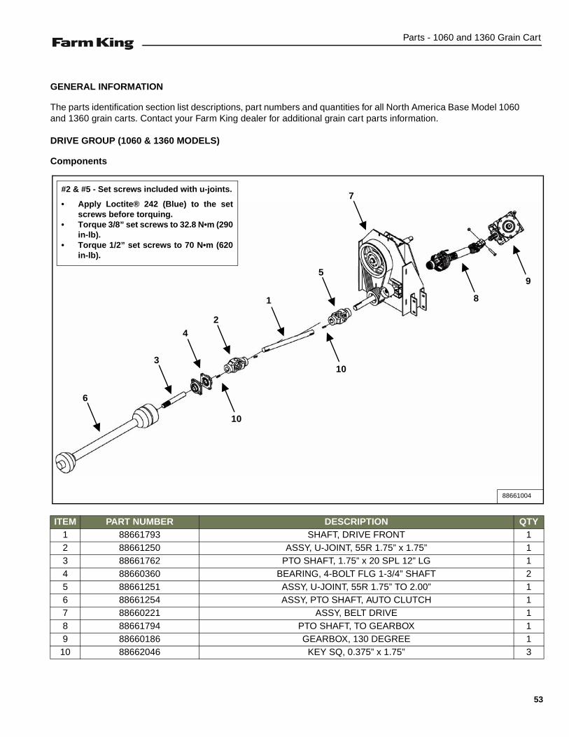
GENERAL INFORMATION
The parts identification section list descriptions, part numbers and quantities for all North America Base Model 1060and 1360 grain carts. Contact your Farm King dealer for additional grain cart parts information.
DRIVE GROUP (1060 & 1360 MODELS)
Components
ITEM PART NUMBER DESCRIPTION QTY1 88661793 SHAFT, DRIVE FRONT 12 88661250 ASSY, U-JOINT, 55R 1.75” x 1.75” 13 88661762 PTO SHAFT, 1.75” x 20 SPL 12” LG 14 88660360 BEARING, 4-BOLT FLG 1-3/4” SHAFT 25 88661251 ASSY, U-JOINT, 55R 1.75” TO 2.00” 16 88661254 ASSY, PTO SHAFT, AUTO CLUTCH 17 88660221 ASSY, BELT DRIVE 18 88661794 PTO SHAFT, TO GEARBOX 19 88660186 GEARBOX, 130 DEGREE 1
10 88662046 KEY SQ, 0.375” x 1.75” 3
88661004
3
4
6
2
1
10
10
5
7
9
8
#2 & #5 - Set screws included with u-joints.
• Apply Loctite® 242 (Blue) to the setscrews before torquing.
• Torque 3/8” set screws to 32.8 N•m (290in-lb).
• Torque 1/2” set screws to 70 N•m (620in-lb).
53
Parts - 1060 and 1360 Grain Cart
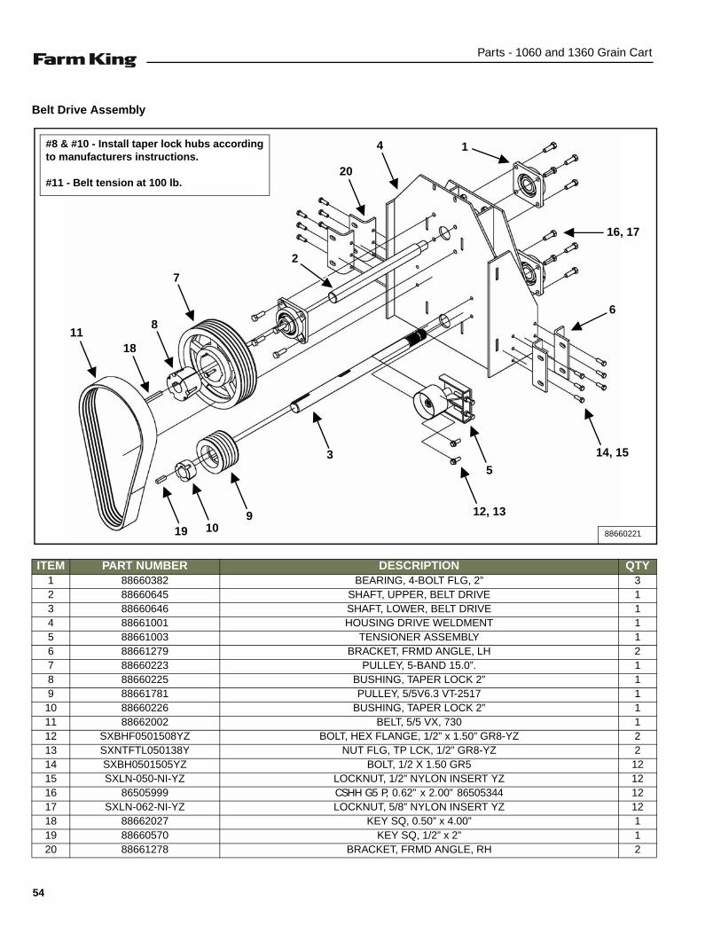
Belt Drive Assembly
ITEM PART NUMBER DESCRIPTION QTY1 88660382 BEARING, 4-BOLT FLG, 2” 32 88660645 SHAFT, UPPER, BELT DRIVE 13 88660646 SHAFT, LOWER, BELT DRIVE 14 88661001 HOUSING DRIVE WELDMENT 15 88661003 TENSIONER ASSEMBLY 16 88661279 BRACKET, FRMD ANGLE, LH 27 88660223 PULLEY, 5-BAND 15.0”. 18 88660225 BUSHING, TAPER LOCK 2” 19 88661781 PULLEY, 5/5V6.3 VT-2517 110 88660226 BUSHING, TAPER LOCK 2” 111 88662002 BELT, 5/5 VX, 730 112 SXBHF0501508YZ BOLT, HEX FLANGE, 1/2” x 1.50” GR8-YZ 213 SXNTFTL050138Y NUT FLG, TP LCK, 1/2” GR8-YZ 214 SXBH0501505YZ BOLT, 1/2 X 1.50 GR5 1215 SXLN-050-NI-YZ LOCKNUT, 1/2” NYLON INSERT YZ 1216 86505999 CSHH G5 P, 0.62” x 2.00” 86505344 1217 SXLN-062-NI-YZ LOCKNUT, 5/8” NYLON INSERT YZ 1218 88662027 KEY SQ, 0.50” x 4.00” 119 88660570 KEY SQ, 1/2” x 2” 120 88661278 BRACKET, FRMD ANGLE, RH 2
88660221
1118
8
7
19 109
3
12, 13
5
14, 15
16, 17
14
20
2
6
#8 & #10 - Install taper lock hubs accordingto manufacturers instructions.
#11 - Belt tension at 100 lb.
54
Parts - 1060 and 1360 Grain Cart
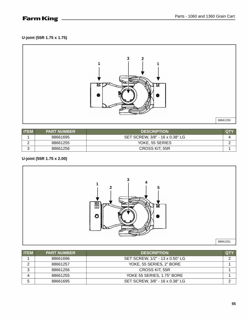
U-joint (55R 1.75 x 1.75)
U-joint (55R 1.75 x 2.00)
ITEM PART NUMBER DESCRIPTION QTY1 88661695 SET SCREW, 3/8” - 16 x 0.38” LG 42 88661255 YOKE, 55 SERIES 23 88661256 CROSS KIT, 55R 1
ITEM PART NUMBER DESCRIPTION QTY1 88661696 SET SCREW, 1/2” - 13 x 0.50” LG 22 88661257 YOKE, 55 SERIES, 2” BORE 13 88661256 CROSS KIT, 55R 14 88661255 YOKE 55 SERIES, 1.75” BORE 15 88661695 SET SCREW, 3/8” - 16 x 0.38” LG 2
88661250
311
2
88661251
3
51
24
55

Parts - 1060 and 1360 Grain Cart
PTO Shaft (Drag Auger)
ITEM PART NUMBER DESCRIPTION QTY1 88662043 LOCKNUT, 5/8” - 11 12 88662044 BOLT, 5/8” - 11 x 3.50” LG. GR8 13 88662039 YOKE 14 88661268 35E CROSS KIT 25 88662042 YOKE & SHAFT, 1.31” - 20 SPLINE 16 88661272 SAFETY SIGN 17 88661274 SAFETY SIGN 18 88661271 GUARD REPAIR KIT 19 88662040 INNER GUARD 1
10 88662041 YOKE, TUBE & SLIP SLEEVE 111 88661267 SAFETY SLIDE LOCK YOKE ASSEMBLY 112 88661266 SSL / AUTO-LOK REPAIR KIT 1
88661794
14
2 5
7
6
1011
123 4
8
9
56

Parts - 1060 and 1360 Grain Cart
PTO Shaft (Auto Clutch)
ITEM PART NUMBER DESCRIPTION QTY1 88661266 KIT, SSL / AUTO-LOK REPAIR 12 88661267 YOKE, SAFETY SLIDE LOCK ASSEMBLY 13 88661268 CROSS KIT, 35E 24 88661269 YOKE & SHAFT ASSEMBLY 15 88661270 GUARD, OUTER 16 88661271 GUARD REPAIR KIT 17 88661272 SAFETY SIGN 18 88661273 DECAL, WARNING 19 88661274 SAFETY SIGN 1
10 88661275 GUARD, INNER 111 88661276 YOKE, TUBE & SLIP SLEEVE ASSEMBLY 112 88661277 CLUTCH, AUTO OVERRUNNING 113 88661676 BOLT, M18 x 2 x 80 LG., CL 10.9 214 88661677 LOCK NUT, M16 x 2 2
88661254
1 8 9
3 4
25
7610
6
11 3 12
13 14
57

Parts - 1060 and 1360 Grain Cart
AXLE & HITCH OPTIONS (1060 & 1360 MODELS)
Single Axle Components
Single Axle Weldment
ITEM PART NUMBER DESCRIPTION QTY1 88661339 SINGLE AXLE WELDMENT 12 88661222 HUB, SPINDLE ASSEMBLY 35K 23 88660403 DRAWBAR, HITCH 1
ITEM PART NUMBER DESCRIPTION QTY1 88661180 SINGLE AXLE WELDMENT 12 00281074 BOLT, HEX 0.75” x 2.50” GR8 Pl 163 SXLN-075-NI-YZ LOCKNUT, 3/4” NYLON INSERT YZ 164 88660497 LOCKNUT, NY INSERT 1.00” NF Gr8 PL 25 SXBH-100-850-8 CSHH G8P 1.0” x 8.50” 86505346 2
88664509
3
1
2
88661339A
5
1
2
4
32
3
58
Parts - 1060 and 1360 Grain Cart
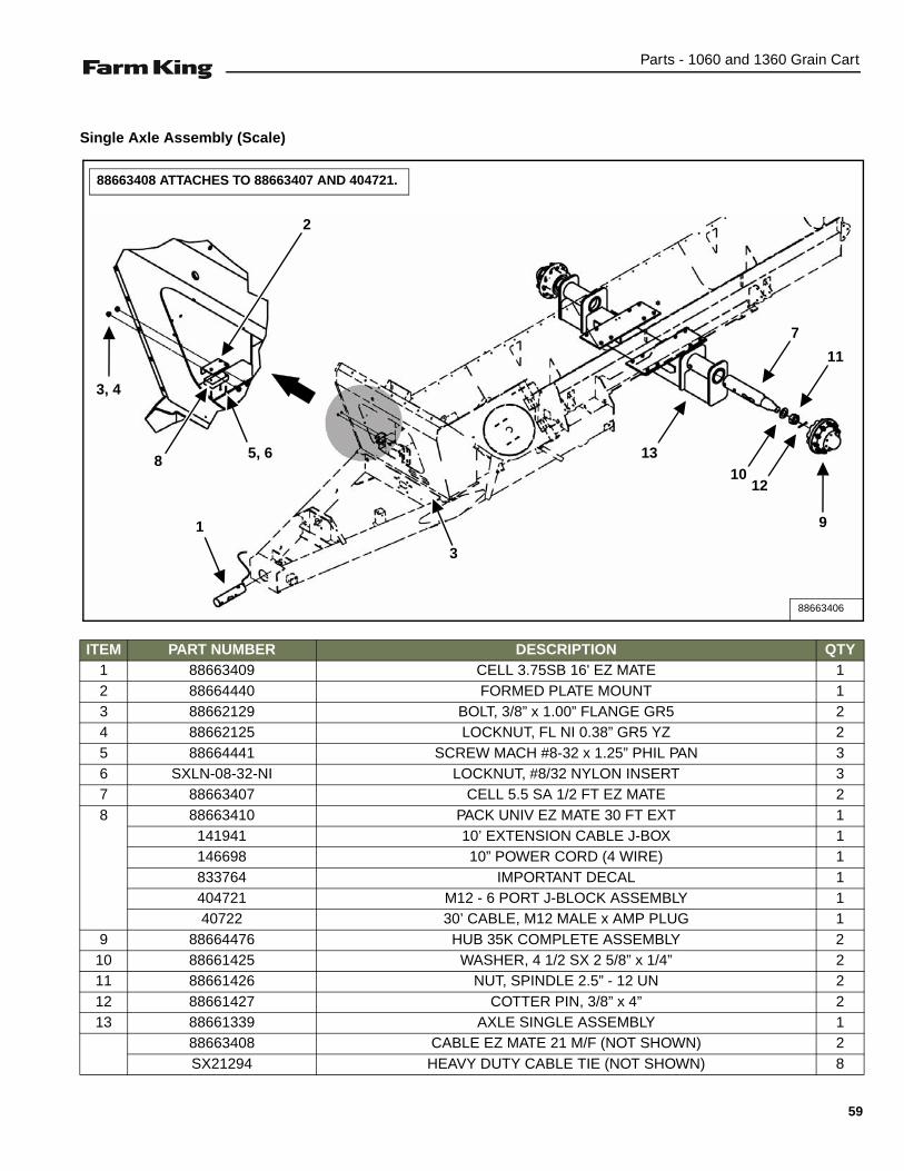
Single Axle Assembly (Scale)
ITEM PART NUMBER DESCRIPTION QTY1 88663409 CELL 3.75SB 16' EZ MATE 12 88664440 FORMED PLATE MOUNT 13 88662129 BOLT, 3/8” x 1.00” FLANGE GR5 24 88662125 LOCKNUT, FL NI 0.38” GR5 YZ 25 88664441 SCREW MACH #8-32 x 1.25” PHIL PAN 36 SXLN-08-32-NI LOCKNUT, #8/32 NYLON INSERT 37 88663407 CELL 5.5 SA 1/2 FT EZ MATE 28 88663410 PACK UNIV EZ MATE 30 FT EXT 1
141941 10’ EXTENSION CABLE J-BOX 1146698 10” POWER CORD (4 WIRE) 1833764 IMPORTANT DECAL 1404721 M12 - 6 PORT J-BLOCK ASSEMBLY 140722 30’ CABLE, M12 MALE x AMP PLUG 1
9 88664476 HUB 35K COMPLETE ASSEMBLY 210 88661425 WASHER, 4 1/2 SX 2 5/8” x 1/4” 211 88661426 NUT, SPINDLE 2.5” - 12 UN 212 88661427 COTTER PIN, 3/8” x 4” 213 88661339 AXLE SINGLE ASSEMBLY 1
88663408 CABLE EZ MATE 21 M/F (NOT SHOWN) 2SX21294 HEAVY DUTY CABLE TIE (NOT SHOWN) 8
88663406
3
5, 6
1
2
1013
3, 4
12
8
9
11
88663408 ATTACHES TO 88663407 AND 404721.
7
59

Parts - 1060 and 1360 Grain Cart
Hub Assembly
ITEM PART NUMBER DESCRIPTION QTY1 88661415 HUB, SUB ASSEMBLY 1
88661416 HUB MACHINING 188661417 BEARING CUP71750, TIMKEN 188661418 BEARING CUP 653, TIMKEN 188661419 STUD BOLT, M33 x 1.5 x 4” 10.91 BP 1088661420 GREASE FITTING, 1/8” - 27 TAPER 1
2 88661421 BEARING CONE 71455, TIMKEN 13 88661422 BEARING CONE 663, TIMKEN 14 88661423 SEAL, GREASE, PEER (POS5507556SA) 15 88661428 HUB CAP OIL PAPER GASKET 16 88661429 BOLT ON 35K/50K HUB CAP, ZP 17 88661430 BOLT HEX 5/16” x 1/2”, GR5, ZP 88 88661431 FLANGE NUT, M22 x 1.5”, 2 PIECE 10
88664476
3
5
4
8
21
7
6
60

Parts - 1060 and 1360 Grain Cart
Walking Tandem Axle Assembly
ITEM PART NUMBER DESCRIPTION QTY
1 88660481 PIN, AXLE WELDMENT 2
2 88660054 AXLE PIVOT WELDMENT 2
3 88660077 FRONT AXLE WELDMENT 1
4 88660083 REAR AXLE WELDMENT 1
5 88660492 LOCKNUT, 3/4” NI GR5 YZ 44
6 88660058 LH SWING AXLE, MACHINED 1
7 88660517 RH SWING AXLE, MACHINED 1
8 88664519 LH TANDEM ROCKER ASSEMBLY 1
9 88664518 RH TANDEM ROCKER ASSEMBLY 1
10 09635076 CSHH 3/4” x 2” GR8 Plt 86505346 44
11 88664416 LOCKNUT, 1 3/4” - 12 GR5 NI PLAIN 2
12 SXG1610 GREASE ZERK, 1/8” N STR. 2
13 88660403 DRAWBAR, HITCH 1
88664517
12
9
10
5
5
10
13
106
2
11
1
310, 5
4
8
NOTE:
Apply anti-seize to pin (1) 88660481 before installing.
FRONT
7
61
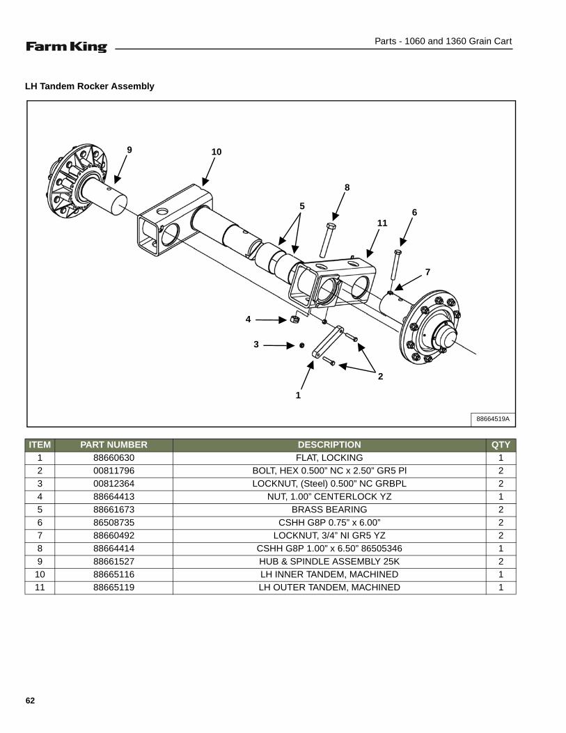
Parts - 1060 and 1360 Grain Cart
LH Tandem Rocker Assembly
ITEM PART NUMBER DESCRIPTION QTY1 88660630 FLAT, LOCKING 12 00811796 BOLT, HEX 0.500” NC x 2.50” GR5 Pl 23 00812364 LOCKNUT, (Steel) 0.500” NC GRBPL 24 88664413 NUT, 1.00” CENTERLOCK YZ 15 88661673 BRASS BEARING 26 86508735 CSHH G8P 0.75” x 6.00” 27 88660492 LOCKNUT, 3/4” NI GR5 YZ 28 88664414 CSHH G8P 1.00” x 6.50” 86505346 19 88661527 HUB & SPINDLE ASSEMBLY 25K 2
10 88665116 LH INNER TANDEM, MACHINED 111 88665119 LH OUTER TANDEM, MACHINED 1
88664519A
9
5
8
6
7
2
1
3
4
10
11
62
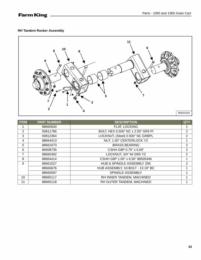
Parts - 1060 and 1360 Grain Cart
RH Tandem Rocker Assembly
ITEM PART NUMBER DESCRIPTION QTY1 88660630 FLAT, LOCKING 12 00811796 BOLT, HEX 0.500” NC x 2.50” GR5 Pl 23 00812364 LOCKNUT, (Steel) 0.500” NC GRBPL 24 88664413 NUT, 1.00” CENTERLOCK YZ 15 88661673 BRASS BEARING 26 86508735 CSHH G8P 0.75” x 6.00” 27 88660492 LOCKNUT, 3/4” NI GR5 YZ 28 88664414 CSHH G8P 1.00” x 6.50” 86505346 19 88661527 HUB & SPINDLE ASSEMBLY 25K 2
88660676 HUB ASSEMBLY, 10-BOLT - 13.19” BC 188665597 SPINDLE ASSEMBLY 1
10 88665117 RH INNER TANDEM, MACHINED 111 88665118 RH OUTER TANDEM, MACHINED 1
88664518A
9
5
86
7
6
7
21
4
3
10
11
63

Parts - 1060 and 1360 Grain Cart
AXLE & HITCH OPTIONS (1060 & 1360 MODELS) (CONT’D)
Walking Tandem Axle Assembly (Scale)
88664461
7
12
14, 15, 1619
21
25
22
24
20
23
9
10
5
5
10
13
10, 5
62
11
1
3
18
17
10, 5
4
8
WIRING NOTE:
88664562 LEAD ATTACHES TO 404721
FRONT
64

Parts - 1060 and 1360 Grain Cart
ITEM PART NUMBER DESCRIPTION QTY
1 88660481 PIN, AXLE WELDMENT 2
2 88660054 AXLE PIVOT WELDMENT 2
3 88660077 FRONT AXLE WELDMENT 1
4 88660083 REAR AXLE WELDMENT 1
5 88660492 LOCKNUT, 3/4” NI GR5 YZ 44
6 88660058 LH SWING AXLE, MACHINED 1
7 88660517 RH SWING AXLE, MACHINED 1
8 88664533 LH TANDEM ROCKER ASSEMBLY 1
9 88664534 RH TANDEM ROCKER ASSEMBLY 1
10 09635076 CSHH 3/4” x 2” GR8 Plt 86505346 44
11 88664416 LOCKNUT, 1 3/4” - 12 GR5 NI PLAIN 2
12 SXG1610 GREASE ZERK, 1/8” N STR. 2
13 88664442 GUARD WIRING SCALES 2
14 SXFW-038 YZ FLAT WASHER, 5/16” YZ 6
15 81593 LOCK WASHER, 0.375” PL 2
16 00012012 CSHH G5 P 0.38” x 0.75” 6
17 SX0708796 CLIP, INSULATED 1” CLOSED 4
18 SXLN-038-NIYZ LOCKNUT, 3/8” NYLON INSERT NC. YZ 2
19 88663409 CELL 3.75” SB 16’ EZ MATE 1
20 88664440 PLATE, MOUNT FORMED 1
21 88662129 BOLT, 3/8” x 1.00” FLANGE GR5 2
22 88662125 LOCKNUT, 0.38” GR5 FL NI YZ 2
23 88663410 PACK UNIV EZ MATE 30 FT EXT 1
141941 CABLE J-BOX EXT 10’ 1
146698 POWER CORD 10’ 4 WIRE 1
833764 DECAL IMPORTANT 1
404721 M12 J-BLOCK 6 PORT ASSEMBLY 1
404722 CABLE 30’ M12 MALE x AMP PLUG 1
24 88664441 MACHINE SCREW #8-32 x 1.25” PHIL PAN 3
25 SXLN-08-32-NI LOCKNUT, #8/32 NYLON INSERT 3
65
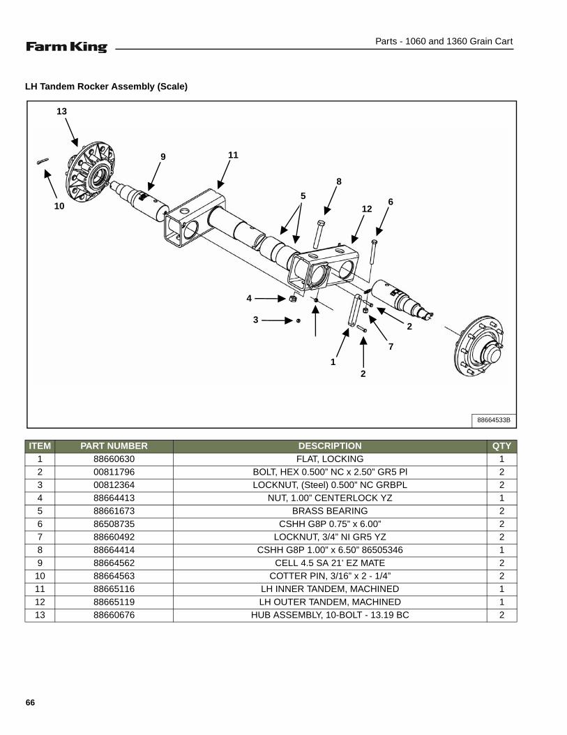
Parts - 1060 and 1360 Grain Cart
LH Tandem Rocker Assembly (Scale)
ITEM PART NUMBER DESCRIPTION QTY1 88660630 FLAT, LOCKING 12 00811796 BOLT, HEX 0.500” NC x 2.50” GR5 Pl 23 00812364 LOCKNUT, (Steel) 0.500” NC GRBPL 24 88664413 NUT, 1.00” CENTERLOCK YZ 15 88661673 BRASS BEARING 26 86508735 CSHH G8P 0.75” x 6.00” 27 88660492 LOCKNUT, 3/4” NI GR5 YZ 28 88664414 CSHH G8P 1.00” x 6.50” 86505346 19 88664562 CELL 4.5 SA 21’ EZ MATE 2
10 88664563 COTTER PIN, 3/16” x 2 - 1/4” 211 88665116 LH INNER TANDEM, MACHINED 112 88665119 LH OUTER TANDEM, MACHINED 113 88660676 HUB ASSEMBLY, 10-BOLT - 13.19 BC 2
88664533B
9
13
10
11
5
8
126
7
2
21
3
4
66

Parts - 1060 and 1360 Grain Cart
RH Tandem Rocker Assembly (Scale)
ITEM PART NUMBER DESCRIPTION QTY1 88660630 FLAT, LOCKING 12 00811796 BOLT, HEX 0.500” NC x 2.50” GR5 Pl 23 00812364 LOCKNUT, (Steel) 0.500” NC GRBPL 24 88664413 NUT, 1.00” CENTERLOCK YZ 15 88661673 BRASS BEARING 26 86508735 CSHH G8P 0.75” x 6.00” 27 88660492 LOCKNUT, 3/4” NI GR5 YZ 28 88664414 CSHH G8P 1.00” x 6.50” 86505346 19 88664562 CELL 4.5 SA 21’ EZ MATE 2
10 88664563 COTTER PIN, 3/16” x 2 - 1/4” 211 88665117 RH INNER TANDEM, MACHINED 112 88665118 RH OUTER TANDEM, MACHINED 113 88660676 HUB ASSEMBLY, 10-BOLT - 13.19 BC 2
88664534B
913
10
11
5
8126
7
6
7
21
4
3
67
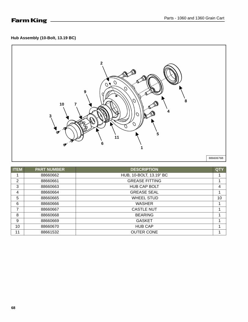
Parts - 1060 and 1360 Grain Cart
Hub Assembly (10-Bolt, 13.19 BC)
ITEM PART NUMBER DESCRIPTION QTY1 88660662 HUB, 10-BOLT, 13.19” BC 12 88660661 GREASE FITTING 13 88660663 HUB CAP BOLT 44 88660664 GREASE SEAL 15 88660665 WHEEL STUD 106 88660666 WASHER 17 88660667 CASTLE NUT 18 88660668 BEARING 19 88660669 GASKET 1
10 88660670 HUB CAP 111 88661532 OUTER CONE 1
88660676B
8
4
5
2
1
11
9
6
710
3
68

Parts - 1060 and 1360 Grain Cart
Hub & Spindle Assembly (25K)
ITEM PART NUMBER DESCRIPTION QTY1 88660676 HUB ASSEMBLY, 10 BOLT - 13.19 BC 12 88665597 SPINDLE ASSEMBLY 13 88664705 GREEN HUB & SPINDLE 25K ASSEMBLY 1
86511034 STANDARD PREMIUM PERFORMANCE PAINT -86505496 BUHLER GREEN COLOR -
4 88661527 RED HUB & SPINDLE 25K ASSEMBLY 186511034 STANDARD PREMIUM PERFORMANCE PAINT -86027517 BUHLER RED COLOR -
88661527C
2
1
3, 4
69

Parts - 1060 and 1360 Grain Cart
DRAG AUGER ASSEMBLY
Components
88662176A
11
8
10, 12
5
4
7
3
13
18 16
1917
15
14
216
23, 9
9
1
22, 9
2
70
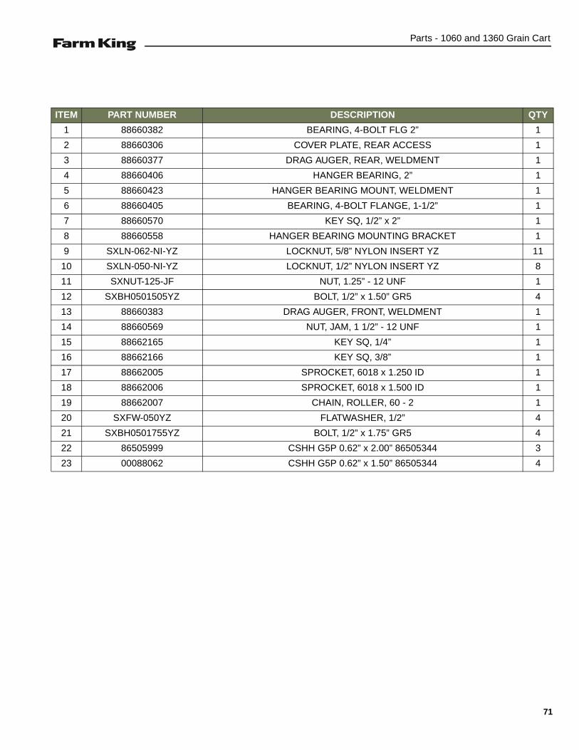
Parts - 1060 and 1360 Grain Cart
ITEM PART NUMBER DESCRIPTION QTY
1 88660382 BEARING, 4-BOLT FLG 2” 1
2 88660306 COVER PLATE, REAR ACCESS 1
3 88660377 DRAG AUGER, REAR, WELDMENT 1
4 88660406 HANGER BEARING, 2” 1
5 88660423 HANGER BEARING MOUNT, WELDMENT 1
6 88660405 BEARING, 4-BOLT FLANGE, 1-1/2” 1
7 88660570 KEY SQ, 1/2” x 2” 1
8 88660558 HANGER BEARING MOUNTING BRACKET 1
9 SXLN-062-NI-YZ LOCKNUT, 5/8” NYLON INSERT YZ 11
10 SXLN-050-NI-YZ LOCKNUT, 1/2” NYLON INSERT YZ 8
11 SXNUT-125-JF NUT, 1.25” - 12 UNF 1
12 SXBH0501505YZ BOLT, 1/2” x 1.50” GR5 4
13 88660383 DRAG AUGER, FRONT, WELDMENT 1
14 88660569 NUT, JAM, 1 1/2” - 12 UNF 1
15 88662165 KEY SQ, 1/4” 1
16 88662166 KEY SQ, 3/8” 1
17 88662005 SPROCKET, 6018 x 1.250 ID 1
18 88662006 SPROCKET, 6018 x 1.500 ID 1
19 88662007 CHAIN, ROLLER, 60 - 2 1
20 SXFW-050YZ FLATWASHER, 1/2” 4
21 SXBH0501755YZ BOLT, 1/2” x 1.75” GR5 4
22 86505999 CSHH G5P 0.62” x 2.00” 86505344 3
23 00088062 CSHH G5P 0.62” x 1.50” 86505344 4
71

Parts - 1060 and 1360 Grain Cart
DRAG AUGER GATE ASSEMBLY (1060 & 1360 MODELS)
Components
88665230B-1
18 16, 17
20
19
1512
13
14
1
2
3, 4 5
6
1
7
9
10
11
12
8
72

Parts - 1060 and 1360 Grain Cart
ITEM PART NUMBER DESCRIPTION QTY
1 88665595 COLLAR, 1.00” SHAFT SET DBL SPLT 2
2 88665217 INDICATOR SUPPORT PLATE 1
3 SXLN-031-NIYZ LOCKNUT, 5/16” NYLON INSERT YZ 1
4 SXBH0312505YZ BOLT, 5/16” x 2-1/2” GR5 YZ 1
5 88665222 GATE INDICATOR BOLT-ON WELDMENT 1
6 88665226 GATE OPEN INDICATOR ASSEMBLY 1
7 88665219 GATE INDICATOR LONG SHAFT 1
8 88663995 FLOW CONTROL GATE ASSEMBLY 1
9 88663997 RH CENTER LIFT ASSEMBLY 1
10 88665210 GATE CYLINDER LIFT WELDMENT 1
11 88664000 LH CENTER LIFT ASSEMBLY 1
12 09635076 CSHH 3/4” x 2” GR8 PLT 86505346 9
13 SXFW-075-SAE-YZ FLATWASHER, SAE 3/4” YLLWZN 4
14 88665209 BUSHING, GATE PIVOT SPACER 4
15 88665206 GATE LIFT LINK ASSEMBLY 4
16 88662125 LOCKNUT, 0.38” FL NI GR5 YZ 3
17 88662129 BOLT, 3/8” x 1.00” FLANGE GR5 3
18 88661019 SUPPORT, SHAFT WELDMENT 1
19 SXBHF0501258YZ BOLT, 1/2” x 1.50” HEX FLANGE GR8-YZ 1
20 88660954 INDICATOR, FLAT 1
73

Parts - 1060 and 1360 Grain Cart
Components (Cont’d)
ITEM PART NUMBER DESCRIPTION QTY1 SXBHF0381758YZ BOLT, 3/8” x 0.75” FLANGE GR8 YLLWZN 22 88665548 CLIP, INSULATED 0.625 CL 0.406 HOLE 43 88665549 SPACER, 5/8” OD x 0.407” ID x 1.00” 24 88662125 LOCKNUT, 0.38” FL NI GR5 YZ 105 88660067 RH STANCHION, WELDMENT 26 88660477 RH LIGHT MOUNTING BRACKET 17 88660049 REAR STANCHION, WELDMENT 18 88660478 LH LIGHT MOUNTING BRACKET 19 88660492 LOCKNUT, 3/4” NI GR5 YZ 38
10 09635076 CSHH 3/4” x 2” GR8 PLT 86505346 3811 88660063 LH STANCHION, WELDMENT 212 SXBHF0381255YZ BOLT, 3/8” x 1.25” HEX FLANGE G5 YZ 4
88665230B-2
1, 2, 3, 4
5
67
8
4, 12
9, 10
2
2
11
9, 10
74

Parts - 1060 and 1360 Grain Cart
HITCH AND JACK ASSEMBLY
Components
ITEM PART NUMBER DESCRIPTION QTY
1 88660072 HITCH MOUNT, WELDMENT 1
2 88660407 ROUND, 1.5” OD x 1.03” ID x 0.69” LG 2
3 88660495 BOLT, HEX 1.00” x 7.50” NF, GR8 Pl 5
4 88660496 BOLT, HEX 1.00” x 6.50” NF, GR8 1
5 88660497 LOCKNUT, 1.00” NYLON INSERT, NF GR8 6
6 88660499 CHAIN, AG SAFETY, 40,000 LB 1
7 88661392 HITCH, PINTLE, CAT. 4-5 CR0SSOVER 1
8 88661668 JACK, 10000 LB SIDEWIND, WELDMENT 1
9 88662159 PIN, BENT, W/HAIRPIN 1
10 88665547 CLEVIS PIN, 1" x 3 1/2” ZINC 1
11 PCT-018-225 COTTER PIN, 3/16” x 2 1/4” 1
88662175B
1
7
2
5
3
9
8
6
10
2
4
11
5
3
NOTE:
A - DRAWBAR INCLUDED IN ASSY-SINGLE AXLESTANDARD OR AS LOAD CELL IN ASSY-SINGLEAXLE SCALE.
A
75

Parts - 1060 and 1360 Grain Cart
UPPER FRAME ASSEMBLY (1060 & 1360 MODELS)
Upper Frame Components
ITEM PART NUMBER DESCRIPTION QTY
1 86508773 CB G5 P 0.38” x 1.25” 86505609 4
2 88660288 WINDOW, CLEAR, FILL LEVEL 2
3 88660289 WINDOW SEAL EDGE TRIM, 6’ 1
4 88660436 CYLINDER PIN, 1.25” x 13.38” 1
5 88660438 CYLINDER PIN, 1.25” x 15.38” 1
6 88660441 TOP AUGER PIN WELDMENT 1
7 88660470 AUGER SUPPORT WELDMENT 1
8 88660537 LADDER ASSEMBLY 1
9 88660588 BIN SPLICE PLATE 1
10 88665336 ASSY, UPPER AUGER 1
11 SX018096 ABRASION GUARD, 3.66” ID x 7’, BLK, NY 1
12 SX3NS12 STRAP, 11 1/4” BLA21 8
13 SXBHF0381008YZ BOLT, 3/8” x 1.00” FLANGE GR8 YLLWZN 6
14 SXBHF0381255YZ BOLT, 3/8” x 1.25” HEX FLANGE, G5 YZ 2
15 SXBHF0381508YZ BOLT, 3/8” x 1.50” FLANGE GR8 YLLWZN 1
16 SXNTFTL038168YZ NUT, 3/8”-16 UNC FLANGE, TP LCK, G8YZ 13
88665412
7 13, 16
14, 16
13, 16
5413, 16
15, 16
6
10
2, 3
8
1, 16
9
76
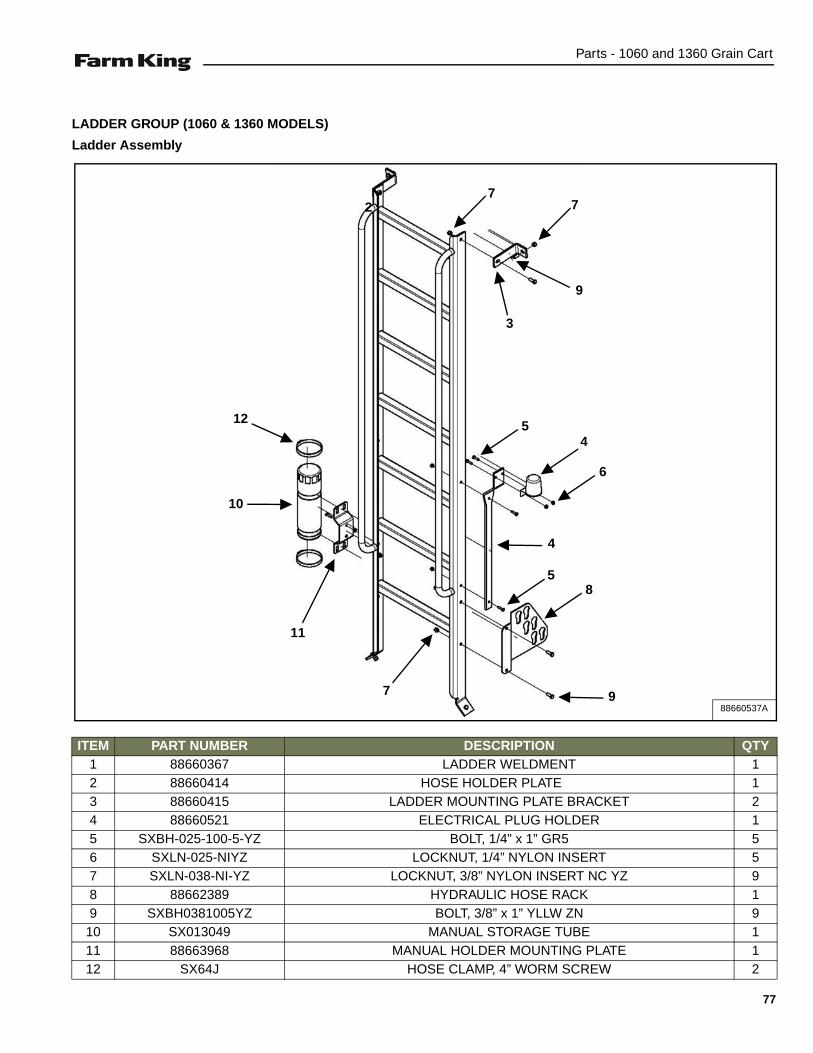
Parts - 1060 and 1360 Grain Cart
LADDER GROUP (1060 & 1360 MODELS)
Ladder Assembly
ITEM PART NUMBER DESCRIPTION QTY1 88660367 LADDER WELDMENT 12 88660414 HOSE HOLDER PLATE 13 88660415 LADDER MOUNTING PLATE BRACKET 24 88660521 ELECTRICAL PLUG HOLDER 15 SXBH-025-100-5-YZ BOLT, 1/4” x 1” GR5 56 SXLN-025-NIYZ LOCKNUT, 1/4” NYLON INSERT 57 SXLN-038-NI-YZ LOCKNUT, 3/8” NYLON INSERT NC YZ 98 88662389 HYDRAULIC HOSE RACK 19 SXBH0381005YZ BOLT, 3/8” x 1” YLLW ZN 9
10 SX013049 MANUAL STORAGE TUBE 111 88663968 MANUAL HOLDER MOUNTING PLATE 112 SX64J HOSE CLAMP, 4” WORM SCREW 2
88660537A
27
7
3
9
45
6
11
10
12
7
4
58
9
77
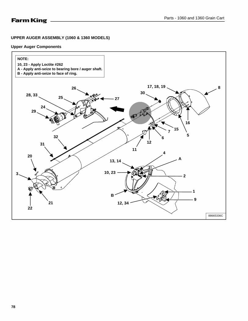
Parts - 1060 and 1360 Grain Cart
UPPER AUGER ASSEMBLY (1060 & 1360 MODELS)
Upper Auger Components
88665336C
2924
28, 3325
26
27
11
126
715
16
817, 18, 19
30
5
13, 14
4
2
1
912, 34
10, 23
20
3
2221
31
32
NOTE:
10, 23 - Apply Loctite #262A - Apply anti-seize to bearing bore / auger shaft.B - Apply anti-seize to face of ring.
A
B
78

Parts - 1060 and 1360 Grain Cart
ITEM PART NUMBER DESCRIPTION QTY
1 88665658 UPPER AUGER WELDMENT 1
2 88660360 BEARING, 4-BOLT FLG, 1-3/4” SHAFT 1
3 88660353 TOP AUGER WELDMENT 1
4 88660361 COMPRESSION SPRING 4
5 88663964 OUTLET SPOUT RING WELDMENT 1
6 88660350 SPOUT BACKPLATE, MOUNTING PLATE 4
7 88660351 NYLON SLIDE PLATE 4
8 88660326 MOLDED PLASTIC OUTLET SPOUT 1
9 88660467 AUGER CRADLE WELDMENT 1
10 88660485 WELDMENT, NUT, 1-3/4”-12 UNF 1
11 SX016809 LIGHT, SIDE, FLOOD 1
12 00080463 LOCKNUT 0.38” NC (NYLON) GR5 Pl 12
13 81967BV LOCKNUT 0.625” NC (NYLON) GRBPL 4
14 00081673 BOLT, 0.625” NC x 5.00” HEX GR5 Pl 4
15 88660352 RND, 0.62” OD x 0.38” ID x 0.62” LG 8
16 09706689 BOLT, 0.38” x 1.75” HEX GR5 Pl 8
17 SXBH-031-100-5-YZ BOLT, 5/16” x 1” GR5 YZ 8
18 SXFW-031-YZ FLAT WASHER, 5/16” YZ 16
19 SXLN-031-NIYZ LOCKNUT, 5/16” NYLON INSERT YZ 8
20 SXBH-075-900-8 BOLT, 3/4” x 9” GR8 1
21 SXLN-075-NI-YZ LOCKNUT, 3/4” NYLON INSERT YZ 1
22 88661011 DRIVEN HUB CASTING 1
23 88661414 SETSCREW, 3/8”-16 x 0.38” LG 1
24 88661414 HYDRUALIC MOTOR (Df MANIFOLD) 101-1018 1
25 88663965 ROTATE MOTOR MOUNT PLATE 1
26 SXLW-038 LOCK WASHER, 3/8” 4
27 SXLW-038 BOLT, 3/8” x 1” YLLW ZNC 4
28 SXNTFTL038168YZ NUT, 3/8”-16 UNC FLANGE, TP LCK, GR8-YZ 4
29 909169 MANIFOLD 16” Bs 1
30 88665346 ROTATION SPOUT WELDMENT 1
31 SX017978 RAIL MOUNT CLAMP, -06 DUAL LINE 3
32 88665354 HYDRAULIC TUBE, -06MJ x -06MJ x 142” 2
33 SXBHF0381258YZ BOLT, 3/8” x 1.25” FLANGE GR8 YLLWZN 4
34 SXBH0381505YZ BOLT, 3/8” x 1.50” GR5 (34 4 SXBH0381505YZ YZ) 4
79
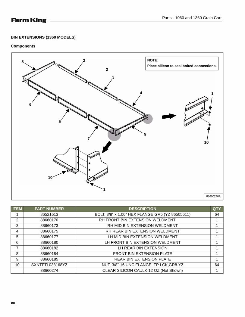
Parts - 1060 and 1360 Grain Cart
BIN EXTENSIONS (1360 MODELS)
Components
ITEM PART NUMBER DESCRIPTION QTY1 86521613 BOLT, 3/8” x 1.00” HEX FLANGE GR5 (YZ 86505611) 642 88660170 RH FRONT BIN EXTENSION WELDMENT 13 88660173 RH MID BIN EXTENSION WELDMENT 14 88660175 RH REAR BIN EXTENSION WELDMENT 15 88660177 LH MID BIN EXTENSION WELDMENT 16 88660180 LH FRONT BIN EXTENSION WELDMENT 17 88660182 LH REAR BIN EXTENSION 18 88660184 FRONT BIN EXTENSION PLATE 19 88660185 REAR BIN EXTENSION PLATE 1
10 SXNTFTL038168YZ NUT, 3/8”-16 UNC FLANGE, TP LCK,GR8-YZ 6488660274 CLEAR SILICON CAULK 12 OZ (Not Shown) 1
88660240A
2
10
10
6
5
79
4
3
28
1
1
NOTE:
Place silicon to seal bolted connections.
80

Parts - 1060 and 1360 Grain Cart
BIN SUPPORT BRACES (1060 & 1360 MODELS)
Components
ITEM PART NUMBER DESCRIPTION QTY1 00088682 CB G5P 0.38” x 1.00” 86505609 42 88660236 WHEEL PLATE BIN BRACE 13 88660237 RH LOW PLATE BIN BRACE 24 88660238 LH LOW PLATE BIN BRACE 25 88660239 RH UP PLATE BIN BRACE 26 88660241 LH UP PLATE BIN BRACE 27 88660242 BIN CROSS BRACE WELDMENT 18 88660573 EXTENSION BRACE PLATE 29 88662129 BOLT, 3/8” x 1.00” FLANGE, GR5 12
10 SXBH-050-150-5-YZ BOLT, 1/2” x 2 1/4” GR5 YZ 3211 SXBHF0381255YZ BOLT, 3/8” x 1.25” HEX FLANGE GR5 YZ 2512 SXLN-050-NI-YZ LOCKNUT, 1/2” NYLON INSERT YZ 3213 SXNTFTL038168YZ NUT, 3/8”-16 UNC FLANGE TP LCK, GR8-YZ 41
88660250A
5
7
8
6
13
11
13
12
1 610
10
12
5
2 9
13
10 311
13
10
12
4
12
10 12
81
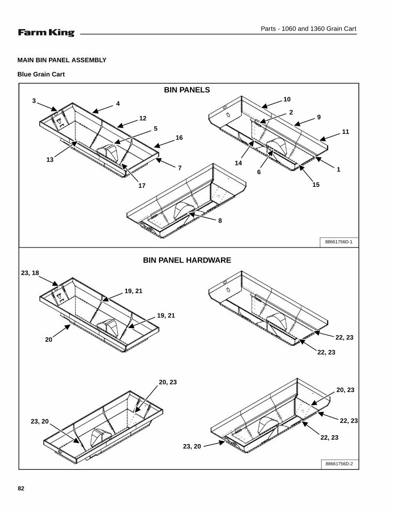
Parts - 1060 and 1360 Grain Cart
MAIN BIN PANEL ASSEMBLY
Blue Grain Cart
23, 18
20
19, 21
19, 21
22, 23
23, 20
20, 23
23, 2022, 23
22, 23
20, 23
22, 23
88661756D-2
88661756D-1
3
13
4
7
12
5
17
10
11
92
1
15
614
16
8
BIN PANELS
BIN PANEL HARDWARE
82

Parts - 1060 and 1360 Grain Cart
ITEM PART NUMBER DESCRIPTION QTY
1 88665531 BIN SPLICE PLATE 1
2 88661127 BIN REINFORCEMENT PLATE, FRMD 1
3 88662197 FRONT UPPER BIN PANEL WELDMENT 1
4 88662202 RH FRONT UPPER BIN PANEL WELDMENT 1
5 88662206 RH LOWER BIN CENTER WELDMENT 1
6 88662210 LH LOWER BIN CENTER WELDMENT 1
7 88662214 UPPER REAR BIN PANEL WELDMENT 1
8 88662219 LOWER BIN REAR WELDMENT 1
9 88662223 LH MID UPPER BIN PANEL WELDMENT 1
10 88662227 LH FRONT UPPER BIN PANEL WELDMENT 1
11 88662231 LH UPPER BIN SIDE WELDMENT 1
12 88662235 RH UPPER BIN CENTER WELDMENT 1
13 88662239 RH LOWER FRONT BIN PANEL WELDMENT 1
14 88662243 LH LOWER FRONT BIN PANEL WELDMENT 1
15 88662247 LH LOWER REAR BIN PANEL WELDMENT 1
16 88662273 RH UPPER REAR BIN SIDE WELDMENT 1
17 88662277 RH LOWER REAR BIN SIDE WELDMENT 1
18 00088682 CB G5 P 0.38” x 1.00” 86505609 63
19 SXBH0501505YZ BOLT, 1/2” x 1.50” GR5 46
20 SXBHF0381255YZ BOLT, HEX FLANGE, 3/8” x 1.25” G5 YZ 60
21 SXLN-050-NI-YZ LOCKNUT, 1/2” NYLON INSERT YZ 46
22 88662129 BOLT, FLANGE, 3/8” x 1.00” GR5 130
23 88662125 LOCKNUT, FL NI 0.38” GR5 YZ 253
88664499 SEALANT CAULK, BLUE (Not Shown) 1
83

Parts - 1060 and 1360 Grain Cart
MAIN BIN PANEL ASSEMBLY (CONT’D)
Green Grain Cart
23, 18
20
19, 21
19, 21
22, 23
23, 20
20, 23
23, 2022, 23
22, 23
20, 23
22, 23
88661756D-2
88661756D-1
3
13
4
7
12
5
17
10
11
92
1
15
614
16
8
BIN PANELS
BIN PANEL HARDWARE
84
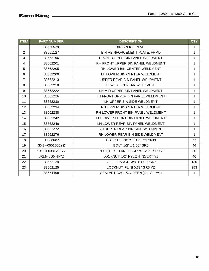
Parts - 1060 and 1360 Grain Cart
ITEM PART NUMBER DESCRIPTION QTY
1 88665529 BIN SPLICE PLATE 1
2 88661127 BIN REINFORCEMENT PLATE, FRMD 1
3 88662196 FRONT UPPER BIN PANEL WELDMENT 1
4 88662201 RH FRONT UPPER BIN PANEL WELDMENT 1
5 88662205 RH LOWER BIN CENTER WELDMENT 1
6 88662209 LH LOWER BIN CENTER WELDMENT 1
7 88662213 UPPER REAR BIN PANEL WELDMENT 1
8 88662218 LOWER BIN REAR WELDMENT 1
9 88662222 LH MID UPPER BIN PANEL WELDMENT 1
10 88662226 LH FRONT UPPER BIN PANEL WELDMENT 1
11 88662230 LH UPPER BIN SIDE WELDMENT 1
12 88662234 RH UPPER BIN CENTER WELDMENT 1
13 88662238 RH LOWER FRONT BIN PANEL WELDMENT 1
14 88662242 LH LOWER FRONT BIN PANEL WELDMENT 1
15 88662246 LH LOWER REAR BIN PANEL WELDMENT 1
16 88662272 RH UPPER REAR BIN SIDE WELDMENT 1
17 88662276 RH LOWER REAR BIN SIDE WELDMENT 1
18 00088682 CB G5 P 0.38” x 1.00” 86505609 63
19 SXBH0501505YZ BOLT, 1/2” x 1.50” GR5 46
20 SXBHF0381255YZ BOLT, HEX FLANGE, 3/8” x 1.25” G5R YZ 60
21 SXLN-050-NI-YZ LOCKNUT, 1/2” NYLON INSERT YZ 46
22 88662129 BOLT, FLANGE, 3/8” x 1.00” GR5 130
23 88662125 LOCKNUT, FL NI 0.38” GR5 YZ 253
88664498 SEALANT CAULK, GREEN (Not Shown) 1
85

Parts - 1060 and 1360 Grain Cart
MAIN BIN PANEL ASSEMBLY (CONT’D)
Red Grain Cart
23, 18
20
19, 21
19, 21
22, 23
23, 20
20, 23
23, 2022, 23
22, 23
20, 23
22, 23
88661756D-2
88661756D-1
3
13
4
7
12
5
17
10
11
92
1
15
614
16
8
BIN PANELS
BIN PANEL HARDWARE
86

Parts - 1060 and 1360 Grain Cart
ITEM PART NUMBER DESCRIPTION QTY
1 88665528 BIN SPLICE PLATE 1
2 88661127 BIN REINFORCEMENT PLATE, FRMD 1
3 88662195 FRONT UPPER BIN PANEL WELDMENT 1
4 88662200 RH FRONT UPPER BIN PANEL WELDMENT 1
5 88662204 RH LOWER BIN CENTER WELDMENT 1
6 88662208 LH LOWER BIN CENTER WELDMENT 1
7 88662212 UPPER REAR BIN PANEL WELDMENT 1
8 88662217 LOWER BIN REAR WELDMENT 1
9 88662221 LH MID UPPER BIN PANEL WELDMENT 1
10 88662225 LH FRONT UPPER BIN PANEL WELDMENT 1
11 88662229 LH UPPER BIN SIDE WELDMENT 1
12 88662233 RH UPPER BIN CENTER WELDMENT 1
13 88662237 RH LOWER FRONT BIN PANEL WELDMENT 1
14 88662241 LH LOWER FRONT BIN PANEL WELDMENT 1
15 88662245 LH LOWER REAR BIN PANEL WELDMENT 1
16 88662271 RH UPPER REAR BIN SIDE WELDMENT 1
17 88662275 RH LOWER REAR BIN SIDE WELDMENT 1
18 00088682 CB G5 P 0.38” x 1.00” 86505609 63
19 SXBH0501505YZ BOLT, 1/2” x 1.50” GR5 46
20 SXBHF0381255YZ BOLT, HEX FLANGE, 3/8” x 1.25” G5 YZ 60
21 SXLN-050-NI-YZ LOCKNUT, 1/2” NYLON INSERT YZ 46
22 88662129 BOLT, FLANGE, 3/8” x 1.00” GR5 130
23 88662125 LOCKNUT, FL NI 0.38” GR5 YZ 253
88664497 SEALANT CAULK, RED (Not Shown) 1
87

Parts - 1060 and 1360 Grain Cart
MAIN BIN PANEL ASSEMBLY (CONT’D)
Yellow Grain Cart
23, 18
20
19, 21
19, 21
22, 23
23, 20
20, 23
23, 2022, 23
22, 23
20, 23
22, 23
88661756D-2
88661756D-1
3
13
4
7
12
5
17
10
11
92
1
15
614
16
8
BIN PANELS
BIN PANEL HARDWARE
88
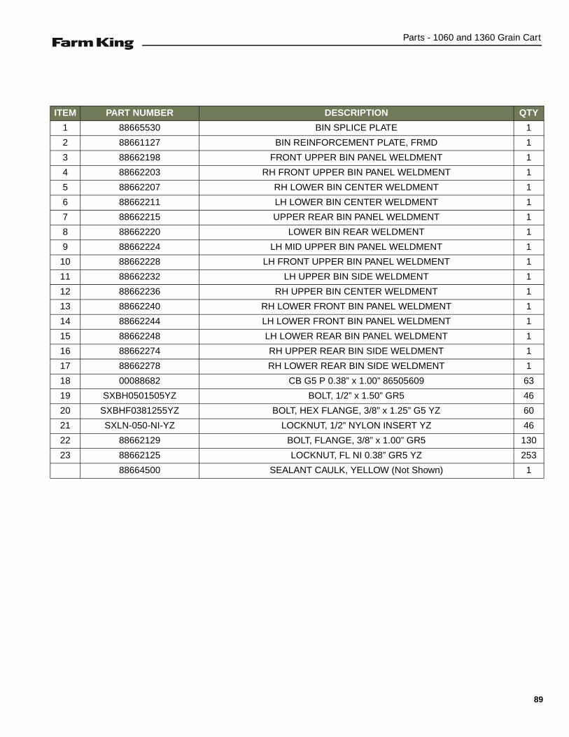
Parts - 1060 and 1360 Grain Cart
ITEM PART NUMBER DESCRIPTION QTY
1 88665530 BIN SPLICE PLATE 1
2 88661127 BIN REINFORCEMENT PLATE, FRMD 1
3 88662198 FRONT UPPER BIN PANEL WELDMENT 1
4 88662203 RH FRONT UPPER BIN PANEL WELDMENT 1
5 88662207 RH LOWER BIN CENTER WELDMENT 1
6 88662211 LH LOWER BIN CENTER WELDMENT 1
7 88662215 UPPER REAR BIN PANEL WELDMENT 1
8 88662220 LOWER BIN REAR WELDMENT 1
9 88662224 LH MID UPPER BIN PANEL WELDMENT 1
10 88662228 LH FRONT UPPER BIN PANEL WELDMENT 1
11 88662232 LH UPPER BIN SIDE WELDMENT 1
12 88662236 RH UPPER BIN CENTER WELDMENT 1
13 88662240 RH LOWER FRONT BIN PANEL WELDMENT 1
14 88662244 LH LOWER FRONT BIN PANEL WELDMENT 1
15 88662248 LH LOWER REAR BIN PANEL WELDMENT 1
16 88662274 RH UPPER REAR BIN SIDE WELDMENT 1
17 88662278 RH LOWER REAR BIN SIDE WELDMENT 1
18 00088682 CB G5 P 0.38” x 1.00” 86505609 63
19 SXBH0501505YZ BOLT, 1/2” x 1.50” GR5 46
20 SXBHF0381255YZ BOLT, HEX FLANGE, 3/8” x 1.25” G5 YZ 60
21 SXLN-050-NI-YZ LOCKNUT, 1/2” NYLON INSERT YZ 46
22 88662129 BOLT, FLANGE, 3/8” x 1.00” GR5 130
23 88662125 LOCKNUT, FL NI 0.38” GR5 YZ 253
88664500 SEALANT CAULK, YELLOW (Not Shown) 1
89

Parts - 1060 and 1360 Grain Cart
LIGHTING & MARKING
Components
ITEM PART NUMBER DESCRIPTION QTY
1 SX004561 AMBER TAIL FLASHER / WARNING LAMP 2
2 SX004560 RED TAIL / TURN LAMP 2
3 SX21294 HEAVY DUTY CABLE TIE MOUNT 9
4 SXBHF0381255YZ BOLT, 3/8” x 1.25” HEX FLANGE GR5 YZ 7
5 SXLN-038-NIYZ LOCKNUT, 3/8”, NYLON INSERT NC YZ 7
6 88660576 SMV SIGN MOUNTING PLATE 1
7 SXJD5403 SMV SIGN 1
8 SXBH0251005YZ BOLT, 1/4” x 1” GR5 2
9 SXLN-025-NIYZ LOCKNUT, 1/4” NYLON INSERT 2
10 SX3NS12 STRAP, 11-1/4” BLACK 21 9
11 88663404 NON SKID STRIP, MEDIUM GRIT 2
12 SXAC027176 NON SKID STRIP, 6” x 24” 1
88660525B-3
1
2
3, 10
4, 5
67
8, 9
11
12
11
90

Parts - 1060 and 1360 Grain Cart
SLIDE GATE ASSEMBLY
Components
ITEM PART NUMBER DESCRIPTION QTY
1 88660290 SLIDE GATE, WELDMENT 1
2 SXLN-038-NIYZ LOCKNUT, 3/8” NYLON INSERT 2
3 88660450 ROD, SLIDE, THREADED 2
4 SXLN-100-NI-YZ LOCKNUT, 1" NYLON INSERT 2
5 88660453 FLOW GATE INDICATOR, WELDMENT 1
6 00280431 N G5 P 0.50 86505597 2
7 00087936 BOLT, 3/8” x 2.50” GR5 2
8 SXPHI-100-525 HITCH PIN, 1" x 5-1/4” 1
9 SXPCT-018-150 COTTER PIN, 3/16” x 1-1/2” 3
10 SXPCL-100-300 CLEVIS PIN, 1" x 3” 1
88662174A
1
3
2, 7
5
8
9
6
6
9
4
10
91
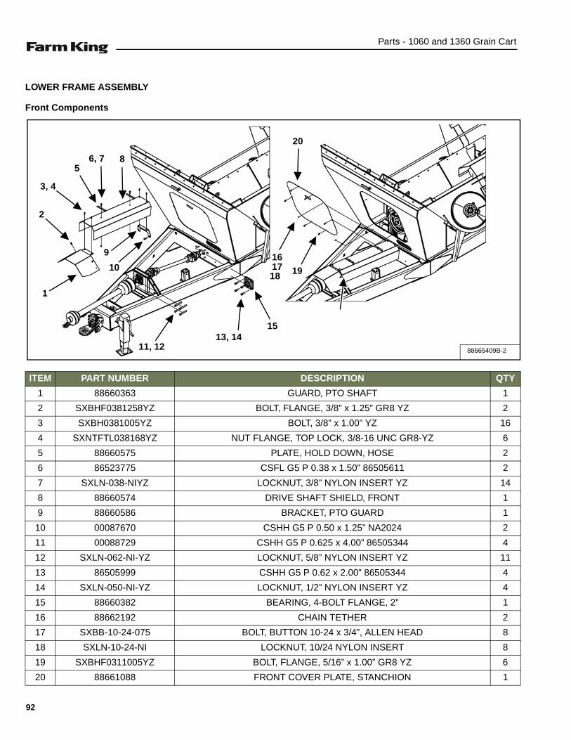
Parts - 1060 and 1360 Grain Cart
LOWER FRAME ASSEMBLY
Front Components
ITEM PART NUMBER DESCRIPTION QTY
1 88660363 GUARD, PTO SHAFT 1
2 SXBHF0381258YZ BOLT, FLANGE, 3/8” x 1.25” GR8 YZ 2
3 SXBH0381005YZ BOLT, 3/8” x 1.00” YZ 16
4 SXNTFTL038168YZ NUT FLANGE, TOP LOCK, 3/8-16 UNC GR8-YZ 6
5 88660575 PLATE, HOLD DOWN, HOSE 2
6 86523775 CSFL G5 P 0.38 x 1.50” 86505611 2
7 SXLN-038-NIYZ LOCKNUT, 3/8” NYLON INSERT YZ 14
8 88660574 DRIVE SHAFT SHIELD, FRONT 1
9 88660586 BRACKET, PTO GUARD 1
10 00087670 CSHH G5 P 0.50 x 1.25” NA2024 2
11 00088729 CSHH G5 P 0.625 x 4.00” 86505344 4
12 SXLN-062-NI-YZ LOCKNUT, 5/8” NYLON INSERT YZ 11
13 86505999 CSHH G5 P 0.62 x 2.00” 86505344 4
14 SXLN-050-NI-YZ LOCKNUT, 1/2” NYLON INSERT YZ 4
15 88660382 BEARING, 4-BOLT FLANGE, 2” 1
16 88662192 CHAIN TETHER 2
17 SXBB-10-24-075 BOLT, BUTTON 10-24 x 3/4”, ALLEN HEAD 8
18 SXLN-10-24-NI LOCKNUT, 10/24 NYLON INSERT 8
19 SXBHF0311005YZ BOLT, FLANGE, 5/16” x 1.00” GR8 YZ 6
20 88661088 FRONT COVER PLATE, STANCHION 1
88665409B-2
1
2
3, 4
56, 7 8
9
10
11, 12 13, 14
15
16
20
1718 19
92

Parts - 1060 and 1360 Grain Cart
LOWER FRAME ASSEMBLY (CONT’D)
ITEM PART NUMBER DESCRIPTION QTY
1 SXBH-075-900-8 BOLT, 3/4” x 9.00” GR8 1
2 88660492 LOCKNUT, 3/4” NI GR5 YZ 1
3 88660406 BEARING, HANGER 2" 1
4 88661014 HUB, AUGER DRIVE WELDMENT 1
5 88660423 MOUNT, HANGER BEARING, WELDMENT 1
6 SXNUT-125-JF NUT, 1.25” - 12 UNF 1
7 88660424 BRACKET, HANGER BEARING 1
8 SXBH0501755YZ BOLT, 1/2” x 1.75” GR5 6
9 SXLN-050-NI-YZ LOCKNUT, 1/2” NYLON INSERT YZ 4
10 88660337 LOWER AUGER WELDMENT 1
11 88660198 HUB, AUGER, DRIVE WELDMENT 1
12 SXBB-10-24-075 BOLT, BUTTON 10-24 x 3/4”, ALLEN HEAD 8
13 88662194 SHIELD RH DOOR ASSEMBLY 1
SX016555 LATCH, RUBBER T-HANDLE, SIZE 2.4 2
88662193 BRACE, FLAT 1
88662191 SHIELD, RH DOOR 1
14 88662192 CHAIN TETHER 2
15 SXLN-10-24-NI LOCKNUT, 10/24 NYLON INSERT 8
16 88663983 PLATE, CLEANOUT DOOR 1
17 SXBH0381005YZ BOLT, 3/8” x 1.00” YZ 16
18 SXLN-038-NIYZ LOCKNUT, 3/8” NYLON INSERT YZ 14
88665409B-3
5 6
71, 2
8, 9
10
11
12
13
12, 14, 15
1617, 18
4
3
93

Parts - 1060 and 1360 Grain Cart
LOWER FRAME ASSEMBLY (CONT’D)
PTO Hanger Mounting Components
ITEM PART NUMBER DESCRIPTION QTY1 SXBHF0622008YZ BOLT, FLANGE, 5/8” x 2.00” GR8 8
2 SXNTFTL062118Y NUT FLANGE, 5/8” - 11 GR8 8
3 88663113 BRACKET HANGER LOWER 1
4 SXBH0381005YZ BOLT, 3/8” x 1.00” YZ 16
5 SXLN-038-NIYZ LOCKNUT, 3/8” NYLON INSERT YZ 14
6 88661040 SHIELD, GEARBOX U-JOINT 1
7 00088062 CSHH G5 P.62 x 1.50” 86505344 8
8 80084057 LW P 0.625 86505602 8
9 88662012 MOUNTING BRACKET, PTO HOUSING, TOP 1
10 SXBH0501755YZ BOLT, 1/2” x 1.75” GR5 6
11 SXNTFTL050138Y NUT FLANGE, TOP LOCK, 1/2” - 13 GR8 4
88665409B-4
9
1011
1, 2
4, 5
3
6
4, 5
7, 8
94

Parts - 1060 and 1360 Grain Cart
BIN FLOOR GRATING ASSEMBLY (1060 & 1360 MODELS)
Components
ITEM PART NUMBER DESCRIPTION QTY1 88665505 REAR GRATE WELDMENT 12 88665515 FRONT GRATE WELDMENT 13 88665538 FRONT TO REAR GRATE ATTACHMENT PLATE 24 88662129 BOLT, 3/8” x 1.00” FLANGE GR5 125 88662125 LOCKNUT, 0.38” FL NI GR5 YZ 12
88665411A
4
1
2
5
3
4
5
95

Parts - 1060 and 1360 Grain Cart
CAMERA KIT (OPTIONAL) (1060 & 1360 MODELS)
Components
ITEM PART NUMBER DESCRIPTION QTY1 88664266 AGCAM CAMERA KIT 1
AGCAM CAMERA 1CAMERA BRACKET 1
36” CAMERA PIGTAIL 1SCREW, 1/4” - 20, HEX HEAD 2NYLON BRACKET WASHER 2
2 88664266 AGCAM MONITOR COMPONENTS 1AGCAM MONITOR 1
MONITOR REMOTE CONTROL 1CIGARETTE LIGHTER POWER 1
WALL POWER ADAPTOR 1MONITOR WIRE HARNESS 1
MONITOR, U-BRACKET 1U-BRACKET WING BOLTS 220’ POWER VIDEO CABLE 150’ POWER VIDEO CABLE 1
MONITOR SUNSHIELD 1
88664266
1
2
96

Parts - 1060 and 1360 Grain Cart
TARP ASSEMBLY (1060 & 1360 MODELS)
1060 Components
ITEM PART NUMBER DESCRIPTION QTY1 88662132 BOW WELDMENT, BHL CS 12 RS 90 DEG 7
88661400
1
97
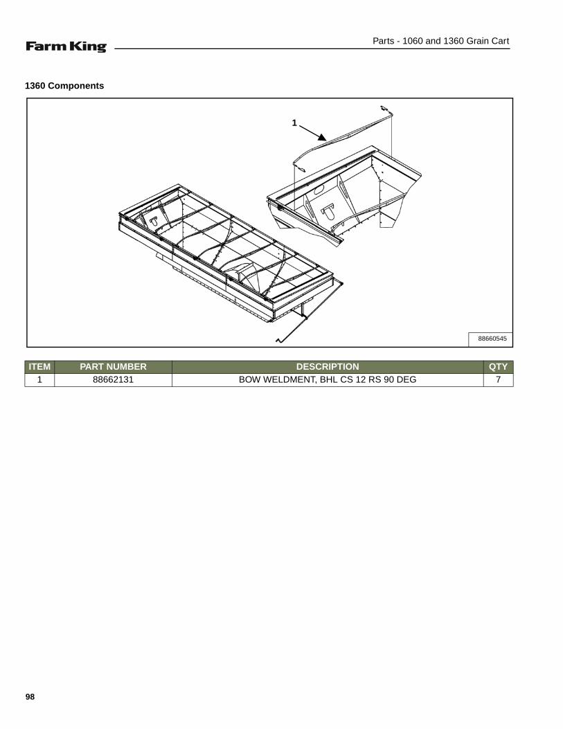
Parts - 1060 and 1360 Grain Cart
1360 Components
ITEM PART NUMBER DESCRIPTION QTY7GED 09 SR 21 SC LHB ,TNEMDLEW WOB131266881
88660545
1
98
Specifications - 1060 and 1360 Grain Cart
SPECIFICATIONS
SPECIFICATIONS . . . . . . . . . . . . . . . . . . . . . . . . . . . . . . . . . . . . . . . . . . . . . . . . . . . . . . . . . . . . . 101Dimensions . . . . . . . . . . . . . . . . . . . . . . . . . . . . . . . . . . . . . . . . . . . . . . . . . . . . . . . . . . . . . . . . 101Performance . . . . . . . . . . . . . . . . . . . . . . . . . . . . . . . . . . . . . . . . . . . . . . . . . . . . . . . . . . . . . . . 101
HYDRAULIC DIAGRAM . . . . . . . . . . . . . . . . . . . . . . . . . . . . . . . . . . . . . . . . . . . . . . . . . . . . . . . . . 102
ELECTRICAL DIAGRAM . . . . . . . . . . . . . . . . . . . . . . . . . . . . . . . . . . . . . . . . . . . . . . . . . . . . . . . . 104
ELECTRICAL SCHEMATIC . . . . . . . . . . . . . . . . . . . . . . . . . . . . . . . . . . . . . . . . . . . . . . . . . . . . . . 105
HARDWARE TORQUE VALUES . . . . . . . . . . . . . . . . . . . . . . . . . . . . . . . . . . . . . . . . . . . . . . . . . . 106Metric Chart . . . . . . . . . . . . . . . . . . . . . . . . . . . . . . . . . . . . . . . . . . . . . . . . . . . . . . . . . . . . . . . 106Imperial Chart . . . . . . . . . . . . . . . . . . . . . . . . . . . . . . . . . . . . . . . . . . . . . . . . . . . . . . . . . . . . . . 107
HYDRAULIC CONNECTION SPECIFICATIONS . . . . . . . . . . . . . . . . . . . . . . . . . . . . . . . . . . . . . .108O-Ring Fitting (Straight Thread) . . . . . . . . . . . . . . . . . . . . . . . . . . . . . . . . . . . . . . . . . . . . . . . .108O-ring Face Seal Connection . . . . . . . . . . . . . . . . . . . . . . . . . . . . . . . . . . . . . . . . . . . . . . . . . . 108Flare Fitting . . . . . . . . . . . . . . . . . . . . . . . . . . . . . . . . . . . . . . . . . . . . . . . . . . . . . . . . . . . . . . . . 108Port Seal (O-ring Boss) Fitting . . . . . . . . . . . . . . . . . . . . . . . . . . . . . . . . . . . . . . . . . . . . . . . . . 108Tubelines And Hoses . . . . . . . . . . . . . . . . . . . . . . . . . . . . . . . . . . . . . . . . . . . . . . . . . . . . . . . . 108
99

Specifications - 1060 and 1360 Grain Cart
100
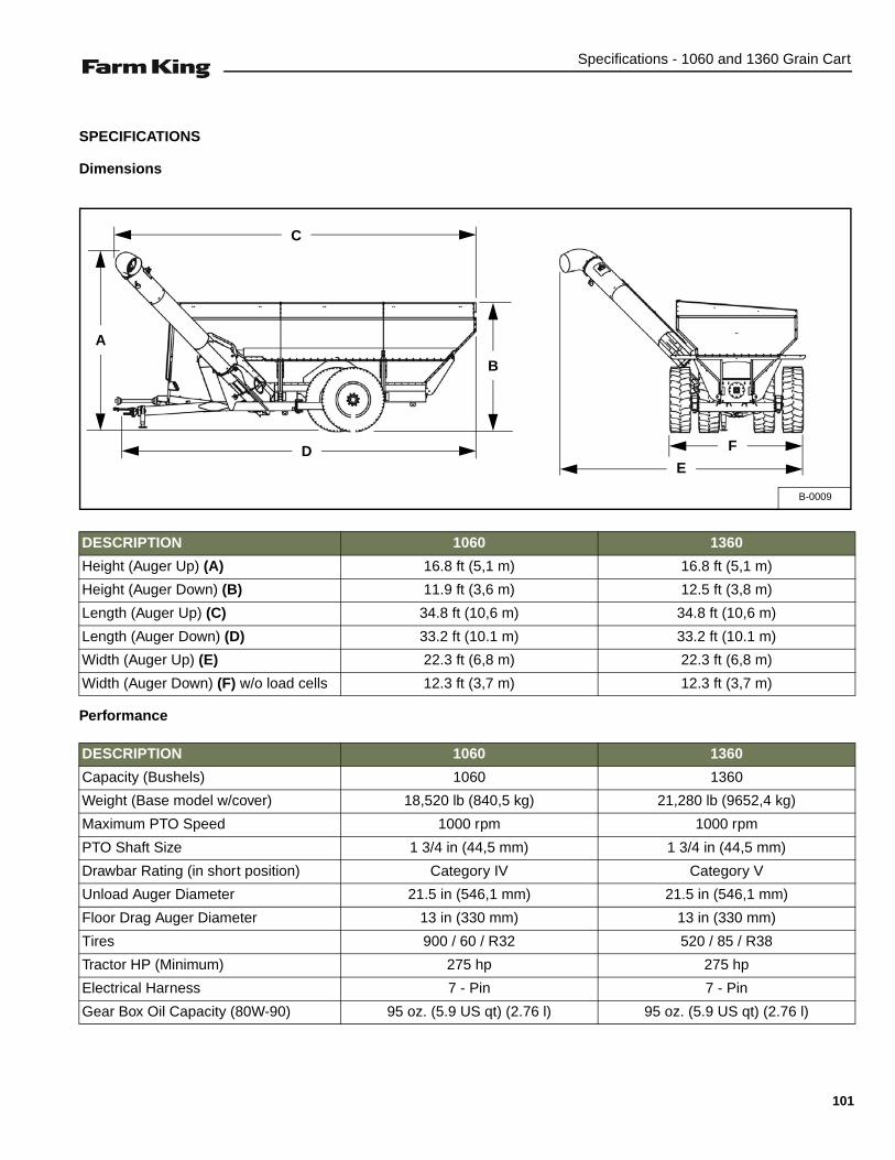
Specifications - 1060 and 1360 Grain Cart
SPECIFICATIONS
Dimensions
Performance
DESCRIPTION 1060 1360
Height (Auger Up) (A) 16.8 ft (5,1 m) 16.8 ft (5,1 m)
Height (Auger Down) (B) 11.9 ft (3,6 m) 12.5 ft (3,8 m)
Length (Auger Up) (C) 34.8 ft (10,6 m) 34.8 ft (10,6 m)
Length (Auger Down) (D) 33.2 ft (10.1 m) 33.2 ft (10.1 m)
Width (Auger Up) (E) 22.3 ft (6,8 m) 22.3 ft (6,8 m)
Width (Auger Down) (F) w/o load cells 12.3 ft (3,7 m) 12.3 ft (3,7 m)
DESCRIPTION 1060 1360
Capacity (Bushels) 1060 1360
Weight (Base model w/cover) 18,520 lb (840,5 kg) 21,280 lb (9652,4 kg)
Maximum PTO Speed 1000 rpm 1000 rpm
PTO Shaft Size 1 3/4 in (44,5 mm) 1 3/4 in (44,5 mm)
Drawbar Rating (in short position) Category IV Category V
Unload Auger Diameter 21.5 in (546,1 mm) 21.5 in (546,1 mm)
Floor Drag Auger Diameter 13 in (330 mm) 13 in (330 mm)
Tires 900 / 60 / R32 520 / 85 / R38
Tractor HP (Minimum) 275 hp 275 hp
Electrical Harness 7 - Pin 7 - Pin
Gear Box Oil Capacity (80W-90) 95 oz. (5.9 US qt) (2.76 l) 95 oz. (5.9 US qt) (2.76 l)
B-0009
C
A
D
B
F
E
101
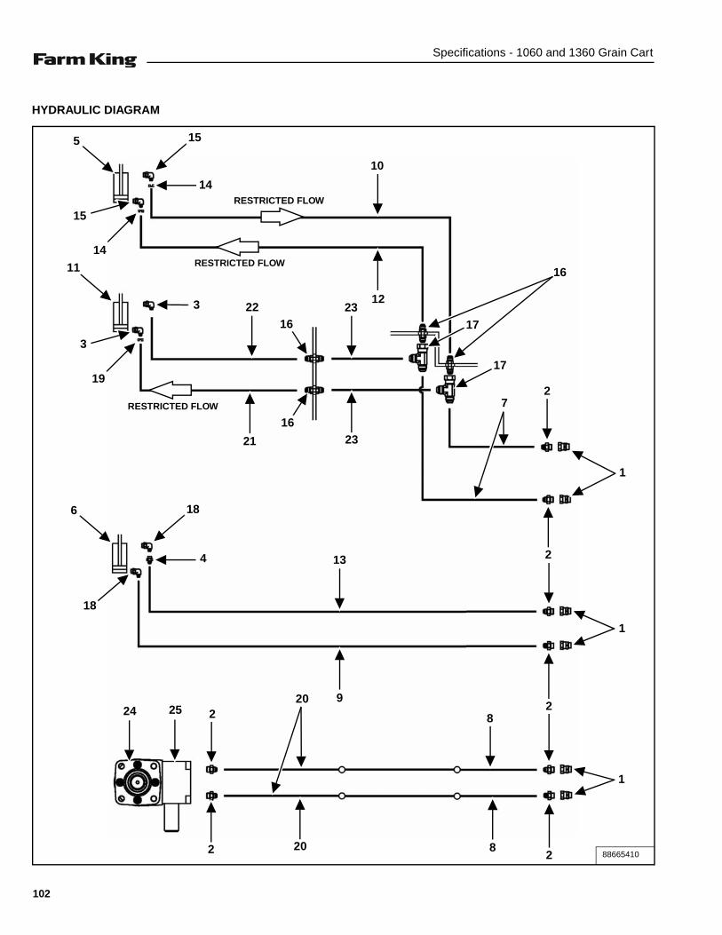
Specifications - 1060 and 1360 Grain Cart
HYDRAULIC DIAGRAM
88665410
5 15
RESTRICTED FLOW
RESTRICTED FLOW
RESTRICTED FLOW
14
14
15
10
1222 23
16
16
21 23
16
17
17
72
1
11
3
19
3
6 18
4
18
1
2
1
2
2
13
92524
2
20
82
20 8
102
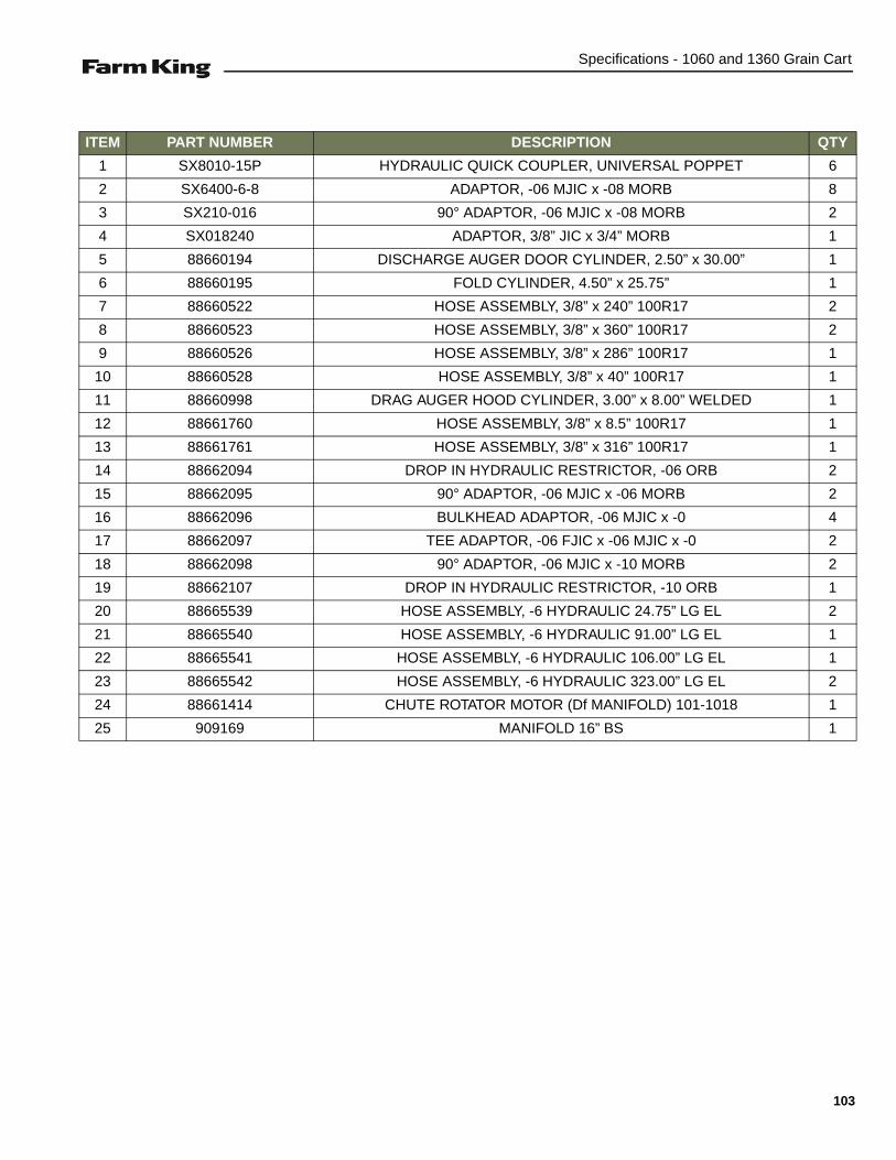
Specifications - 1060 and 1360 Grain Cart
ITEM PART NUMBER DESCRIPTION QTY
1 SX8010-15P HYDRAULIC QUICK COUPLER, UNIVERSAL POPPET 6
2 SX6400-6-8 ADAPTOR, -06 MJIC x -08 MORB 8
3 SX210-016 90° ADAPTOR, -06 MJIC x -08 MORB 2
4 SX018240 ADAPTOR, 3/8” JIC x 3/4” MORB 1
5 88660194 DISCHARGE AUGER DOOR CYLINDER, 2.50” x 30.00” 1
6 88660195 FOLD CYLINDER, 4.50” x 25.75” 1
7 88660522 HOSE ASSEMBLY, 3/8” x 240” 100R17 2
8 88660523 HOSE ASSEMBLY, 3/8” x 360” 100R17 2
9 88660526 HOSE ASSEMBLY, 3/8” x 286” 100R17 1
10 88660528 HOSE ASSEMBLY, 3/8” x 40” 100R17 1
11 88660998 DRAG AUGER HOOD CYLINDER, 3.00” x 8.00” WELDED 1
12 88661760 HOSE ASSEMBLY, 3/8” x 8.5” 100R17 1
13 88661761 HOSE ASSEMBLY, 3/8” x 316” 100R17 1
14 88662094 DROP IN HYDRAULIC RESTRICTOR, -06 ORB 2
15 88662095 90° ADAPTOR, -06 MJIC x -06 MORB 2
16 88662096 BULKHEAD ADAPTOR, -06 MJIC x -0 4
17 88662097 TEE ADAPTOR, -06 FJIC x -06 MJIC x -0 2
18 88662098 90° ADAPTOR, -06 MJIC x -10 MORB 2
19 88662107 DROP IN HYDRAULIC RESTRICTOR, -10 ORB 1
20 88665539 HOSE ASSEMBLY, -6 HYDRAULIC 24.75” LG EL 2
21 88665540 HOSE ASSEMBLY, -6 HYDRAULIC 91.00” LG EL 1
22 88665541 HOSE ASSEMBLY, -6 HYDRAULIC 106.00” LG EL 1
23 88665542 HOSE ASSEMBLY, -6 HYDRAULIC 323.00” LG EL 2
24 88661414 CHUTE ROTATOR MOTOR (Df MANIFOLD) 101-1018 1
25 909169 MANIFOLD 16” BS 1
103

Specifications - 1060 and 1360 Grain Cart
ELECTRICAL DIAGRAM
ITEM PART NUMBER DESCRIPTION QTY1 SX004560 RED TAIL / TURN LAMP 2
2 SX38204 3-PIN FEMALE METRIPAK CONNECTOR 2
3 SX38203 3-PIN MALE METRIPAK CONNECTOR 2
4 SX004561 AMBER TAIL LAMP, FLASH / WARNING 2
5 SX38201 2-PIN FEMALE METRIPAK CONNECTOR 4
6 SX38200 2-PIN MALE METRIPAK CONNECTOR 4
7 SX016809 SIDE FLOOD LIGHT 1
8 SX11 - 701 7-PIN CONNECTOR 1
9 88662413 TAIL LIGHT HARNESS 1
10 88662414 WORK LIGHT HARNESS 1
88660525B-1
1 1
4 4
6
5
6
510 9
7
6 5 6
8
2 3 23
104
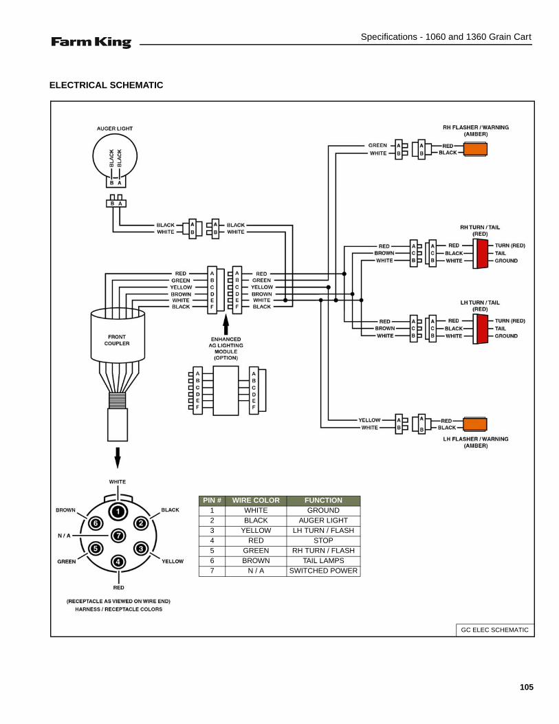
Specifications - 1060 and 1360 Grain Cart
ELECTRICAL SCHEMATIC
GC ELEC SCHEMATIC
PIN # WIRE COLOR FUNCTION1 WHITE GROUND2 BLACK AUGER LIGHT3 YELLOW LH TURN / FLASH4 RED STOP5 GREEN RH TURN / FLASH6 BROWN TAIL LAMPS7 N / A SWITCHED POWER
105

Specifications - 1060 and 1360 Grain Cart
HARDWARE TORQUE VALUES
Metric Chart
NOTE: Do not use the values listed in the charts if a different torque value or tightening procedure is specifiedin this manual for a specific application. Torque values listed are for general use only.
Use the following charts to determine the correct torque when checking, adjusting or replacing hardware. Torquevalues are listed in newton-meters (inch* or foot pounds) for normal assembly applications.
Nominal Size
Class 5.8 Class 8.8 Class 10.9 Lock nuts
Unplated PlatedW / ZnCr
Unplated PlatedW / ZnCr
Unplated PlatedW / ZnCr
CL.8 w/CL. 8.8 Bolt
M4 1.7 (15*) 2.2 (19*) 2.6 (23*) 3.4 (30*) 3.7 (33*) 4.8 (42*) 1.8 (16*)
M6 5.8 (51*) 7.6 (67*) 8.9 (79*) 12 (102*) 13 (115*) 17 (150*) 6.3 (56*)
M8 14 (124*) 18 (159*) 22 (195*) 28 (248*) 31 (274*) 40 (354*) 15 (133*)
M10 28 (21) 36 (27) 43 (32) 56 (41) 61 (45) 79 (58) 30 (22)
M12 49 (36) 63 (46) 75 (55) 97 (72) 107 (79) 138 (102) 53 (39)
M16 121 (89) 158 (117) 186 (137) 240 (177) 266 (196) 344 (254) 131 (97)
M20 237 (175) 307 (226) 375 (277) 485 (358) 519 (383) 671 (495) 265 (195)
M24 411 (303) 531 (392) 648 (478) 839 (619) 897 (662) 1160 (855) 458 (338)
NOTE: Torque values shown with * are inch pounds.
Identification of Hex Cap Screws and Carriage Bolts - Classes 5 and up
XYZ
8 8
8 8ABCD
MANUFACTURER’S IDENTIFICATION
PROPERTY CLASS
Identification of Hex Nuts and Lock Nuts - Classes 5 and up
PROPERTY CLASS
MANUFACTURER’S IDENTIFICATION
PROPERTY CLASS
AB
AB8
8 AB
106
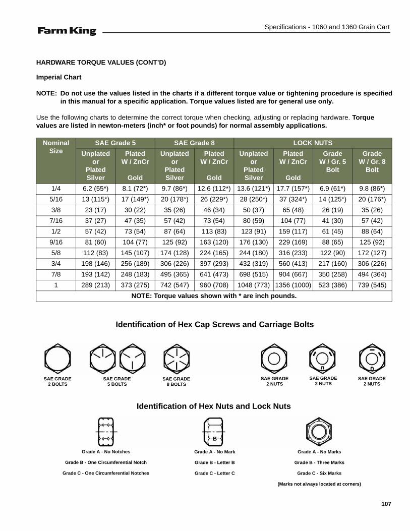
Specifications - 1060 and 1360 Grain Cart
HARDWARE TORQUE VALUES (CONT’D)
Imperial Chart
NOTE: Do not use the values listed in the charts if a different torque value or tightening procedure is specifiedin this manual for a specific application. Torque values listed are for general use only.
Use the following charts to determine the correct torque when checking, adjusting or replacing hardware. Torquevalues are listed in newton-meters (inch* or foot pounds) for normal assembly applications.
Nominal Size
SAE Grade 5 SAE Grade 8 LOCK NUTS
Unplatedor
Plated Silver
PlatedW / ZnCr
Gold
Unplatedor
Plated Silver
PlatedW / ZnCr
Gold
Unplatedor
Plated Silver
PlatedW / ZnCr
Gold
GradeW / Gr. 5
Bolt
GradeW / Gr. 8
Bolt
1/4 6.2 (55*) 8.1 (72*) 9.7 (86*) 12.6 (112*) 13.6 (121*) 17.7 (157*) 6.9 (61*) 9.8 (86*)
5/16 13 (115*) 17 (149*) 20 (178*) 26 (229*) 28 (250*) 37 (324*) 14 (125*) 20 (176*)
3/8 23 (17) 30 (22) 35 (26) 46 (34) 50 (37) 65 (48) 26 (19) 35 (26)
7/16 37 (27) 47 (35) 57 (42) 73 (54) 80 (59) 104 (77) 41 (30) 57 (42)
1/2 57 (42) 73 (54) 87 (64) 113 (83) 123 (91) 159 (117) 61 (45) 88 (64)
9/16 81 (60) 104 (77) 125 (92) 163 (120) 176 (130) 229 (169) 88 (65) 125 (92)
5/8 112 (83) 145 (107) 174 (128) 224 (165) 244 (180) 316 (233) 122 (90) 172 (127)
3/4 198 (146) 256 (189) 306 (226) 397 (293) 432 (319) 560 (413) 217 (160) 306 (226)
7/8 193 (142) 248 (183) 495 (365) 641 (473) 698 (515) 904 (667) 350 (258) 494 (364)
1 289 (213) 373 (275) 742 (547) 960 (708) 1048 (773) 1356 (1000) 523 (386) 739 (545)
NOTE: Torque values shown with * are inch pounds.
Identification of Hex Cap Screws and Carriage Bolts
Identification of Hex Nuts and Lock Nuts
SAE GRADE 2 BOLTS
SAE GRADE 5 BOLTS
SAE GRADE 8 BOLTS
SAE GRADE 2 NUTS
SAE GRADE 2 NUTS
SAE GRADE 2 NUTS
B
Grade A - No Notches
Grade B - One Circumferential Notch
Grade C - One Circumferential Notches
Grade A - No Mark
Grade B - Letter B
Grade C - Letter C
Grade A - No Marks
Grade B - Three Marks
Grade C - Six Marks
(Marks not always located at corners)
107

Specifications - 1060 and 1360 Grain Cart
HYDRAULIC CONNECTION SPECIFICATIONS
O-Ring Fitting (Straight Thread)
Lubricate the O-ring before installing the fitting. Loosenthe jam nut and install the fitting. Tighten the jam nut untilthe washer is tight against the surface.
O-ring Face Seal Connection
Figure 44
When the fitting is tightened, you can feel when the fittingis tight to eliminate leakage caused by under or overtorqued fittings. Use petroleum jelly to hold the O-ring inposition until the fittings are assembled.
Flare Fitting
Figure 45
Tighten until the nut makes contact with the seat. Use thechart [Figure 45] to find the correct tightness needed.
NOTE: If the fitting leaks, disconnect and inspect theseat area for damage.
Port Seal (O-ring Boss) Fitting
Figure 46
NOTE: Port seal and nut, washer and O-ring (O-ringBoss) fittings use the same tightening torquevalve chart.
If a torque wrench cannot be used, use the followingmethod.
Tighten the nut until it just makes metal to metal contact,you can feel the resistance.
Tighten the nut with a wrench no more than one hex flatmaximum.
Do not over tighten the port seal fitting.
NOTE: If a torque wrench cannot be used, use thehex flat tightening method as an approximateguideline.
NOTE: Port seal fittings are not recommended in allapplications. Use O-ring boss fittings in theseapplications.
Tubelines And Hoses
Replace any tubelines that are bent or flattened. They willrestrict flow, which will slow hydraulic action and causeheat.
Replace hoses which show signs of wear, damage orweather cracked rubber.
Always use two wrenches when loosening and tighteninghose or tubeline fittings.
O-ring Face Seal Tightening TorqueTubeline O.D. Thread Size N•m (ft-lb)
1/4” 9/16” - 18 13 (18)3/8” 11/16” - 16 22 (30)1/2” 13/16” - 16 40 (54)5/8” 1” - 14 60 (81)3/4” 1-3/16” - 12 84 (114)7/8” 1-3/16” - 12 98 (133)1” 1-7/16” - 12 118 (160)
1-1/4” 1-11/16” - 12 154 (209)
1-1/2” 2” - 12 163 (221)
Flare Fitting Tightening Torque
Tubeline O.D. Thread Size N•m (ft-lb)
1/4” 7/16” - 20 13 (18)
5/16” 1/2” - 20 17 (23)
3/8” 9/16” - 18 22 (30)
1/2” 3/4” - 16 40 (54)
5/8” 7/8” - 14 60 (81)
3/4” 1-1/16” - 12 84 (114)
7/8” 1-3/16” - 12 98 (133)
1” 1-5/16” - 12 118 (160)
1-1/4” 1-5/8” - 12 154 (209)
1-1/2” 1-7/8” - 12 163 (221)
2” 2-1/2” - 12 252 (342)
Port Seal And O-ring Boss Tightening Torque
Tubeline O.D. Thread Size N•m (ft-lb)
1/4” 7/16” - 20 13 (18)
3/8” 9/16” - 18 22 (30)
1/2” 3/4” -1 6 40 (54)
5/8” 7/8” - 14 60 (81)
3/4” 1-1/16” - 12 84 (114)
7/8” 1-3/16” - 12 98 (133)
1” 1-5/16” - 12 118 (160)
1-1/8” 1-7/16” - 12 154 (209)
1-1/4” 1-5/8” - 12 163 (221)
108

Warranty - 1060 and 1360 Grain Cart
WARRANTY
WARRANTY . . . . . . . . . . . . . . . . . . . . . . . . . . . . . . . . . . . . . . . . . . . . . . . . . . . . . . . . . . . . . . . . . . 111
109

Warranty - 1060 and 1360 Grain Cart
110
Warranty - 1060 and 1360 Grain Cart
WARRANTY
Limited Warranty
BASE LIMITED WARRANTY
Farm King provides this warranty only to original retail purchasers of its products. Farm King warrants to suchpurchasers that all Farm King manufactured parts and components used and serviced as provided for in theOperator’s Manual shall be free from defects in materials and workmanship for a period following delivery tothe original retail purchaser of one (1) year. This limited warranty applies only to those parts and componentsmanufactured by Farm King. Parts and components manufactured by others are subject to theirmanufacturer’s warranties, if any.
Farm King will fulfill this limited warranty by, at its option, repairing or replacing any covered part that isdefective or is the result of improper workmanship, provided that the part is returned to Farm King within thirty(30) days of the date that such defect or improper workmanship is, or should have been, discovered. Partsmust be returned through the selling representative and the buyer must prepay transportation charges.
Farm King will not be responsible for repairs or replacements that are necessitated, in whole or part, by theuse of parts not manufactured by or obtained from Farm King. Under no circumstances are component partswarranted against normal wear and tear. There is no warranty on product pump seals, product pump bearings,rubber product hoses, pressure gauges, or other components that require replacement as part of normalmaintenance.
REPAIR PARTS LIMITED WARRANTY
Farm King warrants genuine Farm King replacement parts purchased after the expiration of the Farm KingLimited Warranty, and used and serviced as provided for in the Operator’s Manual, to be free from defects inmaterials or workmanship for a period of thirty (30) days from the invoice date for the parts. Farm King willfulfill this limited warranty by, at its option, repairing or replacing any covered part that is defective or is theresult of improper workmanship, provided that the part is returned to Farm King within thirty (30) days of thedate that such defect or improper workmanship is, or should have been, discovered. Such parts must beshipped to the Farm King factory at the purchaser’s expense.
WHAT IS NOT COVERED
Under no circumstances does this limited warranty cover any components or parts that have been subject tothe following: negligence; alteration or modification not approved by Farm King; misuse; improper storage;lack of reasonable and proper maintenance, service, or repair; normal wear; damage from failure to followoperating instructions; accident; and/or repairs that have been made with parts other than thosemanufactured, supplied, and or authorized by Farm King.
AUTHORIZED DEALER AND LABOR COSTS
Repairs eligible for labor under this limited warranty must be made by Farm King or an authorized Farm Kingdealer. Farm King retains the exclusive discretion to determine whether it will pay labor costs for warrantyrepairs or replacements, and the amount of such costs that it will pay and the time in which the repairs will bemade. If Farm King determines that it will pay labor costs for warranty work, it will do so by issuing a credit tothe dealer’s or distributor’s account. Farm King will not approve or pay invoices sent for repairs that Farm Kinghas not previously approved. Warranty service does not extend the original term of this limited warranty.
111
Warranty - 1060 and 1360 Grain Cart
Limited Warranty
WARRANTY REQUIREMENTS
To be covered by warranty, each new product must be registered with Farm King within thirty (30) days ofdelivery to original retail purchaser. If the customer decides to purchase replacement components before thewarranty disposition of such components is determined, Farm King will bill the customer for suchcomponents and then credit the replacement invoice for those components later determined to be covered bythis limited warranty. Any such replacement components that are determined not be covered by this limitedwarranty will be subject to the terms of the invoice and shall be paid for by the purchaser.
EXCLUSIVE EFFECT OF WARRANTY AND LIMITATION OF LIABILITY
TO THE EXTENT PERMITTED BY LAW, FARM KING DISCLAIMS ANY WARRANTIES, REPRESENTATIONS, ORPROMISES, EXPRESS OR IMPLIED, AS TO THE QUALITY, PERFORMANCE, OR FREEDOM FROM DEFECT OFTHE COMPONENTS AND PARTS COVERED BY THIS WARRANTY AND NOT SPECIFICALLY PROVIDED FORHEREIN.
TO THE EXTENT PERMITTED BY LAW, FARM KING DISCLAIMS ANY IMPLIED WARRANTIES OFMERCHANTABILITY AND FITNESS FOR A PARTICULAR PURPOSE ON ITS PRODUCTS COVERED HEREIN,AND DISCLAIMS ANY RELIANCE BY THE PURCHASER ON FARM KING’S SKILL OR JUDGMENT TO SELECTOR FURNISH GOODS FOR ANY PARTICULAR PURPOSE. THE PURCHASER’S ONLY AND EXCLUSIVEREMEDIES IN CONNECTION WITH THE BREACH OR PERFORMANCE OF ANY WARRANTY ON FARM KING’SProduct S ARE THOSE SET FORTH HEREIN. IN NO EVENT SHALL FARM KING BE LIABLE FOR INCIDENTALOR CONSEQUENTIAL DAMAGES (INCLUDING, BY WAY OF EXAMPLE ONLY AND NOT LIMITATION, LOSS OFCROPS, LOSS OF PROFITS OR REVENUE, OTHER COMMERCIAL LOSSES, INCONVENIENCE, OR COST OFREPLACEMENT OF RENTAL EQUIPMENT). IN NO EVENT SHALL FARM KING’S CONTRACT OR WARRANTYLIABILITY EXCEED THE PURCHASE PRICE OF THE PRODUCT. (Note that some states do not allow limitationson how long an implied warranty lasts or the exclusion or limitation of incidental or consequential damages,so the above limitations and exclusion may not apply to you.) This warranty gives you specific legal rights andyou may also have other rights, which vary from state to state.
Farm King neither assumes nor authorizes any person or entity, including its selling representatives, toassume any other obligations or liability in connections with the sale of covered equipment, or to make anyother warranties, representations, or promises, express or implied, as to the quality, performance, or freedomfrom defect of the components and parts covered herein. No one is authorized to alter, modify, or enlarge thislimited warranty, or its exclusions, limitations and reservations.
Corrections of defects and improper workmanship in the manner, and for the applicable time periods, providedfor herein shall constitute fulfillment of all responsibilities of Farm King to the purchaser, and Farm King shallnot be liable in negligence, contract, or on any other basis with respect to the subject equipment.
This limited warranty is subject to any existing conditions of supply which may directly affect Farm King’sability to obtain materials or manufacturer replacement parts.
Buhler Industries Inc. reserves the right to make improvements in design or changes in specifications to itsproducts at anytime, without incurring any obligation to owners of units previously sold.
112
Alphabetical Index - 1060 and 1360 Grain Cart
ALPHABETICAL INDEX
AXLE & HITCH OPTIONS (1060 & 1360 MODELS) . . . . . . . . . . . . . . . . . . . . . . . . . . . 58BIN EXTENSIONS (1360 MODELS) . . . . . . 80BIN FLOOR GRATING ASSEMBLY (1060 & 1360 MODELS) . . . . . . . . . . . . . . . . . . . . . . 95BIN SUPPORT BRACES (1060 & 1360 MODELS) . . . . . . . . . . . . . . . . . . . . . . . . . . . 81CAMERA KIT (OPTIONAL) (1060 & 1360 MODELS) . . . . . . . . . . . . . . . . . . . . . . . . . . . 96DRAG AUGER ASSEMBLY . . . . . . . . . . . . . 70DRAG AUGER BELT DRIVE . . . . . . . . . . . . 46DRAG AUGER GATE ASSEMBLY (1060 & 1360 MODELS) . . . . . . . . . . . . . . . . . . . . . . 72DRIVE GROUP (1060 & 1360 MODELS) . . 53ELECTRICAL DIAGRAM . . . . . . . . . . . . . . 104ELECTRICAL SCHEMATIC . . . . . . . . . . . . 105EQUIPMENT DECALS AND SIGNS . . . . . . 19EQUIPMENT IDENTIFICATION . . . . . . . . . . . 8FIRE PREVENTION . . . . . . . . . . . . . . . . . . . 14GENERAL INFORMATION . . . . . . . . . . . . . 25GENERAL INFORMATION . . . . . . . . . . . . . 53GRAIN CART OPERATION . . . . . . . . . . . . . 31HARDWARE TORQUE VALUES . . . . . . . . 106HITCH AND JACK ASSEMBLY . . . . . . . . . . 75HYDRAULIC CONNECTION SPECIFICATIONS . . . . . . . . . . . . . . . . . . . 108HYDRAULIC DIAGRAM . . . . . . . . . . . . . . . 102INITIAL SET-UP . . . . . . . . . . . . . . . . . . . . . . 28LADDER GROUP (1060 & 1360 MODELS) . 77LIGHTING & MARKING . . . . . . . . . . . . . . . . 90LOWER FRAME ASSEMBLY . . . . . . . . . . . . 92LUBRICATION . . . . . . . . . . . . . . . . . . . . . . . 42MAIN BIN PANEL ASSEMBLY . . . . . . . . . . . 82OWNER’S INFORMATION . . . . . . . . . . . . . . . 7PTO DRIVELINE . . . . . . . . . . . . . . . . . . . . . 47SAFETY INSTRUCTIONS . . . . . . . . . . . . . . 11SAFETY SIGN (DECAL) INSTALLATION . . 49SAFETY SIGN-OFF FORM . . . . . . . . . . . . . 21SAFETY SIGNS (DECALS) . . . . . . . . . . . . . 16SERVICE SCHEDULE . . . . . . . . . . . . . . . . . 41
SINGLE AXLE . . . . . . . . . . . . . . . . . . . . . . . 49SLIDE GATE ASSEMBLY . . . . . . . . . . . . . . . 91SPECIFICATIONS . . . . . . . . . . . . . . . . . . . 101STORAGE AND RETURN TO SERVICE . . . 49TANDEM AXLE . . . . . . . . . . . . . . . . . . . . . . . 48TARP ASSEMBLY (1060 & 1360 MODELS) .97TRANSPORTING . . . . . . . . . . . . . . . . . . . . . 36TROUBLESHOOTING . . . . . . . . . . . . . . . . . 39UPPER AUGER ASSEMBLY (1060 & 1360 MODELS) . . . . . . . . . . . . . . . . . . . . . . . . . . . 78UPPER FRAME ASSEMBLY (1060 & 1360 MODELS) . . . . . . . . . . . . . . . . . . . . . . . . . . . 76WARRANTY REGISTRATION FORM . . . . . . 3WARRANTY . . . . . . . . . . . . . . . . . . . . . . . .111
113

Alphabetical Index - 1060 and 1360 Grain Cart
114


2500 Airport Drive SWWillmar, MN USA 56201Toll Free: 1-888-FK-80001 E-mail: [email protected]
Equipment shown is subject to change without notice.©2012 Buhler Trading Inc. Printed in Canada TSX:BUI
www.farm-king.com