OPERATIONAL PROPERTY DESIGN AND … · BS EN 12056-3: 2000 - Gravity drainage inside buildings:...
21
OPERATIONAL PROPERTY DESIGN AND CONSTRUCTION HANDBOOK STATIONS GOVERNING PRINCIPLES > CANOPIES Page | STN:13-1 Network Rail 13 CANOPIES Contents 13.1 DESIGN AIMS ........................................................ 13‐2 13.2 POLICY, PERFORMANCE & COMPLIANCE ............... 13‐3 13.2.1 APPLICABLE STANDARDS ..............................................13‐3 13.2.1.1 BS & EN Standards .........................................13‐3 13.2.1.2 The Building Regulations................................13‐3 13.2.1.3 Department for Transport ..............................13‐3 13.2.1.4 Rail Safety and Standards Board....................13‐3 13.2.1.5 Network Rail Standards .................................13‐4 13.2.1.6 Other ..............................................................13‐4 13.3 CIVIL DESIGN PRINCIPLES & CONSTRAINTS ............ 13‐5 13.3.1 GENERAL ...................................................................13‐5 13.3.2 GEOMETRY AND CLEARANCES........................................13‐5 13.3.3 DESIGN .....................................................................13‐5 13.3.4 ANALYSIS ..................................................................13‐5 13.3.5 CONNECTIONS ............................................................13‐5 13.3.6 COLUMNS .................................................................13‐6 13.3.7 FOUNDATIONS ...........................................................13‐6 13.3.8 FABRICATION CONSIDERATIONS .....................................13‐6 13.3.9 COVERING .................................................................13‐6 13.3.9.1 Cladding Sheeting ..........................................13‐6 13.3.9.2 Glazing ...........................................................13‐6 13.3.10 SUSTAINABILITY ..........................................................13‐6 13.3.11 OTHER SERVICES .........................................................13‐6 13.3.12 SPECIFIC CONSTRAINTS ................................................13‐7 13.3.12.1 Tolerances ......................................................13‐7 13.3.12.2 Steelwork Finishing’s ......................................13‐7 13.3.13 MAINTENANCE ...........................................................13‐7 13.4 STANDARD & GENERAL DETAILS............................ 13‐8 13.4.1 SURFACE DRAINAGE ....................................................13‐8 13.4.1.1 Drainage Downpipes ......................................13‐8 13.4.1.2 Drainage Gutter (Lined) .................................13‐8 13.4.1.3 Drainage Gutter (unlined) ..............................13‐9 13.4.1.4 Valley and Parapet Gutters: .........................13‐10 13.4.1.5 Drainage Hopper: .........................................13‐10 13.4.2 EXTERNAL JOINERY DETAILS ........................................13‐10 13.4.2.1 External Fascia Board:..................................13‐10 13.4.2.2 External Soffit or Ceiling Boarding ...............13‐11 13.4.2.3 External Valence ..........................................13‐11 13.4.3 MAINTENANCE,ACCESS &SAFETY EQUIPMENT ..............13‐11 13.4.3.1 Access (Horizontal):......................................13‐11 13.4.3.2 Access (Vertical): ..........................................13‐11 13.4.3.3 Access Restraint ...........................................13‐11 13.4.4 STRUCTURAL ............................................................13‐12 13.4.4.1 Beams, Girders, Joists & Purlins ...................13‐12 13.4.4.2 Deck or Floor: ...............................................13‐12 13.4.4.3 Space Frames:.............................................. 13‐12 13.4.4.4 Lattice Trusses: ............................................ 13‐12 13.4.4.5 Cantilever Support: ...................................... 13‐12 13.4.4.6 Columns ....................................................... 13‐12 13.4.4.7 Architectural Glazing: .................................. 13‐12 13.4.4.8 Cladding:...................................................... 13‐13 13.4.4.9 Foundations: ................................................ 13‐13 13.4.4.10 Typical Details and Examples ...................... 13‐14 13.5 M&E DESIGN PRINCIPLES & CONSTRAINTS .......... 13‐15 13.5.1 GENERAL ................................................................ 13‐15 13.6 LIGHTING AND EMERGENCY LIGHTING ................ 13‐15 13.6.1 COLUMNS ............................................................... 13‐15 13.6.2 LUMINAIRES ............................................................ 13‐15 13.6.3 LIGHTING CONTROL .................................................. 13‐15 13.7 SMALL POWER .................................................... 13‐16 13.7.1 ACCESSORIES ........................................................... 13‐16 13.8 FIRE ALARM ........................................................ 13‐16 13.8.1 EQUIPMENT ............................................................ 13‐16 13.9 ANCILLARY SERVICES........................................... 13‐16 13.9.1 GENERAL ................................................................ 13‐16 13.10 CABLES AND CONTAINMENT ............................... 13‐16 13.11 EARTHING AND LIGHTNING PROTECTION ............ 13‐17 13.12 TESTING AND COMMISSIONING .......................... 13‐17 13.13 O&M MANUALS .................................................. 13‐17 13.14 MECHANICAL ...................................................... 13‐18 13.14.1 GENERAL ................................................................ 13‐18 13.14.2 TESTING AND COMMISSIONING ................................... 13‐18 13.14.3 OPERATION AND MAINTENANCE MANUALS................... 13‐18 13.14.4 SPECIFIC CONSTRAINTS .............................................. 13‐18 13.15 SPECIFICATIONS AND GUIDANCE ......................... 13‐19 13.15.1 MODEL CLAUSES ...................................................... 13‐19 13.15.2 USEFUL SPECIFICATIONS ............................................ 13‐19 13.15.3 USEFUL GUIDANCE ................................................... 13‐19 13.16 PRODUCT DATA .................................................. 13‐19 13.17 DRAWINGS ......................................................... 13‐20 13.17.1 CIVIL ...................................................................... 13‐20 13.17.2 MECHANICAL &ELECTRICAL ....................................... 13‐21 Close | Print | MAIN CONTENT | STATION CONTENT Previous Part | Previous Page | Next Page
Transcript of OPERATIONAL PROPERTY DESIGN AND … · BS EN 12056-3: 2000 - Gravity drainage inside buildings:...

OPERATIONAL PROPERTY DESIGN AND CONSTRUCTION HANDBOOK
STATIONS GOVERNING PRINCIPLES > CANOPIES
Page | STN:13-1
Network Rail
13 CANOPIES
Contents
13.1 DESIGN AIMS ........................................................ 13‐2
13.2 POLICY, PERFORMANCE & COMPLIANCE ............... 13‐3
13.2.1 APPLICABLE STANDARDS ..............................................13‐3 13.2.1.1 BS & EN Standards .........................................13‐3 13.2.1.2 The Building Regulations................................13‐3 13.2.1.3 Department for Transport..............................13‐3 13.2.1.4 Rail Safety and Standards Board....................13‐3 13.2.1.5 Network Rail Standards .................................13‐4 13.2.1.6 Other ..............................................................13‐4
13.3 CIVIL DESIGN PRINCIPLES & CONSTRAINTS ............ 13‐5
13.3.1 GENERAL...................................................................13‐5 13.3.2 GEOMETRY AND CLEARANCES........................................13‐5 13.3.3 DESIGN .....................................................................13‐5 13.3.4 ANALYSIS ..................................................................13‐5 13.3.5 CONNECTIONS............................................................13‐5 13.3.6 COLUMNS .................................................................13‐6 13.3.7 FOUNDATIONS ...........................................................13‐6 13.3.8 FABRICATION CONSIDERATIONS .....................................13‐6 13.3.9 COVERING .................................................................13‐6 13.3.9.1 Cladding Sheeting ..........................................13‐6 13.3.9.2 Glazing ...........................................................13‐6
13.3.10 SUSTAINABILITY ..........................................................13‐6 13.3.11 OTHER SERVICES.........................................................13‐6 13.3.12 SPECIFIC CONSTRAINTS ................................................13‐7 13.3.12.1 Tolerances ......................................................13‐7 13.3.12.2 Steelwork Finishing’s......................................13‐7
13.3.13 MAINTENANCE...........................................................13‐7
13.4 STANDARD & GENERAL DETAILS............................ 13‐8
13.4.1 SURFACE DRAINAGE ....................................................13‐8 13.4.1.1 Drainage Downpipes......................................13‐8 13.4.1.2 Drainage Gutter (Lined) .................................13‐8 13.4.1.3 Drainage Gutter (unlined) ..............................13‐9 13.4.1.4 Valley and Parapet Gutters: .........................13‐10 13.4.1.5 Drainage Hopper:.........................................13‐10
13.4.2 EXTERNAL JOINERY DETAILS ........................................13‐10 13.4.2.1 External Fascia Board:..................................13‐10 13.4.2.2 External Soffit or Ceiling Boarding ...............13‐11 13.4.2.3 External Valence ..........................................13‐11
13.4.3 MAINTENANCE, ACCESS & SAFETY EQUIPMENT ..............13‐11 13.4.3.1 Access (Horizontal):......................................13‐11 13.4.3.2 Access (Vertical): ..........................................13‐11 13.4.3.3 Access Restraint ...........................................13‐11
13.4.4 STRUCTURAL ............................................................13‐12 13.4.4.1 Beams, Girders, Joists & Purlins ...................13‐12 13.4.4.2 Deck or Floor: ...............................................13‐12
13.4.4.3 Space Frames:.............................................. 13‐12 13.4.4.4 Lattice Trusses: ............................................ 13‐12 13.4.4.5 Cantilever Support: ...................................... 13‐12 13.4.4.6 Columns ....................................................... 13‐12 13.4.4.7 Architectural Glazing: .................................. 13‐12 13.4.4.8 Cladding:...................................................... 13‐13 13.4.4.9 Foundations:................................................ 13‐13 13.4.4.10 Typical Details and Examples ...................... 13‐14
13.5 M&E DESIGN PRINCIPLES & CONSTRAINTS .......... 13‐15
13.5.1 GENERAL ................................................................ 13‐15
13.6 LIGHTING AND EMERGENCY LIGHTING ................ 13‐15
13.6.1 COLUMNS ............................................................... 13‐15 13.6.2 LUMINAIRES ............................................................ 13‐15 13.6.3 LIGHTING CONTROL .................................................. 13‐15
13.7 SMALL POWER.................................................... 13‐16
13.7.1 ACCESSORIES ........................................................... 13‐16
13.8 FIRE ALARM........................................................ 13‐16
13.8.1 EQUIPMENT ............................................................ 13‐16
13.9 ANCILLARY SERVICES........................................... 13‐16
13.9.1 GENERAL ................................................................ 13‐16
13.10 CABLES AND CONTAINMENT ............................... 13‐16
13.11 EARTHING AND LIGHTNING PROTECTION............ 13‐17
13.12 TESTING AND COMMISSIONING.......................... 13‐17
13.13 O&M MANUALS.................................................. 13‐17
13.14 MECHANICAL ...................................................... 13‐18
13.14.1 GENERAL ................................................................ 13‐18 13.14.2 TESTING AND COMMISSIONING ................................... 13‐18 13.14.3 OPERATION AND MAINTENANCE MANUALS................... 13‐18 13.14.4 SPECIFIC CONSTRAINTS.............................................. 13‐18
13.15 SPECIFICATIONS AND GUIDANCE......................... 13‐19
13.15.1 MODEL CLAUSES ...................................................... 13‐19 13.15.2 USEFUL SPECIFICATIONS ............................................ 13‐19 13.15.3 USEFUL GUIDANCE ................................................... 13‐19
13.16 PRODUCT DATA .................................................. 13‐19
13.17 DRAWINGS ......................................................... 13‐20
13.17.1 CIVIL ...................................................................... 13‐20 13.17.2 MECHANICAL & ELECTRICAL ....................................... 13‐21
Close | Print | MAIN CONTENT | STATION CONTENT Previous Part | Previous Page | Next Page
OPERATIONAL PROPERTY DESIGN AND CONSTRUCTION HANDBOOK
STATIONS GOVERNING PRINCIPLES > CANOPIES
Page | STN:13-2
Network Rail
13.1 Design Aims The design aim is to utilise where practical former designs and details that have been successfully adopted at other NWR stations and to comply with the current applicable NWR Standards, British Standards and Eurocodes. This handbook contains a number of typical design solutions for use by the designer in developing designs where the provision of new or extended canopy is a particular requirement of the project. All canopies should be designed to comply with all current applicable standards and to meet any particular requirements of the project concerned identified by Network Rail’s Project Management Team. Possession and access availability for construction purposes are particular concerns when considering works, such as platform canopy constructions ‘on or near the line’. In selecting a design detail consideration should be given to construction details that mitigate any potential disruption to the operational railway. The design life of the canopy structures shall be 60 years to first maintenance. Safety and security is of paramount importance and is a legal obligation on the railway and to the travelling public and those that service and maintain the infrastructure. Strategies, procedures and regimes must be clearly thought out and documented in contract documentation. Where required reference must be made to Group Standards for operational clearances. www.rgsonline.co.uk Existing service and archive records should be obtained either via Network Rail or directly from the relevant organisations for the site concerned Detailed topographical surveys and ground investigations (to establish ground conditions, allowable bearing pressures, infiltration rates, chemical composition and contaminants) shall be undertaken to ascertain as much information as possible on the existing site and on any existing structures and installations likely to be affected by the proposed works prior to commencement of the design works. Environmental and ecological surveys will need to be undertaken to establish any constraints that may be imposed upon the site that may have a direct impact on the proposed canopy development or works
The design shall take cognisance of existing ground conditions, existing buried services and station location such as proximity to the sea. In selecting details the designer should do so in full knowledge of the requirements for the project to ensure compliance to specification, planning and aesthetic appearance and to any other specific requirements identified by the client for the project. It is the responsibility of the designer to ensure that the selected detail is not only compliant but is also appropriate for the required situation. Whilst not an exhaustive list, when developing a ‘non-standard’ platform canopy design, consideration will need to be given to the achieving the following design aims: - Identify the type of canopy required by the project,
platform, building, single span or double canterlever, spanning a terminating or bay platform etc.
The location should be appropriate to the requirements of
the project and consider the effects being located on a straight or curve and avoid effecting the signal sighting.
Consideration should also be given to the aesthetic
appearance of the platform canopy structure against the surrounding environment including the selection of appropriate, sympathetic construction (steel/timber/cast iron/concrete etc) and finishing materials and methods.
Due consideration is to be given to any particular planning
constraints or requirements such as visual aspects and historic building listings, conservation areas and be agreed with local planning authorities via Network Rail.
Identify and make adequate allowance for access
availability for construction purposes – is access readily available or will temporary access measures/structures be required and will any approvals or special arrangements be required to facilitate the construction works. Access availability may influence the type of construction.
Close | Print | STATION CONTENT | CANOPIES CONTENT Previous View | Previous Page | Next Page

OPERATIONAL PROPERTY DESIGN AND CONSTRUCTION HANDBOOK
STATIONS GOVERNING PRINCIPLES > CANOPIES
Page | STN:13-3
Network Rail
13.2 Policy, Performance & Compliance Canopy designs should be undertaken in accordance with the relevant British standards, Eurocodes and NWR Standards as listed below:
13.2.1 Applicable Standards
13.2.1.1 BS & EN Standards BS EN 1990 - Eurocode: Basis of structural design. BS EN 1991 - Eurocode 1: Actions on structures. BS EN 1992 - Eurocode 2: Design of concrete structures. BS EN 1993 - Eurocode 3: Design of steel structures. BS EN 1994 - Eurocode 4: Design of composite
structures. BS EN 1995 - Eurocode 5: Design of timber structures. BS EN 1996 - Eurocode 6: Design of masonry structures. BS EN 1997 - Eurocode 7: Geotechnical design. BS EN 206 – Concrete. BS EN 12588 Code 5 Lead. BS EN 14122 Parts 1-4 incl. 2001-2004. BS EN 485-1: 1994 - Specification for aluminium alloys -
sheet, strip and plate. BS 1474: 1987 - Specification for wrought aluminium and
aluminium alloys for general engineering purposes: bars, extruded tubes and sections.
BS 1490: 1970 - Specification for cast aluminium gutters and fittings.
BS EN 1462: 1997 - Specification for support brackets for aluminium gutters.
BS EN 12056-3: 2000 - Gravity drainage inside buildings: Roof drainage, layout and calculation.
BS 648 1964 – Schedule of Weights of Building Materials. BS 5950 – 1: 2000 - Structural Use of Steelwork in
Building. BS 6399 – 1, 2, 3 - Loadings for Building. BS 5395 – 1: 2000 - Stairs, Ladders and Walkways. BS 8110 – 1,2 - Code of Practice for use of Concrete. BS 8004 – Code of Practice for Foundations. BS 8300:2009 - Design of buildings and their approaches
to meet the needs of disabled people. Code of practice BS 5266 Code of practice Emergency Lighting BS 5489 Design of Road Lighting BS 5839 Fire Detection and Alarm Systems BS7671:2008 I.E.E. Regulations for Electrical Installations BS 50122 & BS7430 Earthing and bonding including
Touch Potential BS 6651 Code of practice Lightning Protection BS EN 12464-2 2002 Lighting of Workplaces – Part 2
Outdoor BS EN 50121:2006 Railway Applications –
Electromagnetic Compatibility BS EN 61000:2007 Electromagnetic Compatibility
13.2.1.2 The Building Regulations Approved Document A - Structure Approved Document B – Fire Safety Approved Document C – Site Preparation and Resistance
to Moisture Approved Document H – Drainage & Waste Disposal : Section H3 – Rainwater Drainage Section H4 – Building Over Sewers Section H5 – Separate Systems of Drainage Approved Document K – Protection from Falling, Collision
& Impact : Section K2 – Protection from Falling Approved Document M – Access to and Use of Buildings : Section M1 – Access and Use Approved Document – Materials and Workmanship (to support regulation 7)
13.2.1.3 Department for Transport Accessible Train and Station Design for Disabled People:
A Code of Practice: September 2010
13.2.1.4 Rail Safety and Standards Board GI/RT7016 – Interface Between Station Platforms, Track &
Trains: Dec 2009 RIS-7700-INS – Rail Industry Standard for Station
Infrastructure: Dec 2007 GC/RT5212 – Requirements for defining and Maintaining
Clearances: Feb 2003 GI/RT7014 – Infrastructure Requirements at Stations. GC/RT5161 – station Design & Maintenance
Requirements. GC/RT5212 – Requirements for defining and maintaining
clearances’ Railway Group Standards. GM/RT2149 – Requirements for Defining and Maintaining
the size of Railway Vehicles. GE/RT8270 – Assessment of Compatability of Rolling
Stock and Infrastructure. GE/RT8073 – Requirements for the Application of
Standard vehicle Gauges. GC/RT5212 – Requirements for Defining and Maintaining
Clearances GM/RT/1040 – Safe Working On or Near Electrical
Equipment GM/RT/3170 – Track safety Handbook GI/RT/7016 – Interface Between Station Platforms, Track
and Trains GI/GN/7520 – Guidance on Lighting of Railway Premises GE/RT8015 – Electromagnetic Compatibility between
railway infrastructure and trains GM/RC/1500 Code of Practice for EMC between Railway
and its Neighbourhood
Close | Print | STATION CONTENT | CANOPIES CONTENT Previous View | Previous Page | Next Page
OPERATIONAL PROPERTY DESIGN AND CONSTRUCTION HANDBOOK
STATIONS GOVERNING PRINCIPLES > CANOPIES
Page | STN:13-4
Close | Print | STATION CONTENT | CANOPIES CONTENT Previous View | Previous Page | Next Page
Network Rail
GT/TD/NT100 Earthing and Equipotential Bonding of Telecommunications Equipment
13.2.1.5 Network Rail Standards NR/SP/CIV/003- Issue 2: Apr 2004 – Technical Approval
of Design, Construction and Maintenance of Civil Engineering Infrastructure
NR/SP/CIV/087 – Issue 1 Apr 2004 – Management of Existing Building and Station Structures
NR/L3/CIV/039 - Issue 5: Mar 2009 – Specification for the Assessment of Protective Coatings and Sealants
NR/L3/CIV/040 - Issue 1: Mar 2009 – Specification for the Use of Protective Coating Systems
NR/L2/TRK/2049 – Track design Handbook. NR/L3/CIV/140 - Issue 4: Sep 2010 – Model Clauses for
Civil Engineering Works NR/L3/CIV/151 - Issue 1: Mar 2009 – Technical Approval
of Standard Designs and Details for Civil Engineering Works
NR/L3/CIV/162 – Issue 1: Mar 2010 – Platform Extensions NR/GN/CIV/002 - Issue 5: Mar 2009 – The Use of
Protective Treatments & Sealants RT/CE/G/133 – Issue 1: Apr 2005 – Information Required
for approval in Principle Submissions RT/E/PS/00030 – Issue 2: Jun 2005 – Platform
Components and prefabricated Construction Systems NR/L3/IR/101 – Issue 7:Sep 2010 – Fire Safety –
Managed Stations RT/CE/S/036 – Issue E1: Apr 00 – Management of
Gauging and Clearances NR/L2/TRK/2102 – Issue 6 Mar 2010 – Track Design
Handbook (Note – For structure gauging) NR/GH/ELP/27247 Guidance Note for Electrical
Installations on Rail Premises (including Plugs, Sockets, Trailing Leads & Appliances)
NR/GN/CIV/133 Information Required for Approval in Principle Submission
NR/GN/ELP/27036 Guidance for electric cable installations associated with plant & machinery in B.R. underground & other specified locations
NR/GN/ELP/27225 Guidance Note for Stations & Depots – equipment maintenance
NR/GN/ELP/27247 Guidance for Electrical Installations on Railway Premises (including plugs, sockets, trailing cables and leads)
NR/GN/ELP/27310 Technical approval of electrification & plant asset design
NR/GN/ELP/27313 Management of Building Services NR/GN/ELP/27315 Management of Power Supplies to
Telecomms Equipment NR/GN/ELP/27319 Fixed Plant Equipment Reporting NR/GN/ENV/00023 Best Practice Means: Control of
Noise and Vibration for Construction Operations NR/GN/FIR/101 Fire Safety – Managed Stations NR/GN/FIR/102 Fire Safety – Operational Estate
NR/GN/FIR/105 Fire Safety – LET Estate NR/GN/TEL/50017 CCTV for Stations – Functional,
Technical and Operational NR/L2/ELP/27238 Maintenance specification for fixed
plant equipment NR/L2/ELP/40068 Principal Supply Point (DNO & DG)
specification NR/L2/OHS/021 Personal Protective equipment &
work wear NR/L2/TEL/3015 Technical Requirements for Security
CCTV Systems on Network Rail Infrastructure NR/L3/CIV/160 The design of Car Parks for Railway
Stations and Depots NR/SP/BUS/011 Prevention of Damage to and
Danger from Surface and Buried Services to Contractors NR/SP/BUS/028 Provision of Information on Surface
and Buried Services to Contractors NR/SP/CPR/008 Network Rail Contract
Requirements – Safety NR/SP/ELP/21030 Specification for prefabrication &
modular steel housing for electrical distribution equipment NR/SP/ELP/21085 Design of Earthing and Bonding
Systems for 25kV AC Electrified Lines NR/SP/ELP/24001 Specification for the appointment,
training, & assessment of persons working on or having access to electrical power supply equipment
NR/SP/ELP/27239 Maintenance Specification for electrification distribution equipment
NR/SP/ELP/27242 Specification of Low Voltage Installations on Railway Premises (including plugs, sockets, trailing cables and leads)
NR/ SP/ELP/29987 Working on or about 25kV a.c. Electrified Lines
NR/SP/ENV/015 Contract Requirements – Environment
NR/SP/INF/02020 Ellipse for Network Rail Management
NR/SP/OHS/008 Network Rail Contract Requirements-Safety
NR/SP/OHS/501 Track Warning Systems NR/WI/ELP/27240 Distribution Work Instructions RT/CE/C008/191 & 192 Ducts and Cable Troughing RT/D/P/088 Responsibility for Maintenance of Changed
Assets REF IIC/E/TW/001 (Page 7 of 190) RT/LS/P/005 ‘High Street’ Environment and Conditions
for Working Outside Network rail Controlled Infrastructure
13.2.1.6 Other CIBSE Lighting Guides HSE Electricity at Work Regulation – 1989 HSE European LV Directives HSE European Power Directive (Provision and Use of
Work Regulation) HSE EMC Directive

OPERATIONAL PROPERTY DESIGN AND CONSTRUCTION HANDBOOK
STATIONS GOVERNING PRINCIPLES > CANOPIES
Page | STN:13-5
Network Rail
13.3 CIVIL Design Principles & Constraints
13.3.1 General It is envisaged that the canopies shall comprise fixed based cantilever columns and cantilever rafter frames at regular centres with valley gutter tie beams and perimeter fascia beams. Designs shall consider any site access / egress constraints, maintenance access and cleaning requirements. The designer shall propose a practical construction sequence and demolition sequence as part of their design submission along with all recognised Risk Registers, Logs and CDMC Health and Safety documentation. Risk registers shall cover all phases of the project: site investigations, surveying, construction, operation, maintenance and demolition activities. Consideration shall be made to the safety of the public and NWR operatives during the works and the works planned in such a manner as to accommodate any NWR operational requirements. All canopy designs including calculations, drawings and specifications shall be procured and checked in accordance with NR/SP/CIV/003. An inter disciplinary check shall be undertaken and the appropriate IDC Certificate completed as part of the GRIP5 procurement procedure.
13.3.2 Geometry and Clearances Frame geometry shall be arranged to suit the station platforms and buildings, adequate height should be allowed for to accommodate suspended signage, PA, CIS etc... Particular attention is to be made to the distance of canopy columns from the platform edge and the height above platform to signs and canopy steelwork being less than 2500 mm and 3000 mm where the line speed is greater than 100 mph (165 kph) as cited in the Track Design handbook NR/L2/TRK/2049 and GI/RT7016 (Interface between Station Platforms, Track and Trains). Canopy overhangs shall be set –out to accord with the guidance clearances given in NR/L2/TRK/2049. These are included in Appendix A to this drainage section Rail track cant shall be taken into consideration when setting-out the boundary envelope from the rails and edge of platform. Similarly attention should be made to any horizontal curvatures in the track and platform edge. Constraints such as those provided in NWR guidance notes for canopy overhang and column positions relative to the rail shall be adhered to. Due cognisance shall be made of existing platform and station building footings and adjacent track support zones in the design of the new canopy foundations.
13.3.3 Design Design dead loadings shall be determined from the existing and for the proposed construction materials. Imposed live, wind, passing passenger train air pressures, snow loadings and their serviceability and ultimate limit state combinations shall be in accordance with the relevant British and European Standards and as stipulated in the NWR Guidance Notes. The canopy shall include all columns, rafters, purlins, cladding rails, glazing rails, fixing cleats, glazing, cladding, fascias, barge boards, valances soffit boards, gutters, rainwater pipes and necessary flashing, drip / waterproofing details. With cladding, purlins, glazing bars designed to take the uniformerly distributed and point loads associated with fall restraint and walkway systems. Where appropriate secondary steelwork fixing members shall be included in the canopy design. Unless otherwise specified canopy structural frames to shall be in steel CHS, RHS, SHS, UB, UC, PFC or T-sections to suit the aesthetic appearance of the canopy and to be in keeping with adjacent buildings. Castellated and cellular beams and other proprietary sections could also be considered to suit loading, shear and bending actions, existing station features and desired aesthetics.
13.3.4 Analysis All frames shall be designed using elastic analysis and bases to foundations may be designed to have full base fixity under any loading combination. Elastic analysis can be undertaken using computer software packages such as CSC S Steel and P Frame and Integer SSTRESS. Member design should ideally be undertaken using computer software packages such as CSC TEDDS and Microsoft EXCEL spreadsheets where appropriate.
13.3.5 Connections The canopy design must consider any connections into existing buildings, staircases, lifts and footbridges. Steel to steel connection details shall be designed in principle only and connection design and detailing shall be the responsibility of the main contractor’s chosen steelwork fabricator. Ultimate limit state member end reactions shall be provided on the drawings for the worst loading case (including uplift if predominant) so that design responsibilities are clearly defined on the contract drawings. Steel to concrete and steel to masonry connections shall be designed by the main designer.
Close | Print | STATION CONTENT | CANOPIES CONTENT Previous View | Previous Page | Next Page

OPERATIONAL PROPERTY DESIGN AND CONSTRUCTION HANDBOOK
STATIONS GOVERNING PRINCIPLES > CANOPIES
Page | STN:13-6
Network Rail
13.3.6 Columns Cast iron columns and ornate brackets shall be designed and detailed in accordance with BS 449 and BS 1452, (reference shall be made to former BS’s 15, 548, 968, 4360 and CF 15 in the evaluation of the structural adequacy of existing cast iron columns).
13.3.7 Foundations Foundations should be designed, depending on ground conditions encountered, are envisaged to be either mass concrete pad foundations or reinforced concrete pile caps and steel, pre-cast or CFA piles. Alternative steel quick installation Helical pile can be specified, but these should be designed by a specialist ‘Helical’ pile designers. Due cognisance shall be made to the co-ordination of the new foundations with existing and new buried services to avoid clashes and to include any necessary services diversion works. Particular attention should be paid to noise, vibration and disturbance to track bedding and adjacent buildings/platform structures. Structural, line and level surveys should be undertaken before and after piling works.
13.3.8 Fabrication Considerations Fabrication tolerances shall be in accordance with the Network Rail model clauses and the National Steelwork Specification. All dimensions shall be checked and verified by the main contractor or the main contractor’s sub-contractors, fabricators and or specialist material manufacturers. Steel components shall be fabricated so that sizes and weights are manageable for the site constraints and permissible craneage loads. All specifications shall be produced in accordance with the Network Rail Model clauses as indexed in NR/L3/CIV/140 and may include equivalent National Building Specification NBS extracts where applicable. With ALL manufacturers specified shall be from the NWR Approved list.
13.3.9 Covering Maximising the use of natural daylight is paramount and the use of modern durable materials should be encouraged. With the use of diesel locomotion for the foreseeable future being a source of power for the rolling stock then suitable ventilation should be considered for the effective dispersal of exhaust fumes.
Attention also needs to be paid to the lead infested dust by-products of diesel combustion which accumulate on the upper facing surfaces of the canopy structural members, cable trays and trunking.
13.3.9.1 Cladding Sheeting Roof sheeting should be sympathetic with the structure and surrounding adjacent buildings. Preference is for maintenance free metal sheeting of either natural aluminium (Manchester) or colour powder coated (Paddington). Reflective light colours to the underside of the sheeting will assist in the design and maintenance of the high level lighting and the required lux levels.
13.3.9.2 Glazing The proportion of transparent glazing to opaque sheeting on old and new concourse roofs and station platforms should be enlarged to reduce artificial lighting levels and unwanted energy consumption. Orientation and glazing selection should be designed to minimise glare and reflection. Glass, where used should be obscured by fritting, rough cast or obscuring to provide diffused light and prevent unwanted glare on Customer Information systems (CIS) monitors, views over surrounding buildings and dirtied upper surfaces. Glazing specification and framing type must take into account safety and security and the latest standards for overhead glass.
13.3.10 Sustainability Sustainable energy sources such as wind turbines and solar panels should now seriously be considered when evaluating the serviceability and maintenance costs of operating the concourse buildings and preparing the long term business case cost analysis. Rainwater collection and disposal systems on older canopies are more often leaking and in a state of disrepair. This is often the case with cast iron columns that have been acting as rainwater down pipes. Syphonic systems should be considered when designing replacement systems which are more reliable and avoid unsightly intrusions into stations as has been demonstrated by their successful installation at Manchester Piccadilly and Leeds stations. Refer to part STN: 16 Sustainability
13.3.11 Other Services Carefully planned integration of services within the structure will minimise their impact on the overall aesthetics of the canopy. Cable trays and trunking systems for lighting PA CIS should be used to minimise clutter and suspension
Close | Print | STATION CONTENT | CANOPIES CONTENT Previous View | Previous Page | Next Page
OPERATIONAL PROPERTY DESIGN AND CONSTRUCTION HANDBOOK
STATIONS GOVERNING PRINCIPLES > CANOPIES
Page | STN:13-7
Network Rail
systems developed so that they are integral with the principal structure. Support structures should be kept to a minimum when planning the structural layouts of platform canopies. Signage should be integrated into the structure where feasible as should overhead line electrification (OLE) supports for future operation such as Paddington Station
13.3.12 Specific Constraints All thought the above sections have been considered as general principles and constraints, specific planning permissions, materials and specified products with manufacturers specific constraints should be reviewed and taken into account during the design phase.
13.3.12.1 Tolerances Typical deflection criteria shall be: Total unfactored load simply supported Span/200. Unfactored imposed loading simply supported beams
span/360. Cantilever beams unfactored imposed loading span/180. Columns unfactored imposed height/300. Columns in portal frames unfactored imposed or wind
loading height/250. Simply supported beams imposed loading supporting
glazing span/500. Simply supported beams supporting existing masonry total
loading span/500. Total load deflections to be limited to 25 mm unless stated
otherwise. Stability shall be provided by either or a combination of moment sway frames with full moment base fixity and/or positive connection to vertical shear walls of connecting station buildings and horizontal wind girders within the canopy roof zone.
Deflection criteria adopted shall take cognisance of the chosen glazing manufacturer’s requirements and the relevant British and European Standards.
13.3.12.2 Steelwork Finishing’s All steelwork shall be painted using a proprietary paint system to achieve the specified design life to first maintenance, over coated to colour with a compatible proprietary decorative paint system. Spikes may be introduced on bottom flanges of members to discourage roosting birds and bats. Disability Disabled Act banding to columns shall be provided to increase visibility of columns to the general public.
The steelwork to the canopy should be suitably earth bonded as detailed in the Mechanical and electrical building services section of this document.
13.3.13 Maintenance In all cases full accessibility must be provided for safe maintenance. This will also include the need to service and maintain other high level equipment such as lighting, public address etc. Maintenance and cleaning regimes shall be considered in the structural design to reduce the collection of dirt, dust, pigeon and bat guano and the like. Early treatment/repair of paint systems and corrosion to steel and spalling concrete and corrosion of reinforced concrete will inevitably prolong the design life of the structure. Mansafe products and systems shall be compliant with all
legislative controls and meet or exceed safety standard European Council Directive 89/696/EEC, European Standards EN 795:1997 and EN 353-1:2002.
All mansafe systems shall be independently tested and certified, CE marked and hold EC Declarations of conformity.
Valley gutter access walkways may be incorporated into the gutter design or proprietary lightweight access walkways fixed to and supported off the canopy cladding.
Walkways shall be of a minimum width of 600 mm with a maximum of 750 mm to meet current guidelines.
Walkways shall be tested for slip resistance in accordance with BS 7976.
Close | Print | STATION CONTENT | CANOPIES CONTENT Previous View | Previous Page | Next Page
OPERATIONAL PROPERTY DESIGN AND CONSTRUCTION HANDBOOK
STATIONS GOVERNING PRINCIPLES > CANOPIES
Page | STN:13-8
Network Rail
13.4 Standard & General Details
13.4.1 Surface Drainage For below ground drainage and considerations refer to part STN:15 Drainage
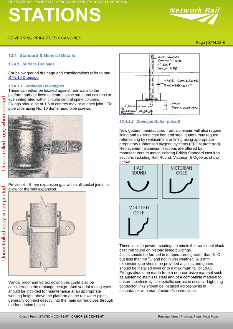
13.4.1.1 Drainage Downpipes These can either be located against rear walls to the platform and / or fixed to central spine structural columns or even integrated within circular central spine columns. Fixings should be at 1.5 m centres max or at each joint. Fix pipe clips using No. 10 dome head pipe screws.
Provide 4 – 5 mm expansion gap within all socket joints to allow for thermal expansion.
Vandal proof and vortex downpipes could also be considered in the drainage design. Anti vandal roding eyes should be included for maintenance at an appropriate working height above the platform as the rainwater pipes generally connect directly into the main carrier pipes through the foundation bases.
13.4.1.2 Drainage Gutter (Lined)
New gutters manufactured from aluminium will also require lining and existing cast iron and steel gutters may require refurbishing by replacement or lining using appropriate proprietary rubberised plygene systems (EPDM preferred). Replacement aluminium sections are offered by manufacturers to match existing British Standard cast iron sections including Half Round, Victorian & Ogee as shown below.
These include powder coatings to mimic the traditional black cast iron found on historic listed buildings. Joints should be formed in temperatures greater than 5 oC but less than 40 oC and not in wet weather. A 3 mm expansion gap should be provided at joints and gutters should be installed level or to a maximum fall of 1:600. Fixings should be made from a non-corrosive material such as austenitic stainless steel and of a compatible material to ensure no electrolytic bimetallic corrosion occurs. Lightning conductor links should be installed across joints in accordance with manufacturer’s instructions.
Close | Print | STATION CONTENT | CANOPIES CONTENT Previous View | Previous Page | Next Page

OPERATIONAL PROPERTY DESIGN AND CONSTRUCTION HANDBOOK
STATIONS GOVERNING PRINCIPLES > CANOPIES
Page | STN:13-9
Close | Print | STATION CONTENT | CANOPIES CONTENT Previous View | Previous Page | Next Page
Network Rail
13.4.1.3 Drainage Gutter (unlined)
ar
k ound Victorian
gee) found on historic listed buildings.
Corrosion resistant seamless aluminium guttering finished with a polyester powder coating will provide a durable, weresistant, colourfast finish which will offer significant cost savings over other materials such as uPVC, cast iron and steel that require regular maintenance and painting giving the guttering a life expectancy of 35 to 50 years. As it has seamless joints, and potential leakage, can be avoided in lengths up to 35 m. Replacement aluminium sections are available from manufacturers to match the traditional blaccast iron British Standard sections (Half R
Fascia brackets should be at 915 mm centres directly fixed through uPVC fascia boarding’s to a timber sub-frame using 32 mm long No. 10 screws roundhead screws. Rise and fall brackets bonded into masonry mortar beds can also be used when fixing to masonry walls.
O
New valley and parapet gutters may require underlining to maintain the required insulation and thermal characteristics of the roof and not form a thermal break. This can be done by installing proprietary gutter profiles from such as Wards that come complete with insulation attached as shown in the detail below: -

OPERATIONAL PROPERTY DESIGN AND CONSTRUCTION HANDBOOK
STATIONS GOVERNING PRINCIPLES > CANOPIES
Page | STN:13-10
Network Rail
13.4.1.4 Valley and Parapet Gutters: Proprietary extruded aluminium sections can be installed. Width and depth of section will depend on discharge rating required. Width of valley gutters may be dependant upon maintenance access requirements. As such gutters can be designed to act as a permanent access walkway in accordance with BS EN 12056 – valley gutters to be 600 mm wide minimum and parapet gutters to be 300 mm minimum wide. Both sides of valley gutters should have the same slope.
13.4.1.5 Drainage Hopper: Proprietary aluminium hopper heads are used to channel gutters into downpipes and certain manufacturers have also developed replacement aluminium sections to match the traditional black cast iron British Standard sections found on historic listed buildings. Copper hopper heads are also readily available for conservation works:
Hoppers are also used in underground drainage to collect rainwater. These are generally an integral part of trapped and untrapped gullies used at building perimeters. They can receive both horizontal inlet pipes and vertical rainwater pipes and has removable grates for rodding:
13.4.2 External Joinery Details
13.4.2.1 External Fascia Board: These can comprise proprietary uPVC panels fixed to a timber sub-frame or fixed using self tapping self drilling screw fixings to hot or cold rolled secondary trimmer steelwork. On existing structures the fascia boards are more likely to comprise timber and as such repairing and replacing to match the existing with readily available softwoods may have limited maintenance life. A more economic approach may be to remove the existing timber system and replace with more durable modern uPVC units.
Close | Print | STATION CONTENT | CANOPIES CONTENT Previous View | Previous Page | Next Page
OPERATIONAL PROPERTY DESIGN AND CONSTRUCTION HANDBOOK
STATIONS GOVERNING PRINCIPLES > CANOPIES
Page | STN:13-11
Network Rail
13.4.2.2 External Soffit or Ceiling Boarding It is envisaged that any soffit or ceiling boarding located externally under or on the canopy will comprise uPVC panels suitably fixed in accordance with the manufacturers instructions to either a timber or a hot or cold rolled steelwork support sub-frame.
13.4.2.3 External Valence These can comprise uPVC proprietary units with fretwork to match traditional patterns. On existing structures repairing or replacing existing timber units with new softwood sections may have limited maintenance life. A more appropriate solution may be to replace the existing timber system with a more durable uPVC system. With new canopies proprietary cladding systems can be used to create aerodynamic shape effects using curved eaves details such as illustrated below:
13.4.3 Maintenance, Access & Safety Equipment
13.4.3.1 Access (Horizontal): Horizontal access should be provided to facilitate the safe maintenance and cleaning of such items as canopy glazing and drainage. Suitable proprietary lightweight GRP units such as those manufactured by 'Latchways' can be installed on the roof supported off the primary steelwork structure. ‘Mansafe’ systems (refer to 1.1.4.3.3) can also be used against unguarded walkways.
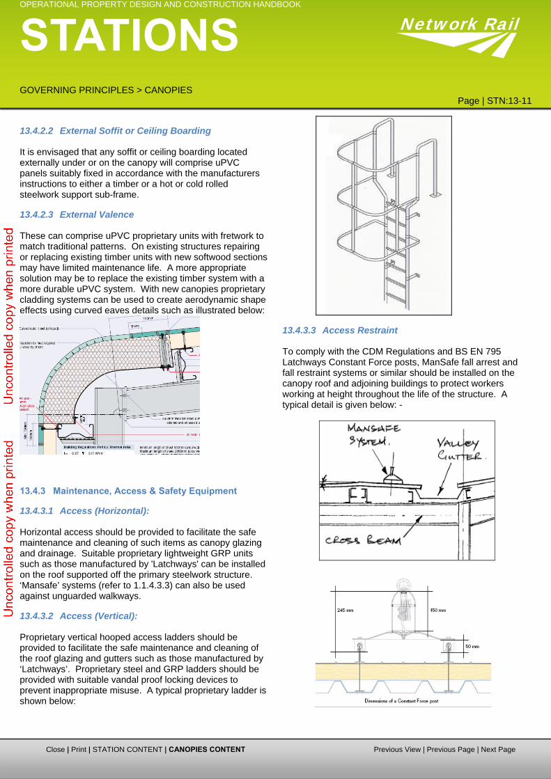
13.4.3.2 Access (Vertical): Proprietary vertical hooped access ladders should be provided to facilitate the safe maintenance and cleaning of the roof glazing and gutters such as those manufactured by ‘Latchways’. Proprietary steel and GRP ladders should be provided with suitable vandal proof locking devices to prevent inappropriate misuse. A typical proprietary ladder is shown below:
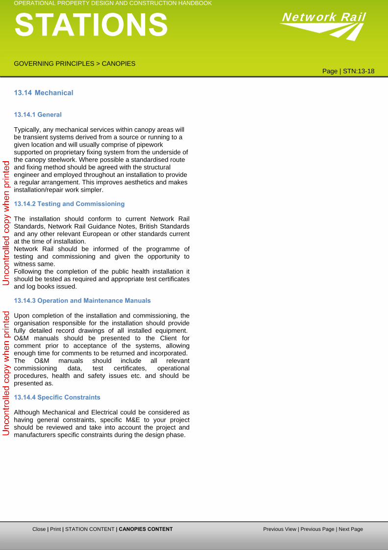
13.4.3.3 Access Restraint To comply with the CDM Regulations and BS EN 795 Latchways Constant Force posts, ManSafe fall arrest and fall restraint systems or similar should be installed on the canopy roof and adjoining buildings to protect workers working at height throughout the life of the structure. A typical detail is given below: -
Close | Print | STATION CONTENT | CANOPIES CONTENT Previous View | Previous Page | Next Page

OPERATIONAL PROPERTY DESIGN AND CONSTRUCTION HANDBOOK
STATIONS GOVERNING PRINCIPLES > CANOPIES
Page | STN:13-12
Network Rail
13.4.4 Structural
13.4.4.1 Beams, Girders, Joists & Purlins Beams and girders to canopies may comprise steel proprietary sections. Girders may be fabricated from steel plates welded together to suit specific loading, bending, deflection and shear arrangements. Girders are typically primary members designed to support beams and joists. Lattice girders are made from small diagonal members arranged in a chequer grid at close centres typically sandwiched between doubled up member top and bottom chords. Joists may be of either steel I section or timber rectangular section designed to support floor and roof systems in either steel to BS EN 10025-2 S275/355JR and BS EN 10210-1 S275/S355JOH, concrete or timber. Purlins are either in timber or steel at close centres and support the roof coverings to the canopy. In new canopy design proprietary Kingspan cold rolled C and Z profiles are used. In refurbishment projects CHS channel sections or RHS/SHS box sections may be the most appropriate choice. For canopies the use of CHS and SHS sections may lend themselves to achieving elegant structures but at a financial premium. UC columns and UB cross beams with tapered cantilever T-section rafters may provide the most economical and practical solution.
13.4.4.2 Deck or Floor: Decks typically provide the horizontal load supporting surface of bridges (and footbridges) supported by beams, girders, joists and trusses. Floors typically are suspended and can comprise of either Bison pre-cast units or in-situ concrete on permanent steel shuttering on steel beams or
in-situ concrete slab with integral concrete beams or timber joists with tongue and groove boarding or plywood decking. Ground bearing floors traditionally comprise in-situ reinforced concrete.
13.4.4.3 Space Frames: Typically in steel these comprise multiple triangulated members in more than one plane. Steel SHS and CHS sections with welded connections spliced into manageable components bolted together on site can be designed and erected to achieve large spanning roof structures.
13.4.4.4 Lattice Trusses: These typically comprise multiple evenly triangulated diagonals configured between a top and bottom chord. Existing trusses may comprise diagonal mild steel flats or angles riveted between chords made from back to back angles. Larger spanning trusses may include chords comprising back to back channel sections. New modern trusses may comprise CHS, RHS and SHS sections welded together and splices into components for transportation and erection on site.
13.4.4.5 Cantilever Support: This is typically a steel, timber or concrete beam or column member fully fixed at one end with or without a restraint mechanism at its other free end. Typically canopies are designed as free standing structures and the columns designed to cantilever against the forces of nature such as wind and the passing pressures generated by trains. Little or no support is often relied upon from adjoining existing load bearing masonry station booking office and waiting rooms.
13.4.4.6 Columns These members are either in steel, concrete or timber and span vertically to take vertical loads acting along the principal axis of the member. For canopy structures steel SHS Box sections are more elegant, but UC sections are more economical and lend themselves to simpler and cheaper connections. Rainwater down pipes can also be concealed and protected by the flanges when fixed to the column webs.
13.4.4.7 Architectural Glazing: Architectural glazing typically comprises polyester powder coated extruded aluminium alloy glazing bars to BS 1474 at 600 mm centres supporting 7 mm wire cast patent glazing or hermetically sealed double glazed units with 6 mm thick float, laminated or toughened glass designed and detailed to BS 5516. Glazing panels typically fixed to purlins using sliding shoes and saddles and zinc plated self drilling, self
Close | Print | STATION CONTENT | CANOPIES CONTENT Previous View | Previous Page | Next Page

OPERATIONAL PROPERTY DESIGN AND CONSTRUCTION HANDBOOK
STATIONS GOVERNING PRINCIPLES > CANOPIES
Page | STN:13-13
Network Rail
tapping screws with appropriate bimetallic strips to prevent electrolytic corrosion. A typical powder coater extruded aluminium alloy section 6063-T6 to BS1474 for single glazing by Lonsdale from the Skyguard series is shown below:
The following detail illustrates how the glazing bars are connected to the hot rolled steel channel purlin sections using riveted fixing shoes screwed to the channels using self drilling self tapping proprietary Ejot or TEK screws:
13.4.4.8 Cladding: Proprietary sandwich cladding panels such as Kingspan KS1000 supported off purlins can be used to provide a waterproof covering to non-glazed canopy roofs. The cladding should be made watertight with aluminium or lead sheeting lapped under the cladding panels and dressed up abutting vertical faces as shown in the example below:
13.4.4.9 Foundations: Canopy foundations to vertical cantilever columns should be designed to resist the bending moments and shear forces generated by the forces acting on the canopy structure. Foundations should be designed to suit the ground
conditions encountered and can comprise either reinforced concrete pad foundations, reinforced concrete pile caps supported on continuous flight auger reinforced concrete piles. Rainwater downpipe and drainage channel connections may be cast integral with the concrete footings. Concrete grades should be specified in accordance with BS EN 206 and should take cognisance of soil chloride and sulphate concentrations and exposure conditions. Reference should be made to the Geotechnical Site Investigation interpretative reports in determining the soil classification. Holding down bolts and boxes should be supplied by the steelwork fabricator for inclusion in the foundation construction works by the main contractor. A typical holding down bolt arrangement is illustrated below:
All steelwork below platform finishes should be encased in a 100 mm minimum thickness of lean mix concrete to prevent corrosion. The temporary works required during the excavation of such footings on existing platforms should pay particular attention to the structural stability of the platform front wall and the likelihood of undermining footings to existing station building walls or retaining walls to the rear of the platform. Due cognisance of the construction sequence, platform closures and possession periods, the time required to complete the foundation works, the safe distances of site hoardings from the platform edge and any temporary reinstatements should be considered at an early stage in the canopy foundation design. The inclusion and assessment of existing cast iron columns in the new canopy design is a most desirable solution provided that necessary investigations and repairs are undertaken to the columns to achieve the desired design life before requiring further maintenance.
Close | Print | STATION CONTENT | CANOPIES CONTENT Previous View | Previous Page | Next Page

OPERATIONAL PROPERTY DESIGN AND CONSTRUCTION HANDBOOK
STATIONS GOVERNING PRINCIPLES > CANOPIES
Page | STN:13-14
Network Rail
13.4.4.10 Typical Details and Examples The following drawings show typical details and examples of canopy structures used on past NWR projects. Whilst not necessarily providing comprehensive details for all situations, where possible these details should be used for new and replacement structures subject to compliance with planning, listed building consents etc.
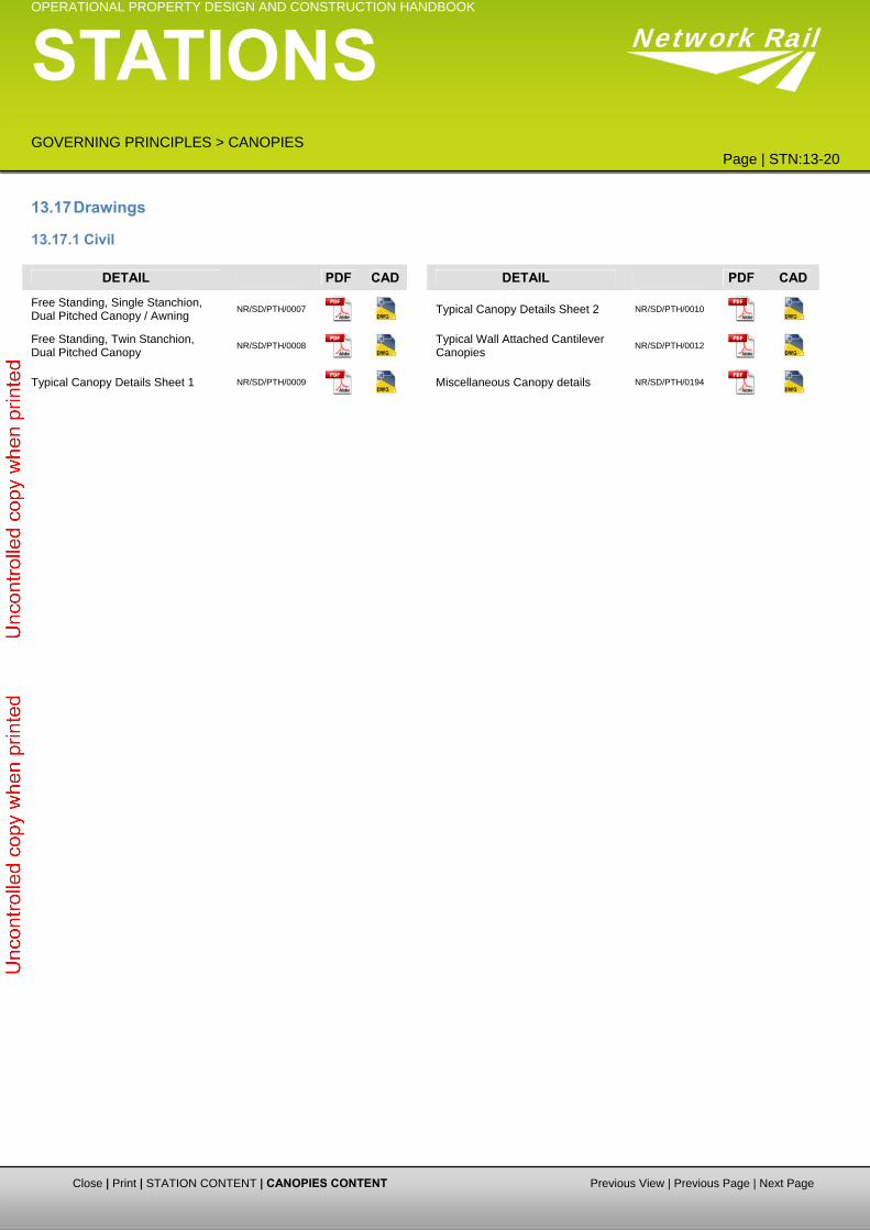
NR/SD/PTH/0007 - Free Standing, Single Stanchion, Dual
Pitched Canopy / Awning NR/SD/PTH/0008 - Free Standing, Twin Stanchion, Dual
Pitched Canopy NR/SD/PTH/0009 - Typical Canopy Details Sheet 1 NR/SD/PTH/0010 - Typical Canopy Details Sheet 2 NR/SD/PTH/0012 - Typical Wall Attached Cantilever
Canopies NR/SD/PTH/0194 – Miscellaneous Canopy Details # Space available for Further Development
Close | Print | STATION CONTENT | CANOPIES CONTENT Previous View | Previous Page | Next Page

OPERATIONAL PROPERTY DESIGN AND CONSTRUCTION HANDBOOK
STATIONS GOVERNING PRINCIPLES > CANOPIES
Page | STN:13-15
Network Rail
13.5 M&E DESIGN PRINCIPLES & CONSTRAINTS
13.5.1 General Canopies generally should be part of the platform installation and as such reference should be made to the ‘Platform’ section of this document regarding the electrical installation.
13.6 Lighting and Emergency Lighting
13.6.1 Columns Columns are not generally required to canopies due to the height limitations and the availability of suspension points for luminaires from the canopy structure.
13.6.2 Luminaires Luminaires should utilise the most cost effective control gear in terms of energy usage, effects on lamp life and capital costs. Control gear should be power factor corrected to 0.95 or better. HID control gear should be fitted with thermal cut-outs or timed ignitors. The control gear used with fluorescent lamps should be capable of starting the lamps at an ambient temperature down to -10oC. Luminaires used for station canopies should provide sufficient illumination to enable safe use by both the public and staff during the hours of darkness and low light conditions, be suitable for the railway environment and be simple to maintain given the limited time available for access and the proximity of the general public. Enclosed luminaires should be used for canopy lighting, with a minimum rating of IP54 to ensure minimal build up of internal dirt. IP65 or better is preferred. Luminaires generally should have a ‘white light’ aspect, as that produced using Philips CosmoPolis or Venture Whitelux lamps, unless they are required to match existing luminaires, as a mixing of light colours should be avoided. Low pressure sodium (SOX), high pressure mercury (MBF) and tungsten halogen lamps should not be used. All luminaires should conform to the product standard EN60598-1 and be CE marked. Surface or suspended luminaires, as approved by Network Rail, should be used and should be fixed to the canopy structure using proprietary fixings. Circuit wiring should be XLPE/SWA/LSF or LSF singles cables and should terminate at a point of local isolation using either IP 54 plug and socket arrangement or IP 54 rated switched fused spur with final connections to each luminaire using multicore OHLS flex. Luminaires should be mounted within the ‘Green Zone’ if possible with all maintenance being able to be undertaken away from the platform edge. On some canopies it may be aesthetically pleasing to have some backlight to illuminate the internal roof area and luminaires should be selected to provide this illumination.
Where buildings abut the platform consideration should be given to the feasibility of using building mounted luminaires to provide or enhance the general illumination. Emergency lighting should be provided, as BS 5266, by the use of auxiliary lamps fed from a central battery system, integral battery and charging units, or stand alone bulkhead and/or twin spot fittings to illuminate escape routes. Where required, to conform to BS5266 and Network Rail Group Standards, emergency lighting should be installed. This should preferably be integral to the luminaire either by the use of auxiliary lamps fed from a central battery system or integral battery and charging units. Stand alone bulkhead and/or twin spot fittings should only be used if no alternative can be provided. Emergency exit signs should be 3 hour maintained vandal proof luminaire complete with T5 lamps, high frequency control gear and euro legend indicating the exit direction. A minimum of 2 No circuits should be used (different phases where possible) with luminaires being connected alternately to separate circuits so that in the event of a circuit or phase failing alternate luminaires should remain lit. Generally the lighting level over the useable platform edge should not be less than 10 lux at platform level and on DOO stations should be a minimum of 20lux at platform level along the extent of the platform length to which DOO applies. The horizontal uniformity should not be less than 0.4. The mandatory requirements for the design of platform lighting is set out in Network Rail document GI/RT 7016 and reference should also be made to this document and all other relevant documents including but not limited to Network Rail document General Guidance of the Lighting of Railway Premises GI/GN 7520 and CIBSE Lighting Guide LG1 and LG3. When designing the lighting for canopies the designer should take account of the deterioration in lighting level over time in order to retain minimum lighting levels. Luminaires should be positioned so as not to conflict with signalling either by obstruction, being mistaken for a signal, overpowering a signal or by reflection or refraction. Consideration should be given to the location of luminaires so as not to conflict with the CCTV layout and should not be mounted directly in front of CCTV cameras. On DOO stations luminaires should be positioned so not to impair the view of the driver or staff by glare, reflection or affecting the view of DOO cameras.
13.6.3 Lighting Control The canopy lighting should normally be controlled by use of photocell (dusk to dawn) and time clock controlling contactors. The photocell should operate the platform luminaires when the natural light reaches a predetermined
Close | Print | STATION CONTENT | CANOPIES CONTENT Previous View | Previous Page | Next Page

OPERATIONAL PROPERTY DESIGN AND CONSTRUCTION HANDBOOK
STATIONS GOVERNING PRINCIPLES > CANOPIES
Page | STN:13-16
Network Rail
level and the time clock should ensure that the lights normally only operate between a predetermined period before the first train arrives and a predetermined period after the last train departs. Standard din rail mounted contactors should be mounted in a loose enclosure of adequate size alongside a 24hour/7day din rail mounted timeclock of the same manufacturer. A light sensitive switch should be installed with the photocell mounted on a north facing aspect and the control unit within the loose enclosure. An override switch should be provided for maintenance purposes and for use if the control circuit fails. On some stations it may be necessary to leave a number of luminaries’ permanently lit during the hours of darkness for security purposes and this should be qualified with the TOC and Network Rail. On small stations with no buildings the controls should be located within the main cubicle alongside the distribution board. On stations with the supply located within a building the controls should be mounted either within the building or dedicated cabinets/feeder pillars on the respective platforms.
13.7 Small Power
13.7.1 Accessories Canopies generally should be part of the platform installation and as such reference should be made to the ‘Platform’ section of this document regarding the installation of small power and supplies to equipment.
13.8 Fire Alarm
13.8.1 Equipment Open sided canopies generally do not require the installation of a fire detection system and should be part of the platform installation and as such reference should be made to the ‘Platform’ section of this document regarding the installation of a fire alarm. A fully enclosed station canopy is slightly different in that consideration must be given to raising an alarm in the event of an emergency such as for fire. This can be done by use of PAVA system or fire alarm system where installed. Review of the fire strategy for a facility, risk assessment, evacuation procedures and discussion with Network Rail Fire Engineering staff will need to be undertaken to allow an appropriate assessment of each location to be completed, that will inform as to whether an alarm system is required.
13.9 Ancillary Services
13.9.1 General Canopies generally should be part of the platform installation and as such reference should be made to the ‘Platform’ section of this document regarding the installation of PA, CIS, CCTV and help points.
13.10 Cables and Containment Canopies generally should be part of the platform installation and as such reference should be made to the ‘Platform’ section of this document regarding the installation of cables and containment All cables should have copper conductors, comply with British standards and preferably be made in Britain. Cables generally should be of the following types:- LSF insulated and sheathed single or multicore with
steel wire armour with circular or sectional conductors, 600/1000v grade to BS6724. (XLPE/SWA/LSF)
LSF insulated stranded single core to BS6004 (LSF singles)
Mineral insulated copper clad with or without LSF sheath 600v grade to BS6207 (MICC)
Soft skin fire rated and enhanced zero halogen and low smoke cables to BS 7629-1
Circular form flexible multicore cables 300/500v grade to BS6500
Reduced cross section neutral conductors and twin and earth cables should not be used. All cable installations should be as neat and unobtrusive as possible with containment that integrates with the fabric of the building and in public areas is vandal resistant. Containment within voids or surface mounted should utilise proprietary fixings. All steel containment should be hot dipped galvanised steel and be powder coated if required. PVC trunking and/or conduit should not be used. Cables should generally be XLPE/SWA/LSF and LSF singles and where used to supply essential equipment should be fire rated. Generally XLPE/SWA/LSF cables within the canopy should be contained on hot dipped galvanised steel medium duty return flange cable tray and LSF singles and multicore flex should be contained using hot dipped galvanised steel trunking and conduit. All containment should be of a suitable size to accommodate all cables that are to be run within and through the canopy. Where public have access to the cable tray it should be covered with the appropriate size hot dipped galvanised steel lid secured using proprietary fixings. Manufactured bends should be used for all changes of direction for the cable tray and trunking and conduit boxes and/or proprietary bender should be used for all changes of direction for conduit. Inspection bends should not be used in conduit. IP 56 Stainless steel
Close | Print | STATION CONTENT | CANOPIES CONTENT Previous View | Previous Page | Next Page

OPERATIONAL PROPERTY DESIGN AND CONSTRUCTION HANDBOOK
STATIONS GOVERNING PRINCIPLES > CANOPIES
Page | STN:13-17
Network Rail
flexible conduit should be used to protect the cable for final connection from the isolator to the equipment. All containment should be run at high level within the canopy structure if possible or on an adjoining wall and/or trapeze bracket arrangement supported from the canopy structure. Stainless steel cable ties or fire rated cleats should be used to secure cables to cable tray. LV circuits and ELV circuits should be run in or on separate containment. IP 56 Stainless steel flexible conduit should be used to protect the cable for final connection from the isolator to the equipment. All cables should be labelled with the circuit reference at both the supply and load ends, at 10m intervals, where they pass through ducts and at both sides where they pass through a wall. Cables should be segregated as required by BS7671 with LV and ELV cables normally being run in separate containment. All new containment should be integrated into the existing containment to ensure continuity of containment.
13.11 Earthing and Lightning Protection All earthing should comply with BS7671 and Network Rail Group Standards and Guidance Notes. Lightning protection should comply with BS EN 62305 and a risk assessment should be carried out to determine the necessity for lightning protection and surge suppression. If required, the lightning protection system should be designed and installed by a specialist contractor and should consist of an air termination network connected to down tapes and the building structural steelwork and terminate at accessible earth pits provided around the perimeter of the building. Surge suppression should be considered and be installed, if required, to all external electrical services at risk. On stations where there is an AC overhead traction line a dual link main earth bar should be installed at the main incoming position with the DNO earth connected to one removable link and a 158mm sq Aluminium stranded traction bond (installed by others) to the second removable link. A minimum 16mm CPC should be provided for all sub mains and installed to all distribution board main earth bars from the main earth bar and all external electrical accessories should be connected to the main earth bar of the supply distribution board with a minimum CPC of 16mm sq. In areas where there is DC traction electrification, there should be no electrical connection between the DC system and the station electrical installation. Stray earth collectors should be installed by others.
13.12 Testing and Commissioning The installation should conform to all current British and European standards (in particular BS 7671 IEE Wiring Regulations) and current Network Rail Group Standards and Guidance Notes that are applicable to and at the time of the installation. Network Rail should be informed of the programme of testing and commissioning and given the opportunity to witness same. Following the completion of the electrical installation it should be tested as detailed within BS 7671 and appropriate test certificates and log books issued.
13.13 O&M Manuals Upon completion of the installation and commissioning, the organisation responsible for the installation should provide fully detailed record drawings of all installed equipment, commissioning and test certificates. O&M manuals should be presented to the Client for comment prior to acceptance of the systems, allowing enough time for comments to be returned and incorporated. The O&M manuals should include all relevant commissioning data, test sheets, log books, operational procedures, health and safety issues etc. and should be presented as recommended within BSRIA application guide 1/87.1
Close | Print | STATION CONTENT | CANOPIES CONTENT Previous View | Previous Page | Next Page
OPERATIONAL PROPERTY DESIGN AND CONSTRUCTION HANDBOOK
STATIONS GOVERNING PRINCIPLES > CANOPIES
Page | STN:13-18
Close | Print | STATION CONTENT | CANOPIES CONTENT Previous View | Previous Page | Next Page
Network Rail
13.14 Mechanical
13.14.1 General Typically, any mechanical services within canopy areas will be transient systems derived from a source or running to a given location and will usually comprise of pipework supported on proprietary fixing system from the underside of the canopy steelwork. Where possible a standardised route and fixing method should be agreed with the structural engineer and employed throughout an installation to provide a regular arrangement. This improves aesthetics and makes installation/repair work simpler.
13.14.2 Testing and Commissioning The installation should conform to current Network Rail Standards, Network Rail Guidance Notes, British Standards and any other relevant European or other standards current at the time of installation. Network Rail should be informed of the programme of testing and commissioning and given the opportunity to witness same. Following the completion of the public health installation it should be tested as required and appropriate test certificates and log books issued.
13.14.3 Operation and Maintenance Manuals Upon completion of the installation and commissioning, the organisation responsible for the installation should provide fully detailed record drawings of all installed equipment. O&M manuals should be presented to the Client for comment prior to acceptance of the systems, allowing enough time for comments to be returned and incorporated. The O&M manuals should include all relevant commissioning data, test certificates, operational procedures, health and safety issues etc. and should be presented as.
13.14.4 Specific Constraints Although Mechanical and Electrical could be considered as having general constraints, specific M&E to your project should be reviewed and take into account the project and manufacturers specific constraints during the design phase.

OPERATIONAL PROPERTY DESIGN AND CONSTRUCTION HANDBOOK
STATIONS GOVERNING PRINCIPLES > CANOPIES
Page | STN:13-19
Network Rail
13.15 Specifications and Guidance
13.15.1 Model Clauses The following lists those sections applicable only to the requirements shown on the standard canopy construction detail drawings and to the associated maintenance details. It should be noted that that Network Rail are in the process of updating the Model Clauses.
Section Title 51 Excavations 52 Earthworks 80 Structural Concrete 85 Concrete for Ancillary Purposes 90 Steelwork 110 General requirements for
Waterproofing 113 Flexible PVC Sheet Waterproofing
System 130 General Requirements for Inspection 131 Inspection of New Steelwork 133 Inspection of Protective Treatment 134 Inspection of Waterproofing App 130A Visit Report 140 Steelwork Hot Rolled Sections 141 Steelwork Cold formed Sections 172 New Fabricated Steelwork 175 Concrete 176 Protective Treatment Tables 180 General Requirements for Drainage 181 Materials 182 Installation 186 Maintenance of Track Drainage 190 Ducts 191 Cable Troughing
13.15.2 Useful Specifications
1. 5th Edition National Structural Steelwork Specification for Building Construction
2. Debris/Pigeon Netting - Specification
3. Operational Property Cladding/Coverings/Fibre
Cement/Composite Specification
4. Operational Property Roof Tiles Specification
5. Operational Property Roof Slates Specification
6. Operational Property Flat Roofing Specification
7. Operational Property Liquid Applied Waterproof Roof Coatings Specification
8. Operational Property Leadwork Specification
9. Electrical Specification
13.15.3 Useful Guidance
1. Operational Property Design Life – Guidance Note
2. Electrical Testing and Inspection Information Policy
3. Lightning Protection Policy
4. Operational Property Engineering policy for Lightning Protection Systems for Railway Premises
5. Territory Building Engineer O&M Policy
13.16 Product Data Section provided for future development
Close | Print | STATION CONTENT | CANOPIES CONTENT Previous View | Previous Page | Next Page
OPERATIONAL PROPERTY DESIGN AND CONSTRUCTION HANDBOOK
STATIONS GOVERNING PRINCIPLES > CANOPIES
Page | STN:13-20
Network Rail
13.17 Drawings
13.17.1 Civil
DETAIL PDF CAD DETAIL PDF CAD
Free Standing, Single Stanchion, Dual Pitched Canopy / Awning
NR/SD/PTH/0007
Typical Canopy Details Sheet 2 NR/SD/PTH/0010
Free Standing, Twin Stanchion, Dual Pitched Canopy
NR/SD/PTH/0008
Typical Wall Attached Cantilever Canopies
NR/SD/PTH/0012
Typical Canopy Details Sheet 1 NR/SD/PTH/0009
Miscellaneous Canopy details NR/SD/PTH/0194
Close | Print | STATION CONTENT | CANOPIES CONTENT Previous View | Previous Page | Next Page
OPERATIONAL PROPERTY DESIGN AND CONSTRUCTION HANDBOOK
STATIONS GOVERNING PRINCIPLES > CANOPIES
Page | STN:13-21
Network Rail
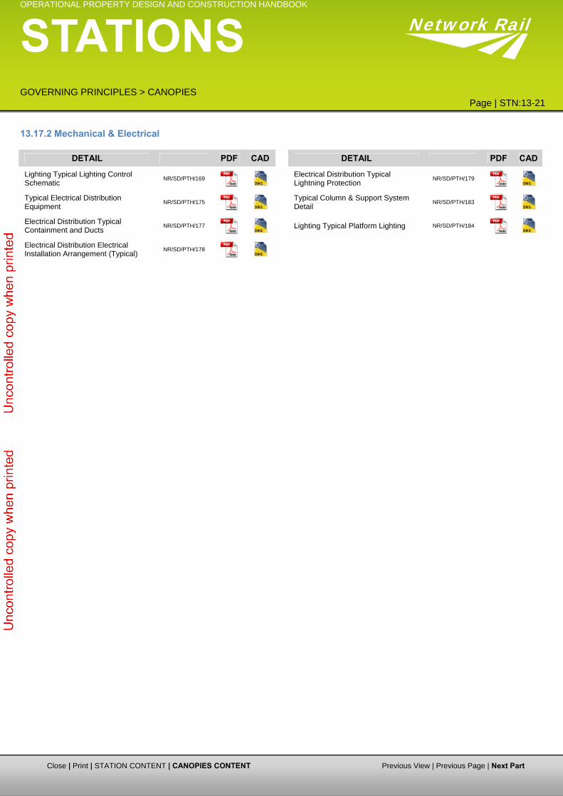
13.17.2 Mechanical & Electrical
DETAIL PDF CAD DETAIL PDF CAD
Lighting Typical Lighting Control Schematic
NR/SD/PTH/169
Electrical Distribution Typical Lightning Protection
NR/SD/PTH/179
Typical Electrical Distribution Equipment
NR/SD/PTH/175
Typical Column & Support System Detail
NR/SD/PTH/183
Electrical Distribution Typical Containment and Ducts
NR/SD/PTH/177
Lighting Typical Platform Lighting NR/SD/PTH/184
Electrical Distribution Electrical Installation Arrangement (Typical)
NR/SD/PTH/178
Close | Print | STATION CONTENT | CANOPIES CONTENT Previous View | Previous Page | Next Part