Operational Amplifiers Basic Theory & Use in Analog Signal Processing By Muhammad Bilal PhD...
40
Operational Amplifiers Basic Theory & Use in Analog Signal Processing By Muhammad Bilal PhD Candidate Department of Computer Engineering, LUMS
-
Upload
augustus-johnston -
Category
Documents
-
view
213 -
download
0
Transcript of Operational Amplifiers Basic Theory & Use in Analog Signal Processing By Muhammad Bilal PhD...

Operational AmplifiersBasic Theory
& Use in Analog Signal Processing
By
Muhammad BilalPhD Candidate
Department of Computer Engineering, LUMS

Operational Amplifiers – Brief History
• Appeared around 1947 (vacuum tube age)
• Combination of High Gain & Negative Feedback
• Miniaturization after invention of BJT
• Integrated Circuit Operational Amplifier– Robert Widlar at Fairchild Semiconductor Corps
(1968)– Industry standard, the 741
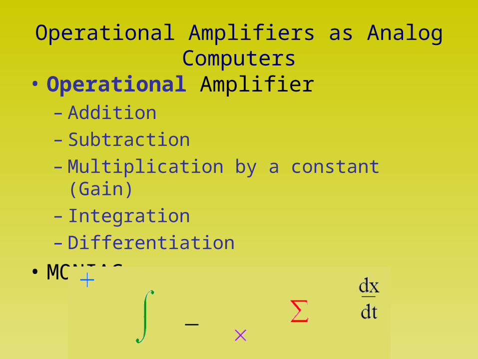
Operational Amplifiers as Analog Computers
• Operational Amplifier– Addition– Subtraction– Multiplication by a constant (Gain)– Integration– Differentiation
• MONIAC

Operational Amplifiers
Op-Amps

Schematic

Block Diagram
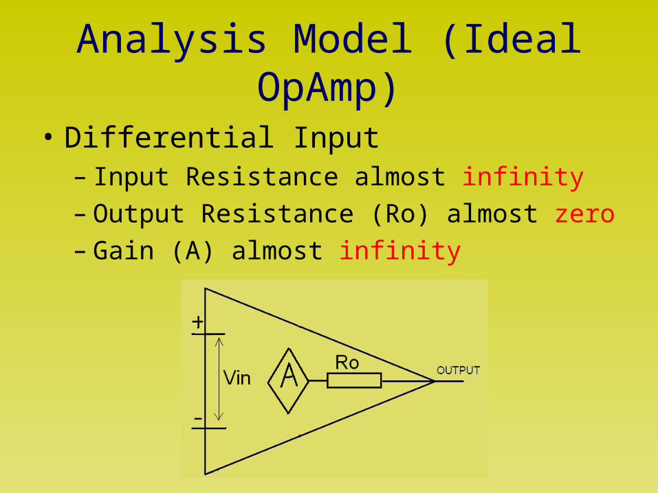
Analysis Model (Ideal OpAmp)
• Differential Input– Input Resistance almost infinity– Output Resistance (Ro) almost zero– Gain (A) almost infinity

OpAmp Configurations
• Inverting Amplifier

OpAmp Configurations-- Inverting Amplifier
)()0(
)(
noutp
inout
npin
VAVV
AAVV
VVV
• No current can flow through Vp,Vn terminals
1
2
21
21
21
R
R
V
V
R
VA
V
RA
VV
R
VV
R
VV
ii
in
out
outoutout
in
outnnin
RR

OpAmp Configurations-- Inverting Amplifier
Lessons from Inverting Amp. configuration
• Gain is set via external components– Stable gain due to ratio of resistors
• Effects of extremely high gain
– Virtual short circuit (Vp = Vn)– Negative Feedback compensates for the
internal high gain of OpAmp

OpAmp Configurations– Non-Inverting Amplifier
Gain = 1 + R2 / R1

OpAmp Configurations– Voltage Follower
Due to negative feedback, virtual short will occur, forcing Vn to be equal to Vp which is in turn equal to Vs. Thus Vout = Vs and hence the name voltage follower.

OpAmp Configurations-- Inverting Amplifier
• Generic
• Gain = - Z2 / Z1
f
RZ
LjZ
CjZ
sistor
Inductor
Capacitor
2
1
Re

OpAmp Configurations-- Integrator
RC
j
jV
jV
in
out
)(
)(
0 10 20 30 40 50 60 70 80 90 1000
1
2
3
4
5
6
7
8
9
10Frequency Response of "Integrator"
Frequency
Mag
nitu
de
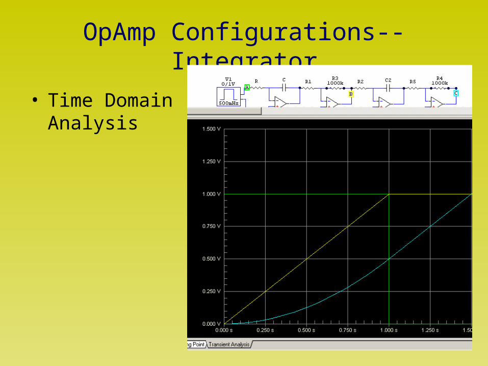
OpAmp Configurations-- Integrator
• Time Domain Analysis

OpAmp Configurations-- Differentiator
RCjjV
jV
in
out
)(
)(
0 10 20 30 40 50 60 70 80 90 1000
1
2
3
4
5
6
7
8
9
10Frequency Response of "Differentiator"
Frequency
Mag
nitu
de

OpAmp Configurations-- Differentiator
• Time Domain Analysis

OpAmp Configurations-- Filters
• Integrator– First Order Low Pass Filter– Extremely high gain at low frequencies
• Only used within a closed loop
• Differentiator– First Order High Pass Filter

OpAmp Circuits– Frequency Counter
• A ‘Differentiator’ followed by ‘Peak Detector’

OpAmp Circuits– Summer
Vout = -(Vs2 + Vs1) (R1=R2=R3)

OpAmp Circuits– Summer
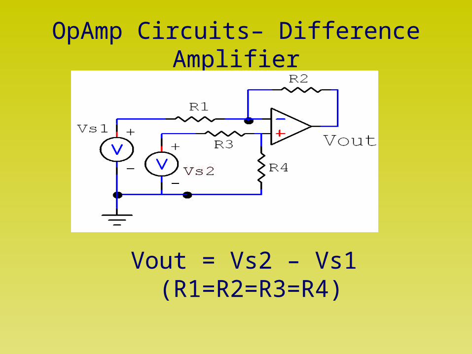
OpAmp Circuits– Difference Amplifier
Vout = Vs2 – Vs1 (R1=R2=R3=R4)

OpAmp Circuits– Current Amplifiers
• V to V
• V to I
• I to V
• I to I
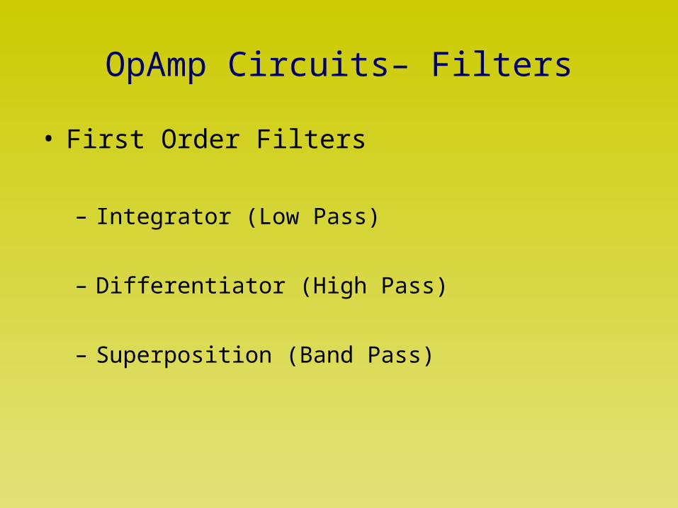
OpAmp Circuits– Filters
• First Order Filters
– Integrator (Low Pass)
– Differentiator (High Pass)
– Superposition (Band Pass)

OpAmp Circuits– Filters
•First Order Low Pass Filter
CRjR
R
jV
jV
in
out
21
2
1
1
)(
)(

OpAmp Circuits– Filters
•Second Order Low Pass Filter

OpAmp Non-linear Circuits
• Voltage Comparators
• Schmitt Trigger– Variable Threshold

OpAmp Non-linear Circuits
• Superdiode– Another manifestation of ‘virtual short’ due to
negative feedback

OpAmp Non-linear Circuits
• Signal Generators– Multivibrator
• Square wave to Triangular wave conversion– Integrator

OpAmp—Solution of Differential Equations
• Real time
• Precise
• Applicable to any order
• Constant Coefficient DE’s only

OpAmp—Solution of Differential Equations
• First Order Constant Coefficient DE
)(tfbxdt
dxa

OpAmp—Solution of Differential Equations
• First Order Constant Coefficient DE• R-C circuit simulation
ta
b
Aetx
tfbxdt
dxa
)(
)(

OpAmp—Solution of Differential Equations
• Second Order Constant Coefficient DE• R-L-C circuit simulation
))sin()cos(()(
)(2
2
tBtAetx
tfcxdt
dxb
dt
xda
at

OpAmp—Solution of Differential Equations
• Second Order DE simulation
– Hardware Simulation of R-L-C circuit without actual use of Inductor
– Implementation of precise mathematical relationships given by DE’s

Analog Signal Processing
• Pros– Inherently Analog World– Precision– Simplicity– Intuitive Designs vs ‘Programming’
• Cons– Non-linearity– Rigidity– Noise Floor– Temperature dependence

Practical OpAmps Limitations
• Gain-Bandwidth Product
• Common Mode Rejection
• Slew Rate
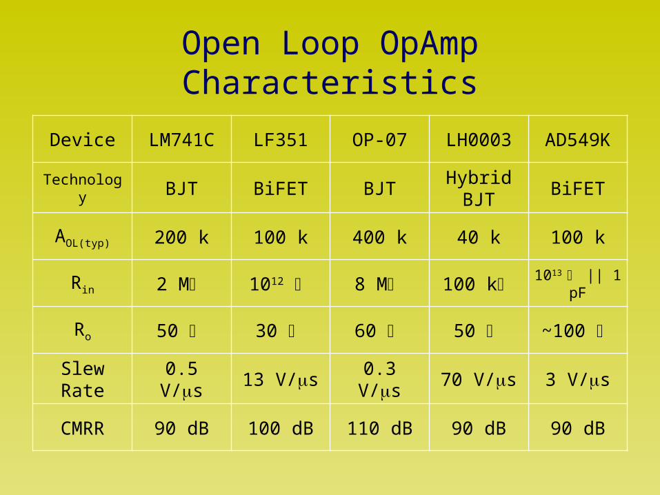
Open Loop OpAmp Characteristics
Device LM741C LF351 OP-07 LH0003 AD549K
Technology BJT BiFET BJTHybrid
BJTBiFET
AOL(typ) 200 k 100 k 400 k 40 k 100 k
Rin 2 M 1012 8 M 100 k 1013 || 1 pF
Ro 50 30 60 50 ~100
Slew Rate 0.5 V/s 13 V/s 0.3 V/s 70 V/s 3 V/s
CMRR 90 dB 100 dB 110 dB 90 dB 90 dB
References
• Design with Operational Amplifiers and Analog Integrated Circuits,Sergio Franco, 3rd Edition.
• Basic Engineering Circuit Analysis, David Irwin, 8th Edition.• Electronic Devices and Circuit Theory, Robert Boylsted, 9th Edition.

?