OPERATION MANUAL - Omron€¦ · 11.3 WIRING EXAMPLES G9SR-AD - UNIT WITH INPUT LOOP AND OUTPUT...
106
ZX-T Series Cat. No. J12E-EN-04 G9SR Safety Relays OPERATION MANUAL G9SR-BC@-@ G9SR-AD@-@ G9SR-EX@-@-@
Transcript of OPERATION MANUAL - Omron€¦ · 11.3 WIRING EXAMPLES G9SR-AD - UNIT WITH INPUT LOOP AND OUTPUT...

ZX-T Series
Cat. No. J12E-EN-04
G9SR Safety Relays
OPERATION MANUAL
G9SR-BC@-@ G9SR-AD@-@ G9SR-EX@-@-@
Operation manual G9SR
II
ORIGINAL VERSION UPDATED May 19, 2014 REVISION 2 UPDATED October 07, 2014 REVISION 3 UPDATED March 30, 2016
OMRON, 2014 All rights reserved. No part of this publication may be reproduced, stored in a retrieval system, or transmitted, in any form, or by any means, mechanical, electronic, photocopying, recording, or otherwise, without the prior written permission of OMRON. No patent liability is assumed with respect to the use of the information contained herein. Moreover, because OMRON is constantly striving to improve its high-quality products, the information contained in this manual is subject to change without notice. Every precaution has been taken in the preparation of this manual. Nevertheless, OMRON assumes no responsibility for errors or omissions. Neither is any liability assumed for damages resulting from the use of the information contained in this publication.

Operation manual G9SR
III
G9SR Safety Relays: G9SR-BC-
G9SR-AD- G9SR-EX-T90- Operation Manual
Revised March 2016

Operation manual G9SR
IV
TABLE OF CONTENTS Introduction
Manual Configuration……………………………………………….….. vii Safety Precautions………………………………………………………. xi Precautions for Safe Use…………………………………………….... xviii Regulations and Standards……………………………………………. xxii Glossary, Definitions, Abbreviations………………….……………… xxv
1 PRODUCT FAMILY – GENERAL INFORMATION ..................... 1 1.1 INTENDED USE ..................................................................................................... 1 1.2 FAMILY OVERVIEW ............................................................................................. 1
1.2.1 G9SR-BC ............................................................................................................. 1 1.2.2 G9SR-AD ............................................................................................................. 2 1.2.3 G9SR-EX .............................................................................................................. 2
1.3 MECHANICAL DIMENSIONS ................................................................................... 3 2 INSTALLATION AND CONFIGURATION ................................... 4
2.1 STEP 1: INSTALLATION ENVIRONMENT ................................................................... 4 2.2 STEP 2: MECHANICAL INSTALLATION .................................................................... 4 2.3 STEP 3: ELECTRICAL INSTALLATION ...................................................................... 5
2.3.1 Install fuses for G9SR units ................................................................................. 5 2.3.2 Install fuses for output relays .............................................................................. 5 2.3.3 Install Power Supply ........................................................................................... 5 2.3.4 G9SR-BC□-□ solid state output .......................................................................... 6
2.4 STEP 4: CONFIGURE THE G9SR UNITS .................................................................... 6 2.5 STEP 5: TEST THE INSTALLATION ........................................................................... 6
3 TEST ............................................................................................... 7 3.1 TEST THE OFF BEHAVIOUR ................................................................................. 8 3.2 TEST THE ON BEHAVIOUR ................................................................................... 9
4 TECHNICAL SPECIFICATIONS ................................................. 10 4.1 GENERAL SPECIFICATIONS .................................................................................. 10 4.2 DERATING CURVE OF RELAY CONTACT CURRENT .................................................. 12 4.3 TEST PATTERN FOR OSSD TESTING ..................................................................... 13 4.4 TEST PATTERN FOR DYNAMIC INPUT TESTING ...................................................... 13
5 RESTART MODES ....................................................................... 14 5.1 MANUAL RESTART ............................................................................................ 14 5.2 WIRING EXAMPLES MANUAL RESTART ................................................................ 15
5.2.1 Manual Restart with dynamic input testing ...................................................... 16 5.2.2 Manual Restart without dynamic input testing ................................................. 16
5.3 AUTOMATIC RESTART ........................................................................................ 17 5.4 WIRING EXAMPLES AUTOMATIC RESTART ........................................................... 17
5.4.1 Automatic Restart with dynamic input testing .................................................. 18 5.4.2 Automatic Restart without dynamic input testing ............................................. 18
Operation manual G9SR
V
6 G9SR UNIT: G9SR-BC□-□ ............................................................ 19 6.1 INTRODUCTION .................................................................................................. 19 6.2 INTERNAL CONNECTIONS OF G9SR-BC□-□ .......................................................... 19 6.3 DIP SWITCHES AND FUNCTIONS OF G9SR-BC□-□.................................................. 20 6.4 LEDS OF THE G9SR-BC□-□ ............................................................................... 21
6.4.1 POWER LED = POWER ................................................................................... 21 6.4.2 IN2 LED = Input 2 ........................................................................................... 21 6.4.3 RESTART LED = Restart .................................................................................. 21 6.4.4 EDM LED = External Device Monitoring ........................................................ 22 6.4.5 ON LED = Outputs ........................................................................................... 22 6.4.6 OFF/ERR LED = OFF & Error ....................................................................... 22
6.5 LED EXAMPLES G9SR-BC□-□ ............................................................................ 23 6.5.1 Normal operation - LEDs G9SR-BC□-□ ........................................................... 23 6.5.2 Error situations - LEDs G9SR-BC□-□ .............................................................. 24
6.6 TERMINAL AND SIGNAL NAMES G9SR-BC□-□ ...................................................... 25 7 G9SR UNIT: G9SR-AD□-□ ............................................................ 26
7.1 INTRODUCTION .................................................................................................. 26 7.2 INTERNAL CONNECTIONS OF G9SR-AD□-□ .......................................................... 26 7.3 DIP SWITCHES AND FUNCTIONS OF G9SR-AD□-□ ................................................. 27 7.4 LEDS OF THE G9SR-AD□-□ ............................................................................... 28
7.4.1 POWER LED = Power ...................................................................................... 28 7.4.2 IN1 LED = Input 1 ........................................................................................... 28 7.4.3 IN2 LED = Input 2 ........................................................................................... 28 7.4.4 RESTART LED = Restart .................................................................................. 29 7.4.5 EDM LED = External Device Monitoring ........................................................ 29 7.4.6 ON LED = Outputs ........................................................................................... 29 7.4.7 OFF/ERR LED = Error ................................................................................... 29
7.5 LED EXAMPLES G9SR-AD□-□ ........................................................................... 30 7.5.1 Normal operation - LEDs G9SR-AD□-□ .......................................................... 30 7.5.2 Error situations - LEDs G9SR-AD□-□ ............................................................. 31
7.6 TERMINAL AND SIGNAL NAMES OF THE G9SR-AD□-□ UNIT ................................... 32 8 G9SR UNIT: G9SR-EX□-T90-□ ..................................................... 33
8.1 INTRODUCTION .................................................................................................. 33 8.2 INTERNAL CONNECTIONS OF G9SR-EX□-T90-□ ................................................... 33 8.3 ROTARY SWITCH FUNCTIONS OF G9SR-EX□-T90-□ .............................................. 34
8.3.1 ON-delay ............................................................................................................ 34 8.3.2 OFF-delay ......................................................................................................... 34
8.4 LEDS OF THE G9SR-EX□-T90-□ ........................................................................ 35 8.4.1 POWER LED = Power ...................................................................................... 35 8.4.2 COM LED = Input ........................................................................................... 35 8.4.3 EDM LED = External Device Monitoring ........................................................ 35 8.4.4 ON LED = Outputs ........................................................................................... 36 8.4.5 OFF/ERR LED = Error ................................................................................... 36
8.5 LED EXAMPLES G9SR-EX□-T90-□ .................................................................... 37 8.5.1 Normal operation - LEDs G9SR-EX□-T90-□ ................................................... 37 8.5.2 Error situations - LEDs G9SR-EX□-T90-□ ...................................................... 37
8.6 TERMINAL AND SIGNAL NAMES OF THE G9SR-EX□-T90-□ .................................... 38

Operation manual G9SR
VI
9 STAND-ALONE OPERATION OF A G9SR UNIT ........................ 39 9.1 WIRING EXAMPLES STAND-ALONE G9SR-BC ....................................................... 40
9.1.1 G9SR-BC wiring with dynamic testing with EDM ............................................ 40 9.1.2 G9SR-BC wiring without dynamic testing with EDM....................................... 41 9.1.3 G9SR-BC wiring with dynamic testing without EDM....................................... 42 9.1.4 G9SR-BC wiring without dynamic testing without EDM ................................. 43
9.2 STAND-ALONE G9SR-AD ................................................................................... 44 9.2.1 G9SR-AD wiring with dynamic testing with EDM ........................................... 44 9.2.2 G9SR-AD wiring with dynamic testing without EDM ...................................... 45 9.2.3 G9SR-AD wiring without dynamic testing with EDM ...................................... 46 9.2.4 G9SR-AD wiring without dynamic testing without EDM ................................. 47
10 COMBINING G9SR UNITS .......................................................... 48 10.1 INPUT LOOP ....................................................................................................... 49 10.2 OUTPUT LOOP.................................................................................................... 50 10.3 INPUT LOOP AND OUTPUT LOOP .......................................................................... 51
11 APPENDIX A: WIRING EXAMPLES .......................................... 52 11.1 WIRING EXAMPLES G9SR-BC□-□ UNIT ............................................................... 52
11.1.1 G9SR-BC□-□ in E-stop application up to PLe ................................................. 52 11.1.2 G9SR-BC□-□ in E-Stop application up to PLd ................................................. 54 11.1.3 G9SR-BC□-□ for door interlocking up to PLe with F3S-TGR-N__C .............. 56 11.1.4 G9SR-BC□-□ for door interlocking up to PLd with F3S-TGR-N__C .............. 58 11.1.5 G9SR-BC□-□ with Safety Sensors in applications up to PLe (F3S-TGR-CL) . 60
11.2 WIRING EXAMPLES G9SR-AD□-□ UNIT ............................................................... 62 11.2.1 G9SR-AD□-□ in E-Stop application up to PLe ................................................. 62 11.2.2 G9SR-AD□-□ in E-Stop application up to PLd ................................................ 64 11.2.3 G9SR-AD□-□ with door interlocking up to PLe with F3S-TGR-N__C ............ 66 11.2.4 G9SR-AD□-□ with door interlocking up to PLd with F3S-TGR-N__C ............ 68 11.2.5 G9SR-AD□-□ with Safety Sensors in applications up to PLe ........................... 70
11.3 WIRING EXAMPLES G9SR-AD□-□ UNIT WITH INPUT LOOP AND OUTPUT LOOP ......... 72 11.3.1 Machine example ............................................................................................... 72 11.3.2 Description of the safety related control functions in this application ............ 72 11.3.3 Solution - block diagram ................................................................................... 73 14.3.4 Function settings and DIP switch settings ........................................................ 73
12 APPENDIX B: LOGGING OF TEST RESULTS ........................... 77

Operation manual G9SR
VII
INTRODUCTION Thank you for purchasing a G9SR Safety Relay. This manual contains information required to use the G9SR Safety Relay. Please thoroughly read and understand this manual before you use the G9SR Safety Relay.
Intended Audience This manual is intended for the following personnel, who must also have knowledge of electrical systems (an electrical engineer or the equivalent).
• Personnel in charge of introducing Factory Automation (FA) and safety systems into production facilities
• Personnel in charge of designing FA and safety systems • Personnel in charge of managing FA facilities • Personnel who have the qualifications, authority, and obligation to provide
safety during each of the following product phases: mechanical design, installation, operation, maintenance, and disposal
WARNING! The G9SR system must be installed, configured, and incorporated into a machine control system by a sufficiently trained and qualified person. An unqualified person may not be able to perform these operations properly, which may result in serious injury.
WARNING! All actions that change the setup, modify the settings of switches or involve testing must be managed. These actions may cause serious injury when applied incorrectly.
Manual Configuration Information on the operation of G9SR Safety Relays is provided in this manual. There are no related manuals.
Read and Understand this Manual Please read and understand this manual before using the product. Please consult your OMRON representative if you have any questions or comments.
Operation manual G9SR
VIII
WARRANTY AND LIMITATIONS OF
LIABILITY WARRANTY OMRON's exclusive warranty is that the products are free from defects in materials and workmanship for a period of one year (or other period if specified) from date of sale by OMRON. OMRON MAKES NO WARRANTY OR REPRESENTATION, EXPRESS OR IMPLIED, REGARDING NONINFRINGEMENT, MERCHANTABILITY, OR FITNESS FOR PARTICULAR PURPOSE OF THE PRODUCTS. ANY BUYER OR USER ACKNOWLEDGES THAT THE BUYER OR USER ALONE HAS DETERMINED THAT THE PRODUCTS WILL SUITABLY MEET THE REQUIREMENTS OF THEIR INTENDED USE. OMRON DISCLAIMS ALL OTHER WARRANTIES, EXPRESSED OR IMPLIED.
LIMITATIONS OF LIABILITY OMRON SHALL NOT BE RESPONSIBLE FOR SPECIAL, INDIRECT, OR CONSEQUENTIAL DAMAGES, LOSS OF PROFITS OR COMMERCIAL LOSS IN ANY WAY CONNECTED WITH THE PRODUCTS, WHETHER SUCH CLAIM IS BASED ON CONTRACT, WARRANTY, NEGLIGENCE, OR STRICT LIABILITY. In no event shall the responsibility of OMRON for any act exceed the individual price of the product on which liability is asserted. IN NO EVENT SHALL OMRON BE RESPONSIBLE FOR WARRANTY, REPAIR, OR OTHER CLAIMS REGARDING THE PRODUCTS UNLESS OMRON'S ANALYSIS CONFIRMS THAT THE PRODUCTS WERE PROPERLY HANDLED, STORED, INSTALLED, AND MAINTAINED AND NOT SUBJECT TO CONTAMINATION, ABUSE, MISUSE, OR INAPPROPRIATE MODIFICATION OR REPAIR.
Operation manual G9SR
IX
APPLICATION CONSIDERATIONS SUITABILITY FOR USE OMRON shall not be responsible for conformity with any standards, codes, or regulations that apply to the combination of products in the customer's application or use of the products. At the customer's request, OMRON will provide applicable third party certification documents identifying ratings and limitations of use that apply to the products. This information by itself is not sufficient for a complete determination of the suitability of the products in combination with the end product, machine, system, or other application or use. The following are some examples of applications for which particular attention must be given. This is not intended to be an exhaustive list of all possible uses of the products, nor is it intended to imply that the uses listed may be suitable for the products:
• Outdoor use, uses involving potential chemical contamination or electrical interference, or conditions or uses not described in this manual.
• Nuclear energy control systems, combustion systems, railroad systems, aviation systems, medical equipment, amusement machines, vehicles, safety equipment, and installations subject to separate industry or government regulations.
• Systems, machines, and equipment that could present a risk to life or property. Please know and observe all prohibitions of use applicable to the products. NEVER USE THE PRODUCTS FOR AN APPLICATION INVOLVING SERIOUS RISK TO LIFE OR PROPERTY WITHOUT ENSURING THAT THE SYSTEM AS A WHOLE HAS BEEN DESIGNED TO ADDRESS THE RISKS, AND THAT THE OMRON PRODUCTS ARE PROPERLY RATED AND INSTALLED FOR THE INTENDED USE WITHIN THE OVERALL EQUIPMENT OR SYSTEM.

Operation manual G9SR
X
DISCLAIMERS CHANGE IN SPECIFICATIONS Product specifications and accessories may be changed at any time based on improvements and other reasons. It is our practice to change model numbers when published ratings or features are changed, or when significant construction changes are made. However, some specifications of the products may be changed without any notice. When in doubt, special model numbers may be assigned to fix or establish key specifications for your application on your request. Please consult with your OMRON representative at any time to confirm actual specifications of purchased products.
DIMENSIONS AND WEIGHTS Dimensions and weights are nominal and are not to be used for manufacturing purposes, even when tolerances are shown.
PERFORMANCE DATA Performance data given in this manual is provided as a guide for the user in determining suitability and does not constitute a warranty. It may represent the result of OMRON's test conditions, and the users must correlate it to actual application requirements. Actual performance is subject to the OMRON Warranty and Limitations of Liability.
ERRORS AND OMISSIONS The information in this manual has been carefully checked and is believed to be accurate; however, no responsibility is assumed for clerical, typographical, or proofreading errors, or omissions.
Operation manual G9SR
XI
SAFETY PRECAUTIONS
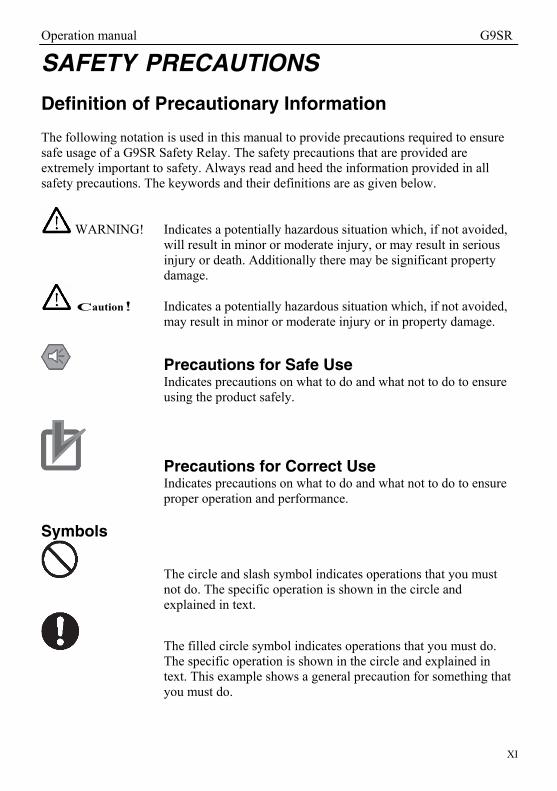
Definition of Precautionary Information The following notation is used in this manual to provide precautions required to ensure safe usage of a G9SR Safety Relay. The safety precautions that are provided are extremely important to safety. Always read and heed the information provided in all safety precautions. The keywords and their definitions are as given below.
WARNING! Indicates a potentially hazardous situation which, if not avoided, will result in minor or moderate injury, or may result in serious injury or death. Additionally there may be significant property damage.
Caution! Indicates a potentially hazardous situation which, if not avoided, may result in minor or moderate injury or in property damage.
Precautions for Safe Use Indicates precautions on what to do and what not to do to ensure using the product safely.
Precautions for Correct Use Indicates precautions on what to do and what not to do to ensure proper operation and performance.
Symbols
The circle and slash symbol indicates operations that you must not do. The specific operation is shown in the circle and explained in text.
The filled circle symbol indicates operations that you must do. The specific operation is shown in the circle and explained in text. This example shows a general precaution for something that you must do.

Operation manual G9SR
XII
In order to use the G9SR system safely, the precautions listed in this manual indicated by alert symbols and descriptions must be followed. Failure to follow all precautions and alerts may result in an unsafe use or operation. The design of a safety control function follows the requirements of: - the risk assessment acc. EN ISO 12100-1. This step defines the measures needed in risk reduction. - the basic principles of machinery safety acc. EN ISO 13849-1 - the basic principles for electrical safety acc. EN 60204-1 In addition it is required to check the structure of the entire safety system (EN ISO 13849-1), the diagnostic coverage and the robustness against common cause failures. This all is needed to check the calculation of the safety system reliability. The customer must implement measures to ensure compliance with these standards. After installation, a comparison between the specified and the installed safety function is mandatory. This final step is verifying the function of the safety system. Make sure that in the final step that all requirements defined based on the risk assessment are met. Detailed information about validation can be found in ISO 13849-2.

Operation manual G9SR
XIII
Important Safety warnings
WARNING! Read and understand this section prior to installing a G9SR system.
Whether a specific machine application and G9SR system installation complies with applicable directives and standards depends on the proper application, installation, maintenance and operation of the G9SR system. These items are the responsibility of the purchaser, installer and employer. The employer is responsible for the selection and training of personnel to properly install, operate and maintain the machine and its safeguarding systems. A G9SR system should only be installed verified and maintained by a qualified person. A qualified person is defined as "an individual who understands, is trained on, and demonstrates competence with the construction, operation or maintenance of the machinery and the hazards involved." To use the G9SR system the following requirements must be met:
• Observe the instructions in this manual regarding test regulations (e.g. on use, mounting, installation or integration into the existing machine control system) carefully.
• Periodic tests must be carried out by specialist personnel or specially qualified and authorized personnel and must be recorded and documented to ensure that the tests can be reconstructed and retraced at any time.
• The operating instructions must be made available to the operator of the machine where the G9SR system is installed.
• The machine operator is to be instructed in the use of the device by specialist personnel and must be instructed to read the operating instructions.
• The guarded machine must have a consistent stopping time and adequate control mechanisms.
This manual refers to FW release 1.0.0 and HW release 1.0 and 2.0.

Operation manual G9SR
XIV
WARNING This is the Operation Manual for the G9SR Safety Relays. Obey the following warnings during system construction to ensure that safety-related components are configured to enable the system functions to sufficiently operate. ● Risk Assessment
The proper use of the safety devices described in this manual as they relate to installation conditions and mechanical performance and functions is a prerequisite for its use. When selecting or using the safety devices, risk assessment must be performed during the development stage of the equipment or facilities to identify potential danger factors in equipment or facilities in which the safety devices are to be applied. Suitable safety devices must be selected under the guidance of a sufficient risk assessment system. An insufficient risk assessment system may result in the selection of unsuitable safety devices. • Typical related international standards: EN ISO 12100-1, Safety of Machinery --
Principles of Risk Assessment
● Safety Measures When using this safety device to build systems containing safety-related components for equipment or facilities, the system must be designed with the full understanding of and conformance to international standards, such as those listed below, and/or standards in related industries. • Typical related international standards: EN ISO 12100-1, Safety of Machinery --
Basic Concepts and General Principles for Design EN 61508, Safety Standard for Safety Instrumented Systems (Functional Safety of Electrical/Electronic/ Programmable Electronic Safety-related Systems)
● Role of Safety Devices The safety devices are provided with safety functions and mechanisms as stipulated in relevant standards, but suitable designs must be used to enable these functions and mechanisms to operate properly inside system constructions containing safety-related components. Build systems that enable these functions and mechanisms to perform properly, based on a full understanding of their operation. • Typical related international standards: ISO 14119, Safety of machinery --
Interlocking devices associated with guards -- Principles for design and selection

Operation manual G9SR
XV
WARNING
● Installation of Safety Devices The construction and installation of systems with safety-related components for equipment or facilities must be performed by technicians who have received suitable training. • Typical related international standards: EN ISO 12100-1, Safety of Machinery --
Basic Concepts and General Principles for Design EN 61508, Safety Standard for Safety Instrumented Systems (Functional Safety of Electrical/Electronic/ Programmable Electronic Safety-related Systems)
● Compliance with Laws and Regulations
This safety device conforms to the relevant regulations and standards, but make sure that it is used in compliance with local regulations and standards for the equipment or facilities in which it is applied. • Typical related international standards: EN 60204, Safety of Machinery --
Electrical Equipment of Machines
● Observing Precautions for Use When putting the selected safety device to actual use, heed the specifications and precautions in this manual and those in the instruction manual that comes with the product. Using a product in a manner that deviates from these specifications and precautions will lead to unexpected failures in equipment or devices, and to damage resulting from such failures, due to insufficient operating functions in safety-related components.
● Moving or Transferring Devices or Equipment When moving or transferring devices or equipment, be sure to include this manual to ensure that the person to whom the device or equipment is being moved or transferred will be able to operate it properly. • Typical related international standards: EN ISO 12100-1, Safety of Machinery --
Basic Concepts and General Principles for Design EN 61508, Safety Standard for Safety Instrumented Systems (Functional Safety of Electrical/Electronic/ Programmable Electronic Safety-related Systems)

Operation manual G9SR
XVI
WARNING Electric shock may occur. Do not touch any terminals while power is being supplied.
Serious injury may possibly occur due to loss of required safety functions. Do not use the G9SR Safety Relay's test outputs or standard outputs as safety outputs.
Serious injury may possibly occur due to loss of required safety functions. Do not use indicators on the G9SR Safety Relay for safety operations.
Serious injury may possibly occur due to breakdown of safety outputs or test outputs. Do not connect loads beyond the rated values to the safety outputs and test outputs.
Serious injury may possibly occur due to loss of required safety functions. Wire the G9SR series Controller properly so that the 24VDC line does NOT touch the outputs accidentally or unintentionally.
Do not try to disassemble, repair, or modify this product. Doing so may cause the safety functions to stop working properly.
Do not use the G9SR Safety Relays in environments where flammable or explosive gases are present. Doing so may result in an explosion.
Do not use the auxiliary output for safety applications.
Do not connect the 0V line to PE. Serious injury may possibly occur due to loss of required safety functions.
Serious injury may possibly occur due to loss of required safety functions. Perform user testing and confirm that all of the G9SR Safety Relay’s configuration data and operation is correct before starting system operation.
Serious injury may possibly occur due to loss of required safety functions. When replacing a G9SR Safety Relay, confirm the model of the Controller is correct and configure the replacement Controller suitably and confirm that it operates correctly.
Serious injury may possibly occur due to loss of required safety functions. Use devices and parts related to safety functions according to legal regulations in the applicable country. Use certified items compliant with safety standards corresponding to the intended application.
Perform daily and 6-monthly inspections for the G9SR Safety Relays. Otherwise, the system may fail to work properly, resulting in serious injury.

Operation manual G9SR
XVII
CAUTION Connect the AD201-□ and EX031-□ units to the same power supply.
Do not remove a terminal block while the unit is powered ON. It may damage the unit.
Do not remove the 0V connection while the unit is powered ON. It may damage the unit.
Operation manual G9SR
XVIII
PRECAUTIONS FOR SAFE USE ● Handling Do not drop the G9SR Safety Relay or subject it to excessive vibration or mechanical shock. The G9SR Safety Relay may be damaged and may not function properly. ● Installation and Storage Environment Do not use or store the G9SR Safety Relay in any of the following locations: • Locations subject to direct sunlight • Locations subject to temperatures or humidity outside the range specified in the
specifications • Locations subject to condensation as the result of severe changes in temperature • Locations subject to corrosive or flammable gases • Locations subject to dust (especially iron dust) or salts • Locations subject to water, oil, or chemicals • Locations subject to shock or vibration • The information of section ‘Operating Environment’ (§2.1 on page 4) is also
applicable for storage and transport of G9SR products. Take appropriate and sufficient measures when installing systems in the following locations. Inappropriate and insufficient measures may result in malfunction. • Locations subject to static electricity or other forms of noise • Locations subject to strong electromagnetic fields • Locations subject to possible exposure to radioactivity • Locations close to power supplies This is a class A product designed for use in industrial environments. In residential areas it may cause radio interference, in which case the user may be required to take adequate measures to reduce interference. ● Installation and Mounting • After unpacking and before installing the G9SR system please check the mechanical
condition of the system carefully. Do not install a mechanically damaged product. Return this to your OMRON service for inspection or repair. Failure to do so may result in serious injury.
• Do not drop the products. Dropping the products may lead to internal or external damage. Please return a G9SR system that was dropped on the floor to your OMRON service for inspection or repair. Failure to do so may result in serious injury.
• Make sure to test the operation of the G9SR system after installation to verify that the G9SR system operates as intended. Make sure to stop the machine until the test is completed. Unintended function settings may cause serious injury.
• Configure the system with an interlock function that prevents the machine from being restarted. Failure to do so may result in serious injury.
• Install the interlock switch in a location that provides a clear view of the entire hazardous area and where it cannot be activated from within the hazardous area.
Operation manual G9SR
XIX
• External indicators (if applicable) must be installed where they are clearly visible to workers from all the operating positions.
• Make sure that the G9SR system is securely mounted and its cables and connectors are properly connected.
• Make sure that foreign objects such as water, oil, or dust do not enter the inside of the G9SR system.
• Perform an inspection for all G9SR systems (as described in section 3 Test on page 7) when using series connections, perform inspections for every connected G9SR system.
• Use the G9SR Safety Relay within an enclosure with IP54 protection or higher according to IEC/ EN 60529.
• Use DIN Track (TH35-7.5/TH35-15 according to IEC 60715) to install the G9SR Safety Relay into the control panel.
• Mount the G9SR Safety Relay to the DIN Track using PFP-M End Plates (not included with the G9SR Safety Relay) to prevent it from falling off the DIN Track because of vibration. Correctly mount all Units to the DIN Track.
• Install the G9SR Safety Relay in the vertical direction to ensure adequate cooling. See also § 2.2 Step 2: Mechanical installation on page 4.
• Space must be provided around the G9SR Safety Relay, at least 25 mm from its side surfaces and at least 50 mm from its top and bottom surfaces, for ventilation, wiring and Unit replacement.
• Be sure to lock all locking mechanisms, such as those on I/O terminal blocks and connectors, before attempting to use the G9SR Safety Relay.
Turn OFF the power supply before performing any of the following. • Connecting or disconnecting Expansion I/O Units, Option Boards, or any other Units • Assembling the G9SR Safety Relay • Connecting cables or wiring • Connecting or removing terminal blocks ● Installation and Wiring • Disconnect the G9SR Safety Relay from the power supply before starting wiring.
Devices connected to the G9SR Safety Relay may operate unexpectedly. • Properly apply the specified voltage to the G9SR Safety Relay inputs. Applying an
inappropriate DC voltage or any AC voltage may result in a product failure, reduced safety functions, damage to the product.
• Be sure to separate the communications cables and I/O cables from high-voltage/high-current lines.
• Be cautious not to get your fingers caught when attaching terminal blocks to the G9SR Safety Relay.
• Incorrect wiring may lead to loss of safety functions. Wire conductors correctly and verify the operation of the G9SR Safety Relay before using the system in which the G9SR Safety Relay is incorporated.
• Connect no more than the specified number of additional G9SR-BC units and/or G9SR-EX units to a G9SR-AD unit.

Operation manual G9SR
XX
• Do not short-circuit the output line to the +24V line of the G9SR-BC□-□ because it will set the output to (always) ON.
• Do not connect the 0V of the power supply to Protective Earth (PE). • Ensure the configuration of the system complies with the required performance level
(PLr) of the safety control system that is defined during the risk assessment for the machine according EN ISO 12100-1.
• Do not connect any of the input lines to a DC power supply of more than 24V DC+20%. Do not connect the input lines to an AC source. An AC power supply (>30 VAC) may damage the unit.
• Ensure that the AD201-□ and EX031-□ units are connected to the same power supply.
• Do not use the auxiliary output for safety applications. ● Power Supply Selection Use a DC power supply satisfying the following requirements. • The secondary circuit of the DC power supply must be isolated from the primary
circuit by double insulation or reinforced insulation. • The output characteristic requirements defined in UL 508 for class 2 circuits or
control voltage current circuits are satisfied. • The output hold time must be 20ms or longer. • The DC power supply must be an SELV power supply that satisfies the requirements
of IEC/EN 60950-1 and EN 50178. • The power supply must be limited to a maximum current of 8A.
● Periodic Inspections and Maintenance • Disconnect the G9SR Safety Relay from the power supply before replacing the
Relay. Devices connected to the G9SR Safety Relay may operate unexpectedly. • Do not disassemble, repair, or modify the G9SR Safety Relay. Doing so may lead to
loss of safety functions.
● Disposal Be cautious not to injure yourself when dismantling the G9SR Safety Relay. This product has been designed to minimize environmental impact. For this reason please note that disposal of irreparable/unserviceable devices has to be in compliance with your local/national rules and regulations.

Operation manual G9SR
XXI
PRECAUTIONS FOR COMPLIANCE WITH UL STANDARDS AND CSA STANDARDS Use the following installation information instead of the general information in the instruction manual in order to use the product under certified conditions of UL and CSA when the product is installed in the USA or Canada. These conditions are required by NFPA 70 (National Electrical Code in the USA) and Part 1 of the Canadian Electrical Code in Canada and may vary from information given in the product manuals or safety precautions. • Surrounding air temperature: 55°C • The DC power supply must satisfy the requirements for an isolated power supply
with external 8 A overcurrent protection. ● Ratings
G9SR Safety Relay Standards G9SR-BC Source: 24V DC, 5A max
Input: 24V DC, 6mA Output: 24V DC/2A max each OSSD 24V DC for AUX max 0.5A
G9SR-AD Source: 24V DC, 1A max Input: 24V DC, 6mA Output: 24V DC for AUX only max 0.5A Relay output: see detailed specifications
G9SR-EX Source: 24V DC, 1A max Input: 24V DC, 6mA Output: 24V DC for AUX only max 0.5A Relay output: see detailed specifications
Operation manual G9SR
XXII
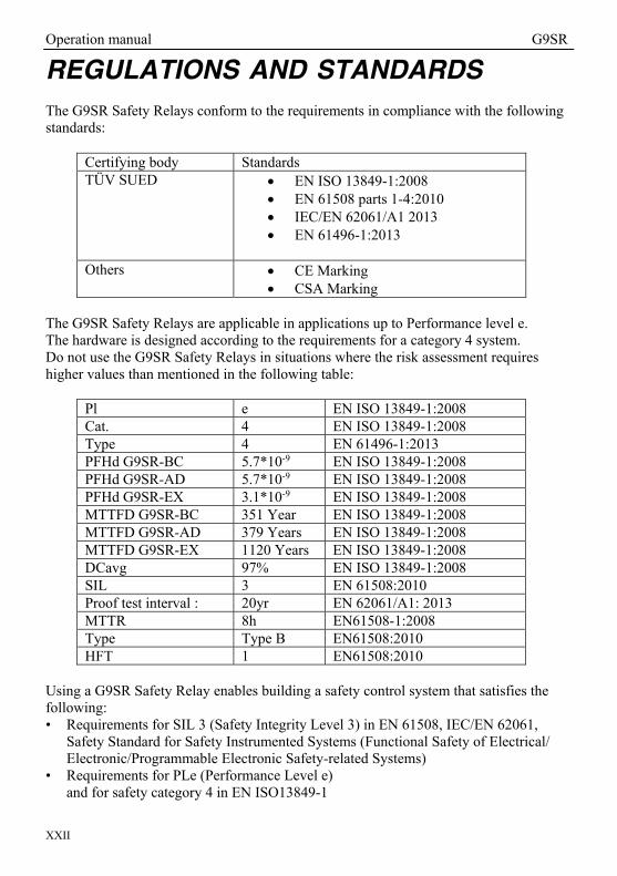
REGULATIONS AND STANDARDS The G9SR Safety Relays conform to the requirements in compliance with the following standards:
Certifying body Standards TÜV SUED EN ISO 13849-1:2008
EN 61508 parts 1-4:2010 IEC/EN 62061/A1 2013 EN 61496-1:2013
Others CE Marking
CSA Marking The G9SR Safety Relays are applicable in applications up to Performance level e. The hardware is designed according to the requirements for a category 4 system. Do not use the G9SR Safety Relays in situations where the risk assessment requires higher values than mentioned in the following table:
Pl e EN ISO 13849-1:2008 Cat. 4 EN ISO 13849-1:2008 Type 4 EN 61496-1:2013 PFHd G9SR-BC 5.7*10-9 EN ISO 13849-1:2008 PFHd G9SR-AD 5.7*10-9 EN ISO 13849-1:2008 PFHd G9SR-EX 3.1*10-9 EN ISO 13849-1:2008 MTTFD G9SR-BC 351 Year EN ISO 13849-1:2008 MTTFD G9SR-AD 379 Years EN ISO 13849-1:2008 MTTFD G9SR-EX 1120 Years EN ISO 13849-1:2008 DCavg 97% EN ISO 13849-1:2008 SIL 3 EN 61508:2010 Proof test interval : 20yr EN 62061/A1: 2013 MTTR 8h EN61508-1:2008 Type Type B EN61508:2010 HFT 1 EN61508:2010
Using a G9SR Safety Relay enables building a safety control system that satisfies the following: • Requirements for SIL 3 (Safety Integrity Level 3) in EN 61508, IEC/EN 62061,
Safety Standard for Safety Instrumented Systems (Functional Safety of Electrical/ Electronic/Programmable Electronic Safety-related Systems)
• Requirements for PLe (Performance Level e) and for safety category 4 in EN ISO13849-1

Operation manual G9SR
XXIII
COMPLIANCE WITH EC DIRECTIVES APPLICABLE DIRECTIVES The national/international rules and regulations apply to the installation, use and periodical technical inspections of the safety system, in particular: • Machinery Directive (2006/42/EC) • EMC Directive (2014/30/EU)
Concepts ● EMC Directive OMRON electrical devices are built into other components or equipment. OMRON therefore pursues compliance with the related EMC standards so that they can be more easily built into other devices or the equipment.* OMRON cannot confirm compliance in the customer's actual application; however, because the customer may use a variety of components and equipment, and EMC performance depends on the configuration, wiring, and arrangement of the equipment and control panel into which a product applicable to EC Directives is incorporated. Therefore, whether the products conform to the standards in the system used by the customer, they must be checked by the customer.
* Applicable EMC (Electromagnetic Compatibility) standards are as follows: EN 61000-6-2 for EMS (Electromagnetic Susceptibility) and EN 61000-6-4 for Electromagnetic Interference (10-m regulations applied for EN 61000-6-4 radiated emission).

Operation manual G9SR
XXIV
● Conformance to EC Directives The G9SR Safety Relays complies with EC Directives. To ensure that the machine or device in which the G9SR Safety Relay is used complies with EC Directives, the following requirements must be met. • Make sure that the DC power supply connected to a DC Power Supply Unit or I/O
Unit satisfies the following conditions. • There is double insulation or reinforced insulation between the primary circuit
and secondary circuit. • An isolated power supply that is limited to a current of 8 A or lower must be
used. • The output hold time is 20ms min. • The power supply is a SELV power supply that satisfies requirements in IEC/ EN
60950-1 and EN 50178. • Provide external measures to ensure appropriate overvoltage protection to a
maximum of 30V DC. • G9SR-series products that comply with the EC Directives also comply with the
Generic Emission Standard (EN 61000-6-4) for EMI. The radiated emission characteristics (10-m regulations), however, may depend on the configuration of the control panel that is used and the relation to and wiring with other connected devices. Even through the G9SR Safety Relay complies with EC Directives; the customer must confirm that the overall machinery and equipment in which the G9SR Safety Relay is used complies with the EC Directives.
The customer must implement measures to ensure compliance with these standards. CE conformity declaration available at: http://industrial.omron.eu ● Machinery Directive The Machinery Directive requires ensuring the required safety for safety components used for machinery safety. Applicable standards: EN ISO 13849-1:2008 and IEC/EN 62061 SIL CL3

Operation manual G9SR
XXV
GLOSSARY, DEFINITIONS, ABBREVIATIONS
Aux.: Auxiliary. E.g. Auxiliary Outputs
Dynamic Input testing:
Test if the separate input channels are connected (shorted). Applicable to G9SR-BC□-□ and G9SR-AD□-□
EDM: External Device Monitoring;
Active checking of the correct behavior of external connected units like safety relays.
ESPE: Electro Sensitive Protective Equipment
Assemblies of • a sensing device • controlling/monitoring devices • Output Signal Switching Device (OSSD)
FA: Factory Automation
G9SR-BC□-□: A Basic unit (BC) of the G9SR series.
G9SR-AD□-□: An Advanced unit (AD) of the G9SR series.
G9SR-EX□-T90-□: An Extension unit (EX) of the G9SR series.
Input: Signal going into the unit. Input signals can come from e.g. safety
sensors, E-stop switches or SLCs.
Lock out State: A forced OFF state, the OSSDs are OFF. This state can be reached when an error occurs in the complete system. Power cycle the unit to exit this State.
MPU: Micro Processing Unit.
NO / NC: Normally Opened / Normally Closed The contact situation of switching devices (switches, relays,..) when not powered/activated.
OSSD: Output Signal Switching Device.
OSSD can be safety relays with mechanical contacts or solid state outputs such as PNP-transistors.

Operation manual G9SR
XXVI
PFHd: Probability Failures per Hour that are Dangerous
PL: Performance Level as defined in ISO 13849-1
RESTART: A sequence of the total system to come from a non-powered situation to an operational situation. In an operational situation OSSDs can be activated (ON) when a valid input signal is received.
Safe State: A forced OFF state, the OSSDs are OFF.
SLC: Safety Light Curtain.

Operation manual G9SR
Page 1 of 79
1 Product family – General information
1.1 Intended use
The G9SR units are intended for the functions listed in the table below: G9SR-BC G9SR-AD G9SR-EX E-Stop function Yes Yes No Door monitoring (safety limit switches) Yes Yes No Door monitoring (key operated switches) Yes Yes No Door monitoring (non-contact switches) Yes Yes No ESPE monitoring Yes Yes No Additional safety outputs No No Yes Note on the G9SR-EX unit: The extra outputs realised with the G9SR-EX units have an ON-delay timer and an OFF-delay timer for additional control of your outputs.
1.2 Family Overview
The product family G9SR consists of a G9SR-BC□-□ (BC = Basic), a G9SR-AD□-□ (AD = Advanced) and a G9SR-EX□-T90-□ unit (EX = Extension) to give you flexibility when configuring your specific system.
1.2.1 G9SR-BC
The G9SR-BC has a double channel safety input that can be used in E-Stop, door monitoring applications or applications with opto-electronic safety sensors. The G9SR-BC has solid state safety outputs for DC loads of up to 2A and with a peak current up to 5A. The G9SR-BC can operate standalone or as an additional input with a G9SR-AD. The G9SR-BC has an auxiliary output with configurable state using dedicated dipswitch. See also: Chapter 6 G9SR unit: G9SR-BC□-□ on page 19.
Operation manual G9SR
Page 2 of 79
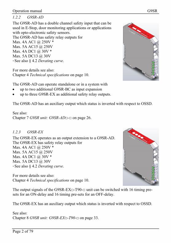
1.2.2 G9SR-AD
The G9SR-AD has a double channel safety input that can be used in E-Stop, door monitoring applications or applications with opto-electronic safety sensors. The G9SR-AD has safety relay outputs for Max. 4A AC1 @ 250V * Max. 5A AC15 @ 250V Max. 4A DC1 @ 30V * Max. 5A DC13 @ 30V * See also § 4.2 Derating curve. For more details see also: Chapter 4 Technical specifications on page 10. The G9SR-AD can operate standalone or in a system with up to two additional G9SR-BC as input expansion up to three G9SR-EX as additional safety relay outputs.
The G9SR-AD has an auxiliary output which status is inverted with respect to OSSD. See also: Chapter 7 G9SR unit: G9SR-AD□-□ on page 26.
1.2.3 G9SR-EX
The G9SR-EX operates as an output extension to a G9SR-AD. The G9SR-EX has safety relay outputs for Max. 4A AC1 @ 250V * Max. 5A AC15 @ 250V Max. 4A DC1 @ 30V * Max. 5A DC13 @ 30V * See also § 4.2 Derating curve. For more details see also: Chapter 4 Technical specifications on page 10. The output signals of the G9SR-EX□-T90-□ unit can be switched with 16 timing pre-sets for an ON-delay and 16 timing pre-sets for an OFF-delay. The G9SR-EX has an auxiliary output which status is inverted with respect to OSSD. See also: Chapter 8 G9SR unit: G9SR-EX□-T90-□ on page 33.
Operation manual G9SR
Page 3 of 79
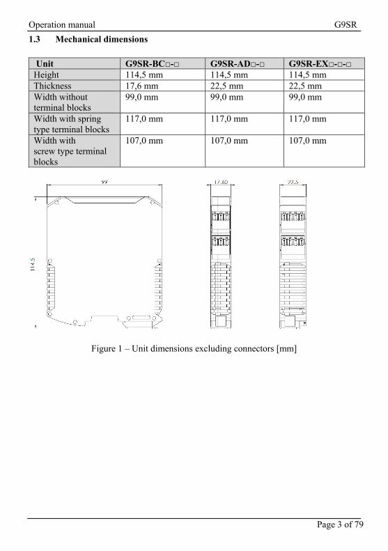
1.3 Mechanical dimensions
Unit G9SR-BC□-□ G9SR-AD□-□ G9SR-EX□-□-□ Height 114,5 mm 114,5 mm 114,5 mm Thickness 17,6 mm 22,5 mm 22,5 mm Width without terminal blocks
99,0 mm 99,0 mm 99,0 mm
Width with spring type terminal blocks
117,0 mm 117,0 mm 117,0 mm
Width with screw type terminal blocks
107,0 mm 107,0 mm 107,0 mm
Figure 1 – Unit dimensions excluding connectors [mm]
Operation manual G9SR
Page 4 of 79
2 Installation and configuration To install G9SR units:
2.1 Step 1: Installation environment
Disconnect all electrical power sources before installing and connecting a G9SR unit. Ensure the environment is with the specifications as mentioned in Chapter 4 Technical specifications on page 10. See also: § Precautions for Safe Use
• Installation and Mounting on page 18
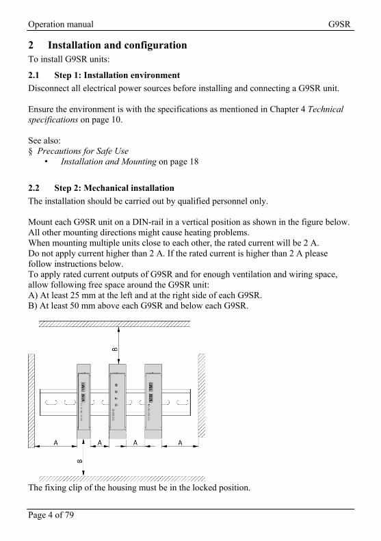
2.2 Step 2: Mechanical installation
The installation should be carried out by qualified personnel only. Mount each G9SR unit on a DIN-rail in a vertical position as shown in the figure below. All other mounting directions might cause heating problems. When mounting multiple units close to each other, the rated current will be 2 A. Do not apply current higher than 2 A. If the rated current is higher than 2 A please follow instructions below. To apply rated current outputs of G9SR and for enough ventilation and wiring space, allow following free space around the G9SR unit: A) At least 25 mm at the left and at the right side of each G9SR. B) At least 50 mm above each G9SR and below each G9SR.
The fixing clip of the housing must be in the locked position.

Operation manual G9SR
Page 5 of 79
2.3 Step 3: Electrical installation
The electrical installation should be carried out by qualified personnel only. Electrical installation requirements and configurations are the outcome of the machinery risk assessment.
WARNING! Remove the power from your system before installing a G9SR unit.
Caution! Prevent wire clippings from entering the unit. See also: § Precautions for Safe Use
• Installation and Wiring on page 19 • Power Supply Selection on page 20
Chapter 4 Technical specifications on page 10 for wiring details. Chapter 11 Appendix A: Wiring examples on page 52 § 10.1 Input loop on page 49 § 10.2 Output loop on page 50 § 10.3 Input loop and Output loop on page 51
2.3.1 Install fuses for G9SR units
G9SR units require external protection of the power supply lines. If several G9SR units are installed, each of the individual G9SR modules requires a separate fuse.
Caution! Install a fuse for each G9SR units. • for each G9SR-AD□-□ a 1A Fast fuse • for each G9SR-BC□-□ a 5A Fast fuse • for each G9SR-EX□-T90-□ a 1A Fast fuse
2.3.2 Install fuses for output relays
Include a 5A Fast fuse for each power supply line to the output relays.
2.3.3 Install Power Supply
Add the power supply for the units and for the installed outputs.
Caution! Connect the AD201-□ and EX031-□ units to the same power supply.
Operation manual G9SR
Page 6 of 79
2.3.4 G9SR-BC□-□ solid state output
Caution! In accordance with EN-61131-2 G9SR-BC□-□ outputs are not compatible with type 1 inputs.
Caution! In accordance with EN-61131-2 G9SR-BC□-□ outputs are compatible with type 2 and type 3 outputs with an external load < 1Kohm.
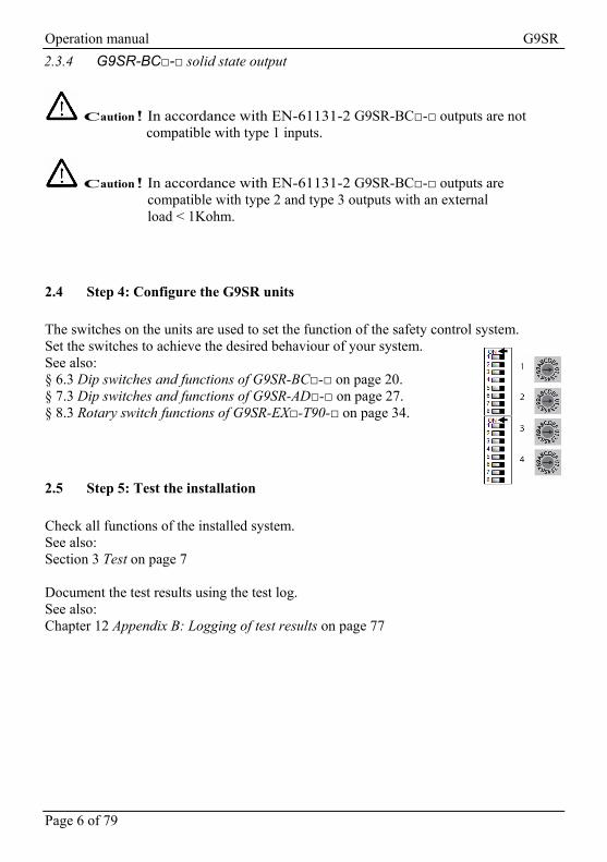
2.4 Step 4: Configure the G9SR units
The switches on the units are used to set the function of the safety control system. Set the switches to achieve the desired behaviour of your system. See also: § 6.3 Dip switches and functions of G9SR-BC□-□ on page 20. § 7.3 Dip switches and functions of G9SR-AD□-□ on page 27. § 8.3 Rotary switch functions of G9SR-EX□-T90-□ on page 34.
2.5 Step 5: Test the installation
Check all functions of the installed system. See also: Section 3 Test on page 7 Document the test results using the test log. See also: Chapter 12 Appendix B: Logging of test results on page 77

Operation manual G9SR
Page 7 of 79
3 Test Perform the tests always:
after installation after every system maintenance action after a change in settings (dip switches or rotary switches) periodically according to the local requirements
(local standards and/or safety rules)
WARNING! Incorrect testing can cause potentially hazardous situations which, if not avoided, could result in death or serious injury. Additionally, there may be severe property damage.
Test procedure:
1. Test the OFF behaviour. See § 3.1 on page 8 2. Test the ON behaviour. See § 3.2 on page 9 3. Log the test results. See Appendix B: Logging of test results on page 77

Operation manual G9SR
Page 8 of 79
3.1 Test the OFF behaviour

Operation manual G9SR
Page 9 of 79
3.2 Test the ON behaviour

Operation manual G9SR
Page 10 of 79
4 Technical specifications
4.1 General specifications
Item Value Mounting DIN rail
Housing Material & Connectors Plastic (grey) Dimensions, see page 3
Connectors Removable cage clamp terminals Operating temperature range -10°C to + 55°C Storage temperature range -25°C to + 70°C Humidity 0 to 95% RH. No icing or condensation Enclosure rating (EN 60529) IP20 (mount in a IP54 cabinet or higher
according to IEC/ EN 60529 ) Resistance to Vibration (to IEC 68-2-6) Shock (to IEC 68-2-27)
0,375mm 10 to 70 Hz 30G 18ms
Operating voltage 24V DC ± 20%
Current consumption excluding auxiliary output
<0.15A
Minimum EDM and RESTART input current
6mA
Minimum EDM and RESTART voltage for an ON signal
19V DC
Minimum voltage for T12 and T22 for an ON signal
17V DC
Minimum input current for T12 and T22
6mA
Maximum T12, T22, EDM and RESTART voltage for an OFF signal
11V DC
Power-ON delay < 2 sec. Outputs static G9SR-BC Output voltage High G9SR-BC Output voltage Low
2A continuous for OSSD 0.5A for Auxiliary output Unit supply voltage -1V 0V
Output relay on –AD and -EX
Max. 4A AC1* Max. 5A AC15 Max. 4A DC1* Max. 5A DC13 * See also § 4.2 Derating curve.
Operation manual G9SR
Page 11 of 79
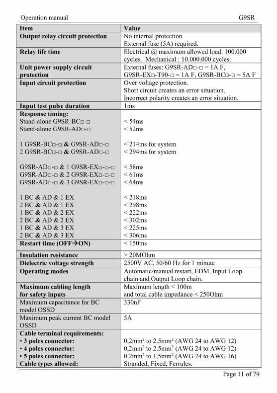
Item Value Output relay circuit protection No internal protection
External fuse (5A) required. Relay life time Electrical @ maximum allowed load: 100.000
cycles. Mechanical : 10.000.000 cycles. Unit power supply circuit protection
External fuses: G9SR-AD□-□ = 1A F, G9SR-EX□-T90-□ = 1A F, G9SR-BC□-□ = 5A F
Input circuit protection Over voltage protection. Short circuit creates an error situation. Incorrect polarity creates an error situation.
Input test pulse duration 1ms Response timing: Stand-alone G9SR-BC□-□ Stand-alone G9SR-AD□-□ 1 G9SR-BC□-□ & G9SR-AD□-□ 2 G9SR-BC□-□ & G9SR-AD□-□ G9SR-AD□-□ & 1 G9SR-EX□-□-□ G9SR-AD□-□ & 2 G9SR-EX□-□-□ G9SR-AD□-□ & 3 G9SR-EX□-□-□ 1 BC & AD & 1 EX 2 BC & AD & 1 EX 1 BC & AD & 2 EX 2 BC & AD & 2 EX 1 BC & AD & 3 EX 2 BC & AD & 3 EX
< 54ms < 52ms < 214ms for system < 294ms for system < 58ms < 61ms < 64ms < 218ms < 298ms < 222ms < 302ms < 225ms < 306ms
Restart time (OFFON) < 150ms
Insulation resistance > 20MOhm Dielectric voltage strength 2500V AC, 50/60 Hz for 1 minute Operating modes Automatic/manual restart, EDM, Input Loop
chain and Output Loop chain. Maximum cabling length for safety inputs
Maximum length < 100m and total cable impedance < 250Ohm
Maximum capacitance for BC model OSSD
330nF
Maximum peak current BC model OSSD
5A
Cable terminal requirements: • 3 poles connector: • 4 poles connector: • 5 poles connector: Cable types allowed:
0,2mm2 to 2.5mm2 (AWG 24 to AWG 12) 0,2mm2 to 2.5mm2 (AWG 24 to AWG 12) 0,2mm2 to 1,5mm2 (AWG 24 to AWG 16) Stranded, Fixed, Ferrules.

Operation manual G9SR
Page 12 of 79
Item Value Power supply requirement Double insulation acc. EN 60950
4.2 Derating curve of relay contact current
The temperature of the modules is influenced by Load Current [A] and the distance [25 mm] between units. Use the derating curve to determine the maximum allowed relay contact current for the actual operating temperature of the unit. This applies to each single relay contact.
-10°C
30°C
55°C
25°C
50°C Note: The graph is valid for an environment temperature of 21 °C and
with each contact driving the same current at the same time. Note: When mounting multiple units close to each other, the rated
current will be 2A. Do not apply current higher than 2A. If the rated current is higher than 2A please follow instructions at 2.2 Step 2: Mechanical installation

Operation manual G9SR
Page 13 of 79
Test pattern for OSSD Testing
Ta = OSSD1 test pulse1 with a duration of <250 micro second Tb = OSSD1 test pulse2 with a duration of <350 micro second Tres = Cycle time of the complete G9SR unit
4.3 Test pattern for Dynamic Input testing
Test pattern with an input channel test pulse of 1 ms.
Tres
<1ms <1ms
T11
T21
t
Tres = Cycle time of the complete G9SR unit

Operation manual G9SR
Page 14 of 79
5 Restart modes There are two possible restart modes:
Manual Restart See § 5.1 on page 14 Automatic Restart See § 5.3 on page 17
5.1 Manual Restart
If Manual restart is selected and there is an intervention then the system will not restart automatically. To restart the system, activate the restart signal manually. Operating modes for Manual Restart input The wiring of the G9SR Restart input is depending on the DIP-switch setting. 1) DIP-switch 2 = "ON" The G9SR monitors to detect unexpected signals between all terminals and/or power supply for full diagnosis and error detection.
The source for the Restart input T31 is the terminal T11. The Restart function will not be enabled if the source for T31 is any other
terminal than T11. 1) DIP-switch 2 = "OFF" The G9SR is not monitoring unexpected signals to power supply or other terminals of the unit.
The source for the Restart input T31 is +24VDC. See also: Chapter 11 Appendix A: Wiring examples on page 52

Operation manual G9SR
Page 15 of 79
TOn = On-delay time set on the G9SR-EX TOff = OFF-delay time set on the G9SR-EX TResMin = Minimum Restart input pulse 300ms
WARNING! Make sure that the source of the restart signal is complementing the requirements for the safety control system. Improper use of the restart input may lead to a dangerous situation due to unintended restart of the machine.
5.2 Wiring examples Manual Restart
Wiring of the Restart function is similar for the G9SR-BC and the G9SR-AD units. Two wiring examples for Manual Restart:

Operation manual G9SR
Page 16 of 79
5.2.1 Manual Restart with dynamic input testing
5.2.2 Manual Restart without dynamic input testing
Operation manual G9SR
Page 17 of 79
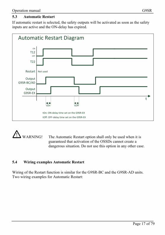
5.3 Automatic Restart
If automatic restart is selected, the safety outputs will be activated as soon as the safety inputs are active and the ON-delay has expired.
t
T12
T22
Restart
OutputG9SR-BC/AD
OutputG9SR-EX
tOn tOff
tOn: ON-delay time set on the G9SR-EX
tOff: OFF-delay time set on the G9SR-EX
Automatic Restart Diagram
Not used
ON
OFF
WARNING! The Automatic Restart option shall only be used when it is guaranteed that activation of the OSSDs cannot create a dangerous situation. Do not use this option in any other case.
5.4 Wiring examples Automatic Restart
Wiring of the Restart function is similar for the G9SR-BC and the G9SR-AD units. Two wiring examples for Automatic Restart:

Operation manual G9SR
Page 18 of 79
5.4.1 Automatic Restart with dynamic input testing
5.4.2 Automatic Restart without dynamic input testing

Operation manual G9SR
Page 19 of 79
6 G9SR unit: G9SR-BC□-□
6.1 Introduction
The G9SR-BC□-□ unit can handle one double-channel input device and 2 output signals. The outputs have to be DC loads with a maximum of 2A switching current each. This unit can be used stand-alone or as an additional Input unit for the G9SR-AD□-□. See also § 10.1 Input loop on page 49
6.2 Internal connections of G9SR-BC□-□
Figure 2 - Internal connections of G9SR-BC□-□

Operation manual G9SR
Page 20 of 79
4 3 2 1 ON
8 7 6 5
4 3 2 1 ON
8 7 6 5
6.3 Dip switches and functions of G9SR-BC□-□
The DIP-Switches are used to configure the G9SR-BC unit for the application. There are two banks of DIP-switches in the G9SR-BC. Both DIP-switch banks have eight switches. To select a function, the switches on both DIP-switch banks have to be set identically. Example: DIP SWITCH 3, BANK1 = "OFF" and DIP SWITCH 3, BANK2 = "OFF" => OK DIP SWITCH 3, BANK1 = "OFF" and DIP SWITCH 3, BANK2 = "ON" => ERROR
Caution! Do not change the setting of the DIP switches during operation of the G9SR-BC. In this case, the G9SR-BC will change the outputs to "OFF" and will enter a lockout state.
Use the switches to configure following functions: Function Switch G9SR-BC□-□ Restart
1 ON = Auto Restart OFF = Manual Restart
Dynamic Input Testing 2 ON = Enabled OFF = Disabled
EDM
3 ON = Enabled OFF = Disabled
INPUT LOOP
4 ON = input loop enabled. This disables the OSSDs and Aux out. OFF = input loop disabled
AUX OUT STATUS
5 ON = Aux out status consistent with OSSD OFF = Aux out status inverted.
6/7/8 Reserved
BA
NK
1 BA
NK
2

Operation manual G9SR
Page 21 of 79
6.4 LEDs of the G9SR-BC□-□
LEDs show the unit status and indicate errors.
An LED can be OFF shown as
ON shown as
FLASHING shown as
Not applicable shown as
6.4.1 POWER LED = POWER
Color: Green
ON when power supply is correctly applied to the unit.
OFF when no power is supplied IN1 LED = Input 1 Color: Yellow
ON when T12 receives a valid input signal.
OFF when no valid input signal is received at T12.
6.4.2 IN2 LED = Input 2
Color: Yellow
ON when T22 receives a valid input signal.
OFF when no valid input signal is received at T22.
6.4.3 RESTART LED = Restart
Color: Yellow
ON when the Restart pushbutton is activated.
FLASH when an error occurs. Fast blinking & ERR fast blinking = Communication error of another unit Slow blinking & ERR slow blinking = Communication error of this unit See also § 6.5.2Error situations - LEDs G9SR-BC□-□ on page 24
OFF when restart action is not required / not allowed.

Operation manual G9SR
Page 22 of 79
6.4.4 EDM LED = External Device Monitoring
Color: Yellow
ON when EDM function is enabled.
FLASH when any error on External Device Monitoring occurs. See also § 6.5.2Error situations - LEDs G9SR-BC□-□ on page 24
OFF EDM function is disabled.
6.4.5 ON LED = Outputs
Color: Green
ON when the outputs are activated = ON.
FLASH fast (3 per second) when input-loop chain is OK.
OFF when the outputs are de-activated = OFF.
6.4.6 OFF/ERR LED = OFF & Error
Color: Red
ON when OSSDs are OFF
FLASH when an error occurs (EDM and Restart leds provide error code). Fast blinking & RES or COM fast blinking
= Communication error of another unit Slow blinking = OSSD error.
Slow blinking & RES or COM slow blinking = Communication error of this unit. See also § 6.5.2 Error situations - LEDs G9SR-BC□-□ on page 24.
OFF when all internal diagnostics are successfully passed and OSSDs are activated = ON.

Operation manual G9SR
Page 23 of 79
6.5 LED examples G9SR-BC□-□
6.5.1 Normal operation - LEDs G9SR-BC□-□
LED signal Pattern
Description
ID
OF
F/E
RR
ON
ED
M
RE
ST
AR
T
IN2
IN1
PO
WE
R
1.
T12 ON, T22 ON. EDM enabled. Output active.
2.
Waiting for restart. EDM disabled. Output not active.
3.
T12 OFF, T22 OFF. EDM enabled. Output not active.
4.
T12 ON, T22 ON. EDM disabled. Input loop function activated, module running OK. 1)
5.
T12 OFF, T22 OFF. EDM disabled. Input loop function activated, module running OK. 1)
6.
Restart LED blinks slow, waiting for Input loop.
1) The ON green led flashes quickly to indicate the input loop function is enabled and operates correctly.

Operation manual G9SR
Page 24 of 79
6.5.2 Error situations - LEDs G9SR-BC□-□
LED signal Pattern
Description
ID
OF
F/E
RR
ON
ED
M
RE
ST
AR
T
IN2
IN1
PO
WE
R
1.
Error on EDM input
2.
Error during cyclic test. Error because other module is connected when G9SR-BC is configured with input loop.
3.
DIP switch settings incorrect.
4.
Error on solid state safety outputs (overload).
5.
ERR and RES fast blinking (3 per sec.) = communication error of another unit ERR and RES slow blinking (1 per sec.) = communication error of this unit

Operation manual G9SR
Page 25 of 79
6.6 Terminal and signal names G9SR-BC□-□
T12 Input Channel 1 44 Output Auxiliary (Status) A1 Power Supply T31 Restart Input T11 Test Signal 1 A2 Power Supply GND T32 EDM Input
or Input Loop IN (depending on dip switches) T21 Test Signal 2 14 Output 1 OSSD1
or Input Loop OUT (depending on dip switches) 24 Output 2 OSSD2 T22 Input Channel 2 See also: § 11.1 Wiring examples G9SR-BC□-□ unit on page 52.
Operation manual G9SR
Page 26 of 79
7 G9SR unit: G9SR-AD□-□
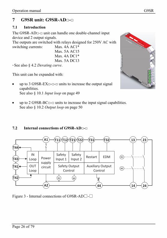
7.1 Introduction
The G9SR-AD□-□ unit can handle one double-channel input device and 2 output signals. The outputs are switched with relays designed for 250V AC with switching currents: Max. 4A AC1* Max. 5A AC15 Max. 4A DC1* Max. 5A DC13 * See also § 4.2 Derating curve. This unit can be expanded with: up to 3 G9SR-EX□-□-□ units to increase the output signal
capabilities. See also § 10.1 Input loop on page 49
up to 2 G9SR-BC□-□ units to increase the input signal capabilities. See also § 10.2 Output loop on page 50
7.2 Internal connections of G9SR-AD□-□
Figure 3 - Internal connections of G9SR-AD□-□
Powersupplycircuit
SafetyInput 1
SafetyInput 2 Restart EDM
Safety Output Control
Auxiliary Output Control
IN Loop
OUT Loop
K1 K2
K1
K2
A1 T11 T12 T21 T22 T31 T32 13 23
T43
T41
T44
T42
A2 44 14 24

Operation manual G9SR
Page 27 of 79
4 3 2 1 ON
8 7 6 5
4 3 2 1 ON
8 7 6 5
7.3 Dip switches and functions of G9SR-AD□-□
The DIP-Switches are used to configure the G9SR-AD unit for the application. There are two banks of DIP-switches in the G9SR-AD. Both DIP-switch banks have eight switches. To select a function, the switches on both DIP-switch banks have to be set identically. Example: DIP SWITCH 3, BANK1 = "OFF" and DIP SWITCH 3, BANK2 = "OFF" => OK DIP SWITCH 3, BANK1 = "OFF" and DIP SWITCH 3, BANK2 = "ON" => ERROR
Caution! Do not change the setting of the DIP switches during operation of the G9SR-AD. In this case, the G9SR-AD will change the outputs to "OFF" and will enter a lockout state.
Use the switches to configure following functions: Function Switch G9SR-AD□-□ Restart
1 ON = Auto restart OFF = Manual restart
Dynamic Input Testing 2 ON = Enabled OFF = Disabled
EDM
3 ON = Enabled OFF = Disabled
INPUT LOOP
4/5 OFF/OFF = No G9SR-BC□-□ connected OFF/ON = Setting not allowed ON/OFF = 1 G9SR-BC□-□ connected ON/ON = 2 G9SR-BC□-□ connected
OUTPUT LOOP
6/7 OFF/OFF = No G9SR-EX□-T90-□ connected OFF/ON = 1 G9SR-EX□-T90-□ connected ON/OFF = 2 G9SR-EX□-T90-□ connected ON/ON = 3 G9SR-EX□-T90-□ connected
8 Reserved
BA
NK
1 BA
NK
2

Operation manual G9SR
Page 28 of 79
7.4 LEDs of the G9SR-AD□-□
LEDs show the unit status and indicate errors.
An LED can be OFF shown as
ON shown as
FLASHING shown as
Not applicable shown as
7.4.1 POWER LED = Power
Color: Green
ON when power supply is correctly applied to the unit.
OFF when no power is supplied.
7.4.2 IN1 LED = Input 1
Color: Yellow
ON when T12 receives a valid input signal.
OFF when no valid input signal is received at T12.
7.4.3 IN2 LED = Input 2
Color: Yellow
ON when T22 receives a valid input signal.
OFF when no valid input signal is received at T22.

Operation manual G9SR
Page 29 of 79
7.4.4 RESTART LED = Restart
Color: Yellow
ON when Restart input activated.
FLASH when any error occurs. Fast blinking & ERR fast blinking = Communication error of another unit Slow blinking & ERR slow blinking = Communication error of this unit
See also § 7.5.2 Error situations - LEDs G9SR-AD□-□ on page 31.
OFF when restart action is not required / not allowed.
7.4.5 EDM LED = External Device Monitoring
Color: Yellow
ON when EDM function is enabled.
FLASH when any error on External Device Monitoring occurs.
OFF EDM function is disabled.
7.4.6 ON LED = Outputs
Color: Green
ON when the outputs are ON.
OFF when the outputs are OFF.
7.4.7 OFF/ERR LED = Error
Color: Red
ON when OSSDs are OFF System startup internal testing failed
FLASH when an error occurs (EDM and Restart leds provide error code). Fast blinking & RES or COM fast blinking = Communication error of another unit Slow blinking & RES or COM slow blinking = Communication error of this unit See also § 7.5.2 Error situations - LEDs G9SR-AD□-□ on page 31.
OFF when all internal diagnostics are successfully passed and OSSDs are ON.

Operation manual G9SR
Page 30 of 79
7.5 LED Examples G9SR-AD□-□
7.5.1 Normal operation - LEDs G9SR-AD□-□
LED signal Pattern
Description
ID
OF
F/E
RR
ON
ED
M
RE
ST
AR
T
IN2
IN1
PO
WE
R
1.
T12 ON, T22 ON. EDM disabled. Output active.
2.
T12 ON, T22 ON. EDM enabled. Output active.
3.
T12 ON, T22 ON. EDM disabled. Waiting for restart.
4.
T12 OFF, T22 OFF. EDM enabled. Outputs not active.
5.
T12 OFF, T22 OFF. EDM disabled. Outputs not active.

Operation manual G9SR
Page 31 of 79
7.5.2 Error situations - LEDs G9SR-AD□-□
LED signal Pattern
Description
ID
OF
F/E
RR
ON
ED
M
RE
ST
AR
T
IN2
IN1
PO
WE
R
1.
Error on EDM input
2.
Error during cyclic test
3.
DIP switch settings incorrect.
4.
ERR and RES fast blinking (3 per sec.) = communication error of another unit ERR and RES slow blinking (1 per sec.) = communication error of this unit

Operation manual G9SR
Page 32 of 79
7.6 Terminal and signal names of the G9SR-AD□-□ unit
13 Relay Output 1.1 (NO) 23 Relay Output 2.1 (NO) T12 Input Channel 1 44 Output Auxiliary (Status) A1 Power Supply T31 Restart Input T11 Test Signal 1 T43 Input loop IN T44 Input loop OUT A2 Power Supply GND T32 EDM input T21 Test Signal 2 T41 Output loop OUT 14 Relay Output 1.2 (NO) 24 Relay Output 2.2 (NO) T22 Input Channel 2 T42 Output loop IN See also: § 11.2 Wiring examples G9SR-AD□-□ unit on page 62.

Operation manual G9SR
Page 33 of 79
8 G9SR unit: G9SR-EX□-T90-□
8.1 Introduction
The G9SR-EX□-T90-□ unit can be connected to the G9SR-AD□-□ unit as an Output extension unit. The outputs are switched with relays designed for 250V AC with switching currents: Max. 4A AC1* Max. 5A AC15 Max. 4A DC1* Max. 5A DC13 * See also § 4.2 Derating curve. The output signals of the G9SR-EX□-T90-□ unit can be switched with 16 timing pre-sets for an ON-delay and 16 timing pre-sets for an OFF-delay. See also § 10.2 Output loop on page 50
8.2 Internal connections of G9SR-EX□-T90-□
Figure 4 - Internal connections of G9SR-EX□-T90-□

Operation manual G9SR
Page 34 of 79
8.3 Rotary switch functions of G9SR-EX□-T90-□
The rotary switches are used to configure the G9SR-EX for the application. The OFF- and ON-delay time can be set independently.
Caution! Do not change the setting of the switches during operation of the G9SR-EX. In this case, the G9SR-EX will change the outputs to "OFF" and will enter a lockout state.
There are four rotary switches in the G9SR-EX to configure the ON- and OFF-delay time setting. Switch 1 and 3 define the ON-delay time setting. Switch 2 and 4 define the OFF-delay time setting. The rotary switch settings represent following time delays: 0 1 2 3 4 5 6 7 0s 0.1s 0.2s 0.5s 1s 1.5s 2s 2.5s 8 9 A B C D E F 5s 10s 20s 30s 45s 60s 75s 90s
8.3.1 ON-delay
To select an ON-delay time, use switch 1 and switch 3. They have to be set identically for a valid ON-delay time setting.
8.3.2 OFF-delay
To select an OFF-delay time, use switch 2 and switch 4. They have to be set identically for a valid OFF-delay time setting.

Operation manual G9SR
Page 35 of 79
8.4 LEDs of the G9SR-EX□-T90-□
LEDs show the unit status and indicate errors.
An LED can be OFF shown as
ON shown as
FLASHING shown as
Not applicable shown as
8.4.1 POWER LED = Power
Color: Green
ON when power supply is correctly applied to the unit.
OFF when no power is supplied.
8.4.2 COM LED = Input
Color: Yellow
ON when the communication line sends or receives a valid signal.
FLASH when an ONdelay or OFFdelay is in progress. Fast blinking & ERR fast blinking = Communication error of another unit Slow blinking & ERR slow blinking = Communication error of this unit
OFF when no valid input signal is received on T42.
8.4.3 EDM LED = External Device Monitoring
Color: Yellow
ON when EDM function is enabled.
FLASH when any error on External Device Monitoring occurs.
OFF EDM function is disabled.

Operation manual G9SR
Page 36 of 79
8.4.4 ON LED = Outputs
Color: Green
ON when the outputs are ON.
OFF when the outputs are OFF.
8.4.5 OFF/ERR LED = Error
Color: Red
ON when OSSDs are OFF System startup internal testing failed
FLASH when an error occurs. Fast blinking & RES or COM fast blinking = Communication error of another unit Slow blinking & RES or COM slow blinking = Communication error of this unit
OFF when all internal diagnostics are successfully passed and OSSD are ON.
Operation manual G9SR
Page 37 of 79
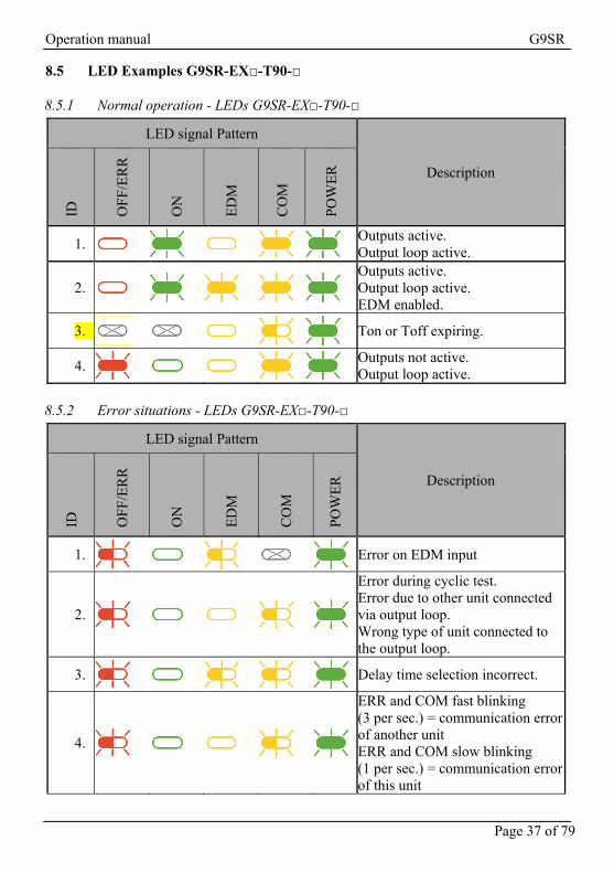
8.5 LED Examples G9SR-EX□-T90-□
8.5.1 Normal operation - LEDs G9SR-EX□-T90-□
LED signal Pattern
Description
ID
OF
F/E
RR
ON
ED
M
CO
M
PO
WE
R
1.
Outputs active. Output loop active.
2.
Outputs active. Output loop active. EDM enabled.
3.
Ton or Toff expiring.
4.
Outputs not active. Output loop active.
8.5.2 Error situations - LEDs G9SR-EX□-T90-□
LED signal Pattern
Description
ID
OF
F/E
RR
ON
ED
M
CO
M
PO
WE
R
1.
Error on EDM input
2.
Error during cyclic test. Error due to other unit connected via output loop. Wrong type of unit connected to the output loop.
3.
Delay time selection incorrect.
4.
ERR and COM fast blinking (3 per sec.) = communication error of another unit ERR and COM slow blinking (1 per sec.) = communication error of this unit

Operation manual G9SR
Page 38 of 79
8.6 Terminal and signal names of the G9SR-EX□-T90-□
13 Relay Output 1.1 (NO) 23 Relay Output 2.1 (NO) 33 Relay Output 3.1 (NO) 44 Output Auxiliary (Status ) A1 Power Supply A2 Power Supply GND T32 EDM Input T41 Output Loop OUT 14 Relay Output 1.2 (NO) 24 Relay Output 2.2 (NO) 34 Relay Output 3.2 (NO) T42 Output Loop IN
Operation manual G9SR
Page 39 of 79
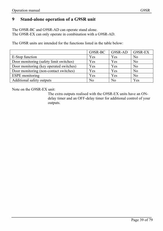
9 Stand-alone operation of a G9SR unit The G9SR-BC and G9SR-AD can operate stand alone. The G9SR-EX can only operate in combination with a G9SR-AD. The G9SR units are intended for the functions listed in the table below: G9SR-BC G9SR-AD G9SR-EX E-Stop function Yes Yes No Door monitoring (safety limit switches) Yes Yes No Door monitoring (key operated switches) Yes Yes No Door monitoring (non-contact switches) Yes Yes No ESPE monitoring Yes Yes No Additional safety outputs No No Yes Note on the G9SR-EX unit:
The extra outputs realised with the G9SR-EX units have an ON-delay timer and an OFF-delay timer for additional control of your outputs.
Operation manual G9SR
Page 40 of 79
9.1 Wiring examples stand-alone G9SR-BC
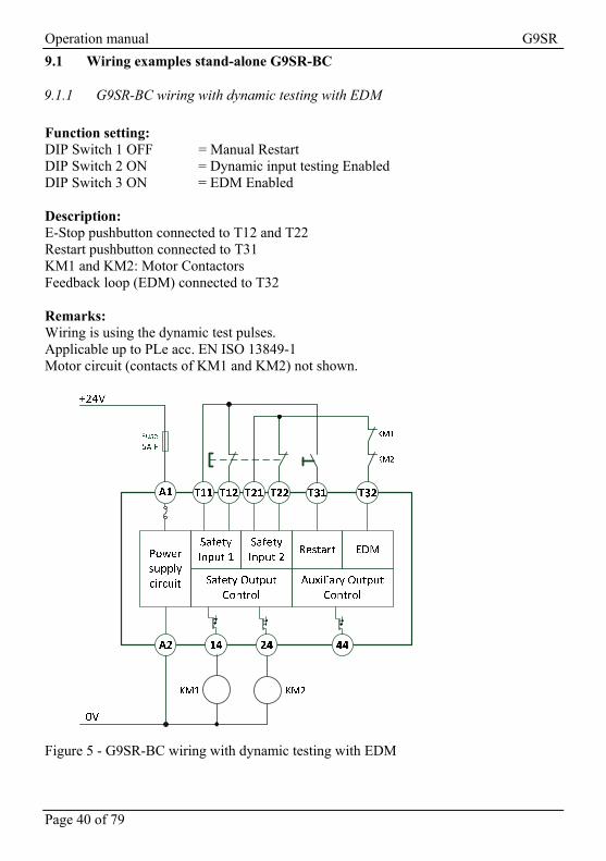
9.1.1 G9SR-BC wiring with dynamic testing with EDM
Function setting: DIP Switch 1 OFF = Manual Restart DIP Switch 2 ON = Dynamic input testing Enabled DIP Switch 3 ON = EDM Enabled Description: E-Stop pushbutton connected to T12 and T22 Restart pushbutton connected to T31 KM1 and KM2: Motor Contactors Feedback loop (EDM) connected to T32 Remarks: Wiring is using the dynamic test pulses. Applicable up to PLe acc. EN ISO 13849-1 Motor circuit (contacts of KM1 and KM2) not shown.
Figure 5 - G9SR-BC wiring with dynamic testing with EDM
Operation manual G9SR
Page 41 of 79
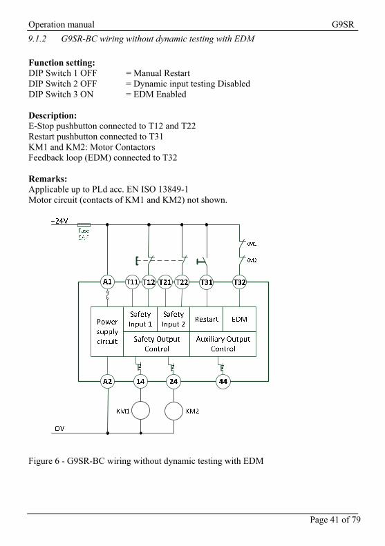
9.1.2 G9SR-BC wiring without dynamic testing with EDM
Function setting: DIP Switch 1 OFF = Manual Restart DIP Switch 2 OFF = Dynamic input testing Disabled DIP Switch 3 ON = EDM Enabled Description: E-Stop pushbutton connected to T12 and T22 Restart pushbutton connected to T31 KM1 and KM2: Motor Contactors Feedback loop (EDM) connected to T32 Remarks: Applicable up to PLd acc. EN ISO 13849-1 Motor circuit (contacts of KM1 and KM2) not shown.
Figure 6 - G9SR-BC wiring without dynamic testing with EDM

Operation manual G9SR
Page 42 of 79
9.1.3 G9SR-BC wiring with dynamic testing without EDM
Function setting: DIP Switch 1 OFF = Manual Restart DIP Switch 2 ON = Dynamic input testing Enabled DIP Switch 3 OFF = EDM Disabled Description: E-Stop pushbutton connected to T12 and T22 Restart pushbutton connected to T31 KM1 and KM2: Motor Contactors Remarks: Wiring is using the dynamic test pulses. Applicable up to PLd acc. EN ISO 13849-1 Motor circuit (contacts of KM1 and KM2) not shown.
Figure 7 - G9SR-BC wiring with dynamic testing without EDM

Operation manual G9SR
Page 43 of 79
9.1.4 G9SR-BC wiring without dynamic testing without EDM
Function setting: DIP Switch 1 OFF = Manual Restart DIP Switch 2 OFF = Dynamic input testing Disabled DIP Switch 3 OFF = EDM Disabled Description: E-Stop pushbutton connected to T12 and T22 Restart pushbutton connected to T31 KM1 and KM2: Motor Contactors Remarks: Applicable up to PLd acc. EN ISO 13849-1 Motor circuit (contacts of KM1 and KM2) not shown.
Figure 8 - G9SR-BC wiring without dynamic testing without EDM

Operation manual G9SR
Page 44 of 79
9.2 Stand-alone G9SR-AD
9.2.1 G9SR-AD wiring with dynamic testing with EDM
Function setting: DIP Switch 1 OFF = Manual Restart DIP Switch 2 ON = Dynamic input testing Enabled DIP Switch 3 ON = EDM Enabled Description: E-Stop pushbutton connected to T12 and T22 Restart pushbutton connected to T31 KM1 and KM2: Motor Contactors Feedback loop (EDM) connected to T32 Remarks: Wiring is using the dynamic test pulses. Applicable up to PLe acc. EN ISO 13849-1 Motor circuit (contacts of KM1 and KM2) not shown.
Figure 9 - G9SR-AD wiring with dynamic testing with EDM
Powersupplycircuit
SafetyInput 1
SafetyInput 2 Restart EDM
Safety Output Control
Auxiliary Output Control
IN Loop
OUT Loop
K1 K2
K1
K2
A1 T11 T12 T21 T22 T31 T32 13 23
T43
T41
T44
T42
A2 44 14 24
KM1
KM2
+24V
KM1 KM20V
Fuse1A F
Fuse5A F
Fuse5A F

Operation manual G9SR
Page 45 of 79
9.2.2 G9SR-AD wiring with dynamic testing without EDM
Function setting: DIP Switch 1 OFF = Manual Restart DIP Switch 2 ON = Dynamic input testing Enabled DIP Switch 3 OFF = EDM Disabled Description: E-Stop pushbutton connected to T12 and T22 Restart pushbutton connected to T31 KM1 and KM2: Motor Contactors Remarks: Wiring is using the dynamic test pulses. Applicable up to PLd acc. EN ISO 13849-1 Motor circuit (contacts of KM1 and KM2) not shown.
Figure 10 - G9SR-AD wiring with dynamic testing without EDM
Powersupplycircuit
SafetyInput 1
SafetyInput 2 Restart EDM
Safety Output Control
Auxiliary Output Control
IN Loop
OUT Loop
K1 K2
K1
K2
A1 T11 T12 T21 T22 T31 T32 13 23
T43
T41
T44
T42
A2 44 14 24
+24V
KM1 KM20V
Fuse1A F
Fuse5A F
Fuse5A F

Operation manual G9SR
Page 46 of 79
9.2.3 G9SR-AD wiring without dynamic testing with EDM
Function setting: DIP Switch 1 OFF = Manual Restart DIP Switch 2 OFF = Dynamic input testing Disabled DIP Switch 3 ON = EDM Enabled Description: E-Stop pushbutton connected to T12 and T22 Restart pushbutton connected to T31 KM1 and KM2: Motor Contactors Feedback loop (EDM) connected to T32 Remarks: Applicable up to PLd acc. EN ISO 13849-1 Motor circuit (contacts of KM1 and KM2) not shown.
Figure 11 - G9SR-AD wiring without dynamic testing with EDM
Powersupplycircuit
SafetyInput 1
SafetyInput 2 Restart EDM
Safety Output Control
Auxiliary Output Control
IN Loop
OUT Loop
K1 K2
K1
K2
A1 T11 T12 T21 T22 T31 T32 13 23
T43
T41
T44
T42
A2 44 14 24
KM1
KM2
+24V
KM1 KM20V
Fuse1A F
Fuse5A F
Fuse5A F

Operation manual G9SR
Page 47 of 79
9.2.4 G9SR-AD wiring without dynamic testing without EDM
Function setting: DIP Switch 1 OFF = Manual Restart DIP Switch 2 OFF = Dynamic input testing Disabled DIP Switch 3 OFF = EDM Disabled Description: E-Stop pushbutton connected to T12 and T22 Restart pushbutton connected to T31 KM1 and KM2: Motor Contactors Remarks: Applicable up to PLd acc. EN ISO 13849-1 Motor circuit (contacts of KM1 and KM2) not shown.
Figure 12 - G9SR-AD wiring without dynamic testing without EDM
Powersupplycircuit
SafetyInput 1
SafetyInput 2 Restart EDM
Safety Output Control
Auxiliary Output Control
IN Loop
OUT Loop
K1 K2
K1
K2
A1 T11 T12 T21 T22 T31 T32 13 23
T43
T41
T44
T42
A2 44 14 24
+24V
KM1 KM20V
Fuse1A F
Fuse5A F
Fuse5A F

Operation manual G9SR
Page 48 of 79
10 Combining G9SR units The G9SR-AD□-□ unit can be combined with G9SR-BC□-□ and G9SR-EX□-T90-□ units. Combinations possible are:
1) Extending a G9SR-AD with up to two G9SR-BC to create an input loop. See also § 10.1 Input loop on page 49
2) Extending a G9SR-AD with up to three G9SR-EX to create an output loop. See also § 10.2 Output loop on page 50
3) Extending a G9SR-AD with up to two G9SR-BC plus up to three G9SR-EX. This creates an input loop and an output loop. See also § 10.3 Input loop and Output loop on page 51
Caution! Use a single power supply for AD and EX units. For BC units separate power supplies can be used connecting the 0V of all power supplies together. Below an example of G9SR system with multi power supplies connections
T42 T41
A1 A2 A1 A2
T43 T44 T42 T41
+ - + - + -
A1 A2 A1 A2
T32 14 T32 14
A1 A2 A1 A2
T42 T41 T42 T41
Max 20 mt.
Max 20 mt.Common 0V

Operation manual G9SR
Page 49 of 79
10.1 Input loop
An input loop increases the number of safety inputs.
G9SR-AD□-□ units use terminals T43 and T44 for the Input loop. G9SR-BC□-□ units use terminals T32 (EDM input) and 14.
Connect the units according to following wiring schematic.
Caution! Maximum cable length for each wire of the Input loop is 20 meters.
Caution! Maximum cable impedance for the safety input circuit must be less than 250 ohm.
Caution! When the G9SR-BC is operating as a safety input in an input loop configuration, the two output terminals "13" and “14" cannot be used to drive additional loads. Make sure there is no load connected to these two terminals when the unit is in an input loop.

Operation manual G9SR
Page 50 of 79
10.2 Output loop
An output loop increases the number of safety outputs available.
G9SR-AD□-□ units use terminals T41 and T42 for the Output loop. G9SR-EX□-□ units use terminals T41 and T42 for the Output loop.
Connect 1, 2 or 3 G9SR-EX□-T90-□ units according to following wiring schematic:
Caution! Maximum cable length for each wire of the Output loop is 2 meters.

Operation manual G9SR
Page 51 of 79
10.3 Input loop and Output loop
The maximum allowable system configuration is a G9SR-AD unit extended with a maximum of two G9SR-BC units as additional safety inputs and three G9SR-EX units as additional safety outputs.
Figure 13 - Maximum configuration This configuration shows: * three safety inputs - two on the G9SR-BCs - one on the G9SR-AD * one safety output with two NO contacts on the G9SR-AD * three safety outputs with three NO contacts on the G9SR-Exs
Caution! Maximum cable length for Input loop is 20 meters. Maximum cable length for Output loop is 2 meters. The maximum cable length impedance for the safety input circuit must be lower than 250 ohm.

Operation manual G9SR
Page 52 of 79
11 Appendix A: Wiring examples
11.1 Wiring examples G9SR-BC□-□ unit
11.1.1 G9SR-BC□-□ in E-stop application up to PLe
Settings G9SR-BC:
Manual Restart Dynamic input testing Enabled EDM Enabled Aux inverted
Dip switch settings: 1 2 3 4 5 6 7 8 OFF ON ON OFF OFF OFF OFF OFF Description: E-Stop pushbutton connected to T12 and T22 Restart pushbutton connected to T31 KM1 and KM2: Motor Contactors Feedback loop (EDM) connected to T32 Remarks: This setup can also be used with safety limit switches and key operated door switches. For door and gate monitoring applications please consider the requirements from ISO 14119. Wiring is using the dynamic test pulses. Applicable up to PLe acc. EN ISO 13849-1 (electrical system). Motor circuit (contacts of KM1 and KM2) not shown.

Operation manual G9SR
Page 53 of 79
Figure 14 - G9SR-BC□-□ in E-stop application up to PLe Note: Ensure the dip switch settings of your G9SR-BC are according to
the requirements of your application.
See also § 6.3 Dip switches and functions of G9SR-BC□-□ on page 20.

Operation manual G9SR
Page 54 of 79
11.1.2 G9SR-BC□-□ in E-Stop application up to PLd
Settings G9SR-BC:
Manual Restart enabled EDM enabled Dynamic Input Test disabled Aux inverted
Dip switch settings: 1 2 3 4 5 6 7 8 OFF OFF ON OFF OFF OFF OFF OFF Description: E-Stop pushbutton connected to T12 and T22 Restart pushbutton connected to T31 KM1 and KM2: Motor Contactors Feedback loop (EDM) connected to T32 Remarks: This setup can also be used with safety limit switches and key operated door switches. For door and gate monitoring applications please consider the requirements from ISO 14119. Applicable up to PLd acc. EN ISO 13849-1 (electrical system). Motor circuit (contacts of KM1 and KM2) not shown.

Operation manual G9SR
Page 55 of 79
Figure 15 - G9SR-BC□-□ in E-Stop application up to PLd Note: Ensure the dip switch settings of your G9SR-BC are according to
the requirements of your application.
See also § 6.3 Dip switches and functions of G9SR-BC□-□ on page 20.

Operation manual G9SR
Page 56 of 79
11.1.3 G9SR-BC□-□ for door interlocking up to PLe with F3S-TGR-N__C
Settings G9SR-BC:
Manual Restart enabled EDM enabled Dynamic Input Test enabled Aux inverted
Dip switch settings: 1 2 3 4 5 6 7 8 OFF ON ON OFF OFF OFF OFF OFF Description: Non-contact switch connected to T12 and T22 Restart pushbutton connected to T31 KM1 and KM2: Motor Contactors Feedback loop (EDM) connected to T32 Remarks: This setup can also be used with safety limit switches and key operated door switches. For door and gate monitoring applications please consider the requirements from ISO 14119. Wiring is using the dynamic test pulses. Applicable up to PLe acc. EN ISO 13849-1 (electrical system). Motor circuit (contacts of KM1 and KM2) not shown.

Operation manual G9SR
Page 57 of 79
Powersupplycircuit
SafetyInput 1
SafetyInput 2 Restart EDM
Safety Output Control
Auxiliary Output Control
T32T31T22T21T12A1
A2 14 24 44
KM1 KM2
T11
KM1
KM2
+24V
0V
Fuse5A F
blue
whitegreenblack
yellow
red
Figure 16 - G9SR-BC□-□ for door interlocking up to PLe with F3S-TGR-N__C Note: Ensure the dip switch settings of your G9SR-BC are according to
the requirements of your application.
See also § 6.3 Dip switches and functions of G9SR-BC□-□ on page 20.

Operation manual G9SR
Page 58 of 79
11.1.4 G9SR-BC□-□ for door interlocking up to PLd with F3S-TGR-N__C
Settings G9SR-BC:
Manual Restart enabled EDM enabled Dynamic Input Test disabled Aux inverted
Dip switch settings: 1 2 3 4 5 6 7 8 OFF OFF ON OFF OFF OFF OFF OFF Description: Non-contact switch connected to T12 and T22 Restart pushbutton connected to T31 KM1 and KM2: Motor Contactors Feedback loop (EDM) connected to T32 Remarks: This setup can also be used with safety limit switches and key operated door switches. For door and gate monitoring applications please consider the requirements from ISO 14119. Applicable up to PLd acc. EN ISO 13849-1 (electrical system). Motor circuit (contacts of KM1 and KM2) not shown.

Operation manual G9SR
Page 59 of 79
Powersupplycircuit
SafetyInput 1
SafetyInput 2 Restart EDM
Safety Output Control
Auxiliary Output Control
T32T31T22T21T12A1
A2 14 24 44
KM1 KM2
T11
KM1
KM2
+24V
0V
Fuse5A F
blue
whitegreenblack
yellow
red
Figure 17 - G9SR-BC□-□ for door interlocking up to PLd with F3S-TGR-N__C Note: Ensure the dip switch settings of your G9SR-BC are according to
the requirements of your application.
See also § 6.3 Dip switches and functions of G9SR-BC□-□ on page 20.

Operation manual G9SR
Page 60 of 79
11.1.5 G9SR-BC□-□ with Safety Sensors in applications up to PLe (F3S-TGR-CL)
Settings G9SR-BC:
Manual Restart enabled EDM enabled Dynamic Input Test disabled Aux inverted
Dip switch settings: 1 2 3 4 5 6 7 8 OFF OFF ON OFF OFF OFF OFF OFF Description: Safety Sensor connected to T12 and T22 Restart pushbutton connected to T31 KM1 and KM2: Motor Contactors Feedback loop (EDM) connected to T32 Remarks: This setup can also be used for all sensors with solid state safety outputs Applicable up to PLe acc. EN ISO 13849-1 (electrical system). Motor circuit (contacts of KM1 and KM2) not shown.

Operation manual G9SR
Page 61 of 79
Figure 18 - G9SR-BC□-□ with Safety Sensors in applications up to PL=e (F3S-TGR-CL) Note: Ensure the dip switch settings of your G9SR-BC are according to
the requirements of your application.
See also § 6.3 Dip switches and functions of G9SR-BC□-□ on page 20.

Operation manual G9SR
Page 62 of 79
11.2 Wiring examples G9SR-AD□-□ unit
11.2.1 G9SR-AD□-□ in E-Stop application up to PLe
Settings G9SR-AD:
Manual Restart enabled EDM enabled Dynamic Input Test enabled
Dip switch settings: 1 2 3 4 5 6 7 8 OFF ON ON OFF OFF OFF OFF OFF Description: E-Stop pushbutton connected to T12 and T22 Restart pushbutton connected to T31 KM1 and KM2: Motor Contactors Feedback loop (EDM) connected to T32 Remarks: This setup can also be used with safety limit switches and key operated door switches. For door and gate monitoring applications please consider the requirements from ISO 14119. Wiring is using the dynamic test pulses. Applicable up to PLe acc. EN ISO 13849-1 (electrical system). Motor circuit (contacts of KM1 and KM2) not shown.

Operation manual G9SR
Page 63 of 79
Figure 19 - G9SR-AD□-□ in E-Stop application up to PLe Note: Ensure the dip switch settings of your G9SR-AD unit are
according to the requirements of your application.
See also § 7.3 Dip switches and functions of G9SR-AD□-□ on page 27.
Powersupplycircuit
SafetyInput 1
SafetyInput 2 Restart EDM
Safety Output Control
Auxiliary Output Control
IN Loop
OUT Loop
K1 K2
K1
K2
A1 T11 T12 T21 T22 T31 T32 13 23
T43
T41
T44
T42
A2 44 14 24
KM1
KM2
+24V
KM1 KM20V
Fuse1A F
Fuse5A F
Fuse5A F

Operation manual G9SR
Page 64 of 79
11.2.2 G9SR-AD□-□ in E-Stop application up to PLd
Settings G9SR-AD:
Manual Restart enabled EDM enabled Dynamic Input Test disabled
Dip switch settings: 1 2 3 4 5 6 7 8 OFF OFF ON OFF OFF OFF OFF OFF Description: E-Stop pushbutton connected to T12 and T22 Restart pushbutton connected to T31 KM1 and KM2: Motor Contactors Feedback loop (EDM) connected to T32 Remarks: This setup can also be used with safety limit switches and key operated door switches. For door and gate monitoring applications please consider the requirements from ISO 14119. Wiring is using the dynamic test pulses. Applicable up to PLd acc. EN ISO 13849-1 (electrical system). Motor circuit (contacts of KM1 and KM2) not shown.

Operation manual G9SR
Page 65 of 79
Figure 20 - G9SR-AD□-□ in E-Stop application up to PLd Note: Ensure the dip switch settings of your G9SR-AD unit are
according to the requirements of your application.
See also § 7.3 Dip switches and functions of G9SR-AD□-□ on page 27.
Powersupplycircuit
SafetyInput 1
SafetyInput 2 Restart EDM
Safety Output Control
Auxiliary Output Control
IN Loop
OUT Loop
K1 K2
K1
K2
A1 T11 T12 T21 T22 T31 T32 13 23
T43
T41
T44
T42
A2 44 14 24
KM1
KM2
+24V
KM1 KM20V
Fuse1A F
Fuse5A F
Fuse5A F

Operation manual G9SR
Page 66 of 79
11.2.3 G9SR-AD□-□ with door interlocking up to PLe with F3S-TGR-N__C
Settings G9SR-AD:
Manual Restart enabled EDM enabled Dynamic Input Test enabled
Dip switch settings: 1 2 3 4 5 6 7 8 OFF ON ON OFF OFF OFF OFF OFF Description: Non-contact switch connected to T12 and T22 Restart pushbutton connected to T31 KM1 and KM2: Motor Contactors Feedback loop (EDM) connected to T32 Remarks: This setup can also be used with safety limit switches and key operated door switches. For door and gate monitoring applications please consider the requirements from ISO 14119. Wiring is using the dynamic test pulses. Applicable up to PLe acc. EN ISO 13849-1 (electrical system). Motor circuit (contacts of KM1 and KM2) not shown.

Operation manual G9SR
Page 67 of 79
Figure 21 - G9SR-AD□-□ with door interlocking up to PLe with F3S-TGR-N__C Note: Ensure the dip switch settings of your G9SR-AD unit are
according to the requirements of your application.
See also § 7.3 Dip switches and functions of G9SR-AD□-□ on page 27.
Powersupplycircuit
SafetyInput 1
SafetyInput 2 Restart EDM
Safety Output Control
Auxiliary Output Control
IN Loop
OUT Loop
K1 K2
K1
K2
A1 T11 T12 T21 T22 T31 T32 13 23
T43
T41
T44
T42
A2 44 14 24
KM1
KM2
+24V
KM1 KM20V
Fuse1A F Fuse
5A FFuse5A F
blue
whitegreenblack
yellow
red
Actu
ator
F3S-
TGR-
N__C

Operation manual G9SR
Page 68 of 79
11.2.4 G9SR-AD□-□ with door interlocking up to PLd with F3S-TGR-N__C
Settings G9SR-AD:
Manual Restart enabled EDM enabled Dynamic Input Test disabled
Dip switch settings: 1 2 3 4 5 6 7 8 OFF OFF ON OFF OFF OFF OFF OFF Description: Non contact switch connected to T12 and T22 Restart pushbutton connected to T31 KM1 and KM2: Motor Contactors Feedback loop (EDM) connected to T32 Remarks: This setup can also be used with safety limit switches and key operated door switches. For door and gate monitoring applications please consider the requirements from ISO 14119. Applicable up to PLd acc. EN ISO 13849-1 (electrical system). Motor circuit (contacts of KM1 and KM2) not shown.

Operation manual G9SR
Page 69 of 79
Figure 22 - G9SR-AD□-□ with door interlocking up to PLd with F3S-TGR-N__C Note: Ensure the dip switch settings of your G9SR-AD unit are
according to the requirements of your application.
See also § 7.3 Dip switches and functions of G9SR-AD□-□ on page 27.
Powersupplycircuit
SafetyInput 1
SafetyInput 2 Restart EDM
Safety Output Control
Auxiliary Output Control
IN Loop
OUT Loop
K1 K2
K1
K2
A1 T11 T12 T21 T22 T31 T32 13 23
T43
T41
T44
T42
A2 44 14 24
KM1
KM2
+24V
KM1 KM20V
Fuse1A F Fuse
5A FFuse5A F
blue
whitegreenblack
yellow
red
Actu
ator
F3S-
TGR-
N__C
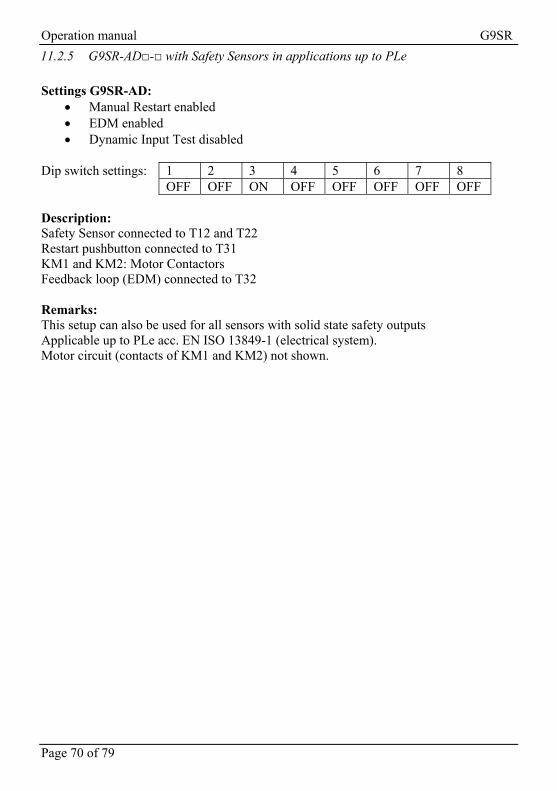
Operation manual G9SR
Page 70 of 79
11.2.5 G9SR-AD□-□ with Safety Sensors in applications up to PLe
Settings G9SR-AD:
Manual Restart enabled EDM enabled Dynamic Input Test disabled
Dip switch settings: 1 2 3 4 5 6 7 8 OFF OFF ON OFF OFF OFF OFF OFF Description: Safety Sensor connected to T12 and T22 Restart pushbutton connected to T31 KM1 and KM2: Motor Contactors Feedback loop (EDM) connected to T32 Remarks: This setup can also be used for all sensors with solid state safety outputs Applicable up to PLe acc. EN ISO 13849-1 (electrical system). Motor circuit (contacts of KM1 and KM2) not shown.

Operation manual G9SR
Page 71 of 79
Figure 23 - G9SR-AD□-□ with Safety Sensors in applications up to PLe Note: Ensure the dip switch settings of your G9SR-AD are according to
the requirements of your application.
See also § 7.3 Dip switches and functions of G9SR-AD□-□ on page 27.
Powersupplycircuit
SafetyInput 1
SafetyInput 2 Restart EDM
Safety Output Control
Auxiliary Output Control
IN Loop
OUT Loop
K1 K2
K1
K2
A1 T11 T12 T21 T22 T31 T32 13 23
T43
T41
T44
T42
A2 44 14 24
KM1
KM2
+24V
KM1 KM20V
Fuse1A F Fuse
5A FFuse5A F
blue
graypink
brown
F3S-
TGR-
CLtr
ansm
ier
F3S-
TGR-
CLre
ceiv
erwhite
blue
brown

Operation manual G9SR
Page 72 of 79
11.3 Wiring examples G9SR-AD□-□ unit with input loop and output loop
11.3.1 Machine example
Figure 24 – Machine example
11.3.2 Description of the safety related control functions in this application
1. When the E-Stop is pushed, the winder stops immediately and the door is
locked for another 30s. 2. When the Light Curtain detects a person, the winder stops immediately and the
door is locked for another 30s. 3. The door is mechanically locked by a door locking switch.
Unlocking is provided by electrical signal. 4. When the door is not locked, machine startup must be prevented.

Operation manual G9SR
Page 73 of 79
11.3.3 Solution - block diagram
The solution is using 2 G9SR-BC, 1 G9SR-AD and 1 G9SR-EX
14.3.4 Function settings and DIP switch settings
G9SR-BC1: Dynamic input test Enabled EDM Disabled Input loop Enabled G9SR-BC2: Dynamic Input test Enabled EDM Disabled Input loop Enabled G9SR-AD Dynamic Input test Disabled Manual Restart EDM Enabled Input loop Enabled Output loop Enabled G9SR-EX: EDM Enabled Output loop Enabled OFF-Delay time = 30s

Operation manual G9SR
Page 74 of 79
SW1 SW2 SW3 SW4 SW5 SW6 SW7 SW8 G9SR-BC1 ON ON OFF ON OFF OFF OFF OFF G9SR-BC2 ON ON OFF ON OFF OFF OFF OFF G9SR-AD OFF OFF ON ON ON OFF ON OFF SW1 SW2 SW3 SW4 G9SR-EX 0 B 0 B
Note: Ensure the dip switch settings of all G9SR-units are according to
the requirements of your application. See also § 6.3 Dip switches and functions of G9SR-BC□-□ on page 20 § 7.3 Dip switches and functions of G9SR-AD□-□ on page 27 § 8.3 Rotary switch functions of G9SR-EX□-T90-□ on page 34

Operation manual G9SR
Page 75 of 79
Figure 25 – Wiring diagram for machine example
Powersupplycircuit
SafetyInput 1
SafetyInput 2 Restart EDM
Safety Output Control
Auxiliary Output Control
IN Loop
OUT Loop
K1 K2
K1
K2
A1 T11 T12 T21 T22 T31 T32 13 23
T43
T41
T44
T42
A2 44 14 24
KM1
KM2
KM1 KM2
Fuse1A F Fuse
5A FFuse5A F
blue
graypink
brown
F3S-
TGR-
CLtr
ansm
ier
F3S-
TGR-
CLre
ceiv
er
white
blue
brown
Powersupplycircuit
SafetyInput 1
SafetyInput 2 Restart EDM
Safety Output Control
Auxiliary Output Control
T32T31T22T21T12A1
A2 14 24 44
T11
+24V
Fuse5A F
Powersupplycircuit
SafetyInput 1
SafetyInput 2 Restart EDM
Safety Output Control
Auxiliary Output Control
T32T31T22T21T12A1
A2 14 24 44
T11
Fuse5A F
Powersupplycircuit
EDM
Safety Output Control
Auxiliary Output Control
OUT Loop
K1 K2
K1
K2
A1 T32 13 23
T41
T42
A2 44 14 24
33
34
TimerControl
G9SR-BC1
0V
G9SR-BC2
G9SR-AD
Fuse5A F
Fuse1A F
G9SR-EX
Door Locking Solenoid Control Contactor
DSCC1
DSCC1
DoorLockingSwitch
KM1
KM2
M
Winder

Operation manual G9SR
Page 76 of 79
My notes:

Operation manual G9SR
Page 77 of 79
12 Appendix B: Logging of test results MONTH: SYSTEM:
Date Performed with good results. (OFF Test / ON Test / Both)
Technicians Signature:
Remarks:
1 2 3 4 5 6 7 8 9
10 11 12 13 14 15 16 17 18 19 20 21 22 23 24 25 26 27 28 29 30 31

Operation manual G9SR
Page 78 of 79
Logging of test results MONTH: SYSTEM:
Date Performed with good results. (OFF Test / ON Test / Both)
Technicians Signature:
Remarks:
1 2 3 4 5 6 7 8 9
10 11 12 13 14 15 16 17 18 19 20 21 22 23 24 25 26 27 28 29 30 31

Operation manual G9SR
Page 79 of 79
My notes:

MANUFACTURER Omron Europe B.V. Zilverenberg 2 5234 GM 's-Hertogenbosch THE NETHERLANDS Tel: +31 (0) 73 6481811 Fax: +31 (0) 73 6444100 GENERAL AGENCY OMRON EUROPE B.V. Wegalaan 67-69 NL-2132 JD Hoofddorp THE NETHERLANDS Tel.: +31 (0) 23 5681300 Fax: +31 (0) 23 5681388 www. industrial.omron.eu
Cat. No. J12E-EN-04 Note: Specifications subject to change without notice.
Authorized Distributor:
Printed in Europe