
Operation Manual - jpn.surugaseiki.com · ※The contents other than listed in this operation...
15
Operation Manual Ver 1.3 Suruga Seiki.Co.Ltd OST Division
Transcript of Operation Manual - jpn.surugaseiki.com · ※The contents other than listed in this operation...

Operation Manual
Ver 1.3
Suruga Seiki.Co.Ltd
OST Division
2
INDEX
1.Introduction
1.1 Main function ··································································· P.3
1.2 Before use ········································································ P.3
1.3 Safety instruction ································································ P.4
1.4 Part names and functions ···················································· P.6
1.5 Option ·············································································· P.7
2.Operation method
2.1 Configuration and connection ·················································· P.8
2.2 Measurement procedure ····················································· P.9
2.3 Measurement examples ······················································ P.11
3.Others
3.1 Trouble shooting ································································ P.12
3.2 Specification ········································································ P.13
3.3 Warranty and after service ·················································· P.14
Thank you for purchasing our products.
For proper use, please read the instruction manual before usage carefully.
After reading, keep it at the place where it could be found all the time.
3
1.Introduction
1.1 Main function
H100 series is measuring device to project angle displacement amount of laser beam on to a screen.
Applied laser beam is RED Laser Diode of wavelength 650mn, which performs excellent in directional
characteristic and safety use.
Aperturefunctionenablesvariabilityofcorediameterofthelaseralongwithmeasuringobjects. Laser intensity
adjustment toward CCD is available.
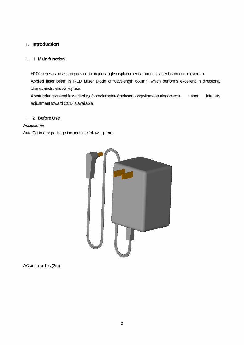
1.2 Before Use
Accessories
Auto Collimator package includes the following item:
AC adaptor 1pc (3m)
4
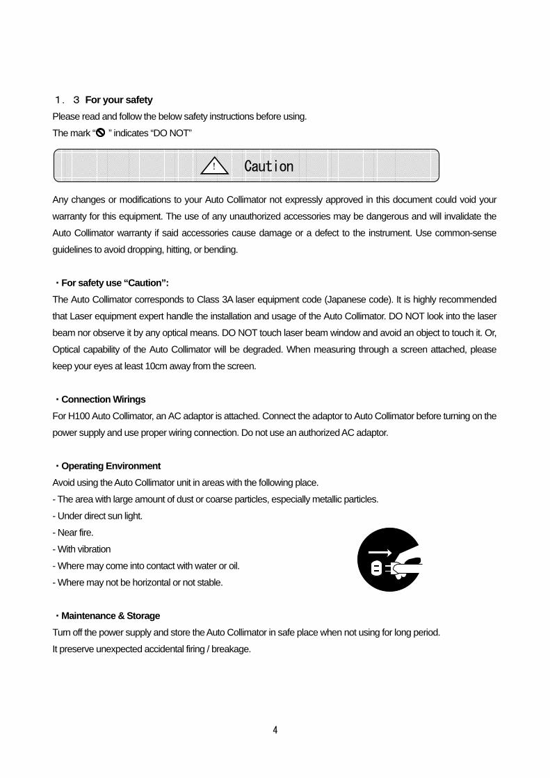
1.3 For your safety
Please read and follow the below safety instructions before using.
The mark “ ” indicates “DO NOT”
Any changes or modifications to your Auto Collimator not expressly approved in this document could void your
warranty for this equipment. The use of any unauthorized accessories may be dangerous and will invalidate the
Auto Collimator warranty if said accessories cause damage or a defect to the instrument. Use common-sense
guidelines to avoid dropping, hitting, or bending.
・For safety use “Caution”:
The Auto Collimator corresponds to Class 3A laser equipment code (Japanese code). It is highly recommended
that Laser equipment expert handle the installation and usage of the Auto Collimator. DO NOT look into the laser
beam nor observe it by any optical means. DO NOT touch laser beam window and avoid an object to touch it. Or,
Optical capability of the Auto Collimator will be degraded. When measuring through a screen attached, please
keep your eyes at least 10cm away from the screen.
・Connection Wirings
For H100 Auto Collimator, an AC adaptor is attached. Connect the adaptor to Auto Collimator before turning on the
power supply and use proper wiring connection. Do not use an authorized AC adaptor.
・Operating Environment
Avoid using the Auto Collimator unit in areas with the following place.
- The area with large amount of dust or coarse particles, especially metallic particles.
- Under direct sun light.
- Near fire.
- With vibration
- Where may come into contact with water or oil.
- Where may not be horizontal or not stable.
・Maintenance & Storage
Turn off the power supply and store the Auto Collimator in safe place when not using for long period.
It preserve unexpected accidental firing / breakage.
Caution !

5
・ Electric supply
This Auto Collimator is AC100 power system (AC100V). When use outside of Japan, please prepare proper
voltage converter for your county electric supply. Or contact to us.
・Disassemble / Modification
Do not disassemble, modify or make improper repairs to the Auto Collimator.
It might cause unexpected accident. It is dangerous.
If you have questions, please contact with us.
・Repair needs
Please unplug the unit immediately and contact local distributor or Suruga Seiki / OST Overseas Sales office, if
any of the following occurs:
- The unit gives out an unusual sound; smell or smoke appears
- When the power code is frayed or damaged
- Water has spilled into the main unit
- Unit has been dropped or its outer shell has become damaged or cracked.
Please refer to page 15 for contact information.
Caution !

6
1.4 Explanation of Parts and Functions
Figure 1. Mainbody (Screen & CCD type)
①DC Jack
Connection with an attached AC adaptor.
②Laser beam window
③C-mount for CCD camera attachment.
Screen & CCD type (H100-SC), CCD type (H100-C) can attach CCD camera onto C-mount. CCD camera
can not be attached to Screen type (H100-S).
①
②
③
④
⑤
⑥

7
④Projection Screen
Screen & CCD tye (H100-SC) and Screen type (H100-S) can be measured on the projection screen.
⑤Variable Aperture
Core diameter of Laser beam is changeable (φ1, 2, 3, 4).
⑥Laser Intensity control
Laser Intensity adjustment is available. Turing knob is optional.
1.5 Options
Option description Model # Remarks
CCD camera with
power supply.
1/3 inch VXC-ES30SET
1/2 inch VXC-ES50SET
2/3 inch VXC-ST70SET
Monitor 5.5 inch TFT LCD Please ask us 10 inch CRT mono VWM-1510A
Line generator VOPVG-30 2 axis tilt stage HB10
Mount HA10
Optical Parallel HS-0 φ30,t=10
One side AL coating Parallelism= <5”
Precision wedge plate
1” HS-100 □40,t=10 Parallelism = <±10” 0.5” HS-050
0.25” HS-025 12’(0.2”) HS-020
8
2.Operation procedure
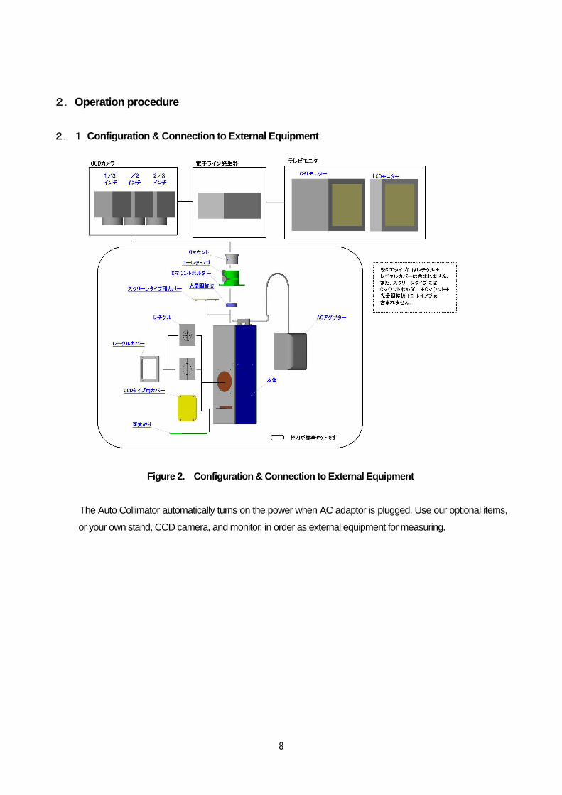
2.1 Configuration & Connection to External Equipment
Figure 2. Configuration & Connection to External E quipment
The Auto Collimator automatically turns on the power when AC adaptor is plugged. Use our optional items,
or your own stand, CCD camera, and monitor, in order as external equipment for measuring.
9
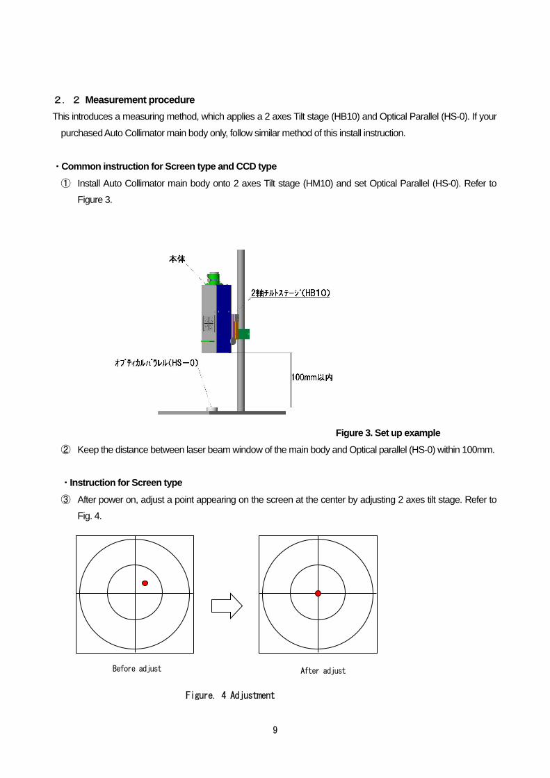
2.2 Measurement procedure
This introduces a measuring method, which applies a 2 axes Tilt stage (HB10) and Optical Parallel (HS-0). If your
purchased Auto Collimator main body only, follow similar method of this install instruction.
・Common instruction for Screen type and CCD type
① Install Auto Collimator main body onto 2 axes Tilt stage (HM10) and set Optical Parallel (HS-0). Refer to
Figure 3.
Figure 3. Set up example
② Keep the distance between laser beam window of the main body and Optical parallel (HS-0) within 100mm.
・Instruction for Screen type
③ After power on, adjust a point appearing on the screen at the center by adjusting 2 axes tilt stage. Refer to
Fig. 4.
Figure. 4 Adjustment
Before adjust After adjust

10
④ After the adjustment, place the object and measure.
When measuring by using a built-in screen of main body, the outer
circle becomes the maximum core angle of measuring range, and
the inner circle becomes a half (1/2) of maximum core. One scale
mark is one then (1/10) of the maximum core angle.
*Rad the center of laser diameter for measuring.
○Measuring Example
When using measuring range ±1°(H100-S100、H100-S100C) and it appears as Fig. 5, measuring
result show that approximately 0.6-inclination is observed.
⑤ Adjust laser intensity to the most visible level on a screen.
・Instruction for CCD Camera type
③Adjust the laser beam which is reflected by Optical Parallel
until it comes to the center of monitor screen. On the center
of the screen, display and match a cross line by using
Line Generator “VOPVG-30”. Then, place Precision Wedge
Plate, and display a circle with a radius that forms a distance
between the center of a cross line and the center of laser
diameter. This circle is to become an angle of the Precision
Wedge Plate.
Use it as a reference point for measuring. Refer Fig. 6 & 7.
*For detail instruction on displaying line, refer to an operation
manual of Line Generator VOPVG-30.
Max. range
1/2 of max range
Laser diameter
Figure 6.
Placing Precision Wedge Plate.
11
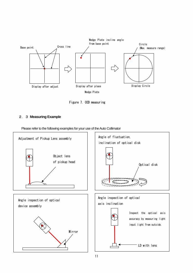
2.3 Measuring Example
Please refer to the following examples for your use of the Auto Collimator
Angle of fluctuation,
inclination of optical disk
Optical disk
Adjustment of Pickup Lens assembly
Object lens
of pickup head
Angle inspection of optical
axis inclination
Inspect the optical axis
accuracy by measuring light
input light from outside.
LD with lens
Angle inspection of optical
device assembly
Mirror
Display after adjust Display after place
Wedge Plate
Figure 7. CCD measuring
Display Circle
Cross line Circle
(Max. measure range) Base point
Wedge Plate incline angle
from base point

12
3.Others
3.1 Trouble Shooting Trouble
Possible Cause
Solution
Page
No power Power cable is unplugged Check the electric connection
―
No laser appears on Screen
Distance to object is too far Keep the distance to object within 100mm P. 9
Measuring object that is large than measuring range
Measure object within measuring object
―
Life time of laser beam is over Use new laser beam ―
Different measuring results from monitor and screen
Adjustment process is not completed
Redo adjustment process from beginning P. 9
Difficult to read laser beam
Reflectivity of object is low Adjust with variable aperture or attach a mirror to object
13
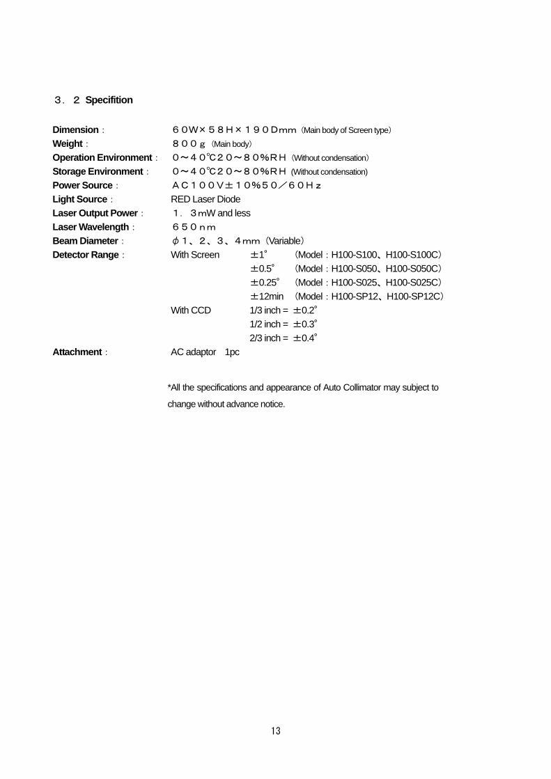
3.2 Specifition
Dimension : 60W×58H×190Dmm(Main body of Screen type)
Weight: 800g(Main body)
Operation Environment : 0~40℃20~80%RH(Without condensation)
Storage Environment : 0~40℃20~80%RH (Without condensation) Power Source : AC100V±10%50/60Hz Light Source : RED Laser Diode Laser Output Power : 1.3mW and less Laser Wavelength : 650nm Beam Diameter : φ1、2、3、4mm(Variable) Detector Range : With Screen ±1° (Model:H100-S100、H100-S100C)
±0.5° (Model:H100-S050、H100-S050C) ±0.25° (Model:H100-S025、H100-S025C) ±12min (Model:H100-SP12、H100-SP12C)
With CCD 1/3 inch = ±0.2° 1/2 inch = ±0.3° 2/3 inch = ±0.4°
Attachment : AC adaptor 1pc
*All the specifications and appearance of Auto Collimator may subject to
change without advance notice.
14
3.3 Warranty and Maintenace Service
●Warranty
Warranty period is one year from time of purchase. When contacting your Suruga Seiki distributor or our Overseas
Sales office, please refer to the serial number (8 digits) as indicated on the product label. Suruga Seiki will refer to
the date of purchase and registration.
The following conditions are not covered by the warranty.
- Failure to use the product properly as explained in the instruction manual, damage or injury caused by repair
or modification made by a person other than a qualified personnel of Suruga Seiki.
- Damage caused by breakage during shipping or transportation or faulty handling.
- Damage due to fire, gas, sea and sea wind, wrong electrical or battery voltage, earthquake, thunder, flood
and wind, and any other acts of nature.
- Damage or injury due to not following the proper procedures as indicated in the instruction manuals, not
adhering to the caution warnings as indicated in the instruction manuals.
●Maintenace Service
Please review th section on Trouble Shooting prior to requesting maintenance service. If the problem still persists,
please contact your local Suruga Seiki distributor for service.
《Within Warranty Period》
Suruga Seiki will repari free of charge and damage parts within warranty period except those reparis listed aboe as
out of warranty coverage.
《After Warranty Period》
Repairs made after the warranty period will require repair and parts charges.
●Warranty Period and Repair Parts
Warranty period for repairs is one year. Replacement parts are guaranteed for one year. Please contact your local
Suruga Seiki distributor for repairs and replacement parts during and after the warranty period
※The contents other than listed in this operation manual, Suruga
Seiki has no responsibility for the breakages.
15
For More Information Call to us:
SURUGA SEIKI CO., LTD. Overseas Section, OST Division
3F KonanYKBldg,2,4,12,Konan,Minato-ku, Tokyo, 108-0075 Japan
TEL : +81-3-6711-5014
FAX : +81-3-6711-5021
URL : http://www.suruga-ost.com/ E-mail : [email protected]
OST-D3160


