OPERATION, MAINTENANCE AND INSTALLATION MANUAL FOR · play it safe! operation, maintenance and...
50
PLAY IT SAFE! OPERATION, MAINTENANCE AND INSTALLATION MANUAL FOR VERTICAL RECYCLER BALER INCLUDING THESE MODELS: V-4830 V-4830HD V-6030LP V-6030 V-6030HD V-6042LP V-7230HD A DOVER INDUSTRIES COMPANY Marathon Equipment Co. OMI Manual No. 0003, Rev. 01/01 VERNON, AL - YERINGTON, NV - CLEARFIELD, PA LEEDS, AL - FAYETTE, AL
Transcript of OPERATION, MAINTENANCE AND INSTALLATION MANUAL FOR · play it safe! operation, maintenance and...

PLAY IT SAFE!
OPERATION, MAINTENANCEAND INSTALLATION MANUAL
FOR
VERTICAL RECYCLER BALER
INCLUDING THESE MODELS:
V-4830 V-4830HD V-6030LPV-6030 V-6030HD V-6042LP
V-7230HD
A DOVER INDUSTRIES COMPANY
Marathon Equipment Co. OMI Manual No. 0003, Rev. 01/01
VERNON, AL - YERINGTON, NV - CLEARFIELD, PALEEDS, AL - FAYETTE, AL
SECTION 1 - Operation
Introduction ................................................................. 1-1Pre-Operating Instructions ....................................... 1-2Controls
For HD and V-6030LP Units ................................ 1-3For V-6030 and V-4830 Units .............................. 1-4 For V6042LP Units .............................................. 1-5
Control Description ...................................................... 1-6Operating Instructions
Making A Bale - HD and LP Units ....................... 1-7Making a Bale - V-6030 and V-4830 ................... 1-8Bale Tie Off - V-6030HD, V-4830HD, V-7230HD 1-9
Diagram .......................................................... 1-10Bale Tie Off - V-6030LP ...................................... 1-11
Diagram .......................................................... 1-12Bale Tie Off - V-6042LP ...................................... 1-13
Diagram .......................................................... 1-14Bale Tie Off - V-4830 and V-6030 ...................... 1-15
Diagram .......................................................... 1-16Tie Slot Cleaning-Diagram ........................................ 1-17Decals ......................................................................... 1-18Decal Placement For Vertical Balers ........................... 1-20
SECTION 2 - Maintenance
Lock-Out & Tag-Out Instructions ............................ 2-1Supporting of Platen ................................................... 2-2Periodic Maintenance ................................................. 2-3Procedures
Pressure Setting .................................................. 2-4 Interlock Testing .................................................. 2-4Cylinder Removal ................................................ 2-5Cylinder Rebuilding ............................................ 2-6Limit Switch Adjustment ...................................... 2-6Warranty and Service on Motors ......................... 2-6Feed Gate Latch Adjustment ............................... 2-7
Principles of Operation ............................................... 2-8Baler Specifications..................................................... 2-10Timer Adjustment ....................................................... 2-11Charts ......................................................................... 2-12Parts List .....................................................................2-13Panel Box
For HD and LP Units ........................................... 2-14For V-6030 and V-4830 Units ............................. 2-15
CONTENTS
CONTENTS
SECTION 2 - Maintenance (continued)Power Unit
For 4830, 6030, 4830HD, 6030HD, & 7230HD ... 2-16For 6030LP ......................................................... 2-17For 6042LP ......................................................... 2-18
Hydraulic Schematic For Vertical Balers - Typical ................................ 2-19For V6042LP ....................................................... 2-20
Trouble-Shooting Chart ...............................................2-21
SECTION 3 - Installation
Off-Loading and Up-Ending Of Baler ......................... 3-1General Installation .................................................... 3-2Electrical Installation .................................................. 3-3Start-Up Instructions .................................................. 3-4
Copyright Marathon Equipment Company, January 2001.
1 OPERATION
INTRODUCTION
THANK YOU FOR PURCHASING A MARATHON VERTICAL BALER.
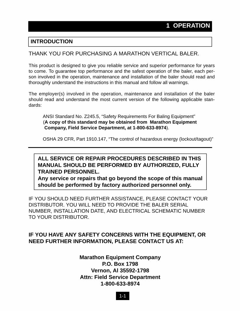
This product is designed to give you reliable service and superior performance for yearsto come. To guarantee top performance and the safest operation of the baler, each per-son involved in the operation, maintenance and installation of the baler should read andthoroughly understand the instructions in this manual and follow all warnings.
The employer(s) involved in the operation, maintenance and installation of the balershould read and understand the most current version of the following applicable stan-dards:
ANSI Standard No. Z245.5, “Safety Requirements For Baling Equipment” (A copy of this standard may be obtained from Marathon EquipmentCompany, Field Service Department, at 1-800-633-8974).
OSHA 29 CFR, Part 1910.147, “The control of hazardous energy (lockout/tagout)”
IF YOU SHOULD NEED FURTHER ASSISTANCE, PLEASE CONTACT YOURDISTRIBUTOR. YOU WILL NEED TO PROVIDE THE BALER SERIALNUMBER, INSTALLATION DATE, AND ELECTRICAL SCHEMATIC NUMBERTO YOUR DISTRIBUTOR.
IF YOU HAVE ANY SAFETY CONCERNS WITH THE EQUIPMENT, ORNEED FURTHER INFORMATION, PLEASE CONTACT US AT:
Marathon Equipment CompanyP.O. Box 1798
Vernon, Al 35592-1798Attn: Field Service Department
1-800-633-8974
1-1
ALL SERVICE OR REPAIR PROCEDURES DESCRIBED IN THIS MANUAL SHOULD BE PERFORMED BY AUTHORIZED, FULLY TRAINED PERSONNEL.Any service or repairs that go beyond the scope of this manual should be performed by factory authorized personnel only.
1 OPERATION
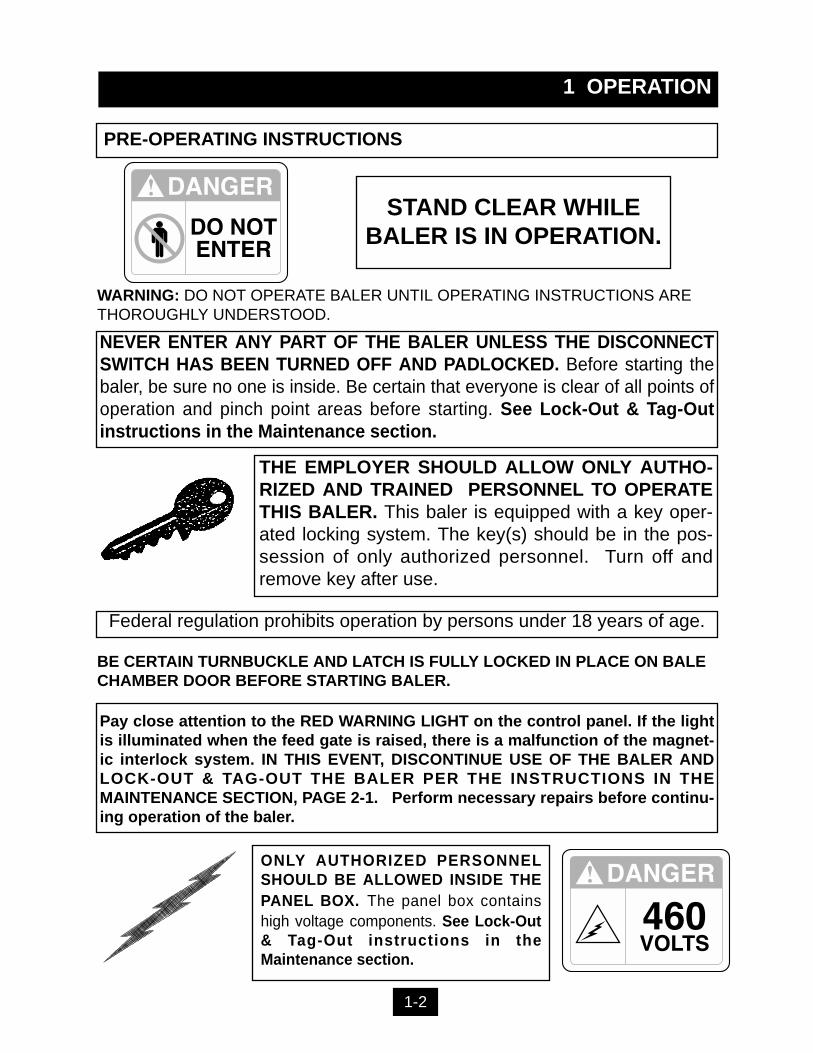
PRE-OPERATING INSTRUCTIONS
NEVER ENTER ANY PART OF THE BALER UNLESS THE DISCONNECTSWITCH HAS BEEN TURNED OFF AND PADLOCKED. Before starting thebaler, be sure no one is inside. Be certain that everyone is clear of all points ofoperation and pinch point areas before starting. See Lock-Out & Tag-Outinstructions in the Maintenance section.
THE EMPLOYER SHOULD ALLOW ONLY AUTHO-RIZED AND TRAINED PERSONNEL TO OPERATETHIS BALER. This baler is equipped with a key oper-ated locking system. The key(s) should be in the pos-session of only authorized personnel. Turn off andremove key after use.
Pay close attention to the RED WARNING LIGHT on the control panel. If the lightis illuminated when the feed gate is raised, there is a malfunction of the magnet-ic interlock system. IN THIS EVENT, DISCONTINUE USE OF THE BALER ANDLOCK-OUT & TAG-OUT THE BALER PER THE INSTRUCTIONS IN THEMAINTENANCE SECTION, PAGE 2-1. Perform necessary repairs before continu-ing operation of the baler.
ONLY AUTHORIZED PERSONNELSHOULD BE ALLOWED INSIDE THEPANEL BOX. The panel box containshigh voltage components. See Lock-Out& Tag-Out instructions in theMaintenance section.
BE CERTAIN TURNBUCKLE AND LATCH IS FULLY LOCKED IN PLACE ON BALECHAMBER DOOR BEFORE STARTING BALER.
STAND CLEAR WHILEBALER IS IN OPERATION.
WARNING: DO NOT OPERATE BALER UNTIL OPERATING INSTRUCTIONS ARETHOROUGHLY UNDERSTOOD.
1-2
Federal regulation prohibits operation by persons under 18 years of age.
1 OPERATION
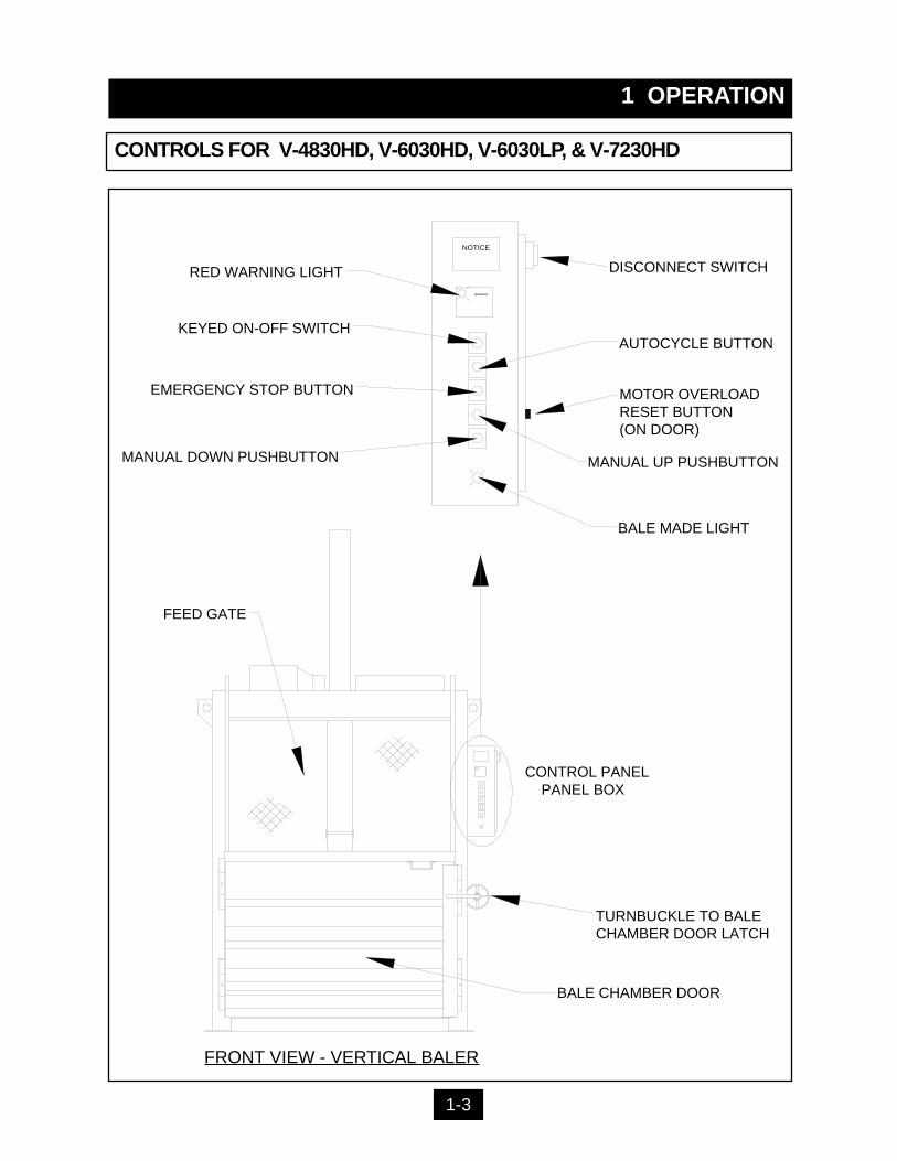
CONTROLS FOR V-4830HD, V-6030HD, V-6030LP, & V-7230HD
FRONT VIEW - VERTICAL BALER
MANUAL DOWN PUSHBUTTON
BALE MADE LIGHT
RED WARNING LIGHT
AUTOCYCLE BUTTONKEYED ON-OFF SWITCH
EMERGENCY STOP BUTTON
MANUAL UP PUSHBUTTON
MOTOR OVERLOADRESET BUTTON(ON DOOR)
DISCONNECT SWITCH
FEED GATE
CONTROL PANELPANEL BOX
TURNBUCKLE TO BALE CHAMBER DOOR LATCH
BALE CHAMBER DOOR
WARNING
NOTICE
1-3
1 OPERATION
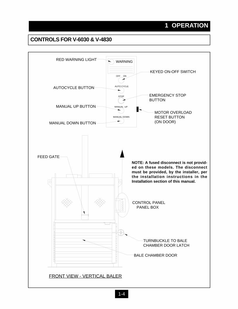
CONTROLS FOR V-6030 & V-4830
WARNING
STOP
MANUAL DOWN
MANUAL UP
AUTO CYCLE
OFF ON
RED WARNING LIGHT
KEYED ON-OFF SWITCH
AUTOCYCLE BUTTON
EMERGENCY STOPBUTTON
MOTOR OVERLOADRESET BUTTON(ON DOOR)
MANUAL UP BUTTON
MANUAL DOWN BUTTON
FEED GATE
TURNBUCKLE TO BALECHAMBER DOOR LATCH
BALE CHAMBER DOOR
CONTROL PANELPANEL BOX
NOTE: A fused disconnect is not provid-ed on these models. The disconnectmust be provided, by the installer, perthe installation instructions in theInstallation section of this manual.
FRONT VIEW - VERTICAL BALER
1-4
1 OPERATION
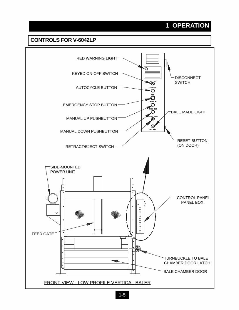
CONTROLS FOR V-6042LP
1-5
FRONT VIEW - LOW PROFILE VERTICAL BALER
RETRACT/EJECT SWITCH
SIDE-MOUNTEDPOWER UNIT
MANUAL DOWN PUSHBUTTON
BALE MADE LIGHT
RED WARNING LIGHT
AUTOCYCLE BUTTON
KEYED ON-OFF SWITCH
EMERGENCY STOP BUTTON
MANUAL UP PUSHBUTTON
RESET BUTTON(ON DOOR)
DISCONNECTSWITCH
FEED GATE
CONTROL PANELPANEL BOX
TURNBUCKLE TO BALE CHAMBER DOOR LATCH
BALE CHAMBER DOOR

ON-OFF (Keyed Selector Switch)Turning this switch to the ON position activates the other controls on the control station.The baler can not be operated unless the key is in the switch and the switch is in the ONposition. The purpose of this switch is to allow only authorized and trained personnel tooperate the baler. The key should be removed from the baler when not in use and shouldstay in the possession of only responsible and trained personnel.
EMERGENCY STOP (Red Mushroom Head Pushbutton)Depressing this button will stop the machine at any point in the cycle.
AUTOCYCLE (Green Pushbutton)The AUTOCYCLE button can be used only when the feed gate and bale door are closedand the keyswitch is in the ON position. Once depressed, the AUTOCYCLE button willcause the platen to move to the fully down position and back to the fully raised position(one complete cycle).
MANUAL UP (Black Pushbutton)This button will only start the baler with the keyswitch in the ON position. Depressing thebutton will raise the platen with the feed gate and bale door opened or closed. It is normallyused during bale ejection. It can also be used to interrupt the automatic cycle and raise theplaten should it become necessary. The MANUAL UP button is a “Hold To Run” control,causing the baler to stop when it is released. WARNING: STAY CLEAR OF MOVINGPARTS WHEN USING THE MANUAL UP BUTTON WITH THE FEED GATE OPEN.
MANUAL DOWN (Black Pushbutton)This button will only start the baler with the keyswitch in the ON position. Depressing thebutton will lower the platen only if the feed gate and bale door are closed. It can be used tointerrupt the automatic cycle and lower the platen should it become necessary. The MANU-AL DOWN button is a “Hold To Run” control, causing the baler to stop when it is released.
RED WARNING LIGHTThis light will warn the operator of a magnetic interlock switch malfunction. If the light is onand the feed gate is in the up position, there is a problem. Discontinue use of the baler.Turn off the baler and Lock-out and Tag-out per the instructions on page 2-1. Then call aqualified service person. The light SHOULD BE ON when the feed gate is in the down posi-tion.
BALE MADE LIGHT (Not included on V-6030 and V-4830 models)This light will come on if enough material has been compacted to make a complete bale.
RETRACT/EJECT (Spring-centered Switch) (USED ON THE V-6042LP ONLY) This spring-centered switch will eject the bale by means of a hydraulic ejector when theswitch is held to the EJECT position. When the button is held to the RETRACT position, theejector will retract. The MANUAL UP button must be depressed and held at the same timethe RETRACT/EJECT switch is used.
1 OPERATION
CONTROL DESCRIPTION
1.
2.
3.
4.
5.
6.
7.
8.
1-6
1 OPERATION
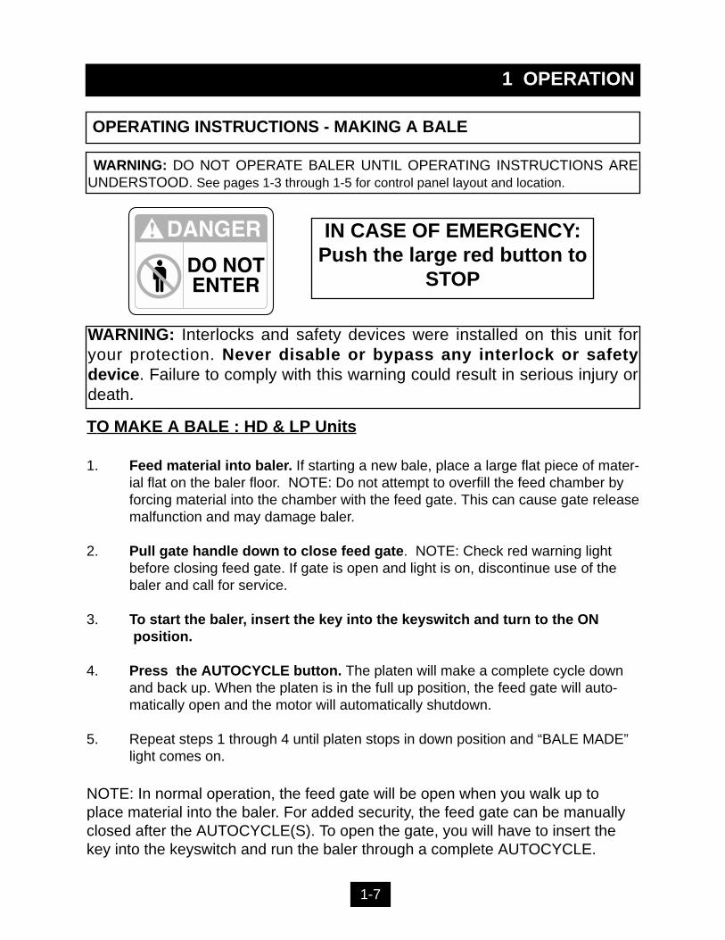
TO MAKE A BALE : HD & LP Units
1. Feed material into baler. If starting a new bale, place a large flat piece of mater-ial flat on the baler floor. NOTE: Do not attempt to overfill the feed chamber by forcing material into the chamber with the feed gate. This can cause gate releasemalfunction and may damage baler.
2. Pull gate handle down to close feed gate. NOTE: Check red warning light before closing feed gate. If gate is open and light is on, discontinue use of the baler and call for service.
3. To start the baler, insert the key into the keyswitch and turn to the ONposition.
4. Press the AUTOCYCLE button. The platen will make a complete cycle down and back up. When the platen is in the full up position, the feed gate will auto-matically open and the motor will automatically shutdown.
5. Repeat steps 1 through 4 until platen stops in down position and “BALE MADE” light comes on.
NOTE: In normal operation, the feed gate will be open when you walk up toplace material into the baler. For added security, the feed gate can be manuallyclosed after the AUTOCYCLE(S). To open the gate, you will have to insert thekey into the keyswitch and run the baler through a complete AUTOCYCLE.
IN CASE OF EMERGENCY:Push the large red button to
STOP
OPERATING INSTRUCTIONS - MAKING A BALE
WARNING: DO NOT OPERATE BALER UNTIL OPERATING INSTRUCTIONS AREUNDERSTOOD. See pages 1-3 through 1-5 for control panel layout and location.
1-7
WARNING: Interlocks and safety devices were installed on this unit foryour protection. Never disable or bypass any interlock or safetydevice. Failure to comply with this warning could result in serious injury ordeath.
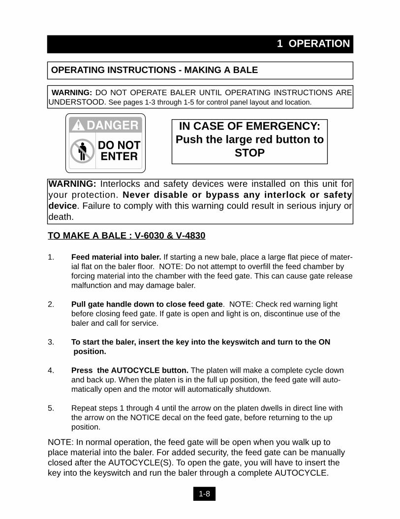
TO MAKE A BALE : V-6030 & V-4830
1. Feed material into baler. If starting a new bale, place a large flat piece of mater-ial flat on the baler floor. NOTE: Do not attempt to overfill the feed chamber by forcing material into the chamber with the feed gate. This can cause gate releasemalfunction and may damage baler.
2. Pull gate handle down to close feed gate. NOTE: Check red warning light before closing feed gate. If gate is open and light is on, discontinue use of the baler and call for service.
3. To start the baler, insert the key into the keyswitch and turn to the ONposition.
4. Press the AUTOCYCLE button. The platen will make a complete cycle down and back up. When the platen is in the full up position, the feed gate will auto-matically open and the motor will automatically shutdown.
5. Repeat steps 1 through 4 until the arrow on the platen dwells in direct line with the arrow on the NOTICE decal on the feed gate, before returning to the up position.
NOTE: In normal operation, the feed gate will be open when you walk up toplace material into the baler. For added security, the feed gate can be manuallyclosed after the AUTOCYCLE(S). To open the gate, you will have to insert thekey into the keyswitch and run the baler through a complete AUTOCYCLE.
WARNING: Interlocks and safety devices were installed on this unit foryour protection. Never disable or bypass any interlock or safetydevice. Failure to comply with this warning could result in serious injury ordeath.
IN CASE OF EMERGENCY:Push the large red button to
STOP
OPERATING INSTRUCTIONS - MAKING A BALE
1 OPERATION
1-8
WARNING: DO NOT OPERATE BALER UNTIL OPERATING INSTRUCTIONS AREUNDERSTOOD. See pages 1-3 through 1-5 for control panel layout and location.
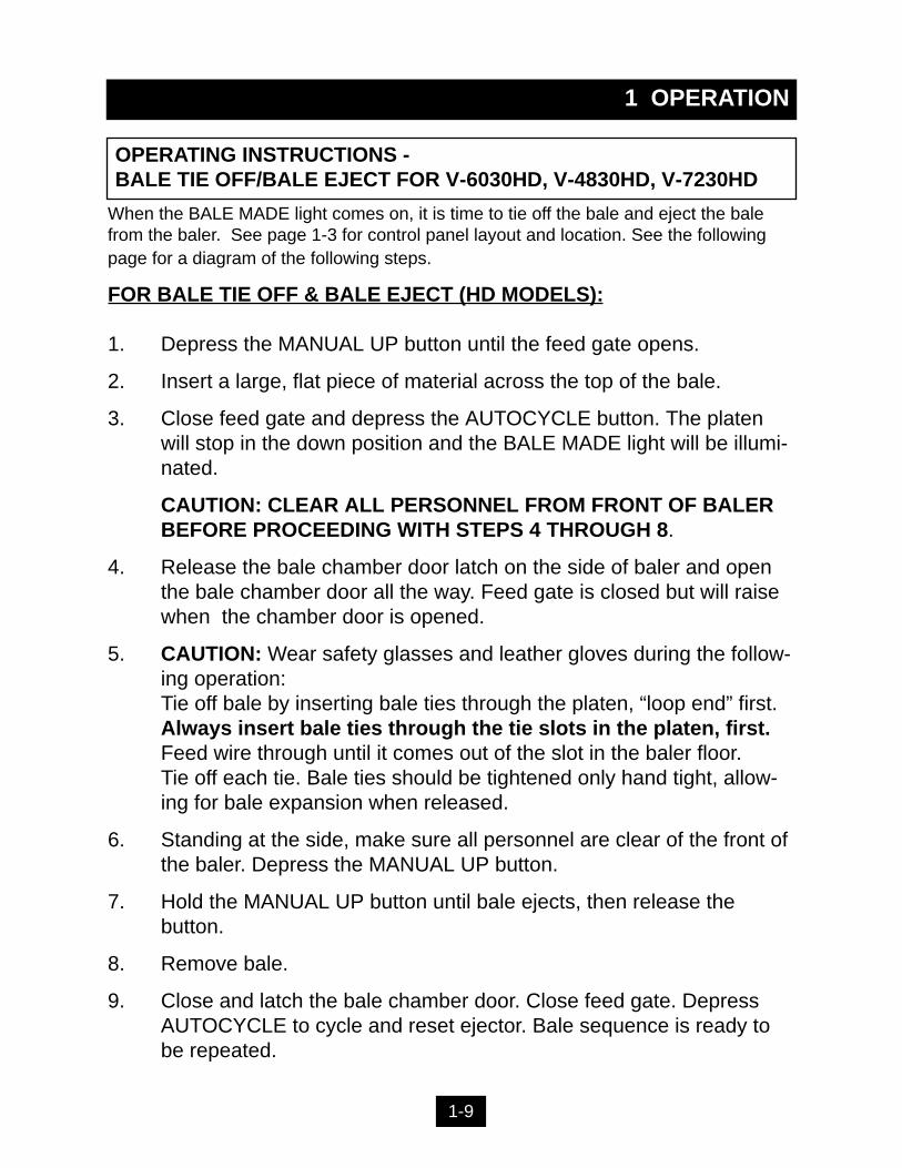
When the BALE MADE light comes on, it is time to tie off the bale and eject the balefrom the baler. See page 1-3 for control panel layout and location. See the followingpage for a diagram of the following steps.
FOR BALE TIE OFF & BALE EJECT (HD MODELS):
1. Depress the MANUAL UP button until the feed gate opens.
2. Insert a large, flat piece of material across the top of the bale.
3. Close feed gate and depress the AUTOCYCLE button. The platen will stop in the down position and the BALE MADE light will be illumi-nated.
CAUTION: CLEAR ALL PERSONNEL FROM FRONT OF BALER BEFORE PROCEEDING WITH STEPS 4 THROUGH 8.
4. Release the bale chamber door latch on the side of baler and open the bale chamber door all the way. Feed gate is closed but will raise when the chamber door is opened.
5. CAUTION: Wear safety glasses and leather gloves during the follow-ing operation:Tie off bale by inserting bale ties through the platen, “loop end” first. Always insert bale ties through the tie slots in the platen, first. Feed wire through until it comes out of the slot in the baler floor. Tie off each tie. Bale ties should be tightened only hand tight, allow-ing for bale expansion when released.
6. Standing at the side, make sure all personnel are clear of the front of the baler. Depress the MANUAL UP button.
7. Hold the MANUAL UP button until bale ejects, then release the button.
8. Remove bale.
9. Close and latch the bale chamber door. Close feed gate. Depress AUTOCYCLE to cycle and reset ejector. Bale sequence is ready to be repeated.
1 OPERATION
OPERATING INSTRUCTIONS -BALE TIE OFF/BALE EJECT FOR V-6030HD, V-4830HD, V-7230HD
1-9
1 OPERATION
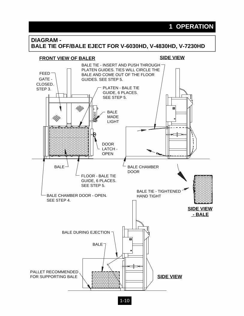
DIAGRAM - BALE TIE OFF/BALE EJECT FOR V-6030HD, V-4830HD, V-7230HD
GATE -CLOSED.STEP 3. PLATEN - BALE TIE
GUIDE, 6 PLACES. SEE STEP 5.
BALEMADELIGHT
DOORLATCH -OPEN
BALE CHAMBER DOOR - OPEN.SEE STEP 4.
FLOOR - BALE TIEGUIDE, 6 PLACES.SEE STEP 5.
FEED
FRONT VIEW OF BALER SIDE VIEW
BALE TIE - TIGHTENEDHAND TIGHT
BALE DURING EJECTION
BALE
PALLET RECOMMENDEDFOR SUPPORTING BALE SIDE VIEW
BALE CHAMBERDOOR
SIDE VIEW - BALE
BALE TIE - INSERT AND PUSH THROUGHPLATEN GUIDES. TIES WILL CIRCLE THEBALE AND COME OUT OF THE FLOORGUIDES. SEE STEP 5.
BALE
1-10
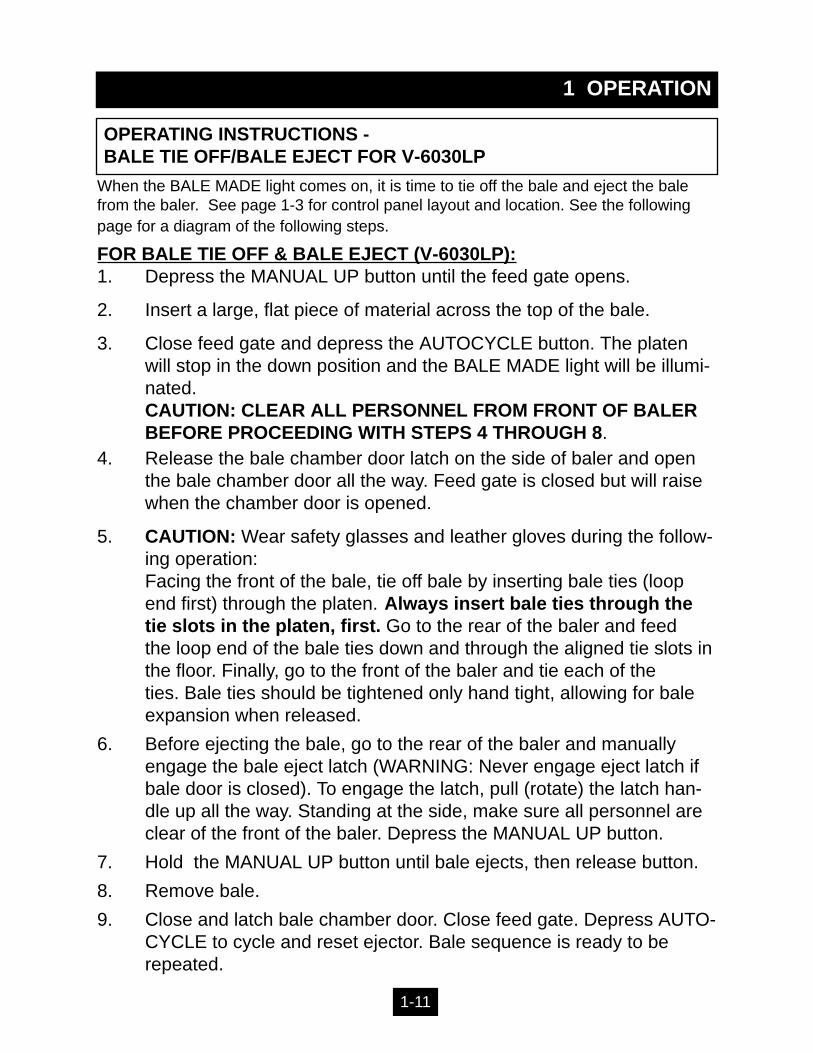
When the BALE MADE light comes on, it is time to tie off the bale and eject the balefrom the baler. See page 1-3 for control panel layout and location. See the followingpage for a diagram of the following steps.
FOR BALE TIE OFF & BALE EJECT (V-6030LP):1. Depress the MANUAL UP button until the feed gate opens.
2. Insert a large, flat piece of material across the top of the bale.
3. Close feed gate and depress the AUTOCYCLE button. The platen will stop in the down position and the BALE MADE light will be illumi-nated.CAUTION: CLEAR ALL PERSONNEL FROM FRONT OF BALER BEFORE PROCEEDING WITH STEPS 4 THROUGH 8.
4. Release the bale chamber door latch on the side of baler and open the bale chamber door all the way. Feed gate is closed but will raise when the chamber door is opened.
5. CAUTION: Wear safety glasses and leather gloves during the follow-ing operation:Facing the front of the bale, tie off bale by inserting bale ties (loop end first) through the platen. Always insert bale ties through the tie slots in the platen, first. Go to the rear of the baler and feed the loop end of the bale ties down and through the aligned tie slots inthe floor. Finally, go to the front of the baler and tie each of the ties. Bale ties should be tightened only hand tight, allowing for bale expansion when released.
6. Before ejecting the bale, go to the rear of the baler and manually engage the bale eject latch (WARNING: Never engage eject latch if bale door is closed). To engage the latch, pull (rotate) the latch han-dle up all the way. Standing at the side, make sure all personnel are clear of the front of the baler. Depress the MANUAL UP button.
7. Hold the MANUAL UP button until bale ejects, then release button.
8. Remove bale.
9. Close and latch bale chamber door. Close feed gate. Depress AUTO-CYCLE to cycle and reset ejector. Bale sequence is ready to be repeated.
1 OPERATION
OPERATING INSTRUCTIONS - BALE TIE OFF/BALE EJECT FOR V-6030LP
1-11

1 OPERATION
DIAGRAM - BALE TIE OFF/BALE EJECT FOR V-6030LP
FEED
GATE
PLATEN - BALE TIEGUIDE, 6 PLACES. SEE STEP 5.
BALEMADELIGHT
DOORLATCH -OPEN
BALE CHAMBER DOOR -OPEN.SEE STEP 4.
FLOOR - BALE TIEGUIDE, 6 PLACES.SEE STEP 5.
FRONT VIEW OF BALER SIDE VIEW
BALE TIE - TIGHTENED
BALE DURING EJECTION- STEP 7.
BALE
PALLET RECOM-MENDED FORSUPPORTINGBALE
SIDE VIEW
BALE CHAMBERDOOR
SIDE VIEW - BALE
BALE TIE - INSERT AND PUSHTHROUGH PLATEN GUIDE.SEE STEP 5.
BALE
- CLOSED.STEP 3.
HAND TIGHT
BALE EJECT LATCH-ENGAGED. STEP 6.
FEED TIESTHROUGHFLOORGUIDES -STEP 5.
1-12
1 OPERATION
OPERATING INSTRUCTIONS - BALE TIE OFF/BALE EJECT FOR V-6042LP
1-13
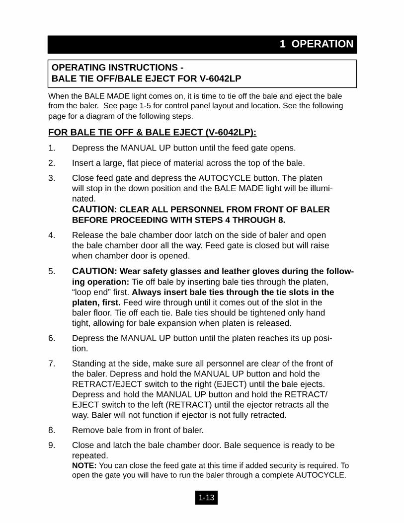
When the BALE MADE light comes on, it is time to tie off the bale and eject the balefrom the baler. See page 1-5 for control panel layout and location. See the followingpage for a diagram of the following steps.
FOR BALE TIE OFF & BALE EJECT (V-6042LP):
1. Depress the MANUAL UP button until the feed gate opens.
2. Insert a large, flat piece of material across the top of the bale.
3. Close feed gate and depress the AUTOCYCLE button. The platen will stop in the down position and the BALE MADE light will be illumi-nated.CAUTION: CLEAR ALL PERSONNEL FROM FRONT OF BALER BEFORE PROCEEDING WITH STEPS 4 THROUGH 8.
4. Release the bale chamber door latch on the side of baler and open the bale chamber door all the way. Feed gate is closed but will raise when chamber door is opened.
5. CAUTION: Wear safety glasses and leather gloves during the follow-ing operation: Tie off bale by inserting bale ties through the platen, “loop end” first. Always insert bale ties through the tie slots in the platen, first. Feed wire through until it comes out of the slot in the baler floor. Tie off each tie. Bale ties should be tightened only hand tight, allowing for bale expansion when platen is released.
6. Depress the MANUAL UP button until the platen reaches its up posi-tion.
7. Standing at the side, make sure all personnel are clear of the front of the baler. Depress and hold the MANUAL UP button and hold the RETRACT/EJECT switch to the right (EJECT) until the bale ejects. Depress and hold the MANUAL UP button and hold the RETRACT/ EJECT switch to the left (RETRACT) until the ejector retracts all the way. Baler will not function if ejector is not fully retracted.
8. Remove bale from in front of baler.
9. Close and latch the bale chamber door. Bale sequence is ready to be repeated.NOTE: You can close the feed gate at this time if added security is required. To open the gate you will have to run the baler through a complete AUTOCYCLE.
1 OPERATION
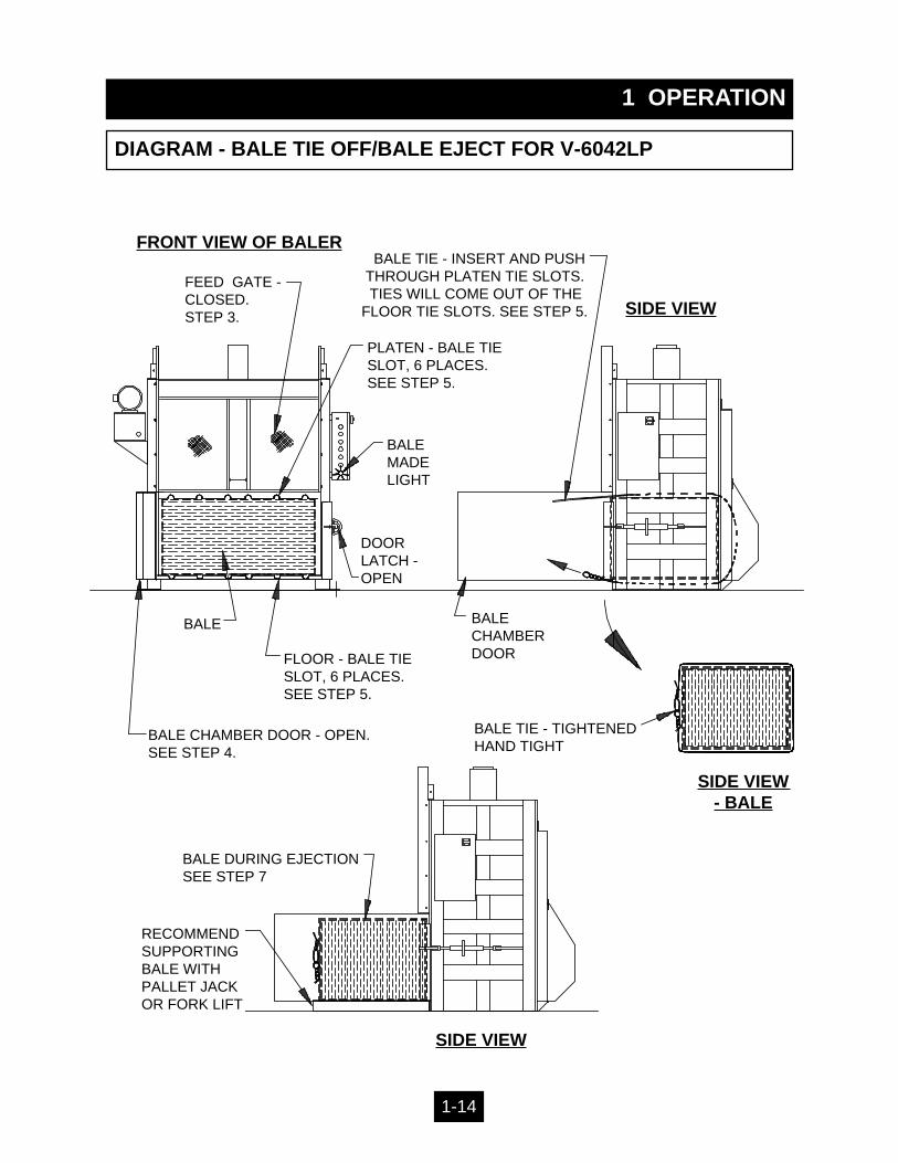
DIAGRAM - BALE TIE OFF/BALE EJECT FOR V-6042LP
1-14
FEED GATE -CLOSED.STEP 3.
PLATEN - BALE TIESLOT, 6 PLACES. SEE STEP 5.
BALEMADELIGHT
DOORLATCH -OPEN
BALE CHAMBER DOOR - OPEN.SEE STEP 4.
FLOOR - BALE TIESLOT, 6 PLACES.SEE STEP 5.
FRONT VIEW OF BALER
SIDE VIEW
BALE TIE - TIGHTENEDHAND TIGHT
BALE DURING EJECTIONSEE STEP 7
RECOMMENDSUPPORTINGBALE WITHPALLET JACKOR FORK LIFT
SIDE VIEW
BALECHAMBERDOOR
SIDE VIEW - BALE
BALE TIE - INSERT AND PUSH THROUGH PLATEN TIE SLOTS. TIES WILL COME OUT OF THE
FLOOR TIE SLOTS. SEE STEP 5.
BALE
1 OPERATION
OPERATING INSTRUCTIONS - BALE TIE OFF/BALE EJECT FOR V-4830 & V-6030
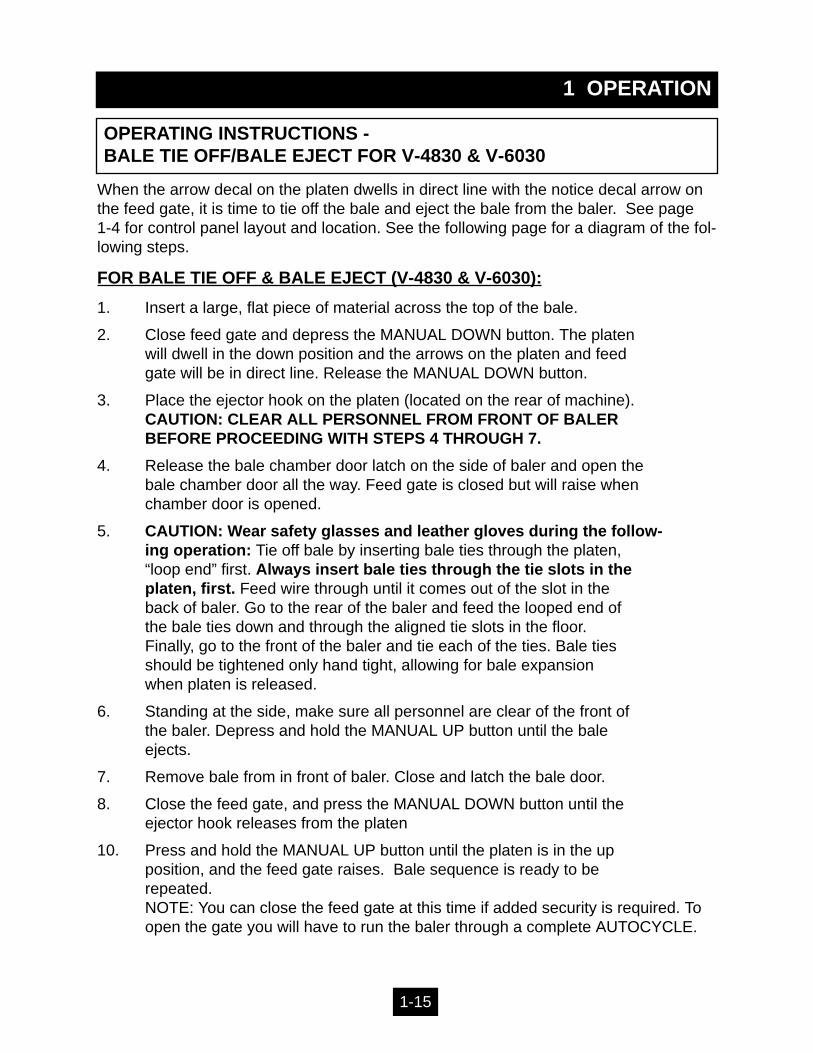
When the arrow decal on the platen dwells in direct line with the notice decal arrow onthe feed gate, it is time to tie off the bale and eject the bale from the baler. See page 1-4 for control panel layout and location. See the following page for a diagram of the fol-lowing steps.
FOR BALE TIE OFF & BALE EJECT (V-4830 & V-6030):
1. Insert a large, flat piece of material across the top of the bale.
2. Close feed gate and depress the MANUAL DOWN button. The platen will dwell in the down position and the arrows on the platen and feed gate will be in direct line. Release the MANUAL DOWN button.
3. Place the ejector hook on the platen (located on the rear of machine).CAUTION: CLEAR ALL PERSONNEL FROM FRONT OF BALER BEFORE PROCEEDING WITH STEPS 4 THROUGH 7.
4. Release the bale chamber door latch on the side of baler and open the bale chamber door all the way. Feed gate is closed but will raise when chamber door is opened.
5. CAUTION: Wear safety glasses and leather gloves during the follow-ing operation: Tie off bale by inserting bale ties through the platen, “loop end” first. Always insert bale ties through the tie slots in the platen, first. Feed wire through until it comes out of the slot in the back of baler. Go to the rear of the baler and feed the looped end of the bale ties down and through the aligned tie slots in the floor. Finally, go to the front of the baler and tie each of the ties. Bale ties should be tightened only hand tight, allowing for bale expansion when platen is released.
6. Standing at the side, make sure all personnel are clear of the front of the baler. Depress and hold the MANUAL UP button until the bale ejects.
7. Remove bale from in front of baler. Close and latch the bale door.
8. Close the feed gate, and press the MANUAL DOWN button until theejector hook releases from the platen
10. Press and hold the MANUAL UP button until the platen is in the upposition, and the feed gate raises. Bale sequence is ready to berepeated.NOTE: You can close the feed gate at this time if added security is required. To open the gate you will have to run the baler through a complete AUTOCYCLE.
1-15
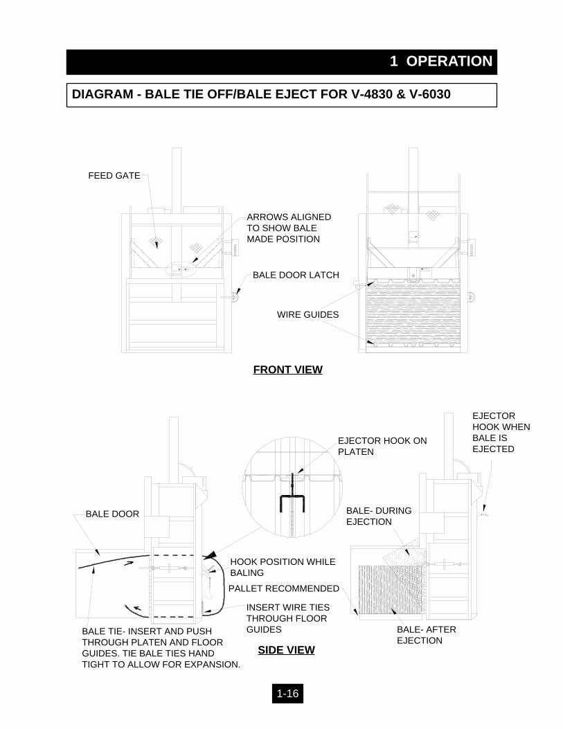
DIAGRAM - BALE TIE OFF/BALE EJECT FOR V-4830 & V-6030
1 OPERATION
FRONT VIEW
SIDE VIEW
WIRE GUIDES
ARROWS ALIGNEDTO SHOW BALEMADE POSITION
EJECTOR HOOK ONPLATEN
INSERT WIRE TIESTHROUGH FLOORGUIDES
PALLET RECOMMENDED
HOOK POSITION WHILEBALING
BALE DOOR
BALE DOOR LATCH
FEED GATE
BALE TIE- INSERT AND PUSHTHROUGH PLATEN AND FLOORGUIDES. TIE BALE TIES HANDTIGHT TO ALLOW FOR EXPANSION.
BALE- AFTEREJECTION
BALE- DURINGEJECTION
EJECTORHOOK WHENBALE ISEJECTED
1-16
1 OPERATION
DIAGRAM - TIE SLOT CLEANING
1-17
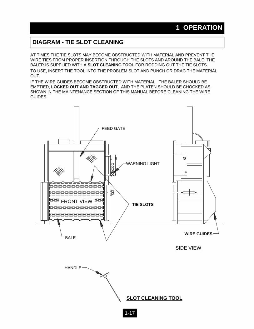
AT TIMES THE TIE SLOTS MAY BECOME OBSTRUCTED WITH MATERIAL AND PREVENT THEWIRE TIES FROM PROPER INSERTION THROUGH THE SLOTS AND AROUND THE BALE. THEBALER IS SUPPLIED WITH A SLOT CLEANING TOOL FOR RODDING OUT THE TIE SLOTS.
TO USE, INSERT THE TOOL INTO THE PROBLEM SLOT AND PUNCH OR DRAG THE MATERIALOUT.
IF THE WIRE GUIDES BECOME OBSTRUCTED WITH MATERIAL , THE BALER SHOULD BE EMPTIED, LOCKED OUT AND TAGGED OUT, AND THE PLATEN SHOULD BE CHOCKED ASSHOWN IN THE MAINTENANCE SECTION OF THIS MANUAL BEFORE CLEANING THE WIREGUIDES.
FRONT VIEW
SIDE VIEW
BALE
WARNING LIGHT
FEED GATE
WIRE GUIDES
TIE SLOTS
SLOT CLEANING TOOL
HANDLE

WARNING DECAL REQUIREMENTS
When your baler leaves the factory, several WARNING DECALS are installed for pro-tection. These labels are subject to wear and abuse due to the nature of the operation.THESE DECALS MUST BE MAINTAINED. Additional decals may be purchasedthrough your distributor.
1 OPERATION
DECALS
DANGER: DO NOT ENTER.
DANGER: 208 VOLTS. or
DANGER: 230 VOLTS. or
DANGER: 460 VOLTS.
DANGER: 208 VOLTS. or
DANGER: 230 VOLTS. or
DANGER: 460 VOLTS.
CAUTION: GATE MUST BE CLOSED BEFORE OPERATINGBALER.
DANGER: KEEP HANDS OUT.
CAUTION: STAND CLEAR WHEN BALE IS EJECTED.
CAUTION: STAND CLEAR WHILE OPERATING DOORLOCK.
NOTICE: PERIODIC MAINTENANCE IS REQUIRED AND ISYOUR RESPONSIBILITY.
DANGER. DISCONNECT AND LOCK OUT POWERBEFORE OPENING THIS PANEL.
WARNING: FEDERAL REGULATION PROHIBITS OPERA-TION OF THIS EQUIPMENT BY PERSONS UNDER 18YEARS OF AGE.
MARATHON EQUIPMENT COMPANY.
Decal Number 06-0039 -
Decal Number 06-0043 -
Decal Number 06-0044 -
Decal Number 06-0045 -
Decal Number 06-0101 -
Decal Number 06-0102 -
Decal Number 06-0103 -
Decal Number 06-0115 -
Decal Number 06-0116 -
Decal Number 06-0117 -
Decal Number 06-0118 -
Decal Number 06-0119 -
Decal Number 06-0120 -
Decal Number 06-0121 -
Decal Number 06-0126 -
1-18
WARNING DECAL REQUIREMENTS
When your baler leaves the factory, several WARNING DECALS are installed for pro-tection. These labels are subject to wear and abuse due to the nature of the operation.THESE DECALS MUST BE MAINTAINED. Additional decals may be purchasedthrough your distributor.
1 OPERATION
DECALS
CAUTION: DO NOT OPERATE BALER UNTIL OPERATINGINSTRUCTIONS ARE UNDERSTOOD. NEVER PLACE ANYPART OF BODY INSIDE BALE CHAMBER. STAND CLEARWHILE BALER IS IN OPERATION. FEDERAL LAW PRO-HIBITS OPERATION OF THIS EQUIPMENT BY PERSONSUNDER 18 YEARS OF AGE. TURN OFF AND REMOVE KEYAFTER USE. STAND CLEAR WHILE EJECTING BALE.(Also, includes Operating Instructions).
WARNING: STAY CLEAR OF BALE CHAMBER WHENLIGHT IS ILLUMINATED. IF LIGHT IS ILLUMINATED WHENBALE DOOR OR FEED GATE IS OPEN, DISCONTINUEUSE OF THIS EQUIPMENT AND CALL QUALIFIED SER-VICE PERSONNEL.
DANGER: STAY OFF TOP BALER. DO NOT CLIMB ONSIDES. USE WORK PLATFORM FOR SERVICING.
NOTICE BALE MADE IF ARROW DOES NOT PASS.(V-4830 & V-6030 ONLY)
ORANGE ARROW.(V-4830 & V-6030 ONLY)
Decal Number 06-0130 -
Decal Number 06-0132 -
Decal Number 06-0133 -
Decal Number 06-0651-
Decal Number 06-0652 -
1-19
1 OPERATION
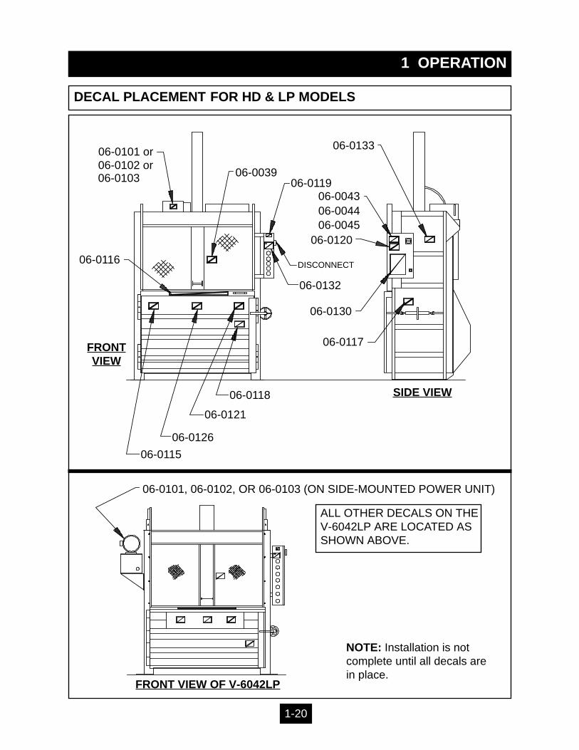
DECAL PLACEMENT FOR HD & LP MODELS
06-0116
06-0103 06-0039
DISCONNECT
06-0132
06-0117
06-0130
06-0119
06-0120
06-0043
06-0133
06-0118
06-0121
06-0126
06-0115
06-0102 or06-0101 or
06-004406-0045
FRONTVIEW
SIDE VIEW
1-20
FRONT VIEW OF V-6042LP
06-0101, 06-0102, OR 06-0103 (ON SIDE-MOUNTED POWER UNIT)
ALL OTHER DECALS ON THE V-6042LP ARE LOCATED AS SHOWN ABOVE.
NOTE: Installation is notcomplete until all decals arein place.
1 OPERATION
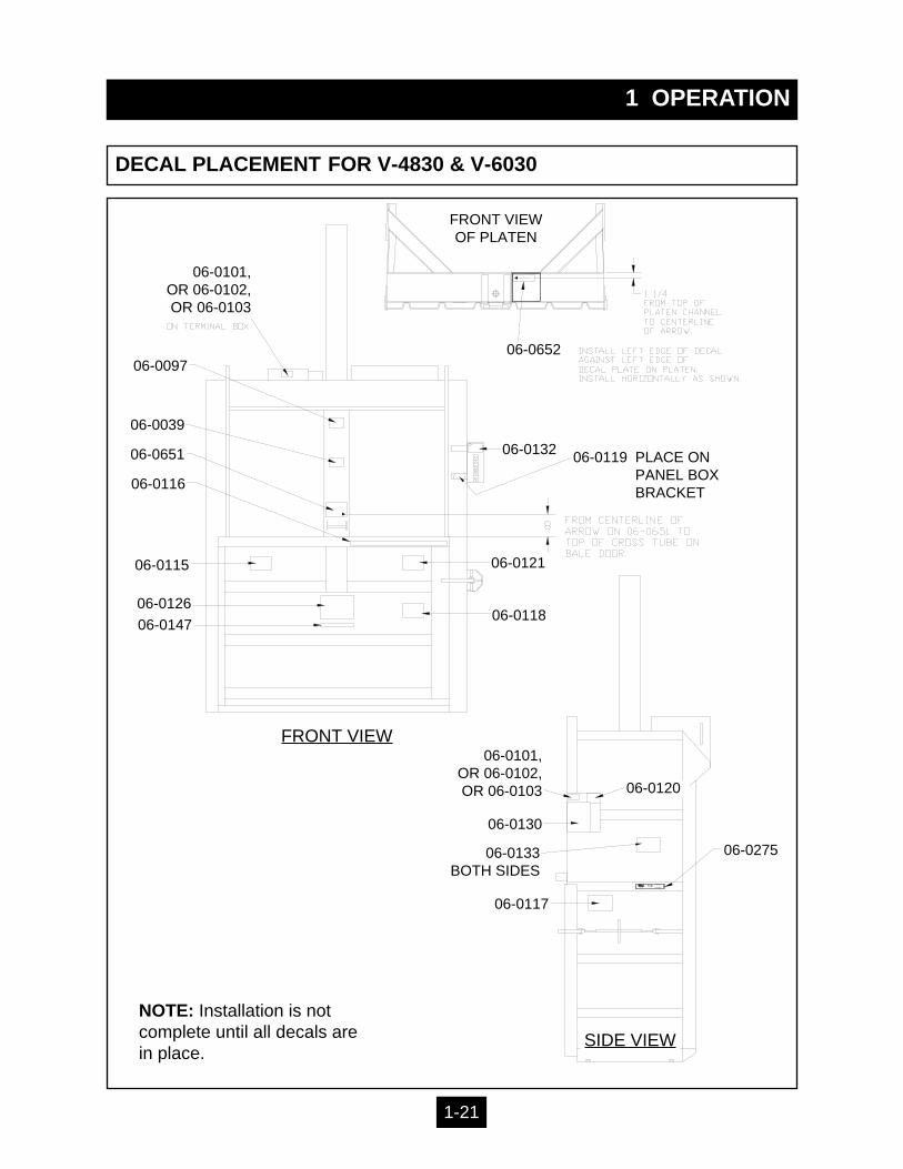
DECAL PLACEMENT FOR V-4830 & V-6030
ULR ULL IS T ED
1 6 B F
CD OV ER
V E R N O N , A L − Y E R IN G T O N , N V − C LEA R FIELD, PA1−8 00 −6 33 −89 74
VERTICAL BALERPATENT # 5,044,271
MODEL
SERIAL #T H IS PR O D U C T COM PLIES W ITH
A NS I Z245 .5 −199 0.
RR
FRONT VIEWOF PLATEN
06-0101,OR 06-0102,OR 06-0103
06-0652
06-0132 06-0119 PLACE ONPANEL BOXBRACKET
06-0121
06-0118
06-0275
FRONT VIEW
SIDE VIEW
06-0120
06-0101,OR 06-0102,OR 06-0103
06-0130
06-0133BOTH SIDES
06-0117
06-0097
06-0039
06-0651
06-0116
06-0115
06-0126
06-0147
NOTE: Installation is notcomplete until all decals arein place.
1-21

2 MAINTENANCE
LOCK-OUT & TAG-OUT INSTRUCTIONS
ELECTRICAL: The panel box contains high voltagecomponents. Only authorized service personnelshould be allowed inside the box. Authorized servicepersonnel should be allowed inside the box onlyafter the baler has been locked-out and tagged-out.
FOREWORD: Before entering any part of the baler, besure that all sources of energy have been shut off, allpotential hazards have been eliminated, and the baleris locked-out and tagged-out in accordance withOSHA and ANSI requirements. Before servicing thehydraulic system or the inside of the bale chamber,THE PLATEN MUST BE PROPERLY SUPPORTED ASSHOWN ON THE NEXT PAGE. The specific lock-out andtag-out instructions may vary from company to company (i.e.multiple locks may be required, or other machinery may need tobe locked-out and tagged-out). The following instructions areprovided as minimum guidelines.
INSTRUCTIONS
1. Move the main disconnect lever to the OFF position. The disconnect switch onmodels V-4830 & V-6030 is located in the disconnect panel on the wall. The disconnectswitch on all other models is located in the panel box of the machine.
2. Padlock the disconnect lever with a keyed padlock and take the key withyou. (To insert the lock through the lock tab on the disconnect handle, pull the lock tab out ofthe disconnect handle when the handle is in the OFF position.)
3. Along with the padlock, place an appropriate, highly visible, warning tag onthe disconnect lever. The tag should provide a warning such as: “ Danger: Do not oper-ate equipment. Person working on equipment.” or “ Warning: Do not energize without the per-mission of ________________________.”
4. After locking and tagging the baler, try to start and operate the baler (as out-lined in the Operating Instructions) to make sure the lock-out and tag-out iseffective. If the lock-out and tag-out is effective, remove the key from thekeyswitch and take it with you.
HYDRAULIC: Stored hydraulic energy must be removed from the baler hydraulic cir-cuit for complete lock-out and tag-out. Make sure that this energy has been relievedby manually depressing the solenoid valve pin located in the center of the coil end ofeach valve.
2-1
(Typical disconnect shown, other types may lock-out differently.)
2 MAINTENANCE
SUPPORTING OF PLATEN
BALE CHAM-BER DOOR,OPEN
FEED GATE OPEN -PLATEN IN UPPOSITION
DISCONNECTIN OFF POSI-TION ANDLOCKED-OUT
4” X 4” WOODBEAM IN EACH REAR CORNER
FRONT VIEW OF BALER
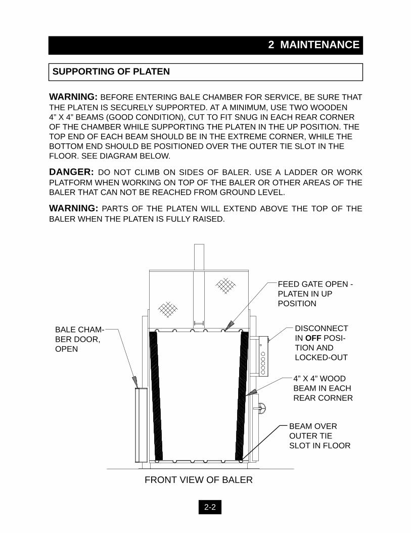
WARNING: BEFORE ENTERING BALE CHAMBER FOR SERVICE, BE SURE THATTHE PLATEN IS SECURELY SUPPORTED. AT A MINIMUM, USE TWO WOODEN 4” X 4” BEAMS (GOOD CONDITION), CUT TO FIT SNUG IN EACH REAR CORNEROF THE CHAMBER WHILE SUPPORTING THE PLATEN IN THE UP POSITION. THETOP END OF EACH BEAM SHOULD BE IN THE EXTREME CORNER, WHILE THEBOTTOM END SHOULD BE POSITIONED OVER THE OUTER TIE SLOT IN THEFLOOR. SEE DIAGRAM BELOW.
DANGER: DO NOT CLIMB ON SIDES OF BALER. USE A LADDER OR WORKPLATFORM WHEN WORKING ON TOP OF THE BALER OR OTHER AREAS OF THEBALER THAT CAN NOT BE REACHED FROM GROUND LEVEL.
WARNING: PARTS OF THE PLATEN WILL EXTEND ABOVE THE TOP OF THEBALER WHEN THE PLATEN IS FULLY RAISED.
BEAM OVEROUTER TIESLOT IN FLOOR
2-2

Check external hoses for chafing, rubbing, leakage, or other deterioration and dam-age. Tighten all fittings as necessary. Check hydraulic cylinder, cylinder pin andbolts for signs of wear and fatigue.Check for any obvious unsafe conditions, such as operator obstructions, in balerarea.Check oil level in hydraulic reservoir.Lubricate the door hinge, and mechanical door lock with oil.Check magnetic interlock on feed gate for proper operation.Clean out wire guides on machines equipped with them. Follow platen chockingprocedures and lock out and tag out procedures.Check guide shoes for wear, and lubricate as needed with an all purpose grease.Apply a light coating of all purpose grease in the feed gate tracks.Apply a light application of all purpose oil to the feed gate latch moving parts.
Check functional operation of controls and options (stop button, timers, lights, etc.).Check hydraulic cylinder, and hoses, for leakage, chafing and wear.
The hydraulic filter should be cleaned at regular annual intervals.
The filter may be removed from the power unit through the cleanout cover in the topof the reservoir.
Care should be exercised in cleaning the fiIter to insure that the element is not torn.Clean the element with a soft brush and standard industrial solvent.
Replace the filter after cleaning and check fittings for tightness. Pump noise and a"crackle" sound is most often caused by air entering the pump suction line.Tightening the suction fittings will usually eliminate the problem.
2 MAINTENANCE
PERIODIC MAINTENANCE
1.
2.
3.4.5.6.
7.8.9.
1.2.
1.
2.
3.
4.
MONTHLY
THREE MONTHS
ANNUAL FILTER MAINTENANCE
ANNUALLY
1.2.3.
Replace the hydraulic fluid. See Recommended Oil.Electric motor bearings should be lubricated once a year.Clean the top of the power unit to remove the dirt build up.
2-3
WARNING: BEFORE PERFORMING ANY MAINTENANCE OR SERVICE PROCEDURES ON THE BALER, MAKE SURE THE BALER IS LOCKED-OUT AND TAGGED OUT PER THE INSTRUCTIONS ON PAGE 2-1. FOR MAINTENANCE INSIDE THE BALE CHAMBER, SEE THE PLATEN CHOCKING PROCEDURE ON PAGE 2-2.
With the key switch in the ON position, use the MANUAL DOWN button to move theplaten to the full down position.Turn off the power and perform the LOCK-OUT and TAG-OUT proceduresdescribed on page 2-1.Manually shift the solenoid valve in each direction to relieve pressure. Remove the 1/4” plug from the 3/4” 90 degree elbow in the valve subplate. Install a pressure gauge in the 1/4” hole.Remove the Lock-out and Tag-out provisions and turn on power to the baler.Have an operator hold the MANUAL DOWN button. This will start the baler and thehydraulic system will build relief pressure. Turn the adjustment screw on the reliefvalve clockwise to increase the pressure, or counter clockwise to decrease thepressure. See CHARTS for proper setting for your model.Tighten locknut on adjustment screw.Have the operator release the MANUAL DOWN button and press the STOP button.Turn off the power and perform the LOCK-OUT and TAG-OUT proceduresdescribed on page 2-1.Remove the pressure gauge and reinstall the 1/4” plug. This procedure is complete.
1.
2.
3.4.5.6.7.
8.9.
10.
11.12.
2 MAINTENANCE
PROCEDURES - PRESSURE SETTING, INTERLOCK TESTING
HYDRAULIC SYSTEM PRESSURE SETTING
MAGNETIC INTERLOCK TESTING
1.
2.
3.
4.
This baler is equipped with a solid state output magnetic interlock switch. Becauseit is a semiconductor device, it can not be checked with a continuity light or OHMtester. The switch must be checked with the power ON. The RED WARNINGLIGHT on the control panel has been provided to indicate if the switch is workingproperly. To check the switch, turn the keyswitch to the ON position. When the feed gate orbale door is open, the light should be off. When the bale door and feed gate areclosed, the light should be on.If further verification is required, a volt meter (120V) may be connected to terminal#2A and terminal #7 in the panel box. The meter should read “0” volts with the gateopen and 120 volts with the gate closed.In no instance should the baler operate in either MANUAL DOWN or AUTOCYCLEwith the feed gate up or bale door open.WARNING: IF THE INTERLOCK IS NOT WORKING PROPERLY, DISCONNECTTHE POWER AND LOCK-OUT AND TAG-OUT THE BALER UNTIL REPAIRS CANBE MADE.
DANGER: DO NOT CLIMB ON SIDES OF BALER. USE A LADDER OR WORK PLATFORMWHEN WORKING ON TOP OF THE BALER OR OTHER AREAS OF THE BALER THAT CANNOT BE REACHED FROM GROUND LEVEL.
WARNING: PARTS OF THE PLATEN WILL EXTEND ABOVE THE TOP OF THE BALERWHEN THE PLATEN IS FULLY RAISED.
2-4
2 MAINTENANCE
PROCEDURES - CYLINDER REMOVAL
CYLINDER REMOVAL (ALL UNITS EXCEPT LOW PROFILE, LP)Raise platen up to the top position with the MANUAL UP button.Disconnect and Lock-out and Tag-out power per instructions on page 2-1.Remove guide shoes.Turn on power and lower platen using the MANUAL DOWN button. Turn off power.Support platen with fork lift to take pressure off of cylinder pin and to prevent platen from fallingwhen pin is removed.Remove bolts and cotter pins in cylinder pin.Remove platen from front of baler.Turn on power and retract cylinder rod.Disconnect and Lock-out and Tag-out power.Relieve hydraulic pressure by manually depressing solenoid valve (both sides).Disconnect one hydraulic hose at a time. Plug the hose port before disconnecting the other hose.NOTE: Remove hose fittings slowly.WARNING: BE SURE HYDRAULIC CYLINDER IS SECURELY SUPPORTED BEFORE PRO-CEEDING.With the hydraulic cylinder supported, loosen the 3/4” grade 5 cylinder bolts and grade 5 locknuts.Remove cylinder.Before reinstalling cylinder, check cylinder pin, bolts, and cylinder rod for signs of fatigue. Do notreuse parts if wear or cracks are present.To reinstall the cylinder, reverse the above steps.Be sure to use new bolts, nuts, and cotter pins in the cylinder pin.
1.2.3.4.5.
6.7.8.9.
10.11.
12.
13.14.15.
16.
DANGER: DO NOT CLIMB ON SIDES OF BALER. USE A LADDER OR WORK PLATFORM WHENWORKING ON TOP OF THE BALER OR OTHER AREAS OF THE BALER THAT CAN NOT BEREACHED FROM GROUND LEVEL.
WARNING: PARTS OF THE PLATEN WILL EXTEND ABOVE THE TOP OF THE BALER WHEN THEPLATEN IS FULLY RAISED.
2-5
MAIN CYLINDER REMOVAL - LOW PROFILERaise platen up to the top position with MANUAL UP button. Lock-out and Tag-out power perinstructions on page 2-1. Remove guide shoes.Turn on power and lower platen using MANUAL DOWN button. Turn off power.Support platen with fork lift to take pressure off of cylinder pin and to prevent platen from fallingwhen pin is removed. NOTE: Because of the long pin length, make sure the fork lift is no closerthan 24” to the platen.Remove the two bolts attaching the cylinder pin assembly to the front of the platen. The cylinder pinassembly consists of a 21 3/4” long pin (1 1/2” dia) with a ”U” bracket welded to the end. This brack-et fastens to the front of the platen with the two bolts. Slide the pin assembly out of the cylinder andplaten.Remove platen from front of baler. Turn on power and retract cylinder rod.Disconnect and Lock-out and Tag-out power. Relieve hydraulic pressure per Lock-out and Tag-out.Disconnect one hydraulic hose at a time. Plug the hose port before disconnecting the other hose.NOTE: Remove hose fittings slowly.WARNING: SUPPORT HYDRAULIC CYLINDER BEFORE PROCEEDING.With the hydraulic cylinder supported, remove the 1” grade 5 cylinder bolts and grade 5 locknuts.Remove cylinder.Before reinstalling cylinder, check cylinder pin, bolts, and cylinder rod for signs of fatigue. Do notreuse parts if wear or cracks are present.To reinstall the cylinder, reverse the above steps. Be sure to use new bolts, and cotter pins in thecylinder pin.
1.
2.3.
4.
5.6.7.
8.9.
10.11.
12.
2 MAINTENANCE
PROCEDURES - CYLINDER REBUILDING, LIMIT SWITCH ADJUSTMENT
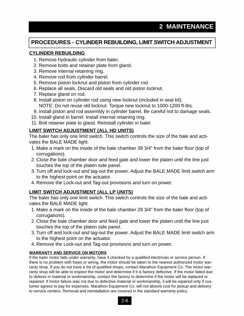
CYLINDER REBUILDINGRemove hydraulic cylinder from baler.Remove bolts and retainer plate from gland.Remove internal retaining ring.Remove rod from cylinder barrel.Remove piston locknut and piston from cylinder rod.Replace all seals. Discard old seals and old piston locknut.Replace gland on rod.Install piston on cylinder rod using new locknut (included in seal kit).NOTE: Do not reuse old locknut. Torque new locknut to 1000-1200 ft-lbs.Install piston and rod assembly in cylinder barrel. Be careful not to damage seals.Install gland in barrel. Install internal retaining ring.Bolt retainer plate to gland. Reinstall cylinder in baler.
1.2.3.4.5.6.7.8.
9.10.11.
WARRANTY AND SERVICE ON MOTORSIf the baler motor fails under warranty, have it checked by a qualified electrician or service person. Ifthere is no problem with fuses or wiring, the motor should be taken to the nearest authorized motor war-ranty shop. If you do not have a list of qualified shops, contact Marathon Equipment Co. The motor war-ranty shop will be able to inspect the motor and determine if it is factory defective. If the motor failed dueto defects in material or workmanship, contact the factory to determine if the motor will be replaced orrepaired. If motor failure was not due to defective material or workmanship, it will be repaired only if cus-tomer agrees to pay for expenses. Marathon Equipment Co. will not absorb cost for pickup and deliveryto service centers. Removal and reinstallation are covered in the standard warranty policy.
2-6
LIMIT SWITCH ADJUSTMENT (ALL HD UNITS)The baler has only one limit switch. This switch controls the size of the bale and acti-vates the BALE MADE light.
Make a mark on the inside of the bale chamber 39 3/4” from the baler floor (top ofcorrugations).Close the bale chamber door and feed gate and lower the platen until the line justtouches the top of the platen side panel.Turn off and lock-out and tag-out the power. Adjust the BALE MADE limit switch armto the highest point on the actuator.Remove the Lock-out and Tag-out provisions and turn on power.
1.
2.
3.
4.
LIMIT SWITCH ADJUSTMENT (ALL LP UNITS)The baler has only one limit switch. This switch controls the size of the bale and acti-vates the BALE MADE light.
Make a mark on the inside of the bale chamber 29 3/4” from the baler floor (top ofcorrugations).Close the bale chamber door and feed gate and lower the platen until the line justtouches the top of the platen side panel.Turn off and lock-out and tag-out the power. Adjust the BALE MADE limit switch armto the highest point on the actuator.Remove the Lock-out and Tag-out provisions and turn on power.
1.
2.
3.
4.
2 MAINTENANCE
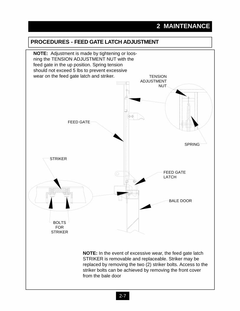
PROCEDURES - FEED GATE LATCH ADJUSTMENT
BALE DOOR
FEED GATELATCH
SPRING
FEED GATE
STRIKER
TENSIONADJUSTMENT
NUT
BOLTSFOR
STRIKER
NOTE: Adjustment is made by tightening or loos-ning the TENSION ADJUSTMENT NUT with thefeed gate in the up position. Spring tensionshould not exceed 5 lbs to prevent excessivewear on the feed gate latch and striker.
NOTE: In the event of excessive wear, the feed gate latchSTRIKER is removable and replaceable. Striker may bereplaced by removing the two (2) striker bolts. Access to thestriker bolts can be achieved by removing the front coverfrom the bale door
2-7
2 MAINTENANCE
PRINCIPLES OF OPERATION
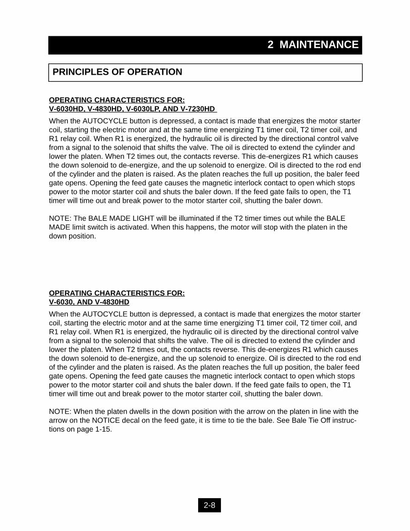
OPERATING CHARACTERISTICS FOR:V-6030HD, V-4830HD, V-6030LP, AND V-7230HD
When the AUTOCYCLE button is depressed, a contact is made that energizes the motor startercoil, starting the electric motor and at the same time energizing T1 timer coil, T2 timer coil, andR1 relay coil. When R1 is energized, the hydraulic oil is directed by the directional control valvefrom a signal to the solenoid that shifts the valve. The oil is directed to extend the cylinder andlower the platen. When T2 times out, the contacts reverse. This de-energizes R1 which causesthe down solenoid to de-energize, and the up solenoid to energize. Oil is directed to the rod endof the cylinder and the platen is raised. As the platen reaches the full up position, the baler feedgate opens. Opening the feed gate causes the magnetic interlock contact to open which stopspower to the motor starter coil and shuts the baler down. If the feed gate fails to open, the T1timer will time out and break power to the motor starter coil, shutting the baler down.
NOTE: The BALE MADE LIGHT will be illuminated if the T2 timer times out while the BALEMADE limit switch is activated. When this happens, the motor will stop with the platen in thedown position.
2-8
OPERATING CHARACTERISTICS FOR:V-6030, AND V-4830HD
When the AUTOCYCLE button is depressed, a contact is made that energizes the motor startercoil, starting the electric motor and at the same time energizing T1 timer coil, T2 timer coil, andR1 relay coil. When R1 is energized, the hydraulic oil is directed by the directional control valvefrom a signal to the solenoid that shifts the valve. The oil is directed to extend the cylinder andlower the platen. When T2 times out, the contacts reverse. This de-energizes R1 which causesthe down solenoid to de-energize, and the up solenoid to energize. Oil is directed to the rod endof the cylinder and the platen is raised. As the platen reaches the full up position, the baler feedgate opens. Opening the feed gate causes the magnetic interlock contact to open which stopspower to the motor starter coil and shuts the baler down. If the feed gate fails to open, the T1timer will time out and break power to the motor starter coil, shutting the baler down.
NOTE: When the platen dwells in the down position with the arrow on the platen in line with thearrow on the NOTICE decal on the feed gate, it is time to tie the bale. See Bale Tie Off instruc-tions on page 1-15.

2 MAINTENANCE
PRINCIPLES OF OPERATION
V-6042 XLP OPERATING CHARACTERISTICS
Feed Gate and Platen OperationWhen the AUTOCYCLE button is depressed, a contact is made that energizes the motor startercoil, starting the electric motor and at the same time energizing T1 timer coil, T2 timer coil, andR1 relay coil. When R1 is energized, the hydraulic oil is directed by the directional control valvefrom a signal to the SV1A solenoid that shifts the valve. The oil is directed to the base end ofthe cylinder to extend the cylinder and lower the platen. When T2 times out, the contactsreverse. This de-energizes R1 which causes the down solenoid to de-energize, and the upsolenoid (SV1B) to energize. Oil is directed to the rod end of the cylinder and the platen israised. As the platen reaches the full up position, the baler feed gate opens. Opening the feedgate causes the magnetic interlock contact to open which stops power to the motor starter coiland shuts the baler down. If the feed gate fails to open, the T1 timer will time out and breakpower to the motor starter coil, shutting the baler down. NOTE: The BALE MADE LIGHT will beilluminated if the T2 timer times out while the BALE MADE limit switch is activated. When thishappens, the motor will stop with the platen in the down position.
Ejector OperationWhen the bale is ejected, the MANUAL UP button must be depressed and held which ener-gizes the motor starter coil, starting the electric motor. At the same time, the RETRACT/EJECTswitch must be turned and held to the right (EJECT). This energizes the coil on the SV2A sole-noid valve causing it to shift and direct fluid to the base end of the cylinder which cause theejector to eject the bale.When the ejector is retracted, the MANUAL UP button must be depressed and held which ener-gizes the motor starter coil, starting the electric motor. At the same time, the RETRACT/EJECTswitch must be turned and held to the left (RETRACT). This energizes the coil on the SV2Bsolenoid valve causing it to shift and direct fluid to the rod end of the cylinder which cause theejector to retract.
2-9
2 MA
INT
EN
AN
CE
BA
LE
R S
PE
CIF
ICA
TIO
NS
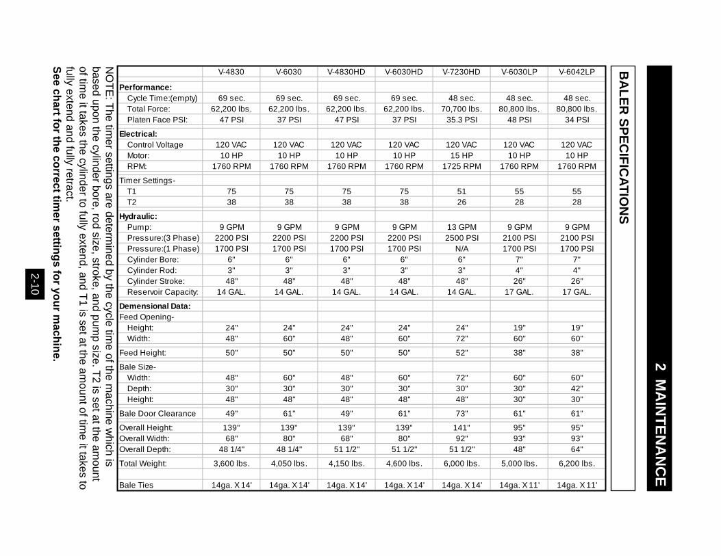
V-4830 V-6030 V-4830HD V-6030HD V-7230HD V-6030LP V-6042LP
Performance: Cycle Time:(empty) 69 sec. 69 sec. 69 sec. 69 sec. 48 sec. 48 sec. 48 sec. Total Force: 62,200 lbs. 62,200 lbs. 62,200 lbs. 62,200 lbs. 70,700 lbs. 80,800 lbs. 80,800 lbs. Platen Face PSI: 47 PSI 37 PSI 47 PSI 37 PSI 35.3 PSI 48 PSI 34 PSI
Electrical: Control Voltage 120 VAC 120 VAC 120 VAC 120 VAC 120 VAC 120 VAC 120 VAC Motor: 10 HP 10 HP 10 HP 10 HP 15 HP 10 HP 10 HP RPM: 1760 RPM 1760 RPM 1760 RPM 1760 RPM 1725 RPM 1760 RPM 1760 RPM
Timer Settings- T1 75 75 75 75 51 55 55 T2 38 38 38 38 26 28 28
Hydraulic: Pump: 9 GPM 9 GPM 9 GPM 9 GPM 13 GPM 9 GPM 9 GPM Pressure:(3 Phase) 2200 PSI 2200 PSI 2200 PSI 2200 PSI 2500 PSI 2100 PSI 2100 PSI Pressure:(1 Phase) 1700 PSI 1700 PSI 1700 PSI 1700 PSI N/A 1700 PSI 1700 PSI Cylinder Bore: 6" 6" 6" 6" 6" 7" 7" Cylinder Rod: 3" 3" 3" 3" 3" 4" 4" Cylinder Stroke: 48" 48" 48" 48" 48" 26" 26" Reservoir Capacity: 14 GAL. 14 GAL. 14 GAL. 14 GAL. 14 GAL. 17 GAL. 17 GAL.
Demensional Data:Feed Opening- Height: 24" 24" 24" 24" 24" 19" 19" Width: 48" 60" 48" 60" 72" 60" 60"
Feed Height: 50" 50" 50" 50" 52" 38" 38"
Bale Size- Width: 48" 60" 48" 60" 72" 60" 60" Depth: 30" 30" 30" 30" 30" 30" 42" Height: 48" 48" 48" 48" 48" 30" 30"
Bale Door Clearance 49" 61" 49" 61" 73" 61" 61"
Overall Height: 139" 139" 139" 139" 141" 95" 95"Overall Width: 68" 80" 68" 80" 92" 93" 93"Overall Depth: 48 1/4" 48 1/4" 51 1/2" 51 1/2" 51 1/2" 48" 64"
Total Weight: 3,600 lbs. 4,050 lbs. 4,150 lbs. 4,600 lbs. 6,000 lbs. 5,000 lbs. 6,200 lbs.
Bale Ties 14ga. X 14' 14ga. X 14' 14ga. X 14' 14ga. X 14' 14ga. X 14' 14ga. X 11' 14ga. X 11'
2-1
0
NO
TE
: The tim
er se
ttings a
re d
ete
rmin
ed b
y the cycle
time o
f the m
ach
ine w
hich
isbase
d u
pon th
e cylin
der b
ore
, rod size
, stroke
, and p
um
p size
. T2 is se
t at th
e a
mo
unt
of tim
e it ta
kes th
e cylin
der to
fully e
xtend, a
nd T
1 is se
t at th
e a
mount o
f time it ta
kes to
fully e
xtend a
nd fu
lly retra
ct.S
ee chart fo
r the co
rrect timer settin
gs fo
r you
r mach
ine.
2 MAINTENANCE
PROCEDURES - TIMER ADJUSTMENT
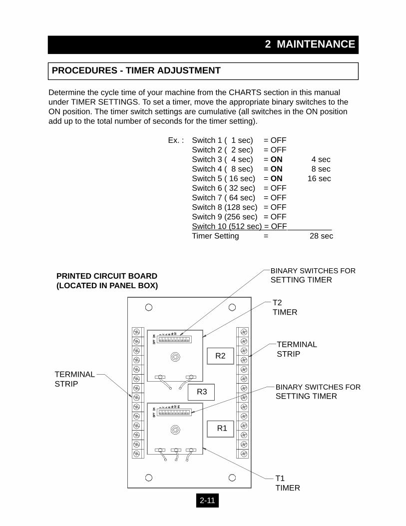
Determine the cycle time of your machine from the CHARTS section in this manualunder TIMER SETTINGS. To set a timer, move the appropriate binary switches to theON position. The timer switch settings are cumulative (all switches in the ON positionadd up to the total number of seconds for the timer setting).
Ex. : Switch 1 ( 1 sec) = OFFSwitch 2 ( 2 sec) = OFFSwitch 3 ( 4 sec) = ON 4 secSwitch 4 ( 8 sec) = ON 8 secSwitch 5 ( 16 sec) = ON 16 secSwitch 6 ( 32 sec) = OFFSwitch 7 ( 64 sec) = OFFSwitch 8 (128 sec) = OFFSwitch 9 (256 sec) = OFFSwitch 10 (512 sec) = OFFTimer Setting = 28 sec
T1TIMER
T2TIMER
BINARY SWITCHES FORSETTING TIMER
PRINTED CIRCUIT BOARD(LOCATED IN PANEL BOX)
BINARY SWITCHES FORSETTING TIMER
TERMINAL STRIP
TERMINAL STRIP
R2
R3
R1
2-11
2 MAINTENANCE
CHARTS
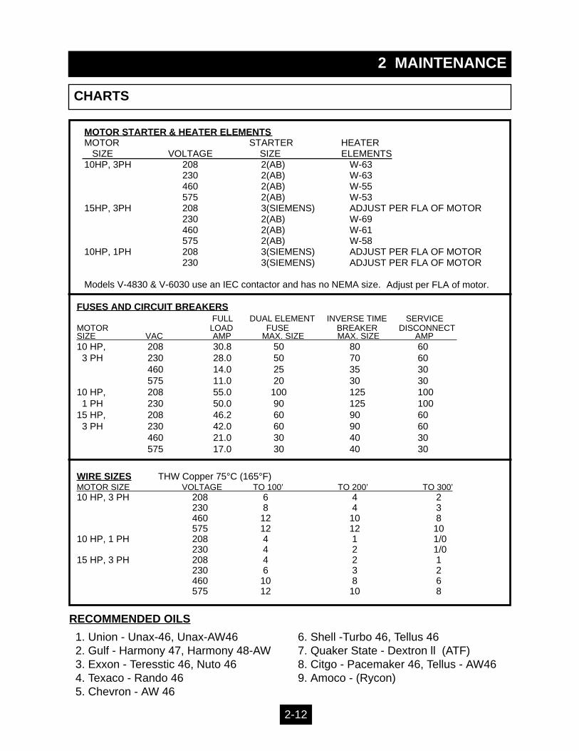
FUSES AND CIRCUIT BREAKERSFULL DUAL ELEMENT INVERSE TIME SERVICE
MOTOR LOAD FUSE BREAKER DISCONNECTSIZE VAC AMP MAX. SIZE MAX. SIZE AMP 10 HP, 208 30.8 50 80 603 PH 230 28.0 50 70 60
460 14.0 25 35 30575 11.0 20 30 30
10 HP, 208 55.0 100 125 1001 PH 230 50.0 90 125 100
15 HP, 208 46.2 60 90 603 PH 230 42.0 60 90 60
460 21.0 30 40 30575 17.0 30 40 30
WIRE SIZES THW Copper 75°C (165°F)MOTOR SIZE VOLTAGE TO 100’ TO 200’ TO 300’10 HP, 3 PH 208 6 4 2
230 8 4 3460 12 10 8575 12 12 10
10 HP, 1 PH 208 4 1 1/0230 4 2 1/0
15 HP, 3 PH 208 4 2 1230 6 3 2460 10 8 6575 12 10 8
2-12
MOTOR STARTER & HEATER ELEMENTS MOTOR STARTER HEATER SIZE VOLTAGE SIZE ELEMENTS10HP, 3PH 208 2(AB) W-63
230 2(AB) W-63460 2(AB) W-55575 2(AB) W-53
15HP, 3PH 208 3(SIEMENS) ADJUST PER FLA OF MOTOR230 2(AB) W-69460 2(AB) W-61575 2(AB) W-58
10HP, 1PH 208 3(SIEMENS) ADJUST PER FLA OF MOTOR230 3(SIEMENS) ADJUST PER FLA OF MOTOR
Models V-4830 & V-6030 use an IEC contactor and has no NEMA size.
1. Union - Unax-46, Unax-AW462. Gulf - Harmony 47, Harmony 48-AW3. Exxon - Teresstic 46, Nuto 464. Texaco - Rando 465. Chevron - AW 46
6. Shell -Turbo 46, Tellus 467. Quaker State - Dextron ll (ATF)8. Citgo - Pacemaker 46, Tellus - AW469. Amoco - (Rycon)
RECOMMENDED OILS
Adjust per FLA of motor.

2 MAINTENANCE
PARTS LIST
2-13
* After SERIAL NUMBER 127390** After SERIAL NUMBER 97723
ELECTRICAL03-0004 MOTOR, 10 HP, 3 PH (208,230,460 VAC) X X X X X X X X03-0010 LIMIT SWITCH ARM X X X X X X X03-0012 LIMIT SWITCH, 5 DEG. FREE TRAVEL X X X X X X X03-0288 TRANSFORMER (208, 230, 460 VAC) X X X X X X X X X03-0335 LIGHT, RED OMNI GLOW X X X X X X X X X03-0343 MOTOR, 15 HP, 3PH X03-0398 LEGEND, BALE MADE X X X X X X X03-0403 SOLENOID COIL FOR 02-0357 X X X X X X X X X03-0148 MOTOR STARTER, SIZE 2 AB X X X X X X X03-0486 MOTOR STARTER EXTERNAL RESET X X X X X X X X X03-0488 FUSE, 1.5 AMP X X X X X X X X X03-0498 SWITCH, MAGNETIC INTERLOCK X X X X X X X X X03-0509 LEGEND, AUTOCYCLE, 22mm X X X X X X X X X03-0510 LEGEND, MANUAL DOWN, 22mm X X X X X X X X X03-0511 LEGEND, MANUAL UP, 22mm X X X X X X X X X03-0512 LEGEND, STOP, 22mm X X X X X X X X X03-0513 LEGEND, OFF/ON, 22mm X X X X X X X X X03-0600 PRINTED CIRCUIT BOARD X X X X X X X X X03-0928 SWITCH, BLACK PUSHBUTTON, 22mm X X X X X X X X X03-0929 PUSHBUTTON, RED MUSHROOM HEAD X X X X X X X X X03-0934 SWITCH, 2 POS. KEYED SELECTOR X X X X X X X X X03-0935 KEY, FOR 03-0934 X X X X X X X X X03-0936 CONTACT 1, N.O. FOR 22mm X X X X X X X X X03-0937 CONTACT 1, N.C. FOR 22mm X X X X X X X X X03-0987 SWITCH, GREEN PUHSBUTTON, 22mm X X X X X X X X X03-1367 ENCLOSURE (PANEL BOX) X X X X X X X03-1676 MOTOR STARTER, IEC CONTACTOR X X03-1678 MOTOR STARTER, SOLID STATE X X03-1679 ENCLOSURE (PANEL BOX) X X03-1681 MOTOR STARTER, AUX. CONTACT X X99-6875 DISCONNECT CONVERSION KIT X X X X X X X
HYDRAULIC02-0050 SUCTION FILTER X X X X X X X X X02-0197 BREATHER CAP X X X X X X X X X02-0198 SIGHT GAUGE, 3 INCH X X X X X X X X X02-0214 RELIEF CARTRIDGE X X X X X X X X X02-0244 HUB COUPLING X X X X X X X X X02-0264 SUBPLATE X X X X X X X X X02-0357 VALVE, DIRECTIONAL CONTROL X X X X X X X X X02-3839 PUMP, 9 GPM, VANE X X X X X X02-1013 PUMP, 13 GPM, VANE X X X04-0260 CYL. 6 BORE, 3 ROD, 48 STROKE X X X X X X X04-0261 SEAL KIT, F/04-0260 X X X X X X X04-0500 CYL. 2.5 BORE, 18.5 STROKE X04-0520 CYL. 7 BORE, 26 STROKE X X04-0521 SEAL KIT, F/04-0520 X X
MISC. HARDWARE05-0256 WIRE, BALE TIE X X X X X X X X X05-0277 SPRING, 3/4 OD X 4 LONG X X X X X X05-0278 TURNBUCKLE, W/8" HANDWHEEL X X X X X X X05-0283 CHAIN, 2040 RIVET X X X X X X X X X05-0285 SPROCKET, F/2040 RIVET CHAIN X X X X X X X X X05-0664 MASTER LINK, F/2040 RIVET CHAIN X X X X X X X X X05-2382 CHAIN, F/EJECTOR X X05-2383 LINK F/EJECTOR CHAIN X X05-2384 TURNBUCKLE X X22-4132 FEED GATE STRIKER (BOLT IN) X X X X X X X X X
4830* 6030**4830HD 6030HD 7230HD 6030LP 6042LPPART # DESCRIPTION 4830 6030
2 MAINTENANCE
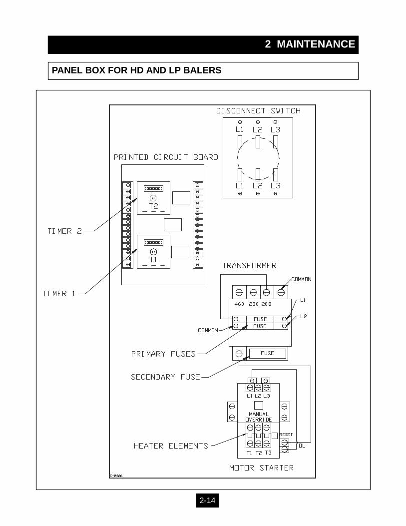
PANEL BOX FOR HD AND LP BALERS
2-14
2 MAINTENANCE
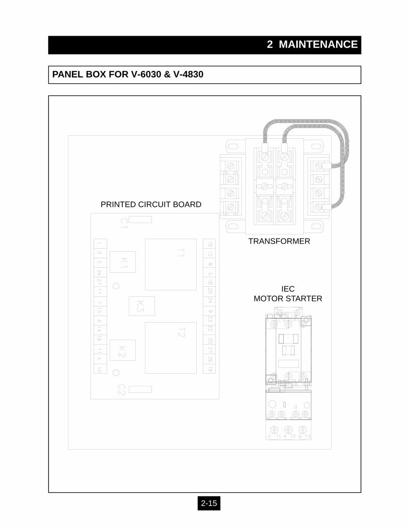
PANEL BOX FOR V-6030 & V-4830
TRANSFORMER
PRINTED CIRCUIT BOARD
IECMOTOR STARTER
2-15
2 MAINTENANCE
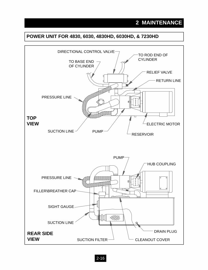
POWER UNIT FOR 4830, 6030, 4830HD, 6030HD, & 7230HD
TOP VIEW
DIRECTIONAL CONTROL VALVE
TO BASE ENDOF CYLINDER
TO ROD END OF CYLINDER
RELIEF VALVE
RETURN LINE
SUCTION LINE PUMP
ELECTRIC MOTOR
RESERVOIR
REAR SIDEVIEW
HUB COUPLING
PUMP
DRAIN PLUG
CLEANOUT COVERSUCTION FILTER
SUCTION LINE
SIGHT GAUGE
FILLER\BREATHER CAP
PRESSURE LINE
PRESSURE LINE
2-16

2 MAINTENANCE
POWER UNIT FOR 6030LP
2-17
TOP VIEW
TO BASE END-CYLINDER
TO ROD END -CYLINDER
RELIEF VALVE
RETURN LINE
PUMP
ELECTRIC MOTOR
RESERVOIR
BALER BODY
SIDE VIEW
HUB COUPLING
DRAIN PLUG
CLEANOUT COVER
SUCTION FILTER
SUCTION LINE
SIGHT GAUGE
FILLER\BREATHER CAP
PRESSURELINE
CONTROL VALVE
ELECTRIC MOTOR
RETURN LINE
DRAIN PLUG
PUMP
CONTROL VALVE
SIGHTGAUGE
PRESSURELINE
RETURN LINE
SUCTION LINE
PRESSURE LINE
TO BASE END-CYLINDER
TO ROD END -CYLINDER
2 MAINTENANCE
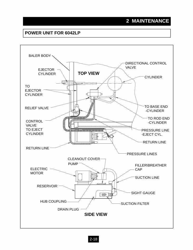
POWER UNIT FOR 6042LP
2-18
TOP VIEW
DIRECTIONAL CONTROLVALVE
TO BASE END-CYLINDER
TO ROD END -CYLINDER
RELIEF VALVE
RETURN LINE
PUMP
ELECTRIC MOTOR
RESERVOIR
PRESSURE LINE -EJECT CYL.
SIDE VIEW
HUB COUPLING
DRAIN PLUG
CLEANOUT COVER
SUCTION FILTER
SUCTION LINE
SIGHT GAUGE
FILLER\BREATHER CAP
PRESSURE LINES
CYLINDER
CONTROL VALVETO EJECTCYLINDER
EJECTORCYLINDER
TO EJECTORCYLINDER
RETURN LINE
BALER BODY
2 MAINTENANCE
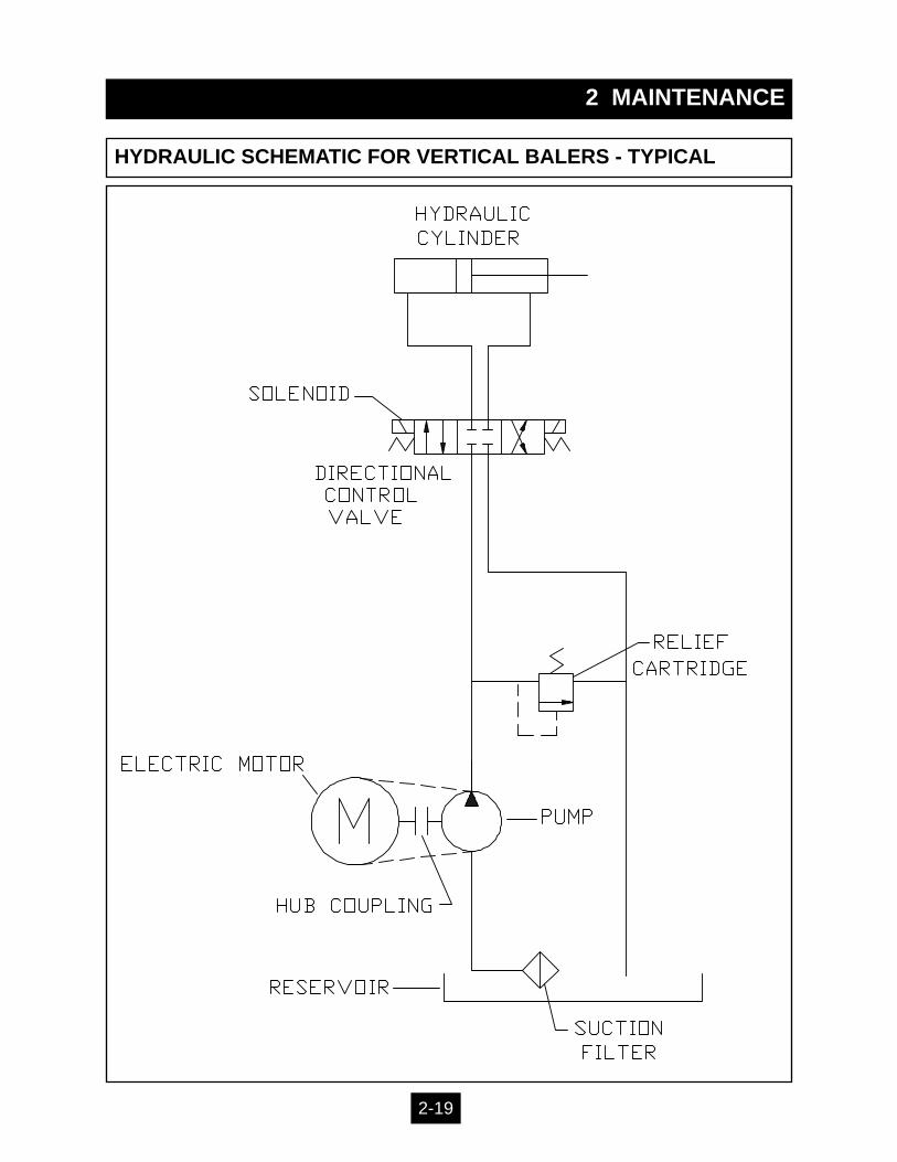
HYDRAULIC SCHEMATIC FOR VERTICAL BALERS - TYPICAL
2-19
2 MAINTENANCE
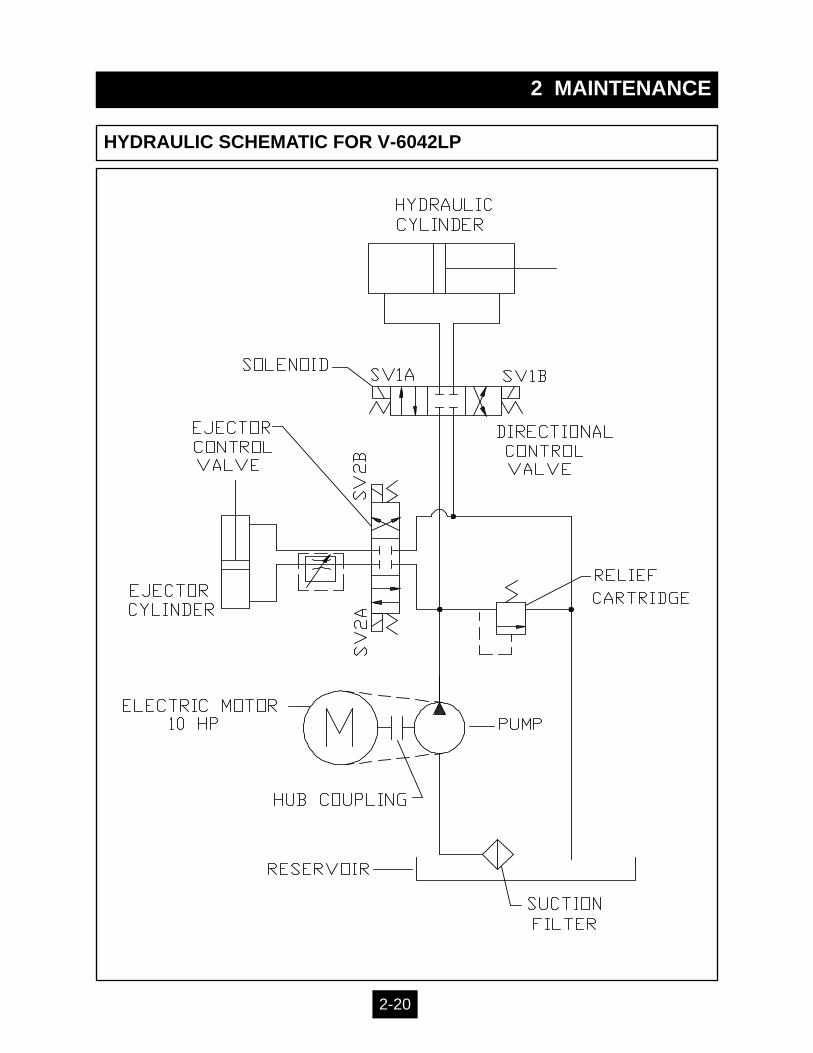
HYDRAULIC SCHEMATIC FOR V-6042LP
2-20
2 MAINTENANCE
TROUBLE-SHOOTING CHART
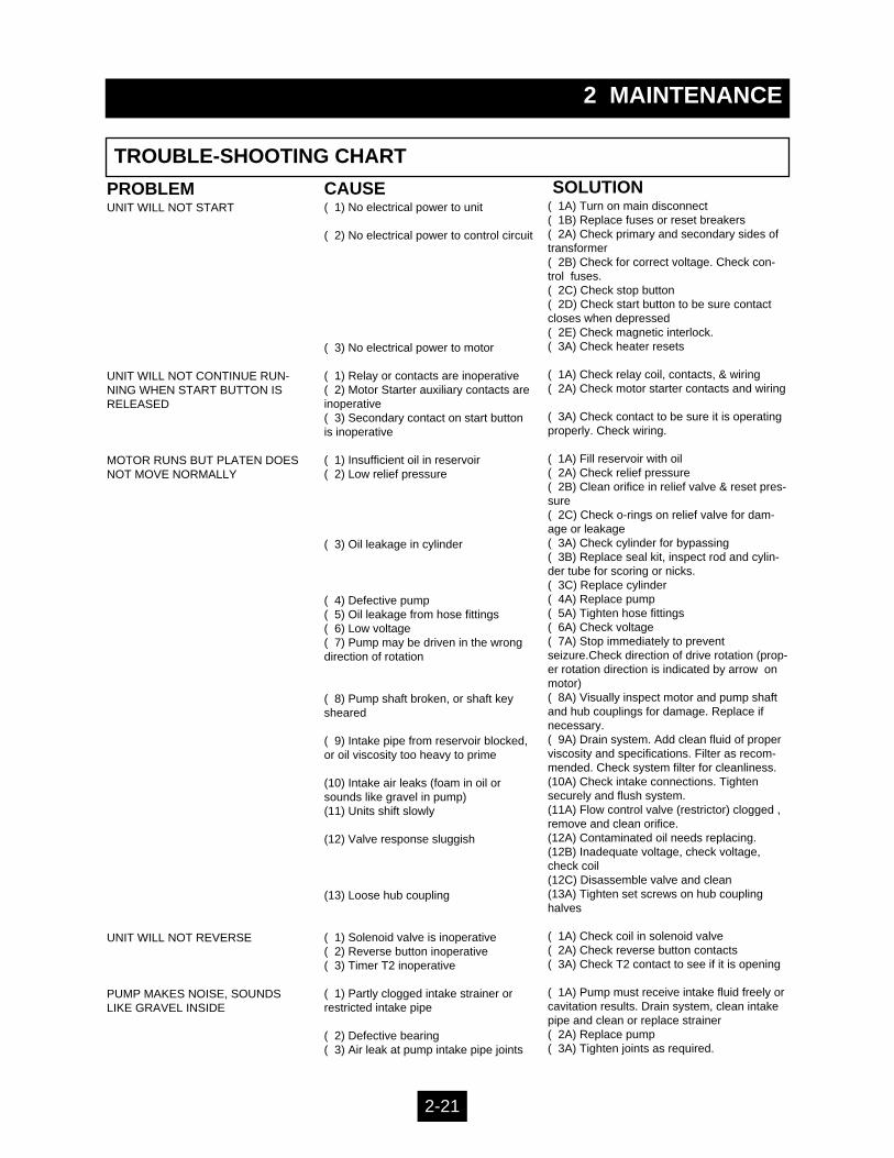
PROBLEMUNIT WILL NOT START
UNIT WILL NOT CONTINUE RUN-NING WHEN START BUTTON ISRELEASED
MOTOR RUNS BUT PLATEN DOESNOT MOVE NORMALLY
UNIT WILL NOT REVERSE
PUMP MAKES NOISE, SOUNDSLIKE GRAVEL INSIDE
CAUSE( 1) No electrical power to unit
( 2) No electrical power to control circuit
( 3) No electrical power to motor
( 1) Relay or contacts are inoperative( 2) Motor Starter auxiliary contacts areinoperative( 3) Secondary contact on start buttonis inoperative
( 1) Insufficient oil in reservoir( 2) Low relief pressure
( 3) Oil leakage in cylinder
( 4) Defective pump( 5) Oil leakage from hose fittings( 6) Low voltage( 7) Pump may be driven in the wrongdirection of rotation
( 8) Pump shaft broken, or shaft keysheared
( 9) Intake pipe from reservoir blocked,or oil viscosity too heavy to prime
(10) Intake air leaks (foam in oil orsounds like gravel in pump)(11) Units shift slowly
(12) Valve response sluggish
(13) Loose hub coupling
( 1) Solenoid valve is inoperative( 2) Reverse button inoperative( 3) Timer T2 inoperative
( 1) Partly clogged intake strainer orrestricted intake pipe
( 2) Defective bearing( 3) Air leak at pump intake pipe joints
SOLUTION( 1A) Turn on main disconnect( 1B) Replace fuses or reset breakers( 2A) Check primary and secondary sides of transformer( 2B) Check for correct voltage. Check con-trol fuses.( 2C) Check stop button( 2D) Check start button to be sure contact closes when depressed( 2E) Check magnetic interlock.( 3A) Check heater resets
( 1A) Check relay coil, contacts, & wiring( 2A) Check motor starter contacts and wiring
( 3A) Check contact to be sure it is operatingproperly. Check wiring.
( 1A) Fill reservoir with oil( 2A) Check relief pressure( 2B) Clean orifice in relief valve & reset pres-sure( 2C) Check o-rings on relief valve for dam-age or leakage( 3A) Check cylinder for bypassing( 3B) Replace seal kit, inspect rod and cylin-der tube for scoring or nicks.( 3C) Replace cylinder( 4A) Replace pump( 5A) Tighten hose fittings( 6A) Check voltage( 7A) Stop immediately to preventseizure.Check direction of drive rotation (prop-er rotation direction is indicated by arrow onmotor)( 8A) Visually inspect motor and pump shaftand hub couplings for damage. Replace ifnecessary.( 9A) Drain system. Add clean fluid of properviscosity and specifications. Filter as recom-mended. Check system filter for cleanliness.(10A) Check intake connections. Tightensecurely and flush system.(11A) Flow control valve (restrictor) clogged ,remove and clean orifice.(12A) Contaminated oil needs replacing. (12B) Inadequate voltage, check voltage, check coil(12C) Disassemble valve and clean(13A) Tighten set screws on hub coupling halves
( 1A) Check coil in solenoid valve( 2A) Check reverse button contacts( 3A) Check T2 contact to see if it is opening
( 1A) Pump must receive intake fluid freely or cavitation results. Drain system, clean intakepipe and clean or replace strainer( 2A) Replace pump( 3A) Tighten joints as required.
2-21
2 MAINTENANCE
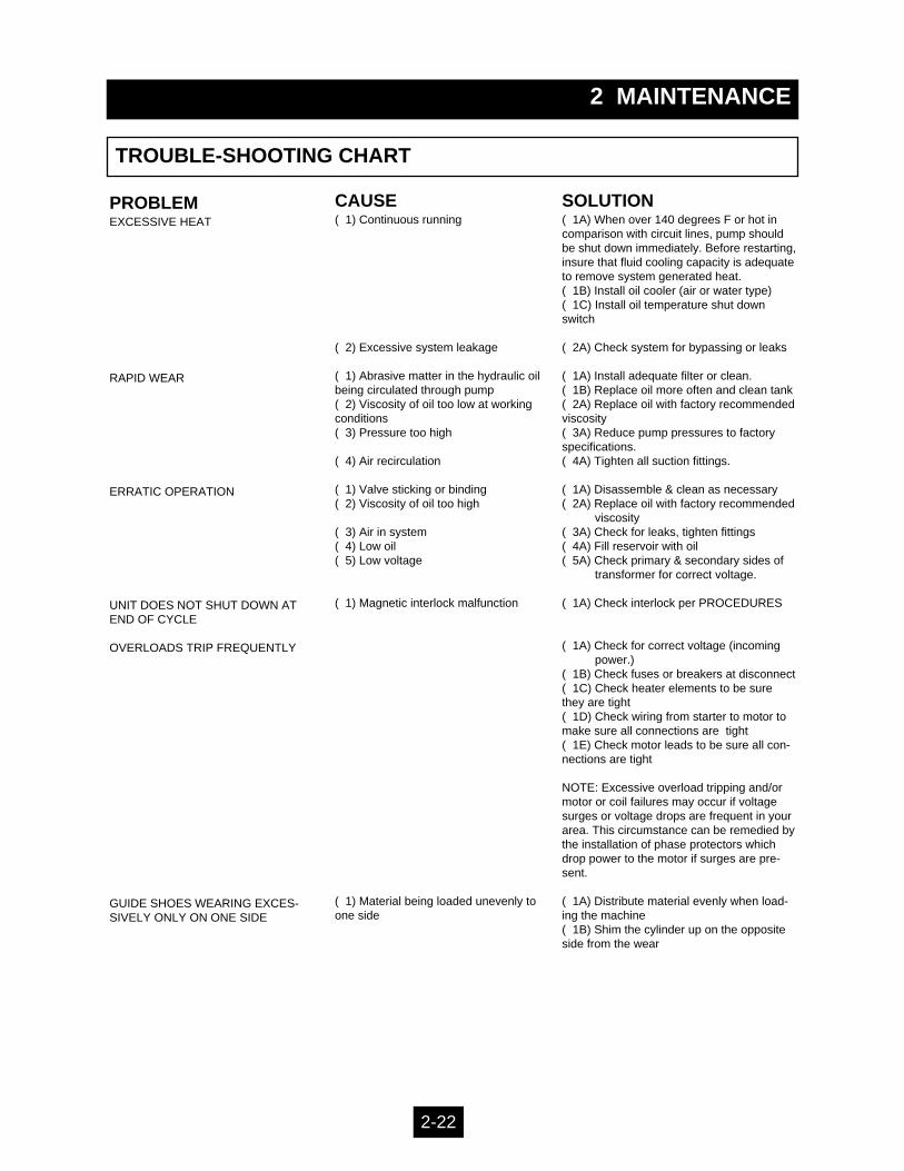
TROUBLE-SHOOTING CHART
PROBLEMEXCESSIVE HEAT
RAPID WEAR
ERRATIC OPERATION
UNIT DOES NOT SHUT DOWN ATEND OF CYCLE
OVERLOADS TRIP FREQUENTLY
GUIDE SHOES WEARING EXCES-SIVELY ONLY ON ONE SIDE
CAUSE( 1) Continuous running
( 2) Excessive system leakage
( 1) Abrasive matter in the hydraulic oilbeing circulated through pump( 2) Viscosity of oil too low at workingconditions( 3) Pressure too high
( 4) Air recirculation
( 1) Valve sticking or binding( 2) Viscosity of oil too high
( 3) Air in system( 4) Low oil( 5) Low voltage
( 1) Magnetic interlock malfunction
( 1) Material being loaded unevenly toone side
SOLUTION( 1A) When over 140 degrees F or hot incomparison with circuit lines, pump shouldbe shut down immediately. Before restarting,insure that fluid cooling capacity is adequateto remove system generated heat. ( 1B) Install oil cooler (air or water type)( 1C) Install oil temperature shut downswitch
( 2A) Check system for bypassing or leaks
( 1A) Install adequate filter or clean.( 1B) Replace oil more often and clean tank( 2A) Replace oil with factory recommended viscosity( 3A) Reduce pump pressures to factoryspecifications.( 4A) Tighten all suction fittings.
( 1A) Disassemble & clean as necessary( 2A) Replace oil with factory recommended
viscosity( 3A) Check for leaks, tighten fittings( 4A) Fill reservoir with oil( 5A) Check primary & secondary sides of
transformer for correct voltage.
( 1A) Check interlock per PROCEDURES
( 1A) Check for correct voltage (incoming power.)
( 1B) Check fuses or breakers at disconnect( 1C) Check heater elements to be surethey are tight( 1D) Check wiring from starter to motor to make sure all connections are tight( 1E) Check motor leads to be sure all con-nections are tight
NOTE: Excessive overload tripping and/ormotor or coil failures may occur if voltagesurges or voltage drops are frequent in yourarea. This circumstance can be remedied bythe installation of phase protectors whichdrop power to the motor if surges are pre-sent.
( 1A) Distribute material evenly when load-ing the machine( 1B) Shim the cylinder up on the oppositeside from the wear
2-22
3 INSTALLATION
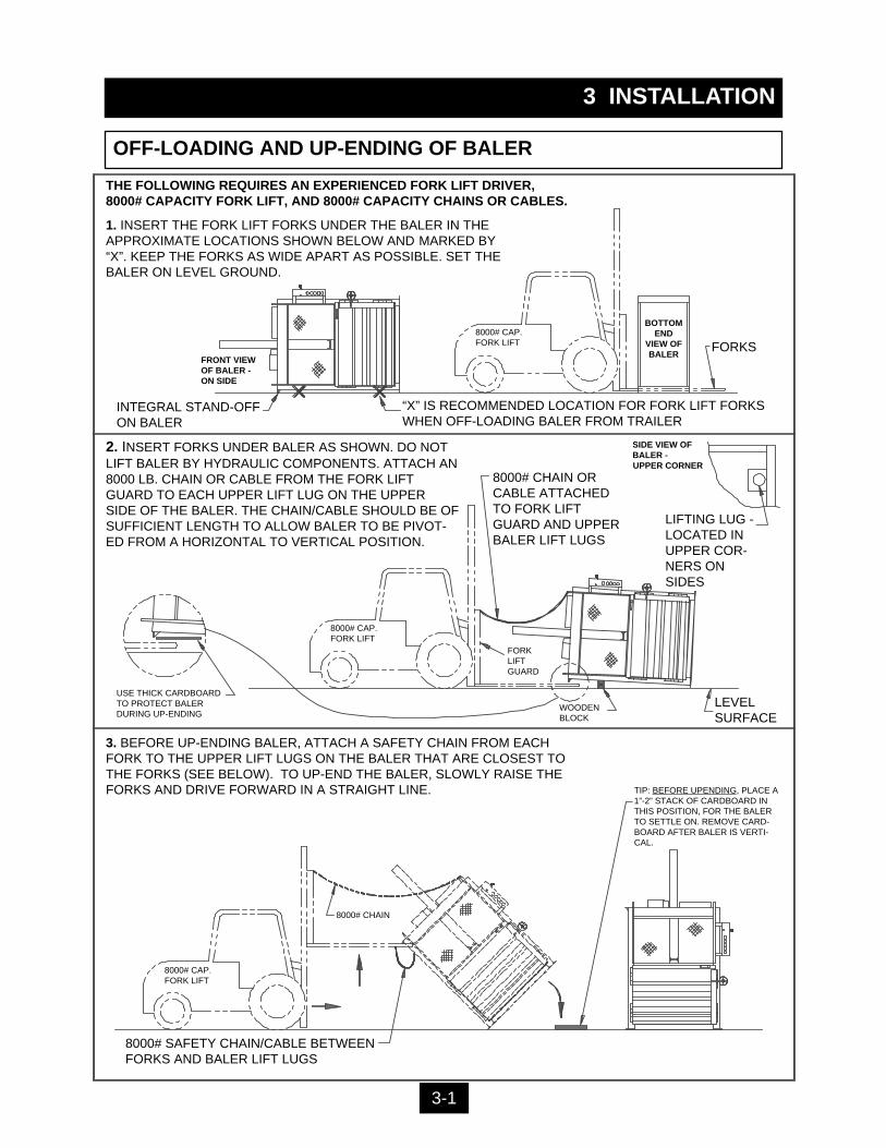
OFF-LOADING AND UP-ENDING OF BALER
1. INSERT THE FORK LIFT FORKS UNDER THE BALER IN THEAPPROXIMATE LOCATIONS SHOWN BELOW AND MARKED BY“X”. KEEP THE FORKS AS WIDE APART AS POSSIBLE. SET THEBALER ON LEVEL GROUND.
FORKS
“X” IS RECOMMENDED LOCATION FOR FORK LIFT FORKSWHEN OFF-LOADING BALER FROM TRAILER
INTEGRAL STAND-OFFON BALER
BOTTOMEND
VIEW OFBALER
8000# CAP.FORK LIFT
THE FOLLOWING REQUIRES AN EXPERIENCED FORK LIFT DRIVER, 8000# CAPACITY FORK LIFT, AND 8000# CAPACITY CHAINS OR CABLES.
FRONT VIEWOF BALER -ON SIDE
8000# CAP.FORK LIFT
LEVELSURFACE
WOODENBLOCK
SIDE VIEW OFBALER -UPPER CORNER
LIFTING LUG -LOCATED INUPPER COR-NERS ONSIDES
8000# CHAIN ORCABLE ATTACHEDTO FORK LIFTGUARD AND UPPERBALER LIFT LUGS
FORK LIFTGUARD
USE THICK CARDBOARDTO PROTECT BALERDURING UP-ENDING
2. INSERT FORKS UNDER BALER AS SHOWN. DO NOTLIFT BALER BY HYDRAULIC COMPONENTS. ATTACH AN8000 LB. CHAIN OR CABLE FROM THE FORK LIFTGUARD TO EACH UPPER LIFT LUG ON THE UPPERSIDE OF THE BALER. THE CHAIN/CABLE SHOULD BE OFSUFFICIENT LENGTH TO ALLOW BALER TO BE PIVOT-ED FROM A HORIZONTAL TO VERTICAL POSITION.
3. BEFORE UP-ENDING BALER, ATTACH A SAFETY CHAIN FROM EACHFORK TO THE UPPER LIFT LUGS ON THE BALER THAT ARE CLOSEST TOTHE FORKS (SEE BELOW). TO UP-END THE BALER, SLOWLY RAISE THEFORKS AND DRIVE FORWARD IN A STRAIGHT LINE.
8000# CHAIN
8000# SAFETY CHAIN/CABLE BETWEENFORKS AND BALER LIFT LUGS
TIP: BEFORE UPENDING, PLACE A1”-2” STACK OF CARDBOARD INTHIS POSITION, FOR THE BALERTO SETTLE ON. REMOVE CARD-BOARD AFTER BALER IS VERTI-CAL.
8000# CAP.FORK LIFT
3-1
Review this manual before beginning the installation. Study the job-site and installation requirements carefully to be certain all necessarysafeguards and/or safety devices are provided to protect all person-nel and equipment during the installation and as a completed system.
These instructions are not intended as a substitute for training and experi-ence in proper use, safety procedures, maintenance, or installation of thisequipment.
This baler is designed for INDOOR USE ONLY.
Marathon does not assume responsibility for the installation proce-dures of this equipment. Conformance to applicable local, state, andfederal laws concerning installation rests with the customer.
3 INSTALLATION
GENERAL INSTALLATION
CAUTION:
ANCHORING TO CONCRETE PADThe concrete pad should be level, and a minimum of 3000 PSI concrete,steel reinforced, 6” thick. Anchor baler to floor using anchor plates on sidesof baler base. Four 3/4” diameter anchor bolts required, Red Head typerecommended.
DECALSInstallation of the baler is not complete until an inspection of the warningdecals has been made. Decals should be clearly visible, legible, securelyapplied, and in the proper location. For decal description and location, seeDECALS and DECAL PLACEMENT in Section 1.
3-2
DANGER: DO NOT CLIMB ON SIDES OF BALER. USE A LADDER ORWORK PLATFORM WHEN WORKING ON TOP OF THE BALER OROTHER AREAS OF THE BALER THAT CAN NOT BE REACHED FROMGROUND LEVEL.
WARNING: PARTS OF THE PLATEN WILL EXTEND ABOVE THE TOPOF THE BALER WHEN THE PLATEN IS FULLY RAISED.

3 INSTALLATION
The panel box contains high voltagecomponents. Only authorized servicepersonnel should be allowed inside.See Lock-Out & Tag-Out instructions inthe Maintenance section.
ELECTRICAL INSTALLATION
WARNING: BEFORE MAKING ANY ELECTRICAL CONNECTION, BE SURETHAT THE DISCONNECT SWITCH HAS BEEN LOCKED-OUT AND TAGGED-OUTPER THE LOCK-OUT AND TAG-OUT INSTRUCTIONS ON PAGE 2-1.
1. BRANCH CIRCUIT PROTECTION IS NOT PROVIDED WITH THIS UNIT, AND MUST BE PROVIDED BY THE INSTALLER. Use the FUSE AND CIRCUIT BREAKER chart and the WIRE SIZE chart in the MAINTE-NANCE section of this manual for reference during the electrical installa-tion.
2. Before connecting power to the baler, check the incoming line voltage with a voltmeter. Also, check voltage wiring in the baler panel box. If the baler is not wired to the proper voltage, make necessary corrections before proceeding.
3. A lockable disconnect switch IS PROVIDED, in the panel box, on models V-4830HD, V-6030HD, V-7230HD, V-6030LP, and, V-6042LP, and is sizedin accordance with the baler. Three phase power should be connected to the top of this switch (a single phase option is also available). Be careful not to let incoming wires touch each other. A properly sized equipment ground wire should be connected to the enclosure ground lug.
4. A lockable disconnect switch IS NOT PROVIDED on models V-4830 & V-6030, and must be provided by the installer at the time of installation. This disconnect switch must be fussed, lockable, and within sight of, and not to exceed 50 feet from the baler, per the National Electrical Code. Additional local codes may apply.
3-3
CAUTION: All equipment should be grounded per the National Electric Code.
WARNING: BEFORE START-UP, REPLACE THE 3/4” PLUG ON THE TOP OF THEPOWER UNIT RESERVOIR WITH THE FILLER BREATHER CAP. THIS CAP ISSHIPPED INSIDE OF THE PANEL BOX.
DANGER: DO NOT CLIMB ON SIDES OF BALER. USE A LADDER WHILE PER-FORMING THE FOLLOWING PROCEDURES.
WARNING: PARTS OF THE PLATEN WILL EXTEND ABOVE THE TOP OF THEBALER WHEN THE PLATEN IS FULLY RAISED.
CAUTION: MAKE SURE PERSONS AND MATERIAL ARE CLEAR OF CHARGEBOX AREA.
1. After the electrical connections are complete, check motor rotation by the following:
a. Close bale chamber door and feed gate.b. Turn disconnect switch to the ON position.c. Have someone turn ON the keyswitch and depress the AUTO-
CYCLE button for one second and then immediately depress the EMERGENCY STOP button. Check motor rotation by watching the hub coupling through the slot in the pump-to-motor adapter. There is a rotation decal on the power unit showing correct rotation. In the event that this decal is missing, look at the hub coupling from the motor end. Rotation should be clockwise.
CAUTION: If the pump rotates backward, stop immediately!The pump will be damaged if it is operated in reverse even for short periods. Reversing any two incoming power lines will change the motor/pump rotation.
2. With the platen fully raised, check to be sure the oil reservoir is filled to the 3/4 level on the sight gauge (Refer to the maintenance chart for hydraulic oil recom-mendations). The hydraulic system pressure has been factory set.
3. The baler is equipped with an electrical interlock which prevents the use of the AUTOCYCLE and MANUAL DOWN functions when the feed gate is in the upposition. If either of these buttons start the baler when the feed gate is up, dis-continue use of the baler until repairs have been made.
4. MAKE SURE THAT THE OPERATORS ARE TRAINED IN THE PROPER USE OF THIS EQUIPMENT.
3 INSTALLATION
START-UP INSTRUCTIONS
3-4