
Operation and Maintenance Manual - Northern Pump ... manuals/Bulletin 139.pdfOperation and...
34
Operation and Maintenance Manual Northern ® 4800-15-D1776 Northern ® Pump A Division of McNally Industries, LLC 340 West Benson Avenue Grantsburg, WI 54840 Toll Free: 1-800-366-1410 Phone: 715-463-5177 Fax: 715-463-5174 www.northern-pump.com
Transcript of Operation and Maintenance Manual - Northern Pump ... manuals/Bulletin 139.pdfOperation and...

Operation and Maintenance Manual for Northern®
4800-15-D1776 Bulletin 139
REV 0.0
Operation and Maintenance Manual Northern® 4800-15-D1776
Northern® Pump
A Division of McNally Industries, LLC
340 West Benson Avenue Grantsburg, WI 54840
Toll Free: 1-800-366-1410 Phone: 715-463-5177
Fax: 715-463-5174 www.northern-pump.com

Operation and Maintenance Manual for Northern®
4800-15-D1776 Bulletin 139
REV 0.0
Table of Contents Introduction........................................................................................... 3 Cautionary Statements......................................................................... 3 Pump Installation.................................................................................. 4 Removal from Installation.................................................................... 5 Disassembly.......................................................................................... 5 Pump Disassembly Steps .................................................................... 6 Cleanup ................................................................................................. 13 Inspection.............................................................................................. 13 Assembly............................................................................................... 15 Troubleshooting Guide ........................................................................ 16 Lubrication and Preventative Maintenance........................................ 18 Appendix A – 4800-15-D1776 Exploded Diagram and Bill of Material Appendix B – D1776 Pump Unit Assembly Drawing Appendix C – Motor Data and Instruction Manual
Appendix D - Installation & Maintenance Manual Falk™ Steelflex® T20 Grid Style Coupling
Page 2 of 18

Operation and Maintenance Manual for Northern®
4800-15-D1776 Bulletin 139
REV 0.0
Introduction
The 4800 gear pump is a positive displacement, rotary pump with two gears of equal size. The pump has a constant discharge when running at a constant rotational speed. The inlet port of the pump is on the side where the gears are coming out of mesh. The discharge port is on the side of the pump where the gears are coming in to mesh. The pump transfers fluid trapped in the spaces between adjacent gear teeth and the cylinder from the inlet to the discharge side of the pump.
Inlet Discharge
Cautionary Statements Failure to heed these cautionary statements may result in personal injury and/or damage to equipment. 1. Disable and lock-out the drive system before any work is done to install, maintain, or remove the pump. 2. Fully depressurize the entire system. 3. Close and lockout the valves closest to the pump in both the suction and discharge pipe. 4. Wear protective eyewear and any other required face protection. 5. When handling corrosive, caustic, toxic, or hazardous liquids, wear protective clothing to prevent contact
with skin. 6. Wear protective footwear such as safety shoes. 7. When handling liquids with toxic vapors, wear a properly rated breathing mask. 8. Work area must be properly ventilated. 9. Work area must be properly grounded. 10. Do not work alone. 11. Clean up any spilled liquid immediately.
Page 3 of 18

Operation and Maintenance Manual for Northern®
4800-15-D1776 Bulletin 139
REV 0.0
Pump Installation 1. Turn off and lock out the drive mechanism. 3. Fully depressurize both the suction and discharge lines to the pump. 4. Close the valve in the suction and discharge lines closest to the pump. 5. Place a pan or other liquid collecting device under the pump to collect the liquid that may drain from the pump and the suction and discharge lines when connected to the pump. 6. Level and properly align pump. 7. Line pipes up naturally. Forcing pipes into place with flange bolts can draw pump out of alignment. Support pipes independently to eliminate strain on pump casing. Check alignment again and correct if necessary. 8. Pressure test inlet pipe lines for leaks and ensure that they are completely airtight. The inlet piping must have a diameter equal to, or larger than, the pump inlet port. 9. Test rotation of the motor to ensure that the pump rotates in the direction indicated by arrow on pump casing. 10. Do not subject pumps to thermal shock by exposing a cold pump to a hot liquid supply or vice versa.
Page 4 of 18

Operation and Maintenance Manual for Northern®
4800-15-D1776 Bulletin 139
REV 0.0
Removal from Installation
1. Turn off and lock out the drive mechanism. 2. Fully depressurize both the suction and discharge lines to the pump. 3. Close the valve in the suction and discharge lines closest to the pump. 4. Place a pan or other liquid collecting device under the pump to collect any liquid that may drain from the
pump or the suction and base plate when assembly is disconnected. 5. Remove the coupling hub and key from the drive shaft. Clean any residue from the drive shaft. Remove
any burrs or upset metal from the surface of the drive shaft.
Disassembly
The pump body is a series of plates held together with 4 studs (2x 12, 2x 13). The studs provide the alignment of the pump body and are precision parts. The faying surfaces of the plates are ground flat and sealed with an O-ring. Be prepared to use some force to take the pump apart. However, you are also trying to reuse as much of the pump as possible, so be careful not to damage parts unnecessarily. Before disassembly, mark the pump housing so that you will know how the parts were arranged before the pump was taken apart. A scribe line or permanent marker line along one edge and a diagonal from corner to corner works quite well. Suggested marker or scribed
lines across plates.
Page 5 of 18

Bulletin 139REV 0.0
Operation & Maintenance Manual for Northern® 4800-15-D1776 Pumps.
Pump Disassembly Steps
Remove the 2x Mounting Brackets and the 4x outer Jam Nuts (8) that secure the Mounting Brackets.
Page 6 of 18
Loosen and remove the 2x Cap Screws (4) and 2x Lock Washers (1) that retain the Bearing & Seat Housing (6).
Step
Step

Bulletin 139REV 0.0
Operation & Maintenance Manual for Northern® 4800-15-D1776 Pumps.
Remove the Bearing & Seat Housing (6) and Roller Bearing (26) by sliding them up and over the Drive Shaft (16). The Roller Bearing is pressed into the Bearing & Seat Housing. The Gasket (3) and Mechanical Seal Seat (24) may be retained in the Bearing Housing.
Remove the Mechanical Seal Head (24) by sliding it up and over the Drive Shaft (16).
Page 7 of 18
Step
Step

Bulletin 139REV 0.0
Operation & Maintenance Manual for Northern® 4800-15-D1776 Pumps.
Remove the Retaining Ring (23) that is located in the Seal Adapter Plate (11) bore on the Drive Shaft.
Loosen and remove the 2x Whole Nuts (7) and 2x Jam Nuts (8) that retain the Seal Adapter Plate (11). Remove the Seal Adapter Plate by sliding it up and over the Drive Shaft (16) and Studs (2x 12 & 2x 13).
Step
Step
Page 8 of 18

Bulletin 139REV 0.0
Operation & Maintenance Manual for Northern® 4800-15-D1776 Pumps.
Remove the Liner Plate (5) from the assembly by sliding it up and over the Drive Shaft and Studs. Note the orientation.
Remove the front Bearing Plate (15) and O-rings (10). The 2x Bearing Sleeves (20) and 4x Bearing Washers (21) will remain installed in the Bearing Plate. The Rollers (19) may fall out of the Bearing Plate. This is normal. The O-Ring on the underside of the Bearing Plate may or may not remain in the O-Ring Groove. If it is not retained, remove it at this point.
Step
Step
Page 9 of 18

Bulletin 139REV 0.0
Operation & Maintenance Manual for Northern® 4800-15-D1776 Pumps.
Remove the Drive Shaft (16) and Drive Gear (28) and remove the Driven (17) Shaft and Driven Gear (27). The shaft and gear are pressed together as one assembly.
Remove the Cylinder (2) from the assembly. At this point, the Studs may be removed. The O-Ring on the underside of the Cylinder may or may not remain in the O-Ring Groove. If it is not retained, remove it at this point.
Page 10 of 18
Step
Step

Bulletin 139REV 0.0
Operation & Maintenance Manual for Northern® 4800-15-D1776 Pumps.
Remove the rear Liner Plate (5). Note the orientation.
Remove the Rear Bearing Plate (15) and O-rings (10). The 2x Bearing Sleeves (20) and 4x Bearing Washers (21) will remain installed in the Bearing Plate. The Rollers (19) may fall out of the Bearing Plate. This is normal. The O-Ring on the underside of the Bearing plate may or may not remain in the O-Ring Groove. If it is not retained, remove it at this point. Remove the Studs and Dowels if you have not already.
Page 11 of 18
Step
Step

Bulletin 139REV 0.0
Operation & Maintenance Manual for Northern® 4800-15-D1776 Pumps.
StepSeparate the Studs (12 &13) from the End Plate (14), if not removed already. Disassembly is complete.
Page 12 of 18

Operation and Maintenance Manual for Northern®
4800-15-D1776 Bulletin 139
REV 0.0
Clean-up 1. Clean all parts of the pump in accordance with your specified cleaning procedures. Take all
appropriate precautions to prevent damage to the parts of the pump during the cleaning process. 2. All pump parts should accept a wide variety of acceptable cleaning methods and chemicals. 3. All parts of the pump may be heated to 320ºF (160 ºC). 4. Clean the flat surfaces of the pump body parts by rubbing them lightly on fine sand paper (240-320
grit) stretched or laid on a flat ground surface. Move the part in either a circular or figure eight pattern so that fine scratches are not produced across the part. Wetting the sand paper with solvent will improve the ability of the sandpaper to clean the parts.
Inspection
1. Visually inspect all parts for obvious problems, scratches on surfaces that mate with seals, cracks, upset
metal that will affect how parts mate together, burrs, or other serious wear. Correct problem or replace part as necessary.
2. Inspect the shaft and Bearing Plates for excessive grooves or other signs of severe wear in bearing
bores and gear wear surfaces. 2.1 The bearing bores must be free of major scratches and major scoring. 2.2 The lubrication groove must be clean. 3. Inspect the Drive Shaft and Gear for wear: 3.1 No burrs or upset material is allowed on the surface of the Drive Shaft that mates with the coupling. 3.2 Visually inspect the end surfaces of the gear. Major nicks, scratches, grooves, or other defects could
be a sign of imminent gear failure. 3.3 Visually inspect the outside diameter of the gear. No major nicks, scratches, grooves, or other
defects are allowed. 3.4 Visually inspect the gear teeth. The surfaces of the gear teeth must be smooth and free of obvious
wear or damage. 4. Inspect the Driven Shaft and Gear for wear: 4.1 No burrs or upset material is allowed on the surface of the Driven Shaft that mates with the Coupling. 4.2 Visually inspect the end surfaces of the gear. Major nicks, scratches, grooves, or other defects could
be a sign of imminent Gear failure.
Page 13 of 18

Operation and Maintenance Manual for Northern®
4800-15-D1776 Bulletin 139
REV 0.0
4.3 Visually inspect the outside diameter of the Gear. No major nicks, scratches, grooves, or other
defects are allowed. 4.4 Visually inspect the gear teeth. The surfaces of the gear teeth must be smooth and free of obvious
wear or damage. 5. Inspect the Cylinder for wear: 5.1 Visually inspect the end surfaces of the Cylinder. No nicks, burrs, or scratches are allowed on the
ends of the Cylinder. 5.2 Visually inspect the gear bores for any sign that the gear has contacted the surface of the gear bore.
No major nicks, scratches, grooves, or galling is allowed on the gear bore surface. If any of these conditions exist, check the gear outer diameter, shaft bearing diameter, and bearing bore diameter for wear and replace as necessary.
6. Inspect the Seal Adapter Plate: 6.1 Visually inspect the Seal Adapter Plate for nicks, scratches, or burrs on the mating surfaces. No
nicks, scratches, or burrs that will affect the mate-up of the parts at assembly or that will affect the ability of the O-ring to properly seal are allowed.
7. Inspect the Bearing & Seat housing: 7.1 Inspect the Bearing and bore. No scoring or other abnormal wear patterns are allowed. If necessary,
the Bearing may be pressed out of the Bearing Housing and replaced by pressing in a new one. 8. Inspect the O-rings: 8.1 Visually inspect the O-rings. No nicks, scratches, cuts, tears, or permanent deformation are allowed. 8.2 Inspect the O-rings for aging. The O-rings must be firm and pliable. Replacement of O-rings is
recommended whenever the pump is disassembled.
Page 14 of 18

Operation and Maintenance Manual for Northern®
4800-15-D1776 Bulletin 139
REV 0.0
Assembly 1. Visually inspect all parts for obvious problems (i.e. scratches on surfaces that mate with seals, cracks,
upset metal that will affect how parts mate together, burrs, or other serious wear). Correct problem or replace part as necessary.
2. Complete disassembly procedures in reverse order. 3. Use a light coat of a stable, pure, synthetic oil on the shafts, gear, and studs to facilitate smooth
assembly. 3. Avoid touching the polished faying surfaces of the Mechanical Seal Head (27a) and Seat (27b). 4. Torque the Whole Nuts (6) and Jam Nuts (7) to 310 foot-pounds. 5. Drive Shaft & Gear should turn freely after completion of assembly.
Page 15 of 18

Operation and Maintenance Manual for Northern®
4800-15-D1776 Bulletin 139
REV 0.0
Trouble Shooting Guide (Standard for all 4000 series pumps)
Problem Solution Key will not fit into keyway in Drive Shaft
Check for burrs and nicks in the keyway and on the key. Remove as required. Measure width of key and keyway, if an interference fit is found, reduce the width of the key.
Motor shaft turns but pump shaft does not Verify that the Coupling has been properly
installed with the correct key in each hub. Verify that the set screws are properly tightened in each coupling hub.
Pump will not prime
Check for air leaks in the suction line. Check for correct rotation of the pump shaft -- CW when facing the shaft end of the pump. “Wet” the internals of the pump with the liquid to be pumped to provide a liquid hydraulic seal in the pumping chamber. Make sure that all suction and discharge line valves are open. Make sure that the suction and discharge lines are free of obstructions.
Page 16 of 18

Operation and Maintenance Manual for Northern®
4800-15-D1776 Bulletin 139
REV 0.0
Problem Solution Pump requires too much torque
Make sure that the viscosity of the liquid being pumped is not abnormally high. Check alignment of pump.
Pumped liquid has entrained air
Check for air leaks in suction line.
Flow rate is too low
Make sure that the viscosity of the liquid being pumped is not abnormally low. Make sure that the discharge pressure is not abnormally high. Make sure that there are no air leaks in the suction line. Verify that the rotational speed is correct. Disassemble pump and verify that the internal clearances are within specification.
Page 17 of 18
Operation and Maintenance Manual for Northern®
4800-15-D1776 Bulletin 139
REV 0.0
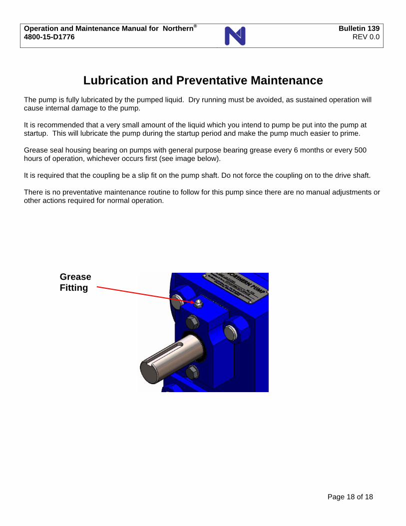
Lubrication and Preventative Maintenance The pump is fully lubricated by the pumped liquid. Dry running must be avoided, as sustained operation will cause internal damage to the pump. It is recommended that a very small amount of the liquid which you intend to pump be put into the pump at startup. This will lubricate the pump during the startup period and make the pump much easier to prime. Grease seal housing bearing on pumps with general purpose bearing grease every 6 months or every 500 hours of operation, whichever occurs first (see image below). It is required that the coupling be a slip fit on the pump shaft. Do not force the coupling on to the drive shaft. There is no preventative maintenance routine to follow for this pump since there are no manual adjustments or other actions required for normal operation.
Grease Fitting
Page 18 of 18
1 Each Side
1 Each Side
1 Each Side
15 Each Bearing Assy.
1 Each Bearing Assy.
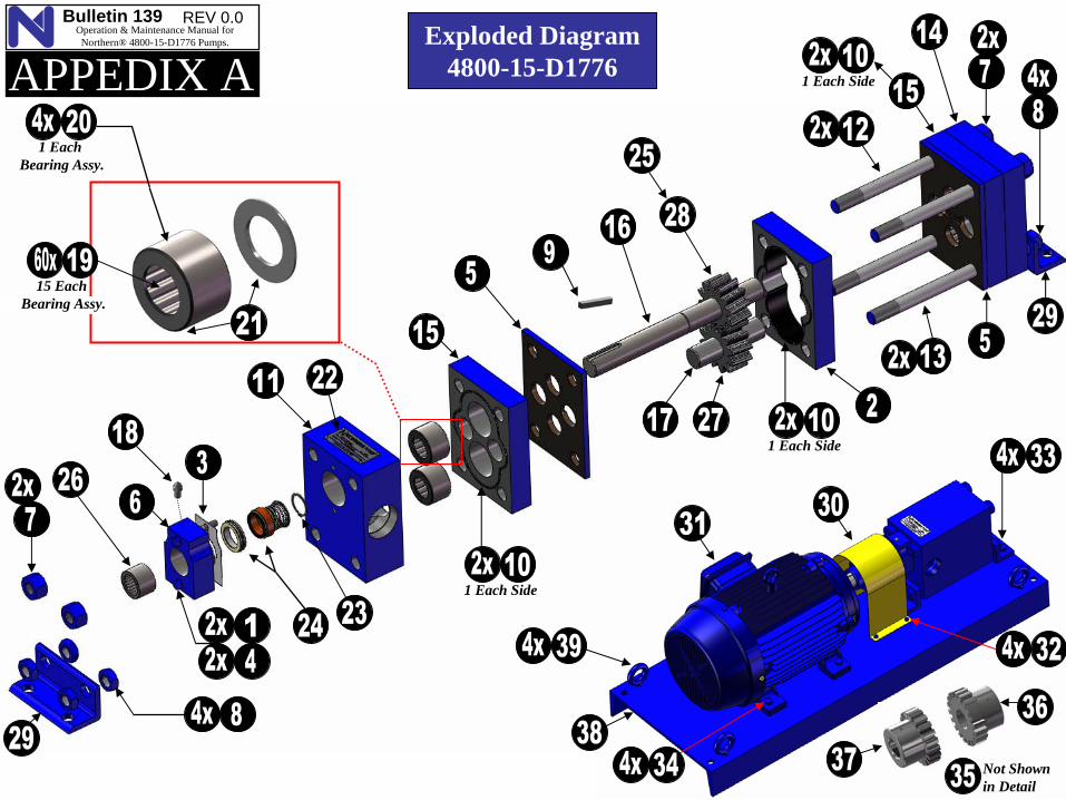
Exploded Diagram4800-15-D1776
Not Shownin Detail
Bulletin 139 REV 0.0 Operation & Maintenance Manual for Northern® 4800-15-D1776 Pumps.
APPEDIX A

FIND # ITEM NUMBER DESCRIPTION QTY
1 11490007 WASHER, LOCK 22 1174-4800-15 CYLINDER 13 1282-4800 GASKET 14 13430007-36 CAP SCREW, HEX HEAD 25 1393-4800 PLATE, LINER 26 1519-4800 HOUSING, BEARING & SEAT 17 15410014 HEAVY HEX WHOLE NUT 48 15420014 HEAVY HEX JAM NUT 89 17500006-40 END KEY 1
10 19120163-40 O'RING, ROUND SECTIONAL 611 2201-4800 PLATE, PACKING 112 28062-11 STUD, PUMP 213 28062-12 STUD, PUMP 214 3001-4800 PLATE, END 115 31342-4800 PLATE, BEARING 216 4009-4800-15 SHAFT, DRIVE 117 4080-4800-15 SHAFT, DRIVEN 118 56732 GREASE FITTING 119 5711-4800 ROLLER, BEARING 6020 5720-4800 SLEEVE, BEARING 421 5730-4800 WASHER, BEARING, OUTER 822 57455 NAMEPLATE AND PINS (4) 123 61902 RETAINING RING 124 6914-4800 MECHANICAL SEAL & SEAT, 125 70000-03 WOODRUFF KEY 126 80848 BEARING, ROLLER - Seal Support 127 8669-4800-15 PUMP GEAR, HELICAL, R.H. 128 8689-4800-15 PUMP GEAR, HELICAL, L.H. 129 7021-4800 BRACKET, MOUNTING 230 7784-4000 GUARD, COUPLING, 6.25 DROP 131 02018XP3E256T WEG ELECT. MOTOR, 20 HP 132 13430004-08 CAP SCREW, HEX HEAD CG 433 13430008-16 CAP SCREW, HEX HEAD PU 434 13430008-20 CAP SCREW, HEX HEAD MT 435 20520000 COUPLING COVER & GRID ASSY 136 20521371-06 COUPLING HUB, 50T20 - PUMP 137 20521625-06 COUPLING HUB, FALK 50T20 MOTOR 138 G-1600-9-BPL UNIT BASE (Included 4 x 39) 139 19210012-32 EYEBOLT, DROP FORGED 4
Bill of Material List - 4800-15-D1776
Bulletin 139 REV 0.0 Operation & Maintenance Manual for Northern® 4800-15-D1776 Pumps.
APPEDIX A

nsmith
Stamp
Bulletin 139 REV 0.0 Operation & Maintenance Manual for Northern® 4800-15-D1776 Pumps.
APPEDIX C
THIS SPACE INTENTIONALLY LEFT BLANK
Motor Data And Instruction ManualWEG 02018XT3E256T

Northern PumpNo.:
Date: 1/12/2012
TECHNICAL PROPOSAL
Three-phase induction motor - Squirrel cage rotor
Customer :
Product line : Three-Phase : Explosion Proof - NEMA Premium
Catalog Number : 02018XT3E256TList Price : $3,008
Notes:Three-Phase : Explosion Proof - NEMA Premium
Performed by: Checked:

Northern PumpNo.:
Date: 1/12/2012
DATA SHEETThree-phase induction motor - Squirrel cage rotor
Customer : Product line : Three-Phase : Explosion Proof - NEMA Premium
Frame : 256TOutput : 20 HPFrequency : 60 HzPoles : 4Full load speed : 1770 Slip : 1.67 %Voltage : 208-230/460 VRated current : 55.3-50.0/25.0 ALocked rotor current : 375/188 ALocked rotor current (Il/In) : 7.5No-load current : 23.6/11.8 AFull load torque : 58.5 lb.ftLocked rotor torque : 300 %Breakdown torque : 300 %Design : BInsulation class : FTemperature rise : 80 KLocked rotor time : 20 s (hot)Service factor : 1.15Duty cycle : S1Ambient temperature : -20°C - +40°CAltitude : 1000 mDegree of Protection : IP55Approximate weight : 364 lbMoment of inertia : 2.8889 sq.ft.lbNoise level : 69 dB(A)
D.E. N.D.E. Load Power factor Efficiency (%)Bearings 6309 C3 6209 Z-C3 100% 0.81 93.0Regreasing interval 20000 h 20000 h 75% 0.75 92.4Grease amount 13 g 9 g 50% 0.63 91.7
Notes:
Performed by: Checked:

Percent of rated output (%)
A -
Effi
cien
cy (%
)
B -
Pow
er fa
ctor
C - S
lipD
- Current at 230V
(A)
0 10 20 30 40 50 60 70 80 90 100 110 120 130
40
50
60
70
80
90
100
0.4
0.5
0.6
0.7
0.8
0.9
1.0 0.0
1.0
2.0
3.0
4.0
5.0
0
20
40
60
80
A
B
C
D
Northern PumpNo.:
Date: 1/12/2012
PERFORMANCE CURVES RELATED TO RATED OUTPUTThree-phase induction motor - Squirrel cage rotor
Customer : Product line : Three-Phase : Explosion Proof - NEMA Premium
Output : 20 HPFrame : 256TFull load speed : 1770 Frequency : 60 HzVoltage : 208-230/460 VInsulation class : FRated current : 55.3-50.0/25.0 A
Locked rotor current (Il/In) : 7.5Duty cycle : S1Service factor : 1.15Design : BLocked rotor torque : 300 %Breakdown torque : 300 %
Notes:
Performed by: Checked:

0.0
0.5
1.0
1.5
2.0
2.5
3.0
3.5
4.0
4.5
5.0
A
0.0
1.0
2.0
3.0
4.0
5.0
6.0
7.0
8.0
9.0
10.0
B
0 10 20 30 40 50 60 70 80 90 100Speed related to rated speed (%)
A -
Torq
ue re
late
d to
rate
d to
rque
(C/C
n)
B - C
urrent related to rated current (I/In)Northern Pump
No.:
Date: 1/12/2012
CHARACTERISTIC CURVES RELATED TO SPEEDThree-phase induction motor - Squirrel cage rotor
Customer : Product line : Three-Phase : Explosion Proof - NEMA Premium
Output : 20 HPFrame : 256TFull load speed : 1770 Frequency : 60 HzVoltage : 208-230/460 VInsulation class : FRated current : 55.3-50.0/25.0 A
Locked rotor current (Il/In) : 7.5Duty cycle : S1Service factor : 1.15Design : BLocked rotor torque : 300 %Breakdown torque : 300 %
Notes:
Performed by: Checked:

1 2 3 4 5 6 7 8
A
B
C
D
E
F
1/12/2012Three-phase induction motorFrame 256T - IP55
Notes:
Performed by:
Checked:
Customer:
Three-Phase : Explosion Proof - NEMA Premium
2E10.000
2F10.000
H0.531
BA4.250
A12.126
B11.732
C24.923
D6.250
G0.817
J2.520
K2.559
O12.352
P12.224
ES2.756
S0.375
N-W4.000
U1.625
R1.406
AB11.063
AANPT 1 1/2"
d1A 4
FlangeFD-317
AJ12.500
AK11.000
BD14.000
BF0.828
BB0.203

Bulletin 139 REV 0.0 Operation & Maintenance Manual for Northern® 4800-15-D1776 Pumps.
APPEDIX D
THIS SPACE INTENTIONALLY LEFT BLANK
Installation & Maintenance ManualFalk™ Steelflex® T20 Grid Style Coupling

How To Use This ManualThis manual provides detailed instructions on maintenance,lubrication, installation, and parts identification. Use the tableof contents below to locate required information.
Table of ContentsIntroduction . . . . . . . . . . . . . . . . . . . . . . . . . . . . . . . Page 1
Lube Fittings . . . . . . . . . . . . . . . . . . . . . . . . . . . . . . . Page 1
Limited End Float . . . . . . . . . . . . . . . . . . . . . . . . . . . Page 1
Lubrication . . . . . . . . . . . . . . . . . . . . . . . . . . . . . Pages 1-2
Installation & Alignment Instructions. . . . . . . . . . . . Pages 2-4
Annual Maintenance, Relube & Disassembly. . . . . . . . Page 4
Installation & Alignment Data . . . . . . . . . . . . . . . . . . Page 5
Parts Identification & Parts Interchangeability . . . . . . . Page 6
CAREFULLY FOLLOW THE INSTRUCTIONS IN THISMANUAL FOR OPTIMUM PERFORMANCE AND TROUBLEFREE SERVICE.
IntroductionThis manual applies to Sizes 1020T thru 1170T and 20T thru170T20 Falk SteelfIex Tapered Grid Couplings. Unlessotherwise stated, information for Sizes 1020T thru 1170Tapplies to Sizes 20T thru 170T respectively, e.g. 1020T =20T, 1100T = 100T, etc. These couplings are designed tooperate in either the horizontal or vertical position withoutmodification.
CAUTION: Consult applicable local and national safety codesfor proper guarding of rotating members. Observe all safetyrules when installing or servicing couplings. During assembly,seal keyways of vertical couplings to prevent leakage.
WARNING: Lockout starting switch of prime mover and removeall external loads from drive before installing or servicingcouplings.
Lube FittingsDepending on coupling size, cover halves have 1/8 or 3/8 NPTIube holes. Use a standard grease gun and Iube fitting asinstructed on Page 4.
Limited End FloatWhen electric motors, generators, engines, compressors, andother machines are fitted with sleeve or straight rollerbearings, limited axial end float kits are recommended forprotecting the bearings. Falk Steelflex couplings are easilymodified to limit end float; refer to Manual 428-820 forinstructions.
LubricationAdequate lubrication is essential for satisfactory operation.Page 2 provides a list of typical lubricants and specificationsfor general purpose and long term greases. Because of itssuperior lubricating characteristics and low centrifugeproperties, Falk Long Term Grease (LTG) is highly
recommended. Sizes 1020T to 1090T20 are furnished with apre-measured amount of grease for each coupling. Thegrease can be ordered for larger size couplings.
The use of general purpose grease requires re-lubrication ofthe coupling at least annually.
Long Term Grease (LTG)The high centrifugal forces encountered in couplings separatethe base oil and thickener of general purpose greases. Heavythickener, which has no lubrication qualities, accumulatesin the grid-groove area of Steelflex couplings resulting inpremature hub or grid failure unless periodic lubrication cyclesare maintained.
Falk Long Term Grease (LTG) was developed specifically forcouplings. It resists separation of the oil and thickener. Theconsistency of Falk LTG changes with operating conditions. Asmanufactured it is an NLGI #1/2 grade. Working of thelubricant under actual service conditions causes it to becomesemifluid while the grease near the seals will set to a heaviergrade, helping to prevent leakage.
LTG is highly resistant to separation, easily out performing allother lubricants tested. The resistance to separation allows thelubricant to be used for relatively long periods of time.
Steelflex couplings initially lubricated with LTG will not requirere-lubrication until the connected equipment is stopped forservicing. If a coupling leaks grease, is exposed to extremetemperatures, excessive moisture, or experiences frequentreversals, more frequent lubrication may be required.
Although LTG grease is compatible with most other couplinggreases, the mixing of greases may dilute the benefits of LTG.
USDA ApprovalLTG has the United States Department of Agriculture Food Safety& Inspection Service approval for applications where there is nopossibility of contact with edible products. (H-2 ratings).
CAUTION: Do not use LTG in bearings.
Rexnord Industries, LLC, Coupling Group 428-2105555 S. Moorland Rd., New Berlin, WI 53151-7953 USA Telephone : 262-796-4060 March 2003 (9-05 Pdf Revision)
Fax: 262-796-4064 e-mail: [email protected] web: www.rexnord.com Supersedes 11-00
Falk™ Steelflex® Couplings • Installation and Maintenance
Type T20 • Sizes 1020–1170 & 20–170 (Page 1 of 6)
TYPE T20 STEELFLEX COUPLING

Specifications — Falk LTGThe values shown are typical and slight variations arepermissible.
AMBIENT TEMPERATURE RANGE — -20°F (-29°C) to 250°F(121°C). Min. Pump = 20° F (-7° C).
MINIMUM BASE OIL VISCOSITY — 3300SSU (715cST) @100°F (38°C).
THICKENER — Lithium & soap/polymer.
CENTRIFUGE SEPARATION CHARACTERISTICS — ASTM#D4425 (Centrifuge Test) — K36 = 2/24 max., very highresistance to centrifuging.
NLGI GRADE (ASTM D-217) — 1/2
CONSISTENCY (ASTM D-217) — 60 stroke workedpenetration value in the range of 315 to 360 measured at77°F (25°C)
MINIMUM DROPPING POINT — 350°F (177°C) minimum
MINIMUM TIMKEN O.K. LOAD — 40 lbs.
ADDITIVES — Rust and oxidation inhibitors that do notcorrode steel or swell or deteriorate synthetic seals.
Packaging14 oz (0,4 kg ) CARTRIDGES — Individual or case lots of 10or 30.
35 lb (16 kg )PAIL, 120 lb (54 kg ) KEG & 400 lb (181 kg)DRUMS.
General Purpose GreaseAnnual Lubrication — The following specifications andlubricants for general purpose grease apply to Falk Steelflexcouplings that are lubricated annually and operate withinambient temperatures of 0°F to 150°F (-18°C to 66°C). Fortemperatures beyond this range (see Table 1), refer to Falk.
If a coupling leaks grease, is exposed to extremetemperatures, excessive moisture, or experiences frequentreversals, more frequent lubrication may be required.
Specifications — General Purpose CouplingLubricantsThe values shown are typical and slight variations arepermissible.
DROPPING POINT — 300°F (149°C) or higher.
CONSISTENCY — NLGI No. 2 with 60 stroke workedpenetration value in the range of 250 to 300.
SEPARATION AND RESISTANCE — Low oil separation rateand high resistance to separation from centrifuging.
LIQUID CONSTITUENT — Possess good lubricatingproperties equivalent to a high quality, well refined petroleumoil.
INACTIVE — Must not corrode steel or cause swelling ordeterioration of synthetic seals.
CLEAN — Free from foreign inclusions.
General Purpose Greases Meeting FalkSpecificationsLubricants listed below are typical products only and shouldnot be construed as exclusive recommendations.
Installation Of Type T20 Steelflex TaperedGrid Couplings
InstallationOnly standard mechanics tools, wrenches, a straight edge,and feeler gauges are required to install Falk Steelflexcouplings. Clean all parts using a non-flammable solvent.Check hubs, shafts and keyways for burrs. Coupling Sizes1020T thru 1090T are generally furnished for CLEARANCEFIT with setscrew over the keyway. Sizes 1100T and larger arefurnished for an INTERFERENCE FIT without a setscrew.
CLEARANCE FIT HUBS — Clean all parts using anon-flammable solvent. Check hubs, shafts, and keyways forburrs. Do not heat clearance fit hubs. Install keys, mount hubswith flange face flush with shaft ends or as otherwise specifiedand tighten setscrews.
INTERFERENCE FIT HUBS — Furnished without setscrews. Heathubs to a maximum of 275°F (135°C) using an oven, torch,induction heater, or an oil bath. To prevent seal damage, DONOT heat hubs beyond a maximum temperature of 400°F(205°C).
When an oxy-acetylene or blow torch is used, use an excessacetylene mixture. Mark hubs near the center of their length inseveral places on hub body with a temperature sensitivecrayon, 275°F (135°C) melt temperature. Direct flame towardshub bore using constant motion to avoid overheating an area.
Rexnord Industries, LLC, Coupling Group428-2105555 S. Moorland Rd., New Berlin, WI 53151-7953 USA Telephone : 262-796-4060March 2003 (9-05 Pdf Revision)
Fax: 262-796-4064 e-mail: [email protected] web: www.rexnord.comSupersedes 11-00
Installation and Maintenance • Falk™ Steelflex® Couplings
(Page 2 of 6) Type T20 • Sizes 1020–1170 & 20–170
TABLE 1 — General Purpose Greases �
Ambient TemperatureRange
0°F to 150°F(-18°C to 66°C)
-30°F to 100°F(-34°C to 38°C)
Manufacturer Lubricant † Lubricant †
Amoco Oil Co. Amolith Grease #2 Amolith Grease #2BP Oil Co. Energrease LS-EP2 Energrease LS-EP1Chevron U.S.A. Inc. Dura-Lith EP2 Dura-Lith EP1Citgo Petroleum Corp. Premium Lithium Grease EP2 Premium Lithium Grease EP1Conoco Inc. EP Conolith Grease #2 EP Conolith Grease #2
Exxon Company, USA Unirex EP2 Unirex EP2E.F. Houghton & Co. Cosmolube 2 Cosmolube 1Imperial Oil Ltd. Unirex EP2 Unirex EP2Kendall Refining Co. Lithium Grease L421 Lithium Grease L421
Keystone Div. (Pennwalt) 81 EP-2 81 EP-1Lyondell Petrochemical(ARCO)
Litholine H EP 2 Grease Litholine H EP 2 Grease
Mobil Oil Corp. Mobilux EP111 Mobilith AW1Petro-Canada Products Multipurpose EP2 Multipurpose EP1
Phillips 66 Co. Philube Blue EP Philube Blue EPShell Oil Co. Alvania Grease 2 Alvania Grease 2Shell Canada Ltd. Alvania Grease 2 Alvania Grease 2Sun Oil Co. Ultra Prestige 2EP Ultra Prestige 2EP
Texaco Lubricants Starplex HD2 Multifak EP2Unocal 76 (East & West) Unoba EP2 Unoba EP2Valvoline Oil Co. Multilube Lithium EP Grease . . .
� Grease application or re-lubrication should be done at temperatures above 20°F(-7°C). If grease must be applied below 20°F (-7°C), consult the Factory.
† Lubricants listed may not be suitable for use in the food processing industry; checkwith lube manufacturer for approved lubricants.

WARNING: If an oil bath is used, the oil must have a flashpoint of 350°F (177°C) or higher. Do not rest hubs on thebottom of the container. Do not use an open flame in acombustible atmosphere or near combustible materials.
Heat hubs as instructed above. Mount hubs as quickly as possiblewith hub face flush with shaft end. Allow hubs to cool beforeproceeding. Insert setscrews (if required) and tighten.
Maximize Performance And LifeThe performance and life of couplings depend largely uponhow you install and maintain them. Before installingcouplings, make certain that foundations of equipment to beconnected meet manufacturers’ requirements. Check for softfoot. The use of stainless steel shims is recommended.Measuring misalignment and positioning equipment withinalignment tolerances is simplified with an alignment computer.These calculations can also be done graphically ormathematically.
Alignment is shown using spacer bar and straight edge. Thispractice has proven to be adequate for many industrialapplications. However, for superior final alignment, the use ofdial indicators (see Manual 458-834 for instructions), lasers,alignment computers, or graphical analysis is recommended.
1— Mount Covers, Seals & Hubs
Lock out starting switch of prime mover. Clean all metal partsusing a non-flammable solvent. Place seals into each cover halfand lightly coat seals with grease. Place covers on shafts BEFOREmounting hubs. Heat interference fit hubs as previously instructed.Seal keyways to prevent leakage. Mount hubs on their respectiveshafts so the hub face is flush with the end of its shaft unlessotherwise indicated. Tighten setscrews when furnished.
2 — Gap & Angular Alignment
Use a spacer bar equal in thickness to the gap specified inTable 2, Page 5. Insert bar as shown below left, to same depthat 90° intervals and measure clearance between bar and hubface with feelers. The difference in minimum and maximummeasurements must not exceed the ANGULAR installationlimits specified in Table 2.
3 — Offset Alignment
Align so that a straight edge rests squarely (or within the limitsspecified in Table 2) on both hubs as shown above and also at90° intervals. Check with feelers. The clearance must notexceed the PARALLEL OFFSET installation limits specified inTable 2. Tighten all foundation bolts and repeat Steps 2 and3. Realign coupling if necessary.
4 — Insert Grid
Insert gasket thru the gap and hang it on either hub. Pack gapand grooves with specified lubricant before inserting grid. Whengrids are furnished in two or more segments, install them so thatall cut ends extend in the same direction (as detailed in theexploded view picture above); this will assure correct grid contactwith non-rotating pin in cover halves. Spread the grid slightly topass over the coupling teeth and seat with a soft mallet.
Rexnord Industries, LLC, Coupling Group 428-2105555 S. Moorland Rd., New Berlin, WI 53151-7953 USA Telephone : 262-796-4060 March 2003 (9-05 Pdf Revision)
Fax: 262-796-4064 e-mail: [email protected] web: www.rexnord.com Supersedes 11-00
Falk™ Steelflex® Couplings • Installation and Maintenance
Type T20 • Sizes 1020–1170 & 20–170 (Page 3 of 6)

5 — Pack With Grease & Assemble Covers
Pack the spaces between and around the grid with as muchlubricant as possible and wipe off excess flush with top of grid.Make certain lube plugs are removed to ease in coverassembly. Slide cover halves with seals onto hubs and positionwith lube holes 180° apart (90° apart for Sizes 1150 thru1170). Line up cover and gasket bolt holes and secure withfasteners; tighten to torque specified in Table 2. CAUTION:
Make certain lube plugs are installed before operating.
Annual MaintenanceFor extreme or unusual operating conditions, check couplingmore frequently.
1. Check alignment per steps on Page 3. If the maximumoperating misalignment limits are exceeded, realign thecoupling to the recommended installation limits. See Table2 for installation and operating alignment limits.
2. Check tightening torques of all fasteners.
3. Inspect seal ring and gasket to determine if replacement isrequired. If leaking grease, replace.
4. When connected equipment is serviced, disassemble thecoupling and inspect for wear. Replace worn parts. Cleangrease from coupling and repack with new grease. Installcoupling using new gasket as instructed in this manual.
Periodic Lubrication
The required frequency of lubrication is directly related to the typeof lubricant chosen, and the operating conditions. Steelflexcouplings lubricated with common industrial lubricants, such asthose shown in Table 1, should be relubed annually. The use ofFalk Long Term Grease (LTG) will allow relube intervals to beextended to beyond five years. When relubing, remove both lubeplugs and insert lube fitting. Fill with recommended lubricant untilan excess appears at the opposite hole. CAUTION: Makecertain all plugs have been inserted after lubricating.
Coupling Disassembly & Grid Removal
Whenever it is necessary to disconnect the coupling, removethe cover halves and grid. A round rod or screwdriver that willconveniently fit into the open loop ends of the grid is required.Begin at the open end of the grid section and insert the rod orscrewdriver into the loop ends. Use the teeth adjacent to eachloop as a fulcrum and pry the grid out radially in even,gradual stages, proceeding alternately from side to side.
Rexnord Industries, LLC, Coupling Group428-2105555 S. Moorland Rd., New Berlin, WI 53151-7953 USA Telephone : 262-796-4060March 2003 (9-05 Pdf Revision)
Fax: 262-796-4064 e-mail: [email protected] web: www.rexnord.comSupersedes 11-00
Installation and Maintenance • Falk™ Steelflex® Couplings
(Page 4 of 6) Type T20 • Sizes 1020–1170 & 20–170

Type T Coupling Installation & AlignmentDataMaximum life and minimum maintenance for the coupling andconnected machinery will result if couplings are accuratelyaligned. Coupling life expectancy between initial alignmentand maximum operating limits is a function of load, speedand lubrication. Maximum operating values listed in Table 2are based on cataloged allowable rpm.
Values listed are based upon the use of the gaps listed,standard coupling components, standard assemblies, andcataloged allowable speeds.
Values may be combined for an installation or operating condition.
Example: 1060T max. operating misalignment is .016"parallel plus .018" angular.
NOTE: For applications requiring greater misalignment, referapplication details to the Factory.
Angular misalignment is dimension X minus Y as illustrated below.
Parallel misalignment is distance P between the hub centerlines as illustrated below.
End float (with zero angular and parallel misalignment) is the axialmovement of the hubs(s) within the cover(s) measured from “O” gap.
Rexnord Industries, LLC, Coupling Group 428-2105555 S. Moorland Rd., New Berlin, WI 53151-7953 USA Telephone : 262-796-4060 March 2003 (9-05 Pdf Revision)
Fax: 262-796-4064 e-mail: [email protected] web: www.rexnord.com Supersedes 11-00
Falk™ Steelflex® Couplings • Installation and Maintenance
Type T20 • Sizes 1020–1170 & 20–170 (Page 5 of 6)
GAP
Y
X
F F
ANGULAR MISALIGNMENT
P
P
PARALLEL OFFSET MISALIGNMENT END FLOAT
TABLE 2 — Misalignment & End Float
SIZE
Installation Limits Operating LimitsCover Fastener
TighteningTorque Values
AllowSpeed(rpm)
Lube WtParallelOffset-P
Angular(x-y)
Hub Gap� 10%
ParallelOffset-P
Angular(x-y)
End FloatPhysical Limit
(Min) 2 x F
MaxInch
Maxmm
MaxInch
Maxmm
Inch mmMaxInch
Maxmm
MaxInch
Maxmm
Inch mm (lb-in) (Nm) lb kg
1020T .006 0,15 .003 0,08 .125 3 .012 0,30 .010 0,25 .186 4,72 100 11,3 6000 .06 0,031030T .006 0,15 .003 0,08 .125 3 .012 0,30 .012 0,30 .186 4,72 100 11,3 6000 .09 0,041040T .006 0,15 .003 0,08 .125 3 .012 0,30 .013 0,33 .186 4,72 100 11,3 6000 .12 0,051050T .008 0,20 .004 0,10 .125 3 .016 0,41 .016 0,41 .186 4,72 200 23,6 6000 .15 0,07
1060T .008 0,20 .005 0,13 .125 3 .016 0,41 .018 0,46 .220 5,59 200 22,6 6000 .19 0,091070T .008 0,20 .005 0,13 .125 3 .016 0,41 .020 0,51 .220 5,59 200 22,6 5500 .25 0,111080T .008 0,20 .006 0,15 .125 3 .016 0,41 .024 0,61 .282 7,16 200 22,6 4750 .38 0,171090T .008 0,20 .007 0,18 .125 3 .016 0,41 .028 0,71 .282 7,16 200 22,6 4000 .56 0,25
1100T .010 0,25 .008 0,20 .188 5 .020 0,51 .033 0,84 .408 10,36 260 29,4 3250 .94 0,431110T .010 0,25 .009 0,23 .188 5 .020 0,51 .036 0,91 .408 10,36 260 29,4 3000 1.1 0,511120T .011 0,28 .010 0,25 .250 6 .022 0,56 .040 1,02 .546 13,87 260 29,4 2700 1.6 0,741130T .011 0,28 .012 0,30 .250 6 .022 0,56 .047 1,19 .548 13,92 650 73,4 2400 2.0 0,91
1140T .011 0,28 .013 0,33 .250 6 .022 0,56 .053 1,35 .568 14,43 650 73,4 2200 2.5 1,141150T .012 0,30 .016 0,41 .250 6 .024 0,61 .062 1,57 .620 15,75 650 146 2000 4.2 1,911160T .012 0,30 .018 0,46 .250 6 .024 0,61 .070 1,78 .630 16,00 1300 146 1750 6.2 2,811170T .012 0,30 .020 0,51 .250 6 .024 0,61 .079 2,01 .630 16,00 1300 146 1600 7.7 3,49

Parts IdentificationAll coupling parts have identifying part numbers as shownbelow. Parts 3 and 4 (Hubs and Grids), are the same for bothType T10 and T20 couplings. All other coupling parts are unique toType T20. When ordering parts, always SPECIFY SIZE and TYPEshown on the COVER.
Parts InterchangeabilityParts are interchangeable between Sizes 20T and 1020T, 30Tand 1030T, etc. except as noted.
GRIDS — Size 1020T thru 1140T Steelflex couplings use bluegrids or non-painted grids. Older models, 20T thru 140T, useorange grids.
CAUTION: Blue grids may be used in all applications, but DONOT substitute orange grids for blue.
Rexnord Industries, LLC, Coupling Group428-2105555 S. Moorland Rd., New Berlin, WI 53151-7953 USA Telephone : 262-796-4060March 2003 (9-05 Pdf Revision)
Fax: 262-796-4064 e-mail: [email protected] web: www.rexnord.comSupersedes 11-00
Installation and Maintenance • Falk™ Steelflex® Couplings
(Page 6 of 6) Type T20 • Sizes 1020–1170 & 20–170
PART DESCRIPTION1. Seal (T20)
2. Cover (T20)
3. Hub (Specify boreand keyway)
4. Grid
5. Gasket (T20)
6. Fasteners (T20) — Couplingmay be supplied with oneset each of inch seriesfasteners and metricfasteners.
7. Lube Plug
ORDER INFORMATION1. Identify part(s) required by
name above.
2. Furnish the followinginformation.
EXAMPLE:Coupling Size: 1030Coupling Type: T20Model: BBore: 1.375Keyway: .375 x .187
3. Price parts from appropriateprice list and discount sheet.
PART NUMBER LOCATION
SIZESIZE &PARTNUMBER
SIZE, PART NUMBER& BORE
1
23 4
3
5 2
1
6
7