Operation and Maintenance Manual - MudPuppy
144
SAFETY.CAT.COM Operation and Maintenance Manual C7.1 Industrial Engine 881 1-Up (Engine) SEBU8733-01 September 2013
Transcript of Operation and Maintenance Manual - MudPuppy

SAFETY.CAT.COM
Operation andMaintenanceManualC7.1 Industrial Engine881 1-Up (Engine)
SEBU8733-01September 2013

Important Safety InformationMost accidents that involve product operation, maintenance and repair are caused by failure to observebasic safety rules or precautions. An accident can often be avoided by recognizing potentially hazardoussituations before an accident occurs. A person must be alert to potential hazards, including human factorsthat can affect safety. This person should also have the necessary training, skills and tools to perform thesefunctions properly.
Improper operation, lubrication, maintenance or repair of this product can be dangerous and couldresult in injury or death.
Do not operate or perform any lubrication,maintenance or repair on this product, until you verifythat you are authorized to perform this work, and have read and understood the operation,lubrication, maintenance and repair information.
Safety precautions and warnings are provided in this manual and on the product. If these hazard warningsare not heeded, bodily injury or death could occur to you or to other persons.
The hazards are identified by the “Safety Alert Symbol” and followed by a “Signal Word” such as“DANGER”, “WARNING” or “CAUTION”. The Safety Alert “WARNING” label is shown below.
The meaning of this safety alert symbol is as follows:
Attention! Become Alert! Your Safety is Involved.
The message that appears under the warning explains the hazard and can be either written or pictoriallypresented.
A non-exhaustive list of operations that may cause product damage are identified by “NOTICE” labels onthe product and in this publication.
Caterpillar cannot anticipate every possible circumstance that might involve a potential hazard.The warnings in this publication and on the product are, therefore, not all inclusive. You must notuse this product in any manner different from that considered by this manual without first satisfyingyourself that you have considered all safety rules and precautions applicable to the operation of theproduct in the location of use, including site-specific rules and precautions applicable to theworksite. If a tool, procedure, work method or operating technique that is not specificallyrecommended by Caterpillar is used, you must satisfy yourself that it is safe for you and for others.You should also ensure that you are authorized to perform this work, and that the product will not bedamaged or become unsafe by the operation, lubrication, maintenance or repair procedures thatyou intend to use.
The information, specifications, and illustrations in this publication are on the basis of information that wasavailable at the time that the publication was written. The specifications, torques, pressures,measurements, adjustments, illustrations, and other items can change at any time. These changes canaffect the service that is given to the product. Obtain the complete and most current information before youstart any job. Cat dealers have the most current information available.
When replacement parts are required for thisproduct Caterpillar recommends using Cat re-placement parts.
Failure to follow this warning may lead to pre-mature failures, product damage, personal in-jury or death.
In the United States, the maintenance, replacement, or repair of the emission control devices andsystemsmay be performed by any repair establishment or individual of the owner's choosing.
i05296198

Table of Contents
Foreword.............................. ............................. 4
Safety Section
Safety Messages....................... ....................... 5
General Hazard Information ............... .............. 8
Burn Prevention....................... ....................... 12
Fire Prevention and Explosion Prevention ... .. 13
Crushing Prevention and Cutting Prevention . 15
Mounting and Dismounting............... .............. 15
High Pressure Fuel Lines ................ ............... 15
Before Starting Engine ................. .................. 17
Engine Starting........................ ....................... 17
Engine Stopping ....................... ...................... 18
Electrical System...................... ...................... 18
Engine Electronics..................... ..................... 19
Product InformationSection
General Information.................... .................... 21
Product Identification Information.......... ......... 30
Operation Section
Lifting and Storage..................... ..................... 33
Features and Controls .................. .................. 37
Engine Diagnostics..................... .................... 59
Engine Starting........................ ....................... 64
Engine Operation...................... ...................... 67
Cold Weather Operation................. ................ 69
Engine Stopping ....................... ...................... 74
MaintenanceSection
Refill Capacities....................... ....................... 76
Maintenance Recommendations.......... .......... 83
Maintenance Interval Schedule ........... ........... 87
Warranty Section
Warranty Information .................. .................. 131
Reference InformationSection
Engine Ratings ....................... ...................... 132
Customer Service ..................... .................... 133
ReferenceMaterials .................. ................... 135
Index Section
Index............................... .............................. 138
SEBU8733 3Table of Contents

Foreword
Literature InformationThis manual contains safety, operation instructions,lubrication and maintenance information. This manualshould be stored in or near the engine area in aliterature holder or literature storage area. Read,study and keep it with the literature and engineinformation.
English is the primary language for all Catpublications. The English used facilitates translationand consistency in electronic media delivery.
Some photographs or illustrations in this manualshow details or attachments that may be differentfrom your engine. Guards and covers may have beenremoved for illustrative purposes. Continuingimprovement and advancement of product designmay have caused changes to your engine which arenot included in this manual. Whenever a questionarises regarding your engine, or this manual, pleaseconsult with your Cat dealer for the latest availableinformation.
SafetyThis safety section lists basic safety precautions. Inaddition, this section identifies hazardous, warningsituations. Read and understand the basicprecautions listed in the safety section beforeoperating or performing lubrication, maintenance andrepair on this product.
OperationOperating techniques outlined in this manual arebasic. They assist with developing the skills andtechniques required to operate the engine moreefficiently and economically. Skill and techniquesdevelop as the operator gains knowledge of theengine and its capabilities.
The operation section is a reference for operators.Photographs and illustrations guide the operatorthrough procedures of inspecting, starting, operatingand stopping the engine. This section also includes adiscussion of electronic diagnostic information.
MaintenanceThe maintenance section is a guide to engine care.The illustrated, step-by-step instructions are groupedby fuel consumption, service hours and/or calendartime maintenance intervals. Items in the maintenanceschedule are referenced to detailed instructions thatfollow.
Use fuel consumption or service hours to determineintervals. Calendar intervals shown (daily, annually,etc.) may be used instead of service meter intervals ifthey provide more convenient schedules andapproximate the indicated service meter reading.
Recommended service should be performed at theappropriate intervals as indicated in the MaintenanceInterval Schedule. The actual operating environmentof the engine also governs the Maintenance IntervalSchedule. Therefore, under extremely severe, dusty,wet or freezing cold operating conditions, morefrequent lubrication and maintenance than isspecified in the Maintenance Interval Schedule maybe necessary.
The maintenance schedule items are organized for apreventive maintenance management program. If thepreventive maintenance program is followed, aperiodic tune-up is not required. The implementationof a preventive maintenance management programshould minimize operating costs through costavoidances resulting from reductions in unscheduleddowntime and failures.
Maintenance IntervalsPerformmaintenance on items at multiples of theoriginal requirement. Each level and/or individualitems in each level should be shifted ahead or backdepending upon your specific maintenance practices,operation and application. We recommend that themaintenance schedules be reproduced and displayednear the engine as a convenient reminder. We alsorecommend that a maintenance record be maintainedas part of the engine's permanent record.
See the section in the Operation and MaintenanceManual, “Maintenance Records” for informationregarding documents that are generally accepted asproof of maintenance or repair. Your authorized Catdealer can assist you in adjusting your maintenanceschedule to meet the needs of your operatingenvironment.
OverhaulMajor engine overhaul details are not covered in theOperation and Maintenance Manual except for theinterval and the maintenance items in that interval.Major repairs are best left to trained personnel or anauthorized Cat dealer. Your Cat dealer offers avariety of options regarding overhaul programs. If youexperience a major engine failure, there are alsonumerous after failure overhaul options availablefrom your Cat dealer. Consult with your dealer forinformation regarding these options.
California Proposition 65 WarningDiesel engine exhaust and some of its constituentsare known to the State of California to cause cancer,birth defects, and other reproductive harm.
Battery posts, terminals and related accessoriescontain lead and lead compounds.Wash hands afterhandling.
4 SEBU8733Foreword
Safety Sectioni04889628
Safety MessagesSMCS Code: 1000; 7405
There may be several specific warning signs on yourengine. The exact location and a description of thewarning signs are reviewed in this section. Pleasebecome familiar with all warning signs.
Ensure that all of the warning signs are legible. Cleanthe warning signs or replace the warning signs if thewords cannot be read or if the illustrations are notvisible. Use a cloth, water, and soap to clean thewarning signs. Do not use solvents, gasoline, or otherharsh chemicals. Solvents, gasoline, or harshchemicals could loosen the adhesive that secures thewarning signs. The warning signs that are loosenedcould drop off the engine.
Replace any warning sign that is damaged ormissing. If a warning sign is attached to a part of theengine that is replaced, install a new warning sign onthe replacement part. Your Caterpiller dealer canprovide new warning signs.
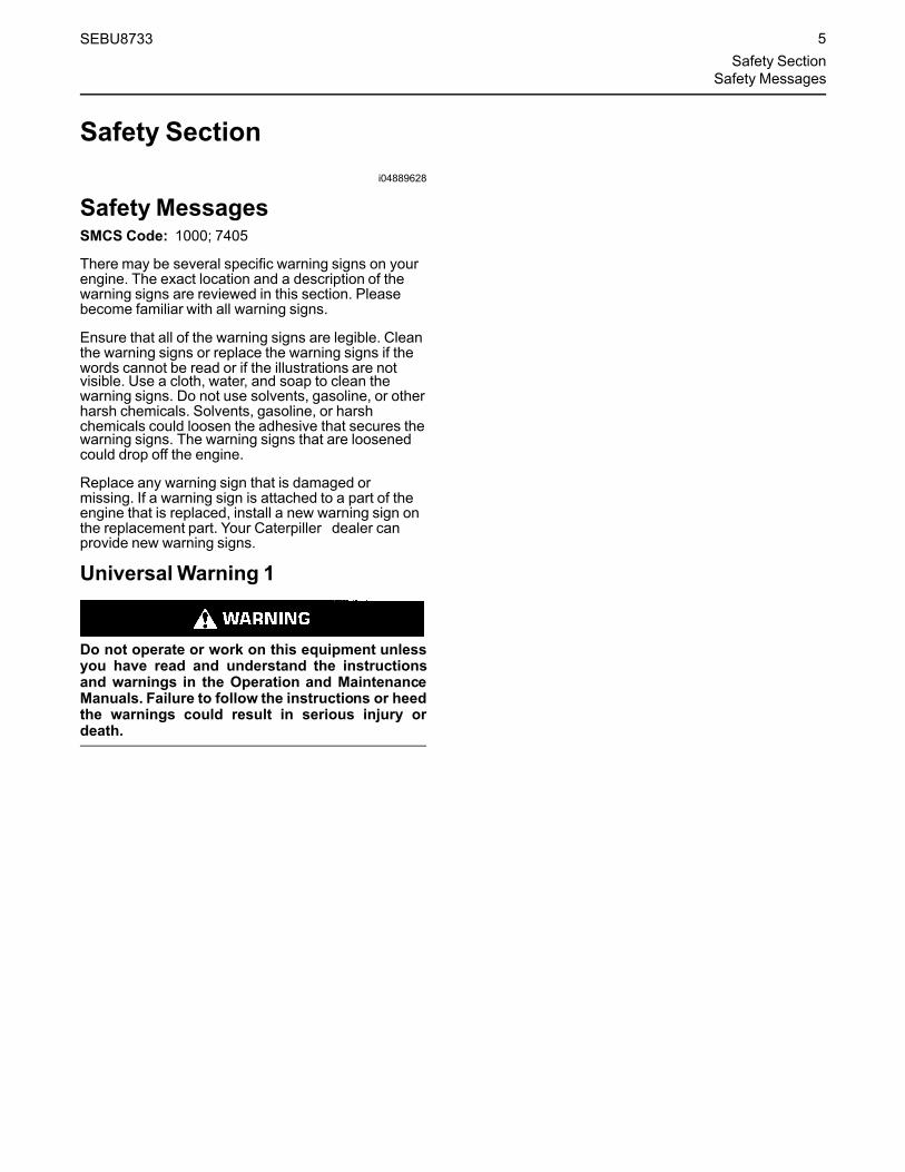
UniversalWarning 1
Do not operate or work on this equipment unlessyou have read and understand the instructionsand warnings in the Operation and MaintenanceManuals. Failure to follow the instructions or heedthe warnings could result in serious injury ordeath.
SEBU8733 5Safety Section
Safety Messages

Illustration 1 g03022899
Typical example
The universal warning label is install in two positionson the engine. On the valve mechanism cover and onthe intake manifold, refer to illustration 1 .
Ether Warning 2
Do not use aerosol types of starting aids such asether. Such use could result in an explosion andpersonal injury.
Illustration 2 g03023096
Typical example
6 SEBU8733Safety SectionSafety Messages

The ether warning label is installed on the intakemanifold, refer to illustration 2 .
Hand (High Pressure) 3
Contact with high pressure fuel may cause fluidpenetration and burn hazards. High pressure fuelspray may cause a fire hazard. Failure to followthese inspection, maintenance and service in-structionsmay cause personal injury or death.
Illustration 3 g03023097
Typical example
The hand high-pressure warning label is a rap aroundlabel installed on the main injection line, refer toillustration 3 .
SEBU8733 7Safety Section
Safety Messages

i05474090
General Hazard InformationSMCS Code: 1000; 4450; 7405
Illustration 4 g00104545
Attach a “Do Not Operate” warning tag or a similarwarning tag to the start switch or to the controlsbefore the engine is serviced or before the engine isrepaired. These warning tags (Special Instruction,SEHS7332) are available from your Cat dealer.Attach the warning tags to the engine and to eachoperator control station. When appropriate,disconnect the starting controls.
Do not allow unauthorized personnel on the engine,or around the engine when the engine is beingserviced.
• Tampering with the engine installation or tamperingwith the OEM supplied wiring can be dangerous.Personal injury, death and/or engine damagecould result.
• Vent the engine exhaust to the outside when theengine is operated in an enclosed area.
• If the engine is not running, do not release thesecondary brake or the parking brake systemsunless the vehicle is blocked or unless the vehicleis restrained.
• Wear a hard hat, protective glasses, and otherprotective equipment, as required.
• When work is performed around an engine that isoperating, wear protective devices for ears in orderto help prevent damage to hearing.
• Do not wear loose clothing or jewelry that can snagon controls or on other parts of the engine.
• Ensure that all protective guards and all covers aresecured in place on the engine.
• Never put maintenance fluids into glasscontainers. Glass containers can break.
• Use all cleaning solutions with care.
• Report all necessary repairs.
Unless other instructions are provided, perform themaintenance under the following conditions:
8 SEBU8733Safety SectionGeneral Hazard Information

• The engine is stopped. Ensure that the enginecannot be started.
• The protective locks or the controls are in theapplied position.
• Engage the secondary brakes or parking brakes.
• Block the vehicle or restrain the vehicle beforemaintenance or repairs are performed.
• Disconnect the batteries when maintenance isperformed or when the electrical system isserviced. Disconnect the battery ground leads.Tape the leads in order to help prevent sparks. Ifequipped, allow the diesel exhaust fluid to bepurged before disconnecting the battery.
• If equipped, disconnect the connectors for the unitinjectors that are located on the valve cover base.This action will help prevent personal injury fromthe high voltage to the unit injectors. Do not comein contact with the unit injector terminals while theengine is operating.
• Do not attempt any repairs or any adjustments tothe engine while the engine is operating.
• Do not attempt any repairs that are notunderstood. Use the proper tools. Replace anyequipment that is damaged or repair theequipment.
• For initial start-up of a new engine or for starting anengine that has been serviced, make provisions tostop the engine if an overspeed occurs. Thestopping of the engine may be accomplished byshutting off the fuel supply and/or the air supply tothe engine. Ensure that only the fuel supply line isshut off. Ensure that the fuel return line is open.
• Start the engine from the operators station (cab).Never short across the starting motor terminals orthe batteries. This action could bypass the engineneutral start system and/or the electrical systemcould be damaged.
Engine exhaust contains products of combustionwhich may be harmful to your health. Always start theengine and operate the engine in a well ventilatedarea. If the engine is in an enclosed area, vent theengine exhaust to the outside.
Cautiously remove the following parts. To helpprevent spraying or splashing of pressurized fluids,hold a rag over the part that is being removed.
• Filler caps
• Grease fittings
• Pressure taps
• Breathers
• Drain plugs
Use caution when cover plates are removed.Gradually loosen, but do not remove the last two boltsor nuts that are located at opposite ends of the coverplate or the device. Before removing the last two boltsor nuts, pry the cover loose in order to relieve anyspring pressure or other pressure.
Illustration 5 g00702020
• Wear a hard hat, protective glasses, and otherprotective equipment, as required.
• When work is performed around an engine that isoperating, wear protective devices for ears in orderto help prevent damage to hearing.
• Do not wear loose clothing or jewelry that can snagon controls or on other parts of the engine.
• Ensure that all protective guards and all covers aresecured in place on the engine.
• Never put maintenance fluids into glasscontainers. Glass containers can break.
• Use all cleaning solutions with care.
• Report all necessary repairs.
Unless other instructions are provided, performthe maintenance under the following conditions:
SEBU8733 9Safety Section
General Hazard Information

• The engine is stopped. Ensure that the enginecannot be started.
• Disconnect the batteries when maintenance isperformed or when the electrical system isserviced. Disconnect the battery ground leads.Tape the leads in order to help prevent sparks.
• Do not attempt any repairs that are notunderstood. Use the proper tools. Replace anyequipment that is damaged or repair theequipment.
Pressurized Air and WaterPressurized air and/or water can cause debris and/orhot water to be blown out. This action could result inpersonal injury.
When pressurized air and/or pressurized water isused for cleaning, wear protective clothing, protectiveshoes, and eye protection. Eye protection includesgoggles or a protective face shield.
The maximum air pressure for cleaning purposesmust be below 205 kPa (30 psi). The maximum waterpressure for cleaning purposes must be below275 kPa (40 psi).
Fluid PenetrationPressure can be trapped in the hydraulic circuit longafter the engine has been stopped. The pressure cancause hydraulic fluid or items such as pipe plugs toescape rapidly if the pressure is not relieved correctly.
Do not remove any hydraulic components or partsuntil pressure has been relieved or personal injurymay occur. Do not disassemble any hydrauliccomponents or parts until pressure has been relievedor personal injury may occur. Refer to the OEMinformation for any procedures that are required torelieve the hydraulic pressure.
Illustration 6 g00687600
Always use a board or cardboard when you check fora leak. Leaking fluid that is under pressure canpenetrate body tissue. Fluid penetration can causeserious injury and possible death. A pin hole leak cancause severe injury. If fluid is injected into your skin,you must get treatment immediately. Seek treatmentfrom a doctor that is familiar with this type of injury.
Containing Fluid SpillageCare must be taken to ensure that fluids arecontained during performance of inspection,maintenance, testing, adjusting, and repair of theproduct. Be prepared to collect the fluid with suitablecontainers before opening any compartment ordisassembling any component containing fluids.
Refer to Special Publication, NENG2500, “CatDealer Service Tool Catalog” for tools and suppliessuitable to collect and contain fluids on Cat products.
Dispose of all fluids according to local regulations andmandates.
10 SEBU8733Safety SectionGeneral Hazard Information

Inhalation
Illustration 7 g00702022
ExhaustUse caution. Exhaust fumes can be hazardous tohealth. If you operate the equipment in an enclosedarea, adequate ventilation is necessary.
Asbestos InformationCat equipment and replacement parts that areshipped from Caterpillar are asbestos free.Caterpillar recommends the use of only genuine Catreplacement parts. Use the following guidelines whenyou handle any replacement parts that containasbestos or when you handle asbestos debris.
Use caution. Avoid inhaling dust that might begenerated when you handle components that containasbestos fibers. Inhaling this dust can be hazardousto your health. The components that may containasbestos fibers are brake pads, brake bands, liningmaterial, clutch plates, and some gaskets. Theasbestos that is used in these components is usuallybound in a resin or sealed in some way. Normalhandling is not hazardous unless airborne dust thatcontains asbestos is generated.
If dust that may contain asbestos is present, there areseveral guidelines that should be followed:
• Never use compressed air for cleaning.
• Avoid brushing materials that contain asbestos.
• Avoid grinding materials that contain asbestos.
• Use a wet method in order to clean up asbestosmaterials.
• A vacuum cleaner that is equipped with a highefficiency particulate air filter (HEPA) can also beused.
• Use exhaust ventilation on permanent machiningjobs.
• Wear an approved respirator if there is no otherway to control the dust.
• Comply with applicable rules and regulations forthe work place. In the United States , useOccupational Safety and Health Administration(OSHA) requirements. These OSHArequirements can be found in 29 CFR 1910.1001.
• Obey environmental regulations for the disposal ofasbestos.
• Stay away from areas that might have asbestosparticles in the air.
Dispose of Waste Properly
Illustration 8 g00706404
Improperly disposing of waste can threaten theenvironment. Potentially harmful fluids should bedisposed of according to local regulations.
Always use leakproof containers when you drainfluids. Do not pour waste onto the ground, down adrain, or into any source of water.
SEBU8733 11Safety Section
General Hazard Information

i04891356
Burn PreventionSMCS Code: 1000; 4450; 7405
Do not touch any part of an operating engine system.The engine, the exhaust, and the engineaftertreatment system can reach temperatures ashigh as 650° C (1202° F) under normal operatingconditions.
Allow the engine system to cool before anymaintenance is performed. Relieve all pressure in theair system, hydraulic system, lubrication system, fuelsystem, and the cooling system before the relateditems are disconnected.
Contact with high pressure fuel may cause fluidpenetration and burn hazards. High pressure fuelspray may cause a fire hazard. Failure to followthese inspection, maintenance and service in-structionsmay cause personal injury or death.
After the engine has stopped, you must wait for 10minutes in order to allow the fuel pressure to bepurged from the high-pressure fuel lines before anyservice or repair is performed on the engine fuel lines.
Allow the pressure to be purged in the air system, inthe hydraulic system, in the lubrication system, or inthe cooling system before any lines, fittings, or relateditems are disconnected.
Induction System
Sulfuric Acid Burn Hazard may cause serious per-sonal injury or death.
The exhaust gas cooler may contain a smallamount of sulfuric acid. The use of fuel with sulfurlevels greater than 15 ppm may increase theamount of sulfuric acid formed. The sulfuric acidmay spill from the cooler during service of the en-gine. The sulfuric acid will burn the eyes, skin andclothing on contact. Always wear the appropriatepersonal protective equipment (PPE) that is notedon a material safety data sheet (MSDS) for sulfuricacid. Always follow the directions for first aid thatare noted on a material safety data sheet (MSDS)for sulfuric acid.
CoolantWhen the engine is at operating temperature, theengine coolant is hot. The coolant is also underpressure. The radiator and all lines to the heaters,aftertreatment system or to the engine contain hotcoolant.
Any contact with hot coolant or with steam can causesevere burns. Allow cooling system components tocool before the cooling system is drained.
Check that the coolant level after the engine hasstopped and the engine has been allowed to cool.
Ensure that the filler cap is cool before removing thefiller cap. The filler cap must be cool enough to touchwith a bare hand. Remove the filler cap slowly inorder to relieve pressure.
Cooling system conditioner contains alkali. Alkali cancause personal injury. Do not allow alkali to contactthe skin, the eyes, or the mouth.
OilsHot oil and hot lubricating components can causepersonal injury. Do not allow hot oil to contact theskin. Also, do not allow hot components to contact theskin.
BatteriesElectrolyte is an acid. Electrolyte can cause personalinjury. Do not allow electrolyte to contact the skin orthe eyes. Always wear protective glasses forservicing batteries. Wash hands after touching thebatteries and connectors. Use of gloves isrecommended.
AftertreatmentSystemAllow the aftertreatment to cool down before anymaintenance or repair is performed.
12 SEBU8733Safety SectionBurn Prevention

i05408756
Fire Prevention and ExplosionPreventionSMCS Code: 1000; 4450; 7405
Illustration 9 g00704000
All fuels, most lubricants, and some coolant mixturesare flammable.
Flammable fluids that are leaking or spilled onto hotsurfaces or onto electrical components can cause afire. Fire may cause personal injury and propertydamage.
A flash fire may result if the covers for the enginecrankcase are removed within 15 minutes after anemergency shutdown.
Determine whether the engine will be operated in anenvironment that allows combustible gases to bedrawn into the air inlet system. These gases couldcause the engine to overspeed. Personal injury,property damage, or engine damage could result.
If the application involves the presence ofcombustible gases, consult your Caterpillar dealer foradditional information about suitable protectiondevices.
Remove all flammable materials such as fuel, oil, anddebris from the engine. Do not allow any flammablematerials to accumulate on the engine.
Store fuels and lubricants in properly markedcontainers away from unauthorized persons. Storeoily rags and any flammable materials in protectivecontainers. Do not smoke in areas that are used forstoring flammable materials.
Do not expose the engine to any flame.
Exhaust shields (if equipped) protect hot exhaustcomponents from oil or fuel spray in a case of a line, atube, or a seal failure. Exhaust shields must beinstalled correctly.
Do not weld on lines or tanks that contain flammablefluids. Do not flame cut lines or tanks that containflammable fluid. Clean any such lines or tanksthoroughly with a nonflammable solvent prior towelding or flame cutting.
Wiring must be kept in good condition. All electricalwires must be properly routed and securely attached.Check all electrical wires daily. Repair any wires thatare loose or frayed before you operate the engine.Clean all electrical connections and tighten allelectrical connections.
Eliminate all wiring that is unattached or unnecessary.Do not use any wires or cables that are smaller thanthe recommended gauge. Do not bypass any fusesand/or circuit breakers.
Arcing or sparking could cause a fire. Secureconnections, recommended wiring, and properlymaintained battery cables will help to prevent arcingor sparking.
Contact with high pressure fuel may cause fluidpenetration and burn hazards. High pressure fuelspray may cause a fire hazard. Failure to followthese inspection, maintenance and service in-structionsmay cause personal injury or death.
After the engine has stopped, you must wait for 10minutes in order to allow the fuel pressure to bepurged from the high-pressure fuel lines before anyservice or repair is performed on the engine fuel lines.
Inspect all lines and hoses for wear or fordeterioration. The hoses must be properly routed.The lines and hoses must have adequate supportand secure clamps. Tighten all connections to therecommended torque. Leaks can cause fires.
Oil filters and fuel filters must be properly installed.The filter housings must be tightened to the propertorque.
SEBU8733 13Safety Section
Fire Prevention and Explosion Prevention

Illustration 10 g00704059
Use caution when you are refueling an engine. Do notsmoke while you are refueling an engine. Do notrefuel an engine near open flames or sparks. Alwaysstop the engine before refueling.
Avoid static electricity risk when fueling. Ultra lowsulfur diesel (ULSD) poses a greater static ignitionhazard that earlier diesel formulation with a highersulfur content. Avoid death or serious injury from thefire or explosion. Consult with your fuel or fuel systemsupplier to ensure that the delivery system is incompliance with fueling standards for propergrounding and bonding practices.
Illustration 11 g00704135
Gases from a battery can explode. Keep any openflames or sparks away from the top of a battery. Donot smoke in battery charging areas.
Never check the battery charge by placing a metalobject across the terminal posts. Use a voltmeter or ahydrometer.
Improper jumper cable connections can cause anexplosion that can result in injury. Refer to theOperation Section of this manual for specificinstructions.
Do not charge a frozen battery. A frozen battery maycause an explosion.
The batteries must be kept clean. The covers (ifequipped) must be kept on the cells. Use therecommended cables, connections, and battery boxcovers when the engine is operated.
Fire ExtinguisherMake sure that a fire extinguisher is available. Befamiliar with the operation of the fire extinguisher.Inspect the fire extinguisher and service the fireextinguisher regularly. Obey the recommendations onthe instruction plate.
EtherEther is flammable and poisonous.
Do not smoke while you are replacing an ethercylinder or while you are using an ether spray.
Do not store ether cylinders in living areas or in theengine compartment. Do not store ether cylinders indirect sunlight or in temperatures above 49 °C(120 °F). Keep ether cylinders away from openflames or sparks.
14 SEBU8733Safety SectionFire Prevention and Explosion Prevention

Dispose of used ether cylinders properly. Do notpuncture an ether cylinder. Keep ether cylinders awayfrom unauthorized personnel.
Lines, Tubes, and HosesDo not bend high-pressure lines. Do not strike high-pressure lines. Do not install any lines that are bent ordamaged.
Repair any lines that are loose or damaged. Leakscan cause fires. Consult your Caterpillar dealer forrepair or for replacement parts.
Check lines, tubes, and hoses carefully. Do not useyour bare hand to check for leaks. Use a board orcardboard to check for leaks. Tighten all connectionsto the recommended torque.
Replace the parts if any of the following conditionsare present:
• High-pressure fuel line or lines are removed.
• End fittings are damaged or leaking.
• Outer coverings are chafed or cut.
• Wires are exposed.
• Outer coverings are ballooning.
• Flexible part of the hose is kinked.
• Outer covers have embedded armoring.
• End fittings are displaced.
Make sure that all clamps, guards, and heat shieldsare installed correctly. During engine operation, thiswill help to prevent vibration, rubbing against otherparts, and excessive heat.
i01359666
Crushing Prevention andCutting PreventionSMCS Code: 1000; 4450; 7405
Support the component properly when work beneaththe component is performed.
Unless other maintenance instructions are provided,never attempt adjustments while the engine isrunning.
Stay clear of all rotating parts and of all moving parts.Leave the guards in place until maintenance isperformed. After the maintenance is performed,reinstall the guards.
Keep objects away from moving fan blades. The fanblades will throw objects or cut objects.
When objects are struck, wear protective glasses inorder to avoid injury to the eyes.
Chips or other debris may fly off objects when objectsare struck. Before objects are struck, ensure that noone will be injured by flying debris.
i04016709
Mounting and DismountingSMCS Code: 1000; 4450; 7405
Do not climb on the engine or the engineaftertreatment. The engine and aftertreatment havenot been designed with mounting or dismountinglocations.
Refer to the OEM for the location of foot and handholds for your specific application.
i03550790
High Pressure Fuel LinesSMCS Code: 1274
Contact with high pressure fuel may cause fluidpenetration and burn hazards. High pressure fuelspray may cause a fire hazard. Failure to followthese inspection, maintenance and service in-structionsmay cause personal injury or death.
SEBU8733 15Safety Section
Crushing Prevention and Cutting Prevention

Illustration 12 g01877473
(1) High pressure line(2) High pressure line(3) High pressure line
(4) High pressure line(5) High pressure line(6) High pressure line
(7) High pressure fuel manifold (rail)(8) High pressure line(9) Fuel transfer line that is high pressure
The high pressure fuel lines are the fuel lines that arebetween the high pressure fuel pump and the highpressure fuel manifold and the fuel lines that arebetween the fuel manifold and cylinder head. Thesefuel lines are different from fuel lines on other fuelsystems.
This is because of the following items:
• The high pressure fuel lines are constantlycharged with high pressure.
• The internal pressures of the high pressure fuellines are higher than other types of fuel system.
• The high pressure fuel lines are formed to shapeand then strengthened by a special process.
Do not step on the high pressure fuel lines. Do notdeflect the high pressure fuel lines. Do not bend orstrike the high pressure fuel lines. Deformation ordamage of the high pressure fuel lines may cause apoint of weakness and potential failure.
Do not check the high pressure fuel lines with theengine or the starting motor in operation. After theengine has stopped, you must wait for 10 minutes inorder to allow the fuel pressure to be purged from thehigh pressure fuel lines before any service or repair isperformed on the engine fuel lines.
Do not loosen the high pressure fuel lines in order toremove air from the fuel system. This procedure is notrequired.
Visually inspect the high pressure fuel lines beforethe engine is started. This inspection should be eachday.
If you inspect the engine in operation, always use theproper inspection procedure in order to avoid a fluidpenetration hazard. Refer to Operation andMaintenance Manual, “General hazard Information”.
• Inspect the high pressure fuel lines for damage,deformation, a nick, a cut, a crease, or a dent.
• Do not operate the engine with a fuel leak. If thereis a leak do not tighten the connection in order tostop the leak. The connection must only betightened to the recommended torque. Refer toDisassembly and Assembly, “Fuel injection lines -Remove and Fuel injection lines - Install”.
• If the high pressure fuel lines are torqued correctlyand the high pressure fuel lines are leaking thehigh pressure fuel lines must be replaced.
• Ensure that all clips on the high pressure fuel linesare in place. Do not operate the engine with clipsthat are damaged, missing or loose.
• Do not attach any other item to the high pressurefuel lines.
• Loosened high pressure fuel lines must bereplaced. Also removed high pressure fuel linesmust be replaced. Refer to Disassembly andassembly manual, “Fuel Injection Lines - Install”.
16 SEBU8733Safety SectionHigh Pressure Fuel Lines

i03560601
Before Starting EngineSMCS Code: 1000
NOTICEFor initial start-up of a new or rebuilt engine, and forstart-up of an engine that has been serviced, makeprovision to shut the engine off should an overspeedoccur. This may be accomplished by shutting off theair and/or fuel supply to the engine.
Engine exhaust contains products of combustionwhich may be harmful to your health. Always startand operate the engine in a well ventilated areaand, if in an enclosed area, vent the exhaust to theoutside.
Inspect the engine for potential hazards.
Do not start the engine or move any of the controls ifthere is a “DO NOT OPERATE” warning tag orsimilar warning tag attached to the start switch or tothe controls.
Before starting the engine, ensure that no one is on,underneath, or close to the engine. Ensure that thearea is free of personnel.
If equipped, ensure that the lighting system for theengine is suitable for the conditions. Ensure that alllights work properly, if equipped.
All protective guards and all protective covers mustbe installed if the engine must be started in order toperform service procedures. To help prevent anaccident that is caused by parts in rotation, workaround the parts carefully.
Do not bypass the automatic shutoff circuits. Do notdisable the automatic shutoff circuits. The circuits areprovided in order to help prevent personal injury. Thecircuits are also provided in order to help preventengine damage.
See the Service Manual for repairs and foradjustments.
i03635086
Engine StartingSMCS Code: 1000
Do not use aerosol types of starting aids such asether. Such use could result in an explosion andpersonal injury.
If a warning tag is attached to the engine start switchor to the controls DO NOTstart the engine or movethe controls. Consult with the person that attachedthe warning tag before the engine is started.
All protective guards and all protective covers mustbe installed if the engine must be started in order toperform service procedures. To help prevent anaccident that is caused by parts in rotation, workaround the parts carefully.
Start the engine from the operator's compartment orfrom the engine start switch.
Always start the engine according to the procedurethat is described in the Operation and MaintenanceManual, “Engine Starting” topic in the OperationSection. Knowing the correct procedure will help toprevent major damage to the engine components.Knowing the procedure will also help to preventpersonal injury.
To ensure that the jacket water heater (if equipped)and/or the lube oil heater (if equipped) is workingcorrectly, check the water temperature gauge and/orthe oil temperature gauge during the heateroperation.
Engine exhaust contains products of combustionwhich can be harmful to your health. Always start theengine and operate the engine in a well ventilatedarea. If the engine is started in an enclosed area, ventthe engine exhaust to the outside.
These engines are equipped with a glow plug startingaid in each individual cylinder that heats the intake airin order to improve starting. Some Caterpillarengines may have a cold starting system that iscontrolled by the ECM that allows a controlled flow ofether into the engine. The ECM will disconnect theglow plugs before the ether is introduced. Thissystem would be installed at the factory.
SEBU8733 17Safety Section
Before Starting Engine

i03648639
Engine StoppingSMCS Code: 1000
To avoid overheating of the engine and acceleratedwear of the engine components, stop the engineaccording to this Operation and Maintenance Manual,“Engine Stopping” topic (Operation Section).
Use the Emergency Stop Button (if equipped) ONLYin an emergency situation. DO NOT use theEmergency Stop Button for normal engine stopping.After an emergency stop, DO NOTstart the engineuntil the problem that caused the emergency stop hasbeen corrected.
On the initial start-up of a new engine or an enginethat has been serviced, make provisions to stop theengine if an overspeed condition occurs.
i04891806
Electrical SystemSMCS Code: 1000; 1400
Never disconnect any charging unit circuit or batterycircuit cable from the battery when the charging unit isoperating. A spark can cause the combustible gasesthat are produced by some batteries to ignite.
To help prevent sparks from igniting combustiblegases that are produced by some batteries, thenegative “−” cable should be connected last from theexternal power source to the primary position forgrounding.
Check the electrical wires daily for wires that areloose or frayed. Tighten all loose electricalconnections before the engine is started. Repair allfrayed electrical wires before the engine is started.See the Operation and Maintenance Manual forspecific starting instructions.
Grounding Practices
Illustration 13 g01888534
Typical example(1) Ground to battery(2) Ground to starting motor(3) Starting motor to engine block
18 SEBU8733Safety SectionEngine Stopping

Illustration 14 g03027396
Typical example(5) Ground to the battery(6) Ground to the engine block(7) Primary position for grounding
Correct grounding for the engine electrical system isnecessary for optimum engine performance andreliability. Incorrect grounding will result inuncontrolled electrical circuit paths and in unreliableelectrical circuit paths.
Uncontrolled electrical circuit paths can result indamage to the crankshaft bearing journal surfacesand to aluminum components.
Engines that are installed without engine-to-frameground straps can be damaged by electricaldischarge.
To ensure that the engine and the engine electricalsystems function correctly, an engine-to-frameground strap with a direct path to the battery must beused. This path may be provided by way of a directengine ground to the frame.
The connections for the grounds should be tight andfree of corrosion. The engine alternator must begrounded to the negative “-” battery terminal. Thewire used must be adequate to handle the fullcharging current of the alternator.
The power supply connections and the groundconnections for the engine electronics should alwaysbe from the isolator to the battery.
i05206178
Engine ElectronicsSMCS Code: 1000; 1900
Tampering with the electronic system installationor the OEM wiring installation can be dangerousand could result in personal injury or death and/orengine damage.
Electrical Shock Hazard. The electronic unit injec-tors use DC voltage. The ECM sends this voltageto the electronic unit injectors. Do not come incontact with the harness connector for the elec-tronic unit injectors while the engine is operating.Failure to follow this instruction could result inpersonal injury or death.
This engine has a comprehensive, programmableEngine Monitoring System. The Electronic ControlModule (ECM) has the ability to monitor the engineoperating conditions. If any of the engine parametersextend outside an allowable range, the ECM willinitiate an immediate action.
The following actions are available for enginemonitoring control:
• Warning
• Derate
• Shutdown
The following monitored engine operating conditionsand components can limit engine speed and/or theengine power:
• Engine Coolant Temperature
• Engine Oil Pressure
• Engine Speed
• Intake Manifold Air Temperature
• Wastegate Regulator
• Supply Voltage to Sensors
• Fuel Temperature
• Fuel Pressure in Manifold (Rail)
• NOxReduction System
• Engine Aftertreatment System
SEBU8733 19Safety Section
Engine Electronics
The Engine Monitoring package can vary for differentengine models and different engine applications.However, the monitoring system and the enginemonitoring control will be similar for all engines.
Note:Many of the engine control systems anddisplay modules that are available for CaterpillarEngines will work in unison with the EngineMonitoring System. Together, the two controls willprovide the engine monitoring function for the specificengine application. Refer to Troubleshooting for moreinformation on the Engine Monitoring System.
20 SEBU8733Safety SectionEngine Electronics

Product InformationSection
General Informationi05347319
Model View IllustrationsSMCS Code: 1000
The following model views show typical features ofthe engine. Due to individual applications, yourengine may appear different from the illustrations.Single Turbocharged Engine with Installed Aftertreatment
Illustration 15 g03393436
Typical example
SEBU8733 21Product Information Section
Model View Illustrations

Engine Views with Series Turbochargers
Illustration 16 g03387645
Typical example(1) Rear engine lifting eye(2) High-pressure turbocharger(3) Front engine lifting eye
(4) Alternator(5) Low-pressure turbocharger(6) Oil drain plug
(7) Back pressure valve
22 SEBU8733General InformationModel View Illustrations

Illustration 17 g03387666
Typical example(8) Secondary fuel filter(9) Primary fuel filter(10) Crankcase breather(11) Engine Electronic Control Module
(ECM)
(12) Flywheel housing(13) Flywheel(14) Solenoid for starting motor(15) Startingmotor(16) Oil filter
(17) Oil level gauge (Dipstick)(18) Oil drain tap(19) location for the oil sampling valve(20) High-pressure fuel pump
SEBU8733 23General Information
Model View Illustrations

Illustration 18 g03387667
Typical example(21) NOx Reduction system (NRS)(22) Air intake(23) Coolant outlet
(24) Oil filler cap(25) Water pump(26) Coolant intake
(27) Crankshaft damper(28) Belt tensioner(29) Belt
24 SEBU8733General InformationModel View Illustrations

Off Engine Components
Illustration 19 g03387619
Items that can be supplied loose.(1) Clean emission module(2) Pump electronics tank unit(3) Heated line(4) Soot sensor control
(5) NOx sensors(6) In-line fuel filter(7) Priming/tranfer fuel pump(8) Primary fuel filter
(9) Flexible exhaust pipe assembly(9 A) Protection sleeve for flexible exhaust
pipe(10) Inlet air temperature sensor
Note:Use the sleeve (9 A) for transportation only.
SEBU8733 25General Information
Model View Illustrations

Engine AftertreatmentSystem
Illustration 20 g03027726
Typical example(1) Clean Emission Module (CEM)(2) Lifting eyes for CEM
(3) Exhaust intake connection(4) Exhaust outlet connection
(5) Diesel Exhaust Fluid (DEF) injector
26 SEBU8733General InformationModel View Illustrations

Illustration 21 g03034176
Typical example(1) Pump Electronics Tank Unit (PETU)(2) Diesel Exhaust Fluid (DEF) tank filler cap(3) Coolant inlet
(4) Coolant outlet(5) Dosing Control Module (DCU)(6) DEF Tank
(7) Heated DEF line(8) Harness connections(9) DEF drain plug
The size of the DEF tank will depend on theapplication. For more information on theaftertreatment system, refer to this Operation andMaintenance Manual, “Sensors and ElectricalComponents”.
i05352909
Product Description(Engine and Aftertreatment)SMCS Code: 1000; 4450; 4491
There are two variants of the C7.1 industrial enginethe single turbocharged engine and the seriesturbocharged engine.
The Caterpillar C7.1 Industrial Engine has thefollowing characteristics.
• In-line Six cylinder
• Four stroke cycle
• Four valves in each cylinder
• Series turbocharged charge cooled/or Singleturbocharged charge cooled
• Aftertreatment System
The Clean Emissions Module (CEM) is constructed ofthree main items, the diesel oxidation catalyst, thediesel particulate filter, and the Selective CatalyticReduction (SCR). The SCR requires the use of DieselExhaust Fluid (DEF) to be injected into the system inorder to lower the emissions from the engine. The(DEF) is stored and controlled by the pump electronictank unit. The DEF tank can be installed separatefrom the electronic pump unit.
SEBU8733 27General InformationProduct Description

Engine SpecificationsNote: The front end of the engine is opposite theflywheel end of the engine. The left and the rightsides of the engine are determined from the flywheelend. The number 1 cylinder is the front cylinder.
Illustration 22 g01127295
Cylinder and valve location(A) Exhaust valves(B) Inlet valves
Table 1
C7.1 Single TurbochargedEngine Specifications
Operating Range (rpm) 800 to 2500(1)
Number of Cylinders 6 In-Line
Bore 105 mm (4.13 inch)
Stroke 127 mm (5 inch)
Power 116 to 151 kW(155.5 to 202.5 hp)
Aspiration Turbocharged charge cooled
Compression Ratio 16.4:1
Displacement 7.01 L (428 in3)
Firing Order 1-5-3-6-2-4
Rotation (flywheel end) Counterclockwise(1) The operating rpm is dependent on the engine rating, the appli-
cation, and the configuration of the throttle.
Table 2
C7.1 Series Turbocharged Engine Specifications
Operating Range (rpm) 800 to 2500(1)
Number of Cylinders 6 In-Line
Bore 105 mm (4.13 inch)
Stroke 135 mm (5.31495 inch)
(continued)
(Table 2, contd)
Power 151 to 205 kW(202.5 to 274.9 hp)
Aspiration Turbocharged charge cooled
Compression Ratio 16.4:1
Displacement 7.01 L (428 in3)
Firing Order 1-5-3-6-2-4
Rotation (flywheel end) Counterclockwise(1) The operating rpm is dependent on the engine rating, the appli-
cation, and the configuration of the throttle.
Electronic Engine FeaturesThe engine and aftertreatment operating conditionsare monitored. The Electronic Control Module (ECM)controls the response of the engine to theseconditions and to the demands of the operator. Theseconditions and operator demands determine theprecise control of fuel injection by the ECM. Theelectronic engine control system provides thefollowing features:
• Engine monitoring
• Engine speed governing
• Control of the injection pressure
• Cold start strategy
• Automatic air/fuel ratio control
• Torque rise shaping
• Injection timing control
• System diagnostics
• NOx reduction system control
• Aftertreatment system control
The ECM provides an electronic governor thatcontrols the injector output in order to maintain thedesired engine rpm.
For more information on electronic engine features,refer to the Operation and Maintenance Manual,“Features and Controls” topic (Operation Section).
Engine DiagnosticsThe engine has built-in diagnostics in order to ensurethat the engine systems are functioning correctly. Theoperator will be alerted to the condition by a “Stop orWarning” lamp. Under certain conditions, the enginehorsepower and the vehicle speed may be limited.The electronic service tool may be used to display thediagnostic codes.
28 SEBU8733General InformationProduct Description

There are three types of diagnostic codes: active,logged and event.
Most of the diagnostic codes are logged and stored inthe ECM. For additional information, refer to theOperation and Maintenance Manual, “EngineDiagnostics” topic (Operation Section).
Engine Cooling and LubricationThe cooling system and lubrication system consistsof the following components:
• Gear-driven centrifugal water pump
• Water temperature regulator which regulates theengine coolant temperature
• Gear-driven gerotor type oil pump
• Oil cooler
The engine lubricating oil is supplied by a gerotortype oil pump. The engine lubricating oil is cooled andthe engine lubricating oil is filtered. The bypass valvecan provide unrestricted flow of lubrication oil to theengine if the oil filter element should becomeplugged.
Engine efficiency, efficiency of emission controls, andengine performance depend on adherence to properoperation and maintenance recommendations.Engine performance and efficiency also depend onthe use of recommended fuels, lubrication oils, andcoolants. Refer to this Operation and MaintenanceManual, “Maintenance Interval Schedule” for moreinformation on maintenance items.
Engine Service LifeEngine efficiency and maximum utilization of engineperformance depend on the adherence to properoperation and maintenance recommendations. Inaddition, use recommended fuels, coolants, andlubricants. Use the Operation and MaintenanceManual as a guide for required engine maintenance.
Expected engine life is generally predicted by theaverage power that is demanded. The average powerthat is demanded is based on fuel consumption of theengine over time. Reduced hours of operation at fullthrottle and/or operating at reduced throttle settingsresult in a lower average power demand. Reducedhours of operation will increase the length ofoperating time before an engine overhaul is required.For more information, refer to the Operation andMaintenance Manual, “Overhaul Considerations”topic (Maintenance Section).
Aftermarket Products andCaterpillar EnginesCaterpillar does not warrant the quality orperformance of non-Caterpillar fluids and filters.
When auxiliary devices, accessories, or consumables(filters, additives, catalysts,) which are made by othermanufacturers are used on Caterpillar products, theCaterpillar warranty is not affected simply becauseof such use.
However, failures that result from the installationor use of other manufacturers devices,accessories, or consumables are NOT Caterpillardefects. Therefore, the defects are NOTcoveredunder the Caterpillar warranty.
AftertreatmentSystemThe aftertreatment system is approved for use byCaterpillar . In order to be emission-compliant onlythe approved Caterpillar aftertreatment system mustbe used on a Caterpillar engine.
SEBU8733 29General InformationProduct Description

Product IdentificationInformation
i04897160
Plate Locations and FilmLocationsSMCS Code: 1000; 4450
Illustration 23 g03046077
(1) Location of the engine serial number plate
Serial Number PlateThe engine serial number plate (1) is located on theleft side of the cylinder block to the rear of the frontengine mounting.
Caterpiller dealers need all of these numbers in orderto determine the components that were included withthe engine. The full serial number permits accurateidentification of replacement part numbers.
Illustration 24 g03047463
Typical example
i05349518
Plate Locations and FilmLocations(AftertreatmentSystem)SMCS Code: 1000; 4450
Clean EmissionModule (CEM)
Illustration 25 g03047499
Typical example
The identification plate (1) is located on the intakeend of the CEM.
30 SEBU8733Product Identification InformationPlate Locations and Film Locations

Illustration 26 g03388367
Typical example CEM identification plate
Pump Electronic Tank Unit (PETU)
Illustration 27 g03419905
Typical example
The location of the PETU serial plate (2).
Illustration 28 g03418749
Typical example PETU serial plate
Record all the information on the CEM and PETUserial plates. The information will be required by yourCat dealer in order to identify replacement partnumbers.
i04274710
Emissions CertificationFilmSMCS Code: 1000; 7405
The label for the emission is installed on the frontgear cover.
Note: A second emission label will be supplied withthe engine. If necessary, the second emission labelwill be installed on the application by the originalequipment manufacturer.
SEBU8733 31Product Identification Information
Emissions Certification Film

Illustration 29 g02443539
Typical example
i05362542
Reference InformationSMCS Code: 1000; 4450
Information for the following items may be needed toorder parts. Locate the information for your engine.Record the information in the appropriate space.Make a copy of this list for a record. Keep theinformation for future reference.
Record for ReferenceEngine Model
Engine Serial number
Engine Low Idle rpm
Engine Full Load rpm
In Line Fuel Filter
Primary Fuel Filter
Secondary Fuel Filter Element
Lubrication Oil Filter Element
Auxiliary Oil Filter Element
Total Lubrication System Capacity
Total Cooling System Capacity
Air Cleaner Element
Drive Belt
Clean Emission ModulePart Number
Serial Number
Pump Electronics Tank Unit
Part Number
Serial Number
32 SEBU8733Product Identification InformationReference Information

Operation Section
Lifting and Storagei05350494
Product LiftingSMCS Code: 7000; 7002
NOTICENever bend the eyebolts and the brackets. Only loadthe eyebolts and the brackets under tension. Remem-ber that the capacity of an eyebolt is less as the anglebetween the supporting members and the object be-comes less than 90 degrees.
When it is necessary to remove a component at anangle, only use a link bracket that is properly rated forthe weight.
Read all the information within produce lifting beforeany lifting is attempted. Ensure that the correct set oflifting eyes for the assembly to be lifted have beenselected.
Use a hoist to remove heavy components. Use anadjustable lifting beam to lift the assembly. Allsupporting members (chains and cables) should beparallel to each other. The chains and cables shouldbe perpendicular to the top of the object that is beinglifted.
Engine and Clean EmissionModule(CEM)
Illustration 30 g03051657
Typical example(1) Lifting eyes for engine and aftertreatment.
Refer to illustration 30 for the location of the liftingeyes in order to lift the assembly.
CEM Only
Ensure that the exhaust inlet for the CEM is notdamaged during removal and installation. Do notallow the weigh of the CEM to act on the exhaustinlet.
SEBU8733 33Operation Section
Product Lifting
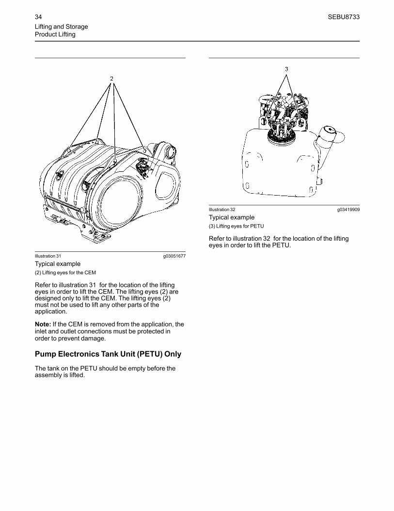
Illustration 31 g03051677
Typical example(2) Lifting eyes for the CEM
Refer to illustration 31 for the location of the liftingeyes in order to lift the CEM. The lifting eyes (2) aredesigned only to lift the CEM. The lifting eyes (2)must not be used to lift any other parts of theapplication.
Note: If the CEM is removed from the application, theinlet and outlet connections must be protected inorder to prevent damage.
Pump Electronics Tank Unit (PETU) Only
The tank on the PETU should be empty before theassembly is lifted.
Illustration 32 g03419909
Typical example(3) Lifting eyes for PETU
Refer to illustration 32 for the location of the liftingeyes in order to lift the PETU.
34 SEBU8733Lifting and StorageProduct Lifting

Engine Only
Illustration 33 g03051679
Typical example(4) Lifting eyes for the engine
Refer to illustration 32 for the location of the liftingeyes in order to lift the engine.
i05359242
Product StorageSMCS Code: 7002
If the engine will not be started for several weeks, thelubricating oil will drain from the cylinder walls andfrom the piston rings. Rust can form on the cylinderliner surface. Rust on the cylinder liner surface willcause increased engine wear and a reduction inengine service life.
To help prevent excessive engine wear, use thefollowing guidelines:
• Complete all of the lubrication recommendationsthat are listed in this Operation and MaintenanceManual, “Maintenance Interval Schedule”(Maintenance Section).
• If freezing temperatures are expected, check thecooling system for adequate protection againstfreezing. See this Operation and MaintenanceManual, “Refill Capacities and Recommendations”(Maintenance Section).
If an engine is out of operation and if use of theengine is not planned, special precautions should bemade. If the engine will be stored for more than 1month, a complete protection procedure isrecommended.
Ensure that the outlets on the Clean Emission Module(CEM) are capped Ensure that the Diesel ExhaustFluid (DEF) injector connections are capped.
In order to prevent damage to the exhaust outletconnection during storage, the weight of the CEMmust not act on the exhaust outlet.
For more detailed information on engine storage, seeSpecial Instruction, SEHS9031, “Storage ProcedureFor Caterpillar Products”.
Your Cat dealer can assist in preparing the engine forextended storage periods.
AftertreatmentThe engine must be allowed to perform a DEF purgebefore the battery disconnect switch is turned off.Some applications, the engine can be equipped withdelayed engine shutdown. Allow 2 minutes after theengine has stopped before disconnecting the batterydisconnect switch.
The exhaust outlet of the aftertreatment must becapped. In order to prevent damage to the exhaustoutlet connection during storage, the weight of theCEM must not act on the exhaust outlet.
DEF Tank Storage
1. Ensure normal engine shutdown, allow the DEF tobe purged. Do not disconnect the batterydisconnect switch, allow 2 minutes after key offbefore disconnection.
2. Fill the tank with DEF that meet all the requirementdefined in ISO 22241-1.
3. Ensure that all DEF lines and electrical connectionare connected prior to prevent crystal fromforming.
4. Ensure that the DEF filler cap is correctly installed.
SEBU8733 35Lifting and StorageProduct Storage

Removal from Storage
DEF has a limited life, refer to table 3 for the time andtemperature range. DEF that is outside this rangeMUST be replaced.
On removal from storage the DEF quality in the tankmust be tested with a refractometer. The DEF in thetank must meet the requirements defined in ISO22241-1 and comply with table 3 .
1. If necessary, drain the tank and fill with DEF thatmeet ISO 22241-1.
2. Replace the DEF filter, refer to this Operation andMaintenance Manual, “Diesel Exhaust Fluid Filter-Clean/Replace”.
3. Ensure that the drive belt is correctly installed.Ensure that all engine coolant and engine oil hasthe correct specification and grade. Ensure that thecoolant and the engine oil are at the correct level.Start the engine. If a fault becomes active turn offthe engine, allow 2 minutes for the DEF system topurge, then restart the engine.
4. If the fault continues to stay active, refer toTroubleshooting for more information.
Table 3
Temperature Duration
10° C (50° F) 36 months
25° C (77° F) 18 months
30° C (86° F) 12 months
35° C (95° F)(1) 6 months
(1) At 35° C, significant degradation can occur. Check every batchbefore use.
36 SEBU8733Lifting and StorageProduct Storage

Features and Controlsi05416516
Alarms and ShutoffsSMCS Code: 7400
ShutoffsThe shutoffs are electrically operated or mechanicallyoperated. The electrically operated shutoffs arecontrolled by the ECM.
Shutoffs are set at critical levels for the followingitems:
• Operating temperature
• Operating pressure
• Operating level
• Operating rpm
The particular shutoff may need to be reset before theengine will start.
NOTICEAlways determine the cause of the engine shutdown.Make necessary repairs before attempting to restartthe engine.
Be familiar with the following items:
• Types and locations of shutoff
• Conditions which cause each shutoff to function
• The resetting procedure that is required to restartthe engine
AlarmsThe alarms are electrically operated. The operationsof the alarms are controlled by the ECM.
The alarm is operated by a sensor or by a switch.When the sensor or the switch is activated, a signal issent to the ECM. An event code is created by theECM. The ECM will send a signal in order toilluminate the lamp.
Your engine may be equipped with the followingsensors or switches:
Coolant temperature – The coolant temperaturesensor indicates high jacket water coolanttemperature.
Intake manifold air temperature – The intakemanifold air temperature sensor indicates high intakeair temperature.
Intake manifold pressure – The intake manifoldpressure sensor checks the rated pressure in theengine manifold.
Fuel rail pressure – The fuel rail pressure sensormeasures the high pressure or low pressure in thefuel rail. The ECM will Check the pressure.
Engine oil pressure – The engine oil pressuresensor indicates when oil pressure drops below ratedsystem pressure, at a set engine speed.
Engine overspeed – If, the engine rpm exceeds theoverspeed setting the alarm will be activated.
Air filter restriction – The switch checks the air filterwhen the engine is operating.
User-defined switch – This switch can shut downthe engine remotely.
Water in fuel switch – This switch checks for waterin the primary fuel filter when the engine is operating.
Fuel temperature – The fuel temperature sensormonitors the pressurized fuel in the high-pressure fuelpump.
Note: The sensing element of the coolanttemperature switch must be submerged in coolant inorder to operate.
Engines may be equipped with alarms in order toalert the operator when undesirable operatingconditions occur.
NOTICEWhen an alarm is activated, corrective measuresmust be taken before the situation becomes an emer-gency in order to avoid possible engine damage.
If corrective measures are not taken within areasonable time, engine damage could result. Thealarm will continue until the condition is corrected.The alarm may need to be reset.
Note: If installed, the coolant level switch and the oillevel switch are indicators. Both switches operatewhen the application is on level ground and theengine RPM at zero.
Clean Emission Module (CEM)
• Diesel Oxidation Catalyst (DOC)
• Selective Catalyst Reduction (SCR)
Soot Sensors – The soot sensors monitor the sootlevel within the CEM
NOx Sensors – Two NOx sensors monitor the NOxconcentration within the exhaust gas before and afterthe selective catalyst reduction module.
Temperature Sensors – A temperature sensor afterthe engine exhaust gas exit, after the DOC and
SEBU8733 37Features and ControlsAlarms and Shutoffs

before the SCR module monitor the temperatureswithin the system.
Pump Electronics Tank Unit (PETU)Alarms and ShutoffDiesel Exhaust Fluid (DEF) Level Sensor – TheDEF level sensor monitors the volume of fluid in thetank and signals the ECM if the level drops below agiven point.
Dosing Control Unit (DCU) – The DCU controls theinjection of the DEF and will signal the ECM if theinjection has been interrupted.
TestingTurning the keyswitch to the ON position will checkthe indicator lights on the control panel. All theindicator lights will be illuminated for 2 seconds afterthe keyswitch is operated. Replace suspect bulbsimmediately.
Refer to Troubleshooting for more information.
i05406889
Selective Catalytic ReductionWarning SystemSMCS Code: 1091-WXX; 7400
The Selective Catalytic Reduction (SCR) system is asystem used to reduce NOx emissions from theengine. Diesel Exhaust Fluid (DEF) is pumped fromthe DEF tank and is sprayed into the exhaust stream.The DEF reacts with the SCR catalyst to reduce NOxand leaves a nitrogen and water vapor.
NOTICEStopping the engine immediately after the engine hasbeen working under load can result in overheating ofDEF system components.
Refer to the Operation and Maintenance Manual, “En-gine Stopping” procedure to allow the engine to cooland to prevent excessive temperatures in the turbo-charger housing and the DEF injector.
NOTICEAllow at least 2 minutes after the engine has stoppedbefore you turn the battery disconnect switch to OFF.Disconnecting the battery power too soon will preventpurging of the DEF lines after the engine is shutdown.
Warning StrategyThe Electronic Control Module (ECM) will have eithera world-wide warning strategy or a European unionwarning strategy enabled within the ECM software.
The European union warning strategy is comprised oftwo different options. The two options will givedifferent response times for the operated to act anddifferent de-rates to the engine. Only one option willbe enabled.
DEF Level Warning Strategy
The DEF level world-wide warning strategy and theDEF level European union warning strategy both offertwo options. Only one option will be enabled. Thesewarning strategy options will give different responsetimes and different derate to the engine.
Warning IndicatorsThe warning indicators consist of a level gauge forthe DEF, a low-level lamp for the DEF, an emissionmalfunction lamp, and the application stop lamp.
Illustration 34 g03069862
(1) DEF gauge(A) Low-level warning lamp
Illustration 35 g02852336
Emission malfunction lamp
Warning LevelsThe SCR has three levels of warning. Depending onthe fault that has been detected and software enabledwill govern the time that the system will stay at eachwarning level.
38 SEBU8733Features and ControlsSelective Catalytic Reduction Warning System

Any warning should be investigated immediately,contact your Cat dealer. The system is equipped withan override option. Once the override option hasbeen used and the fault still exist, the engine will belocked in de-rate or shutdown mode.
World-Wide SCRWarnings
• At Level 1 the emission malfunction lamp will be onsolid.
• At Level 2 the emission malfunction lamp will flash.
• At Level 3 the emission malfunction lamp will flashand the stop lamp will activate.
• At Level 3 the engine may shut down or operate at1000 Revolutions Per Minute (RPM).
• At Level 3 cycling the keyswitch will give 20minutes override at full power, before theshutdown or idle is triggered. The emissionmalfunction lamp will continue to flash .If installed,an audible warning will sound.
Table 4
World-Wide
DEF Quality Tampering and Dosing Interruption
- Normal operation Level 1 Level 2 Level 3 Override
Inducement TimeFirst occurrence
None 2.5 Hours 70 minutes Shut down or idleUntil fault heals
Cycling the keyswitchwill give 20 minutesof full power
The systemmust be fault free for 40 hours before the system will reset to zero. If the fault is intermittent, and returns within the 40 hours, then therepeat inducement time will be triggered.The override can only be used once
Repeat Inducementtime
None 5 minutes 5 minutes Shut down or idleUntil fault heals
Cycling the keyswitchwill give 20 minutesof full power
Inducement None None None
Notification None Emission malfunctionlamp will be on solid
Emission malfunctionlamp will flash
Emission malfunctionlamp will flashThe stop lamp will beon solid
Emission malfunctionlamp will flash
Contact your Cat dealer at level 1 warning, do not let the fault develop.
Table 5
World-Wide
NOx ReductionSystem Fault
- Normal operation Level 1 Level 2 Level 3 Override
Inducement TimeFirst occurrence
None 35 Hours 60 minutes Shut down or idleUntil fault heals
Cycling the keyswitchwill give 20 minutesof full power
(continued)
SEBU8733 39Features and Controls
Selective Catalytic Reduction Warning System

(Table 5, contd)
The systemmust be fault free for 40 hours before the system will reset to zero. If the fault is intermittent, and returns within the 40 hours, then therepeat inducement time will be triggered.The override can only be used once.
Repeat Inducementtime
None 48 minutes 60 minutes Shut down or idleUntil fault heals
Cycling the keyswitchwill give 20 minutesof full power
Inducement None None None
Notification None Emission malfunctionlamp will be on solid
Emission malfunctionlamp will flash
Emission malfunctionlamp will flashThe stop lamp willactivate
Emission malfunctionlamp will flash
Contact your Cat dealer at level 1 warning, do not let the fault develop.
World-Wide DEF Level Warnings
Two options are available but only one option will beenabled.
• The low-level warning lamp will operate when DEFlevel reaches the trigger point of below 19 percent.
• At Level 1 the low-level warning lamp in the DEFgauge will illuminate and the emission malfunctionlamp will be on solid.
• At Level 2 the low-level warning lamp for the DEFis active and the emission malfunction lamp willflash.
• At Level 3 all level 2 warning are operating, plusthe stop lamp will become activate. The engine willshut down or will only operate at 1000 RPM. Ifinstalled, an audible warning will sound.
Filling the DEF tank will remove the warning from thesystem.Table 6
World-Wide DEF Level Option 1
- Normal operation Initial indication Level 1 Level 2 Level 3
Inducement Trigger Above 19 percent Below 19 percent Below 12.5 percent 0 Percent reading Empty tank
Inducement None None None 25 percent torque de-rate
Shut down or idle only
Notification None Low-level lampilluminated
Low-level lampilluminatedEmission malfunctionlamp on solid
Low-level lampilluminatedEmission malfunctionlamp flashing
Low-level lampilluminatedEmission malfunctionlamp flashingStop lamp on solid
Table 7
World-Wide DEF Level Option 2
- Normal operation Initial indication Level 1 Level 2 Level 3
Inducement Trigger Above 19 percent Below 19 percent Below 12.5 percent 6 Percent reading 0 Percent reading
(continued)
40 SEBU8733Features and ControlsSelective Catalytic Reduction Warning System
(Table 7, contd)
Inducement None None None None Shut down or idle only
Notification None Low-level lampilluminated
Low-level lampilluminatedEmission malfunctionlamp on solid
Low-level lampilluminatedEmission malfunctionlamp flashing
Low-level lampilluminatedEmission malfunctionlamp flashingStop lamp on solid
i05408886
Battery Disconnect Switch(If Equipped)SMCS Code: 1411
Allow at least 2 minutes after the engine has stoppedbefore you turn the battery disconnect switch to OFF.Disconnecting the battery power too soon will preventpurging of the Diesel Exhaust Fluid (DEF) lines afterthe engine is shut down. Also, during the 2 minutesthe engine Electronic Control Module (ECM) is activestoring information from the engine andaftertreatment sensors.
Not allowing the DEF purge to be performed candamage the DEF system. Not allowing the engineECM time to store the information from the sensorscan damage to emission control system.
Some applications, the engine can be equipped witha wait to disconnect lamp. The wait to disconnectlamp will be illuminated during engine operation andwill be extinguished approximately 2 minutes after theengine has stopped.
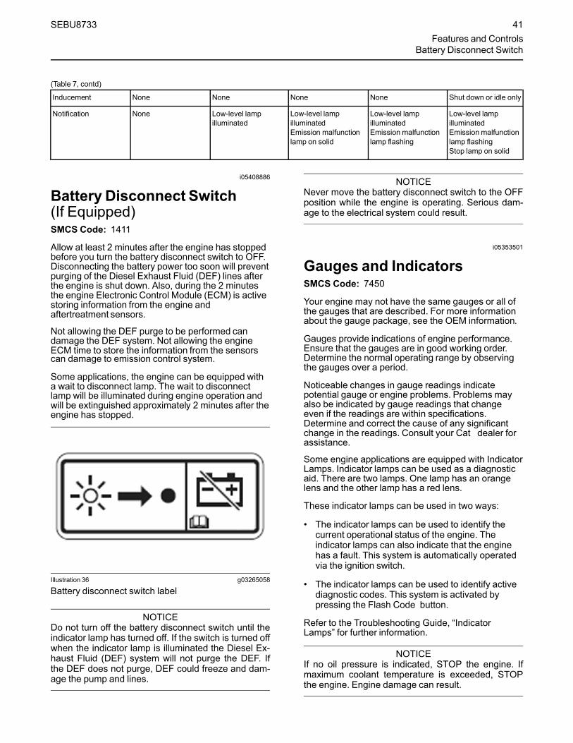
Illustration 36 g03265058
Battery disconnect switch label
NOTICEDo not turn off the battery disconnect switch until theindicator lamp has turned off. If the switch is turned offwhen the indicator lamp is illuminated the Diesel Ex-haust Fluid (DEF) system will not purge the DEF. Ifthe DEF does not purge, DEF could freeze and dam-age the pump and lines.
NOTICENever move the battery disconnect switch to the OFFposition while the engine is operating. Serious dam-age to the electrical system could result.
i05353501
Gauges and IndicatorsSMCS Code: 7450
Your engine may not have the same gauges or all ofthe gauges that are described. For more informationabout the gauge package, see the OEM information.
Gauges provide indications of engine performance.Ensure that the gauges are in good working order.Determine the normal operating range by observingthe gauges over a period.
Noticeable changes in gauge readings indicatepotential gauge or engine problems. Problems mayalso be indicated by gauge readings that changeeven if the readings are within specifications.Determine and correct the cause of any significantchange in the readings. Consult your Cat dealer forassistance.
Some engine applications are equipped with IndicatorLamps. Indicator lamps can be used as a diagnosticaid. There are two lamps. One lamp has an orangelens and the other lamp has a red lens.
These indicator lamps can be used in two ways:
• The indicator lamps can be used to identify thecurrent operational status of the engine. Theindicator lamps can also indicate that the enginehas a fault. This system is automatically operatedvia the ignition switch.
• The indicator lamps can be used to identify activediagnostic codes. This system is activated bypressing the Flash Code button.
Refer to the Troubleshooting Guide, “IndicatorLamps” for further information.
NOTICEIf no oil pressure is indicated, STOP the engine. Ifmaximum coolant temperature is exceeded, STOPthe engine. Engine damage can result.
SEBU8733 41Features and Controls
Battery Disconnect Switch

Engine Oil Pressure – The oil pressureshould be greatest after a cold engine isstarted. The typical engine oil pressure
with SAE10W40 is 350 to 450 kPa ( 50 to 65 psi) atrated rpm.
A lower oil pressure is normal at low idle. If the enginespeed and load are stable and the gauge readingchanges, perform the following procedure:
1. Remove the load.
2. Stop the engine.
3. Check and maintain the oil level.
Jacket Water Coolant Temperature –Typical temperature range is 82° to 94°C(179.6° to 169.2°F). This temperature
range will vary according to engine load and theambient temperature.
A 100 kPa (14.5 psi) radiator cap must be installedon the cooling system. The maximum temperature forthe cooling system is 108° C (226.4° F). Thistemperature is measured at the outlet for the watertemperature regulator. The engine coolanttemperature is regulated by the engine sensors andthe engine ECM. This programming cannot bealtered. Derates can occur if the maximum enginecoolant temperature is exceeded.
If the engine is operating above the normal range,reduce the engine load. If high coolant temperaturesare a frequent event, perform the followingprocedures:
1. Reduce the load on the engine.
2. Determine if the engine must be shut downimmediately or if the engine can be cooled byreducing the load.
3. Inspect the cooling system for leaks. If necessary,consult your Caterpillar dealer for assistance.
Tachometer – This gauge indicatesengine speed (rpm). When the throttlecontrol lever is moved to the full throttle
positionwithout load, the engine is running athigh idle. The engine is running at the full loadrpm when the throttle control lever is at the fullthrottle position with maximum rated load.
NOTICETo help prevent engine damage, never exceed thehigh idle rpm. Overspeeding can result in seriousdamage to the engine. Operation at speeds exceed-ing high idle rpm should be kept to a minimum.
Ammeter – This gauge indicates theamount of charge or discharge in thebattery charging circuit. Operation of the
indicator should be to the ““+”” side of ““0”” (zero).
Fuel Level – This gauge indicates thefuel level in the fuel tank. The fuel levelgauge operates when the ““START/
STOP”” switch is in the ““on”” position.
Service Hour Meter – The gaugeindicates total operating hours of theengine.
Indicator Lamps• Shutdown lamp
• Warning lamp
• Wait to start lamp (Glow plug warning lamp)
• Low oil pressure lamp
For information, refer to this manual, “MonitoringSystem (Table for the Indicator Lamps)” for thesequence of operation of the shutdown lamp and thewarning lamp.
The function of the wait to start lamp is automaticallycontrolled at engine start-up.
The function of the low oil pressure lamp is controlledby the engine ECM. If low oil pressure is detected, thelamp will be illuminated. The reason for theillumination of the low-pressure lamp should beinvestigated immediately.
All lamps will illuminate for 2 seconds in order tocheck that the lamps are functioning when thekeyswitch is turned to the ON position. If any of thelamps stay illuminated, or a lamp fails to beilluminated the reason should be investigatedimmediately.
The glow plug warning lamp will flash in order to showthat the engine is been held at low speed. Thisfunction will be performed at engine starting and theduration will depend on ambient temperature andengine temperature.
AftertreatmentLamps and gaugesAll applications will require the following lamps andgauges:
• Emission malfunction lamp
• Action indicator lamp
• Gauge for Diesel Exhaust Fluid (DEF)
• Low warning lamp for DEF
• Wait to disconnect lamp (optional)
42 SEBU8733Features and ControlsGauges and Indicators

The wait to disconnect lamp will be illuminated duringengine operation and will be extinguishedapproximately 2 minutes after the engine hasstopped. Do not disconnect the battery disconnectswitch during the period the lamp is illuminated. TheDEF system will be purged during this time. Also,during the 2 minutes the engine electronic controlmodule is active storing information from the engineand aftertreatment sensors.
Note: The wait to disconnect lamp will not bechecked at key on. The wait to disconnect lamp willilluminate at key on.
i04901303
Monitoring System(Engine Indicators andAftertreatment Indicators)SMCS Code: 1900; 7400; 7450; 7451
Engine Indicator LampsNote:When in operation the amber warning lamp hasthree states, solid, flashing, and fast flashing. Thesequence is to give a visual indication of theimportance of the warning. Some application canhave an audible warning installed.
Ensure that the engine maintenance is carried out atthe correct intervals. A lack of maintenance can resultin illumination of the warning lamp. For the correctintervals of maintenance, refer to the Operation andMaintenance Manual, “Maintenance IntervalSchedule”.Table 8
Indicator Lamp Table
WarningLamp
ShutdownAction Indi-cator Lamp
Lamp State Description of the Indication Engine Status
On On Lamp Check When the keyswitch is moved to the ON po-sition, the lamps come on for 2 seconds andthe lamps will then go off.
The keyswitch is in the ON position but the en-gine has not yet been cranked.
If any of the indicators will not illuminate during indicator check, the fault must be investigated immediatelyIf any Indicators stay illuminated or flash, the fault must be investigated immediately.
Off Off No Faults With the engine in operation, there are noactive warnings, diagnostic codes, or eventcodes.
The engine is operating with no detected faults.
On Solid Off Warning Level 1 warning The engine is operating normally but there isone or more faults with the electronic manage-ment system for the engine.
As soon as possible the fault should be investigated.
(continued)
SEBU8733 43Features and Controls
Monitoring System

(Table 8, contd)
Indicator Lamp Table
WarningLamp
ShutdownAction Indi-cator Lamp
Lamp State Description of the Indication Engine Status
Flashing Off Warning Level 2 warning The engine continues to be operated, but thelevel of importance of the warning hasincreased.Depending on the particular fault and the se-verity the engine may be de-rated.The engine could be damaged if continued tobe operated.
Stop the engine. Investigate the code.
Flashing On Engine Shutdown Level 3 warningIf both the warning lamp and the shutdownlamp are in operation, this issue indicatesone of the following conditions.
1. One or more of the shutdown values forthe engine protection strategy has beenexceeded.
2. A serious active diagnostic code has beendetected.
If install, the audible warning will sound.After a short time period, the engine mayshut down.
The engine is either shutdown or an engineshutdown is imminent. One or more monitoredengine parameters have exceeded the limit foran engine shutdown. This pattern of lamps canbe caused by the detection of a serious activediagnostic code.
Contact your Cat dealer.
Flash CodesSome applications may support flash codes. A flashcode can be viewed by an indicator lamp that whenasked will flash in a particular sequence. Theindicator lamp used to view the codes is the warninglamp, the lamp can then be refer to as a diagnosticlamp. For more information refer to this Operation andMaintenance Manual, “Diagnostic Lamp”.
AftertreatmentSystem
The aftertreatment indicators should illuminate at keyon for 2 seconds in order to test the system. If any ofthe indicators do not illuminate, the fault must beinvestigated immediately.
For more information on the illumination of theaftertreatment indicators refer to this Operation andMaintenance Manual, “Selective Catalytic ReductionWarning System”.
i03554501
OverspeedSMCS Code: 1900; 1907; 1912; 7427
• ECM Electronic Control Module
• RPM Revolutions Per Minute
An overspeed is detected by the speed/timingsensors.
The default setting for an overspeed is 3000 rpm. TheECM will cut the power to the electronic unit injectors,until the rpm drops below 200 rpm of the overspeedsetting. A diagnostic fault code will be logged into theECM memory and a warning lamp will indicate adiagnostic fault code.
An overspeed can be set from 2600 rpm to 3000 rpm.This setting depends on the application.
i05350563
Sensors and ElectricalComponentsSMCS Code: 1900; 7400
The illustrations within the following sections aretypical location of the sensors or electricalcomponents for an industrial engine. Specific enginesmay appear different due to differences inapplications.
44 SEBU8733Features and ControlsOverspeed
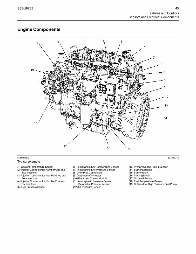
Engine Components
Illustration 37 g03389319
Typical example(1) Coolant Temperature Sensor(2) Injector Connector for Number One and
Two Injectors(3) Injector Connector for Number three and
Four Injectors(4) Injector Connector for Number Five and
Six Injectors(5) Fuel Pressure Sensor
(6) Inlet Manifold Air Temperature Sensor(7) Inlet Manifold Air Pressure Sensor(8) Glow Plug Connection(9) Diagnostic Connector(10) Electronic Control Module(11) Atmospheric Pressure Sensor
(Barometric Pressure sensor)(12) Oil Pressure Sensor
(13) Primary Speed/Timing Sensor(14) Starter Solenoid(15) Starter relay(16) Starting Motor(17) Oil Level Switch(18) Fuel Temperature Sensor(19) Solenoid for High Pressure Fuel Pump
SEBU8733 45Features and Controls
Sensors and Electrical Components

Illustration 38 g03389322
Typical example(20) Wastegate Regulator(21) Control Valve for the NOx Reduction
System (NRS)
(22) Temperature Sensor for the NRS(23) Intake Pressure for the NRS(24) Differential Pressure for the NRS
(25) Back Pressure Valve
46 SEBU8733Features and ControlsSensors and Electrical Components

Illustration 39 g03389323
Typical example(26) Alternator (27) Secondary Speed/Timing sensor (28) Exhaust Temperature Sensor
SEBU8733 47Features and Controls
Sensors and Electrical Components
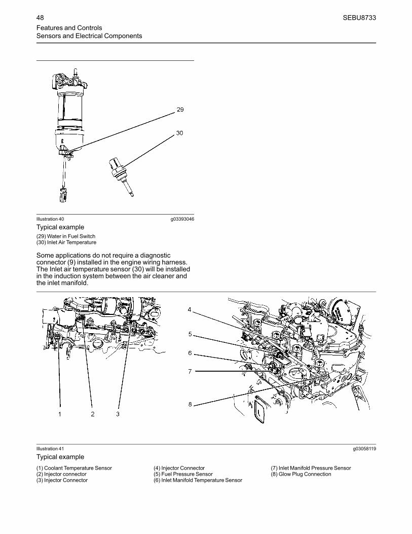
Illustration 40 g03393046
Typical example(29) Water in Fuel Switch(30) Inlet Air Temperature
Some applications do not require a diagnosticconnector (9) installed in the engine wiring harness.The Inlet air temperature sensor (30) will be installedin the induction system between the air cleaner andthe inlet manifold.
Illustration 41 g03058119
Typical example(1) Coolant Temperature Sensor(2) Injector connector(3) Injector Connector
(4) Injector Connector(5) Fuel Pressure Sensor(6) Inlet Manifold Temperature Sensor
(7) Inlet Manifold Pressure Sensor(8) Glow Plug Connection
48 SEBU8733Features and ControlsSensors and Electrical Components

Illustration 42 g03393011
Typical example(9) Diagnostic connector(10) Electronic Control Module(11) Atmospheric Pressure Sensor (Barometric Pressure sensor)(12) Oil pressure sensor
Illustration 43 g03392999
Typical example(13) Primary Speed/Timing Sensor
SEBU8733 49Features and Controls
Sensors and Electrical Components

Illustration 44 g03393000
Typical example(14) Starter Solenoid(15) Starting Motor
(16) Starter Relay(17) Oil Level Switch
Illustration 45 g03393004
Typical example(18) Fuel Temperature Sensor(19) Solenoid for High Pressure Fuel Pump
50 SEBU8733Features and ControlsSensors and Electrical Components

Illustration 46 g03393005
Typical example(20) Wastegate Regulator(21) Control Valve for NRS
(22) Temperature Sensor for the NRS(23) Intake Pressure for the NRS
(24) Differential Pressure for the NRS
SEBU8733 51Features and Controls
Sensors and Electrical Components

Illustration 47 g03393010
Typical example(25) Back Pressure valve(26) Alternator
52 SEBU8733Features and ControlsSensors and Electrical Components

Illustration 48 g03393006
Typical example(27) Secondary Speed/Timing sensor(28) Exhaust Temperature Sensor
SEBU8733 53Features and Controls
Sensors and Electrical Components

AftertreatmentComponents
Illustration 49 g03393078
Clean EmissionsModule (CEM)
Illustration 50 g03393624
(1) Clean Emission Module(2) Gas Intake Temperature Sensor(3) Soot Sensor Antenna(4) Location for NOx Sensing Element(5) Soot Sensor Antenna(6) Diesel Exhaust Fluid Injector(7) Temperature Sensor Connector(8) Identification Module(9) Gas Temperature Sensor before Selective Catalytic Reduction
54 SEBU8733Features and ControlsSensors and Electrical Components

CEM Sensors
Illustration 51 g03393632
(2) Gas Intake Temperature Sensor(3) Soot Sensor Antenna
(4) Location for NOx Sensing Element(5) Soot Sensor Antenna
(6) Diesel Exhaust Fluid Injector
Illustration 52 g03393634
(7) Temperature Sensor Connector(8) Identification Module
(9) Gas TemperatureSensor beforeSelective Catalytic Reduction
SEBU8733 55Features and Controls
Sensors and Electrical Components

Soot and NOx Sensors
Illustration 53 g03393956
(10) Soot Sensor (11) NOx Sensors
The location of the soot sensor (10) and NOx sensor(11) will depend on the application.
56 SEBU8733Features and ControlsSensors and Electrical Components

Pump Electronic Tank Unit (PETU)
Illustration 54 g03393959
(1) DEF Level Sensor and DEF TemperatureSensor
(2) Coolant Diverter Valve
(3) Customer Connections(4) Dosing Control Module(5) Relays
(6) Voltage Limiting ProtectionModule
SEBU8733 57Features and Controls
Sensors and Electrical Components
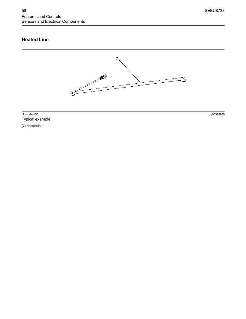
Heated Line
Illustration 55 g03393960
Typical example(7) Heated line
58 SEBU8733Features and ControlsSensors and Electrical Components

Engine Diagnosticsi01796959
Self-DiagnosticsSMCS Code: 1000; 1900; 1901; 1902
Caterpillar Electronic Engines have the capability toperform a self-diagnostics test. When the systemdetects an active problem, a diagnostic lamp isactivated. Diagnostic codes will be stored inpermanent memory in the Electronic Control Module(ECM). The diagnostic codes can be retrieved byusing Caterpillar electronic service tools.
Some installations have electronic displays thatprovide direct readouts of the engine diagnosticcodes. Refer to the manual that is provided by theOEM for more information on retrieving enginediagnostic codes.
Active codes represent problems that currently exist.These problems should be investigated first.
Logged codes represent the following items:
• Intermittent problems
• Recorded events
• Performance history
The problems may have been repaired since thelogging of the code. These codes do not indicate thata repair is needed. The codes are guides or signalswhen a situation exists. Codes may be helpful totroubleshoot problems.
When the problems have been corrected, thecorresponding logged fault codes should be cleared.
i03554520
Diagnostic LampSMCS Code: 1000; 1900; 1901; 1902; 7451
A diagnostic lamp is used to indicate the existence ofan active fault. A fault diagnostic code will remainactive until the problem is repaired. The diagnosticcode may be retrieved by using the electronic servicetool.
i04907245
Diagnostic Flash CodeRetrievalSMCS Code: 1000; 1900; 1901; 1902
Use the following procedure to retrieve the flashcodes if the engine is equipped with a“DIAGNOSTIC” lamp:
1.Move the keyswitch from the on/off two times within3 seconds.
2. The shutdown warning lamp will flash once.
3. A flashing YELLOW lamp indicates a 3-digitdiagnostic code for the engine. The sequence offlashes represents the system diagnosticmessage. Count the first sequence of flashes inorder to determine the first digit of the flash code.After a two second pause, the second sequence offlashes will identify the second digit of the flashcode. After the second pause, the third sequenceof flashes will identify the flash code.
4. After the diagnostic codes have been displayed,the shutdown lamp will flash twice and theindicator lamp will start to flash the loggeddiagnostic codes.
5. After the logged diagnostic codes have beendisplayed, the shutdown lamp will flash three timesin order to indication that the code sequences havefinished.
Note: If there are no diagnostic codes or loggeddiagnostic codes, the system will flash the code 551.
i05406659
Fault LoggingSMCS Code: 1000; 1900; 1901; 1902
The system provides the capability of Fault Logging.When the Electronic Control Module (ECM)generates an active diagnostic code, the code will belogged in the memory of the ECM. The codes thathave been logged by the ECM can be identified bythe electronic service tool. The active codes that havebeen logged will be cleared when the fault has beenrectified or the fault is no longer active. The followinglogged faults cannot be cleared from the memory ofthe ECM without using a factory password:Overspeed, low engine oil pressure, high enginecoolant temperature, and aftertreatment codes.
i03554534
Engine Operationwith ActiveDiagnostic CodesSMCS Code: 1000; 1900; 1901; 1902
If a diagnostic lamp illuminates during normal engineoperation, the system has identified a situation that isnot within the specification. Use electronic servicetools to check the active diagnostic codes.
SEBU8733 59Engine Diagnostics
Self-Diagnostics
Note: If the customer has selected “DERATE” and ifthere is a low oil pressure condition, the ElectronicControl Module (ECM) will limit the engine power untilthe problem is corrected. If the oil pressure is withinthe normal range, the engine may be operated at therated speed and load. However, maintenance shouldbe performed as soon as possible.
The active diagnostic code should be investigated.The cause of the problem should be corrected assoon as possible. If the cause of the active diagnosticcode is repaired and there is only one activediagnostic code, the diagnostic lamp will turn off.
Operation of the engine and performance of theengine can be limited as a result of the activediagnostic code that is generated. Acceleration ratesmay be significantly slower. Refer to theTroubleshooting Guide for more information on therelationship between these active diagnostic codesand engine performance.
i01797063
Engine OperationwithIntermittent Diagnostic CodesSMCS Code: 1000; 1900; 1901; 1902
If a diagnostic lamp illuminates during normal engineoperation and the diagnostic lamp shuts off, anintermittent fault may have occurred. If a fault hasoccurred, the fault will be logged into the memory ofthe Electronic Control Module (ECM).
In most cases, it is not necessary to stop the enginebecause of an intermittent code. However, theoperator should retrieve the logged fault codes andthe operator should reference the appropriateinformation in order to identify the nature of the event.The operator should log any observation that couldhave caused the lamp to light.
• Low power
• Limits of the engine speed
• Excessive smoke, etc
This information can be useful to help troubleshootthe situation. The information can also be used forfuture reference. For more information on diagnosticcodes, refer to the Troubleshooting Guide for thisengine.
i05402551
Configuration ParametersSMCS Code: 1000; 1900; 1901; 1902
The engine electronic control module (ECM) has twotypes of configuration parameters. The systemconfiguration parameters and the customer specifiedparameters.
The electronic service tool is required in order to alterthe configuration parameters.
System ConfigurationParametersSystem configuration parameters affect the emissionsof the engine or the power of the engine. Systemconfiguration parameters are programmed at thefactory. Normally, system configuration parameterswould never require changing through the life of theengine. System configuration parameters must bereprogrammed if an ECM is replaced. Systemconfiguration parameters do not requirereprogrammed if the ECM software is changed.Factory passwords are required to change theseparameters.
60 SEBU8733Engine DiagnosticsEngine Operation with Intermittent Diagnostic Codes

Table 9
SystemConfiguration Parameters
Configuration Parameters Record
Engine Serial Number
Factory Installed Aftertreatment #1 Identification Number
DPF #1 Soot Loading Sensing System Configuration Code
Limp Home Engine Speed Ramp Rate
System Operating Voltage Configuration
Rating Number
CAN Communication Protocol Write Security
Engine Emissions Operator Inducement Progress Configuration
Engine Emissions Operator Inducement Regulation Configuration
Customer Specified ParametersCustomer specified parameters allow the engine tobe configured to the exact needs of the application.
The electronic service tool is required in order to alterthe customer configuration parameters.
Customer parameters may be changed repeatedly asoperational requirements change.Table 10
Customer Specified Parameters
Specified Parameters Record
Throttle Type Channel 1
Throttle Type Channel 2
IVS Channel 1
IVS Channel 2
Continuous Position Throttle Configuration 1
Continuous Position Throttle Configuration 2
Multi Position Throttle Switch Configuration
Throttle Arbitration
Equipment ID
Low Idle Speed
Delay Engine Shutdown
Ether Solenoid Configuration
Engine Idle ShutdownMinimumAmbient Air Temperature
Engine Idle ShutdownMaximumAmbient Air Temperature
Engine Idle Shutdown Enable Status
Engine Idle Shutdown Delay Time
(continued)
SEBU8733 61Engine Diagnostics
Configuration Parameters

(Table 10, contd)
Engine Idle Shutdown Ambient TemperatureOverride Enable Status
High Soot Load Aftertreatment Protection Enable Status
Air Shutoff
Throttle Lock Feature Installation Status
PTO Mode
Throttle Lock Engine Set Speed #1
Throttle Lock Engine Set Speed #2
Throttle Lock Increment Speed Ramp Rate
Throttle Lock Decrement Speed Ramp Rate
Throttle Lock Engine Set Speed Increment
Throttle Lock Engine Set Speed Decrement
Monitoring Mode Shutdowns
Monitoring Mode Derates
Limp Home Desired Engine Speed
Engine Acceleration Rate
Engine Speed Decelerating Ramp Rate
Intermediate Engine Speed
Fan
Engine Fan Control
Engine Fan Type Configuration
Engine Cooling Fan Temperature Error Increasing Hysteresis
Engine Cooling Fan Temperature Error Decreasing Hysteresis
Engine Cooling Fan Current Ramp Rate
Engine Cooling Fan Speed
Top Engine Fan Speed
Minimum Desired Engine Cooling Fan Speed
Engine Cooling Fan Solenoid MinimumCurrent
Engine Cooling Fan Solenoid MaximumCurrent
Engine cooling Fan solenoid Dither Frequency
Engine Cooling Fan Solenoid Dither Amplitude
Fan Temperatures
Engine Fan Control Charge Air Cooler Outlet Temperature Input Enable
Engine Cooling Fan MaximumAir Flow Charge Air Cooler Outlet Temperature
Engine Cooling Fan MinimumAir Flow Charge Air Cooler Outlet Temperature
Engine Cooling Fan Control Coolant Temperature Input Enable Status
Engine Cooling Fan MaximumAir Flow Coolant Temperature
(continued)
62 SEBU8733Engine DiagnosticsConfiguration Parameters

(Table 10, contd)
Engine Cooling Fan MinimumAir Flow Coolant Temperature
Engine Cooling Fan Control Transmission Oil Temperature Input Enable Status
Engine Cooling Fan MaximumAir Flow Transmission Oil Temperature
Engine Cooling Fan MinimumAir Flow Transmission Oil Temperature
Engine Cooling Fan Control Hydraulic Oil Temperature Input Enable Status
Engine Cooling Fan MaximumAir Flow Hydraulic Oil Temperature
Engine Cooling Fan MinimumAir Flow Hydraulic Oil Temperature
Engine Cooling Fan Control Auxiliary #1 Temperature Input Enable Status
Engine Cooling Fan MaximumAir Flow Auxiliary #1 Temperature
Engine Cooling Fan MinimumAir Flow Auxiliary #1 Temperature
Engine Cooling Fan Control Auxiliary #2 Temperature Input Enable Status
Engine Cooling Fan MaximumAir Flow Auxiliary #2 Temperature
Engine Cooling Fan MinimumAir Flow Auxiliary #2 Temperature
Other Parameters
Maintenance Indicator Mode
Maintenance Level 1 Cycle Interval Hours
Coolant Level Sensor
Air Filter Restriction Switch Installation Status
Air Filter Restriction Switch Configuration
Fuel/Water Separator Switch Installation Status
User Defined Switch Installation Status
Auxiliary Temperature Sensor Installation Status
Auxiliary Pressure Sensor Installation Status
Remote Torque Speed Control Enable Status
Number of Engine Operating Mode Switches
Engine OperatingMode Configuration
Glow Plug Start Aid Installation Status
High Idle Configuration
Throttle Channel 1 Droop%
Throttle Channel 2 Droop%
TSC 1 Droop %
Min Max / All Speed Governing
Rated Speed Configuration
SEBU8733 63Engine Diagnostics
Configuration Parameters

Engine Startingi04935860
Before Starting EngineSMCS Code: 1000; 1400; 1450
Perform the required daily maintenance and otherperiodic maintenance before the engine is started.Inspect the engine compartment. This inspection canhelp prevent major repairs at a later date. Refer to theOperation and Maintenance Manual, “MaintenanceInterval Schedule” for more information.
• Ensure that the engine has an adequate fuelsupply.
• Ensure that the engine has an adequate dieselexhaust fluid supply
• Open the fuel supply valve (if equipped).
NOTICEAll valves in the fuel return line must be open and fuelsupply lines must be open. Damage to the fuel sys-tem can occur if fuel lines are closed with the enginein operation.
If the engine has not been started for several weeks,fuel may have drained from the fuel system. Air mayhave entered the filter housing. Also, when fuel filtershave been changed, some air pockets will be trappedin the engine. In these instances, prime the fuelsystem. Refer to the Operation and MaintenanceManual, “Fuel System - Prime” for more informationon priming the fuel system. Also, check that the fuelspecification is correct and that the fuel condition iscorrect. Refer to the Operation and MaintenanceManual, “Fuel Recommendations”.
Engine exhaust contains products of combustionwhich may be harmful to your health. Always startand operate the engine in a well ventilated areaand, if in an enclosed area, vent the exhaust to theoutside.
• Do not start the engine or move any of the controlsif there is a “DO NOT OPERATE” warning tag orsimilar warning tag attached to the start switch orto the controls.
• Reset all of the shutoffs or alarm components.
• Ensure that any driven equipment has beendisengaged. Minimize electrical loads or removeany electrical loads.
i05354321
Cold Weather StartingSMCS Code: 1000; 1250; 1450; 1453; 1456; 1900
Do not use aerosol types of starting aids such asether. Such use could result in an explosion andpersonal injury.
Startability will be improved at temperatures below−18 °C (0 °F) from the use of a jacket water heater orextra battery capacity.
The following items provide a means of minimizingstarting problems and fuel problems in cold weather:Engine oil pan heaters, jacket water heaters, fuelheaters and fuel line insulation. For more information,refer to Commercial Diesel Engine FluidsRecommendations , SEBU6251.
Use the procedure that follows for cold weatherstarting.
Note: Do not adjust the engine speed control duringstart-up. The electronic control module (ECM) willcontrol the engine speed during start-up.
1. Disengage any driven equipment.
2. Turn the keyswitch to the RUN position. Leave thekeyswitch in the RUN position until the warninglight for the glow plugs is extinguished.
NOTICEDo not engage the starting motor when flywheel isturning. Do not start the engine under load.
If the engine fails to start within 30 seconds, releasethe starter switch or button and wait two minutes to al-low the starting motor to cool before attempting tostart the engine again.
3.When the warning light for the glow plugs isextinguished cycle the keyswitch. Turn thekeyswitch to the OFF position and then to theSTART position in order to engage the electricstarting motor and crank the engine.
Note: The operating period of the warning light for theglow plugs will change due to the temperature of theengine.4. Allow the keyswitch to return to the RUN position
after the engine starts.
5. Repeat step 2 through step 4 if the engine fails tostart.
64 SEBU8733Engine StartingBefore Starting Engine

Note: After starting, the engine may be held at lowspeed for a duration between 1 and 25 seconds toallow engine systems to stabilize. The duration willdepend on ambient temperature, time since last runand other factors. The glow plug warning lamp willflash in order to indicate that the engine is been heldat low speed.6. The engine should not be “raced” in order to speed
up the warm-up process. Allow the engine to idlefor 3 to 5 minutes, or allow the engine to idle untilthe water temperature indicator begins to rise.When idling after the engine has started in coldweather, increase the engine rpm from 1000 to1200 rpm. This procedure will warm up the enginemore quickly.
7. Operate the engine at low load until all systemsreach operating temperature. Check the gaugesduring the warm-up period.
Following a cold start white smoke can be seen fromthe tailpipe. This smoke is normal and caused bycondensation leaving the exhaust system afterwarming up. The white smoke should clear followingworking of the engine.
i05354322
Starting the EngineSMCS Code: 1000; 1450
Note:Do not adjust the engine speed control duringstart-up. The electronic control module (ECM) willcontrol the engine speed during start-up.
Starting the Engine1. Disengage any equipment that is driven by the
engine.
2. Turn the keyswitch to the RUN position. Leave thekeyswitch in the RUN position until the warninglight for the glow plugs is extinguished.
Note:During the key on, the indicator lamps will beilluminated for 2 seconds in order to check lampoperation. If any of the lamps do not illuminate, checkthe bulb. If any indicator lamps stay illuminated orflash, refer to Troubleshooting, “Indicator LampCircuit - Test”.3.When the warning light for the glow plugs is
extinguished cycle the keyswitch. Turn thekeyswitch to the OFF position and then to theSTART position in order to engage the electricstarting motor and crank the engine.
Note: The operating period of the warning light for theglow plugs will change due to the temperature of theengine.
NOTICEDo not engage the starting motor when flywheel isturning. Do not start the engine under load.
If the engine fails to start within 30 seconds, releasethe starter switch or button and wait two minutes to al-low the starting motor to cool before attempting tostart the engine again.
4. Allow the keyswitch to return to the RUN positionafter the engine starts.
5. Repeat step 2 through step 4 if the engine fails tostart.
6. After starting, the engine may be held at low speedfor a duration between 1 and 25 seconds to allowengine systems to stabilize. The duration willdepend on ambient temperature, time since lastrun and other factors. The glow plug warning lightwill flash in order to indicate that the engine is beenheld at low speed.
i03653722
Starting with Jump StartCablesSMCS Code: 1000; 1401; 1402; 1900
Improper jump start cable connections can causean explosion resulting in personal injury.
Prevent sparks near the batteries. Sparks couldcause vapors to explode. Do not allow jump startcable ends to contact each other or the engine.
If the installation is not equipped with a backupbattery system, it may be necessary to start theengine from an external electrical source.
For information on troubleshooting the chargingsystem, refer to Special Instruction, REHS0354,“Charging System Troubleshooting”.
Many batteries which are considered unusable arestill rechargeable. After jump starting, the alternatormay not be able to fully recharge batteries that areseverely discharged. The batteries must be chargedto the proper voltage with a battery charger. Forinformation on testing and charging, refer to theSpecial Instruction, SEHS7633, “Battery TestProcedure”.
SEBU8733 65Engine Starting
Starting the Engine
NOTICEUsing a battery source with the same voltage as theelectric starting motor. Use ONLY equal voltage forjump starting. The use of higher voltage will damagethe electrical system.
Do not reverse the battery cables. The alternator canbe damaged. Attach ground cable last and removefirst.
When using an external electrical source to start theengine, turn the generator set control switch to the“OFF” position. Turn all electrical accessories OFFbefore attaching the jump start cables.
Ensure that the main power switch is in the OFF posi-tion before attaching the jump start cables to the en-gine being started.
1. Turn the start switch on the stalled engine to theOFF position. Turn off all the engine's accessories.
2. Connect one positive end of the jump start cable tothe positive cable terminal of the dischargedbattery. Connect the other positive end of the jumpstart cable to the positive cable terminal of theelectrical source.
3. Connect one negative end of the jump start cableto the negative cable terminal of the electricalsource. Connect the other negative end of thejump start cable to the engine block or to thechassis ground. This procedure helps to preventpotential sparks from igniting the combustiblegases that are produced by some batteries.
Note: The engine ECM must be powered before thestarting motor is operated or damage can occur.4. Start the engine in the normal operating procedure.
Refer to this Operation and Maintenance Manual,“Starting the Engine”.
5. Immediately after the engine is started, disconnectthe jump start cables in reverse order.
After jump starting, the alternator may not be able tofully recharge batteries that are severely discharged.The batteries must be replaced or charged to theproper voltage with a battery charger after the engineis stopped. Many batteries which are consideredunusable are still rechargeable. Refer to Operationand Maintenance Manual, “Battery - Replace” andTesting and Adjusting Manual, “Battery - Test”.
Refer to the Electrical Schematic for your engine.Consult your Caterpillar dealer for more information.
i05354355
After Starting EngineSMCS Code: 1000
After starting, the engine may be held at low speedfor a duration between 1 and 25 seconds to allowengine systems to stabilize. The duration will dependon ambient temperature, time since last run and otherfactors.
Note: In ambient temperatures from 0 to 60°C(32 to 140°F), the warm-up time is approximately 3minutes. In temperatures below 0°C (32°F),additional warm-up time may be required.
When the engine idles during warm-up, observe thefollowing conditions:
Do not check the high-pressure fuel lines with theengine or the starting motor in operation. If youinspect the engine in operation, always use theproper inspection procedure in order to avoid a fluidpenetration hazard. Refer to Operation andMaintenance Manual, “General hazard Information”.
• Check for any fluid or for any air leaks at idle rpmand at one-half full rpm (no load on the engine)before operating the engine under load. This checkmay not possible in some applications.
• Allow the engine to idle for 3 to 5 minutes, or allowthe engine to idle until the water temperatureindicator begins to rise. Check all gauges duringthe warm-up period.
Note:Gauge readings should be observed and thedata should be recorded frequently while the engineis operating. Comparing the data over time will help todetermine normal readings for each gauge.Comparing data over time will also help detectabnormal operating developments. Significantchanges in the readings should be investigated.
66 SEBU8733Engine StartingAfter Starting Engine

Engine Operationi04907268
Engine OperationSMCS Code: 1000
Proper operation and maintenance are key factors inobtaining the maximum life and economy of theengine. If the directions in the Operation andMaintenance Manual are followed, costs can beminimized and engine service life can be maximized.
The time that is needed for the engine to reachnormal operating temperature can be less than thetime taken for a walk-around inspection of the engine.
The engine can be operated at the rated rpm after theengine is started and after the engine reachesoperating temperature. The engine will reach normaloperating temperature sooner during a low enginespeed (rpm) and during a low-power demand. Thisprocedure is more effective than idling the engine atno load. The engine should reach operatingtemperature in a few minutes.
Avoid excess idling. Excessive idling causes carbonbuildup, engine slobber and soot loading of theDiesel Particulate Filter (DPF). These issues areharmful to the engine.
Gauge readings should be observed and the datashould be recorded frequently while the engine isoperating. Comparing the data over time will help todetermine normal readings for each gauge.Comparing data over time will also help detectabnormal operating developments. Significantchanges in the readings should be investigated.
Engine Operation and theAftertreatmentSystemThe exhaust gases and hydrocarbon particles fromthe engine first pass through Diesel OxidationCatalyst (DOC). Some of the gasses and matter areoxidized as they pass through the DOC. The gassesthen pass through the Diesel Particulate Filter (DPF).The DPF collects the soot and any ash that isproduced by the combustion in the engine. Duringregeneration, the soot is converted into a gas and theash remains in the DPF. The gasses finally passthrough the Selective Catalytic Reduction (SCR).Before the gasses pass through the SCR, DieselExhaust Fluid (DEF) is injected into the gas stream.The DEF is stored and controlled by the PumpElectronic Tank Unit (PETU). The mixtures of DEFand the exhaust gas pass through the SCR reducingthe NOx in the exhaust emissions.
The DPF may require the exhaust gas temperature torise in order to remove the soot. If necessary, theback pressure valve operates in order to create therise in temperature. In some applications, theoperation of the back pressure valve will make theengine tone different.
The engine software will control the amount of DEFthat will be required in order to keep the exhaustemission compliant.
This design of DPF will not require a servicemaintenance interval. The DPF can be expected tofunction properly for the useful life of the engine(emissions durability period), as defined byregulation, subject to prescribed maintenancerequirements being followed.
i01646335
Engaging the DrivenEquipmentSMCS Code: 1000
1. Operate the engine at one-half of the rated rpm,when possible.
2. Engage the driven equipment without a load on theequipment, when possible.
Interrupted starts put excessive stress on the drivetrain. Interrupted starts also waste fuel. To get thedriven equipment in motion, engage the clutchsmoothly with no load on the equipment. Thismethod should produce a start that is smooth andeasy. The engine rpm should not increase and theclutch should not slip.
3. Ensure that the ranges of the gauges are normalwhen the engine is operating at one-half of therated rpm. Ensure that all gauges operate properly.
4. Increase the engine rpm to the rated rpm. Alwaysincrease the engine rpm to the rated rpm beforethe load is applied.
5. Apply the load. Begin operating the engine at lowload. Check the gauges and equipment for properoperation. After normal oil pressure is reached andthe temperature gauge begins to move, the enginemay be operated at full load. Check the gaugesand equipment frequently when the engine isoperated under load.
Extended operation at low idle or at reduced loadmay cause increased oil consumption and carbonbuildup in the cylinders. This carbon buildupresults in a loss of power and/or poor performance.
SEBU8733 67Engine OperationEngine Operation

i04018250
Fuel ConservationPracticesSMCS Code: 1000; 1250
The efficiency of the engine can affect the fueleconomy. Caterpillar's design and technology inmanufacturing provides maximum fuel efficiency in allapplications. Follow the recommended procedures inorder to attain optimum performance for the life of theengine.
• Avoid spilling fuel.
Fuel expands when the fuel is warmed up. The fuelmay overflow from the fuel tank. Inspect fuel lines forleaks. Repair the fuel lines, as needed.
• Be aware of the properties of the different fuels.Use only the recommended fuels. Refer to theOperations and Maintenance Manual, “FuelRecommendations”for further information.
• Avoid unnecessary idling.
Shut off the engine rather than idle for long periods oftime.
• Observe the service indicator frequently. Keep theair cleaner elements clean.
• Ensure that the turbocharger is operating correctly.For more information refer to this Operation andMaintenance Manual, “Turbocharger - Inspect”.
• Maintain a good electrical system.
One faulty battery cell will overwork the alternator.This fault will consume excess power and excessfuel.
• The belt should be in good condition. Refer to theSystems Operation, Testing and Adjusting, “V -Belt Test” for further information.
• Ensure that all of the connections of the hoses aretight. The connections should not leak.
• Ensure that the driven equipment is in goodworking order.
• Cold engines consume excess fuel. Utilize heatfrom the jacket water system and the exhaustsystem, when possible. Keep cooling systemcomponents clean and keep cooling systemcomponents in good repair. Never operate theengine without water temperature regulators. All ofthese items will help maintain operatingtemperatures.
68 SEBU8733Engine OperationFuel Conservation Practices

Cold Weather Operationi05353504
ColdWeather OperationSMCS Code: 1000; 1250
Caterpillar Diesel Engines can operate effectively incold weather. During cold weather, the starting andthe operation of the diesel engine is dependent on thefollowing items:
• The type of fuel that is used
• The viscosity of the engine oil
• The operation of the glow plugs
• Optional Cold starting aid
• Battery condition
• Ambient air temperature
Refer to Special Publication, SEBU5898, ColdWeather Recommendations for CaterpillarMachines.
This section will cover the following information:
• Potential problems that are caused by cold-weather operation
• Suggest steps which can be taken in order tominimize starting problems and operatingproblems when the ambient air temperature isbetween “0° to −40 °C (32° to -40 °F)”.
The operation and maintenance of an engine infreezing temperatures is complex . This complexity isbecause of the following conditions:
• Weather conditions
• Engine applications
Recommendations from your Caterpillar dealer arebased on past proven practices. The information thatis contained in this section provides guidelines forcold-weather operation.
Hints for Cold Weather Operation• After starting the engine, the engine speed will be
governed for up to a maximum of 25 seconds.After this period, the engine should be operated atlow loads until a minimum operating temperatureof 80° C (176° F) is achieved
• Achieving operating temperature will help preventthe intake valves and exhaust valves from sticking.
• The cooling system and the lubrication system forthe engine do not lose heat immediately uponshutdown. This means that an engine can be shutdown for a period and the engine can still startreadily.
• Install the correct specification of engine lubricantbefore the beginning of cold weather.
• Check all rubber parts (hoses, fan drive belts)weekly.
• Check all electrical wiring and connections for anyfraying or damaged insulation.
• Keep all batteries fully charged and warm.
• Fill the fuel tank at the end of each shift.
• Drain the water from the fuel system. Refer to thisOperation and Maintenance Manual, “Fuel SystemPrimary Filter/Water Separator - Drain”.
• Check the air cleaners and the air intake daily.Check the air intake more often when you operatein snow.
• Ensure that the glow plugs are in working order.Refer to Troubleshooting, “Glow Plug Starting Aid -Test”.
Personal injury or property damage can resultfrom alcohol or starting fluids.
Alcohol or starting fluids are highly flammableand toxic and if improperly stored could result ininjury or property damage.
Do not use aerosol types of starting aids such asether. Such use could result in an explosion andpersonal injury.
• For jump starting with cables in cold weather, referto the Operation and Maintenance Manual,“Starting with Jump Start Cables.” for instructions.
SEBU8733 69Cold Weather OperationCold Weather Operation

Viscosity of the Engine LubricationOilCorrect engine oil viscosity is essential. Oil viscosityaffects the amount of torque that is needed to crankthe engine. Refer to this Operation and MaintenanceManual, “Fluid Recommendations” for therecommended viscosity of oil.
Recommendations for the CoolantProvide cooling system protection for the lowestexpected outside temperature. Refer to thisOperation and Maintenance Manual, “FluidRecommendations” for the recommended coolantmixture.
In cold weather, check the coolant often for thecorrect glycol concentration in order to ensureadequate freeze protection.
Engine Block Heaters
Engine block heaters (if equipped) heat the enginejacket water that surrounds the combustionchambers. This heat provides the following functions:
• Startability is improved.
• Warm up time is reduced.
An electric block heater can be activated once theengine is stopped. A block heater can be 110V dc or240V dc. The output can be 750/1000W. Consult yourCat dealer for more information.
Idling the EngineAfter starting the engine, the engine speed will begoverned for a maximum period of 25 seconds. Whenidling after the engine is started in cold weather,increase the engine rpm from 1000 to 1200 rpm. Thisincrease in RPM will warm up the engine morequickly. Maintaining an elevated low idle speed forextended periods will be easier with the installation ofa hand throttle. The engine should not be “raced” inorder to speed up the warm-up process.
While the engine is idling, the application of a lightload (parasitic load) will assist in achieving theminimum operating temperature. The minimumoperating temperature is 80° C (176° F).
Recommendations for CoolantWarm UpWarm up an engine that has cooled below normaloperating temperatures due to inactivity. Thisprocedure should be performed before the engine isreturned to full operation. During operation in verycold temperature conditions, damage to engine valvemechanisms can result from engine operation forshort intervals. This damage can happen if the engineis started and the engine is stopped many timeswithout being operated in order to warm upcompletely.
When the engine is operated below normal operatingtemperatures, fuel and oil are not completely burnedin the combustion chamber. This fuel and oil causessoft carbon deposits to form on the valve stems.Generally, the deposits do not cause problems andthe deposits are burned off during operation at normalengine operating temperatures.
When the engine is started and the engine is stoppedmany times without being operated in order to warmup completely, the carbon deposits become thicker.This carbon can cause the following problems:
• Free operation of the valves is prevented.
• Valves become stuck.
• Pushrods may become bent.
• Other damage to valve train components canresult.
For this reason, when the engine is started, theengine must be operated until the coolanttemperature is 80° C (176° F) minimum. Carbondeposits on the valve stems will be kept at a minimumand the free operation of the valves and the valvecomponents will be maintained.
The engine must be thoroughly warmed in order tokeep other engine parts in better condition. Also, theservice life of the engine will be generally extended.Lubrication will be improved. There will be less acidand less sludge in the oil. This improvement willprovide longer service life for the engine bearings, thepiston rings, and other parts. However, limitunnecessary idle time to 10 minutes in order toreduce wear and unnecessary fuel consumption.
70 SEBU8733Cold Weather OperationCold Weather Operation

The Water Temperature Regulator andInsulated Heater LinesThe engine is equipped with a water temperatureregulator. When the engine coolant is below thecorrect operating temperature, jacket water circulatesthrough the engine cylinder block and into the enginecylinder head. The coolant then returns to the cylinderblock via an internal passage that bypasses the valveof the coolant temperature regulator. This coolantreturn circuit ensures that coolant flows around theengine under cold operating conditions. The watertemperature regulator begins to open when theengine jacket water has reached the correct minimumoperating temperature. As the jacket water coolanttemperature rises above the minimum operatingtemperature the water temperature regulator opensfurther allowing more coolant through the radiator todissipate excess heat.
The progressive opening of the water temperatureregulator operates the progressive closing of thebypass passage between the cylinder block andhead. This process ensures maximum coolant flow tothe radiator in order to achieve maximum heatdissipation.
Note:Do not restrict the air flow. Restriction to the airflow can damage the fuel system. Caterpillar stronglydiscourages the use of all air flow restriction devicessuch as radiator shutters. Restriction of the air flowcan result in the following: high exhausttemperatures, power loss, excessive fan usage andreduction in fuel economy.
A cab heater is beneficial in very cold weather. Thefeed from the engine and the return lines from the cabshould be insulated in order to reduce heat loss to theoutside air.
Insulating the Air Inlet and EngineCompartment
When temperatures below −18 °C (−0 °F) will befrequently encountered, an air cleaner inlet that islocated in the engine compartment may be specified.An air cleaner that is located in the enginecompartment may also minimize the entry of snowinto the air cleaner. Also, heat that is rejected by theengine helps to warm the intake air.
Additional heat can be retained around the engine byinsulating the engine compartment.
Recommendation for Crankcase BreatherProtectionCrankcase ventilation gases contain a large quantityof water vapor. This water vapor can freeze in coldambient conditions and can plug or damage thecrankcase ventilation system. If the engine isoperated in temperatures below −25° C (−13° F),measures must be taken to prevent freezing andplugging of the breather system. Insulated hoses anda heated canister assembly should be installed.
Consult with your Cat dealer for the recommendedbreather components for operation from−25° to -40°C (−13° to -40.°F).
i04156663
Radiator RestrictionsSMCS Code: 1353; 1396
Caterpillar discourages the use of airflow restrictiondevices that are mounted in front of radiators. Airflowrestriction can cause the following conditions:
• High exhaust temperatures
• Power loss
• Excessive fan usage
• Reduction in fuel economy
Reducing air flow over components will also affectunder hood temperatures. Reducing air flow canincrease surface temperatures during anaftertreatment regeneration and could affectcomponent reliability.
Reducing air flow can increase surface temperaturesduring an aftertreatment regeneration and couldaffect component reliability.
If an airflow restriction device must be used, thedevice should have a permanent opening directly inline with the fan hub. The device must have aminimum opening dimension of at least 770 cm2
(120 in2).
A centered opening that is directly in line with the fanhub is specified in order to prevent an interruptedairflow on the fan blades. Interrupted airflow on thefan blades could cause a fan failure.
Caterpillar recommends a warning device for theinlet manifold temperature and/or the installation of aninlet air temperature gauge. The warning device forthe inlet manifold temperature should be set at 75 °C(167 °F). The inlet manifold air temperature shouldnot exceed 75 °C (167 °F). Temperatures thatexceed this limit can cause power loss and potentialengine damage.
SEBU8733 71Cold Weather Operation
Radiator Restrictions

i05385898
Fuel and the Effect from ColdWeatherSMCS Code: 1000; 1250; 1280
The following fuels are the grades that are availablefor Cat engines:
• NO. 1 is ASTM D975 grade 1D S15
• NO. 2 is ASTM D975 grade 2D S15
No. 2 diesel fuel is the most commonly used fuel.Either No. 1 diesel fuel or a blend of No. 1 and No. 2is best suited for cold-weather operation.
Quantities of No. 1 diesel fuel are limited. No. 1 dieselfuels are usually available during the months of thewinter in the colder climates. During cold-weatheroperation, if No. 1 diesel fuel is not available, use No.2 diesel fuel, if necessary.
There are three major differences between No. 1 andNo. 2 diesel fuel. No. 1 diesel fuel has the followingproperties:
• Lower cloud point
• Lower pour point
• Lower rating of kJ (BTU) per unit volume of fuel
When No. 1 diesel fuel is used, a decrease in powerand in fuel efficiency may be noticed. Other operatingeffects should not be experienced.
The cloud point is the temperature when a cloud ofwax crystals begins to form in the fuel. These crystalscan cause the fuel filters to plug. The pour point is thetemperature when diesel fuel will thicken. The dieselfuel becomes more resistant to flow through fuelpumps and through fuel lines.
Be aware of these values when diesel fuel ispurchased. Anticipate the average ambienttemperature of the area. Engines that are fueled inone climate may not operate well if the engines aremoved to another climate. Problems can result due tochanges in temperature.
Before troubleshooting for low power or for poorperformance in the winter, check the type of fuel thatis being used.
When No. 2 diesel fuel is used, the followingcomponents provide a means of minimizing problemsin cold weather:
• Starting aids
• Engine oil pan heaters
• Engine coolant heaters
• Fuel heaters
• Fuel line insulation
For more information on cold-weather operation, seeSpecial Publication, SEBU5898, “Cold WeatherRecommendations”.
i05354369
Fuel Related Components inCold WeatherSMCS Code: 1000; 1250; 1280
Fuel TanksCondensation can form in partially filled fuel tanks.Top off the fuel tanks after you operate the engine.
Fuel tanks should contain some provision for drainingwater and sediment from the bottom of the tanks.Some fuel tanks use supply pipes that allow waterand sediment to settle below the end of the fuelsupply pipe.
Some fuel tanks use supply lines that take fueldirectly from the bottom of the tank. If the engine isequipped with this system, regular maintenance ofthe fuel system filter is important.
Drain the water and sediment from any fuel storagetank at the following intervals: weekly, serviceintervals and refueling of the fuel tank. This procedurewill help prevent water and/or sediment from beingpumped from the fuel storage tank and into theengine fuel tank.
Fuel FiltersAfter you change the fuel filter, always prime the fuelsystem in order to remove air bubbles from the fuelsystem. Refer to the Operation and MaintenanceManual in the Maintenance Section for moreinformation on priming the fuel system.
The micron rating and the location of a primary fuelfilter is important in cold-weather operation. The In-line filter, primary fuel filter, and the fuel supply lineare the most common components that are affectedby cold fuel.
72 SEBU8733Cold Weather OperationFuel and the Effect from Cold Weather

NOTICEIn order to maximize fuel system life and prevent pre-mature wear out from abrasive particles in the fuel, afour micron[c] absolute high efficiency fuel filter is re-quired for all Caterpillar Electronic Unit Injectors.Caterpillar High Efficiency Fuel Filters meet these re-quirements. Consult your Cat dealer for the properpart numbers.
Fuel HeatersFuel heaters help to prevent fuel filters from pluggingin cold weather due to waxing. A fuel heater shouldbe installed in the fuel system before the electric fuelpump.
For further information on fuel heaters, consult yourCat dealer.
i04928593
Diesel Exhaust Fluid in ColdWeatherSMCS Code: 108K
Due to the freezing point of Diesel Exhaust Fluid(DEF) the aftertreatment system is equipped withelectrically heated DEF lines. The system also has acoolant heated element in the DEF tank. Forinformation on DEF refer to this Operation andMaintenance Manual, “Fluid Recommendations”.
SEBU8733 73Cold Weather Operation
Diesel Exhaust Fluid in Cold Weather

Engine Stoppingi05406628
Stopping the EngineSMCS Code: 1000
NOTICEStopping the engine immediately after the engine hasbeen working under load, can result in overheatingand accelerated wear of the engine components.
Avoid accelerating the engine prior to shutting downthe engine.
Avoiding hot engine shutdowns will maximize turbo-charger shaft and bearing life. Also, selective catalyticreduction component life.
Note: Individual applications will have differentcontrol systems. Ensure that the shutoff proceduresare understood. Use the following general guidelinesin order to stop the engine.
1. Remove the load from the engine. Reduce theengine speed to low idle. Allow the engine to idlefor 5 minutes in order to cool the engine.
2. Stop the engine after the cool down periodaccording to the shutoff system on the engine andturn the ignition keyswitch to the OFF position. Ifnecessary, refer to the instructions that areprovided by the OEM.
Note: Some applications the engine will continue tooperate after the keyswitch is turned to the OFFposition. The engine will operate for a short time inorder to allow engine components to cool.3. Allow at least 2 minutes after the engine has
stopped before you turn the battery disconnectswitch to OFF. Disconnecting the battery power toosoon will prevent purging of the DEF fluid linesafter the engine is shut down. Also, during the 2minutes the engine electronic control module isactive, storing information from the engine andaftertreatment sensors.
Delayed Engine Shutdown (ifEquipped)The delayed engine shutdown allows the engine torun for a time after the engine start switch is turned tothe OFF position in order to cool the systemcomponents. The engine start switch key may beremoved.
Note: There may be regulations that define therequirements for the operator and/or supportpersonnel to be present when the engine is running.
Leaving the machine unattended when the engineis running may result in personal injury or death.Before leaving the machine operator station, neu-tralize the travel controls, lower the work tools tothe ground and deactivate all work tools, andplace the lever for the hydraulic lockout control inthe LOCKED position.
Leaving the engine unattended while running mayresult in property damage in the event of amalfunction.
Note: An authorized dealer can change the maximumrun time value up to 30 minutes but the default settingis 10 minutes.
An override can be enabled so that the delayedengine shutdown will not operate. Overriding delayedengine shutdown may reduce engine and systemcomponent life. The override is operated by thekeyswitch.
At any time during a delayed engine shutdown, theengine start switch may be turned to the ON position.The engine may be placed back into service.
i03554860
Emergency StoppingSMCS Code: 1000; 7418
NOTICEEmergency shutoff controls are for EMERGENCYuse ONLY. DO NOT use emergency shutoff devicesor controls for normal stopping procedure.
Ensure that any components for the external systemthat support the engine operation are secured afterthe engine is stopped.
74 SEBU8733Engine StoppingStopping the Engine

Emergency Stop Button
Illustration 56 g00104303
Typical emergency stop button
The emergency stop button is in the OUT position fornormal engine operation. Push the emergency stopbutton. The engine will not start when the button islocked. Turn the button clockwise in order to reset.
Refer to Operation and Maintenance Manual,“Features and Controls” for the location and theoperation of the emergency stop button.
i05402556
After Stopping EngineSMCS Code: 1000
Note: Before you check the engine oil, do not operatethe engine. Wait for at least 10 minutes after theengine has stopped in order to allow the engine oil toreturn to the oil pan.
Contact with high pressure fuel may cause fluidpenetration and burn hazards. High pressure fuelspray may cause a fire hazard. Failure to followthese inspection, maintenance and service in-structionsmay cause personal injury or death.
• Diesel Exhaust Fluid (DEF) purge, do notdisconnect the battery disconnect switch until theDEF purge has been completed. The procedure isautomatically controlled and will takeapproximately 2 minutes.
• After the engine has stopped, you must wait for 10minutes in order to allow the fuel pressure to bepurged from the high-pressure fuel lines beforeany service or repair is performed on the enginefuel lines. If necessary, performminor adjustments.Repair any leaks from the low-pressure fuelsystem and from the cooling, lubrication, or airsystems. Replace any high-pressure fuel line thathas leaked. Refer to Disassembly and AssemblyManual, “Fuel Injection Lines - Install”.
• Check the crankcase oil level. Maintain the oil levelbetween the “MIN” mark and the “MAX” mark onthe engine oil level gauge.
• If the engine is equipped with a service hour meter,note the reading. Perform the maintenance that isin the Operation and Maintenance Manual,“Maintenance Interval Schedule”.
• Fill the fuel tank, in order to help preventaccumulation of moisture in the fuel. Do not overfillthe fuel tank.
• Fill the DEF tank, a low level of DEF in the tankcan result in engine de-rate.
NOTICEOnly use antifreeze/coolant mixtures recommendedin this Operation and Maintenance Manual, “Refill Ca-pacities and Recommendations” topic or in this Oper-ation and Maintenance Manual, “FluidRecommendations” topic. Failure to do so can causeengine damage.
Pressurized System: Hot coolant can cause seri-ous burns. To open the cooling system filler cap,stop the engine and wait until the cooling systemcomponents are cool. Loosen the cooling systempressure cap slowly in order to relieve thepressure.
• Allow the engine to cool. Check the coolant level.
• Check the coolant for correct antifreeze protectionand the correct corrosion protection. Add thecorrect coolant/water mixture, if necessary.
• Perform all required periodic maintenance on alldriven equipment. This maintenance is outlined inthe instructions from the OEM.
SEBU8733 75Engine Stopping
After Stopping Engine
MaintenanceSection
Refill Capacitiesi04907690
Refill CapacitiesSMCS Code: 1000; 1348; 1395; 7560
LubricationSystemThe refill capacities for the engine crankcase reflectthe approximate capacity of the crankcase or sumpplus standard oil filters. Auxiliary oil filter systems willrequire additional oil. Refer to the OEM specificationsfor the capacity of the auxiliary oil filter. Refer to theOperation and Maintenance Manual, “MaintenanceSection” for more information on LubricantSpecifications.Table 11
EngineRefill Capacities
Compartment or System Minimum Maximum
Crankcase Oil Sump(1) 13.5 L(3.56 US gal)
16.5 L(4.36 US gal)
(1) These values are the approximate capacities for the crankcaseoil sump (aluminum) which includes the standard factory in-stalled oil filters. Engines with auxiliary oil filters will require addi-tional oil. Refer to the OEM specifications for the capacity of theauxiliary oil filter. The design of the oil pan can change the oil ca-pacity of the oil pan.
Cooling SystemRefer to the OEM specifications for the ExternalSystem capacity. This capacity information will beneeded in order to determine the amount of coolant/antifreeze that is required for the Total CoolingSystem.Table 12
EngineRefill Capacities
Compartment or System Liters
Engine Only 15 L(3.96 US gal)
External System Per OEM(1)
(1) The External System includes a radiator or an expansion tankwith the following components: heat exchanger and piping. Re-fer to the OEM specifications. Enter the value for the capacity ofthe External System in this row.
i04907693
Fluid RecommendationsSMCS Code: 1280; 1348; 1395; 7560
Engine LubricationOilNOTICE
These recommendations are subject to change with-out notice. Contact your local Caterpillar dealer forthe most up-to-date fluids recommendations.
• EMA Engine Manufacturers Association
• API American Petroleum Institute
• SAE Society Of Automotive Engineers Inc.
• DEO-ULS Diesel Engine Oil-Ultra LowSulfur
Cat DEO-ULSCat DEO-ULS is developed and tested in order toprovide superior protection and life for your Caterpillarengines.
• Better Detergents
• Advanced Additive Package
• Enhanced Dispersants
• Improved Protection from Thermal breakdown andOxidation Breakdown
Due to significant variations in the quality and in theperformance of commercially available oils,Caterpillar makes the following recommendations:
• Cat DEO-ULS (SAE 10W-30)
• Cat DEO-ULS (SAE 15W-40)
Cat DEO-ULS Multigrade oil is available in variousviscosity grades that include SAE 10W-30 and SAE15W-40. To choose the correct viscosity grade for theambient temperature, see illustration 57 . Multigradeoils provide the correct viscosity for a broad range ofoperating temperatures. Multigrade oils are alsoeffective in maintaining low oil consumption and lowlevels of piston deposits.
Consult your Caterpillar dealer for part numbers andfor available sizes of containers.
76 SEBU8733Maintenance SectionRefill Capacities
Note:Cat DEO-ULS in SAE 15W-40 passes thefollowing proprietary tests: sticking of the piston ring,oil control tests , wear tests and soot tests .Proprietary tests help ensure that Caterpillarmultigrade oil provides superior performance inCaterpillar Diesel Engines. In addition, Cat DEO-ULS Multigrade oil exceeds many of the performancerequirements of other manufacturers of dieselengines. Therefore, this oil is an excellent choice formany mixed fleets. True high performance oil isproduced with a combination of the followingfactors: industry standard tests, proprietary tests,field tests and prior experience with similarformulations. The design and the development ofCaterpillar lubricants that are both highperformance and high quality are based on thesefactors.
Commercial Oils
Note:Non-Caterpillar commercial oils are secondchoice oils.
NOTICECaterpillar require the use of the following specifica-tion of engine oil. Failure to use the appropriate speci-fication of engine oil will reduce the life of yourengine. Failure to use the correct specification of en-gine will also reduce the life and the effectiveness ofyour aftertreatment system .
Table 13
API Classifications for the Industrial Engine
Oil Specification
ECF-3CJ-4AECA E9
NOTICEFailure to follow these oil recommendations cancause shortened engine service life due to depositsand/or excessive wear.
Note:Refer to Special Publication, SEBU6251,“Caterpillar Commercial Diesel Engine FluidsRecommendations ” for additional information thatrelates to lubrication for your engine.
Lubricant Viscosity Recommendations
The proper SAE viscosity grade of oil is determinedby the minimum ambient temperature during coldengine start-up, and the maximum ambienttemperature during engine operation.
Refer to illustration 57 (minimum temperature) inorder to determine the required oil viscosity forstarting a cold engine.
Refer to illustration 57 (maximum temperature) inorder to select the oil viscosity for engine operation atthe highest ambient temperature that is anticipated.
Note:Generally, use the highest oil viscosity that isavailable to meet the requirement for the temperatureat start-up.
If ambient temperature conditions at engine start-uprequire the use of multigrade SAE 0W oil, SAE 0W-40viscosity grade is preferred.
Illustration 57 g03329687
Supplemental heat is recommended for cold soakedstarts below the minimum ambient temperature.Supplemental heat may be required for cold soakedstarts that are above the minimum temperature that isstated, depending on the parasitic load and otherfactors. Cold soaked starts occur when the enginehas not been operated for a period of time. This willallow the oil to become more viscous due to coolerambient temperatures.
S·O·S Oil Analysis
Caterpillar has developed a tool for maintenancemanagement that evaluates oil degradation and thetool also detects the early signs of wear on internalcomponents. The Caterpillar tool for oil analysis iscalled S·O·S Oil Analysis and the tool is part of theS·O·S Services program. S·O·S Oil Analysis dividesoil analysis into three categories:
• Wear Analysis
• Oil condition
• Additional tests
The wear analysis monitors metal particles, some oiladditives, and some contaminants.
SEBU8733 77Refill Capacities
Fluid Recommendations

Oil condition uses infrared (IR) analysis to evaluatethe chemistry of the oil. Infrared analysis is also usedto detect certain types of contamination.
Additional tests are used to measure contaminationlevels from water, fuel, or coolant. Oil viscosity andcorrosion protection can be evaluated, as needed.
Refer to Special Publication, SEBU6251, CaterpillarCommercial Diesel Engine Fluids Recommendationsor contact your local Caterpillar dealer for additionalinformation concerning the S·O·S Oil Analysisprogram.
LubricatingGreaseCaterpillar provides a range of moderate greases toextremely high performance greases in order toservice the entire line of Caterpillar products thatoperate throughout the wide variety of climates. Youwill always be able to find a grease that will meet yourmachines requirements for a certain application.Caterpillar grease products often exceed Caterpillarspecifications.
Before selecting a grease products for anyapplication, the performance requirements must bedetermined. Consult the grease recommendationsthat are made by the OEM for the equipment whenthe equipment is operated in the expected conditions.Then, consult with your Caterpillar dealer for a list ofgreases and the following related characteristics.
• Performance specifications
• Available sizes of containers
• Part numbers
Always choose a grease that meets therecommendations that are specified by the equipmentmanufacturer for the application, or choose a greasethat exceeds the recommendations that are specifiedby the equipment manufacturer for the application.
If it is necessary to choose a single grease for use onall of the equipment at one site, always choose agrease that meets the requirements of the mostdemanding application. A product that barely meetsthe minimum performance requirements will shortenthe life of the part. Use the grease that yields the leasttotal operating cost. Base this cost on an analysis thatincludes the costs of the parts, the labor, thedowntime, and the cost of the grease that is used.
Some greases are not chemically compatible.Consult your supplier in order to determine if two ormore greases are compatible.
Purge the grease from a joint at the following times:
• Switching from one grease to another grease
• Switching from one supplier to another supplier
Note: All Caterpillar brand name greases arecompatible with each other.
Note: Refer to Special Publication, SEBU6251,“Caterpillar Commercial Diesel Engine FluidsRecommendations ” for additional information thatrelates to lubrication for your engine.
FuelRefer to Special Publication, SEBU6251, “CaterpillarCommercial Diesel Engine Fluids Recommendations” for the Caterpillar Specification for distillate fuel andfor additional information that relates to fuel for yourengine.
Ultra low Sulfur Diesel (ULSD)
Your Caterpillar Diesel Engine must use ultra lowsulfur diesel fuel. This fuel complies with theemissions regulations that are prescribed by theEnvironmental Protection Agency of the UnitedStates.
Engines that are manufactured by Caterpillar arecertified with the fuel that is prescribed by the UnitedStates Environmental Protection Agency . Enginesthat are manufactured by Caterpillar are certified withthe fuel that is prescribed by the EuropeanCertification. Caterpillar does not certify dieselengines on any other fuel.
Note: The owner and the operator of the engine hasthe responsibility of using the fuel that is prescribedby the United States Environmental ProtectionAgency and other appropriate regulatory agencies.
Fuel tank inlet labels are installed in order to ensurethat the correct fuels are used. Illustration 58 is anexample of one of the labels designs that will beinstalled.
Illustration 58 g02157153
Typical example
Fuel AdditivesMany types of fuel additives are available. Caterpillardoes not generally recommend the use of fueladditives.
78 SEBU8733Refill CapacitiesFluid Recommendations

In special circumstances, Caterpillar recognizes theneed for fuel additives. Fuel additives need to beused with caution. The additive may not becompatible with the fuel. Some additives mayprecipitate. This action causes deposits in the fuelsystem. The deposits may cause seizure. Someadditives may be corrosive and some additives maybe harmful to the elastomers in the fuel system.
Some additives may damage emission controlsystems. Some additives may cause the amount ofsulfur in the fuel to be greater than 15 ppm.
Contact your fuel supplier for those circumstanceswhen fuel additives are required. Your fuel suppliercan recommend the best additives for yourapplication and for the proper level of treatment.
Note: For the best results, your fuel supplier shouldtreat the fuel when additives are necessary.
Diesel Exhaust Fluid
General InformationDiesel Exhaust Fluid (DEF) is a liquid that is injectedinto the exhaust system of engines equipped withSelective Catalytic Reduction (SCR) systems. SCRreduces emissions of nitrogen oxides (NOx) in dieselengine exhaust.
In engines equipped with SCR emissions reductionsystem, DEF is injected in controlled amounts into theengine exhaust stream. At the elevated exhausttemperature, urea in DEF is converted to ammonia.The ammonia chemically reacts with NOx in dieselexhaust in the presence of the SCR catalyst. Thereaction converts NOx into harmless nitrogen (N2)and water (H2O).
DEF is known by many brands including those thatcarry the AdBlue or API certification.
DEF RecommendationsFor use in Cat engines, DEF must meet all therequirements defined by ISO 22241-1 Requirements.
Caterpillar recommends the use of DEF availablethrough the Cat parts ordering system for use in Catengines equipped with SCR systems. Refer to Table14 for part number information:Table 14
Cat Part Number Container Size
350-8733 2.5 gal bottle
350-8734 1000-L tote
In North America , commercial DEF that is APIapproved and meets all the requirements defined inISO 22241-1 may be used in Cat engines that areequipped with SCR systems.
Outside of North America , commercial DEF thatmeets all requirements defined in ISO 22241-1 maybe used in Cat engines that are equipped with SCRsystems.
The supplier should provide documentation to provethe DEF is compliant with the requirements of ISO22241-1.
NOTICECat does not warrant the quality or performance ofnon-Cat fluids.
NOTICEDo not use agriculture grade urea solutions. Donot use any fluids that do not meet ISO 22241-1 Re-quirements in SCR emissions reduction systems.Use of these fluids can result in numerous problemsincluding damage to SCR equipment and a reductionin NOx conversion efficiency.
DEF is a solution of solid urea that is dissolved indemineralized water to produce a final concentrationof 32.5% urea. DEF concentration of 32.5% is optimalfor use in SCR systems. DEF solution of 32.5% ureahas the lowest attainable freeze point of −11.5° C(11.3° F). DEF concentrations that are higher or lowerthan 32.5% have higher freeze points. DEF dosingsystems and ISO 22241-1 specifications aredesigned for a solution that is approximately 32.5%.
Caterpillar offers a refractometer, Cat part number360-0774, that can be used to measure DEFconcentration. Follow the instructions provided withthe instrument. Appropriate commercial portablerefractometers can be used to determine ureaconcentration. Follow the instructions from themanufacturer.
DEF GuidelinesDEF solution is typically colorless and clear. Changesto color or clarity are indicators of quality issues.Quality of DEF can degrade when stored andhandled inappropriately or if DEF is not protectedfrom contamination. Details are provided below.
If quality issues are suspected, testing of DEF shouldfocus on urea percentage, alkalinity as NH3 andbiuret content. DEF that does not pass all these testsor that is no longer clear should not be used.
Materials compatibility
DEF is corrosive. Due to the corrosion caused, DEFmust be stored in tanks constructed of approvedmaterials. Recommended storage materials:
Stainless Steels:
SEBU8733 79Refill Capacities
Fluid Recommendations

• 304 (S30400)
• 304L (S30403)
• 316 (S31600)
• 316L (S31603)
Alloys and metals:
• Chromium Nickel (CrNi)
• Chromium Nickel Molybdenum (CrNiMo)
• Titanium
Non-metallic materials:
• Polyethylene
• Polypropylene
• Polyisobutylene
• Teflon (PFA)
• Polyfluoroethylene (PFE)
• Polyvinylidene fluoride (PVDF)
• Polytetrafluoroethylene (PTFE)
Materials NOTcompatible with DEF solutions includeAluminum, Magnesium, Zinc, Nickel coatings, Silverand Carbon steel and Solders containing any of theabove. Unexpected reactions may occur if DEFsolutions come in contact with any non-compatiblematerial or unknown materials.
Bulk storage
Follow all local regulations covering bulk storagetanks. Follow proper tank construction guidelines.Tank volume typically should be 110% of plannedcapacity. Appropriately vent indoor tanks. Plan forcontrol of overflow of the tank. Heat tanks thatdispense DEF in cold climates.
Bulk tank breathers should be fitted with filtration tokeep airborne debris from entering the tank.Desiccant breathers should not be used becausewater will be absorbed, which potentially can alterDEF concentration.
Handling
Follow all local regulations covering transport andhandling. DEF transport temperature isrecommended to be −5° C (23° F) to 25° C (77° F).All transfer equipment and intermediate containersshould be used exclusively for DEF. Containersshould not be reused for any other fluids. Ensure thattransfer equipment is made from DEF-compatiblematerials. Recommended material for hoses andother non-metallic transfer equipment include:
• Nitrile Rubber (NBR)
• Fluoroelastomer (FKM)
• Ethylene Propylene Diene Monomer (EPDM)
The condition of hoses and other nonmetallics thatare used with DEF should be monitored for signs ofdegradation. DEF leaks are easily recognizable bywhite urea crystals that accumulate at the site of theleak. Solid urea can be corrosive to galvanized orunalloyed steel, aluminum, copper, and brass. Leaksshould be repaired immediately to avoid damage tosurrounding hardware.
CleanlinessContaminants can degrade the quality and life ofDEF. Filtering DEF is recommended when dispensedinto the DEF tank. Filters should be compatible withDEF and should be used exclusively with DEF. Checkwith the filter supplier to confirm compatibility withDEF before using. Mesh-type filters using compatiblemetals, such as stainless steel, are recommended.Paper (cellulose) media and some synthetic filtermedia are not recommended because of degradationduring use.
Care should be taken when dispensing DEF. Spillsshould be cleaned immediately. Machine or enginesurfaces should be wiped clean and rinsed withwater. Caution should be used when dispensing DEFnear an engine that has recently been running.Spilling DEF onto hot components will cause harmfulvapors.
Stability
DEF fluid is stable when stored and handled properly.The quality of DEF rapidly degrades when stored athigh temperatures. The ideal storage temperature forDEF is between −9° C (15.8° F) and 25° C (77° F).DEF that is stored above 35° C (95° F) for longerthan 1 month must be tested before use. Testingshould evaluate Urea Percentage, Alkalinity as NH3and Biuret content.
The length of storage of DEF is listed in the followingtable:Table 15
Storage Temperature Expected DEF Life
Below 25° C (77° F) 18 months
25° C (77° F) to 30° C (86° F) 12 months
30° C (86° F) to 35° C (95° F) 6 months
Above 35° C (95° F) test quality before use
Refer to ISO 22241 document series for moreinformation about DEF quality control.
Note: Dispose of all fluids according to applicableregulations and mandates.
80 SEBU8733Refill CapacitiesFluid Recommendations
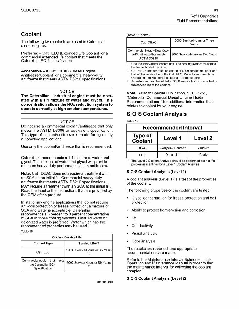
CoolantThe following two coolants are used in Caterpillardiesel engines:
Preferred – Cat ELC (Extended Life Coolant) or acommercial extended life coolant that meets theCaterpillar EC-1 specification
Acceptable – A Cat DEAC (Diesel EngineAntifreeze/Coolant) or a commercial heavy-dutyantifreeze that meets ASTM D6210 specifications
NOTICEThe Caterpillar industrial engine must be oper-ated with a 1:1 mixture of water and glycol. Thisconcentration allows the NOx reduction system tooperate correctly at high ambient temperatures.
NOTICEDo not use a commercial coolant/antifreeze that onlymeets the ASTM D3306 or equivalent specification.This type of coolant/antifreeze is made for light dutyautomotive applications.
Use only the coolant/antifreeze that is recommended.
Caterpillar recommends a 1:1 mixture of water andglycol. This mixture of water and glycol will provideoptimum heavy-duty performance as an antifreeze.
Note:Cat DEAC does not require a treatment withan SCA at the initial fill. Commercial heavy-dutyantifreeze that meets ASTM D6210 specificationsMAY require a treatment with an SCA at the initial fill.Read the label or the instructions that are provided bythe OEM of the product.
In stationary engine applications that do not requireanti-boil protection or freeze protection, a mixture ofSCA and water is acceptable. Caterpillarrecommends a 6 percent to 8 percent concentrationof SCA in those cooling systems. Distilled water ordeionized water is preferred.Water which has therecommended properties may be used.Table 16
Coolant Service Life
Coolant Type Service Life (1)
Cat ELC12000 Service Hours or Six Years
(2)
Commercial coolant that meetsthe Caterpillar EC-1
Specification
6000 Service Hours or Six Years(3)
(continued)
(Table 16, contd)
Cat DEAC 3000 Service Hours or ThreeYears
Commercial Heavy-Duty Cool-ant/Antifreeze that meets
ASTM D62103000 Service Hours or Two Years
(1) Use the interval that occurs first. The cooling systemmust alsobe flushed out at this time.
(2) Cat ELC Extender must be added at 6000 service hours or onehalf of the service life of the Cat ELC. Refer to your machineOperation and MaintenanceManual for exceptions.
(3) An extender must be added at 3000 service hours or one half ofthe service life of the coolant.
Note: Refer to Special Publication, SEBU6251,“Caterpillar Commercial Diesel Engine FluidsRecommendations ” for additional information thatrelates to coolant for your engine.
S·O·S Coolant AnalysisTable 17
Recommended IntervalType ofCoolant Level 1 Level 2
DEAC Every 250 Hours (1) Yearly(1)
ELC Optional (1) Yearly
(1) The Level 2 Coolant Analysis should be performed sooner if aproblem is identified by a Level 1 Coolant Analysis.
S·O·S Coolant Analysis (Level 1)
A coolant analysis (Level 1) is a test of the propertiesof the coolant.
The following properties of the coolant are tested:
• Glycol concentration for freeze protection and boilprotection
• Ability to protect from erosion and corrosion
• pH
• Conductivity
• Visual analysis
• Odor analysis
The results are reported, and appropriaterecommendations are made.
Refer to the Maintenance Interval Schedule in thisOperation and Maintenance Manual in order to findthe maintenance interval for collecting the coolantsamples.
S·O·S Coolant Analysis (Level 2)
SEBU8733 81Refill Capacities
Fluid Recommendations
A coolant analysis (Level 2) is a comprehensivechemical evaluation of the coolant. This analysis isalso a check of the overall condition of the inside ofthe cooling system.
The S·O·S Coolant Analysis has the followingfeatures:
• Full coolant analysis (Level 1)
• Identification of the source of metal corrosion andof contaminants
• Water hardness
• Identification of buildup of the impurities that causecorrosion
• Identification of buildup of the impurities that causescaling
The results are reported, and appropriaterecommendations are made.
Refer to the Maintenance Interval Schedule in thisOperation and Maintenance Manual, “CoolingSystem Coolant Sample (Level 2) - Obtain” for themaintenance interval for collecting the coolantsamples.
Testing the engine coolant is important to ensure thatthe engine is protected from internal cavitation andfrom corrosion. The analysis also tests the ability ofthe coolant to protect the engine from boiling andfrom freezing. The S·O·S Coolant Analysis can bedone at your Caterpillar dealer. Caterpillar S·O·SCoolant Analysis is the best way to monitor thecondition of your coolant and your cooling system.S·O·S Coolant Analysis is a program that is based onperiodic samples.
Refer to Special Publication, SEBU6251, CaterpillarCommercial Diesel Engine Fluids Recommendationsfor additional information.
82 SEBU8733Refill CapacitiesFluid Recommendations

MaintenanceRecommendations
i03648938
System Pressure ReleaseSMCS Code: 1250; 1300; 1350; 5050
Coolant System
Pressurized system: Hot coolant can cause seri-ous burn. To open cap, stop engine, wait until ra-diator is cool. Then loosen cap slowly to relievethe pressure.
The engine can have the ability to auto start. Ensurethat the power supply is isolated before any service orrepair is performed.
To relieve the pressure from the coolant system, turnoff the engine. Allow the cooling system pressure capto cool. Remove the cooling system pressure capslowly in order to relieve pressure.
Fuel SystemTo relieve the pressure from the fuel system, turn offthe engine.
High Pressure Fuel Lines
Contact with high pressure fuel may cause fluidpenetration and burn hazards. High pressure fuelspray may cause a fire hazard. Failure to followthese inspection, maintenance and service in-structionsmay cause personal injury or death.
The high pressure fuel lines are the fuel lines that arebetween the high pressure fuel pump and the highpressure fuel manifold and the fuel lines that arebetween the fuel manifold and cylinder head. Thesefuel lines are different from fuel lines on other fuelsystems.
This is because of the following differences:
• The high pressure fuel lines are constantlycharged with high pressure.
• The internal pressures of the high pressure fuellines are higher than other types of fuel system.
Before any service or repair is performed on theengine fuel lines, perform the following tasks:
1. Stop the engine.
2.Wait for 10 minutes.
Do not loosen the high pressure fuel lines in order toremove air from the fuel system.
Engine OilTo relieve pressure from the lubricating system, turnoff the engine.
i05354374
Welding on Engines withElectronic ControlsSMCS Code: 1000
NOTICEBecause the strength of the frame may decrease,some manufacturers do not recommend welding ontoa chassis frame or rail. Consult the OEM of the equip-ment or your Caterpillar dealer regarding welding ona chassis frame or rail.
Proper welding procedures are necessary in order toavoid damage to the engines ECM, sensors, andassociated components. When possible, remove thecomponent from the unit and then weld thecomponent. If removal of the component is notpossible, the following procedure must be followedwhen you weld on a unit equipped with an ElectronicEngine. The following procedure is considered to bethe safest procedure to weld on a component. Thisprocedure should provide a minimum risk of damageto electronic components.
NOTICEDo not ground the welder to electrical componentssuch as the ECM or sensors. Improper grounding cancause damage to the drive train bearings, hydrauliccomponents, electrical components, and othercomponents.
Clamp the ground cable from the welder to the com-ponent that will be welded. Place the clamp as closeas possible to the weld. This will help reduce the pos-sibility of damage.
Note: Perform the welding in areas that are free fromexplosive hazards.
1. Stop the engine. Turn the switched power to theOFF position.
2. Ensure that the fuel supply to the engine is turnedoff.
SEBU8733 83Maintenance Recommendations
System Pressure Release

3. Disconnect the negative battery cable from thebattery. If a battery disconnect switch is provided,open the switch.
4. Disconnect all electronic components from thewiring harnesses. Include the followingcomponents:
• Electronic components for the driven equipment
• ECM
• Sensors
• Electronically controlled valves
• Relays
• Electric fuel pump
• Aftertreatment ID module
NOTICEDo not use electrical components (ECM or ECM sen-sors) or electronic component grounding points forgrounding the welder.
Illustration 59 g01075639
Use the example above. The current flow from thewelder to the ground clamp of the welder will notdamage any associated components.(1) Engine(2) Welding electrode(3) Keyswitch in the OFF position(4) Battery disconnect switch in the open position(5) Disconnected battery cables(6) Battery(7) Electrical/Electronic component(8) Minimum distance between the component that is being welded
and any electrical/electronic component(9) The component that is being welded(10) Current path of the welder(11) Ground clamp for the welder
5. Connect the welding ground cable directly to thepart that will be welded. Place the ground cable asclose as possible to the weld in order to reduce thepossibility of welding current damage to thefollowing components. Bearings, hydrauliccomponents, electrical components, and groundstraps.
Note: If electrical/electronic components are used asa ground for the welder, or electrical/electroniccomponents are located between the welder groundand the weld, current flow from the welder couldseverely damage the component.
6. Protect the wiring harness from welding debris andspatter.
84 SEBU8733Maintenance RecommendationsWelding on Engines with Electronic Controls

7. Use standard welding practices to weld thematerials.
i04807435
Severe Service ApplicationSMCS Code: 1000
An engine which operates outside of normalconditions is operating in a severe serviceapplication.
An engine that operates in a severe serviceapplication may need more frequent maintenanceintervals in order to maximize the followingconditions:
• Reliability
• Service life
The number of individual applications cause theimpossibility of identifying all of the factors which maycontribute to severe service operation. Consult yourCaterpillar dealer for the unique maintenance thatmay be necessary for your engine.
An application is a severe service application if any ofthe following conditions apply:
Severe Environmental Factors• Frequent operation in dirty air
• Frequent operation at an altitude which is above1525 m (5000 ft)
• Frequent operation in ambient temperatures whichare above 32° C (90° F)
• Frequent operation in ambient temperatures whichare below 0° C (32° F)
Severe Operating Conditions• Frequent operation with inlet air which has a
corrosive content
• Operation with inlet air which has a combustiblecontent
• Operation which is outside of the intendedapplication
• Operation with a plugged fuel filter
• Extended operation at low idle (more than 20% ofhours)
• Frequent cold starts at temperatures below 0° C(32° F)
• Frequent dry starts (starting after more than 72hours of shutdown)
• Frequent hot shutdowns (shutting down the enginewithout the minimum of 2 minutes to 5 minutes ofcool down time)
• Operation above the engine rated speed
• Operation below the peak torque speed
• Operating with fuel which does not meet thestandards for distillate diesel fuel as stated inSpecial Publication, SEBU6250, CaterpillarMachine Fluids Recommendations, “DistillateDiesel Fuel”
• Operating with a blend of distillate fuel whichcontains more than 20 percent biodiesel
SEBU8733 85Maintenance Recommendations
Severe Service Application

Improper MaintenanceProcedures(MaintenanceProceduresWhichMay Contribute to a Severe ServiceApplication)• Inadequate maintenance of fuel storage tanks from
causes such as excessive water, sediment, andmicroorganism growth.
• Extending maintenance intervals beyond therecommended intervals
• Using fluids which are not recommended inSpecial Publication, SEBU6250, CaterpillarMachine Fluids Recommendations
• Extending maintenance intervals for changing theengine oil and engine coolant without S·O·Svalidation
• Extending maintenance intervals for changing airfilters, oil filters, and fuel filters
• Failure to use a water separator
• Using filters which are not recommended bySpecial Publication, PEWJ0074, 2008 Cat Filterand Fluid Application Guide
• Storing the engine for more than 3 months but lessthan 1 yr (For information about engine storage,refer to Special Publication, SEHS9031, StorageProcedure for Caterpillar Products)
86 SEBU8733Maintenance RecommendationsSevere Service Application
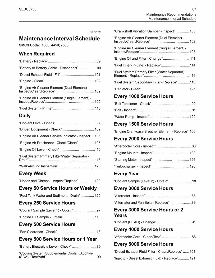
i05354411
Maintenance Interval ScheduleSMCS Code: 1000; 4450; 7500
When Required“Battery - Replace”...................................................89
“Battery or Battery Cable - Disconnect”...................90
“Diesel Exhaust Fluid - Fill”................................... 101
“Engine - Clean”.................................................... 102
“Engine Air Cleaner Element (Dual Element) -Inspect/Clean/Replace” ........................................102
“Engine Air Cleaner Element (Single Element) -Inspect/Replace”................................................... 105
“Fuel System - Prime”............................................115
Daily“Coolant Level - Check”...........................................97
“Driven Equipment - Check” ................................. 102
“Engine Air Cleaner Service Indicator - Inspect” .. 105
“Engine Air Precleaner - Check/Clean” ................ 106
“Engine Oil Level - Check”.....................................110
“Fuel System Primary Filter/Water Separator -Drain” .....................................................................118
“Walk-Around Inspection”..................................... 128
Every Week“Hoses and Clamps - Inspect/Replace”................ 120
Every 50 Service Hours or Weekly“Fuel Tank Water and Sediment - Drain” .............. 120
Every 250 Service Hours“Coolant Sample (Level 1) - Obtain”........................97
“Engine Oil Sample - Obtain”.................................110
Every 500 Service Hours“Fan Clearance - Check” .......................................113
Every 500 Service Hours or 1 Year“Battery Electrolyte Level - Check” ..........................89
“Cooling System Supplemental Coolant Additive(SCA) - Test/Add”.....................................................99
“Crankshaft Vibration Damper - Inspect”.............. 100
“Engine Air Cleaner Element (Dual Element) -Inspect/Clean/Replace” ........................................ 102
“Engine Air Cleaner Element (Single Element) -Inspect/Replace”................................................... 105
“Engine Oil and Filter - Change”............................111
“Fuel Filter (In-Line) - Replace”..............................114
“Fuel System Primary Filter (Water Separator)Element - Replace”................................................116
“Fuel System Secondary Filter - Replace” ............118
“Radiator - Clean” ................................................. 125
Every 1000 Service Hours“Belt Tensioner - Check” ..........................................90
“Belt - Inspect”..........................................................91
“Water Pump - Inspect”.........................................129
Every 1500 Service Hours“Engine Crankcase Breather Element - Replace” 106
Every 2000 Service Hours“Aftercooler Core - Inspect” .....................................88
“Engine Mounts - Inspect” ....................................109
“Starting Motor - Inspect” ...................................... 126
“Turbocharger - Inspect” .......................................126
Every Year“Coolant Sample (Level 2) - Obtain”........................98
Every 3000 Service Hours“Alternator - Inspect” ................................................88
“Alternator and Fan Belts - Replace” .......................89
Every 3000 Service Hours or 2Years“Coolant (DEAC) - Change”.....................................91
Every 4000 Service Hours“Aftercooler Core - Clean/Test”................................88
Every 5000 Service Hours“Diesel Exhaust Fluid Filter - Clean/Replace” ...... 101
“Injector (Diesel Exhaust Fluid) - Replace”........... 121
SEBU8733 87Maintenance RecommendationsMaintenance Interval Schedule

Every 6000 Service Hours or 3Years“Coolant Extender (ELC) - Add” ..............................96
Every 12 000 Service Hours or 6Years“Coolant (ELC) - Change”........................................94
Overhaul“Overhaul Considerations” ................................... 123
i01807350
Aftercooler Core - Clean/Test(Air-To-Air Aftercooler)SMCS Code: 1064-070; 1064-081
The air-to-air aftercooler is OEM installed in manyapplications. Please refer to the OEM specificationsfor information that is related to the aftercooler.
i04380914
Aftercooler Core - InspectSMCS Code: 1064-040
Note: Adjust the frequency of cleaning according tothe effects of the operating environment.
Inspect the aftercooler for these items: damaged fins,corrosion, dirt, grease, insects, leaves, oil and otherdebris. Clean the aftercooler, if necessary.
For air-to-air aftercoolers, use the same methods thatare used for cleaning radiators.
Personal injury can result from air pressure.
Personal injury can result without following prop-er procedure. When using pressure air, wear aprotective face shield and protective clothing.
Maximum air pressure at the nozzle must be lessthan 205 kPa (30 psi) for cleaning purposes.
Pressurized air is the preferredmethod for removingloose debris. Direct the air in the opposite direction ofthe fans air flow. Hold the nozzle approximately 6 mm(.25 inch) away from the fins. Slowly move the airnozzle in a direction that is parallel with the tubes.The pressurized air will remove debris that is betweenthe tubes.
Pressurized water may also be used for cleaning. Themaximum water pressure for cleaning purposes mustbe less than 275 kPa (40 psi). Use pressurized waterin order to soften mud. Clean the core from bothsides.
Use a degreaser and steam for removal of oil andgrease. Clean both sides of the core. Wash the corewith detergent and hot water. Thoroughly rinse thecore with clean water.
After cleaning, start the engine and accelerate theengine to high idle rpm. This will help in the removalof debris and drying of the core. Stop the engine. Usea light bulb behind the core in order to inspect thecore for cleanliness. Repeat the cleaning, ifnecessary.
Inspect the fins for damage. Bent fins may be openedwith a “comb”.
Note: If parts of the aftercooler system are repairedor replaced, a leak test is highly recommended. Formore information, refer to OEM specification for theaftercooler.
Inspect these items for good condition: welds,mounting brackets, air lines, connections, clamps andseals. Make repairs, if necessary.
i03641972
Alternator - InspectSMCS Code: 1405-040
Caterpillar recommends a scheduled inspection ofthe alternator. Inspect the alternator for looseconnections and proper battery charging. Inspect theammeter (if equipped) during engine operation inorder to ensure proper battery performance and/orproper performance of the electrical system. Makerepairs, as required.
Check the alternator and the battery charger forproper operation. If the batteries are properlycharged, the ammeter reading should be very nearzero. All batteries should be kept charged. Thebatteries should be kept warm because temperatureaffects the cranking power of the battery. If the batteryis too cold, the battery will not crank the engine.
When the engine is not run for long periods of time orif the engine is run for short periods, the batteries maynot fully charge. A battery with a low charge willfreeze more easily than a battery with a full charge.
88 SEBU8733Maintenance RecommendationsAftercooler Core - Clean/Test

i02320208
Alternator and Fan Belts -ReplaceSMCS Code: 1357-510
Refer to Disassembly and Assembly Manual,“Alternator Belt - Remove and Install”.
i05425759
Battery - ReplaceSMCS Code: 1401-510
Batteries give off combustible gases which canexplode. A spark can cause the combustiblegases to ignite. This can result in severe personalinjury or death.
Ensure proper ventilation for batteries that are inan enclosure. Follow the proper procedures in or-der to help prevent electrical arcs and/or sparksnear batteries. Do not smoke when batteries areserviced.
The battery cables or the batteries should not beremoved with the battery cover in place. The bat-tery cover should be removed before any servic-ing is attempted.
Removing the battery cables or the batteries withthe cover in place may cause a battery explosionresulting in personal injury.
1. Switch the engine to the OFF position. Remove allelectrical loads.
Note: After the engine has stopped, allow 2 minutesin order for the diesel exhaust fluid lines to be purgedbefore disconnecting the power.
2. Turn off any battery chargers. Disconnect anybattery chargers.
3. Ensure that the battery disconnect switch is in theOFF position.
4. Disconnect the NEGATIVE “-” cable from theNEGATIVE “-” battery terminal.
5. Disconnect the POSITIVE “+” cable from thePOSITIVE “+” battery terminal.
Note: Always recycle a battery. Never discard abattery. Dispose of used batteries to an appropriaterecycling facility.6. Remove the used battery.
7. Install the new battery.
Note: Before the cables are connected, ensure thatthe battery disconnect switch is in the OFF position.8. Connect the POSITIVE “+” cable to the POSITIVE
“+” battery terminal.
9. Connect the NEGATIVE “-” cable to theNEGATIVE “-” battery terminal.
10. Turn the battery disconnect switch to the ONposition.
i02724529
Battery Electrolyte Level -CheckSMCS Code: 1401-535-FLV
When the engine is not run for long periods of time orwhen the engine is run for short periods, the batteriesmay not fully recharge. Ensure a full charge in orderto help prevent the battery from freezing. If batteriesare properly charged, ammeter reading should bevery near zero,when the engine is in operation.
All lead-acid batteries contain sulfuric acid whichcan burn the skin and clothing. Always wear aface shield and protective clothing when workingon or near batteries.
1. Remove the filler caps. Maintain the electrolytelevel to the “FULL” mark on the battery.
If the addition of water is necessary, use distilledwater. If distilled water is not available use cleanwater that is low in minerals. Do not use artificiallysoftened water.
2. Check the condition of the electrolyte with the245-5829Coolant Battery Tester Refractometer.
3. Keep the batteries clean.
Clean the battery case with one of the followingcleaning solutions:
• Use a solution of 0.1 kg (0.2 lb) baking sodaand 1 L (1 qt) of clean water.
• Use a solution of ammonium hydroxide .
SEBU8733 89Maintenance Recommendations
Alternator and Fan Belts - Replace

Thoroughly rinse the battery case with clean water.
Use a fine grade of sandpaper to clean theterminals and the cable clamps. Clean the itemsuntil the surfaces are bright or shiny. DO NOTremove material excessively. Excessive removal ofmaterial can cause the clamps to not fit properly.Coat the clamps and the terminals with 5N-5561Silicone Lubricant, petroleum jelly or MPGM.
i05424317
Battery or Battery Cable -DisconnectSMCS Code: 1401; 1402-029
The battery cables or the batteries should not beremoved with the battery cover in place. The bat-tery cover should be removed before any servic-ing is attempted.
Removing the battery cables or the batteries withthe cover in place may cause a battery explosionresulting in personal injury.
1. Turn the start switch to the OFF position. Turn theignition switch (if equipped) to the OFF positionand remove the key and all electrical loads.
Note: After the engine has stopped, allow 2 minutesin order for the diesel exhaust fluid lines to be purgedbefore disconnecting the power.
2. Disconnect the negative battery terminal. Ensurethat the cable cannot contact the terminal. Whenfour 12 V batteries are involved, 2 negativeconnections must be disconnected.
3. Remove the positive connection.
4. Clean all disconnected connection and batteryterminals.
5. Use a fine grade of sandpaper to clean theterminals and the cable clamps. Clean the itemsuntil the surfaces are bright or shiny. DO NOTremove material excessively. Excessive removal ofmaterial can cause the clamps to fit incorrectly.Coat the clamps and the terminals with a suitablesilicone lubricant or petroleum jelly.
6. Tape the cable connections in order to help preventaccidental starting.
7. Proceed with necessary system repairs.
8. In order to connect the battery, connect the positiveconnection before the negative connector.
i04907925
Belt Tensioner - CheckSMCS Code: 1358-535
Illustration 60 g03074016
Typical example
Remove the belt. Refer to Disassembly andAssembly, “Alternator Belt - Remove and Install”.
Ensure that the belt tensioner is securely installed.Visually inspect the belt tensioner (1) for damage.Check that the pulley on the tensioner rotates freelyand that the bearing is not loose. Some engines havean idler pulley (2). Ensure that the idler pulley issecurely installed. Visually inspect the idler pulley fordamage. Ensure that the idler pulley can rotate freelyand that the bearing is not loose. If necessary,replace damaged components.
Install the belt. Refer to Disassembly and Assembly,“Alternator Belt - Remove and Install”.
90 SEBU8733Maintenance RecommendationsBattery or Battery Cable - Disconnect

i04907868
Belt - InspectSMCS Code: 1357-040; 1357; 1397-040; 1397
Illustration 61 g03073936
Typical example
To maximize the engine performance, inspect the belt(1) for wear and for cracking. Replace the belt if thebelt is worn or damaged.
• Inspect the belt for cracks, splits, glazing, grease,displacement of the cord and evidence of fluidcontamination.
The belt must be replaced if the following conditionsare present.
• The belt has a crack in more than one rib.
• More than one section of the belt is displaced inone rib of a maximum length of 50.8 mm (2 inch).
To replace the belt, refer to Disassembly andAssembly, “Alternator Belt - Remove and Install”. Ifnecessary, replace the belt tensioner. Refer toDisassembly and Assembly, “Alternator Belt -Remove and Install” for the correct procedure.
i05425761
Coolant (DEAC) - ChangeSMCS Code: 1350-070; 1395-044
Clean the cooling system and flush the coolingsystem before the recommended maintenanceinterval if the following conditions exist:
• The engine overheats frequently.
• Foaming is observed.
• The oil has entered the cooling system and thecoolant is contaminated.
• The fuel has entered the cooling system and thecoolant is contaminated.
NOTICEUse of commercially available cooling systemcleaners may cause damage to cooling system com-ponents. Use only cooling system cleaners that areapproved for Caterpillar engines.
NOTICEWhen any servicing or repair of the engine coolingsystem is performed, the procedure must be per-formed with the engine on level ground. Level groundwill allow you to check accurately the coolant level.This procedure will also help in avoiding the risk of in-troducing an air lock into the coolant system.
Note: Inspect the water pump and the watertemperature regulator after the cooling system hasbeen drained. This inspection is a good opportunity toreplace the water pump, the water temperatureregulator, and the hoses, if necessary.
Drain
Pressurized System: Hot coolant can cause seri-ous burns. To open the cooling system filler cap,stop the engine and wait until the cooling systemcomponents are cool. Loosen the cooling systempressure cap slowly in order to relieve thepressure.
1. Stop the engine and allow the engine to cool.Loosen the cooling system filler cap slowly in orderto relieve any pressure. Remove the coolingsystem filler cap.
Note: Refer to Operation and Maintenance Manual,“General Hazard Information” for information onContaining Fluid Spillage.
SEBU8733 91Maintenance Recommendations
Belt - Inspect

Illustration 62 g03075756
Illustration 63 g02350785
2. Remove connection hose (1) on the engine. Alsoremove the drain plug (2). Open the drain cock orremove the drain plug on the radiator.
Allow the coolant to drain into a suitable container.
3. Properly dispose of the drained material. Obeylocal regulations for the disposal of the material.
NOTICEDispose of used engine coolant properly or recycle.Various methods have been proposed to reclaim usedcoolant for reuse in engine cooling systems. The fulldistillation procedure is the only method acceptableby Caterpillar to reclaim the used coolant.
Alternative Drain Plug
The cylinder coolant can be drained from the plugbelow the oil cooler. Refer to illustration 64 . If thealternative drain plug (3) is removed, the O ring sealmust be replaced. Tighten the drain plug to a torqueof 35 N·m (25 lb ft).
Illustration 64 g03081697
Flush1. Flush the cooling system with clean water in order
to remove any debris.
2. Install connection hose. Clean the drain plugs.Install the drain plugs and tighten securely.
NOTICEDo not fill the cooling system faster than 5 L(1.3 US gal) per minute to avoid air locks.
Cooling system air locks may result in enginedamage.
3. Fill the cooling system with a mixture of clean waterand Caterpillar Fast Acting Cooling SystemCleaner. Add 0.5 L (1 pt) of cleaner per 15 L(4 US gal) of the cooling system capacity. Installthe cooling system filler cap.
92 SEBU8733Maintenance RecommendationsCoolant (DEAC) - Change

4. Start and run the engine at low idle for a minimumof 30 minutes. The coolant temperature should beat least 82 °C (180 °F).
NOTICEImproper or incomplete rinsing of the cooling systemcan result in damage to copper and other metalcomponents.
To avoid damage to the cooling system, make sure tocompletely flush the cooling system with clear water.Continue to flush the system until all signs of thecleaning agent are gone.
5. Stop the engine and allow the engine to cool.Loosen the cooling system filler cap slowly in orderto relieve any pressure. Remove the coolingsystem filler cap. Remove the connection hose orremove the cooling system drain plugs. Allow thewater to drain. Flush the cooling system with cleanwater. Install the connection hose.
6. The drain plug O rings on the engine block must bereplaced. Clean the drain plugs and install new Oring seal. Install the drain plugs and tighten to atorque of 35 N·m (25 lb ft).
Cooling Systems with HeavyDeposits or PluggingNote: For the following procedure to be effective,there must be some active flow through the coolingsystem components.
1. Flush the cooling system with clean water in orderto remove any debris.
2. Install the connection hose. Clean the drain plugs.Install the drain plugs and tighten securely.
NOTICEDo not fill the cooling system faster than 5 L(1.3 US gal) per minute to avoid air locks.
Cooling system air locks may result in enginedamage.
3. Fill the cooling system with a mixture of clean waterand Caterpillar Fast Acting Cooling SystemCleaner. Add 0.5 L (1 pt) of cleaner per3.8 to 7.6 L (1 to 2 US gal) of the cooling systemcapacity. Install the cooling system filler cap.
4. Start and run the engine at low idle for a minimumof 90 minutes. The coolant temperature should beat least 82 °C (180 °F).
NOTICEImproper or incomplete rinsing of the cooling systemcan result in damage to copper and other metalcomponents.
To avoid damage to the cooling system, make sure tocompletely flush the cooling system with clear water.Continue to flush the system until all signs of thecleaning agent are gone.
5. Stop the engine and allow the engine to cool.Loosen the cooling system filler cap slowly in orderto relieve any pressure. Remove the coolingsystem filler cap. Open the drain valve (ifequipped) or remove the cooling system drainplugs. Allow the water to drain. Flush the coolingsystem with clean water. Install the connectionhose.
6. The drain plug O rings on the engine block must bereplaced. Clean the drain plugs and install new Oring seal. Install the drain plugs and tighten to atorque of 35 N·m (25 lb ft).
Fill
NOTICEDo not fill the cooling system faster than 5 L(1.3 US gal) per minute to avoid air locks.
Cooling system air locks may result in enginedamage.
1. Fill the cooling system with the coolant/antifreeze.Refer to this Operation and Maintenance Manual,“Refill Capacities and Recommendations” topic(Maintenance Section) for more information oncooling system specifications. Do not install thecooling system filler cap.
2. Start and run the engine at low idle. Increase theengine rpm to high idle. Operate the engine inorder to open the engine thermostat. Thisoperation will allow any air in the system to bepurged. Decrease the engine speed to low idle.Stop the engine.
3.Maintain the coolant level at the maximummarkthat is correct for your application.
SEBU8733 93Maintenance Recommendations
Coolant (DEAC) - Change

4. Clean the cooling system filler cap. Inspect thegasket that is on the cooling system filler cap. If thegasket that is on the cooling system filler cap isdamaged, discard the old cooling system filler capand install a new cooling system filler cap. If thegasket that is on the cooling system filler cap is notdamaged, perform a pressure test. A 9S-8140Pressurizing Pump is used to perform the pressuretest. The correct pressure for the cooling systemfiller cap is stamped on the face of the coolingsystem filler cap. If the cooling system filler capdoes not retain the correct pressure, install a newcooling system filler cap.
5. Start the engine. Inspect the cooling system forleaks and for the correct operating temperature.
i05360509
Coolant (ELC) - ChangeSMCS Code: 1350-070; 1395-044
Clean the cooling system and flush the coolingsystem before the recommended maintenanceinterval if the following conditions exist:
• The engine overheats frequently.
• Foaming is observed.
• The oil has entered the cooling system and thecoolant is contaminated.
• The fuel has entered the cooling system and thecoolant is contaminated.
Note:When the cooling system is cleaned, onlyclean water is needed when the ELC is drained andreplaced.
Note: Inspect the water pump and the watertemperature regulator after the cooling system hasbeen drained. Replace the water pump, the watertemperature regulator, and the hoses, if necessary.
NOTICEService or repair of the engine cooling system mustbe performed on level ground. The engine must belevel in order to check the coolant level. The enginemust be level in order to avoid the risk of introducingan air lock into the coolant system.
Drain
Pressurized System: Hot coolant can cause seri-ous burns. To open the cooling system filler cap,stop the engine and wait until the cooling systemcomponents are cool. Loosen the cooling systempressure cap slowly in order to relieve thepressure.
1. Stop the engine and allow the engine to cool.Loosen the cooling system filler cap slowly in orderto relieve any pressure. Remove the coolingsystem filler cap.
94 SEBU8733Maintenance RecommendationsCoolant (ELC) - Change

Illustration 65 g03075756
Illustration 66 g02350785
2. Remove connection hose (1) on the engine. Alsoremove the drain plug (2). Open the drain cock orremove the drain plug on the radiator.
Allow the coolant to drain.
NOTICEDispose of used engine coolant properly or recycle.Various methods have been proposed to reclaim usedcoolant for reuse in engine cooling systems. The fulldistillation procedure is the only method acceptableby Caterpillar to reclaim the used coolant.
For information regarding the disposal and therecycling of used coolant, consult your Caterpillardealer or consult Dealer Service Tools .
Flush1. Flush the cooling system with clean water in order
to remove any debris.
2. Install the connection hose. Clean the drain plugs.Install the drain plugs. Refer to TorqueSpecifications, SENR3130 for more information onthe correct torques.
NOTICEDo not fill the cooling system faster than 5 L(1.3 US gal) per minute to avoid air locks.
Cooling system air locks may result in enginedamage.
3. Fill the cooling system with clean water. Install thecooling system filler cap.
4. Start and run the engine at low idle until thetemperature reaches 49 to 66 °C (120 to 150 °F).
5. Stop the engine and allow the engine to cool.Loosen the cooling system filler cap slowly in orderto relieve any pressure. Remove the coolingsystem filler cap. Remove the connection hoseand remove the cooling system drain plugs. Allowthe water to drain. Flush the cooling system withclean water. Install the connection hose. Clean thedrain plugs. Install the drain plugs. Refer to TorqueSpecifications, SENR3130 for more information onthe correct torques.
Fill
NOTICEDo not fill the cooling system faster than 5 L(1.3 US gal) per minute to avoid air locks.
Cooling system air locks may result in enginedamage.
1. Fill the cooling system with Extended Life Coolant(ELC). Refer to this Operation and MaintenanceManual, “Refill Capacities and Recommendations”topic (Maintenance Section) for more informationon cooling system specifications. Do not install thecooling system filler cap.
SEBU8733 95Maintenance Recommendations
Coolant (ELC) - Change

2. Start and run the engine at low idle. Increase theengine rpm to high idle. Operate the engine inorder to open the engine thermostat. An openthermostat will allow any air in the system to bepurged. Decrease the engine speed to low idle.Stop the engine.
3.Maintain the coolant level at the maximummarkthat is correct for your application.
4. Clean the cooling system filler cap. Inspect thegasket that is on the cooling system filler cap. If thegasket that is on the cooling system filler cap isdamaged, discard the old cooling system filler capand install a new cooling system filler cap. If thegasket that is on the cooling system filler cap is notdamaged, use a 9S-8140Pressurizing Pump inorder to pressure test the cooling system filler cap.The correct pressure for the cooling system fillercap is stamped on the face of the cooling systemfiller cap. If the cooling system filler cap does notretain the correct pressure, install a new coolingsystem filler cap.
5. Start the engine. Inspect the cooling system forleaks and for proper operating temperature.
i04913503
Coolant Extender (ELC) - AddSMCS Code: 1352-544-NL
Cat ELC (Extended Life Coolant) does not requirethe frequent additions of any supplemental coolingadditives which are associated with the presentconventional coolants. The Cat ELC Extender onlyneeds adding once.
NOTICEUse only Cat Extended Life Coolant (ELC) Extenderwith Cat ELC.
Do NOT use conventional supplemental coolant addi-tive (SCA) with Cat ELC. Mixing Cat ELC with con-ventional coolants and/or conventional SCA reducesthe Cat ELC service life.
Check the cooling system only when the engine isstopped and cool.
Personal injury can result from hot coolant, steamand alkali.
At operating temperature, engine coolant is hotand under pressure. The radiator and all lines toheaters or the engine contain hot coolant orsteam. Any contact can cause severe burns.
Remove cooling system pressure cap slowly torelieve pressure only when engine is stopped andcooling system pressure cap is cool enough totouch with your bare hand.
Do not attempt to tighten hose connections whenthe coolant is hot, the hose can come off causingburns.
Cooling System Coolant Additive contains alkali.Avoid contact with skin and eyes.
NOTICECare must be taken to ensure that fluids are con-tained during performance of inspection, mainte-nance, testing, adjusting, and repair of the product.Be prepared to collect the fluid with suitable contain-ers before opening any compartment or disassem-bling any component containing fluids.
Refer to Special Publication, NENG2500, “Cat DealerService Tool Catalog” or refer to Special Publication,PECJ0003, “Cat Shop Supplies and Tools Catalog”for tools and supplies suitable to collect and containfluids on Cat products.
Dispose of all fluids according to local regulations andmandates.
NOTICEWhen any servicing or repair of the engine coolingsystem is performed, the procedure must be per-formed with the engine on level ground. This proce-dure will allow you to check accurately the coolantlevel. This procedure will also help in avoiding the riskof introducing an air lock into the coolant system.
1. Loosen the cooling system filler cap slowly in orderto relieve pressure. Remove the cooling systemfiller cap.
2. If necessary, drain enough coolant from the coolingsystem in order to add the Cat ELC Extender .
3. Add Cat ELC Extender according to therequirements for your engines cooling systemcapacity. Refer to the Operation and MaintenanceManual, “Refill Capacities and Recommendations”article for more information.
96 SEBU8733Maintenance RecommendationsCoolant Extender (ELC) - Add

4. Clean the cooling system filler cap. Inspect thegaskets on the cooling system filler cap. Replacethe cooling system filler cap if the gaskets aredamaged. Install the cooling system filler cap.
i05436397
Coolant Level - CheckSMCS Code: 1395-082
Pressurized System: Hot coolant can cause seri-ous burns. To open the cooling system filler cap,stop the engine and wait until the cooling systemcomponents are cool. Loosen the cooling systempressure cap slowly in order to relieve thepressure.
Check the coolant level when the engine is stoppedand cool.
NOTICEWhen any servicing or repair of the engine coolingsystem is performed, the procedure must be per-formed with the engine on level ground. This proce-dure will allow you to check accurately the coolantlevel. This procedure will also help in avoiding the riskof introducing an air lock into the coolant system.
1. Remove the cooling system filler cap slowly inorder to relieve pressure.
2.Maintain the coolant level at the maximummarkthat is correct for your application. If the engine isequipped with a sight glass, maintain the coolantlevel to the correct level in the sight glass.
Illustration 67 g02590196
Typical filler cap gaskets
3. Clean the cooling system filler cap and check thecondition of the filler cap gaskets. Replace thecooling system filler cap if the filler cap gaskets aredamaged. Reinstall the cooling system filler cap.
4. Inspect the cooling system for leaks.
Note: The Diesel Exhaust Fluid (DEF) tank requirescoolant flow around the tank. The Coolant DiverterValve (CDV) will turn the flow on or off. If the coolantsystem has been filled with the CDV in the closedposition, coolant level will drop because of theopening of the CDV.
i04913603
Coolant Sample (Level 1) -ObtainSMCS Code: 1350-008; 1395-008; 1395-554; 7542
Note: Obtaining a Coolant Sample (Level 1) isoptional if the cooling system is filled with CatELC (Extended Life Coolant).Cooling systemsfilled with Cat ELC should have a Coolant Sample(Level 2) that is obtained at the recommendedinterval as stated in the maintenance intervalschedule.
Note: Obtain a Coolant Sample (Level 1) if thecooling system is filled with any other coolantinstead of Cat ELC including the followingcoolants:
SEBU8733 97Maintenance Recommendations
Coolant Level - Check

• Commercial long life coolants that meet theCaterpillar Engine Coolant Specification -1(Caterpillar EC-1)
• Cat DEAC (Diesel Engine Antifreeze/Coolant)
• Commercial heavy-duty coolant/antifreezeTable 18
Recommended Interval
Type of Coolant Level 1 Level 2
Cat DEAC
Every 250 servicehours
Every year(1)
Conventional heavyduty-coolant
Commercial coolantthat meets the re-quirements of theCaterpillar EC-1
standard
Cat ELC or conven-tional EC-1 coolant
Optional Every year(1)
(1) The Level 2 Coolant Analysis should be performed sooner if aproblem is suspected or identified.
NOTICEAlways use a designated pump for oil sampling, anduse a separate designated pump for coolant sam-pling. Using the same pump for both types of samplesmay contaminate the samples that are being drawn.This contaminate may cause a false analysis and anincorrect interpretation that could lead to concerns byboth dealers and customers.
Note: Level 1 results may indicate a need forLevel 2 Analysis.
Obtain the sample of the coolant as close as possibleto the recommended sampling interval. In order toreceive the full effect of S·O·S analysis, establish aconsistent trend of data. In order to establish apertinent history of data, perform consistentsamplings that are evenly spaced. Supplies forcollecting samples can be obtained from yourCaterpillar dealer.
Use the following guidelines for proper sampling ofthe coolant:
• Complete the information on the label for thesampling bottle before you begin to take thesamples.
• Keep the unused sampling bottles stored in plasticbags.
• Obtain coolant samples directly from the coolantsample port. You should not obtain the samplesfrom any other location.
• Keep the lids on empty sampling bottles until youare ready to collect the sample.
• Place the sample in the mailing tube immediatelyafter obtaining the sample in order to avoidcontamination.
• Never collect samples from expansion bottles.
• Never collect samples from the drain for a system.
Submit the sample for Level 1 analysis.
For additional information about coolant analysis, seethis Operation and Maintenance Manual, “RefillCapacities and Recommendations” or consult yourCaterpillar dealer.
i04913805
Coolant Sample (Level 2) -ObtainSMCS Code: 1350-008; 1395-008; 1395-554; 7542
NOTICEAlways use a designated pump for oil sampling, anduse a separate designated pump for coolant sam-pling. Using the same pump for both types of samplesmay contaminate the samples that are being drawn.This contaminate may cause a false analysis and anincorrect interpretation that could lead to concerns byboth dealers and customers.
98 SEBU8733Maintenance RecommendationsCoolant Sample (Level 2) - Obtain

NOTICECare must be taken to ensure that fluids are con-tained during performance of inspection, mainte-nance, testing, adjusting and repair of the product. Beprepared to collect the fluid with suitable containersbefore opening any compartment or disassemblingany component containing fluids.
Refer to Special Publication, NENG2500, “CaterpillarDealer Service Tool Catalog” or refer to Special Publi-cation, PECJ0003, “Caterpillar Shop Supplies andTools Catalog” for tools and supplies suitable to col-lect and contain fluids on Caterpillar products.
Dispose of all fluids according to local regulations andmandates.
Refer to Operation and Maintenance Manual,“Cooling System Coolant Sample (Level 1) - Obtain”for the guidelines for proper sampling of the coolant.
Submit the sample for Level 2 analysis.
For additional information about coolant analysis, seeSpecial Publication, SEBU6251, “CaterpillarCommercial Diesel Engines FluidsRecommendations” or consult your Caterpillardealer.
i03644817
Cooling System SupplementalCoolant Additive (SCA) - Test/AddSMCS Code: 1352-045; 1395-081
Cooling system coolant additive contains alkali.To help prevent personal injury, avoid contactwith the skin and the eyes. Do not drink coolingsystem coolant additive.
Note: Test the concentration of the SupplementalCoolant Additive (SCA) or test the SCA concentrationas part of an S·O·S Coolant Analysis.
Test for SCA Concentration
Coolant and SCA
NOTICEDo not exceed the recommended six percent supple-mental coolant additive concentration.
Use the 8T-5296Coolant Conditioner Test Kit oruse the 4C-9301Coolant Conditioner Test Kit inorder to check the concentration of the SCA. Refer tothis Operation and Maintenance Manual, “RefillCapacities and Recommendations” for moreinformation.
Water and SCA
NOTICEDo not exceed the recommended eight percent sup-plemental coolant additive concentration.
Test the concentration of the SCA with the 8T-5296Coolant Conditioner Test Kit. Refer to the SpecialPublication, SEBU6251, Caterpillar CommercialDiesel Engine Fluids Recommendations for moreinformation.
S·O·S Coolant AnalysisS·O·S coolant samples can be analyzed at yourCaterpillar dealer. S·O·S Coolant Analysis is aprogram that is based on periodic samples.
Level 1Level 1 is a basic analysis of the coolant. Thefollowing items are tested:
• Glycol Concentration
• Concentration of SCA
• pH
• Conductivity
The results are reported, and recommendations aremade according to the results. Consult yourCaterpillar dealer for information on the benefits ofmanaging your equipment with an S·O·S CoolantAnalysis.
Level 2This level coolant analysis is recommended when theengine is overhauled. Refer to this Operations andMaintenance Manual, “Overhaul Considerations” forfurther information.
SEBU8733 99Maintenance Recommendations
Cooling System Supplemental Coolant Additive (SCA) - Test/Add

Add the SCA, If NecessaryNOTICE
Do not exceed the recommended amount of supple-mental coolant additive concentration. Excessive sup-plemental coolant additive concentration can formdeposits on the higher temperature surfaces of thecooling system, reducing the engine's heat transfercharacteristics. Reduced heat transfer could causecracking of the cylinder head and other high tempera-ture components. Excessive supplemental coolantadditive concentration could also result in radiatortube blockage, overheating, and/or accelerated waterpump seal wear. Never use both liquid supplementalcoolant additive and the spin-on element (if equipped)at the same time. The use of those additives togethercould result in supplemental coolant additive concen-tration exceeding the recommendedmaximum.
Pressurized System: Hot coolant can cause seri-ous burns. To open the cooling system filler cap,stop the engine and wait until the cooling systemcomponents are cool. Loosen the cooling systempressure cap slowly in order to relieve thepressure.
NOTICEWhen any servicing or repair of the engine coolingsystem is performed the procedure must be per-formed with the engine on level ground. This will allowyou to accurately check the coolant level. This will al-so help in avoiding the risk of introducing an air lockinto the coolant system.
1. Slowly loosen the cooling system filler cap in orderto relieve the pressure. Remove the coolingsystem filler cap.
Note: Always discard drained fluids according to localregulations.2. If necessary, drain some coolant from the cooling
system into a suitable container in order to allowspace for the extra SCA.
3. Add the proper amount of SCA. Refer to theSpecial Publication, SEBU6251, CaterpillarCommercial Diesel Engines FluidsRecommendations for more information on SCArequirements.
4. Clean the cooling system filler cap. Inspect thegaskets of the cooling system filler cap. If thegaskets are damaged, replace the old coolingsystem filler cap with a new cooling system fillercap. Install the cooling system filler cap.
i03634651
Crankshaft Vibration Damper -InspectSMCS Code: 1205-040
Viscous DamperThe viscous damper has a inertia weight that islocated inside a fluid filled case. The inertia weightmoves in the case in order to limit torsional vibration.
Visually inspect the crankshaft damper. Ensure thatthe cooling fins (1) on the crankshaft damper areclean and free from dirt.
Illustration 68 g01950241
Typical example
Inspect the damper and replace the damper for any ofthe following reasons:
• The damper is dented, cracked, or leaking.
For information on removal of the crankshaft damper,refer to Disassembly and Assembly, “VibrationDamper and Pulley - Remove and Install”.
100 SEBU8733Maintenance RecommendationsCrankshaft Vibration Damper - Inspect

i05413412
Diesel Exhaust Fluid - FillSMCS Code: 108K-544
Refer to the original equipment manufactureinformation for the Diesel Exhaust Fluid (DEF) tankcapacity.
Illustration 69 g03379943
Lockable type DEF Filler cap
Illustration 70 g03417998
Typical example
1. Ensure that the DEF cap (1) and the surroundingarea is clean and free from dirt.
2. Remove the DEF cap from the tank.
3. Fill the tank with the required amount of DEF.Ensure that dirt is not introduced into the tankduring filling. Do not over fill the tank. The DEFmay require room for expansion.
4. The opening on the DEF tank (2) is a specialdiameter. Ensure that the correct nozzle is usedwhen filling the DEF tank.
5. Install the DEF cap.
i04928595
Diesel Exhaust Fluid Filter -Clean/ReplaceSMCS Code: 108K-070-FI; 108K-510-FI
Illustration 71 g03097598
1. Ensure that the area around the Diesel ExhaustFluid (DEF) filter is clean and free from dirt. Use a27mm Bi-Hex socket in order to remove filter cap(3).
2. Remove the expansion device (2). Use toolsupplied with new filter element in order to removeexpansion device. Remove filter element (1) frommain body (4).
3. Install new filter element (1) into main body (4).Install expansion device (2) into filter element (1).Install filter cap (3) and tighten cap to 20 N·m(15 lb ft).
SEBU8733 101Maintenance Recommendations
Diesel Exhaust Fluid - Fill
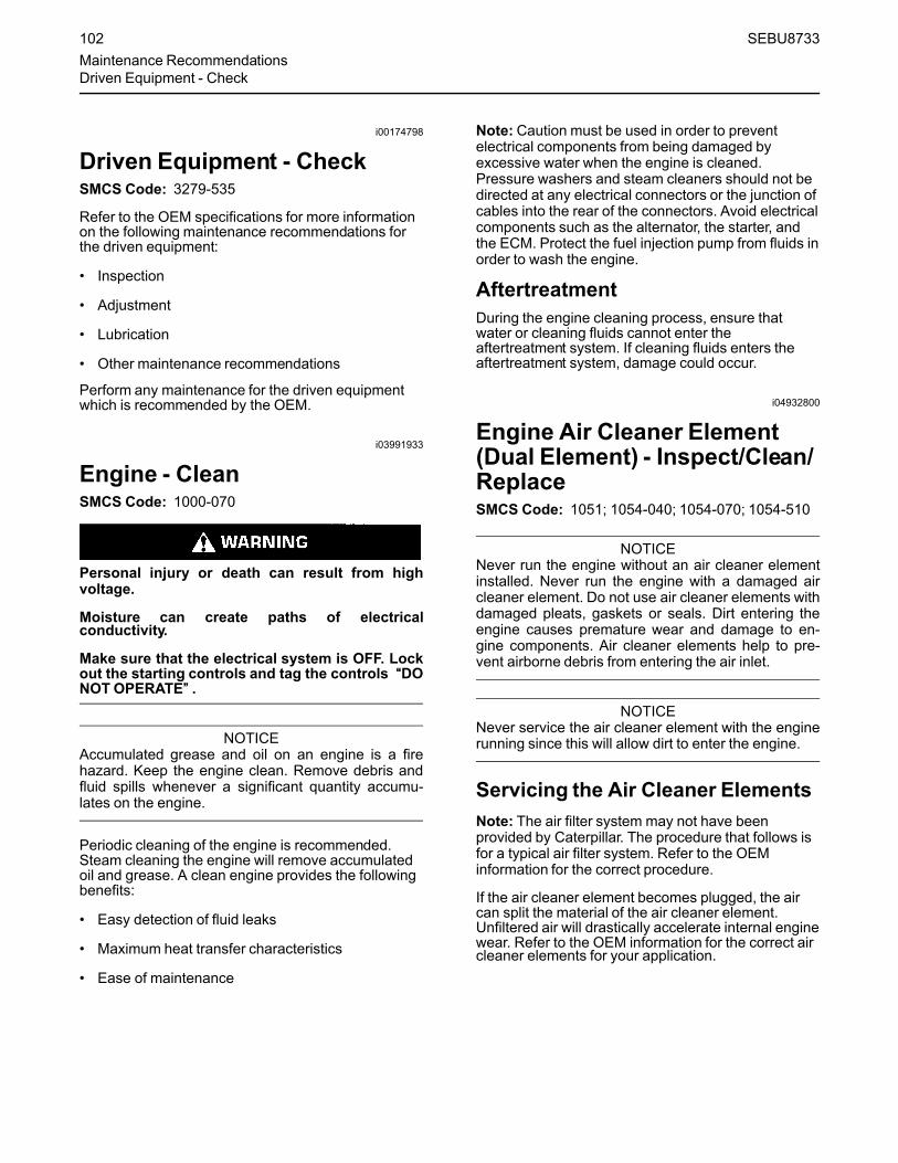
i00174798
Driven Equipment - CheckSMCS Code: 3279-535
Refer to the OEM specifications for more informationon the following maintenance recommendations forthe driven equipment:
• Inspection
• Adjustment
• Lubrication
• Other maintenance recommendations
Perform any maintenance for the driven equipmentwhich is recommended by the OEM.
i03991933
Engine - CleanSMCS Code: 1000-070
Personal injury or death can result from highvoltage.
Moisture can create paths of electricalconductivity.
Make sure that the electrical system is OFF. Lockout the starting controls and tag the controls ““DONOT OPERATE”” .
NOTICEAccumulated grease and oil on an engine is a firehazard. Keep the engine clean. Remove debris andfluid spills whenever a significant quantity accumu-lates on the engine.
Periodic cleaning of the engine is recommended.Steam cleaning the engine will remove accumulatedoil and grease. A clean engine provides the followingbenefits:
• Easy detection of fluid leaks
• Maximum heat transfer characteristics
• Ease of maintenance
Note: Caution must be used in order to preventelectrical components from being damaged byexcessive water when the engine is cleaned.Pressure washers and steam cleaners should not bedirected at any electrical connectors or the junction ofcables into the rear of the connectors. Avoid electricalcomponents such as the alternator, the starter, andthe ECM. Protect the fuel injection pump from fluids inorder to wash the engine.
AftertreatmentDuring the engine cleaning process, ensure thatwater or cleaning fluids cannot enter theaftertreatment system. If cleaning fluids enters theaftertreatment system, damage could occur.
i04932800
Engine Air Cleaner Element(Dual Element) - Inspect/Clean/ReplaceSMCS Code: 1051; 1054-040; 1054-070; 1054-510
NOTICENever run the engine without an air cleaner elementinstalled. Never run the engine with a damaged aircleaner element. Do not use air cleaner elements withdamaged pleats, gaskets or seals. Dirt entering theengine causes premature wear and damage to en-gine components. Air cleaner elements help to pre-vent airborne debris from entering the air inlet.
NOTICENever service the air cleaner element with the enginerunning since this will allow dirt to enter the engine.
Servicing the Air Cleaner ElementsNote: The air filter system may not have beenprovided by Caterpillar. The procedure that follows isfor a typical air filter system. Refer to the OEMinformation for the correct procedure.
If the air cleaner element becomes plugged, the aircan split the material of the air cleaner element.Unfiltered air will drastically accelerate internal enginewear. Refer to the OEM information for the correct aircleaner elements for your application.
102 SEBU8733Maintenance RecommendationsDriven Equipment - Check

• Check the precleaner (if equipped) and the dustbowl daily for accumulation of dirt and debris.Remove any dirt and debris, as needed.
• Operating in dirty conditions may require morefrequent service of the air cleaner element.
• The air cleaner element should be replaced atleast one time per year. This replacement shouldbe performed regardless of the number ofcleanings.
Replace the dirty air cleaner elements with clean aircleaner elements. Before installation, the air cleanerelements should be thoroughly checked for tears and/or holes in the filter material. Inspect the gasket or theseal of the air cleaner element for damage. Maintain asupply of suitable air cleaner elements forreplacement purposes.
Dual Element Air CleanersThe dual element air cleaner contains a primary aircleaner element and a secondary air cleanerelement.
The primary air cleaner element can be used up to sixtimes if the element is properly cleaned and properlyinspected. The primary air cleaner element should bereplaced at least one time per year. This replacementshould be performed regardless of the number ofcleanings.
The secondary air cleaner element is not serviceable.Refer to the OEM information for instructions in orderto replace the secondary air cleaner element.
When the engine is operating in environments thatare dusty or dirty, air cleaner elements may requiremore frequent replacement.
Illustration 72 g00736431
(1) Cover(2) Primary air cleaner element(3) Secondary air cleaner element(4) Air inlet
1. Remove the cover. Remove the primary air cleanerelement.
2. The secondary air cleaner element should beremoved and discarded for every three cleaningsof the primary air cleaner element.
Note: Refer to “Cleaning the Primary Air CleanerElements”.
3. Cover the air inlet with tape in order to keep outdirt.
4. Clean the inside of the air cleaner cover and bodywith a clean, dry cloth.
5. Remove the tape from the air inlet. Install thesecondary air cleaner element. Install a primary aircleaner element that is new or cleaned.
6. Install the air cleaner cover.
7. Reset the air cleaner service indicator.
Cleaning the Primary Air CleanerElementsRefer to the OEM information in order to determinethe number of times that the primary filter elementcan be cleaned. When the primary air cleanerelement is cleaned, check for rips or tears in the filtermaterial. The primary air cleaner element should bereplaced at least one time per year. This replacementshould be performed regardless of the number ofcleanings.
NOTICEDo not tap or strike the air cleaner element.
Do not wash the primary air cleaner element.
Use low pressure (207 kPa 30 psi maximum) pressur-ized air or vacuum cleaning to clean the primary aircleaner element.
Take extreme care in order to avoid damage to the aircleaner elements.
Do not use air cleaner elements that have damagedpleats, gaskets, or seals.
Refer to the OEM information in order to determinethe number of times that the primary air cleanerelement can be cleaned. Do not clean the primary airfilter element more than three times. The primary aircleaner element must be replaced at least one timeper year.
Cleaning the air filter element will not extend the lifeof the air filter element.
Visually inspect the primary air cleaner elementbefore cleaning. Inspect air cleaner elements fordamage to the pleats, the seals, the gaskets, and theouter cover. Discard any damaged air cleanerelement.
SEBU8733 103Maintenance Recommendations
Engine Air Cleaner Element (Dual Element) - Inspect/Clean/Replace
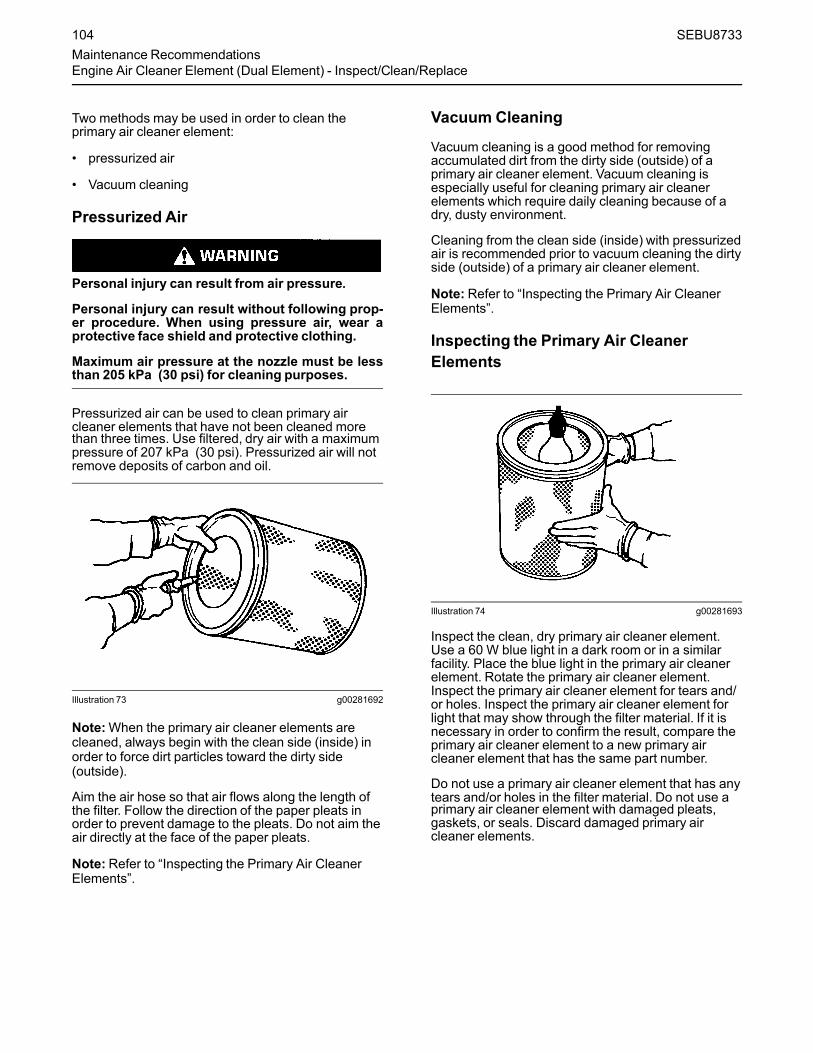
Two methods may be used in order to clean theprimary air cleaner element:
• pressurized air
• Vacuum cleaning
Pressurized Air
Personal injury can result from air pressure.
Personal injury can result without following prop-er procedure. When using pressure air, wear aprotective face shield and protective clothing.
Maximum air pressure at the nozzle must be lessthan 205 kPa (30 psi) for cleaning purposes.
Pressurized air can be used to clean primary aircleaner elements that have not been cleaned morethan three times. Use filtered, dry air with a maximumpressure of 207 kPa (30 psi). Pressurized air will notremove deposits of carbon and oil.
Illustration 73 g00281692
Note:When the primary air cleaner elements arecleaned, always begin with the clean side (inside) inorder to force dirt particles toward the dirty side(outside).
Aim the air hose so that air flows along the length ofthe filter. Follow the direction of the paper pleats inorder to prevent damage to the pleats. Do not aim theair directly at the face of the paper pleats.
Note:Refer to “Inspecting the Primary Air CleanerElements”.
Vacuum Cleaning
Vacuum cleaning is a good method for removingaccumulated dirt from the dirty side (outside) of aprimary air cleaner element. Vacuum cleaning isespecially useful for cleaning primary air cleanerelements which require daily cleaning because of adry, dusty environment.
Cleaning from the clean side (inside) with pressurizedair is recommended prior to vacuum cleaning the dirtyside (outside) of a primary air cleaner element.
Note: Refer to “Inspecting the Primary Air CleanerElements”.
Inspecting the Primary Air CleanerElements
Illustration 74 g00281693
Inspect the clean, dry primary air cleaner element.Use a 60 W blue light in a dark room or in a similarfacility. Place the blue light in the primary air cleanerelement. Rotate the primary air cleaner element.Inspect the primary air cleaner element for tears and/or holes. Inspect the primary air cleaner element forlight that may show through the filter material. If it isnecessary in order to confirm the result, compare theprimary air cleaner element to a new primary aircleaner element that has the same part number.
Do not use a primary air cleaner element that has anytears and/or holes in the filter material. Do not use aprimary air cleaner element with damaged pleats,gaskets, or seals. Discard damaged primary aircleaner elements.
104 SEBU8733Maintenance RecommendationsEngine Air Cleaner Element (Dual Element) - Inspect/Clean/Replace

i01432811
Engine Air Cleaner Element(Single Element) - Inspect/ReplaceSMCS Code: 1051; 1054-040; 1054-510
Perform the Operation and Maintenance Manual,“Engine Air Cleaner Service Indicator-Inspect”procedure and perform the Operation andMaintenance Manual, “Engine Air Precleaner Check/Clean” procedure (if equipped) before performing thefollowing procedure.
NOTICENever run the engine without an air cleaner elementinstalled. Never run the engine with a damaged aircleaner element. Do not use air cleaner elements withdamaged pleats, gaskets or seals. Dirt entering theengine causes premature wear and damage to en-gine components. Air cleaner elements help to pre-vent airborne debris from entering the air inlet.
NOTICENever service the air cleaner element with the enginerunning since this will allow dirt to enter the engine.
Illustration 75 g00310664
(1) Air cleaner cover(2) Air filter element(3) Air inlet
1. Remove air cleaner cover (1) and remove air filterelement (2).
2. Cover air inlet (3) with tape or a clean cloth so thatdebris cannot enter the air inlet.
3. Clean the inside of air cleaner cover (1). Clean thebody that holds the air cleaner element.
4. Inspect the replacement element for the followingitems:damage, dirt and debris.
5. Remove the seal from the opening of the air inlet.
6. Install a clean, undamaged air filter element (2).
7. Install air cleaner cover (1).
8. Reset the air cleaner service indicator.
i02335405
Engine Air Cleaner ServiceIndicator - InspectSMCS Code: 7452-040
Some engines may be equipped with a differentservice indicator.
Some engines are equipped with a differential gaugefor inlet air pressure. The differential gauge for inletair pressure displays the difference in the pressurethat is measured before the air cleaner element andthe pressure that is measured after the air cleanerelement. As the air cleaner element becomes dirty,the pressure differential rises. If your engine isequipped with a different type of service indicator,follow the OEM recommendations in order to servicethe air cleaner service indicator.
The service indicator may be mounted on the aircleaner element or in a remote location.
Illustration 76 g00103777
Typical service indicator
Observe the service indicator. The air cleanerelement should be cleaned or the air cleaner elementshould be replaced when one of the followingconditions occur:
• The yellow diaphragm enters the red zone.
• The red piston locks in the visible position.
Test the Service IndicatorService indicators are important instruments.
SEBU8733 105Maintenance Recommendations
Engine Air Cleaner Element (Single Element) - Inspect/Replace
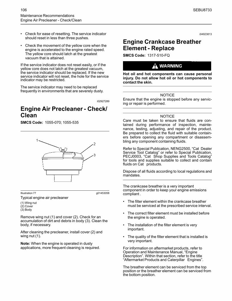
• Check for ease of resetting. The service indicatorshould reset in less than three pushes.
• Check the movement of the yellow core when theengine is accelerated to the engine rated speed.The yellow core should latch at the greatestvacuum that is attained.
If the service indicator does not reset easily, or if theyellow core does not latch at the greatest vacuum,the service indicator should be replaced. If the newservice indicator will not reset, the hole for the serviceindicator may be restricted.
The service indicator may need to be replacedfrequently in environments that are severely dusty.
i02927289
Engine Air Precleaner - Check/CleanSMCS Code: 1055-070; 1055-535
Illustration 77 g01453058
Typical engine air precleaner(1) Wing nut(2) Cover(3) Body
Remove wing nut (1) and cover (2). Check for anaccumulation of dirt and debris in body (3). Clean thebody, if necessary.
After cleaning the precleaner, install cover (2) andwing nut (1).
Note:When the engine is operated in dustyapplications, more frequent cleaning is required.
i04923813
Engine Crankcase BreatherElement - ReplaceSMCS Code: 1317-510-FQ
Hot oil and hot components can cause personalinjury. Do not allow hot oil or hot components tocontact the skin.
NOTICEEnsure that the engine is stopped before any servic-ing or repair is performed.
NOTICECare must be taken to ensure that fluids are con-tained during performance of inspection, mainte-nance, testing, adjusting, and repair of the product.Be prepared to collect the fluid with suitable contain-ers before opening any compartment or disassem-bling any component containing fluids.
Refer to Special Publication, NENG2500, “Cat DealerService Tool Catalog” or refer to Special Publication,PECJ0003, “Cat Shop Supplies and Tools Catalog”for tools and supplies suitable to collect and containfluids on Cat products.
Dispose of all fluids according to local regulations andmandates.
The crankcase breather is a very importantcomponent in order to keep your engine emissionscompliant .
• The filter element within the crankcase breathermust be serviced at the prescribed service interval.
• The correct filter element must be installed beforethe engine is operated.
• The installation of the filter element is veryimportant.
• The quality of the filter element that is installed isvery important.
For information on aftermarket products, refer toOperation and Maintenance Manual, “EngineDescription”. Within that section, refer to the title“Aftermarket Products and Caterpillar Engines”.
The breather element can be serviced from the topposition or the breather element can be serviced fromthe bottom position.
106 SEBU8733Maintenance RecommendationsEngine Air Precleaner - Check/Clean

Top Service
Illustration 78 g03090965
1. Ensure that dirt cannot enter the breatherassembly. Ensure that the outside body of thebreather assembly is clean and free from damage.Place a container under the breather assembly.
2. Rotate the top cap (1) counterclockwise into theunlocked position. Remove the top cap from thebody of the breather (3) and remove the filterelement (2).
Illustration 79 g03090963
3. Remove the old seal (4) and install a new seal.
Note: The cut away from section (5) in the top capallows access to the seal.
Illustration 80 g03090938
(A) Alignment position(B) Alignment position
SEBU8733 107Maintenance Recommendations
Engine Crankcase Breather Element - Replace

4. Install a new filter element into the breather body(3). Ensure the correct position of the element,refer to illustration 80 . Align position (A) on the topcap to position (B) on the filter element.
Illustration 81 g02346577
Typical example
5. Install the top cap (1). Rotate the top cap by handclockwise until the top cap locks into the lockedposition (C) on the breather body.
6. Remove the container.
BottomServiceEnsure that dirt cannot enter the breather assembly.
Illustration 82 g02346498
Typical example(X) Alignment mark(Y) Alignment mark
1. Ensure that the outside body of the breatherassembly is clean and free from damage. Place acontainer under the breather.
2. Remove the tube connection (1). Ensure that dirtcannot enter the tube connection. Note the positionof the alignment marks (X and Y). Rotate thebottom cap (2) counterclockwise in order torelease the cap and the filter element (4) from thebreather body (3).
108 SEBU8733Maintenance RecommendationsEngine Crankcase Breather Element - Replace
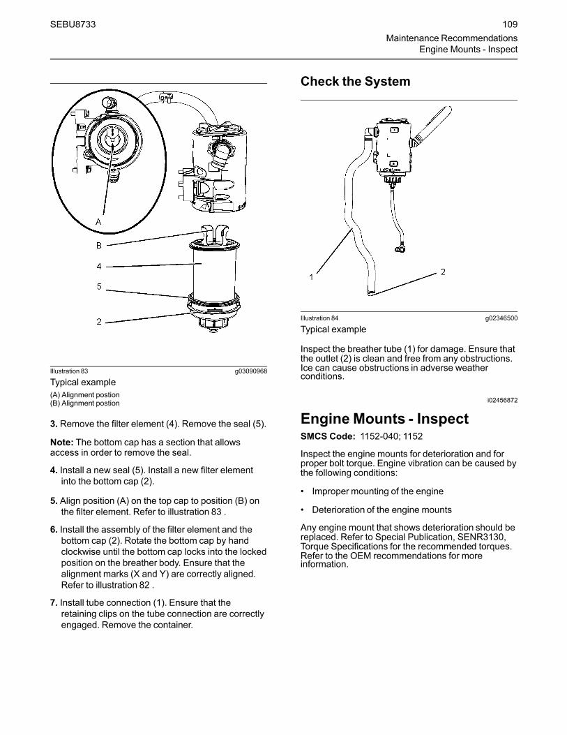
Illustration 83 g03090968
Typical example(A) Alignment postion(B) Alignment postion
3. Remove the filter element (4). Remove the seal (5).
Note: The bottom cap has a section that allowsaccess in order to remove the seal.
4. Install a new seal (5). Install a new filter elementinto the bottom cap (2).
5. Align position (A) on the top cap to position (B) onthe filter element. Refer to illustration 83 .
6. Install the assembly of the filter element and thebottom cap (2). Rotate the bottom cap by handclockwise until the bottom cap locks into the lockedposition on the breather body. Ensure that thealignment marks (X and Y) are correctly aligned.Refer to illustration 82 .
7. Install tube connection (1). Ensure that theretaining clips on the tube connection are correctlyengaged. Remove the container.
Check the System
Illustration 84 g02346500
Typical example
Inspect the breather tube (1) for damage. Ensure thatthe outlet (2) is clean and free from any obstructions.Ice can cause obstructions in adverse weatherconditions.
i02456872
Engine Mounts - InspectSMCS Code: 1152-040; 1152
Inspect the engine mounts for deterioration and forproper bolt torque. Engine vibration can be caused bythe following conditions:
• Improper mounting of the engine
• Deterioration of the engine mounts
Any engine mount that shows deterioration should bereplaced. Refer to Special Publication, SENR3130,Torque Specifications for the recommended torques.Refer to the OEM recommendations for moreinformation.
SEBU8733 109Maintenance Recommendations
Engine Mounts - Inspect

i05300117
Engine Oil Level - CheckSMCS Code: 1348-535-FLV
Hot oil and hot components can cause personalinjury. Do not allow hot oil or hot components tocontact the skin.
Illustration 85 g02173847
“L” Low“H” High
NOTICEPerform this maintenance with the engine stopped.
Note: Ensure that the engine is either level or that theengine is in the normal operating position in order toobtain a true level indication.
Note: After the engine has been switched OFF, waitfor 10 minutes in order to allow the engine oil to drainto the oil pan before checking the oil level.
1.Maintain the oil level between the mark (L) and themark (H) on the engine oil dipstick. Do not fill thecrankcase above the “H” .
NOTICEOperating your engine when the oil level is above the“H” mark could cause your crankshaft to dip into theoil. The air bubbles created from the crankshaft dip-ping into the oil reduces the oils lubricating character-istics and could result in the loss of power.
2. Remove the oil filler cap and add oil, if necessary.Clean the oil filler cap. Install the oil filler cap.
If an increase in the oil level is noticed, refer toTroubleshooting, “Oil Contains Fuel”.
i04237495
Engine Oil Sample - ObtainSMCS Code: 1348-554-SM
In addition to a good preventive maintenanceprogram, Caterpillar recommends using S·O·S oilanalysis at regularly scheduled intervals. S·O·S oilanalysis provides infrared analysis, which is requiredfor determining nitration and oxidation levels.
Obtain the Sample and the Analysis
Hot oil and hot components can cause personalinjury. Do not allow hot oil or hot components tocontact the skin.
Before you take the oil sample, complete the Label,PEEP5031 for identification of the sample. In order tohelp obtain the most accurate analysis, provide thefollowing information:
• Engine model
• Service hours on the engine
• The number of hours that have accumulated sincethe last oil change
• The amount of oil that has been added since thelast oil change
To ensure that the sample is representative of the oilin the crankcase, obtain a warm, mixed oil sample.
To avoid contamination of the oil samples, the toolsand the supplies that are used for obtaining oilsamples must be clean.
Caterpillar recommends using the sampling valve inorder to obtain oil samples. The quality and theconsistency of the samples are better when thesampling valve is used. The location of the samplingvalve allows oil that is flowing under pressure to beobtained during normal engine operation.
The 169-8373 Fluid Sampling Bottle isrecommended for use with the sampling valve. Thefluid sampling bottle includes the parts that areneeded for obtaining oil samples. Instructions arealso provided.
110 SEBU8733Maintenance RecommendationsEngine Oil Level - Check

NOTICEAlways use a designated pump for oil sampling, anduse a separate designated pump for coolant sam-pling. Using the same pump for both types of samplesmay contaminate the samples that are being drawn.This contaminate may cause a false analysis and anincorrect interpretation that could lead to concerns byboth dealers and customers.
If the engine is not equipped with a sampling valve,use the 1U-5718 Vacuum Pump. The pump isdesigned to accept sampling bottles. Disposabletubing must be attached to the pump for insertion intothe sump.
For instructions, see Special Publication, PEGJ0047,“How To Take A Good S·O·S Oil Sample”. Consultyour Cat dealer for complete information andassistance in establishing an S·O·S program for yourengine.
i03996035
Engine Oil and Filter - ChangeSMCS Code: 1318-510
Hot oil and hot components can cause personalinjury. Do not allow hot oil or hot components tocontact the skin.
NOTICECare must be taken to ensure that fluids are con-tained during performance of inspection, mainte-nance, testing, adjusting and repair of the product. Beprepared to collect the fluid with suitable containersbefore opening any compartment or disassemblingany component containing fluids.
Dispose of all fluids according to local regulations andmandates.
NOTICEKeep all parts clean from contaminants.
Contaminants may cause rapid wear and shortenedcomponent life.
Do not drain the engine lubricating oil when theengine is cold. As the engine lubricating oil cools,suspended waste particles settle on the bottom of theoil pan. The waste particles are not removed withdraining cold oil. Drain the oil pan with the enginestopped. Drain the oil pan with the oil warm. Thisdraining method allows the waste particles that aresuspended in the oil to be drained properly.
Failure to follow this recommended procedure willcause the waste particles to be recirculated throughthe engine lubrication system with the new oil.
Drain the Engine LubricatingOilNote: Ensure that the vessel that will be used is largeenough to collect the waste oil.
After the engine has been run at the normal operatingtemperature, stop the engine. Use one of thefollowing methods to drain the engine oil pan:
Illustration 86 g01880893
Typical example
• If the engine is equipped with a drain valve, turnthe drain valve knob counterclockwise in order todrain the oil. After the oil has drained, turn thedrain valve knob clockwise in order to close thedrain valve.
• If the engine is not equipped with a drain valve,remove oil drain plug (1) in order to allow the oil todrain. If the engine is equipped with a shallow oilpan, remove the bottom oil drain plugs from bothends of the oil pan.
After the oil has drained, the oil drain plugs should becleaned and installed. If necessary, replace the O ringseal. Tighten the drain plug to 34 N·m (25 lb ft).
SEBU8733 111Maintenance RecommendationsEngine Oil and Filter - Change

Replace the Oil FilterNOTICE
Caterpillar oil filters are manufactured to Caterpillarspecifications. Use of an oil filter that is not recom-mended by Caterpillar could result in severe damageto the engine bearings, crankshaft, etc., as a result ofthe larger waste particles from unfiltered oil enteringthe engine lubricating system. Only use oil filters rec-ommended by Caterpillar .
1. Remove the oil filter with a 1U-8760ChainWrench.
Note: The following actions can be carried out as partof the preventive maintenance program.
Illustration 87 g01999595
Element with debris
2. Cut the oil filter open with a 175-7546Oil FilterCutter. Break apart the pleats and inspect the oilfilter for metal debris. An excessive amount ofmetal debris in the oil filter may indicate early wearor a pending failure.
Use a magnet to differentiate between the ferrousmetals and the nonferrous metals that are found inthe oil filter element. Ferrous metals may indicatewear on the steel and cast iron parts of the engine.
Nonferrous metals may indicate wear on thealuminum parts, brass parts or bronze parts of theengine. Parts that may be affected include thefollowing items: main bearings, rod bearings,turbocharger bearings and cylinder heads.
Due to normal wear and friction, it is notuncommon to find small amounts of debris in theoil filter. Consult your Caterpillar dealer in order toarrange for a further analysis if an excessiveamount of debris is found in the oil filter.
Illustration 88 g02351361
Typical example
3. Clean the sealing surface of the oil filter base (2).
4. Apply clean engine oil to the O ring seal (3) for thenew oil filter.
NOTICEDo not fill the oil filters with oil before installing them.This oil would not be filtered and could be contami-nated. Contaminated oil can cause accelerated wearto engine components.
5. Install the engine oil filter. Spin on the oil filter untilthe O ring seal contacts the oil filter base. Rotatethe oil filter ¾ of a full turn.
Fill the Oil Pan1. Remove the oil filler cap. Refer to this Operation
and Maintenance Manual, “FluidRecommendations” for more information onsuitable oils. Fill the oil pan with the correct amountof new engine lubricating oil. Refer to thisOperation and Maintenance Manual, “RefillCapacities” for more information on refillcapacities.
112 SEBU8733Maintenance RecommendationsEngine Oil and Filter - Change

NOTICEIf equipped with an auxiliary oil filter system or a re-mote filter system, follow the OEM or the filter manu-factures recommendations. Under filling or over fillingthe crankcase with oil can cause engine damage.
2. Start the engine and run the engine at “LOW IDLE”for 2 minutes. Perform this procedure in order toensure that the lubrication system has oil and thatthe oil filters are filled. Inspect the oil filter for oilleaks.
3. Stop the engine and allow the oil to drain back tothe oil pan for a minimum of 10 minutes.
Illustration 89 g02173847
“L” Low“H” High
4. Remove the engine oil level gauge in order tocheck the oil level. Maintain the oil level betweenthe “L” and “H” marks on the engine oil levelgauge. Do not fill the crankcase above the “H”mark.
i05404932
Fan Clearance - CheckSMCS Code: 1356; 1359; 1360
There are different types of cooling systems that canbe installed. Refer to the Original EquipmentManufactory (OEM) for your application for moreinformation.
Ensure that the engine is stopped and allow 2minutes before the battery disconnect switch isturned off. This procedure will allow the DieselExhaust Fluid (DEF) system to purged.
Ensure that the cooling system is full before checkingthe fan tip clearance. The fan tip clearance is thedistance between the tip of the fan blade (2) and theedge of the cover (1).
SEBU8733 113Maintenance Recommendations
Fan Clearance - Check

Illustration 90 g03414037
Typical example
The gap (A) must be checked in the vertical positionand in the horizontal position.
In the vertical position the gap can be checked at thevertically top position or at the vertically bottomposition.
• Gap (A) vertical top position 12 ± 1 mm(0.47244 ± 0.03937 inch).
• Gap (A) vertical bottom position 8 ± 1 mm(0.31496 ± 0.03937 inch).
After the gap (A) has been checked in the vertical topposition or the vertical bottom position, the horizontalposition must be checked.
• Gap (A) in the horizontal position must be aminimum of 9 mm (0.35433 inch).
If the fan tip clearance requires adjustment, refer tothe Disassembly and Assembly manual for moreinformation.
i04921339
Fuel Filter (In-Line) - ReplaceSMCS Code: 1261-510; 1261
Fuel leaked or spilled onto hot surfaces or electri-cal components can cause a fire. To help preventpossible injury, turn the start switch off whenchanging fuel filters or water separator elements.Clean up fuel spills immediately.
Note: Refer to Systems Operation, Testing, andAdjusting, “Cleanliness of Fuel SystemComponents” for detailed information on thestandards of cleanliness that must be observedduring ALL work on the fuel system.
114 SEBU8733Maintenance RecommendationsFuel Filter (In-Line) - Replace

NOTICEEnsure that the engine is stopped before any servic-ing or repair is performed.
The location of the in-line fuel filter will depend on theapplication that the engine has been installed.
Illustration 91 g03086919
Typical example
1. Turn the fuel supply valve (if equipped) to the OFFposition. Remove any brackets that hold the in-linefuel filter (1) in place, refer to OEM information.
2. Release the hose clips (3) and remove the hoselines from the in-line fuel filter. Remove the in-linefilter.
3. Install a new in-line filter and secure, refer to OEMinformation. Ensure that the arrow mark (2) isaligned to the direction of fuel flow from the tank tothe fuel pump.
4. Install the fuel hose lines and install the hose clips(3). Turn the fuel supply valve (if equipped) to theON position.
5. The in-line fuel filter must be changed with theprimary filter and the secondary fuel filter.
i03906114
Fuel System - PrimeSMCS Code: 1250-548; 1258-548
Note: Refer to Systems Operation, Testing, andAdjusting, “Cleanliness of Fuel SystemComponents” for detailed information on thestandards of cleanliness that must be observedduring ALL work on the fuel system.
Ensure that all adjustments and repairs areperformed by authorized personnel that have had thecorrect training.
NOTICEDo not crank the engine continuously for more than30 seconds. Allow the starting motor to cool for twominutes before cranking the engine again.
If air enters the fuel system, the air must be purgedfrom the fuel system before the engine can bestarted. Air can enter the fuel system when thefollowing events occur:
• The fuel tank is empty or the fuel tank has beenpartially drained.
• The low-pressure fuel lines are disconnected.
• A leak exists in the low-pressure fuel system.
• The fuel filter has been replaced.
Use the following procedures in order to remove airfrom the fuel system:
1. Ensure that the fuel system is in working order.Check that the fuel supply valve (if equipped) is inthe “ON” position.
2. Turn the keyswitch to the “RUN” position.
3. The keyswitch will allow the electric priming pumpto operate. Operate the electric priming pump. TheECM will stop the pump after 2 minutes.
4. Turn the keyswitch to the “OFF” position. The fuelsystem should now be primed and the engineshould be able to start.
5. Operate the engine starter and crank the engine.After the engine has started, operate the engine atlow idle for a minimum of 5 minutes. Ensure thatthe fuel system is free from leaks.
Note:Operating the engine for this period will helpensure that the fuel system is free of air. DO NOTloosen the high-pressure fuel lines in order topurge air from the fuel system. This procedure isnot required.
SEBU8733 115Maintenance Recommendations
Fuel System - Prime

After the engine has stopped, you must wait for 10minutes in order to allow the fuel pressure to bepurged from the high-pressure fuel lines before anyservice or repair is performed on the engine fuel lines.If necessary, performminor adjustments. Repair anyleaks from the low-pressure fuel system and from thecooling, lubrication, or air systems. Replace any high-pressure fuel line that has leaked. Refer toDisassembly and Assembly Manual, “Fuel InjectionLines - Install”.
If you inspect the engine in operation, always use theproper inspection procedure in order to avoid a fluidpenetration hazard . Refer to Operation andMaintenance Manual, “General hazard Information”.
If the engine will not start, refer to Troubleshooting,“Engine Cranks but will not Start”.
i04921313
Fuel System Primary Filter(Water Separator) Element -ReplaceSMCS Code: 1260-510-FQ; 1263-510-FQ
Fuel leaked or spilled onto hot surfaces or electri-cal components can cause a fire. To help preventpossible injury, turn the start switch off whenchanging fuel filters or water separator elements.Clean up fuel spills immediately.
Note: Refer to Systems Operation, Testing, andAdjusting, “Cleanliness of Fuel SystemComponents” for detailed information on thestandards of cleanliness that must be observedduring ALL work on the fuel system.
NOTICEEnsure that the engine is stopped before any servic-ing or repair is performed.
Remove the Element1. Turn the fuel supply valve (if equipped) to the OFF
position before performing this maintenance.
2. Place a suitable container under the waterseparator in order to catch any fuel that might spill.Clean up any spilled fuel. Clean the outside bodyof the filter assembly.
Illustration 92 g03086757
Typical example
3. Install a suitable tube onto drain (3). Open the drainvalve (2). Rotate the drain valve counterclockwise.Two full turns are required.
4. Loosen the vent screw (1).
5. Allow the fuel to drain into the container. Removethe tube from the drain valve.
6. Tighten the vent screw (1) securely . Remove thewiring harness from connection (4).
7. Rotate filter bowl (6) counterclockwise and removethe filter bowl from assembly. Refer to yourcaterpillar dealer for the correct tool.
116 SEBU8733Maintenance RecommendationsFuel System Primary Filter (Water Separator) Element - Replace

Illustration 93 g02148402
Typical example
8. Rotate the filter element (5) counterclockwise andremove the filter element . Clean the filter bowl.
Install the New Filter Element
Illustration 94 g03086798
Typical example
1. Locate the thread in the new filter element (8) ontothe threads (9). Spin on the filter element andtighten the drain valve (2) securely.
2. Lubricate the O ring seal (7) with clean engine oil.Do NOT fill the bowl with fuel before the assemblyis installed.
3. Do not use a tool in order to install the filterassembly. Tighten the filter bowl (6) by hand.Install the filter bowl (6). Turn the filter bowlclockwise until the filter bowl locks into positionagainst the stops.
4. Remove the container and dispose of the fuel in asafe place.
5. The secondary filter element must be replaced atthe same time as the primary filter element. Also,the in-line filter must be changed. Refer to theOperation and Maintenance Manual, “Fuel SystemFilter - Replace”.
SEBU8733 117Maintenance Recommendations
Fuel System Primary Filter (Water Separator) Element - Replace

i04925799
Fuel System Primary Filter/Water Separator - DrainSMCS Code: 1260-543; 1263-543
Fuel leaked or spilled onto hot surfaces or electri-cal components can cause a fire. To help preventpossible injury, turn the start switch off whenchanging fuel filters or water separator elements.Clean up fuel spills immediately.
NOTICEEnsure that the engine is stopped before any servic-ing or repair is performed.
NOTICEThe water separator can be under suction during nor-mal engine operation. Ensure that the drain valve istightened securely to help prevent air from enteringthe fuel system.
1. Place a suitable container under the waterseparator in order to catch any fluid that might spill.Clean up any spilled fluid.
2. Ensure that the outer body of the filter assembly isclean and free from dirt.
Illustration 95 g02148370
Typical example
3. Install a suitable tube onto drain (3). Open the drainvalve (2). Rotate the drain valve counterclockwise.Two full turns are required. Loosen vent screw (1).
4. Allow the fluid to drain into the container.
5. Tighten the drain valve clockwise by hand pressureonly. Remove the tube and remove the container.
6. Tighten the vent screw securely.
i04921888
Fuel System Secondary Filter -ReplaceSMCS Code: 1261-510-SE
Fuel leaked or spilled onto hot surfaces or electri-cal components can cause a fire. To help preventpossible injury, turn the start switch off whenchanging fuel filters or water separator elements.Clean up fuel spills immediately.
NOTICEEnsure that the engine is stopped before any servic-ing or repair is performed.
Refer to Systems Operation, Testing, andAdjusting, “Cleanliness of Fuel SystemComponents” for detailed information on thestandards of cleanliness that must be observedduring ALL work on the fuel system.
Remove the Element1. Turn the fuel supply valve (if equipped) to the OFF
position before performing this maintenance.
2. Place a suitable container under the fuel filter inorder to catch any fuel that might spill. Clean upany spilled fuel. Clean the outside body of the filterassembly.
118 SEBU8733Maintenance RecommendationsFuel System Primary Filter/Water Separator - Drain

Illustration 96 g03088718
3. Install a suitable tube onto drain (4). Open the drainvalve (3). Rotate the drain valve counterclockwise.Two full turns are required. Loosen vent screw (1).
4. Allow the fuel to drain into the container andremove the tube.
5. Tighten the vent screw (1) securely.
6. Remove the filter bowl (2). Rotate the filterassembly counterclockwise in order to remove theassembly. Refer to your caterpillar dealer for thecorrect tool number.
Illustration 97 g02546456
7. Rotate the filter element (5) counterclockwise andremove the filter element. Clean the filter bowl.
Install the Element
Illustration 98 g03088837
1. Locate the thread (7) in the filter element onto thethreads (8). Spin on the element and tighten thedrain valve (3) by hand.
2. Lubricate the O ring seal (6) with clean engine oil.Do NOT fill the filter bowl (2) with fuel before thefilter assembly is installed.
SEBU8733 119Maintenance Recommendations
Fuel System Secondary Filter - Replace
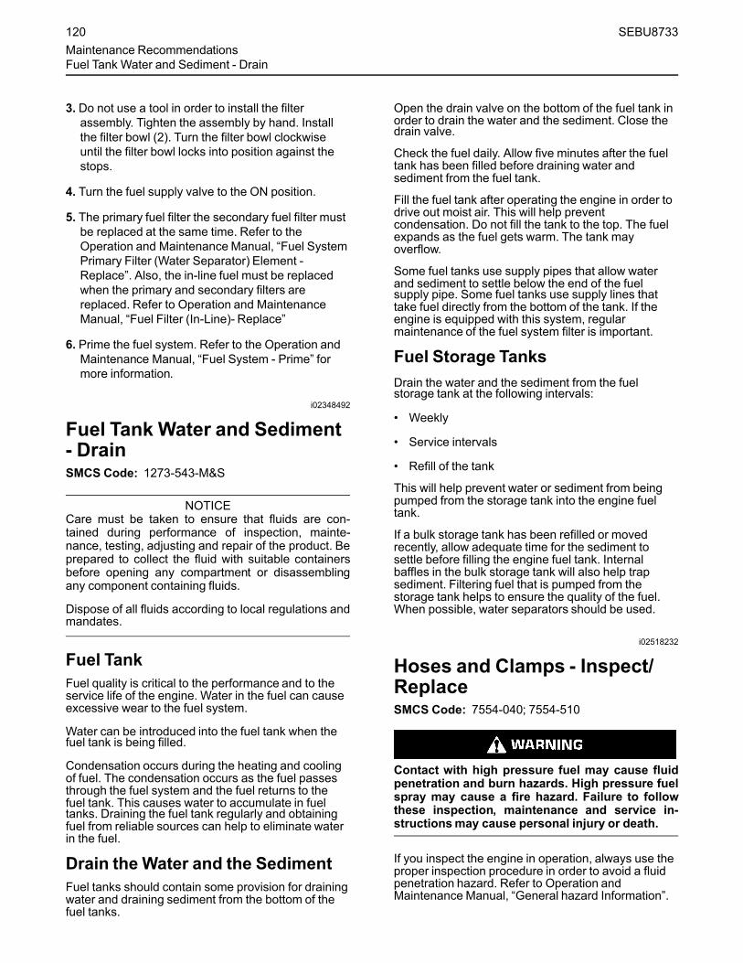
3. Do not use a tool in order to install the filterassembly. Tighten the assembly by hand. Installthe filter bowl (2). Turn the filter bowl clockwiseuntil the filter bowl locks into position against thestops.
4. Turn the fuel supply valve to the ON position.
5. The primary fuel filter the secondary fuel filter mustbe replaced at the same time. Refer to theOperation and Maintenance Manual, “Fuel SystemPrimary Filter (Water Separator) Element -Replace”. Also, the in-line fuel must be replacedwhen the primary and secondary filters arereplaced. Refer to Operation and MaintenanceManual, “Fuel Filter (In-Line)- Replace”
6. Prime the fuel system. Refer to the Operation andMaintenance Manual, “Fuel System - Prime” formore information.
i02348492
Fuel Tank Water and Sediment- DrainSMCS Code: 1273-543-M&S
NOTICECare must be taken to ensure that fluids are con-tained during performance of inspection, mainte-nance, testing, adjusting and repair of the product. Beprepared to collect the fluid with suitable containersbefore opening any compartment or disassemblingany component containing fluids.
Dispose of all fluids according to local regulations andmandates.
Fuel TankFuel quality is critical to the performance and to theservice life of the engine. Water in the fuel can causeexcessive wear to the fuel system.
Water can be introduced into the fuel tank when thefuel tank is being filled.
Condensation occurs during the heating and coolingof fuel. The condensation occurs as the fuel passesthrough the fuel system and the fuel returns to thefuel tank. This causes water to accumulate in fueltanks. Draining the fuel tank regularly and obtainingfuel from reliable sources can help to eliminate waterin the fuel.
Drain the Water and the SedimentFuel tanks should contain some provision for drainingwater and draining sediment from the bottom of thefuel tanks.
Open the drain valve on the bottom of the fuel tank inorder to drain the water and the sediment. Close thedrain valve.
Check the fuel daily. Allow five minutes after the fueltank has been filled before draining water andsediment from the fuel tank.
Fill the fuel tank after operating the engine in order todrive out moist air. This will help preventcondensation. Do not fill the tank to the top. The fuelexpands as the fuel gets warm. The tank mayoverflow.
Some fuel tanks use supply pipes that allow waterand sediment to settle below the end of the fuelsupply pipe. Some fuel tanks use supply lines thattake fuel directly from the bottom of the tank. If theengine is equipped with this system, regularmaintenance of the fuel system filter is important.
Fuel Storage TanksDrain the water and the sediment from the fuelstorage tank at the following intervals:
• Weekly
• Service intervals
• Refill of the tank
This will help prevent water or sediment from beingpumped from the storage tank into the engine fueltank.
If a bulk storage tank has been refilled or movedrecently, allow adequate time for the sediment tosettle before filling the engine fuel tank. Internalbaffles in the bulk storage tank will also help trapsediment. Filtering fuel that is pumped from thestorage tank helps to ensure the quality of the fuel.When possible, water separators should be used.
i02518232
Hoses and Clamps - Inspect/ReplaceSMCS Code: 7554-040; 7554-510
Contact with high pressure fuel may cause fluidpenetration and burn hazards. High pressure fuelspray may cause a fire hazard. Failure to followthese inspection, maintenance and service in-structionsmay cause personal injury or death.
If you inspect the engine in operation, always use theproper inspection procedure in order to avoid a fluidpenetration hazard. Refer to Operation andMaintenance Manual, “General hazard Information”.
120 SEBU8733Maintenance RecommendationsFuel Tank Water and Sediment - Drain

Inspect all hoses for leaks that are caused by thefollowing conditions:
• Cracking
• Softness
• Loose clamps
Replace hoses that are cracked or soft. Tighten anyloose clamps.
Check for the following conditions:
• End fittings that are damaged or leaking
• Outer covering that is chafed or cut
• Exposed wire that is used for reinforcement
• Outer covering that is ballooning locally
• Flexible part of the hose that is kinked or crushed
• Armoring that is embedded in the outer covering
A constant torque hose clamp can be used in place ofany standard hose clamp. Ensure that the constanttorque hose clamp is the same size as the standardclamp.
Due to extreme temperature changes, the hose willharden. Hardening of the hoses will cause hoseclamps to loosen. This can result in leaks. A constanttorque hose clamp will help to prevent loose hoseclamps.
Each installation application can be different. Thedifferences depend on the following factors:
• Type of hose
• Type of fitting material
• Anticipated expansion and contraction of the hose
• Anticipated expansion and contraction of thefittings
Replace the Hoses and the ClampsRefer to the OEM information for further informationon removing and replacing fuel hoses (if equipped).
The following text describes a typical method ofreplacing coolant hoses. Refer to the OEMinformation for further information on the coolantsystem and the hoses for the coolant system.
Pressurized System: Hot coolant can cause seri-ous burns. To open the cooling system filler cap,stop the engine and wait until the cooling systemcomponents are cool. Loosen the cooling systempressure cap slowly in order to relieve thepressure.
1. Stop the engine. Allow the engine to cool.
2. Loosen the cooling system filler cap slowly in orderto relieve any pressure. Remove the coolingsystem filler cap.
Note: Drain the coolant into a suitable, cleancontainer. The coolant can be reused.3. Drain the coolant from the cooling system to a level
that is below the hose that is being replaced.
4. Remove the hose clamps.
5. Disconnect the old hose.
6. Replace the old hose with a new hose.
7. Install the hose clamps with a torque wrench.
Note: For the correct coolant, see this Operation andMaintenance Manual, “Fluid Recommendations”.8. Refill the cooling system. Refer to the OEM
information for further information on refilling thecooling system.
9. Clean the cooling system filler cap. Inspect thecooling system filler cap's seals. Replace thecooling system filler cap if the seals are damaged.Install the cooling system filler cap.
10. Start the engine. Inspect the cooling system forleaks.
i05414590
Injector (Diesel Exhaust Fluid) -ReplaceSMCS Code: 108I-510
SEBU8733 121Maintenance Recommendations
Injector (Diesel Exhaust Fluid) - Replace

Illustration 99 g03418548
Typical example
Illustration 100 g03418553
Typical example
1. Drain the coolant in order to remove the coolantlines (1). Remove the cooling lines (1) and removeDiesel Exhaust Fluid (DEF) line (2).
2. Remove electrical connect from position (3) andinstall protection caps to DEF injector (5). Removenuts (4) and washers (9) from DEF injector (5) andremove DEF injector from Clean Emission Module(CEM) (6).
Illustration 101 g03418578
Typical example
3. Remove gasket (7) and remove the studs (8).Discard the gasket and the studs.
4. Ensure that the sealing face of the CEM is cleanand free from dirt.
5. Apply bostik pure nickel ant-seize compound toends of the new studs (8). Install the coated endsof the new studs into the CEM, and tighten to atorque of 5 N·m (44 lb in).
6. Install new gasket (7), ensure that the metal side ofthe gasket is to the CEM. Install new DEF injector(5) to CEM (6).
7. Install washers (9) and apply bostik pure nickelant-seize compound to the threads of the studs (8).
8. Install the nuts (4) and tighten the nuts to a torqueof 5 N·m (44 lb in). Retighten the nuts to 5 N·m(44 lb in). Then, turn the nuts additional 90degrees.
9. Install electrical connection into position (3) andinstall DEF line (2). Install coolant lines (1).
10. Fill cooling system to the correct level. Ensurethat the correct specification of coolant is used.
If available, using the electronic service tool (ET)perform DEF Dosing System Verification test.
122 SEBU8733Maintenance RecommendationsInjector (Diesel Exhaust Fluid) - Replace

i04224312
Overhaul ConsiderationsSMCS Code: 7595-043
Reduced hours of operation at full load will result in alower average power demand. A decreased averagepower demand should increase both the engineservice life and the overhaul interval.
The need for an overhaul is indicated by increasedfuel consumption, increased oil consumption,excessive engine blowby, and reduced power. Arctictemperatures, extreme high temperatures, corrosiveenvironments, or extreme dusty conditions contributeto premature wear and the need for an overhaul.
The following factors are important when a decision isbeing made on the proper time for an engineoverhaul:
• The need for preventive maintenance
• The quality of the fuel that is being used
• The operating conditions
• The results of the S·O·S analysis
Oil Consumption as an OverhaulIndicatorOil consumption, fuel consumption, and maintenanceinformation can be used to estimate the totaloperating cost for your Caterpillar engine. Oilconsumption can also be used to estimate therequired capacity of a makeup oil tank that is suitablefor the maintenance intervals.
Oil consumption is in proportion to the percentage ofthe rated engine load. As the percentage of theengine load is increased, the amount of oil that isconsumed per hour also increases.
The oil consumption rate (brake-specific oilconsumption) is measured in grams per kW/h (lb perbhp). The brake-specific oil consumption (BSOC)depends on the engine load. Consult your Caterpillardealer for assistance in determining the typical oilconsumption rate for your engine.
When an engines oil consumption has risen to threetimes the original oil consumption rate due to normalwear, an engine overhaul should be scheduled. Theremay be a corresponding increase in blowby and aslight increase in fuel consumption.
Overhaul Options
Before Failure OverhaulA planned overhaul before failure may be the bestvalue for the following reasons:
• Costly unplanned downtime can be avoided.
• Many original parts can be reused according to thestandards for reusable parts.
• The engines service life can be extended withoutthe risk of a major catastrophe due to enginefailure.
• The best cost/value relationship per hour ofextended life can be attained.
After Failure OverhaulIf a major engine failure occurs and the engine mustbe removed, many options are available. An overhaulshould be performed if the engine block or thecrankshaft needs to be repaired.
If the engine block is repairable and/or the crankshaftis repairable, the overhaul cost will be less than thecost of a new engine with a similar exchange core.
This lower cost can be attributed to three aspects:
• Specially designed Caterpillar engine features
• Caterpillar dealer exchange components
• Caterpillar Inc. remanufactured exchangecomponents
Overhaul RecommendationTo minimize downtime, Caterpillar Inc. recommendsa scheduled engine overhaul by your Caterpillardealer before the engine fails. This process willprovide you with the best cost/value relationship.
Note:Overhaul programs vary according to theengine application and according to the dealer thatperforms the overhaul. Consult your Caterpillardealer for specific information about the availableoverhaul programs and about overhaul services forextending the engine life.
AftertreatmentThe aftertreatment system can be expected tofunction properly for the useful life of the engine(emissions durability period), as defined byregulation, subject to prescribed maintenancerequirements being followed.
Rebuild or Exchange
If an overhaul is performed without overhaul servicefrom your Caterpillar dealer, be aware of thefollowing maintenance recommendations.
SEBU8733 123Maintenance Recommendations
Overhaul Considerations

Cylinder Head Assembly, Oil Pump, andFuel Transfer Pump
These components should be inspected according tothe instructions that are found in various Caterpillarreusability publications. The Special Publication,SEBF8029 lists the reusability publications that areneeded for inspecting the engine parts.
If the parts comply with the established inspectionspecifications that are expressed in the reusableparts guideline, the parts should be reused.
Parts that are not within the established inspectionspecifications should be dealt with in one of thefollowing manners:
• Salvaging
• Repairing
• Replacing
Using out-of-spec parts can result in the followingproblems:
• Unscheduled downtime
• Costly repairs
• Damage to other engine parts
• Reduced engine efficiency
• Increased fuel consumption
Reduced engine efficiency and increased fuelconsumption translates into higher operating costs.Therefore, Caterpillar Inc. recommends repairing out-of-spec parts or replacing out-of-spec parts.
Inspection and/or Replacement
Crankshaft Bearings Crankshaft Sealsand PistonsThe following components may not last until thesecond overhaul.
• Thrust bearings
• Main bearings
• Rod bearings
• Crankshaft seals
• Piston assembly
Caterpillar Inc. recommends the installation of newparts at each overhaul period.
Inspect these parts while the engine is disassembledfor an overhaul.
Inspect the crankshaft for any of the followingconditions:
• Deflection
• Damage to the journals
• Bearing material that has seized to the journals
Check the journal taper and the profile of thecrankshaft journals. If the wear patterns on the rodbearing or the main bearing show a problem, thecrankshaft will need to be measured with specialistequipment.
Inspect the camshaft for damage to the journals andto the lobes.
Note: If the camshaft is removed for any reason, usethe magnetic particle inspection process to check forcracks in the camshaft.
Inspect the following components for signs of wear orfor signs of scuffing:
• Camshaft bearings
• Lifters
Caterpillar Inc. recommends replacing the crankshaftvibration damper.
Oil Cooler CoreDuring an overhaul, Caterpillar Inc. recommends theremoval of the oil cooler core. Clean the oil coolercore. Then, pressure test the oil cooler core.
NOTICEDo not use caustic cleaners to clean the core.
Caustic cleaners can attack the internal metals of thecore and cause leakage.
Note: Use this cleaning procedure to clean the oilcooler core.
1. Remove the oil cooler core.
2. Remove any debris from the oil cooler core. Toremove debris from the oil cooler core, turn the oilcooler core onto one end.
3. Flush the oil cooler core internally with cleaner inorder to loosen foreign substances. This flushingwill also help to remove oil from the oil cooler core.
Note: Caterpillar Inc. recommends the use ofHydrosolv Liquid Cleaners. Table 19 lists theHydrosolv Liquid Cleaners that are available fromyour Caterpillar dealer.
124 SEBU8733Maintenance RecommendationsOverhaul Considerations

Table 19
Hydrosolv Liquid Cleaners
Part Number Description Size
1U-8812
Hydrosolv 4165
4 L (1 US gallon)
1U-5490 19 L (5 US gallon)
8T-7570 208 L (55 US gallon)
1U-8804
Hydrosolv 100
4 L (1 US gallon)
1U-5492 19 L (5 US gallon)
8T-5571 208 L (55 US gallon)
4. Use steam to clean the oil cooler core. The steamwill remove any remaining residue from thecleaner. Flush the fins of the oil cooler core.Remove any other trapped debris.
5.Wash the oil cooler core with hot, soapy water.Rinse the oil cooler core thoroughly with cleanwater.
Personal injury can result from air pressure.
Personal injury can result without following prop-er procedure. When using pressure air, wear aprotective face shield and protective clothing.
Maximum air pressure at the nozzle must be lessthan 205 kPa (30 psi) for cleaning purposes.
6. Dry the oil cooler core with compressed air. Directthe air in the reverse direction of the normal flow.
7. Inspect the components in order to ensurecleanliness. The oil cooler core should be pressuretested. Repair the oil cooler core, if necessary.Install the oil cooler core.
For more information about cleaning the cores,consult your Caterpillar dealer.
Obtain Coolant Analysis
The concentration of supplemental coolant additive(SCA) should be checked regularly with test kits orwith S·O·S Coolant Analysis (Level 1). Furthercoolant analysis is recommended when the engine isoverhauled.
For example, considerable deposits are found in thewater jacket areas on the external cooling system, butthe concentrations of coolant additives were carefullymaintained. The coolant probably contained mineralsthat were deposited on the engine over time.
A coolant analysis can be conducted in order to verifythe condition of the water that is being used in thecooling system. A full water analysis can be obtainedby consulting your local water utility company or anagricultural agent. Private laboratories are alsoavailable for water analysis.
Caterpillar Inc. recommends an S·O·S CoolantAnalysis (Level 2).
S·O·S Coolant Analysis (Level 2)
An S·O·S Coolant Analysis (Level 2) is acomprehensive coolant analysis which completelyanalyzes the coolant and the effects on the coolingsystem. An S·O·S Coolant Analysis (Level 2)provides the following information:
• Complete S·O·S Coolant Analysis (Level 1)
• Visual inspection of properties
• Identification of metal corrosion
• Identification of contaminants
• Identification of built up impurities (corrosion andscale)
S·O·S Coolant Analysis (Level 2) provides a report ofthe results of both the analysis and the maintenancerecommendations.
For more information about coolant analysis, see yourCaterpillar dealer.
i04020194
Radiator - CleanSMCS Code: 1353-070
Note: Adjust the frequency of cleaning according tothe effects of the operating environment.
Inspect the radiator for these items: damaged fins,corrosion, dirt, grease, insects, leaves, oil and otherdebris. Clean the radiator, if necessary.
Personal injury can result from air pressure.
Personal injury can result without following prop-er procedure. When using pressure air, wear aprotective face shield and protective clothing.
The maximum air pressure for cleaning purposesmust be reduced to 205 kPa (30 psi) when the airnozzle is deadheaded.
SEBU8733 125Maintenance Recommendations
Radiator - Clean
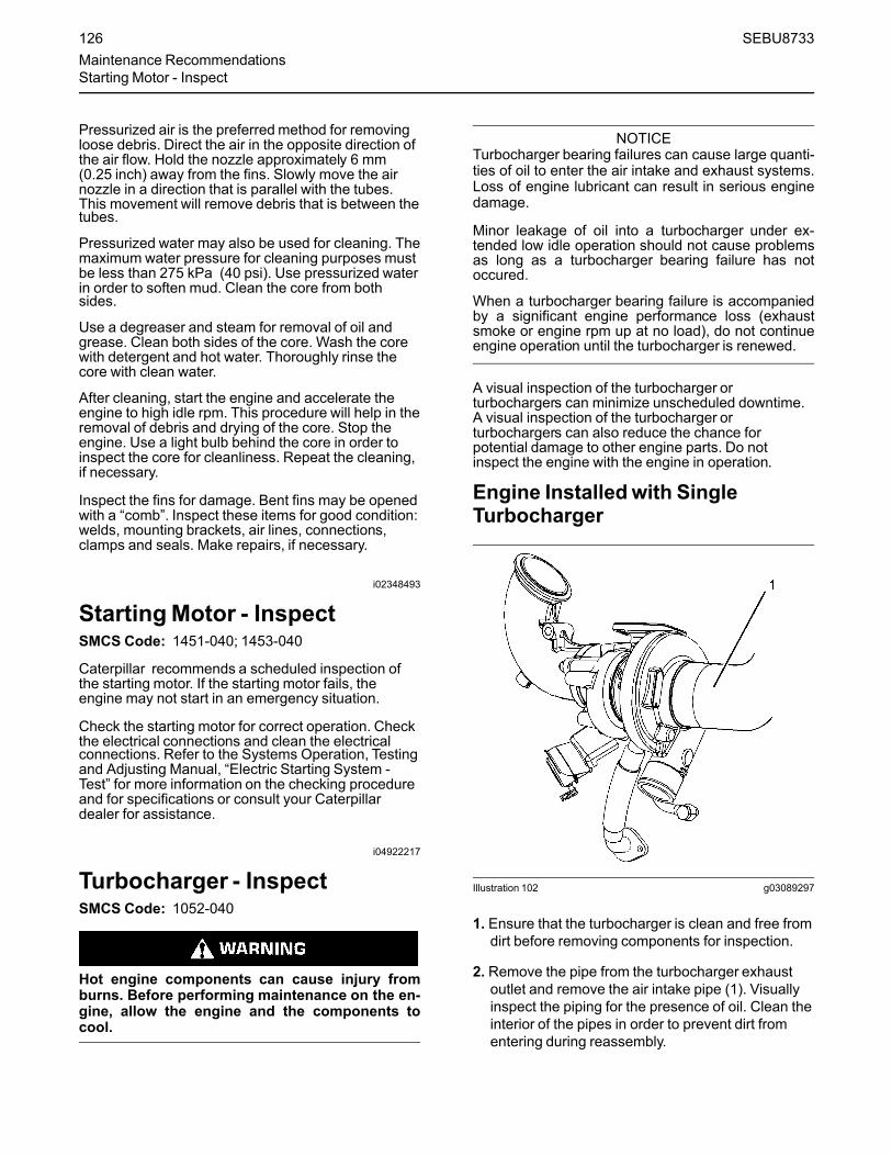
Pressurized air is the preferredmethod for removingloose debris. Direct the air in the opposite direction ofthe air flow. Hold the nozzle approximately 6 mm(0.25 inch) away from the fins. Slowly move the airnozzle in a direction that is parallel with the tubes.This movement will remove debris that is between thetubes.
Pressurized water may also be used for cleaning. Themaximumwater pressure for cleaning purposes mustbe less than 275 kPa (40 psi). Use pressurized waterin order to soften mud. Clean the core from bothsides.
Use a degreaser and steam for removal of oil andgrease. Clean both sides of the core. Wash the corewith detergent and hot water. Thoroughly rinse thecore with clean water.
After cleaning, start the engine and accelerate theengine to high idle rpm. This procedure will help in theremoval of debris and drying of the core. Stop theengine. Use a light bulb behind the core in order toinspect the core for cleanliness. Repeat the cleaning,if necessary.
Inspect the fins for damage. Bent fins may be openedwith a “comb”. Inspect these items for good condition:welds, mounting brackets, air lines, connections,clamps and seals. Make repairs, if necessary.
i02348493
StartingMotor - InspectSMCS Code: 1451-040; 1453-040
Caterpillar recommends a scheduled inspection ofthe starting motor. If the starting motor fails, theengine may not start in an emergency situation.
Check the starting motor for correct operation. Checkthe electrical connections and clean the electricalconnections. Refer to the Systems Operation, Testingand Adjusting Manual, “Electric Starting System -Test” for more information on the checking procedureand for specifications or consult your Caterpillardealer for assistance.
i04922217
Turbocharger - InspectSMCS Code: 1052-040
Hot engine components can cause injury fromburns. Before performing maintenance on the en-gine, allow the engine and the components tocool.
NOTICETurbocharger bearing failures can cause large quanti-ties of oil to enter the air intake and exhaust systems.Loss of engine lubricant can result in serious enginedamage.
Minor leakage of oil into a turbocharger under ex-tended low idle operation should not cause problemsas long as a turbocharger bearing failure has notoccured.
When a turbocharger bearing failure is accompaniedby a significant engine performance loss (exhaustsmoke or engine rpm up at no load), do not continueengine operation until the turbocharger is renewed.
A visual inspection of the turbocharger orturbochargers can minimize unscheduled downtime.A visual inspection of the turbocharger orturbochargers can also reduce the chance forpotential damage to other engine parts. Do notinspect the engine with the engine in operation.
Engine Installedwith SingleTurbocharger
Illustration 102 g03089297
1. Ensure that the turbocharger is clean and free fromdirt before removing components for inspection.
2. Remove the pipe from the turbocharger exhaustoutlet and remove the air intake pipe (1). Visuallyinspect the piping for the presence of oil. Clean theinterior of the pipes in order to prevent dirt fromentering during reassembly.
126 SEBU8733Maintenance RecommendationsStarting Motor - Inspect

3. Check for obvious heat discoloration of theturbocharger. Check for any loose bolts or anymissing bolts. Check for damage to the oil supplyline and the oil drain line. Check for cracks in thehousing of the turbocharger. Ensure that thecompressor wheel can rotate freely.
4. Check for the presence of oil. If oil is leaking fromthe back side of the compressor wheel, there is apossibility of a failed turbocharger oil seal.
The presence of oil may be the result of extendedengine operation at low idle. The presence of oilmay also be the result of a restriction of the line forthe intake air (clogged air filters), which causes theturbocharger to slobber.
5. Install the air intake pipe and the exhaust outletpipe to the turbocharger housing. Ensure that allclamps are installed correctly and that all clampsare tightened securely. For more information, referto Systems Operation, Testing, and Adjusting,“Turbocharger - Inspect”.
Engine Installedwith High PressureTurbocharger and Low PressureTurbocharger
Illustration 103 g03089316
The engine is equipped with a high-pressureturbocharger (1) and a low-pressure turbocharger (4).A regular visual inspection of both turbochargers isrecommended. If the turbocharger fails during engineoperation, damage to the turbocharger compressorwheel and/or to the engine may occur. Damage to theturbocharger compressor wheel can damage thepistons, the valves, and the cylinder head.
1. Ensure that the turbochargers are clean and freefrom dirt before removing components forinspection.
2. Remove the pipe from the high-pressureturbocharger exhaust outlet and remove the airintake pipe (3 ) to the turbocharger. Visuallyinspect the piping for the presence of oil. Clean theinterior of the pipes in order to prevent dirt fromentering during reassembly.
3. Remove elbow (2) and check for the presence ofengine oil.
4. Check for obvious heat discoloration of theturbocharger. Check for any loose bolts or anymissing bolts. Check for damage to the oil supplyline and the oil drain line. Check for cracks in thehousing of the turbocharger. Ensure that thecompressor wheel can rotate freely.
5. Check for the presence of oil. If oil is leaking fromthe back side of the compressor wheel, there is apossibility of a failed turbocharger oil seal.
The presence of oil may be the result of extendedengine operation at low idle. The presence of oilmay also be the result of a restriction of the line forthe intake air (clogged air filters), which causes theturbocharger to slobber.
6. Inspect the bore of the housing of the turbine outletfor corrosion.
7. Install the air intake pipe and the exhaust outletpipe to the turbocharger housing. Ensure that allclamps are installed correctly and that all clampsare tightened securely. For more information, referto Systems Operation, Testing, and Adjusting,“Turbocharger - Inspect”.
SEBU8733 127Maintenance Recommendations
Turbocharger - Inspect

i05431557
Walk-Around InspectionSMCS Code: 1000-040
Inspect the Tube of the CrankcaseBreather
Illustration 104 g02351425
Typical example
Inspect the breather tube (1) for damage. Ensure thatthe outlet (2) is clean and free from any obstructions.Ice can cause obstructions in adverse weatherconditions.
Inspect the Engine for Leaks andfor Loose ConnectionsA walk-around inspection should only take a fewminutes. When the time is taken to perform thesechecks, costly repairs and accidents can be avoided.
For maximum engine service life, make a thoroughinspection of the engine compartment before startingthe engine. Look for items such as oil leaks or coolantleaks, loose bolts, worn belts, loose connections, andtrash buildup. Make repairs, as needed:
• The guards must be in the correct place. Repairdamaged guards or replace missing guards.
• Wipe all caps and plugs before the engine isserviced in order to reduce the chance of systemcontamination.
NOTICEFor any type of leak (coolant, lube, or fuel) clean upthe fluid. If leaking is observed, find the source andcorrect the leak. If leaking is suspected, check the flu-id levels more often than recommended until the leakis found or fixed, or until the suspicion of a leak isproved to be unwarranted.
NOTICEAccumulated grease and/or oil on an engine is a firehazard. Remove the accumulated grease and oil. Re-fer to this Operation and Maintenance Manual, “En-gine - Clean” for more information.
• Ensure that the cooling system hoses are correctlyclamped and that the cooling system hoses aretight. Check for leaks. Check the condition of allpipes.
• Inspect the water pump for coolant leaks.
Note: The water pump seal is lubricated by thecoolant in the cooling system. It is normal for a smallamount of leakage to occur as the engine cools downand the parts contract.
Excessive coolant leakage may indicate the need toreplace the water pump. Remove the water pump.Refer to Disassembly and Assembly, “Water Pump -Remove and Install”. For more information, consultyour Caterpillar dealer.
• Inspect the lubrication system for leaks at the frontcrankshaft seal, the rear crankshaft seal, the oilpan, the oil filters, and the rocker cover.
• Inspect the piping for the air intake system and theelbows for cracks and for loose clamps. Ensurethat hoses and tubes are not contacting otherhoses, tubes, wiring harnesses, etc.
• Ensure that the areas around the rotating parts areclear.
• Inspect the alternator belts and any accessorydrive belts for cracks, breaks, or other damage.
• Inspect the wiring harness for damage.
Belts for multiple groove pulleys must be replaced asmatched sets. If only one belt is replaced, the belt willcarry more load than the belts that are not replaced.The older belts are stretched. The additional load onthe new belt could cause the belt to break.
128 SEBU8733Maintenance RecommendationsWalk-Around Inspection

High Pressure Fuel Lines
Contact with high pressure fuel may cause fluidpenetration and burn hazards. High pressure fuelspray may cause a fire hazard. Failure to followthese inspection, maintenance and service in-structionsmay cause personal injury or death.
After the engine has stopped, you must wait for 10minutes in order to allow the fuel pressure to bepurged from the high-pressure fuel lines before anyservice or repair is performed on the engine fuel lines.If necessary, performminor adjustments. Repair anyleaks from the low-pressure fuel system and from thecooling, lubrication, or air systems. Replace any high-pressure fuel line that has leaked. Refer toDisassembly and Assembly Manual, “Fuel InjectionLines - Install”.
If you inspect the engine in operation, always use theproper inspection procedure in order to avoid a fluidpenetration hazard. Refer to Operation andMaintenance Manual, “General hazard Information”.
Visually inspect the high-pressure fuel lines fordamage or signs of fuel leakage. Replace anydamaged high-pressure fuel lines or high-pressurefuel lines that have leaked.
Ensure that all clips on the high-pressure fuel linesare in place and that the clips are not loose.
• Inspect the rest of the fuel system for leaks. Lookfor loose fuel line clamps.
• Drain the water and the sediment from the fueltank on a daily basis in order to ensure that onlyclean fuel enters the fuel system.
• Inspect the wiring and the wiring harnesses forloose connections and for worn wires or frayedwires. Check for any loose tie-wraps or missing tie-wraps.
• Inspect the ground strap for a good connectionand for good condition.
• Disconnect any battery chargers that are notprotected against the current drain of the startingmotor. Check the condition and the electrolytelevel of the batteries, unless the engine isequipped with a maintenance free battery.
• Check the condition of the gauges. Replace anygauges that are cracked. Replace any gauge thatcannot be calibrated.
Engine AftertreatmentCheck the condition of the coolant lines , DieselExhaust Fluid (DEF) lines, and electrical connections.Check that all clamps, clips, and tie-wraps are secureand in good condition. Check that the DEF filler cap issecure and that cap is clean and free from dirt.
Check the level of DEF in the tank is adequate foroperational purpose, if necessary fill the tank.
i03570653
Water Pump - InspectSMCS Code: 1361-040
A failed water pump may cause severe engineoverheating problems that could result in the followingconditions:
• Cracks in the cylinder head
• A piston seizure
• Other potential damage to the engine
Illustration 105 g01904773
(A) Weep hole(B) Vent hole
Note: The water pump seals are lubricated by thecoolant in the cooling system. It is normal for a smallamount of leakage to occur. Refer to illustration 105for the position of the weep hole and the vent hole.
SEBU8733 129Maintenance Recommendations
Water Pump - Inspect

Visually inspect the water pump for leaks.
Note: If engine coolant enters the engine lubricatingsystem the lubricating oil and the engine oil filter mustbe replaced. This will remove any contamination thatis caused by the coolant and this will prevent anyirregular oil samples.
The water pump is not a serviceable item. In order toinstall a new water pump, refer to the Disassemblyand Assembly Manual, “Water Pump - Remove andInstall”.
130 SEBU8733Maintenance RecommendationsWater Pump - Inspect
Warranty Section
Warranty Informationi04141951
Emissions WarrantyInformationSMCS Code: 1000
Caterpillar Inc. (Caterpillar ) warrants to the ultimatepurchaser and each subsequent purchaser that:
1. New non-road diesel engines and stationary dieselengines less than 10 liters per cylinder operatedand serviced in the United States and Canada ,including all parts of their emission control systems(“emission related components”), are:
a. Designed, built, and equipped so as toconform, at the time of sale, with applicableemission standards prescribed by the UnitedStates Environmental Protection Agency (EPA) by way of regulation.
b. Free from defects in materials andworkmanship in emission-related componentsthat can cause the engine to fail to conform toapplicable emission standards for the warrantyperiod.
2. New non-road diesel engines operated andserviced in the state of California , including allparts of their emission control systems (“emissionrelated components”), are:
a. Designed, built, and equipped so as toconform, at the time of sale, to all applicableregulations adopted by the California AirResources Board (ARB ).
b. Free from defects in materials andworkmanship which cause the failure of anemission-related component to be identical inall material respects to the component asdescribed in the Caterpillar application forcertification for the warranty period.
A detailed explanation of the Emission ControlWarranty that is applicable to new non-road andstationary diesel engines, including the componentscovered and the warranty period, is found insupplement Special Publication, SELF9001, “FederalEmission Control Warranty” and “Emission ControlWarranty for California”. Consult your authorized Catdealer to determine if your engine is subject to anEmission Control Warranty.
SEBU8733 131Warranty Section
Emissions Warranty Information

Reference InformationSection
Engine Ratingsi03579032
Engine Rating ConditionsSMCS Code: 1000
It is important to know the use of the engine so thatthe rating will match the operating profile. The properrating selection is also important so that thecustomer's perception of price and value is realized.
In selecting a rating for a specific application, themost important consideration is the time that is spentat full throttle. The rating definitions identify thepercent of time at full throttle. The definitions alsoidentify the corresponding times below rated rpm.
Note: For an exact determination of the appropriaterating, follow the OEM specifications or consult yourCaterpillar dealer.
There are five ratings from A to E. The rating for theC7.1 industrial engine is C.
C – Intermittent service in conjunction with maximumpower and/or speed are cyclic. The engine at full loadshould not exceed 50 percent of the duty cycle.
NOTICEOperating engines above the rating definitions can re-sult in shorter service life before overhaul.
i04650089
Engine Rating DefinitionsSMCS Code: 1000
All engine ratings are in compliance with the followingstandard ambient air conditions of ISO14396:2002:
• 100 kPa (29.3 Inches Hg)
• 30 percent relative humidity
• A temperature of 25 °C (77 °F)
The engine ratings are based on the following fuelspecifications:
• The Low Heat Value (LHV) of the fuel at 29 °C(84.2 °F) at 42780 kJ/kg (18390 Btu/lb)
• Specific gravity of .833 - 837 at 15 °C (60 °F)
The engine ratings are gross output ratings.
Gross Output Ratings – The total output capabilityof the engine that is equipped with standardaccessories.
Standard accessories include the followingcomponents:
• Oil pumps
• Fuel pumps
• Water pumps
Subtract the power that is required to drive auxiliarycomponents from the gross output. This process willproduce the net power that is available for theexternal load (flywheel).
132 SEBU8733Reference Information SectionEngine Rating Conditions

Customer Servicei03996951
Customer AssistanceSMCS Code: 1000; 4450
USA and CanadaWhen a problem arises concerning the operation orthe service of an engine, the problem will normally bemanaged by the dealer in your area.
Outside of the USA and of CanadaIf a problem arises outside the USA and outsideCanada , and if the problem cannot be resolved at thedealer level, consult the appropriate Caterpillaroffice.
Latin America, Mexico, CarribeanCaterpillar Americas Co.701 WaterfordWay, Suite 200Miami, FL 33126-4670USAPhone: 305-476-6800Fax: 305-476-6801
Europe, Africa, and Middle EastCaterpillar Overseas S.A.76 Route de FrontenexP.O. Box 6000CH-1211 Geneva 6SwitzerlandPhone: 22-849-4444Fax: 22-849-4544
Far EastCaterpillar Asia Pte. Ltd.7 Tractor RoadJurong, Singapore 627968Republic of SingaporePhone: 65-662-8333Fax: 65-662-8302
ChinaCaterpillar China Ltd.37/F., The Lee Gardens33 Hysan AvenueCauseway BayG.P.O. Box 3069Hong KongPhone: 852-2848-0333Fax: 852-2848-0440
JapanShin Caterpillar Mitsubishi Ltd.SBS Tower10-1, Yoga 4-ChomeSetagaya-Ku, Tokyo 158-8530JapanPhone: 81-3-5717-1150Fax: 81-3-5717-1177
JapanCaterpillar Power Systems, Inc.SBS Tower (14th floor)4-10-1, YogaSetagaya-Ku, Tokyo 158-0097Phone: 81-3-5797-4300Fax: 81-3-5797-4359
Australia and New ZealandCaterpillar of Australia Ltd.1 Caterpillar DrivePrivate Mail Bag 4Tullamarine, Victoria 3043AustraliaPhone: 03-9953-9333Fax: 03-9335-3366
i03655027
Ordering Replacement PartsSMCS Code: 4450; 7567
When replacement parts are required for thisproduct Caterpillar recommends using Caterpil-lar replacement parts or parts with equivalentspecifications including, but not limited to, physi-cal dimensions, type, strength and material.
Failure to heed this warning can lead to prematurefailures, product damage, personal injury ordeath.
Quality Caterpillar replacement parts are availablefrom Caterpillar dealers throughout the world.Caterpillar dealers' parts inventories are up-to-date.The parts stocks include all of the parts that arenormally needed to protect your Caterpillar engineinvestment.
When you order parts, please specify the followinginformation:
SEBU8733 133Customer Service
Customer Assistance

• When a Caterpillar engine requires maintenanceand/or repair, provide the dealer with all theinformation that is stamped on the InformationPlate. Refer to this Operation and MaintenanceManual, “Plate Locations and Film Locations”.
• Part number
• Part name
• Quantity
If there is a question concerning the part number,please provide your dealer with a completedescription of the needed item.
Discuss the problem with the dealer. Inform thedealer about the conditions of the problem and thenature of the problem. Inform the dealer about whenthe problem occurs. This will help the dealer introubleshooting the problem and solving the problemfaster.
134 SEBU8733Customer ServiceOrdering Replacement Parts

ReferenceMaterialsi05264255
MaintenanceRecordsSMCS Code: 1000; 4450
Caterpillar Inc. recommends the retention of accuratemaintenance records. Accurate maintenance recordscan be used for the following purposes:
• Determine operating costs.
• Establish maintenance schedules for otherengines that are operated in the sameenvironment.
• Show compliance with the required maintenancepractices and maintenance intervals.
Maintenance records can be used for various otherbusiness decisions that are related to enginemaintenance.
Maintenance records are a key element of amaintenance program that is managed. Accuratemaintenance records can help your Cat dealer tofine-tune the recommended maintenance intervals inorder to meet the specific operating situation. Thisshould result in a lower engine operating cost.
Records should be kept for the following items:
Fuel Consumption – A record of fuel consumption isessential in order to determine when the loadsensitive components should be inspected orrepaired. Fuel consumption also determines overhaulintervals.
Service Hours – A record of service hours isessential to determine when the speed sensitivecomponents should be inspected or repaired.
Documents – These items should be easy to obtain,and these items should be kept in the engine historyfile. All of the documents should show thisinformation: date, service hours, fuel consumption,unit number and engine serial number. The followingtypes of documents should be kept as proof ofmaintenance or repair for warranty:
Keep the following types of documents as proof ofmaintenance for warranty. Also, keep these types ofdocuments as proof of repair for warranty:
• Dealer work orders and itemized bills
• Owner repair costs
• Owner receipts
• Maintenance log
SEBU8733 135Reference Materials
Maintenance Records

i01176304
MaintenanceLogSMCS Code: 1000; 4450
Table 20
Engine Model Customer Identifier
Serial Number Arrangement Number
ServiceHours
QuantityOfFuel Service Item Date Authorization
136 SEBU8733Reference MaterialsMaintenance Log

i05432178
Reference MaterialSMCS Code: 1000; 4450
The following literature can be obtained through anyCaterpillar dealer.
Lubricants• Operation and Maintenance Manual, SEBU5898,
“Cold Weather Recommendations”
• Operation and Maintenance Manual, SEBU6251,“Caterpillar Commercial Diesel Engine FluidsRecommendations”
• Special Publication, PEHP6001, “How To Take AGood Oil Sample”
Coolants• Special Publication, PEHP4036, “Data Sheet -
Extended Life Coolant”
• Special Publication, PEHP7057, “Data Sheet -S·O·S Coolant Analysis”
• Special Publication, SEBD0518, “Know YourCooling System”
• Label, PEEP5027, “Extended Life Coolant/Antifreeze”
Miscellaneous• Service Manual, REG1139F, “Service Manual
Contents Microfiche”
• Service Manual, UENR4452, “C7.1 IndustrialEngines”
• Troubleshooting, UENR0668, “C7.1 IndustrialEngines”
• Systems Operation, Testing, and Adjusting,UENR0666, “C7.1 Industrial Engines”
• Specifications, UENR0665, “C7.1 IndustrialEngines.”
• Disassembly and Assembly, UENR0667, “C7.1Industrial Engines”
• Specifications, SENR3130, “TorqueSpecifications”
• Special Publication, PECP9067, “One SafeSource” English language for use in NACD
• Special Publication, SEBF8029, “Index toGuidelines for Reusable Parts and SalvageOperations”
• Special Publication, SEBF8062, “Procedure toInspect and Clean Air Filters”
• Special Instruction, SEHS9031, “StorageProcedure for Caterpillar Products”
• Special Publication, NEHS0526, “ServiceTechnician Application Guide”
• Special Publication, SEBU6251, “CaterpillarCommercial Diesel Engine FluidsRecommendations”
• Special Instruction, SEHS7633, “Battery TestProcedure”
SEBU8733 137Reference MaterialsReference Material
Index
AAfter Starting Engine........................................ 66After Stopping Engine...................................... 75Aftercooler Core - Clean/Test (Air-To-AirAftercooler) .................................................... 88Aftercooler Core - Inspect................................ 88Alarms and Shutoffs ........................................ 37Alarms.......................................................... 37Shutoffs........................................................ 37Testing.......................................................... 38
Alternator - Inspect .......................................... 88Alternator and Fan Belts - Replace.................. 89
BBattery - Replace............................................. 89Battery Disconnect Switch (If Equipped) ......... 41Battery Electrolyte Level - Check .................... 89Battery or Battery Cable - Disconnect ............. 90Before Starting Engine ...............................17, 64Belt - Inspect.................................................... 91Belt Tensioner - Check..................................... 90Burn Prevention............................................... 12AftertreatmentSystem ................................. 12Batteries....................................................... 12Coolant......................................................... 12Induction System ......................................... 12Oils............................................................... 12
CCold Weather Operation.................................. 69Hints for Cold Weather Operation................ 69Idling the Engine .......................................... 70Recommendations for Coolant Warm Up .... 70Recommendations for the Coolant .............. 70Viscosity of the Engine Lubrication Oil......... 70
Cold Weather Starting ..................................... 64Configuration Parameters................................ 60Customer Specified Parameters.................. 61System Configuration Parameters............... 60
Coolant (DEAC) - Change ............................... 91Cooling Systems with Heavy Deposits orPlugging ..................................................... 93Drain ............................................................ 91Fill................................................................. 93Flush ............................................................ 92
Coolant (ELC) - Change .................................. 94Drain ............................................................ 94Fill................................................................. 95Flush ............................................................ 95
Coolant Extender (ELC) - Add......................... 96Coolant Level - Check ..................................... 97Coolant Sample (Level 1) - Obtain .................. 97Coolant Sample (Level 2) - Obtain .................. 98Cooling System Supplemental CoolantAdditive (SCA) - Test/Add .............................. 99Add the SCA, If Necessary ........................ 100S·O·S Coolant Analysis ............................... 99Test for SCA Concentration ......................... 99
Crankshaft Vibration Damper - Inspect.......... 100Viscous Damper......................................... 100
Crushing Prevention and Cutting Prevention .. 15Customer Assistance..................................... 133Outside of the USA and of Canada ........... 133USA and Canada ...................................... 133
Customer Service .......................................... 133
DDiagnostic Flash Code Retrieval ..................... 59Diagnostic Lamp.............................................. 59Diesel Exhaust Fluid - Fill .............................. 101Diesel Exhaust Fluid Filter - Clean/Replace.. 101Diesel Exhaust Fluid in Cold Weather ............. 73Driven Equipment - Check............................. 102
EElectrical System............................................. 18Grounding Practices .................................... 18
Emergency Stopping ....................................... 74Emergency Stop Button............................... 75
Emissions Certification Film ............................ 31Emissions Warranty Information.................... 131Engaging the Driven Equipment...................... 67Engine - Clean............................................... 102Aftertreatment ............................................ 102
Engine Air Cleaner Element (Dual Element)- Inspect/Clean/Replace .............................. 102Cleaning the Primary Air Cleaner Elements................................................................. 103
Servicing the Air Cleaner Elements ........... 102Engine Air Cleaner Element (SingleElement) - Inspect/Replace ......................... 105
138 SEBU8733Index Section
Engine Air Cleaner Service Indicator -Inspect ......................................................... 105Test the Service Indicator........................... 105
Engine Air Precleaner - Check/Clean............ 106Engine Crankcase Breather Element -Replace........................................................ 106Bottom Service........................................... 108Check the System...................................... 109Top Service ................................................ 107
Engine Diagnostics.......................................... 59Engine Electronics........................................... 19Engine Mounts - Inspect................................ 109Engine Oil and Filter - Change .......................111Drain the Engine Lubricating Oil .................111Fill the Oil Pan.............................................112Replace the Oil Filter...................................112
Engine Oil Level - Check ................................110Engine Oil Sample - Obtain ............................110Obtain the Sample and the Analysis...........110
Engine Operation............................................. 67Engine Operation and the AftertreatmentSystem ....................................................... 67
Engine Operation with Active DiagnosticCodes ............................................................ 59Engine Operation with IntermittentDiagnostic Codes........................................... 60Engine Rating Conditions.............................. 132Engine Rating Definitions .............................. 132Engine Ratings .............................................. 132Engine Starting...........................................17, 64Engine Stopping .........................................18, 74
FFan Clearance - Check...................................113Fault Logging................................................... 59Features and Controls ..................................... 37Fire Prevention and Explosion Prevention ...... 13Ether ............................................................ 14Fire Extinguisher.......................................... 14Lines, Tubes, and Hoses ............................. 15
Fluid Recommendations.................................. 76Coolant......................................................... 81Diesel Exhaust Fluid .................................... 79Engine Lubrication Oil.................................. 76Fuel .............................................................. 78Lubricating Grease....................................... 78S·O·S Coolant Analysis ............................... 81
Foreword............................................................ 4California Proposition 65 Warning ................. 4Literature Information..................................... 4
Maintenance .................................................. 4Maintenance Intervals.................................... 4Operation ....................................................... 4Overhaul ........................................................ 4Safety............................................................. 4
Fuel and the Effect from Cold Weather............ 72Fuel Conservation Practices............................ 68Fuel Filter (In-Line) - Replace .........................114Fuel Related Components in Cold Weather .... 72Fuel Filters ................................................... 72Fuel Heaters ................................................ 73Fuel Tanks.................................................... 72
Fuel System - Prime .......................................115Fuel System Primary Filter (WaterSeparator) Element - Replace ......................116Install the New Filter Element .....................117Remove the Element ..................................116
Fuel System Primary Filter/Water Separator- Drain ...........................................................118Fuel System Secondary Filter - Replace ........118Install the Element ......................................119Remove the Element ..................................118
Fuel Tank Water and Sediment - Drain.......... 120Drain the Water and the Sediment............. 120Fuel Storage Tanks .................................... 120Fuel Tank ................................................... 120
GGauges and Indicators .................................... 41Aftertreatment Lamps and gauges............... 42Indicator Lamps ........................................... 42
General Hazard Information .............................. 8Containing Fluid Spillage ............................. 10Dispose of Waste Properly............................11Fluid Penetration.......................................... 10Inhalation ......................................................11Pressurized Air and Water ........................... 10
General Information......................................... 21
HHigh Pressure Fuel Lines ................................ 15Hoses and Clamps - Inspect/Replace........... 120Replace the Hoses and the Clamps .......... 121
IImportant Safety Information ............................. 2Injector (Diesel Exhaust Fluid) - Replace ...... 121
SEBU8733 139Index Section

LLifting and Storage........................................... 33
MMaintenance Interval Schedule ....................... 87Daily ............................................................. 87Every 1000 Service Hours ........................... 87Every 12 000 Service Hours or 6 Years ....... 88Every 1500 Service Hours ........................... 87Every 2000 Service Hours ........................... 87Every 250 Service Hours ............................. 87Every 3000 Service Hours ........................... 87Every 3000 Service Hours or 2 Years .......... 87Every 4000 Service Hours ........................... 87Every 50 Service Hours or Weekly .............. 87Every 500 Service Hours ............................. 87Every 500 Service Hours or 1 Year.............. 87Every 5000 Service Hours ........................... 87Every 6000 Service Hours or 3 Years .......... 88Every Week.................................................. 87Every Year.................................................... 87Overhaul ...................................................... 88When Required............................................ 87
Maintenance Log ........................................... 136Maintenance Recommendations..................... 83Maintenance Records.................................... 135Maintenance Section....................................... 76Model View Illustrations................................... 21Engine AftertreatmentSystem..................... 26Engine Views with Series Turbochargers .... 22Off Engine Components............................... 25Single Turbocharged Engine with InstalledAftertreatment ............................................ 21
Monitoring System (Engine Indicators andAftertreatment Indicators) .............................. 43Engine Indicator Lamps ............................... 43
Mounting and Dismounting.............................. 15
OOperation Section............................................ 33Ordering Replacement Parts ......................... 133Overhaul Considerations............................... 123Oil Consumption as an Overhaul Indicator................................................................. 123
Overhaul Recommendation....................... 123Overspeed....................................................... 44
PPlate Locations and Film Locations................. 30Serial Number Plate..................................... 30
Plate Locations and Film Locations(Aftertreatment System)................................. 30Clean Emission Module (CEM).................... 30Pump Electronic Tank Unit (PETU).............. 31
Product Description (Engine andAftertreatment)............................................... 27Aftermarket Products and Caterpillar Engines................................................................... 29
AftertreatmentSystem ................................. 29Electronic Engine Features.......................... 28Engine Cooling and Lubrication................... 29Engine Diagnostics ...................................... 28Engine Service Life ...................................... 29Engine Specifications .................................. 28
Product Identification Information.................... 30Product Information Section ............................ 21Product Lifting.................................................. 33Engine and Clean Emission Module (CEM)................................................................... 33
Product Storage............................................... 35Aftertreatment .............................................. 35
RRadiator - Clean............................................. 125Radiator Restrictions ....................................... 71Reference Information..................................... 32Record for Reference................................... 32
Reference Information Section...................... 132ReferenceMaterial ........................................ 137Coolants..................................................... 137Lubricants .................................................. 137Miscellaneous............................................ 137
ReferenceMaterials ...................................... 135Refill Capacities............................................... 76Cooling System............................................ 76Lubrication System ...................................... 76
SSafety Messages............................................... 5Ether Warning 2 ............................................. 6Hand (High Pressure) 3 ................................. 7Universal Warning 1....................................... 5
Safety Section ................................................... 5Selective Catalytic ReductionWarningSystem........................................................... 38
140 SEBU8733Index Section

Warning Indicators ....................................... 38Warning Levels ............................................ 38Warning Strategy ......................................... 38
Self-Diagnostics............................................... 59Sensors and Electrical Components ............... 44AftertreatmentComponents......................... 54CEM Sensors............................................... 55Clean Emissions Module (CEM).................. 54Engine Components .................................... 45Pump Electronic Tank Unit (PETU).............. 57
Severe Service Application.............................. 85ImproperMaintenance Procedures(Maintenance ProceduresWhich MayContribute to a Severe Service Application)................................................................... 86
Severe Environmental Factors .................... 85Severe Operating Conditions....................... 85
Starting Motor - Inspect ................................. 126Starting the Engine .......................................... 65Starting the Engine ...................................... 65
Starting with Jump Start Cables ...................... 65Stopping the Engine ........................................ 74Delayed Engine Shutdown (if Equipped) ..... 74
System Pressure Release............................... 83Coolant System............................................ 83Engine Oil .................................................... 83Fuel System................................................. 83
TTable of Contents............................................... 3Turbocharger - Inspect .................................. 126Engine Installed with High PressureTurbocharger and Low PressureTurbocharger............................................ 127Engine Installed with Single Turbocharger................................................................. 126
WWalk-Around Inspection ................................ 128Engine Aftertreatment................................ 129High Pressure Fuel Lines........................... 129Inspect the Engine for Leaks and for LooseConnections ............................................. 128Inspect the Tube of the Crankcase Breather................................................................. 128
Warranty Information ..................................... 131Warranty Section ........................................... 131Water Pump - Inspect .................................... 129
Welding on Engines with Electronic Controls .. 83
SEBU8733 141Index Section

142 SEBU8733Index Section

Product and Dealer InformationNote: Forproduct identification plate locations, see the section “Product IdentificationInformation” in the Operation and Maintenance Manual.
Delivery Date:
Product InformationModel:
Product Identification Number:
Engine Serial Number:
TransmissionSerial Number:
Generator Serial Number:
Attachment Serial Numbers:
Attachment Information:
Customer Equipment Number:
Dealer EquipmentNumber:
Dealer InformationName: Branch:
Address:
DealerContact
PhoneNumber
Hours
Sales:
Parts:
Service:

©2013 CaterpillarAll Rights Reserved
CAT, CATERPILLAR, their respective logos, “Caterpillar Yellow”, and the POWER EDGE tradedress as well as corporate and product identity used herein, are trademarks of Caterpillar andmay not be used without permission.