Operation and Maintenance Manual MNS-SG Low … · Low Voltage, Metal-Enclosed, Drawout Switchgear...
45
MNS-SG Low Voltage, Metal-Enclosed, Drawout Switchgear Operation and Maintenance Manual
Transcript of Operation and Maintenance Manual MNS-SG Low … · Low Voltage, Metal-Enclosed, Drawout Switchgear...

MNS-SGLow Voltage, Metal-Enclosed, Drawout Switchgear
Operation and Maintenance Manual

2 MNS-SG Operation and Maintenance | Manual

Manual | MNS-SG Operation and Maintenance 3
Important User Information ....................................................4 Safety Notices ..........................................................................4
1. General Information and System Description ..................6 1.1. System overview ........................................................6 1.2. Component names ....................................................6 1.3. Technical data table ...................................................7 1.4. MNS-SGstandardconfiguration................. ..............8 1.4.1. Structure description..................................................8 1.5. Labels and markings .................................................8 1.5.1. Switchgear lineup label .............................................8 1.5.2. Cubicle/device label ...................................................8 1.6. Mechanical design ....................................................8 1.6.1. Section arrangement .................................................8 1.7. Busbar compartments ...............................................9 1.7.1. Bus phases................................................................9 1.7.2. Horizontal neutral bus (optional feature) ...................10 1.7.3. Ground bar .............................................................10 1.7.4. Vertical distribution busbar ......................................11 1.8. Device compartment ...............................................11 1.8.1. Section and location numbering ..............................11 1.9. Wireways ................................................................12 1.9.1. Cable compartment .................................................12 1.9.2. Top horizontal wireway .............................................12 1.9.3. Bottom horizontal wireway ......................................12 1.9.4. Vertical wireway ......................................................13 2. Exhaust Plenum (Optional) ..............................................14 2.1. Install side-exhaust plenum ..................................... 15 2.2. Install rear-exhaust plenum ......................................16 2.3. Positioning arc-resistant switchgear ........................18 3. Packaging and Handling ..................................................19 3.1. Standard packaging ................................................19 3.2. Section weight .........................................................20 3.3. Receiving ................................................................21 3.4. Unload and move switchgear components .............21 3.4.1. Loading and transport ............................................22 3.4.2. Ground transport ....................................................22 3.4.3. Transport by crane ...................................................23 3.4.4. Temporary storage ...................................................24 4. Locate and Connect the Switchgear ..............................25 4.1. Installation location requirements ............................25 4.2. Installation guidelines ..............................................26 4.3. Section installation sequence ...................................26 4.4. Install and connect shipping splits ...........................26 4.4.1. Position shipping splits ...........................................26 4.4.2. Connect sections ....................................................26
4.5. Splice horizontal busbars ........................................27 4.6. Attachswitchgeartothefloor .................................29 4.7. Attach overhead lifting device .................................29 4.7.1. Operating overhead lifting device ............................31 4.8. Connect cable and wiring .......................................31 4.8.1. Install connections – general information .................31 4.8.2. Direct connections to main sections ........................34 4.8.3. Connect between horizontal and vertical wireways ..........34 4.8.4. Connect control wiring between sections .....................34 4.8.5. Connection to external control source (If required) ..........34 4.9. Other installation information ...................................34 4.9.1. Interruption of installation ........................................34 4.9.2. Surface damage .....................................................34 4.10. Commission the switchgear ....................................34 4.10.1. Physical equipment check ......................................34 4.10.2. Prepare to energize switchgear ................................35 4.10.3.Testingandfinalinspection .....................................36 4.10.4. Energize the switchgear ..........................................38 4.10.5. Energize the main bus .............................................38 4.10.6. Final testing ............................................................38 5. Component Operation Documents ................................38 6. Maintenance .....................................................................38 6.1. Lockout/Tagout ......................................................38 6.2. Tighten unit control and power terminals .................39 6.3. Remove/insert withdrawable breaker .......................39 6.4. Inspect units ...........................................................39 6.5. Inspect busbars ......................................................39 6.6. Exterior metal damage repair ...................................39 6.7 Maintenance schedule ............................................39 6.7.1 Semi-annual inspection ...........................................40 6.7.2 Annual inspection ...................................................40 6.7.3 18-to-36 month inspection ......................................40 6.7.4 10-year maximum inspection ..................................40 6.7.5 Eslok® fasteners ......................................................40 6.8 Arcflashprotection .................................................41 7. Additional Resources ......................................................41 8. Torque Fasteners .............................................................41 8.1. Torque table ............................................................42 9. Optional Accessories ......................................................43 9.1. Maintenance switch .................................................43 10.Disclaimer of Warranties and Limitation of Liability .......................................................44
Table of Contents
4 MNS-SG Operation and Maintenance | Manual
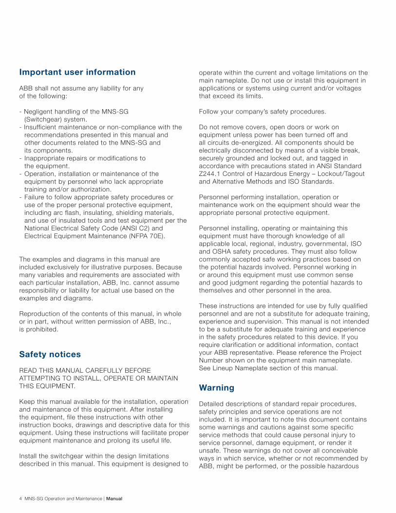
Important user information
ABB shall not assume any liability for any of the following:
- Negligent handling of the MNS-SG (Switchgear) system.- Insufficient maintenance or non-compliance with the recommendations presented in this manual and other documents related to the MNS-SG and its components.- Inappropriate repairs or modifications to the equipment.- Operation, installation or maintenance of the equipment by personnel who lack appropriate training and/or authorization.- Failure to follow appropriate safety procedures or use of the proper personal protective equipment, including arc flash, insulating, shielding materials, and use of insulated tools and test equipment per the National Electrical Safety Code (ANSI C2) and Electrical Equipment Maintenance (NFPA 70E).
The examples and diagrams in this manual are included exclusively for illustrative purposes. Because many variables and requirements are associated with each particular installation, ABB, Inc. cannot assume responsibility or liability for actual use based on the examples and diagrams.
Reproduction of the contents of this manual, in whole or in part, without written permission of ABB, Inc., is prohibited.
Safety notices
READ THIS MANUAL CAREFULLY BEFORE ATTEMPTING TO INSTALL, OPERATE OR MAINTAIN THIS EQUIPMENT.
Keep this manual available for the installation, operation and maintenance of this equipment. After installing the equipment, file these instructions with other instruction books, drawings and descriptive data for this equipment. Using these instructions will facilitate proper equipment maintenance and prolong its useful life.
Install the switchgear within the design limitations described in this manual. This equipment is designed to
operate within the current and voltage limitations on the main nameplate. Do not use or install this equipment in applications or systems using current and/or voltages that exceed its limits.
Follow your company’s safety procedures. Do not remove covers, open doors or work on equipment unless power has been turned off and all circuits de-energized. All components should be electrically disconnected by means of a visible break, securely grounded and locked out, and tagged in accordance with precautions stated in ANSI Standard Z244.1 Control of Hazardous Energy – Lockout/Tagout and Alternative Methods and ISO Standards.
Personnel performing installation, operation or maintenance work on the equipment should wear the appropriate personal protective equipment.
Personnel installing, operating or maintaining this equipment must have thorough knowledge of all applicable local, regional, industry, governmental, ISO and OSHA safety procedures. They must also follow commonly accepted safe working practices based on the potential hazards involved. Personnel working in or around this equipment must use common sense and good judgment regarding the potential hazards to themselves and other personnel in the area.
These instructions are intended for use by fully qualified personnel and are not a substitute for adequate training, experience and supervision. This manual is not intended to be a substitute for adequate training and experience in the safety procedures related to this device. If you require clarification or additional information, contact your ABB representative. Please reference the Project Number shown on the equipment main nameplate. See Lineup Nameplate section of this manual.
Warning
Detailed descriptions of standard repair procedures, safety principles and service operations are not included. It is important to note this document contains some warnings and cautions against some specific service methods that could cause personal injury to service personnel, damage equipment, or render it unsafe. These warnings do not cover all conceivable ways in which service, whether or not recommended by ABB, might be performed, or the possible hazardous
Manual | MNS-SG Operation and Maintenance 5
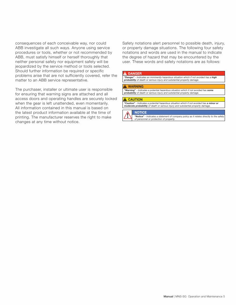
consequences of each conceivable way, nor could ABB investigate all such ways. Anyone using service procedures or tools, whether or not recommended by ABB, must satisfy himself or herself thoroughly that neither personal safety nor equipment safety will be jeopardized by the service method or tools selected. Should further information be required or specific problems arise that are not sufficiently covered, refer the matter to an ABB service representative.
The purchaser, installer or ultimate user is responsible for ensuring that warning signs are attached and all access doors and operating handles are securely locked when the gear is left unattended, even momentarily.All information contained in this manual is based on the latest product information available at the time of printing. The manufacturer reserves the right to make changes at any time without notice.
Safety notations alert personnel to possible death, injury, or property damage situations. The following four safety notations and words are used in the manual to indicate the degree of hazard that may be encountered by the user. These words and safety notations are as follows:

6 MNS-SG Operation and Maintenance | Manual
1. General information and system description
1.1. System overview
The MNS-SG switchgear consists of one or more vertical metal cabinets referred to as “sections.” Each section includes three separate compartments: device, busbar and cable compartment.
Each section contains up to four compartment locations that may contain breakers, instruments and/or empty compartments that are used to control, protect and isolate electrical equipment.
All sections include a top and a bottom horizontal wireway for control wiring.
Units feature front, hinged doors held closed by one or more latches.
The rear door is secured by a swing handle with a door-lock mechanism that secures the door at four points of contact.
The unit door is interlocked with the disconnecting means, preventing the door from being opened when the breaker is in the ON position. The unit door can only be opened when the breaker is in the OFF position.
A continuous horizontal bus, rated 1,600 to 5,000 amps, distributes incoming power to all switchgear sections. The horizontal bus is located in the bottom half of each section, and for tie applications a similar assembly is used at the top of the section. Each section may contain a system of vertical bus, rated 1,600A up to 5,000A. The vertical bus is located in the busbar compartment, segregated from the device compartment.
1.2. Component names
This manual uses the following naming conventions:
Blank Unit: An empty compartment.
Compartment: Sections are typically divided into three compartments: Device, busbar and cable. See Mechanical Design - Section Arrangement.
Cubicle: See Section.
Device: An instrument compartment, breaker compartment, empty compartment or an equipped space feeder.
Equipped Space Feeder: An empty compartment with the cradle and pilot light, control and other wiring already in place, ready for the addition of a breaker.
Lineup: The arrangement of several vertical sections, joined side-by-side, to create a complete switchgear with a continuous horizontal bus.
Mimic Bus: Consists of a series of electrical symbols and designations used on the exterior of large switchgear panels that mimic the wiring scheme within the panel.
Module: The equipment compartment within a section is sometimes divided into smaller modules to accommodate devices of different heights. One section may be divided into as many as four modules.
Section: An enclosed, vertical metal cabinet that contains devices, wireways and other internal constructions. Several sections are typically combined next to one another to form a switchgear lineup.
Shipping Split: Up to three vertical sections are arranged and joined side-by-side at the factory. This facilitates shipping, handling and installation. A lineup may include more than one shipping split depending on the configuration.
Vertical Section: See Section.

Manual | MNS-SG Operation and Maintenance 7
1.3 Technical data table
StandardsType-tested switchgear
assemblies (TTA)*
ANSI C37.20.1 – 2002, ANSI C37.20.7 – 2007ANSI C37.50 – 1989, ANSI C37.51 – 2010ASCE/SEI 7-05, CSA C22.2 No. 31 -2010
IEEE 1584 – 2011, UL 50 E – 2011UL1558 – 1999, UL508 – 2007
TestCertificatesThe MNS-SG is designed, tested and
constructed in accordance with the following industry standards and guidelines:
ULfileE235182
Electrical Data
Rated voltages
Rated insulation voltage Vi 2.2 kV
Rated operating voltage Ve 240, 480 or 600 VAC
System types 3 phase-3 wire, 3 phase-4 wire
Rated frequency 50/60 Hz
Rated ampacities main and distribution busbars
Rated current 1,600 A up to 5,000 A
Rated short circuit current Up to 100kA @ 480V, 85kA @ 600V
Mechanical Features
Dimensions
Height: in (mm) 90.6 (2,300) [Without chimney, plenum or top hat]
Width: in (mm)23.6 (600) 27.6 (700) 31.5 (800) 39.4 (1,000)
19.7 (500) Transition section
Depth: in (mm) 72.9 (1,852) 80.8 (2052)
Basic Unit (grid) size E = approximately 1.0 inch (25 mm)
Surface protection
Frame Alu-zinc coated / Galvanized /Stainless steel
Internal subdivision Alu-zinc-coated / Galvanized /Stainless steel
Transverse section Galvanized
Enclosure Galvanizedandpaintfinish
Enclosure typeNEMA 1 (arc-resistant)
NEMA 1 with gasketing (non arc-resistant)
Plastic components Self-extinguishing,flameretardant
Busbars Standard - Silver plated, tin-plated (copper available)
Bus Bracing Up to 100kA @ 480V, 85kA @ 600V
Paintfinish Enclosure Standard - textured ANSI 61
Special colors available)
* TTA: Switchgear assembly corresponding to the original type or system of switchgear assembly type tested in accordance with these standards.

8 MNS-SG Operation and Maintenance | Manual
1.4. MNS-SG standard configuration1.4.1. Structure description
The switchgear assembly consists of one or more metal-enclosed vertical sections. Each vertical section is divided into several areas: The instrumentation/device compartment in the front of the section, the bus compartment in the middle and the cable compartment for the end terminal connections at the back.
A continuous horizontal ground bus, running from the front to the back of the section, is located at the bottom of all sections.
End sections are designed to allow for the addition of future sections.
The switchgear may accept power cable entry from the top, bottom or both. Bus duct or closed-couple connections are also an option.
The base channel is an optional feature to use to install the SG in its final location. It will raise the units by 1.5 inches. It is an alternate method to weld the base channel to a metal structure.
The channel shall get the equipment off the ground so the doors can open properly without hitting the floor.
When the base channel option is selected there are rodent barriers attached to the side of the SG. All openings in the enclosure are limited by the IP20 rating; this will be enough protection to prevent vermin, rodents and snakes from entering the switchgear from the top, bottom and sides of the equipment.
Lifting angles are provided to allow lifting by crane.
1.5. Labels and markings
The switchgear is provided with several nameplates and labels that display data related to the equipment’s electrical ratings and the specific application or installation.
1.5.1. Switchgear lineup label
Sections are organized side-by-side in a lineup that has a metallic master label. This master nameplate is attached to Section 1.
1.5.2. Cubicle/device label
Each cubicle and device has a label located on a visible area, which displays the approval agency marking.
1.6. Mechanical design
1.6.1. Section arrangement
Vertical sections are composed of the following three main compartments:
Device compartment: Composed of up to four vertical locations that house the installed devices, which are the main functional elements of the switchgear.

Manual | MNS-SG Operation and Maintenance 9
Busbar compartment: The compartment where main and distribution busbar systems are installed.
Cable compartment: Location where power connections are made to the rear of the device.
MNS-SG Standard Compartments
MNS-SG Standard Compartments
1.7. Busbar compartments
The main horizontal busbar is installed in the busbar compartment located at the middle of the section. The main horizontal bus may be supplied in various configurations depending on the current rating.
Horizontal Busbars
1.7.1. Bus phases
The horizontal busbar is located at the bottom of each section. The phase arrangement of 3-phase horizontal busbar and vertical busbars is A, B, C from top to bottom, or left to right, as viewed from the front.
The busbar systems are installed in the lower level busbar compartment. The tie busing will be installed at the upper level.
Bus Phases

10 MNS-SG Operation and Maintenance | Manual
Bus Ratings and Sizes
The number of installed bars per phase depends on the current ratings. Up to five bars per phase may be installed.
Only sections with the same horizontal bus configuration can be coupled (or spliced) together except for tie main sections. Busbars systems are 3-phase 3-wire or 3-phase 4-wire. See Horizontal Neutral Bus for details.
There is the option of only having 3-phase 4-wire in the incoming section and the rest of the line up will be 3-phase 3-wire.
Sections in the same shipping split will be connected at the factory. For lineups that combine multiple shipping splits, each shipping split must be connected together during installation using the splice kits provided on each split. The splice kits’ bolts must be tightened to the specified torque. See the Torque Table provided in this manual.
Horizontal bus is available in silver-plated copper or optional tin-plated copper.
1.7.2. Horizontal neutral bus (optional feature)
When required, a 100% rated neutral horizontal busbar is provided in the busbar compartment above the lower A-phase horizontal busbar. For four-wire systems that have no line-to-neutral load requirements, an incoming neutral connection point can be provided to facilitate the power system grounding connection, but without neutral horizontal or distribution busbars are provided.
1.7.3. Ground bar
A continuous, sectionalized, bare-copper ground bus, rated 1,000A, is provided at the bottom-left side of each section running from the busbar compartment to the cable compartment of all sections. In the cable compartment, the ground bar is linked to the ground bar in other sections by a transverse bar attached to the cable compartment by a splice link.
Ground Bars
The lateral ground bus is machined with a series of holes spaced 2.0 in (50 mm) apart for attaching ground lugs and other conductors.
Ground the switchgear ground bus using equipment-grounding conductors sized according to NEC 250-94, or by bonding the ground bus to the raceway enclosing the main supply conductors according to NEC 250-92(B).
1,600A set MBB 2,000
4,000A set MBB 2,000
5,000A set MBB 2,000
2,000 set MBB 2,000
3,200A set MBB 2,000
Bus Ratings and Sizes

Manual | MNS-SG Operation and Maintenance 11
1.7.4. Vertical distribution busbar
There are three standard vertical busbar types: full, three-quarters and half distribution busbars. Both are located inside the busbar compartment. These busbars are arranged in A-B-C order from left to right.
Vertical Bottom/Full Distribution Busbar
1.8. Device compartment
Each device compartment is divided vertically into four locations, A through D. Locations A, B and D may contain feeders, equipped space, control or blank. Location C may contain main, tie, feeders or equipped space feeders.
Breaker unit instruments installed on the doors may include only pilot lights, push buttons, control switches and maintenance switches.
In addition to the items listed above, instrument compartments may also include ammeters, voltmeters, high-resistance grounds (HRGs), potential transformers and relays. These instruments can be installed inside the devices or on the front of the device door.
1.8.1. Section and location numbering
Each section is sequentially numbered as the general arrangement drawings are prepared. The left-most section is usually section 1, the next section to the right is 2, etc. This numbering scheme ensures the correct sequencing of vertical sections during installation.
The combination of the numeric section code (1, 2, 3, etc.) with the vertical level designation (A, B, C, and D) uniquely describes each device’s location in the switchgear. For example, the device mounted in the top of the first section of a lineup would be coded 1-A.
Device Location Numbering(C and D locations can be combined)
Device Location Numbering(C and D locations can be combined)

12 MNS-SG Operation and Maintenance | Manual
1.9. Wireways
1.9.1. Cable compartment
A cable compartment is provided in each section. The compartment is located on the back of the section, extending the full height of the structure. It is used to route top or bottom incoming conductors to the individual devices within the section. The overall depth of a standard cable compartment is 27.5 in (700 mm).
The overall depth of the SG is 1852 or 2052 mm having two cable compartment depths.
For 1800 SG the cable compartment is 27.5 in (700 mm). and for 2000 mm SG the cable compartment is 35.4 in (900 mm).
Cable compartments may be equipped with three 12 gauge [0.1 in (2.5 mm) thick] steel covers or single/double full-height, hinged doors. The doors swing open 120° for maximum accessibility.
Cable compartment may have an optional cable support structure which is adjustable in vertical and horizontal position.
1.9.2. Top horizontal wireway
The MNS-SG has a 3.9 in (100 mm) high, 17.7 in (450 mm) deep top-horizontal wireway. This wireway provides the space for interconnection wiring. It is covered by a steel, hinged door secured by a quarter-turn latch.
Top Horizontal Wireway
1.9.3. Bottom horizontal wireway
The bottom horizontal wireway is 6.0 in (150 mm) high and 17.7 in (450 mm) deep, covered by a steel, hinged door secured by a quarter-turn latch. The bottom of the bottom horizontal wireway includes a cutout for control conduit entry. See Install Connections – General Information section in this manual for more information.
Bottom Horizontal Wireway
Control Conduit Entry Cutout

Manual | MNS-SG Operation and Maintenance 13
1.9.4. Vertical wireway
The vertical wireway is formed by the segregation walls on either side of the device and is directly connected to the top and bottom with the horizontal wireways.
Vertical Wireway

14 MNS-SG Operation and Maintenance | Manual
Wall-opening Dimensions
After installing the plenum, reseal the gap according to NEC and local regulations.
Calculate the number of extensions that will be required to connect the switchgear to the wall opening. Extensions are available length sections of 9.8, 19.7, 31.5 and 39.4 in (250, 500, 800 and 1000 mm). Use as many extensions as necessary between the switchgear and the wall. However, there can be no corners or turns in the extensions; they must be installed in a straight line to the exterior of the electric room. Support the extensions at 47.2 in (1200 mm) intervals using any secure supporting method.
Verify the correct extensions and other necessary parts to complete the installation. Remove the temporary cover from all sections of the switchgear.
2. Exhaust plenum (optional)
The optional plenum will be shipped separately from the switchgear. It must be assembled and installed onsite. The switchgear will be shipped with temporary covers over the busbar compartment of sections of the lineup to prevent the entry of dirt or debris.
Temporary Covers
Side and rear exhaust plenum configurations are available.These two configurations may be converted if required. Contact an ABB representative for additional parts needed to convert the plenum.
Note: The rear-exhaust plenum is not available with top-cable-entry switchgear.
Before beginning the installation, identify the location where the plenum will vent outside of the switchgear room. The exhaust must be directed to a location where it will not cause injury or damage. See Positioning Arc-Resistant Switchgear.
Create the necessary opening in the wall.
Following an arc flash, the equipment must be inspected by a qualified service technician prior to putting the switchgear back in service. Contact your local ABB representative for assistance.
Manual | MNS-SG Operation and Maintenance 15
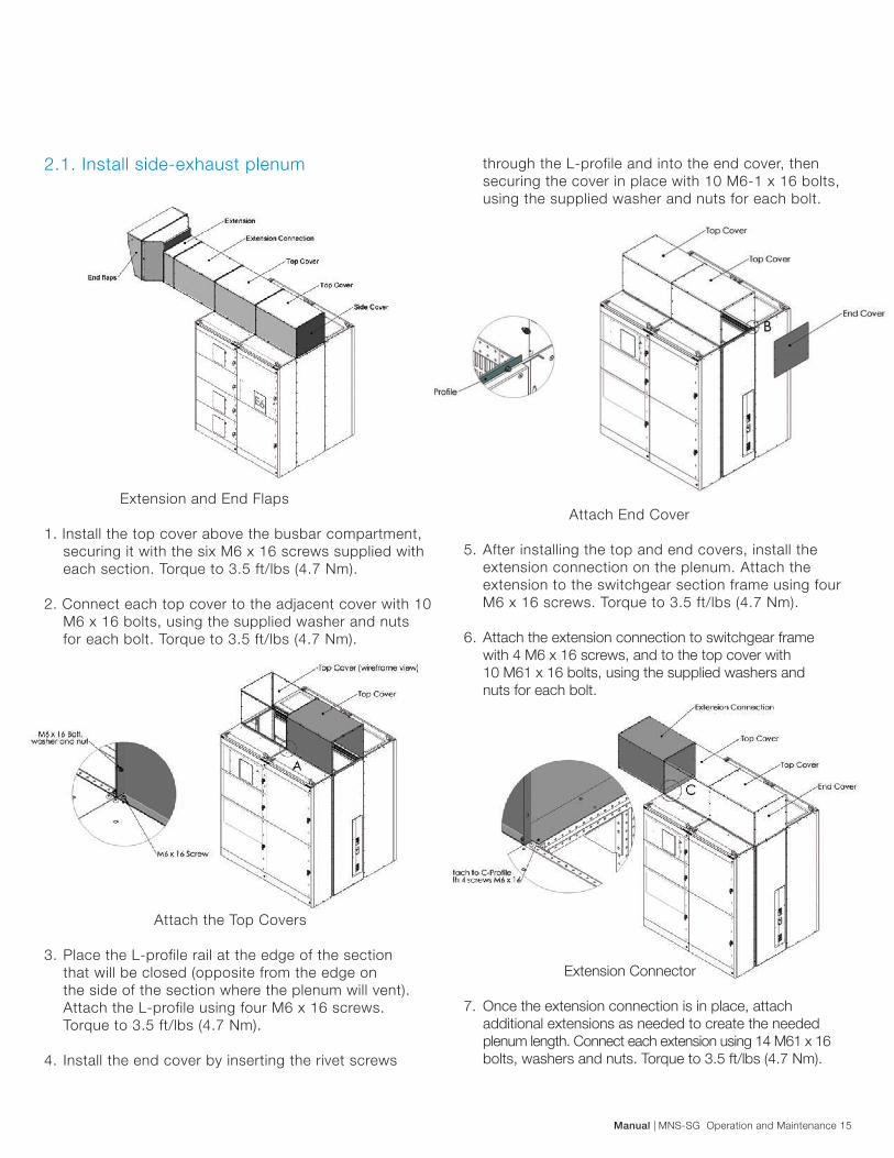
through the L-profile and into the end cover, then securing the cover in place with 10 M6-1 x 16 bolts, using the supplied washer and nuts for each bolt.
Attach End Cover
5. After installing the top and end covers, install the extension connection on the plenum. Attach the extension to the switchgear section frame using four M6 x 16 screws. Torque to 3.5 ft/lbs (4.7 Nm).
6. Attach the extension connection to switchgear frame with 4 M6 x 16 screws, and to the top cover with 10 M61 x 16 bolts, using the supplied washers and nuts for each bolt.
Extension Connector
7. Once the extension connection is in place, attach additional extensions as needed to create the needed plenum length. Connect each extension using 14 M61 x 16 bolts, washers and nuts. Torque to 3.5 ft/lbs (4.7 Nm).
2.1. Install side-exhaust plenum
Extension and End Flaps
1. Install the top cover above the busbar compartment, securing it with the six M6 x 16 screws supplied with each section. Torque to 3.5 ft/lbs (4.7 Nm).
2. Connect each top cover to the adjacent cover with 10 M6 x 16 bolts, using the supplied washer and nuts for each bolt. Torque to 3.5 ft/lbs (4.7 Nm).
Attach the Top Covers
3. Place the L-profile rail at the edge of the section that will be closed (opposite from the edge on the side of the section where the plenum will vent). Attach the L-profile using four M6 x 16 screws. Torque to 3.5 ft/lbs (4.7 Nm).
4. Install the end cover by inserting the rivet screws

16 MNS-SG Operation and Maintenance | Manual
Top Cover – Rear Exhaust
3. Install the top covers over each cable compartment of the lineup securing them with the six M6 x 16 screws supplied with each section. Torque to 3.5 ft/ lbs (4.7Nm).
Install Top Covers
4. Connect each top cover to the adjacent cover with 10 M61 x 16 bolts, using the supplied washer and nuts for each bolt. Torque to 3.5 ft/lbs (4.7 Nm).
8. Attach the end flaps to extension on the opposite side of the wall from the switchgear, outside the vent hole. Connect the end flaps using 14 M6-1x16 bolts, washers and nuts. Torque to 3.5 ft/lbs (4.7 Nm). 2.2. Install rear-exhaust plenum
Rear Exhaust Plenum
The preferred location for the rear-exhaust plenum is the middle of the lineup, but it can be placed in any part of the lineup.
1. Remove the top covers of busbar and cable compartments where the plenum will be attached.
2. Install the top cover on the section where the rear exhaust will vent from the lineup. This cover is the same as the others, but the back side is removed to allow the gas to flow out of the lineup.

Manual | MNS-SG Operation and Maintenance 17
Top Cover – Rear Exhaust
9. Once the extension connection is in place, attach additional extensions as needed to create the needed plenum length. Connect each extension using 14 M61 x 16 bolts, washers and nuts. [Torque to 3.5 ft/ lbs (4.7 Nm).] 10. Attach the end flaps to connect the plenum to the exterior vent hole. Connect the end flaps using 14 M61x16 bolts, washers and nuts. [Torque to 3.5 ft/lbs (4.7 Nm)].
End Flaps
5. Place the L-profile rail at the side-edge of the section that will be closed. Attach the L-profile using four M6 x 16 screws. Torque to 3.5 ft/lbs (4.7 Nm).
Top Cover – Rear Exhaust
6. Install the rear cover on top of the cable compartment using 10 M6-1 x16 bolts, washers and nuts. Torque to 3.5 ft/lbs (4.7 Nm). 7. If the lifting angles are still in place, remove the angles that interfere with the cover(s) and replace the bolts.
Note: For 31.5 in (800 mm) or 39.4 in (1,000 mm) wide sections, install a rear-plenum transition to compensate for the width difference to the rear extension.
8. Attach the extension connection to switchgear frame with four M6 x 16 screws, and to the top cover with 10 M61 x 16 bolts, using the supplied washers and nuts for each bolt. Torque all to 3.5 ft/lbs (4.7 Nm).
DO NOT remove the top cover of cable compartment section that has the rear cover attached to it.

18 MNS-SG Operation and Maintenance | Manual
2.3. Positioning arc-resistant switchgear
When installing this switchgear, you must provide the following clearances:
- The switchgear must be at least three feet from the walls to either side and behind the switchgear.- There must be at least 4.0 in (100 mm) clearance around the plenum and extensions.- The plenum must direct the exhaust outside of the building. - Designate a safe area adjacent to the outlet from the plenum. This safe area must be 6.0 X 6.0 ft (1.8 X 1.8 m), clearly marked as a Keep Out or restricted area. Do not store equipment or materials in this area that could be damaged by a blast force or heat.- Allow at least 15.0 in (400 mm) between nearest objects or adjacent wall and the end flaps of the plenum.
Safe Area – Front View
Safe Area – Top View
Safe Area-Interior – Front View

Manual | MNS-SG Operation and Maintenance 19
3. Packaging and handling
3.1. Standard packaging
MNS-products are shipped either in single cubicles or in shipping units not exceeding 1.8 m for MNS UL Switchgear in length depending on the type of equipment installed and on the space available for handing the unit at the erection site.
lf no special instructions are given by the customer, packing is carried out based on this document and a suitable method of shipping is selected.
Maximum size of a shipping unit (length x width x height) in mm:
Packed in crate for one section from 600mm up to1000mm - 83 in x 51 in x 101 in 2107mm x 1292mm x 2576mm for 1852mm depth - 90 in x 51 in x 101 in (2307mm x 1292mm x 2576mm) for 2052mm depthPacked in crate for two sections up to 1400mm - 83 in x 63 in x 101 in (2107mm x 1608mm x 2576mm) for 1852mm depth - 90 in x 63 in x 101 in (2307mm x 1608mm x 2576mm) for 2052mm depthPacked in crate for three sections up to 1800mm - 83 in x 79 in x 101 in (2107mm x 2000mm x 2576mm) for 1852mm depth - 90 in x 79 in x 101 in (2307mm x 2000mm x 2576mm) for 2052mm depth
Maximum size of a shipping unit (length x width):
Pallet dimensions for 1852 depth: - 83 in x 51 in (2107mm x 1292mm) - 83 in x 63 in (2107mm x 1608mm) - 83 in x 79 in (2107mm x 2000mm)
Pallet dimensions for 2052 depth: - 90 in x 51 in (2307mm x 1292mm) - 90 in x 63 in (2307mm x 1608mm) - 90 in x 79 in (2307mm x 2000mm)
Shipping pallet dimensions.Approximate values for weights per cubicle
20 MNS-SG Operation and Maintenance | Manual
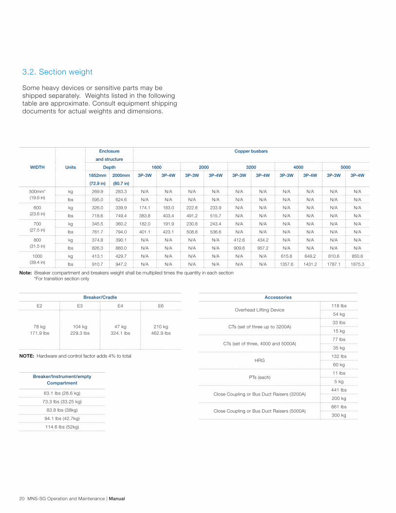
Note: Breaker compartment and breakers weight shall be multiplied times the quantity in each section *For transition section only
NOTE: Hardware and control factor adds 4% to total
Breaker/Cradle
E2 E3 E4 E6
78 kg171.9 lbs
104 kg229.3 lbs
47 kg324.1 lbs
210 kg462.9 lbs
Breaker/Instrument/emptyCompartment
63.1 lbs (28.6 kg)
73.3 lbs (33.25 kg)
83.8 lbs (38kg)
94.1 lbs (42.7kg)
114.6 lbs (52kg)
Accessories
Overhead Lifting Device118 lbs
54 kg
CTs (set of three up to 3200A)33 lbs
15 kg
CTs (set of three, 4000 and 5000A)77 lbs
35 kg
HRG132 lbs
60 kg
PTs (each)11 lbs
5 kg
Close Coupling or Bus Duct Raisers (3200A)441 lbs
200 kg
Close Coupling or Bus Duct Raisers (5000A)661 lbs
300 kg
WIDTH Units
Enclosure
and structure
Copper busbars
Depth 1600 2000 3200 4000 5000
1852mm
(72.9 in)
2000mm
(80.7 in)
3P-3W 3P-4W 3P-3W 3P-4W 3P-3W 3P-4W 3P-3W 3P-4W 3P-3W 3P-4W
500mm* (19.6 in)
kg 269.9 283.3 N/A N/A N/A N/A N/A N/A N/A N/A N/A N/A
lbs 595.0 624.6 N/A N/A N/A N/A N/A N/A N/A N/A N/A N/A
600 (23.6 in)
kg 326.0 339.9 174.1 183.0 222.8 233.9 N/A N/A N/A N/A N/A N/A
lbs 718.6 749.4 383.8 403.4 491.2 515.7 N/A N/A N/A N/A N/A N/A
700 (27.5 in)
kg 345.5 360.2 182.0 191.9 230.8 243.4 N/A N/A N/A N/A N/A N/A
lbs 761.7 794.0 401.1 423.1 508.8 536.6 N/A N/A N/A N/A N/A N/A
800 (31.5 in)
kg 374.8 390.1 N/A N/A N/A N/A 412.6 434.2 N/A N/A N/A N/A
lbs 826.3 860.0 N/A N/A N/A N/A 909.6 957.2 N/A N/A N/A N/A
1000 (39.4 in)
kg 413.1 429.7 N/A N/A N/A N/A N/A N/A 615.8 649.2 810.6 850.6
lbs 910.7 947.2 N/A N/A N/A N/A N/A N/A 1357.6 1431.2 1787.1 1875.3
3.2. Section weight
Some heavy devices or sensitive parts may be shipped separately. Weights listed in the following table are approximate. Consult equipment shipping documents for actual weights and dimensions.

Manual | MNS-SG Operation and Maintenance 21
3.3. Receiving
Before shipment, each vertical section was inspected and marked with its assembly number and location within the lineup. See Section and Device Numbering. Check the equipment received against the packing list to ensure that all components were received. Notify your ABB representative and the carrier at once if there are any discrepancies between what was ordered and what was received.
Before accepting your switchgear, inspect each shipping split and its packaging for evidence of damage during shipment. If there is any evidence the equipment has been damaged or mishandled, a qualified technician should perform a complete inspection of both the interior and exterior of the equipment. If there is damage from improper handling, file a claim for damages at once with the carrier and notify an ABB representative.
Retain all of the packing material until you are confident that you have all components and that they are suitable for installation.
If there will be a delay in installing the switchgear, retain the necessary packing materials to store it safely. See Temporary Storage.
3.4. Unload and move switchgear components
Unload the sections or shipping splits as close to the installation site as possible to minimize additional transportation. Place the shipping splits on a flat surface. When moving the sections or shipping splits, keep them vertical at all times.
Sections and shipping splits usually have a high center of gravity. To improve stability while moving them to the installation site, leave the sections or shipping splits secured to the shipping skid or base.
Note: Never set the switchgear sections on edge. To prevent deformation, sections should always rest flat on the floor or supporting structure.
Be sure to balance your loads carefully when moving them and use safety straps when using material-handling equipment.
The switchgear includes very heavy components. To prevent equipment damage and serious injury or death, only use material-handling equipment with sufficient capacity for the loads involved. Components should be unloaded and transported only by qualified operators and/or installers.
Accessories
Overhead Lifting Device118 lbs
54 kg
CTs (set of three up to 3200A)33 lbs
15 kg
CTs (set of three, 4000 and 5000A)77 lbs
35 kg
HRG132 lbs
60 kg
PTs (each)11 lbs
5 kg
Close Coupling or Bus Duct Raisers (3200A)441 lbs
200 kg
Close Coupling or Bus Duct Raisers (5000A)661 lbs
300 kg
WIDTH Units
Enclosure
and structure
Copper busbars
Depth 1600 2000 3200 4000 5000
1852mm
(72.9 in)
2000mm
(80.7 in)
3P-3W 3P-4W 3P-3W 3P-4W 3P-3W 3P-4W 3P-3W 3P-4W 3P-3W 3P-4W
500mm* (19.6 in)
kg 269.9 283.3 N/A N/A N/A N/A N/A N/A N/A N/A N/A N/A
lbs 595.0 624.6 N/A N/A N/A N/A N/A N/A N/A N/A N/A N/A
600 (23.6 in)
kg 326.0 339.9 174.1 183.0 222.8 233.9 N/A N/A N/A N/A N/A N/A
lbs 718.6 749.4 383.8 403.4 491.2 515.7 N/A N/A N/A N/A N/A N/A
700 (27.5 in)
kg 345.5 360.2 182.0 191.9 230.8 243.4 N/A N/A N/A N/A N/A N/A
lbs 761.7 794.0 401.1 423.1 508.8 536.6 N/A N/A N/A N/A N/A N/A
800 (31.5 in)
kg 374.8 390.1 N/A N/A N/A N/A 412.6 434.2 N/A N/A N/A N/A
lbs 826.3 860.0 N/A N/A N/A N/A 909.6 957.2 N/A N/A N/A N/A
1000 (39.4 in)
kg 413.1 429.7 N/A N/A N/A N/A N/A N/A 615.8 649.2 810.6 850.6
lbs 910.7 947.2 N/A N/A N/A N/A N/A N/A 1357.6 1431.2 1787.1 1875.3

22 MNS-SG Operation and Maintenance | Manual
3.4.1. Loading and transport
The truck can be unloaded by crane or fork-lift truck. The loads must be lowered onto a flat surface.
3.4.2. Ground transport
- By fork-lift truck- By lifting and conveying devices- In an emergency, with rollers (min. 3 pieces)- Switchgear cubicles have to be transported only in the vertical position.- Tilting and canting must be avoided
Transport with a hand-pulled truck Fork-lift transport
Crane transport, transport unit unpacked
Roller transport Crane transport, transport unit in box
Cubicles may easily tip over when transported with a hand-pulled truck. Therefore the distance between the wooden cross beam or the pallet and the underground should not be more than 3 mm.

Manual | MNS-SG Operation and Maintenance 23
Arrangement of Lifting Angles
3.4.3. Transport by crane
Sections are equipped with lifting angles to enable unloading and positioning using a crane. Do not fasten any lifting device directly to the vertical sections. Lift only using the lifting angles located on the outer corners of each section. If lifting angles can be removed after the section is in position. If you remove the lifting angles, replace the bolts; do not leave the bolt holes open.
Transportation by crane must comply with the ASME B30 Safety Standards Committee for Cableways, Cranes, Derricks, Hoists, Hooks, Jacks, and Slings.
For transport by crane, the shipping units are equipped with lifting angles.
Shipping units with one, two or three sections are equipped with single angles on each corner of every shipping section.
Sling minimum angle Sling leg angle should not be more than 120°.
Correct hook engagement on lifting eye
- Lift units from the four outside corners- Fastening of any lifting device directly to the frame sections is not permitted.
- When installing the sling hooks, the hook should always be pointing to the outside of the load and not to the center of the load.- The lifting angles may be removed after the switchgear has been erected.
Frame corner joint with lifting angle
Sling placement on SG
Tilting danger signs must not be removed before all cubicles have been secured to the foundation.
Do not put the switchgear down on one edge, because of the danger of considerable mechanical damage.

24 MNS-SG Operation and Maintenance | Manual
3.4.4. Temporary storage
If the switchgear will not be immediately installed upon receipt, it should be stored under the following conditions to avoid damage:
- Unpack immediately upon delivery and inspect for damage. See Receiving. - Open all section doors and allow the equipment to adjust to room temperature and humidity for several hours. - Storage conditions: <50% humidity, 32-104°F (0-40°C). - Connect external power to space heaters (and temporarily disconnect from internal circuitry, if so connected) to help drive off condensation. - If the switchgear will not be installed soon after arrival, cover the sections to protect them.
TIP: You can use heaters or hang a 100 watt incandescent light bulb inside the section to reduce condensation.
If your delivery includes spare parts:
- Store the components indoors in a condensation- free environment, with no more than 50% humidity, with ambient temperature above freezing but not exceeding 104°F (40°C). - Store them with the boxes top-side up.- Store circuit breakers upright in their original shipping carton. Do not stack.

Manual | MNS-SG Operation and Maintenance 25
4. Locate and connect the switchgear
1. Before beginning the installation, ensure that you have all of the needed components:
- Switchgear sections - Fastener hardware to connect sections - Shipping split connection hardware
2. Make a final check that all components are in good condition. If there is any evidence of damage to the equipment, contact an ABB representative to evaluate the condition of the equipment before proceeding with installation.
3. Carefully review all supplied project drawings and notes to familiarize yourself with the layout and construction of the switchgear.
4. Based on the footprint shown on the general arrangement drawings, mark the floor for all drill holes necessary to fasten the switchgear or base frame to the floor, and for cable conduits (if applicable). See Fastening Sections to a Base Frame.
5. Install power and secondary (control) conduits before moving the switchgear to the site. The available space for conduits appears on the floor plans supplied with the switchgear. Conduits should not extend more than 1.0 in (25mm) above floor level.
4.1. Installation location requirements
The installation must meet the following requirements:
- Indoor location protected from moisture and dramatic temperature changes. For longest equipment life, install the switchgear in an enclosed room with temperature and humidity control and filtered, and forced air ventilation. - Level the site, preferably including a base frame that is either embedded in the concrete floor or rests on a false floor on supports. The floor must be straight and level to +/- 1/4 inches (6 mm) over the entire length of the line-up. - Prepare proper openings in the floor, wall and ceiling for cables, conductors, pipes, bars and ventilation in accordance with the construction drawings provided. - At least 2.5 ft (750mm) from the top of the highest section to the ceiling, and at least 3.0 ft (920mm) between the left and right end sections to the walls. - At least 3.5 ft (1066mm) between the unit and the rear wall.
- See Positioning Arc-Resistant Switchgear for special restrictions regarding distances around the switchgear and other positioning requirements.
Clearances – Front View
Clearances – Side View
- For sections with left-mounted doors, provide at least 3.0 ft (920mm) between the left wall and the left-end section so the doors can be opened more than 120°.- Ambient temperature is to be above -13° F (-25° C) but not exceeding 104°F (40°C) at 85% non-condensing humidity.- Supply sufficient space for future expansions, if required.

26 MNS-SG Operation and Maintenance | Manual
- Supporting brackets, beams, enclosures and foundation frames should be painted or treated with corrosion-resistant coating. To facilitate installation and maintenance, the site should also have:- Convenient alignment with other equipment.- Accessibility for maintenance.- Adequate lighting.- Free access to the electrical equipment rooms.
4.2. Installation Guidelines
If the installation is being done near operational equipment, it may be appropriate to erect temporary barriers between that equipment and the switchgear.
If you are adding sections to existing switchgear, turn off all power supplying this equipment before working on or inside it.
Always use an appropriate voltage-sensing device to confirm that the power is off prior to installing or working with the switchgear.
Follow appropriate lockout/tagout procedures.
4.3. Section installation sequence
Sections can be installed or added in any order, and new sections may be added between existing sections. If the sequential order designated during manufacturing is altered onsite by adding sections to an existing lineup, the main bussing must match; and the related drawings must be updated.
When adding, removing or rearranging sections, do not exceed the maximum amperage available on the horizontal bussing.
4.4. Install and connect shipping splits
Note: Diagrams showing the location of fasteners and the appropriate torque values can be found in the Torque Table section of this manual.
4.4.1. Position shipping splits
Remove the shipping splits from their pallets or skids. If you need to support a multiple- section shipping split at the base after removing it from the pallet, use supports at the corner of each section. Don’t support the shipping split only at the four outer corners.
Position the shipping splits in their final arrangement and location. Connecting the sections together before attaching them to the floor and/or wall will simplify splicing the horizontal bus.
If doors won’t close easily or panels are twisted or stressed, this may indicate that the site is not leveled. You may be able to shim the sections to level them.
4.4.2. Connect sections
Note: Use only the provided fasteners to assemble the switchgear. 1. Begin the installation at either the left or the right end of the lineup by connecting the frames of the sections together. The left side of each frame is fitted with threaded inserts. Sections are fitted on the right side with the necessary rivet nuts. Insert the bolts from the left side of one frame to the inserts in the adjoining section to the right.
Frame Connection Using Spacer Bolts
Follow all instructions related to the installation of the switchgear to avoid potentially hazardous situations that could result in serious injury or death.

Manual | MNS-SG Operation and Maintenance 27
Section Frame Connections
2. Connect the sections using the provided hardware, consisting of 12 M8-1.25 x 20. Torque to 15 ft/lbs (20 Nm). The hardware bag is typically affixed to the front of the switchgear shipping split.
3. After connecting the sections, you can attach the lineup to the floor (see below).
4.5. Splice horizontal busbars
Note: The fasteners provided with the switchgear include an integrated thread coating that ensures they will remain at the torque valued. See Eslok® Fasteners in this manual for more.
The bus in each section is designed to allow splicing with the bus of the adjacent sections to create a continuous horizontal bus. The splice links are located on the right-hand side for the neutral and phase A and on the left-hand side for phase B and C of each section. They are slid to the right or left to connect the bus to the adjacent section.
1. After installing and connecting the shipping splits, connect the main horizontal bus splice links and tighten the hardware to the specified torque. Splice kits are supplied from the factory, installed on the right-hand side for neutral and phase A, and left-hand for phase B and C of each shipping split.
Splice Kit

28 MNS-SG Operation and Maintenance | Manual
3. Tighten the four M12 bolts. For easiest installation, use a long ratchet extension that extends outside the front of the wireway and an 18mm socket with a universal joint. Torque to 52 ft/lbs (70 Nm). Use only the fasteners provided for busbar connections. Do not use additional locking fluid. See Eslok® Fasteners in this manual for more information about the fasteners.
4. Once torqued to the proper value, draw a line across each fastener head and the surrounding metal surface so you can visually check whether the fastener has been properly torqued.
Torque Marks
Repeat this process for all of the splice kits, including the neutral bus if provided. You must splice the horizontal ground bus between adjacent sections in the cable compartment. Splice links are provided on the right-hand side of each section for neutral and Phase A, and on the left-hand side for Phases B, C and the ground. The links may be loosened and bridged to the adjacent section.
Note: The holes at the ends of all busbars ensure adequate adjustment within the required tolerances. If the lineup has been installed properly, the busbars in adjacent sections will line up. Never drill or modify busbars if alignment is poor. Ensure that the adjacent sections are properly and completely connected together mechanically before connecting the horizontal bus splices.
2. Loosen the bolts holding the splice link(s) in place and slide the link(s) to straddle the horizontal bus in the adjacent (right/left-hand) section. Carefully position the splice link so that it straddles the bus equally on both the left and right hand sections.
The maximum gap between the left and right busbar is 0.9 in +/- 0.1 (25mm +/- 3).
Busbar Gap
Slide Link to Adjacent Busbar

Manual | MNS-SG Operation and Maintenance 29
Attach the sections using four bolts through the holes in the section base to the floor or base frame. Use M8 (5/16 in) or larger hardware. Torque to 14 ft/lbs (20 Nm).
Floor Mounting Anchor Plan 4.7. Attach overhead lifting device
A traveling, overhead lifting device is available to assist with handling breakers. The front section of the switchgear provides support for the lifting device. The device travels the full width of the switchgear. The breaker lifts from the floor or from a completely withdrawn circuit breaker cradle with a lifting yoke. A worm-gear-driven mechanism and wire rope, operated by a removable hand crank, provide lifting power.
Although the driving mechanism allows for easy hand operation, the weight of the circuit breaker cannot accidentally move the mechanism. See the corresponding ABB drawing for detailed operating instructions.
Do not clean the contact surfaces on new switchgear. For connections to existing switchgear with heavy oxidation, you may clean the contact surfaces of bare copper ground bars by sanding lightly with a fine grain aluminum oxide paper.
Refer to the Torque Table for all tightening torques for horizontal buss bolted connections.
Main Horizontal Busbar Splice Kit
4.6. Attach switchgear to floor
After completing the internal connections, attach the switchgear to its location. Switchgear may be:
- Attached to a base frame that has been secured to the floor (preferred method). - Bolted directly to a concrete floor by setting vertical mounting bolts in the floor.- Bolted to floor channels.- Bolted to a false floor. A minimum floor height of 20.0 in (500 mm) is recommended to accommodate the bending radius of the cables and provide adequate accessibility. The false floor must have a carrying capacity of 20 kN/m2 (2.9 PSI) compression load from top to bottom.

30 MNS-SG Operation and Maintenance | Manual
To attach the lifting device:
1. Remove the carriage stop from one end of the lineup.
Remove Carriage Stop
2. Loosen all rails for the overhead lift device and mount the locator plates. Note that the plates have round bosses that mate with holes in the rails.3. Adjust the rails as required to loosely secure the locator plates in place with the bosses in their mating holes.
Adjust the Rails
4. After mating all locator plates in place with the rails, secure the locator plates and the rails. 5. Position overhead lift device on the tines of forklift.
Raise the overhead lift device up to the rails on the frame.
Raise Lift Device
Align wheels on the front rail and behind the rear rail. Adjust the upper-rear wheel to minimize vertical movement.
Align Wheels
Push the overhead lift device off the forklift onto the rails.

Manual | MNS-SG Operation and Maintenance 31
4.8.1. Install connections – general information
All conduit installations should conform to local codes and be compatible with the NEMA environmental rating of the switchgear. Install conduit away from the ground busbar to avoid possible damage. Position the cable connection to minimize bending and maintain relative vertical alignment to incoming connections.
When installing cable, make sure the temperature is above 32 °F (0 °C) unless the cable is appropriate for installation at lower temperatures.
On every connection, verify the compatibility of wire size, type and stranding for the type of power terminations (lugs or terminals).
Use correct lugs in all applications. Crimp compression lugs with the manufacturer- recommended tools. Properly connect all line and load cables to avoid bolted-fault and equipment damage. (see chart p.32)
Cable support is a metal structure designed to help to support the filed cables connections. These structures are designed to be adjustable in height and depth to the end user preferences.
Use the switchgear electrical schematics provided to verify field wiring connection points.
Tighten any unused bolts.
The SG has the option for top incoming, bottom incoming, bus duct (top or bottom ), and connection to dry transformers (Closed couple connection).
Closed couple connection are available for 3-phase 3-wire and 3-phase 4-wire and designed for dry transformer only. It can be on either side of the SG.
For the neutral there are three options:- UL service entrance.- Bonded neutral to ground.- Neutral separated from ground.
If your installation has top incoming connections: Refer to the elevation drawings shipped with the switchgear to check space availability for incoming cables. Make the connections only after the switchgear is in place, leveled, anchored and the sections joined and spliced.Bring the conduit into the top of the incoming section.
Push Device Off the Forklift
Push the overhead lift device off the forklift onto the rails.
Test the continuous movement of the overhead lift device. If the movement is correct, reinstall the carriage stop bracket.
4.7.1. Operating the overhead lifting device
Observe the following requirements when operating the circuit breaker lifting device:
- The wheels must be properly set on track.- Do not depend upon the drum attachment to support the full breaker weight. Allow 4-5 wraps of wire rope to remain on the drum.- Prevent snarling, kinking or knotting the wire rope.- Lift only circuit breakers.- Do not alter the lifting device or the circuit breaker lifting yoke.- Never walk or stand under a circuit breaker suspended by wire rope.- Do not leave a circuit breaker suspended on the wire rope.
4.8. Connect cable and wiring
Verify that all cables are de-energized prior to installing.

32 MNS-SG Operation and Maintenance | Manual
If the top plate has to be modified for the incoming conduit, remove the lifting angle and top plate to perform the modifications. Do not drill or cut the top plate while still attached to the section. This prevents metal chips from falling into the section, which can cause serious damage to the equipment.
After modification, replace the top plate and lifting angle bolts to guard against dust or dirt from entering from the top. The lifting angle bolts can also be removed and the holes plugged. See Crane Handling in this manual.
Optional bottom plates can be removed for modification.For approximate section base dimensions and ground bus locations, refer to the elevation and floor plan drawings shipped with the switchgear.Lug assemblies
E2 breaker connection table
E3 breaker connection table (1600A and 2500A)
E3 breaker connection table (2000A)
E6 breaker connection table
Section Width
Contt CurrentVertical Runback
CouplingNumber of Lugs
Size of Lug Connector
600
1200 2 x 1/4" x 3" 4 2 x 1/4" x 3"700
800
1000
600
1600 2 x 1/4" x 4" 5 2 x 1/4" x 4"700
800
1000
Section Width
Vertical Runback Number of LugsSize of LugConnector
600
2 x 3/8" x 4" 6 2 x 3/8"x 4"700
800
1000
Vertical RunbackNumber of
LugsSize of LugConnector
6 x 1/4" x 4" 9 6 x 1/4" x 4"
Section Width
Breaker Contt Current Vertical Runback Number of LugsSize of Lug Connector
700
E3
1800 2 x 1/4" x 4" 5 2 x 1/4"x 4"800
1000
700
2500 4 x 1/4"x 4" 7 4 x 1/4" x 4"800
1000
Section Width
Vertical Runback Number of Lugs Size of Lugs
4000 4 x 3/8" x 5" 11 4 x 3/8" x 5"
5000 2 x 1/4" x 5" - 4 x 3/8" x 5 14 2 x 1/4" x 5" - 4 x 3/8" x 5
E4 breaker connection table

Manual | MNS-SG Operation and Maintenance 33
Top and floor cable cutouts
34 MNS-SG Operation and Maintenance | Manual
4.8.5. Connection to external control source (If required)
If an external control source is used, it should be stable and not subject to variations. Consult your ABB representative for minimum VA requirements.Terminals for external control sources will usually be provided in the top or bottom wireway of the first or last section of the lineup. See the switchgear drawings for more details.
4.9. Other installation information
4.9.1. Interruption of installation
If work is interrupted during installation or connection, take appropriate measures to ensure that dust, moisture and foreign objects are not allowed to enter the switchgear enclosures.
Close the section doors whenever installation work stops or is delayed. For interruptions lasting more than one day, you should cover the sections. In damp or humid environments, use heaters to prevent condensation. See TemporaryStorage in this manual for more information.
4.9.2. Surface damage
To extend the life and ensure the safe operation of your switchgear, keep the exterior clean and in good condition.To remove grease or oil on the exterior, use a cleaning solvent and a cloth or disposable wipe.See Exterior Metal Damage Repair in this manual for repair instructions.
4.10. Commission the switchgear
4.10.1. Physical equipment check
Check all of the following items related to the installation and site before energizing the switchgear:
- Are the shipping splits connected properly and the lineup firmly attached to the foundation or false floor?- Are shipping split bus splices at all bars tightened to the proper torque? Refer to the Torque Table in this manual.- Are all factory-installed splice connections still at the proper torque as indicated by the alignment of the
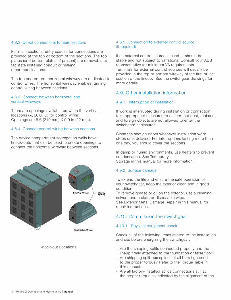
4.8.2. Direct connections to main sections
For main sections, entry spaces for connections are provided at the top or bottom of the sections. The top plates (and bottom plates, if present) are removable to facilitate installing conduit or making other modifications.
The top and bottom horizontal wireway are dedicated to control wires. The horizontal wireway enables running control wiring between sections.
4.8.3. Connect between horizontal and vertical wireways
There are openings available between the vertical locations (A, B, C, D) for control wiring. Openings are 8.6 (219 mm) X 0.9 in (22 mm).
4.8.4. Connect control wiring between sections
The device compartment segregation walls have knock-outs that can be used to create openings to connect the horizontal wireway between sections.
Knock-out Locations

Manual | MNS-SG Operation and Maintenance 35
- Are all barriers, plates, doors and locks in place?- Are the bottom plates (if used) properly installed?- Are all tools, dirt/debris, shipping/packing materials or other foreign objects removed from inside the switchgear?- Is the equipment properly grounded?- Are the phase sequence and marking correct?- Have all withdrawable breakers been inserted and removed to test interlock?
4.10.2. Prepare to energize switchgear
For arc-resistant switchgear:
Ensure that the flaps on the chimney are closed. These flaps are hinged and can be pushed closed by hand.
Ensure that the flaps on the rear covers/ doors are open. To open the covers, push the flap stopper until it contacts the cover/door.
If the switchgear is equipped with a plenum, ensure that the endflapsareclosedposition.Pushtheflapsclosedbyhandor, if too high to reach, using a pole.
Push to open flaps
Flaps in Open Position
Flaps in Closed Position
Flapstopper
Push toopen flaps
Rear Flaps in Closed Position
Rear Flaps in Open Position
End Flaps in Open Position
End Flaps in Closed Position
Push toClose Flaps

36 MNS-SG Operation and Maintenance | Manual
- Close and latch all doors.- Test electrical insulation resistance. Conduct the test phase-to-phase, phase-to- ground, and when applicable, phase-to-neutral. Conduct the test with all unit - disconnects in the OFF position. If the switchgear is equipped with potential transformers (for metering, etc.) remove the primary fuses prior to performing the test.
Note: When conducting an electrical insulation resistance test, isolate equipment sensitive to high test voltages – such as meters, solid state devices, motor winding heaters and capacitor units. Following successful completion of the test, reconnect all relays, operating voltages, circuits and fuses. 4.10.3. Testing and final inspection
Do not exceed the listed voltages for the voltage class of the equipment under testing. Disconnect the shunt-connected coils such as potential transformers.
Do not test solid-state sensors or relays with high voltage. Disconnect solid-state sensors and relays before applying voltage.
With the switchgear erected, assembled, and connected, do the following:
1. Remove packing and shipping materials.2. Make sure that all internal parts are clean and dry. If moisture is present, dry with moving air and heat.3. To check for damaged insulation, apply potential tests to the primary bus. Potential tests should be conducted phase-to-phase and phase-to-ground.
painted marks on the bolts?
Check all of the following items related to the electrical connections and systems before energizing the switchgear. - Ensure the electrical characteristics of the switchgear (e.g., rated voltage, short circuit current rating, grounding system, etc.) are compatible with the site conditions.- Inspect the withdrawable breaker, following the instructions in the Inspect Units section of this manual.- Inspect the unit contacts, following the instructions in the Inspect Units section of this manual.- Using the proper tool for each connection, verify the tightness of all control and power terminals within the units.- Insert all necessary fuses in the main and auxiliary circuits, verifying that they match the apparatus list and the circuit diagram.- Set to its lowest value the main circuit protective device feeding the switchgear.- Set the units’ protective devices to the specified values.- If present, verify that current transformers are properly connected or short- circuited.- If an external control voltage is present, verify that it is OFF.
Always use properly insulated tools and instruments during commissioning. Short circuit currents in low-voltage switchgear are typically very high. Depending on trip settings, high short circuit currents with long durations can occur.
Disconnect the primary power source during testing.
Follow all codes and regulations related to servicing and installing electrical equipment. Failure to follow these instructions can result in short circuits and electrical arcing.
Manual | MNS-SG Operation and Maintenance 37
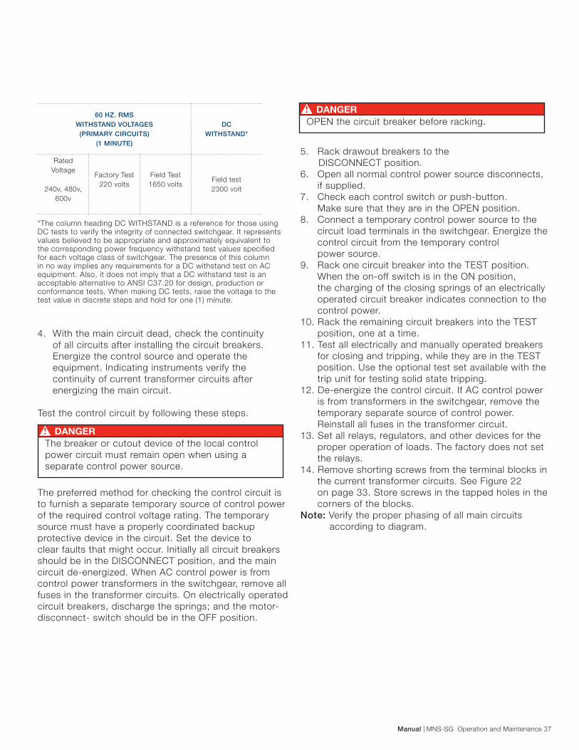
5. Rack drawout breakers to the DISCONNECT position.6. Open all normal control power source disconnects, if supplied.7. Check each control switch or push-button. Make sure that they are in the OPEN position.8. Connect a temporary control power source to the circuit load terminals in the switchgear. Energize the control circuit from the temporary control power source.9. Rack one circuit breaker into the TEST position. When the on-off switch is in the ON position, the charging of the closing springs of an electrically operated circuit breaker indicates connection to the control power.10. Rack the remaining circuit breakers into the TEST position, one at a time.11. Test all electrically and manually operated breakers for closing and tripping, while they are in the TEST position. Use the optional test set available with the trip unit for testing solid state tripping.12. De-energize the control circuit. If AC control power is from transformers in the switchgear, remove the temporary separate source of control power. Reinstall all fuses in the transformer circuit.13. Set all relays, regulators, and other devices for the proper operation of loads. The factory does not set the relays.14. Remove shorting screws from the terminal blocks in the current transformer circuits. See Figure 22 on page 33. Store screws in the tapped holes in the corners of the blocks.Note: Verify the proper phasing of all main circuits according to diagram.
*The column heading DC WITHSTAND is a reference for those using DC tests to verify the integrity of connected switchgear. It represents values believed to be appropriate and approximately equivalent to the corresponding power frequency withstand test values specified for each voltage class of switchgear. The presence of this column in no way implies any requirements for a DC withstand test on AC equipment. Also, it does not imply that a DC withstand test is an acceptable alternative to ANSI C37.20 for design, production or conformance tests. When making DC tests, raise the voltage to the test value in discrete steps and hold for one (1) minute.
4. With the main circuit dead, check the continuity of all circuits after installing the circuit breakers. Energize the control source and operate the equipment. Indicating instruments verify the continuity of current transformer circuits after energizing the main circuit. Test the control circuit by following these steps.
The preferred method for checking the control circuit is to furnish a separate temporary source of control power of the required control voltage rating. The temporary source must have a properly coordinated backup protective device in the circuit. Set the device toclear faults that might occur. Initially all circuit breakers should be in the DISCONNECT position, and the main circuit de-energized. When AC control power is from control power transformers in the switchgear, remove all fuses in the transformer circuits. On electrically operated circuit breakers, discharge the springs; and the motor-disconnect- switch should be in the OFF position.
60 HZ. RMSWITHSTAND VOLTAGES (PRIMARY CIRCUITS)
(1 MINUTE)
DC WITHSTAND*
Rated Voltage
240v, 480v, 600v
Factory Test220 volts
Field Test1650 volts
Field test2300 volt
The breaker or cutout device of the local control power circuit must remain open when using a separate control power source.
OPEN the circuit breaker before racking.

38 MNS-SG Operation and Maintenance | Manual
5. Component operation documents
Circuit breakers, relays and other components may have documentation that describes operating instructions that are not included in this manual. Review any documentation provided with those components prior to operating the switchgear.Review the final project documents, manuals and other documents that accompanied your switchgear regarding operating procedures.
6. Maintenance
A well-planned and executed maintenance program will ensure uptime, extend equipment life and reduce overall costs. Routine maintenance is typically less costly than the emergency repairs and parts typically required in order to correct unexpected equipment failures.
For information on the mechanical and electrical life of components included in the switchgear, refer to the individual product documentation.
ABB offers a range of preventive maintenance services and programs. ABB can also provide ABB-trained expert technicians and give you fast access to OEM parts. Contact your ABB representative for more information.
6.1. Lockout / tagout
The switchgear’s breakers provide the ability to padlock it in the OFF position to prevent changing the status or position. Follow your local authority having jurisdiction and/or facility’s procedures for properly locking out / tagging out equipment during maintenance.
To open the short circuiting device:
1. Make sure that the current transformer secondary circuits are complete. Do not open circuit the secondary of an energized breaker.2. a) Single Ratio – Remove and store the shorting screw. Do not remove the ground screw.2 b) Multi Ratio – Remove the shorting screw. Insert shorting screw according to connection diagram. Do not remove the ground screw. 4.10.4. Energize the switchgear
After completing all of the previous steps related to installation and commissioning, energize the switchgear following these steps:
1. Apply power on the main incoming.2. Verify that the incoming phase sequence is correct.3. Switch on the main disconnect.4. Check the phase sequence of each unit.5. If existing, switch on any external power sources.
4.10.5. Energize the main bus
After completing the control circuit checkout, energize the switchgear main bus.1. Energize the incoming bus to the switchgear main circuit breaker. Observe if operation of instruments and relays is correct.2. Energize the separate control power source, if furnished.3. Energize the switchgear main bus by closing the main circuit breaker. Observe if operation of relays and instruments is correct.4. If applicable, close feeders and tie circuit breakers.5. Verify that all door panel screws are tight.6. Rack all drawout-type circuit breakers to the CONNECTED position.
4.10.6. Final testing
Check that all instrumentation is working properly and the readings are within specifications or reasonable levels.
Check that all instantaneous protections that were turned down during previous testing are reset to their operating positions.
Maintenance work on this equipment should be performed only by qualified personnel wearing proper personal protective equipment.3
Always use an appropriate voltage-sensing device to confirm that the power is off prior to installing or working with the switchgear.

Manual | MNS-SG Operation and Maintenance 39
6.2. Tighten unit control and power terminals
Recommended Interval: Perform annually or based on your local maintenance schedule. Using the proper tool for each connection, verify the tightness of all control and power terminals within the units. While tightening the terminals, be alert for any signs of heat damage, which indicates potential problems or loose connections. Heat generated by inadequate terminal torque is one of the leading causes of equipment malfunction and failure. When heat damage is observed, it typically indicates damage to the component. Repair or replacement may be required.
6.3. Remove/insert withdrawable breaker
For information on how to remove or insert a breaker, reference the specific instructions regarding breakers in document 1SDH000533R0002, Emax UL Listed Breaker Installation, Service and Maintenance Instructions.
You may need to withdraw or remove a breaker for repair, update or testing. The switchgear allows breaker units to be easily replaced with breakers of the same rating.
You may continue to operate the switchgear with a unit removed. However, if the breaker will be removed for an extended period of time, it is advisable to replace it with another breaker or to temporarily cover the hole where it was with a blank cover.
6.4. Inspect units
Inspect each unit prior to first installation and periodically according to your local maintenance schedule.
Visually inspect the contacts for damage. Look for excessive wear or damage (e.g., worn silver or tin layer, signs of excessive heat, etc.) on all contact surfaces, including distribution bars, withdrawable breakers, power cable connection unit, etc. See breaker user manual for proper inspection.
Using the proper tool for each connection, verify the tightness of all control and power terminals within the units.
Be sure that the contacts are properly greased. If they appear dry, use a brush to apply the appropriate amount of contact grease. Each unit will require approximately 3.5g of lubricant. Grease both the incoming and outgoing contacts.
If you detect contact damage, we recommend replacing the entire withdrawable unit chassis or the entire contact system. Contact your ABB representative for assistance with repair or replacement.
Forequipmentthatisarc-resistant,ensurethatflapsonthereardoorsorcoversareopenandchimneyflapsareclosed. See Prepare to Energize Switchgear in this manual.
6.5. Inspect busbars
Changes in environmental conditions can cause the busbar mounting components to loosen over time. During scheduled inspections, check the condition of the busbar system in locations where it is possible to access them. The components that can be removed to provide busbar access include the rear panels, side walls, segregation barrier between the cable compartment and main busbar compartment, and the roof plates. 6.6. Exterior metal damage repair
Any scratches or damage to the surface of the vertical sections must be repaired in order to avoid oxidation, which can reduce the life of the equipment.
6.7. Maintenance schedule
It is highly recommended that you establish a periodic maintenance program for the switchgear. The frequency of maintenance activities depends on equipment usage and the operating environment.
Perform a visual inspection, front and rear, to see that there is no evidence of loose parts, warping or undue vibration. Take steps to remedy any deficiencies of this nature that may appear. Keep the assembly dry. Cover to prevent moisture from dripping on the equipment. Do not block vents.
While equipment is energized, always cover live partsto avoid unintentional contact.
Never grease the contacts while the unit is energized

40 MNS-SG Operation and Maintenance | Manual Manual | MNS-SG Operation and Maintenance 40
Compressed dry-air is useful with inaccessible areas.- Remove covers of all panel devices where possible. Check wiring for secure connections. Clean contacts on relays and switches wherever necessary. Replace covers.- Inspect the gearing of the overhead lifting device when used. Keep well lubricated. In very dirty or gritty conditions, use a dry lubricant.- Follow the recommendations of any individual device instructions furnished for maintenance of the device.
6.7.3. 18-to-36 month inspection
Perform the following at 18-to-36 month intervals or sooner if required by local conditions or regulations.
- Clean the circuit breaker stationary primary contacts. See document 1SDH000533R0002 Emax UL Listed Breaker Installation, Service and Maintenance Instructions. Inspect for evidence of excessive heat, arcing, or corrosion.- Inspect secondary wiring bundles for signs of discoloration because of heat or chafing. Check for cracked or embrittled insulation. Replace wire whenever doubtful.- Inspect primary insulation system for accumulated contamination. Clean insulation with a dry cloth, dry-air, vacuum or, if necessary, with an OSHA- approved solvent.- Check the calibration of protective relays approximately every two years.
6.7.4. 10-year maximum inspection
- Disassemble, inspect, clean, lubricate, adjust, and calibrate circuit breaker mechanisms.- Tighten all secondary control wire connections. Check for loose lug crimps and broken wire strands.
6.7.5. Eslok® fasteners
The Eslok® fasteners provided with the switchgear include an integrated, dry, polyamide- based, securing-varnish, thread-coating that ensures they will remain at the torqued valued. Any other polyamide product of same quality characteristic can be used. Do not use additional locking fluid.
6.7.1. Semi-annual inspection
At least twice yearly, perform a thorough inspection of the switchgear. Emphasize the following checks:
- Perform an overall visual inspection.- Check all indicators, meters and instruments for proper operation.- Make sure all bolted panels are secure.- Verify operation of heaters and thermostats, if used.- Check for undue noise or vibration that might loosen bolted connections.- Look for evidence of moisture in the switchgear.
6.7.2. Annual inspection
- Bolted connections should be tight. Discoloration, excessive corrosion, embrittled or discolored insulation may indicate an overheated connection.- Inspect all cables for tight connections and ample support.- Inspect control wiring for signs of wear and damage. Replace wires wherever doubtful.- Examine resistors and other devices prone to overheating.- Open all hinged panels and remove all bolted panels.- Clean insulation thoroughly.- Withdraw and clean all drawout components.- Clean the stationary portion of the switchgear by wiping with a clean cloth.
There are hazards of electrical shocks and/or burns whenever working in or around electrical equipment. Turn off power ahead of the switchgear before performing any maintenance operations. Check incoming line terminals to verify that the equipment is de- energized. Check the out-going terminals to make sure that no feedback conditions exist.
Limit the use of solvents to removing grease and contamination from primary conductors, insulation, and from unpainted metallic surfaces. Do not use alcohol or Freon. Use OSHA-approved solvents in accordance with local regulations. Use a non-flammable solvent with a threshold limit of 300 PPM or higher. Use solvents in well-ventilated areas.

Manual | MNS-SG Operation and Maintenance 41
installation site. This information helps to identify the presence of a potential flash hazard and provides guidance in determining necessary personal protective equipment (PPE) to be worn by installation and maintenance personnel.
You must establish field marking requirements based upon:
- Level of onsite personnel safety training.- Level of required clothing and required PPE.- Consistency for the level of marking for various equipment types, for example: switchboards, panelboards, industrial control panels and MCCs.- Available flash energy on each piece of equipment as determined by available fault current and arc flash duration based on the type and degree of short circuit protection equipment.
7. Additional resources
In addition to this manual, refer to the job-specific literature, manuals and drawings that will provide useful information as you install, operate and maintain the switchgear.
8. Torque fasteners
The Eslok® fasteners provided include an integrated thread coating that ensures they will remain at the torqued valued.
Once torqued to the proper value, draw a line across the fastener head and the surrounding metal surface so you can visually check whether the fastener has changed position and may require attention. Bolts torqued at the factory will be marked in the same way.
The following torque tables apply to horizontal and vertical busbar screw connections, electrical component screw connections, terminal connections and structural components of the MNS-SG system.
Note: For equipment connections and mountings, see the manufacturers’ technical data sheets.
Bus connections are maintenance-free and do not require routine inspections. The fasteners can be re-torqued as many as 10 times and still offering sufficient thread locking effect.
6.8. Arc flash protection
The National Fire Protection Association (NFPA 70E) flash protection marking requirement1
applies to personnel who install, maintain, or repair electrical systems.
(1 Standard for Electrical Safety Requirements for Employee Workplaces.)
NEC Article 110.16 Flash Protection: Switchboards, panelboards, industrial control panels, and switchgears that are in other than dwelling occupancies and are likely to require examination, adjustment, servicing, or maintenance while energized shall be field marked to warn qualified persons of potential electric arc flash hazards. The marking shall be located so as to be clearly visible to qualified persons before examination, adjustment, servicing, or maintenance of the equipment.
FPN No. 1: NFPA 70E-2000, Electrical Safety Requirements for Employee Workplaces, provides assistance in determining severity of potential exposure, planning safe work practices, and selecting personal protective equipment.
FPN No. 2: ANSI Z535.4-1998, Product Safety Signs and Labels, provides guidelines for the design of safety signs and labels for application to products.
The flash criteria are regularly updated as the technology changes. The latest editions of the NEC and NFPA 70E should be used in establishing potential electric arc flash hazards and arc flash marking.
The required flash protection marking is to be applied by the switchgear end-user for each installation. It is similar to other NEC marking requirements such as voltage, voltage hazard labels, and circuits.Flash protection markings, however, must be based on application information and calculations from the
Heat generated by improper terminal torque is a leading cause of equipment failure. Torque terminals to the values shown below
Defects or deficiencies in any electrical equipment should be remedied immediately. If immediate repair is not possible, lockout/tagout the equipment until after repairs have been made or the components replaced.
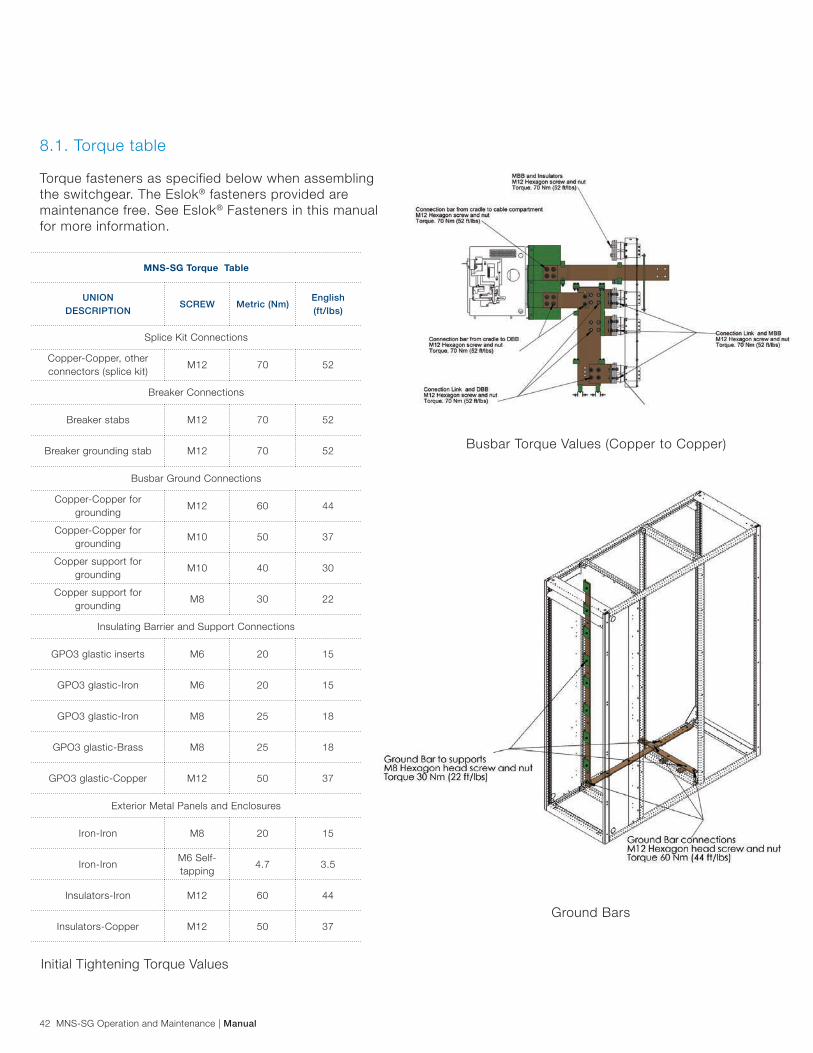
42 MNS-SG Operation and Maintenance | Manual
8.1. Torque table
Torque fasteners as specified below when assembling the switchgear. The Eslok® fasteners provided are maintenance free. See Eslok® Fasteners in this manual for more information.
MNS-SG Torque Table
UNION DESCRIPTION
SCREW Metric (Nm)English (ft/lbs)
Splice Kit Connections
Copper-Copper, other connectors (splice kit)
M12 70 52
Breaker Connections
Breaker stabs M12 70 52
Breaker grounding stab M12 70 52
Busbar Ground Connections
Copper-Copper for grounding
M12 60 44
Copper-Copper for grounding
M10 50 37
Copper support for grounding
M10 40 30
Copper support for grounding
M8 30 22
Insulating Barrier and Support Connections
GPO3 glastic inserts M6 20 15
GPO3 glastic-Iron M6 20 15
GPO3 glastic-Iron M8 25 18
GPO3 glastic-Brass M8 25 18
GPO3 glastic-Copper M12 50 37
Exterior Metal Panels and Enclosures
Iron-Iron M8 20 15
Iron-Iron M6 Self-tapping
4.7 3.5
Insulators-Iron M12 60 44
Insulators-Copper M12 50 37
Initial Tightening Torque Values
Busbar Torque Values (Copper to Copper)
Ground Bars

Manual | MNS-SG Operation and Maintenance 43
Main Busbar Copper-to-Copper Torque
9. Optional accessories
9.1. Maintenance switch Each circuit breaker may be equipped with an optional Maintenance Switch. This two-position selector switch, together with an optional circuit breaker trip unit, trip unit accessories and other components, may be used to select and engage a second, pre-programmed group of trip unit settings. The second group of trip unit settings may be programmed by the user to minimum trip values and engaged temporarily using the Maintenance Switch for enhanced circuit breaker trip unit sensitivity when working on downstream equipment or other associated loads. The Maintenance Switch, together with a provided flashing indicating lamp that warns when the second group of trip unit settings have been engaged, will be installed on the circuit breaker compartment door if space permits. If space does not permit, the switch and indicating lamp will be installed on an adjacent or nearby compartment door.
Frame and Enclosure Fasteners Torque
Main Busbar to Insulation Supports Torque

44 MNS-SG Operation and Maintenance | Manual
10. Disclaimer of warranties and limitation of liability
There are no understandings, agreements, representations or warranties, expressed or implied, including warranties of merchantability or fitness for a particular purpose, other than those specifically set out by an existing contract between the parties.
Any such contract states the entire obligation of seller. The contents of this document shall not become part of or modify any prior or existing agreement, commitment or relationship.
The information, recommendations, descriptions and safety notations in this document are based on ABB experience and judgment with respect to MNS-SG switchgear. This information should not be considered to be all inclusive or covering all contingencies.
No warranties, expressed or implied, including warranties of fitness for a particular purpose or merchantability, or warranties of fitness for a particular purpose or merchantability, or warranties arising from course of dealing or usage of trade are made regarding the information, recommendations, descriptions and safety notations contained herein.
In no event will ABB be responsible to the user in contract, in tort (including negligence), strict liability or otherwise for any special, indirect, incidental or consequential damage or loss whatsoever including but not limited to damage to or loss of use of equipment, plant or power system, cost of capital, loss of profits or revenue, cost of replacement power, additional expenses in the use of existing power facilities, or claims against the user by its customers resulting from the use of information, recommendations, descriptions and safety notations contained herein.

Contact us
2TD
C49
0006
Rev
A E
ffect
ive
06/3
0/20
13 S
ubje
ct t
o ch
ange
with
out
notic
e.USA
ABB, Inc. Low Voltage Products & Systems3700 W Sam Houston Pkwy SHouston, TX 77042 Toll Free: 1 888 385-1221 ABB, Inc. Low Voltage Products & Systems400 Crown Colony Drive, Suite 303 Quincy, MA 02169 www.abb.us/lowvoltage
Canada
ABB, Inc. Low Voltage Products & Systems2117 - 32e Avenue Lachine, QC H8T 3J1 Tel.: 1 514 420-3100 Toll Free: 1 800 567-0283 Fax: 1 514 420-3137 [email protected] ABB, Inc. Low Voltage Products & Systems201 Westcreek Blvd. Brampton, ON L6T 5S6 Tel.: 1 905 460-3000 Fax: 1 905 460-3395 ABB, Inc. Low Voltage Products & Systems110, 4411-6th Avenue S.E. Calgary, AB T2G 4E8 Tel.: 1 403 278-7111Fax: 1 403 278-8232
www.abb.ca/lowvoltage
Mexico
ABB Mexico, S.A. de CV.Low Voltage SystemsAv. Central No. 405, Parque LogisticoC.P. 78395, San Luis Potosi, SLPTel.: +52 444 8708 000
While all care has been taken to ensure that the information contained in this publication is correct, no responsibility can be accepted for any inaccuracy. The Company reserves the right to alter or modify the information contained herein at any time in the light of technical or other developments. Technical specifications are valid under normal operating conditions only. The Company does not accept any responsibility for any misuse of the product and cannot be held liable for indirect or consequential damages.
©Copyright 2013 ABB Inc. All rights reserved


![INDEX [] and Machinery... · ansi standard 1792–1816 ... ansi b4.2 642, 644, 646, 648–655, 657. index 2559 ansi b4.4m 656 ansi b47.1 1882 ansi b5.18 920, 922–924 ansi b6. 7](https://static.fdocuments.net/doc/165x107/5aa7faa47f8b9aee748cbd3f/index-and-machineryansi-standard-17921816-ansi-b42-642-644-646.jpg)