OPERATION AND MAINTENANCE MANUAL fervi
20
OPERATION AND MAINTENANCE MANUAL Hand-held digital hardness tester Art. D008 ORIGINAL INSTRUCTIONS fervi.com
Transcript of OPERATION AND MAINTENANCE MANUAL fervi

OPERATION AND
MAINTENANCE MANUAL
Hand-held digital hardness tester
Art. D008
ORIGINAL INSTRUCTIONS
fervi.
com

MEASURINGINSTRUMENTS
Page 2 of 20
FOREWORD
Read this manual before operating any machinery
ORIGINAL INSTRUCTIONS
Before starting any operation it is compulsory to read this instruction manual. The guaranteeof smooth operation and full performance of the instrument is highly dependent on theapplication of all the instructions contained in this manual.
Operator Qualification
The workers responsible for using this tool must have all the necessary information,education and receive adequate training regarding safety, including:a) The conditions of use of the equipment;b) Foreseeable abnormal situations, pursuant to Article 73 of Legislative Decree81/08.
We guarantee the instrument complies with the specifications and technical
instructions described in the Manual on the date of its issuance (shown in this page).
On the other hand, the instrument may also be subject to important technical changes
in the future, without the manual being updated.
Therefore, see FERVI for information about modifications that could be implemented.
REV. 2 December 2013
fervi.
com

MEASURINGINSTRUMENTS
Page 3 of 20
1 GENERAL SAFETY INSTRUCTIONS
1. Periodically check the state of the sensor connection cable.
2. Never disassemble or modify any part of the hand-held hardness tester.
3. Do not use the hand-held hardness tester in places at risk of fire or explosion.
4. Do not use the hand-held hardness tester in damp or wet environments.
5. Do not use the hand-held hardness tester outdoors, exposed to the effects of theweather.
6. Keep unqualified people, children, etc. away from the work environment where thehand-held hardness tester is used.
7. Do not use the cable for purposes other than those envisaged, therefore do not use itto carry or hang up the device.
1.1 Risks Associated with the Work AreaOnly use the hand-held hardness tester with proper lighting and visibility.
Pay particular attention to possible contact with dust or other contaminants that coulddamage the instrument.
It is important to maintain a stable and secure position while working. Be careful not to knockthe sensor of the instrument.
1.2 Technical supportFor any problems or concerns, please contact the retailer from whom you purchased theproduct, who has qualified staff and spare parts.
fervi.
com

MEASURINGINSTRUMENTS
Page 4 of 20
2 CHARACTERISTICS OF THE INSTRUMENT
Automatic conversion between different hardness scales: Correlations betweenHL values and other standard hardness values (Brinell, Vickers, Rockwell and Shore)have been established for 9 of the most commonly used materials. Conversionsbetween different scales can be performed instantly.
Measurements with different inclinations: Measurements can be perform withvarious inclinations. This makes it easy to perform measurements in large and smallspaces.
Automatic cancellation of errors: Measuring accuracy can be compromised, ifincorrect data with an abnormal deviation is accepted. The instrument providesfunctional corrections during normal use and an automatic error cancellation functionduring data analysis.
High testing efficiency: when performing tests that involve testing a large number ofsimilar parts, the ranges of hardness values can be set based on different requirementsto improve the efficiency of the tests. The upper and lower hardness limits can be setfor each type of material.
Printing of data: data can be printed immediately or stored to be printed later.
Communication port RS-232C: data can be transferred to a PC to facilitate datareduction and processing.
Automatic power-off: when the instrument remains inactive for 4 minutes or whenthe battery level is below a critical power level, the instrument will turn offautomatically.
Auto reset: when a sudden change or a drop in voltage occurs, the instrument is ableto automatically reset the data.
LCD screen with backlight.
Intelligent battery recharge management.
Various types of material: hardness tests for steel, cast steel, alloy tool steel, greycast iron, compact cast iron, aluminium alloys, brass, bronze, copper alloys, etc.fer
vi.co
m

MEASURINGINSTRUMENTS
Page 5 of 20
2.1 Technical specifications
Accuracy of measurement: ± 0.8% (750-800 LD)
Measurement ranges:
LD 200 – 900
HB 30 – 655
HRC 20 – 68
HRB 20 – 101.7
HV 80 – 940
HSD 32.5 – 99.5
Operating temperature: 10°C ÷ + 45°C
Relative humidity: < 90% RH
Power supply: 4 rechargeable 1.2 V Ni-MH batteries
Battery recharge time: Approximately 3 hours
Data storage: 255 groups of 9 measurements
Automatic power-off: After 4 minutes of inactivity
Printing paper: Ø 30 x 44 mm
Dimensions: 224 x 84 x 38 mm
Weight: 0.7 Kg (excluding the probe)
2.2 Principles of hardness measurementsThe instrument uses an unusual method for hardness testing, commonly known as impulse orimpact hardness testing. The test is performed by pushing a percussion probe forward withforce so that it hits a part or sample. The probe contains a tip which has the same hardnessas tungsten carbide. The tip is driven by a spring to meet the surface of the test material, onwhich it bounces. The speed of impact and rebound are measured using a permanent magnetand a coil perfectly integrated into the tip of the probe. The movable part of the probe passesthrough the magnet and the coil, in the forward and return stroke, creating an inducedvoltage. The voltages are proportional to the speed, which are directly related to the hardnessof the materials. A very hard material produces a high rebound speed. The voltages or speedsare converted and displayed on the screen as the "L" values of hardness. Correlation betweenthe "L" values and other standard hardness values (Brinell, Vickers, Rockwell and Shore) havebeen demonstrated with the most commonly used materials. Therefore, these values can bedisplayed directly on the screen in hardness scales HRC, HB, HV and HSD.
fervi.
com

MEASURINGINSTRUMENTS
Page 6 of 20
3 DESCRIPTION OF THE INSTRUMENT
3.1 “D” type impact probeThe internal structure of a “D” type probe, the probe employed for the most common uses, isshown schematically in Figure 1
1 Support ring
2 Coil
3 Spherical head of the impact tip
4 Guide tube for the tip
5 Impact tip
6 Tip coupling tube
7 Release button
8 Connection cable
9 Part to be tested
Figure 1 - Overview of theprobe
3.2 Main body of the instrument
Figure 2 - Overview of the main body
1 Printer cover
2 Window to check paper
3 Printer paper outlet
4 LCD screen
5 Power switch
6 Alphanumeric control keys
7 Socket for charging batteries
8 Socket for connecting the probe
9 Communication port RS-232C
fervi.
com

MEASURINGINSTRUMENTS
Page 7 of 20
3.3 LCD screen
1 Battery status signal
2 Material code (type of material)
3Number of measurements andsignal
4 Communication indicator
5 Direction of the test
6 Warning signal
7 Type of probe used
8 Hardness scale used
9 Amount, measured value
10 Upper and lower limit indicators
Figure 3 - Overview of the display
3.4 Alphanumeric control keys
1 Key “0” / screen lighting
2 Key “1” / up “1” / start communication
3 Key “2” / down “1”
4 Key “3” / to obtain average values
5 Key “4” / immediate printing
6 Key “5” / paper feed
7 Key “6” / type of probe selected
8 Key “7” / selection of testing direction
9 Key “8” / type of material tested
10 Key “9” / hardness scale selected
11DATE / TPRT / Inserting the test date /selection for the end of work print out /serial communication activation
12 SAVE / RNG date entry mode
Figure 4 - Overview of the keypad
fervi.
com

MEASURINGINSTRUMENTS
Page 8 of 20
4 USE OF THE INSTRUMENT
4.1 Operation of the probeFirst insert the probe plug into the hardness meter socket, now proceed as follows:
1. Loading (Figure 5.1) Gently slide part No. 6 until the striker is not locked, do notoperate the striker empty, this action can damage it.
2. Positioning (Figure 5.2) Rest the probe on the test material and holding it perpendicularto the workpiece.
3. Execution (Figure 5.3) Press button "7", which will release the striker. Be careful not tomove the probe during the execution of the test.
1 2 3
Figure 5 – Probe operation
4.2 Meter operation
4.2.1 Switching on the instrument
Press the power button located on the left side of the meter. The screen will light up as shownin "Figure 6.1". Approximately two seconds later the screen will appear as in Figure 6.2
1 2
Figure 6 – Switching on the screen
fervi.
com

MEASURINGINSTRUMENTS
Page 9 of 20
4.2.2 Setting the date
Press the DATE button, the two digits on the top line indicate the year, the two digits to theleft, near the bottom, indicate the month and two digits to the right, on the same line,indicate the day, after entering the six digits indicating the date, confirm by pressing theDATE button. Please note the date entered will be cleared when switched off
4.2.3 Insertion of the four conversion factors
After switching on the instrument we can vary four items of data that remain after the lastuse. One or all of the variables can be changed. The four conversion factors are: Selection ofthe sensor type, press the SEN button successively and the following will appear LD – LDC –LD+15 – LC – LE - LG. Selection of the test direction, press the DRC button successively and
arrows will appear as follows . Selection of the material, pressthe MAT button successively and numbers will appear from 1 to 9, which correspond to typesof material as listed on the back of the instrument. Selection of the hardness scale, press theHARD button successively and the following abbreviations of hardness will appear
.
ATTENTION: These four variables can not be arbitrarily chosen, there must be a relationshipbetween the four variables, otherwise the values shown will not be reliable.
4.2.4 Measuring and calculating the arithmetic mean
Once the steps from 4.2.1 to 4.2.3 have been completed, additional measurements can beextracted. After each test, the screen displays the test number (this increases by 1 after eachtest) as well as the hardness values "L" acquired and the converted values.
After performing a group of tests (usually 3 - 5, but more than 15 tests), press the AVGbutton and the letter "A" (average) will appear on the screen. At the same time, on the topline the average value L measured will be displayed and on the bottom line the average valueconverted will be shown. fer
vi.co
m

MEASURINGINSTRUMENTS
Page 10 of 20
4.2.5 Conversion tables
Probe type D +15 L D+15 HRC HRB HB HV HSD
Steel and cast iron300-900
19.3-67.9 80-638 80-937 33.3-99.3
Tool steel 19.8-68.2 80-935
Probe type C L C HRC HRB HB HV HSD
Steel and cast iron 350-960 20-69.5 80-683 80-99631.9-102.3
Probe type E L C HRC HRB HB HV HSD
Steel and cast iron300-880
21.9-70.5 84-656 84-102735.5-102.8
Tool steel 22.2-70.2 83-1009
Probe type G L G HRC HRB HB HV HSD
Steel and cast iron 300-750 47.7-99.9 90-646
Grey cast iron 92-326
Probe type DL L DL HRC HRB HB HV HSD
Steel and cast iron 560-950 20.6-68.2 37.0-99.9 81-646 80-950 30.6-96.8
fervi.
com

MEASURINGINSTRUMENTS
Page 11 of 20
Conversion table applicable to probe types D and DC
No. Materials LD HRC HRBHB
F=30D2 HSD HVb
N/mm2
1Steel
Cast iron(low alloy)
300-900 20.0-68 38.4-99.5 80-647 32.5-99.5 80-940 500-1923
2 Alloy tool steel300-840 20.4-67.1 80-898
3 Stainless steel 300-800 19.6-62.446.5-101.7
85-655 85-802
4 Grey cast iron 400-660 131-387 Without heat treatment
5Nodular cast
iron360-650 90-334 Without heat treatment
6 Cast aluminium 200-560F=10D230-160
7 Brass 200-550 20.0-95.3 40-173
8 Bronze 300-700 60-290
9 *Copper alloys 200-690 45-315
* Including: CuBe, CuCoBe, CuCr, CuNiSi, CuAg, CuAgP, CuCd, CuCdSn, CuMg, CuMn, CuTeP,CuAsP, CuSP, CuSiMn.
4.2.6 Deleting incorrect values
In the event values are given which are not credible or are too high or too low, you canchoose to delete them. After a series of tests (even after pressing the AVG button), it ispossible to press the "1" or "2" buttons to check the values, once they have been located it ispossible repeat the test. The old value will be replaced by the new value. Repeat this processuntil a satisfactory group of values have been obtained. After carrying out the correction,press the "1" button and then the AVG button, the correct average value will appear on thescreen. fer
vi.co
m
MEASURINGINSTRUMENTS
Page 12 of 20
4.2.7 Instant and simultaneous printing
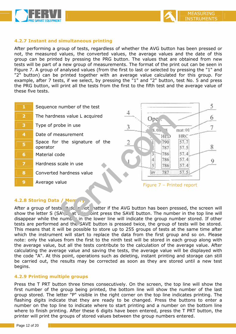
After performing a group of tests, regardless of whether the AVG button has been pressed ornot, the measured values, the converted values, the average values and the date of thisgroup can be printed by pressing the PRG button. The values that are obtained from newtests will be part of a new group of measurements. The format of the print out can be seen inFigure 7. A group of analysed values (from the first to last or selected by pressing the "1" and"2" button) can be printed together with an average value calculated for this group. Forexample, after 7 tests, if we select, by pressing the "1" and "2" button, test No. 5 and pressthe PRG button, will print all the tests from the first to the fifth test and the average value ofthese five tests.
1 Sequence number of the test
2 The hardness value L acquired
3 Type of probe in use
4 Date of measurement
5Space for the signature of theoperator
6 Material code
7 Hardness scale in use
8 Converted hardness value
9 Average valueFigure 7 – Printed report
4.2.8 Storing Data / Memory
After a group of tests, it does not matter if the AVG button has been pressed, the screen willshow the letter S (SAVE) at this point press the SAVE button. The number in the top line willdisappear while the number in the lower line will indicate the group number stored. If othertests are performed and the SAVE button is pressed twice, the group of tests will be stored.This means that it will be possible to store up to 255 groups of tests at the same time afterwhich the instrument will start to replace the data from the first group and so on. Pleasenote: only the values from the first to the ninth test will be stored in each group along withthe average value, but all the tests contribute to the calculation of the average value. Aftercalculating the average value and saving the tests, the average value will be displayed withthe code "A". At this point, operations such as deleting, instant printing and storage can stillbe carried out, the results may be corrected as soon as they are stored until a new testbegins.
4.2.9 Printing multiple groups
Press the T PRT button three times consecutively. On the screen, the top line will show thefirst number of the group being printed, the bottom line will show the number of the lastgroup stored. The letter "P" visible in the right corner on the top line indicates printing. Theflashing digits indicate that they are ready to be changed. Press the buttons to enter anumber on the top line to indicate where to start printing and a number on the bottom linewhere to finish printing. After these 6 digits have been entered, press the T PRT button, theprinter will print the groups of stored values between the group numbers entered.
fervi.
com
MEASURINGINSTRUMENTS
Page 13 of 20
Please note: in order to define the printing range, if group 255 is in the range, the largestnumber must be written on the top line and the smallest number on the bottom line.
The procedures set out from 4.2.4 to 4.2.9 are used for routine testing.
4.2.10 Test processing
After turning the instrument on, enter the date and choose the four conversion factors.
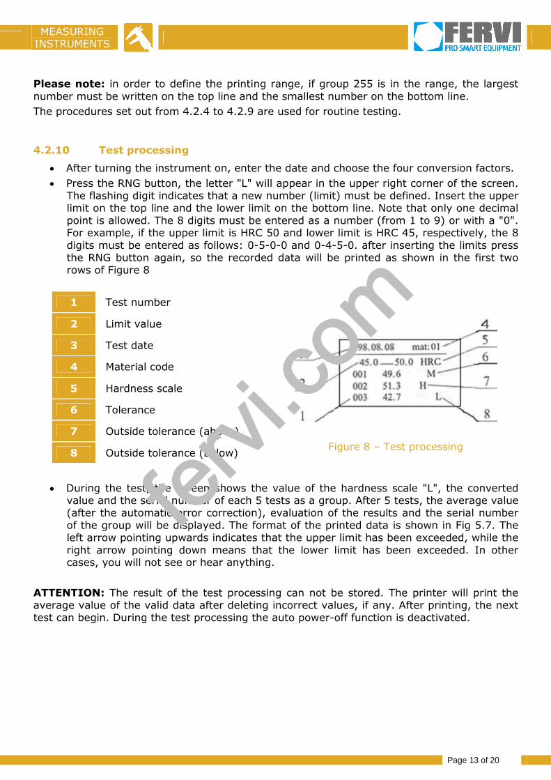
Press the RNG button, the letter "L" will appear in the upper right corner of the screen.The flashing digit indicates that a new number (limit) must be defined. Insert the upperlimit on the top line and the lower limit on the bottom line. Note that only one decimalpoint is allowed. The 8 digits must be entered as a number (from 1 to 9) or with a "0".For example, if the upper limit is HRC 50 and lower limit is HRC 45, respectively, the 8digits must be entered as follows: 0-5-0-0 and 0-4-5-0. after inserting the limits pressthe RNG button again, so the recorded data will be printed as shown in the first tworows of Figure 8
1 Test number
2 Limit value
3 Test date
4 Material code
5 Hardness scale
6 Tolerance
7 Outside tolerance (above)
8 Outside tolerance (below)Figure 8 – Test processing
During the test, the screen shows the value of the hardness scale "L", the convertedvalue and the serial number of each 5 tests as a group. After 5 tests, the average value(after the automatic error correction), evaluation of the results and the serial numberof the group will be displayed. The format of the printed data is shown in Fig 5.7. Theleft arrow pointing upwards indicates that the upper limit has been exceeded, while theright arrow pointing down means that the lower limit has been exceeded. In othercases, you will not see or hear anything.
ATTENTION: The result of the test processing can not be stored. The printer will print theaverage value of the valid data after deleting incorrect values, if any. After printing, the nexttest can begin. During the test processing the auto power-off function is deactivated.
fervi.
com

MEASURINGINSTRUMENTS
Page 14 of 20
4.2.11 Checking the battery power
The battery symbol that is located in the top left corner of the screen indicates the batterystatus.
When the full battery symbol is shown, this means that it is fully charged.
When the half battery symbol is shown, this means that it is not fully charged.
When the empty battery symbol is shown, this means that the battery is low, a alarm willsound to indicate that the battery needs to be charged immediately.
4.2.12 Screen light
When the instrument is switched on the light stays on for 2 seconds, if tests are carried outthe light stays on, if the device stops being used it switches off after 8 seconds, if we want itto stay on, press the "0" button, press the button again and the light will turn off after 8seconds.
4.2.13 Charging the Batteries
Connect the charger plug to the instrument, then plug the battery charger into the 230 V wallsocket. The red light indicates that the battery charger is charging. The charging time isabout 3 hours. When fully charged the green light on the charger will light up and an alarmwill alert you that charging is complete, unplug the battery charger and put it back in its case.
4.2.14 Replacement / insertion of printing paper
a) Remove the printer cover.
b) Remove any remaining paper from the printer.
c) Turn on the instrument, press the FEED button to eject the remaining paper.
d) To install the new roll of paper, cut the two end corners, and insert it into the printerentry slot, press the FEED button to eject the paper.
e) Replace the printer cover.
NOTE: The diameter of the paper should be less than 30mm.
1 Mini printer
2 Printer paper outlet
3 Printer ribbon
4 Printer paper entry slot
5 Printer paper
6The opening direction ofthe printer cover
fervi.
com

MEASURINGINSTRUMENTS
Page 15 of 20
5 CHARACTERISTICS OF THE SAMPLE
The instrument measuring hardness "L" requires the following conditions: dimensions,thickness, roughness, cleanliness and stability.
Dimensions: the mass of the sample, the inertia in the direction of impact must be largeenough.
Thickness: both the thickness and the uniform surface layer must be large enough. Forexample, a layer with a very high degree of hardness can be thin, a layer with mediumhardness must be thick.
Roughness: the surface to be controlled must be smooth enough.
Cleanliness: the surface must not be oiled, rusty, painted, coated and without magneticfields.
Stability: the operator, the workpiece and the the probe must be stationary during the test.
The probe must be perpendicular to the surface to be tested.
Usually the measured values tend to be lower if these conditions are not met.
Type ofprobe used
Weight (kg) Thickness (mm)Homogeneit
yRoughne
ss
CoupledFixed or
heldLocalised
StableSample
SurfaceHardened
ISO Ra (m)
C 0.02-0.5 0.5-1.5 1.5 1 0.2 N5 0.4
D - DC - DLD+15 - E
0.05-2 2-5 5 5 0.8 N7 1.6
G 0.5-5 5-15 15 10 N9 6.3
5.1 Thin samplesThin samples can be controlled if resting on smooth and stable surfaces, between the sampleand the supporting surface there must be a film of oil or petroleum jelly to remove the airbetween the two surfaces.
5.2 Tests on curved surfacesThe radius of curvature of a workpiece to be controlled must not be less than 30mm
fervi.
com
MEASURINGINSTRUMENTS
Page 16 of 20
6 CONNECTION TO A COMPUTER
The RS-232C output of the instrument allows the groups of data stored in the instrument tobe transferred to a PC to be stored and processed (with Windows operating system 95-98).
6.1 Installing the operating system and the hardware connection
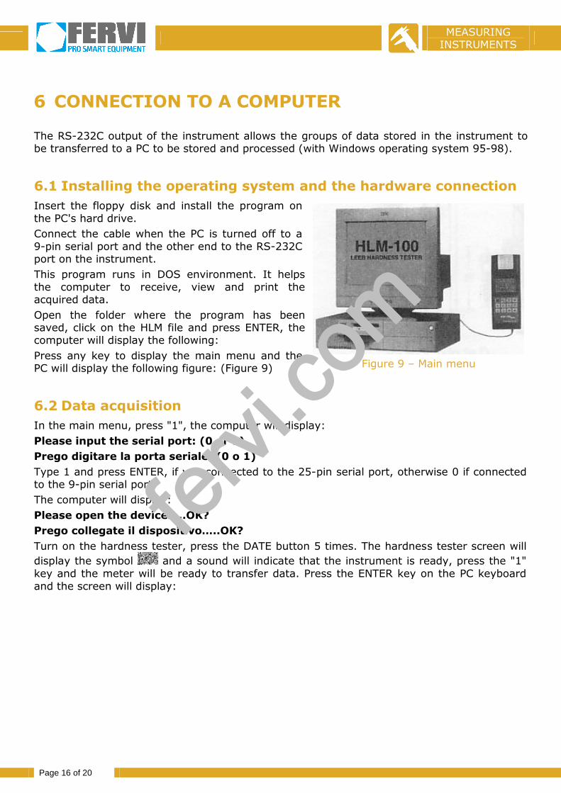
Insert the floppy disk and install the program onthe PC's hard drive.
Connect the cable when the PC is turned off to a9-pin serial port and the other end to the RS-232Cport on the instrument.
This program runs in DOS environment. It helpsthe computer to receive, view and print theacquired data.
Open the folder where the program has beensaved, click on the HLM file and press ENTER, thecomputer will display the following:
Press any key to display the main menu and thePC will display the following figure: (Figure 9) Figure 9 – Main menu
6.2 Data acquisition
In the main menu, press "1", the computer will display:
Please input the serial port: (0 or 1)
Prego digitare la porta seriale: (0 o 1)
Type 1 and press ENTER, if you connected to the 25-pin serial port, otherwise 0 if connectedto the 9-pin serial port.
The computer will display:
Please open the device…..OK?
Prego collegate il dispositivo…..OK?
Turn on the hardness tester, press the DATE button 5 times. The hardness tester screen will
display the symbol and a sound will indicate that the instrument is ready, press the "1"key and the meter will be ready to transfer data. Press the ENTER key on the PC keyboardand the screen will display:
fervi.
com

MEASURINGINSTRUMENTS
Page 17 of 20
Please input the file name to create:
Prego digitate il nome del file da salvare:
Type a name (maximum 8 characters), andpress ENTER, the connection will be enabled andthe computer will display:
Please wait
Prego attendere
Then the screen will show:
Successful
L’operazione ha avuto successo
Press any key to display the data
Premere qualsiasi tasto per visualizzare idati
Press Esc to return to the main menu.
6.3 Display the data from the main menu
From the main menu, type "2" and you will see:
Please input the filename
Prego digitare il nome del file
At this point, enter the name of the file you want to view and press the ENTER key,the computer will display the data, press the up arrow key to display the next page,press the down arrow to display the previous page; press the ESC key to return to themain menu.
If the computer screen displays the message:
Can’t open the file
Non è possibile aprire il file
this means that there is no file with this name.fervi.
com

MEASURINGINSTRUMENTS
Page 18 of 20
6.4 Printing the data
From the main menu, press the "3" key and the computer will display:
Please open the printer first!
Prego collegare la stampante
Please input the filename:
Prego digitare il nome del file:
Please input the start number:
Prego digitare il gruppo di partenza:
Please input the end number:
Prego digitare il gruppo finale:
The number of the initial or final item of data set can be any number between 0 and255. However, the final number must be equal to or larger than the initial number.Otherwise, the computer will display the prompt: “re-enter proper numbers”“reimpostare i numeri appropriati”. After entering the final number, press ENTER, andthe printer will begin. When printing is complete, the screen will display the mainmenu.
High-definition colour printers generally do not support the printing of data.
6.5 Exit the program
From the main menu, press "4" to exit the connection and return to Windows.
fervi.
com

MEASURINGINSTRUMENTS
Page 19 of 20
7 MAINTENANCE AND REPAIRS
7.1 Precautions when recharging batteriesUse the battery charger to power the instrument when printing to prolong the life of thebatteries. When charging the batteries, all the functions of the instrument can still be used.Recharge the batteries at least once a month.
7.2 Impact deviceThe inner surfaces, the guide tube and the support must be kept clean for every test.Lubricants can not be used. When necessary, clean the area in which the striker slides withthe brush supplied. Clean the striker with a cotton ball soaked in alcohol.
7.3 Replacing or refilling the cartridgea. Remove the printer cover and press on the right side of the cartridge marked with the
word "push", raise the right side and carefully pull out the cartridge.
b. Take a new cartridge tighten the ribbon with a finger as indicated by the arrow, passingthe paper between the ribbon and the cartridge, and then insert the right side of thecartridge into the printer and gently insert the left.
c. Replace the printer cover.
7.4 Replacing the batteries
After the batteries have been used for two or three years, they should be replaced:
a: Remove the upper casing of the instrument, detach the connectors of thebatteries.
b: Connect the new battery in series with each other and solder the connectorscorrectly to the instrument, then close the instrument and recharge thebatteries.
NOTE: 1. Replace the used batteries with new Ni-MH brand batteries.
2. Do not install normal batteries.
7.5 Sample for testing hardness
The sample for controlling hardness "L", is certified by the Chinese National Instituteof Metrology. It can be used whenever a sample is needed to check the accuracy ofthe instrument. The striker gradually deteriorates due to improper use and afterextended use. Replace the the probe if it no longer meets acceptable requirements ofaccuracy.
fervi.
com

MEASURINGINSTRUMENTS
Page 20 of 20
7.6 Problems
PROBLEM CAUSE SOLUTION
1. Nothing appears on thescreen
Battery unchargedRecharge the batteries
immediately
Damaged LCD screen Contact Technical Support
2. The screen light will notturn on
The screen is damaged Contact Technical Support
3. The printer does not printthe data
The paper is not insertedproperly
Insert the paper
The printer is malfunctioning Contact Technical Support
4. When the instrument stops working for unknown reasons turn the meter off and onagain to reset the instrument.
If you are unable to solve a problem do not hesitate to contact our Technical Supportcentre.
fervi.
com