
OPERATING MANUAL SERIES SMTBD1 DIGITAL BRUSHLESS SERVO ... · OPERATING MANUAL SERIES SMTBD1...
44
OPERATING MANUAL SERIES SMTBD1 DIGITAL BRUSHLESS SERVO CONTROLLERS (Version 3.1) European version 3.1 .. .. .. This is a general manual describing a series of servo amplifiers having the capability for driving AC Brushless servo motors. It concerns only the basic amplifier version SMT-BD1. The options and other amplifier versions are described in the complementary manuals. This manual may be used in conjunction with appropriate and referenced drawings pertaining to the various specific models. Maintenance procedures should be attempted only by highly skilled technicians (EN 60204.1 standard) using proper test equipment. Read your warranty provision carefully before attempting to adjust or service the unit.
Transcript of OPERATING MANUAL SERIES SMTBD1 DIGITAL BRUSHLESS SERVO ... · OPERATING MANUAL SERIES SMTBD1...

OPERATING MANUAL
SERIES SMTBD1
DIGITAL BRUSHLESS SERVO CONTROLLERS(Version 3.1)
European version 3.1
......
This is a general manual describing a series of servo amplifiers having the capability for driving ACBrushless servo motors. It concerns only the basic amplifier version SMT-BD1. The options andother amplifier versions are described in the complementary manuals. This manual may be used inconjunction with appropriate and referenced drawings pertaining to the various specific models.
Maintenance procedures should be attempted only by highly skilled technicians (EN 60204.1standard) using proper test equipment. Read your warranty provision carefully before attempting toadjust or service the unit.

2
RECEIVING AND HANDLING
Upon delivery of the equipment, inspect the shipping containers and contents for indications ofdamages incurred in transit. If any of the items specified in the bill of lading are damaged, or thequantity is incorrect, do not accept them until the freight or express agent makes an appropriatenotation on your freight bill or express receipt.
Claims for loss or damage in shipment must not be deducted from your invoice, nor shouldpayment be withheld pending adjustment of any such claims.
Store the equipment in a clean, dry area. It is advisable to leave the equipment in its shippingcontainer until ready for use. Each amplifier is checked carefully before shipment. However,upon receipt, the user should make sure that the amplifier received corresponds to or is properlyrated in terms of rated voltage and current for the type of motor which is to be driven. Thedescriptive label affixed to the amplifier specifies electrical ratings.
Infranor Inc. reserves the right to change any information contained in this manual without notice.Infranor Inc. does not assume any responsibilities for any errors that may appear nor for any physical ormaterial damage due to improper handling.
1999 INFRANOR INC.

3
OPERATING MANUAL INFRANOR
SERIES SMTBD1“STANDARD”(March 1999)
1.0.0 GENERAL ............................................................................................................................................ 5
1.1.0 Introduction ....................................................................................................................................... 51.2.0 General description............................................................................................................................. 5
2.0.0 SPECIFICATIONS................................................................................................................................ 7
2.1.0 Technical specifications ...................................................................................................................... 72.1.1 Standard compatibility.......................................................................................................................102.1.2 "CE" Marking ...................................................................................................................................102.2.0 Block diagram...................................................................................................................................112.3.0 Main protections ...............................................................................................................................12
3.0.0 INPUTS / OUTPUTS ...........................................................................................................................13
3.1.0 Connector locations...........................................................................................................................133.2.0 X1 resolver connector (Sub-D 9 points female) .................................................................................143.3.0 X2 position connector (Sub-D 25 points female) ..............................................................................143.4.0 X3 test connector ..............................................................................................................................143.5.0 X4 input - output command connector (Sub-D 25 points male).........................................................153.6.0 X5 serial link (Sub-D 9 points male) .................................................................................................16
4.0.0 CONNECTIONS ..................................................................................................................................17
4.1.0 Connection diagrams .........................................................................................................................174.2.0 Wiring recommendation (according to IEC 801 and EN 55011 standards) ........................................194.2.2 Motor and resolver cables..................................................................................................................19
5.0.0 ADJUSTABLE FUNCTIONS...............................................................................................................20
5.1.0 PC Graphical window (Infranor Digital Drive)...................................................................................205.2.0 Parameter file menu (Files) ................................................................................................................235.3.0 Software configuration menu (Setup) ................................................................................................235.4.0 Advanced functions menu..................................................................................................................235.5.0 Utilities menu ....................................................................................................................................255.6.0 Help Menu ........................................................................................................................................25
6.0.0 COMMISSIONING..............................................................................................................................26
6.1.0 Checking the amplifier configuration..................................................................................................266.2.0 Putting into operation........................................................................................................................266.3.0 Amplifier commissioning and adjustment ...........................................................................................27

4
7.0.0 FAULT FINDING ................................................................................................................................31
7.1.0 System default...................................................................................................................................317.2.0 Stored defaults ..................................................................................................................................317.3.0 Operating problems ...........................................................................................................................337.4.0 Service and maintenance....................................................................................................................34
8.0.0 APPENDIX ..........................................................................................................................................35
8.1.0 Hardware adjustments .......................................................................................................................358.2.0 Resolver connections.........................................................................................................................378.3.0 Motor connections ............................................................................................................................378.4.0 Logic control adjustment ...................................................................................................................408.5.0 BPCW software installation...............................................................................................................42
8.6.0 360o shield on the connectors............................................................................................................44

5
1.0.0 GENERAL
1.1.0 Introduction
Series SMT-BD digital servo modules are PWM servo amplifiers that provide speed control for AC sinusoidalmotors (brushless) with transmitter resolver.
The pluggable SMT-BD1 system is available as a single-axis block version or as a multi-axis version that canreceive up to seven axes in a standard 19" rack including the power supply.
The basic amplifier module SMT-BD1 / A or B provides speed control for AC synchronous motors.
• SMT- BD1 / C version with option card SMT - Ix allows the direct position control of the motor by means ofan incremental position input command (stepping motor emulation).
• SMT- BD1 / D version with option card SMT - Ix allows the direct position control of the motor by means of
an incremental encoder position input command for applications such as electronic gearing. • SMT- BD1 / E version with option card SMT - Ix allows the tension control of a material (thread or film) by
means of an analog tension sensor for winding/unwinding applications master/slave drives. • SMT- BD1 / F version with option card SMT - Ix allows the indexing of a spindle motor axis for tool changes,
according to four programmable positions over one revolution.
• SMT- BD1 / G version with option card SMT - Ix allows product registration function using master/slaveoperation.
• SMT- BD1 / H version with option card SMT - Ix allows all communication with the CAN interface instead of
the + 10V.
The parameter setting software BPCW, which is IBM-PC compatible with the WINDOWS® operating system,allows the display of all amplifier parameters as well as their easy modifications.
1.2.0 General description
SMT-BD1 amplifiers have their own DC/DC converter to provide appropriate logic voltage. This power supplyprovide the bus power voltage of 310 VDC as well as the auxiliary power supply which is necessary particularlywhen the position output information needs to be saved.
Each module is packaged as a 6 U "double Eurocard":
• one power board with IGBT transistors• one logic board with DSP (Digital Signal Processing).
SMT- BD1 amplifier controls directly the motor torque and speed by means of the information provided by atransmitter resolver sensor.
The motor speed or torque input command is an analog command (± 10 V). The motor position is available as twochannels (A and B) and their complements, and one or several marker pulse(s) per revolution.The number of pulses per revolution is programmable. Errors are displayed on the amplifier front panel.
All control parameters are programmable by means of a serial link and saved in a single EEPROM memory. Theauto-configuration and auto-tuning functions allows for easy and quick commissioning of the amplifier.

6
The basic software BPCW, which is IBM-PC compatible with the WINDOWS® operating system, allows thedisplay and modification of all amplifier parameters. The extended version of the BPCW software include thedigital oscilloscope, the simulation function as well as the cogging torque compensation.

7
2.0.0 SPECIFICATIONS
2.1.0 Technical specifications
Operating voltage DC bus 310 VDC (270 V < DC bus < 340 VDC)Auxiliary supply voltage 310 VDC ( 200 V < Uaux < 340 VDC)Motor phase-phase output voltage 200 Vrms for DC bus 310 V
Output currents for the Fusing mode of the I2t protection (see chapter 8.3.3)
AMPLIFIER U rated Imax (A rms)Amplifier max. rated current (Arms)
(Vrms) 1 s WITHOUTFAN*
FAN TYPE1*
FAN TYPE2*
SMT-BD1 - 220/04 240 4,4 2 SMT-BD1 - 220/08 240 8,8 4 SMT-BD1 - 220/12 240 13,8 6 SMT-BD1 - 220/17 240 17,7 8,5 SMT-BD1 - 220/30 240 30,8 10 12 15 SMT-BD1 - 220/30r 240 30,8 10 15 SMT-BD1 - 220/45 240 48,6 10 15 20 SMT-BD1 - 220/45r 240 48,6 10 20 23 SMT-BD1 - 220/60 240 61 10 19 25 SMT-BD1 - 220/60r 240 61 12 26 30 SMT-BD1 - 220/70 240 70 25 30 35 SMT-BD1 - 220/100 240 100 25 30 35
Output currents for the Limiting mode of the I2t protection (see chapter 8.3.3)
AMPLIFIER U rated Imax (Arms)Amplifier continuous current (Arms)
(Vrms) 1 s WITHOUTFAN*
FAN TYPE1*
FAN TYPE2*
SMT-BD1 - 220/04 240 4,4 2 SMT-BD1 - 220/08 240 8,8 4 SMT-BD1 - 220/12 240 13,8 6 SMT-BD1 - 220/17 240 17,7 8,5 8,5 SMT-BD1 - 220/30 240 30,8 8,5 12 15 SMT-BD1 - 220/30r 240 30,8 10 15 SMT-BD1 - 220/45 240 48,6 8,5 15 18 SMT-BD1 - 220/45r 240 48,6 10 20 23 SMT-BD1 - 220/60 240 61 8,5 17 20 SMT-BD1 - 220/60r 240 61 12 26 30 SMT-BD1 - 220/70 240 70 17 30 35 SMT-BD1 - 220/100 240 100 25 30 35
* Maximum ambient temperature = + 40° C, fan 1 = 56 l/s, fan 2 = 90 l/s.
Note: SMT-BD1-X/Xr amplifiers are equipped with an additional heatsink in order to increase the rated current.The width of these amplifiers is then 18 TE instead of 12 TE.

8
PWM Switching frequency 10 KHz
Minimum inductance between phases 1 mH
Current regulator (PI) adjusted to motor
Current loop bandwidth Cut-off frequency for 45° phase shift: > 1 KHz
Internal current limitation Imax: 20% to 100 % Irated: 20% to100 % of Imax
Imax duration = 1 second
External current limitation 0 to 10 V (resolution = 12 bits)100 to 0 % of the internal Imax limitation
Analog speed input command ±10 V, standard resolution = 12 bits and16 bits in option
Motor accel/decel ramp range From 0 to 30 s between zero speed and max. speed
Speed regulator PI2 Sampling period = 0,5 msIntegrator anti-saturation systemAntiresonance filterAdjustable numerical gains
Speed loop bandwidth Cut-off frequency for 45° phase shiftProgrammable : 50 Hz, 75 Hz or 100 Hz
Max. motor speed Adjustable from 100 rpm to 14000 rpm
Speed range 2048 : 1 with 12 bits input command32768 : 1 with 16 bits input command
Encoder position output * Quadrature output A and B channels with n marker pulse(s) per revolution. Programmable
resolution:max. 8192 ppr up to 900 rpmmax. 4096 ppr up to 3600 rpmmax. 1024 ppr up to 14000 rpmAccuracy: 8 arc minutes + ¼ point(2 arc minutes + ¼ point on special request)
Analog outputs (test points) Speed input command (CV): ±10 V for ± max. speed Speed monitor (GT) ±8 V for ±14000 rpm Current input command (IDC): ±10V, DAC OUT 1
8 bits resolution.Current monitor (Imon.): ± 10 V, DAC OUT 2: 8 bits resolution
Logic inputs Enable / Disable: ENABLELimit switch +: FC+Limit switch - : FC-Current command: CIZero speed input command: CV0Reset: RAZ

9
* The total position accuracy must take into account the accuracy of the resolver used

10
Logic outputs Relay contact Umax = 50 V,Imax = 100 mA, Pmax = 10 W• "Amp ready": closed if amplifier OK, open if default• "Power ready": closed if power OK, open if default• IDYN signal: open if I2t threshold is reached
Error display LED on front panel and diagnostic by serial link
Motor and application parameter setting Serial link RS232 (standard) or RS422 / 485 (option)
Automatic functions Amplifier adjustment to the motor(AUTOPHASING)
Automatic regulator tuning (AUTOTUNING) Offset compensation on analog input CV
Electromagnetic compatibility IEC standards 801- 2 - 3 - 4, level 4Conducted and radiated disturbances EN 5011 Group 1, class AElectrical standards for industrial machines N 60204.1: 1500 VAC - 1min insulation
Current leakage >3mA (EMI filters)
Temperature storage - 20° C to + 70° C operation 5° C to +40° C
From 40°C on, the rated currents must be reduced of 3 %/°C.Max. temperature: 50°C
altitude: 1000 m (3300 feet)moisture: < 50 % at 40°C and < 90 % at 20°C
(EN 60204.1 standard)
Cooling Natural convection or forced air, according to the rated current (see current table)
2.1.1 Standard compatibility
SMT-BD1 amplifiers operating either in the RBF rack equipped with the mains filter BF-35/70, or the SMTBM-20A single axis and BF-35, have been approved for their conformity with the Electromagnetic Compatibilitystandards:
• EN 55011, Group 1, Class A (conducted and radiated radioelectric disturbances) • IEC 801 - 2 - 3 - 4 (noise immunity).
Results and test conditions of the LCIE (Laboratories Central des Industries Electriques), which is approved by theEuropean Community, are referenced with n° 416040, 416041, 416042, and 416043.
Results of the tests made according to the Low Voltage directive is referenced in the LCIE report n° 413777.
Standard to be applied to the electrical equipment’s of industrial machines: EN 60204.1.
2.1.2 "CE" Marking
CE recognition marking has been affixed since 1995.

11
2.2.0 Block diagram

12
2.3.0 Main protections
2.3.1 Stored protections
PROTECTION ERROR DISPLAY LED*
Amplifier rated current overload #: I2 t• flashing display = Idyn signal (I2t threshold is reached)• continuous display = amplifier inhibited (I2t default)Resolver cable interruption Resolver
Power stage failure: Power stage• power supply overvoltage• internal switch protection• short-circuit between phasesResolver converter failure R. D. C
Amplifier overtemperature °C Amp
Power supply undervoltage Undervolt.
Motor overtemperature °C Motor
Default of the amplifier parameter storage EEPROM
Amplifier automatic procedure: Busy• flashing display = procedure operating• continuous display = operating error
# The operation mode of the I2t protection is described in chapter 8.3.3.* = LED is unlit; = LED is lit.
Reset of a stored default can be made:
• by means of the RESET function in the BPCW software• via the default RESET input (pin 13 of the X4 connector)• by switching off the amplifier power supply.
2.3.2 Fuse protections
F1 : Control of average DC current of the power board supply.F2 : Control of average DC current of the logic board supply.
AMPLIFIER TYPE F1 F2Power Logic
SMTBD1-220/04 to 12 10 AT 1 A SMTBD1-220/17 to 30 15 AT 1 A SMTBD1-220/45 20 AT 1 A SMTBD1-220/60 SMTBD1-220/70
20 AT40 AT
1 A5 AT
SMTBD1-220/100 40 AT 5 AT

13
3.0.0 INPUTS / OUTPUTS
3.1.0 Connector locations
3.1.1 Front connectors SMTBM-20A single axis block
For more detailed information regarding the power connection, please see the SMTBM-20A manual
3.1.2 RBF rack connectors
For more detailed information regarding the power connection, please see BF Rack manual

14
3.2.0 X1 resolver connector (Sub-D 9 points female)
PIN FUNCTION REMARKS
1 TC (pin H sensor connector) If thermal switch connected to X16 Shield connection If no "360°" connection on the connector2 TC (pin I sensor connector) If thermal switch connected to X17 S1 (pin C sensor connector) MAVILOR motor with resolver3 S3 (pin D sensor connector) MAVILOR motor with resolver8 S4 (pin B sensor connector) MAVILOR motor with resolver4 S2 (pin A sensor connector) MAVILOR motor with resolver9 R2 (pin F sensor connector) MAVILOR motor with resolver5 R1 (pin E sensor connector) MAVILOR motor with resolver
For resolver connections other than the MAVILOR motors, see resolver wiring table in chapter 8.2.0.
3.3.0 X2 position connector (Sub-D 25 points female)
PIN FUNCTION I / O REMARKS
1 Marker Z/ O Differential output of the encoder marker pulse (5 V, 20 mA max.)2 Marker Z O Differential output of the encoder marker pulse3 Channel A/ O Differential output of the encoder channel A/ (5 V, 20 mA max.)4 Channel A O Differential output of the encoder channel A5 Channel B/ O Differential output of the encoder channel B/ (5 V, 20 mA max.)6 Channel B O Differential output of the encoder channel B7 0 V O
8 and 9 reserved A10 and 11 0 V O12,13,14 reserved B15,16,17 reserved18 and 19 0 V O Z20,21,22 reserved
23,24 reserved25 0 V O
3.4.0 X3 test connector
PIN FUNCTION REMARKS
1 - 6 0 Volt2 Current input command I DC ± 10 V; resolution: 8 bits, linearity 2% (DAC out 1)*3 Speed input command CV ± 10 V for ± max. speed4 Speed monitor GT ± 8 V for ± 14000 rpm5 Current monitor I mes ± 10 V; resolution: 8 bits, linearity 2% (DAC out 2)*
* See “BPCW Options” manual, section “Digital Oscilloscope”Linearity = 10 % for logic board type 01612A, 01612B or 01612C.

15
3.5.0 X4 input - output command connector (Sub-D 25 points male)
Pin Function I / O REMARKS
1 Limit switch + I Positive or negative logic (see chapter 8.4.1)14 Limit switch - I Positive or negative logic (see chapter 8.4.1)24 0 Volt of limit switch I20 ENABLE I Positive or negative logic (see chapter 8.4.1)23 0 Volt ENABLE I4 Current command CI I Positive or negative logic (see chapter 8.4.1)7 CV0 Zero speed input command I Positive or negative logic (see chapter 8.4.1)25 0 Volt I13 RESET I Amplifier reset (contact between 13 and 12)12 0 Volt of RESET input I
17 Input command CV + I ± 10 V speed input command for max. speed16 Input command CV - I or current ± 10 V input command for Imax with "CI"
input active15 0 Volt speed input command CV I
3 Current limitation I limit I External current limitation0 to 10 V for 100 % to 0 % of Imax
10 Speed monitor output O ± 8 V for ± 14000 rpm; linearity: 10% max. load: 10 mA2 Current monitor output O ± 10 V; resolution: 8 bits; load: 10 mA; (DAC out 2)11 0 Volt analog output O 10 V for amplifier current size.
8, 9 I dyn signal O Relay contact: open if I dyn threshold is reachedPmax = 10 W with Umax = 50 V or Imax = 100 mA
18, 19 Amplifier ready O Relay contact: closed if amplifier OK, open if fault.Pmax = 10 W with Umax = 50 V or Imax = 100 mA
21 + 15 V O 50 mA maximum output current22 - 15 V O 50 mA maximum output current
5, 6 not connected
For the use of “negative” command logic, see chapter 8.4.1.

16
3.5.1 Analog input specification
+
-10K
10K
10K
10K
20K
20K
22 nF
10 nF 10 nF
X4/16
X4/17CV+
CV-
+
-10K 10K
20K
22 nF
10 nF
X4/15
X4/3ILIM
Gnd
3.5.2 Logic inputs / outputs specification
47K
+5V
4,7K
47 nF
X4/7CV0
X4/250V
4.7V
Log+ Log-
+15V
X4/18 AOK
X4/19AOK/
same for FC+, FC-, CI, ENABLE
same for I DYN, Power OK
3.6.0 X5 serial link (Sub-D 9 points male)
PIN FUNCTION REMARKS
5 0 Volt GND (connection of the shield if no "360°" connection on the connector)2 TXD Transmit data RS 2323 RXD Receive data RS 2326 TXH Transmit data RS422/4857 TXL Transmit data RS422/4858 RXL Receive data RS422/4859 RXH Receive data RS422/485

17
4.0.0 CONNECTIONS
4.1.0 Connection diagrams
4.1.1 Power connection with the RBF rack or the SMTBM-20A single axis module
K
K.1L1L2L3
N
380
220
F
Power relay
Aux. relay
UVW
GND
X1
AMPLIFIER
ENABLE relay
AMP. READY
*POWER READY
MOTOR
RES
4 cables + shield
6 pair shielded cables (+ thermal probe)
!Rack chassis grounding
(*): Only for BF rack
BF 35 70 90
F 20 40 60
AUTO-TRANSFORMER
3 AT curve C
L1 L2 L3
Filter BF 35/70
Aux
GND
!* POWER OK: Only available on X5 of the rack back plane. If not using the POWER OK signal, make the jumper JK on the amplifier in order to have the AMP. READY signal taking into account the power statement.
Aux. “ON”
Aux. “OFF”
K.1
ENABLE Power “ON”
Power “OFF”
Aux. relay
Power relay
Disable
* POWER OK
ENABLE relay
24 V
0 V
Amp. ready
Aux. relayPower relay
Aux. relay
Power relay
For more details about the power connection, see SMTBM 20 A single axis rack or RBF rack manual.

18
4.1.2 Logic connection

19
4.1.4 Serial link connection
4.2.0 Wiring recommendation (according to IEC 801 and EN 55011 standards)
4.2.1 GND wiring and grounding
The reference potential is the earth (ground). Motors and resolvers are grounded via their housing. If areference of potential exist, like a main chassis or a cabinet, with a low impedance between the differentelements, it should be used to connect ALL reference to it and also connect this reference to the earth(ground).
Long reference potential connections are suitable ONLY if these connections have a very low impedance(< 0.1Ω).Cables with low potential must NEVER run in the proximity of power lines.Each conductor cable (carrying a potential) must be shielded. Several wires in the same sleeve must betwisted and shielded.
According to the IEC 801 standard, the connectors must be metallic or metal plated and must have a 360°shield connection (see chapter 8.6.0).
4.2.2 Motor and resolver cables
Cable ends should have a metallic collar allowing a 360° shielded connection.Motor cables (four wires) must be shielded to avoid common mode effects (Mavilor p/n 410-0051, 410-0052, Belden p/n 9367).The recommended resolver cable is a three pair twisted with an individual shield on each pair (Mavilor p/n410-0053, Belden p/n 9728, Oflex p/n 34252).
4.2.3 Input command and serial link cables
Analog input command signal (CV) requires a twisted and shielded pair cable. The shield must have a"360°" connection via metallic collars at both ends. If the shield is connected by means of a pig tail, itmust be connected at one end to a 0 Volt pin of X4 on the amplifier side with a connection as short aspossible.
Input command (CV) wiring must be made according to the polarity between the controller and theamplifier (CV on "diff high" of the controller). Logic 0 Volt is directly connected to the amplifier housing.The connection continuity is ensured by the fastening screws on the front panels. The amplifier 0 Volt andthe controller 0 Volt MUST be connected by means of a wire. The shield MUST NEVER be used as aconductor of the 0 Volt potential.
The serial link cable must also be shielded according to the above mentioned shielding recommendations.
CAUTION: The command cables (input command, serial link, position, resolver) as well as thepower cables MUST only be connected and/or disconnected with the amplifier TURNED OFF.

20
5.0.0 ADJUSTABLE FUNCTIONS
The BPCW program is IBM PC compatible with WINDOWS® operating system and allows an easy amplifier adjustment.
5.1.0 PC Graphical window (Infranor Digital Drive)
The INFRANOR Digital Drive graphic window has an adjustment panel, a control panel and functions accessiblevia menus. This presentation allows a quick adjustment of the system's main parameters during the commissioningand the adjustment phases.
5.1.1 Control panel
This panel allows the direct control of the motor by means of the PC during the commissioning phase. The RUNand SPEED functions must be confirmed by means of the Software control function in the Setup menu of theBPCW software version 2.x (see chapter 5.2.0).
RUN: This function starts and stops the amplifier and the motor during the commissioning and adjustment phases.
• STOP: The amplifier is disabled and the motor is not under power. • MANUAL: A digital speed input command is directly entered by the SPEED function of the PC. • AUTOMATIC: The analog speed or torque input command is entered via the CV input of X4.

21
SPEED: This function allows the control of the motor speed by means of the PC during the commissioning andadjustment phases.
• The digital speed input command value (in rpm) is entered into the Reference block. • The three buttons in the Speed block give a positive (>>), negative (<<) or zero (0) speed input command.
ERROR MESSAGE: This function displays the error information. The stored errors can be canceled by the Resetfunction.
5.1.2 Adjustment panel
The main adjustable parameters as well as the automatic commissioning aid functions are accessible in theadjustment panel. The whole system is represented as a block diagram for a better display of the parameters.
ANALOG INPUT: This module concerns the adjustable parameters for motor speed input command.
• The Max speed parameter defines the maximum motor rotation speed for an input command voltage of 10 Von the CV input of X4. The adjustment range is between 100 and 14000 rpm. This parameter is automaticallycalculated with regard to the rated speed value (Rated speed) entered by the operator.
• The Rated speed (rpm) parameter defines the motor rated speed for an input command of 8, 9V or 10V on the
CV input of X4. The adjustment range is between 80 and 11200 rpm for an 8 V input command and between90 and 12600 rpm for a 9 V input command. If this parameter is modified after the encoder programmingoutput, check that the new max. speed value is compatible with the Encoder resolution parameter.
• The Accel time parameter defines the motor acceleration or deceleration time between 0 and the max speed
value defined above. The adjustment range is between 0 and 30 s. • The Reverse movement function allows the reversal of the motor rotation according to the speed input
command CV polarity. The encoder position output signals with regard to the motor rotation are not modified.The following diagram shows the standard configuration of the MAVILOR motors according to the wiring setby the manufacturer.
• The Offset compensation function identifies the offset voltage value on the CV analog input and eliminates itseffect on the input speed command. It is also accessible via the OFFSET push button on the amplifier frontpanel.
CONTROLLER: This module allows the adjustment of the amplifier digital speed regulator.
• The choice of the regulator type (P, PI or PI2) is programmable in the upper part of the CONTROLLERblock.P: the speed regulator is only a proportional regulator.PI: the speed regulator is a proportional and integral regulator.PI2: the speed regulator is a proportional plus two integral terms regulator. The use of the second integral termallows to increase the axis stiffness and a better regulation accuracy at very low speeds.

22
• The Autotuning control identifies the motor and load specifications and calculates the gain parameters of theregulator. During the procedure, the Bandwidth box allows to select the speed loop (Low = 50 Hz,
Medium = 75 Hz and High = 100 Hz) and the filter box allows to select the low pass filter on the speed error(Standard = 1st order, Antiresonance = 3rd order). The filter box is accessible from the BPCW version 2.6and the amplifier EPROM version 5.7.
• Both Stability Gain buttons at the bottom of the CONTROLLER module allow to increase (è) or decrease
(ç ) the loop gain.
CURRENT: This module allows the adjustment of the amplifier current limitation.
• The amplifier type is selected in the Drive list table. • The fan type is selected in the Fan list table. • The amplifier rated current limitation mode is selected in the part I2t mode. In Fusing position, the amplifier is
disabled when the current limitation threshold is reached (see chapter 8.3.3). In Limiting position, the currentis only limited at the value defined by the parameter Rated current when the limitation threshold is reached(see chapter 8.3.3).
• Maximum current (%) parameter defines the maximum current of the amplifier. It can vary from 0% to
100% of the amplifier current rating. This parameter is defined according to the amplifier and motorspecifications (see chapter 2.1.0).
• Rated current (%) parameter defines the threshold of the amplifier RMS current limitation (I2t ). It can vary
from 20 % to 50 % of the amplifier current rating. This threshold is defined according to the amplifier andmotor specifications (see chapter 2.1.0).
MOTOR LIST allows the automatic initialization of all motor parameters (except for Maximum current andRated current) by choosing a motor in the appropriate table.
ENCODER RESOLUTION concerns the amplifier encoder output. The Modify function allows to define thespecifications of the A, B and Z signals that are available on the X2 connector.
• The Encoder resolution parameter defines the number of pulses on channels A and B for one revolution of themotor shaft. Binary and decimal values are both accepted. The maximum resolution per revolution is limitedby the motor speed as shown in the table below:
MAXIMUM POSSIBLE SPEED (rpm) 900 3600 14000
MAXIMUM ENCODER RESOLUTION 8192 4096 1024
• Number of zero pulse parameter defines the number of zero pulses on channel Z for one revolution of themotor shaft. The adjustment range is between 1 and 16.
• Zero pulse origin shift parameter defines the shift between the first zero pulse on channel Z and the resolver
marker pulse. The adjustment range is between 0 and 32768 points. 32768 points correspond to one revolutionof the motor shaft.
• Zero pulse width parameter defines the width (as a resolution) of the zero pulses on channel Z. The
adjustment range is between 8 and 32768 pulses. 32768 corresponds to one revolution of the motor shaft. • Programmation function modifies the encoder output memory according to the new parameters entered by the
operator.

23
5.2.0 Parameter file menu (Files)
Save parameter file function saves all amplifier parameters in a file [Name].PAR.
Load parameters file function loads all amplifier parameters from a file [Name].PAR stored in the PC.
Save parameters to eeprom function saves all parameters in the amplifier EEPROM. These parameters are keptin the amplifier even after power off. They are automatically loaded in the BPCW software when starting theamplifier. Only the parameters of the Encoder resolution module are automatically stored in the amplifierEEPROM, after modification and saving.
The Exit function allows leaving the BPCW software and returning to WINDOWS® . If you do not want to savethe parameter modifications, leave the software without saving the parameters in the amplifier EEPROM. Afterswitching off and reapplying power, the amplifier is initialized with the previous EEPROM parameters. Whenstarting the BPCW software again, the parameters of the amplifier are automatically loaded in the software.
5.3.0 Software configuration menu (Setup)
Communication menu allows the definition of the PC communication port connected to the amplifier (COM1 orCOM2) as well as the transmission speed of the serial link.
• The communication port (Com. port) is selected in the left part of the Communication setup block. The portnumber can be stored in the PC via the Save configuration function.
• The transmission speed (Baud rate) is selected in the right part of the Communication setup block. When an
amplifier is connected, the BPCW software automatically acquires the communication speed saved in theamplifier. This value can be modified by the operator and saved into the PC via the Save configurationfunction.
Save configuration function saves the serial port configuration in the PC file BPCW.CFG for a quicker restarting
of the BPCW software. Verify hardware option visualize the amplifier hardware options and the software firmware version.
Software control menu (in the BPCW software versions 2.0 and greater) allows direct control of the amplifier bymeans of the PC via the functions RUN and SPEED during the commissioning phase (see chapter 5.1.1). Thisoperation mode is also necessary for the use of the AUTOPHASING PROCEDURE function (see chapter 6.3.4).
5.4.0 Advanced functions menu
5.4.1 Motor parameters
AUTO-PHASING PROCEDURE function identifies the parameters Pole pairs, Phase order andResolver offset for a motor type which is not contained in the module MOTOR LIST.
MOTOR PARAMETERS DEFINED BY USER function allows the access to all motor parametersdescribed below:
Pole pairs parameter defines the number of motor pole pairs.
Phase order parameter defines the sequence of the motor phases.
Resolver offset parameter defines the electrical shift between the motor and the resolver reference.

24
Current phase lead parameter defines the current phase lead for the maximum speed of the motor. Thisphase lead is proportional to the motor speed and compensates the phase shift of the current loops in orderto keep a maximum torque / current ratio in the motor.
CURRENT PHASE LEAD CALCULATION function calculates the Current phase lead parameteraccording to the following motor specifications: Motor torque constant (Nm/A), Motor terminalinductance (mH) and Motor maximum speed (rpm). This procedure is used for motors which are notincluded in the MOTOR LIST module.
5.4.2 Controller parameters
The structure of the speed regulator is shown below:
Adjustable gain parameters
• Error low pass filter parameter defines the cut off frequency at - 3 db (Fev) of the first order filter(speed error). The value of this parameter depends on the selected band width.
• Proportional gain parameter defines the proportional gain (KP) of the regulator (speed error). The
adjustment range is between 0.06 and 4095. • Integral 1 gain parameter defines the first integral gain (KI1) of the regulator (speed error). The
adjustment range is between 0.004 and 255. • Integral 2 gain parameter defines the second integral gain (KI2) of the regulator (speed error). The
adjustment range is between 0.000015 and 1.
All these gain parameters are automatically calculated during the execution of the AUTOTUNINGfunction.
5.4.3 Analog input filter
The parameter ANALOG INPUT LOW PASS FILTER defines the cut off frequency at - 3 db (Fcv) ofthe first order filter which acts on the speed input command CV received by the amplifier. In standard, thevalue is set at 1000 Hz.
5.4.4 Reduced shaft stiffness at standstill
The function REDUCED SHAFT STIFFNESS AT STANDSTILL allows to divide the gains and thespeed regulator bandwidth by a factor of 3 when the motor speed is lower than 100rpm. This function isaccessible in the BPCW (version 2.5 and greater with the EPROM firmware version 2.8 and greater) andallow to cancel motor vibrations at standstill, which are due to the load backlashes.
5.4.5 Pulse input mode
PULSE INPUT MODE function enables the pulse input mode selected for the "C" and "D" options(electronic gearing and stepping motor emulation) and disables the standard speed mode.

25
5.5.0 Utilities menu
5.5.1 Read Drive status
This function allows the access to the display window of the logic inputs Enable, FC+, FC-, CI and CV0and to ALL amplifier faults (only the 1st priority fault is displayed on the amplifier panel
Remark: The information on his window correspond to the amplifier status when opening the window.The amplifier status modifications during the display of the window are not taken into account.
5.5.2 Digitizing oscilloscope
This function is accessible without the hardware key form the BPCW version 2.6. It allows the access tothe graphic window of the digitizing oscilloscope for the display of the amplifier control signals. Thedigitizing oscilloscope functions description is accessible in the Help menu of the BPCW software (selectthe Help menu, then the Software menu submenu, Utilities and Digitizing oscilloscope)
5.6.0 Help Menu
This menu allows the access to the information regarding the use of the BPCW software and the SMT-BD1 amplifier

26
6.0.0 COMMISSIONING
6.1.0 Checking the amplifier configuration
The standard amplifier configuration for MAVILOR motors with resolvers are the following:
• Personalization board PRES resolver: 4 x 12,7 KΩ 1 %. • Adjustment of the current loops according to the table of chapter 8.1.0. • Motor thermal switch PTC : jumper MN. • Negative logic: jumpers E F G open. • No auxiliary supply: jumper JK closed and jumper KL open.
See chapter 8 sections 2, 3 and 4 for the amplifier adjustment to other motor or resolver types or to another logiccontrol.
6.2.0 Putting into operation
• Check the secondary voltage of the power transformer: Rated value 220 Vrms between phases, maximum valuewithout load < 260 Vrms (including all variations, especially line fluctuations).
• Check the DC bus voltage on back of the rack: VDC ≈ 310V, VDC max < 370 V, VDC min > 200 V. • The braking resistor must remain cool (CAUTION ! This resistor is under high voltage). • Turn power off and wait until voltage drops below 10 V before plugging in the first amplifier. • ENABLE input open and analog input command CV open or shorted. • Plug in the amplifier and apply power.
1st CASE
Use without auxiliary power supply. When applying power, the green LED ON must lit and the red ERROR LEDsmust be off after the selftesting procedure of the amplifier.
2nd CASE
Use with auxiliary power supply (see chapter 8.4.2). When applying logic power, the Undervolt default may bedisplayed. Apply main power: the default is eliminated.
CAUTION
• In case of power shut down, WAIT 5 SECONDS MININIMUM before switching on the amplifier again. • WAIT 30 SECONDS after power down before handling the rack and/or the amplifiers (residual voltage)

27
6.3.0 Amplifier commissioning and adjustment
6.3.1 Communication via serial link
Connect the serial link RS 232 between the PC and the amplifier.
ENABLE input must be open and the analog input command CV open or shorted.
Turn amplifier on and start the BPCW software in the WINDOWS® environment of the PC by clickingtwice on BPCW (see chapter 8.5.0 for loading BPCW software).
If the message Drive is not on line appears on the screen, click on OK and check following points:
• the amplifier is on (green LED ON must be lit),• the amplifier and the PC are correctly connected via the RS-232 link,• the software configuration (Com. port and Baud rate) in the Communication menu via Setup menu is
correct.
Leave the Communication menu window by means of the Save configuration button.
6.3.2 Amplifier adjustment
• Select the appropriate motor type in the MOTOR LIST. If the motor used is not in the MOTORLIST module, see paragraph 6.3.4.
• Select the amplifier type in the Drive list and the fan type in the module CURRENT. • Select the amplifier current limitation mode (I2t mode) in the menu CURRENT. The Fusing mode
should be selected for commissioning procedures. • Check that the value of the Maximum current and Rated current parameters of the CURRENT
module are compatible with the motor and the amplifier. Otherwise, modify them according to theappropriate motor and amplifier specifications.
• Check that the value of the Max. speed and Accel. Time parameters of the ANALOG INPUT
module are compatible with the motor and the application. Otherwise, modify them according to theappropriate motor and application specifications.
• Select the speed regulator type P, PI or PI2 in the CONTROLLER module. In the case of an axis
with an unbalanced load (constant torque due to a vertical load), see paragraph 6.3.5. • Select the Software control function accessible in the Setup menu of the BPCW software version 2.x
and switch on STOP position in the RUN module. • In case of loud noise in the motor at standstill and when running, check the rigidity of the
transmission between motor and load (backlashes and elasticities in gears and couplings). If necessary, redue the AUTO-TUNING procedure by selecting a lower bandwidth (Bandwidth =
Medium or Low). If the problem remains, redue the AUTO-TUNING procedure by activating theantiresonance filter (Filter = Antiresonance). The antiresonance filter is accessible from the BPCWversion 2.6 and amplifier EPROM version 5.7.
• Before doing the Autotuning command of the CONTROLLER module, check that the motor shaft is
free (min one revolution) and that is not dangerous for the operator and the machine.

28
• After the Autotuning procedure, check that the motor correctly runs in both directions in MANUAL
control mode with the SPEED function and a digital speed input command in the Reference block. • Check the response at a low speed without IDC saturation in MANUAL control (with the SPEED
function) or in AUTOMATIC control with an analog input speed command on CV of X4. • Accurately adjust the speed loop response stability by means of the Stability gain buttons in the lower
part of the CONTROLLER module, if necessary. • Short-circuit the CV input of the X4 connector or enter a zero speed input command in the NC to
compensate the offset of the whole system. • Start the Offset compensation function of the ANALOG INPUT module or by means of the
OFFSET button on the amplifier front panel. • Start the Modify function in the module ENCODER RESOLUTION and select the encoder signal
specifications on the channels A, B and Z of the connector X2 (see chapter 5.1.2). • Select the Programmation function to initiate the new encoder output
6.3.3 Amplifier parameters saving
• Save all parameters in the amplifier EEPROM by means of the Save parameter to EEPROMfunction of the FILE menu.
• Save all parameters in a file File [Name].PAR by means of the function Save parameter file of the
FILE menu. This file can then be loaded into the BPCW software by the function Load parameterfile of the FILE menu.
• Leave the BPCW software via the Exit function of the FILE menu.
6.3.4 Amplifier adjustment to a new motor
If the motor used is not in the MOTOR LIST module, proceed as follows:
• Select an amplifier type in the Drive list and the fan type in the module CURRENT. • Select the amplifier current limitation mode (I2t mode) in the menu CURRENT. The Fusing mode
should be selected for commissioning procedures. • Check that the value of the Maximum current and Rated current parameters of the CURRENT
module are compatible with the motor and the amplifier. Otherwise, modify them according to theappropriate motor and amplifier specifications.
• Check that the value of the Max. speed and Accel. Time parameters of the ANALOG INPUT
module are compatible with the motor and the application. Otherwise, modify them according to theappropriate motor and application specifications.
• Uncouple the motor from the mechanical load and check that the motor shaft is free (one revolution ormore) and that is not dangerous for the operator.
• Select the Software control function of the SETUP menu in the BPCW software version 2.x and
switch on STOP position in the RUN module.

29
• Select the function AUTOPHASING PROCEDURE in the menu ADVANCED FUNCTIONS for
defining the Pole pairs, Phase order and Resolver offset parameters. • Select the CURRENT PHASE LEAD CALCULATION function of the ADVANCED
FUNCTIONS menu for the calculation of the Current phase lead parameter according to the specificmotor parameters (this function is especially useful for motors with a low inductance and running athigh speeds).
6.3.5 Speed loop adjustment with a vertical load
In the case of an axis with an unbalanced load (constant torque due to a vertical load), proceed as follows:
1st method: control by the PC:
• Select the Limiting current mode in the CURRENT module. • Select the speed regulator type PI or PI2 in the CONTROLLER module. • Select the Software control function of the SETUP menu in the BPCW software version 2.x and
switch on STOP position in the RUN module.
• Start the AUTOTUNING function of the CONTROLLER module with the motor uncoupled inorder to initialize the speed loop gains.
In case of loud noise in the motor at standstill and when running, check the rigidity of the transmissionbetween motor and load (backlashes and elasticities in gears and couplings).If necessary, redue the AUTO-TUNING procedure by selecting a lower bandwidth (Bandwidth =Medium or Low). If the problem remains, redue the AUTO-TUNING procedure by activating theantiresonance filter (Filter = Antiresonance). The antiresonance filter is accessible from the BPCWversion 2.6 and amplifier EPROM version 5.7.
• Couple the motor to the load and move the shaft in MANUAL control and a low digital speed input
command in the Reference block until it maintain position. Check that the free rotation (onerevolution or more) is not dangerous for the operator and the machine. Use the MANUAL functionand select a low digital speed input command in the Reference box for moving the shaft.
• Start the AUTOTUNING function in the CONTROLLER module with the motor enabled at its
maintaining position ( zero input speed command). • Check the response at a low speed level without IDC saturation as in the traditional case without
vertical load. • Go back to the shaft standstill position before switching to STOP or AUTOMATIC mode.
2nd method: control by the NC:
This method is only possible with BPCW software version 2.0 or later and Firmware memory version 2.4or later of the SMT-BD1 amplifier.
• Select the Limiting current mode in the CURRENT module. • Select the speed regulator type PI or PI2 in the CONTROLLER module. • Start the AUTOTUNING function of the CONTROLLER module with the motor uncoupled in
order to initialize the speed loop gains.

30
• Start the Modify function of the module ENCODER RESOLUTION and select the encoder signal
specifications on the channels A, B and Z of the connector X2 according to the position resolution ofthe NC.
• The Programmation function will save the encoder output of the amplifier. • Couple the motor to its load and connect the amplifier with the NC. If possible, make an open loop
control by means of the NC, otherwise close the position loop with a stable gain. • Move the shaft by means of the NC until it maintain position where one motor revolution is not
dangerous for operator and machine (far enough from the mechanical stops). • Start the Autotuning function of the CONTROLLER module with the motor at standstill. If the shaft
is moving, then the Autotuning function has not been accepted by the amplifier.
In case of loud noise in the motor at standstill and when running, check the rigidity of the transmissionbetween motor and load (backlashes and elasticities in gears and couplings).If necessary, redue the AUTO-TUNING procedure by selecting a lower bandwidth (Bandwidth =Medium or Low). If the problem remains, redue the AUTO-TUNING procedure by activating theantiresonance filter (Filter = Antiresonance). The antiresonance filter is accessible from the BPCWversion 2.6 and amplifier EPROM version 5.7.
• Adjust the position loop gains in the NC in order to get the necessary response. • If necessary, accurately adjust the response stability of the speed loop by means of the Stability gain
buttons of the CONTROLLER module.

31
7.0.0 FAULT FINDING
7.1.0 System default
If the red SYS led is lit, the logic board is defective.
• Check that the EPROM firmware memory is correctly plugged into the amplifier.• Check for the possible presence of any conducting dust that may result in short-circuits on the logic board.
7.2.0 Stored defaults
In order to simplify the diagnostic and the maintenance, the defaults are displayed and processed with the prioritydescribed below. For safety reasons, the power must be turned off to reset some defaults that require the handlingof the amplifier; in this case, the reset is automatic when power is turned on again. If power is not turned off, donot forget to make a RESET immediately after the fault reset (pin 13 of X4 or Reset command in the BPCWsoftware).
7.2.1 “Busy” default
• If the BUSY default is continuously displayed after applying power to the amplifier, the selftestingprocedure has failed and the board is not ready for operation.
• If the BUSY default is continuously displayed after the execution of the AUTOPHASING function,
the procedure has failed because of an external cause or the calculated parameters are wrong. Checkthat the ENABLE input is open. Then check that the motor is uncoupled and the shaft movement isfree during the procedure.
• If the BUSY default is continuously displayed after the execution of the AUTOTUNING function,
the procedure has failed because of an external cause or the calculated parameters are wrong. Checkthat the ENABLE input is open. Then check that the motor is uncoupled and the shaft movement isfree during the procedure.
• If the BUSY default is continuously displayed after the execution of the Offset compensation
function, the offset voltage is exceeds 1 Volt. Check the voltage on the speed input command duringthe procedure.
• If the BUSY default is continuously displayed after the execution of the Programmation function in
the ENCODER RESOLUTION module, the amplifier encoder output memory is out of operation.
7.2.2 “EEPROM” Default
• Check the presence of the EEPROM and check its correct orientation. • If the default remains, the EEPROM is not correctly initialized or is not compatible with the amplifier
software.
7.2.3 Motor overtemperature
If the default appears when starting the amplifier:
• Check the configuration of the MN and OP jumpers with regard to the motor type. • Check the connection between the thermal switch and the amplifier on the front panel X1 connector
or the X6 connector on the back of the rack.

32
If the default appears during the operation:
• Check the motor temperature and look for the reason of this overheating (mechanical shaft overload,duty cycle too high, ...)
7.2.4 Undervoltage default
If the default appears when starting the amplifier: Check that the power supply is on.
7.2.5 “oC Amplifier” default
Check that correct fan is installed with regard to the rated current required (see chapter 2.1.0).
7.2.6 “Power stage” default
If the default appears when starting the amplifier:• Check the DC bus voltage and the terminal voltage of the power transformer secondary (DC bus <
370VDC).
If the default appears during operation:• Check the braking system during the deceleration phases,• Check the sizing of the braking resistor with regard to the deceleration phases.• Check that the duty cycle corresponds to the current table (see chapter 2.1.0).• Check for short-circuit in the motor wiring and at the motor terminals.
7.2.7 “Resolver” default
• Check the resolver connection on the amplifier connector X1. • Check the presence of the P-RES components. • Check that the resolver type is correct with regard to the P-RES components; • Check the connections between the resolver and the amplifier.
7.2.8 “R.D.C” default
If the default appears when starting the amplifier:• Check that the values of the P-RES components and the resolver transformation ratio are correct.
If the default appears during operation:• Check that the motor speed does not exceed the speed limits defined below:
• If Max. speed < 900 rpm, then the speed is limited to 900 rpm.• If 900 rpm < Max. speed < 3600 rpm, then the speed is limited to 3600 rpm.• If 3600 rpm < Max. speed < 14000 rpm, then the speed is limited to 14000 rpm.• Be careful in torque mode operation (CI command activated on X4) where the motor speed is
determined by the load.

33
7.2.9 “I2t” default
• Check the continuous current value required with regard to the table of currents authorized in pulsemode cycle (see chapter 2.1.0).
• Check the continuous current of the amplifier defined in the Rated current parameter with regard of
the current required for the operation cycle.
7.3.0 Operating problems
7.3.1 No motor movement
• Check that the power supply is on.• Check the amplifier fuses (F1 and F2) and the motor connection.• Check the logic wiring of the signals FC+, FC- and ENABLE (see chapter 8.4.0).
7.3.2 Motor movement, but no torque
• Check that the Maximum current and Rated current parameters have no zero value. • Check that the amplifier is not operating in torque mode (CI command active on X4) with zero input
command.
7.3.3 Shaft locked, erratic oscillations or rotation at maximum speed
• Check that the PULSE INPUT MODE is disabled in the Advanced functions menu (see chapter5.4.4).
• Check that the proper motor is chosen in the MOTOR LIST module. • Check the resolver wiring on the X1 connector and the mechanical mounting of the resolver on the
motor. • Check the value of the MOTOR PARAMETERS in the ADVANCED FUNCTIONS menu and
execute the AUTOPHASING command again, with uncoupled motor, if necessary (see chapter6.3.0).
7.3.4 Erratic motor rotation with zero torque positions
• Check the connection of the three phase cables between motor and amplifier.
7.3.5 Motor drift with analog input command at zero speed
• Check that the input command wiring between the controller and the amplifier corresponds to therecommendations of chapter 4.2.3 (CV at diff. low of the NC and 0 Volt cable).
• Check the offset compensation and, if necessary, execute the Offset compensation command.
7.3.6 Loud crackling noise in motor at standstill
• Check that the motor-amplifier-controller ground connections correspond to the recommendations ofchapter 4.0.0.

34
• Check that the input speed command wiring between controller and amplifier correspond to the
recommendations of chapter 4.0.0 and check the shield connection of the resolver cables.
7.3.7 Loud noise in the motor at standstill and when running • Check the rigidity of the mechanical coupling between motor and load (backlash and elasticity in the
gearbox and coupling). • Activate the function REDUCED SHAFT STIFFNESS AT STANDSTILL in the ADVANCED
FUNCTIONS of the BPCW (version 2.5 and higher). • Execute the AUTOTUNING command again by choosing a lower band width (Medium or Low). If the problem remains, redue the AUTO-TUNING procedure by activating the antiresonance filter
(Filter = Antiresonance). The antiresonance filter is accessible from the BPCW version 2.6 andamplifier EPROM version 5.7.
7.3.8 Position control not possible • Check the presence of the A, B and Z signals on the amplifier X2 connector by manually turning the
motor shaft and check the wiring between NC and amplifier. • Check that the Max. speed and ENCODER RESOLUTION parameters are correct (see chapter
5.1.2). • Check the couting direction of the NC with respect to the sigh of the input command. If direction need
to be reversed, use the function Reverse movement in the BPCW software to get correct operation.
7.3.9 Loss of serial port communication during operation
• Check that serial port cable is properly connected to the amplifier and the PC (see chapter 3.6.0 and4.1.4)
• Verify that the serial port on the PC side is operational. • Some custom VGA video drivers are incompatible with the serial port interrupt and it may be
necessary to use a standard Windows video driver such as: VGA (Version 3.0) located in the WindowsSetup menu.
7.4.0 Service and maintenance
When exchanging an amplifier on a machine, proceed as follows:
• Check that the new amplifier has the same hardware configuration as the old amplifier,• Plug in the parameter EEPROM (or a copy of it) of the old amplifier onto the new one,• Apply a zero speed input command and start the automatic offset compensation procedure by means of the
OFFSET button on the amplifier front panel.
The new amplifier is then configured like the old one.
NOTE: The encoder output of the new amplifier must be re-programmed by means of the Programmationfunction of the ENCODER RESOLUTION module in the BPCW software if the circuit 01612A is used. This isnot necessary on the amplifiers with circuit version 01612B and beyond.

35
8.0.0 APPENDIX
8.1.0 Hardware adjustments
All hardware adjustments of the SMT- BD1 amplifier module are located on the hardware location diagram (seenext page).
For the BL and MA MAVILOR motor series, the current loop adjustments are made by means of jumpers B1, B2,B3 or by the Personalization boards PC1, PC2, PC3, PC4 according to the table below:
AMPLIFIERMOTOR 8 A 12 A 17 A 30 A 45 A 60 A 70 A 100 A
MA 3 B1 MA 6 B1 B1 MA 10 B2 B1 B1 B1 MA 20 B2 B1 B1 B1 B1 B1 MA 30 B2 B2 B2 B1 PC1 MA 45 B2 B2 B1 PC2 PC1 MA 55 B2 B2 PC4 PC3 BL 71 B2 B1 BL 72 B2 B2 B1 BL 73 B2 B2 B1 BL 74 B2 B2 B1 BL 111 B1 B1 BL 112 B2 B2 B1 B2 BL 113 B3 B3 B2 B2 B2 BL 114 B3 B3 B2 B2 BL 115 B3 B3 B2 B2 PC4 BL 141 B2 B2 B2 B1 PC2 BL 142 B3 B3 B2 B2 PC3 BL 143 B3 B2 B2 B1 PC2 PC1 BL 144 B2 B2 B2 B1 PC1 PC1
PC1: RA = 270 kΩ CA = 470 pF C14 = 82 pFPC2: RA = 220 kΩ CA = 560 pF C14 = 100 pFPC3: RA = 160 kΩ CA = 680 pF C14 = 150 pFPC4: RA = 120 kΩ CA = 820 pF C14 = 150 pF
The standard analog-digital converter (ADC) of the analog speed input command has a 12 bits resolution (ADS7804). Optionally, the amplifier is available with a 16 bit converter (ADS 7805).
The standard serial link is the RS-232 link, with jumper B closed. Optionally, the amplifier can be delivered with aRS-485 serial link, with jumper C closed.
The Firmware memory of the amplifier standard version is X.XA"with the logique board 01612A, X.XB with thelogic board 01612B, X.XC with the logic board 01612C and X.XC with X.X greater than 5.0 with the logic board01640A.

36
For amplifiers 4A to 60A:
PSTH: Threshold adjustment for NTC thermal probe on logic board 01640 only
For amplifiers 70A to 100A:

37
8.2.0 Resolver connections
INFRANOR MOOG MAVILORMA / BL
MAVILORBLS 05/07
BALDORBSM
GETTY ID206
SMTB X1 CABLE all
4 (+sin) yellow C A 2 D N B8 (-sin) blue D B 1 N P A
3 (+cos) black B D 4 M C D7 (-cos) red A C 3 E D C
5 (+ref) red/white E E 5 G A F9 (-ref) yellow/white F F 6 F B E
Shield Shield - G 9 L R -
Caution: Refer to chapter 4.2.2.
For use of resolver with transformation ratios different than 0,5, the Cos and Sin signal amplitude must be adjustedby means of the "P RES" components according to the table below:
P RESTRANSFORMATION RATIO 0.3 0.45 0.5 1A - B - C - D 1 % 21 K 14.3 K 12.7 K 6.34 K
It may be necessary, for some resolvers, to adjust the phase shift between the Cos and Sin reference signals, bymeans of a specific capacitor. This adjustment is factory set by INFRANOR.
8.3.0 Motor connections
INFRANOR MOOG MOOG MAVILOR MAVILOR BALDOR GETTY IDSMTB CABLE 303 304-
306MA/BL BLS 05/07 BSM 206
Phase U brown L F A 1 1 B BPhase V black J D B 2 2 A APhase W blue K E C 3 3 C CGND/Shield yell/green M H D 4 D D
Ther. switch black D B H* 7* E*Ther. switch black E G I* 8* F*
Brake + red - A E 5Brake - black - C F 6
* These pins are in the resolver cable

38
8.3.1 Motor thermal sensor
For motors where the thermal sensor output is on the resolver connector, the thermal switch is connectedto the X1 connector (terminals 1 and 2). On motors where the thermal switch output is on the powerconnector, the thermal switch can be connected via the back of the rack ..
On motors with an NTC thermal sensor, the amplifier configuration is the following: OP jumper closedand MN jumper open.
On motors with a PTC thermal sensor, the amplifier configuration is the following: MN jumper closed andOP jumper open.
The threshold adjustment for the NTC thermal probes is made by means of the PSTH components, asdescribed below:PSTH-D = 14,3 kΩ / PSTH-B = 28 kΩPSTH-A = 3 x RNTC (120°C) en kΩ.RNTC (120°C): ohmic value of the NTC thermal probe resistor at 120°C.
Example: BLS74 motorRNTC (120°C) = 3 kΩPSTH-A = 10 kΩ, PSTH-B = 28 kΩ, PSTH-D = 14,3 kΩ.
8.3.2 Current loops
The adjustment of the current loop P.I. regulators according to the amplifier current and to the inductancebetween the motor terminals is made as follows:
4A, 8A, 12A AND 17A AMPLIFIERS
Calculation of G = 1.4 x Amplifier current (A) x Inductance between phases (mH),• If G < 60, current loop jumpers on B3 position,• If 60 < G < 100, current loop jumpers on B2 position,• If G > 100, current loop jumpers on B1 position.
30A, 45A AND 60A AMPLIFIERS
Calculation of G = 1.4 x Amplifier current (A) x Inductance between phases (mH),• If G < 100, current loop jumpers on B3 position,• If 100 < G < 250, current loop jumpers on B2 position,• If G > 250, current loop jumpers on B1 position.
70A AND 100A AMPLIFIERS
Calculation of G = 1.4 x Amplifier current (A) x Inductance between phases (mH),Calculation of the RA, CA and C14 components of the current loops,RA = G (KΩ), CA = 130 /G (nF), C14 = CA /G (nF).

39
8.3.3 I2t protection
Current limitation in Fusing mode
When the amplifier RMS current (I2t) reaches 85% of the Rated current, the Idyn signal output is activatedand the I2t error display flashes on the amplifier front panel. If the RMS current (I2t) has not droppedbelow 85 % of the Rated current within 1 second, the I2t default is released and the amplifier is disabled(otherwise, the Idyn signal and the flashing I2t error display are both eliminated).
When the amplifier RMS current (I2t) reaches the Rated current value, the I2t protection limits theamplifier current to this value.
The amplifier current limitation diagram in an extreme case (motor overload or blocked shaft) is shownbelow.
The maximum current duration before the release of the Idyn signal depends on the value of the Ratedcurrent and Maximum current parameters. This value is calculated as follows:
T dyn (second) = t1 - t0 = 200 x Rated current (%) / Maximum current (%) 2
The maximum current duration before the limitation to the rated current also depends on the value of theRated current and Maximum current parameters. This value is calculated as follows:
T max (second) = t2 - t0 = 240 x Rated current (%) / Maximum current (%) 2
NOTE: When the Maximum current / Rated current ratio is close to 1, the values of Tdyn and Tmaxcalculated above are below the real values. This formula remains very precise as long as the Maximumcurrent / Rated current ratio is higher than 3/2.
Current limitation in Limiting mode (BPCW version 2.0 and amplifier EPROM version 2.4 or greater)
When the amplifier RMS current (I2t) reaches 85% of the Rated current, the Idyn signal output isactivated and the I2t error display flashes on the amplifier front panel. When the RMS current (I2t) dropsbelow 85% of the Rated current, the Idyn signal and the flashing I2t error display are both eliminated.
When the amplifier RMS current (I2t) reaches the Rated current value, the I2t protection limits theamplifier current to this value.
The amplifier current limitation diagram in an extreme case (motor overload or blocked shaft) is shownbelow.
40
The maximum current duration before the release of the Idyn signal output (t1 - t0) and before the ratedcurrent limitation (t2 - t0) is calculated the same way as for the Fusing mode.
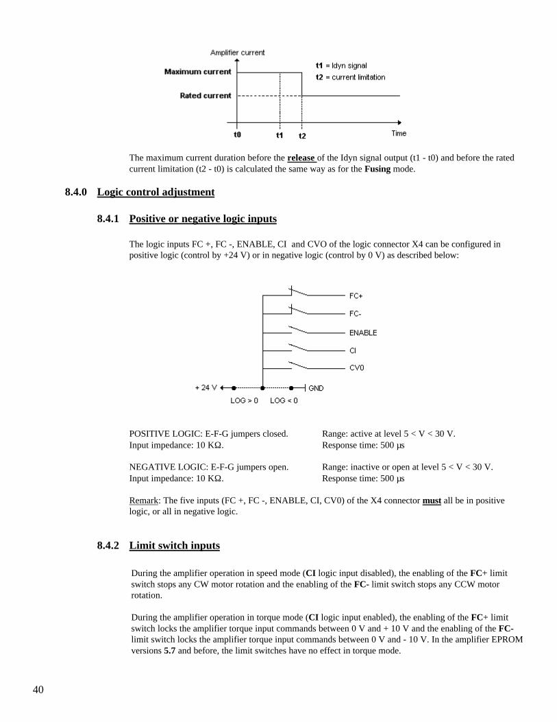
8.4.0 Logic control adjustment
8.4.1 Positive or negative logic inputs
The logic inputs FC +, FC -, ENABLE, CI and CVO of the logic connector X4 can be configured inpositive logic (control by +24 V) or in negative logic (control by 0 V) as described below:
POSITIVE LOGIC: E-F-G jumpers closed. Range: active at level 5 < V < 30 V.Input impedance: 10 KΩ. Response time: 500 µs
NEGATIVE LOGIC: E-F-G jumpers open. Range: inactive or open at level 5 < V < 30 V.Input impedance: 10 KΩ. Response time: 500 µs
Remark: The five inputs (FC +, FC -, ENABLE, CI, CV0) of the X4 connector must all be in positivelogic, or all in negative logic.
8.4.2 Limit switch inputs
During the amplifier operation in speed mode (CI logic input disabled), the enabling of the FC+ limitswitch stops any CW motor rotation and the enabling of the FC- limit switch stops any CCW motorrotation.
During the amplifier operation in torque mode (CI logic input enabled), the enabling of the FC+ limitswitch locks the amplifier torque input commands between 0 V and + 10 V and the enabling of the FC-limit switch locks the amplifier torque input commands between 0 V and - 10 V. In the amplifier EPROMversions 5.7 and before, the limit switches have no effect in torque mode.

41
8.4.3 “Amp ready” and “Power ready” outputs
If the position references have to be kept when a stored fault is released on the amplifier or when thepower supply is shut down or interrupted, it is possible:
• to reset the defaults via pin 13 of X4 without interrupting the logic supply,• to have a logic supply which is independent of the power supply (auxiliary supply) in order to be able
to cut the power supply without cutting the logic supply.
If the amplifier has an auxiliary supply on the PR8 connector, which is independent of the power supply,the J K L jumper on the logic board allows the Undervolt default when switching on the auxiliary supplybefore switching on the main power supply.
JK jumper closed and KL jumper open. With the auxiliary supply applied before the main powersupply, the "Undervolt." default is displayed and can hide a default of lower priority. The "AMP READY"and "POWER READY" outputs are both inactive (contact is open) until the power supply in on.
JK jumper open and KL jumper closed. The "Undervolt." default is inhibited when turning on theauxiliary supply before switching on the main power supply. The "AMP READY" output is then activeand "POWER READY" remains inactive (contact open) until the main power supply is on. In this case,the amplifier control must have the following relay logic:
o
o
o
o
o
oLogic
relay
Logic
"ON"
Logic
"OFF"
Logic
relay
o
o
o
o"ON"
Power
relay
Power
relay
o
o
o
o
E-STOP
"AMP READY"
Power
o
o
o
o
o
o
Enable
relay
Amplifier
"ON"
o
o
o
o
Enable
relay
Power
relay
"POWER READY"
Amplifier
"OFF"
24VDC
0VDC
.
.
.
. .
.
o
oK1
o
o
relay
Logic
Amp ready Amp ready signals of all axisPower ready Power ready signals of all axisPower relay Relay for power ONLogic relay Relay for logic ONENABLE relay Servo control relayK1 Auxiliary contact of the main isolation switch
42
8.5.0 BPCW software installation
8.5.1 System requirements (minimum)
To run the INFRANOR Digital Drive software, you need:• A computer with a 80386DX or greater processor• 4 Mbytes of RAM• Hard disk with at least 5 Mbytes of free space• VGA or higher resolution monitor• Mouse or other pointing device• Microsoft Windows, Version 3.1 or higher
8.5.2 Installing BPCW on your computer
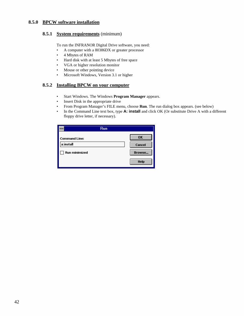
• Start Windows. The Windows Program Manager appears.• Insert Disk in the appropriate drive• From Program Manager’s FILE menu, choose Run. The run dialog box appears. (see below)• In the Command Line text box, type A: install and click OK (Or substitute Drive A with a different
floppy drive letter, if necessary).

43
• The BPCW screen appears (see below).• Modify the inputs Source, Destination and Group as necessary• Click on Install to start the software installation• After the copy of all files, click on Exit to close the installation procedure.
Source indicates the directory of the software original files.Destination indicates the directory where the files will be loaded.Group is the name of the software group under Program Manager.
Under Program Manager, click on BPCW Configuration in the Smtbd group for starting the softwareconfiguration.
• Configure the Communication port (port number and transmission speed)• Select the appropriate language.• Click on Save configuration.• Leave the configuration program by clicking on Exit• Click on Bpcw for starting the INFRANOR Digital Drive software.

44
8.6.0 360o shield on the connectors
There must never be a shield interruption on the whole cable length.
Self-sticking copper ribbon if necessary for increasing the shielddiameter to get properly tightened under the clamp
Connector on MAVILOR RBF RACKmotor for resolver and motor
The cable can be soldered on the shieldbecause the connector box is metalicThis solution does not correspond exactlyto the IEC requirements, but it is acceptable
Connector box on the MAVILOR motor
As short as possible
Ground
VU
WMetallic or metal plated plastic SMTBM-20ASub-D pin package
360 degrees shield ensured bythe tightening clamp
The fastening screw must be tightenedin order to ensure the shield continuityon the amplifier housing
Sub-D connector
Note: When the 360 degrees shield is made by means of a clamp, it is not necessary to connect a wire to the appropriate pin on the Sub-D connector


![User's Guide for LX Brushless Servo Drives[1]](https://static.fdocuments.net/doc/165x107/543b6f9eafaf9f4a578b483e/users-guide-for-lx-brushless-servo-drives1.jpg)


