Operating Manual RISH Master 3430 - rishabh.co.in · KVArh IN Ph R KAh VYB A KVA Min x1000 Hz KVAh...
79
RISH Master 3430 RISH Master 3430 Operating Manual %THD
-
Upload
vuongduong -
Category
Documents
-
view
217 -
download
1
Transcript of Operating Manual RISH Master 3430 - rishabh.co.in · KVArh IN Ph R KAh VYB A KVA Min x1000 Hz KVAh...
RISH Master 3430RISH Master 3430
Operating Manual
%THD

Section
Multi-function Digital MeterInstallation & Operating Instructions
Contents
1. Introduction
2. Measurement Reading Screens
3. Programming
3.1 Password Protection
INDEX
3.2 Set Up Screens
3.2.1 System Type
3.2.2 Potential Transformer Primary value
3.2.4 Current Transformer Primary value
3.2.5 Current Transformer Secondary value
3.2.6 Reset
3.2.8 Low current noise cutoff3.2.9 RS 485 Device Address3.2.10 RS 485 Baud rate3.2.11 RS 485 Parity Selection3.2.12 Assignment of Energy to Pulse output-13.2.13 Assignment of Energy to Pulse output-2
3.2.7 Auto Scrolling
3.2.3 Potential Transformer Secondary value
1

DMAN-00IM-0647 Rev D - 06/2018
3.2.15 Pulse rate3.2.16 Parameter setting for Analog output -13.2.17 Parameter setting for Analog output -23.2.18 Energy update rate3.2.19 Energy digit reset count.3.2.20 Energy display on Modbus
3.2.14 Pulse duration
10. Specification
8. Installation8.1 EMC Installation Requirements
8.2 Case Dimensions and Panel Cut-out8.3 Wiring 8.4 Auxiliary Supply
8.5 Fusing8.6 Earth / Ground Connections
9. Connection Diagrams
11. Connection for Optional Pulse output / RS 485 /Analog Ouput
4. Analog output option
Relay Output (optional)5.
Rs485 MODBUS Output
7. Phaser Diagram
6.
2
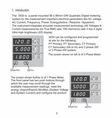
1. Introduction
The 3430 is a panel mounted 96 x 96mm DIN Quadratic Digital metering system for the measurement important electrical parameters like AC voltage, AC Current, Frequency, Power, Energy(Active / Reactive / Apparent) . The instrument integrates accurate measurement technology (All Voltages &Current measurements are True RMS upto 15th Harmonic) with 3 line 4 digitsUltra high brightness LED display.
3430 can be configured and programmedat site for the following : PT Primary, PT Secondary, CT Primary, CT Secondary (5A or1A) and 3 phase 3Wor 3 Phase 4W system.
Down Up
VRYKVAr
Sys
V x1000
KVArhIN
Ph RKAh
VYB A
KVAMin
x1000Hz
KVAh
Ph Y %THD
Angle
KWVBR
Max
x1000
P.F.
KWh
Ph B
Down Up
MaxKVAr
V x1000
KVArh
Angle
A
KVA
Minx1000
HzD
kVAh
KWkAh
x1000
P.F.kWh
%THD
The screen shown on left is of 3 Phase Meter.
The front panel has two push buttons throughwhich the user may scroll through theavailable measurement readings, reset the energy (Import/Export) Min/Max (System Voltageand System Current) and configure the product.
The screen shown further is of 1 Phase Meter.
3

TABLE 1:
Measured Parameters
System Voltage
System Current
Voltage VL1-N(4wire only)
Voltage VL2-N(4wire only)
Voltage VL3-N(4wire only)
Voltage VL1-L2
Voltage VL2-L3
Voltage VL3-L1
Current L1
Current L2
Current L3
Units of
Volts
Amps
Volts
Volts
Volts
Volts
Volts
Volts
Amps
Amps
Neutral Current ( 4 wire only )
Amps
Amps
Measurement
Active Import Energy (8 Digit resolution) kWh
kWhActive Export Energy (8 Digit resolution)
Active Power (System / Phase (4 wire only) )
Reactive Power (System / Phase (4 wire only))
Apparent Power (System / Phase (4 wire only))Power Factor (System / Phase (4 wire only))
Phase Angle ( Phase(4 wire only))
Kwatts
KVAr
KVA
Degree
kVArhReactive Import Energy (8 Digit resolution)
kVArhReactive Export Energy (8 Digit resolution)
kVAhApparent Energy (8 Digit resolution)
( for 3 / 4 wire)
( for 3 / 4 wire)
( for 3 / 4 wire)
( for 3 / 4 wire)
( for 3 / 4 wire)
( for 3 / 4 wire)
4
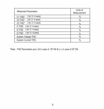
*Note : THD Parameters are L-N in case of 3P 4W & L-L in case of 3P 3W .
Measured ParametersUnits of
Measurement
I1 THD
I2 THD
V1 THD*V2 THD*
V3 THD*
%
I3 THD
System Voltage THD
System Current THD
%
%%
%
%%
%
( for 3 / 4 wire)
( for 3 / 4 wire)
( for 3 / 4 wire)
( for 3 / 4 wire)
( for 3 / 4 wire)
( for 3 / 4 wire)
5

2. Measurement Reading Screens
In normal operation the user is presented with one of the measurement reading screens out of several screens. These screens may be scrolled through one at a time in incremental order by pressing the “ Up key” and in decremental order by pressing “ Down key”.
Parameter Screens 1 Phase
System VoltageSystem Current
System Active Power
Phase AngleFrequency
System Power Factor
Reactive PowerApparent Power
Active Power
ActiveEnergy
Import
Min. System VoltageMin. System Current
ActiveEnergyExport
ReactiveEnergyImport
ReactiveEnergyExport
ApparentEnergy
Max. System VoltageMax. System Current
System Voltage Current % THD
6

Parameter Screens 3 Phase
System VoltageSystem Current
System Active Power
R Phase V L-N*Y Phase V L-N*B Phase V L-N*
R Phase CurrentY Phase Current
B Phase Current
Neutral Current*Frequency
System Power Factor
Reactive PowerApparent Power
Active Power
ActiveEnergy
Import
Min. System VoltageMin. System Current
ActiveEnergyExport
ReactiveEnergyImport
ReactiveEnergyExport
ApparentEnergy
Max. System VoltageMax. System Current
R Phase Reactive Power*R Phase Apparent Power*
R Phase Active Power*
Y Phase Reactive Power*Y Phase Apparent Power*
Y Phase Active Power*
B Phase Reactive Power*B Phase Apparent Power*
B Phase Active Power*
Phase Angle R*Phase Angle Y*Phase Angle B*
Phase Power Factor R*Phase Power Factor Y*Phase Power Factor B*
Voltage %THD
Current %THD
System Voltage Current % THD
VRY V L-LVYB V L-LVBR V L-L
A
A
NOTE: SCREENS MARKED WITH * ARE AVAILABLE ONLY IN 4W SYSTEM (NOT IN 3 WIRE SYSTEM)
7
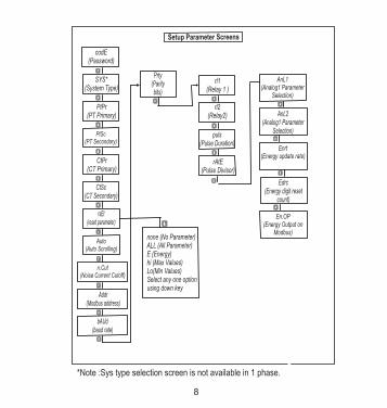
Setup Parameter Screens
SYS*(System Type)
PtPr(PT Primary)
PtSc(PT Secondary)
CtPr(CT Primary)
CtSc(CT Secondary)
rsEt(reset parameter)
Auto(Auto Scrolling)
n.Cut(Noise Current Cutoff)
Addr(Modbus address)
bAUd(baud rate)
Prty(Paritybits)
none (No Parameter)ALL (All Parameter)E (Energy)hi (Max Values)Lo(Min Values)Select any one optionusing down key
rl1(Relay 1 )
rl2(Relay2)
puls(Pulse Duration)
rAtE(Pulse Divisor)
codE(Password)
AnL1(Analog1 Parameter
Selection)
AnL2(Analog1 Parameter
Selection)
Enrt(Energy update rate)
Edrc(Energy digit reset
count)
En.OP(Energy Output on
Modbus)
*Note :Sys type selection screen is not available in 1 phase.
8

3.1. Password ProtectionPassword protection can be enabled to prevent unauthorized access to set-up screens, by default password protection is not enabled.
Password protection is enabled by selecting a four digit number other than 0000, setting a password of 0000 disables the password protection.
3. ProgrammingThe following sections comprise step by step procedures for configuring the3430 for individual user requirements.
To access the set-up screens press and hold the “Key simultaneously for 5 seconds. This will take the User into the PasswordProtection Entry Stage (Section 3.1).
Down” and “ Up”
VYB
VRYKVAr
Sys
V
A
KVAMin
KWVBR
AngleMax
x1000
KVArh
x1000
x1000
IN
Ph R
HzKVAh
Ph Y
P.F.
KWh
Ph B
KAh
%THD
9
VYB
VRYKVAr
Sys
V
A
KVAMin
KWVBR
AngleMax
x1000
KVArh
x1000
x1000
IN
Ph R
HzKVAh
Ph Y
P.F.
KWh
Ph B
KAh
%THD
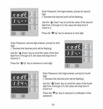
Enter Password, second digit entered, prompt for thirddigit.(* Denotes that decimal point will be flashing).
Use the “ Down” key to scroll the value of the thirddigit from 0 through to 9, the value will wrap from 9 round to 0.
Press the “ Up” key to advance to next digit.
VYB
VRYKVAr
Sys
V
A
KVAMin
KWVBR
AngleMax
x1000
KVArh
x1000
x1000
IN
Ph R
HzKVAh
Ph Y
P.F.
KWh
Ph B
KAh
%THD
Enter Password, third digit entered, prompt for fourthdigit.(* Denotes that decimal point will be flashing).
Use the “ Down” key to scroll the value of the fourthdigit from 0 through to 9, the value will wrap from 9 round to 0.
Press the “ Up” key to advance to verification of the password.
VYB
VRYKVAr
Sys
V
A
KVAMin
KWVBR
AngleMax
x1000
KVArh
x1000
x1000
IN
Ph R
HzKVAh
Ph Y
P.F.
KWh
Ph B
KAh
%THD
10
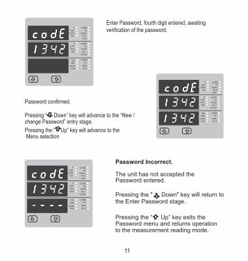
Enter Password, fourth digit entered, awaiting verification of the password.
VYB
VRYKVAr
Sys
V
A
KVAMin
KWVBR
AngleMax
x1000
KVArh
x1000
x1000
IN
Ph R
HzKVAh
Ph Y
P.F.
KWh
Ph B
KAh
%THD
Pressing the “ Up” key will advance to the
Password confirmed.
Pressing “ Down” key will advance to the “New / change Password” entry stage.
VYB
VRYKVAr
Sys
V
A
KVAMin
KWVBR
AngleMax
x1000
KVArh
x1000
x1000
IN
Ph R
HzKVAh
Ph Y
P.F.
KWh
Ph B
KAh
%THD
Password Incorrect.
The unit has not accepted the Password entered.
Pressing the " Down" key will return tothe Enter Password stage.
Pressing the “ Up” key exits the Password menu and returns operation to the measurement reading mode.
VYB
VRYKVAr
Sys
V
A
KVAMin
KWVBR
AngleMax
x1000
KVArh
x1000
x1000
IN
Ph R
HzKVAh
Ph Y
P.F.
KWh
Ph B
KAh
%THD
Menu selection
11

New / Change Password, first digit entered, prompting for second digit. (*Decimal point indicates that this will be flashing).
Pressing the “ Down” key will scroll the value of the second digit from 0 through to 9, the value will wrap from 9 round to 0.
Pressing the “ Up” key to advance the operation to the next digit and sets the second digit, in this case to “1”
VYB
VRYKVAr
Sys
V
A
KVAMin
KWVBR
AngleMax
x1000
KVArh
x1000
x1000
IN
Ph R
HzKVAh
Ph Y
P.F.
KWh
Ph B
KAh
%THD
New / Change Password
(*Decimal point indicates that this will be flashing).
Pressing the “ Down” key will scroll the value of the first digit from 0 through to 9, the value will wrap from 9 round to 0.
Pressing the “ Up” key to advance the operation to the next digit and sets the first digit, in this case to “2”
VYB
VRYKVAr
Sys
V
A
KVAMin
KWVBR
AngleMax
x1000
KVArh
x1000
x1000
IN
Ph R
HzKVAh
Ph Y
P.F.
KWh
Ph B
KAh
%THD
New / Change Password, second digit entered, prompting for third digit. (*decimal point indicates that this will be flashing).
Pressing the “ Down” key will scroll the value of the third digit from 0 through to 9, the value will wrap from 9 round to 0.
Pressing the “ Up” key to advance the operation to the next digit and sets the third digit, in this case to “5”
VYB
VRYKVAr
Sys
V
A
KVAMin
KWVBR
AngleMax
x1000
KVArh
x1000
x1000
IN
Ph R
HzKVAh
Ph Y
P.F.
KWh
Ph B
KAh
%THD
12

type confirmation menu.
New / Change Password, third digit entered, prompting for fourth digit. (* denotes that decimal point will be flashing).Pressing the “ Down” key will scroll the value of the fourth digit from 0 through to 9, the value will wrap from 9 round to 0.
Pressing the “ Up” key to advance the operation to the “New Password Confirmed” and sets the fourth digit, in this case to “3”.
VYB
VRYKVAr
Sys
V
A
KVAMin
KWVBR
AngleMax
x1000
KVArh
x1000
x1000
IN
Ph R
HzKVAh
Ph Y
P.F.
KWh
Ph B
KAh
%THD
VYB
VRYKVAr
Sys
V
A
KVAMin
KWVBR
AngleMax
x1000
KVArh
x1000
x1000
IN
Ph R
HzKVAh
Ph Y
P.F.
KWh
Ph B
KAh
%THD
New Password confirmed.
Pressing the “ Down” key will return to the “New/Change Password”.
Pressing the “ Up” key will advances to the Menu selection screen.(see section 3.2).
3.2 Set up Screens
3.2.1 System Type
VRY
KVArSys
V
KW
VBR
Angle
Max
x1000
KVArh
x1000
IN
Ph R
P.F.
KWh
Ph B
A
VYB
KVA
Min
x1000
Hz
KVAh
Ph Y
%THD
x1000
Hz
KVAh
Ph Y
%THD
This screen is used to set the system type .System type ”3” for 3 phase 3 wire & “4” for 3 phase 4 wire system.
Pressing the “ Up” key accepts the present
primary value Edit” menu (see section 3.2.2)
value and advances to the “Potential transformer
Pressing the “ Down” key will enter the system type edit mode and scroll the values through values available .
Pressing the “ Up” key advances to the system
13

This screen will only appear following the edit of system type. If system type is to be Downed again,
Pressing the “ Down” key will return to the system type edit stage by blanking the bottom line of the display
Pressing the “ Up” key sets the displayed value and will advance to “Potential Transformer Primary Value Edit” menu. (See section 3.2.2)
System Type Confirmation
Pressing the “ Up” key accepts the present value and advances to the “potential Transformer secondary Value edit” menu. (See Section 3.2.3)
Pressing the “ Down” key will enter the “Potential Transformer Primary Value Edit” mode.
Initially the “multiplier must be selected, pressing the “ Down” key will move the decimal point position to the right until it reaches # # # .# after which it will return to #. # # #.
Pressing the “ Up” key accepts the present multiplier (decimal point position) and advances to the “potential Transformer primary Digit Edit” mode.
3.2.2 Potential Transformer Primary Value
The nominal full scale voltage which will be displayed as the Line to Line voltages for all system types. The values displayed represent the voltage in kilovolts (note the x1000 enunciator).
VRY
KVArSys
V
KW
VBR
Angle
Max
x1000
KVArh
x1000
IN
Ph R
P.F.
KWh
Ph B
A
VYB
KVA
Min
x1000
Hz
KVAh
Ph Y
%THD
x1000
Hz
KVAh
Ph Y
%THD
VRY
KVArSys
V
KW
VBR
Angle
Max
x1000
KVArh
x1000
IN
Ph R
P.F.
KWh
Ph B
A
VYB
KVA
Min
x1000
Hz
KVAh
Ph Y
%THD
x1000
Hz
KVAh
Ph Y
%THD
14

Potential Transformer primary Digit Edit
Pressing the “ Down” key will scroll the value of the most significant digit from 0 through to 9 unless the presently displayed Potential Transformer Primary Value together with the Current Transformer Primary Value, previously set, would result in a maximum power
of greater than 666.6 MVA per phase in which case the digit range will be restricted.
Pressing the “ Up” key accepts the present value at the cursor position and advances the cursor to the next less significant digit.
The PT Primary value can be set from 100V L-L to 692.8 kV L-L.
Note : the flashing decimal point indicates the cursor position, a steady decimal point will be present to identify the scaling of the number until the cursor position coincides with the steady decimal point position. At this stage the decimal point will flash.
When the least significant digit has been set pressing the “ Up” key will advance to the “Potential Transformer Primary Value Confirmation” stage.
Screen showing display of 0.120 kV i.e. 120 Volts indicating steady decimal point and cursor flashing at the “hundreds of volts” position.
VRY
KVArSys
V
KW
VBR
Angle
Max
x1000
KVArh
x1000
IN
Ph R
P.F.
KWh
Ph B
A
VYB
KVA
Min
x1000
Hz
KVAh
Ph Y
%THD
x1000
Hz
KVAh
Ph Y
%THD
15
VRY
KVArSys
V
KW
VBR
Angle
Max
x1000
KVArh
x1000
IN
Ph R
P.F.
KWh
Ph B
A
VYB
KVA
Min
x1000
Hz
KVAh
Ph Y
%THD
x1000
Hz
KVAh
Ph Y
%THD
L-LNote : 0.120 kV i.e. 120 V
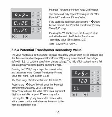
Potential Transformer Primary Value Confirmation
This screen will only appear following an edit of the Potential Transformer Primary Value.
If the scaling is not correct, pressing the “ Down” key will return to the “Potential Transformer Primary Value Edit” stage.
Pressing the “ Up” key sets the displayed value and will advance to the Potential Transformer secondary Value (See Section 3.2.3)
3.2.3 Potential Transformer secondary Value
The value must be set to the nominal full scale secondary voltage which will be obtained from the Transformer when the potential transformer(PT)primary is supplied with the voltage defined in 3.2.1.2. potential transformer primary voltage. The ratio of full scale primary to full scale secondary is defined as the transformer ratio.
The Valid range of instrument is from 100 to 600V
Transformer Secondary Value Edit” mode.“Down” key will scroll the value of the most significant digit from available range of PT secondary value
Pressing the “ Down” key will enter the “Potential
Pressing the “ Up” key accepts the present value and advances to the “Current Transformer Primary Value edit” menu. (See Section 3.2.4)
Pressing the “ Up” key accepts the present value at the cursor position and advances the cursor to the next less significant digit.
L-L .
VRY
KVArSys
V
KW
VBR
Angle
Max
x1000
KVArh
x1000
IN
Ph R
P.F.
KWh
Ph B
A
VYB
KVA
Min
x1000
Hz
KVAh
Ph Y
%THD
x1000
Hz
KVAh
Ph Y
%THD
16

Note : the flashing decimal point indicates the cursor position, a steady decimal point will be present to identify the scaling of the number until the cursor position coincides with the steady decimal point position. At this stage the decimal point will flash.
When the least significant digit has been set pressing the “ Up” key will advance to the “Potential Transformer secondary Value Confirmation” stage.
3.2.4 Current Transformer Primary Value
The nominal Full Scale Current that will be displayed as the Line currents. This screen enables the user to display the Line currents inclusive of any transformer ratios, the values displayed represent the Current in Amps.
Pressing the “ Up” key accepts the present value and advances to the Current Transformer Secondary Value (See Section 3.2.5)
Potential Transformer Secondary Value Confirmation
This screen will only appear following an edit of the Potential Transformer Secondary Value.
If the scaling is not correct, pressing the “ Down” key will return to the “Potential Transformer SecondaryValue Edit”
Pressing the “ Up” key sets the displayed value and will advance to the current Transformer PrimaryValue (See Section 3.2.4)
Pressing the “ Down” key will enter the “Current Transformer Primary Value Edit” mode.
This will scroll the value of the most significant digit from 0 through to 9,unless the presently
displayed Current Transformer Primary Value together with the Potential Transformer
VYB
VRYKVAr
Sys
V
A
KVAMin
KWVBR
AngleMax
x1000
KVArh
x1000
x1000
IN
Ph R
HzKVAh
Ph Y
P.F.
KWh
Ph B
KAh
%THD
17

range will be restricted, the value will wrap. Example: If primary value of PT is set as 692.8kV L-L (max value) then primary value
Pressing the “ Up” key will advance to the next less significant digit. (* Denotes that decimal point will be flashing).
Primary Value results in a maximum power of greater than 666.6 MVA in which case the digit
when the “ Up” key is pressed.
The “Maximum Power” restriction of 666.6 MVA refers to 120% of nominal current and 120% of nominal voltage, i.e, 462.96 MVA nominal power per phase.
When the least significant digit had been set, pressing the “ Up” key will advance to the “Current Transformer Primary Value Confirmation” stage.
The minimum value allowed is 1, the value will be forced to 1 if the display contains zero
of Current is restricted to 1157A.
Current Transformer Primary Value Confirmation.
This screen will only appear following an edit of the .
If the scaling is not correct, Pressing the “ Down” key will return to the “ Current Transformer Primary
Value”Edit stage with the most significant digit highlighted (associated decimal point flashing) and the bottom line of the display will be blanked.
Pressing the “ Up” key sets the displayed value and will advance to the “Current Transformer Secondary Value Edit” menu. (See Section 3.2.5)
Current Transformer Primary Value.
VRY
KVArSys
V
KW
VBR
Angle
Max
x1000
KVArh
x1000
IN
Ph R
P.F.
KWh
Ph B
A
VYB
KVA
Min
x1000
Hz
KVAh
Ph Y
%THD
x1000
Hz
KVAh
Ph Y
%THD
VRY
KVArSys
V
KW
VBR
Angle
Max
x1000
KVArh
x1000
IN
Ph R
P.F.
KWh
Ph B
A
VYB
KVA
Min
x1000
Hz
KVAh
Ph Y
%THD
x1000
Hz
KVAh
Ph Y
%THD
18

3.2.5 Current Transformer Secondary Value
This screen is used to set the secondary value for Current Transformer. Secondary value “5” for 5A or “1” for 1A can be selected. Pressing “ Up” key accepts the present value and advances to the Reset parameter screen (See Section 3.2.6)
Pressing the “ Down” key will enter the CT Secondary value edit mode and scroll the value through the values available.
Pressing the “ Up” key will advance to the CT Secondary value confirmation.
CT Secondary value confirmation
This screen will only appears following an edit of CT secondary value .
If secondary value shown is not correct, pressing the Down key will return to CT secondary edit stage by blanking the bottom line of the display.
Pressing “ Up” key sets the displayed value and will advance to reset parameter menu.(See Section 3.2.6)
VRY
KVArSys
V
KW
VBR
Angle
Max
x1000
KVArh
x1000
IN
Ph R
P.F.
KWh
Ph B
A
VYB
KVA
Min
x1000
Hz
KVAh
Ph Y
%THD
x1000
Hz
KVAh
Ph Y
%THD
VRY
KVArSys
V
KW
VBR
Angle
Max
x1000
KVArh
x1000
IN
Ph R
P.F.
KWh
Ph B
A
VYB
KVA
Min
x1000
Hz
KVAh
Ph Y
%THD
x1000
Hz
KVAh
Ph Y
%THD
19
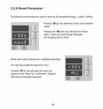
Pressing the “ Down” key will enter the “Resetoption” mode and scroll through Parameterand wrapping back to None.
Pressing “ Up” key advances to Auto scroll selection screen
The following screens allow the users to reset the All parameters,Energy , Lo(Min), hi(Max).
3.2.6 Reset Parameter :
Reset option select, (Resets ALL resettable parameter)
The user has scrolled through to the “ALL” .
Pressing “ Up” key will select the value and advance to the “Reset ALL Confirmation” Mode &.
Will reset all resettable parameter.
VYB
VRY
Sys
V
A
KVAMin
KWVBR
AngleMax
x1000
KVArh
x1000
x1000
IN
Ph R
HzKVAh
Ph Y
P.F.
KWh
Ph B
KAh
%THD
KVAr
Demand
VRY
KVArSys
V
KW
VBR
Angle
Max
x1000
KVArh
x1000
IN
Ph R
P.F.
KWh
Ph B
A
VYB
KVA
Min
x1000
Hz
KVAh
Ph Y
%THD
x1000
Hz
KVAh
Ph Y
%THD
20

VRY
KVArSys
V
KW
VBR
Angle
Max
x1000
KVArh
x1000
IN
Ph R
P.F.
KWh
Ph B
A
VYB
KVA
Min
x1000
Hz
KVAh
Ph Y
%THD
x1000
Hz
KVAh
Ph Y
%THD
VRY
KVArSys
V
KW
VBR
Angle
Max
x1000
KVArh
x1000
IN
Ph R
P.F.
KWh
Ph B
A
VYB
KVA
Min
x1000
Hz
KVAh
Ph Y
%THD
x1000
Hz
KVAh
Ph Y
%THD
VRY
KVArSys
V
KW
VBR
Angle
Max
x1000
KVArh
x1000
IN
Ph R
P.F.
KWh
Ph B
A
VYB
KVA
Min
x1000
Hz
KVAh
Ph Y
%THD
x1000
Hz
KVAh
Ph Y
%THD
Reset option select, (Reset Energy)
The user has scrolled through to the “E” Energyvalue.
Pressing “ Up” key will select the value and advance to the “Reset Energy Confirmation” Mode.
Reset Energy Confirmation.
Pressing “ Up” key resets the all Energy parametersand advances to the Auto scroll setting.(see section 3.2.7.)
Pressing the “ Down” key will re-enter the “Resetoption” mode.
Reset ALL Confirmation.
Pressing the “ Down” key will re-enter the “Reset option Select mode.
Pressing “ Up” key resets ALL the readings and advances to the Auto scroll.
21
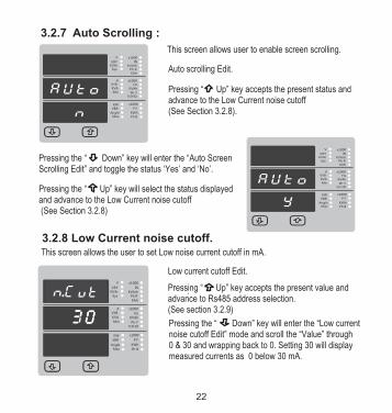
3.2.7 Auto Scrolling :
Pressing “ Up” key accepts the present status and advance to the Low Current noise cutoff (See Section 3.2.8).
This screen allows user to enable screen scrolling.
Auto scrolling Edit.
VYB
VRYKVAr
Sys
V
A
KVAMin
KWVBR
AngleMax
x1000
KVArh
x1000
x1000
IN
Ph R
HzKVAh
Ph Y
P.F.
KWh
Ph B
KAh
%THD
Pressing the “ Up” key will select the status displayed and advance to the Low Current noise cutoff (See Section 3.2.8)
Pressing the “ Down” key will enter the “Auto ScreenScrolling Edit” and toggle the status ‘Yes’ and ‘No’.
VYB
VRYKVAr
Sys
V
A
KVAMin
KWVBR
Angle
x1000
KVArh
x1000
x1000
IN
Ph R
HzKVAh
Ph Y
P.F.
KWh
KAh
%THD
Max Ph B
3.2.8 Low Current noise cutoff.This screen allows the user to set Low noise current cutoff in mA.
.Pressing “ Up” key accepts the present value and advance to Rs485 address selection.
Pressing the “ Down” key will enter the “Low currentnoise cutoff Edit” mode and scroll the “Value” through 0 & 30 and wrapping back to 0. Setting 30 will displaymeasured currents as 0 below 30 mA.
Low current cutoff Edit.
(See section 3.2.9)VYB
VRYKVAr
Sys
V
A
KVAMin
KWVBR
AngleMax
x1000
KVArh
x1000
x1000
IN
Ph R
HzKVAh
Ph Y
P.F.
KWh
Ph B
KAh
%THD
22
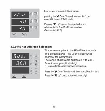
Low current noise cutoff Confirmation.
Pressing “ Up” key set displayed value and Advance to the Rs485 address selection.(See section 3.2.9)
pressing the “ Down” key will re-enter the “Low current Noise cutoff Edit” mode.
3.2.9 RS 485 Address Selection:
VRY
KVArSys
V
KW
VBR
Angle
Max
x1000
KVArh
x1000
IN
Ph R
P.F.
KWh
Ph B
A
VYB
KVA
Min
x1000
Hz
KVAh
Ph Y
%THD
x1000
Hz
KVAh
Ph Y
%THD
This screen applies to the RS 485 output only.
This screen allows the user to set RS485 address for instruments
Enter Address, prompt for first digit.(* Denotes that decimal point will be flashing).
Press the “ Down” key to scroll the value of the first digit
Press the “ Up” key to advance to next digit.
The range of allowable address is 1 to 247 .
VYB
VRYKVAr
Sys
V
A
KVAMin
KWVBR
AngleMax
x1000
KVArh
x1000
x1000
IN
Ph R
HzKVAh
Ph Y
P.F.
KWh
Ph B
KAh
%THD
23

VYB
VRYKVAr
Sys
V
A
KVAMin
KWVBR
AngleMax
x1000
KVArh
x1000
x1000
IN
Ph R
HzKVAh
Ph Y
P.F.
KWh
Ph B
KAh
%THD
Enter Address, first digit entered, prompt for second
digit (* Denotes that decimal point will be flashing).
Use the “ Down” key to scroll the value of the
Press the “ Up” key to advance to next digit.
VYB
VRYKVAr
Sys
V
A
KVAMin
KWVBR
AngleMax
x1000
KVArh
x1000
x1000
IN
Ph R
HzKVAh
Ph Y
P.F.
KWh
Ph B
KAh
%THD
Enter Address, second digit entered, prompt for third
digit (* Denotes that decimal point will be flashing).
Use the “ Down” key to scroll the value of the third digit
VYB
VRYKVAr
Sys
V
A
KVAMin
KWVBR
AngleMax
x1000
KVArh
x1000
x1000
IN
Ph R
HzKVAh
Ph Y
P.F.
KWh
Ph B
KAh
%THD
Address confirmation Screen.
This Screen confirms the Address set by user .
Press the “ Up” key to advance to next Screen
“Rs485 Baud Rate” (See Section 3.2.10)
Pressing the “ Down” key will reenter the “AddressEdit” mode.
second digit
24

RS 485 Baud Rate confirmation :
Pressing “ Down” key will be re-enter into Baud Rate Edit mode .
3.2.10 RS 485 Baud Rate :
This screen allows the user to set Baud Rate of RS 485 port.
The values displayed on screen are in kbaud .
Pressing “ Up” key accepts the present value and advance to the Parity Selection (see section 3.2.11).
Pressing the “ Down” key will enter the “Baud RateEdit” mode and scroll the value through 2.4, 4.8, 9.6 , 19.2 and back to 2.4
Pressing the “ Up” key will select the value and advances to the Parity Selection (see section 3.2.11).
VRY
KVArSys
V
KW
VBR
Angle
Max
x1000
KVArh
x1000
IN
Ph R
P.F.
KWh
Ph B
A
VYB
KVA
Min
x1000
Hz
KVAh
Ph Y
%THD
x1000
Hz
KVAh
Ph Y
%THD
VRY
KVArSys
V
KW
VBR
Angle
Max
x1000
KVArh
x1000
IN
Ph R
P.F.
KWh
Ph B
A
VYB
KVA
Min
x1000
Hz
KVAh
Ph Y
%THD
x1000
Hz
KVAh
Ph Y
%THD
25

3.2.11 RS 485 Parity Selection :
This screen allows the user to set Parity & number of stop bits of RS 485 port.
Pressing “ Up” key accepts the present value and advance to the Pulse output 1 selection (see section 3.2.12).Pressing the “ Down” key will enter the “Parity & stop bit Edit” mode and scroll the value through
odd : odd parity with one stop bit
no 1 : no parity with one stop bit
no 2 : no parity with two stop bit
E : even parity with one stop bit
Pressing the “ Up” key will set the value and advances to the Pulse output Selection (see section 3.2.12).
RS 485 Parity confirmation :
Pressing “ Down” key will be re-enter into Parity Edit mode .
VRY
KVArSys
V
KW
VBR
Angle
Max
x1000
KVArh
x1000
IN
Ph R
P.F.
KWh
Ph B
A
VYB
KVA
Min
x1000
Hz
KVAh
Ph Y
%THD
x1000
Hz
KVAh
Ph Y
%THD
VRY
KVArSys
V
KW
VBR
Angle
Max
x1000
KVArh
x1000
IN
Ph R
P.F.
KWh
Ph B
A
VYB
KVA
Min
x1000
Hz
KVAh
Ph Y
%THD
x1000
Hz
KVAh
Ph Y
%THD
26
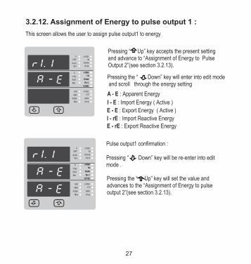
3.2.12. Assignment of Energy to pulse output 1 :
Pressing “ Up” key accepts the present settingand advance to “Assignment of Energy to Pulse Output 2”(see section 3.2.13).
This screen allows the user to assign pulse output1 to energy
Pressing the “ Down” key will enter into edit mode and scroll through the energy setting
A - E : Apparent Energy
I - E : Import Energy ( Active )
E - E : Export Energy ( Active )
I - rE : Import Reactive Energy
E - rE : Export Reactive Energy
Pressing the “ Up” key will set the value and advances to the “Assignment of Energy to pulse output 2”(see section 3.2.13).
Pulse output1 confirmation :
Pressing “ Down” key will be re-enter into edit mode .
VRY
KVArSys
V
KW
VBR
Angle
Max
x1000
KVArh
x1000
IN
Ph R
P.F.
KWh
Ph B
A
VYB
KVA
Min
x1000
Hz
KVAh
Ph Y
%THD
x1000
Hz
KVAh
Ph Y
%THD
VRY
KVArSys
V
KW
VBR
Angle
Max
x1000
KVArh
x1000
IN
Ph R
P.F.
KWh
Ph B
A
VYB
KVA
Min
x1000
Hz
KVAh
Ph Y
%THD
x1000
Hz
KVAh
Ph Y
%THD
27

3.2.13. Assignment of Energy to pulse output 2 :
This screen allows the user to assign pulse output 2 to energy
Pressing “ Up” key accepts the present settingand advance to “Pulse Duration”(see section 3.2.14).
Pressing the “ Down” key will enter into edit mode and scroll through the energy setting
A - E : Apparent Energy
I - E : Import Energy ( Active )
E - E : Export Energy ( Active )
I - rE : Import Reactive Energy
E - rE : Export Reactive Energy
Pressing the “ Up” key will set the value and advances to the “Pulse duration”(see section 3.2.14).
Pulse output 2 confirmation :
Pressing “ Down” key will be re-enter into edit mode .
VRY
KVArSys
V
KW
VBR
Angle
Max
x1000
KVArh
x1000
IN
Ph R
P.F.
KWh
Ph B
A
VYB
KVA
Min
x1000
Hz
KVAh
Ph Y
%THD
x1000
Hz
KVAh
Ph Y
%THD
VRY
KVArSys
V
KW
VBR
Angle
Max
x1000
KVArh
x1000
IN
Ph R
P.F.
KWh
Ph B
A
VYB
KVA
Min
x1000
Hz
KVAh
Ph Y
%THD
x1000
Hz
KVAh
Ph Y
%THD
28
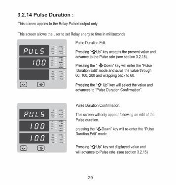
Pressing “ Up” key set displayed value and will advance to Pulse rate (see section 3.2.15)
Pulse Duration Confirmation.
This screen will only appear following an edit of the Pulse duration.
pressing the “ Down” key will re-enter the “PulseDuration Edit” mode.
3.2.14 Pulse Duration :
This screen applies to the Relay Pulsed output only.
This screen allows the user to set Relay energise time in milliseconds.
Pressing “ Up” key accepts the present value and advance to the Pulse rate (see section 3.2.15).
Pressing the “ Up” key will select the value and advances to “Pulse Duration Confirmation”.
Pressing the “ Down” key will enter the “Pulse Duration Edit” mode and scroll the value through 60, 100, 200 and wrapping back to 60.
Pulse Duration Edit.VRY
KVArSys
V
KW
VBR
Angle
Max
x1000
KVArh
x1000
IN
Ph R
P.F.
KWh
Ph B
A
VYB
KVA
Min
x1000
Hz
KVAh
Ph Y
%THD
x1000
Hz
KVAh
Ph Y
%THD
VRY
KVArSys
V
KW
VBR
Angle
Max
x1000
KVArh
x1000
IN
Ph R
P.F.
KWh
Ph B
A
VYB
KVA
Min
x1000
Hz
KVAh
Ph Y
%THD
x1000
Hz
KVAh
Ph Y
%THD
29
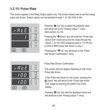
Pressing the “ Down” key will enter the “Pulse rate divisor Edit” mode and scroll the value through the values 1,10,100,1000 wrapping back to 1 in Wh but in KWh & MWh pulse rate divisor is only 1 .
3.2.15. Pulse Rate
This screen applies to the Relay Output option only. The screen allows user to set the energypulse rate divisor. Divisor values can be selected through 1,10,100,1000 in Wh .
Pressing “ Up” key accepts the presents value and advances to the “Analog output 1” menu (See section 3.2.16).
Pressing the “ Up” key advances to the “Pulse rate Divisor Confirmation” menu.
Pulse Rate Divisor Confirmation.
This screen will only appear following an edit of the Pulse rate divisor.
If the Pulse rate shown is not correct, pressing the “ Down” key will return to the “Pulse rate divisor
Edit” stage by blanking the bottom line of the display.
Pressing “ Up” key sets the displayed value and will advance to the “Analog output 1” menu.
VRY
KVArSys
V
KW
VBR
Angle
Max
x1000
KVArh
x1000
IN
Ph R
P.F.
KWh
Ph B
A
VYB
KVA
Min
x1000
Hz
KVAh
Ph Y
%THD
x1000
Hz
KVAh
Ph Y
%THD
VRY
KVArSys
V
KW
VBR
Angle
Max
x1000
KVArh
x1000
IN
Ph R
P.F.
KWh
Ph B
A
VYB
KVA
Min
x1000
Hz
KVAh
Ph Y
%THD
x1000
Hz
KVAh
Ph Y
%THD
30

31
VRY
KVArSys
V
KW
VBR
Angle
Max
x1000
KVArh
x1000
IN
Ph R
P.F.
KWh
Ph B
Pressing the “ Down” key will re-enter the “ Analog output 1 Edit”
Analog output 1 Confirmation :
Pressing the “ Up” key sets the displayed value and will advance to the Analog output 2 selection ( see section 3.2.17 )
VRY
KVArSys
V
KW
VBR
Angle
Max
x1000
KVArh
x1000
IN
Ph R
P.F.
KWh
Ph B
3.2.16 Analog Output 1 Selection : ( Optional )
This screen is for analog output 1 only . It allows the user to set analog output 1 to corresponding measured parameter . Refer table “ Parameter for Analog output “.
Pressing “ Up” key accepts the present value and advance to the Analog output 2 selection (see section 3.2.17).Pressing the “ Down” key will enter the“ Analog output 1 Edit” mode and scroll the values, as per Table “ Parameter for Analog output”
Pressing the “ Up” key advance to the Analog output 1 confirmation screen .
A
VYB
KVA
Min
x1000
Hz
KVAh
Ph Y
%THD
x1000
Hz
KVAh
Ph Y
%THD
A
VYB
KVA
Min
x1000
Hz
KVAh
Ph Y
%THD
x1000
Hz
KVAh
Ph Y
%THD

32
VRY
KVArSys
V
KW
VBR
Angle
Max
x1000
KVArh
x1000
IN
Ph R
P.F.
KWh
Ph B
VRY
KVArSys
V
KW
VBR
Angle
Max
x1000
KVArh
x1000
IN
Ph R
P.F.
KWh
Ph B
3.2.17 Analog Output 2 Selection : ( Optional )
This screen is for analog output 2 only . It allows the user to set analog output 2 to corresponding measured parameter . Refer table “ Parameter for Analog output “.
Pressing “ Up” key accepts the present value and advances to Energy update rate screen.
Pressing the “ Down” key will enter the “ Analog output 2 Edit” mode and scroll the values, as per Table “ Parameter for Analog output”
Pressing the “ Up” key advance to the Analog output 2 confirmation screen .
A
VYB
KVA
Min
x1000
Hz
KVAh
Ph Y
%THD
x1000
Hz
KVAh
Ph Y
%THD
VRY
KVArSys
V
KW
VBR
Angle
Max
x1000
KVArh
x1000
IN
Ph R
P.F.
KWh
Ph B
VRY
KVArSys
V
KW
VBR
Angle
Max
x1000
KVArh
x1000
IN
Ph R
P.F.
KWh
Ph B
Pressing the “ Down” key will re-enter the “ Analog output 2 Edit”
Analog output 2 Confirmation :
Pressing the “ Up” key sets the displayed value and will advances to Energy update rate screen.
A
VYB
KVA
Min
x1000
Hz
KVAh
Ph Y
%THD
x1000
Hz
KVAh
Ph Y
%THD

Pressing the “ Down” key will enter the Energy update rate edit mode. This will scroll the value of most significant digit.
Pressing the “ Up” key sets the displayed value and will advances to Energy digit reset count screen.
This screen is for energy update rate. it allows user to set energy update rate in minutes. It is settable from 1 to 60 min.
3.2.18 Energy Update Rate :
Pressing “ Up key “ will advance to Energy update rate confirmation screen. Pressing the “ Down” key will re-enter Energy update rate edit mode.
Pressing the “ Down” key will scroll the value of second digit.
Pressing the “ Up” key sets the displayed value and advances to Energy digit reset count” menu.
VRY
KVArSys
V
KW
VBR
Angle
Max
x1000
KVArh
x1000
IN
Ph R
P.F.
KWh
Ph B
VRY
KVArSys
V
KW
VBR
Angle
Max
x1000
KVArh
x1000
IN
Ph R
P.F.
KWh
Ph B
A
VYB
KVA
Min
x1000
Hz
KVAh
Ph Y
%THD
x1000
Hz
KVAh
Ph Y
%THD
Pressing the “ Up” key sets the displayed value and will advance to Energy display on Modbus menu.
3.2.19 Energy Digit reset count :
This screen enables user for setting maximum energy count “ after which energy will rollback to zero depends upon setting of Wh,KWh,& MWh.
VRY
KVArSys
V
KW
VBR
Angle
Max
x1000
KVArh
x1000
IN
Ph R
P.F.
KWh
Ph B
VRY
KVArSys
V
KW
VBR
Angle
Max
x1000
KVArh
x1000
IN
Ph R
P.F.
KWh
Ph B
A
VYB
KVA
Min
x1000
Hz
KVAh
Ph Y
%THD
x1000
Hz
KVAh
Ph Y
%THD
Pressing “ Up key “ will advance to next less significant digit. (* Denotes that decimal point is flashing).
Pressing the “ Down” key will enter the Energy digit reset count edit mode. This will scroll the value of reset count from7 to 14 for Wh, from 7 to 12 for KWh & from 7 to 9 for MWh.
33

Pressing the “ Up” key sets the displayed value and will advance to “Energy on Modbus menu.
Pressing “ Up key “ will advance to Energy digit reset count confirmation screen.Pressing the “ Down” key will re-enter Energy digit reset count edit mode.
Note : 1) Default value is set to “14” i.e if energy count crosses 14 digit it will rollback to zero. 2) Energy displays on modbus is set to (2) & energy digit reset count is set to 12. Energy screen on display will show “-------” i.e energy overflow .when energy crosses the 11 digit count. 3) Energy displays on modbus is set to (3) & energy digit reset count is set to 9.Energy screen on display will show “-------” i.e energy overflow .when energy crosses the 8 digit count.
Pressing “ Up” key accepts the presents value and returns to measurement screen.
3.2.20 Energy Display on modbus
Pressing the “ Down” key will enter the “Energy Display On Modbus Edit” mode and scroll the value through the values 1,2 & 3 wrapping back to 1.1 : Energy In Wh2 : Energy in KWh3: Energy in MWh.
VRY
KVArSys
V
KW
VBR
Angle
Max
x1000
KVArh
x1000
IN
Ph R
P.F.
KWh
Ph B
A
VYB
KVA
Min
x1000
Hz
KVAh
Ph Y
%THD
x1000
Hz
KVAh
Ph Y
%THD
This screen enable user to set energy in terms of Wh / KWh / MWh on RS 485 Output depending as per the requirement .Same applicable for all types of energy.
Ex. If energy display on modbus is set Wh & It will set Energy digit count to 10 then energy will reset after “9,999,999,999” & then will Rollback to zero.
34

Pressing “ Up” key sets the displayed value and will return to measurement screen.
Energy Display On Modbus Confirmation.
This screen will only appear following an edit of the Energy Display On Modbus.
VRY
KVArSys
V
KW
VBR
Angle
Max
x1000
KVArh
x1000
IN
Ph R
P.F.
KWh
Ph B
A
VYB
KVA
Min
x1000
Hz
KVAh
Ph Y
%THD
x1000
Hz
KVAh
Ph Y
%THDPressing the “ Down” key will enter the “Energy Display On Modbus Edit” stage by blanking the bottom line of the display.
Note : Default value is set to ‘1’ i.e. Energy on Modbus will be in terms of Wh/VArh/VAh resp.
Pressing the “ Up” key advances to the returns to Measurement screen.
35

36
4. Analog Output ( optional ) :
This module provides two d.c. isolated outputs .There are two output options
1) Two 0 - 1mA outputs , internally powered .2) Two 4 - 20mA outputs , internally powered .
The 0 -1mA output module has an 0V return on each end of the 4 way connector ( Please refer section 15 for connection details )
On both modules the output signals are present on pins A1(Analog Output 1) & A2 (Analog Output 2)
These outputs can be individually assigned to represent any one of the measured and displayed Parameters.
All settlings are user congurable via the user interface screen. See Analog o/p selection ( section 3.2.16 & section 3.2.17 ) for details .
* Note : Refer diagrams 1 & 2

37
Diagram 1 : ( 4 -20 mA )00 (12 mA)
0181 (4 mA)
0180 (20 mA)
090 (16 mA)
0270 (8 mA)
Diagram 2 : ( 0 - 1 mA )0
0 (0.5 mA)
0181 (0 mA)
0180 (1 mA)
090 (0.75 mA)
0270 (0.25 mA)
38
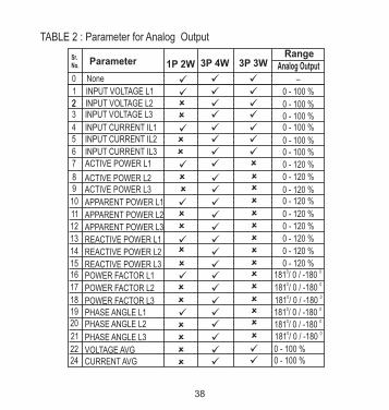
TABLE 2 : Parameter for Analog Output
0 - 120 %8 ACTIVE POWER L20 - 120 %
9 ACTIVE POWER L3
0 - 120 %
10 APPARENT POWER L1
0 - 120 %
11 APPARENT POWER L2 12 APPARENT POWER L313 REACTIVE POWER L114 REACTIVE POWER L215 REACTIVE POWER L316 POWER FACTOR L1 17 POWER FACTOR L2
18 POWER FACTOR L319 PHASE ANGLE L1 20 PHASE ANGLE L2
21 PHASE ANGLE L3
0 - 120 %
0 - 120 %
0 - 120 %
0 - 120 %0 0
181 / 0 / -1800 0181 / 0 / -1800 0
181 / 0 / -1800 0181 / 0 / -1800 0
181 / 0 / -1800 0181 / 0 / -180
22 VOLTAGE AVG 24 CURRENT AVG
0 - 100 %0 - 100 %
INPUT VOLTAGE L1
Sr.No. Parameter
0
1
2 INPUT VOLTAGE L223 INPUT VOLTAGE L3
None
4 INPUT CURRENT IL1
3P 4W1P 2W 3P 3WRange
0 - 100 %
0 - 100 %
0 - 100 %0 - 100 %
5 INPUT CURRENT IL2
6 INPUT CURRENT IL30 - 100 %0 - 100 %
0 - 120 %
7 ACTIVE POWER L1
–
Analog Output

39
0181 / 0 / -180
27 ACTIVE POWER SUM 29 APPARENT POWER SUM 31 REACTIVE POWER SUM
32 POWER FACTOR AVG 34 PHASE ANGLE AVG
0 - 120 %0 - 120 %
0 - 120 %
Sr.No. Parameter 3P 4W1P 2W 3P 3W
RangeAnalog Output
0181 / 0 / -180
101 INPUT VOLTAGE L12
102 INPUT VOLTAGE L23
103 INPUT VOLTAGE L31 113 NEUTRAL CURRENT
0 - 100 %
0 - 100 %
0 - 100 %0 - 100 %
Note : Parameters 1,2,3 are L-N Voltage for 3P 4W & L-L Voltage for 3P 3W .(1) For Frequency 0% corresponds to 40 Hz & 120% corresponds to 70 Hz.(2) For Angle and PF 0% corresponds to 0 Deg. & 100% corresponds to 360 Deg.
36 Frequency 45 to 65 Hz

System power = Root3 x CT(Primary) x PT(Primary)L-L for 3 Phase 3 Wire
5. Relay output (Optional) : This is provided with either 1 or 2 relay for pulse output . instrument
Pulse Output : Pulse output is the potential free, very fast acting relay contact which can be used to drive an external mechanical counter for energy measurement.
Pulse Duration 60 ms,100 ms or 200 ms
Divisor
1
10
100
1000
Pulse ratePulse System Power*
1per Wh
1per 10Wh
1per 100Wh
1 per 1000Wh
1per kWh
1per 10kWh
1per 100kWh
1 per 1000kWh
1per Mwh
1per 10MWh
1per 100MWh
1per 1000MWh
Up to 3600W
Up to 3600W
Up to 3600W
Up to 3600W
Up to 3600kW
Up to 3600kW
Up to 3600kW
Up to 3600kW
Above 3600kW
Above 3600kW
Above 3600kW
Above 3600kW
TABLE 3 : Energy Pulse Rate Divisor
1.For Energy Output in Wh
Divisor
1
Pulse ratePulse System Power*
1 per kWh1 per 1000kWh
1 per 1000MWh
Up to 3600WUp to 3600kWAbove 3600kW
2. For Energy Output in Kwh
Divisor
1
Pulse ratePulse System Power*
1 per Mwh1 per 1000Mwh1 per 1000Gwh
Up to 3600WUp to 3600kWAbove 3600kW
3. For Energy Output in Mwh
This pulse output can be congured to any of the following parameter instrument’sthrough setup parameter screen
1) Active Energy (Import)2) Active Energy (Export) 3) Reactive Energy (Import)
4) Reactive Energy (Export) 5) Apparent Energy
* System power = 3 x CT(Primary) x PT(Primary)L-N for 3 Phase 4 Wire
Above options are also applicable for Apparent and Reactive Energy.
40
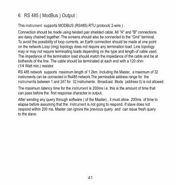
6. RS 485 ( ModBus ) Output :
This supports MODBUS (RS485) RTU protocol( 2-wire ) .instrument
Connection should be made using twisted pair shielded cable. All "A" and "B" connections are daisy chained together. The screens should also be connected to the “Gnd” terminal. To avoid the possibility of loop currents, an Earth connection should be made at one point on the network.Loop (ring) topology does not require any termination load. Line topology may or may not require terminating loads depending on the type and length of cable used. The impedance of the termination load should match the impedance of the cable and be at bothends of the line. The cable should be terminated at each end with a 120 ohm (1/4 Watt min.) resistor.
RS 485 network supports maximum length of 1.2km. Including the Master, a maximum of 32 instruments can be connected in Rs485 network.The permissible address range for the
is between 1 and 247 for 32 instruments. Broadcast Mode (address 0) is not allowed.instrument
The maximum latency time for the is 200ms i.e. this is the amount of time that instrumentcan pass before the rst response character is output.
After sending any query through software ( of the Master) , it must allow 200ms of time to elapse before assuming that the is not going to respond. If slave does not instrumentrespond within 200 ms, Master can ignore the previous query and can issue fresh query to the slave.
41

The each byte in RTU mode has following format:
8-bit binary, hexadecimal 0-9, A-F
2 hexadecimal characters contained in each 8-bit eld of the message
4 bytes (32 bits) per parameter.
Floating point format ( to IEEE 754)Most signicant byte rst (Alternative least signicant byte rst)
Format of Data Bytes
2 byte Cyclical Redundancy Check (CRC)Error Checking Bytes
1 start bit,8 data bits, least signicant bit sent rst1 bit for even/odd parity1 stop bit if parity is used; 1 or 2 bits if no parity
Byte format
Communication Baud Rate is user selectable from the front panel between 2400, 4800, 9600, 19200 bps.
Exception Cases : An exception code will be generated when the receives instrumentModBus query with valid parity & error check but which contains some other error ( e.g. Attempt to set oating point variable to an invalid value ) The response generated will be “Function code” Ored with HEX (80H ). The exception codes are listed below
Function code :
03 Read Holding Registers Read content of read /write location ( 4X )
04 Read input Registers Read content of read only location ( 3X )
16 Presets Multiple Registers Set the content of read / write locations ( 4X )
42

03 Illegal DataValue
Attempt to set a oating point variable to an invalid value
01 Illegal function This function code is not supported by the instrument.
02 Illegal DataAddress
Attempt to access an invalid address or an attempt to read or write part of a oating point value
Two consecutive 16 bit registers represent one parameter. Refer table 4 for the addresses of 3X registers (Parameters measured by the instruments).Each parameter is held in the 3X registers. Modbus Code 04 is used to access all parameters.
Example :
To read parameter , Volts 3 : Start address = 04 (Hex) Number of registers = 02
Note : Number of registers = Number of parameters x 2
Each Query for reading the data must be restricted to 20 parameters or less. Exceeding the 20 parameter limit will cause a ModBus exception code to be returned.
Query :
Accessing 3 X register for reading measured values:
DeviceAddress
Function Code
Start Address High
Start Address Low
Number ofRegisters Hi
Number ofRegisters Lo
CRCLow
CRCHigh
01 (Hex) 04 (Hex) 00 (Hex) 04(Hex) 00 (Hex) 02(Hex) 30 (Hex) 0A (Hex)
Start Address High : Most signicant 8 bits of starting address of the parameter requested.
Start Address low :Least signicant 8 bits of starting address of the parameter requested.
43

Number of register Hi : Most signicant 8 bits of Number of registers requested.
Number of register Lo : Least signicant 8 bits of Number of registers requested.
(Note : Two consecutive 16 bit register represent one parameter.)
Response: Volt3 (219.25V)
DeviceAddress
Function Code
ByteCount
Data Register1 High Byte
01 (Hex) 04 (Hex) 04 (Hex) 43 (Hex) 5B (Hex) 41 (Hex) 21 (Hex) 6F (Hex)
Data Register1 Low Byte
Data Register2 High Byte
Data Register2 Low Byte
CRCLow
CRCHigh
9B (Hex)
Byte Count : Total number of data bytes received.
Data register 1 High Byte : Most signicant 8 bits of Data register 1 of the parameter requested.Data register 1 Low Byte : Least signicant 8 bits of Data register 1 of the parameter requested.
Data register 2 High Byte : Most signicant 8 bits of Data register 2 of the parameter requested.
(Note : Two consecutive 16 bit register represent one parameter.)
Data register 2 Low Byte : Least signicant 8 bits of Data register 2 of the parameter requested.
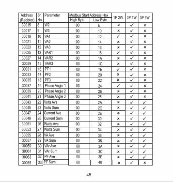
Table 4 : 3 X register addresses (measured parameters)
3P 4W 3P 3W
1P 2W
Parameter
Volts 1
Volts 2
Volts 3
Current 1
Current 2
Current 3
W1
Modbus Start Address HexHigh Byte Low Byte
00 0
00 2
00 4
00 600 8
00 A00 C
Address(Register)
Sr.No.
30001 1
30003 2
30005 3
30007 4
30009 5
30011 6
30013 7
44
30023 12
30025 13
30027 14
30029 15
30031 16
30033 17
30035 18
30037 19
30039 20
30041 21
30043 22
30045 23
30047 24
30049 25
30051 26
30053 27
30055 28
30057 29
30059 30
30061 31
30063 32
Address(Register)
Sr.No.
30015 8
30017 9
30019 10
.
30021 11
VA3
VAR1
VAR2
VAR3
PF1
PF2
PF3
Phase Angle 1
Phase Angle 2
Phase Angle 3
Volts Ave
Volts Sum
Current Ave
Current Sum
Watts Ave
Watts Sum
VA Ave
VA Sum
VAr Ave
VAr Sum
PF Ave
Parameter
W2
W3
VA1
VA2
00 1600 18
00 1A
00 1C
00 1E
00 20
00 22
00 24
00 2600 28
00 2A
00 2C00 2E00 30
00 32
00 34
00 3600 38
00 3A00 3C00 3E
Modbus Start Address HexHigh Byte Low Byte
00 E
00 10
00 1200 14
3P 4W1P 2W 3P 3W
30065 33 PF Sum 00 40
45

30071 36
30073 37
30075 38
30077 39
30079 40
30081 41
Address(Register)
Sr.No.
51
Freq
Wh Import
Wh Export
VARh Import
VARh Export
VAh
Parameter
00 46
00 4800 4A
00 4C00 4E
00 50
Modbus Start Address HexHigh Byte Low Byte
1P 2W
3P 4W 3P 3W
30067 34
30069 35
Phase Angle Ave
Phase Angle Sum
00 42
00 44
30109 00 6C Wh Import Overow Count
00 6E Wh Export Overow Count
00 70 Varh Import Overow Count
00 72 Varh Export Overow Count
00 74 Vah OverowCount
30111
30113
30115
30117
52
53
54
55
30143 60 Current Ave Min 00 8E
30147
30149
62
63
30145 00 90 61 Wh Import
57
58
59
3013330135
30141
Volts Ave MaxVolts Ave Min
8486
8CCurrent Ave Max
00
00
00
(On Update Rate)
00 92 Wh Export
(On Update Rate)
00 94 Varh Import
(On Update Rate)
46

1P 2W
3P 4W 3P 3W
Address(Register)
Sr.No.
30203
30205
30207
30209
30211
3021330215
30217
30219
69
70
71
72
73
7475
76
77
Parameter
VL 2 - 3 ( Calculated )
VL 3 - 1 ( Calculated )
V1 THD( % )
V2 THD( % )
V3 THD( % )
I1 THD( % )I2 THD( % )
I3 THD( % )
System Voltage THD( % )
Modbus Start Address HexHigh Byte Low Byte
00
00
00
00
00
0000
00
00
CA
CC
CE
D0
D2
D4D6
D8
DA
30201 VL 1 - 2 ( Calculated ) 00 C8
30151
30153
30197
30199
64
65
66
67
00
00
C4
C6
Model Number
Version Number
68
00 96 Varh Export
(On Update Rate)
00 9A Vah
(On Update Rate)
Note : Parameters 1,2,3 are L-N Voltage for 3P 4W & L-L Voltage for 3P 3W .
30225 79 I neutral 00 E0
47

Query :
Start Address High : Most signicant 8 bits of starting address of the parameter requested.
Start Address low :Least signicant 8 bits of starting address of the parameter requested.
Number of register Hi : Most signicant 8 bits of Number of registers requested.
Number of register Lo : Least signicant 8 bits of Number of registers requested.
(Note : Two consecutive 16 bit register represent one parameter.)
Device Address
Function CodeStart Address High
Start Address Low
Number of Registers Hi
Number of Registers Lo
CRC Low
CRC High
01 (Hex)03 (Hex)
00 (Hex)
0A (Hex)
00 (Hex)
02 (Hex)
E4 (Hex)
09 (Hex)
Each setting is held in the 4X registers .ModBus code 03 is used to read the current setting and code 16 is used to write/change the setting. Refer Table 5 for 4 X Register addresses.
Example : Reading System typeSystem type : Start address = 0A (Hex) Number of registers = 02
Note :Number of registers = Number of Parameters x 2
Accessing 4 X register for Reading & Writing :
48
Data Register2 High Byte 00 (Hex)
00(Hex)Data Register2 Low Byte
EE (Hex)CRC Low
CRC High 27 (Hex)
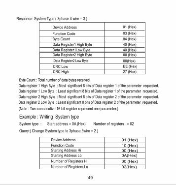
Byte Count : Total number of data bytes received.
Data register 1 High Byte : Most signicant 8 bits of Data register 1 of the parameter requested.Data register 1 Low Byte : Least signicant 8 bits of Data register 1 of the parameter requested.
Data register 2 High Byte : Most signicant 8 bits of Data register 2 of the parameter requested.
(Note : Two consecutive 16 bit register represent one parameter.)
Data register 2 Low Byte : Least signicant 8 bits of Data register 2 of the parameter requested.
Example : Writing System type
System type : Start address = 0A (Hex) Number of registers = 02
Query:( Change System type to 3phase 3wire = 2 )
01 (Hex)
10 (Hex)
Device Address
Function Code
00 (Hex)Starting Address Hi
0A(Hex)Starting Address Lo
00 (Hex)Number of Registers Hi
02(Hex)Number of Registers Lo
Device Address
Function Code
Byte Count
Data Register1 High Byte
01 (Hex)
03 (Hex)
04 (Hex)
40 (Hex)
Data Register1Low Byte 40 (Hex)
Response: System Type ( 3phase 4 wire = 3 )
49

04 (Hex)Byte Count
40 (Hex)Data Register-1High Byte
00(Hex)Data Register-1 Low Byte
00(Hex)
00(Hex)
66 (Hex)
10 (Hex)
Data Register-2 Low Byte
CRC High
CRC Low
Data Register-2 High Byte
Byte Count : Total number of data bytes received.
Data register 1 High Byte : Most signicant 8 bits of Data register 1 of the parameter requested.Data register 1 Low Byte : Least signicant 8 bits of Data register 1 of the parameter requested.
Data register 2 High Byte : Most signicant 8 bits of Data register 2 of the parameter requested.
(Note : Two consecutive 16 bit register represent one parameter.)
Data register 2 Low Byte : Least signicant 8 bits of Data register 2 of the parameter requested.
Response:
Device Address
Function Code
Start Address High
Start Address Low
Number of Registers Hi
01 (Hex)
10 (Hex)
00 (Hex)
0A(Hex)
00 (Hex)
Number of Registers Lo 02(Hex)
CRC Low 61 (Hex)
CRC High CA (Hex)
50

Start Address High : Most signicant 8 bits of starting address of the parameter requested.
Start Address low :Least signicant 8 bits of starting address of the parameter requested.
Number of register Hi : Most signicant 8 bits of Number of registers requested.
Number of register Lo : Least signicant 8 bits of Number of registers requested.
(Note : Two consecutive 16 bit register represent one parameter.)
Table 5 : 4 X register addresses
Address(Register)
ParameterNo.
ParameterModbus Start Address HexHigh Byte Low Byte
40007 4 Sys Voltage 00 06
Read / Write
R
40009 5 Sys Current 00 08R
6 Sys Type 00 0A40011 R/Wp
00 0C
40019
7 Pulse Width R/Wp
0040015 8
RS 485 Set-up Code R/Wp
00 1440021 11 Node Address.
00 1640023 12 Pulse Divisor R/Wp
00 1840025 13 Min Reset Wp
00 1A40027 14 Max Reset Wp
00 1C40029 15 Analog Out 1- Para sel R/Wp
00 1E40031 16 Analog Out 2- Para sel R/Wp
00 2040033 17 R/Wp
00 2240035 18 CT Primary R/Wp
3 00 0440005 R/Wp Energy on RS485
. R/Wp0010
40013
Reset parameters W Wp
PT Primary
0E
12
51

40039 20 - 00 26
Address(Register)
ParameterNo.
ParameterModbus Start Address HexHigh Byte Low Byte
Read / Write
00 2440037 19 System Power R
40041 21 00 28Register Order/Word Order R/Wp
2240043 R/WpCT Secondary
PT Secondary00 2A
00 2C40045 23 R/Wp
00 3040049 25
Pulse2 Parameter select
R/Wp
00 3C40061 31 R/Wp
00 4640071 36 Password R/W
00 4E40079 40 30mA Noise Current Elimination R/Wp
Pulse1 Parameter select
Energy digit reset count R/Wp
00 5040081 41 Energy Update Rate R/Wp
00 5240083 42 Model Number R40107
40109
40111
40113
54
55
56
57
58
60
61
62
Wh Import Start Count
Wh Export Start Count
Varh Import Start Count
Varh Export Start Count
Vah Start Count
Wh Import Overow Start Count
Wh Export Overow Start Count
Varh Import Overow Start
R/Wp
R/Wp
R/Wp
R/Wp
R/Wp
R/Wp
R/Wp
R/Wp
00
00
00
00
0000
00
00
6A
6C
6E
70
7276
78
7A
40115
4011940121
40123
63
64
Varh Export Overow Start
Vah Overow Start Count
R/Wp
R/Wp
00
00
7C
7E
40125
40127
Count
Count
Auto Scroll40077 39 R/W 00 4C
52

Explanation for 4 X register :
Address Parameter Description
40005
40007 System Voltage This address is read only and displays System Voltage
40009 System Current This address is read only and displays System Current
This address is used to set the System type. Write one of the following value to this address.1 = 1 Phase 2 Wire (Read only for 1P2W)2 = 3 Phase 3 Wire 3 = 3 Phase 4 Wire.Writing any other value will return error .
40011 System Type
40013 Pulse Width of Relay
This address is used to set pulse width of the Pulse output. Write one of the following values to this address: 60 : 60 ms 100 : 100 ms 200 : 200 ms Writing any other value will return error .
40015 ResetParameters
This address is used to reset the parameters by writing following. 0 : Energy reset 2 : Sys. Min reset 3 : Sys. Max reset 6 : Reset all.
Writing any other value will return an error.
Energy display on Modbus
This address is used to set energy display on MODBUS in Wh, KWh & Mwh. Write one of the following value to this address.1 = Energy in Wh. 2 = Energy in KWh. 3 = Energy in MWh.
53

Address Parameter Description
40019 Rs485 Set-upCode
This address is used to set the baud rate, Parity, Number of stop bits. Refer to Table 6 for details.
40021 Node Address
This register address is used to set Device address between 1 to 247 .
40023 Pulse Divisor
40025 Min - Reset This address is used to reset the Min parameters value. Write Zero value to this register to reset the Min parameters. Writing any other value will return an error.
40027 Max - Reset This address is used to reset the Max parameters value. Write Zero value to this register to reset the Max parameters. Writing any other value will return an error.
This address is used to set pulse divisor of the Pulse output. Write one of the following values to this address for Wh: 1 : Divisor 1 10 : Divisor 10 100 : Divisor 100 1000 : Divisor 1000 & in KWh & MWh Divisior will be 1 default. Writing any other value will return an error.Pulse rate divisor is set to 1, when Energy on Rs485 is set to kWh or MWh.
40029 Analog Out 1-Para Set
This address is used to set the parameter for Analog Output 1.Write one of the parameter no. As per the options given in Table 2 for Analog Output Parameters.Writing any other value will return an error.
40031 Analog Out 2-Para Set
This address is used to set the parameter for Analog Output 2..Write one of the parameter no. As per the options given in Table 2 for Analog Output Parameters.Writing any other value will return an error.
54

Address Parameter Description
40037 Sys Power System Power (Read Only) is the Nominal system power based on the values of Nominal system volts and Nominal system current.
40041 Word Order Word Order controls the order in which the receives instrument or sends oating - point numbers:- normal or reversed registerorder.In normal mode, the two registers that make up a oating point numbers are sent most signicant bytes rst.In reversed register mode , the two registers that make up a oating point numbers are sent least signicant bytes rst.To set the mode, write the value ‘2141.0’ into this register-the instrument will detect the order used to send this value and set that order for all ModBus transaction involving oating point numbers.
This address allows the user to set CT Primary value.The maximum settable value is 9999 & also depends on the per phase 666.6MVA Restriction of power combined with PT primary
40035 CT Pimary
40039
40033 PT Primary This address allows the user to set PT Primary value.The maximum settable value is 692.8kV L-L depends on the per phase 666.6MVA Restriction of power combined with CT primary
This address is used to set the rollover count for energy. IfEnergy on Rs485 is in Wh rollover count can be from 7 to 14.If it is in KWh then rollover count can be from 7 to 12 & for MWh rollover count can be from 7 to 9.
Energy digit Reset Count
55
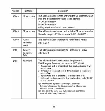
Address Parameter Description
40049 Pulse 1 parameterselect
40045 PT secondary This address is used to read and write the PT secondary value.The valid range for PT Secondary is 100 VLL to 600 VLL.
This address is used to assign the Parameter to Relay1
refer table 7.
40043 CT secondary This address is used to read and write the CT secondary valuewrite one of the following values to this address.1=1A CT secondary5=5A CT secondarywriting any other value will return an error.
40061 Pulse 2Parameter
This address is used to assign the Parameter to Relay2
refer table 7.
40071 Password This address is used to set & reset the password. Valid Range of Password can be set is 0000 - 9999 .1) If password lock is present & if this location is read it will return zero.2) If Password lock is absent & if this location is read it will return One.3) If password lock is present & to disable this lock first send valid password to this location then write “0000” to this location
4) If password lock is present & to modify 4X parameter rst send valid password to this location so that 4X parameter will be accessible for modication.5) If for in any of the above case invalid password is send then meter will return exceptional error 2.
Select
56

Address Parameter Description
40079 30mA Noise current Elimination
This address is used to activate or de-activate the 30 mA noise current elimination write 0-Deactivate30 (Decimal)-ActivateWriting any other value will return an error.
40081 EnergyUpdateRate
Energy Update Rate is the time after which energy registersare updated. This time is user settable from 1 - 60 minutes.
40083 This Address is Read Only. This Address shows the ModelNumber of the meter
ModelNumber
to40117
Energy Start Count
40107 The user can set respective energy starting count in theseregisters (before the user can write values to these locationsuser needs to check register 40005 i.e Energy on RS485 andregister 40036 i.e Energy digit reset count). Valid range is 0-9999999. For E.g if Energy on RS485 is in K and Energydigit reset count is 7 the start count should be in k andvalue should be less than 7 digits.
40077 Auto Scroll
This address is used to activate or de-activate the Auto scroll setting. 0-Deactivate1 (Decimal)-ActivateWriting any other value will return an error.
57

Address Parameter Description
to40129
Energy40119 The user can set respective Energy Overow starting countin these registers. Valid range is 0-999999. Overow
Start Count
19200 NONE19200 EVEN
19200 NONE
Baud Rate Parity Stop Bit Decimal value
01
01
02 1314
12
EVEN
19200
9600
9600
9600
NONE
NONE
ODD 01
02
01
01
15
08
09
10ODD9600
4800
4800NONE
NONE48004800
2400
2400
2400
2400
NONE
NONE
ODD
EVEN
ODDEVEN
02
01
01
01
0201
01
01
01 11
04
05
06
07
00
01
0203
NOTE : Codes not listed in the table above may give rise to unpredictable results including loss of communication. Excise caution when attempting to change mode via direct Modbus writes.
Table 6 : RS 485 Set-up Code
58
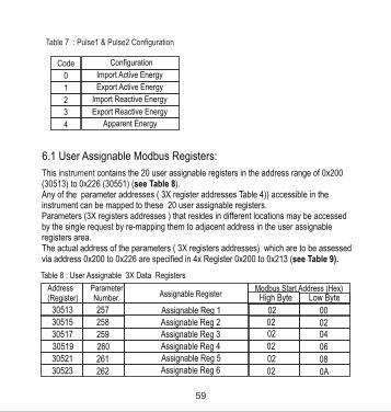
6.1 User Assignable Modbus Registers:
This contains the 20 user assignable registers in the address range of 0x200 instrument(30513) to 0x226 (30551) (see Table 8).Any of the parameter addresses ( 3X register addresses Table 4)) accessible in the instrument can be mapped to these 20 user assignable registers.Parameters (3X registers addresses ) that resides in different locations may be accessed by the single request by re-mapping them to adjacent address in the user assignable registers area. The actual address of the parameters ( 3X registers addresses) which are to be assessed via address 0x200 to 0x226 are specied in 4x Register 0x200 to 0x213 (see Table 9).
30513 257 00
Modbus Start Address (Hex)
Assignable Reg 130515 258 0202Assignable Reg 2
30517 259 0402Assignable Reg 3
30519 260 0602Assignable Reg 4
30521 261 0802Assignable Reg 5
30523 262 0A02Assignable Reg 6
Table 8 : User Assignable 3X Data Registers
Address(Register)
ParameterNumber. Assignable Register
02
High Byte Low Byte
Table 7 : Pulse1 & Pulse2 Conguration
4
Export Reactive Energy
Apparent Energy
Import Reactive Energy
Code
1
0
2
3
Conguration
Import Active Energy
Export Active Energy
59
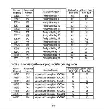
30533 267 1402Assignable Reg 11
30535 268 1602Assignable Reg 12
30537 269 1802Assignable Reg 13
30539 270 1A02Assignable Reg 14
30541 271 1C02Assignable Reg 15
30543 272 1E02Assignable Reg 16
30545 273 2002Assignable Reg 17
30547 274 2202Assignable Reg 18
30549 275 2402Assignable Reg 19
30551 276 2602Assignable Reg 20
Modbus Start Address (Hex)
30525 263 0C02Assignable Reg 7
30527 264 0E02Assignable Reg 8
30529 265 1002Assignable Reg 9
Address(Register)
ParameterNumber. Assignable Register High Byte Low Byte
30531 266 1202Assignable Reg 10
Table 9 : User Assignable mapping register ( 4X registers)
40514 258 Mapped Add for register #0x0202 02 01
40515 259 Mapped Add for register #0x0204 02 02
260 Mapped Add for register #0x0206 02 034051602 0440517 261 Mapped Add for register #0x0208
02 0540518 262 Mapped Add for register #0x020A
0640519 263 Mapped Add for register #0x020C 02
0740520 264 Mapped Add for register #0x020E
0040513 257 Mapped Add for register #0x0200 02
02
Modbus Start Address (Hex)Address(Register)
ParameterNumber. Mapping Register High Byte Low Byte
60
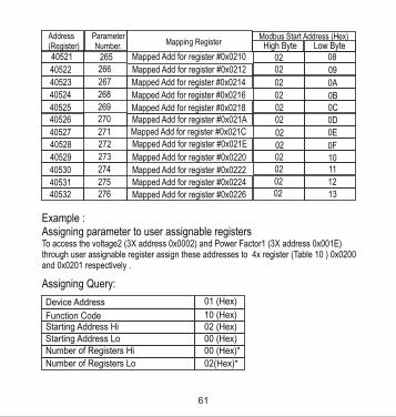
02 0840521 265 Mapped Add for register #0x0210
0902
0A02
40522 266 Mapped Add for register #0x0212
40523 267 Mapped Add for register #0x0214
Modbus Start Address (Hex)Address(Register)
ParameterNumber. Mapping Register High Byte Low Byte
0B02
0C02
0D02
0E02
0F02
1002
1102
1202
1302
40524 268 Mapped Add for register #0x0216
40525 269 Mapped Add for register #0x021840526 270 Mapped Add for register #0x021A
40527 271 Mapped Add for register #0x021C
40528 272 Mapped Add for register #0x021E
40529 273 Mapped Add for register #0x0220
40530 274 Mapped Add for register #0x0222
40531 275 Mapped Add for register #0x0224
40532 276 Mapped Add for register #0x0226
Example :Assigning parameter to user assignable registersTo access the voltage2 (3X address 0x0002) and Power Factor1 (3X address 0x001E) through user assignable register assign these addresses to 4x register (Table 10 ) 0x0200 and 0x0201 respectively .
Assigning Query:
01 (Hex)Device Address
10 (Hex)Function Code02 (Hex)Starting Address Hi00 (Hex)Starting Address Lo00 (Hex)*Number of Registers Hi
02(Hex)*Number of Registers Lo
61

00 (Hex)1E (Hex)CB (Hex)
07 (Hex)
00 (Hex)
04 (Hex)
02 (Hex)
Data Register-2 Low Byte
Byte Count
CRC High
Data Register-1 Low Byte
Data Register-2 High Byte
Data Register-1High Byte }Voltage 2 *(3X Address 0x0002)
Power Factor 1 *(3X Address 0x001E)
}CRC lOW
Reading Parameter data through User Assignable Registers:
In assigning query Voltage2 and Power Factor1 parameters were assigned to 0x 200 and 0x201(Table10) which will point to user assignable 3xregisters 0x200 and 0x202 (table9). So to read Voltage2 and PowerFactor1 data reading query should be as below.
Device Address
Function CodeStart Address High
Start Address Low
Number of Registers HiNumber of Registers Lo
CRC Low
CRC High
01 (Hex)
10 (Hex)
02 (Hex)
00 (Hex)
00 (Hex)02 (Hex)
40 (Hex)
70 (Hex)
Response :
62
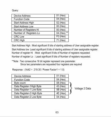
Query:
Device Address
Function Code
Start Address High
Start Address LowNumber of Registers HiNumber of Registers Lo
CRC Low
CRC High
01 (Hex)04 (Hex)
02 (Hex)
00 (Hex)
00 (Hex)04 (Hex) **F0 (Hex)
71 (Hex)
Start Address High : Most signicant 8 bits of starting address of User assignable register.
Start Address low :Least signicant 8 bits of starting address of User assignable register. Number of register Hi : Most signicant 8 bits of Number of registers requested.
Number of register Lo : Least signicant 8 bits of Number of registers requested.
**Note : Two consecutive 16 bit register represent one parameter. Since two parameters are requested four registers are required
Response : (Volt2 = 219.30 / Power Factor1 = 1.0)
01 (Hex)
04 (Hex)
Device Address
Function Code08 (Hex)
43 (Hex)5B (Hex)
4E (Hex)
Byte count
} Voltage 2 DataData Register-1 Low Byte
Data Register-2 High Byte
Data Register-1High Byte
04 (Hex)Data Register-2 Low Byte
63

User Assignable mapping Registers ( 4X Registers Table10 )
Voltage 2 (0x0002)
Power Factor 1 (0x001E)
Wh Import (0x0048)
Frequency (0x0046)
VAh (0x0050)
Current 1 (0x0006)
User Assignable Data Registers ( 3X Registers Table 9 )
0x200 (16 bit)
0x201(16 bit)
0x203(16 bit)
0x202(16 bit)
0x204(16 bit)
0x205(16 bit)
0x206(16 bit)
0x207(16 bit)
0x224(16 bit)
0x225(16 bit)
0x226(16 bit)
0x227(16 bit)
0x200
0x202
0x204
0x206
0x224
0x226
0x200
0x201
0x202
0x203
0x212
0x213
(Starting Address)
}00 (Hex)00 (Hex)79 (Hex)
3F (Hex)
3F (Hex)80 (Hex)
Data Register-4 Low Byte
CRC High
CRC Low
Data Register-3 Low Byte
Data Register-4 High Byte
Data Register-3 High Byte
Power Factor 1Data
(Starting Address)
64

7.Phasor Diagram :
To get the data through User assignable Register use following steps:1) Assign starting addresses(Table3) of parameters of interest to a “User assignable mapping registers” in a sequence in which they are to be accessed (see section “Assigning parameter to user assignable registers”) 2) Once the parameters are mapped data can be acquired by using “User assignable data register “ Starting address . i.e to access data of Voltage2, Power factor1,Wh import, Frequency send query with starting address 0x200 with number of register 8 or individually parameters can be accessed for example if current1 to be accessed use starting address 0x212. (See section Reading Parameter data through User Assignable Registers)
InductiveCapacitive
Capacitive Inductive90 degrees (0.000)
0 degrees (+1.000)180 degrees (-1.000)
270 degrees (0.000)
-+
2
4+-
65

Connections Quadrant
Power ( P )
Sign of Active
Power ( Q )
Sign of Reactive
Factor ( PF )
Sign of Power
Inductive /Capacitive
Import 1 + P + Q + L
Import 4 + P - Q + C
Export 2 - P + Q - C
Export 3 - P - Q - L
Inductive means Current lags VoltageCapacitive means Current leads Voltage
8. Installation
Mounting is by four side clamps, slide the side clamps through side slot till side clamp gets rmly locked in a groove (Refer g.) Consideration should be given to the space required behind the instrument to allow for bends in the connection cables.
SLIDE IN THIS DIRECTION AND LOCKPANEL
Meter
When the instrument displays Active power ( P )with “ + ” ( positive sign ) ,
the connection is “ Import ” .
When the instrument displays Active power ( P )with “ - ” ( negative sign ) ,
the connection is “ Export ” .
66

8.1 EMC Installation RequirementsThis product has been designed to meet the certication of the EU directives when installed to a good code of practice for EMC in industrial environments, e.g.
1. Screened output and low signal input leads or have provision for tting RF suppression components, such as ferrite absorbers, line lters etc., in the event that RF elds cause problems.
Note: It is good practice to install sensitive electronic instruments that are performing critical functions, in EMC enclosures that protect against electrical interference which could cause a disturbance in function.
2. Avoid routing leads alongside cables and products that are, or could be, a source of
Caution1. In the interest of safety and functionality this product must be installed by
a qualified engineer, abiding by any local regulations.
2. Voltages dangerous to human life are present at some of the terminal connections of this unit. Ensure that all supplies are de-energised before attempting any connection or disconnection.
3. These products do not have internal fuses therefore external fuses must be used to ensure safety under fault conditions.
As the front of the enclosure conforms to IP54 it is protected from water spray from all directions, additional protection to the panel may be obtained by the use of an optional panel gasket.
The terminals at the rear of the product should be protected from liquids.
The instrument should be mounted in a reasonably stable ambienttemperature and where the operating temperature is within the range
0-10 to 55 C . Vibration should be kept to a minimum and the product should not be mounted where it will be subjected to excessive direct sunlight.
interference.
67
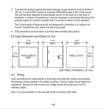
4. ESD precautions must be taken at all times when handling this product.
3. To protect the product against permanent damage, surge transients must be limited to 2kV pk. It is good EMC practice to suppress differential surges to 2kV at the source. The unit has been designed to automatically recover in the event of a high level of transients. In extreme circumstances it may be necessary to temporarily disconnect the auxiliary supply for a period of greater than 5 seconds to restore correct operation.
The Current inputs of these products are designed for connection in to systems via Current Transformers only, where one side is grounded.
8.2 Case Dimension and Panel Cut Out
3.78”96mm
FRONT DISPLAYAREA
3.78”96mm
3.15”80mm
3.62”92mm
PANEL CUTOUT3.62”92mm
MAX PANEL THICKNESS 0.18”,5mm
8.3 WiringInput connections are made directly to screw-type terminals with indirect wire pressure. Numbering is clearly marked in the plastic moulding. Choice of cable should meet local
2regulations. Terminal for both Current and Voltage inputs will accept upto 3mm x 2 diameter cables.
Note : It is recommended to use wire with lug for connection with meter.
68
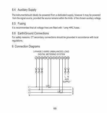
9. Connection Diagrams
3-PHASE 3-WIRE UNBALANCED LOADDIGITAL METERING SYSTEM
P1 S1
P1 S1
L NAUX
SUPPLY
L1 L2L3N
L OAD
2 5 8 3 4 6 7 9
8.4 Auxiliary Supply
The should ideally be powered from a dedicated supply, however it may be powered instrument from the signal source, provided the source remains within the limits of the chosen auxiliary voltage.
8.5 FusingIt is recommended that all voltage lines are tted with 1 amp HRC fuses.
8.6 Earth/Ground ConnectionsFor safety reasons, CT secondary connections should be grounded in accordance with local
regulations.
69

3-PHASE 4-WIRE UNBALANCED LOADDIGITAL METERING SYSTEM
2 5 8 11 1 3 4 6 7 9 13 14
L NAUX
SUPPLY
P1 S1
S1P1
P1 S1
L1 L2L3N
L OAD
SINGLE PHASEDIGITAL METERING SYSTEM
P1 S1
L NAUX
SUPPLY
L
N
L OAD
2 3
70

System CT primary values Std. Values from 1 to 9999A
InputsNominal input voltage (AC RMS)
Max continuous input voltage
Max short duration input voltage
Nominal input voltage burden
Phase-Neutral 57.7 - 346 VL-N
L-L
120% of Rated Value
2 x Rated Value(1s application repeated 10 times
at 10s intervals)
0 .35 VA approx. per phase
Max continuous input current 120% of Rated Value
Nominal input current burden 0 .3VA approx. per phase
Max short duration current input 20 x Rated Value (1s application repeated 5 times at 5 min. intervals)
Nominal input current 1A / 5A AC rms
(1 or 5 Amp secondaries)
Line-Line 100 - 600 V
10. Specication :
System 3 Phase 3 Wire / 3 phase 4 Wire programmable at site
Auxiliary
Standard nominal Auxillary supply voltages & Frequency
a.c. supply frequency range 45 to 66 Hz
60 - 300 V AC- DC OR 65 - 300 V AC- DC with Ethernet / Analog Output
a.c. supply burden 5 VA approx.
d.c. supply burden 4 W approx.
12 - 60 V AC - DC
7 VA approx. with Ethernet / Analog Output
5 W approx. with Ethernet / Analog Output
1 Phase 2 Wire as per order
71

Power Factor 1 % of Unity
Frequency 40 .. 70 HzPower Factor 0.5 Lag ... 1 ... 0.8 Lead
Accuracy
Voltage 0.5 % of range
C urren t 0.5 % of range
Frequency 0.15% of mid frequency
Active Energy 1.0 % of range
0.5 % of range Active Power 0.5 % of range Re- Active Power 0.5 % of range Apparent Power
Apparant Energy 1.0 % of range
Accuracy 1:
Re - Active Energy 1.0 % of range
Current 5 .. 120 % of Rated Value
Angle 1 % of range
Analog Output 1 % of Output end value
Total Harmonic DistortionNeutral Current 4 % of range.
Accuracy 0.5:Voltage 0.5 % of range C urren t 0.5 % of range Frequency 0.15% of mid frequency
Active Energy 0.5 % of range
0.5 % of range Active Power 0.5 % of range Re- Active Power 0.5 % of range Apparent Power
1 %
Operating Measuring RangesVoltage 10 .. 120 % of Rated Value
72

Reference conditions for Accuracy : 0 023 C + 2 C
50 or 60Hz ± 2%
Reference temperatureInput frequency
Power Factor 1 % of UnityAngle 1 % of range
Analog Output 1 % of Output end value
Total Harmonic DistortionNeutral Current 4 % of range
Vo ltage
C urren t
± 0.2 % of range ± 0.2 % of range
Frequency 0.15% of mid frequency
Active Energy ± 0.2 % of range
± 0.2 % of range Active Power± 0.4 % of range Re- Active Power± 0.2 % of range Apparent Power
Re - Active Energy Apparant Energy ± 0.2 % of range
Power Factor ± 1 % of Unity
Angle ± 1 % of range
Analog Output ± 1 % of Output end value
Total Harmonic Distortion ± 1 %
Accuracy 0.2:
± 0.5 % of range
Neutral Current ± 4 % of range
Sinusoidal (distortion factor 0.005)Input waveform
Rated Value + 1 %Auxiliary supply voltage
Auxiliary supply frequency Rated Value + 1 %Voltage Range 50... 100% of Nominal Value.
60... 100% of Nominal Value for THD.
1 %
Apparent Energy 0.5 % of rangeRe - Active Energy 0.5 % of range
73

74
Current Range 10... 100% of Nominal Value.
Power cosØ / sinØ = 1
10... 100% of Nominal Current &50... 100% of Nominal Voltage.
For Active / Reactive Power & Energy
20... 100% of Nominal Value for THD.
Power Factor / Phase Angle 40... 100% of Nominal Current &
50... 100% of Nominal Voltage.
Nominal range of use of inuence quantities for measurands
50 .. 120 % of Rated Value10 .. 120 % of Rated ValueRated Value + 10 %
00 to 50 C
VoltageCurrent
Input frequency Temperature
Auxiliary supply voltage
Auxiliary supply frequency
Rated Value + 10 %
Rated Value + 10 %
Temperature Coefcient0
0.025% / C for Voltage (50..120% of Rated Value) (For Rated value range of use 00.05% / C for Current ( 10..120% of Rated Value )
00... 50 C )
Error change due to variation of an inuence quantity
2 * Error allowed for the referencecondition applied in the test.
Approx. 1 seconds Update
Display
3 Line 4 Digits, (Digit Height 11mm) LED
ControlsTwo Push ButtonsUser Interface

Standards
IEC 61326
10V/m min-Level 3 industrial low level
electromagnetic radiation environment
IEC 61000-4-3.
IEC 61010-1 , Year 2001
EMC Immunity
Safety
IEC 60529IP for water & dust
Isolation2.2 kV RMS 50 Hz for 1 minutebetween all electrical circuits
Dielectric voltage withstandtest between circuits andaccessible surfaces
Environmental0-10 to 55 C
0-20 to +65 C
0 .. 90 % RH 3 minute (minimum)
15g in 3 planes
10 .. 55 Hz, 0.15mm amplitude
IP 54 as per IEC 60529
Operating temperatureStorage temperature
Relative humidity
Warm up time
Shock
Vibration
Enclosure ( front only )
Enclosure
96mm x 96mm DIN QuadraticStyle
Polycarbonate Housing ,Material
Self extinguish & non dripping as per UL 94 V-0 Screw-type terminals Terminals
< 80 mm Depth
0.620 kg Approx.Weight
75

Pulse output Option ( 1 or 2 Relay ) :1NO + 1NCRelay240VDC , 5Amp.Switching Voltage & CurrentSwitching Voltage & Current
1 per Wh (up to 3600W), 1 per kWh (up to 3600kW), 1 per MWh (above 3600 kW)
Default Pulse rate Divisor
Pulse rate Divisors Programmable on site1 per 10Wh (up to 3600W), 1 per 10kWh (up to 3600kW), 1 per 10MWh (above 3600 kW)
10
1 per 100Wh (up to 3600W), 1 per 100kWh (up to 3600kW), 1 per 100MWh (above 3600 kW)
100
1 per 1000Wh (up to 3600W), 1 per 1000kWh (up to 3600kW), 1 per 1000MWh (above 3600 kW)
1000
60ms , 100ms or 200msPulse DurationNote : Above conditions are also applicable for Reactive & Apparent Energy .
ModBus ( RS 485 ) Option :
ModBus ( RS 485 )Protocol
19200 , 9600 , 4800 or 2400Baud Rate( Programmable )
Odd or Even, with 1 stop bit,ParityOr None with 1 or 2 stop bits
Note : Pulse rate divisor is set to 1, when Energy on Rs485 is set to kWh or MWh.
Analog Output Option :0 ... 1mA dc into 0 - 2 kohmLinear Uni-directional, internally powered .
4 ... 20mA dc into 0 - 500 ohmUni-directional, internally powered.
76
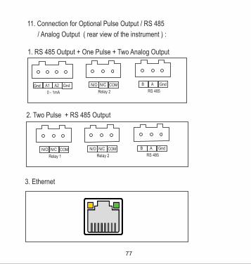
11. Connection for Optional Pulse Output / RS 485
/ Analog Output ( rear view of the instrument ) :
1. RS 485 Output + One Pulse + Two Analog Output
A1 A2 Gnd
0 - 1mA
N/O N/C COM
Relay 2
B A Gnd
RS 485 Gnd
2. Two Pulse + RS 485 Output
N/O N/C COM
Relay 1
N/O N/C COM
Relay 2
B A Gnd
RS 485
3. Ethernet
77
The Information contained in these installation instructions is for use only by installers trained to make electrical power installations and is intended to describe the correct method
It is the user's responsibility to determine the suitability of the installation method in the
of installation for this product.
user’s eld conditions.
78


![Drehstromzähler für gewerbliche, industrielle und ... · 500 Imp./kWh [kvarh] 250 Imp./kWh [kvarh] 10 000 Imp./kWh [kvarh] 5 000 Imp./kWh [kvarh] Messarten +P, ‑P, +Q, ‑Q, Q1,](https://static.fdocuments.net/doc/165x107/5d4ed32288c99342288b7ae9/drehstromzaehler-fuer-gewerbliche-industrielle-und-500-impkwh-kvarh.jpg)