Operating Manual - PSP 606 (Volume 2) - · PDF fileAlert Annunciator Vertical Mode Annunciator...
47
canadair chauenQer OPERATING MANUAL SECTION 4 AUTOMATIC FLIGHT CONTROL SYSTEM TABLE OF CONTENTS Subject ZiSi GENERAL 1 FLIGHT DIRECTOR SYSTEM 1 AIR DATA SYSTEM 2 AUTOPILOT SYSTEM '- STABILITY AUGMENTATION SYSTEM ? Yaw Damping Mach Trim FLIGHT DIRECTOR COMPONENTS 7 Attitude Director Indicator Horizontal Situation Indicator Remote Heading and Course Select Controller Flight Director Mode Selector Flight Director Computer $ Rate Gyro Vertical Gyro Directional Gyro Instrument Comparator Touch Control Steering AIR DATA COMPONENTS 3 Air Data Computer Pilot's Altimeter 9 Pilot f s Vertical Speed Indicator Pilot's Mach/Airspeed Indicator TAS/SAT/TAT Indicator VNAV Computer/Controller RIGHT COMPARTMENT DISPLAYS 9 Attitude Director Indicator Attitude Sphere Aircraft Symbol 12 Roll Attitude Pointer Eyelid Display Pitch and Roll Command Bar Flight Director Warning Flag Glideslope Pointer Glideslope Warning Flag 4 - CONTENTS Page 1 Oct 03/83
Transcript of Operating Manual - PSP 606 (Volume 2) - · PDF fileAlert Annunciator Vertical Mode Annunciator...

canadair chauenQer
OPERATING MANUAL
SECTION 4
AUTOMATIC FLIGHT CONTROL SYSTEM
TABLE OF CONTENTS
S u b j e c t ZiSi
GENERAL 1
FLIGHT DIRECTOR SYSTEM 1
AIR DATA SYSTEM 2
AUTOPILOT SYSTEM '-
STABILITY AUGMENTATION SYSTEM ? Yaw Damping Mach T r i m
FLIGHT DIRECTOR COMPONENTS 7 Attitude Director Indicator Horizontal Situation Indicator Remote Heading and Course Se lec t Controller Flight Director Mode Selector Fl ight Director Computer $ Rate Gyro Vertical Gyro Directional Gyro Instrument Comparator Touch Control Steering
AIR DATA COMPONENTS 3 Air Data Computer P i l o t ' s Altimeter 9 P i l o t f s Vert ical Speed Indicator P i l o t ' s Mach/Airspeed Indicator TAS/SAT/TAT Indicator VNAV Computer/Controller
RIGHT COMPARTMENT DISPLAYS 9 Attitude Director Indicator
Attitude Sphere Aircraft Symbol 12 Roll Att i tude Pointer Eyelid Display Pitch and Roll Command Bar Fl ight Director Warning Flag Glideslope Pointer Glideslope Warning Flag
4 - CONTENTS Page 1
Oct 03/83
canatiair chaiienQer
OPERATING MANUAL
Subject Page
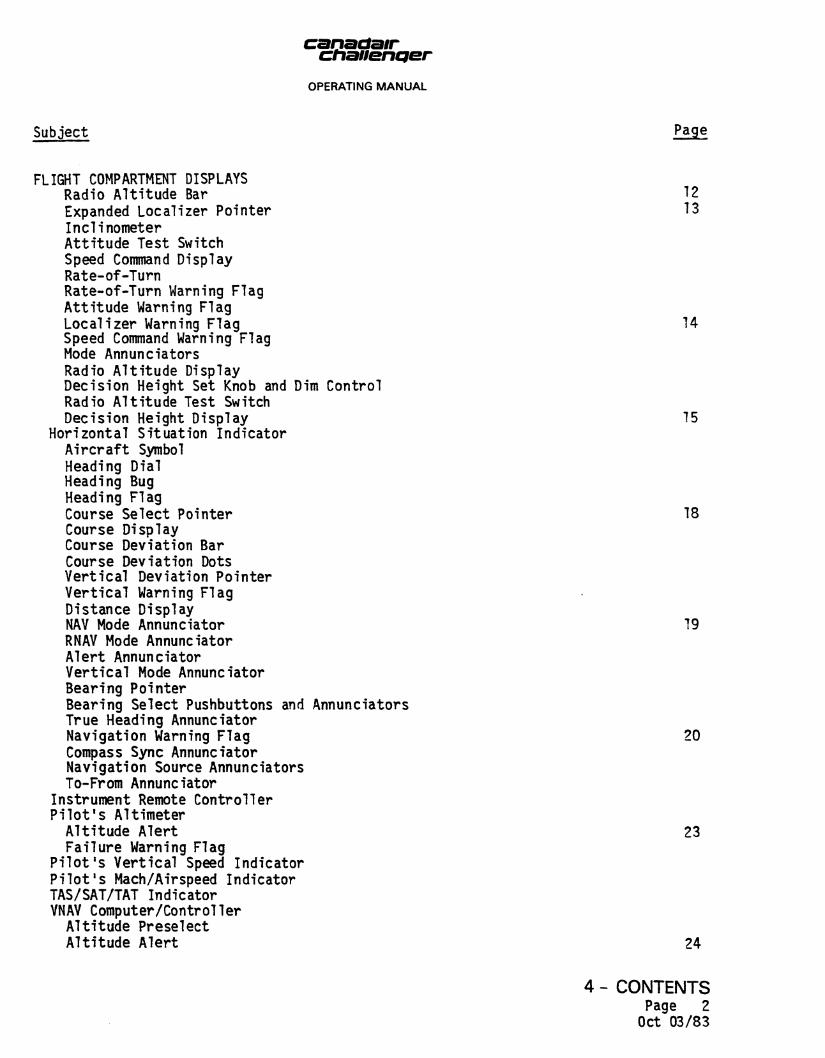
FLIGHT COMPARTMENT DISPLAYS Radio Altitude Bar 12 Expanded Localizer Pointer 13 Inclinometer Attitude Test Switch Speed Command Display Rate-of-Turn Rate-of-Turn Warning Flag Attitude Warning Flag Localizer Warning Flag 14 Speed Command Warning Flag Mode Annunciators Radio Altitude Display Decision Height Set Knob and Dim Control Radio Altitude Test Switch Decision Height Display 15
Horizontal Situation Indicator Aircraft Symbol Heading Dial Heading Bug Heading Flag Course Select Pointer 18 Course Display Course Deviation Bar Course Deviation Dots Vertical Deviation Pointer Vertical Warning Flag Distance Display NAV Mode Annunciator 19 RNAV Mode Annunciator Alert Annunciator Vertical Mode Annunciator Bearing Pointer Bearing Select Pushbuttons and Annunciators True Heading Annunciator Navigation Warning Flag 20 Compass Sync Annunciator Navigation Source Annunciators To-From Annunciator
Instrument Remote Controller Pilot's Altimeter Altitude Alert 23 Failure Warning Flag
Pilot's Vertical Speed Indicator Pilot's Mach/Airspeed Indicator TAS/SAT/TAT Indicator VNAV Computer/Controller Altitude Preselect Altitude Alert 24
4 -Page Oct

canadair chauenQer
OPERATING MANUAL
Subject fii?
FLIGHT COMPARTMENT DISPLAYS Vertical Navigation Computation 24 Vertical Path Flying 29 Vertical Input Cancelling
Instrument Comparator
SYSTEM CONTROLS 29 Flight Director Mode Selector
Heading Select Mode 30 Navigation Mode VOR Mode VOR Approach Mode 33 RNAV Mode Localizer Mode Back Course Mode Localizer Approach Mode 34 Pitch Hold Mode Altitude Hold Mode Indicated Airspeed Hold Mode 36 Vertical Speed Hold Mode Mach Hold Mode Standby Mode Altitude Prese lec t Mode 37 VNAV Mode Go-Around Mode Touch Control Steering
Autopilot Controller 33 Yaw Damper Engage Autopilot Engage Turn Knob Pitch Hold Couple 41 Soft Ride
FAILURE MONITORING AND STATUS ANNUNCIATION 41 Failure Warnings Autopilot Se l f -Test 43
4 -Page
Oct

canadsir chanentjer
OPERATING MANUAL
LIST OF ILLUSTRATIONS
Figure Number Title Page
1
2
3
4
5
6
7
8
9
10
11
12
13
14
15
16
17
AFCS Flight Compartment Contro"
Stability Augmentation Control
Attitude Director Indicator (2
Horizontal Situation Indicator
Instrument Remote Controller
Altimeter
Vertical Speed Indicator
Mach/Airspeed Indicator
TAS/SAT/TAT Indicator
VNAV Computer/Controller
Instrument Comparator
Flight Director Mode Selector
Control Wheel
Throttle Actuating Lever
Autopilot Controller
Warning and Disengage Lights
Autopilot Status Panel
Is and Indicators
Panel
Sheets)
(2 Sheets)
3/4
6
10
16
21
22
25
25
27
28
31
32
35
39
40
42
44
canaaair chauencier
OPERATING MANUAL
SECTION 4
AUTOMATIC FLIGHT CONTROL SYSTEM
GENERAL (Figure 1)
The automatic f l i g h t control system (AFCS) provides three -ax i s f l i g h t contro l , guidance and s t a b i l i z a t i o n using dual-channel computations to drive dual servos in the r o l l , pitch and yaw axes. The AFCS comprises two complete f l i g h t director systems, an a ir data system, a two-channel autop i lo t and a s t a b i l i t y augmentation system, including yaw damping and Mach tr im.
When engaged and coupled to the f l i g h t d i r e c t o r s , the autop i lo t controls the a i rcra f t using the commands generated by e i ther the p i l o t f s or c o p i l o t ' s f l i g h t director computer.
When engaged without a f l i g h t director mode s e l ec t ed , manual pitch and r o l l commands are inserted using the pitch wheel and turn knob on the autopi lot controller.
When the autopilot is coupled to the flight director, the touch control steering can be used to manoeuvre the aircraft without disengaging the autopilot.
Each channel of the three-axis AFCS is continuously monitored and i f a failure occurs i t automatically switches to single channel operation in that ax i s .
FLIGHT DIRECTOR SYSTEM
The f l ight director system comprises two complete independent systems (p i lo t f s and copi lo t ' s ) . Each system provides a full complement of horizontal and vertical fl ight guidance modes, including all radio guidance modes, RNAV tracking and air data oriented vertical modes.
Each attitude director indicator (ADD has a sphere pitch and roll attitude presentation. An annunciator panel is located at the top of each ADI to inform the pilot of mode and submode switching. These panels are constructed so that no lettering i s vis ible unless the mode i s annunciated.
Each horizontal situation indicator (HSI) operates in conjunction with a remote, pedestal mounted, heading and course select controller. Each HSI displays the aircraft's position with respect to various ground-based navigational aids.
SECTION 4 Page 1
Oct 03/83

canadair cftanenQer
OPERATING MANUAL
AIR DATA SYSTEM
The air data system receives pitot-static pressures from the pitot-static system, temperature signals from the total-air-temperature probe and a barometric setting from the pilot's altimeter. From these inputs, the air data computer (ADC) computes signals relating to altitude, vertical speed, true airspeed, Mach number and maximum operating speed that are used to drive the pilot's altimeter, Mach airspeed indicator, vertical speed indicator, TAS/SAT/TAT indicator and VNAV computer/controller.
The ADC provides the basic altitude hold and airspeed gain programming functions, and also vertical speed, airspeed and Mach control functions to the autopilot, flight director, and stability augmentation systems. Outputs are also provided for the flap overspeed, stall warning and ATC transponder.
The pilot's altimeter provides a baro-corrected counter-drum pointer display of the aircraft altitude as determined by the air data computer. Baro set information from the altimeter is used to correct the air altitude outputs to the altimeter, VNAV computer/controller and flight director computer altitude hold functions. The vertical speed indicator provides a pointer display of vertical speed rates of 0 to +6000 feet per minute.
The Mach/airspeed indicator provides a mechanical counter display of Mach and servo-driven pointer displays of airspeed (plain white pointer) and maximum operating airspeed (orange-striped pointer) as computed in the air data computer. External bugs are provided on the perimeter of the airspeed dial and can be manually set to desired airspeed references.
The VNAV computer/controller provides for data insertion and display of altitude alerting, altitude preselect and VNAV information.
AUTOPILOT SYSTEM
The autopilot is a two-axis system designed for fail/passive operation throughout the flight regime. Duplex servos provide continuous automatic control and hardover protection following any single failure when both channels are engaged. If a failure occurs, there is no need to disengage, as there is no significant flight path deviation; the aircraft continues to track commands and the pilot is alerted that a failure has occurred. Automatic channel switching prevents aircraft reactions when an autopilot malfunction occurs during out-of-trim conditions.
STABILITY AUGMENTATION SYSTEM (Figure 2)
The stability augmentation system provides dual channel yaw damping and single channel Mach trim. The main components of the system are the stability augmentation computer, linear yaw actuators, stability augmentation control panel and a total position transducer.
SECTION 4 Page 2
Oct 03/83

OPERATING M A N U A L
PILOT'S MACH/AIRSPEED INDICATOR
O
0 AD!
EFFECTIVITY: A/C 1021 & SUBS
\
\
l@! | ^ ;
© HSI
EFFECTIVITY: A /C 1021 & SUBS
r 0 HOC WAV IOC APR CS BC @ >
HDG NAV APR BC VORAPR SBY IIJARAAJ C ARM ARM|CAPl ARM CAP I
>ALT ALTSELVNAV© VS IAS MACH©
IISI ©
FT q n 100 FT
S T g a , ,ALT
O) DIM
VANG DEC
VNAV COMPUTER CONTROLLER FLIGHT DIRECTOR MODE SELECTOR
PILOT'S ALTIMETER
© O
ADI
EFFECTIVITY: A/C 1004 TO 1020
TAS/SAT/TAT INDICATOR
— I — I j ,
I
i __ I © HSI
EFFECTIVITY: A/C 1004 TO 1020
TEST RESET
B HOC
MNTR
WARN D1SA8LE
DESCEND
a
p I T C K
f^===5)l
CLIMB/
COUPLE
1 1 | 2 I
SOFT RIDE
|ON 1
|ENGAGE[ ENGAGE 1
AP YD
COURSE I HEADING COURSE 2
• ® INSTRUMENT REMOTE CONTROLLER
INSTRUMENT COMPARATOR AUTOPILOT CONTROLLER
•PILOT'S VERTICAL SPEED INDICATOR
© ©
ROLL 1 PITCH 1 YAW1 TEST I TRIM
OFF j
ROLL 2
E3
i| O F F )
PITCH 2
EO 1 OFF |
YAW 2
[[OFF ||
[TEST]
TEST 2
[TEST|
UP DN
AUTOPILOT STATUS PANEL
(2) AFCS Flight Compartment Controls
and Indicators Figure 1
SECTION 4 Page 3/4 Oct 03/83

canactair chauencier
OPERATING MANUAL
Yaw Damping
The dual channel yaw damper performs two functions, yaw damping and turn coordination. Yaw damping improves aircraft longitudinal stability by damping oscillations in the yaw axis, which if not corrected, would induce dutch roll. Inputs are provided to the rudder for turn coordination throughout the turn. Dual channel operation provides greater yaw damping and a fail passive capability which disengages a failed channel and reverts to single channel operation without aircraft deviation from the selected flight path.
The yaw damper is automatically engaged when the autopilot is engaged. It can also be engaged by pressing the YD ENGAGE switch/light on the autopilot controller. Either channel can be switched off prior to engaging by pressing the YAW 1 OFF or YAW 2 OFF switch/light on the autopilot status panel. Single channel operation cannot be selected with the yaw damper engaged.
When a failure occurs in either channel and the monitoring circuits can determine which channel has failed, the actuator in the failed channel is driven to the middle of its travel range and a brake applied; the amber YD INOP segment of the YD INOP/YD FAIL switch/light on the stability augmentation control panel comes on; the MASTER/CAUTION PRESS TO RESET switch/light flashes; the FLT CONT light on the master caution system annunciator panel and the YAW 1 OFF or YAW 2 OFF switch/light on the autopilot status panel come on. The YD ENGAGE switch/light on the autopilot controller remains on green. The MASTER/CAUTION PRESS TO RESET, FLT CONT and YD INOP lights can be reset by pressing the MASTER/CAUTION PRESS TO RESET switch/light and YD INOP switch/light.
When a failure occurs in either channel and the monitoring circuits cannot determine which channel has failed, the red YD FAIL segment of the YD INOP/YD FAIL switch/light on the stability augmentation control panel flashes; the AFCS disengage lights on the pilot's and copilot's instrument panels flash red; the YD ENGAGE switch/light on the autopilot controller remains on green; and YAW 1/OFF and YAW 2 OFF switch/lights on the autopilot status panel flash amber. The red YD FAIL and AFCS disengage lights can only be reset by disengaging the yaw damper. Each channel is then individually engaged to determine the failed channel.
Mach Trim
Mach trim is a full-time operational system when the autopilot is not engaged. Mach trim is controlled by the MACH TRIM TEST/ON/OFF switch on the stability augmentation control panel which provides for test, normal and manual modes. If a failure of the Mach trim system occurs, backup is provided by the automatic pitch trim system of the autopilot. The Mach trim disengages if Mach hold is flown with the autopilot engaged (refer to paragraph 9, SYSTEM CONTROLS). The Mach trim automatically compensates for the pitch down attitude that occurs as the aircraft Mach number increases.
SECTION 4 Page 5 Oct 03/83

canadair chauencjer
OPERATING MANUAL
MACH TRIM INOP SWITCH/LIGHT
Amber MACH TRIM INOP light comes on if Mach trim fails. When pressed, Mach trim is re-engaged. If light remains on, MACH TRIM TEST/ON/OFF switch must be set to OFF.
SERVO MONITOR QSTAJBAjpMTN PITCH
YAW
ROLL
J
YD INOP SWITCH/LIGHT
Amber YD INOP light comes on if a yaw damper channel fails. When pressed, the light is reset.
MACH TRIM INOP
YD INOP
YD FAIL
©
MACH TRIM TEST ,
ON OFF
MACH TRIM TEST/ON/OFF SWITCH
Three-position, spring-loaded switch.
ON—Mach trim is engaged.
TEST-When held at TEST, the NUP STAB pointer on the control surface trim indicator moves up. When released, the MACH TRIM INOP light comes on, the MASTER CAUTION/ RESET switch/lights flash and the FLT CONT light on the 10-channel system annunciator comes on.
YD FAIL LIGHT
Red YD FAIL light flashes if there is a channel failure which the autopilot and stability augmentation monitors can not identify. Light can not be reset.
DISENGA
Y/D DISENGA PUSHBUTTON
When pressed, disengages yaw damper.
I Stabi l i ty Augmentation Control Panel SECTION 4
Figure 2 Page 6 Oct 03/83

canaaair chanenQer
OPERATING MANUAL
Failure of a Mach trim channel is indicated when the amber MACH TRIM INOP switch/light on the stability augmentation control panel comes on. To alert the pilots immediately of this condition, the red MASTER/CAUTION PRESS TO RESET switch/light flashes and FLT CONT light on the master caution system annunciator panel comes on. The Mach trim can be re-engaged by pressing the MACH TRIM INOP switch/light if the failure was momentary. If the failure persists the Mach trim system must be disengaged by switching the MACH TRIM TEST/ON/OFF switch to OFF.
To test the Mach trim system, the MACH TRIM TEST/ON/OFF switch is held in the TEST position and the NUP STAB (nose up pointer, stabilizer) pointer on the control surface trim indicator moves up. When the switch is released, the MACH TRIM INOP switch/light comes on, the red MASTER/CAUTION PRESS TO RESET light flashes and FLT CONT light on the master caution system annunciator panel comes on.
6. FLIGHT DIRECTOR COMPONENTS
A. Attitude Director Indicator
The ADI is an integrated attitude director indicator which displays pitch and roll attitude, flight director commands, glideslope deviation, localizer deviation, radio altitude, rate-of-turn, speed command, appropriate flags, inclinometer, attitude self-test switch, and mode annunciation.
B. Horizontal Situation Indicator
The HSI is an integrated horizontal situation indicator that displays heading, course deviation, vertical deviation, ADF or NAV bearing, selected heading, selected course with digital read-out, DME distance, waypoint alert light and appropriate annunciators and flags. The indicator also provides heading and course error signals to the flight director computer.
C. Remote Heading and Course Select Controller
The remote heading and course select controller contains a HEADING control, a COURSE 1 control and a COURSE 2 control. The HEADING control drives both the pilot's and copilot's HSI heading bugs. The COURSE 1 control drives the pilot's HSI course select pointer and the COURSE 2 control drives the copilot's HSI course select pointer.
D. Flight Director Mode Selector
The flight director mode selector contains the mode select switch/lights for selecting flight director path modes.
SECTION 4 Page 7
Oct 03/83

canadair chanentjer
OPERATING MANUAL
E. Flight Director Computer
The flight director computer contains all computation and mode selection electronics for flight director flight path modes.
F. Rate Gyro
The rate gyro drives the rate-of-turn display on the ADI and provides a damping input to the stability augmentation system.
G. Vertical Gyro
The vertical gyro provides roll and pitch data to the ADI, flight director computer, autopilot and weather radar.
H. Directional Gyro
The directional gyro provides heading data to the HSI, radio magnetic indicator, autopilot, and VHF navigation system.
I. Instrument Comparator
The instrument comparator compares information from the pilot's and copilot's instruments and VHF navigation receivers. Roll and pitch attitude, heading, glideslope and localizer deviation are also monitored. A visual warning is provided if a difference exists between any of the compared signals.
J. Touch Control Steering
Touch Control Steering (TCS) allows the pilot to momentarily take control of the aircraft without disengaging the autopilot. When the TCS button on either control wheel is pressed, the servo clutches disengage to allow the pilot or copilot to manually change the air data hold modes (IAS, ALT, VS or MACH) to a new reference or to manoeuvre the aircraft while tracking a selected flight path. When the TCS button is released, the servo clutches reengage at the manually set attitude.
7. AIR DATA COMPONENTS
A. Air Data Computer
The air data computer contains all the electronics and sensors needed to provide altitude outputs to the altitude indicator and altitude alert; air data hold errors of vertical speed, altitude, and Mach to the flight director computer and the stability augmentation system. The ADC also drives the vertical speed indicator and Mach/airspeed indicator and provides speed information for the flap overspeed and stall warning system.
SECTION 4 Page 8
Oct 03/83
canaaair chauencjer
OPERATING MANUAL
B. Pi lo t 's Altimeter
The pilot1s altimeter provides a servo-driven, counter-drum-pointer display of barometrically corrected pressure altitude. The barometric pressure is set manually with the BARO knob and displayed in units of inches of mercury and millibars. A light on the bezel is provided for altitude alert warning.
C. Pilotfs Vertical Speed Indicator
The pilot's vertical speed indicator provides a servo-driven display of vertical speed rates from 0 to +6000 feet per minute.
D. Pilot's Mach/Airspeed Indicator
The pilot's Mach/airspeed indicator provides a counter display of Mach and servo-driven displays of airspeed and maximum operating airspeed (Vmo).
E. TAS/SAT/TAT Indicator
This indicator displays true airspeed, and static air temperature or total air temperature as provided by the air data computer.
F. VNAV Computer/Controller
The VNAV computer/controller provides mode selection, computation, and display for flight director VNAV mode and altitude preselect. In addition, aural and visual outputs are provided for altitude alerting.
8. FLIGHT COMPARTMENT DISPLAYS
A. Attitude Director Indicator (Figure 3)
The ADI combines the sphere-type attitude display with computed steering signals to direct the pilot to intercept and maintain a desired flight path.
The ADI is shown in Figure 3 (Sheet 1) and described in paragraphs (1) through (19).
For aircraft 1021 and subs, the ADI is shown in Figure 3 (Sheet 2) and described in paragraphs (1) through (23), except for paragraph (9) which is not applicable.
(1) Attitude Sphere
Moves with respect to the symbolic aircraft reference to display actual pitch and roll attitude. Pitch attitude marks are in 5-degree increments on a blue and brown sphere.
SECTION 4 Page 9 Oct 03/83

canadair chanenQer
OPERATING MANUAL
ROLL SCALE
ATTITUDE SPHERE
ROLL ATTITUDE POINTER
ATTITUDE WARNING FLAG
GLIDESLOPE POINTER
GLIDESLOPE WARNING FLAG
RADIO ALTITUDE BAR
EYELID (BROWN)
ATTITUDE TEST SWITCH
EFFECTIVITY: A/C 1004 TO 1020
MODE ANNUNCIATORS
FLIGHT DIRECTOR WARNING FLAG
SINGLE CUE PITCH AND ROLL COMMAND BAR
SPEED COMMAND WARNING FLAG
AIRCRAFT SYMBOL
SPEED COMMAND POINTER
EXPANDED LOCALIZER POINTER
LOCALIZER WARNING FLAG
INCLINOMETER
RATE OF TURN WARNING FLAG
RATE OF TURN POINTER
Attitude Director Indicator Figure 3 (Sheet 1)
SECTION 4 Page 10
Oct 03/83

chauenqer OPERATING MANUAL
ATTITUDE WARNING FLAG
ROLL ATTITUDE POINTER
AIRCRAFT SYMBOL
GLIDE SLOPE WARNING FLAG
GLIDE SLOPE POINTER
DECISION HEIGHT DISPLAY
RADIO ALTITUDE TEST SWITCH
ATTITUDE TEST SWITCH
INCLINOMETER
MODE ANNUNCIATORS
FLIGHT DIRECTOR WARNING FLAG
PITCH AND ROLL COMMAND CUE
SPEED COMMAND FLAG
SPEED COMMAND POINTER
RADIO ALTITUDE DISPLAY
DECISION HEIGHT SET KNOB AND DIM CONTROL
EFFECTIVITY: A/C 1021 & SUBS
RATE OF TURN EXPANDED RATE OF LOCALIZER WARNING FLAG LOCALIZER TURN POINTER WARNING FLAG
POINTER
Attitude Director Indicator Figure 3 (Sheet 2)
SECTION 4 Page 11
Oct 03/83
OPERATING MANUAL
(2) Aircraft Symbol
Serves as a stationary symbol of the aircraft. Aircraft pitch and roll attitudes are displayed by the relationship between the fixed aircraft symbol and the movable sphere. The aircraft symbol is flown to align the command cue to the aircraft symbol in order to satisfy the commands of the selected flight director mode.
(3) Roll Attitude Pointer
Displays actual roll attitude through a movable index and fixed scale reference marks at 0, 10, 20, 30, 45, 60 and 90 degrees.
(4) Eyelid Display
Surrounds the attitude sphere and provides positive attitude identification by a blue eyelid which always shows the relative position of the sky and a brown eyelid which always shows the relative position of the ground. The eyelids maintain the correct ground-sky relationship, regardless of the position of the sphere, to facilitate fast recovery from unusual attitudes.
(5) Pitch and Roll Command Bar
Displays computed steering commands to capture and maintain a desired flight path. The aircraft symbol is always flown to the flight director cue.
(6) Flight Director Warning Flag
The FD warning flag is in view when the flight director valid signal is lost.
(7) Glideslope Pointer
The GS pointer comes into view when the VHF navigation system is tuned to instrument landing system (ILS) frequency to display aircraft deviation from glideslope beam centre. The aircraft is below the glide path if the pointer is displaced upward.
(8) Glideslope Warning Flag
The GS flag is in view when the glideslope valid signal is lost.
(9) Radio Altitude Bar
The radio altitude bar provides a backup indication of radio altitude during the critical approach phase of flight. The absolute altitude reference above the terrain is displayed below 200 feet by a barber-pole radio altitude bar. The bar appears at 200 feet and moves toward the aircraft symbol as the aircraft descends toward the runway, contacting the bottom of the aircraft symbol at touchdown.
SECTION 4 Page 12
Oct 03/83

canaaair chanenQer
OPERATING MANUAL
(10) Expanded Localizer Pointer
The expanded localizer pointer displays localizer deviation whenever a valid localizer signal is available. Localizer data from the VHF navigation receiver is amplified approximately 7-1/2 times to permit the localizer pointer to be used as a sensitive reference indicator of aircraft position with respect to localizer beam centre. This is intended for assessment only, since the pointer is sensitive and difficult to fly throughout the entire approach. During final approach, the pointer serves as an indicator of the category II window.
(11) Inclinometer
The inclinometer provides the pilot with a conventional display of aircraft slip or skid, and is used as an aid to coordinate manoeuvres.
(12) Attitude Test Switch
When the attitude test (TEST ATT) switch is pressed, the attitude sphere shows an attitude change of 20 degrees right bank, 10 degrees pitch-up, the ATT warning flag appears, and all system annunciator lights come on except DH (decision height).
(13) Speed Command Display
The pointer indicates relative approach airspeed provided by the angle of attack/speed command system. The pointer deflects toward F when aircraft is flying at more than programmed speed and toward S when less than programmed speed.
(14) Rate-of-Turn
Rate-of-turn is displayed by the pointer at the bottom of the ADI. The marks at the extreme left and right sides of the scale represent a standard rate turn (3 degrees per second turn rate).
(15) Rate-of-Turn Warning Flag
The RT flag is in view when the rate-of-turn valid signal is lost.
(16) Attitude Warning Flag
The ATT flag is in view when the TEST ATT switch is pressed, the vertical gyro valid signal is lost, primary power is lost and/or excessive error exists between displayed attitude and attitude received from a vertical gyro.
SECTION 4 Page 13
Oct 03/83
canadatr chaiiencjer
OPERATING MANUAL
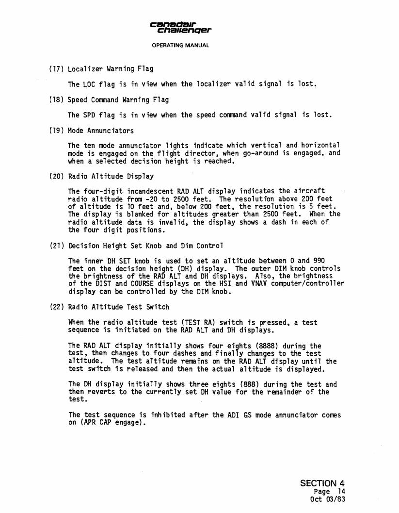
(17) Localizer Warning Flag
The LOC flag is in view when the localizer valid signal is lost.
(18) Speed Command Warning Flag
The SPD flag is in view when the speed command valid signal is lost.
(19) Mode Annunciators
The ten mode annunciator lights indicate which vertical and horizontal mode is engaged on the flight director, when go-around is engaged, and when a selected decision height is reached.
(20) Radio Altitude Display
The four-digit incandescent RAD ALT display indicates the aircraft radio altitude from -20 to 2500 feet. The resolution above 200 feet of altitude is 10 feet and, below 200 feet, the resolution is 5 feet. The display is blanked for altitudes greater than 2500 feet. When the radio altitude data is invalid, the display shows a dash in each of the four digit positions.
(21) Decision Height Set Knob and Dim Control
The inner DH SET knob is used to set an altitude between 0 and 990 feet on the decision height (DH) display. The outer DIM knob controls the brightness of the RAD ALT and DH displays. Also, the brightness of the DIST and COURSE displays on the HSI and VNAV computer/controller display can be controlled by the DIM knob.
(22) Radio Altitude Test Switch
When the radio altitude test (TEST RA) switch is pressed, a test sequence is initiated on the RAD ALT and DH displays.
The RAD ALT display initially shows four eights (8888) during the test, then changes to four dashes and finally changes to the test altitude. The test altitude remains on the RAD ALT display until the test switch is released and then the actual altitude is displayed.
The DH display initially shows three eights (888) during the test and then reverts to the currently set DH value for the remainder of the test.
The test sequence is inhibited after the ADI GS mode annunciator comes on (APR CAP engage).
SECTION 4 Page 14 Oct 03/83

chanenqer OPERATING MANUAL
(23) Decision Height Display
The three-digit incandescent DH display shows preselected decision height between 0 and 990 feet as set by the DH SET knob. When the aircraft is at or below the preselected decision height, the DH annunciator lights come on to alert the pilot.
B. Horizontal Situation Indicator (Figure 4)
The horizontal situation indicator combines numerous inputs to provide a map-like display of the aircraft position. The indicator displays aircraft displacement relative to VOR radials, localizer, and glideslope beam. Relative radio bearing is also displayed. The HSI is shown in Figure 4 (Sheet 1) and described in paragraphs (1) through (17).
For aircraft 1021 and subs, The HSI is shown in Figure 4 (Sheet 2) and described in paragraphs (1) through (22), except for paragraphs (12), (13) and (14) which are not applicable.
(1) Aircraft Symbol
A fixed miniature aircraft symbol corresponds to the longitudinal axis of the aircraft and lubber line markings. The symbol shows aircraft position and heading with respect to the rotating heading dial. The symbol also shows the aircraft position in relation to a radio course.
(2) Heading Dial
Displays gyro stabilized magnetic compass information on a dial which rotates with the aircraft throught 360 degrees. The azimuth ring is graduated in 5-degree increments. Fixed heading marks are at the fore and aft lubber lines.
(3) Heading Bug
The notched orange heading bug is positioned on the rotating heading dial by the remote heading knob to select and display preselected compass heading. The bug rotates with the heading dial to indicate that the difference between the bug and the forward lubber line index is the amount of error applied to the flight director computer.
(4) Heading Flag
The HDG flag is in view when the heading signal from the directional gyro becomes invalid, primary power to the ADI is lost, or the error between the displayed heading and the received heading signal exceeds 8 + 2 degrees.
SECTION 4 Page 15
Oct 03/83

canadair ctiaiientjer OPERATING MANUAL
DISTANCE DISPLAY
COURSE DISPLAY
VERTICAL MODE ANNUIMICIATOR
COURSE DEVIATION BAR
VERTICAL WARNING FLAG
COURSE .SELECT
POINTER
RNAV MODE ' ANNUNCIATOR
- TO FROM POINTER (NAV MODE ANNUNCIATOR)
. ALERT ANNUNCIATOR
-AFT LUBBER USE
BEARING POINTER ANNUNCIATOR
RECIPROCAL COURSE POINTER
BEARING SELECT PUSHBUTTONS
EFFECTIVITY: A/C 1004 TO 1020
Horizontal Situation Indicator Figure 4 (Sheet 1)
SECTION 4 Page 16
Oct 03/33
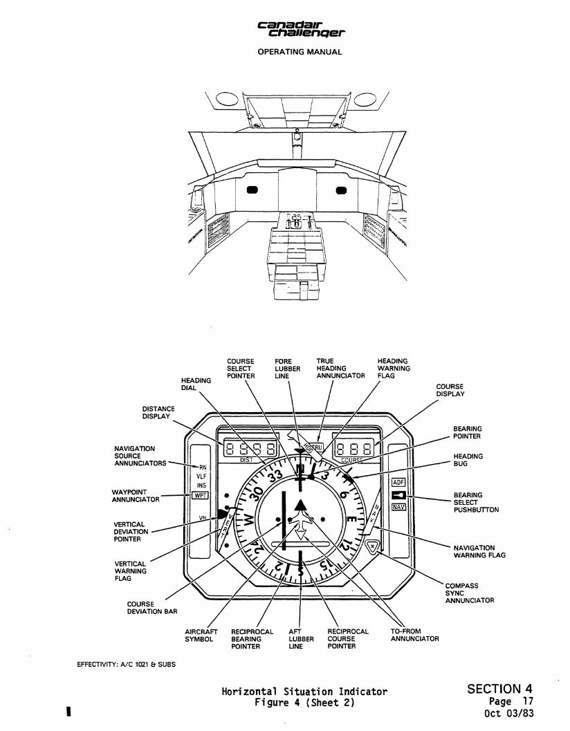
canadlair ctiaiiencjer OPERATING MANUAL
HEADING DIAL
COURSE FORE TRUE HEADING SELECT LUBBER HEADING WARNING POINTER LINE ANNUNCIATOR FLAG
DISTANCE DISPLAY
NAVIGATION SOURCE ANNUNCIATORS
WAYPOINT ANNUNCIATOR
VERTICAL DEVIATION POINTER
VERTICAL WARNING FLAG
COURSE DEVIATION
COURSE DISPLAY
BEARING POINTER
HEADING BUG
BEARING SELECT PUSHBUTTON
NAVIGATION WARNING FLAG
COMPASS SYNC ANNUNCIATOR
AIRCRAFT RECIPROCAL AFT RECIPROCAL TO-FROM SYMBOL BEARING LUBBER COURSE ANNUNCIATOR
POINTER LINE POINTER
EFFECTIVITY: A/C 1021 & SUBS
Horizontal Situation Indicator Figure 4 (Sheet 2)
SECTION 4 Page 17
Oct 03/83

chanenQer OPERATING MANUAL
(5) Course Select Pointer
The yellow course pointer is positioned on the rotating heading dial by the remote course knob to select a magnetic bearing that coincides with the desired VOR radial or localizer course. The course pointer rotates with the rotating heading dial to provide a continuous readout of course error to the flight director computer.
(6) Course Display
A digital readout in degrees of the course selected by the course knob.
(7) Course Deviation Bar
Represents the centreline of the selected VOR, RNAV, or localizer course. The aircraft symbol shows aircraft position in relation to the selected course.
(8) Course Deviation Dots
In VOR operation, each dot represents a 5-degree deviation from centreline. In ILS operation, each dot represents a deviation of 1 degree from centreline. In RNAV operation, the sensitivity of the deviation bar is a function of the type of RNAV computer used. Therefore, the distance represented by each dot is determined by the particular RNAV computer installed.
(9) Vertical Deviation Pointer
The vertical deviation pointer displays VNAV or GS deviation. The pointer is in view only when the VHF navigation receiver is tuned to a localizer frequency or VNAV mode is selected. Aircraft is below glide path if pointer is displaced upward. In the VNAV mode, the deviation display represents a vertical path error. The sensitivity of the display is a function of the type of VNAV computer installed.
(10) Vertical Warning Flag
The VERT flag is in view when the vertical deviation valid signal is lost.
(11) Distance Display
The distance display is a four-digit display which indicates slant range distance in nautical miles to the selected DME station. The display goes blank when the input is off or invalid, and all digits show dashes.
SECTION 4 Page 18
Oct 03/83

OPERATING MANUAL
(12) NAV Mode Annunciator
A four-position rotary disc which displays through the opening in the mask the following data:
- When white arrow is toward course pointer, aircraft is flying (to) selected VOR station
- When white arrow is toward tail of course pointer, aircraft is flying (from) the VOR station
- Red and yellow stripes appearing in both windows warn pilot that radio data are unusable
- Fourth position is blank indicating that NAV receiver is tuned to a valid localizer frequency.
(13) RNAV Mode Annunciator
A display in the upper right of the indicator face provides the following data:
- When the HSI is displaying RNAV data, the display reads RN
- When the HSI is displaying normal radio data, the display is blank
(14) Alert Annunciator
The display lights alert the pilot that the aircraft is approaching a selected waypoint.
(15) Vertical Mode Annunciator
Indicates whether vertical deviation information is from VNAV or glideslope.
(16) Bearing Pointer
This pointer indicates relative bearing to the selected radio station.
(17) Bearing Select Pushbuttons and Annunciators
Provide annunciated selection of ADF or NAV bearing information to be presented on the bearing pointer. On power-up, NAV is annunciated.
(18) True Heading Annunciator
If INS is available and is selected as a navigation source, the heading data to the HSI is INS true heading and is annuciated by the TRU annunciator. Without INS, the TRU annunciator is off and heading data is from the magnetic compass.
SECTION 4 Page 19
Oct 03/83
canadair ctiauencfer
OPERATING MANUAL
(19) Navigation Warning Flag
The NAV flag is in view when the navigation valid signal is lost.
(20) Compass Sync Annunciator
The compass sync annunciator consists of the symbol . or + (dot or cross) displayed in a window. When the compass system is in the slaved mode and synchronized, the display slowly oscillates between . and + to indicate that the rotating heading dial is synchronized with the gyro-stabilized magnetic heading.
(21) Navigation Source Annunciators
The RN,VLF, INS and VN annunciators indicate the source of navigation displayed by the HSI. The annunciators are all off for V0R/L0C and glideslope.
(22) To-From Annunciator
The to-from annunciator is displayed by a white arrow pointing toward the course select pointer when the aircraft is flying (to) a selected VOR station and a white arrow pointing toward the tail of the course select pointer when the aircraft is flying (from) the VOR station.
Instrument Remote Controller (Figure 5)
The pedestal mounted instrument remote controller is used to select the desired heading and course as displayed on pilot's and copilot's HSI.
Pilot's Altimeter (Figure 6)
The pilot's altimeter provides a servo-driven drum/pointer display of barometrically corrected pressure altitude. The barometric pressure is set manually with the BARO knob and displayed in units of inches of mercury and millibars on the baro counter. The altimeter provides the following displays:
- Counter drum display of altitude, marked in 20-foot increments
- Pointer display of altitude between thousand-foot levels with 20-foot graduations.
Altitudes below 10,000 feet are indicated by a black and white Crosshatch on the left digit position of the counter display.
SECTION 4 Page 20 Oct 03/83

canadair chauenejer
OPERATING MANUAL
COURSE 1 KNOB
Sets course pointer and course digital read-out on pilot's HSI to the desired course.
COURSE 2 KNOB
Sets course pointer and course digital read-out on copilot's HSI to the desired course.
HEADING KNOB
Sets heading bugs on pilot's and copilot's HSI to the desired heading.
Instrument Remote Controller Figure 5
SECTION 4 Page 21
Oct 03/83

canatiair chaiietiQer
OPERATING MANUAL
ALTITUDE POINTER
BAROMETRIC PRESSURE SET KNOB
ALTITUDE DISPLAY
BAROMETRIC PRESSURE
Altimeter Figure 6
SECTION 4 Page 22
Oct 03/83

OPERATING MANUAL
(1) Altitude Alert
The altitude alert annunciator light comes on to provide a visual indication when the aircraft is within 1000 feet of the preselected altitude during the capture manoeuvre and goes out when the aircraft is within 250 feet from the preselected altitude. After capture, the light comes on if the aircraft departs more than 250 feet from the selected altitude, and goes out when the aircraft has departed more than 1000 feet from the selected altitude. A momentary audio alert is also provided when the aircraft is within 1000 feet of the preselected altitude or has departed 250 feet from the selected altitude after capture.
(2) Failure Warning Flag
An internal failure monitor controls a failure warning flag which indicates power loss or data invalid.
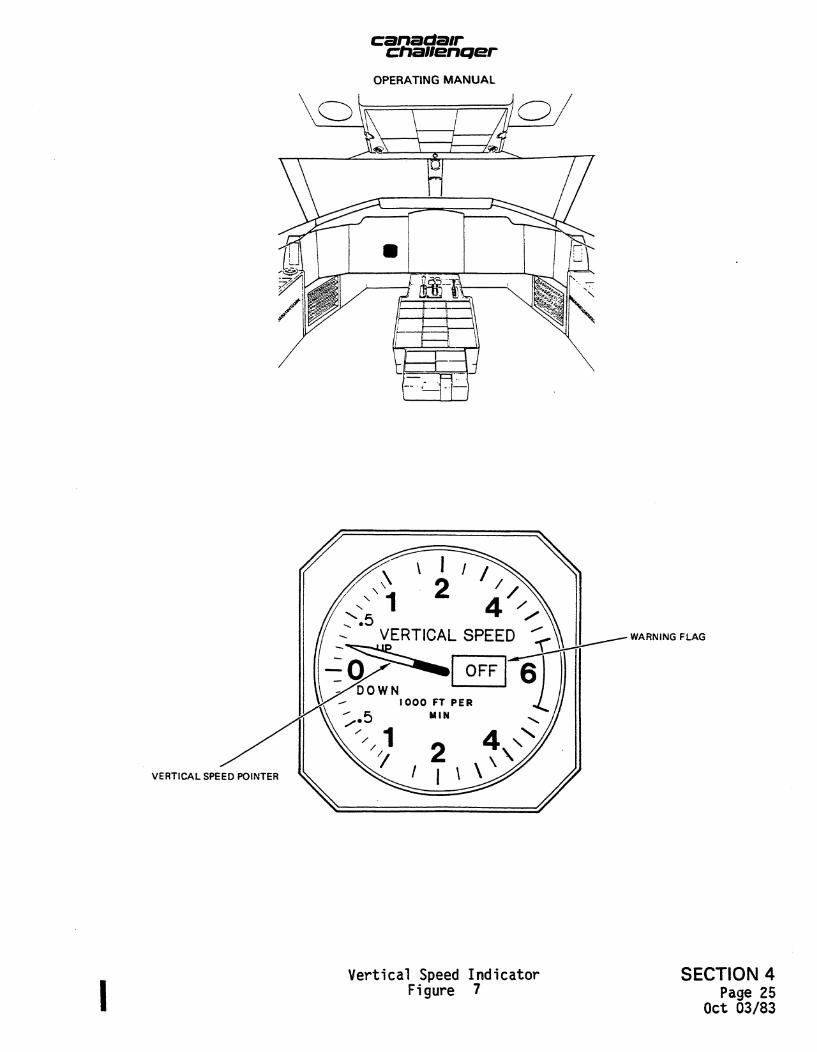
Pilot's Vertical Speed Indicator (Figure 7)
The pilot's vertical speed indicator provides a servo-driven pointer display of vertical speed. Vertical speed rates from 0 to +6000 feet per minute are displayed on the indicator.
Pilot's Mach/Airspeed Indicator (Figure 8)
The pilot's Mach/airspeed indicator is a totally servo-driven instrument with a counter display of Mach and pointer displays of airspeed and maximum operating airspeed (Vmo) as computed in the air data computer.
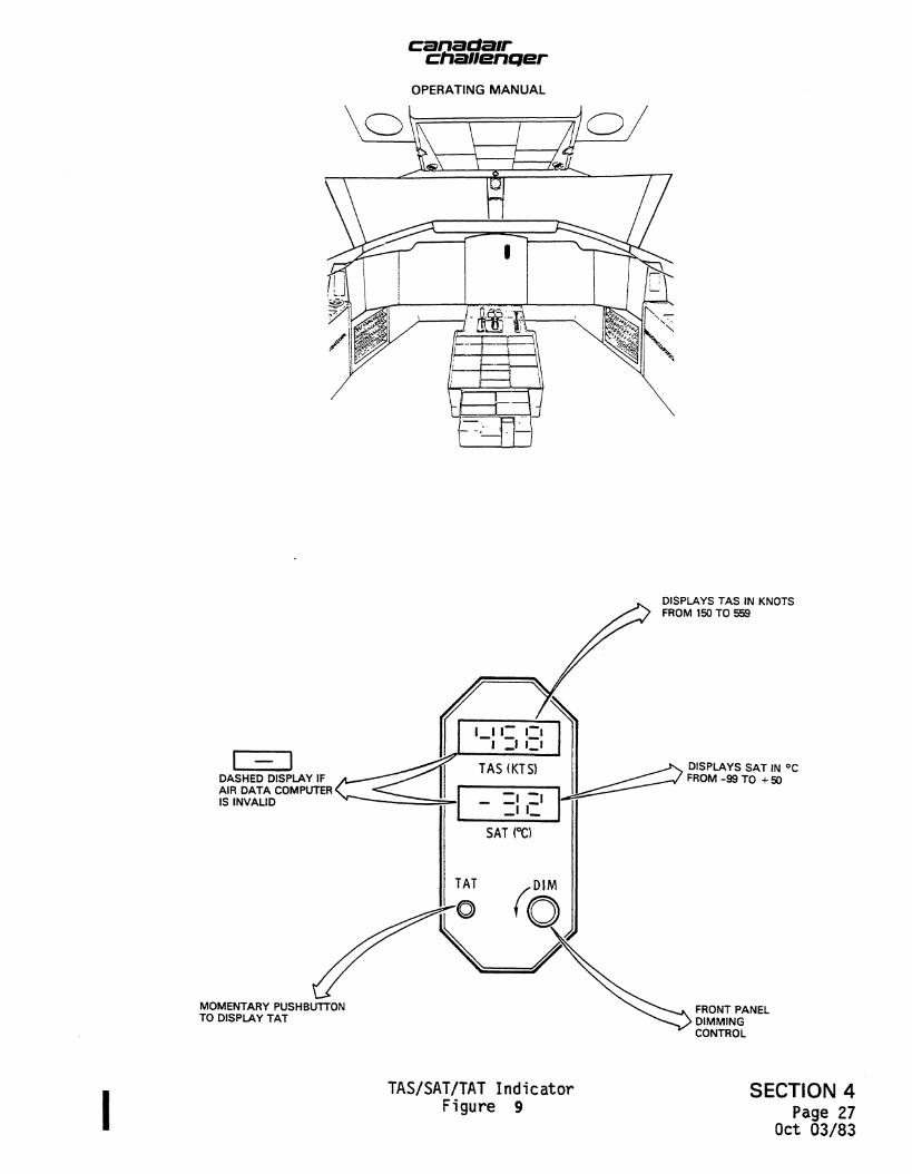
TAS/SAT/TAT Indicator (Figure 9)
The combined true airspeed, static air temperature/total air temperature indicator provides and incandescent digital display of both TAS and SAT or TAT signals as generated by the air data computer.
VNAV Computer/Controller (Figure 10)
The VNAV computer/controller (VNCC) provides data insertions and displays for altitude alerting, altitude preselect and VNAV modes. In operation, the pilot enters data by turning the display selector switch to the desired position and slewing with the set knob. The slew speed is proportional to the amount of rotation of the knob.
(1) Altitude Preselect
The altitude is selected by placing the selector switch to ALT and slewing to the desired value. No further action is taken on the VNCC. To initiate altitude preselect, the ALTSEL switch/light is selected on the flight director mode selector.
SECTION 4 Page 23
Oct 03/83

chanentjer OPERATING MANUAL
Altitude Alert
As the aircraft reaches a point 1,000 feet from the selected altitude, the light on the altimeter comes on and the warning horn sounds for 1 second. The light remains on until the aircraft is 250 feet from the selected altitude. If the aircraft now deviates by 250 feet from the selected altitude, the light comes on again and the horn sounds . The light remains on until the aircraft returns to within 250 feet of the selected altitude or a new altitude is set, which resets the alert horn and light.
Vertical Navigation Computation
The use the VNAV computation capability of the VNCC, the pilot must set the station elevation, bias distance and vertical angle after selecting the desired altitude. This is accomplished as follows:
(a) The station elevation, STAEL, position is selected and the station elevation is set on the display by rotating the set knob. Resolution is 100 feet.
(b) The TO or FR position is selected and the distance ahead of or beyond the NAVAID (alongtrack offset) is set. Resolution is 0.1 nautical mile.
(c) The vertical angle, VANG, position is selected and the computed vertical path angle to the desired destination is displayed. The pilot may observe the continuously computed flight path angle (angle compute mode) until the desired angle is displayed, and then press the VNAV switch/light on the flight director mode selector. This action freezes the selected angle and captures the vertical path.
(d) The set knob may be used to preset a desired vertical angle (fixed angle mode). Pressing the VNAV switch/light arms the system to capture the selected vertical path angle. The VNCC supplies a vertical deviation signal similar to GS deviation. The vertical deviation signal is displayed on the pilotfs HSI vertical deviation pointer when the VNAV mode is annunciated on the pilots HSI. If the VNAV switch/light is not pressed before the selected angle is reached, the VNCC reverts to angle compute mode, continuously displaying the computed angle to the desired destination. The selected angle is limited to HK9.9 degrees of flight path.
SECTION 4 Page 24
Oct 03/83
canatiair chatientjer
OPERATING MANUAL
VERTICAL SPEED POINTER
WARNING FLAG
Vertical Speed Indicator Figure 7
SECTION 4 Page 25
Oct 03/83

canactair ctianenqer
OPERATING MANUAL
MACH NUMBER
M 0 POINTER DESIRED AIRSPEED REFERENCE BUGS
WARNING FLAG
AIRSPEED POINTER
Mach/Airspeed Indicator Figure 8
SECTION 4 Page 26
Oct 03/83
canadair chaiienQer
OPERATING MANUAL
O k \ i /HO
DASHED DISPLAY IF AIR DATA COMPUTER IS INVALID
MOMENTARY PUSHBUTTON TO DISPLAY TAT
DISPLAYS TAS IN KNOTS FROM 150 TO 559
DISPLAYS SAT IN °C FROM-99 TO +50
FRONT PANEL DIMMING CONTROL
TAS/SAT/TAT Indicator Figure 9
SECTION 4 Page 27
Oct 03/83

ctiauenqer OPERATING MANUAL
STAEL
To set station elevation, the selector switch is set to STAEL and the SET knob is slewed to the desired elevation. Resolution is 100 feet.
ALT
To set altitude, the selector 9**tc* a tet to ALT and the SET knob is slewed to the desired attitude. The altitude preselect mode is men mtutted by pressing the ALTSEL switch/light on the tfcgm abactor mode selector.
T O - F R
To set distance, the selector switch is set to TO or FR and the SET knob is slewed to the distance to or from the navigation aid (alongside track). Resolution is 0.1 nautical mile.
SET KNOB
VANG
When the selector switch is set to VANG, me computed vertical path angle is displayed.
VNAV Computer/Controller SECTION 4 Figure 10 P a g e 2 8
Oct 03/83

canadair chaiiencjer
OPERATING MANUAL
(4) Vertical Path Flying
When a vertical path is selected by pressing the VNAV swith/light, the vertical deviation, with respect to the selected vertical path, is displayed on the pilot's HSI. Pressing the VNAV switch/light causes the aircraft to capture the vertical path immediately if in the angle compute mode, or when the preset angle is reached in the fixed angle mode. At the transition, the aircraft is guided smoothly along the selected vertical path until a position approaching the selected altitude is reached. A second transition to the selected altitude is then made to level off. As the aircraft reaches the selected altitude, the altitude hold mode is automatically initiated and the VNAV mode is reset.
(5) Vertical Input Cancelling
As the aircraft passes the selected point or desired altitude, the vertical path problem is cancelled by replacing VANG, TO, FR and STAEL by dashes. This prevents use of erroneous VORTAC data for a subsequent VNAV problem.
If the computed angle reaches a preset maximum, the provision for vertical path navigation is cancelled in the same manner. This cancellation is preceded by flashing of the display for the last degree of computed vertical path angle.
I. Instrument Comparator (Figure 11)
The instrument comparator is a self contained five-channel, six-light instrumentation comparator monitor. It compares the dual installation for correct pitch and roll attitude, heading, localizer signal and glideslope signal. If a pre-determined difference exists between the two systems, the fault is indicated on the annunciator lights; ROLL, PITCH, HDG, GS and LOC. The instrument comparator has a self-monitoring feature which checks the internal electronics of the comparator and indicates an internal failure on the MNTR light.
Two lighted switches provide a test of the system. The TEST/RESET switch initiates checks of the internal electronics and annunciator lights. The switch also resets any previously disabled channel. The WARN/DISABLE switch allows the pilot to disable any annunciator light that is on. If the fault corrects itself, the light resets automatically.
9. SYSTEM CONTROLS
A. Flight Director Mode Selector (Figure 12)
The flight director mode selector provides all mode selection (except go-around and touch control steering) for the flight director. Mode annunciation is provided on both the mode selector and AOI.
SECTION 4 Page 29
Oct 03/83

canadair chauencjer
OPERATING MANUAL
Heading Select Mode
The heading select mode is selected by pressing the HD6 switch/light on the flight director mode selector. The HDG annunciator on the ADI comes on. In the HDG mode, the flight director computer provides inputs to the roll steering pointer to corranand a turn to the heading indicated by the heading bug on the HSI. The heading select signal is gain programmed as a function of airspeed. When the HDG mode is selected it overrides the NAV, BC and APR modes. If there is a loss of valid data from the vertical gyro or compass, the ADI command cue goes out of view.
Navigation Mode
The navigation mode, NAV, represents a family of modes for various systems including VOR, localizer and RNAV.
VOR Mode
The VOR mode is selected by pressing the NAV switch/light on the flight director mode selector with the VHF navigation receiver tuned to a VOR frequency. When outside the lateral bracket sensor trip point, the ADI command cue receives a heading select command as described above and the HDG mode annunciators on the mode selector and ADI come on along with the NAV ARM annunciator on the mode selector. Upon reaching the lateral bracket sensor trip point, the system automatically switches to the VOR mode. The HDG and NAV ARM annunciators go off and the NAV CAP annunciator on the mode selector and NAV annunciator on the ADI come on.
At capture, a command is generated to capture and track the VOR beam. VOR deviation is gain programmed as a function of distance from the station. This programming corrects for beam convergence thus optimizing the gain through the useful VOR range. The DME must be tuned to the same VOR station as the selected VHF navigation receiver. The course error signal is gain programmed as a function of airspeed. Crosswind washout is included, which maintains the aircraft on beam centre in the presence of crosswind.
The intercept angle and DME the range signal are used in determining the lateral bracket sensor trip point to ensure smooth and comfortable performance during bracketing.
When passing over the station, an overstation sensor detects station passage, removing the VOR deviation signal from the command until it is no longer erratic. While over the station, course changes are made by selecting a new course on the HSI.
SECTION 4 Page 30
Oct 03/83

canadair chaiienper
OPERATING MANUAL
PITCH LIGHT
Comes on when a difference exists between the dual pitch channels.
ROLL LIGHT
Comes on when a difference exists between the dual roll channels.
LOC LIGHT
Comes on when a difference exists between the two localizer signals.
TEST RESET SWITCH/LIGHT
Tests the internal electronics and an-nuniciator lights.
Resets any prior disabled channel. GS LIGHT
Comes on when a difference exists between the two glide slope signals.
HDG LIGHT
Comes on when a difference exists between the two heading signals.
Comes on when the internal power supply voltage drops below a predetermined level.
WARN DISABLE SWITCH/LIGHT
Amber light comes on when one or more drive signals from the above six functions produce a master warning drive signal. Pressing the button disables all monitoring functions except the voltage monitor.
Instrument Comparator Figure 11
SECTION 4 Page 31
Oct 03/83

canadair chanenQer
OPERATING MANUAL
NAVIGATION MODE
HEADING SELECT-MODE
BACK COURSE MODE
LOCALIZER APPROACH
MODE
JHDG |NAV APR BC| VORAPB^BY
VOR APPROACH MODE
ON iARM CAP ARM CAP
ALTITUDE HOLD MODE
ARM CAP
) vs ON
ARM CAP
IAS
ON
SBY |1 J
MACHC
ON
D>
VERTICAL SPEED HOLD MODE
INDICATED AIRSPEED HOLD MODE
VERTICAL NAVIGATION
MODE
MACH HOLD MODE
Flight Director Mode Selector Figure 12
SECTION 4 Page 32
Oct 03/83

canadair chauenQer
OPERATING MANUAL
If the VHF navigation receiver is not valid prior to the capture point, the lateral beam sensor does not trip and the system remains in the HD6 mode. After capture, if the VHF navigation receiver, compass data, or vertical gyro go invalid, the ADI command cue biases out of view. The NAV CAP annunciator on the mode selector and NAV annunciator on the ADI go out if the VHF navigation receiver becomes invalid.
VOR Approach Mode
The VOR approach mode is selected by pressing the VOR APR switch/light on the flight director mode selector with the VHF navigation receiver tuned to a VOR frequency. The mode operates identically to the VOR mode with gains optimized for VOR approach. The NAV and APR annunciators on the ADI come on.
RNAV Mode
The RNAV mode is selected by pressing the NAV switch/light when the RNAV deviation is supplied to the system. The RNAV approach mode is selected by pressing the VOR APR switch/light as for the VOR approach mode. Operation is similar to the VOR and VOR approach modes with separate gains provided to optimize for the RNAV input. RN annunciation on the HSI identifies the RNAV mode. Flight director mode selector and ADI annunciations are the same as in the VOR modes.
Localizer Mode
The localizer mode is selected by pressing the NAV switch/light on the flight director mode selector with the VHF navigation receiver tuned to a LOC frequency. Mode selection and annunciation in the LOC mode are the same as in the VOR mode except LOC is annunciated on the ADI. The localizer deviation signal is gain programmed as a function of radio altitude, time and airspeed. If the radio altimeter is invalid, gain programming is a function of glideslope capture, time and airspeed. Other valid logic is the same as the VOR mode.
Back Course Mode
The back course mode is selected by pressing the BC switch/light on the flight director mode selector. Back course operates the same as the LOC mode with the deviation and course signals reversed to make a back course approach on the localizer. Glideslope capture is locked out when in the BC mode. When BC is selected and outside the lateral beam sensor trip point, BC ARM and HDG are annunciated on the mode selector along with HDG on the ADI. At the capture point, BC CAP is annunciated, BC ARM and HDG go out and BC is annunciated on the ADI.
SECTION 4 Page 33 Oct 03/83

canaaair ctiaiienQer
OPERATING MANUAL
(8) Localizer Approach Mode
The localizer approach mode is used to make an ILS approach. Pressing the APR switch/light on the flight director mode selector with a LOC frequency tuned on the VHF navigation receiver arms both the localizer and glideslope modes. No alternate NAV source can be selected and the receiver must be tuned to an ILS frequency. When the APR switch/light is pressed and the above conditions are met, the NAV and APR modes are armed to capture the localizer and glideslope respectively. Operating the LOC mode is the same as described above. With the APR mode armed, the pitch axis can be in any one of the other pitch modes except go-around. When reaching the vertical beam sensor trip point, the system automatically switches to the glideslope mode. The pitch mode and APR ARM annunciators go off and the APR CAP annunciator comes on along with GS on the ADI. At capture, a command is generated to approach the glideslope beam. Capture can be made from above or below the beam. The glideslope deviation is gain programmed as a function of radio altitude, time and airspeed. The vertical speed signal is used on the approach to improve glideslope tracking. The APR CAP annunciator on the mode selector and GS annunciator on the ADI go out if the GS receiver becomes invalid after capture. Glideslope capture is interlocked so that the localizer must be captured prior to glideslope capture. If the glideslope receiver is not valid prior to capture, the vertical beam sensor does not trip and the system remains in the pitch mode. After capture, if the glideslope receiver or vertical gyro become invalid, the ADI command cue goes out of view.
(9) Pitch Hold Mode
Whenever a roll mode is selected without a pitch mode, ADI command cue displays a pitch attitude hold command. The pitch attitude can be changed by pressing the touch control steering (TCS) button on the control wheel (refer to Figure 13) and manoeuvring the aircraft. The ADI command cue is synchronized to fly-straight while the button is pressed. Upon release of the button, the pitch command is such as to maintain the new pitch attitude. In the pitch hold mode, the ADI command cue goes out of view if the vertical gyro is not valid.
(10) Altitude Hold Mode
The altitude hold mode is selected by pressing the ALT switch/light on the flight director mode selector. When the ALT mode is selected, it overrides the APR CAP, GA, IAS, VS, MACH, ALTSEL CAP or PITCH HOLD modes. ALT is annunciated on the ADI. In the ALT mode, the pitch command is proportional to the altitude error provided by the air data computer. The altitude error signal is gain programmed as a function of airspeed. Pressing and holding the TCS button allows the pilot to manoeuvre the aircraft to a new altitude hold reference without disengaging the mode. Once engaged in the altitude hold mode, the
SECTION 4 Page 34
Oct 03/83
canatiiair chaiienQer
OPERATING MANUAL
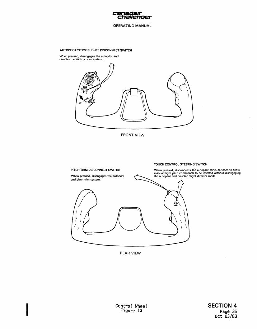
AUTOPILOT/STICK PUSHER DISCONNECT SWITCH
When pressed, disengages the autopilot and disables the stick pusher system.
FRONT VIEW
PITCH TRIM DISCONNECT SWITCH
When pressed, disengages the autopilot and pitch trim system.
TOUCH CONTROL STEERING SWITCH
When pressed, disconnects the autopilot servo clutches to allow manual flight path commands to be inserted without disengaging the autopilot and coupled flight director mode.
REAR VIEW
Control Wheel SECTION 4 figure 13 page 35
Oct 03/83

canatiair chaiienc/er
OPERATING MANUAL
mode resets if the air data computer is not valid and the ADI command cue goes out of view if the vertical gyro is not valid. If the baro setting on the altimeter is changed, a command is generated to fly the aircraft back to the original altitude reference.
(11) Indicated Airspeed Hold Mode
The indicated airspeed hold mode is selected by pressing the IAS switch/light on the flight director mode selector. When IAS is selected, it overrides the APR CAP, GA, ALT, VS, MACH, ALTSEL CAP or PITCH HOLD modes. VRT is annunciated on the ADI. In the IAS mode, the pitch command is proportional to airspeed error provided by the air data computer. Pressing and holding the TCS button allows the pilot to manoeuvre the aircraft to a new airspeed hold reference without disengaging the mode. Once engaged in the IAS mode, the mode resets if the air data computer is not valid and the ADI command cue goes out of view if the vertical gyro is not valid.
(12) Vertical Speed Hold Mode
The vertical speed hold mode is selected by pressing the VS switch/light on the flight director mode selector. When VS is selected, it overrides the APR CAP, GA, ALT, ALTSEL CAP, IAS, MACH or PITCH HOLD modes. VRT is annunciated on the ADI. Pressing and holding the TCS button allows the pilot to manoeuvre the aircraft to a new vertical speed hold reference without disengaging the mode. Once engaged in the VS mode, the mode resets if the air data computer is not valid and the ADI command cue goes out of view if the vertical gyro is not valid.
(13) Mach Hold Mode
The Mach hold mode is selected by pressing the MACH switch/light on the flight director mode selector. When the Mach hold mode is selected, it overrides the APR CAP, GA, ALTSEL CAP or PITCH SYNC modes. VRT is annunciated on the ADI. In the Mach hold mode, the pitch command is proportional to the Mach provided by the air data computer. Pressing and holding the TCS button allows the pilot to manoeuvre the aircraft to a new Mach hold reference without disengaging the mode. Once engaged in the Mach hold mode, the mode resets if the air data computer is not valid and the ADI command cue goes out of view if the vertical gyro is not valid.
(14) Standby Mode
The standby mode is selected by pressing the SBY switch/light on the flight director mode selector. This resets all other flight director modes and biases the ADI command cue from view. While pressed, the SBY switch/light acts as a lamp test. All mode annunciators come on and the flight director warning flag (FD) comes into view. When the switch/light is released, all mode annunciators go out and the FD warning flag retracts from view.
SECTION 4 Page 36
Oct 03/83

canadair chauencjer
OPERATING MANUAL
(15) Altitude Preselect Mode
The altitude preselect mode is selected by pressing the ALTSEL switch/light on the flight director mode selector. The desired altitude is selected on the VNAV computer/controller and VS, IAS or MACH is selected as the mode to fly to the selected altitude.
When outside the altitude bracket trip point, the ALTSEL ARM annunciator and the selected pitch mode annunciator on the mode selector come on. When reaching the altitude bracket trip point, the system switches automatically to the ALTSEL CAP mode and the previous pitch mode is cancelled. At bracket, a command is generated to capture the selected altitude. When the selected altitude is reached, the ALTSEL CAP mode is automatically cancelled and the system switches to the ALT hold mode. If the air data computer is not valid, the altitude preselect mode cannot be selected.
(16) VNAV Mode
After the VNAV mode data (preselected altitude, distance and vertical angle) is set in the VNAV computer/controller (refer to paragraph H, VNAV Computer/Controller), the VNAV mode is selected by pressing the VNAV switch/light on the flight director mode selector. If a preset angle was established, the system arms with VNAV ARM annunciated. Upon reaching the selected vertical angle, the system automatically switches to VNAV capture. The ADI command cue indicates a fly-to condition to smoothly capture and track the vertical path to the preselected altitude. Just prior to reaching the preselected altitude, the system reverts to the ALT hold mode.
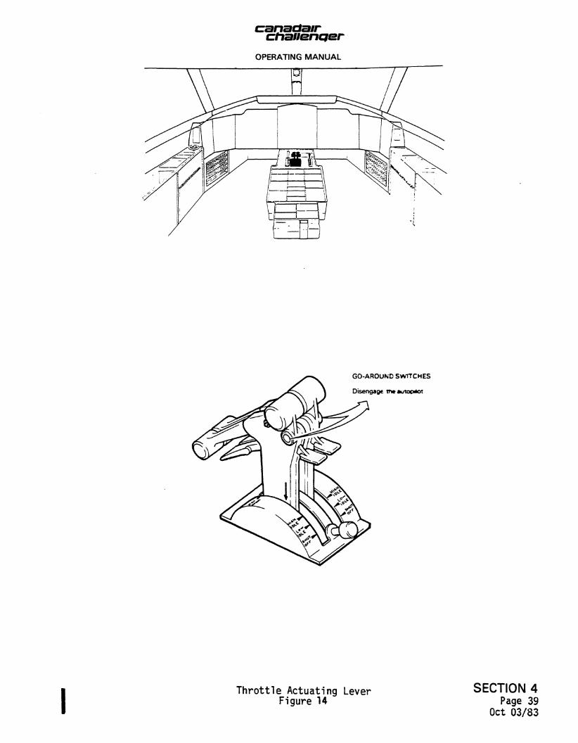
(17) Go-Around Mode (Figure 14)
The go-around mode is selected by pressing the remote go-around switch on the throttle actuating lever. When the mode is selected, all other modes are reset and the go-around (GA) annunciator on the ADI comes on. The ADI command cue receives the go-around command which is a fixed pitch up attitude command. Once go-around i s selected, any roll mode can be selected cancelling the wings level command. The go-around mode is cancelled by selecting another pitch mode or touch control steering.
(18) Touch Control Steering
The touch control steering (TCS) is selected on the control wheel. With the autopilot engaged and lateral or vertical mode selected on the flight director mode selector, operation of the TCS button allows manual manoeuvering of the aircraft in roll or pitch. When the TCS button is released, the existing roll and pitch attitudes are maintained.
SECTION 4 Page 37 Oct 03/83
chanentjer OPERATING MANUAL
Use of TCS during glideslope control or during ALTSEL CAP permits manoeuvering while the TCS button is pressed. However, when TCS button is released, normal glideslope control or ALTSEL control is resumed.
If the TCS button is released at bank angles of less than 6 degrees, the aircraft returns to wings level.
B. Autopilot Controller (Figure 15)
The autopilot and flight director are fully integrated in operation and mode selection. Autopilot operation is controlled by the autopilot controller.
(1) Yaw Damper Engage
The YD ENGAGE switch/light engages the yaw damper. The yaw damper provides dutch roll damping and turn coordination throughout the flight regime. It engages automatically when the autopilot is engaged.
(2) Autopilot Engage
The autopilot may be engaged in any reasonable attitude by pressing the AP ENGAGE switch/light. If there are no modes selected on the flight director mode selector, pitch attitude is maintained and the aircraft is rolled to wings level, at which time the aircraft heading is held.
If any flight director lateral mode or vertical path mode is selected prior to autopilot engagement, the autopilot is automatically coupled to the selected flight director mode. Selection of a lateral mode or a vertical path mode after the autopilot is engaged also automatically couples the autopilot to the selected mode.
(3) Turn Knob
Operation of the turn knob provides bank commands to the autopilot proportional to turn knob displacement. When the turn knob is operated, the lateral mode selected on the flight director mode selector is automatically cancelled. When the turn knob is returned to the detent position, a lateral mode can be reselected. The autopilot cannot be engaged if the turn knob is out of detent.
(4) Pitch Hold
When the autopilot is engaged and a vertical path mode is not selected, the aircraft pitch attitude is maintained. Movement of the pitch wheel on the autopilot (AP) controller changes the pitch attitude. If a vertical path mode is selected, the pitch hold is automatically cancelled. Movement of the pitch wheel when the autopilot is in a vertical path mode automatically cancels the vertical path mode. Movement of the pitch wheel with the autopilot coupled to the glideslope has no effect.
SECTION 4 Page 38 Oct 03/83
canaclair chauenqer
OPERATING MANUAL
GO-AROUND SWITCHES
Disengage tr» autoc*ot
Throttle Actuating Lever Figure 14
SECTION 4 Page 39
Oct 03/83

canatiair chaiienQor
OPERATING MANUAL
COUPLE SWITCH/LIGHT
When pressed, selects which flight director is controlling the autopilot.
The split legend, I and 2, sequences each time the switch/light is pressed.
PITCH WHEEL
Moving the PITCH wheel changes the reference pitch attitude in proportion to the movement of the wheel. When the autopilot is coupled to the glideslope, moving the PITCH wheel has no effect.
TURN KNOB
Provides bank commands to the autopilot proportional to knob displacement. When rotated out of detent, the lateral mode selected on the flight director is cancelled automatically. When returned to the detent position, a lateral mode can be reselected. The autopilot can not be engaged if the TURN knob is out of detent.
SOFT RIDE SWITCH/LIGHT
When pressed, lowers autopilot system gains for operation in turbulence and green ON light comes on.
fW5SCENDNcO^\RlDE
AP ENGAGE SWITCH/LIGHT
When pressed, the autopilot is engaged and green AP ENGAGE light comes on.
YD ENGAGE SWITCH/LIGHT
When pressed, the yaw clamper is engaged and green YD ENGAGE light comes on. The yaw damper engages automatically when the autopilot is engaged.
Autopilot Controller Figure 15
SECTION 4 Page 40
Oct 03/83

chauencier OPERATING MANUAL
(5) Couple
Either the pilot"s or copilot's f l ight director computers can couple to the autopilot, providing path control and mode selection from either side of the f l ight compartment. The COUPLE switch/light on the AP controller selects and indicates which f l ight director is driving the autopilot. The COUPLE switch/light has a split legend (1 or 2) which sequences with each actuation of the switch/light, when the autopilot is disengaged or a TCS button is pressed.
(6) Soft Ride
Soft ride is selected on the AP controller. Soft ride provides lowered autopilot system gains for operation in turbulence.
10. FAILURE MONITORING AND STATUS ANNUNCIATION
When a failure occurs in either of the dual servo axes (pitch and roll), and the monitor localizes the failure to a specific channel, a brake is applied to the affected axis. This results in automatic reversion to single channel operation in that axis only and annunciation on the autopilot status panel. The other axis continues to operate in the fail/passive dual channel configuration. Since the failed channel is no longer fail/passive, a torque limiter is activated for hardover protection.
A. Failure Warnings (Figure 16)
Failure annunciations (aural and/or visual) are presented immediately to alert the pilot that a failure has occurred.
(1) A flashing red A/P FAIL light (located on the instrument panel) comes on when the monitor detects a failed mode which requires the pilot to disconnect the autopilot.
The light goes out when the autopilot is disengaged. The warning occurs when either of the following conditions exists:
- A failure is detected but no brake is applied
- A failure is detected, the appropriate brake is applied, but the single-channel torque limiter fails to engage
(2) An amber A/P FAIL light comes on when the monitor detects a failure condition which is isolated to a channel. The amber light may be reset by momentarily pressing the light. Disengagement of the autopilot is not required since the failed channel is automatically disabled.
SECTION 4 Page 41 Oct 03/83

canadam chauentjer
OPERATING MANUAL
A/P FAIL SWITCH/LIGHT
Amber A/P FAIL light comes on when a failure is detected which does not require the autopilot to be disconnected. The light is reset by pressing the switch/light.
AFCS LIGHT
Red AFCS light:
Comes on for one second to wx*c*te • pttot selected autopilot disengagement.
Flashes for a non-localized yaw dampe* t»#ur» o* marfunction.
Is continuously on for an automatic *utop«*oT doconnect (not pilot selected).
A/P FAIL
A/P FAIL
A/P FAIL LIGHT
Red A/P FAIL light flashes when a failure is detected which requires the autopilot to be disconnected. The light goes out when the autopilot is disconnected.
Warning and Disengage Lights Figure 16
SECTION 4 Page 42
Oct 03/83

canatiair chauenQer
OPERATING MANUAL
(3) To facilitate rapid assessment of the situation, additional annunciations are presented on the autopilot status panel (refer to Figure 17). There are four autopilot status switch/lights located on the autopilot status panel. The switch/lights are identified as follows:
- ROLL 1 OFF
- ROLL 2 OFF
- PITCH 1 OFF
- PITCH 2 OFF
When one of the pitch or roll channels fails and the failed channel is braked and the other channel is torque-limited, the appropriate switch/light comes on (amber) to indicate which channel is disabled. The pilot is immediately warned of this condition by an amber A/P FAIL light.
When a failure cannot be isolated to a specific channel, the annunciators indicate the axis that has failed by flashing both amber lights for that axis and the red segment of the A/P FAIL light.
During normal (no failure) conditions the four switch/lights remain off. The switch/lights allow the pilot to manually select which channel is operating in the single channel configuration by pushing the appropriate switch/light when the autopilot is disengaged, then re-engaging the autopilot.
B. Autopilot Self-Test
Prior to each flight, the pilot tests for proper operation of the autopilot monitors, brakes and torque limiters by selection of a self-test mode switch/light located on the autopilot status panel (refer to Figure 17). Engaging the autopilot begins the test sequence.
SECTION 4 Page 43
Oct 03/83

canaaair chanencjer
OPERATING MANUAL
PITCH I SWITCH/LIGHT
Amber OFF light comes on to indicate a malfunction and disengagement of PITCH I channel.
Pressing PITCH I switch/light when the autopilot is disengaged reverts the system to single channel PITCH 2 operation.
YAW I SWITCH/LIGHT
Amber OFF light comes on to indicate a malfunction and disengagement of YAW I channel.
Pressing YAW I switch/light when the yaw damper is disengaged reverts the system to single channel YAW 2 operation.
ROLL 1 SWITCH/LIGHT
Amber OFF light comes on to indicate a malfunction and disengagement of ROLL I channel.
Pressing ROLL I switch/light when the autopilot is disengaged reverts the system to f""^ single channel ROLL 2 operation.
ROLL 2 SWITCH/LIGHT
Amber OFF light comes on to indicate a malfunction and disengagement of ROLL 2 channel.
Pressing ROLL 2 switch/light when the autop i lo t is disengaged reverts the system to single channel ROLL I operation.
PITCH 2 SWITCH/LIGHT
Amber OFF light comes on to indicate a malfunction and disengagement of PITCH 2 channel.
Pressing PITCH 2 switch/light when the autopilot is disengaged reverts the system to single channel PITCH I operation.
TEST 1 SWITCH
ROLL 1 OFF, PITCH 1 OFF and YAW 1 OFF lights come on when TEST 1 switch is pressed, indicating that the monitor brakes have been applied and that torque limiting is present in channel 1.
Pressing YAW 2 switch/light when the yaw damper is disengaged reverts the system to single channel YAW I operation.
TRIM UP AND DN ANNUNCIATOR LIGHTS
Amber UP light comes on if a nose-up out of trim condition exists.
Amber DN light comes on if a nose-down out of trim condition exists.
TEST 2 SWITCH
ROLL 2 OFFr PITCH 2 OFF and YAW 2 OFF lights come on when TEST 2 switch is pressed, indicating that the monitor brakes have been applied and that torque limiting is present in channel 2.
Autopilot Status Panel SECTION 4 Figure 17 Page 44
Oct 03/83