Operating Manual for VTC-200B, VTC-200C & VTC-300C (Mazatrol … VTC-200-300 Operating... ·...
530
Operating Manual for VTC-200B, VTC-200C & VTC-300C (Mazatrol Fusion 640M) Publication # C557SG0012E 7/99 CAUTION This Manual is published to assist experienced personnel on the operation, maintenance and/or programming of Mazak machine tools. All Mazak machine tools are engineered with a number of safety devices to protect personnel and equipment from injury or damage. Operators should not, however, rely solely upon these safety devices, but should operate the machine only after fully understanding what special precautions to take by reading the following documentation thoroughly. Do not attempt to operate or perform maintenance / repair on the machine without a thorough understanding of the actions about to be taken. If any question exists, contact the nearest Mazak service center for assistance. Certain covers, doors or safety guards may be open or removed to more clearly show machine components. These items must be in place before operating the machine. Failure to comply with this instruction may result in serious personal injury or damage to the machine tool. This manual was considered complete and accurate at the time of publication, however, due to our desire to constantly improve the quality and specification of all Mazak products, it is subject to change or modification.
Transcript of Operating Manual for VTC-200B, VTC-200C & VTC-300C (Mazatrol … VTC-200-300 Operating... ·...
Operating Manualfor
VTC-200B, VTC-200C & VTC-300C(Mazatrol Fusion 640M)
Publication # C557SG0012E
7/99
CAUTION
This Manual is published to assist experienced personnel on the operation, maintenanceand/or programming of Mazak machine tools.
All Mazak machine tools are engineered with a number of safety devices to protectpersonnel and equipment from injury or damage. Operators should not, however, relysolely upon these safety devices, but should operate the machine only after fullyunderstanding what special precautions to take by reading the following documentationthoroughly.
Do not attempt to operate or perform maintenance / repair on the machine without athorough understanding of the actions about to be taken. If any question exists, contactthe nearest Mazak service center for assistance.
Certain covers, doors or safety guards may be open or removed to more clearly showmachine components. These items must be in place before operating the machine.Failure to comply with this instruction may result in serious personal injury or damage tothe machine tool.
This manual was considered complete and accurate at the time of publication, however,due to our desire to constantly improve the quality and specification of all Mazakproducts, it is subject to change or modification.

Notes:
VTC-200B,200C & 300C Operation....................................................
SAFETY PRECAUTIONS S-1....................................................................
LOCKOUT PROCEDURE S-4.................................................................................
INSTALLATION PRECAUTIONS S-5......................................................................
WARNINGS S-8.......................................................................................................
Sec. 1: Introduction ...........................................................................
1 INTRODUCTION 1-1............................................................................................
1-1 List of Related Manuals and Documents 1-1.......................................................................
1-2 Pagination 1-1.....................................................................................................................
1-3 Numbering of Figures and Tables 1-2.................................................................................
2 SAFETY PRECAUTIONS 2-1..............................................................................
2-1 Rule 2-1...............................................................................................................................
2-2 Basic Safety Items 2-1.........................................................................................................
2-3 Clothing and Personal Safety 2-3........................................................................................
2-4 Operational Safety 2-3.........................................................................................................
2-5 Safety Considerations Relating to Holding Workpieces and Tooling 2-4............................
2-6 Maintenance Safety 2-5.......................................................................................................
2-7 Workplace Safety 2-6..........................................................................................................
2-8 Safety Considerations Relating to Chip Conveyor 2-6........................................................
2-9 Safety Equipment 2-7..........................................................................................................
2-10 Remarks on the Cutting Conditions Recommended by the NC 2-8..................................
2-11 Safety Nameplates 2-8......................................................................................................
Sec. 2: Machine Operation ...............................................................
1 OUTLINE OF THE MACHINE 1-1........................................................................
1-1 Axis Definitions 1-1..............................................................................................................
1-2 Names and Locations of Machine Units 1-2........................................................................
2 OPERATION PANELS 2-1...................................................................................
2-1 Locations of Operation Panels 2-1......................................................................................
2-2 NC Operation Panel 2-2......................................................................................................2-2-1 Arrangement of Switches on the NC Operation Panel 2-3........................................
2-2-2 Names and Functions of Switches and Other Controls on the NC Operation 2-4.....
2-3 Auxiliary Operation Panel 2-9..............................................................................................
2-4 Data Input/Output Panel 2-10................................................................................................
2-5 Magazine Operation Panel 2-11............................................................................................
2-6 Main Power Disconnect Switch 2-12.....................................................................................
2-7 Operator�s Door Interlock 2-13..............................................................................................2-7-1 MACHINE SET UP Switch (Key-lock Type Switch) 2-13.............................................
3 MANUAL OPERATION 3-1..................................................................................
3-1 Inspection before Starting Operation 3-1.............................................................................
3-2 Switching the Power ON 3-3...............................................................................................
3-3 Inspection after Switching the Power ON 3-5......................................................................
3-4 Switching the Power OFF 3-6..............................................................................................
3-5 Zero-Point Return 3-7..........................................................................................................
3-6 Warmup Operation 3-9........................................................................................................
3-7 Spindle Operation 3-10..........................................................................................................3-7-1 Starting the Spindle 3-10.............................................................................................3-7-2 Stopping the Spindle 3-10...........................................................................................3-7-3 Jogging the Spindle 3-10.............................................................................................3-7-4 Changing the Direction of Spindle Rotation 3-11.........................................................
3-8 Feed Operation 3-11.............................................................................................................3-8-1 Rapid Traverse Operation 3-11...................................................................................3-8-2 Cutting Feed Operation 3-11.......................................................................................3-8-3 Pulse Handle Feed Operation 3-12.............................................................................3-8-4 Clearing the Soft-Limit Alarm 3-13...............................................................................
3-9 Coolant System Operation 3-15............................................................................................
3-10 ATC Operation 3-16............................................................................................................3-10-1 Manual ATC Operation 3-16......................................................................................3-10-2 Recovering ATC Operation after Interruption 3-20....................................................
3-11 Chip Conveyor Operation (Optional Specifications) 3-22....................................................
4 PREPARING FOR MACHINING 4-1....................................................................
4-1 Procedure for Mounting or Removing a Tool in the Tool Magazine 4-1..............................4-1-1 Procedure for Mounting Tools to the Magazine 4-1...................................................4-1-2 Procedure for Removing Tools from the Magazine 4-4.............................................4-1-3 Restrictions on Tools 4-5...........................................................................................
4-2 Mounting and Removing Workpieces 4-6............................................................................4-2-1 Dimensional Restrictions on Workpieces 4-6............................................................4-2-2 Procedure for Mounting and Removing Workpieces 4-7...........................................4-2-3 Measuring Coordinate Values 4-7.............................................................................
4-3 Preparing Coolant 4-8.........................................................................................................4-3-1 Selection of Coolant 4-8............................................................................................4-3-2 Replenishing Coolant 4-8..........................................................................................
4-4 Adjustment of Coolant Nozzle Direction 4-9........................................................................
Sec. 3: Operating NC Unit & Preparation for Auto Operation ........
CONTENTS 4-2.......................................................................................................
1 PREPARATION FOR AUTOMATIC OPERATION 1-1.........................................
1-1 Preparation Steps for Automatic Operation 1-1...................................................................
2 DISPLAY OVERVIEW 2-1....................................................................................
2-1 Name of the Components of Each Display 2-1...................................................................
2-2 Types of Displays 2-3..........................................................................................................
2-3 Configuration of Displays 2-4..............................................................................................2-3-1 DISPLAY MAP display 2-6........................................................................................
2-4 Windows 2-7........................................................................................................................
3 DATA SETTING METHODS 3-1..........................................................................
3-1 Setting Data and Address 3-2.............................................................................................
3-2 Selecting Menu Data 3-3.....................................................................................................
3-3 Erasing Data 3-3..................................................................................................................
3-4 Modifying Data 3-4..............................................................................................................
3-5 Incremental Input 3-4...........................................................................................................
3-6 Saving Data onto the Hard Disk 3-4....................................................................................
4 DISPLAYS RELATED TO THE MACHINE OPERATIONAL STATUS 4-1...........
4-1 POSITION Display 4-1........................................................................................................4-1-1 Data display 4-1.........................................................................................................4-1-2 Data registration 4-5..................................................................................................4-1-3 Display operations 4-6...............................................................................................
4-2 TRACE Display 4-6.............................................................................................................4-2-1 Data display 4-7.........................................................................................................4-1-2 Displaying machining shape and tool tip 4-8.............................................................4-1-3 Plane select 4-9.........................................................................................................4-1-4 Change of scale values 4-9.......................................................................................
4-3 EIA MONITOR Display 4-11..................................................................................................4-1-1 Data display 4-11.........................................................................................................4-1-2 EIA/ISO monitor function 4-12.....................................................................................4-1-3 Editing functions 4-12..................................................................................................4-1-4 Restart 2 unmodal function 4-13..................................................................................
4-4 MACHINING - MONITORING Display 4-14..........................................................................4-4-1 Data display 4-14.........................................................................................................4-1-2 Display modes of the MACHINING - MONITORING display 4-17...............................4-1-3 Selecting graphs to be displayed in the machining-monitoring mode 4-18.................4-1-4 Setting the threshold in the drill-monitoring mode 4-19...............................................4-1-5 Scale change in the drill-monitoring mode 4-20..........................................................4-1-6 Setting the display time scale 4-20..............................................................................
5 DISPLAYS RELATED TO MACHINING SET UP 5-1...........................................
5-1 TOOL LAYOUT Display 5-1................................................................................................5-1-1 Data display 5-1.........................................................................................................5-1-2 Tool layout procedure 5-2..........................................................................................5-1-3 Clearing pocket numbers 5-7.....................................................................................5-1-4 Specifying a spare tool 5-8........................................................................................5-1-5 Erasing spare tool data 5-9........................................................................................5-1-6 Erasing procedures for registered tool data 5-9........................................................5-1-7 Other functions 5-10....................................................................................................
5-2 WORK OFFSET Display 5-11...............................................................................................5-2-1 Data display 5-11.........................................................................................................5-1-2 Data registration 5-12..................................................................................................
5-3 MACRO VARIABLE Display 5-15..........................................................................................5-3-1 Data display 5-16.........................................................................................................5-1-2 Data registration 5-17..................................................................................................5-1-3 Display operations 5-18...............................................................................................
5-4 ADDITIONAL WPC Display 5-19...........................................................................................5-1-1 Data display 5-19.........................................................................................................5-1-2 Data registration 5-20..................................................................................................5-1-3 Address setting 5-20....................................................................................................5-1-4 Considerations to measurement 5-21..........................................................................
5-5 Manual Measurement 5-22....................................................................................................5-5-1 Function overview 5-22................................................................................................5-5-2 Use of manual measurement 5-22..............................................................................5-1-3 Measurement pattern 5-23..........................................................................................5-1-4 MEASURE display 5-27...............................................................................................5-1-5 Mode changeover 5-29................................................................................................5-1-6 Measuring procedure 5-30...........................................................................................5-1-7 Other functions 5-33....................................................................................................5-1-8 Graph of straightness data (option) 5-36.....................................................................
5-6 SPINDLE LOAD GRAPHIC DISPLAY Display 5-38..............................................................5-6-1 Data display 5-38.........................................................................................................5-1-2 Displaying spindle load data 5-39................................................................................5-1-3 Display mode selection 5-39........................................................................................5-1-4 Displaying additional data related to spindle load 5-40...............................................
5-7 MACHINING NAVIGATION - RESULT Display 5-41............................................................5-7-1 Data display 5-41.........................................................................................................5-1-2 Displaying data 5-43....................................................................................................5-1-3 Display modes 5-43.....................................................................................................
6 DISPLAYS RELATED TO PROGRAM CREATION 6-1.......................................
6-1 PROGRAM Display 6-1.......................................................................................................
6-2 TOOL PATH CHECK Display 6-1........................................................................................6-2-1 Data display 6-2.........................................................................................................6-1-2 Displaying machining shape 6-3................................................................................6-1-3 Displaying tool-tip path 6-3........................................................................................6-1-4 Restarting tool path check 6-4...................................................................................6-1-5 Block skip 6-4............................................................................................................6-1-6 Other menu functions 6-4..........................................................................................6-1-7 Solid Mode 6-5...........................................................................................................
6-3 SHAPE CHECK Display 6-19................................................................................................6-3-1 Data display 6-19.........................................................................................................6-1-2 Displaying machining shape 6-20................................................................................6-1-3 Other menu functions 6-21..........................................................................................
6-4 PLANE CHECK Window 6-22...............................................................................................6-4-1 Data display 6-22.........................................................................................................6-1-2 Displaying machining shape 6-23................................................................................6-1-3 Others 6-23..................................................................................................................
6-5 SECTION CHECK Window 6-23...........................................................................................6-5-1 Data display 6-24.........................................................................................................6-1-2 Displaying sectional shapes 6-25................................................................................6-1-3 Others 6-25..................................................................................................................
6-6 PROGRAM FILE Display 6-26..............................................................................................6-6-1 Data display 6-26.........................................................................................................6-1-2 Program name setting 6-27.........................................................................................6-1-3 Work number change 6-28..........................................................................................6-1-4 Program erasure 6-28..................................................................................................6-1-5 Program copy 6-29......................................................................................................6-1-6 All program erasure 6-29.............................................................................................6-1-7 Converting MAZATROL program to EIA/ISO program 6-29........................................6-1-8 Opening the shape drawing window 6-29....................................................................6-1-9 Directory change 6-30.................................................................................................6-1-10 Program transfer 6-31................................................................................................6-1-11 Program management functions 6-31.......................................................................
6-7 PROCESS CONTROL Display 6-33.....................................................................................6-7-1 Data display 6-33.........................................................................................................6-1-2 Process-number search 6-34......................................................................................6-1-3 Other functions 6-34....................................................................................................
6-8 PROGRAM LAYOUT Display 6-35........................................................................................6-8-1 Data display 6-35.........................................................................................................6-1-2 Priority number setting 6-36.........................................................................................6-1-3 Delay priority designation 6-36....................................................................................6-1-4 Priority number assignment 6-36.................................................................................6-1-5 Priority number movement 6-37..................................................................................6-1-6 Priority number all erase 6-38......................................................................................6-1-7 Store 6-38....................................................................................................................6-1-8 Program write 6-38......................................................................................................6-1-9 Simultaneous use of functions 6-39.............................................................................6-1-10 Program reference window 6-39................................................................................
6-9 MACHINING NAVIGATION - PREDICT Display 6-40...........................................................6-9-1 Data display 6-40.........................................................................................................6-1-2 Displaying data 6-43....................................................................................................6-1-3 Display modes 6-44.....................................................................................................6-1-4 Modifying the cutting conditions 6-46..........................................................................
7 DISPLAYS RELATED TO TOOLS 7-1.................................................................
7-1 TOOL DATA Display 7-1.....................................................................................................7-1-1 Data display 7-1.........................................................................................................7-1-2 Tool-data input procedures (for MAZATROL programs) 7-3.....................................7-1-3 Interchanging pocket numbers (for MAZATROL programs) 7-7................................7-1-4 Registering the tools to be used 7-8..........................................................................7-1-5 Manual measurement of the tool lengths 7-9............................................................7-1-6 Other functions (for MAZATROL programs) 7-10........................................................7-1-7 Setting tool data (for EIA/ISO programs) 7-13.............................................................7-1-8 Setting tool group numbers 7-16.................................................................................7-1-9 Manual measurement of tool lengths (Setting tool length offset data 7-17..................7-1-10 Other functions (for EIA/ISO programs) 7-17............................................................7-1-11 MAZATROL tool data �INVALIDATION� (Option) 7-17..............................................7-1-12 Tool length listing window 7-21..................................................................................
7-2 TOOL FILE Display 7-22.......................................................................................................
7-1-1 Data display 7-23.........................................................................................................7-1-2 Registering milling tool data 7-25................................................................................7-1-3 Erasing a part of the registered data 7-29...................................................................
7-3 TOOL OFFSET Display 7-30.................................................................................................7-3-1 Data display 7-30.........................................................................................................7-1-2 Tool-compensation data setting procedures 7-31.......................................................7-1-3 Setting the current position 7-33..................................................................................7-1-4 EIA/ISO tool length measurement 7-33.......................................................................
8 DISPLAYS RELATED TO PARAMETERS 8-1....................................................
8-1 CUTTING CONDITION (W.-MAT./T.-MAT.) Display 8-1.....................................................8-1-1 Data display 8-1.........................................................................................................8-1-2 Registering data 8-2..................................................................................................8-1-3 Read and Write of text file 8-3...................................................................................
8-2 CUTTING CONDITION Display 8-5....................................................................................8-2-1 Data display 8-5.........................................................................................................8-2-2 Data registration 8-7..................................................................................................
8-3 USER PARAMETER Display 8-8........................................................................................8-3-1 Data display 8-8.........................................................................................................
8-4 MACHINE PARAMETER Display 8-10..................................................................................8-4-1 Data display 8-10.........................................................................................................
9 DISPLAY RELATED TO DATA STORAGE 9-1...................................................
9-1 DATA I/O Display 9-1..........................................................................................................9-1-1 Data display 9-1.........................................................................................................9-1-2 DATA I/O operations (CARD) 9-2..............................................................................9-1-3 DATA I/O operations (CMT) 9-6................................................................................9-1-4 DATA I/O operations (TAPE) 9-10...............................................................................9-1-5 DATA I/O operations (FLOPPY) 9-14..........................................................................9-1-6 DATA I/O operations (DNC) 9-16................................................................................9-1-7 DATA I/O operations (HARD DISK) 9-20....................................................................
9-2 Program Transfer from the Host PC to the Memory Card 9-23.............................................9-2-1 Outline 9-23.................................................................................................................9-2-2 Detailed description 9-23.............................................................................................
10 DISPLAYS RELATED TO DIAGNOSIS 10-1.......................................................
10-1 DIAGNOSIS (USER) � ALARM Display 10-1.......................................................................10-1-1 Data display 10-2.......................................................................................................
10-2 DIAGNOSIS (USER) � ALARM HISTORY Display 10-5......................................................10-2-1 Data display 10-5.......................................................................................................
10-3 DIAGNOSIS (USER) � PLC SIGNAL Display 10-6..............................................................10-1-1 Data display 10-6.......................................................................................................
10-4 MAINTENANCE CHECK Display 10-7................................................................................10-1-1 Data display 10-7.......................................................................................................10-1-2 Data display for long-term check items (1500 and 3000 hours check items) 10-8....10-1-3 Display operations 10-8.............................................................................................10-1-4 Entry of the check items to be displayed 10-9...........................................................
10-5 PLC Display 10-11.................................................................................................................10-5-1 Data display 10-11.......................................................................................................
10-6 RUNNING CONTROL Display 10-12....................................................................................10-6-1 Data display 10-12.......................................................................................................
10-1-2 Display modes 10-15...................................................................................................
10-7 DIAGNOSIS (MAKER) � VERSION Display 10-18................................................................10-1-1 Data display 10-18.......................................................................................................
10-8 DIAGNOSIS (MAKER) � DIAGNOSIS MONITOR Display 10-19..........................................10-1-1 Data display 10-19.......................................................................................................10-1-2 Display operations 10-20.............................................................................................
10-9 DIAGNOSIS (MAKER) � OPTION Display 10-23...................................................................10-9-1 Data display 10-23.......................................................................................................
11 OPTION 11-1........................................................................................................
11-1 Machining Management Functions 11-1.............................................................................11-1-1 General 11-1..............................................................................................................11-1-2 PALLET MANAGEMENT display 11-2......................................................................11-1-3 Scheduled-operation function 11-3............................................................................11-1-4 External unit skipping function 11-9...........................................................................11-1-5 External multi-piece machining function 11-11............................................................11-1-6 Jig offsetting function 11-13.........................................................................................11-1-7 Parameters 11-16........................................................................................................11-1-8 Machining management data writing macro-program 11-16.......................................
11-2 Function Relating EIA/ISO Program (Option) 11-21..............................................................11-2-1 Configuration of displays 11-21...................................................................................11-2-2 POSITION display 11-24.............................................................................................
11-3 Workpiece Measurement Printout System 11-26..................................................................11-3-1 Function overview 11-26..............................................................................................11-1-2 System configurations 11-32.......................................................................................11-1-3 Parameter registration 11-34.......................................................................................11-1-4 Program configuration 11-37.......................................................................................11-1-5 Explanations of macro programs 11-42.......................................................................11-1-6 Program and measurement pattern chart 11-64..........................................................11-1-7 Output of measurement results 11-65.........................................................................11-1-8 Alarm displays 11-68...................................................................................................11-1-9 Program and printout example 11-69..........................................................................
11-4 Geometry Compensation Function 11-74..............................................................................11-4-1 Function general 11-74................................................................................................11-4-2 Detailed description 11-76...........................................................................................11-1-3 Hold Status 11-81........................................................................................................11-1-4 Notes 11-82.................................................................................................................11-1-5 Parameters 11-82........................................................................................................11-1-6 Appendix 11-83............................................................................................................
11-5 Hard Disk Operating Function 11-86.....................................................................................11-5-1 Outline 11-86...............................................................................................................11-5-2 Preparation for HD operation 11-86.............................................................................11-5-3 Selection of operation mode 11-86..............................................................................11-1-4 Program selection for HD operation 11-88..................................................................11-1-5 Restart in the HD operation mode 11-89.....................................................................11-1-6 Format for HD operation programs 11-89....................................................................11-1-7 Alarms concerned 11-91..............................................................................................
11-6 IC Memory Card Operating Function 11-92..........................................................................11-6-1 Outline 11-92...............................................................................................................11-6-2 Preparation for CARD operation 11-92........................................................................11-6-3 Selection of operation mode 11-92..............................................................................11-1-4 Program selection for CARD operation 11-94.............................................................11-1-5 Restart in the CARD operation mode 11-95................................................................11-1-6 Format for CARD operation programs 11-95...............................................................11-1-7 Alarms concerned 11-97..............................................................................................
11-7 EIA/ISO Conversion 11-98....................................................................................................11-7-1 Outline 11-98...............................................................................................................11-7-2 EIA conversion program format 11-99.........................................................................11-7-3 Output data unit 11-99.................................................................................................11-1-4 Operating procedure 11-100..........................................................................................11-1-5 Supplementary description and precautions for conversion of 11-100..........................11-1-6 Parameter and alarm lists 11-105..................................................................................
Sec. 4: Automatic Operation .............................................................
CONTENTS 2-7.......................................................................................................
1 AUTOMATIC OPERATION EXECUTION 1-1......................................................
1-1 Automatic Operation Execution Procedure 1-1...................................................................
1-2 Types of Automatic Operation Mode 1-3.............................................................................1-2-1 Automatic operation 1-4.............................................................................................1-2-2 Restart operation 1-8.................................................................................................1-1-3 MDI operation 1-16......................................................................................................
2 SELECTING EXECUTION CONDITIONS 2-1.....................................................
2-1 Optional Stop 2-1.................................................................................................................2-1-1 Procedure 2-1............................................................................................................2-1-2 Description 2-2...........................................................................................................
2-2 Dry Run 2-2.........................................................................................................................2-2-1 Procedure 2-2............................................................................................................2-2-2 Description 2-3...........................................................................................................
2-3 Machine Lock 2-3................................................................................................................2-3-1 Procedure 2-3............................................................................................................2-3-2 Description 2-3...........................................................................................................
2-4 Work Light 2-3.....................................................................................................................2-4-1 Procedure 2-3............................................................................................................
2-5 Block Skip 2-4......................................................................................................................2-5-1 Procedure 2-4............................................................................................................2-5-2 Description 2-4...........................................................................................................
2-6 Single Block 2-4...................................................................................................................2-6-1 Procedure 2-4............................................................................................................2-6-2 Description 2-4...........................................................................................................
2-7 Comparison Stop 2-5...........................................................................................................2-7-1 Setting procedure 2-5................................................................................................2-7-2 Description 2-5...........................................................................................................
2-8 Z-axis Cancel 2-7................................................................................................................2-8-1 Procedure 2-7............................................................................................................2-8-2 Description 2-7...........................................................................................................
2-9 MST Lock 2-7......................................................................................................................2-9-1 Procedure 2-8............................................................................................................2-9-2 Description 2-8...........................................................................................................
2-10 ATC Stop 2-8.....................................................................................................................
2-11 TUNING SV PARAM 2-8...................................................................................................2-11-1 Operation procedure 2-9..........................................................................................
2-11-2 Function description 2-10..........................................................................................
3 CHANGING THE CUTTING CONDITIONS 3-1...................................................
3-1 Rapid Feed Override 3-1.....................................................................................................3-1-1 Procedure 3-1............................................................................................................
3-2 Cutting Feed Override 3-2...................................................................................................3-2-1 Procedure 3-2............................................................................................................
3-3 Spindle Speed Override 3-3................................................................................................3-3-1 Procedure 3-3............................................................................................................
3-4 VFC Function 3-4................................................................................................................3-4-1 Procedure 3-4............................................................................................................3-4-2 Description 3-4...........................................................................................................
3-5 AFC Function (Option) 3-6..................................................................................................3-5-1 Setting the desired current load value 3-7.................................................................3-5-2 Tools available with AFC and AFC supervisory modes 3-8.......................................3-5-3 Functional operation 3-8............................................................................................
4 STOPPING AUTOMATIC OPERATION 4-1........................................................
4-1 Emergency Stop 4-1............................................................................................................4-1-1 Emergency Stop 4-1..................................................................................................4-1-2 Releasing the emergency stop status 4-1.................................................................
4-2 Reset 4-2.............................................................................................................................
4-3 Feed Hold 4-2......................................................................................................................
4-4 Stopping by Changeover to a Manual Operation Mode 4-3................................................
4-5 Single-block Stop 4-3..........................................................................................................4-5-1 Single-block stop by changing within automatic operation modes 4-3......................4-5-2 Single-block stop using the SINGLE BLOCK key 4-4................................................
4-6 Program Stop 4-4................................................................................................................
4-7 Stopping by Turning the Power Off 4-4...............................................................................
5 MANUAL INTERRUPTION 5-1............................................................................
5-1 Handle Interruption (Option) 5-1..........................................................................................5-1-1 Handle interruption 5-1..............................................................................................5-1-2 Clearing the manual handle interruption 5-1..............................................................
5-2 TPS Function 5-2.................................................................................................................5-2-1 Storing the data of only the stop point of automatic operation 5-2............................5-2-2 Storing the data of both the stop point of automatic operation and the 5-3...............5-2-3 Storing the data of only the passage point(s) existing during manual 5-4.................5-2-4 General remarks on TPS function 5-4.......................................................................
6 OPERATIONS POSSIBLE DURING AUTOMATIC OPERATION 6-1.................
6-1 Data Rewriting 6-1...............................................................................................................6-1-1 Data writing conditions 6-1........................................................................................
Sec. 5: Appendix ...............................................................................
1 STANDARD MACHINE SPECIFICATIONS 1-1...................................................
1-1 Major Machine Specifications - VTC-200B 1-1....................................................................
1-2 Stroke Diagram and Spindle Interference Diagrams - VTC-200B 1-3.................................
1-3 Spindle Speed-Power-Torque Diagrams 1-4.......................................................................
1-4 Table Dimensions 1-5..........................................................................................................
1-5 Sub table Dimensions 1-5...................................................................................................
1-6 Workpiece Interference Diagram 1-6...................................................................................
2 ALARM LIST - VTC-200/300 (MAZATROL FUSION 640M) 2-1..........................
3 M CODE LIST - VTC-200/300 (MAZATROL FUSION 640M) 3-1........................
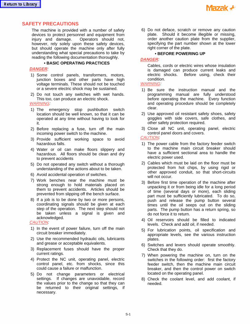
SAFETY PRECAUTIONSThe machine is provided with a number of safetydevices to protect personnel and equipment frominjury and damage. Operators should not,however, rely solely upon these safety devices,but should operate the machine only after fullyunderstanding what special precautions to take byreading the following documentation thoroughly.
• BASIC OPERATING PRACTICESDANGER:
1) Some control panels, transformers, motors,junction boxes and other parts have highvoltage terminals. These should not be touchedor a severe electric shock may be sustained.
2) Do not touch any switches with wet hands.This too, can produce an electric shock.
WARNING:
1) The emergency stop pushbutton switchlocation should be well known, so that it can beoperated at any time without having to look forit.
2) Before replacing a fuse, turn off the mainincoming power switch to the machine.
3) Provide sufficient working space to avoidhazardous falls.
4) Water or oil can make floors slippery andhazardous. All floors should be clean and dryto prevent accidents
5) Do not operated any switch without a thoroughunderstanding of the actions about to be taken.
6) Avoid accidental operation of switches.7) Work benches near the machine must be
strong enough to hold materials placed onthem to prevent accidents. Articles should beprevented from slipping off the bench surface.
8) If a job is to be done by two or more persons,coordinating signals should be given at eachstep of the operation. The next step should notbe taken unless a signal is given andacknowledged.
CAUTION:
1) In the event of power failure, turn off the maincircuit breaker immediately.
2) Use the recommended hydraulic oils, lubricantsand grease or acceptable equivalents.
3) Replacement fuses should have the propercurrent ratings.
4) Protect the NC unit, operating panel, electriccontrol panel, etc. from shocks, since thiscould cause a failure or malfunction.
5) Do not change parameters or electricalsettings. If changes are unavoidable, recordthe values prior to the change so that they canbe returned to their original settings, ifnecessary.
6) Do not deface, scratch or remove any cautionplate. Should it become illegible or missing,order another caution plate from the supplier,specifying the part number shown at the lowerright corner of the plate.
• BEFORE POWERING UPDANGER:
Cables, cords or electric wires whose insulationis damaged can produce current leaks andelectric shocks. Before using, check theircondition.
WARNING:
1) Be sure the instruction manual and theprogramming manual are fully understoodbefore operating the machine. Every functionand operating procedure should be completelyclear.
2) Use approved oil resistant safety shoes, safetygoggles with side covers, safe clothes, andother safety protection required.
3) Close all NC unit, operating panel, electriccontrol panel doors and covers.
CAUTION:
1) The power cable from the factory feeder switchto the machine main circuit breaker shouldhave a sufficient sectional area to handle theelectric power used.
2) Cables which must be laid on the floor must beprotected from hot chips, by using rigid orother approved conduit, so that short-circuitswill not occur.
3) Before first time operation of the machine afterunpacking it or from being idle for a long periodof time (several days or more), each slidingpart must be sufficiently lubricated. To do so,push and release the pump button severaltimes until the oil seeps out on the slidingparts. The pump button has a return spring, sodo not force it to return.
4) Oil reservoirs should be filled to indicatedlevels. Check and add oil, if needed.
5) For lubrication points, oil specification andappropriate levels, see the various instructionplates.
6) Switches and levers should operate smoothly.Check that they do.
7) When powering the machine on, turn on theswitches in the following order: first the factoryfeeder switch, then the machine main circuitbreaker, and then the control power on switchlocated on the operating panel.
8) Check the coolant level, and add coolant, ifneeded.
S-1
• AFTER CONTROL POWER IS TURNED ONCAUTION:
When the control power “ON” switch on theoperating panel is on, the "READY" lamp onthe operating panel should also be on (check tosee that it is).
• ROUTINE INSPECTIONSWARNING:
When checking belt tensions, do not get yourfingers caught between the belt and pulley.
CAUTION:
1) Check pressure gages for proper readings.2) Check motors, gear boxes and other parts for
abnormal noises.3) Check the motor lubrication, and sliding parts
for evidence of proper lubrication.4) Check safety covers and safety devices for
proper operation.5) Check belt tensions. Replace any set of belts
that have become stretched with a freshmatching set.
• WARM UPCAUTION:
1) Warm up the machine, especially the spindleand feed shaft, by running the machine for 10to 20 minutes at about one-half or one-third themaximum speed in the automatic operationmode.
2) The automatic operation program should causeeach machine component to operate. At thesame time, check their operations.
3) Be particularly careful to warm up the spindlewhich can turn above 4000 rpm.If the machine is used for actual machiningimmediately after being started up following along idle period, the sliding parts may be worndue to the lack of oil. Also, thermal expansionof the machine components can jeopardizemachining accuracy. To prevent this condition,always make sure that the machine is warmedup.
• PREPARATIONSWARNING:
1) Tooling should conform to the machinespecifications, dimensions and types.
2) Replace all seriously worn tools with new onesto prevent injuries.
3) The work area should be adequately lighted tofacilitate safety checks.
4) Tools and other items around the machine orequipment should be stored to ensure goodfooting and clear aisles.
5) Do not place tools or any other items on theheadstock, turret, covers and similar places(For T/M).
CAUTION:
1) Tool lengths should be within specifiedtolerances to prevent interference.
2) After installing a tool, make a trial run.
• OPERATIONWARNING:
1) Do not work with long hair that can be caughtby the machine. Tie it back, out of the way.
2) Do not operate switches with gloves on. Thiscould cause mis-operation.
3) Whenever a heavy workpiece must be moved,if there is any risk involved, two or more peopleshould work together.
4) Only trained, qualified workers should operateforklift trucks, cranes or similar equipment andapply slings.
5) Whenever operating a forklift truck, crane orsimilar equipment, special care should be takento prevent collisions and damage to thesurroundings.
6) Wire ropes or slings should be strong enoughto handle the loads to be lifted and shouldconform to the mandatory provisions.
7) Grip workpieces securely.8) Stop the machine before adjusting the coolant
nozzle at the tip.9) Never touch a turning workpiece in the spindle
with bare hands, or in any other way.10) To remove a workpiece from the machine other
than by a pallet changer, stop the tool andprovide plenty of distance between theworkpiece and the tool (for M/C).
11) While a workpiece or tool is turning, do notwipe it off or remove chips with a cloth or byhand. Always stop the machine first and thenuse a brush and a sweeper.
12) Do not operate the machine with the chuck andfront safety covers removed (For T/M).
13) Use a brush to remove chips from the tool tip,do not use bare hands .
14) Stop the machine whenever installing orremoving a tool.
15) Whenever machining magnesium alloy parts,wear a protective mask.
S-2
CAUTION:
1) During automatic operation, never open themachine door. Machines equipped with thedoor interlock will set the program to singlestep.
2) When performing heavy-duty machining,carefully prevent chips from being accumulatedsince hot chips from certain materials cancause a fire.
• TO INTERRUPT MACHININGWARNING:
When leaving the machine temporarily aftercompleting a job, turn off the power switch onthe operation panel, and also the main circuitbreaker.
• COMPLETING A JOBCAUTION:
1) Always clean the machine or equipment.Remove and dispose of chips and clean coverwindows, etc.
2) Make sure the machine has stopped running,before cleaning.
3) Return each machine component to its initialcondition.
4) Check the wipers for breakage. Replacebroken wipers.
5) Check the coolant, hydraulic oils and lubricantsfor contamination. Change them if they areseriously contaminated.
6) Check the coolant, hydraulic oil and lubricantlevels. Add if necessary.
7) Clean the oil pan filter.8) Before leaving the machine at the end of the
shift, turn off the power switch on the operatingpanel, machine main circuit breaker and factoryfeeder switch in that order.
• SAFETY DEVICES1) Front cover, rear cover and coolant cover.2) Chuck barrier, tail barrier and tool barrier (NC
software).3) Stored stroke limit (NC software).4) Emergency stop pushbutton switch.
• MAINTENANCE OPERATION PREPARATIONS1) Do not proceed to do any maintenance
operation unless instructed to do so by theforeman.
2) Replacement parts, consumables (packing, oilseals, O rings, bearing, oil and grease, etc.)Should be arranged in advance.
3) Prepare preventive maintenance and recordmaintenance programs.
CAUTION:
1) Thoroughly read and understand the safetyprecautions in the instruction manual.
2) Thoroughly read the whole maintenancemanual and fully understand the principles,construction and precautions involved.
• MAINTENANCE OPERATIONDANGER:1) Those not engaged in the maintenance work
should not operate the main circuit breaker orthe control power "ON" switch on theoperating panel. For this purpose, "Do notTouch the Switch, Maintenance Operation inProgress!" or similar warning should beindicated on such switches and at any otherappropriate locations. Such indication shouldbe secured by a semi-permanent means in thereading direction.
2) With the machine turned on, any maintenanceoperation can be dangerous. In principle, themain circuit breaker should be turned offthroughout the maintenance operation.
WARNING:
1) The electrical maintenance should be done bya qualified person or by others competent to dothe job. Keep close contact with theresponsible person. Do not proceed alone.
2) Overtravel limit and proximity switches andinterlock mechanisms including functional partsshould not be removed or modified.
3) When working at a height, use steps or ladderswhich are maintained and controlled daily forsafety.
4) Fuses, cables, etc. made by qualifiedmanufacturers should be employed.
• BEFORE OPERATION & MAINTENANCE BEGINSWARNING:
1) Arrange things in order around the section toreceive the maintenance, including workingenvironments. Wipe water and oil off parts andprovide safe working environments.
2) All parts and waste oils should be removed bythe operator and placed far enough away fromthe machine to be safe.
CAUTION:
1) The maintenance person should check that themachine operates safely.
2) Maintenance and inspection data should berecorded and kept for reference.
000X717-KY 11/98
S-3
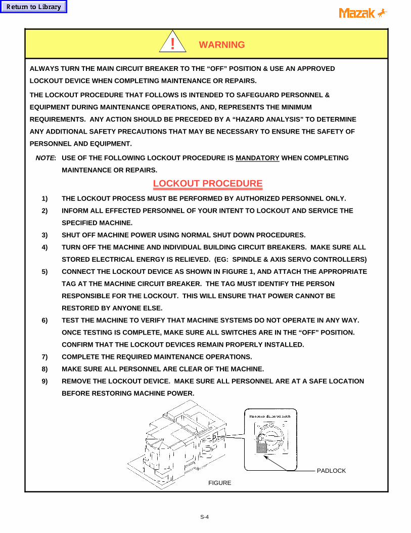
ALWAYS TURN THE MAIN CIRCUIT BREAKER TO THE “OFF” POSITION & USE AN APPROVED
LOCKOUT DEVICE WHEN COMPLETING MAINTENANCE OR REPAIRS.
THE LOCKOUT PROCEDURE THAT FOLLOWS IS INTENDED TO SAFEGUARD PERSONNEL &
EQUIPMENT DURING MAINTENANCE OPERATIONS, AND, REPRESENTS THE MINIMUM
REQUIREMENTS. ANY ACTION SHOULD BE PRECEDED BY A “HAZARD ANALYSIS” TO DETERMINE
ANY ADDITIONAL SAFETY PRECAUTIONS THAT MAY BE NECESSARY TO ENSURE THE SAFETY OF
PERSONNEL AND EQUIPMENT.
NOTE: USE OF THE FOLLOWING LOCKOUT PROCEDURE IS MANDATORY WHEN COMPLETING
MAINTENANCE OR REPAIRS.
LOCKOUT PROCEDURE
1) THE LOCKOUT PROCESS MUST BE PERFORMED BY AUTHORIZED PERSONNEL ONLY.
2) INFORM ALL EFFECTED PERSONNEL OF YOUR INTENT TO LOCKOUT AND SERVICE THE
SPECIFIED MACHINE.
3) SHUT OFF MACHINE POWER USING NORMAL SHUT DOWN PROCEDURES.
4) TURN OFF THE MACHINE AND INDIVIDUAL BUILDING CIRCUIT BREAKERS. MAKE SURE ALL
STORED ELECTRICAL ENERGY IS RELIEVED. (EG: SPINDLE & AXIS SERVO CONTROLLERS)
5) CONNECT THE LOCKOUT DEVICE AS SHOWN IN FIGURE 1, AND ATTACH THE APPROPRIATE
TAG AT THE MACHINE CIRCUIT BREAKER. THE TAG MUST IDENTIFY THE PERSON
RESPONSIBLE FOR THE LOCKOUT. THIS WILL ENSURE THAT POWER CANNOT BE
RESTORED BY ANYONE ELSE.
6) TEST THE MACHINE TO VERIFY THAT MACHINE SYSTEMS DO NOT OPERATE IN ANY WAY.
ONCE TESTING IS COMPLETE, MAKE SURE ALL SWITCHES ARE IN THE “OFF” POSITION.
CONFIRM THAT THE LOCKOUT DEVICES REMAIN PROPERLY INSTALLED.
7) COMPLETE THE REQUIRED MAINTENANCE OPERATIONS.
8) MAKE SURE ALL PERSONNEL ARE CLEAR OF THE MACHINE.
9) REMOVE THE LOCKOUT DEVICE. MAKE SURE ALL PERSONNEL ARE AT A SAFE LOCATION
BEFORE RESTORING MACHINE POWER.
FIGURE
WARNING
a a a
a a a
a a a
a a a
a a a!
PADLOCK
S-4
INSTALLATION PRECAUTIONSThe following subjects outline the items thatdirectly affect the machine installation and start-up. To ensure an efficient and timely installation,please follow these recommendations beforecalling to schedule a service engineer.
• ENVIRONMENTAL REQUIREMENTSAvoid the following places for installing themachine:
1) Avoid exposure to direct sunlight and/or near aheat source, etc. Ambient temperature duringoperation: 0° thru 45°C (32°F to 113°F).
2) Avoid areas where the humidity fluctuatesgreatly and/or if high humidity is present;normally 75% and below in relative humidity. Ahigher humidity deteriorates insulation andmight accelerate the deterioration of parts.
3) Avoid areas that are especially dusty and/orwhere acid fumes, corrosive gases and salt arepresent.
4) Avoid areas of high vibration.5) Avoid soft or weak ground (minimum load
bearing capacity of 1025 lbs./ft 2)
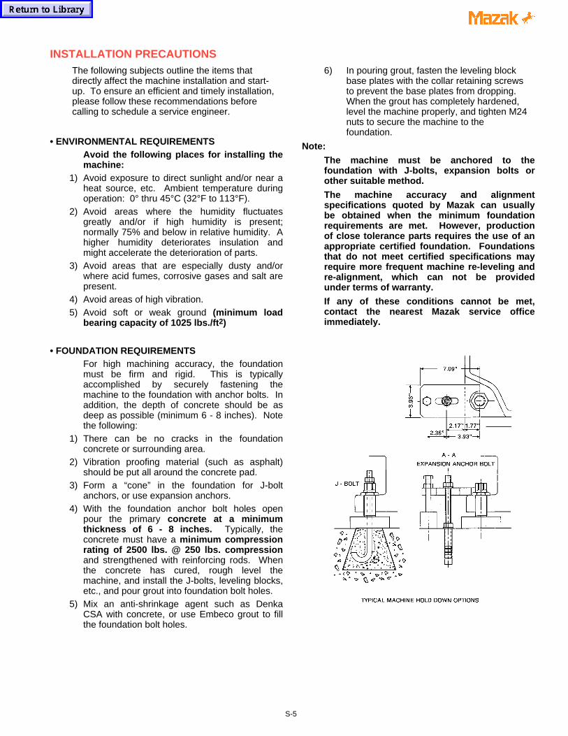
• FOUNDATION REQUIREMENTSFor high machining accuracy, the foundationmust be firm and rigid. This is typicallyaccomplished by securely fastening themachine to the foundation with anchor bolts. Inaddition, the depth of concrete should be asdeep as possible (minimum 6 - 8 inches). Notethe following:
1) There can be no cracks in the foundationconcrete or surrounding area.
2) Vibration proofing material (such as asphalt)should be put all around the concrete pad.
3) Form a “cone” in the foundation for J-boltanchors, or use expansion anchors.
4) With the foundation anchor bolt holes openpour the primary concrete at a minimumthickness of 6 - 8 inches. Typically, theconcrete must have a minimum compressionrating of 2500 lbs. @ 250 lbs. compressionand strengthened with reinforcing rods. Whenthe concrete has cured, rough level themachine, and install the J-bolts, leveling blocks,etc., and pour grout into foundation bolt holes.
5) Mix an anti-shrinkage agent such as DenkaCSA with concrete, or use Embeco grout to fillthe foundation bolt holes.
6) In pouring grout, fasten the leveling blockbase plates with the collar retaining screwsto prevent the base plates from dropping. When the grout has completely hardened,level the machine properly, and tighten M24nuts to secure the machine to thefoundation.
Note:
The machine must be anchored to thefoundation with J-bolts, expansion bolts orother suitable method.
The machine accuracy and alignmentspecifications quoted by Mazak can usuallybe obtained when the minimum foundationrequirements are met. However, productionof close tolerance parts requires the use of anappropriate certified foundation. Foundationsthat do not meet certified specifications mayrequire more frequent machine re-leveling andre-alignment, which can not be providedunder terms of warranty.
If any of these conditions cannot be met,contact the nearest Mazak service officeimmediately.
S-5
• WIRING
1) Use only electrical conductors withperformance ratings equivalent or superior.
2) Do not connect any power cables for deviceswhich can cause line noise to the powerdistribution panel, such as arc welders and highfrequency machinery.
3) Arrange for a qualified electrician to connectthe power lines.
4) Incoming supply voltage should not deviatemore than ±10% of specified supply voltage.
5) Source frequency should be±2 Hz of nominalfrequency.
[ CAUTION ]
VERIFY THE ACTUAL MACHINE ELECTRICAL
POWER REQUIREMENT AND THE MAIN
TRANSFORMER RATING (IF APPLICABLE), AS
WELL AS THE LOCAL ELECTRICAL CODE
BEFORE SIZING AND INSTALLING THE
INCOMING POWER WIRING.
PLEASE SEE THE ADDITIONAL CAUTIONS ON
THE FOLLOWING PAGE.
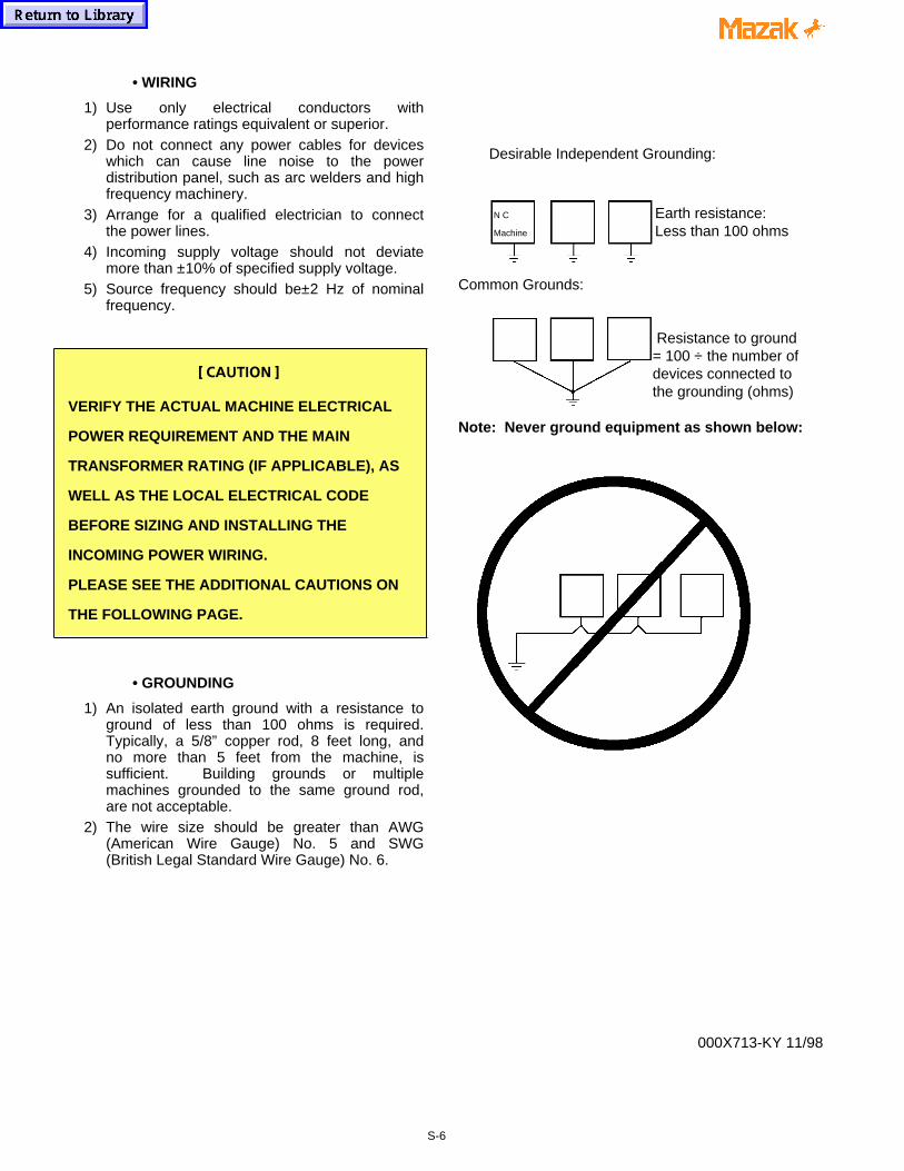
• GROUNDING
1) An isolated earth ground with a resistance toground of less than 100 ohms is required.Typically, a 5/8” copper rod, 8 feet long, andno more than 5 feet from the machine, issufficient. Building grounds or multiplemachines grounded to the same ground rod,are not acceptable.
2) The wire size should be greater than AWG(American Wire Gauge) No. 5 and SWG(British Legal Standard Wire Gauge) No. 6.
Desirable Independent Grounding:
N C Earth resistance:Machine Less than 100 ohms
Common Grounds:
Resistance to ground= 100 ÷ the number ofdevices connected tothe grounding (ohms)
Note: Never ground equipment as shown below:
000X713-KY 11/98
S-6
A step-down transformer is optional on some machine models. Be certain to
verify the transformer Kva rating (where applicable), as well as local electrical
code requirements before sizing and installing the incoming power wiring.
Machines not equipped with a main transformer are wired for 230 VAC, 3 phase.
The end user must supply a step-down transformer where factory electrical
power varies more than ± 10% of the 230 VAC rating.
NOTE:
Step-down or voltage regulating transformers are external (peripheral) to the
machine tool and are considered the primary input line (source) for the machine.
Local electrical code or practice may require a circuit breaker or other switching
device for the isolation of electrical power when this type of transformer is used.
In such cases, the machine tool end user is required to supply the necessary
circuit breaker or switching device.
FAILURE TO COMPLY CAN RESULT IN PERSONAL INJURY AND DAMAGE TO THEMACHINE. IF ANY QUESTION EXISTS, CONTACT THE NEAREST MAZAK SERVICECENTER FOR ASSISTANCE.
CAUTION!
S-7
MAZATROL CNC CONTROLLERS PROVIDE PARAMETER SETTINGS TO LIMIT SPINDLERPM. THESE SETTINGS ARE BASED ON THE MAXIMUM SPEED SPECIFIED BY THECHUCK/ACTUATOR MANUFACTURER.
MAKE SURE TO SET THESE PARAMETERS ACCORDING TO CHUCK SPECIFICATIONWHEN INSTALLING A CHUCKING PACKAGE. ALSO, STAMP THE MAXIMUM SPINDLERPM ON THE CHUCK IDENTIFICATION PLATE LOCATED ON THE MACHINE TOOLCOVERS.
REFERENCE THE CNC PARAMETER MANUAL SUPPLIED WITH THE SPECIFIC MACHINETOOL TO IDENTIFY THE REQUIRED PARAMETERS TO CHANGE.
FAILURE TO COMPLY WITH THESE INSTRUCTIONS COULD RESULT IN DAMAGE TOTHE MACHINE, SERIOUS INJURY OR DEATH.
IF ANY QUESTIONS EXIST, CONTACT THE NEAREST MAZAK SERVICE CENTER FORASSISTANCE.
S-8
MAZAK MACHINES ARE ENGINEERED WITH A NUMBER OF SAFETY DEVICES TOPROTECT PERSONNEL AND EQUIPMENT FROM INJURY AND DAMAGE.
DO NOT REMOVE, DISCONNECT, BYPASS OR MODIFY ANY LIMIT SWITCH, INTERLOCK,COVER, OR OTHER SAFETY FEATURE IN ANY WAY, EITHER MECHANICALLY ORELECTRICALLY.
FAILURE TO COMPLY WITH THESE INSTRUCTIONS COULD RESULT IN DAMAGE TOTHE MACHINE, SERIOUS INJURY OR DEATH.
IF ANY QUESTIONS EXIST, CONTACT THE NEAREST MAZAK SERVICE CENTER FORASSISTANCE.
WARNING!
WARNING!
MAZAK MACHINES ARE ENGINEERED WITH A NUMBER OF SAFETY DEVICES TOPROTECT PERSONNEL AND EQUIPMENT FROM INJURY AND DAMAGE.
MACHINE OPERATOR DOORS AND COVERS ARE DESIGNED TO WITHSTANDACCIDENTAL IMPACT OF A BROKEN INSERT WHERE A MAXIMUM WEIGHT INSERT ATMAXIMUM TOOL DIAMETER IS RUNNING AT MAXIMUM SPINDLE RPM
NEVER USE A CUTTING TOOL OR TOOL INSERT THAT EXCEEDS MACHINESPECIFICATIONS OR THAT OF A SPECIFIC TOOL HOLDER ITSELF, WHICHEVER IS LESS.THIS RESTRICTION APPLIES TO DIAMETER, WEIGHT, MAXIMUM SPINDLE RPM,MAXIMUM CUTTING TOOL ROTATION SPEED, ETC.
FOR COMPLETE SPECIFICATIONS, MAKE SURE TO REFERENCE OPERATION,MAINTENANCE AND DETAIL SPECIFICATION DOCUMENTATION SUPPLIED WITH THEMACHINE AND BY THE TOOLING MANUFACTURER.
NOTE: THE MAXIMUM INSERT WEIGHT FOR MAZAK MACHINES IS 20 gf. (0.04 lbs.).
FAILURE TO COMPLY WITH THESE INSTRUCTIONS COULD RESULT IN DAMAGE TOTHE MACHINE, SERIOUS INJURY OR DEATH.
IF ANY QUESTIONS EXIST, CONTACT THE NEAREST MAZAK SERVICE CENTER FORASSISTANCE.
S-9
WARNING!
WARNING!CONFIRM PROPER WORKPIECE FIXTURING/CLAMPING, TOOL SETUP AND THAT THEMACHINE DOOR IS SECURELY CLOSED BEFORE THE START OF MACHINING.
VERIFY ALL SAFETY PRECAUTIONS OUTLINED IN THIS MANUAL BEFORE USING THEFOLLOWING CUTTING CONDITIONS:
- CUTTING CONDITIONS THAT ARE THE RESULT OF THE MAZATROL FUSION 640AUTOMATIC CUTTING DETERMINATION FUNCTION
- CUTTING CONDITIONS SUGGESTED BY THE MACHINING NAVAGATION FUNCTION
- CUTTING CONDITIONS FOR TOOLS THAT ARE SUGGESTED TO BE USED BY THEMACHINING NAVAGATION FUNCTION
FAILURE TO COMPLY WITH THESE INSTRUCTIONS COULD RESULT IN DAMAGE TOTHE MACHINE, SERIOUS INJURY OR DEATH.
IF ANY QUESTIONS EXIST, CONTACT THE NEAREST MAZAK SERVICE CENTER FORASSISTANCE.
BEFORE STARTING OPERATION, CHECK THAT THE WORKPIECE IS SECURELY MOUNTEDIN A VISE OR A SUITABLE FIXTURE. BE CERTAIN THAT THE MOUNTING IS SUFFICIENTTO WITHSTAND CUTTING FORCES DURING WORKPIECE MACHINING.
FAILURE TO COMPLY WITH THESE INSTRUCTIONS COULD RESULT IN DAMAGE TOTHE MACHINE, SERIOUS INJURY OR DEATH.
IF ANY QUESTIONS EXIST, CONTACT THE NEAREST MAZAK SERVICE CENTER FORASSISTANCE.
WARNING!
S-10

a aa aa aa aa aa aa aa aa aa aa aa aa aa aa aa aa aa aa aa aa aa aa aa aa aa aa aa aa aa aa aa aa aa aa aa aa aa aa aa aa aa aa aa aa aa aa aa aa aa aa aa aa aa aa aa aa aa aa aa aa aa aa aa aa aa aa aa aa aa aa aa aa aa aa aa aa aa aa aa aa aa aa aa aa aa aa aa aa aa aa aa aa aa aa aa aa aa aa aa aa aa aa aa aa aa aa aa aa aa aa aa aa aa aa aa aa aa aa aa aa aa aa aa aa aa aa aa aa aa aa aa aa aa aa aa aa aa aa aa aa aa aa aa aa aa aa aa aa aa aa aa aa aa aa aa aa aa aa aa aa aa aa aa aa aa aa aa aa aa aa aa aa aa aa aa aa aa aa aa aa aa aa aa aa aa a
Your opinion is important to enable us to issue documentation that will fit your needs.Thank you for taking the time to supply this information.
Machine Type: Machine Serial#: NC Type:
Customer: Reported By:
Address: Position:
Telephone#:
Manual Publication #:
How well is the documentation suited to your needs?
Were you able to find the necessary information easily?
How well are the manuals organized?
How easy are the manuals to understand?
Are the illustrations helpful?
Overall, how do you rate the documentation?
What did you like about the documentation? How can it be improved?
MACHINE DOCUMENTATIONCUSTOMER EVALUATION The Other Thoroughbred From Kentucky
Date:
Excellent Good Adequate Fair Poor
RETURN TO: MAZAK CorporationTechnical Publication Dept.8025 Production DriveFlorence, Kentucky 41042
a a a a a a a a a a a a a a a a a a a a a a a a a a a a a a a a a a a a a a a a a a a a a a a a a a a a a a a a a a a a a a a a a a a a a a a a a a a a a a a a a a a a a a a a a a a a a a a a a a a a a a a a a a a a a a a a a a a a a a a a a a a a a a a a a a a a a a a a
a a a a a a a a a a a a a a a a a a a a a a a a a a a a a a a a a a a a a a a a a a a a a a a a a a a a a a a a a a a a a a a a a a a a a a a a a a a a a a a a a a a a a a a a a a a a a a a a a a a a a a a a a a a a a a a a a a a a a a a a a a a a a a a a a a a a a a a a
a a a a a a a a a a a a a a a a a a a a a a a a a a a a a a a a a a a a a a a a a a a a a a a a a a a a a a a a a a a a a a a a a a a a a a a a a a a a a a a a a a a a a a a a a a a a a a a a a a a a a a a a a a a a a a a a a a a a a a a a a a a a a a a a a a a a a a a a
SF-202Xa

Notes:

Section 1:
Introduction

Notes:
C-1
TABLE OF CONTENTS(ABOUT THIS MANUAL)
Page
1 INTRODUCTION ....................................................................................1-1
1-1 List of Related Manuals and Documents............................................................ 1-1
1-2 Pagination .......................................................................................................... 1-1
1-3 Numbering of Figures and Tables...................................................................... 1-2
2 SAFETY PRECAUTIONS.......................................................................2-1
2-1 Rule ................................................................................................................... 2-1
2-2 Basic Safety Items ............................................................................................. 2-1
2-3 Clothing and Personal Safety............................................................................. 2-3
2-4 Operational Safety ............................................................................................. 2-3
2-5 Safety Considerations Relating to Holding Workpieces and Tooling ................. 2-4
2-6 Maintenance Safety ........................................................................................... 2-5
2-7 Workplace Safety............................................................................................... 2-6
2-8 Safety Considerations Relating to Chip Conveyor ............................................. 2-6
2-9 Safety Equipment............................................................................................... 2-7
2-10 Remarks on the Cutting Conditions Recommended by the NC ......................... 2-8
2-11 Safety Nameplates............................................................................................. 2-8

C-2
- MEMO -
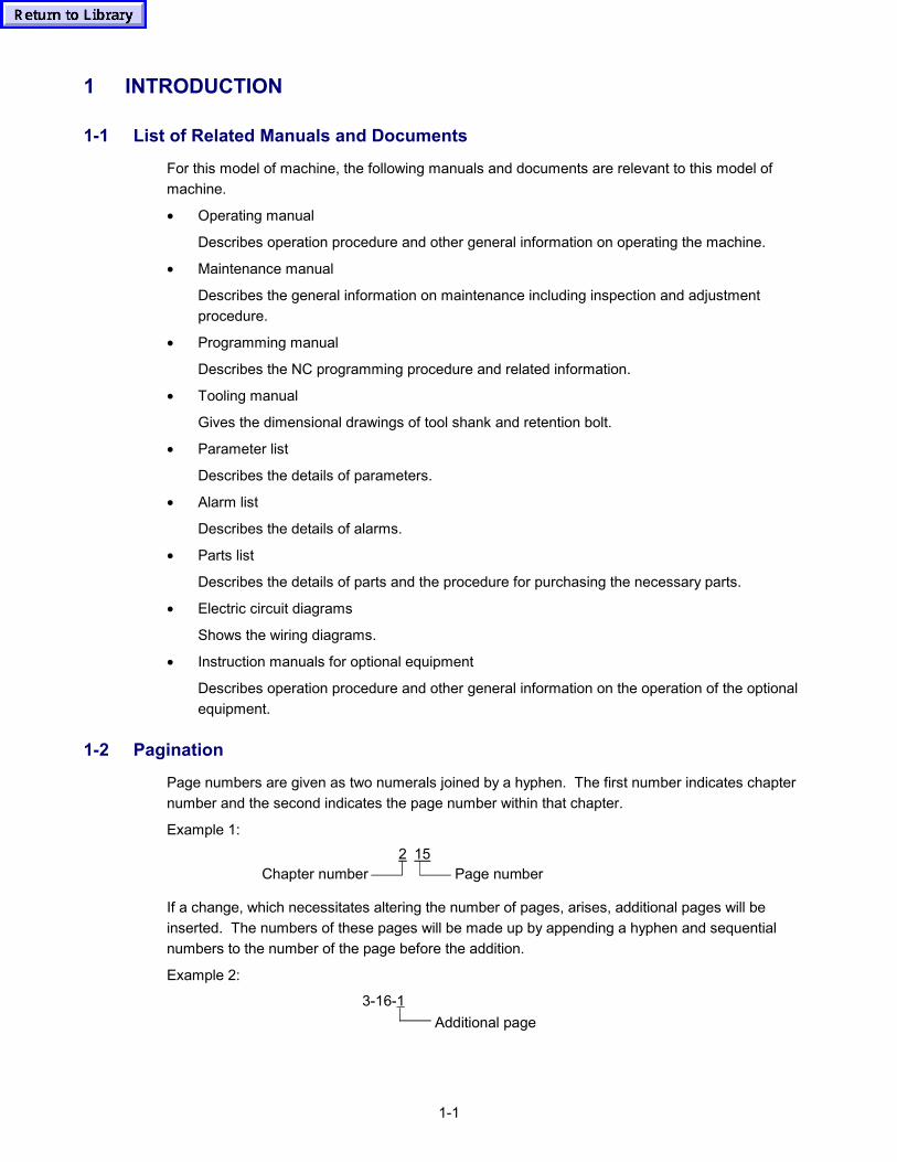
1-1
1 INTRODUCTION
1-1 List of Related Manuals and Documents
For this model of machine, the following manuals and documents are relevant to this model ofmachine.
• Operating manual
Describes operation procedure and other general information on operating the machine.
• Maintenance manual
Describes the general information on maintenance including inspection and adjustmentprocedure.
• Programming manual
Describes the NC programming procedure and related information.
• Tooling manual
Gives the dimensional drawings of tool shank and retention bolt.
• Parameter list
Describes the details of parameters.
• Alarm list
Describes the details of alarms.
• Parts list
Describes the details of parts and the procedure for purchasing the necessary parts.
• Electric circuit diagrams
Shows the wiring diagrams.
• Instruction manuals for optional equipment
Describes operation procedure and other general information on the operation of the optionalequipment.
1-2 Pagination
Page numbers are given as two numerals joined by a hyphen. The first number indicates chapternumber and the second indicates the page number within that chapter.
Example 1:2 15
Page numberChapter number
If a change, which necessitates altering the number of pages, arises, additional pages will beinserted. The numbers of these pages will be made up by appending a hyphen and sequentialnumbers to the number of the page before the addition.
Example 2:
3-16-1Additional page
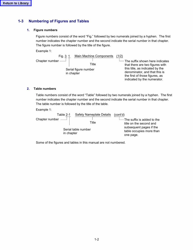
1-2
1-3 Numbering of Figures and Tables
1. Figure numbers
Figure numbers consist of the word “Fig.” followed by two numerals joined by a hyphen. The firstnumber indicates the chapter number and the second indicate the serial number in that chapter.The figure number is followed by the title of the figure.
Example 1:Fig. 3 1 Main Machine Components (1/2)
Serial figure numberin chapter
Chapter numberTitle
The suffix shown here indicatesthat there are two figures withthis title, as indicated by thedenominator, and that this isthe first of those figures, asindicated by the numerator.
2. Table numbers
Table numbers consist of the word “Table” followed by two numerals joined by a hyphen. The firstnumber indicates the chapter number and the second indicate the serial number in that chapter.The table number is followed by the title of the table.
Example 1:Table 2-1 Safety Nameplate Details (cont’d)
Serial table numberin chapter
Chapter numberTitle
The suffix is added to thetitle on the second andsubsequent pages if thetable occupies more thanone page.
Some of the figures and tables in this manual are not numbered.
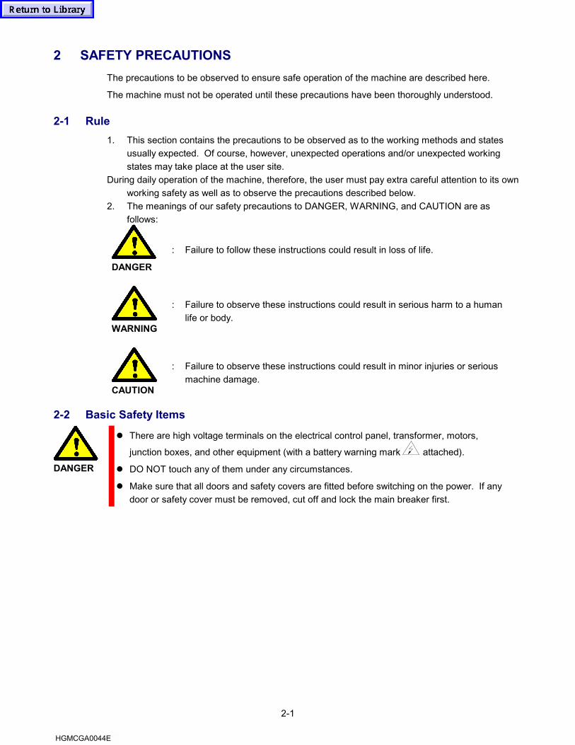
2-1
2 SAFETY PRECAUTIONSThe precautions to be observed to ensure safe operation of the machine are described here.
The machine must not be operated until these precautions have been thoroughly understood.
2-1 Rule1. This section contains the precautions to be observed as to the working methods and states
usually expected. Of course, however, unexpected operations and/or unexpected workingstates may take place at the user site.
During daily operation of the machine, therefore, the user must pay extra careful attention to its ownworking safety as well as to observe the precautions described below.
2. The meanings of our safety precautions to DANGER, WARNING, and CAUTION are asfollows:
DANGER
: Failure to follow these instructions could result in loss of life.
WARNING
: Failure to observe these instructions could result in serious harm to a humanlife or body.
CAUTION
: Failure to observe these instructions could result in minor injuries or seriousmachine damage.
2-2 Basic Safety Items
DANGER
� There are high voltage terminals on the electrical control panel, transformer, motors,
junction boxes, and other equipment (with a battery warning mark attached).
� DO NOT touch any of them under any circumstances.
� Make sure that all doors and safety covers are fitted before switching on the power. If anydoor or safety cover must be removed, cut off and lock the main breaker first.
HGMCGA0044E
2-2
WARNING
� Memorize the position of the EMERGENCY STOP button so that you can press itimmediately from any position.
� Take care not to touch any of the switches accidentally while the machine is in operation.
� Take care not to catch your fingers in the chuck. (For lathes)
� Never touch a rotating workpiece or the tool with your bare hands or any other object.
� To prevent incorrect operation of the machine, carefully check the position of the switchesbefore operation.
� If in the slightest doubt about a procedure, ask the person in charge.
� Always switch off the main power switch on the operation panel and the main powerbreaker when you are taking a break from work and are going to leave the machine.
� If more than one operator is using the machine, do not proceed to the next step withoutindicating to the other operator(s) that you are about to do so.
� Do not modify the machine in any way that will affect its safety.
� Do not enter the machine. If you have to enter the machine, take measures such aspressing the EMERGENCY STOP button that disable machine operation.
CAUTION
� If there is a power failure, switch off the main power breaker immediately.
� Do not subject the NC unit, the operation panel, or the electrical control panel to strongshocks.
� Do not change the parameter values, volume values, or other electrical setting valueswithout good reason. If you need to change a value, first check that it is safe to do so, thenmake a note of the original value so that it can be reset if necessary.
� Do not paint, soil, damage, modify, or remove any of the safety nameplates. If the detailsbecome illegible or the nameplate is lost, obtain a replacement by sending the part numberstamped at the bottom right-hand corner of the nameplate to Mazak and mount thereplacement in the original position. (If a nameplate has been lost, obtain the part numberfrom the “Parts List” supplied separately.)
� Do not open any doors or safety covers while the machine is in automatic operation.
� Stop all machine operations before cleaning the machine or any of the peripheralequipment.
� After a job has been completed, set up each part of the machine so that it is ready for thenext series of operations.
2-3
2-3 Clothing and Personal Safety
CAUTION
� Tie back long hair which could become entangled in drive mechanisms.
� Wear safety equipment (helmet, goggles, safety shoes, etc.) whenever possible.
� Always wear a helmet if there are any overhead obstacles in the work area.
� Always wear a protective mask when machining magnesium alloys.
� Always use safety shoes with steel toecaps and oil-resistant soles.
� Never wear loose or baggy clothing.
� Always completely fasten buttons and hooks on the arms of clothing to avoid the danger ofentanglement in drive mechanisms.
� Always use gloves when loading or unloading workpieces or tools and when removingchips from the work area to protect your hands from sharp edges and heat generatedduring machining.
� Do not operate the machine while under the influence of drugs with powerful effects,unprescribed drugs, or alcohol.
� Do not operate the machine if you suffer from dizziness or fainting spells.
2-4 Operational Safety
WARNING
� Close all doors and covers of the NC unit, operation panel, electrical control panel, andjunction boxes to prevent damage from water, chips, and oil.
� Check all electrical cables for damage to prevent accidents due to current leakage orelectric shock.
� Do not handle coolant with bare hands since it is liable to cause irritation. Operators withallergies should take special precautions.
� Do not operate the machine during violent thunderstorms.
� Check the safety covers regularly to make sure that they are properly filled and that theyare not damaged. Repair or replace any damaged covers immediately.
� Always obtain assistance in handling loads beyond your capacity.
� Do not operate fork lifts or cranes or carry out slinging work unless you have undergoneofficially approved training.
� When using fork lifts or cranes, make sure that there are no obstructions in the vicinity ofthese machines.
� Always use wire rope or slings of a standard suitable for the load to be supported.
� Wait until the machine has come to a complete stop before adjusting the position of thecoolant nozzle.
� Do not remove or otherwise interfere with safety equipment such as stop dogs, limitswitches, or interlocks in order to increase axis travel.
� Do not operate the machine with any of the safety covers removed.
� Always wear gloves and use a brush to clean chips off the tool tip; never use bare hands.
� Stop all machine operations before mounting or removing a tool.
� Check slings, chains, hoists, and other lifting gear for defects before use. Repair or replacedefective gear immediately.
2-4
CAUTION
� Do not allow chips to accumulate during heavy-duty cutting since they will be hot and couldstart a fire.
� Warm up the spindle and all of the axis motion mechanisms before operation. (Operatethe machine in the automatic mode for 10 to 20 minutes at maximum spindle speed or at1/3 to 1/2 maximum axis motion speed.)
� Write the program for the warming-up operation so as to execute the functions of the fullrange of machine components. If operation is to be performed at spindle speeds in excessof 4000 min–1, pay meticulous attention to the warming-up operation.
� Do not operate the operation panel switches while wearing gloves as this could lead toincorrect operation or other mistakes.
� When one series of operations is completed, switch off the power switch on the NCoperation panel, the main power breaker, then the factory power supply.
2-5 Safety Considerations Relating to Holding Workpieces and Tooling
WARNING
� Always use tools which are suitable for the work to be carried out and conform to themachine specifications. Always observe the restrictions on weight of tool insert and tooldiameter stipulated in the specifications. [Max. insert weight: 20 gf (0.04 lbs)]
� Replace tools promptly, since badly worn tools can cause accidents and injuries.
� Before starting operation, check that the workpiece is securely mounted and cannotbecome detached by the cutting forces applied to it during machining.
� Before mounting a cutting tool in the machine, make sure that the tool and its stud bolt areproperly secured.
� Do not rotate a cutting tool or holder at speeds higher than the rated speed.
� Check the maximum safe operating speed with the manufacturer.
� Be very careful not to catch your fingers in workpiece holding devices.
� Always use the correct lifting gear for heavy fixtures and workpieces.
CAUTION
� Make sure that cutting tools will not interfere with the workpiece fixture, etc.
� Mount the tool holder in the correct orientation by aligning it with the drive key.
� Occasionally check for looseness after using a milling chuck.
� Make sure that the workpiece is correctly mounted on the pallet or table.
� Check that vices, fixtures, etc., have no overhang with respect to the table.
� Make sure that the tools are arranged in the tool magazine correctly in accordance with thetool data set in the TOOL LAYOUT display.
� Check that the lengths of all tools to be used have been measured.
� Move the tool nose to the initial point (X0, Y0) to check the basic coordinate system.
� Perform a test operation after mounting a cutting tool and workpiece.
2-5
2-6 Maintenance Safety
DANGER
� Always switch off the main power breaker and lock it before carrying out any maintenancework. This will eliminate the possibility of the machinery being accidentally started bysomeone else.
� After the power has been switched off for a short while, check the voltage with a multimeteror similar instrument to make sure that there is no residual voltage. Also discharge thecapacitors.
WARNING
� Maintenance of electrical equipment must be carried out by qualified licensed electricalengineers only.
� Do not remove or modify limit switches, proximity switches, or other safety equipment.
� When carrying out maintenance in high places, always use a suitable ladder or a serviceplatform, and always wear a helmet.
� Always switch off the main power breaker and lock it before replacing bulbs or otherelectrical equipment, and use products with the same specifications as the original.
� Do not start the machine until all of the covers removed for maintenance have beenrefitted.
� Wipe up any water or oil spills immediately, and keep the maintenance area and theworkplace clean and tidy at all times.
CAUTION
� Maintenance work should be carried out by qualified personnel in accordance with theinstructions of the person in charge.
� Keep a stock of replacement parts and consumable items.
� Make sure you fully understand how to maintain the machine.
� Do not use compressed air to clean the machine or to remove chips.
� Always use gloves when clearing away chips; never touch chips with bare hands.
� Use only the specified grades of hydraulic oil, lubricating oil, and grease or theirequivalents
� When changing a fuse, check that the new fuse has the correct rating. (Using a fuse withtoo high a rating could result in damage to the equipment.)
� Follow the instructions on the instruction plate concerning the brands of oil to be used,lubrication points, amount to be used, and oil change intervals.
� Check the results of maintenance work in the presence of the person in charge.
� Stop all machine operation before cleaning the machine or the surrounding area.
2-6
2-7 Workplace Safety
WARNING
� Immediately remove all water and oil spills from the floor, and dry the floor to preventaccidents.
� Use strong service platforms only and make sure that nothing can slip off them.
� Keep combustible materials well away from the work area and any other place where thereare hot chips.
� Always provide sufficient lighting in the work area.
� Always provide sufficient working space and clear access to the machine and peripheralequipment and store tools and other potential obstacles in a prescribed place away fromthe machine.
� Never place tools or other potentially dangerous objects on top of the headstock, turrettool-post or covers. (For lathes)
� Make sure that the nominal cross-sectional area of the power supply cable between thefactory power supply switch and the machine main power breaker is such as to enable astable supply for operation at the maximum output.
� Protect all cables which will run along the floor from being damaged by chips, since thiscould cause short-circuiting.
2-8 Safety Considerations Relating to Chip Conveyor
WARNING
Before attempting any kind of work related to the chip conveyor, make sure that the chipconveyor is in a complete stop state with power supply shut off. Ignoring this will cause seriousinjury.While the chip conveyor is operating, never touch or extend your hands into any part of thechip conveyor. Ignoring this will cause your hands or fingers to be caught into the chipconveyor and injured seriously.

2-7
2-9 Safety Equipment
This machine is provided with various safety equipment to protect the operator and the machines.
The safety equipment include interlock devices and emergency stop switches, as well as doors andcovers.
WARNING
� The machine is provided with various devices for the operator’s safety.Never cancel any of the devices.Failure to observe this instruction could result in serious harm to a human life or body.
Arrangement of Safety Devices
No. Name Function
1 Operator’s door interlock 1. If the operator’s door is opened during automatic operation, the machine entersthe feed hold state with the spindle stopped.
2. While the operator’s door is open, spindle speed is restricted by the presetsafety speed.
2 Magazine door interlock 1. If the magazine door is opened while the magazine is operating, the magazinestops operating.
2. While the magazine door is open, the magazine cannot be operated.
3. While the magazine door is open, the magazine stops and the axes stopmovements.
3 Emergency stop buttons(2 places)
1. The emergency stop button is provided on each operation panel.
2. When the emergency stop button is pressed, the machine stops in theemergency stop state independent of the selected operation mode (automatic,manual).
4 Safety plate 1. A safety plate is fixed to the machine with screws to give operators and personsnearby warning information that standing near the movable area of equipmentand devices is dangerous.
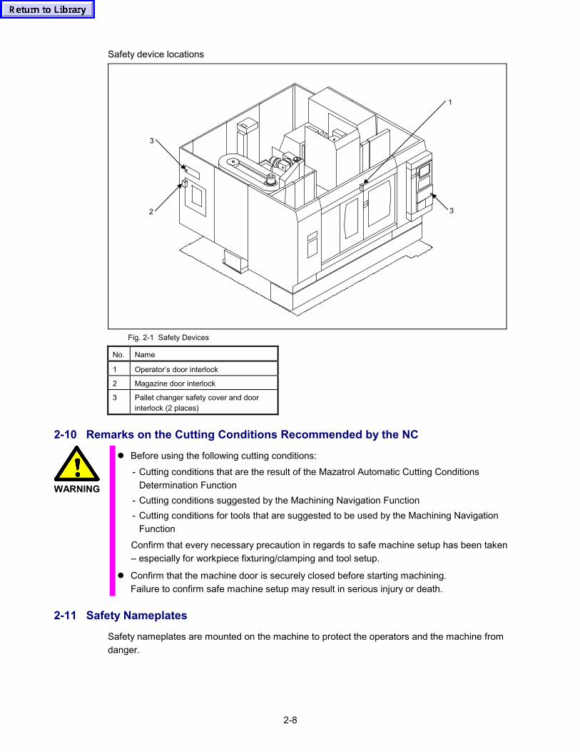
2-8
Safety device locations
1
3
3
2
Fig. 2-1 Safety Devices
No. Name
1 Operator’s door interlock
2 Magazine door interlock
3 Pallet changer safety cover and doorinterlock (2 places)
2-10 Remarks on the Cutting Conditions Recommended by the NC
WARNING
� Before using the following cutting conditions:
- Cutting conditions that are the result of the Mazatrol Automatic Cutting ConditionsDetermination Function
- Cutting conditions suggested by the Machining Navigation Function- Cutting conditions for tools that are suggested to be used by the Machining Navigation
Function
Confirm that every necessary precaution in regards to safe machine setup has been taken– especially for workpiece fixturing/clamping and tool setup.
� Confirm that the machine door is securely closed before starting machining.Failure to confirm safe machine setup may result in serious injury or death.
2-11 Safety Nameplates
Safety nameplates are mounted on the machine to protect the operators and the machine fromdanger.

Section 2:
Machine Operation

Notes:
C-1
TABLE OF CONTENTS(MACHINE OPERATION)
Page
1 OUTLINE OF THE MACHINE ................................................................1-1
1-1 Axis Definitions ..................................................................................................1-1
1-2 Names and Locations of Machine Units.............................................................1-2
2 OPERATION PANELS............................................................................2-1
2-1 Locations of Operation Panels ...........................................................................2-1
2-2 NC Operation Panel ...........................................................................................2-2
2-2-1 Arrangement of Switches on the NC Operation Panel ...........................................2-3
2-2-2 Names and Functions of Switches and Other Controls on the NC OperationPanel.....................................................................................................................2-4
2-3 Auxiliary Operation Panel...................................................................................2-9
2-4 Data Input/Output Panel...................................................................................2-10
2-5 Magazine Operation Panel...............................................................................2-11
2-6 Main Power Disconnect Switch........................................................................2-12
2-7 Operator’s Door Interlock .................................................................................2-13
2-7-1 MACHINE SET UP Switch (Key-lock Type Switch) .............................................2-13
3 MANUAL OPERATION...........................................................................3-1
3-1 Inspection before Starting Operation..................................................................3-1
3-2 Switching the Power ON ....................................................................................3-3
3-3 Inspection after Switching the Power ON...........................................................3-5
C-2
3-4 Switching the Power OFF ..................................................................................3-6
3-5 Zero-Point Return...............................................................................................3-7
3-6 Warmup Operation.............................................................................................3-9
3-7 Spindle Operation ............................................................................................3-10
3-7-1 Starting the Spindle .............................................................................................3-10
3-7-2 Stopping the Spindle ...........................................................................................3-10
3-7-3 Jogging the Spindle.............................................................................................3-10
3-7-4 Changing the Direction of Spindle Rotation .........................................................3-11
3-8 Feed Operation ................................................................................................3-11
3-8-1 Rapid Traverse Operation ...................................................................................3-11
3-8-2 Cutting Feed Operation .......................................................................................3-11
3-8-3 Pulse Handle Feed Operation .............................................................................3-12
3-8-4 Clearing the Soft-Limit Alarm...............................................................................3-13
3-9 Coolant System Operation ...............................................................................3-15
3-10 ATC Operation .................................................................................................3-16
3-10-1 Manual ATC Operation........................................................................................3-16
3-10-2 Recovering ATC Operation after Interruption.......................................................3-20
3-11 Chip Conveyor Operation (Optional Specifications) .........................................3-22
4 PREPARING FOR MACHINING ............................................................4-1
4-1 Procedure for Mounting or Removing a Tool in the Tool Magazine ...................4-1
4-1-1 Procedure for Mounting Tools to the Magazine .....................................................4-1
4-1-2 Procedure for Removing Tools from the Magazine................................................4-4
C-3
4-1-3 Restrictions on Tools.............................................................................................4-5
4-2 Mounting and Removing Workpieces.................................................................4-6
4-2-1 Dimensional Restrictions on Workpieces...............................................................4-6
4-2-2 Procedure for Mounting and Removing Workpieces..............................................4-7
4-2-3 Measuring Coordinate Values ...............................................................................4-7
4-3 Preparing Coolant ..............................................................................................4-8
4-3-1 Selection of Coolant ..............................................................................................4-8
4-3-2 Replenishing Coolant ............................................................................................4-8
4-4 Adjustment of Coolant Nozzle Direction.............................................................4-9

C-4
- MEMO -
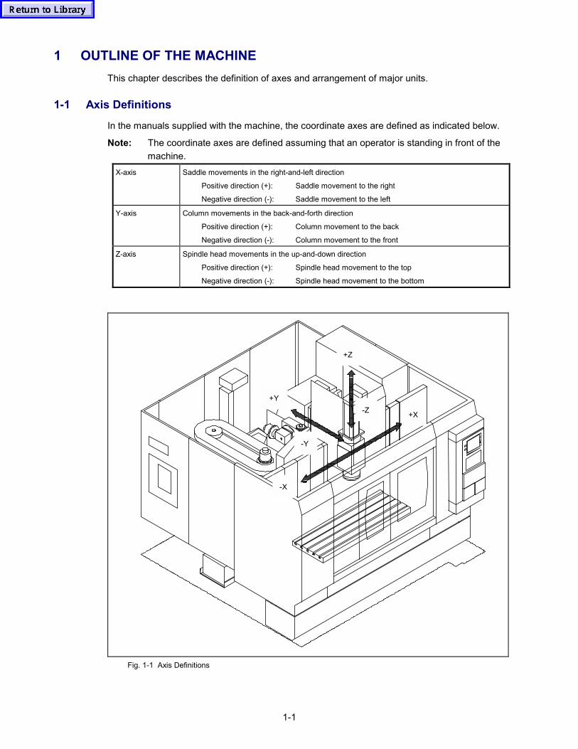
1-1
1 OUTLINE OF THE MACHINEThis chapter describes the definition of axes and arrangement of major units.
1-1 Axis Definitions
In the manuals supplied with the machine, the coordinate axes are defined as indicated below.
Note: The coordinate axes are defined assuming that an operator is standing in front of themachine.
X-axis Saddle movements in the right-and-left direction
Positive direction (+): Saddle movement to the right
Negative direction (-): Saddle movement to the left
Y-axis Column movements in the back-and-forth direction
Positive direction (+): Column movement to the back
Negative direction (-): Column movement to the front
Z-axis Spindle head movements in the up-and-down direction
Positive direction (+): Spindle head movement to the top
Negative direction (-): Spindle head movement to the bottom
+X
-X
-Z
+Z
-Y
+Y
Fig. 1-1 Axis Definitions
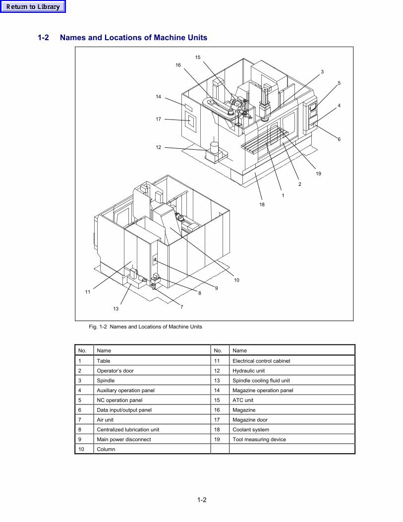
1-2
1-2 Names and Locations of Machine Units
1
2
3
4
5
6
7
89
1516
14
17
12
19
18
10
13
11
Fig. 1-2 Names and Locations of Machine Units
No. Name No. Name
1 Table 11 Electrical control cabinet
2 Operator’s door 12 Hydraulic unit
3 Spindle 13 Spindle cooling fluid unit
4 Auxiliary operation panel 14 Magazine operation panel
5 NC operation panel 15 ATC unit
6 Data input/output panel 16 Magazine
7 Air unit 17 Magazine door
8 Centralized lubrication unit 18 Coolant system
9 Main power disconnect 19 Tool measuring device
10 Column
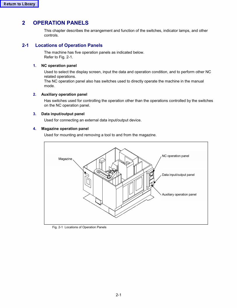
2-1
2 OPERATION PANELSThis chapter describes the arrangement and function of the switches, indicator lamps, and othercontrols.
2-1 Locations of Operation PanelsThe machine has five operation panels as indicated below.Refer to Fig. 2-1.
1. NC operation panelUsed to select the display screen, input the data and operation condition, and to perform other NCrelated operations.The NC operation panel also has switches used to directly operate the machine in the manualmode.
2. Auxiliary operation panelHas switches used for controlling the operation other than the operations controlled by the switcheson the NC operation panel.
3. Data input/output panelUsed for connecting an external data input/output device.
4. Magazine operation panelUsed for mounting and removing a tool to and from the magazine.
Magazine
Auxiliary operation panel
Data input/output panel
NC operation panel
Fig. 2-1 Locations of Operation Panels
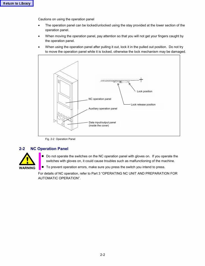
2-2
Cautions on using the operation panel
• The operation panel can be locked/unlocked using the stay provided at the lower section of theoperation panel.
• When moving the operation panel, pay attention so that you will not get your fingers caught bythe operation panel.
• When using the operation panel after pulling it out, lock it in the pulled out position. Do not tryto move the operation panel while it is locked, otherwise the lock mechanism may be damaged.
NC operation panel
Auxiliary operation panel
Data input/output panel(inside the cover)
Lock release position
Lock position
Fig. 2-2 Operation Panel
2-2 NC Operation Panel
WARNING
� Do not operate the switches on the NC operation panel with gloves on. If you operate theswitches with gloves on, it could cause troubles such as malfunctioning of the machine.
� To prevent operation errors, make sure you press the switch you intend to press.
For details of NC operation, refer to Part 3 “OPERATING NC UNIT AND PREPARATION FORAUTOMATIC OPERATION”.
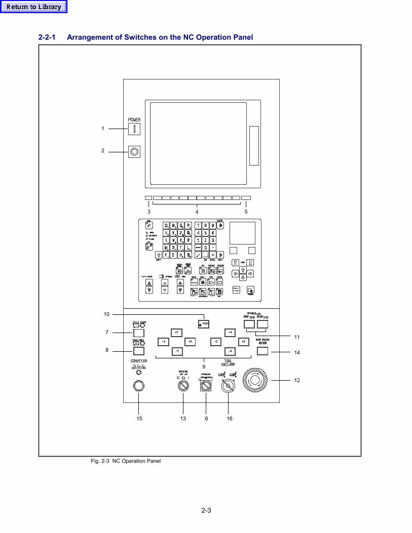
2-3
2-2-1 Arrangement of Switches on the NC Operation Panel
7
8
15
12
13 6 16
14
11
1
2
9
10
3 4 5
Fig. 2-3 NC Operation Panel
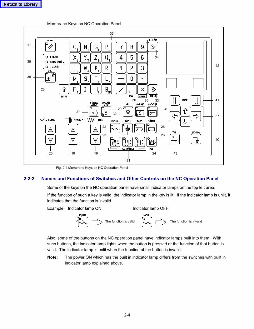
2-4
Membrane Keys on NC Operation Panel
1820 19 24
21
43
40
37
41
4239
38
17
28
27 3229
35
36 33
31
30
22 25
2623
34
Fig. 2-4 Membrane Keys on NC Operation Panel
2-2-2 Names and Functions of Switches and Other Controls on the NC Operation Panel
Some of the keys on the NC operation panel have small indicator lamps on the top left area.
If the function of such a key is valid, the indicator lamp in the key is lit. If the indicator lamp is unlit, itindicates that the function is invalid.
Example: Indicator lamp ON Indicator lamp OFF
The function is valid The function is invalid
Also, some of the buttons on the NC operation panel have indicator lamps built into them. Withsuch buttons, the indicator lamp lights when the button is pressed or the function of that button isvalid. The indicator lamp is unlit when the function of the button is invalid.
Note: The power ON which has the built in indicator lamp differs from the switches with built inindicator lamp explained above.
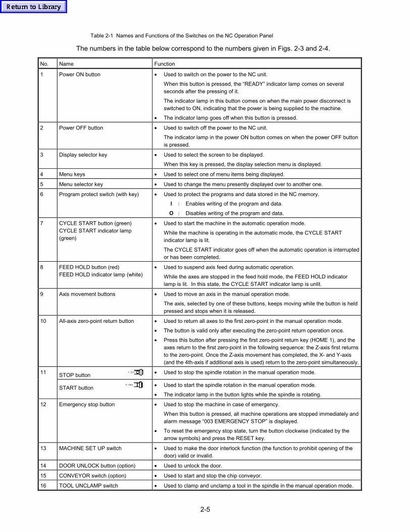
2-5
Table 2-1 Names and Functions of the Switches on the NC Operation Panel
The numbers in the table below correspond to the numbers given in Figs. 2-3 and 2-4.
No. Name Function
1 Power ON button • Used to switch on the power to the NC unit.
When this button is pressed, the “READY” indicator lamp comes on severalseconds after the pressing of it.
The indicator lamp in this button comes on when the main power disconnect isswitched to ON, indicating that the power is being supplied to the machine.
• The indicator lamp goes off when this button is pressed.
2 Power OFF button • Used to switch off the power to the NC unit.
The indicator lamp in the power ON button comes on when the power OFF buttonis pressed.
3 Display selector key • Used to select the screen to be displayed.
When this key is pressed, the display selection menu is displayed.
4 Menu keys • Used to select one of menu items being displayed.
5 Menu selector key • Used to change the menu presently displayed over to another one.
6 Program protect switch (with key) • Used to protect the programs and data stored in the NC memory.
I : Enables writing of the program and data.
O : Disables writing of the program and data.
7 CYCLE START button (green)CYCLE START indicator lamp(green)
• Used to start the machine in the automatic operation mode.
While the machine is operating in the automatic mode, the CYCLE STARTindicator lamp is lit.
The CYCLE START indicator goes off when the automatic operation is interruptedor has been completed.
8 FEED HOLD button (red)FEED HOLD indicator lamp (white)
• Used to suspend axis feed during automatic operation.
While the axes are stopped in the feed hold mode, the FEED HOLD indicatorlamp is lit. In this state, the CYCLE START indicator lamp is unlit.
9 Axis movement buttons • Used to move an axis in the manual operation mode.
The axis, selected by one of these buttons, keeps moving while the button is heldpressed and stops when it is released.
10 All-axis zero-point return button • Used to return all axes to the first zero-point in the manual operation mode.
• The button is valid only after executing the zero-point return operation once.
• Press this button after pressing the first zero-point return key (HOME 1), and theaxes return to the first zero-point in the following sequence: the Z-axis first returnsto the zero-point. Once the Z-axis movement has completed, the X- and Y-axis(and the 4th-axis if additional axis is used) return to the zero-point simultaneously.
STOP button • Used to stop the spindle rotation in the manual operation mode.11
START button • Used to start the spindle rotation in the manual operation mode.
• The indicator lamp in the button lights while the spindle is rotating.
12 Emergency stop button • Used to stop the machine in case of emergency.
When this button is pressed, all machine operations are stopped immediately andalarm message “003 EMERGENCY STOP” is displayed.
• To reset the emergency stop state, turn the button clockwise (indicated by thearrow symbols) and press the RESET key.
13 MACHINE SET UP switch • Used to make the door interlock function (the function to prohibit opening of thedoor) valid or invalid.
14 DOOR UNLOCK button (option) • Used to unlock the door.
15 CONVEYOR switch (option) • Used to start and stop the chip conveyor.
16 TOOL UNCLAMP switch • Used to clamp and unclamp a tool in the spindle in the manual operation mode.
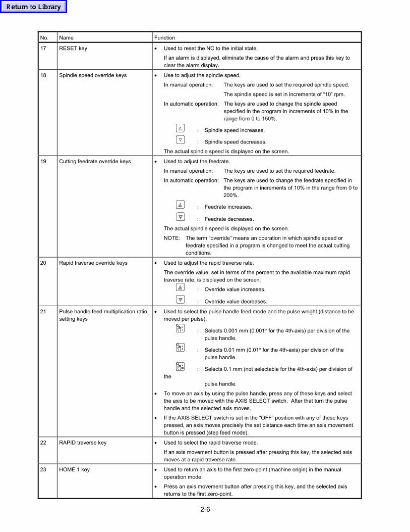
2-6
No. Name Function
17 RESET key • Used to reset the NC to the initial state.
If an alarm is displayed, eliminate the cause of the alarm and press this key toclear the alarm display.
18 Spindle speed override keys • Use to adjust the spindle speed.
In manual operation: The keys are used to set the required spindle speed.
The spindle speed is set in increments of “10” rpm.
In automatic operation: The keys are used to change the spindle speedspecified in the program in increments of 10% in therange from 0 to 150%.
: Spindle speed increases.
: Spindle speed decreases.
The actual spindle speed is displayed on the screen.
19 Cutting feedrate override keys • Used to adjust the feedrate.
In manual operation: The keys are used to set the required feedrate.
In automatic operation: The keys are used to change the feedrate specified inthe program in increments of 10% in the range from 0 to200%.
: Feedrate increases.
: Feedrate decreases.
The actual spindle speed is displayed on the screen.
NOTE: The term “override” means an operation in which spindle speed or feedrate specified in a program is changed to meet the actual cutting conditions.
20 Rapid traverse override keys • Used to adjust the rapid traverse rate.
The override value, set in terms of the percent to the available maximum rapidtraverse rate, is displayed on the screen.
: Override value increases.
: Override value decreases.
21 Pulse handle feed multiplication ratiosetting keys
• Used to select the pulse handle feed mode and the pulse weight (distance to bemoved per pulse).
: Selects 0.001 mm (0.001° for the 4th-axis) per division of thepulse handle.
: Selects 0.01 mm (0.01° for the 4th-axis) per division of thepulse handle.
: Selects 0.1 mm (not selectable for the 4th-axis) per division ofthe
pulse handle.
• To move an axis by using the pulse handle, press any of these keys and selectthe axis to be moved with the AXIS SELECT switch. After that turn the pulsehandle and the selected axis moves.
• If the AXIS SELECT switch is set in the “OFF” position with any of these keyspressed, an axis moves precisely the set distance each time an axis movementbutton is pressed (step feed mode).
22 RAPID traverse key • Used to select the rapid traverse mode.
If an axis movement button is pressed after pressing this key, the selected axismoves at a rapid traverse rate.
23 HOME 1 key • Used to return an axis to the first zero-point (machine origin) in the manualoperation mode.
• Press an axis movement button after pressing this key, and the selected axisreturns to the first zero-point.
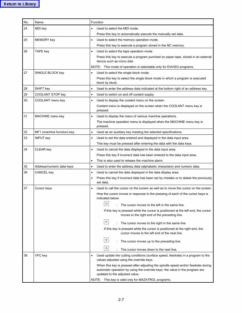
2-7
No. Name Function
24 MDI key • Used to select the MDI mode.
Press this key to automatically execute the manually set data.
25 MEMORY key • Used to select the memory operation mode.
Press this key to execute a program stored in the NC memory.
26 TAPE key • Used to select the tape operation mode.
Press this key to execute a program punched on paper tape, stored in an externaldevice such as micro disk.
NOTE: This mode of operation is selectable only for EIA/ISO programs.
27 SINGLE BLOCK key • Used to select the single block mode.
Press this key to select the single block mode in which a program is executedblock by block.
28 SHIFT key • Used to enter the address data indicated at the bottom right of an address key.
29 COOLANT STOP key • Used to switch on and off coolant supply.
30 COOLANT menu key • Used to display the coolant menu on the screen.
Coolant menu is displayed on the screen when the COOLANT menu key ispressed.
31 MACHINE menu key • Used to display the menu of various machine operations.
The machine operation menu is displayed when the MACHINE menu key ispressed.
32 MF1 (machine function) key • Used as an auxiliary key meeting the selected specifications.
33 INPUT key • Used to set the data entered and displayed in the data input area.
This key must be pressed after entering the data with the data keys.
34 CLEAR key • Used to cancel the data displayed in the data input area.
Press this key if incorrect data has been entered to the data input area.
• This is also used to release the machine alarm.
35 Address/numeric data keys • Used to enter the address data (alphabetic characters) and numeric data.
36 CANCEL key • Used to cancel the data displayed in the data display area.
• Press this key if incorrect data has been set by mistake or to delete the previouslyset data.
37 Cursor keys • Used to call the cursor on the screen as well as to move the cursor on the screen.
How the cursor moves in response to the pressing of each of the cursor keys isindicated below:
: The cursor moves to the left in the same line.
If this key is pressed while the cursor is positioned at the left end, the cursormoves to the right end of the preceding line.
: The cursor moves to the right in the same line.
If this key is pressed while the cursor is positioned at the right end, thecursor moves to the left end of the next line.
: The cursor moves up to the preceding line.
: The cursor moves down to the next line.
38 VFC key • Used update the cutting conditions (surface speed, feedrate) in a program to thevalues adjusted using the override keys.
When this key is pressed after adjusting the spindle speed and/or feedrate duringautomatic operation by using the override keys, the value in the program areupdated to the adjusted value.
NOTE: This key is valid only for MAZATROL programs.
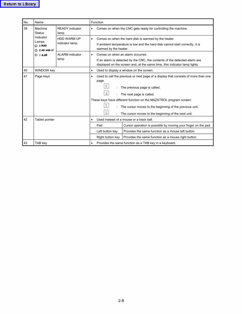
2-8
No. Name Function
READY indicatorlamp
• Comes on when the CNC gets ready for controlling the machine.
HDD WARM UPindicator lamp
• Comes on when the hard disk is warmed by the heater.
If ambient temperature is low and the hard disk cannot start correctly, it iswarmed by the heater.
39 MachineStatusIndicatorLamps
ALARM indicatorlamp
• Comes on when an alarm occurred.
If an alarm is detected by the CNC, the contents of the detected alarm aredisplayed on the screen and, at the same time, this indicator lamp lights.
40 WINDOW key • Used to display a window on the screen.
41 Page keys • Used to call the previous or next page of a display that consists of more than onepage.
: The previous page is called.
: The next page is called.
These keys have different function on the MAZATROL program screen:
: The cursor moves to the beginning of the previous unit.
: The cursor moves to the beginning of the next unit.
• Used instead of a mouse or a track ball.
Pad Cursor operation is possible by moving your finger on the pad.
Left button key Provides the same function as a mouse left button.
42 Tablet pointer
Right button key Provides the same function as a mouse right button.
43 TAB key • Provides the same function as a TAB key in a keyboard.
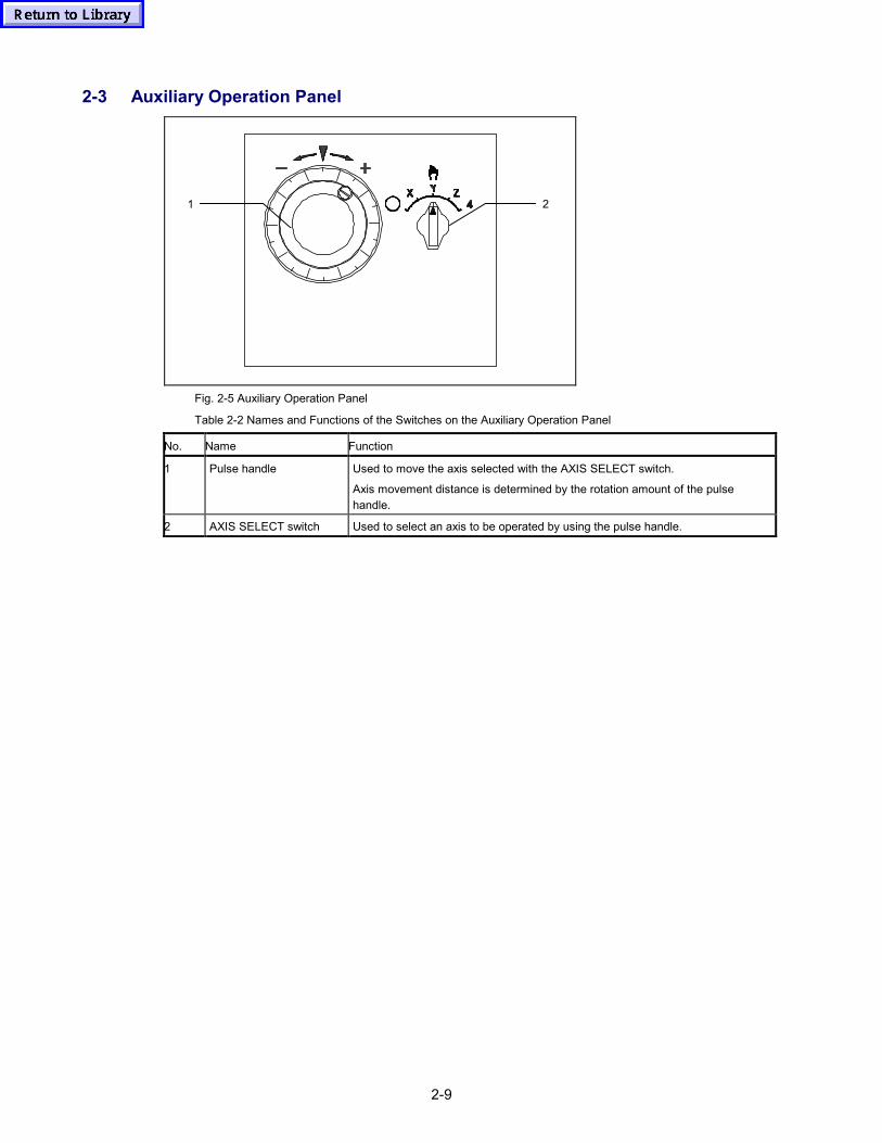
2-9
2-3 Auxiliary Operation Panel
1 2
Fig. 2-5 Auxiliary Operation Panel
Table 2-2 Names and Functions of the Switches on the Auxiliary Operation Panel
No. Name Function
1 Pulse handle Used to move the axis selected with the AXIS SELECT switch.
Axis movement distance is determined by the rotation amount of the pulsehandle.
2 AXIS SELECT switch Used to select an axis to be operated by using the pulse handle.
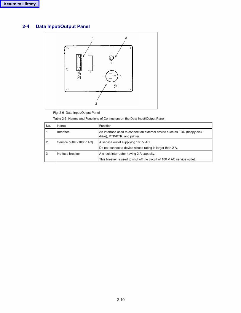
2-10
2-4 Data Input/Output Panel
1
2
3
Fig. 2-6 Data Input/Output Panel
Table 2-3 Names and Functions of Connectors on the Data Input/Output Panel
No. Name Function
1 Interface An interface used to connect an external device such as FDD (floppy diskdrive), PTP/PTR, and printer.
2 Service outlet (100 V AC) A service outlet supplying 100 V AC.
Do not connect a device whose rating is larger than 2 A.
3 No-fuse breaker A circuit interrupter having 2 A capacity.
This breaker is used to shut off the circuit of 100 V AC service outlet.
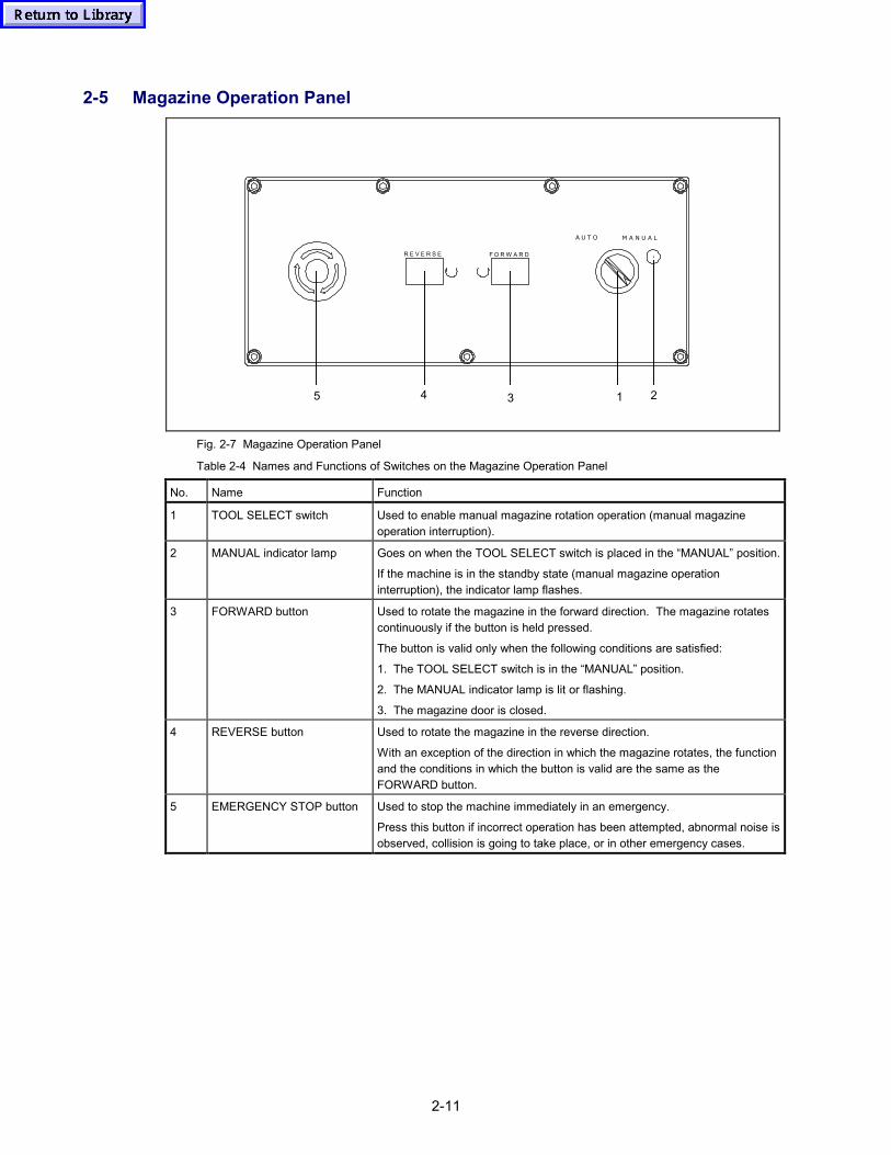
2-11
2-5 Magazine Operation Panel
21345
R E V E R S E F O R W A R D
A U T O M A N U A L
Fig. 2-7 Magazine Operation Panel
Table 2-4 Names and Functions of Switches on the Magazine Operation Panel
No. Name Function
1 TOOL SELECT switch Used to enable manual magazine rotation operation (manual magazineoperation interruption).
2 MANUAL indicator lamp Goes on when the TOOL SELECT switch is placed in the “MANUAL” position.
If the machine is in the standby state (manual magazine operationinterruption), the indicator lamp flashes.
3 FORWARD button Used to rotate the magazine in the forward direction. The magazine rotatescontinuously if the button is held pressed.
The button is valid only when the following conditions are satisfied:
1. The TOOL SELECT switch is in the “MANUAL” position.
2. The MANUAL indicator lamp is lit or flashing.
3. The magazine door is closed.
4 REVERSE button Used to rotate the magazine in the reverse direction.
With an exception of the direction in which the magazine rotates, the functionand the conditions in which the button is valid are the same as theFORWARD button.
5 EMERGENCY STOP button Used to stop the machine immediately in an emergency.
Press this button if incorrect operation has been attempted, abnormal noise isobserved, collision is going to take place, or in other emergency cases.
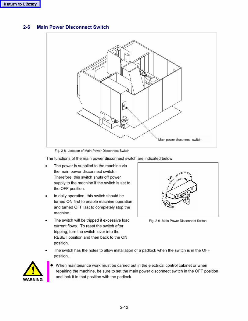
2-12
2-6 Main Power Disconnect Switch
Main power disconnect switch
Fig. 2-8 Location of Main Power Disconnect Switch
The functions of the main power disconnect switch are indicated below.
• The power is supplied to the machine viathe main power disconnect switch.Therefore, this switch shuts off powersupply to the machine if the switch is set tothe OFF position.
• In daily operation, this switch should beturned ON first to enable machine operationand turned OFF last to completely stop themachine.
• The switch will be tripped if excessive loadcurrent flows. To reset the switch aftertripping, turn the switch lever into theRESET position and then back to the ONposition.
Fig. 2-9 Main Power Disconnect Switch
• The switch has the holes to allow installation of a padlock when the switch is in the OFFposition.
WARNING
� When maintenance work must be carried out in the electrical control cabinet or whenrepairing the machine, be sure to set the main power disconnect switch in the OFF positionand lock it in that position with the padlock
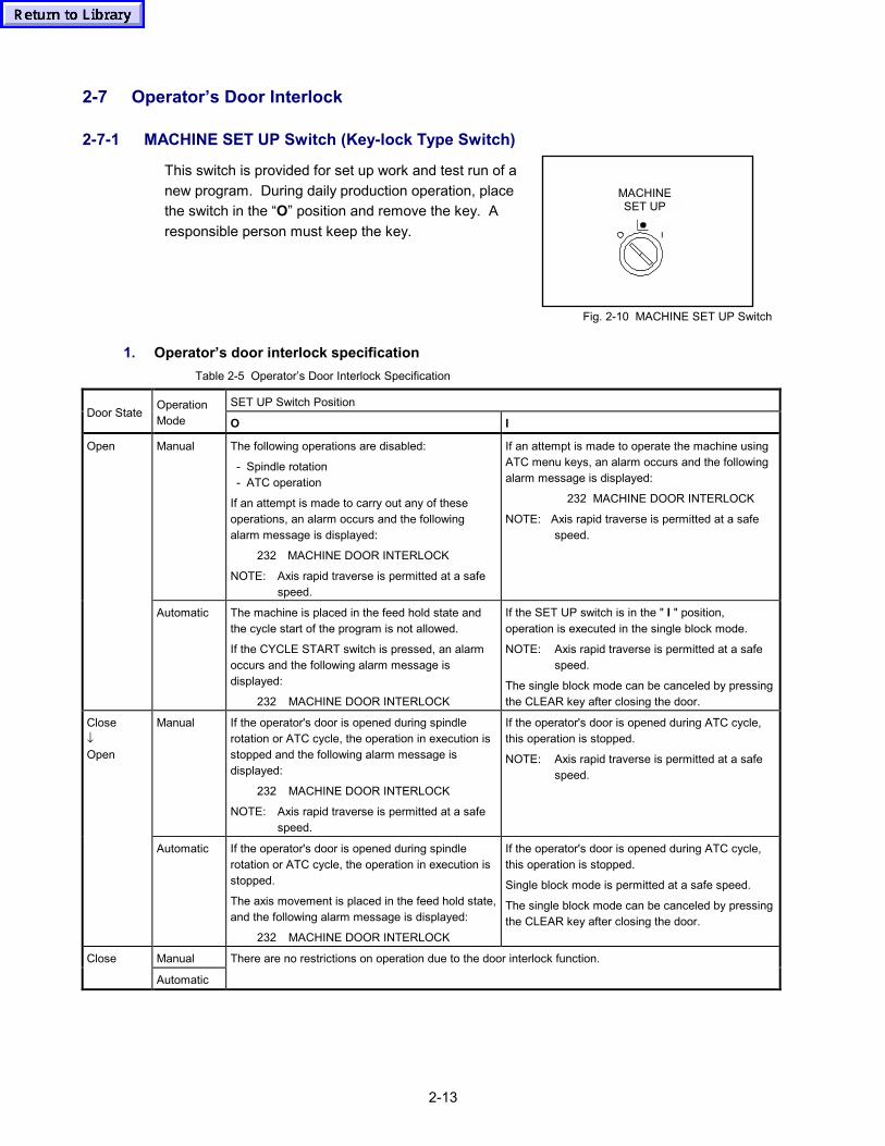
2-13
2-7 Operator’s Door Interlock
2-7-1 MACHINE SET UP Switch (Key-lock Type Switch)
This switch is provided for set up work and test run of anew program. During daily production operation, placethe switch in the “O” position and remove the key. Aresponsible person must keep the key.
MACHINE SET UP
Fig. 2-10 MACHINE SET UP Switch
1. Operator’s door interlock specification Table 2-5 Operator’s Door Interlock Specification
SET UP Switch PositionDoor State
OperationMode O I
Manual The following operations are disabled:
- Spindle rotation- ATC operation
If an attempt is made to carry out any of theseoperations, an alarm occurs and the followingalarm message is displayed:
232 MACHINE DOOR INTERLOCK
NOTE: Axis rapid traverse is permitted at a safespeed.
If an attempt is made to operate the machine usingATC menu keys, an alarm occurs and the followingalarm message is displayed:
232 MACHINE DOOR INTERLOCK
NOTE: Axis rapid traverse is permitted at a safespeed.
Open
Automatic The machine is placed in the feed hold state andthe cycle start of the program is not allowed.
If the CYCLE START switch is pressed, an alarmoccurs and the following alarm message isdisplayed:
232 MACHINE DOOR INTERLOCK
If the SET UP switch is in the " I " position,operation is executed in the single block mode.
NOTE: Axis rapid traverse is permitted at a safespeed.
The single block mode can be canceled by pressingthe CLEAR key after closing the door.
Manual If the operator's door is opened during spindlerotation or ATC cycle, the operation in execution isstopped and the following alarm message isdisplayed:
232 MACHINE DOOR INTERLOCK
NOTE: Axis rapid traverse is permitted at a safespeed.
If the operator's door is opened during ATC cycle,this operation is stopped.
NOTE: Axis rapid traverse is permitted at a safespeed.
Close↓Open
Automatic If the operator's door is opened during spindlerotation or ATC cycle, the operation in execution isstopped.
The axis movement is placed in the feed hold state,and the following alarm message is displayed:
232 MACHINE DOOR INTERLOCK
If the operator's door is opened during ATC cycle,this operation is stopped.
Single block mode is permitted at a safe speed.
The single block mode can be canceled by pressingthe CLEAR key after closing the door.
ManualClose
Automatic
There are no restrictions on operation due to the door interlock function.
2-14
2. Actions to be taken after an occurrence of door interlock function related alarm
To continue the operation after the occurrence of an alarm caused by opening the operator’s door,close the door and clear the alarm message. The procedure to be followed to continue theinterrupted operation is indicated below.
• In automatic mode:Press the cycle start switch.
• In manual mode:Complete the interrupted operation by using the menu key or appropriate operation switch.
If the operation has stopped during ATC cycle, complete the cycle using the procedure indicatedabove.
If it is not necessary to continue the operation after the occurrence of an alarm, simply press thereset key to clear the alarm message.
WARNING
� Before carrying out setup, make sure that the operator’s door is closed.
� In operation while the operator's door is open, pay sufficient care to avoid the following:- To be hit by scattering chips- To be caught or crushed by moving unit- To touch rotating tool
3-1
3 MANUAL OPERATIONThis chapter describes the items to be checked before starting the operation and also manualoperation procedure.
3-1 Inspection before Starting Operation
Refer to Fig. 3-1.
<Procedure>
(1) Check the oil level for the oil tanks indicated below by the oil level gauges. If the oil level islower than the specified level, add the specified oil.
For the procedure used to add the oil, refer to the Maintenance Manual.
• Centralized lubrication unit oil tank
• Hydraulic unit oil tank
• Spindle cooling fluid tank
• Coolant tank
(2) Check that the doors and covers indicated below are securely closed.
• Operator’s door
Close the door so that there is no gap.
• Control panel door
Close the door and secure it in the closed position with the bolt.
• Magazine door
Lock the door with the handle so that the door cannot be opened.
(3) Make sure that all safety covers and safety devices are installed properly. For the safetycovers and safety devices, refer to Part 1, Section 2-9 “Safety Equipment”.
(4) Make sure that the compressed air is supplied to the machine. Also make sure that thepressure gauge at the air inlet port indicates 5 kgf/cm2 (71.1 PSI). If the air pressure is lowerthan 5 kgf/cm2 (71.1 PSI), the air source capacity must be increased. If the air pressure islower than 4 kgf/cm2 (56.9 PSI), never operate the machine since malfunctions will occur.
(5) Make sure that the pressure gauge of the hydraulic unit indicates 0 kgf/cm2 (0 PSI).
If the pressure gauge indication is not 0 kgf/cm2 (0 PSI) while it is stopped, the pressure gaugewill be faulty. In this case, it is necessary to change the pressure gauge. For the procedure ofchanging the pressure gauge, refer to the Maintenance Manual supplied separately.
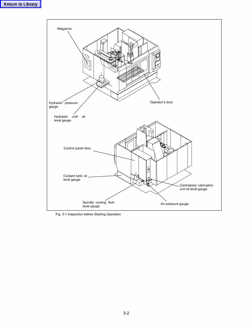
3-2
Hydraulic until oillevel gauge
Hydraulic pressuregauge
Magazine
Operator’s door
Air pressure gauge
Centralized lubricationunit oil level gauge
Spindle cooling fluidlevel gauge
Coolant tank oillevel gauge
Control panel door
Fig. 3-1 Inspection before Starting Operation
3-3
3-2 Switching the Power ON
DANGER
� Cables or wires with damaged insulation could cause current leakage or electrical shocks.Always check that the insulation is sound.
� There are high voltage terminals in the electrical control cabinet, transformers, motors,relay boxes, etc. Never touch these terminals.
� Do not touch the switches with wet hands.
WARNING
� In order to prevent the entry of water, oil, chips, dust, and other foreign matter into theelectrical control cabinet and other machine units, make sure to close the doors and coversof the CNC unit and the electrical control cabinet.
CAUTION
� If the instructions on the factory power distribution board are given on such as a safetyplate, follow these instructions.
<Procedure>
(1) Switch the power ON at the factory power distribution board.
(2) Turn the main power disconnect to the ON position.
→ The fan starts rotating and the (POWER ON) button on the NC operation panellights.
(3) Press the (POWER ON) button on the NC operation panel.
→ The indicator lamp in the (POWER ON) button goes off.
→ The READY lamp, which indicates that the machine is ready for operation, lights.
→ The POSITION display is given.
→ The (first zero-point return) key lights and the following message is displayed.ZERO RETURN
* For the machine equipped with the absolute position detection specification (option), the
(memory operation) key lights.
→ The hydraulic unit pump and the centralized lubrication unit pump start.
3-4
If an abnormality is found when the hydraulic unit starts, press the (POWER OFF) button or theemergency stop button. The hydraulic unit stops operating.
If the “EMERGENCY STOP” message is displayed in red at the lower left area of the POSITIONscreen when the power is switched on, it indicates that one of the emergency stop buttons is lockedin the activated position. In this case, clear the emergency stop status and unlock the emergencystop button.
To reset the emergency stop button, turn the emergency stop button in the direction indicated by thearrow symbols given in it. When it is turned approximately 90 degrees, the button comes out to beunlocked.
After that press the (RESET) key on the NC operation panel, and the red “EMERGENCYSTOP” message is cleared. The hydraulic unit starts operating again.
Note: Before switching on the power for the first time after installation, carry out the inspectionthat is indicated in the Maintenance Manual.
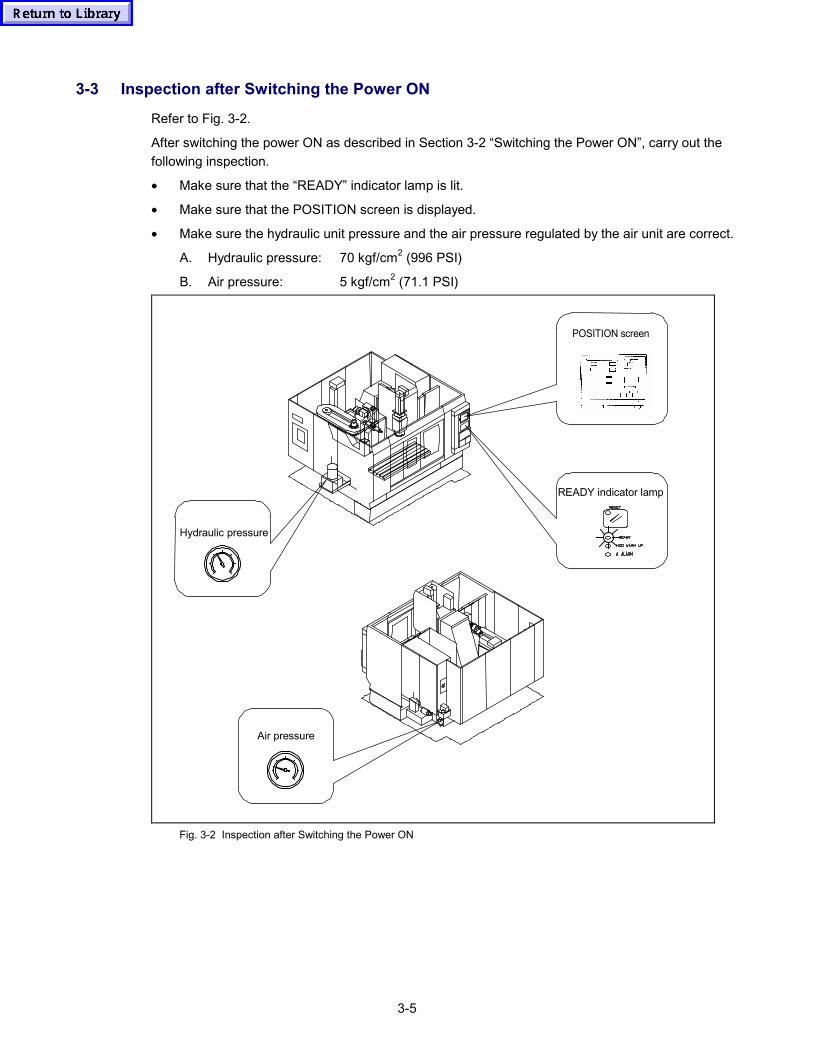
3-5
3-3 Inspection after Switching the Power ON
Refer to Fig. 3-2.
After switching the power ON as described in Section 3-2 “Switching the Power ON”, carry out thefollowing inspection.
• Make sure that the “READY” indicator lamp is lit.
• Make sure that the POSITION screen is displayed.
• Make sure the hydraulic unit pressure and the air pressure regulated by the air unit are correct.
A. Hydraulic pressure: 70 kgf/cm2 (996 PSI)
B. Air pressure: 5 kgf/cm2 (71.1 PSI)
POSITION screen
READY indicator lamp
Hydraulic pressure
Air pressure
Fig. 3-2 Inspection after Switching the Power ON
3-6
3-4 Switching the Power OFF
After finishing day’s operation, follow the procedure indicated below to shut off the power.
DANGER
� There are high voltage terminals in the electrical control cabinet transformers, motors,relay boxes, etc. Never touch these terminals.
� Do not touch the switches with wet hands.
<Procedure>
(1) Make sure that all machine operations (program operation, input/output with external devices,etc.) have been completed.
(2) Press the (POWER OFF) button on the NC operation panel.
→ The indicator lamp in the (POWER ON) button lights.
(3) Turn the main disconnect to the OFF position after the screen display has been turned offcompletely.
Note: If the main disconnect is turned OFF before the screen display is completely turned off,correct NC functions cannot be guaranteed. It will take about one minute before thescreen display is turned off completely.
(4) Shut off the power at the factory power distribution board.
* If the machine is equipped with the automatic power off function (option), refer to the manualprepared separately for the option specifications.
3-7
3-5 Zero-Point Return
After switching on the power, it is necessary to carry out the zero-point return operation first toregister the machine zero point to the NC.
The stored machine zero point is lost when the power is switched off.
Carry out zero-point return operation for all axes (X-, Y-, Z-, and 4th-axis (option)) to the first zeropoint.
WARNING
� Do not press the switches while wearing gloves. This could cause machining malfunctionand other troubles.
� To prevent machine malfunction, confirm the function of the switches before using them.
CAUTION
� With the machine equipped with the optional absolute position detection function, themachine zero-point data is not lost even when the power is switched off. Accordingly, it isnot necessary to carry out the zero-point return operation.
� If battery voltage is lowered, the machine zero-point data may be lost. If the “ZERORETURN” message is displayed, the machine zero-point data is lost. In this case, carryout the zero-point return operation.
The “ZERO RETURN” message is displayed in green at the lower right area of the POSITIONscreen when the power is switched on. Carry out the zero-point return operation for the X-, Y-, Z-and 4th-axis (option) by pressing the axis movement button on the NC operation panel.
The procedure for the first zero-point return is indicated below.
<Procedure>
(1) Press the (first zero-point return) key.Note that immediately after the power is switched on, the key is in the pressed state. Thegreen lamp lights to indicate that the key has been pressed.
(2) If an axis is close to the zero-point, first momentarily press the -X, -Y, -Z or -4th (optional) keycorresponding the axis to be returned to the zero-point.
→ The axis moves in the negative direction and then moves in the positive direction to thezero-point. On completion of the zero-point return cycle, the green zero-point returnindicator lamp on the NC operation panel will light. Refer to Fig. 2-3.
Once an axis starts moving in the positive direction, the axis will continue moving to thezero-point even if the axis movement key is released. The axis moves to the zero-point atthe zero-point approach speed (0.2 m/min (11.8 IPM)). Refer to Fig. 3-3.
(3) If an axis is not close to the zero-point, momentarily press the -X, -Y, -Z or -4th (optional) keycorresponding the axis to be returned to the zero-point first. Next, hold the +X, +Y, +Z, or +4th(optional) key corresponding the axis to be returned to the zero-point pressed. Refer to Fig. 2-3.
• The axis will stop moving if the key is released.
• The key can be released after the axis feedrate is decelerated to the zero-point approachspeed (0.2 m/min (11.8 IPM)). The axis continues moving to the zero-point even if the keyis released. Refer to Remark 3.
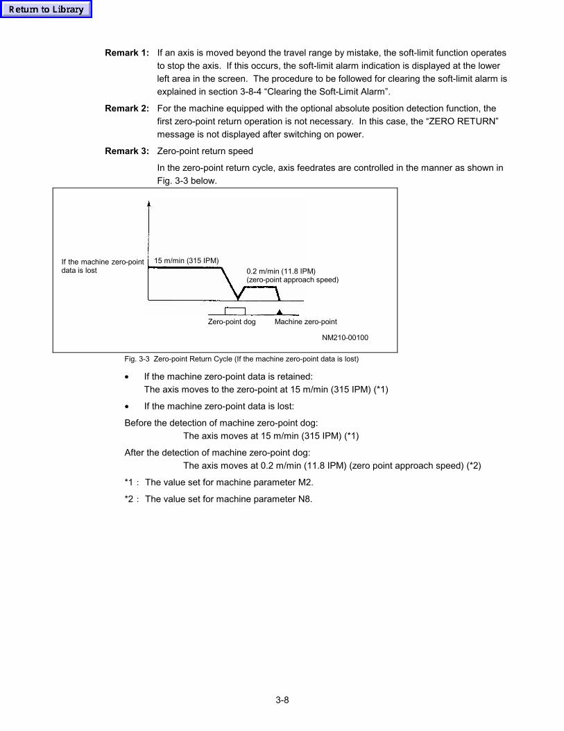
3-8
Remark 1: If an axis is moved beyond the travel range by mistake, the soft-limit function operatesto stop the axis. If this occurs, the soft-limit alarm indication is displayed at the lowerleft area in the screen. The procedure to be followed for clearing the soft-limit alarm isexplained in section 3-8-4 “Clearing the Soft-Limit Alarm”.
Remark 2: For the machine equipped with the optional absolute position detection function, thefirst zero-point return operation is not necessary. In this case, the “ZERO RETURN”message is not displayed after switching on power.
Remark 3: Zero-point return speed
In the zero-point return cycle, axis feedrates are controlled in the manner as shown inFig. 3-3 below.
If the machine zero-pointdata is lost
Zero-point dog Machine zero-point
15 m/min (315 IPM)0.2 m/min (11.8 IPM)(zero-point approach speed)
NM210-00100
Fig. 3-3 Zero-point Return Cycle (If the machine zero-point data is lost)
• If the machine zero-point data is retained:The axis moves to the zero-point at 15 m/min (315 IPM) (*1)
• If the machine zero-point data is lost:
Before the detection of machine zero-point dog:The axis moves at 15 m/min (315 IPM) (*1)
After the detection of machine zero-point dog:The axis moves at 0.2 m/min (11.8 IPM) (zero point approach speed) (*2)
*1: The value set for machine parameter M2.
*2: The value set for machine parameter N8.
3-9
3-6 Warmup Operation
When starting the machine operation after it has been stopped for a long period, it is necessary towarm up the machine in the schedule as indicated below.
Since the machine has not been operated for a long period, the slideways are not lubricatedappropriately which will cause stick-slip in axis movement as well as abnormal wear of the slidewaysif production is started immediately. In addition, thermal expansion must be taken intoconsideration. At the beginning of machine operation, thermal expansion is not stabilized and thusworkpieces machined during such period cannot be finished accurately.
By conducting warm up, the slideways can be appropriately lubricated to ensure smooth andaccurate axis movement. It also stabilizes the machine from the viewpoint of thermal expansion togive consistently high accuracy.
Warm up must be conducted before starting daily operation to produce accurate products from thefirst output. In cold areas, warm must be conducted sufficiently.
Recommended warm up schedule
Warm up period Approx. 30 minutes
Spindle speed 1000 min–1 (rpm) → 3000 min–1 (rpm) → 8000 min–1 (rpm) → Max. speed
Axis stroke range Entire axis stroke
CAUTION
� While carrying out warm up, observe the machine operating status, lubrication, and others.
3-10
3-7 Spindle Operation
This section describes the procedure used for starting and stopping the spindle and also theprocedure for changing the spindle rotating direction.
3-7-1 Starting the Spindle
To start the spindle when carrying out simple machining operation, follow the steps indicated below.
<Procedure>
(1) Press one of manual operation mode selector keys.
(2) Adjust the spindle speed by using the spindle override keys.
• The spindle speed can be adjusted in the range from 0 to maximum spindle speed inincrements of 10 min–1 (rpm).
: Spindle speed increases.
: Spindle speed decreases.
• Spindle speed is displayed in units of 10 min–1 (rpm).
• The set spindle speed is displayed below the menu on the NC screen.
(3) Press the (SPINDLE START) button.
→ The spindle starts rotating.
While the spindle is rotating, the indicator lamp in the button remains lit.
3-7-2 Stopping the Spindle
To stop the spindle, follow the step indicated below.
(1) Press the (SPINDLE STOP) button.
→ The spindle stops rotating.
Note 1: The spindle speed displayed below the menu on the NC screen remains unchanged evenwhen the spindle stops rotating.
Note 2: The spindle does not stop rotating even if the SPINDLE STOP button is pressed while inautomatic operation.
3-7-3 Jogging the Spindle
To jog the spindle for such as checking the tool mounting conditions in the spindle or measuring thetool nose position, follow the steps indicated below.
<Procedure>
(1) Press one of the manual operation mode selector keys.
(2) Select the POSITION screen and press the [SPDL JOG] menu key.
→ The spindle jogs while the button is held pressed, and stops jogging when the key isreleased.
• Spindle jog speed is 50 min–1 (rpm).
3-11
3-7-4 Changing the Direction of Spindle Rotation
To change the direction of spindle rotation, follow the step indicated below.
(1) Select the spindle rotation direction by pressing the [SPNDL REV] menu key on the POSITIONscreen.
• The lamp in the menu is lit: The spindle rotates in the forward direction.
• The lamp in the menu is unlit: The spindle rotates in the reverse direction.
3-8 Feed Operation
3-8-1 Rapid Traverse Operation
To move an axis at a rapid traverse rate for such as mounting a tool to the spindle or carrying outpositioning, follow the steps indicated below.
(1) Press the (RAPID) key.
→ The rapid traverse mode is selected.
(2) Adjust the rapid traverse rate.
It is possible to adjust the rapid traverse rate with the rapid traverse override keys in the range from6% to 100% of the maximum traverse rate 100%, 50%, 25%, 12%, 6%
The values of 25%, 12%, and 6% are set for parameters and can be changed if required.
: The rapid traverse rate increases by one step.
: The rapid traverse rate decreases by one step.
(3) Move an axis to the required position by pressing the axis movement button.
• The axis is continuously moved while the axis movement button is held pressed and itstops moving when the button is released.
• The actual axis position is displayed on the NC screen such as the POSITION display.
3-8-2 Cutting Feed Operation
To move an axis at a controlled feedrate to carry out simple cutting, follow the steps indicatedbelow.
(1) Select any of the (pulse handle feed multiplication ratio setting) keys.
(2) Place the AXIS SELECT switch in the required axis position. (See Fig. 2-5.)
→ The jog (cutting feed) mode is selected.
(3) Adjust the feedrate.
• It is possible to adjust the feedrate in 29 steps of preset feedrate in the range from 0 to2000 mm/min (0 to 78.74 IPM) by using the cutting feedrate override keys.
: The feedrate increases by one step.
: The feedrate decreases by one step.
• The actual feedrate is displayed below the menu on the NC screen.
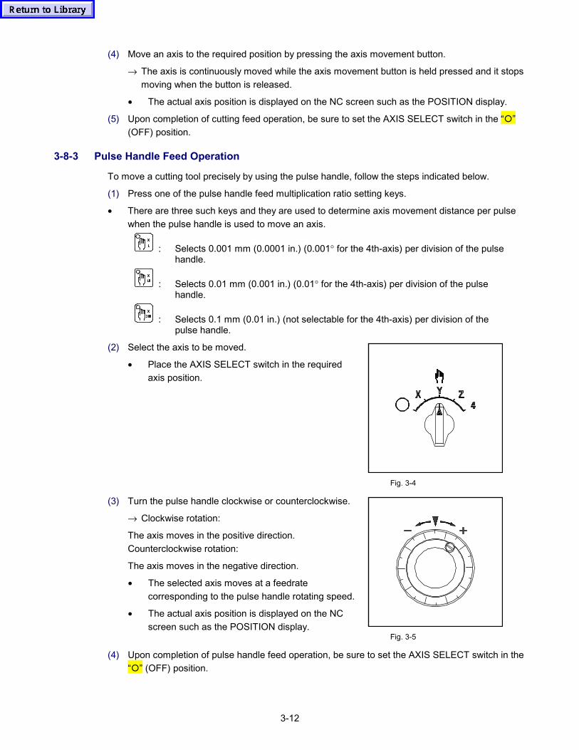
3-12
(4) Move an axis to the required position by pressing the axis movement button.
→ The axis is continuously moved while the axis movement button is held pressed and it stopsmoving when the button is released.
• The actual axis position is displayed on the NC screen such as the POSITION display.
(5) Upon completion of cutting feed operation, be sure to set the AXIS SELECT switch in the “�”(OFF) position.
3-8-3 Pulse Handle Feed Operation
To move a cutting tool precisely by using the pulse handle, follow the steps indicated below.
(1) Press one of the pulse handle feed multiplication ratio setting keys.
• There are three such keys and they are used to determine axis movement distance per pulsewhen the pulse handle is used to move an axis.
: Selects 0.001 mm (0.0001 in.) (0.001° for the 4th-axis) per division of the pulsehandle.
: Selects 0.01 mm (0.001 in.) (0.01° for the 4th-axis) per division of the pulsehandle.
: Selects 0.1 mm (0.01 in.) (not selectable for the 4th-axis) per division of thepulse handle.
(2) Select the axis to be moved.
• Place the AXIS SELECT switch in the requiredaxis position.
Fig. 3-4
(3) Turn the pulse handle clockwise or counterclockwise.
→ Clockwise rotation:
The axis moves in the positive direction.Counterclockwise rotation:
The axis moves in the negative direction.
• The selected axis moves at a feedratecorresponding to the pulse handle rotating speed.
• The actual axis position is displayed on the NCscreen such as the POSITION display.
Fig. 3-5
(4) Upon completion of pulse handle feed operation, be sure to set the AXIS SELECT switch in the“�” (OFF) position.
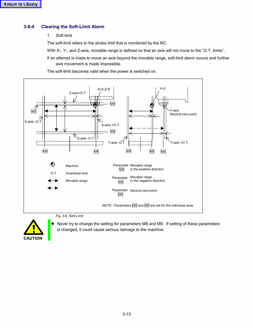
3-13
3-8-4 Clearing the Soft-Limit Alarm
1. Soft-limit
The soft-limit refers to the stroke limit that is monitored by the NC.
With X-, Y-, and Z-axis, movable range is defined so that an axis will not move to the “O.T. limits”.
If an attempt is made to move an axis beyond the movable range, soft-limit alarm occurs and furtheraxis movement is made impossible.
The soft-limit becomes valid when the power is switched on.
X-axis +O.T.X-axis -O.T.
X=0,Z=0 Y=0
Y-axis -O.T Y-axis +O.T.
Y-axisSecond zero-point
Z-axis+O.T
Z-axis -O.T.
M8
M9
M8M9 M8M9 M5
O.T
Machine
Overtravel limit
Movable range
ParameterM8
ParameterM9
Movable rangein the positive direction
Movable rangein the negative direction
ParameterM5
Second zero-point
NOTE : Parameters M8 and M9 are set for the individual axes
M5
Fig. 3-6 Soft-Limit
CAUTION
� Never try to change the setting for parameters M8 and M9. If setting of these parametersis changed, it could cause serious damage to the machine.
3-14
2. Cleaning the soft-limit alarm
If an axis fails to move continuously due to the occurrence of a soft-limit alarm, move the axisin the opposite direction.
Example: Soft-limit alarm has occurred during axis feed of the X-axis in the positive directionby using the pulse handle.
(1) An axis does not move even when the pulse handle is rotated in the +X direction.
The following alarm message is displayed at the lower left area in the screen.
101 SOFT LIMIT +X
(2) Turn the pulse handle in the -X direction.
(3) The axis starts moving in the -X direction and the alarm message indicated above iscleared.
(4) This completes the restoration from the soft-limit alarm state.
It is possible to clear the soft-limit alarm in the following operation modes.
: Manual pulse feed mode (includes cutting feed)
: Rapid traverse mode
: Zero-point return mode (includes second zero-point return)
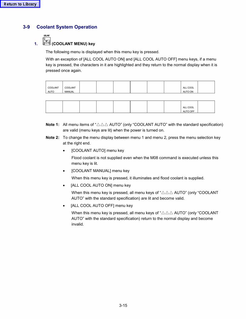
3-15
3-9 Coolant System Operation
1. (COOLANT MENU) key
The following menu is displayed when this menu key is pressed.
With an exception of [ALL COOL AUTO ON] and [ALL COOL AUTO OFF] menu keys, if a menukey is pressed, the characters in it are highlighted and they return to the normal display when it ispressed once again.
COOLANTAUTO
COOLANTMANUAL
ALL COOLAUTO ON
ALL COOLAUTO OFF
Note 1: All menu items of “△△△ AUTO” (only “COOLANT AUTO” with the standard specification)are valid (menu keys are lit) when the power is turned on.
Note 2: To change the menu display between menu 1 and menu 2, press the menu selection keyat the right end.
• [COOLANT AUTO] menu key
Flood coolant is not supplied even when the M08 command is executed unless thismenu key is lit.
• [COOLANT MANUAL] menu key
When this menu key is pressed, it illuminates and flood coolant is supplied.
• [ALL COOL AUTO ON] menu key
When this menu key is pressed, all menu keys of “△△△ AUTO” (only “COOLANTAUTO” with the standard specification) are lit and become valid.
• [ALL COOL AUTO OFF] menu key
When this menu key is pressed, all menu keys of “△△△ AUTO” (only “COOLANTAUTO” with the standard specification) return to the normal display and becomeinvalid.
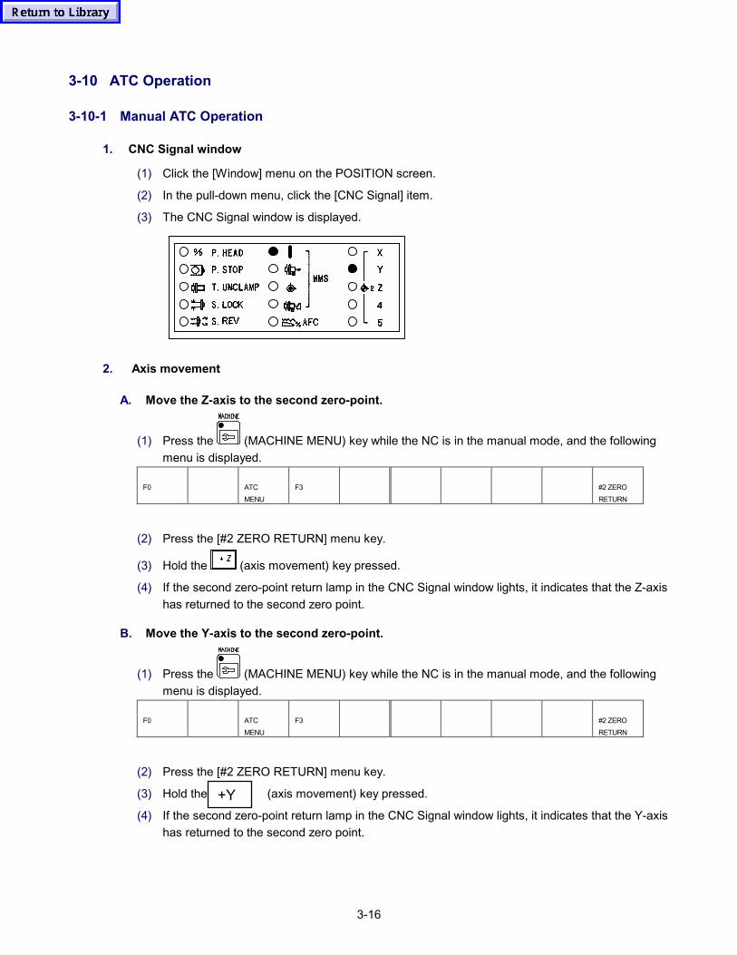
3-16
3-10 ATC Operation
3-10-1 Manual ATC Operation
1. CNC Signal window
(1) Click the [Window] menu on the POSITION screen.
(2) In the pull-down menu, click the [CNC Signal] item.
(3) The CNC Signal window is displayed.
2. Axis movement
A. Move the Z-axis to the second zero-point.
(1) Press the (MACHINE MENU) key while the NC is in the manual mode, and the followingmenu is displayed.
F0 ATCMENU
F3 #2 ZERORETURN
(2) Press the [#2 ZERO RETURN] menu key.
(3) Hold the (axis movement) key pressed.
(4) If the second zero-point return lamp in the CNC Signal window lights, it indicates that the Z-axishas returned to the second zero point.
B. Move the Y-axis to the second zero-point.
(1) Press the (MACHINE MENU) key while the NC is in the manual mode, and the followingmenu is displayed.
F0 ATCMENU
F3 #2 ZERORETURN
(2) Press the [#2 ZERO RETURN] menu key.
(3) Hold the (axis movement) key pressed.
(4) If the second zero-point return lamp in the CNC Signal window lights, it indicates that the Y-axishas returned to the second zero point.
+Y
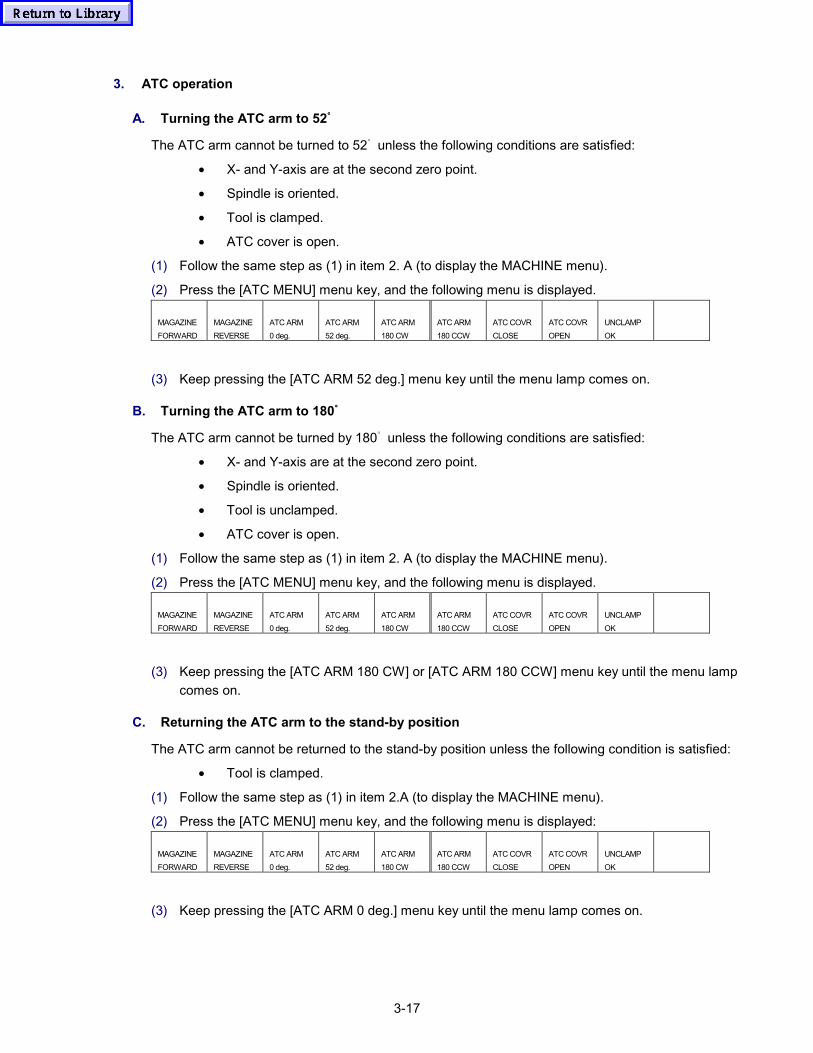
3-17
3. ATC operation
A. Turning the ATC arm to 52゚゚゚゚
The ATC arm cannot be turned to 52゚ unless the following conditions are satisfied:
• X- and Y-axis are at the second zero point.
• Spindle is oriented.
• Tool is clamped.
• ATC cover is open.
(1) Follow the same step as (1) in item 2. A (to display the MACHINE menu).
(2) Press the [ATC MENU] menu key, and the following menu is displayed.
MAGAZINEFORWARD
MAGAZINEREVERSE
ATC ARM0 deg.
ATC ARM52 deg.
ATC ARM180 CW
ATC ARM180 CCW
ATC COVRCLOSE
ATC COVROPEN
UNCLAMPOK
(3) Keep pressing the [ATC ARM 52 deg.] menu key until the menu lamp comes on.
B. Turning the ATC arm to 180゚゚゚゚
The ATC arm cannot be turned by 180゚ unless the following conditions are satisfied:
• X- and Y-axis are at the second zero point.
• Spindle is oriented.
• Tool is unclamped.
• ATC cover is open.
(1) Follow the same step as (1) in item 2. A (to display the MACHINE menu).
(2) Press the [ATC MENU] menu key, and the following menu is displayed.
MAGAZINEFORWARD
MAGAZINEREVERSE
ATC ARM0 deg.
ATC ARM52 deg.
ATC ARM180 CW
ATC ARM180 CCW
ATC COVRCLOSE
ATC COVROPEN
UNCLAMPOK
(3) Keep pressing the [ATC ARM 180 CW] or [ATC ARM 180 CCW] menu key until the menu lampcomes on.
C. Returning the ATC arm to the stand-by position
The ATC arm cannot be returned to the stand-by position unless the following condition is satisfied:
• Tool is clamped.
(1) Follow the same step as (1) in item 2.A (to display the MACHINE menu).
(2) Press the [ATC MENU] menu key, and the following menu is displayed:
MAGAZINEFORWARD
MAGAZINEREVERSE
ATC ARM0 deg.
ATC ARM52 deg.
ATC ARM180 CW
ATC ARM180 CCW
ATC COVRCLOSE
ATC COVROPEN
UNCLAMPOK
(3) Keep pressing the [ATC ARM 0 deg.] menu key until the menu lamp comes on.
3-18
4. Others
A. Perform the ATC cover open operation.
(1) Follow the same steps as (1) and (2) in item 3. A.
(2) Press the [ATC COVR OPEN] menu key.
B. Perform the ATC cover close operation.
(1) Follow the same steps as (1) and (2) in item 3. A.
(2) Press the [ATC COVR CLOSE] menu key.
C. Perform the magazine forward rotation.
(1) Follow the same steps as (1) and (2) in item 3.A.
(2) Press the [MAGAZINE FORWARD] menu key.
D. Perform the magazine reverse rotation.
(1) Follow the same steps as (1) and (2) in item 3.A.
(2) Press the [MAGAZINE REVERSE] menu key.
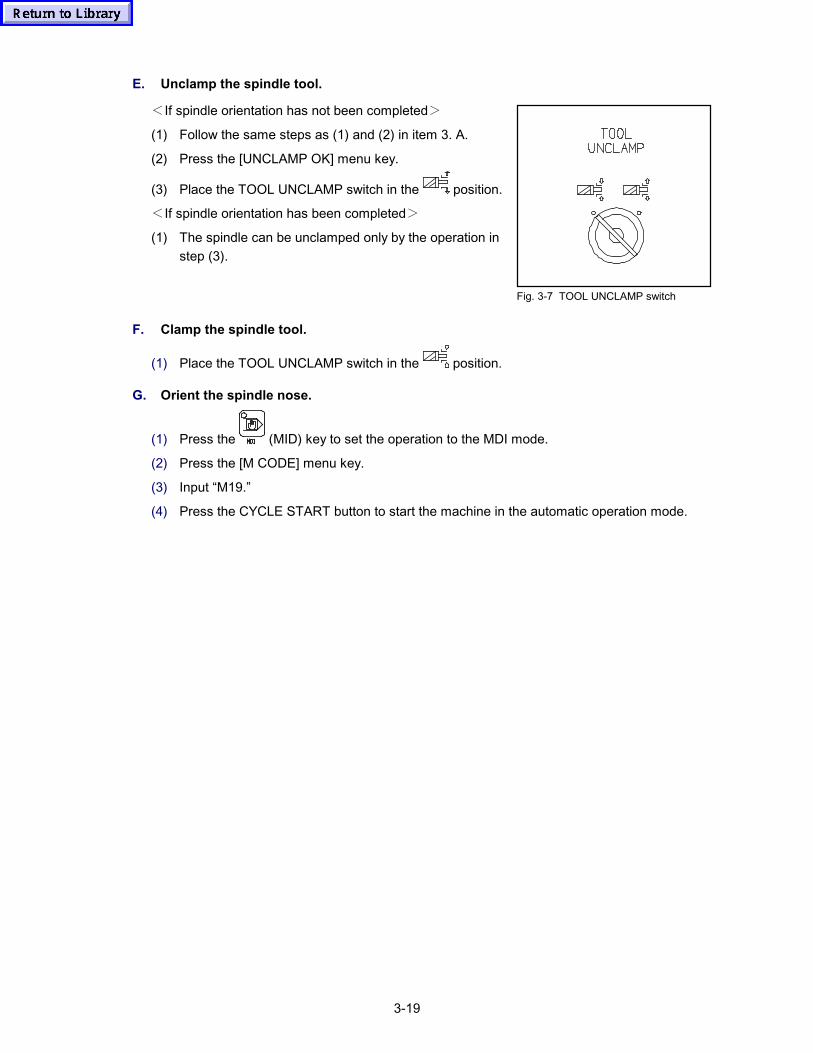
3-19
E. Unclamp the spindle tool.
<If spindle orientation has not been completed>
(1) Follow the same steps as (1) and (2) in item 3. A.
(2) Press the [UNCLAMP OK] menu key.
(3) Place the TOOL UNCLAMP switch in the position.
<If spindle orientation has been completed>
(1) The spindle can be unclamped only by the operation instep (3).
Fig. 3-7 TOOL UNCLAMP switch
F. Clamp the spindle tool.
(1) Place the TOOL UNCLAMP switch in the position.
G. Orient the spindle nose.
(1) Press the (MID) key to set the operation to the MDI mode.
(2) Press the [M CODE] menu key.
(3) Input “M19.”
(4) Press the CYCLE START button to start the machine in the automatic operation mode.
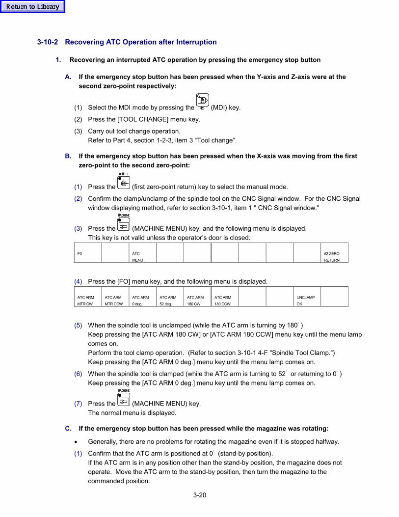
3-20
3-10-2 Recovering ATC Operation after Interruption
1. Recovering an interrupted ATC operation by pressing the emergency stop button
A. If the emergency stop button has been pressed when the Y-axis and Z-axis were at thesecond zero-point respectively:
(1) Select the MDI mode by pressing the (MDI) key.
(2) Press the [TOOL CHANGE] menu key.
(3) Carry out tool change operation.Refer to Part 4, section 1-2-3, item 3 “Tool change”.
B. If the emergency stop button has been pressed when the X-axis was moving from the firstzero-point to the second zero-point:
(1) Press the (first zero-point return) key to select the manual mode.
(2) Confirm the clamp/unclamp of the spindle tool on the CNC Signal window. For the CNC Signalwindow displaying method, refer to section 3-10-1, item 1 " CNC Signal window."
(3) Press the (MACHINE MENU) key, and the following menu is displayed.This key is not valid unless the operator’s door is closed.
F0 ATCMENU
#2 ZERORETURN
(4) Press the [FO] menu key, and the following menu is displayed.
ATC ARMMTR CW
ATC ARMMTR CCW
ATC ARM0 deg.
ATC ARM52 deg.
ATC ARM180 CW
ATC ARM180 CCW
UNCLAMPOK
(5) When the spindle tool is unclamped (while the ATC arm is turning by 180゚)Keep pressing the [ATC ARM 180 CW] or [ATC ARM 180 CCW] menu key until the menu lampcomes on.Perform the tool clamp operation. (Refer to section 3-10-1 4-F "Spindle Tool Clamp.")Keep pressing the [ATC ARM 0 deg.] menu key until the menu lamp comes on.
(6) When the spindle tool is clamped (while the ATC arm is turning to 52゚ or returning to 0゚)Keep pressing the [ATC ARM 0 deg.] menu key until the menu lamp comes on.
(7) Press the (MACHINE MENU) key.The normal menu is displayed.
C. If the emergency stop button has been pressed while the magazine was rotating:
• Generally, there are no problems for rotating the magazine even if it is stopped halfway.
(1) Confirm that the ATC arm is positioned at 0゚ (stand-by position).If the ATC arm is in any position other than the stand-by position, the magazine does notoperate. Move the ATC arm to the stand-by position, then turn the magazine to thecommanded position.
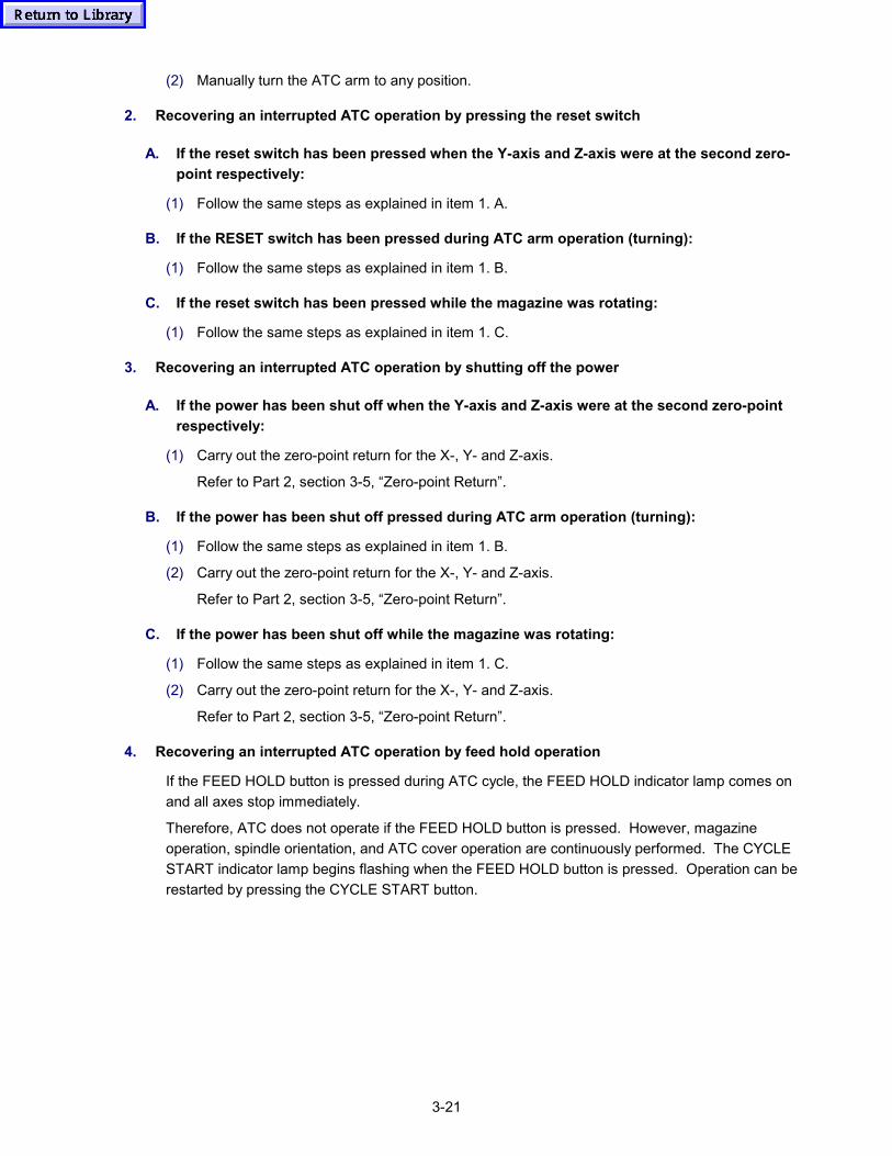
3-21
(2) Manually turn the ATC arm to any position.
2. Recovering an interrupted ATC operation by pressing the reset switch
A. If the reset switch has been pressed when the Y-axis and Z-axis were at the second zero-point respectively:
(1) Follow the same steps as explained in item 1. A.
B. If the RESET switch has been pressed during ATC arm operation (turning):
(1) Follow the same steps as explained in item 1. B.
C. If the reset switch has been pressed while the magazine was rotating:
(1) Follow the same steps as explained in item 1. C.
3. Recovering an interrupted ATC operation by shutting off the power
A. If the power has been shut off when the Y-axis and Z-axis were at the second zero-pointrespectively:
(1) Carry out the zero-point return for the X-, Y- and Z-axis.
Refer to Part 2, section 3-5, “Zero-point Return”.
B. If the power has been shut off pressed during ATC arm operation (turning):
(1) Follow the same steps as explained in item 1. B.
(2) Carry out the zero-point return for the X-, Y- and Z-axis.
Refer to Part 2, section 3-5, “Zero-point Return”.
C. If the power has been shut off while the magazine was rotating:
(1) Follow the same steps as explained in item 1. C.
(2) Carry out the zero-point return for the X-, Y- and Z-axis.
Refer to Part 2, section 3-5, “Zero-point Return”.
4. Recovering an interrupted ATC operation by feed hold operation
If the FEED HOLD button is pressed during ATC cycle, the FEED HOLD indicator lamp comes onand all axes stop immediately.
Therefore, ATC does not operate if the FEED HOLD button is pressed. However, magazineoperation, spindle orientation, and ATC cover operation are continuously performed. The CYCLESTART indicator lamp begins flashing when the FEED HOLD button is pressed. Operation can berestarted by pressing the CYCLE START button.
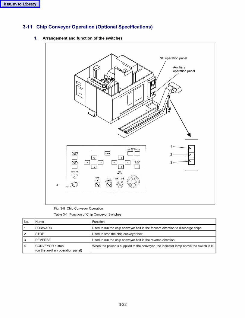
3-22
3-11 Chip Conveyor Operation (Optional Specifications)
1. Arrangement and function of the switches
NC operation panel
Auxiliaryoperation panel
4
2
1
3
Fig. 3-8 Chip Conveyor Operation
Table 3-1 Function of Chip Conveyor Switches
No. Name Function
1 FORWARD Used to run the chip conveyor belt in the forward direction to discharge chips.
2 STOP Used to stop the chip conveyor belt.
3 REVERSE Used to run the chip conveyor belt in the reverse direction.
4 CONVEYOR button(on the auxiliary operation panel)
When the power is supplied to the conveyor, the indicator lamp above the switch is lit.

3-23
2. Operation procedure
CAUTION
� In daily operation, the chip conveyor must be kept operating in the forward directiondisregarding of whether or not chips are being generated.
� If large volume of chips are put into the chip conveyor at a time, chips will be stuck in theconveyor, causing the conveyor to stop.
<Procedure>
(1) Switch the power ON to the machine.
(2) Make sure that the conveyor can be operated safely.
(3) Press the FORWARD switch.
If this occurs, refer to the operating manual supplied with the chip conveyor to recover the chipconveyor operation.

3-24
- MEMO -
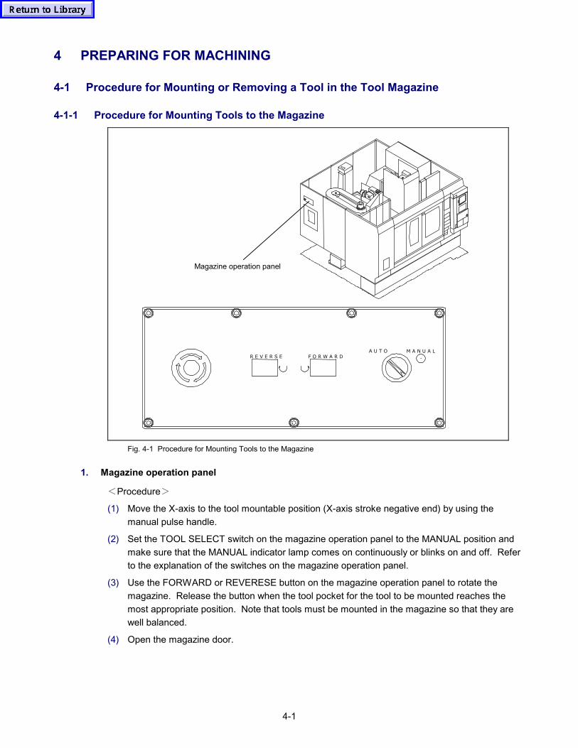
4-1
4 PREPARING FOR MACHINING
4-1 Procedure for Mounting or Removing a Tool in the Tool Magazine
4-1-1 Procedure for Mounting Tools to the Magazine
Magazine operation panel
R E V E R S E F O R W A R DA U T O M A N U A L
Fig. 4-1 Procedure for Mounting Tools to the Magazine
1. Magazine operation panel
<Procedure>
(1) Move the X-axis to the tool mountable position (X-axis stroke negative end) by using themanual pulse handle.
(2) Set the TOOL SELECT switch on the magazine operation panel to the MANUAL position andmake sure that the MANUAL indicator lamp comes on continuously or blinks on and off. Referto the explanation of the switches on the magazine operation panel.
(3) Use the FORWARD or REVERESE button on the magazine operation panel to rotate themagazine. Release the button when the tool pocket for the tool to be mounted reaches themost appropriate position. Note that tools must be mounted in the magazine so that they arewell balanced.
(4) Open the magazine door.
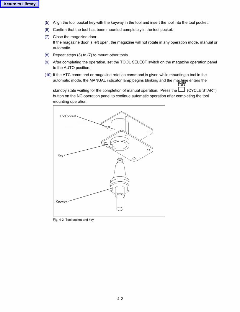
4-2
(5) Align the tool pocket key with the keyway in the tool and insert the tool into the tool pocket.
(6) Confirm that the tool has been mounted completely in the tool pocket.
(7) Close the magazine door.If the magazine door is left open, the magazine will not rotate in any operation mode, manual orautomatic.
(8) Repeat steps (3) to (7) to mount other tools.
(9) After completing the operation, set the TOOL SELECT switch on the magazine operation panelto the AUTO position.
(10) If the ATC command or magazine rotation command is given while mounting a tool in theautomatic mode, the MANUAL indicator lamp begins blinking and the machine enters the
standby state waiting for the completion of manual operation. Press the (CYCLE START)button on the NC operation panel to continue automatic operation after completing the toolmounting operation.
Tool pocket
Key
Keyway
Fig. 4-2 Tool pocket and key
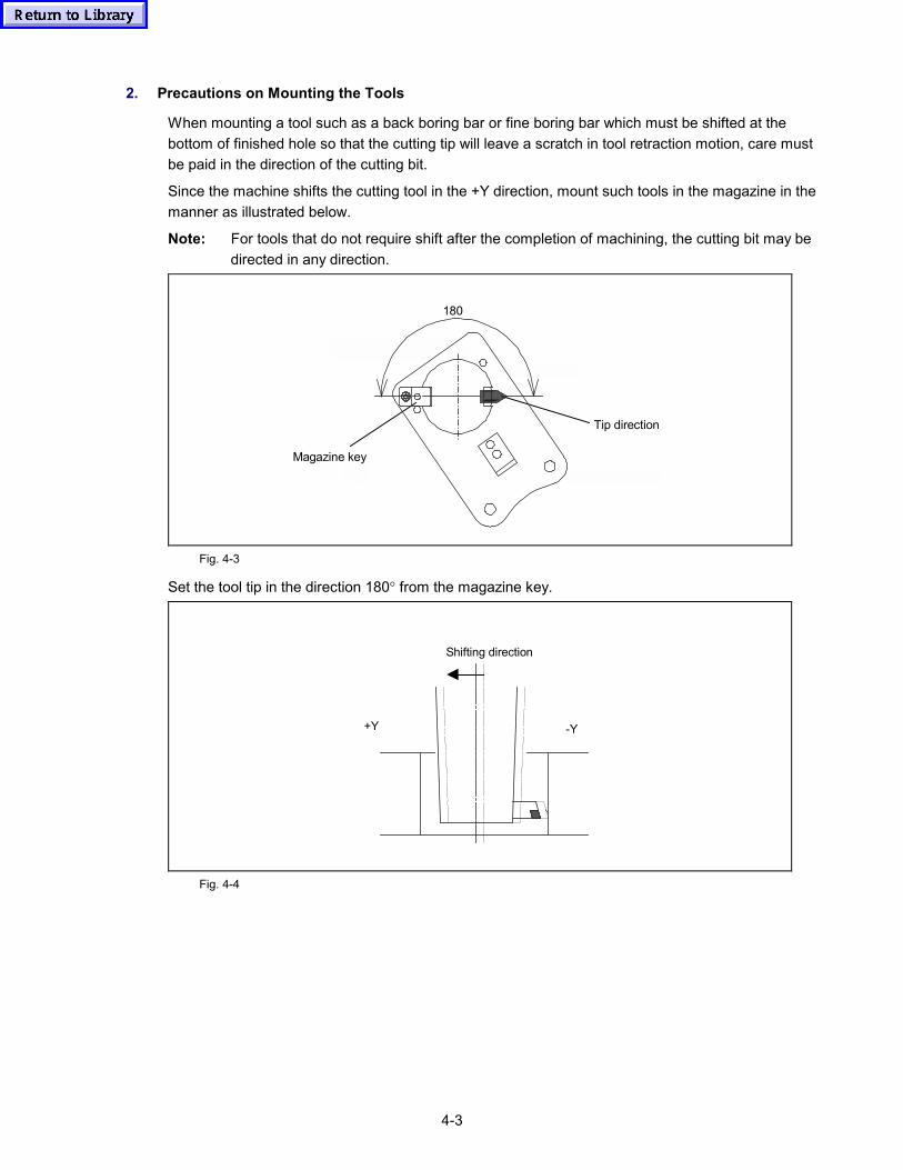
4-3
2. Precautions on Mounting the Tools
When mounting a tool such as a back boring bar or fine boring bar which must be shifted at thebottom of finished hole so that the cutting tip will leave a scratch in tool retraction motion, care mustbe paid in the direction of the cutting bit.
Since the machine shifts the cutting tool in the +Y direction, mount such tools in the magazine in themanner as illustrated below.
Note: For tools that do not require shift after the completion of machining, the cutting bit may bedirected in any direction.
180
Magazine key
Tip direction
Fig. 4-3
Set the tool tip in the direction 180° from the magazine key.
Shifting direction
-Y+Y
Fig. 4-4
4-4
4-1-2 Procedure for Removing Tools from the Magazine
<Procedure>
(1) Tools can be removed from the magazine regardless of whether the NC operation panel is setto the manual or automatic mode.
(2) Set the TOOL SELECT switch on the magazine operation panel to the MANUAL position andmake sure that the MANUAL indicator lamp comes on continuously or blinks on and off. Referto the explanation of the switches on the magazine operation panel.
(3) Use the FORWARD or REVERSE button on the magazine operation panel to rotate themagazine. Release the switch when the tool to be removed reaches the most appropriateposition.
(4) Open the magazine door.
(5) Remove the tool from the gripper.
(6) Close the magazine door.
Note 1: If the magazine door is left open, the magazine will not rotate in any operation mode,manual or automatic.
(7) Repeat steps (3) to (6) to remove other tools.
(8) After completing the operation, set the TOOL SELECT switch on the magazine operation panelto the AUTO position.
(9) If the ATC command or magazine rotation command is given while removing a tool in theautomatic mode, the MANUAL indicator lamp begins blinking and the machine enters thestandby state waiting for the completion of manual operation.
Press the (CYCLE START) button on the NC operation panel to continue automaticoperation after completing the tool removal.
4-5
4-1-3 Restrictions on Tools
Only tools that conform to the dimensional restrictions indicated in the diagram below can bemounted in the magazine.
WARNING
� Never use a tool or insert that exceeds the specification. Failure will cause a seriousaccident.The operator door has the strength that can assure safety to the energy effused by acentrifugal force or other external force when an insert mounted around the periphery of alarge diameter tool comes off by some reason during a high-speed rotation of the spindle.
Table 4-1 Restrictions on Tools
Standard specifications OptionNumber of Tools
Item 24 30
Pitch between pockets 95.25 mm (3.75 in) 95.25 mm (3.75 in)
Tool storage capacity 24 30
Tool selection method Random selection of magazine pocket number,automatic shorter path selection (NOTE 4)
Tool shank size NT40
Retention bolt Yamazaki ANSI type
Max. tool diameter φ 80mm (3.15 in)
Max. tool diameterwith adjacent tools
φ 110 mm (4.33 in) (NOTE 3)
Max. tool length 350 mm (13.78 in) (from gage line)
Max. mass of tool (includestool holder and retention bolt)
8 kgf (18 lbs) (NOTE 2)
Magazine drive AC servo motor
Tool storage method Stored in tool clamber
Max. mass of tools storedin the magazine (NOTE 1)
120 kgf (270 lbs)(Average 5 kg×24)
150 kgf (337.5 lbs)(Average 5 kg×30)
Note 1: The “max. mass of tools stored in the magazine” indicates the allowable weight of the toolswhen they are set in the magazine so that the magazine is balanced.
Note 2: If a tool exceed a mass of 5 kg, be sure to register this tool as [HEAVY TOOL](Refer to section 7-1-4 "Registering the tools to be used" in the operating manual "Operating NC Unit and Preparation for Automatic Operation.")
Note 3: If a tool exceeds a diameter of φ80 mm, this tool disables the adjacent tool to be mounted.If a tool exceeds a diameter φ80 mm, be sure to register this tool as [LARGE L] (large-diameter tool).(Refer to section 7-1-4 " Registering the tools to be used " in the operating manual "Operating of NC Unit and Preparation for Automatic Operation.")
Note 4: When a tool has been registered as [LARGE L] (large-diameter tool), this tool has its ownmagazine pocket No.
The tools must be arranged in the magazine taking balance into consideration.
WARNING
� Observe the above restrictions on tools. In registering a tool as [HEAVY TOOL] or[LARGE L], carefully check the tool for correct identification and register the tool correctly,or the machine may be damaged.
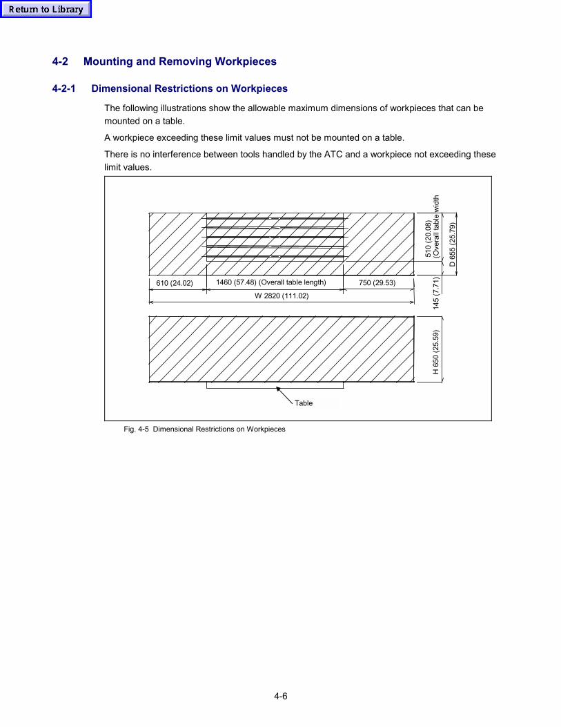
4-6
4-2 Mounting and Removing Workpieces
4-2-1 Dimensional Restrictions on Workpieces
The following illustrations show the allowable maximum dimensions of workpieces that can bemounted on a table.
A workpiece exceeding these limit values must not be mounted on a table.
There is no interference between tools handled by the ATC and a workpiece not exceeding theselimit values.
H 6
50 (2
5.59
)
D 6
55 (2
5.79
)
(Ove
rall
tabl
e w
idth
510
(20.
08)
145
(7.7
1)750 (29.53)610 (24.02) 1460 (57.48) (Overall table length)
W 2820 (111.02)
Table
Fig. 4-5 Dimensional Restrictions on Workpieces
4-7
4-2-2 Procedure for Mounting and Removing Workpieces
Workpieces can be mounted or removed regardless of the operation mode (manual or automatic)set by the NC operation panel.
<Procedure>
(1) Set the SET UP switch (key-lock type switch) to "O" position, and remove the key.
(2) Open the operator's door.When the operator's door is opened, spindle rotation, axis movement and ATC cycle aredisabled.
(3) Mount or remove a workpiece to or from the pallet.
WARNING
� Mounting or removing a workpiece must be carried out correctly only while the operator’sdoor is open.
4-2-3 Measuring Coordinate Values
Refer to the following manual:
Programming Manual (MAZATROL) Part 2, Chapter 6 “COORDINATES MEASUREMENTFUNCTION”
4-8
4-3 Preparing Coolant
4-3-1 Selection of Coolant
Check the following points with the supplier when selecting a coolant.
1. Use a water based coolant
If oil based coolant is used, the coolant discharge quantity will be reduced and its temperaturerise will be large, increasing the likelihood of thermal displacement in the machine. In addition,there is a fire hazard associated with oil-based coolant and precautions including the provisionof fire-fighting equipment are required if it is used.
2. Take factors such as lubricity, anti-corrosive properties, and anti-foaming properties intoaccount when making the selection.
3. Check if the coolant has any harmful effects on human beings.
Since water based coolant is likely to cause skin eruptions, pay due attention to the healthmanagement of the machine operators.
4. Check if the coolant will cause chemical products such as rubber and plastics to harden orexpand.
5. Check if any problems will arise as a result of mixing of the coolant with the recommendedlubricating oil for the machine.
In rare cases a chemical change can result from the mixing of coolant and lubricating oil,causing discoloration and coagulation of the coolant.
4-3-2 Replenishing Coolant
Refer to the following when replenishing coolant.
Maintenance manualSection 4-3-5, “Changing and Replenishing Coolant”.
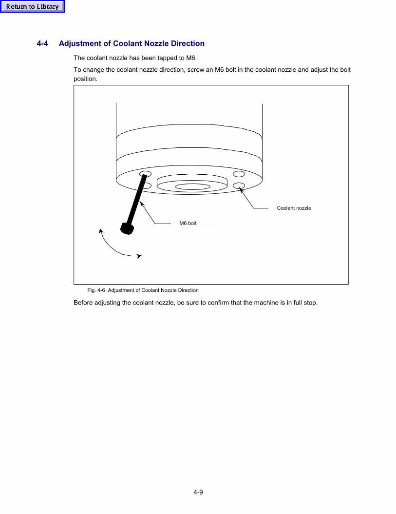
4-9
4-4 Adjustment of Coolant Nozzle Direction
The coolant nozzle has been tapped to M6.
To change the coolant nozzle direction, screw an M6 bolt in the coolant nozzle and adjust the boltposition.
Coolant nozzle
M6 bolt
Fig. 4-6 Adjustment of Coolant Nozzle Direction
Before adjusting the coolant nozzle, be sure to confirm that the machine is in full stop.

4-10
- MEMO -

Section 3:
Operating NC Unitand
Preparation for Auto Operation

Notes:
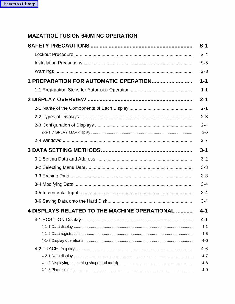
MAZATROL FUSION 640M NC OPERATION
SAFETY PRECAUTIONS S-1....................................................................
Lockout Procedure S-4............................................................................................
Installation Precautions S-5.....................................................................................
Warnings S-8...........................................................................................................
1 PREPARATION FOR AUTOMATIC OPERATION 1-1...........................
1-1 Preparation Steps for Automatic Operation 1-1................................................
2 DISPLAY OVERVIEW 2-1......................................................................
2-1 Name of the Components of Each Display 2-1.................................................
2-2 Types of Displays 2-3........................................................................................
2-3 Configuration of Displays 2-4............................................................................
2-3-1 DISPLAY MAP display 2-6...............................................................................................
2-4 Windows 2-7......................................................................................................
3 DATA SETTING METHODS 3-1.............................................................
3-1 Setting Data and Address 3-2...........................................................................
3-2 Selecting Menu Data 3-3...................................................................................
3-3 Erasing Data 3-3...............................................................................................
3-4 Modifying Data 3-4............................................................................................
3-5 Incremental Input 3-4........................................................................................
3-6 Saving Data onto the Hard Disk 3-4..................................................................
4 DISPLAYS RELATED TO THE MACHINE OPERATIONAL 4-1...........
4-1 POSITION Display 4-1......................................................................................
4-1-1 Data display 4-1...............................................................................................................
4-1-2 Data registration 4-5.........................................................................................................
4-1-3 Display operations 4-6......................................................................................................
4-2 TRACE Display 4-6...........................................................................................
4-2-1 Data display 4-7...............................................................................................................
4-1-2 Displaying machining shape and tool tip 4-8....................................................................
4-1-3 Plane select 4-9................................................................................................................
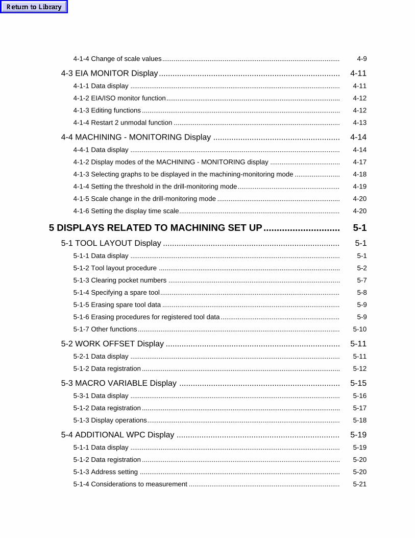
4-1-4 Change of scale values 4-9..............................................................................................
4-3 EIA MONITOR Display 4-11................................................................................
4-1-1 Data display 4-11...............................................................................................................
4-1-2 EIA/ISO monitor function 4-12............................................................................................
4-1-3 Editing functions 4-12.........................................................................................................
4-1-4 Restart 2 unmodal function 4-13........................................................................................
4-4 MACHINING - MONITORING Display 4-14........................................................
4-4-1 Data display 4-14...............................................................................................................
4-1-2 Display modes of the MACHINING - MONITORING display 4-17.....................................
4-1-3 Selecting graphs to be displayed in the machining-monitoring mode 4-18........................
4-1-4 Setting the threshold in the drill-monitoring mode 4-19......................................................
4-1-5 Scale change in the drill-monitoring mode 4-20.................................................................
4-1-6 Setting the display time scale 4-20.....................................................................................
5 DISPLAYS RELATED TO MACHINING SET UP 5-1.............................
5-1 TOOL LAYOUT Display 5-1..............................................................................
5-1-1 Data display 5-1...............................................................................................................
5-1-2 Tool layout procedure 5-2................................................................................................
5-1-3 Clearing pocket numbers 5-7...........................................................................................
5-1-4 Specifying a spare tool 5-8...............................................................................................
5-1-5 Erasing spare tool data 5-9..............................................................................................
5-1-6 Erasing procedures for registered tool data 5-9...............................................................
5-1-7 Other functions 5-10...........................................................................................................
5-2 WORK OFFSET Display 5-11.............................................................................
5-2-1 Data display 5-11...............................................................................................................
5-1-2 Data registration 5-12.........................................................................................................
5-3 MACRO VARIABLE Display 5-15.......................................................................
5-3-1 Data display 5-16...............................................................................................................
5-1-2 Data registration 5-17.........................................................................................................
5-1-3 Display operations 5-18......................................................................................................
5-4 ADDITIONAL WPC Display 5-19........................................................................
5-1-1 Data display 5-19...............................................................................................................
5-1-2 Data registration 5-20.........................................................................................................
5-1-3 Address setting 5-20..........................................................................................................
5-1-4 Considerations to measurement 5-21................................................................................
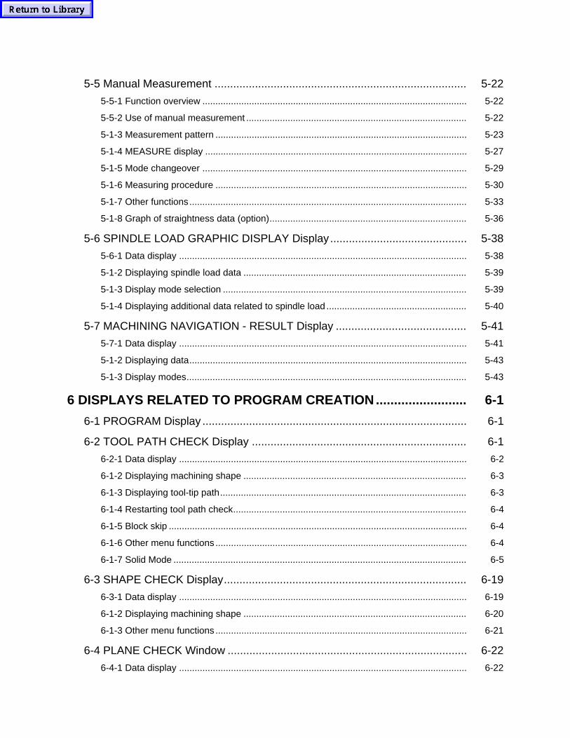
5-5 Manual Measurement 5-22.................................................................................
5-5-1 Function overview 5-22......................................................................................................
5-5-2 Use of manual measurement 5-22.....................................................................................
5-1-3 Measurement pattern 5-23.................................................................................................
5-1-4 MEASURE display 5-27.....................................................................................................
5-1-5 Mode changeover 5-29......................................................................................................
5-1-6 Measuring procedure 5-30.................................................................................................
5-1-7 Other functions 5-33...........................................................................................................
5-1-8 Graph of straightness data (option) 5-36............................................................................
5-6 SPINDLE LOAD GRAPHIC DISPLAY Display 5-38............................................
5-6-1 Data display 5-38...............................................................................................................
5-1-2 Displaying spindle load data 5-39......................................................................................
5-1-3 Display mode selection 5-39..............................................................................................
5-1-4 Displaying additional data related to spindle load 5-40......................................................
5-7 MACHINING NAVIGATION - RESULT Display 5-41..........................................
5-7-1 Data display 5-41...............................................................................................................
5-1-2 Displaying data 5-43...........................................................................................................
5-1-3 Display modes 5-43............................................................................................................
6 DISPLAYS RELATED TO PROGRAM CREATION 6-1.........................
6-1 PROGRAM Display 6-1.....................................................................................
6-2 TOOL PATH CHECK Display 6-1.....................................................................
6-2-1 Data display 6-2...............................................................................................................
6-1-2 Displaying machining shape 6-3......................................................................................
6-1-3 Displaying tool-tip path 6-3...............................................................................................
6-1-4 Restarting tool path check 6-4..........................................................................................
6-1-5 Block skip 6-4...................................................................................................................
6-1-6 Other menu functions 6-4.................................................................................................
6-1-7 Solid Mode 6-5.................................................................................................................
6-3 SHAPE CHECK Display 6-19..............................................................................
6-3-1 Data display 6-19...............................................................................................................
6-1-2 Displaying machining shape 6-20......................................................................................
6-1-3 Other menu functions 6-21.................................................................................................
6-4 PLANE CHECK Window 6-22.............................................................................
6-4-1 Data display 6-22...............................................................................................................
6-1-2 Displaying machining shape 6-23......................................................................................
6-1-3 Others 6-23........................................................................................................................
6-5 SECTION CHECK Window 6-23.........................................................................
6-5-1 Data display 6-24...............................................................................................................
6-1-2 Displaying sectional shapes 6-25.......................................................................................
6-1-3 Others 6-25........................................................................................................................
6-6 PROGRAM FILE Display 6-26............................................................................
6-6-1 Data display 6-26...............................................................................................................
6-1-2 Program name setting 6-27................................................................................................
6-1-3 Work number change 6-28.................................................................................................
6-1-4 Program erasure 6-28........................................................................................................
6-1-5 Program copy 6-29.............................................................................................................
6-1-6 All program erasure 6-29....................................................................................................
6-1-7 Converting MAZATROL program to EIA/ISO program 6-29..............................................
6-1-8 Opening the shape drawing window 6-29..........................................................................
6-1-9 Directory change 6-30........................................................................................................
6-1-10 Program transfer 6-31......................................................................................................
6-1-11 Program management functions 6-31..............................................................................
6-7 PROCESS CONTROL Display 6-33...................................................................
6-7-1 Data display 6-33...............................................................................................................
6-1-2 Process-number search 6-34.............................................................................................
6-1-3 Other functions 6-34...........................................................................................................
6-8 PROGRAM LAYOUT Display 6-35.....................................................................
6-8-1 Data display 6-35...............................................................................................................
6-1-2 Priority number setting 6-36...............................................................................................
6-1-3 Delay priority designation 6-36...........................................................................................
6-1-4 Priority number assignment 6-36.......................................................................................
6-1-5 Priority number movement 6-37.........................................................................................
6-1-6 Priority number all erase 6-38............................................................................................
6-1-7 Store 6-38...........................................................................................................................
6-1-8 Program write 6-38.............................................................................................................
6-1-9 Simultaneous use of functions 6-39...................................................................................
6-1-10 Program reference window 6-39......................................................................................
6-9 MACHINING NAVIGATION - PREDICT Display 6-40.........................................
6-9-1 Data display 6-40...............................................................................................................
6-1-2 Displaying data 6-43...........................................................................................................
6-1-3 Display modes 6-44............................................................................................................
6-1-4 Modifying the cutting conditions 6-46.................................................................................
7 DISPLAYS RELATED TO TOOLS 7-1...................................................
7-1 TOOL DATA Display 7-1...................................................................................
7-1-1 Data display 7-1...............................................................................................................
7-1-2 Tool-data input procedures (for MAZATROL programs) 7-3............................................
7-1-3 Interchanging pocket numbers (for MAZATROL programs) 7-7......................................
7-1-4 Registering the tools to be used 7-8.................................................................................
7-1-5 Manual measurement of the tool lengths 7-9...................................................................
7-1-6 Other functions (for MAZATROL programs) 7-10..............................................................
7-1-7 Setting tool data (for EIA/ISO programs) 7-13...................................................................
7-1-8 Setting tool group numbers 7-16........................................................................................
7-1-9 Manual measurement of tool lengths (Setting tool length offset data using 7-17...............
7-1-10 Other functions (for EIA/ISO programs) 7-17...................................................................
7-1-11 MAZATROL tool data �INVALIDATION� (Option) 7-17.....................................................
7-1-12 Tool length listing window 7-21........................................................................................
7-2 TOOL FILE Display 7-22.....................................................................................
7-1-1 Data display 7-23...............................................................................................................
7-1-2 Registering milling tool data 7-25.......................................................................................
7-1-3 Erasing a part of the registered data 7-29..........................................................................
7-3 TOOL OFFSET Display 7-30..............................................................................
7-3-1 Data display 7-30...............................................................................................................
7-1-2 Tool-compensation data setting procedures 7-31..............................................................
7-1-3 Setting the current position 7-33........................................................................................
7-1-4 EIA/ISO tool length measurement 7-33..............................................................................
8 DISPLAYS RELATED TO PARAMETERS 8-1......................................
8-1 CUTTING CONDITION (W.-MAT./T.-MAT.) Display 8-1...................................
8-1-1 Data display 8-1...............................................................................................................
8-1-2 Registering data 8-2.........................................................................................................
8-1-3 Read and Write of text file 8-3..........................................................................................
8-2 CUTTING CONDITION Display 8-5..................................................................
8-2-1 Data display 8-5...............................................................................................................
8-2-2 Data registration 8-7.........................................................................................................
8-3 USER PARAMETER Display 8-8......................................................................
8-3-1 Data display 8-8...............................................................................................................
8-4 MACHINE PARAMETER Display 8-10...............................................................
8-4-1 Data display 8-10...............................................................................................................
9 DISPLAY RELATED TO DATA STORAGE 9-1.....................................
9-1 DATA I/O Display 9-1........................................................................................
9-1-1 Data display 9-1...............................................................................................................
9-1-2 DATA I/O operations (CARD) 9-2....................................................................................
9-1-3 DATA I/O operations (CMT) 9-6.......................................................................................
9-1-4 DATA I/O operations (TAPE) 9-10.....................................................................................
9-1-5 DATA I/O operations (FLOPPY) 9-14................................................................................
9-1-6 DATA I/O operations (DNC) 9-16.......................................................................................
9-1-7 DATA I/O operations (HARD DISK) 9-20...........................................................................
9-2 Program Transfer from the Host PC to the Memory Card 9-23...........................
9-2-1 Outline 9-23........................................................................................................................
9-2-2 Detailed description 9-23....................................................................................................
10 DISPLAYS RELATED TO DIAGNOSIS 10-1.........................................
10-1 DIAGNOSIS (USER) � ALARM Display 10-1.....................................................
10-1-1 Data display 10-2.............................................................................................................
10-2 DIAGNOSIS (USER) � ALARM HISTORY Display 10-5....................................
10-2-1 Data display 10-5.............................................................................................................
10-3 DIAGNOSIS (USER) � PLC SIGNAL Display 10-6............................................
10-1-1 Data display 10-6.............................................................................................................
10-4 MAINTENANCE CHECK Display 10-7..............................................................
10-1-1 Data display 10-7.............................................................................................................
10-1-2 Data display for long-term check items (1500 and 3000 hours check items) 10-8...........
10-1-3 Display operations 10-8....................................................................................................
10-1-4 Entry of the check items to be displayed 10-9..................................................................
10-5 PLC Display 10-11..............................................................................................
10-5-1 Data display 10-11.............................................................................................................
10-6 RUNNING CONTROL Display 10-12..................................................................
10-6-1 Data display 10-12.............................................................................................................
10-1-2 Display modes 10-15..........................................................................................................
10-7 DIAGNOSIS (MAKER) � VERSION Display 10-18..............................................
10-1-1 Data display 10-18.............................................................................................................
10-8 DIAGNOSIS (MAKER) � DIAGNOSIS MONITOR Display 10-19........................
10-1-1 Data display 10-19.............................................................................................................
10-1-2 Display operations 10-20....................................................................................................
10-9 DIAGNOSIS (MAKER) � OPTION Display 10-23................................................
10-9-1 Data display 10-23.............................................................................................................
11 OPTION 11-1...........................................................................................
11-1 Machining Management Functions 11-1...........................................................
11-1-1 General 11-1....................................................................................................................
11-1-2 PALLET MANAGEMENT display 11-2.............................................................................
11-1-3 Scheduled-operation function 11-3..................................................................................
11-1-4 External unit skipping function 11-9.................................................................................
11-1-5 External multi-piece machining function 11-11...................................................................
11-1-6 Jig offsetting function 11-13...............................................................................................
11-1-7 Parameters 11-16...............................................................................................................
11-1-8 Machining management data writing macro-program 11-16..............................................
11-2 Function Relating EIA/ISO Program (Option) 11-21...........................................
11-2-1 Configuration of displays 11-21..........................................................................................
11-2-2 POSITION display 11-24....................................................................................................
11-3 Workpiece Measurement Printout System 11-26................................................
11-3-1 Function overview 11-26....................................................................................................
11-1-2 System configurations 11-32..............................................................................................
11-1-3 Parameter registration 11-34..............................................................................................
11-1-4 Program configuration 11-37..............................................................................................
11-1-5 Explanations of macro programs 11-42.............................................................................
11-1-6 Program and measurement pattern chart 11-64................................................................
11-1-7 Output of measurement results 11-65................................................................................
11-1-8 Alarm displays 11-68..........................................................................................................
11-1-9 Program and printout example 11-69.................................................................................
11-4 Geometry Compensation Function 11-74...........................................................
11-4-1 Function general 11-74......................................................................................................
11-4-2 Detailed description 11-76..................................................................................................
11-1-3 Hold Status 11-81...............................................................................................................
11-1-4 Notes 11-82........................................................................................................................
11-1-5 Parameters 11-82...............................................................................................................
11-1-6 Appendix 11-83..................................................................................................................
11-5 Hard Disk Operating Function 11-86...................................................................
11-5-1 Outline 11-86......................................................................................................................
11-5-2 Preparation for HD operation 11-86...................................................................................
11-5-3 Selection of operation mode 11-86....................................................................................
11-1-4 Program selection for HD operation 11-88.........................................................................
11-1-5 Restart in the HD operation mode 11-89............................................................................
11-1-6 Format for HD operation programs 11-89..........................................................................
11-1-7 Alarms concerned 11-91....................................................................................................
11-6 IC Memory Card Operating Function 11-92........................................................
11-6-1 Outline 11-92......................................................................................................................
11-6-2 Preparation for CARD operation 11-92..............................................................................
11-6-3 Selection of operation mode 11-92....................................................................................
11-1-4 Program selection for CARD operation 11-94....................................................................
11-1-5 Restart in the CARD operation mode 11-95.......................................................................
11-1-6 Format for CARD operation programs 11-95.....................................................................
11-1-7 Alarms concerned 11-97....................................................................................................
11-7 EIA/ISO Conversion 11-98..................................................................................
11-7-1 Outline 11-98......................................................................................................................
11-7-2 EIA conversion program format 11-99...............................................................................
11-7-3 Output data unit 11-99........................................................................................................
11-1-4 Operating procedure 11-100................................................................................................
11-1-5 Supplementary description and precautions for conversion of MAZATROL 11-100............
11-1-6 Parameter and alarm lists 11-105........................................................................................
1-1
1 PREPARATION FOR AUTOMATIC OPERATION
To machine workpieces, you must mount the tools for machining to the magazine and prepare jigs.For automatic operation, programs and other various data must be set to the NC.
This chapter describes procedures to be carried out before automatic operation.
1-1 Preparation Steps for Automatic Operation
Supposing that the tooling and adjustment of each part for operation have already been completed,the subsequent operational steps are described below.
For execution procedure for automatic operation, see Part 4, AUTOMATIC OPERATION .
Note: Carry out the automatic operation always in the following order.
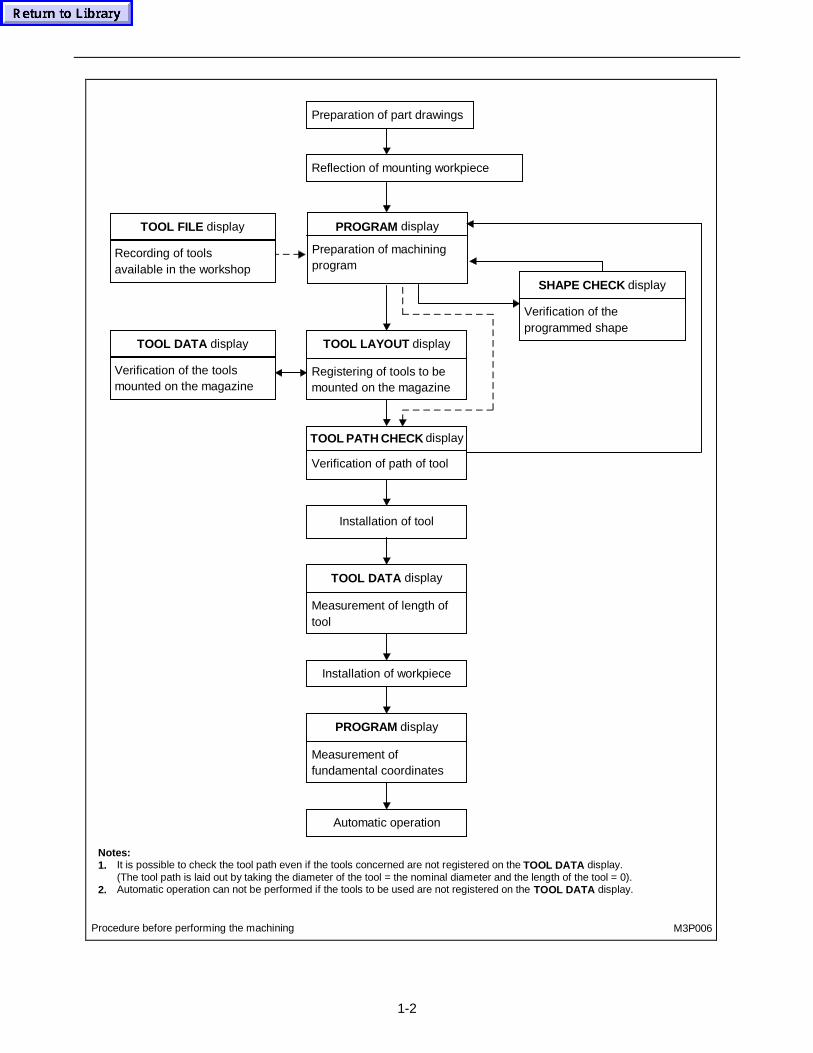
1-2
M3P006
Preparation of part drawings
Reflection of mounting workpiece
PROGRAM display
Preparation of machiningprogram
TOOL FILE display
Recording of toolsavailable in the workshop
TOOL DATA display
Verification of the toolsmounted on the magazine
TOOL LAYOUT display
Registering of tools to bemounted on the magazine
SHAPE CHECK display
Verification of theprogrammed shape
Installation of tool
TOOL DATA display
Measurement of length oftool
Installation of workpiece
PROGRAM display
Measurement offundamental coordinates
Automatic operation
Procedure before performing the machining
Notes:1. It is possible to check the tool path even if the tools concerned are not registered on the TOOL DATA display.
(The tool path is laid out by taking the diameter of the tool = the nominal diameter and the length of the tool = 0).2. Automatic operation can not be performed if the tools to be used are not registered on the TOOL DATA display.
TOOL PATH CHECK display
Verification of path of tool
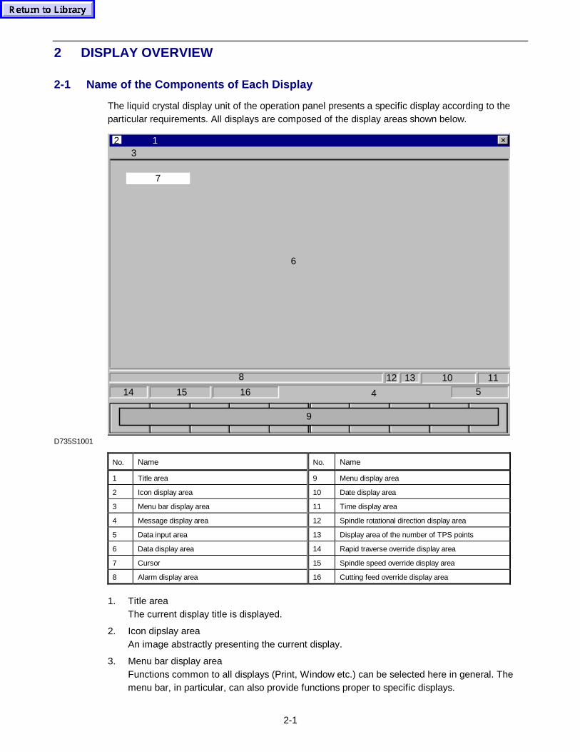
2-1
2 DISPLAY OVERVIEW
2-1 Name of the Components of Each Display
The liquid crystal display unit of the operation panel presents a specific display according to theparticular requirements. All displays are composed of the display areas shown below.
10
3
4
9
14 15 16 5
1113128
6
7
12
D735S1001
No. Name No. Name
1 Title area 9 Menu display area
2 Icon display area 10 Date display area
3 Menu bar display area 11 Time display area
4 Message display area 12 Spindle rotational direction display area
5 Data input area 13 Display area of the number of TPS points
6 Data display area 14 Rapid traverse override display area
7 Cursor 15 Spindle speed override display area
8 Alarm display area 16 Cutting feed override display area
1. Title areaThe current display title is displayed.
2. Icon dipslay areaAn image abstractly presenting the current display.
3. Menu bar display areaFunctions common to all displays (Print, Window etc.) can be selected here in general. Themenu bar, in particular, can also provide functions proper to specific displays.
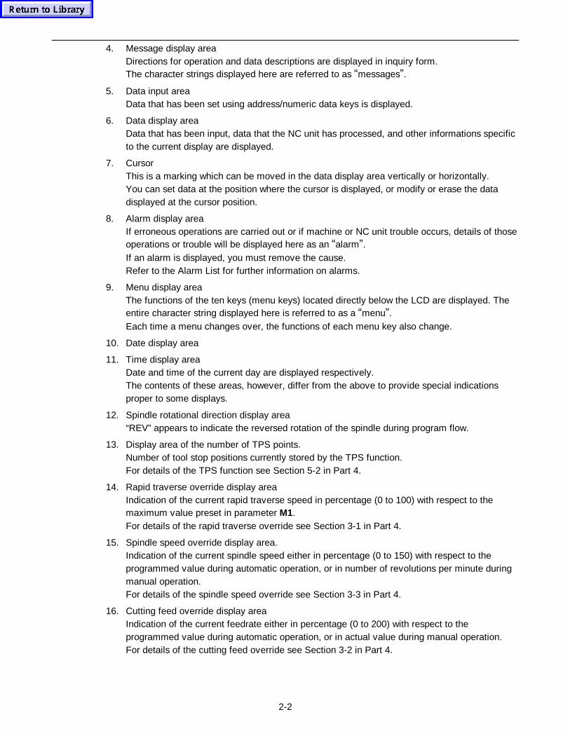
2-2
4. Message display areaDirections for operation and data descriptions are displayed in inquiry form.The character strings displayed here are referred to as “messages”.
5. Data input areaData that has been set using address/numeric data keys is displayed.
6. Data display areaData that has been input, data that the NC unit has processed, and other informations specificto the current display are displayed.
7. CursorThis is a marking which can be moved in the data display area vertically or horizontally.You can set data at the position where the cursor is displayed, or modify or erase the datadisplayed at the cursor position.
8. Alarm display areaIf erroneous operations are carried out or if machine or NC unit trouble occurs, details of thoseoperations or trouble will be displayed here as an “alarm”.If an alarm is displayed, you must remove the cause.Refer to the Alarm List for further information on alarms.
9. Menu display areaThe functions of the ten keys (menu keys) located directly below the LCD are displayed. Theentire character string displayed here is referred to as a “menu”.Each time a menu changes over, the functions of each menu key also change.
10. Date display area
11. Time display areaDate and time of the current day are displayed respectively.The contents of these areas, however, differ from the above to provide special indicationsproper to some displays.
12. Spindle rotational direction display area“REV” appears to indicate the reversed rotation of the spindle during program flow.
13. Display area of the number of TPS points.Number of tool stop positions currently stored by the TPS function.For details of the TPS function see Section 5-2 in Part 4.
14. Rapid traverse override display areaIndication of the current rapid traverse speed in percentage (0 to 100) with respect to themaximum value preset in parameter M1.For details of the rapid traverse override see Section 3-1 in Part 4.
15. Spindle speed override display area.Indication of the current spindle speed either in percentage (0 to 150) with respect to theprogrammed value during automatic operation, or in number of revolutions per minute duringmanual operation.For details of the spindle speed override see Section 3-3 in Part 4.
16. Cutting feed override display areaIndication of the current feedrate either in percentage (0 to 200) with respect to theprogrammed value during automatic operation, or in actual value during manual operation.For details of the cutting feed override see Section 3-2 in Part 4.
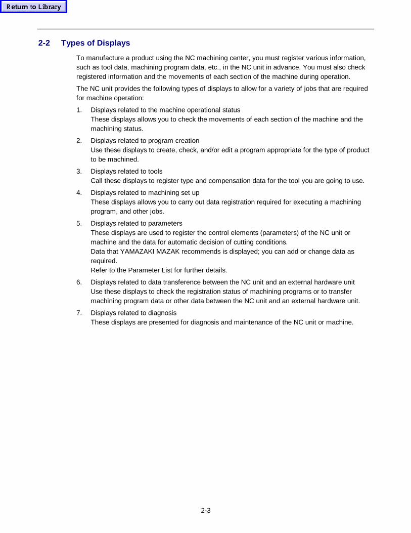
2-3
2-2 Types of Displays
To manufacture a product using the NC machining center, you must register various information,such as tool data, machining program data, etc., in the NC unit in advance. You must also checkregistered information and the movements of each section of the machine during operation.
The NC unit provides the following types of displays to allow for a variety of jobs that are requiredfor machine operation:
1. Displays related to the machine operational statusThese displays allows you to check the movements of each section of the machine and themachining status.
2. Displays related to program creationUse these displays to create, check, and/or edit a program appropriate for the type of productto be machined.
3. Displays related to toolsCall these displays to register type and compensation data for the tool you are going to use.
4. Displays related to machining set upThese displays allows you to carry out data registration required for executing a machiningprogram, and other jobs.
5. Displays related to parametersThese displays are used to register the control elements (parameters) of the NC unit ormachine and the data for automatic decision of cutting conditions.Data that YAMAZAKI MAZAK recommends is displayed; you can add or change data asrequired.Refer to the Parameter List for further details.
6. Displays related to data transference between the NC unit and an external hardware unitUse these displays to check the registration status of machining programs or to transfermachining program data or other data between the NC unit and an external hardware unit.
7. Displays related to diagnosisThese displays are presented for diagnosis and maintenance of the NC unit or machine.
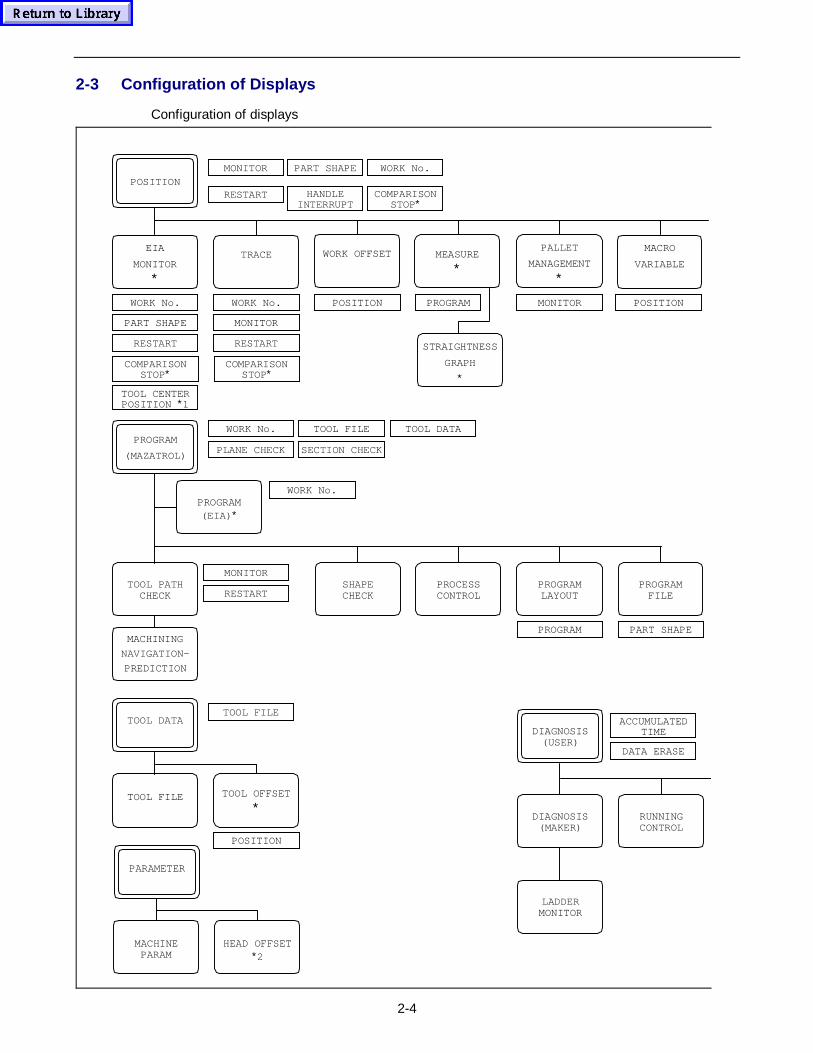
2-4
2-3 Configuration of Displays
Configuration of displays
MEASURE
∗
PALLET
MANAGEMENT
∗
MACRO
VARIABLE
RESTART
POSITIONMONITOR
PROGRAM
(MAZATROL)
TOOL PATHCHECK RESTART
MONITOR
TOOL FILE
POSITION
TOOL DATA
PARAMETER
DIAGNOSIS(MAKER)
DIAGNOSIS(USER)
RUNNINGCONTROL
LADDERMONITOR
MONITOR PART SHAPE
RESTARTPOSITION
HANDLEINTERRUPT
COMPARISONSTOP∗
COMPARISONSTOP∗
COMPARISONSTOP∗
WORK No.
WORK No.
WORK No.
RESTART
PROGRAM(EIA) ∗
PART SHAPE
WORK No.
WORK No.
MONITOR
TOOL FILE
POSITION PROGRAM
TRACE
PROCESSCONTROL
PROGRAMLAYOUT
PROGRAMFILE
PROGRAM PART SHAPE
TOOL OFFSET
∗
TOOL FILE
MACHINEPARAM
HEAD OFFSET∗2
ACCUMULATEDTIME
TOOL CENTERPOSITION ∗1
SECTION CHECKPLANE CHECK
EIA
MONITOR
∗
WORK OFFSET
DATA ERASE
STRAIGHTNESS
GRAPH
∗
TOOL DATA
SHAPECHECK
MACHINING
NAVIGATION-
PREDICTION
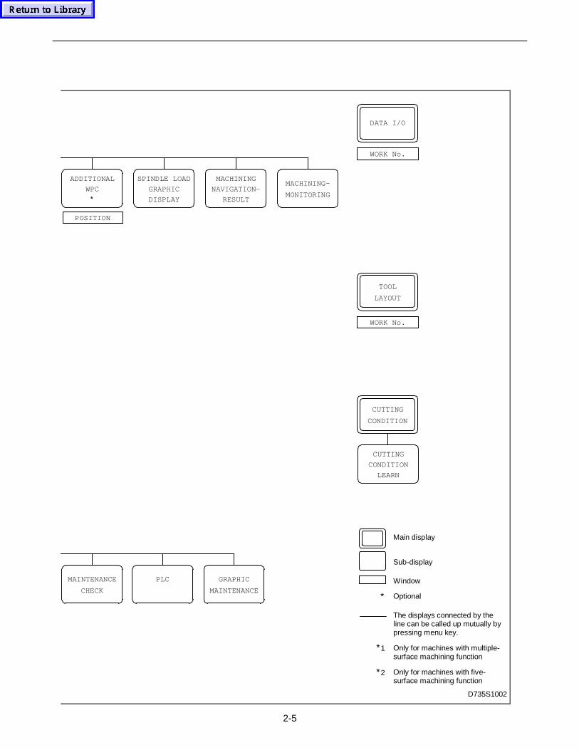
2-5
∗
Main display
Sub-display
Window
Optional
The displays connected by theline can be called up mutually bypressing menu key.
Only for machines with multiple-surface machining function
Only for machines with five-surface machining function
DATA I/O
WORK No.
WORK No.
MAINTENANCE
CHECK
PLC GRAPHIC
MAINTENANCE
ADDITIONAL
WPC
∗
POSITION
TOOL
LAYOUT
∗2
∗1
SPINDLE LOAD
GRAPHIC
DISPLAY
MACHINING
NAVIGATION-
RESULT
MACHINING-
MONITORING
CUTTING
CONDITION
D735S1002
CUTTING
CONDITION
LEARN
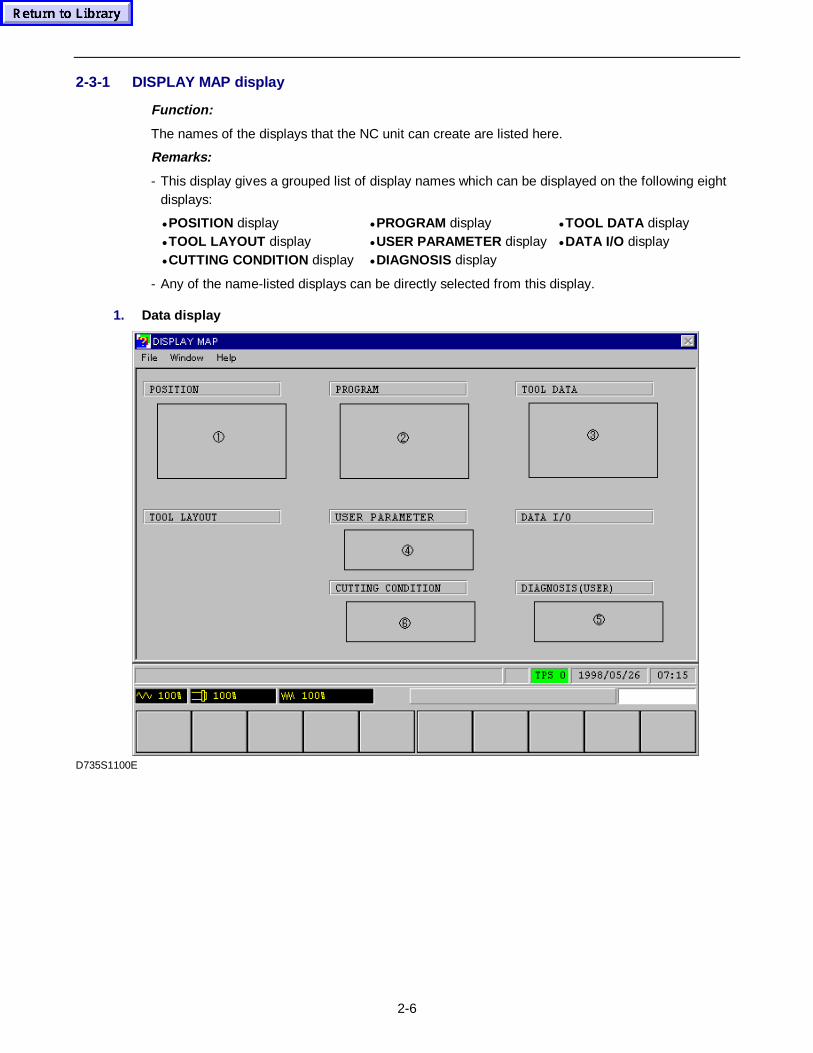
2-6
2-3-1 DISPLAY MAP display
Function:
The names of the displays that the NC unit can create are listed here.
Remarks:
- This display gives a grouped list of display names which can be displayed on the following eightdisplays:
• POSITION display • PROGRAM display • TOOL DATA display• TOOL LAYOUT display • USER PARAMETER display • DATA I/O display• CUTTING CONDITION display • DIAGNOSIS display
- Any of the name-listed displays can be directly selected from this display.
1. Data display
D735S1100E
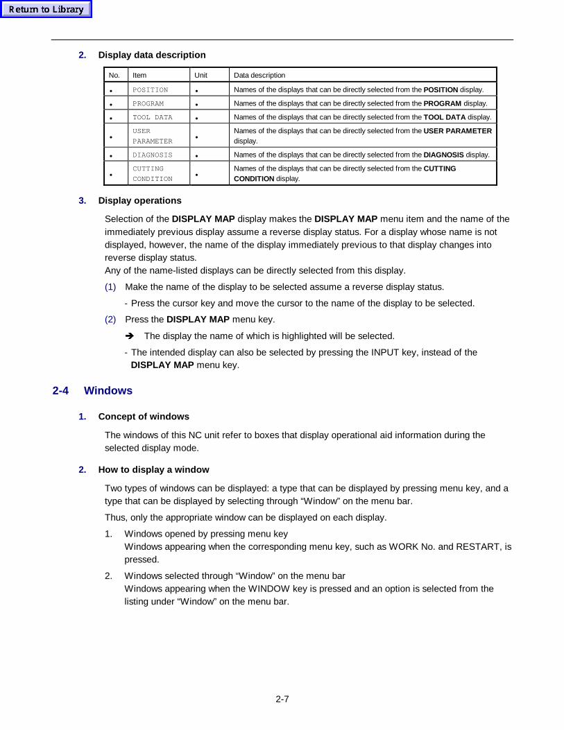
2-7
2. Display data description
No. Item Unit Data description
• POSITION • Names of the displays that can be directly selected from the POSITION display.
• PROGRAM • Names of the displays that can be directly selected from the PROGRAM display.
• TOOL DATA • Names of the displays that can be directly selected from the TOOL DATA display.
•USER
PARAMETER•
Names of the displays that can be directly selected from the USER PARAMETERdisplay.
• DIAGNOSIS • Names of the displays that can be directly selected from the DIAGNOSIS display.
•CUTTING
CONDITION•
Names of the displays that can be directly selected from the CUTTINGCONDITION display.
3. Display operat ions
Selection of the DISPLAY MAP display makes the DISPLAY MAP menu item and the name of theimmediately previous display assume a reverse display status. For a display whose name is notdisplayed, however, the name of the display immediately previous to that display changes intoreverse display status.Any of the name-listed displays can be directly selected from this display.
(1) Make the name of the display to be selected assume a reverse display status.
- Press the cursor key and move the cursor to the name of the display to be selected.
(2) Press the DISPLAY MAP menu key.
Î The display the name of which is highlighted will be selected.
- The intended display can also be selected by pressing the INPUT key, instead of theDISPLAY MAP menu key.
2-4 Windows
1. Concept of windows
The windows of this NC unit refer to boxes that display operational aid information during theselected display mode.
2. How to display a window
Two types of windows can be displayed: a type that can be displayed by pressing menu key, and atype that can be displayed by selecting through “Window” on the menu bar.
Thus, only the appropriate window can be displayed on each display.
1. Windows opened by pressing menu keyWindows appearing when the corresponding menu key, such as WORK No. and RESTART, ispressed.
2. Windows selected through “Window” on the menu barWindows appearing when the WINDOW key is pressed and an option is selected from thelisting under “Window” on the menu bar.
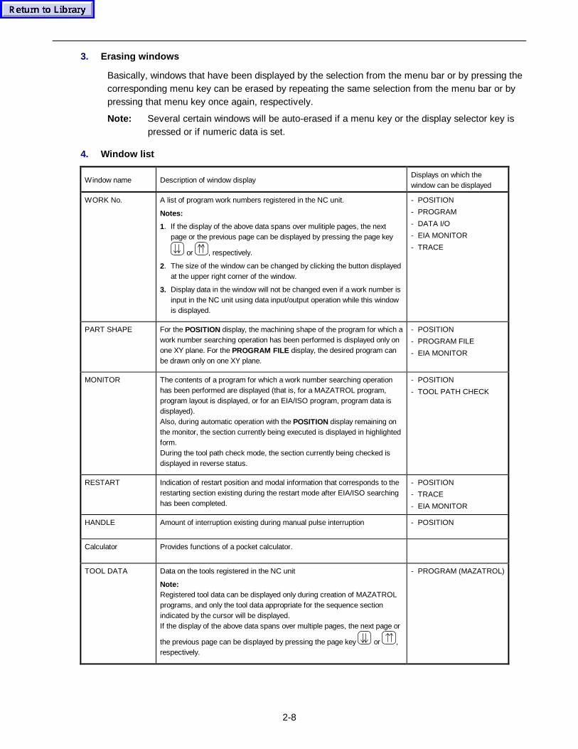
2-8
3. Erasing windows
Basically, windows that have been displayed by the selection from the menu bar or by pressing thecorresponding menu key can be erased by repeating the same selection from the menu bar or bypressing that menu key once again, respectively.
Note: Several certain windows will be auto-erased if a menu key or the display selector key ispressed or if numeric data is set.
4. Window list
Window name Description of window displayDisplays on which thewindow can be displayed
WORK No. A list of program work numbers registered in the NC unit.
Notes:
1. If the display of the above data spans over mulitiple pages, the nextpage or the previous page can be displayed by pressing the page key
or , respectively.
2. The size of the window can be changed by clicking the button displayedat the upper right corner of the window.
3. Display data in the window will not be changed even if a work number isinput in the NC unit using data input/output operation while this windowis displayed.
- POSITION
- PROGRAM
- DATA I/O
- EIA MONITOR
- TRACE
PART SHAPE For the POSITION display, the machining shape of the program for which awork number searching operation has been performed is displayed only onone XY plane. For the PROGRAM FILE display, the desired program canbe drawn only on one XY plane.
- POSITION
- PROGRAM FILE
- EIA MONITOR
MONITOR The contents of a program for which a work number searching operationhas been performed are displayed (that is, for a MAZATROL program,program layout is displayed, or for an EIA/ISO program, program data isdisplayed).Also, during automatic operation with the POSITION display remaining onthe monitor, the section currently being executed is displayed in highlightedform.During the tool path check mode, the section currently being checked isdisplayed in reverse status.
- POSITION
- TOOL PATH CHECK
RESTART Indication of restart position and modal information that corresponds to therestarting section existing during the restart mode after EIA/ISO searchinghas been completed.
- POSITION
- TRACE
- EIA MONITOR
HANDLE Amount of interruption existing during manual pulse interruption - POSITION
Calculator Provides functions of a pocket calculator.
TOOL DATA Data on the tools registered in the NC unit
Note:Registered tool data can be displayed only during creation of MAZATROLprograms, and only the tool data appropriate for the sequence sectionindicated by the cursor will be displayed.If the display of the above data spans over multiple pages, the next page or
the previous page can be displayed by pressing the page key or ,respectively.
- PROGRAM (MAZATROL)
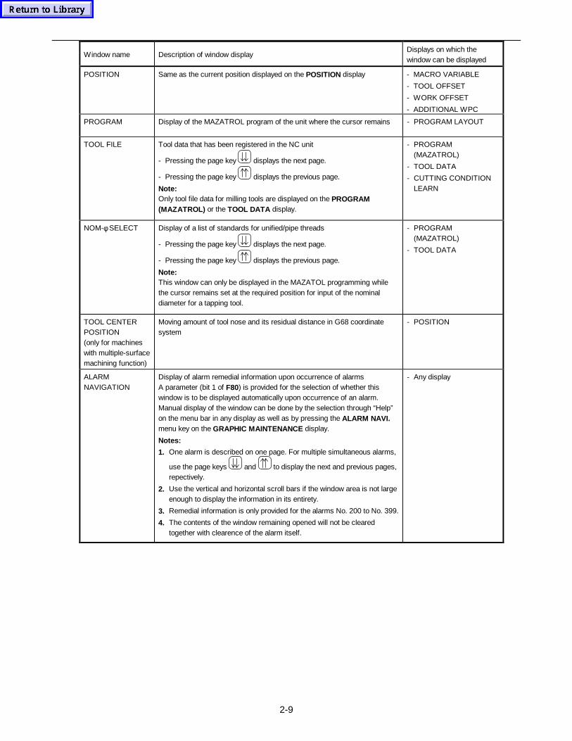
2-9
Window name Description of window displayDisplays on which thewindow can be displayed
POSITION Same as the current position displayed on the POSITION display - MACRO VARIABLE
- TOOL OFFSET
- WORK OFFSET
- ADDITIONAL WPC
PROGRAM Display of the MAZATROL program of the unit where the cursor remains - PROGRAM LAYOUT
TOOL FILE Tool data that has been registered in the NC unit
- Pressing the page key displays the next page.
- Pressing the page key displays the previous page.
Note:Only tool file data for milling tools are displayed on the PROGRAM(MAZATROL) or the TOOL DATA display.
- PROGRAM(MAZATROL)
- TOOL DATA
- CUTTING CONDITIONLEARN
NOM-φ SELECT Display of a list of standards for unified/pipe threads
- Pressing the page key displays the next page.
- Pressing the page key displays the previous page.
Note:This window can only be displayed in the MAZATOL programming whilethe cursor remains set at the required position for input of the nominaldiameter for a tapping tool.
- PROGRAM(MAZATROL)
- TOOL DATA
TOOL CENTERPOSITION(only for machineswith multiple-surfacemachining function)
Moving amount of tool nose and its residual distance in G68 coordinatesystem
- POSITION
ALARMNAVIGATION
Display of alarm remedial information upon occurrence of alarmsA parameter (bit 1 of F80) is provided for the selection of whether thiswindow is to be displayed automatically upon occurrence of an alarm.Manual display of the window can be done by the selection through “Help”on the menu bar in any display as well as by pressing the ALARM NAVI.menu key on the GRAPHIC MAINTENANCE display.
Notes:
1. One alarm is described on one page. For multiple simultaneous alarms,
use the page keys and to display the next and previous pages,repectively.
2. Use the vertical and horizontal scroll bars if the window area is not largeenough to display the information in its entirety.
3. Remedial information is only provided for the alarms No. 200 to No. 399.
4. The contents of the window remaining opened will not be clearedtogether with clearence of the alarm itself.
- Any display

2-10
- NOTE -
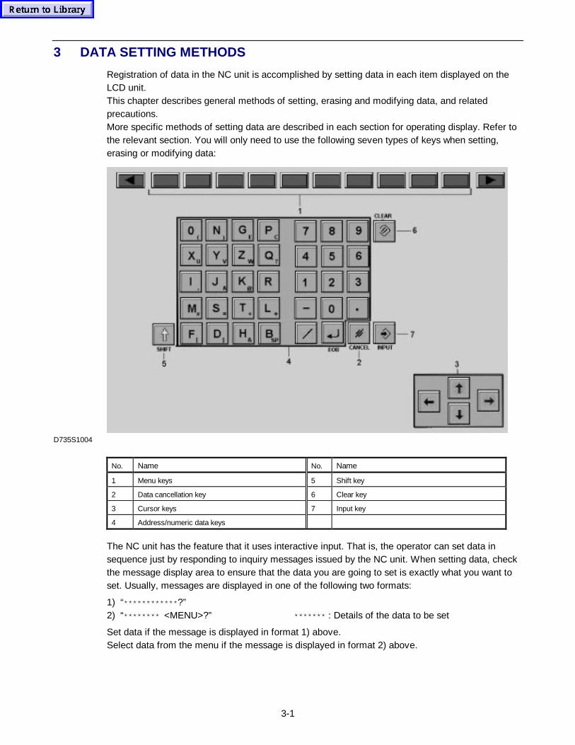
3-1
3 DATA SETTING METHODS
Registration of data in the NC unit is accomplished by setting data in each item displayed on theLCD unit.This chapter describes general methods of setting, erasing and modifying data, and relatedprecautions.More specific methods of setting data are described in each section for operating display. Refer tothe relevant section. You will only need to use the following seven types of keys when setting,erasing or modifying data:
D735S1004
No. Name No. Name
1 Menu keys 5 Shift key
2 Data cancellation key 6 Clear key
3 Cursor keys 7 Input key
4 Address/numeric data keys
The NC unit has the feature that it uses interactive input. That is, the operator can set data insequence just by responding to inquiry messages issued by the NC unit. When setting data, checkthe message display area to ensure that the data you are going to set is exactly what you want toset. Usually, messages are displayed in one of the following two formats:
1) “************ ?”2) “******** <MENU>?” ******* : Details of the data to be set
Set data if the message is displayed in format 1) above.Select data from the menu if the message is displayed in format 2) above.
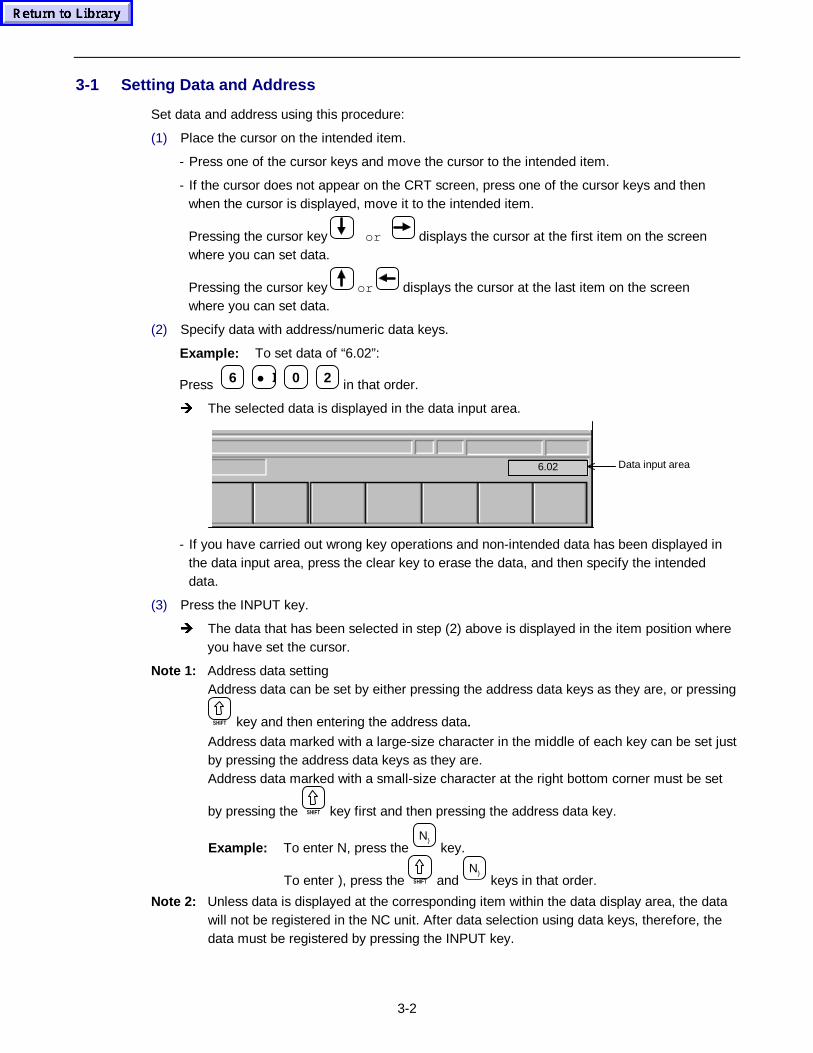
3-2
3-1 Setting Data and Address
Set data and address using this procedure:
(1) Place the cursor on the intended item.
- Press one of the cursor keys and move the cursor to the intended item.
- If the cursor does not appear on the CRT screen, press one of the cursor keys and thenwhen the cursor is displayed, move it to the intended item.
Pressing the cursor key or displays the cursor at the first item on the screenwhere you can set data.
Pressing the cursor key or displays the cursor at the last item on the screenwhere you can set data.
(2) Specify data with address/numeric data keys.
Example: To set data of “6.02”:
Press 6 • E 0 2 in that order.
Î The selected data is displayed in the data input area.
Data input area6.02
- If you have carried out wrong key operations and non-intended data has been displayed inthe data input area, press the clear key to erase the data, and then specify the intendeddata.
(3) Press the INPUT key.
Î The data that has been selected in step (2) above is displayed in the item position whereyou have set the cursor.
Note 1: Address data settingAddress data can be set by either pressing the address data keys as they are, or pressing
SHIFT key and then entering the address data.Address data marked with a large-size character in the middle of each key can be set justby pressing the address data keys as they are.Address data marked with a small-size character at the right bottom corner must be set
by pressing the SHIFT key first and then pressing the address data key.
Example: To enter N, press the N)
key.
To enter ), press the SHIFT and N)
keys in that order.
Note 2: Unless data is displayed at the corresponding item within the data display area, the datawill not be registered in the NC unit. After data selection using data keys, therefore, thedata must be registered by pressing the INPUT key.
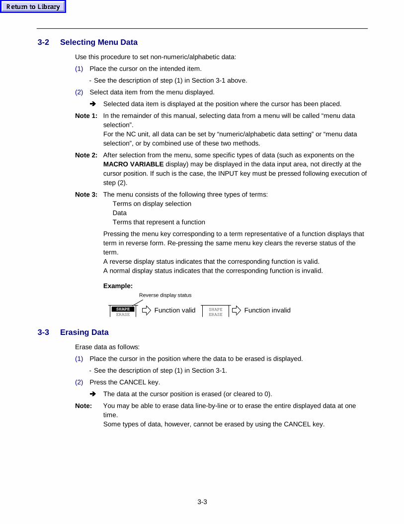
3-3
3-2 Selecting Menu Data
Use this procedure to set non-numeric/alphabetic data:
(1) Place the cursor on the intended item.
- See the description of step (1) in Section 3-1 above.
(2) Select data item from the menu displayed.
Î Selected data item is displayed at the position where the cursor has been placed.
Note 1: In the remainder of this manual, selecting data from a menu will be called “menu dataselection”.For the NC unit, all data can be set by “numeric/alphabetic data setting” or “menu dataselection”, or by combined use of these two methods.
Note 2: After selection from the menu, some specific types of data (such as exponents on theMACRO VARIABLE display) may be displayed in the data input area, not directly at thecursor position. If such is the case, the INPUT key must be pressed following execution ofstep (2).
Note 3: The menu consists of the following three types of terms:Terms on display selectionDataTerms that represent a function
Pressing the menu key corresponding to a term representative of a function displays thatterm in reverse form. Re-pressing the same menu key clears the reverse status of theterm.A reverse display status indicates that the corresponding function is valid.A normal display status indicates that the corresponding function is invalid.
Example:
SHAPEERASE
Function valid
Reverse display status
SHAPEERASE
Function invalid
3-3 Erasing Data
Erase data as follows:
(1) Place the cursor in the position where the data to be erased is displayed.
- See the description of step (1) in Section 3-1.
(2) Press the CANCEL key.
Î The data at the cursor position is erased (or cleared to 0).
Note: You may be able to erase data line-by-line or to erase the entire displayed data at onetime.Some types of data, however, cannot be erased by using the CANCEL key.
3-4
3-4 Modifying Data
Modify data as follows:
(1) Place the cursor in the position where the data to be modified is displayed.
- See the description of step (1) in Section 3-1.
(2) Set new data.
Î The data at the cursor position is overridden with the new data.
3-5 Incremental Input
During data setting, you may see the function name INCRMENT INPUT in a menu.
Using this function, you can set desired data just by selecting an incremental or decremental valuefor the original data.Effectively use this function when increasing or reducing displayed data.
The procedure for using the incremental input function is as follows:
(1) Press the INCRMENT INPUT menu key.
Î The display of INCRMENT INPUT changes to reverse display status.
(2) Select an incremental or decremental value for the original data.
Example: To reduce the data of “12.05” by –0.1:
Press −
0 • E 1 in that order.
Î The selected value is displayed in the data input area.
(3) Press the INPUT key.
Î The original data changes by the value that was selected in step (2) above.In the example shown above, the original data changes to “11.95” (= 12.05 − 0.1).
3-6 Saving Data onto the Hard Disk
This NC unit is designed so that machining programs are saved onto the hard disk. If the NC unit isaccidentally turned off by a sudden power interruption or other events, entered data may not besaved. During data entry, therefore, perform the following operations as appropriate for datastorage:
Press the PROGRAM COMPLETE menu key or change the PROGRAM display to another oneeven halfway to save the machining program as far as it is prepared.
If, moreover, the NC unit should be turned off during the operation of the hard disk, saved datamay be damaged. Store machining programs, therefore, onto IC memory cards or other media.
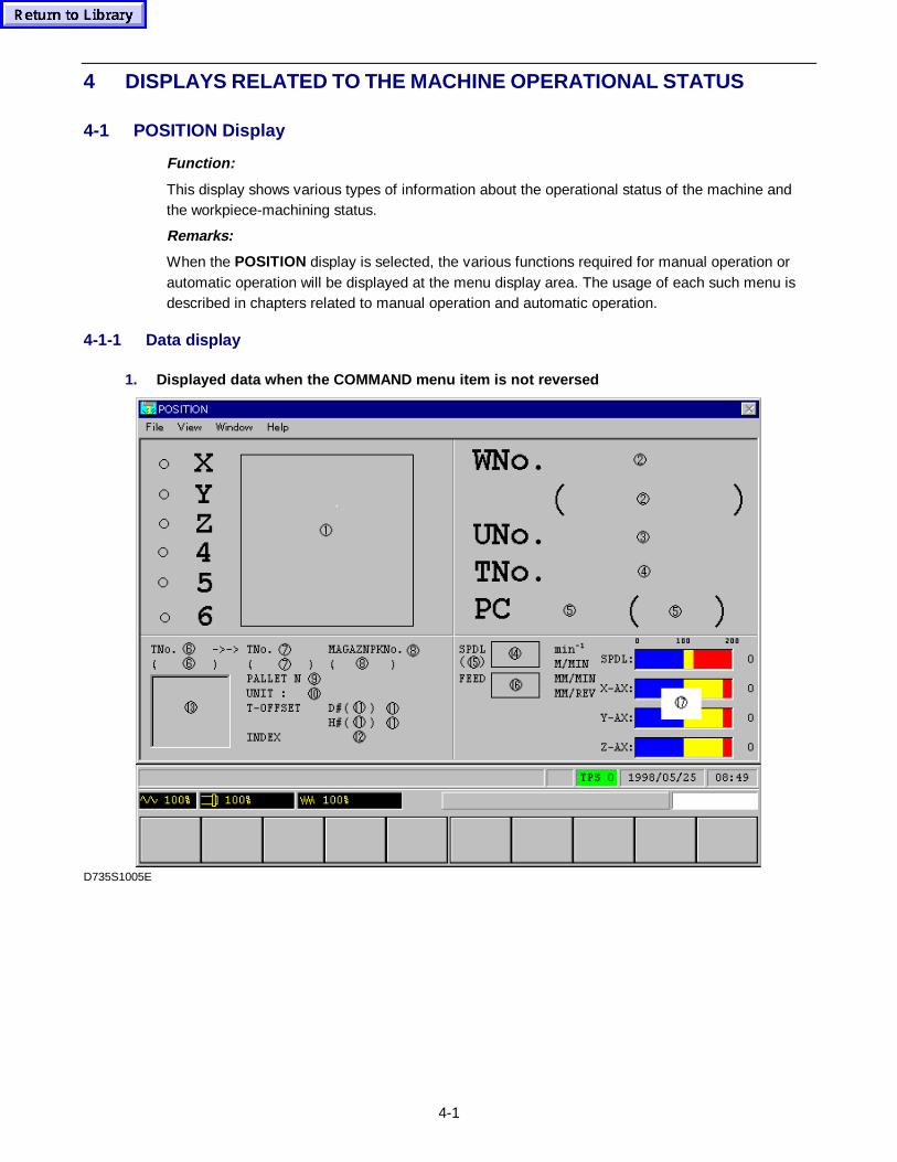
4-1
4 DISPLAYS RELATED TO THE MACHINE OPERATIONAL STATUS
4-1 POSITION Display
Function:
This display shows various types of information about the operational status of the machine andthe workpiece-machining status.
Remarks:
When the POSITION display is selected, the various functions required for manual operation orautomatic operation will be displayed at the menu display area. The usage of each such menu isdescribed in chapters related to manual operation and automatic operation.
4-1-1 Data display
1. Displayed data when the COMMAND menu item is not reversed
D735S1005E
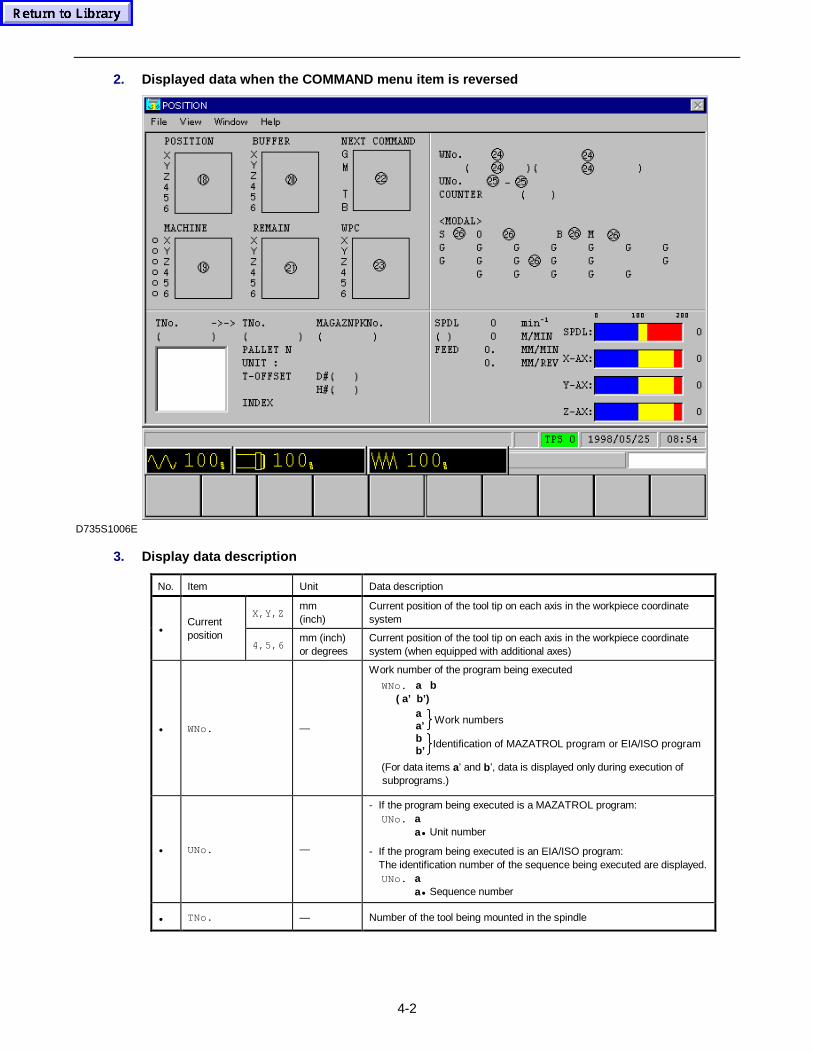
4-2
2. Displayed data when the COMMAND menu item is reversed
D735S1006E
3. Display data description
No. Item Unit Data description
X,Y,Zmm(inch)
Current position of the tool tip on each axis in the workpiece coordinatesystem
•Currentposition
4,5,6mm (inch)or degrees
Current position of the tool tip on each axis in the workpiece coordinatesystem (when equipped with additional axes)
• WNo. —
Work number of the program being executed
WNo. a b ( a’ b’)
Work numbers
Identification of MAZATROL program or EIA/ISO program
aa’bb’
(For data items a’ and b’, data is displayed only during execution ofsubprograms.)
• UNo. —
- If the program being executed is a MAZATROL program:UNo. a
a• Unit number
- If the program being executed is an EIA/ISO program:The identification number of the sequence being executed are displayed.UNo. a
a• Sequence number
• TNo. — Number of the tool being mounted in the spindle
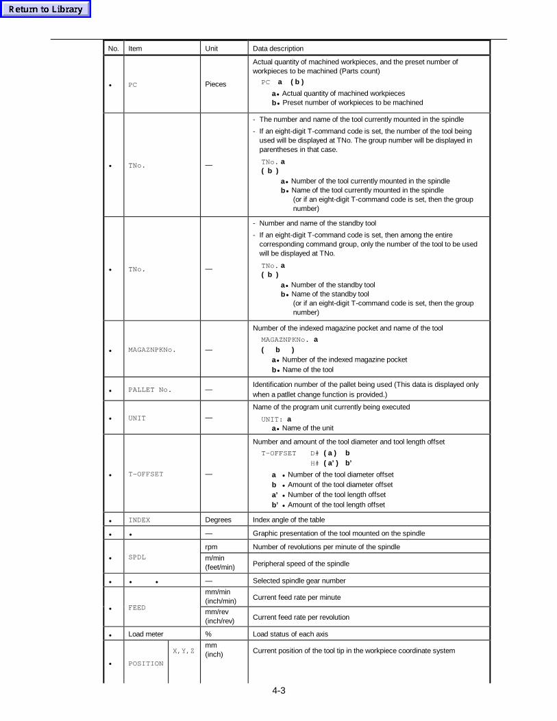
4-3
No. Item Unit Data description
• PC Pieces
Actual quantity of machined workpieces, and the preset number ofworkpieces to be machined (Parts count)
PC a ( b )
a• Actual quantity of machined workpiecesb• Preset number of workpieces to be machined
• TNo. —
- The number and name of the tool currently mounted in the spindle
- If an eight-digit T-command code is set, the number of the tool beingused will be displayed at TNo. The group number will be displayed inparentheses in that case.
TNo. a( b )
a• Number of the tool currently mounted in the spindleb• Name of the tool currently mounted in the spindle
(or if an eight-digit T-command code is set, then the groupnumber)
• TNo. —
- Number and name of the standby tool
- If an eight-digit T-command code is set, then among the entirecorresponding command group, only the number of the tool to be usedwill be displayed at TNo.
TNo. a( b )
a• Number of the standby toolb• Name of the standby tool
(or if an eight-digit T-command code is set, then the groupnumber)
• MAGAZNPKNo. —
Number of the indexed magazine pocket and name of the tool
MAGAZNPKNo. a( b )
a• Number of the indexed magazine pocketb• Name of the tool
• PALLET No. —Identification number of the pallet being used (This data is displayed onlywhen a patllet change function is provided.)
• UNIT —
Name of the program unit currently being executed
UNIT: aa• Name of the unit
• T-OFFSET —
Number and amount of the tool diameter and tool length offset
T-OFFSET D# ( a ) bH# ( a’ ) b’
a • Number of the tool diameter offsetb • Amount of the tool diameter offseta’ • Number of the tool length offsetb’ • Amount of the tool length offset
• INDEX Degrees Index angle of the table
• • — Graphic presentation of the tool mounted on the spindle
rpm Number of revolutions per minute of the spindle
• SPDL m/min(feet/min) Peripheral speed of the spindle
• • • — Selected spindle gear number
mm/min(inch/min) Current feed rate per minute
• FEEDmm/rev(inch/rev) Current feed rate per revolution
• Load meter % Load status of each axis
• POSITION
X,Y,Zmm(inch) Current position of the tool tip in the workpiece coordinate system
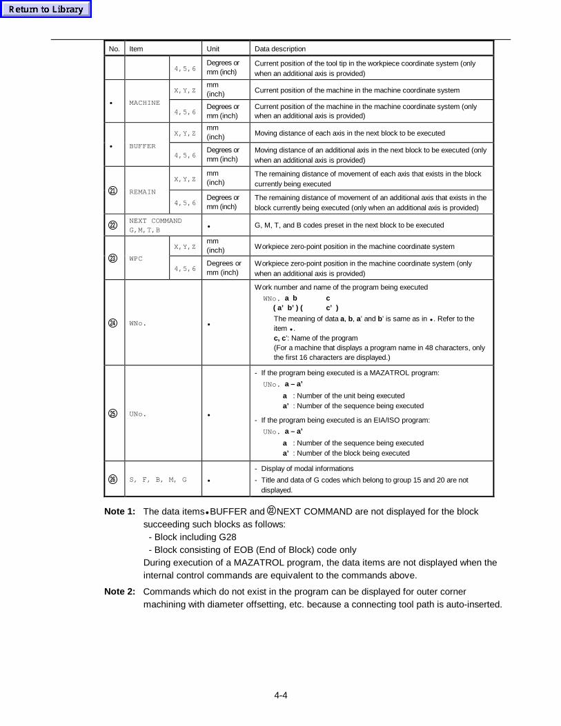
4-4
No. Item Unit Data description
4,5,6Degrees ormm (inch)
Current position of the tool tip in the workpiece coordinate system (onlywhen an additional axis is provided)
X,Y,Zmm(inch) Current position of the machine in the machine coordinate system
• MACHINE4,5,6
Degrees ormm (inch)
Current position of the machine in the machine coordinate system (onlywhen an additional axis is provided)
X,Y,Zmm(inch) Moving distance of each axis in the next block to be executed
• BUFFER4,5,6
Degrees ormm (inch)
Moving distance of an additional axis in the next block to be executed (onlywhen an additional axis is provided)
X,Y,Zmm(inch)
The remaining distance of movement of each axis that exists in the blockcurrently being executed
21 REMAIN
4,5,6Degrees ormm (inch)
The remaining distance of movement of an additional axis that exists in theblock currently being executed (only when an additional axis is provided)
22NEXT COMMANDG,M,T,B
• G, M, T, and B codes preset in the next block to be executed
X,Y,Zmm(inch) Workpiece zero-point position in the machine coordinate system
23 WPC
4,5,6Degrees ormm (inch)
Workpiece zero-point position in the machine coordinate system (onlywhen an additional axis is provided)
24 WNo. •
Work number and name of the program being executed
WNo. a b c ( a’ b’ ) ( c’ )
The meaning of data a, b, a’ and b’ is same as in • . Refer to theitem • .c, c ’: Name of the program(For a machine that displays a program name in 48 characters, onlythe first 16 characters are displayed.)
25 UNo. •
- If the program being executed is a MAZATROL program:
UNo. a – a’
a : Number of the unit being executeda’ : Number of the sequence being executed
- If the program being executed is an EIA/ISO program:
UNo. a – a’
a : Number of the sequence being executeda’ : Number of the block being executed
26 S, F, B, M, G •
- Display of modal informations
- Title and data of G codes which belong to group 15 and 20 are notdisplayed.
Note 1: The data items• BUFFER and 22 NEXT COMMAND are not displayed for the blocksucceeding such blocks as follows: - Block including G28 - Block consisting of EOB (End of Block) code onlyDuring execution of a MAZATROL program, the data items are not displayed when theinternal control commands are equivalent to the commands above.
Note 2: Commands which do not exist in the program can be displayed for outer cornermachining with diameter offsetting, etc. because a connecting tool path is auto-inserted.
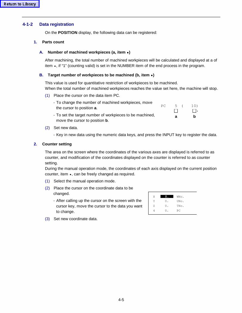
4-5
4-1-2 Data registration
On the POSITION display, the following data can be registered:
1. Parts count
A. Number of machined workpi eces (a, item • )
After machining, the total number of machined workpieces will be calculated and displayed at a ofitem • , if “1” (counting valid) is set in the NUMBER item of the end process in the program.
B. Target number of workpieces to be mac hined (b, item • )
This value is used for quantitative restriction of workpieces to be machined.When the total number of machined workpieces reaches the value set here, the machine will stop.
(1) Place the cursor on the data item PC.
- To change the number of machined workpieces, movethe cursor to position a.
- To set the target number of workpieces to be machined,move the cursor to position b.
PC 5 ( 10)
��
b��
a
(2) Set new data.
- Key in new data using the numeric data keys, and press the INPUT key to register the data.
2. Counter setting
The area on the screen where the coordinates of the various axes are displayed is referred to ascounter, and modification of the coordinates displayed on the counter is referred to as countersetting.During the manual operation mode, the coordinates of each axis displayed on the current positioncounter, item • , can be freely changed as required.
(1) Select the manual operation mode.
(2) Place the cursor on the coordinate data to bechanged.
- After calling up the cursor on the screen with thecursor key, move the cursor to the data you wantto change.
X 0. WNo.
Y 0. UNo.
Z 0. TNo.
4 0. PC
0.
(3) Set new coordinate data.
4-6
4-1-3 Display operations
1. Work number selection
Any of the work numbers displayed on the POSITION display (that is, the work numbers of theprograms which can be used for automatic operation) can be selected.The procedure is as follows:
(1) Press the WORK No. menu key.
Î The menu item changes to a reverse display status and a work number listing window isdisplayed.
(2) Set a work number.
Î The work number of the program which can be used for automatic operation will beselected.
2. Command display
Machine positions and modal information can be displayed. To check further details, see the itemin Subsection 4-1-1 Data display above.
(1) Press the COMMAND menu key.
Î The menu item changes to a reverse display status and commands are displayed.
- Pressing the menu key once again releases the reverse status of the menu item and createsthe normal display.
3. Shape drawing
The shape data in the selected program can be displayed in the window.See the Section, 2-4 Windows for further details.
4-2 TRACE Display
Function:
- This display can be used for displaying the operational status of machine in graphic form.
- This display is useful for displaying the tool movements synchronized with actual machine actionsincluding an ATC action.
- Machining shape and path of the tool tip can be displayed on this display. Even in the lockedstatus of machine, the movement of the tool indicated on this display will continue. The runningstatus of the machining program can therefore be checked without actually operating themachine.
Remarks:
- A plane to be used to display machining shape and path of the tool tip can be designated.
- Scale values used for machining shape display and the tool tip path display can be changed.
- Data of the machining shape can be stored.
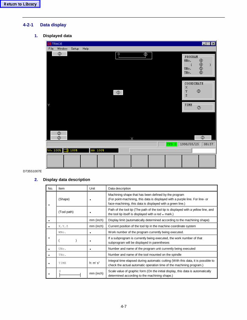
4-7
4-2-1 Data display
1. Displayed data
D735S1007E
2. Display data description
No. Item Unit Data description
(Shape) •
Machining shape that has been defined by the program(For point-machining, this data is displayed with a purple line. For line- orface-machining, this data is displayed with a green line.)•
(Tool path) •Path of the tool tip (The path of the tool tip is displayed with a yellow line, andthe tool tip itself is displayed with a red • mark.)
• mm (inch) Display limit (automatically determined according to the machining shape)
• X,Y,Z mm (inch) Current position of the tool tip in the machine coordinate system
WNo. • Work number of the program currently being executed.
•( ) •
If a subprogram is currently being executed, the work number of thatsubprogram will be displayed in parentheses
• UNo. • Number and name of the program unit currently being executed
• TNo. Number and name of the tool mounted on the spindle
• TIME h: m’ s”Integral time elapsed during automatic cutting (With this data, it is possible tocheck the actual automatic operation time of the machining program.)
•0
mm (inch)Scale value of graphic form (On the initial display, this data is automaticallydetermined according to the machining shape.)
4-8
4-1-2 Displaying machining shape and tool tip
(1) Press the WORK No. menu key
Î The display status of WORK No. will then be reversed.
(2) Press the numeric key(s) that corresponds to the work number of the program to be executed,and then press the INPUT key.
Î The input work number will then be displayed in the WNo. item (date portion • ) and thereverse-display status of WORK No. will be cleared.
(3) Press the PART SHAPE menu key.
Î This will cause the display status of PART SHAPE to reverse and the machining shapesto be displayed continuously. After displaying the machining shapes, the reverse-displaystatus of PART SHAPE will be cleared.
Note 1: If procedure described in Subsection 4-2-3 Plane select below is carried out, then itbecomes possible to select the plane or 3-D view on which machining shapes are to bedisplayed.If no steps of this procedure are carried out, the machining shape available on the XYplane will be displayed.
Note 2: If procedure described in Subsection 4-2-4 Change of scale values described below iscarried out, it becomes possible for available machining shapes to be displayed inenlarged or reduced size.If no steps of this procedure are carried out, the available machining shapes will bedisplayed with the scaling factor which has been automatically determined.
(4) Press the CYCLE START button.
Î The lamp of the CYCLE START button will light up and the path of the tool tip (markedwith • ) synchronized with the machine action will be displayed.
- After the entire path of the tool tip has been displayed (i.e., after execution of the programhas been completed), the lamp of the CYCLE START button will go out.
Note 1: The machining shape that has been displayed in procedural step (3) above can be erasedby pressing the SHAPE ERASE menu key.
Note 2: The path of the tool tip can be erased by pressing the PATH ERASE menu key.
Note 3: If STORE is displayed reversely by depression of the STORE menu key, the shape datawill be preserved permanently to prevent its destruction due to display changeover.
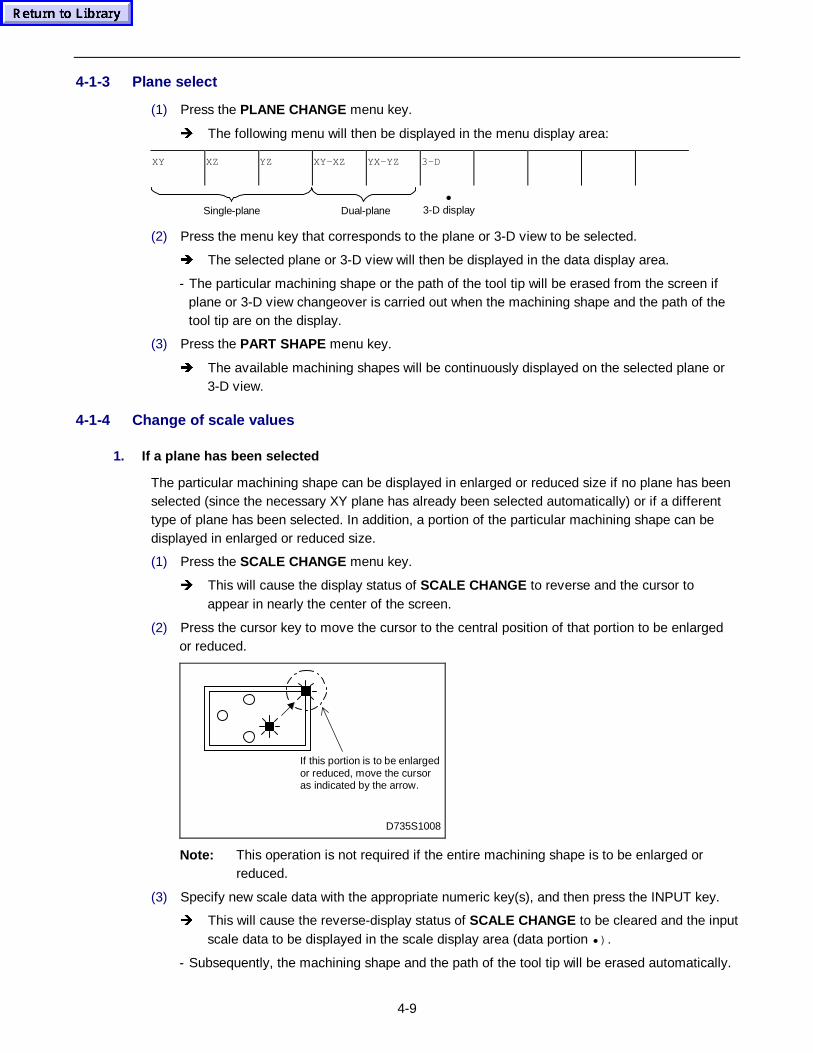
4-9
4-1-3 Plane select
(1) Press the PLANE CHANGE menu key.
Î The following menu will then be displayed in the menu display area:
XY XZ YZ XY-XZ YX-YZ 3-D
(2) Press the menu key that corresponds to the plane or 3-D view to be selected.
Î The selected plane or 3-D view will then be displayed in the data display area.
- The particular machining shape or the path of the tool tip will be erased from the screen ifplane or 3-D view changeover is carried out when the machining shape and the path of thetool tip are on the display.
(3) Press the PART SHAPE menu key.
Î The available machining shapes will be continuously displayed on the selected plane or3-D view.
4-1-4 Change of scale values
1. If a plane has been selected
The particular machining shape can be displayed in enlarged or reduced size if no plane has beenselected (since the necessary XY plane has already been selected automatically) or if a differenttype of plane has been selected. In addition, a portion of the particular machining shape can bedisplayed in enlarged or reduced size.
(1) Press the SCALE CHANGE menu key.
Î This will cause the display status of SCALE CHANGE to reverse and the cursor toappear in nearly the center of the screen.
(2) Press the cursor key to move the cursor to the central position of that portion to be enlargedor reduced.
D735S1008
If this portion is to be enlargedor reduced, move the cursoras indicated by the arrow.
Note: This operation is not required if the entire machining shape is to be enlarged orreduced.
(3) Specify new scale data with the appropriate numeric key(s), and then press the INPUT key.
Î This will cause the reverse-display status of SCALE CHANGE to be cleared and the inputscale data to be displayed in the scale display area (data portion •) .
- Subsequently, the machining shape and the path of the tool tip will be erased automatically.
•3-D displayDual-planeSingle-plane
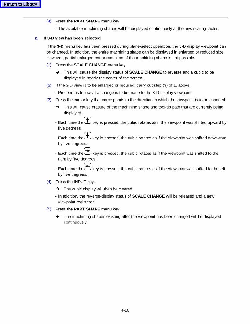
4-10
(4) Press the PART SHAPE menu key.
- The available machining shapes will be displayed continuously at the new scaling factor.
2. If 3-D view has been selected
If the 3-D menu key has been pressed during plane-select operation, the 3-D display viewpoint canbe changed. In addition, the entire machining shape can be displayed in enlarged or reduced size.However, partial enlargement or reduction of the machining shape is not possible.
(1) Press the SCALE CHANGE menu key.
Î This will cause the display status of SCALE CHANGE to reverse and a cubic to bedisplayed in nearly the center of the screen.
(2) If the 3-D view is to be enlarged or reduced, carry out step (3) of 1. above.
- Proceed as follows if a change is to be made to the 3-D display viewpoint.
(3) Press the cursor key that corresponds to the direction in which the viewpoint is to be changed.
Î This will cause erasure of the machining shape and tool-tip path that are currently beingdisplayed.
- Each time the key is pressed, the cubic rotates as if the viewpoint was shifted upward byfive degrees.
- Each time the key is pressed, the cubic rotates as if the viewpoint was shifted downwardby five degrees.
- Each time the key is pressed, the cubic rotates as if the viewpoint was shifted to theright by five degrees.
- Each time the key is pressed, the cubic rotates as if the viewpoint was shifted to the leftby five degrees.
(4) Press the INPUT key.
Î The cubic display will then be cleared.
- In addition, the reverse-display status of SCALE CHANGE will be released and a newviewpoint registered.
(5) Press the PART SHAPE menu key.
Î The machining shapes existing after the viewpoint has been changed will be displayedcontinuously.
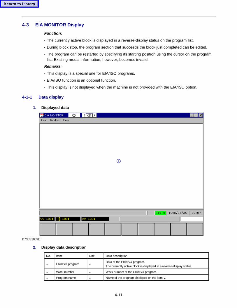
4-11
4-3 EIA MONITOR Display
Function:
- The currently active block is displayed in a reverse-display status on the program list.
- During block stop, the program section that succeeds the block just completed can be edited.
- The program can be restarted by specifying its starting position using the cursor on the programlist. Existing modal information, however, becomes invalid.
Remarks:
- This display is a special one for EIA/ISO programs.
- EIA/ISO function is an optional function.
- This display is not displayed when the machine is not provided with the EIA/ISO option.
4-1-1 Data display
1. Displayed data
D735S1009E
2. Display data description
No. Item Unit Data description
• EIA/ISO program •Data of the EIA/ISO program.The currently active block is displayed in a reverse-display status.
• Work number • Work number of the EIA/ISO program.
• Program name • Name of the program displayed on the item • .
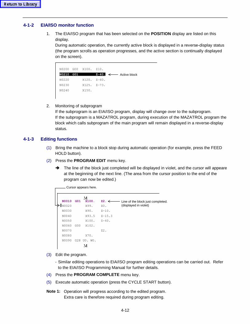
4-12
4-1-2 EIA/ISO monitor function
1. The EIA/ISO program that has been selected on the POSITION display are listed on thisdisplay.During automatic operation, the currently active block is displayed in a reverse-display status(the program scrolls as operation progresses, and the active section is continually displayedon the screen).
N0200 G00 X100. Z10.
N0210 G01 Z-40.
N0220 X120. Z-60.
N0230 X125. Z-73.
N0240 X150.
Active block
2. Monitoring of subprogramIf the subprogram is an EIA/ISO program, display will change over to the subprogram.If the subprogram is a MAZATROL program, during execution of the MAZATROL program theblock which calls subprogram of the main program will remain displayed in a reverse-displaystatus.
4-1-3 Editing functions
(1) Bring the machine to a block stop during automatic operation (for example, press the FEEDHOLD button).
(2) Press the PROGRAM EDIT menu key.
Î The line of the block just completed will be displayed in violet, and the cursor will appeareat the beginning of the next line. (The area from the cursor position to the end of theprogram can now be edited.)
0N0010 G01 X100. Z2.
N0020 X99. Z0.
N0030 X90. Z-10.
N0040 X93.5 Z-15.3
N0050 X100. Z-40.
N0060 G00 X102.
N0070 Z2.
N0080 X70.
N0090 G28 U0. W0.
0
Line of the block just completed.(displayed in violet)
Cursor appears here.
(3) Edit the program.
- Similar editing operations to EIA/ISO program editing operations can be carried out. Referto the EIA/ISO Programming Manual for further details.
(4) Press the PROGRAM COMPLETE menu key.
(5) Execute automatic operation (press the CYCLE START button).
Note 1: Operation will progress according to the edited program.Extra care is therefore required during program editing.
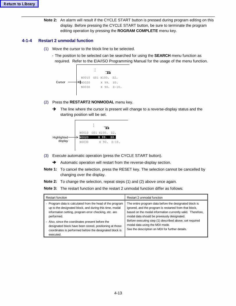
4-13
Note 2: An alarm will result if the CYCLE START button is pressed during program editing on thisdisplay. Before pressing the CYCLE START button, be sure to terminate the programediting operation by pressing the ROGRAM COMPLETE menu key.
4-1-4 Restart 2 unmodal function
(1) Move the cursor to the block line to be selected.
- The position to be selected can be searched for using the SEARCH menu function asrequired. Refer to the EIA/ISO Programming Manual for the usage of the menu function.
�#�#
N0010 G01 X100. Z2.
N0020 X 99. Z0.
N0030 X 90. Z-10.
Cursor
…
(2) Press the RESTART2 NONMODAL menu key.
Î The line where the cursor is present will change to a reverse-display status and thestarting position will be set.
�#�#
N0010 G01 X100. Z2.
N0020 X 99. Z0.
N0030 X 90. Z-10.
Highlighteddisplay
…
(3) Execute automatic operation (press the CYCLE START button).
Î Automatic operation will restart from the reverse-display section.
Note 1: To cancel the selection, press the RESET key. The selection cannot be cancelled bychanging over the display.
Note 2: To change the selection, repeat steps (1) and (2) above once again.
Note 3: The restart function and the restart 2 unmodal function differ as follows:
Restart function Restart 2 unmodal function
- Program data is calculated from the head of the programup to the designated block, and during this time, modalinformation setting, program error checking, etc. areperformed.
- Also, since the coordinates present before thedesignated block have been stored, positioning at thosecoordinates is performed before the designated block isexecuted.
The entire program data before the designated block isignored, and the program is restarted from that block,based on the modal information currently valid. Therefore,modal data should be previously designated.Before executing step (1) described above, set requiredmodal data using the MDI mode.See the description on MDI for further details.
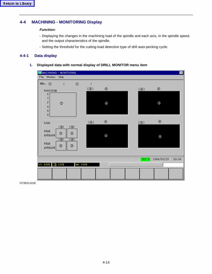
4-14
4-4 MACHINING - MONITORING Display
Function:
- Displaying the changes in the machining load of the spindle and each axis, in the spindle speed,and the output characteristics of the spindle.
- Setting the threshold for the cutting-load detection type of drill auto-pecking cycle.
4-4-1 Data display
1. Displayed data with normal display of DR ILL MONITOR menu item
D735S1101E
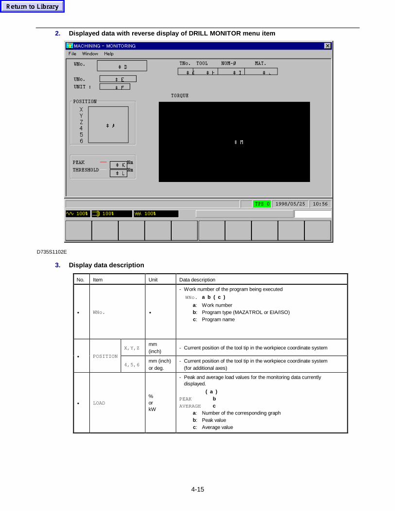
4-15
2. Displayed data with reverse display of DR ILL MONITOR menu item
 0
 $
 /
 .
 +  - , *
 )
 (
 '
D735S1102E
3. Display data description
No. Item Unit Data description
• WNo. •
- Work number of the program being executed
WNo. a b ( c )
a: Work numberb: Program type (MAZATROL or EIA/ISO)c: Program name
X,Y,Zmm(inch)
- Current position of the tool tip in the workpiece coordinate system
• POSITION
4,5,6mm (inch)or deg.
- Current position of the tool tip in the workpiece coordinate system(for additional axes)
• LOAD%orkW
- Peak and average load values for the monitoring data currentlydisplayed.
( a ) PEAK b AVERAGE c
a: Number of the corresponding graphb: Peak valuec: Average value
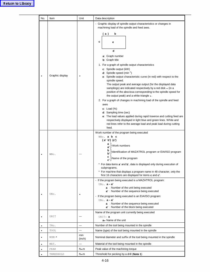
4-16
No. Item Unit Data description
• Graphic display •
- Graphic display of spindle output characteristics or changes inmachining load of the spindle and feed axes.
e
d
c
( a ) b
a: Graph numberb: Graph title
1. For a graph of spindle output characteristics
c: Spindle output (kW)d: Spindle speed (min–1)e: Spindle output characteristic curve (in red) with respect to the
spindle speed.The output peak and average output (for the displayed datasamplings) are indicated respectively by a red disk • (in aposition of the abscissa corresponding to the spindle speed forthe output peak) and a white triangle • .
2. For a graph of changes in machining load of the spindle and feed
axes
c: Load (%)d: Sampling time (sec)e: The load values applied during rapid traverse and cutting feed are
respectively displayed in light blue and green lines. White andred lines refer to the average load and peak load during cuttingfeed.
• WNo. —
Work number of the program being executed
WNo. a b c ( a’ b’) (c’)
Work numbers
Identification of MAZATROL program or EIA/ISO program
aa’bb’cc’
Name of the program
* For data items a’ and b’, data is displayed only during execution ofsubprograms.
* For machine that displays a program name in 48 character, only thefirst 16 characters are displayed for items c and c’ .
• UNo. •
- If the program being executed is a MAZATROL program:UNo. a – a’
a : Number of the unit being executeda’ : Number of the sequence being executed
- If the program being executed is an EIA/ISO program:UNo. a – a’
a : Number of the sequence being executeda’ : Number of the block being executed
• UNIT —
Name of the program unit currently being executed
UNIT: aa• Name of the unit
• TNo. — Number of the tool being mounted in the spindle
• TOOL — Name (type) of the tool being mounted in the spindle
• NOM-•mm(inch) Nominal diameter and suffix of the tool being mounted in the spindle
• MAT. — Material of the tool being mounted in the spindle
• PEAK N• m Peak value of the machining torque
• THRESHOLD N• m Threshold for pecking by a drill (Note 1 )
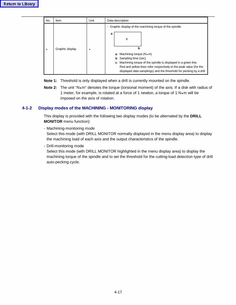
4-17
No. Item Unit Data description
• Graphic display •
- Graphic display of the machining torque of the spindle.
a
c
b
a: Machining torque (N• m)b: Sampling time (sec)c: Machining torque of the spindle is displayed in a green line.
Red and yellow lines refer respectively to the peak value (for thedisplayed data samplings) and the threshold for pecking by a drill.
Note 1: Threshold is only displayed when a drill is currently mounted on the spindle.
Note 2: The unit “N• m” denotes the torque (torsional moment) of the axis. If a disk with radius of1 meter, for example, is rotated at a force of 1 newton, a torque of 1 N• m will beimposed on the axis of rotation.
4-1-2 Display modes of the MACHINING - MONITORING display
This display is provided with the following two display modes (to be alternated by the DRILLMONITOR menu function):
- Machining-monitoring modeSelect this mode (with DRILL MONITOR normally displayed in the menu display area) to displaythe machining load of each axis and the output characteristics of the spindle.
- Drill-monitoring modeSelect this mode (with DRILL MONITOR highlighted in the menu display area) to display themachining torque of the spindle and to set the threshold for the cutting-load detection type of drillauto-pecking cycle.
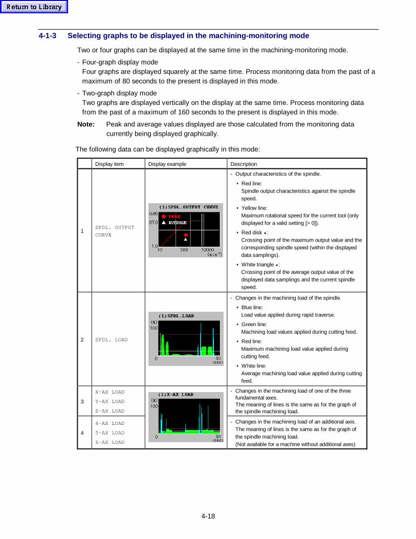
4-18
4-1-3 Selecting graphs to be displayed in the machining-monitoring mode
Two or four graphs can be displayed at the same time in the machining-monitoring mode.
- Four-graph display modeFour graphs are displayed squarely at the same time. Process monitoring data from the past of amaximum of 80 seconds to the present is displayed in this mode.
- Two-graph display modeTwo graphs are displayed vertically on the display at the same time. Process monitoring datafrom the past of a maximum of 160 seconds to the present is displayed in this mode.
Note: Peak and average values displayed are those calculated from the monitoring datacurrently being displayed graphically.
The following data can be displayed graphically in this mode:
Display item Display example Description
1SPDL. OUTPUT
CURVE
- Output characteristics of the spindle.
• Red line:Spindle output characteristics against the spindlespeed.
• Yellow line:Maximum rotational speed for the current tool (onlydisplayed for a valid setting [> 0]).
• Red disk • :Crossing point of the maximum output value and thecorresponding spindle speed (within the displayeddata samplings).
• White triangle • :Crossing point of the average output value of thedisplayed data samplings and the current spindlespeed.
2 SPDL. LOAD
- Changes in the machining load of the spindle.
• Blue line:Load value applied during rapid traverse.
• Green line:Machining load values applied during cutting feed.
• Red line:Maximum machining load value applied duringcutting feed.
• White line:Average machining load value applied during cuttingfeed.
3
X-AX LOAD
Y-AX LOAD
Z-AX LOAD
- Changes in the machining load of one of the threefundamental axes.The meaning of lines is the same as for the graph ofthe spindle machining load.
4
4-AX LOAD
5-AX LOAD
6-AX LOAD
- Changes in the machining load of an additional axis.The meaning of lines is the same as for the graph ofthe spindle machining load.(Not available for a machine without additional axes)
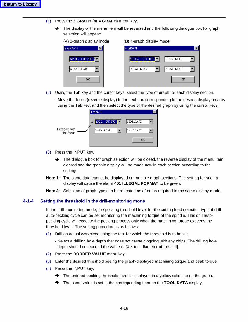
4-19
(1) Press the 2 GRAPH (or 4 GRAPH) menu key.
Î The display of the menu item will be reversed and the following dialogue box for graphselection will appear:
(A) 2-graph display mode (B) 4-graph display mode
(2) Using the Tab key and the cursor keys, select the type of graph for each display section.
- Move the focus (reverse display) to the text box corresponding to the desired display area byusing the Tab key, and then select the type of the desired graph by using the cursor keys.
Text box withthe focus
(3) Press the INPUT key.
Î The dialogue box for graph selection will be closed, the reverse display of the menu itemcleared and the graphic display will be made now in each section according to thesettings.
Note 1: The same data cannot be displayed on multiple graph sections. The setting for such adisplay will cause the alarm 401 ILLEGAL FORMAT to be given.
Note 2: Selection of graph type can be repeated as often as required in the same display mode.
4-1-4 Setting the threshold in the drill-monitoring mode
In the drill-monitoring mode, the pecking threshold level for the cutting-load detection type of drillauto-pecking cycle can be set monitoring the machining torque of the spindle. This drill auto-pecking cycle will execute the pecking process only when the machining torque exceeds thethreshold level. The setting procedure is as follows:
(1) Drill an actual workpiece using the tool for which the threshold is to be set.
- Select a drilling hole depth that does not cause clogging with any chips. The drilling holedepth should not exceed the value of [3 × tool diameter of the drill].
(2) Press the BORDER VALUE menu key.
(3) Enter the desired threshold seeing the graph-displayed machining torque and peak torque.
(4) Press the INPUT key.
Î The entered pecking threshold level is displayed in a yellow solid line on the graph.
Î The same value is set in the corresponding item on the TOOL DATA display.
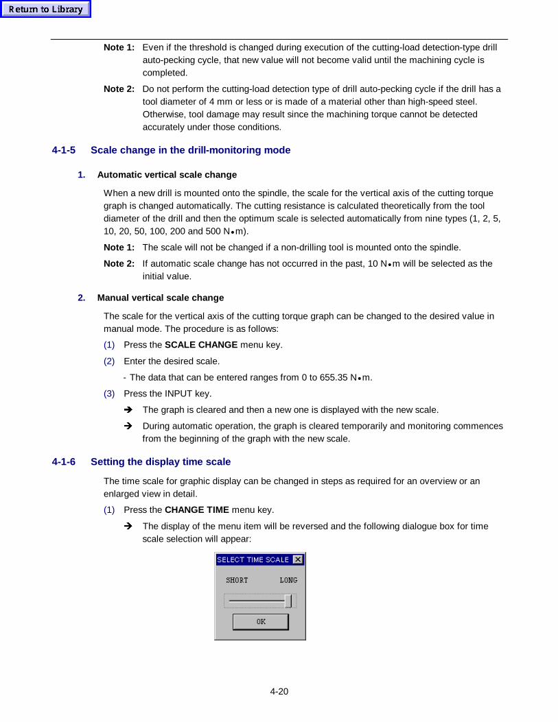
4-20
Note 1: Even if the threshold is changed during execution of the cutting-load detection-type drillauto-pecking cycle, that new value will not become valid until the machining cycle iscompleted.
Note 2: Do not perform the cutting-load detection type of drill auto-pecking cycle if the drill has atool diameter of 4 mm or less or is made of a material other than high-speed steel.Otherwise, tool damage may result since the machining torque cannot be detectedaccurately under those conditions.
4-1-5 Scale change in the drill-monitoring mode
1. Automatic vertical scale change
When a new drill is mounted onto the spindle, the scale for the vertical axis of the cutting torquegraph is changed automatically. The cutting resistance is calculated theoretically from the tooldiameter of the drill and then the optimum scale is selected automatically from nine types (1, 2, 5,10, 20, 50, 100, 200 and 500 N• m).
Note 1: The scale will not be changed if a non-drilling tool is mounted onto the spindle.
Note 2: If automatic scale change has not occurred in the past, 10 N• m will be selected as theinitial value.
2. Manual vertical scale change
The scale for the vertical axis of the cutting torque graph can be changed to the desired value inmanual mode. The procedure is as follows:
(1) Press the SCALE CHANGE menu key.
(2) Enter the desired scale.
- The data that can be entered ranges from 0 to 655.35 N• m.
(3) Press the INPUT key.
Î The graph is cleared and then a new one is displayed with the new scale.
Î During automatic operation, the graph is cleared temporarily and monitoring commencesfrom the beginning of the graph with the new scale.
4-1-6 Setting the display time scale
The time scale for graphic display can be changed in steps as required for an overview or anenlarged view in detail.
(1) Press the CHANGE TIME menu key.
Î The display of the menu item will be reversed and the following dialogue box for timescale selection will appear:
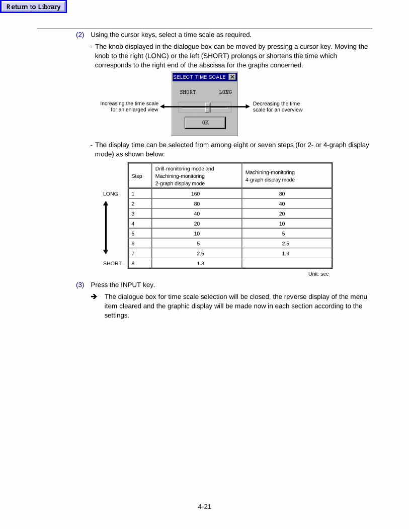
4-21
(2) Using the cursor keys, select a time scale as required.
- The knob displayed in the dialogue box can be moved by pressing a cursor key. Moving theknob to the right (LONG) or the left (SHORT) prolongs or shortens the time whichcorresponds to the right end of the abscissa for the graphs concerned.
Decreasing the timescale for an overview
Increasing the time scalefor an enlarged view
- The display time can be selected from among eight or seven steps (for 2- or 4-graph displaymode) as shown below:
StepDrill-monitoring mode andMachining-monitoring2-graph display mode
Machining-monitoring4-graph display mode
LONG 1 160 80
2 80 40
3 40 20
4 20 10
5 10 5
6 5 2.5
7 2.5 1.3
SHORT 8 1.3
Unit: sec
(3) Press the INPUT key.
Î The dialogue box for time scale selection will be closed, the reverse display of the menuitem cleared and the graphic display will be made now in each section according to thesettings.

4-22
- NOTE -
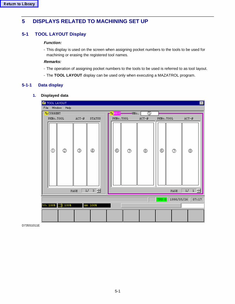
5-1
5 DISPLAYS RELATED TO MACHINING SET UP
5-1 TOOL LAYOUT Display
Function:
- This display is used on the screen when assigning pocket numbers to the tools to be used formachining or erasing the registered tool names.
Remarks:
- The operation of assigning pocket numbers to the tools to be used is referred to as tool layout.
- The TOOL LAYOUT display can be used only when executing a MAZATROL program.
5-1-1 Data display
1. Displayed data
D735S1011E
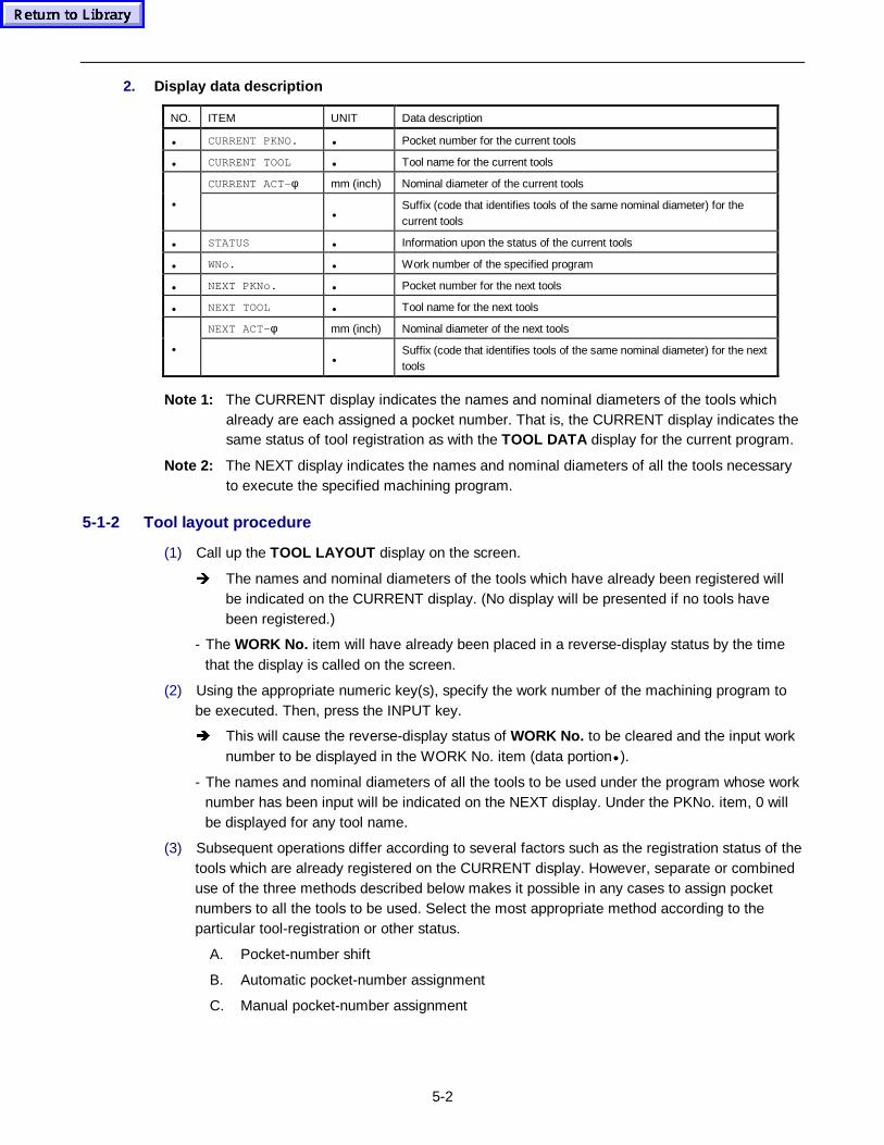
5-2
2. Display data description
NO. ITEM UNIT Data description
• CURRENT PKNO. • Pocket number for the current tools
• CURRENT TOOL • Tool name for the current tools
CURRENT ACT-φ mm (inch) Nominal diameter of the current tools
••
Suffix (code that identifies tools of the same nominal diameter) for thecurrent tools
• STATUS • Information upon the status of the current tools
• WNo. • Work number of the specified program
• NEXT PKNo. • Pocket number for the next tools
• NEXT TOOL • Tool name for the next tools
NEXT ACT-φ mm (inch) Nominal diameter of the next tools
••
Suffix (code that identifies tools of the same nominal diameter) for the nexttools
Note 1: The CURRENT display indicates the names and nominal diameters of the tools whichalready are each assigned a pocket number. That is, the CURRENT display indicates thesame status of tool registration as with the TOOL DATA display for the current program.
Note 2: The NEXT display indicates the names and nominal diameters of all the tools necessaryto execute the specified machining program.
5-1-2 Tool layout procedure
(1) Call up the TOOL LAYOUT display on the screen.
Î The names and nominal diameters of the tools which have already been registered willbe indicated on the CURRENT display. (No display will be presented if no tools havebeen registered.)
- The WORK No. item will have already been placed in a reverse-display status by the timethat the display is called on the screen.
(2) Using the appropriate numeric key(s), specify the work number of the machining program tobe executed. Then, press the INPUT key.
Î This will cause the reverse-display status of WORK No. to be cleared and the input worknumber to be displayed in the WORK No. item (data portion• ).
- The names and nominal diameters of all the tools to be used under the program whose worknumber has been input will be indicated on the NEXT display. Under the PKNo. item, 0 willbe displayed for any tool name.
(3) Subsequent operations differ according to several factors such as the registration status of thetools which are already registered on the CURRENT display. However, separate or combineduse of the three methods described below makes it possible in any cases to assign pocketnumbers to all the tools to be used. Select the most appropriate method according to theparticular tool-registration or other status.
A. Pocket-number shift
B. Automatic pocket-number assignment
C. Manual pocket-number assignment
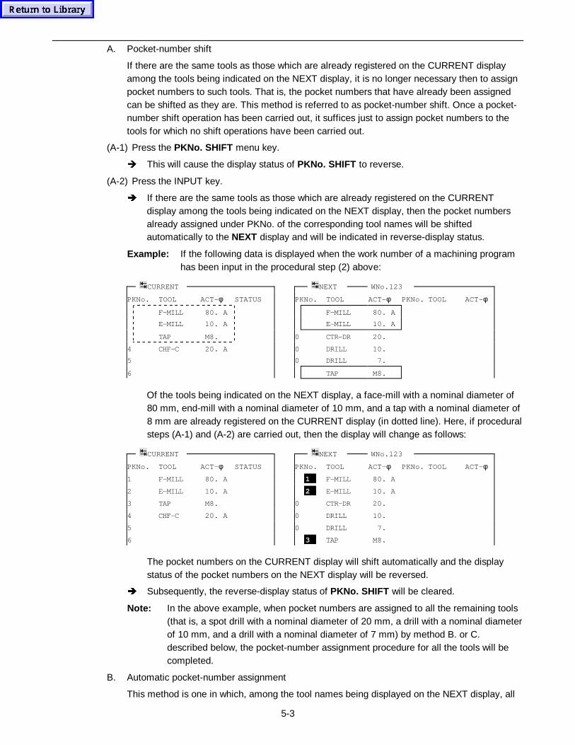
5-3
A. Pocket-number shift
If there are the same tools as those which are already registered on the CURRENT displayamong the tools being indicated on the NEXT display, it is no longer necessary then to assignpocket numbers to such tools. That is, the pocket numbers that have already been assignedcan be shifted as they are. This method is referred to as pocket-number shift. Once a pocket-number shift operation has been carried out, it suffices just to assign pocket numbers to thetools for which no shift operations have been carried out.
(A-1) Press the PKNo. SHIFT menu key.
Î This will cause the display status of PKNo. SHIFT to reverse.
(A-2) Press the INPUT key.
Î If there are the same tools as those which are already registered on the CURRENTdisplay among the tools being indicated on the NEXT display, then the pocket numbersalready assigned under PKNo. of the corresponding tool names will be shiftedautomatically to the NEXT display and will be indicated in reverse-display status.
Example: If the following data is displayed when the work number of a machining programhas been input in the procedural step (2) above:
CURRENT NEXT WNo.123
PKNo. TOOL ACT-φ STATUS PKNo. TOOL ACT-φ PKNo. TOOL ACT-φ
F-MILL 80. A F-MILL 80. A
E-MILL 10. A E-MILL 10. A
TAP M8. 0 CTR-DR 20.
4 CHF-C 20. A 0 DRILL 10.
5 0 DRILL 7.
6 TAP M8.
Of the tools being indicated on the NEXT display, a face-mill with a nominal diameter of80 mm, end-mill with a nominal diameter of 10 mm, and a tap with a nominal diameter of8 mm are already registered on the CURRENT display (in dotted line). Here, if proceduralsteps (A-1) and (A-2) are carried out, then the display will change as follows:
CURRENT NEXT WNo.123
PKNo. TOOL ACT-φ STATUS PKNo. TOOL ACT-φ PKNo. TOOL ACT-φ
1 F-MILL 80. A 1 F-MILL 80. A
2 E-MILL 10. A 2 E-MILL 10. A
3 TAP M8. 0 CTR-DR 20.
4 CHF-C 20. A 0 DRILL 10.
5 0 DRILL 7.
6 3 TAP M8.
The pocket numbers on the CURRENT display will shift automatically and the displaystatus of the pocket numbers on the NEXT display will be reversed.
Î Subsequently, the reverse-display status of PKNo. SHIFT will be cleared.
Note: In the above example, when pocket numbers are assigned to all the remaining tools(that is, a spot drill with a nominal diameter of 20 mm, a drill with a nominal diameterof 10 mm, and a drill with a nominal diameter of 7 mm) by method B. or C.described below, the pocket-number assignment procedure for all the tools will becompleted.
B. Automatic pocket-number assignment
This method is one in which, among the tool names being displayed on the NEXT display, all
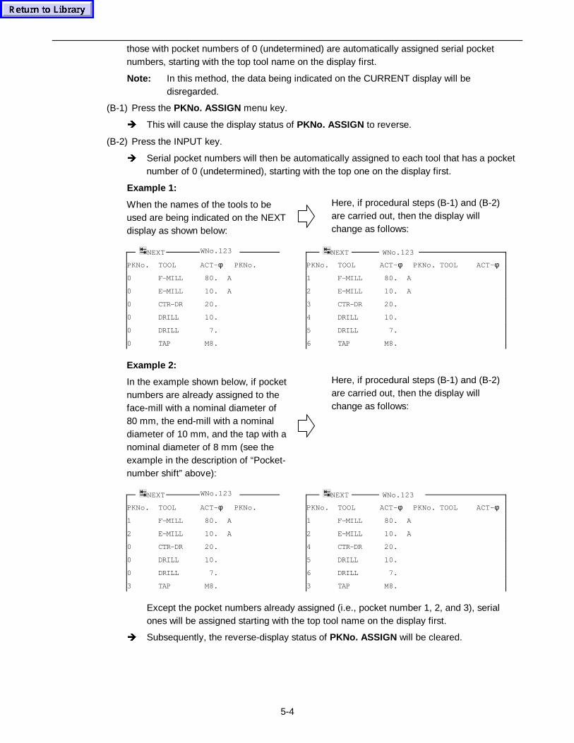
5-4
those with pocket numbers of 0 (undetermined) are automatically assigned serial pocketnumbers, starting with the top tool name on the display first.
Note: In this method, the data being indicated on the CURRENT display will bedisregarded.
(B-1) Press the PKNo. ASSIGN menu key.
Î This will cause the display status of PKNo. ASSIGN to reverse.
(B-2) Press the INPUT key.
Î Serial pocket numbers will then be automatically assigned to each tool that has a pocketnumber of 0 (undetermined), starting with the top one on the display first.
Example 1:
When the names of the tools to beused are being indicated on the NEXTdisplay as shown below:
Here, if procedural steps (B-1) and (B-2)are carried out, then the display willchange as follows:
NEXT WNo.123 NEXT WNo.123
PKNo. TOOL ACT-φ PKNo. PKNo. TOOL ACT-φ PKNo. TOOL ACT-φ
0 F-MILL 80. A 1 F-MILL 80. A
0 E-MILL 10. A 2 E-MILL 10. A
0 CTR-DR 20. 3 CTR-DR 20.
0 DRILL 10. 4 DRILL 10.
0 DRILL 7. 5 DRILL 7.
0 TAP M8. 6 TAP M8.
Example 2:
In the example shown below, if pocketnumbers are already assigned to theface-mill with a nominal diameter of80 mm, the end-mill with a nominaldiameter of 10 mm, and the tap with anominal diameter of 8 mm (see theexample in the description of “Pocket-number shift” above):
Here, if procedural steps (B-1) and (B-2)are carried out, then the display willchange as follows:
NEXT WNo.123 NEXT WNo.123
PKNo. TOOL ACT-φ PKNo. PKNo. TOOL ACT-φ PKNo. TOOL ACT-φ
1 F-MILL 80. A 1 F-MILL 80. A
2 E-MILL 10. A 2 E-MILL 10. A
0 CTR-DR 20. 4 CTR-DR 20.
0 DRILL 10. 5 DRILL 10.
0 DRILL 7. 6 DRILL 7.
3 TAP M8. 3 TAP M8.
Except the pocket numbers already assigned (i.e., pocket number 1, 2, and 3), serialones will be assigned starting with the top tool name on the display first.
Î Subsequently, the reverse-display status of PKNo. ASSIGN will be cleared.
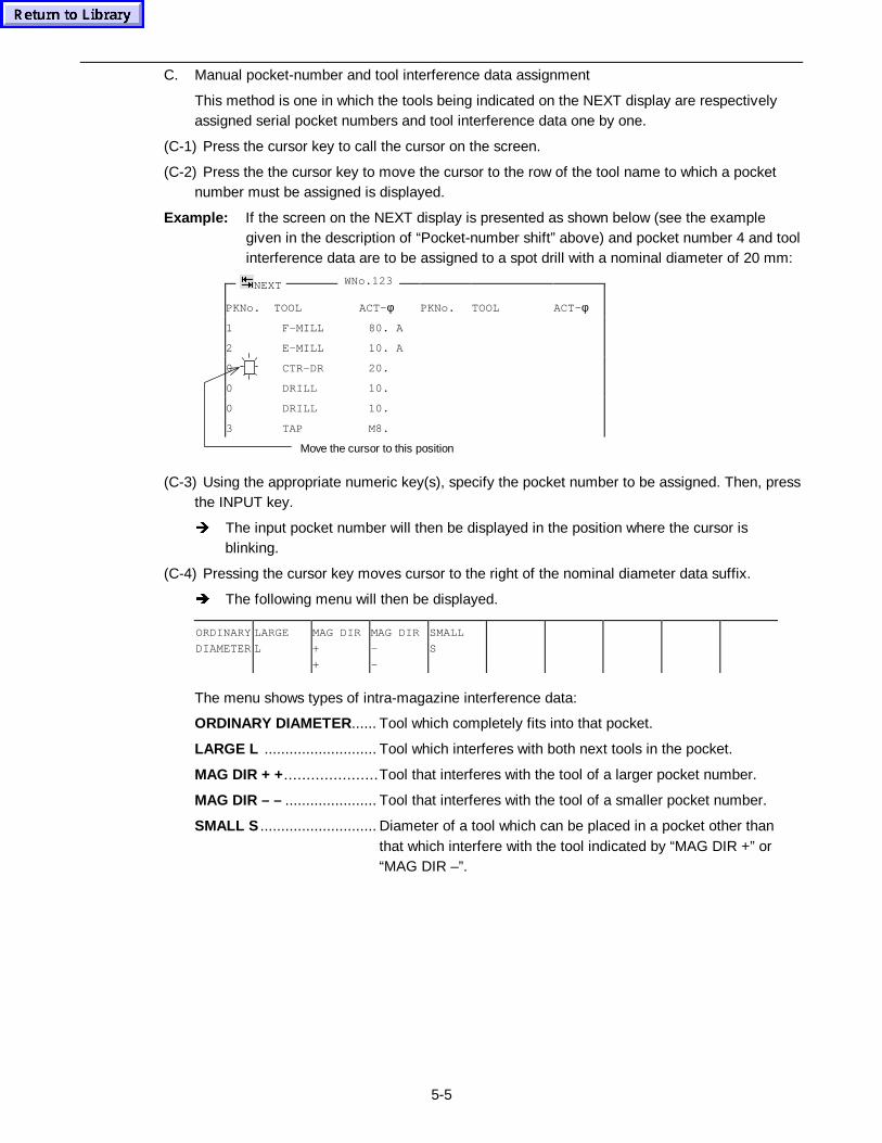
5-5
C. Manual pocket-number and tool interference data assignment
This method is one in which the tools being indicated on the NEXT display are respectivelyassigned serial pocket numbers and tool interference data one by one.
(C-1) Press the cursor key to call the cursor on the screen.
(C-2) Press the the cursor key to move the cursor to the row of the tool name to which a pocketnumber must be assigned is displayed.
Example: If the screen on the NEXT display is presented as shown below (see the examplegiven in the description of “Pocket-number shift” above) and pocket number 4 and toolinterference data are to be assigned to a spot drill with a nominal diameter of 20 mm:
PKNo. TOOL ACT-φ PKNo. TOOL ACT-φ
1 F-MILL 80. A
2 E-MILL 10. A
0 CTR-DR 20.
0 DRILL 10.
0 DRILL 10.
3 TAP M8.
Move the cursor to this position
(C-3) Using the appropriate numeric key(s), specify the pocket number to be assigned. Then, pressthe INPUT key.
Î The input pocket number will then be displayed in the position where the cursor isblinking.
(C-4) Pressing the cursor key moves cursor to the right of the nominal diameter data suffix.
Î The following menu will then be displayed.
ORDINARY
DIAMETER
LARGE
L
MAG DIR
+
+
MAG DIR
-
-
SMALL
S
The menu shows types of intra-magazine interference data:
ORDINARY DIAMETER ...... Tool which completely fits into that pocket.
LARGE L ........................... Tool which interferes with both next tools in the pocket.
MAG DIR + + .....................Tool that interferes with the tool of a larger pocket number.
MAG DIR – – ...................... Tool that interferes with the tool of a smaller pocket number.
SMALL S ............................ Diameter of a tool which can be placed in a pocket other thanthat which interfere with the tool indicated by “MAG DIR +” or“MAG DIR –”.
NEXT WNo.123
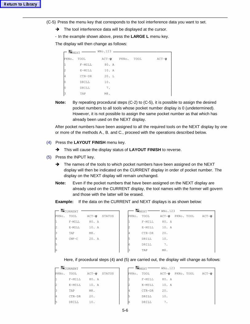
5-6
(C-5) Press the menu key that corresponds to the tool interference data you want to set.
Î The tool interference data will be displayed at the cursor.
- In the example shown above, press the LARGE L menu key.
The display will then change as follows:
PKNo. TOOL ACT-φ PKNo. TOOL ACT-φ
1 F-MILL 80. A
2 E-MILL 10. A
4 CTR-DR 20. L
0 DRILL 10.
0 DRILL 7.
3 TAP M8.
Note: By repeating procedural steps (C-2) to (C-5), it is possible to assign the desiredpocket numbers to all tools whose pocket number display is 0 (undetermined).However, it is not possible to assign the same pocket number as that which hasalready been used on the NEXT display.
After pocket numbers have been assigned to all the required tools on the NEXT display by oneor more of the methods A., B. and C., proceed with the operations described below.
(4) Press the LAYOUT FINISH menu key.
Î This will cause the display status of LAYOUT FINISH to reverse.
(5) Press the INPUT key.
Î The names of the tools to which pocket numbers have been assigned on the NEXTdisplay will then be indicated on the CURRENT display in order of pocket number. Thedisplay on the NEXT display will remain unchanged.
Note: Even if the pocket numbers that have been assigned on the NEXT display arealready used on the CURRENT display, the tool names with the former will governand those with the latter will be erased.
Example: If the data on the CURRENT and NEXT displays is as shown below:
CURRENT NEXT WNo.123
PKNo. TOOL ACT-φ STATUS PKNo. TOOL ACT-φ PKNo. TOOL ACT-φ
1 F-MILL 80. A 1 F-MILL 80. A
2 E-MILL 10. A 2 E-MILL 10. A
3 TAP M8. 4 CTR-DR 20.
4 CHF-C 20. A 5 DRILL 10.
5 6 DRILL 7.
6 3 TAP M8.
Here, if procedural steps (4) and (5) are carried out, the display will change as follows:
CURRENT NEXT WNo.123
PKNo. TOOL ACT-φ STATUS PKNo. TOOL ACT-φ PKNo. TOOL ACT-φ
1 F-MILL 80. A 1 F-MILL 80. A
2 E-MILL 10. A 2 E-MILL 10. A
3 TAP M8. 4 CTR-DR 20.
4 CTR-DR 20. 5 DRILL 10.
5 DRILL 10. 6 DRILL 7.
NEXT WNo.123
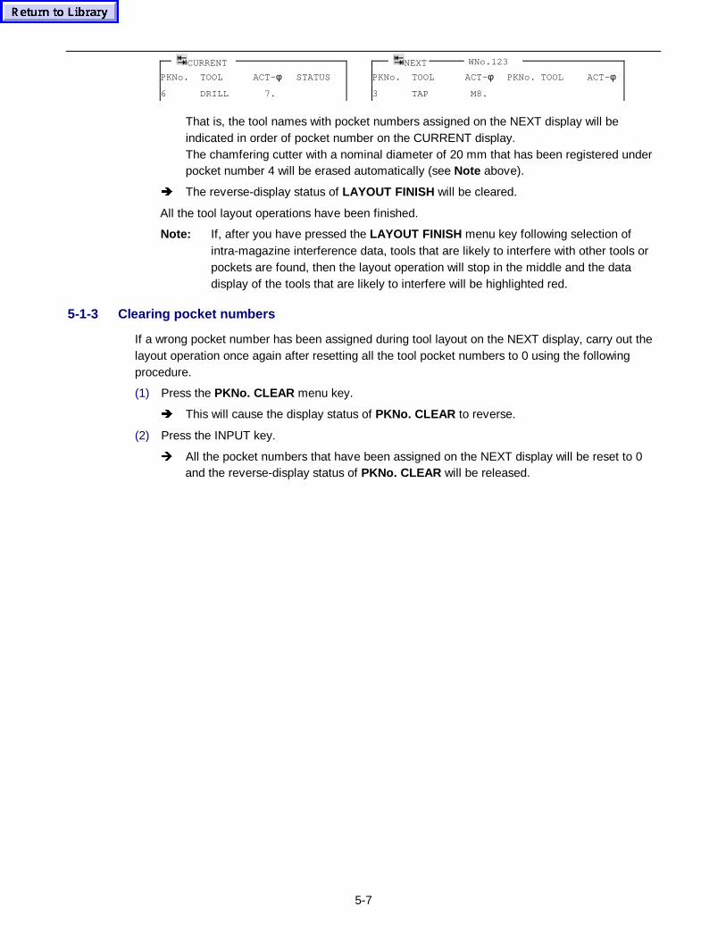
5-7
CURRENT NEXT WNo.123
PKNo. TOOL ACT-φ STATUS PKNo. TOOL ACT-φ PKNo. TOOL ACT-φ
6 DRILL 7. 3 TAP M8.
That is, the tool names with pocket numbers assigned on the NEXT display will beindicated in order of pocket number on the CURRENT display.The chamfering cutter with a nominal diameter of 20 mm that has been registered underpocket number 4 will be erased automatically (see Note above).
Î The reverse-display status of LAYOUT FINISH will be cleared.
All the tool layout operations have been finished.
Note: If, after you have pressed the LAYOUT FINISH menu key following selection ofintra-magazine interference data, tools that are likely to interfere with other tools orpockets are found, then the layout operation will stop in the middle and the datadisplay of the tools that are likely to interfere will be highlighted red.
5-1-3 Clearing pocket numbers
If a wrong pocket number has been assigned during tool layout on the NEXT display, carry out thelayout operation once again after resetting all the tool pocket numbers to 0 using the followingprocedure.
(1) Press the PKNo. CLEAR menu key.
Î This will cause the display status of PKNo. CLEAR to reverse.
(2) Press the INPUT key.
Î All the pocket numbers that have been assigned on the NEXT display will be reset to 0and the reverse-display status of PKNo. CLEAR will be released.
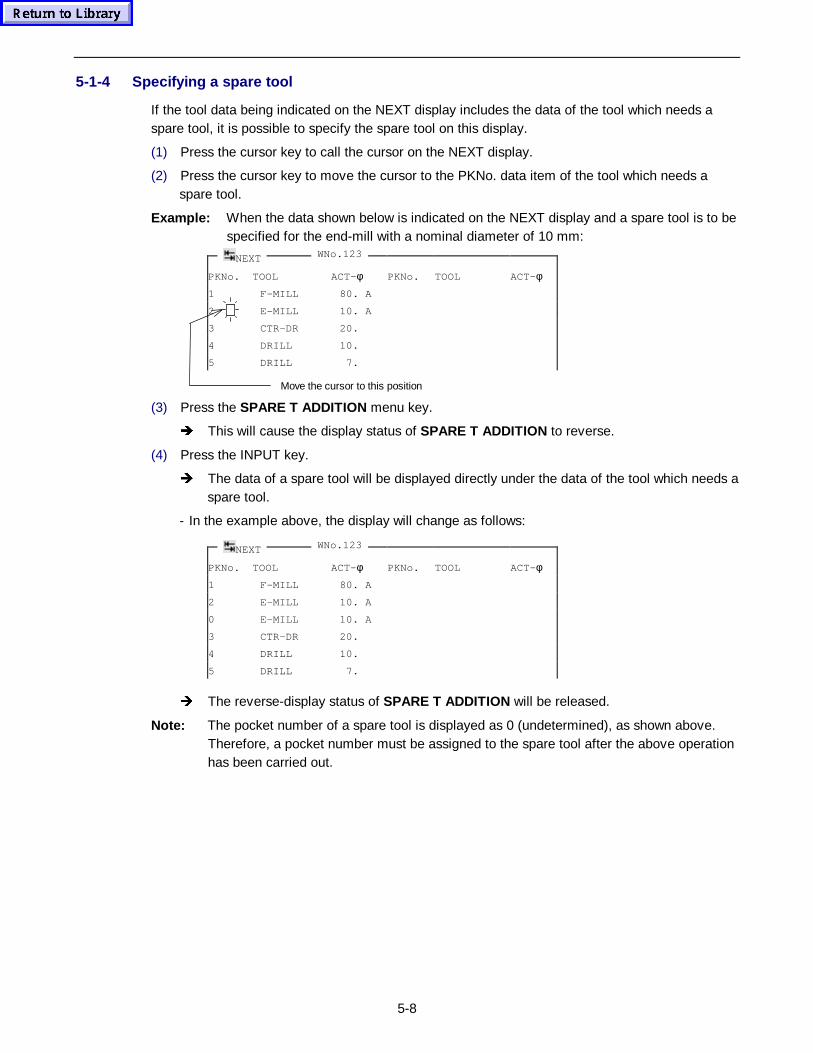
5-8
5-1-4 Specifying a spare tool
If the tool data being indicated on the NEXT display includes the data of the tool which needs aspare tool, it is possible to specify the spare tool on this display.
(1) Press the cursor key to call the cursor on the NEXT display.
(2) Press the cursor key to move the cursor to the PKNo. data item of the tool which needs aspare tool.
Example: When the data shown below is indicated on the NEXT display and a spare tool is to bespecified for the end-mill with a nominal diameter of 10 mm:
PKNo. TOOL ACT-φ PKNo. TOOL ACT-φ
1 F-MILL 80. A
2 E-MILL 10. A
3 CTR-DR 20.
4 DRILL 10.
5 DRILL 7.
(3) Press the SPARE T ADDITION menu key.
Î This will cause the display status of SPARE T ADDITION to reverse.
(4) Press the INPUT key.
Î The data of a spare tool will be displayed directly under the data of the tool which needs aspare tool.
- In the example above, the display will change as follows:
PKNo. TOOL ACT-φ PKNo. TOOL ACT-φ
1 F-MILL 80. A
2 E-MILL 10. A
0 E-MILL 10. A
3 CTR-DR 20.
4 DRILL 10.
5 DRILL 7.
Î The reverse-display status of SPARE T ADDITION will be released.
Note: The pocket number of a spare tool is displayed as 0 (undetermined), as shown above.Therefore, a pocket number must be assigned to the spare tool after the above operationhas been carried out.
Move the cursor to this position
NEXT WNo.123
NEXT WNo.123
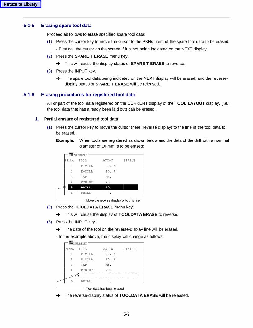
5-9
5-1-5 Erasing spare tool data
Proceed as follows to erase specified spare tool data:
(1) Press the cursor key to move the cursor to the PKNo. item of the spare tool data to be erased.
- First call the cursor on the screen if it is not being indicated on the NEXT display.
(2) Press the SPARE T ERASE menu key.
Î This will cause the display status of SPARE T ERASE to reverse.
(3) Press the INPUT key.
Î The spare tool data being indicated on the NEXT display will be erased, and the reverse-display status of SPARE T ERASE will be released.
5-1-6 Erasing procedures for registered tool data
All or part of the tool data registered on the CURRENT display of the TOOL LAYOUT display, (i.e.,the tool data that has already been laid out) can be erased.
1. Partial erasure of registered t ool data
(1) Press the cursor key to move the cursor (here: reverse display) to the line of the tool data tobe erased.
Example: When tools are registered as shown below and the data of the drill with a nominaldiameter of 10 mm is to be erased:
PKNo. TOOL ACT-φ STATUS
1 F-MILL 80. A
2 E-MILL 10. A
3 TAP M8.
4 CTR-DR 20.
5 DRILL 10.
6 DRILL 7.
Move the reverse display onto this line.
(2) Press the TOOLDATA ERASE menu key.
Î This will cause the display of TOOLDATA ERASE to reverse.
(3) Press the INPUT key.
Î The data of the tool on the reverse-display line will be erased.
- In the example above, the display will change as follows:
PKNo. TOOL ACT-φ STATUS
1 F-MILL 80. A
2 E-MILL 10. A
3 TAP M8.
4 CTR-DR 20.
5
6 DRILL 7.
Tool data has been erased.
Î The reverse-display status of TOOLDATA ERASE will be released.
CURRENT
CURRENT
5-10
2. Total erasure of registered t ool data
(1) Press the menu selector key to display LAYOUT CANCEL .
(2) Press the LAYOUT CANCEL menu key.
Î This will cause the display status of LAYOUT CANCEL to reverse.
(3) Specify −9999 with the numeric keys and then press the INPUT key.
Î The entire tool data that has been registered on the CURRENT display will then beerased and the reverse-display status of LAYOUT CANCEL will be released.
5-1-7 Other functions
1. TOOL SEARCH
This menu data should be used to search for a tool name that is registered on the CURRENTdisplay.The operating procedure is similar to that used for TOOL SEARCH of the TOOL DATA display.For details, see the Section 7-1 TOOL DATA Display .
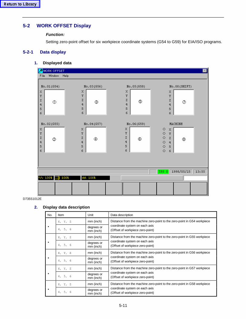
5-11
5-2 WORK OFFSET Display
Function:
Setting zero-point offset for six workpiece coordinate systems (G54 to G59) for EIA/ISO programs.
5-2-1 Data display
1. Displayed data
D735S1012E
2. Display data description
No. Item Unit Data description
X, Y, Z mm (inch)
•4, 5, 6
degrees ormm (inch)
Distance from the machine zero-point to the zero-point in G54 workpiececoordinate system on each axis(Offset of workpiece zero-point)
X, Y, Z mm (inch)
•4, 5, 6
degrees ormm (inch)
Distance from the machine zero-point to the zero-point in G55 workpiececoordinate system on each axis(Offset of workpiece zero-point)
X, Y, Z mm (inch)
•4, 5, 6
degrees ormm (inch)
Distance from the machine zero-point to the zero-point in G56 workpiececoordinate system on each axis(Offset of workpiece zero-point)
X, Y, Z mm (inch)
•4, 5, 6
degrees ormm (inch)
Distance from the machine zero-point to the zero-point in G57 workpiececoordinate system on each axis(Offset of workpiece zero-point)
X, Y, Z mm (inch)
•4, 5, 6
degrees ormm (inch)
Distance from the machine zero-point to the zero-point in G58 workpiececoordinate system on each axis(Offset of workpiece zero-point)
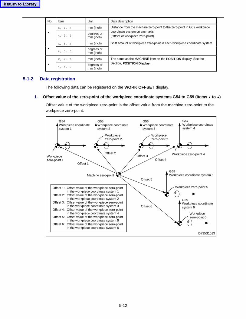
5-12
No. Item Unit Data description
X, Y, Z mm (inch)
•4, 5, 6
degrees ormm (inch)
Distance from the machine zero-point to the zero-point in G59 workpiececoordinate system on each axis(Offset of workpiece zero-point)
X, Y, Z mm (inch)
•4, 5, 6
degrees ormm (inch)
Shift amount of workpiece zero-point in each workpiece coordinate system.
X, Y, Z mm (inch)
•4, 5, 6
degrees ormm (inch)
The same as the MACHINE item on the POSITION display. See theSection, POSITION Display .
5-1-2 Data registration
The following data can be registered on the WORK OFFSET display.
1. Offset value of the zero-point of the workpi ece coor dinate systems G54 to G59 (items • to • )
Offset value of the workpiece zero-point is the offset value from the machine zero-point to theworkpiece zero-point.
D735S1013
Offset 2
G54Workpiece coordinatesystem 1
Workpiecezero-point 1
G55Workpiece coordinatesystem 2
G56Workpiece coordinatesystem 3
G57Workpiece coordinatesystem 4
Workpiece zero-point 4
G58Workpiece coordinate system 5
G59Workpiece coordinatesystem 6
Workpiece zero-point 5
Workpiecezero-point 6
Workpiecezero-point 3
Workpiecezero-point 2
Offset 3Offset 4
Offset 1
Offset 6
Offset 5
Offset 1: Offset value of the workpiece zero-pointin the workpiece coordinate system 1
Offset 2: Offset value of the workpiece zero-pointin the workpiece coordinate system 2
Offset 3: Offset value of the workpiece zero-pointin the workpiece coordinate system 3
Offset 4: Offset value of the workpiece zero-pointin the workpiece coordinate system 4
Offset 5: Offset value of the workpiece zero-pointin the workpiece coordinate system 5
Offset 6: Offset value of the workpiece zero-pointin the workpiece coordinate system 6
Machine zero-point
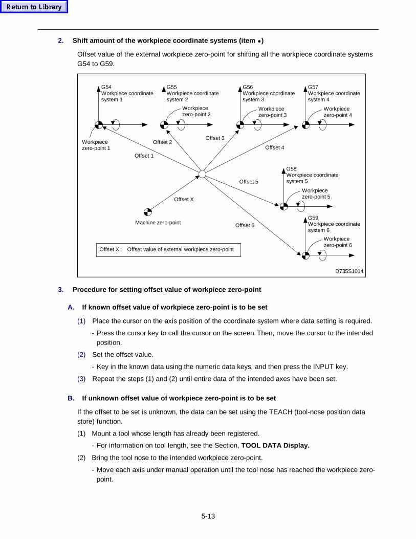
5-13
2. Shift amount of the workpi ece coor dinate systems (item • )
Offset value of the external workpiece zero-point for shifting all the workpiece coordinate systemsG54 to G59.
D735S1014
Offset 3
Offset 4
Offset 1
Offset 6
Offset 5
Machine zero-point
Offset X
Offset X : Offset value of external workpiece zero-point
Offset 2
G54Workpiece coordinatesystem 1
Workpiecezero-point 1
G55Workpiece coordinatesystem 2
G56Workpiece coordinatesystem 3
G57Workpiece coordinatesystem 4
G58Workpiece coordinatesystem 5
G59Workpiece coordinatesystem 6
Workpiecezero-point 2
Workpiecezero-point 3
Workpiecezero-point 4
Workpiecezero-point 5
Workpiecezero-point 6
3. Procedure for setting offset value of workpi ece zero- point
A. If known offset value of workpi ece zero- point is to be set
(1) Place the cursor on the axis position of the coordinate system where data setting is required.
- Press the cursor key to call the cursor on the screen. Then, move the cursor to the intendedposition.
(2) Set the offset value.
- Key in the known data using the numeric data keys, and then press the INPUT key.
(3) Repeat the steps (1) and (2) until entire data of the intended axes have been set.
B. If unknown offset value of workpi ece zero- point is to be set
If the offset to be set is unknown, the data can be set using the TEACH (tool-nose position datastore) function.
(1) Mount a tool whose length has already been registered.
- For information on tool length, see the Section, TOOL DATA Display.
(2) Bring the tool nose to the intended workpiece zero-point.
- Move each axis under manual operation until the tool nose has reached the workpiece zero-point.
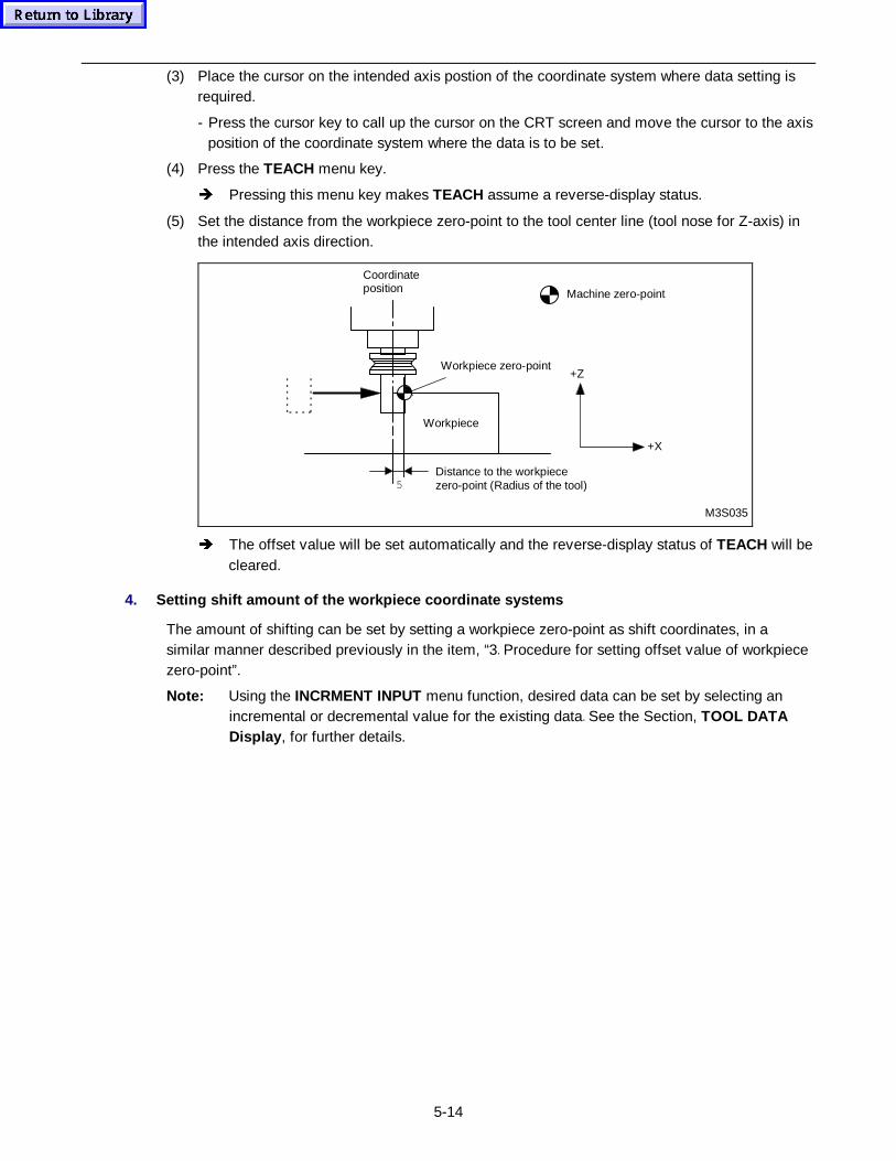
5-14
(3) Place the cursor on the intended axis postion of the coordinate system where data setting isrequired.
- Press the cursor key to call up the cursor on the CRT screen and move the cursor to the axisposition of the coordinate system where the data is to be set.
(4) Press the TEACH menu key.
Î Pressing this menu key makes TEACH assume a reverse-display status.
(5) Set the distance from the workpiece zero-point to the tool center line (tool nose for Z-axis) inthe intended axis direction.
5
+Z
+X
M3S035
Machine zero-point
Coordinateposition
Workpiece zero-point
Workpiece
Distance to the workpiecezero-point (Radius of the tool)
Î The offset value will be set automatically and the reverse-display status of TEACH will becleared.
4. Setting shift amount of the workpi ece coor dinate systems
The amount of shifting can be set by setting a workpiece zero-point as shift coordinates, in asimilar manner described previously in the item, “3. Procedure for setting offset value of workpiecezero-point”.
Note: Using the INCRMENT INPUT menu function, desired data can be set by selecting anincremental or decremental value for the existing data. See the Section, TOOL DATADisplay , for further details.
5-15
5-3 MACRO VARIABLE Display
Function:
This display allows macro variables to be set for the user macros.
Remarks:
- Two types of macro variables can be used:a) Common variables.................................... Can be used for both the main program and the
macro programs that are to be called up from themain program.
b) Local vairables.......................................... Can only be used in macro programs.
- The macro variable displays consist of the four sub-displays listed below.
a) COMMON VARIABLE display .................. Allows the operator to set the common variables tobe used to execute user macros in the automaticoperation mode.
b) COMMON VARIABLE (CHECK) display... Allows the operator to set the common variables tobe used to carry out tool path checks.
c) LOCAL VARIABLE display....................... Allows the operator to check the local variables tobe used to execute user macros in the automaticoperation mode.
d) LOCAL VARIABLE (CHECK) display ....... Allows the operator to check the local variables tobe used to carry out tool path checks.
Note: The LOCAL VARIABLE and LOCAL VARIABLE (CHECK) displays only list settings ofvariables; the data on these two displays cannot be modified.Refer to the EIA/ISO Programming Manual for further details of user macros.
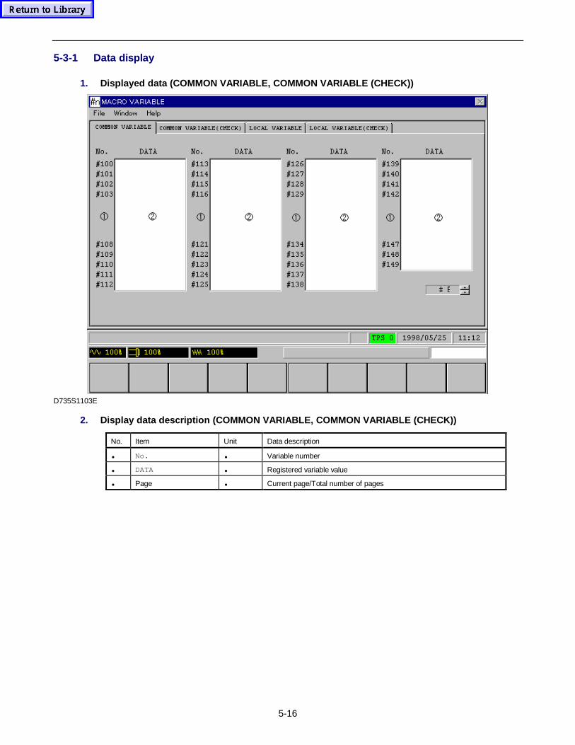
5-16
5-3-1 Data display
1. Displayed data (COMMON VARIABLE, COMMON VARIABLE (CHECK))
 %
D735S1103E
2. Display data descript ion (COMMON VARIABLE, COMMON VARIABLE (CHECK))
No. Item Unit Data description
• No. • Variable number
• DATA • Registered variable value
• Page • Current page/Total number of pages
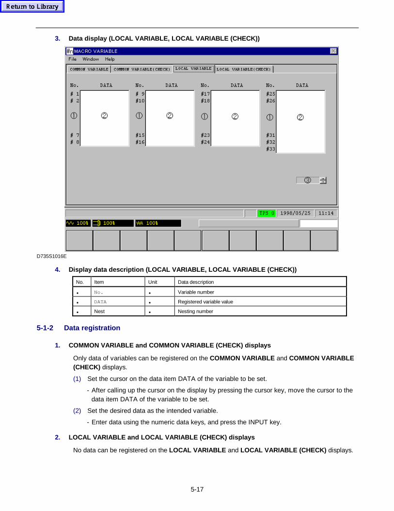
5-17
3. Data display (LOCAL VARIABLE, LOCAL VARIABLE (CHECK))
D735S1016E
4. Display data descript ion (LOCAL VARIABLE, LOCAL VARIABLE (CHECK))
No. Item Unit Data description
• No. • Variable number
• DATA • Registered variable value
• Nest • Nesting number
5-1-2 Data registration
1. COMMON VARIABLE and COMMON VARIABLE (CHECK) displays
Only data of variables can be registered on the COMMON VARIABLE and COMMON VARIABLE(CHECK) displays.
(1) Set the cursor on the data item DATA of the variable to be set.
- After calling up the cursor on the display by pressing the cursor key, move the cursor to thedata item DATA of the variable to be set.
(2) Set the desired data as the intended variable.
- Enter data using the numeric data keys, and press the INPUT key.
2. LOCAL VARIABLE and LOCAL VARIABLE (CHECK) displays
No data can be registered on the LOCAL VARIABLE and LOCAL VARIABLE (CHECK) displays.
5-18
5-1-3 Display operations
1. COMMON VARIABLE and COMMON VARIABLE (CHECK) displays
1. Pressing the INCRMENT INPUT menu key allows the entered data to be added to the currentdata.See the Section, TOOL DATA Display for further details.
2. Use the Exp menu item to set data in exponential form.
Example: To set the data 2 × 10⁻⁶, press keys in the following order:
2 Exp
−
6
This displays “2. E – 6” under DATA item.
3. The data on the COMMON VARIABLE and COMMON VARIABLE (CHECK) displays havebeen registered over multiple pages.
Pressing the page key displays the next page.
Pressing the page key displays the previous page.
2. LOCAL VARIABLE and LOCAL VARIABLE (CHECK) displays
The data on the LOCAL VARIABLE and LOCAL VARIABLE (CHECK) displays have beenregistered on nesting levels 1 to 5 per display. The number displayed on the data item• denotesthe nesting level of the current data.
- Pressing the page key displays data of the next nesting.
- Pressing the page key displays data of the previous nesting.
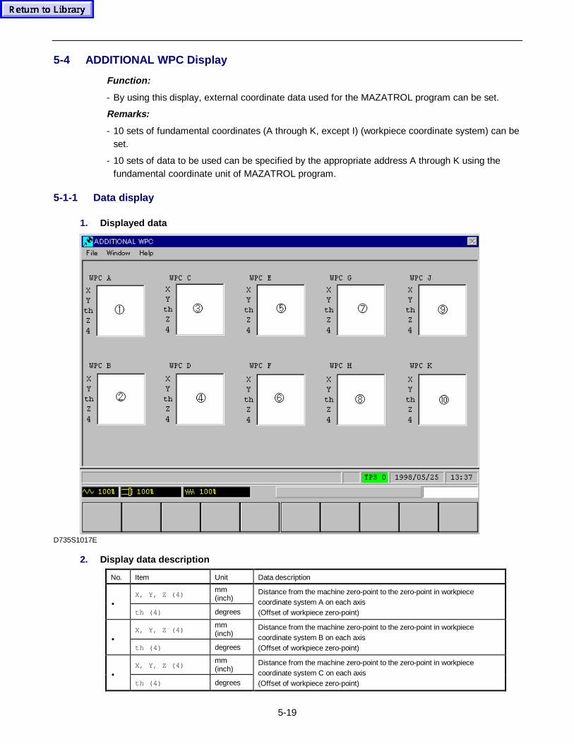
5-19
5-4 ADDITIONAL WPC Display
Function:
- By using this display, external coordinate data used for the MAZATROL program can be set.
Remarks:
- 10 sets of fundamental coordinates (A through K, except I) (workpiece coordinate system) can beset.
- 10 sets of data to be used can be specified by the appropriate address A through K using thefundamental coordinate unit of MAZATROL program.
5-1-1 Data display
1. Displayed data
D735S1017E
2. Display data description
No. Item Unit Data description
X, Y, Z (4)mm(inch)
•th (4) degrees
Distance from the machine zero-point to the zero-point in workpiececoordinate system A on each axis(Offset of workpiece zero-point)
X, Y, Z (4)mm(inch)
•th (4) degrees
Distance from the machine zero-point to the zero-point in workpiececoordinate system B on each axis(Offset of workpiece zero-point)
X, Y, Z (4)mm(inch)
•th (4) degrees
Distance from the machine zero-point to the zero-point in workpiececoordinate system C on each axis(Offset of workpiece zero-point)
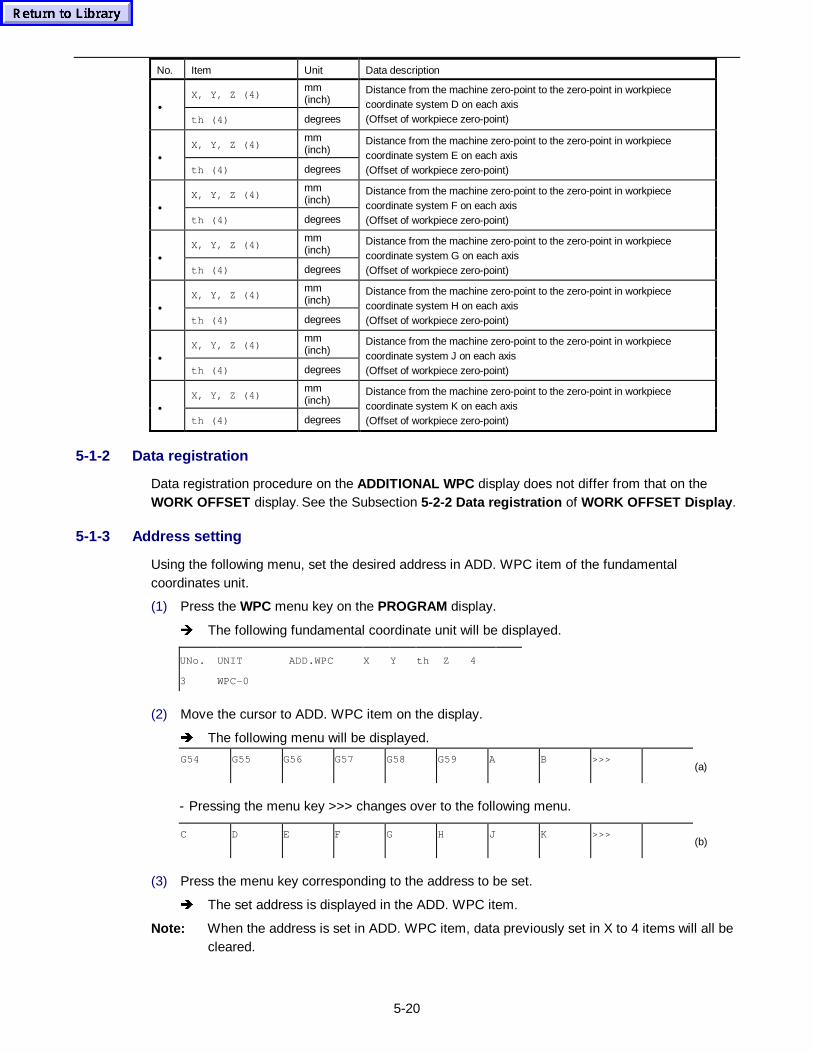
5-20
No. Item Unit Data description
X, Y, Z (4)mm(inch)
•th (4) degrees
Distance from the machine zero-point to the zero-point in workpiececoordinate system D on each axis(Offset of workpiece zero-point)
X, Y, Z (4)mm(inch)
•th (4) degrees
Distance from the machine zero-point to the zero-point in workpiececoordinate system E on each axis(Offset of workpiece zero-point)
X, Y, Z (4)mm(inch)
•th (4) degrees
Distance from the machine zero-point to the zero-point in workpiececoordinate system F on each axis(Offset of workpiece zero-point)
X, Y, Z (4)mm(inch)
•th (4) degrees
Distance from the machine zero-point to the zero-point in workpiececoordinate system G on each axis(Offset of workpiece zero-point)
X, Y, Z (4)mm(inch)
•th (4) degrees
Distance from the machine zero-point to the zero-point in workpiececoordinate system H on each axis(Offset of workpiece zero-point)
X, Y, Z (4)mm(inch)
•th (4) degrees
Distance from the machine zero-point to the zero-point in workpiececoordinate system J on each axis(Offset of workpiece zero-point)
X, Y, Z (4)mm(inch)
•th (4) degrees
Distance from the machine zero-point to the zero-point in workpiececoordinate system K on each axis(Offset of workpiece zero-point)
5-1-2 Data registration
Data registration procedure on the ADDITIONAL WPC display does not differ from that on theWORK OFFSET display. See the Subsection 5-2-2 Data registration of WORK OFFSET Display .
5-1-3 Address setting
Using the following menu, set the desired address in ADD. WPC item of the fundamentalcoordinates unit.
(1) Press the WPC menu key on the PROGRAM display.
Î The following fundamental coordinate unit will be displayed.
UNo. UNIT ADD.WPC X Y th Z 4
3 WPC-0
(2) Move the cursor to ADD. WPC item on the display.
Î The following menu will be displayed.
G54 G55 G56 G57 G58 G59 A B >>>(a)
- Pressing the menu key >>> changes over to the following menu.
C D E F G H J K >>>(b)
(3) Press the menu key corresponding to the address to be set.
Î The set address is displayed in the ADD. WPC item.
Note: When the address is set in ADD. WPC item, data previously set in X to 4 items will all becleared.
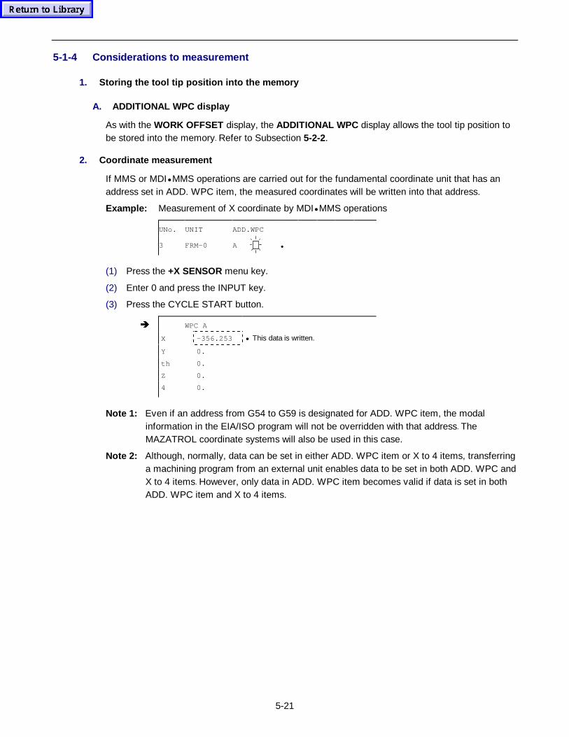
5-21
5-1-4 Considerations to measurement
1. Storing the tool tip position into the memory
A. ADDITIONAL WPC display
As with the WORK OFFSET display, the ADDITIONAL WPC display allows the tool tip position tobe stored into the memory. Refer to Subsection 5-2-2.
2. Coordinate measurement
If MMS or MDI• MMS operations are carried out for the fundamental coordinate unit that has anaddress set in ADD. WPC item, the measured coordinates will be written into that address.
Example: Measurement of X coordinate by MDI• MMS operations
UNo. UNIT ADD.WPC
3 FRM-0 A •
(1) Press the +X SENSOR menu key.
(2) Enter 0 and press the INPUT key.
(3) Press the CYCLE START button.
Î WPC A
X -356.253 • This data is written.
Y 0.
th 0.
Z 0.
4 0.
Note 1: Even if an address from G54 to G59 is designated for ADD. WPC item, the modalinformation in the EIA/ISO program will not be overridden with that address. TheMAZATROL coordinate systems will also be used in this case.
Note 2: Although, normally, data can be set in either ADD. WPC item or X to 4 items, transferringa machining program from an external unit enables data to be set in both ADD. WPC andX to 4 items. However, only data in ADD. WPC item becomes valid if data is set in bothADD. WPC item and X to 4 items.
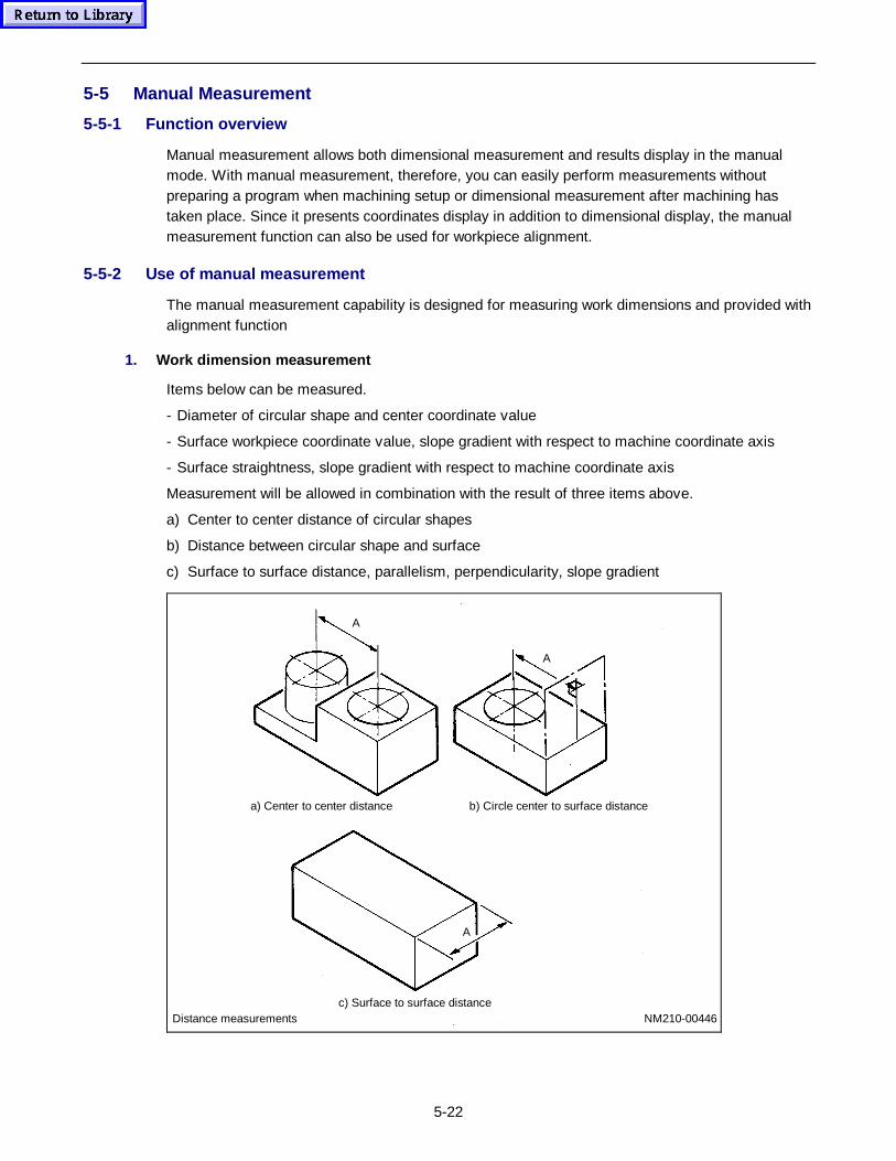
5-22
5-5 Manual Measurement
5-5-1 Function overview
Manual measurement allows both dimensional measurement and results display in the manualmode. With manual measurement, therefore, you can easily perform measurements withoutpreparing a program when machining setup or dimensional measurement after machining hastaken place. Since it presents coordinates display in addition to dimensional display, the manualmeasurement function can also be used for workpiece alignment.
5-5-2 Use of manual measurement
The manual measurement capability is designed for measuring work dimensions and provided withalignment function
1. Work dimension measurement
Items below can be measured.
- Diameter of circular shape and center coordinate value
- Surface workpiece coordinate value, slope gradient with respect to machine coordinate axis
- Surface straightness, slope gradient with respect to machine coordinate axis
Measurement will be allowed in combination with the result of three items above.
a) Center to center distance of circular shapes
b) Distance between circular shape and surface
c) Surface to surface distance, parallelism, perpendicularity, slope gradient
Distance measurementsc) Surface to surface distance
a) Center to center distance b) Circle center to surface distance
A
A
A
NM210-00446
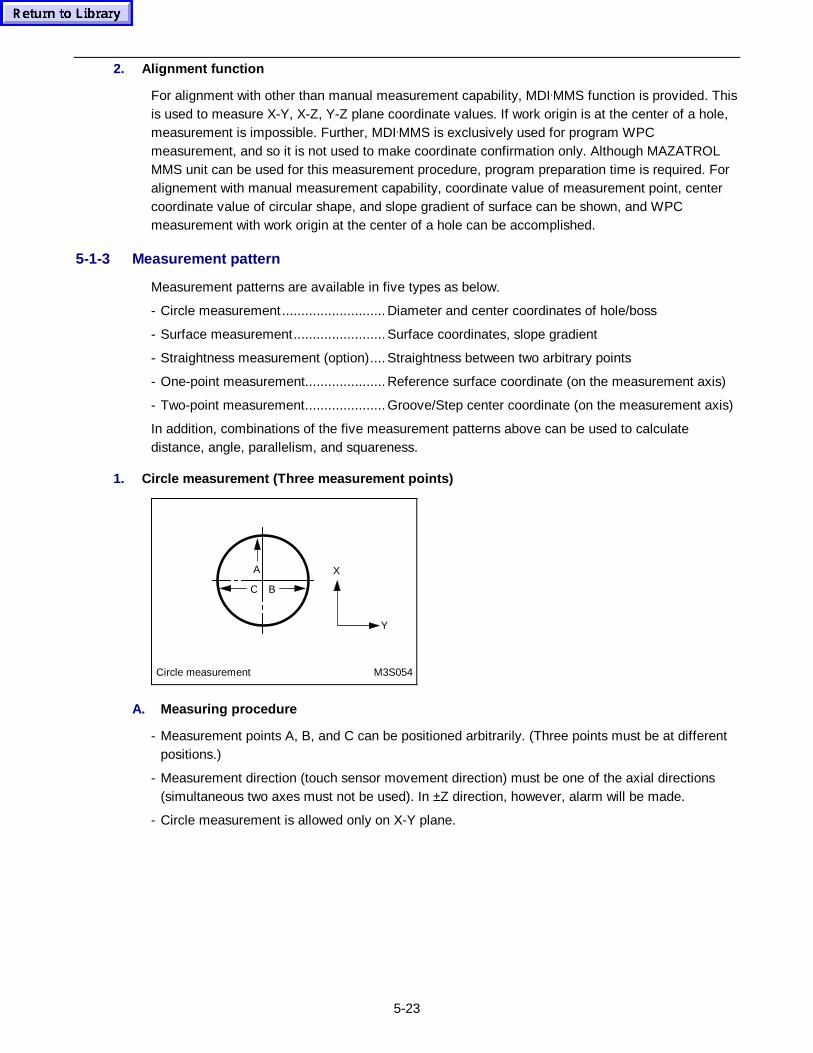
5-23
2. Alignment function
For alignment with other than manual measurement capability, MDI•MMS function is provided. Thisis used to measure X-Y, X-Z, Y-Z plane coordinate values. If work origin is at the center of a hole,measurement is impossible. Further, MDI•MMS is exclusively used for program WPCmeasurement, and so it is not used to make coordinate confirmation only. Although MAZATROLMMS unit can be used for this measurement procedure, program preparation time is required. Foralignement with manual measurement capability, coordinate value of measurement point, centercoordinate value of circular shape, and slope gradient of surface can be shown, and WPCmeasurement with work origin at the center of a hole can be accomplished.
5-1-3 Measurement pattern
Measurement patterns are available in five types as below.
- Circle measurement........................... Diameter and center coordinates of hole/boss
- Surface measurement........................ Surface coordinates, slope gradient
- Straightness measurement (option).... Straightness between two arbitrary points
- One-point measurement..................... Reference surface coordinate (on the measurement axis)
- Two-point measurement..................... Groove/Step center coordinate (on the measurement axis)
In addition, combinations of the five measurement patterns above can be used to calculatedistance, angle, parallelism, and squareness.
1. Circle measurement (Three measurement points)
A
Circle measurement M3S054
BC
X
Y
A. Measur ing procedure
- Measurement points A, B, and C can be positioned arbitrarily. (Three points must be at differentpositions.)
- Measurement direction (touch sensor movement direction) must be one of the axial directions(simultaneous two axes must not be used). In ±Z direction, however, alarm will be made.
- Circle measurement is allowed only on X-Y plane.
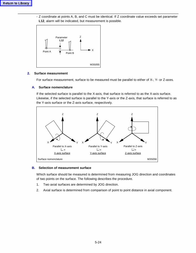
5-24
- Z coordinate at points A, B, and C must be identical. If Z coordinate value exceeds set parameterL12, alarm will be indicated, but measurement is possible.
Z
XPoint B
Point A
ParameterL12
M3S055
2. Surface measurement
For surface measurement, surface to be measured must be parallel to either of X-, Y- or Z-axes.
A. Surface nomenclature
If the selected surface is parallel to the X-axis, that surface is referred to as the X-axis surface.Likewise, if the selected surface is parallel to the Y-axis or the Z-axis, that surface is referred to asthe Y-axis surface or the Z-axis surface, respectively.
Z
X Y
Z
X Y
Surface nomenclature M3S056
Parallel to Z-axis�©
Z-axis surface
Parallel to Y-axis�©
Y-axis surface
Parallel to X-axis�©
X-axis surface
Z
X Y
B. Selection of measurement surface
Which surface should be measured is determined from measuring JOG direction and coordinatesof two points on the surface. The following describes the procedure.
1. Two axial surfaces are determined by JOG direction.
2. Axial surface is determined from comparison of point to point distance in axial component.
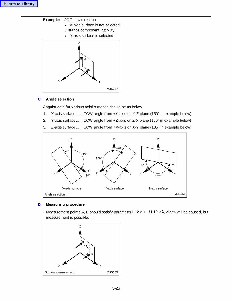
5-25
Example: JOG in X direction• X-axis surface is not selected.Distance component: λz > λy• Y-axis surface is selected
Z
X Y
Oz
Oy
M3S057
C. Angle selection
Angular data for various axial surfaces should be as below.
1. X-axis surface ...... CCW angle from +Y-axis on Y-Z plane (150° in example below)
2. Y-axis surface ...... CCW angle from +Z-axis on Z-X plane (160° in example below)
3. Z-axis surface ...... CCW angle from +X-axis on X-Y plane (135° in example below)
Z
X Y
Angle selection
X-axis surface Y-axis surface Z-axis surface
Z
X Y
Z
XY
–30°
M3S058
150°160°
–20°
–45°
135°
D. Measur ing procedure
- Measurement points A, B should satisfy parameter L12 ≥ λ. If L12 < λ, alarm will be caused, butmeasurement is possible.
Z
X Y
A
O
B
Surface measurement M3S059
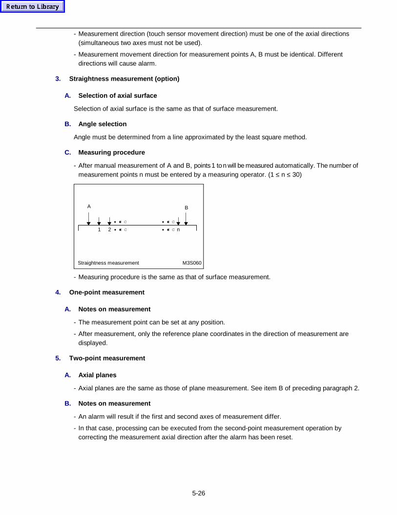
5-26
- Measurement direction (touch sensor movement direction) must be one of the axial directions(simultaneous two axes must not be used).
- Measurement movement direction for measurement points A, B must be identical. Differentdirections will cause alarm.
3. Straightn ess measurement (opt ion)
A. Selection of axial surface
Selection of axial surface is the same as that of surface measurement.
B. Angle selection
Angle must be determined from a line approximated by the least square method.
C. Measur ing procedure
- After manual measurement of A and B, points 1 to n will be measured automatically. The number ofmeasurement points n must be entered by a measuring operator. (1 ≤ n ≤ 30)
• c• c • c• c
1 2 • c• c • c• c n
Straightness measurement M3S060
A B
- Measuring procedure is the same as that of surface measurement.
4. One-point measurement
A. Notes on measurement
- The measurement point can be set at any position.
- After measurement, only the reference plane coordinates in the direction of measurement aredisplayed.
5. Two-point measurement
A. Axial planes
- Axial planes are the same as those of plane measurement. See item B of preceding paragraph 2.
B. Notes on measurement
- An alarm will result if the first and second axes of measurement differ.
- In that case, processing can be executed from the second-point measurement operation bycorrecting the measurement axial direction after the alarm has been reset.
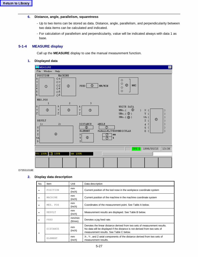
5-27
6. Distance, angle, p arallelism, squaretness
- Up to two items can be stored as data. Distance, angle, parallelism, and perpendicularity betweentwo data items can be calculated and indicated.
- For calculation of parallelism and perpendicularity, value will be indicated always with data 1 asbase.
5-1-4 MEASURE display
Call up the MEASURE display to use the manual measurement function.
1. Displayed data
D735S1018E
2. Display data description
No. Item Unit Data description
• POSITIONmm(inch)
Current position of the tool nose in the workpiece coordinate system
• MACHINEmm(inch)
Current position of the machine in the machine coordinate system
• MES. POSmm(inch)
Coordinates of the measurement point. See Table A below.
• RESULTmm(inch)
Measurement results are displayed. See Table B below.
• FEEDmm/min(ft/min)
Denotes a jog feed rate.
DISTANCEmm(inch)
Denotes the linear distance derived from two sets of measurement results.No data will be displayed if the distance is not derived from two sets ofmeasurement results. See Table C below.•
ELEMENTmm(inch)
X-, Y-, and Z-axial components of the distance derived from two sets ofmeasurement results.
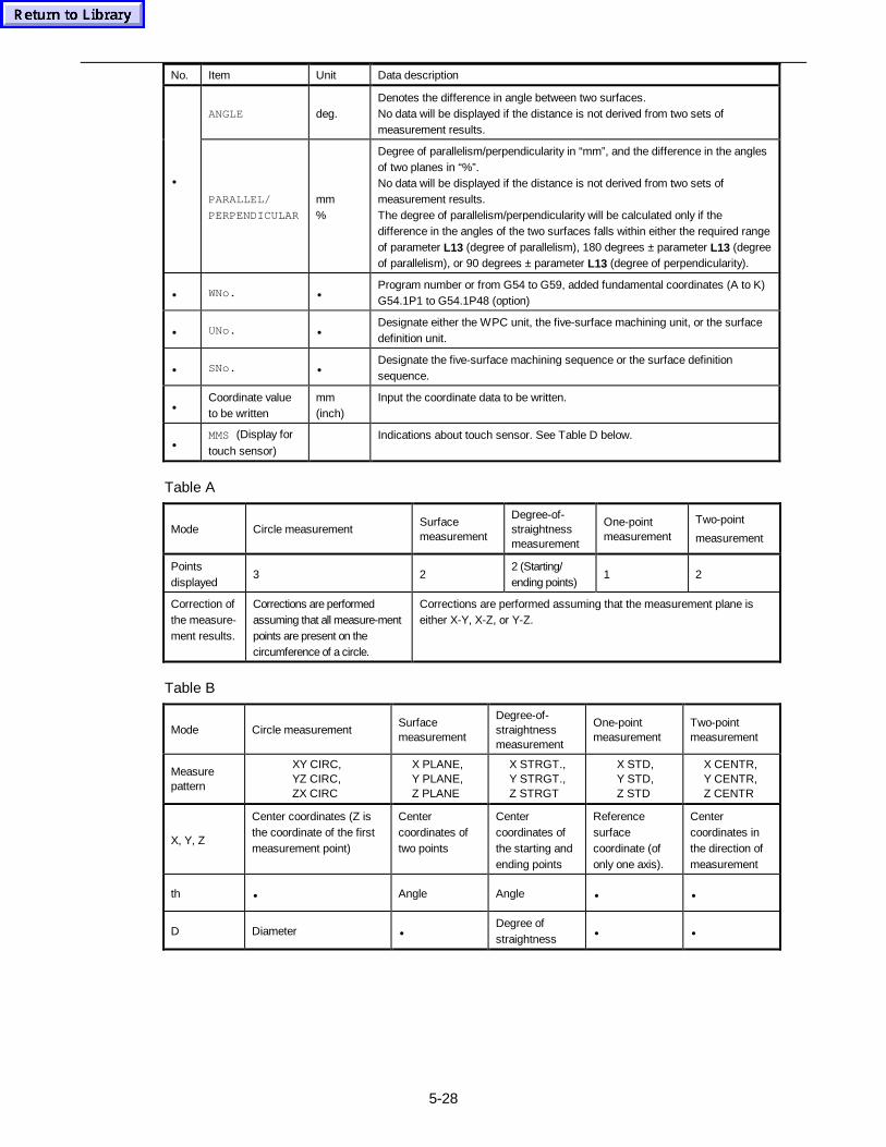
5-28
No. Item Unit Data description
ANGLE deg.Denotes the difference in angle between two surfaces.No data will be displayed if the distance is not derived from two sets ofmeasurement results.
•
PARALLEL/
PERPENDICULAR
mm%
Degree of parallelism/perpendicularity in “mm”, and the difference in the anglesof two planes in “%”.No data will be displayed if the distance is not derived from two sets ofmeasurement results.The degree of parallelism/perpendicularity will be calculated only if thedifference in the angles of the two surfaces falls within either the required rangeof parameter L13 (degree of parallelism), 180 degrees ± parameter L13 (degreeof parallelism), or 90 degrees ± parameter L13 (degree of perpendicularity).
• WNo. •Program number or from G54 to G59, added fundamental coordinates (A to K)G54.1P1 to G54.1P48 (option)
• UNo. •Designate either the WPC unit, the five-surface machining unit, or the surfacedefinition unit.
• SNo. •Designate the five-surface machining sequence or the surface definitionsequence.
•Coordinate valueto be written
mm(inch)
Input the coordinate data to be written.
•MMS (Display for
touch sensor)Indications about touch sensor. See Table D below.
Table A
Mode Circle measurementSurfacemeasurement
Degree-of-straightnessmeasurement
One-pointmeasurement
Two-point
measurement
Pointsdisplayed
3 22 (Starting/ending points)
1 2
Correction ofthe measure-ment results.
Corrections are performedassuming that all measure-mentpoints are present on thecircumference of a circle.
Corrections are performed assuming that the measurement plane iseither X-Y, X-Z, or Y-Z.
Table B
Mode Circle measurementSurfacemeasurement
Degree-of-straightnessmeasurement
One-pointmeasurement
Two-pointmeasurement
Measurepattern
XY CIRC,YZ CIRC,ZX CIRC
X PLANE,Y PLANE,Z PLANE
X STRGT.,Y STRGT.,Z STRGT
X STD,Y STD,Z STD
X CENTR,Y CENTR,Z CENTR
X, Y, Z
Center coordinates (Z isthe coordinate of the firstmeasurement point)
Centercoordinates oftwo points
Centercoordinates ofthe starting andending points
Referencesurfacecoordinate (ofonly one axis).
Centercoordinates inthe direction ofmeasurement
th • Angle Angle • •
D Diameter •Degree ofstraightness
• •
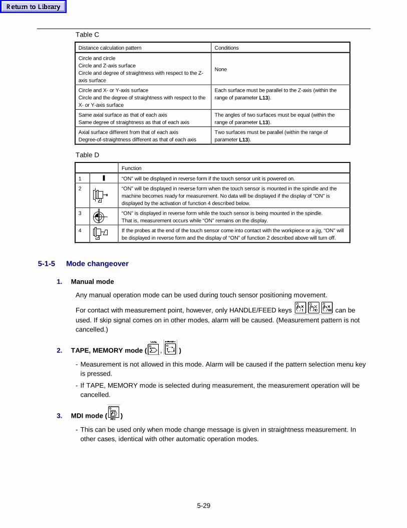
5-29
Table C
Distance calculation pattern Conditions
Circle and circleCircle and Z-axis surfaceCircle and degree of straightness with respect to the Z-axis surface
None
Circle and X- or Y-axis surfaceCircle and the degree of straightness with respect to theX- or Y-axis surface
Each surface must be parallel to the Z-axis (within therange of parameter L13).
Same axial surface as that of each axisSame degree of straightness as that of each axis
The angles of two surfaces must be equal (within therange of parameter L13).
Axial surface different from that of each axisDegree-of-straightness different as that of each axis
Two surfaces must be parallel (within the range ofparameter L13).
Table D
Function
1 “ON” will be displayed in reverse form if the touch sensor unit is powered on.
2 “ON” will be displayed in reverse form when the touch sensor is mounted in the spindle and themachine becomes ready for measurement. No data will be displayed if the display of “ON” isdisplayed by the activation of function 4 described below.
3 “ON” is displayed in reverse form while the touch sensor is being mounted in the spindle.That is, measurement occurs while “ON” remains on the display.
4 If the probes at the end of the touch sensor come into contact with the workpiece or a jig, “ON” willbe displayed in reverse form and the display of “ON” of function 2 described above will turn off.
5-1-5 Mode changeover
1. Manual mode
Any manual operation mode can be used during touch sensor positioning movement.
For contact with measurement point, however, only HANDLE/FEED keys can be
used. If skip signal comes on in other modes, alarm will be caused. (Measurement pattern is notcancelled.)
2. TAPE, MEMORY mode ( , )
- Measurement is not allowed in this mode. Alarm will be caused if the pattern selection menu keyis pressed.
- If TAPE, MEMORY mode is selected during measurement, the measurement operation will becancelled.
3. MDI mode ( )
- This can be used only when mode change message is given in straightness measurement. Inother cases, identical with other automatic operation modes.
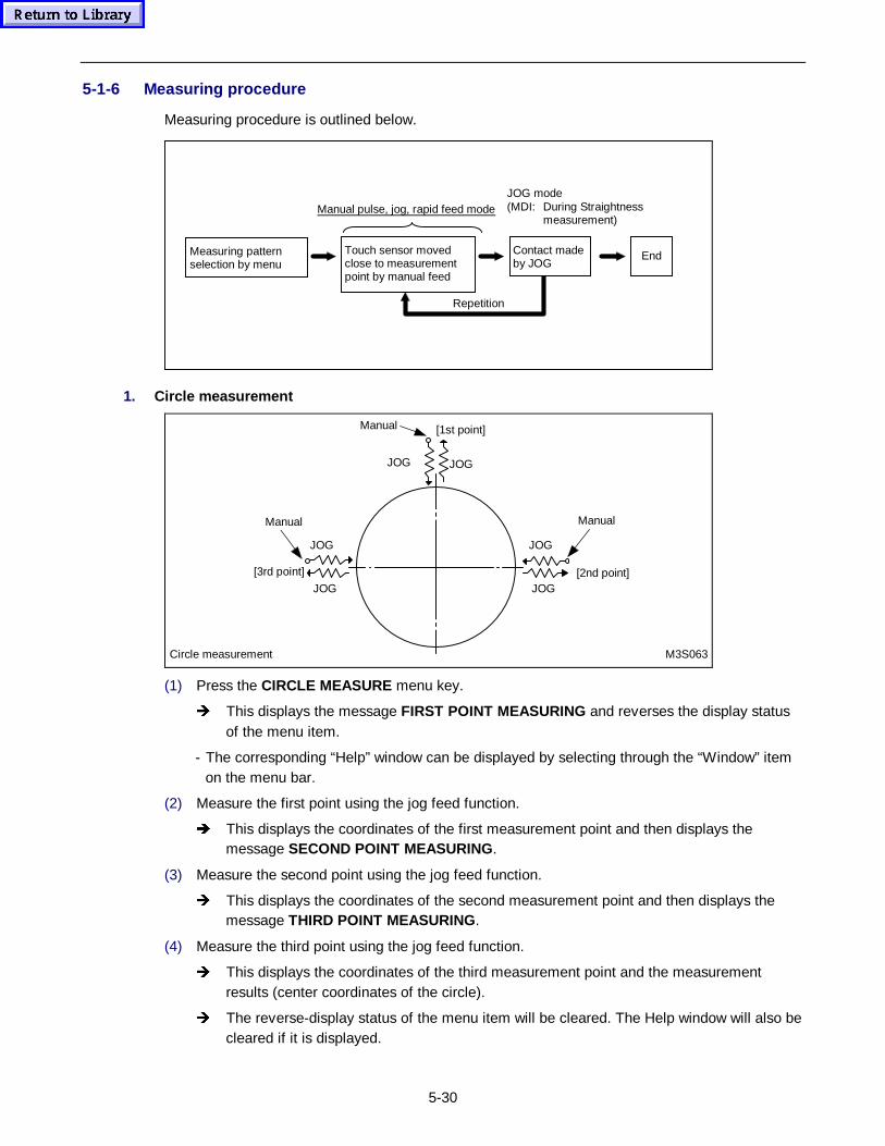
5-30
5-1-6 Measuring procedure
Measuring procedure is outlined below.
Repetition
Measuring patternselection by menu
EndContact madeby JOG
Touch sensor movedclose to measurementpoint by manual feed
Manual pulse, jog, rapid feed modeJOG mode(MDI: During Straightness
measurement)
1. Circle measurement
JOG
[3rd point] [2nd point]
[1st point]
JOG
Circle measurement M3S063
JOG
JOG
Manual Manual
JOG
JOG
Manual
(1) Press the CIRCLE MEASURE menu key.
Î This displays the message FIRST POINT MEASURING and reverses the display statusof the menu item.
- The corresponding “Help” window can be displayed by selecting through the “Window” itemon the menu bar.
(2) Measure the first point using the jog feed function.
Î This displays the coordinates of the first measurement point and then displays themessage SECOND POINT MEASURING.
(3) Measure the second point using the jog feed function.
Î This displays the coordinates of the second measurement point and then displays themessage THIRD POINT MEASURING.
(4) Measure the third point using the jog feed function.
Î This displays the coordinates of the third measurement point and the measurementresults (center coordinates of the circle).
Î The reverse-display status of the menu item will be cleared. The Help window will also becleared if it is displayed.
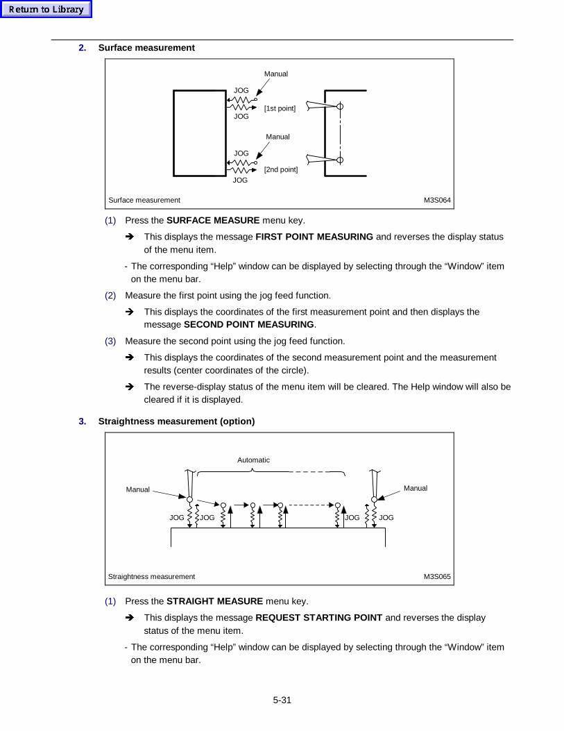
5-31
2. Surface measurement
JOG
[2nd point]
[1st point]
Manual
JOG
Surface measurement M3S064
JOG
JOG
Manual
(1) Press the SURFACE MEASURE menu key.
Î This displays the message FIRST POINT MEASURING and reverses the display statusof the menu item.
- The corresponding “Help” window can be displayed by selecting through the “Window” itemon the menu bar.
(2) Measure the first point using the jog feed function.
Î This displays the coordinates of the first measurement point and then displays themessage SECOND POINT MEASURING.
(3) Measure the second point using the jog feed function.
Î This displays the coordinates of the second measurement point and the measurementresults (center coordinates of the circle).
Î The reverse-display status of the menu item will be cleared. The Help window will also becleared if it is displayed.
3. Straightn ess measurement (opt ion)
JOG
Manual
Automatic
Manual
JOG JOG JOG
Straightness measurement M3S065
(1) Press the STRAIGHT MEASURE menu key.
Î This displays the message REQUEST STARTING POINT and reverses the displaystatus of the menu item.
- The corresponding “Help” window can be displayed by selecting through the “Window” itemon the menu bar.
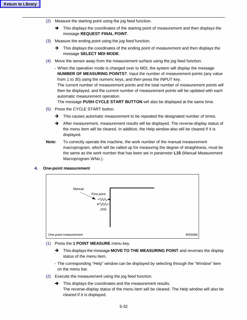
5-32
(2) Measure the starting point using the jog feed function.
Î This displays the coordinates of the starting point of measurement and then displays themessage REQUEST FINAL POINT .
(3) Measure the ending point using the jog feed function.
Î This displays the coordinates of the ending point of measurement and then displays themessage SELECT MDI MODE.
(4) Move the sensor away from the measurement surface using the jog feed function.
- When the operation mode is changed over to MDI, the system will display the messageNUMBER OF MEASURING POINTS? . Input the number of measurement points (any valuefrom 1 to 30) using the numeric keys, and then press the INPUT key.The current number of measurement points and the total number of measurement points willthen be displayed, and the current number of measurement points will be updated with eachautomatic measurement operation.The message PUSH CYCLE START BUTTON will also be displayed at the same time.
(5) Press the CYCLE START button.
Î This causes automatic measurement to be repeated the designated number of times.
Î After measurement, measurement results will be displayed. The reverse-display status ofthe menu item will be cleared. In addition, the Help window also will be cleared if it isdisplayed.
Note: To correctly operate the machine, the work number of the manual measurementmacroprogram, which will be called up for measuring the degree of straightness, must bethe same as the work number that has been set in parameter L15 (Manual MeasurementMacroprogram WNo.).
4. One-point measurement
JOG
First point
Manual
One-point measurement M3S066
(1) Press the 1 POINT MEASURE menu key.
Î This displays the message MOVE TO THE MEASURING POINT and reverses the displaystatus of the menu item.
- The corresponding “Help” window can be displayed by selecting through the “Window” itemon the menu bar.
(2) Execute the measurement using the jog feed function.
Î This displays the coordinates and the measurement results.The reverse-display status of the menu item will be cleared. The Help window will also becleared if it is displayed.
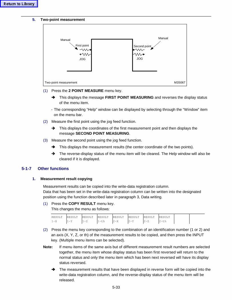
5-33
5. Two-point measurement
Two-point measurement M3S067
Manual Manual
JOG JOG
First point Second point
(1) Press the 2 POINT MEASURE menu key.
Î This displays the message FIRST POINT MEASURING and reverses the display statusof the menu item.
- The corresponding “Help” window can be displayed by selecting through the “Window” itemon the menu bar.
(2) Measure the first point using the jog feed function.
Î This displays the coordinates of the first measurement point and then displays themessage SECOND POINT MEASURING.
(3) Measure the second point using the jog feed function.
Î This displays the measurement results (the center coordinate of the two points).
Î The reverse-display status of the menu item will be cleared. The Help window will also becleared if it is displayed.
5-1-7 Other functions
1. Measurement result copying
Measurement results can be copied into the write-data registration column.Data that has been set in the write-data registration column can be written into the designatedposition using the function described later in paragraph 3, Data writing.
(1) Press the COPY RESULT menu key.This changes the menu as follows:
RESULT
1-X
RESULT
1-Y
RESULT
1-Z
RESULT
1-th
RESULT
2-X
RESULT
2-Y
RESULT
2-Z
RESULT
2-th
(2) Press the menu key corresponding to the combination of an identification number (1 or 2) andan axis (X, Y, Z, or th) of the measurement results to be copied, and then press the INPUTkey. (Multiple menu items can be selected).
Note: If menu items of the same axis but of different measurement result numbers are selectedtogether, the menu item whose display status has been first reversed will return to thenormal status and only the menu item which has been next reversed will have its displaystatus reversed.
Î The measurement results that have been displayed in reverse form will be copied into thewrite-data registration column, and the reverse-display status of the menu item will bereleased.
5-34
2. Measurement result clearing
Masurement results can be cleared.
(1) Press the CLEAR RESULT menu key.
Î This displays the message CLEAR MEASURING RESULT No.? .
(2) Input the identification number (1, 2, or 0) of the measurement results to be cleared, and thenpress the INPUT key.
Î The distance and angle items will then be cleared together with the measurement results.Thus, it will become possible for either of the two points to be measured once again.
- If number 0 is input, both 1 and 2 will be cleared.
3. Data writing
Data that has been set in the write-data registration column (WRITE DATA) can be written into thedesignated position.
(1) Display the cursor at the write-data registration column by pressing the cursor key.
(2) Set writing destination data.
- Use one of the following three methods to designate the writing destination:
(a) Writing into the fundamental coordinate unit:
WNo.• 123456M •
UNo. • 1 •
SNo. • •
Input the work number of the writing destination program using the numerickeys, and press the INPUT key.
Input the unit number within the program where the fundamental coordinateunit is contained, and press the INPUT key.
Set no data.
(b) Writing into work offsets (WORK OFFSET):
WNo.• G54 •
UNo. • •
SNo. • •
Set a code from G54 to G59 using the menu.
The cursor cannot be moved to ( ) if any code from G54 to G59 is set.
Writing into work offsets (Option)
WNo.• G54.1P6 •
UNo. • •
SNo. • •
Select "G54.1" from the menu. The message G54.1 P-CODE? will then be
displayed. Input the P number of the writing destination using the numeric
keys, and press the INPUT key.
The cursor cannot be moved to ( ) if any code from G54.1P1 to G54.1P48 is
set.
(c) Writing into additional work offsets (ADDITIONAL WPC):
WNo.• A •
UNo. • •
SNo. • •
Set a work number from A to K using the appropriate menu.
The cursor cannot be moved to ( ) if any code from A to K is set.
(3) Press the WRITE menu key.
Î This displays the message WRITE <INPUT>? and reverses the display status of themenu item.
(4) Press the INPUT key.
Î The coordinate data will then be written into the designated destination. When writing iscompleted, the reverse-display status of the menu item will be cleared.
- Data that has been set in “th” will be ignored if the coordinate data is written into workoffsets.
5-35
4. Incremental data input
The data to be written can be input in incremental form.
(1) Press the INCRMENT INPUT menu key.
Î This displays the message LENGTH TO ADD? and reverses the display status of themenu item.
(2) Input the data to be added, and press the INPUT key. The input data will then be added to thedata indicated by the cursor.
5. Entire data clearing
The entire data under the write-data setting column can be cleared.
Î Press the ALL CLEAR menu key.This displays the message ALL CLEAR? and reverses the display status of the menuitem.
(1) Press the INPUT key.
Î This clears the entire written data and turns off the reverse-display status of the menuitem.
6. Window functions
The following window functions are provided in the MEASURE display:
A. Help window
This window can be displayed by selecting through “Window” on the menu bar while either theCIRCLE MEASURE, SURFACE MEASURE, STRAGHT MEASURE, 1 POINT MEASURE, or 2POINT MEASURE menu item remains in the reverse-display status.
B. Work number listing window
This window can be displayed by using the PROGRAM FILE menu item while this menu itemremains on the display.
C. MAZATROL program window
While the work number of a program is designated at WNo. of WRITE DATA and the cursorremains set at WNo., UNo. or SNo., the MAZATROL program window corresponding to the WNo.and UNo. data can be displayed by selecting “Program” through “Window” on the menu bar. Thewindow, however, will not display any data if a unit number that has been selected at UNo. is notincluded in the program that has been selected at WNo.
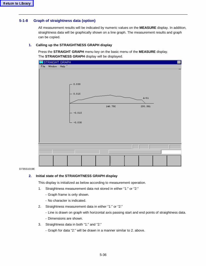
5-36
5-1-8 Graph of straightness data (option)
All measurement results will be indicated by numeric values on the MEASURE display. In addition,straightness data will be graphically shown on a line graph. The measurement results and graphcan be copied.
1. Calling up the STRAIGHTNESS GRAPH display
Press the STRAIGHT GRAPH menu key on the basic menu of the MEASURE display.The STRAIGHTNESS GRAPH display will be displayed.
D735S1019E
2. Initial state of the STRAIGHTNESS GRAPH display
This display is initialized as below according to measurement operation.
1. Straightness measurement data not stored in either “1:” or “2:”
- Graph frame is only shown.
- No character is indicated.
2. Straightness measurement data in either “1:” or “2:”
- Line is drawn on graph with horizontal axis passing start and end points of straightness data.
- Dimensions are shown.
3. Straightness data in both “1:” and “2:”
- Graph for data “2:” will be drawn in a manner similar to 2. above.

5-37
3. Menu function
A. MEASURE
Direct return from the graph to the MEASURE display.
B. PARALLEL PERPNDLR
When surface, straightness measurement data in “1:”, and straightness measurement data in “2:”and parallelism and squareness are calculable between these two data, data “1:” is taken asreference on horizontal axis, on which graph for data “2:” can be drawn. In other cases, this is notavailable.
C. DRAW GRAPH 1, DRAW GRAPH 2
DRAW GRAPH 1 for showing the first straightness graph, and DRAW GRAPH 2 for the secondstraightness graph.
Note: If no data for straightness measurement is specified, these menu functions are notavailable.
D. NAME INPUT
Comment input is allowed with up to 11 characters of alphabet and numerals at top right on thedisplay.
4. Notes
- Vertical scale is two times the data scale (max).
- Graph coordinate system is identical with machine coordinate system with (+) right direction of X-axis and (+) upward direction of Y-axis.
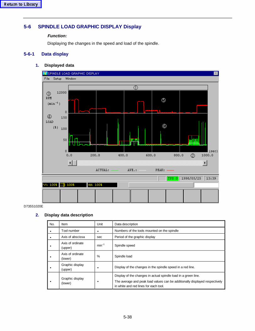
5-38
5-6 SPINDLE LOAD GRAPHIC DISPLAY Display
Function:
Displaying the changes in the speed and load of the spindle.
5-6-1 Data display
1. Displayed data
D735S1020E
2. Display data description
No. Item Unit Data description
• Tool number • Numbers of the tools mounted on the spindle
• Axis of abscissa sec Period of the graphic display
•Axis of ordinate(upper)
min–1 Spindle speed
•Axis of ordinate(lower)
% Spindle load
•Graphic display(upper)
• Display of the changes in the spindle speed in a red line.
•Graphic display(lower)
•
Display of the changes in actual spindle load in a green line.
The average and peak load values can be additionally displayed respectivelyin white and red lines for each tool.
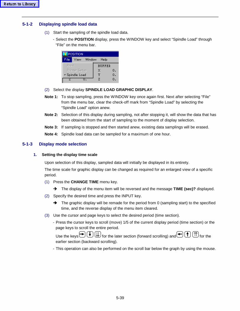
5-39
5-1-2 Displaying spindle load data
(1) Start the sampling of the spindle load data.
- Select the POSITION display, press the WINDOW key and select “Spindle Load” through“File” on the menu bar.
(2) Select the display SPINDLE LOAD GRAPHIC DISPLAY .
Note 1: To stop sampling, press the WINDOW key once again first. Next after selecting “File”from the menu bar, clear the check-off mark from “Spindle Load” by selecting the“Spindle Load” option anew.
Note 2: Selection of this display during sampling, not after stopping it, will show the data that hasbeen obtained from the start of sampling to the moment of display selection.
Note 3: If sampling is stopped and then started anew, existing data samplings will be erased.
Note 4: Spindle load data can be sampled for a maximum of one hour.
5-1-3 Display mode selection
1. Setting the display time scale
Upon selection of this display, sampled data will initially be displayed in its entirety.
The time scale for graphic display can be changed as required for an enlarged view of a specificperiod.
(1) Press the CHANGE TIME menu key.
Î The display of the menu item will be reversed and the message TIME (sec)? displayed.
(2) Specify the desired time and press the INPUT key.
Î The graphic display will be remade for the period from 0 (sampling start) to the specifiedtime, and the reverse display of the menu item cleared.
(3) Use the cursor and page keys to select the desired period (time section).
- Press the cursor keys to scroll (move) 1/5 of the current display period (time section) or thepage keys to scroll the entire period.
Use the keys for the later section (forward scrolling) and for theearlier section (backward scrolling).
- This operation can also be performed on the scroll bar below the graph by using the mouse.
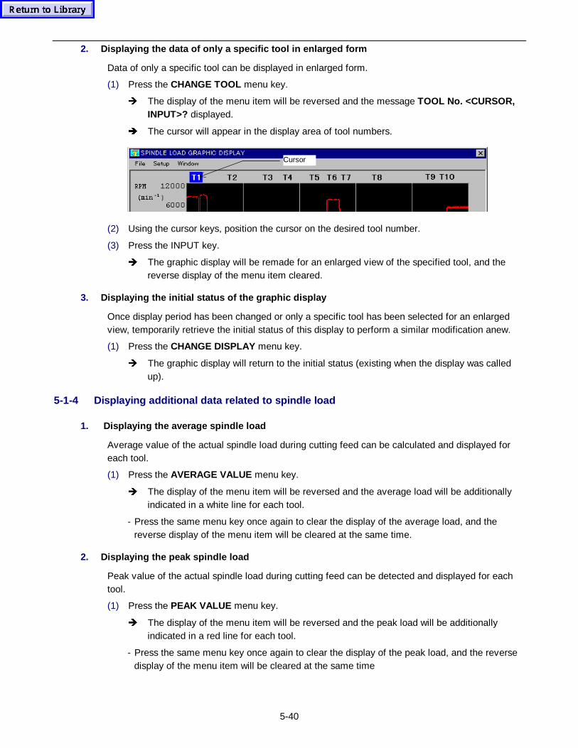
5-40
2. Displaying the data of only a specific tool in enlarged form
Data of only a specific tool can be displayed in enlarged form.
(1) Press the CHANGE TOOL menu key.
Î The display of the menu item will be reversed and the message TOOL No. <CURSOR,INPUT>? displayed.
Î The cursor will appear in the display area of tool numbers.
Cursor
(2) Using the cursor keys, position the cursor on the desired tool number.
(3) Press the INPUT key.
Î The graphic display will be remade for an enlarged view of the specified tool, and thereverse display of the menu item cleared.
3. Displaying the initial status of the graphic display
Once display period has been changed or only a specific tool has been selected for an enlargedview, temporarily retrieve the initial status of this display to perform a similar modification anew.
(1) Press the CHANGE DISPLAY menu key.
Î The graphic display will return to the initial status (existing when the display was calledup).
5-1-4 Displaying additional data related to spindle load
1. Displaying the average s pindle load
Average value of the actual spindle load during cutting feed can be calculated and displayed foreach tool.
(1) Press the AVERAGE VALUE menu key.
Î The display of the menu item will be reversed and the average load will be additionallyindicated in a white line for each tool.
- Press the same menu key once again to clear the display of the average load, and thereverse display of the menu item will be cleared at the same time.
2. Displaying the p eak spindle load
Peak value of the actual spindle load during cutting feed can be detected and displayed for eachtool.
(1) Press the PEAK VALUE menu key.
Î The display of the menu item will be reversed and the peak load will be additionallyindicated in a red line for each tool.
- Press the same menu key once again to clear the display of the peak load, and the reversedisplay of the menu item will be cleared at the same time
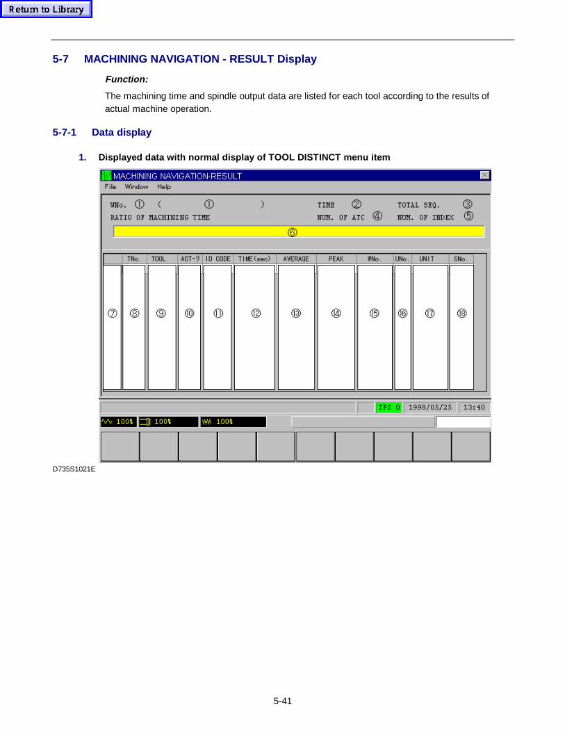
5-41
5-7 MACHINING NAVIGATION - RESULT Display
Function:
The machining time and spindle output data are listed for each tool according to the results ofactual machine operation.
5-7-1 Data display
1. Displayed data with normal display of T OOL DISTINCT menu item
D735S1021E
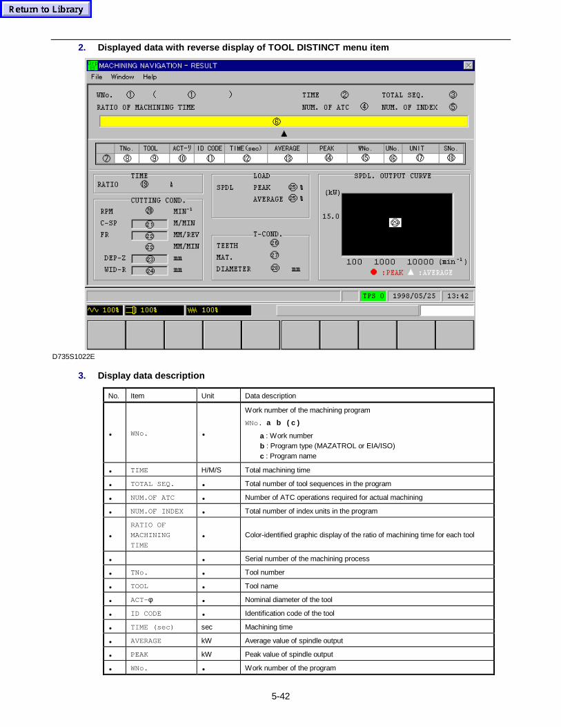
5-42
2. Displayed data with reverse display of T OOL DISTINCT menu item
D735S1022E
3. Display data description
No. Item Unit Data description
• WNo. •
Work number of the machining program
WNo. a b ( c )
a : Work numberb : Program type (MAZATROL or EIA/ISO)c : Program name
• TIME H/M/S Total machining time
• TOTAL SEQ. • Total number of tool sequences in the program
• NUM.OF ATC • Number of ATC operations required for actual machining
• NUM.OF INDEX • Total number of index units in the program
•
RATIO OF
MACHINING
TIME• Color-identified graphic display of the ratio of machining time for each tool
• • Serial number of the machining process
• TNo. • Tool number
• TOOL • Tool name
• ACT-φ • Nominal diameter of the tool
• ID CODE • Identification code of the tool
• TIME (sec) sec Machining time
• AVERAGE kW Average value of spindle output
• PEAK kW Peak value of spindle output
• WNo. • Work number of the program
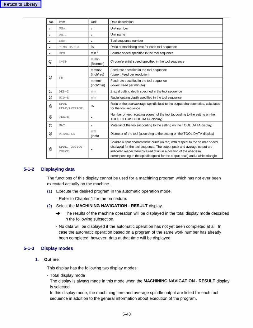
5-43
No. Item Unit Data description
• UNo. • Unit number
• UNIT • Unit name
• SNo. • Tool sequence number
• TIME RATIO % Ratio of machining time for each tool sequence
• RPM min–1 Spindle speed specified in the tool sequence
21 C-SPm/min(feet/min)
Circumferential speed specified in the tool sequence
mm/rev(inch/rev)
Feed rate specified in the tool sequence(upper: Feed per revolution)
22 FRmm/min(inch/min)
Feed rate specified in the tool sequence(lower: Feed per minute)
23 DEP-Z mm Z-axial cutting depth specified in the tool sequence
24 WID-R mm Radial cutting depth specified in the tool sequence
25SPDL
PEAK/AVERAGE%
Ratio of the peak/average spindle load to the output characteristics, calculatedfor the tool sequence
26 TEETH •Number of teeth (cutting edges) of the tool (according to the setting on theTOOL FILE or TOOL DATA display)
27 MAT. • Material of the tool (according to the setting on the TOOL DATA display)
28 DIAMETERmm(inch)
Diameter of the tool (according to the setting on the TOOL DATA display)
29SPDL. OUTPUT
CURVE•
Spindle output characteristic curve (in red) with respect to the spindle speed,displayed for the tool sequence. The output peak and average output areindicated respectively by a red disk (in a position of the abscissacorresponding to the spindle speed for the output peak) and a white triangle.
5-1-2 Displaying data
The functions of this display cannot be used for a machining program which has not ever beenexecuted actually on the machine.
(1) Execute the desired program in the automatic operation mode.
- Refer to Chapter 1 for the procedure.
(2) Select the MACHINING NAVIGATION - RESULT display.
Î The results of the machine operation will be displayed in the total display mode describedin the following subsection.
- No data will be displayed if the automatic operation has not yet been completed at all. Incase the automatic operation based on a program of the same work number has alreadybeen completed, however, data at that time will be displayed.
5-1-3 Display modes
1. Outline
This display has the following two display modes:
- Total display modeThe display is always made in this mode when the MACHINING NAVIGATION - RESULT displayis selected.In this display mode, the machining time and average spindle output are listed for each toolsequence in addition to the general information about execution of the program.
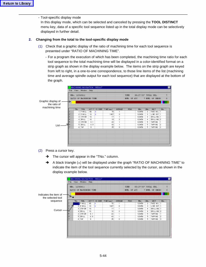
5-44
- Tool-specific display modeIn this display mode, which can be selected and canceled by pressing the TOOL DISTINCTmenu key, data of a specific tool sequence listed up in the total display mode can be selectivelydisplayed in further detail.
2. Changing from the total to the tool-specific display mode
(1) Check that a graphic display of the ratio of machining time for each tool sequence ispresented under “RATIO OF MACHINING TIME”.
- For a program the execution of which has been completed, the machining time ratio for eachtool sequence to the total machining time will be displayed in a color-identified format on astrip graph as shown in the display example below. The items on the strip graph are keyedfrom left to right, in a one-to-one correspondence, to those line items of the list (machiningtime and average spindle output for each tool sequence) that are displayed at the bottom ofthe graph.
Graphic display ofthe ratio of
machining time
List
(2) Press a cursor key.
Î The cursor will appear in the “TNo.” column.
Î A black triangle (• ) will be displayed under the graph “RATIO OF MACHINING TIME” toindicate the item of the tool sequence currently selected by the cursor, as shown in thedisplay example below.
Indicates the item ofthe selected tool
sequence
Cursor

5-45
(3) Using the cursor keys, position the cursor on the desired tool sequence number.
Î The black triangle will move correspondingly with the cursor so that the ratio of themachining time of the specific tool sequence to the total machining time can be visuallychecked.
(4) Press the TOOL DISTINCT menu key.
Î The display of the menu item will be reversed and the display contents will be changedfor a detailed view of the specified tool.
- Press the same menu key once again, and the total display mode will be retrieved and thereverse display of the menu item cleared.

5-46
- NOTE -
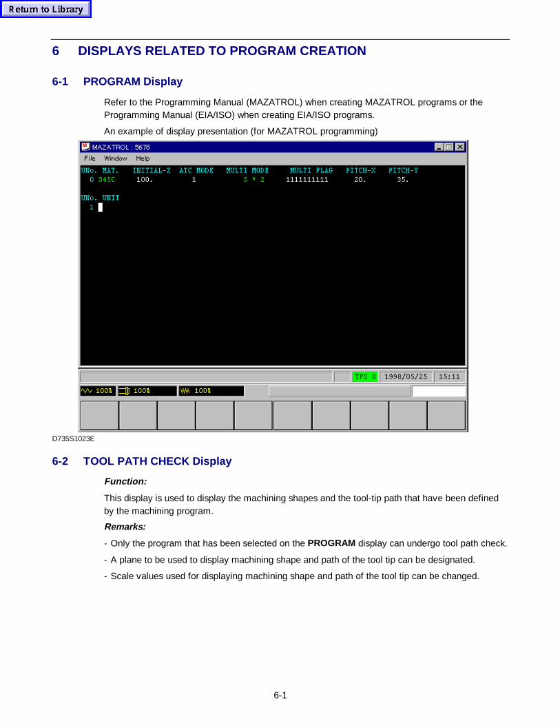
6-1
6 DISPLAYS RELATED TO PROGRAM CREATION
6-1 PROGRAM Display
Refer to the Programming Manual (MAZATROL) when creating MAZATROL programs or theProgramming Manual (EIA/ISO) when creating EIA/ISO programs.
An example of display presentation (for MAZATROL programming)
D735S1023E
6-2 TOOL PATH CHECK Display
Function:
This display is used to display the machining shapes and the tool-tip path that have been definedby the machining program.
Remarks:
- Only the program that has been selected on the PROGRAM display can undergo tool path check.
- A plane to be used to display machining shape and path of the tool tip can be designated.
- Scale values used for displaying machining shape and path of the tool tip can be changed.
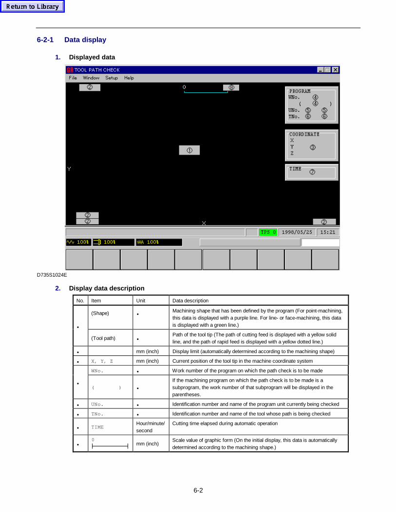
6-2
6-2-1 Data display
1. Displayed data
D735S1024E
2. Display data description
No. Item Unit Data description
(Shape) •Machining shape that has been defined by the program (For point-machining,this data is displayed with a purple line. For line- or face-machining, this datais displayed with a green line.)•
(Tool path) •Path of the tool tip (The path of cutting feed is displayed with a yellow solidline, and the path of rapid feed is displayed with a yellow dotted line.)
• mm (inch) Display limit (automatically determined according to the machining shape)
• X, Y, Z mm (inch) Current position of the tool tip in the machine coordinate system
WNo. • Work number of the program on which the path check is to be made
•( ) •
If the machining program on which the path check is to be made is asubprogram, the work number of that subprogram will be displayed in theparentheses.
• UNo. • Identification number and name of the program unit currently being checked
• TNo. • Identification number and name of the tool whose path is being checked
• TIMEHour/minute/second
Cutting time elapsed during automatic operation
•0
mm (inch)Scale value of graphic form (On the initial display, this data is automaticallydetermined according to the machining shape.)
6-3
6-1-2 Displaying machining shape
(1) Press the PART SHAPE menu key.
Î This will cause the display status of PART SHAPE to reverse and the machining shapesthat have been defined by the program to be displayed continuously.
- Point-machining shapes will each be displayed with a purple line, and line- or face-machining shapes will each be displayed with a green line.
- After displaying machining shapes, the reverse-display status of PART SHAPE will bereleased automatically.
Note 1: Depression of the PLANE CHANGE menu key allows either a plane or a 3-D view to beselected for display of a machining shape(s). For the selecting procedure, see thedescription of display operation (4-2-3 Plane select ) that is given in Section 4-2 TRACEDisplay .If plane-select operation has not been carried out, the machining shape available on theXY plane will be displayed.
Note 2: Depression of the SCALE CHANGE menu key allows display of machining shapes inenlarged or reduced size. In addition, the 3-D display viewpoint can be changed if the 3-Dview of a machining shape has been selected by plane selection operation. For thechanging procedure, see the description of display operation (4-2-4 Change of scalevalues ) that is given in Section 4-2 TRACE Display.If this operation has not been carried out, machining shapes will be displayed at theautomatically determined scaling factor.
6-1-3 Displaying tool-tip path
1. Continuous display
(1) Press the PATH CONTINUE menu key.
Î This will cause the display status of PATH CONTINUE to reverse and the tool-tip path tobe displayed continuously.
- The tool-tip path for cutting feed will be displayed with a yellow solid line, and the tool-tippath for rapid feed will be displayed with a yellow dotted line.
- After display of the tool-tip path, the reverse-display status of PATH CONTINUE will bereleased automatically.
2. Intermittent display
(1) Press the PATH STEP menu key.
Î This will cause the display status of PATH STEP to reverse and the tool-tip path to bedisplayed step by step by each depression of the menu key.
- The tool-tip path for cutting feed will be displayed with a yellow solid line, and the tool-tippath for rapid feed will be displayed with a yellow dotted line.
- After display of the entire tool-tip path, the reverse-display status of PATH STEP will bereleased automatically.
6-4
6-1-4 Restarting tool path check
Tool path checks can be carried out in the middle of the program.
(1) Press the menu selector key.
(2) Press the PATH RESTART menu key.
Î The display status of the menu will then reverse and a restart data setting window will beopened.
(3) Designate the restarting position of tool path checking.
- How to specify the restarting position of tool path checking is the same as for the restart inthe automatic operation mode.See the Operating Manual, Part 4, Subsection 1-2-2 Restart operation , for further details.
(4) Press the PATH CONTINUE or PATH STEP menu key.
Î Tool path checking will then start from the designated position.
6-1-5 Block skip
Any block of the EIA/ISO program can be skipped to check the tool path.
(1) Press the menu selector key.
(2) Press the BLOCK SKIP menu key.
(3) Press the PATH CONTINUE or PATH STEP menu key.
How to specify the blocks to be skipped is the same as for the blocks in the automatic operationmode. See the Operating Manual, Part 4, Section 2-5 Block skip , for further details.
6-1-6 Other menu functions
1. Depression of the SHAPE ERASE menu key causes erasure of the particular machiningshape.Erasure of the machining shape currently being displayed can also be made by pressing thismenu key while the machining shape is being drawn on the display.
2. Depression of the PATH ERASE menu key causes erasure of the tool-tip path.Erasure of the tool-tip path can also be made by pressing this menu key while the tool-tip pathis being drawn on the display.
3. The tool-tip path continuous display mode can be changed over to the intermittent displaymode if the PATH STEP menu key is pressed while the tool-tip path is being displayedcontinuously (i.e., while PATH CONTINUE remains on the display in reverse form).
4. The tool-tip path intermittent display mode can be changed over to the continuous displaymode if the PATH CONTINUE menu key is pressed while the tool-tip path is being displayedintermittently (i.e., while PATH STEP remains on the display in reverse form).
5. It is possible for the display of machining shapes and tool-tip path to be aborted by pressingthe clear key.This is not possible, however, with the reset key.
6. If the menu display status is changed to reverse form by pressing the STORE menu key, theshape data and the tool-tip path data will be preserved even after the display has beenchanged over to another display.
7. When the PROGRAM menu key is pressed, the display will change over to the PROGRAMdisplay.
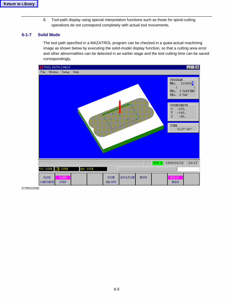
6-5
8. Tool-path display using special interpolation functions such as those for spiral-cuttingoperations do not correspond completely with actual tool movements.
6-1-7 Solid Mode
The tool path specified in a MAZATROL program can be checked in a quasi-actual machiningimage as shown below by executing the solid-model display function, so that a cutting area errorand other abnormalities can be detected in an earlier stage and the test cutting time can be savedcorrespondingly.
D735S1025E
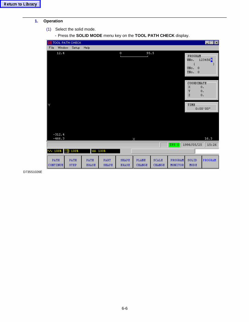
6-6
1. Operation
(1) Select the solid mode.
- Press the SOLID MODE menu key on the TOOL PATH CHECK display.
D735S1026E
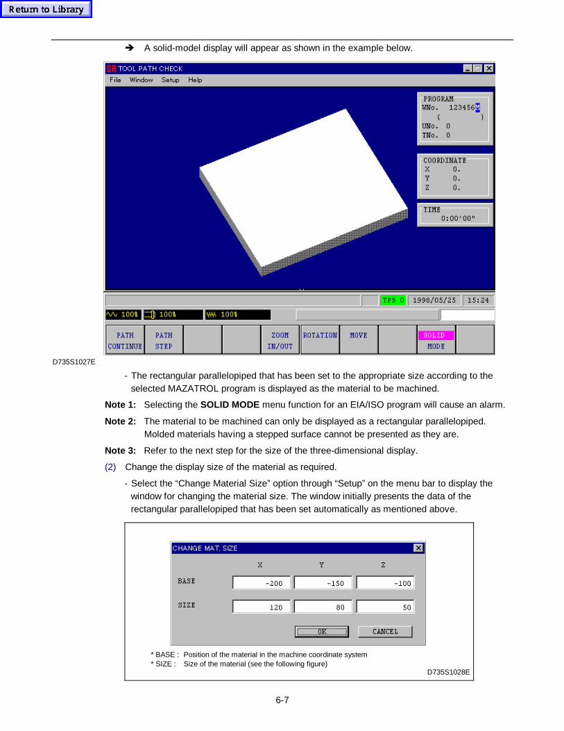
6-7
Î A solid-model display will appear as shown in the example below.
D735S1027E
- The rectangular parallelopiped that has been set to the appropriate size according to theselected MAZATROL program is displayed as the material to be machined.
Note 1: Selecting the SOLID MODE menu function for an EIA/ISO program will cause an alarm.
Note 2: The material to be machined can only be displayed as a rectangular parallelopiped.Molded materials having a stepped surface cannot be presented as they are.
Note 3: Refer to the next step for the size of the three-dimensional display.
(2) Change the display size of the material as required.
- Select the “Change Material Size” option through “Setup” on the menu bar to display thewindow for changing the material size. The window initially presents the data of therectangular parallelopiped that has been set automatically as mentioned above.
D735S1028E
* BASE : Position of the material in the machine coordinate system* SIZE : Size of the material (see the following figure)
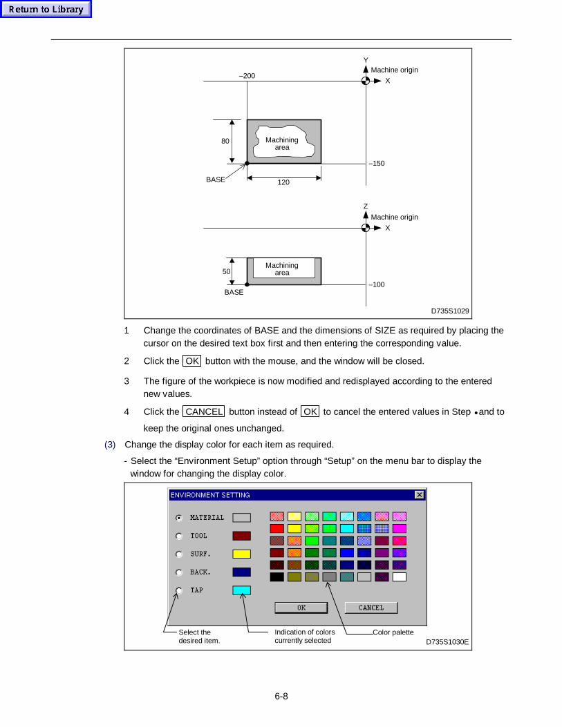
6-8
120
–150
–200
80
BASE
Machine origin
X
Y
Machiningarea
D735S1029
–100
50
BASE
Machine origin
X
Z
Machiningarea
1 Change the coordinates of BASE and the dimensions of SIZE as required by placing thecursor on the desired text box first and then entering the corresponding value.
2 Click the OK button with the mouse, and the window will be closed.
3 The figure of the workpiece is now modified and redisplayed according to the enterednew values.
4 Click the CANCEL button instead of OK to cancel the entered values in Step • and to
keep the original ones unchanged.
(3) Change the display color for each item as required.
- Select the “Environment Setup” option through “Setup” on the menu bar to display thewindow for changing the display color.
D735S1030ESelect thedesired item.
Indication of colorscurrently selected
Color palette
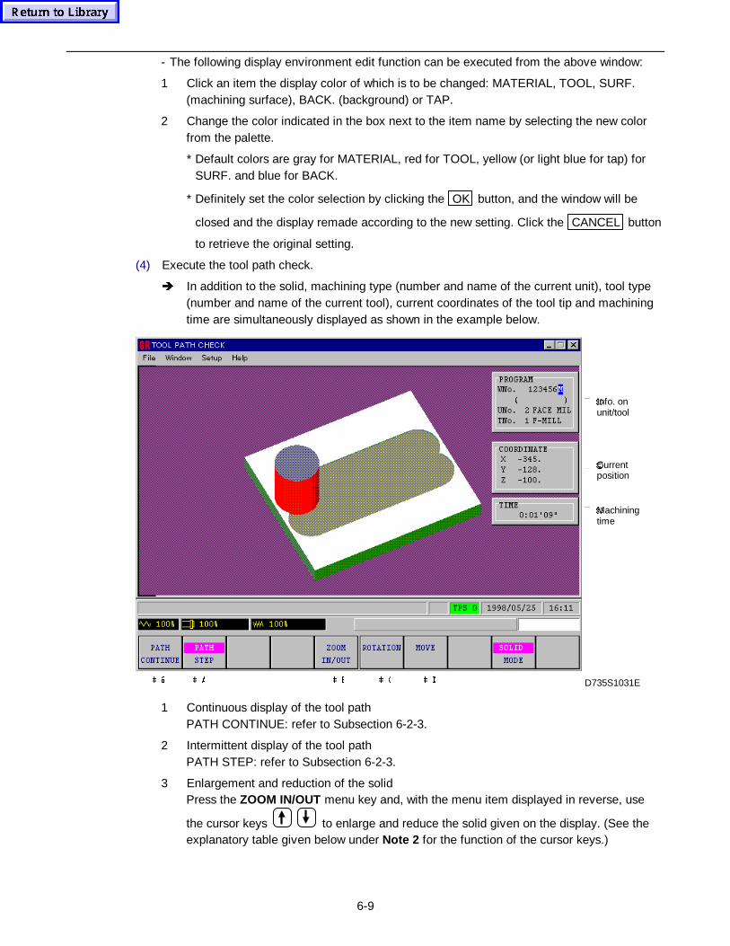
6-9
- The following display environment edit function can be executed from the above window:
1 Click an item the display color of which is to be changed: MATERIAL, TOOL, SURF.(machining surface), BACK. (background) or TAP.
2 Change the color indicated in the box next to the item name by selecting the new colorfrom the palette.
* Default colors are gray for MATERIAL, red for TOOL, yellow (or light blue for tap) forSURF. and blue for BACK.
* Definitely set the color selection by clicking the OK button, and the window will be
closed and the display remade according to the new setting. Click the CANCEL button
to retrieve the original setting.
(4) Execute the tool path check.
Î In addition to the solid, machining type (number and name of the current unit), tool type(number and name of the current tool), current coordinates of the tool tip and machiningtime are simultaneously displayed as shown in the example below.
� �Machiningtime
� �Currentposition
� �Info. onunit/tool
D735S1031EÂ 'Â &Â %Â $Â #
1 Continuous display of the tool pathPATH CONTINUE: refer to Subsection 6-2-3.
2 Intermittent display of the tool pathPATH STEP: refer to Subsection 6-2-3.
3 Enlargement and reduction of the solidPress the ZOOM IN/OUT menu key and, with the menu item displayed in reverse, use
the cursor keys to enlarge and reduce the solid given on the display. (See theexplanatory table given below under Note 2 for the function of the cursor keys.)
6-10
4 Rotation of the solidPress the ROTATION menu key and, with the menu item displayed in reverse, use the
cursor keys to rotate the solid given on the display. (See theexplanatory table given below under Note 2 for the function of the cursor keys.)
5 Movement of the solidPress the MOVE menu key and, with the menu item displayed in reverse, use the cursor
keys to move (shift) the solid given on the display. (See theexplanatory table given below under Note 2 for the function of the cursor keys.)
Note 1: Even during the tool path check, the functions of the menu items ZOOM IN/OUT,ROTATION and MOVE are effective to simultaneously execute the operations • , • and • .
Note 2: The function of the cursor keys for the modes ZOOM IN/OUT, ROTATION and MOVE isexplained in the following table.
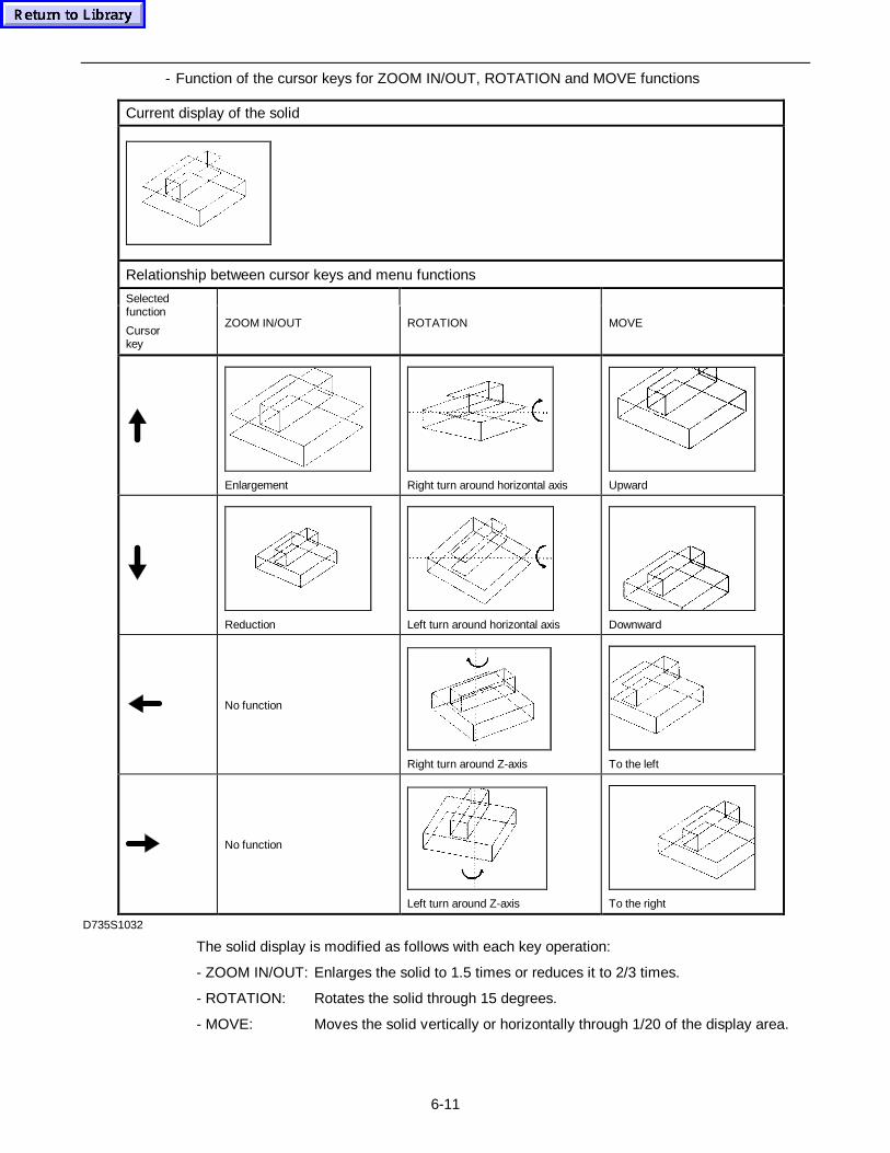
6-11
- Function of the cursor keys for ZOOM IN/OUT, ROTATION and MOVE functions
Current display of the solid
Relationship between cursor keys and menu functions
Selectedfunction
Cursorkey
ZOOM IN/OUT ROTATION MOVE
Enlargement Right turn around horizontal axis Upward
Reduction Left turn around horizontal axis Downward
No function
Right turn around Z-axis To the left
No function
Left turn around Z-axis To the right
D735S1032
The solid display is modified as follows with each key operation:
- ZOOM IN/OUT: Enlarges the solid to 1.5 times or reduces it to 2/3 times.
- ROTATION: Rotates the solid through 15 degrees.
- MOVE: Moves the solid vertically or horizontally through 1/20 of the display area.
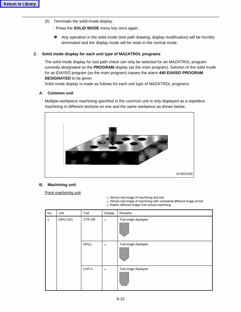
6-12
(5) Terminate the solid-mode display.
- Press the SOLID MODE menu key once again.
Î Any operation in the solid mode (tool path drawing, display modification) will be forciblyterminated and the display mode will be reset to the normal mode.
2. Solid mode display for each unit type of MAZATROL prog rams
The solid mode display for tool path check can only be selected for an MAZATROL programcurrently designated on the PROGRAM display (as the main program). Selction of the solid modefor an EIA/ISO program (as the main program) causes the alarm 440 EIA/ISO PROGRAMDESIGNATED to be given.Solid mode display is made as follows for each unit type of MAZATROL programs:
A. Common unit
Multiple-workpiece machining specified in the common unit is only displayed as a repetitivemachining in different sections on one and the same workpiece as shown below.
D735S1035
B. Machining unit
Point machining unit• : Almost real image of machining and tool• : Almost real image of machining with somewhat different image of tool• : Rather different image from actual machining
No. Unit Tool Display Remarks
CTR-DR • Tool image displayed
DRILL • Tool image displayed
1 DRILLING
CHF-C • Tool image displayed
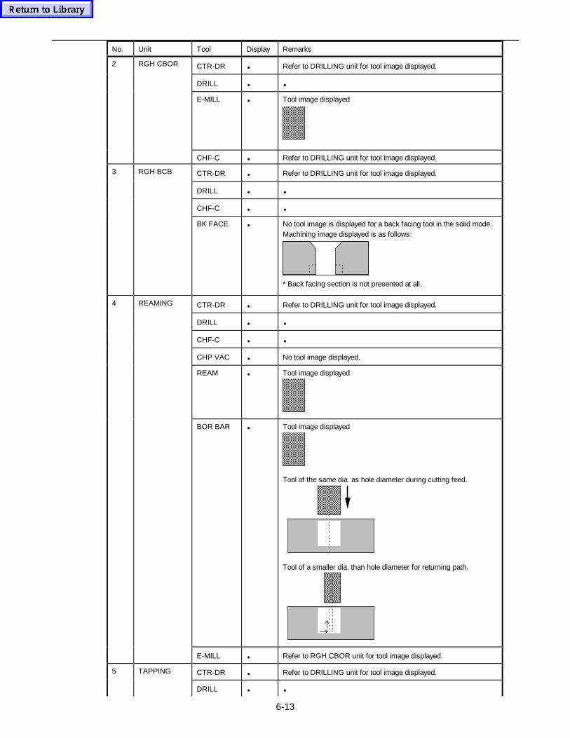
6-13
No. Unit Tool Display Remarks
CTR-DR • Refer to DRILLING unit for tool image displayed.
DRILL • •
E-MILL • Tool image displayed
2 RGH CBOR
CHF-C • Refer to DRILLING unit for tool image displayed.
CTR-DR • Refer to DRILLING unit for tool image displayed.
DRILL • •
CHF-C • •
3 RGH BCB
BK FACE • No tool image is displayed for a back facing tool in the solid mode.Machining image displayed is as follows:
* Back facing section is not presented at all.
CTR-DR • Refer to DRILLING unit for tool image displayed.
DRILL • •
CHF-C • •
CHP VAC • No tool image displayed.
REAM • Tool image displayed
BOR BAR • Tool image displayed
Tool of the same dia. as hole diameter during cutting feed.
Tool of a smaller dia. than hole diameter for returning path.
4 REAMING
E-MILL • Refer to RGH CBOR unit for tool image displayed.
CTR-DR • Refer to DRILLING unit for tool image displayed.5 TAPPING
DRILL • •
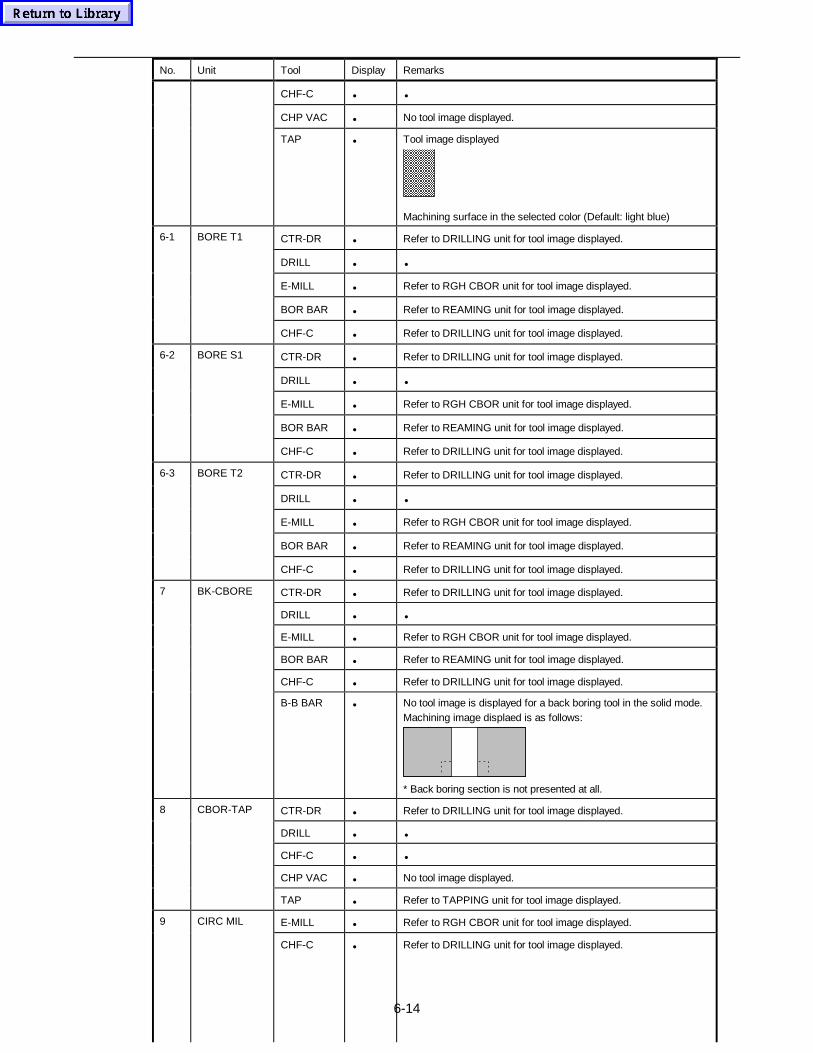
6-14
No. Unit Tool Display Remarks
CHF-C • •
CHP VAC • No tool image displayed.
TAP • Tool image displayed
Machining surface in the selected color (Default: light blue)
CTR-DR • Refer to DRILLING unit for tool image displayed.
DRILL • •
E-MILL • Refer to RGH CBOR unit for tool image displayed.
BOR BAR • Refer to REAMING unit for tool image displayed.
6-1 BORE T1
CHF-C • Refer to DRILLING unit for tool image displayed.
CTR-DR • Refer to DRILLING unit for tool image displayed.
DRILL • •
E-MILL • Refer to RGH CBOR unit for tool image displayed.
BOR BAR • Refer to REAMING unit for tool image displayed.
6-2 BORE S1
CHF-C • Refer to DRILLING unit for tool image displayed.
CTR-DR • Refer to DRILLING unit for tool image displayed.
DRILL • •
E-MILL • Refer to RGH CBOR unit for tool image displayed.
BOR BAR • Refer to REAMING unit for tool image displayed.
6-3 BORE T2
CHF-C • Refer to DRILLING unit for tool image displayed.
CTR-DR • Refer to DRILLING unit for tool image displayed.
DRILL • •
E-MILL • Refer to RGH CBOR unit for tool image displayed.
BOR BAR • Refer to REAMING unit for tool image displayed.
CHF-C • Refer to DRILLING unit for tool image displayed.
7 BK-CBORE
B-B BAR • No tool image is displayed for a back boring tool in the solid mode.Machining image displaed is as follows:
* Back boring section is not presented at all.
CTR-DR • Refer to DRILLING unit for tool image displayed.
DRILL • •
CHF-C • •
CHP VAC • No tool image displayed.
8 CBOR-TAP
TAP • Refer to TAPPING unit for tool image displayed.
E-MILL • Refer to RGH CBOR unit for tool image displayed.9 CIRC MIL
CHF-C • Refer to DRILLING unit for tool image displayed.
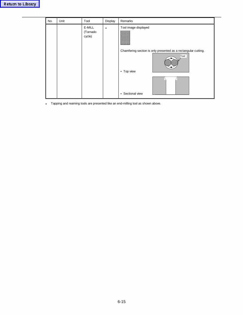
6-15
No. Unit Tool Display Remarks
E-MILL(Tornadocycle)
• Tool image displayed
Chamfering section is only presented as a rectangular cutting.
• Top view
Tool
• Sectional view
• Tapping and reaming tools are presented like an end-milling tool as shown above.
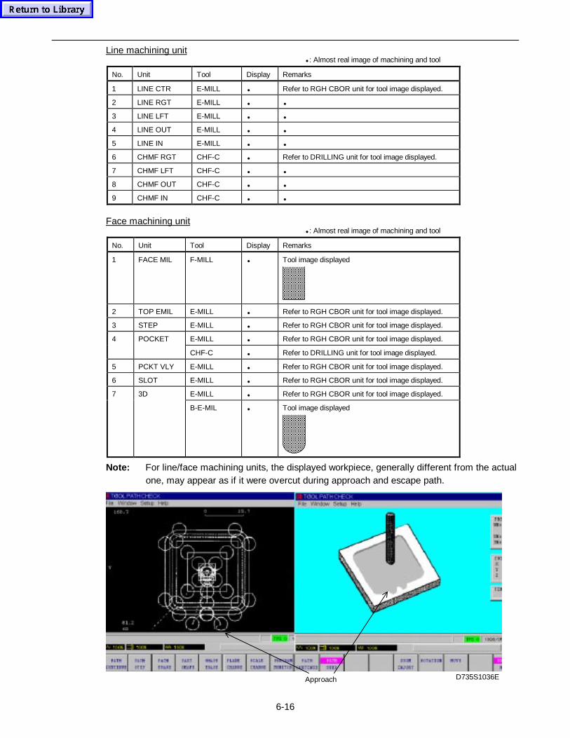
6-16
Line machining unit• : Almost real image of machining and tool
No. Unit Tool Display Remarks
1 LINE CTR E-MILL • Refer to RGH CBOR unit for tool image displayed.
2 LINE RGT E-MILL • •
3 LINE LFT E-MILL • •
4 LINE OUT E-MILL • •
5 LINE IN E-MILL • •
6 CHMF RGT CHF-C • Refer to DRILLING unit for tool image displayed.
7 CHMF LFT CHF-C • •
8 CHMF OUT CHF-C • •
9 CHMF IN CHF-C • •
Face machining unit• : Almost real image of machining and tool
No. Unit Tool Display Remarks
1 FACE MIL F-MILL • Tool image displayed
2 TOP EMIL E-MILL • Refer to RGH CBOR unit for tool image displayed.
3 STEP E-MILL • Refer to RGH CBOR unit for tool image displayed.
E-MILL • Refer to RGH CBOR unit for tool image displayed.4 POCKET
CHF-C • Refer to DRILLING unit for tool image displayed.
5 PCKT VLY E-MILL • Refer to RGH CBOR unit for tool image displayed.
6 SLOT E-MILL • Refer to RGH CBOR unit for tool image displayed.
E-MILL • Refer to RGH CBOR unit for tool image displayed.7 3D
B-E-MIL • Tool image displayed
Note: For line/face machining units, the displayed workpiece, generally different from the actualone, may appear as if it were overcut during approach and escape path.
Approach D735S1036E
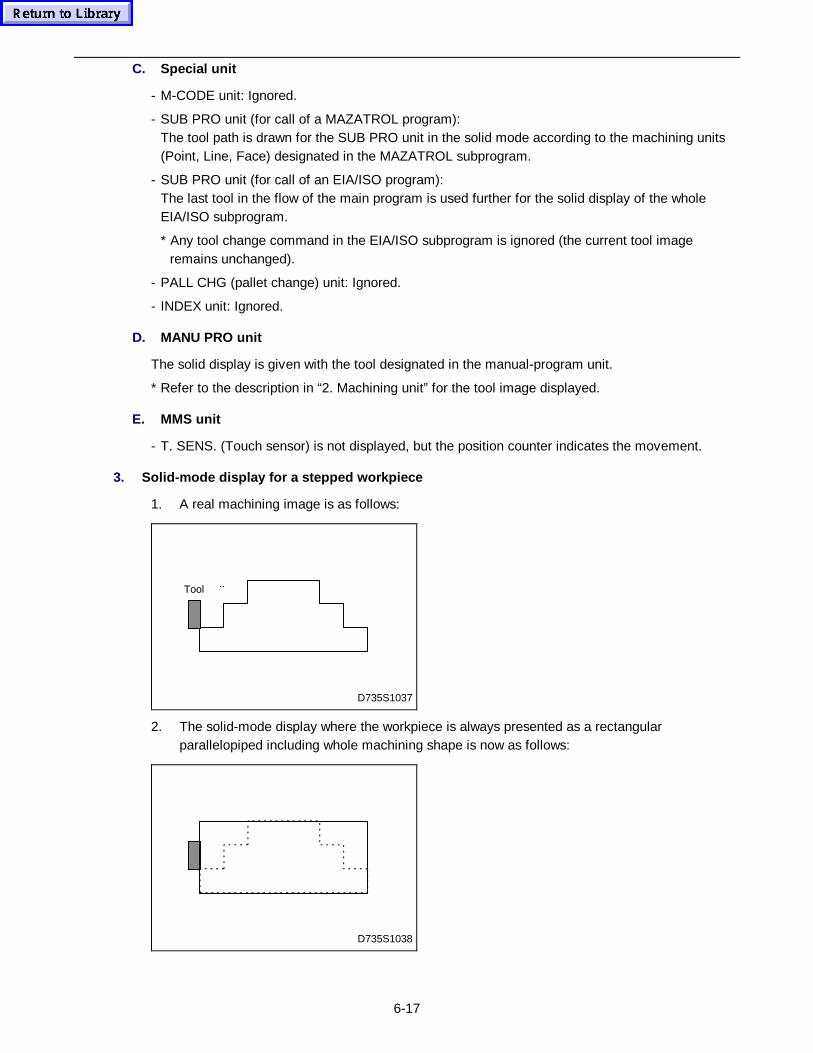
6-17
C. Special unit
- M-CODE unit: Ignored.
- SUB PRO unit (for call of a MAZATROL program):The tool path is drawn for the SUB PRO unit in the solid mode according to the machining units(Point, Line, Face) designated in the MAZATROL subprogram.
- SUB PRO unit (for call of an EIA/ISO program):The last tool in the flow of the main program is used further for the solid display of the wholeEIA/ISO subprogram.
* Any tool change command in the EIA/ISO subprogram is ignored (the current tool imageremains unchanged).
- PALL CHG (pallet change) unit: Ignored.
- INDEX unit: Ignored.
D. MANU PRO unit
The solid display is given with the tool designated in the manual-program unit.
* Refer to the description in “2. Machining unit” for the tool image displayed.
E. MMS unit
- T. SENS. (Touch sensor) is not displayed, but the position counter indicates the movement.
3. Solid-mode display for a stepped workpiece
1. A real machining image is as follows:
D735S1037
Tool� �
2. The solid-mode display where the workpiece is always presented as a rectangularparallelopiped including whole machining shape is now as follows:
D735S1038
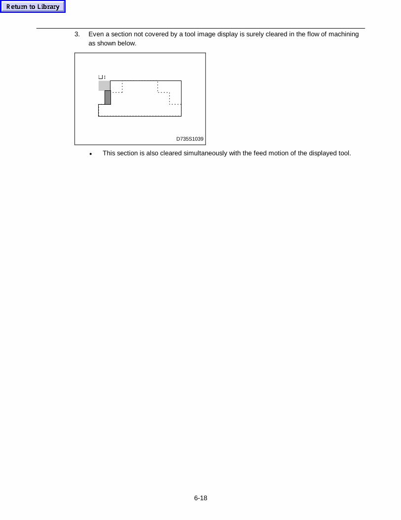
6-18
3. Even a section not covered by a tool image display is surely cleared in the flow of machiningas shown below.
D735S1039
�è
• This section is also cleared simultaneously with the feed motion of the displayed tool.
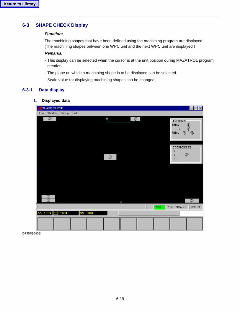
6-19
6-3 SHAPE CHECK Display
Function:
The machining shapes that have been defined using the machining program are displayed.(The machining shapes between one WPC unit and the next WPC unit are displayed.)
Remarks:
- This display can be selected when the cursor is at the unit position during MAZATROL programcreation.
- The plane on which a machining shape is to be displayed can be selected.
- Scale value for displaying machining shapes can be changed.
6-3-1 Data display
1. Displayed data
D735S1040E
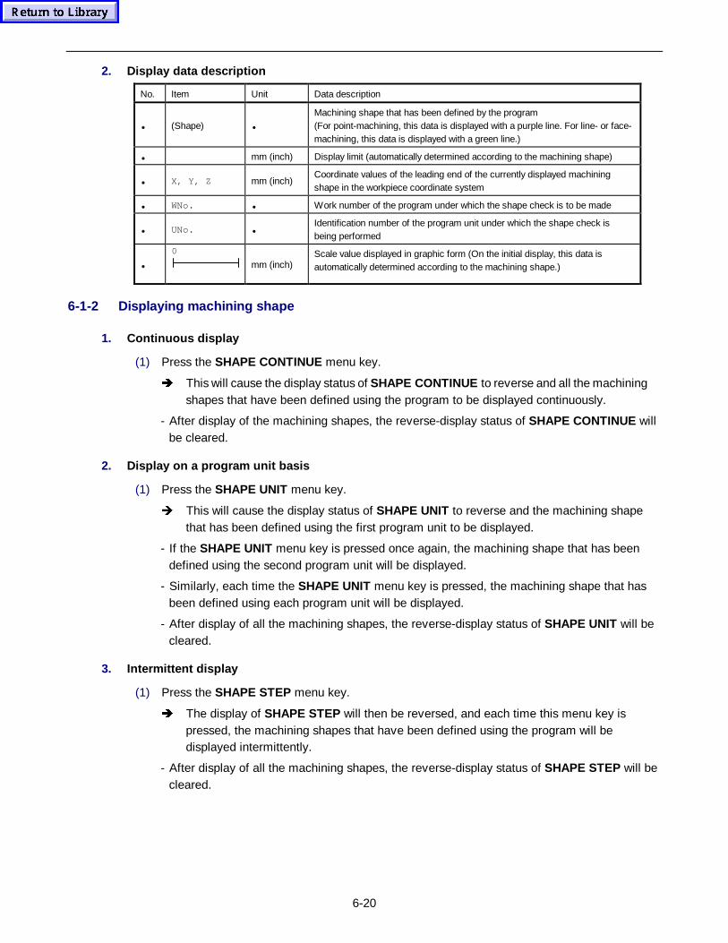
6-20
2. Display data description
No. Item Unit Data description
• (Shape) •
Machining shape that has been defined by the program(For point-machining, this data is displayed with a purple line. For line- or face-machining, this data is displayed with a green line.)
• mm (inch) Display limit (automatically determined according to the machining shape)
• X, Y, Z mm (inch)Coordinate values of the leading end of the currently displayed machiningshape in the workpiece coordinate system
• WNo. • Work number of the program under which the shape check is to be made
• UNo. •Identification number of the program unit under which the shape check isbeing performed
•
0
mm (inch)Scale value displayed in graphic form (On the initial display, this data isautomatically determined according to the machining shape.)
6-1-2 Displaying machining shape
1. Continuous display
(1) Press the SHAPE CONTINUE menu key.
Î This will cause the display status of SHAPE CONTINUE to reverse and all the machiningshapes that have been defined using the program to be displayed continuously.
- After display of the machining shapes, the reverse-display status of SHAPE CONTINUE willbe cleared.
2. Display on a program unit basis
(1) Press the SHAPE UNIT menu key.
Î This will cause the display status of SHAPE UNIT to reverse and the machining shapethat has been defined using the first program unit to be displayed.
- If the SHAPE UNIT menu key is pressed once again, the machining shape that has beendefined using the second program unit will be displayed.
- Similarly, each time the SHAPE UNIT menu key is pressed, the machining shape that hasbeen defined using each program unit will be displayed.
- After display of all the machining shapes, the reverse-display status of SHAPE UNIT will becleared.
3. Intermittent display
(1) Press the SHAPE STEP menu key.
Î The display of SHAPE STEP will then be reversed, and each time this menu key ispressed, the machining shapes that have been defined using the program will bedisplayed intermittently.
- After display of all the machining shapes, the reverse-display status of SHAPE STEP will becleared.
6-21
6-1-3 Other menu functions
1. If the PLANE CHANGE menu key is pressed, it becomes possible to select the plane or 3-Dview on which machining shapes are to be displayed. For details of the selecting procedure,see the Subsection 4-2-3 Plane select that is given in Section 4-2 TRACE Display . If theplane select is not carried out, the machining shape available on the XY plane will bedisplayed.
2. If the SCALE CHANGE menu key is pressed, it becomes possible to display machiningshapes in enlarged or reduced size. In addition, the 3-D display viewpoint can be changed if a3-D view has been selected during plane-select operation. For details of these operations, seethe Subsection 4-2-4 Change of the scaling factor that is given in Section 4-2 TRACEDisplay . If this operation has not been carried out, then machining shapes will be displayed atthe automatically determined scaling factor.
3. Pressing the SHAPE ERASE menu key causes erasure of the machining shape. In addition,by pressing this menu key, it is possible to erase the machining shape currently beingdisplayed.
4. If the menu display status is changed to reverse form by pressing the STORE menu key, theshape data will be preserved even after the display has been changed over to another display.
5. Pressing the PROGRAM menu key causes the current display to change over to thePROGRAM display.
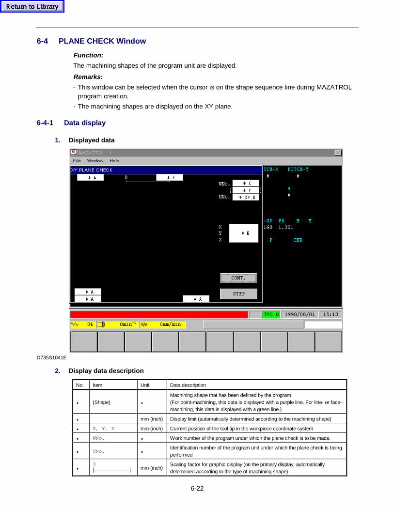
6-22
6-4 PLANE CHECK Window
Function:
The machining shapes of the program unit are displayed.
Remarks:
- This window can be selected when the cursor is on the shape sequence line during MAZATROLprogram creation.
- The machining shapes are displayed on the XY plane.
6-4-1 Data display
1. Displayed data
 %
 $ $
 $
 '  '
 &
 &
 ( $
D735S1041E
2. Display data description
No. Item Unit Data description
• (Shape) •
Machining shape that has been defined by the program(For point-machining, this data is displayed with a purple line. For line- or face-machining, this data is displayed with a green line.)
• mm (inch) Display limit (automatically determined according to the machining shape)
• X, Y, Z mm (inch) Current position of the tool tip in the workpiece coordinate system
• WNo. • Work number of the program under which the plane check is to be made.
• UNo. •Identification number of the program unit under which the plane check is beingperformed
•0
mm (inch)Scaling factor for graphic display (on the primary display, automaticallydetermined according to the type of machining shape)
6-23
6-1-2 Displaying machining shape
Press the PLANE CHECK menu key to display the PLANE CHECK window.
1. Continuous display
(1) Operate the cursor keys to move the foucus onto the button CONT. in the window and press
the INPUT key.
Î The machining shapes that have been defined in the shape sequence line where thecursor has been blinking on the PROGRAM display will be displayed continuously.
2. Intermittent display
(1) Operate the cursor keys to move the foucus onto the button STEP in the window and press
the INPUT key.
Î Each time the INPUT key is pressed, the machining shapes that have been defined in theshape sequence line where the cursor has been blinking on the PROGRAM display willbe displayed intermittently.
6-1-3 Others
1. Only the machining shape on the XY plane can be indicated in the PLANE CHECK window.
2. The scaling factor for the PLANE CHECK window is automatically determined according tothe machining shape. Thus, the operator cannot change the scaling factor.
3. To abort the display of machining shapes, press the CLEAR key.
4. Press the PLANE CHECK menu key anew to close the window.
6-5 SECTION CHECK Window
Function:
The machining shapes that have been defined on the point-machining shape sequence line aredisplayed in sectional view.
Remarks:
- This window can be selected when the cursor remains on the point-machining shape sequenceline during MAZATROL program creation.
- The sectional shapes are displayed on the XZ plane.
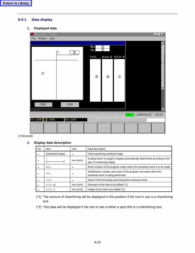
6-24
6-5-1 Data display
1. Displayed data
D735S1042E
2. Display data description
No. Item Unit Data description
• (Sectional shape) • Point-machining sectional shape
•0
mm (inch)Scaling factor for graphic display (automatically determined according to thetype of machining shape)
• WNo. • Work number of the program under which the sectional check is to be made
• UNo. •Identification number and name of the program unit under which thesectional check is being performed
• TOOL • Name of the tool being used during the sectional check
• HOLE-φ mm (inch) Diameter of the hole to be drilled (*1)
• HOLE-H mm (inch) Height of the hole to be drilled (*2)
(*1) The amount of chamfering will be displayed in this position if the tool in use is a chamferingtool.
(*2) This data will be displayed if the tool in use is either a spot drill or a chamfering tool.
6-25
6-1-2 Displaying sectional shapes
Press the SECTION CHECK menu key to display the SECTION CHECK window.
1. Continuous display
(1) Operate the cursor keys to move the foucus onto the button CONT. in the window and press
the INPUT key.
- The point-machining sectional shapes that have been defined in the line where the cursor isblinking on the PROGRAM display will be indicated continuously.
2. Intermittent display
(1) Operate the cursor keys to move the foucus onto the button STEP in the window and press
the INPUT key.
- Each time the INPUT key is pressed, the point-machining sectional shapes that have beendefined in the line where the cursor is blinking on the PROGRAM display will be indicatedintermittently.
6-1-3 Others
1. Only the sectional shape on the XZ plane can be indicated on the SECTION CHECK window.
2. The scaling factor for the SECTION CHECK window is automatically determined according tothe machining shape. Thus, the operator cannot change the scaling factor.
3. Press the SECTION CHECK menu key anew to close the window.
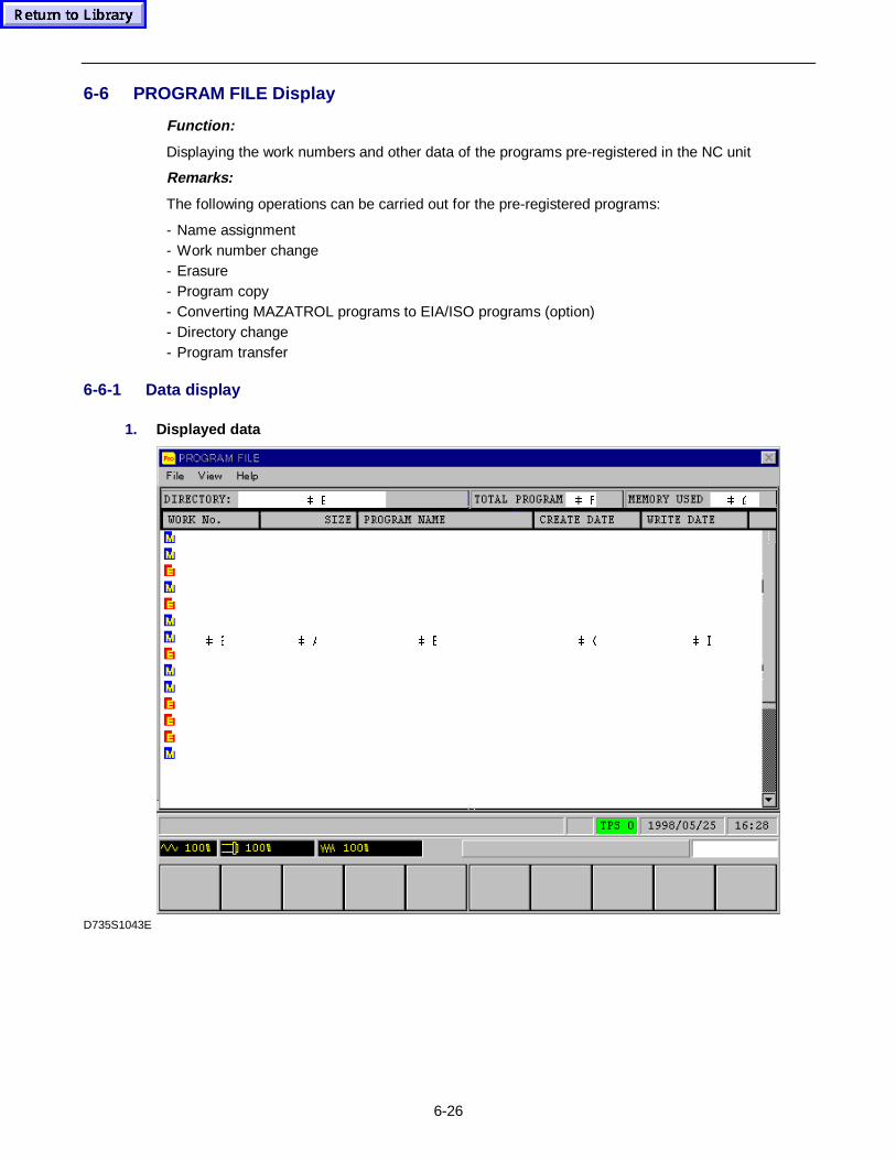
6-26
6-6 PROGRAM FILE Display
Function:
Displaying the work numbers and other data of the programs pre-registered in the NC unit
Remarks:
The following operations can be carried out for the pre-registered programs:
- Name assignment- Work number change- Erasure- Program copy- Converting MAZATROL programs to EIA/ISO programs (option)- Directory change- Program transfer
6-6-1 Data display
1. Displayed data
 * ) (
 ' & % $ #
D735S1043E
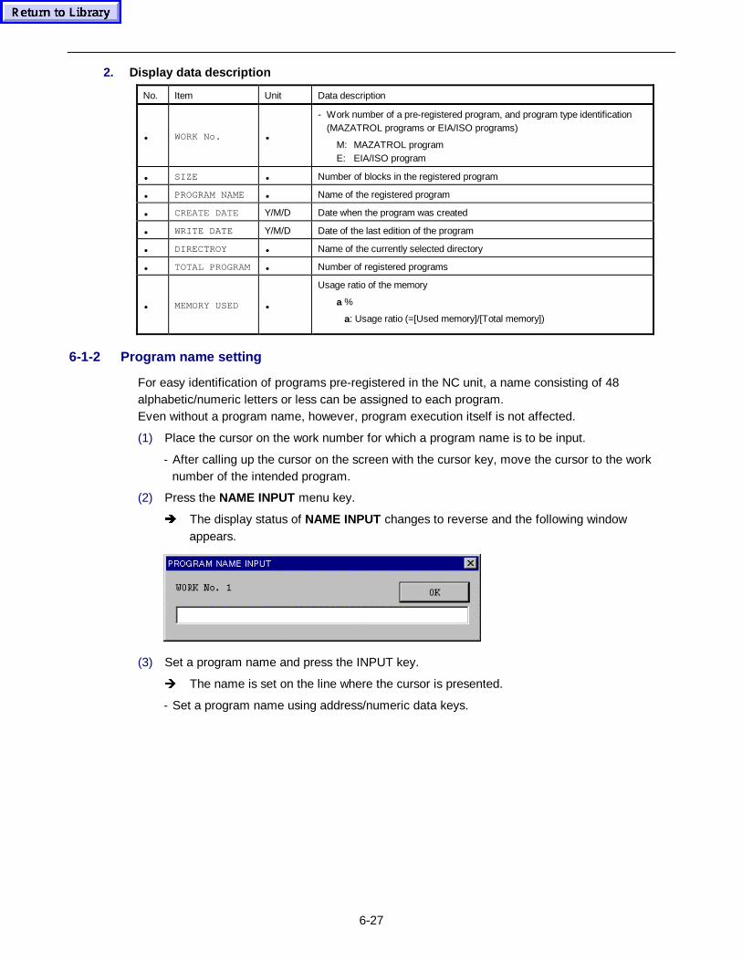
6-27
2. Display data description
No. Item Unit Data description
• WORK No. •
- Work number of a pre-registered program, and program type identification(MAZATROL programs or EIA/ISO programs)
M: MAZATROL programE: EIA/ISO program
• SIZE • Number of blocks in the registered program
• PROGRAM NAME • Name of the registered program
• CREATE DATE Y/M/D Date when the program was created
• WRITE DATE Y/M/D Date of the last edition of the program
• DIRECTROY • Name of the currently selected directory
• TOTAL PROGRAM • Number of registered programs
• MEMORY USED •
Usage ratio of the memory
a %
a: Usage ratio (=[Used memory]/[Total memory])
6-1-2 Program name setting
For easy identification of programs pre-registered in the NC unit, a name consisting of 48alphabetic/numeric letters or less can be assigned to each program.Even without a program name, however, program execution itself is not affected.
(1) Place the cursor on the work number for which a program name is to be input.
- After calling up the cursor on the screen with the cursor key, move the cursor to the worknumber of the intended program.
(2) Press the NAME INPUT menu key.
Î The display status of NAME INPUT changes to reverse and the following windowappears.
(3) Set a program name and press the INPUT key.
Î The name is set on the line where the cursor is presented.
- Set a program name using address/numeric data keys.
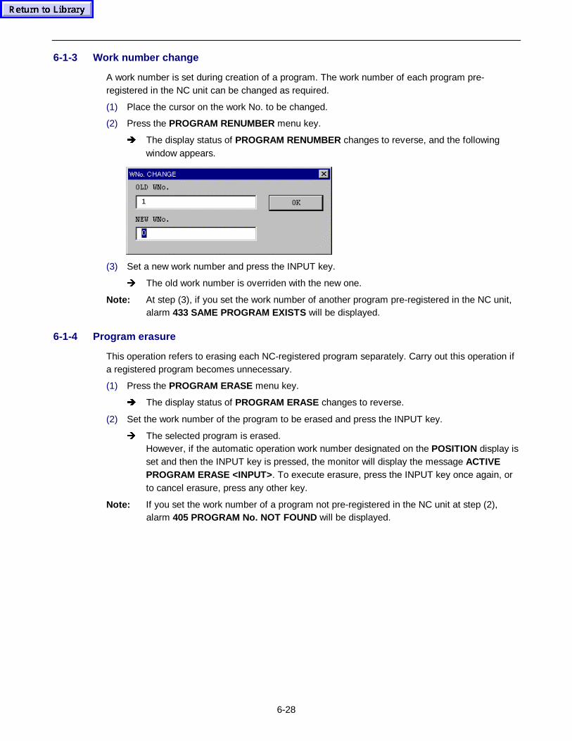
6-28
6-1-3 Work number change
A work number is set during creation of a program. The work number of each program pre-registered in the NC unit can be changed as required.
(1) Place the cursor on the work No. to be changed.
(2) Press the PROGRAM RENUMBER menu key.
Î The display status of PROGRAM RENUMBER changes to reverse, and the followingwindow appears.
(3) Set a new work number and press the INPUT key.
Î The old work number is overriden with the new one.
Note: At step (3), if you set the work number of another program pre-registered in the NC unit,alarm 433 SAME PROGRAM EXISTS will be displayed.
6-1-4 Program erasure
This operation refers to erasing each NC-registered program separately. Carry out this operation ifa registered program becomes unnecessary.
(1) Press the PROGRAM ERASE menu key.
Î The display status of PROGRAM ERASE changes to reverse.
(2) Set the work number of the program to be erased and press the INPUT key.
Î The selected program is erased.However, if the automatic operation work number designated on the POSITION display isset and then the INPUT key is pressed, the monitor will display the message ACTIVEPROGRAM ERASE <INPUT> . To execute erasure, press the INPUT key once again, orto cancel erasure, press any other key.
Note: If you set the work number of a program not pre-registered in the NC unit at step (2),alarm 405 PROGRAM No. NOT FOUND will be displayed.
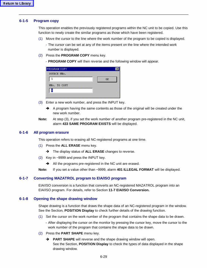
6-29
6-1-5 Program copy
This operation enables the previously registered programs within the NC unit to be copied. Use thisfunction to newly create the similar programs as those which have been registered.
(1) Move the cursor to the line where the work number of the program to be copied is displayed.
- The cursor can be set at any of the items present on the line where the intended worknumber is displayed.
(2) Press the PROGRAM COPY menu key.
- PROGRAM COPY will then reverse and the following window will appear.
(3) Enter a new work number, and press the INPUT key.
Î A program having the same contents as those of the original will be created under thenew work number.
Note: At step (3), if you set the work number of another program pre-registered in the NC unit,alarm 433 SAME PROGRAM EXISTS will be displayed.
6-1-6 All program erasure
This operation refers to erasing all NC-registered programs at one time.
(1) Press the ALL ERASE menu key.
Î The display status of ALL ERASE changes to reverse.
(2) Key in −9999 and press the INPUT key.
Î All the programs pre-registered in the NC unit are erased.
Note: If you set a value other than −9999, alarm 401 ILLEGAL FORMAT will be displayed.
6-1-7 Converting MAZATROL program to EIA/ISO program
EIA/ISO conversion is a function that converts an NC-registered MAZATROL program into anEIA/ISO program. For details, refer to Section 11-7 EIA/ISO Convers ion.
6-1-8 Opening the shape drawing window
Shape drawing is a function that draws the shape data of an NC-registered program in the window.See the Section, POSITION Display to check further details of the drawing function.
(1) Set the cursor on the work number of the program that contains the shape data to be drawn.
- After displaying the cursor on the monitor by pressing the cursor key, move the cursor to thework number of the program that contains the shape data to be drawn.
(2) Press the PART SHAPE menu key.
Î PART SHAPE will reverse and the shape drawing window will open.See the Section, POSITION Display to check the types of data displayed in the shapedrawing window.
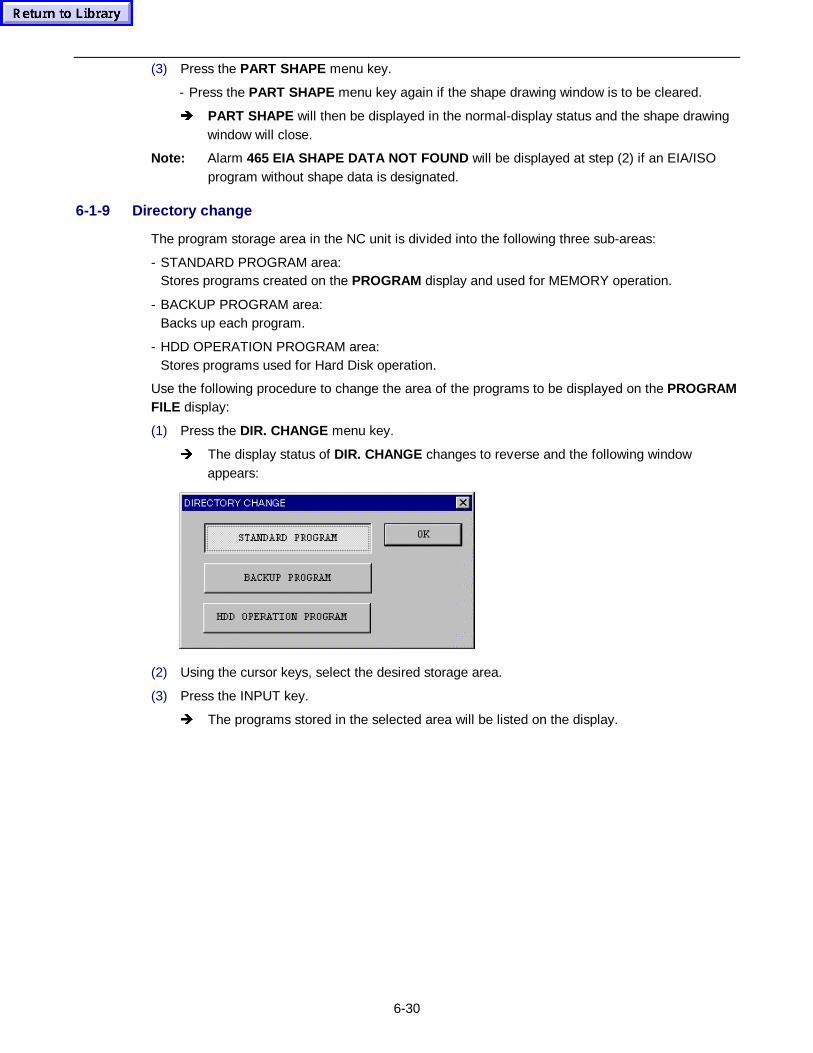
6-30
(3) Press the PART SHAPE menu key.
- Press the PART SHAPE menu key again if the shape drawing window is to be cleared.
Î PART SHAPE will then be displayed in the normal-display status and the shape drawingwindow will close.
Note: Alarm 465 EIA SHAPE DATA NOT FOUND will be displayed at step (2) if an EIA/ISOprogram without shape data is designated.
6-1-9 Directory change
The program storage area in the NC unit is divided into the following three sub-areas:
- STANDARD PROGRAM area:Stores programs created on the PROGRAM display and used for MEMORY operation.
- BACKUP PROGRAM area:Backs up each program.
- HDD OPERATION PROGRAM area:Stores programs used for Hard Disk operation.
Use the following procedure to change the area of the programs to be displayed on the PROGRAMFILE display:
(1) Press the DIR. CHANGE menu key.
Î The display status of DIR. CHANGE changes to reverse and the following windowappears:
(2) Using the cursor keys, select the desired storage area.
(3) Press the INPUT key.
Î The programs stored in the selected area will be listed on the display.
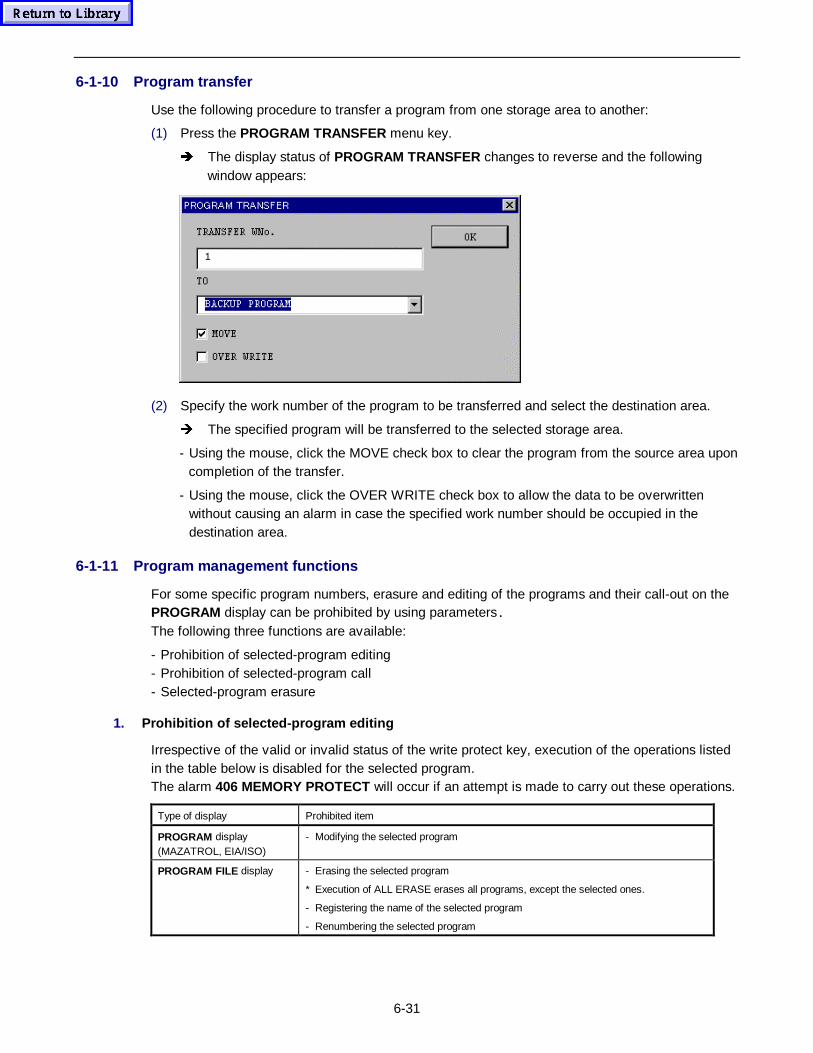
6-31
6-1-10 Program transfer
Use the following procedure to transfer a program from one storage area to another:
(1) Press the PROGRAM TRANSFER menu key.
Î The display status of PROGRAM TRANSFER changes to reverse and the followingwindow appears:
(2) Specify the work number of the program to be transferred and select the destination area.
Î The specified program will be transferred to the selected storage area.
- Using the mouse, click the MOVE check box to clear the program from the source area uponcompletion of the transfer.
- Using the mouse, click the OVER WRITE check box to allow the data to be overwrittenwithout causing an alarm in case the specified work number should be occupied in thedestination area.
6-1-11 Program management functions
For some specific program numbers, erasure and editing of the programs and their call-out on thePROGRAM display can be prohibited by using parameters.
The following three functions are available:
- Prohibition of selected-program editing- Prohibition of selected-program call- Selected-program erasure
1. Prohibition of selected-prog ram editing
Irrespective of the valid or invalid status of the write protect key, execution of the operations listedin the table below is disabled for the selected program.The alarm 406 MEMORY PROTECT will occur if an attempt is made to carry out these operations.
Type of display Prohibited item
PROGRAM display(MAZATROL, EIA/ISO)
- Modifying the selected program
PROGRAM FILE display - Erasing the selected program
* Execution of ALL ERASE erases all programs, except the selected ones.
- Registering the name of the selected program
- Renumbering the selected program
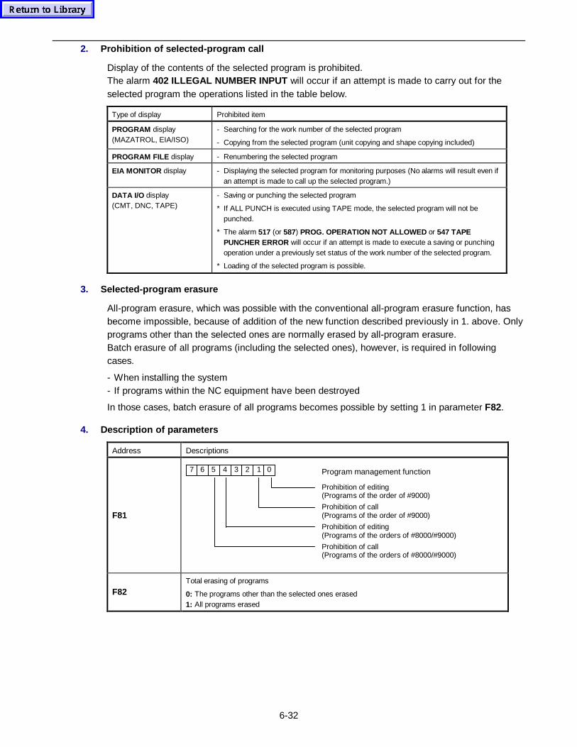
6-32
2. Prohibition of selected-prog ram call
Display of the contents of the selected program is prohibited.The alarm 402 ILLEGAL NUMBER INPUT will occur if an attempt is made to carry out for theselected program the operations listed in the table below.
Type of display Prohibited item
PROGRAM display(MAZATROL, EIA/ISO)
- Searching for the work number of the selected program
- Copying from the selected program (unit copying and shape copying included)
PROGRAM FILE display - Renumbering the selected program
EIA MONITOR display - Displaying the selected program for monitoring purposes (No alarms will result even ifan attempt is made to call up the selected program.)
DATA I/O display(CMT, DNC, TAPE)
- Saving or punching the selected program
* If ALL PUNCH is executed using TAPE mode, the selected program will not bepunched.
* The alarm 517 (or 587) PROG. OPERATION NOT ALLOWED or 547 TAPEPUNCHER ERROR will occur if an attempt is made to execute a saving or punchingoperation under a previously set status of the work number of the selected program.
* Loading of the selected program is possible.
3. Selected-program erasure
All-program erasure, which was possible with the conventional all-program erasure function, hasbecome impossible, because of addition of the new function described previously in 1. above. Onlyprograms other than the selected ones are normally erased by all-program erasure.Batch erasure of all programs (including the selected ones), however, is required in followingcases.
- When installing the system- If programs within the NC equipment have been destroyed
In those cases, batch erasure of all programs becomes possible by setting 1 in parameter F82.
4. Descript ion of p arameters
Address Descriptions
F81
7 6 5 3 2 1 04 Program management function
Prohibition of editing(Programs of the order of #9000)
Prohibition of call(Programs of the order of #9000)
Prohibition of editing(Programs of the orders of #8000/#9000)
Prohibition of call(Programs of the orders of #8000/#9000)
F82Total erasing of programs
0: The programs other than the selected ones erased1: All programs erased
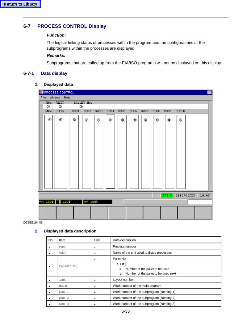
6-33
6-7 PROCESS CONTROL Display
Function:
The logical linking status of processes within the program and the configurations of thesubprograms within the processes are displayed.
Remarks:
Subprograms that are called up from the EIA/ISO programs will not be displayed on this display.
6-7-1 Data display
1. Displayed data
D735S1044E
2. Displayed data description
No. Item Unit Data description
• PNo. • Process number
• UNIT • Name of the unit used to divide processes
• PALLET No.
• Pallet No.
a ( b )
a: Number of the pallet to be usedb: Number of the pallet to be used next
• LNo. • Layout number
• MAIN • Work number of the main program
• SUB 1 • Work number of the subprogram (Nesting 1)
• SUB 2 • Work number of the subprogram (Nesting 2)
• SUB 3 • Work number of the subprogram (Nesting 3)
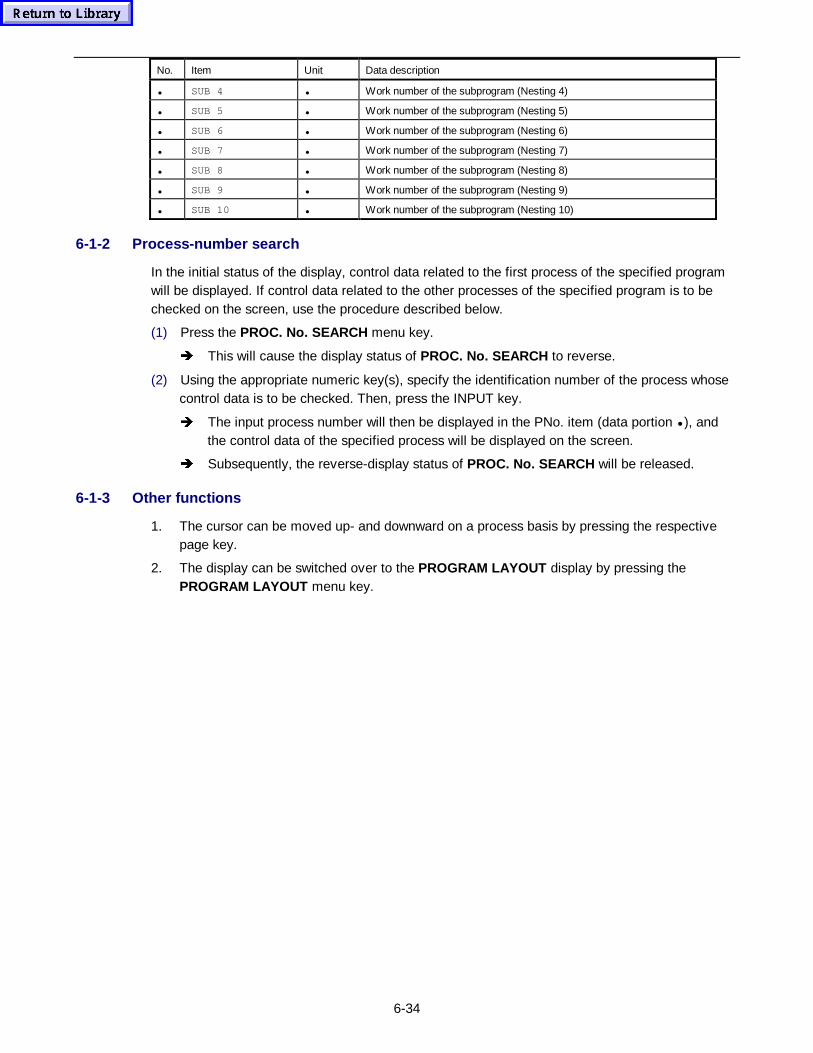
6-34
No. Item Unit Data description
• SUB 4 • Work number of the subprogram (Nesting 4)
• SUB 5 • Work number of the subprogram (Nesting 5)
• SUB 6 • Work number of the subprogram (Nesting 6)
• SUB 7 • Work number of the subprogram (Nesting 7)
• SUB 8 • Work number of the subprogram (Nesting 8)
• SUB 9 • Work number of the subprogram (Nesting 9)
• SUB 10 • Work number of the subprogram (Nesting 10)
6-1-2 Process-number search
In the initial status of the display, control data related to the first process of the specified programwill be displayed. If control data related to the other processes of the specified program is to bechecked on the screen, use the procedure described below.
(1) Press the PROC. No. SEARCH menu key.
Î This will cause the display status of PROC. No. SEARCH to reverse.
(2) Using the appropriate numeric key(s), specify the identification number of the process whosecontrol data is to be checked. Then, press the INPUT key.
Î The input process number will then be displayed in the PNo. item (data portion • ), andthe control data of the specified process will be displayed on the screen.
Î Subsequently, the reverse-display status of PROC. No. SEARCH will be released.
6-1-3 Other functions
1. The cursor can be moved up- and downward on a process basis by pressing the respectivepage key.
2. The display can be switched over to the PROGRAM LAYOUT display by pressing thePROGRAM LAYOUT menu key.

6-35
6-8 PROGRAM LAYOUT Display
Function:
- The tools to be used in the processes of the MAZATROL program are displayed in the order ofmachining.
- This display can be used to edit a tool priority number and to write the data into the program.
Remarks:
- For both multi-workpiece machining and subprogram looping, only one time of program data isdisplayed.
- This display can be called up from the PROGRAM (MAZATROL) display, the PROCESSCONTROL display and the DISPLAY MAP display. When this display is called from thePROGRAM or PROCESS CONTROL display, process layout information for the cursor positionis displayed. When the PROGRAM LAYOUT display is called from the DISPLAY MAP display,the process layout information is displayed from the head of the program.
6-8-1 Data display
1. Displayed data
D735S1045E
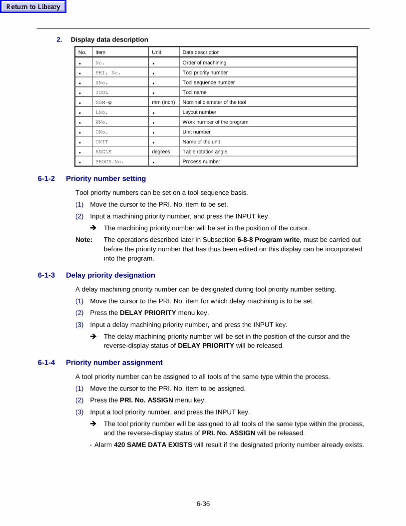
6-36
2. Display data description
No. Item Unit Data description
• No. • Order of machining
• PRI. No. • Tool priority number
• SNo. • Tool sequence number
• TOOL • Tool name
• NOM-φ mm (inch) Nominal diameter of the tool
• LNo. • Layout number
• WNo. • Work number of the program
• UNo. • Unit number
• UNIT • Name of the unit
• ANGLE degrees Table rotation angle
• PROCE.No. • Process number
6-1-2 Priority number setting
Tool priority numbers can be set on a tool sequence basis.
(1) Move the cursor to the PRI. No. item to be set.
(2) Input a machining priority number, and press the INPUT key.
Î The machining priority number will be set in the position of the cursor.
Note: The operations described later in Subsection 6-8-8 Program write , must be carried outbefore the priority number that has thus been edited on this display can be incorporatedinto the program.
6-1-3 Delay priority designation
A delay machining priority number can be designated during tool priority number setting.
(1) Move the cursor to the PRI. No. item for which delay machining is to be set.
(2) Press the DELAY PRIORITY menu key.
(3) Input a delay machining priority number, and press the INPUT key.
Î The delay machining priority number will be set in the position of the cursor and thereverse-display status of DELAY PRIORITY will be released.
6-1-4 Priority number assignment
A tool priority number can be assigned to all tools of the same type within the process.
(1) Move the cursor to the PRI. No. item to be assigned.
(2) Press the PRI. No. ASSIGN menu key.
(3) Input a tool priority number, and press the INPUT key.
Î The tool priority number will be assigned to all tools of the same type within the process,and the reverse-display status of PRI. No. ASSIGN will be released.
- Alarm 420 SAME DATA EXISTS will result if the designated priority number already exists.
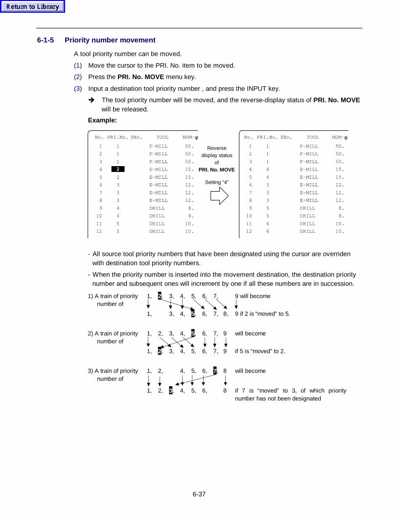
6-37
6-1-5 Priority number movement
A tool priority number can be moved.
(1) Move the cursor to the PRI. No. item to be moved.
(2) Press the PRI. No. MOVE menu key.
(3) Input a destination tool priority number , and press the INPUT key.
Î The tool priority number will be moved, and the reverse-display status of PRI. No. MOVEwill be released.
Example:
No. PRI.No. SNo. TOOL NOM- φ No. PRI.No. SNo. TOOL NOM- φ
1 1 F-MILL 50. 1 1 F-MILL 50.
2 1 F-MILL 50. 2 1 F-MILL 50.
3 1 F-MILL 50. 3 1 F-MILL 50.
4 2 E-MILL 15. 4 4 E-MILL 15.
5 2 E-MILL 15. 5 4 E-MILL 15.
6 3 E-MILL 12. 6 3 E-MILL 12.
7 3 E-MILL 12. 7 3 E-MILL 12.
8 3 E-MILL 12. 8 3 E-MILL 12.
9 4 DRILL 8. 9 5 DRILL 8.
10 4 DRILL 8. 10 5 DRILL 8.
11 5 DRILL 10. 11 6 DRILL 10.
12 5 DRILL 10.
Reversedisplay status
ofPRI. No. MOVE
Setting “4”
12 6 DRILL 10.
- All source tool priority numbers that have been designated using the cursor are overridenwith destination tool priority numbers.
- When the priority number is inserted into the movement destination, the destination prioritynumber and subsequent ones will increment by one if all these numbers are in succession.
1) A train of prioritynumber of
1, 2, 3, 4, 5, 6, 7, 9 will become
1, 3, 4, 5, 6, 7, 8, 9 if 2 is “moved” to 5.
2) A train of prioritynumber of
1, 2, 3, 4, 5, 6, 7, 9 will become
1, 2, 3, 4, 5, 6, 7, 9 if 5 is “moved” to 2.
3) A train of prioritynumber of
1, 2, 4, 5, 6, 7, 8 will become
1, 2, 3, 4, 5, 6, 8 if 7 is “moved” to 3, of which prioritynumber has not been designated
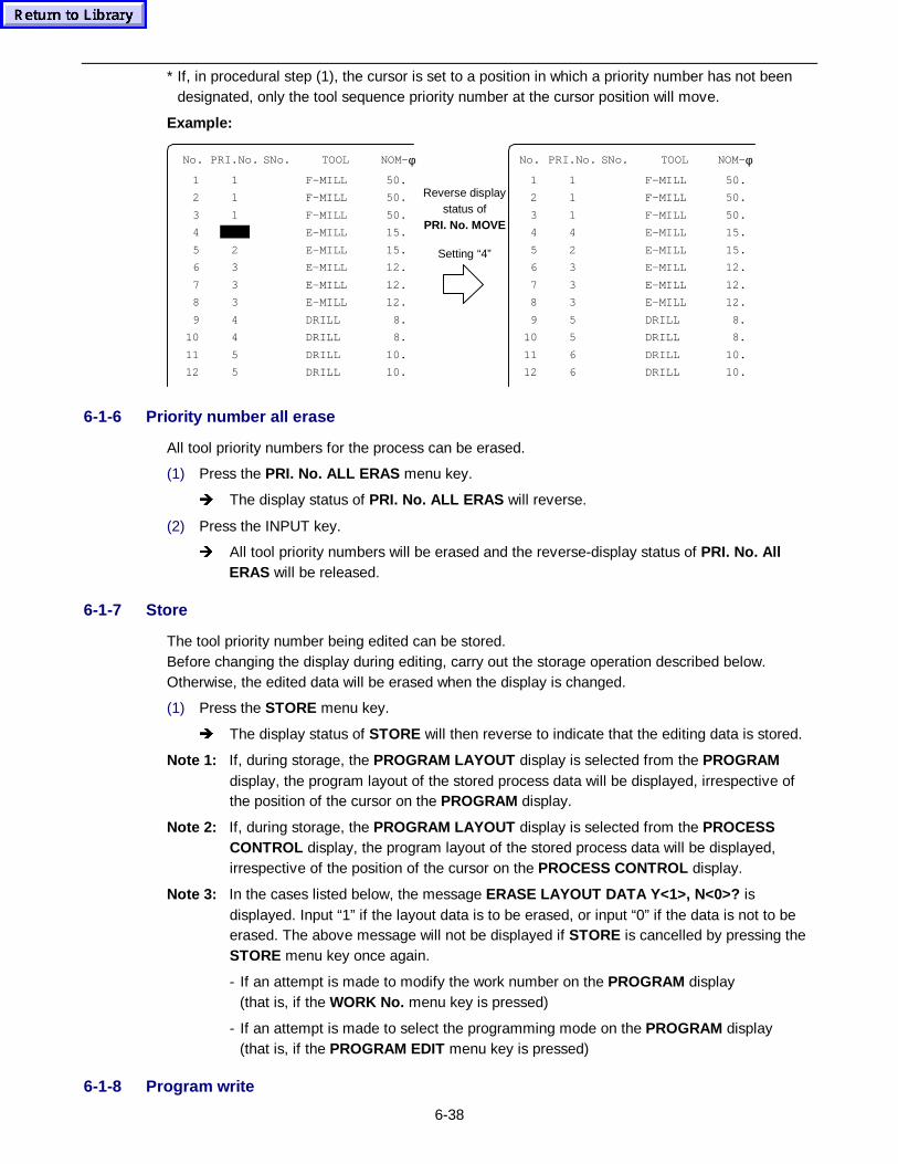
6-38
* If, in procedural step (1), the cursor is set to a position in which a priority number has not beendesignated, only the tool sequence priority number at the cursor position will move.
Example:
No. PRI.No. SNo. TOOL NOM- φ No. PRI.No. SNo. TOOL NOM- φ
1 1 F-MILL 50. 1 1 F-MILL 50.
2 1 F-MILL 50. 2 1 F-MILL 50.
3 1 F-MILL 50. 3 1 F-MILL 50.
4 E-MILL 15. 4 4 E-MILL 15.
5 2 E-MILL 15. 5 2 E-MILL 15.
6 3 E-MILL 12. 6 3 E-MILL 12.
7 3 E-MILL 12. 7 3 E-MILL 12.
8 3 E-MILL 12. 8 3 E-MILL 12.
9 4 DRILL 8. 9 5 DRILL 8.
10 4 DRILL 8. 10 5 DRILL 8.
11 5 DRILL 10. 11 6 DRILL 10.
12 5 DRILL 10.
Reverse displaystatus of
PRI. No. MOVE
Setting “4”
12 6 DRILL 10.
6-1-6 Priority number all erase
All tool priority numbers for the process can be erased.
(1) Press the PRI. No. ALL ERAS menu key.
Î The display status of PRI. No. ALL ERAS will reverse.
(2) Press the INPUT key.
Î All tool priority numbers will be erased and the reverse-display status of PRI. No. AllERAS will be released.
6-1-7 Store
The tool priority number being edited can be stored.Before changing the display during editing, carry out the storage operation described below.Otherwise, the edited data will be erased when the display is changed.
(1) Press the STORE menu key.
Î The display status of STORE will then reverse to indicate that the editing data is stored.
Note 1: If, during storage, the PROGRAM LAYOUT display is selected from the PROGRAMdisplay, the program layout of the stored process data will be displayed, irrespective ofthe position of the cursor on the PROGRAM display.
Note 2: If, during storage, the PROGRAM LAYOUT display is selected from the PROCESSCONTROL display, the program layout of the stored process data will be displayed,irrespective of the position of the cursor on the PROCESS CONTROL display.
Note 3: In the cases listed below, the message ERASE LAYOUT DATA Y<1>, N<0>? isdisplayed. Input “1” if the layout data is to be erased, or input “0” if the data is not to beerased. The above message will not be displayed if STORE is cancelled by pressing theSTORE menu key once again.
- If an attempt is made to modify the work number on the PROGRAM display(that is, if the WORK No. menu key is pressed)
- If an attempt is made to select the programming mode on the PROGRAM display(that is, if the PROGRAM EDIT menu key is pressed)
6-1-8 Program write
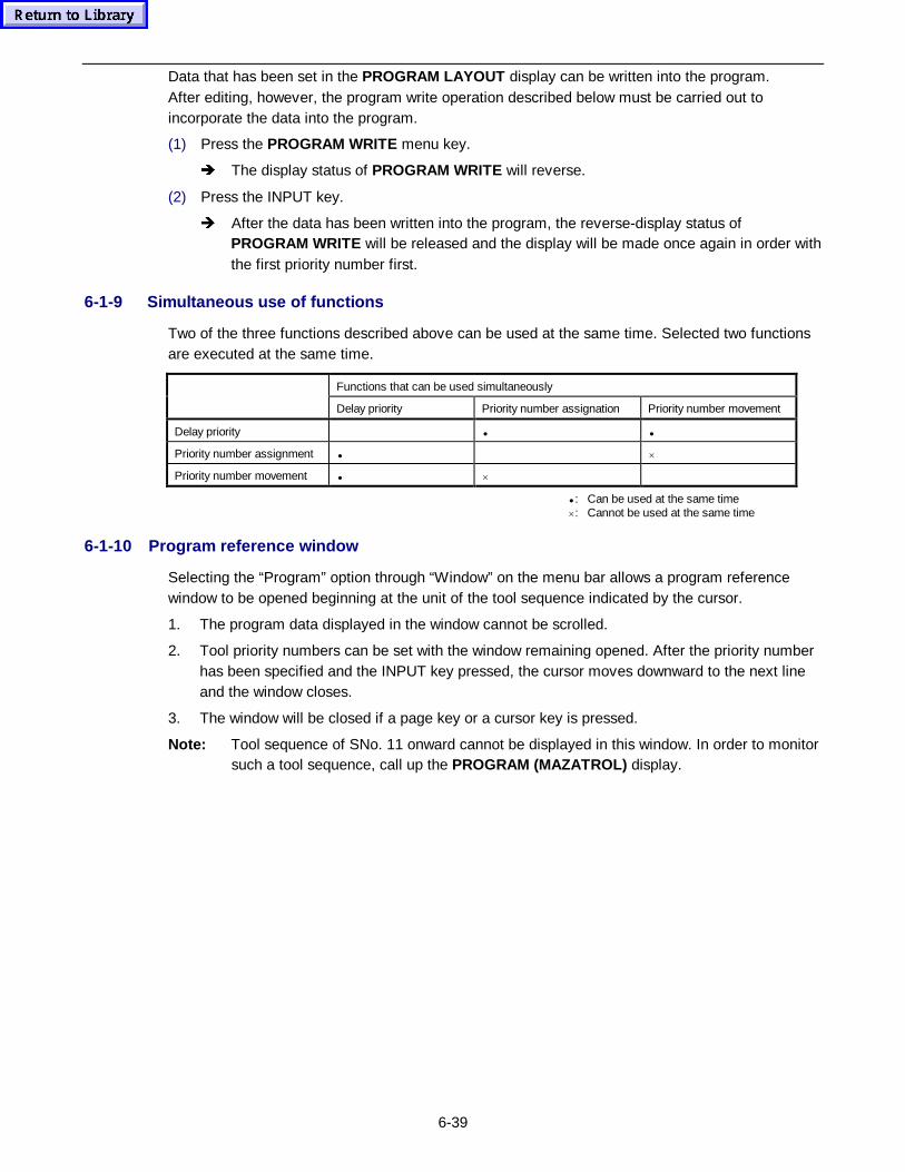
6-39
Data that has been set in the PROGRAM LAYOUT display can be written into the program.After editing, however, the program write operation described below must be carried out toincorporate the data into the program.
(1) Press the PROGRAM WRITE menu key.
Î The display status of PROGRAM WRITE will reverse.
(2) Press the INPUT key.
Î After the data has been written into the program, the reverse-display status ofPROGRAM WRITE will be released and the display will be made once again in order withthe first priority number first.
6-1-9 Simultaneous use of functions
Two of the three functions described above can be used at the same time. Selected two functionsare executed at the same time.
Functions that can be used simultaneously
Delay priority Priority number assignation Priority number movement
Delay priority • •
Priority number assignment • ×
Priority number movement • ×
• : Can be used at the same time×: Cannot be used at the same time
6-1-10 Program reference window
Selecting the “Program” option through “Window” on the menu bar allows a program referencewindow to be opened beginning at the unit of the tool sequence indicated by the cursor.
1. The program data displayed in the window cannot be scrolled.
2. Tool priority numbers can be set with the window remaining opened. After the priority numberhas been specified and the INPUT key pressed, the cursor moves downward to the next lineand the window closes.
3. The window will be closed if a page key or a cursor key is pressed.
Note: Tool sequence of SNo. 11 onward cannot be displayed in this window. In order to monitorsuch a tool sequence, call up the PROGRAM (MAZATROL) display.
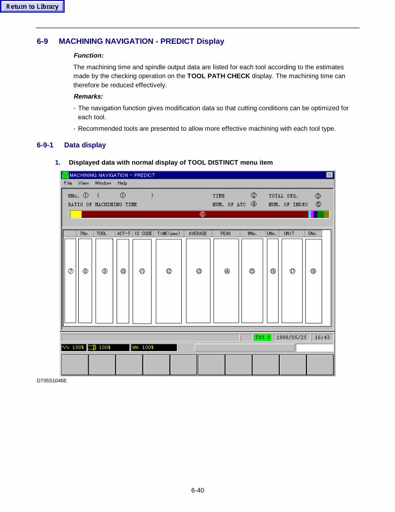
6-40
6-9 MACHINING NAVIGATION - PREDICT Display
Function:
The machining time and spindle output data are listed for each tool according to the estimatesmade by the checking operation on the TOOL PATH CHECK display. The machining time cantherefore be reduced effectively.
Remarks:
- The navigation function gives modification data so that cutting conditions can be optimized foreach tool.
- Recommended tools are presented to allow more effective machining with each tool type.
6-9-1 Data display
1. Displayed data with normal display of T OOL DISTINCT menu item
D735S1046E
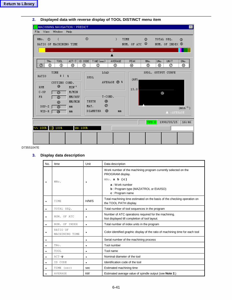
6-41
2. Displayed data with reverse display of T OOL DISTINCT menu item
 5
D735S1047E
3. Display data description
No. Itme Unit Data description
• WNo. •
Work number of the machining program currently selected on thePROGRAM display.
WNo. a b ( c )
a : Work numberb : Program type (MAZATROL or EIA/ISO)c : Program name
• TIME H/M/STotal machining time estimated on the basis of the checking operation onthe TOOL PATH display.
• TOTAL SEQ. • Total number of tool sequences in the program
• NUM. OF ATC •Number of ATC operations required for the machining.Not displayed till completion of tool layout.
• NUM. OF INDEX • Total number of index units in the program
•RATIO OF
MACHINING TIME• Color-identified graphic display of the ratio of machining time for each tool
• • Serial number of the machining process
• TNo. • Tool number
• TOOL • Tool name
• ACT-φ • Nominal diameter of the tool
• ID CODE • Identification code of the tool
• TIME (sec) sec Estimated machining time
• AVERAGE kW Estimated average value of spindle output (see Note 2. )
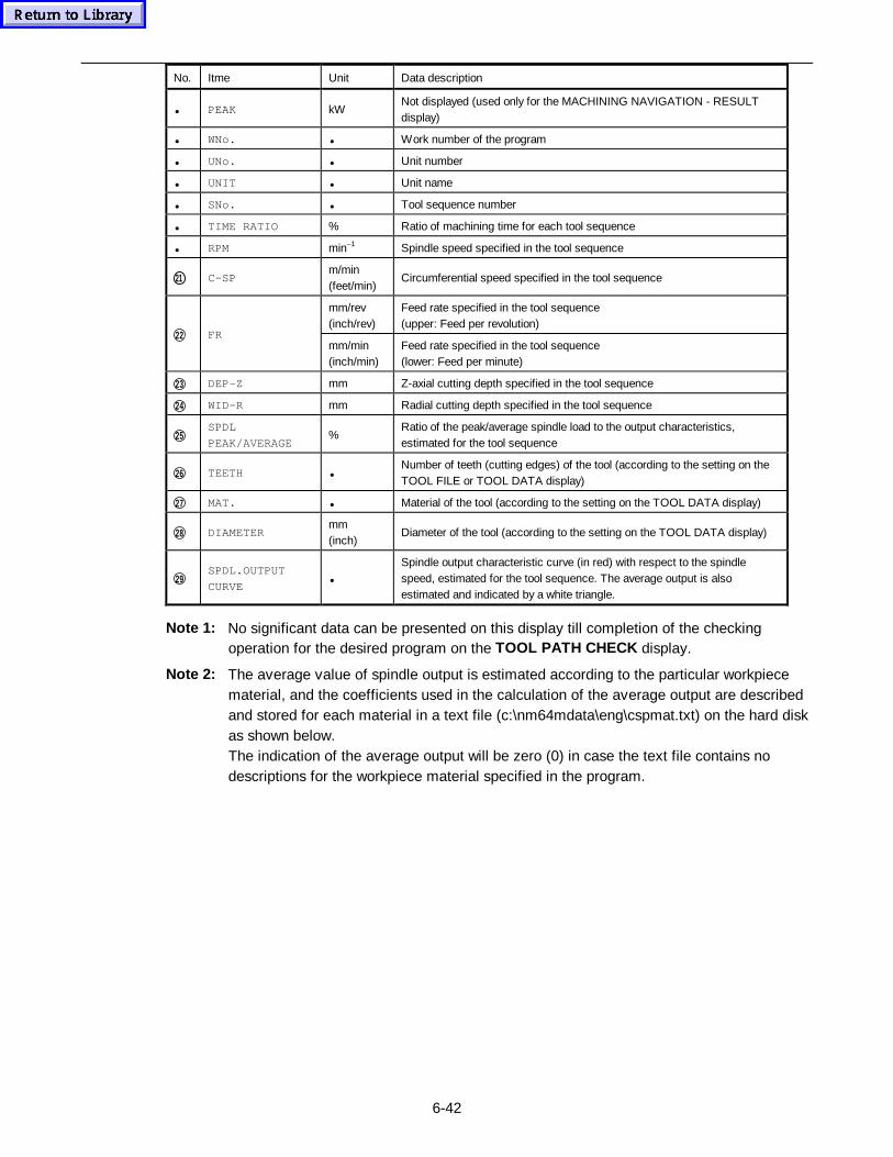
6-42
No. Itme Unit Data description
• PEAK kWNot displayed (used only for the MACHINING NAVIGATION - RESULTdisplay)
• WNo. • Work number of the program
• UNo. • Unit number
• UNIT • Unit name
• SNo. • Tool sequence number
• TIME RATIO % Ratio of machining time for each tool sequence
• RPM min–1 Spindle speed specified in the tool sequence
21 C-SPm/min(feet/min)
Circumferential speed specified in the tool sequence
mm/rev(inch/rev)
Feed rate specified in the tool sequence(upper: Feed per revolution)
22 FRmm/min(inch/min)
Feed rate specified in the tool sequence(lower: Feed per minute)
23 DEP-Z mm Z-axial cutting depth specified in the tool sequence
24 WID-R mm Radial cutting depth specified in the tool sequence
25SPDL
PEAK/AVERAGE%
Ratio of the peak/average spindle load to the output characteristics,estimated for the tool sequence
26 TEETH •Number of teeth (cutting edges) of the tool (according to the setting on theTOOL FILE or TOOL DATA display)
27 MAT. • Material of the tool (according to the setting on the TOOL DATA display)
28 DIAMETERmm(inch)
Diameter of the tool (according to the setting on the TOOL DATA display)
29SPDL.OUTPUT
CURVE•
Spindle output characteristic curve (in red) with respect to the spindlespeed, estimated for the tool sequence. The average output is alsoestimated and indicated by a white triangle.
Note 1: No significant data can be presented on this display till completion of the checkingoperation for the desired program on the TOOL PATH CHECK display.
Note 2: The average value of spindle output is estimated according to the particular workpiecematerial, and the coefficients used in the calculation of the average output are describedand stored for each material in a text file (c:\nm64mdata\eng\cspmat.txt) on the hard diskas shown below.The indication of the average output will be zero (0) in case the text file contains nodescriptions for the workpiece material specified in the program.
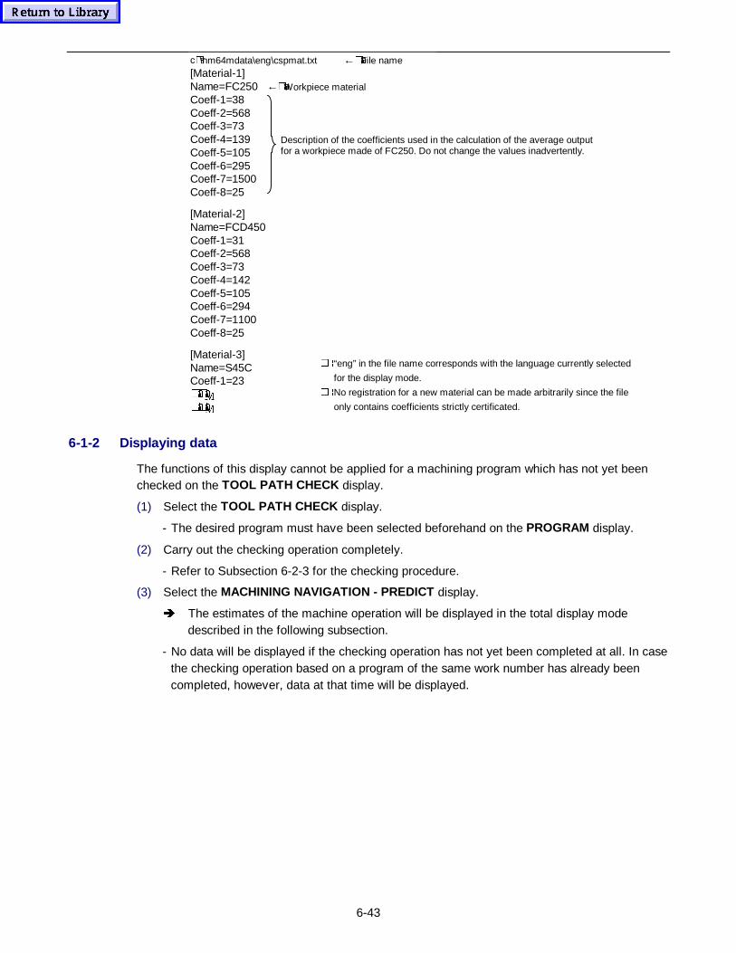
6-43
c�)\nm64mdata\eng\cspmat.txt ←�#File name[Material-1]Name=FC250 ←�#Workpiece materialCoeff-1=38Coeff-2=568Coeff-3=73Coeff-4=139Coeff-5=105Coeff-6=295Coeff-7=1500Coeff-8=25
[Material-2]Name=FCD450Coeff-1=31Coeff-2=568Coeff-3=73Coeff-4=142Coeff-5=105Coeff-6=294Coeff-7=1100Coeff-8=25
[Material-3]Name=S45CCoeff-1=23�#�#0
�#�#0
�è“eng” in the file name corresponds with the language currently selected
for the display mode.
�èNo registration for a new material can be made arbitrarily since the file
only contains coefficients strictly certificated.
Description of the coefficients used in the calculation of the average outputfor a workpiece made of FC250. Do not change the values inadvertently.
6-1-2 Displaying data
The functions of this display cannot be applied for a machining program which has not yet beenchecked on the TOOL PATH CHECK display.
(1) Select the TOOL PATH CHECK display.
- The desired program must have been selected beforehand on the PROGRAM display.
(2) Carry out the checking operation completely.
- Refer to Subsection 6-2-3 for the checking procedure.
(3) Select the MACHINING NAVIGATION - PREDICT display.
Î The estimates of the machine operation will be displayed in the total display modedescribed in the following subsection.
- No data will be displayed if the checking operation has not yet been completed at all. In casethe checking operation based on a program of the same work number has already beencompleted, however, data at that time will be displayed.
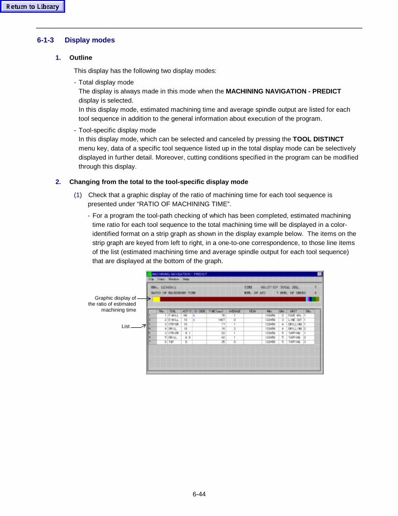
6-44
6-1-3 Display modes
1. Outline
This display has the following two display modes:
- Total display modeThe display is always made in this mode when the MACHINING NAVIGATION - PREDICTdisplay is selected.In this display mode, estimated machining time and average spindle output are listed for eachtool sequence in addition to the general information about execution of the program.
- Tool-specific display modeIn this display mode, which can be selected and canceled by pressing the TOOL DISTINCTmenu key, data of a specific tool sequence listed up in the total display mode can be selectivelydisplayed in further detail. Moreover, cutting conditions specified in the program can be modifiedthrough this display.
2. Changing from the total to the tool-specific display mode
(1) Check that a graphic display of the ratio of machining time for each tool sequence ispresented under “RATIO OF MACHINING TIME”.
- For a program the tool-path checking of which has been completed, estimated machiningtime ratio for each tool sequence to the total machining time will be displayed in a color-identified format on a strip graph as shown in the display example below. The items on thestrip graph are keyed from left to right, in a one-to-one correspondence, to those line itemsof the list (estimated machining time and average spindle output for each tool sequence)that are displayed at the bottom of the graph.
Graphic display ofthe ratio of estimated
machining time
List
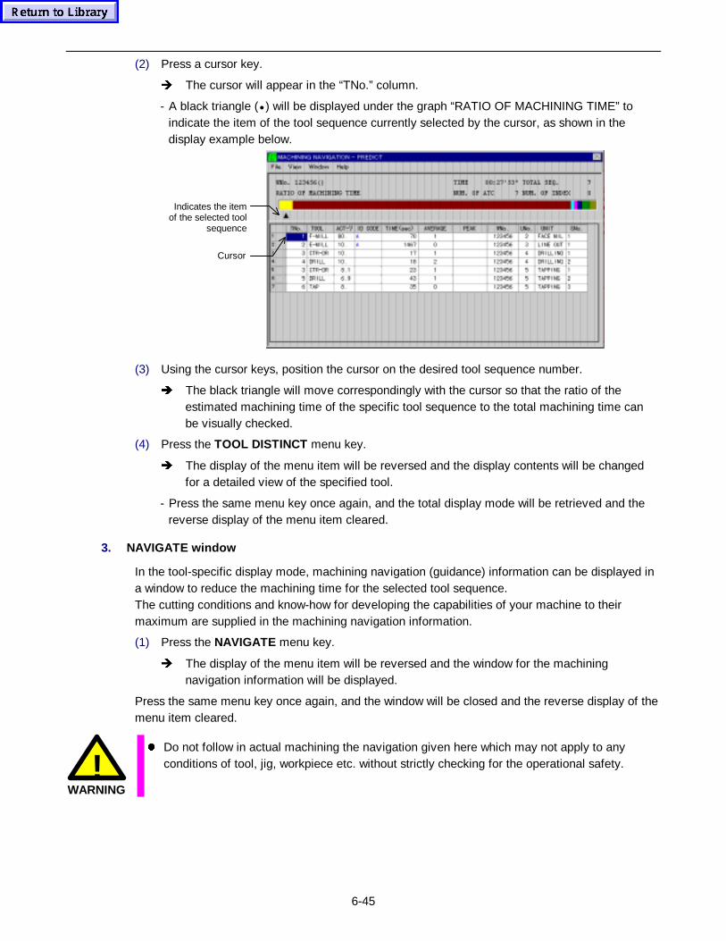
6-45
(2) Press a cursor key.
Î The cursor will appear in the “TNo.” column.
- A black triangle (• ) will be displayed under the graph “RATIO OF MACHINING TIME” toindicate the item of the tool sequence currently selected by the cursor, as shown in thedisplay example below.
Indicates the itemof the selected tool
sequence
Cursor
(3) Using the cursor keys, position the cursor on the desired tool sequence number.
Î The black triangle will move correspondingly with the cursor so that the ratio of theestimated machining time of the specific tool sequence to the total machining time canbe visually checked.
(4) Press the TOOL DISTINCT menu key.
Î The display of the menu item will be reversed and the display contents will be changedfor a detailed view of the specified tool.
- Press the same menu key once again, and the total display mode will be retrieved and thereverse display of the menu item cleared.
3. NAVIGATE window
In the tool-specific display mode, machining navigation (guidance) information can be displayed ina window to reduce the machining time for the selected tool sequence.The cutting conditions and know-how for developing the capabilities of your machine to theirmaximum are supplied in the machining navigation information.
(1) Press the NAVIGATE menu key.
Î The display of the menu item will be reversed and the window for the machiningnavigation information will be displayed.
Press the same menu key once again, and the window will be closed and the reverse display of themenu item cleared.
!WARNING
z Do not follow in actual machining the navigation given here which may not apply to anyconditions of tool, jig, workpiece etc. without strictly checking for the operational safety.
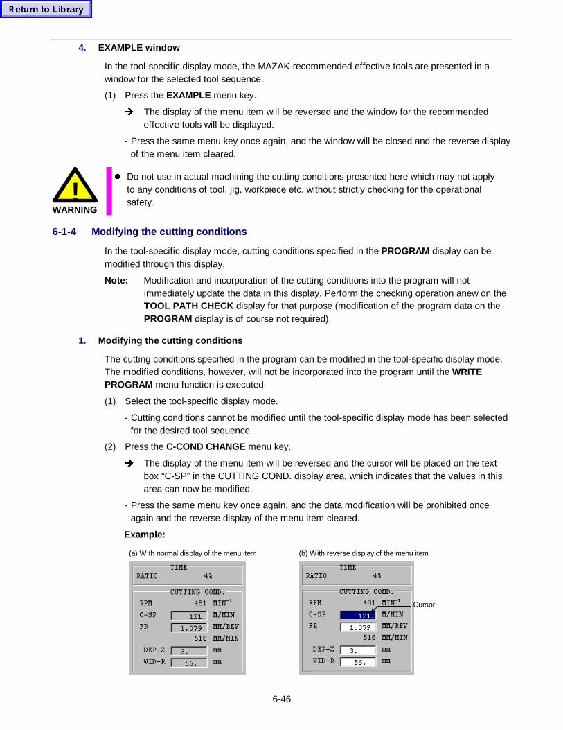
6-46
4. EXAMPLE window
In the tool-specific display mode, the MAZAK-recommended effective tools are presented in awindow for the selected tool sequence.
(1) Press the EXAMPLE menu key.
Î The display of the menu item will be reversed and the window for the recommendedeffective tools will be displayed.
- Press the same menu key once again, and the window will be closed and the reverse displayof the menu item cleared.
!WARNING
z Do not use in actual machining the cutting conditions presented here which may not applyto any conditions of tool, jig, workpiece etc. without strictly checking for the operationalsafety.
6-1-4 Modifying the cutting conditions
In the tool-specific display mode, cutting conditions specified in the PROGRAM display can bemodified through this display.
Note: Modification and incorporation of the cutting conditions into the program will notimmediately update the data in this display. Perform the checking operation anew on theTOOL PATH CHECK display for that purpose (modification of the program data on thePROGRAM display is of course not required).
1. Modifying the cutting conditions
The cutting conditions specified in the program can be modified in the tool-specific display mode.The modified conditions, however, will not be incorporated into the program until the WRITEPROGRAM menu function is executed.
(1) Select the tool-specific display mode.
- Cutting conditions cannot be modified until the tool-specific display mode has been selectedfor the desired tool sequence.
(2) Press the C-COND CHANGE menu key.
Î The display of the menu item will be reversed and the cursor will be placed on the textbox “C-SP” in the CUTTING COND. display area, which indicates that the values in thisarea can now be modified.
- Press the same menu key once again, and the data modification will be prohibited onceagain and the reverse display of the menu item cleared.
Example:
(a) With normal display of the menu item (b) With reverse display of the menu item
Cursor
6-47
Note: It is possible to edit the four cutting conditions displayed in the CUTTING COND.display area (C-SP, FR, DEP-Z and WID-R), of which, however, only thosecorresponding to the selected tool sequence are subjected to the edition.Refer to the Programming Manual - MAZATROL - for the description of the dataitems of the tool sequence.
(3) Using the cursor keys, position the cursor on the desired text box.
- The cursor can only be placed on the available boxes.
(4) Specify new cutting condition and press the INPUT key.
Î The value selected by the cursor will be overridden by the new data.
2. Cancelling the modification
Before execution of the WRITE PROGRAM menu function, the modification data can any time becanceled and the original data retrieved by the following procedure:
(1) Press the CLEAR DATA menu key.
Î The entire text data in the CUTTING COND. display area will be changed to the originaldata (current settings on the PROGRAM display).
- This operation can be performed any time, irrespective of the display status of the C-CONDCHANGE menu item, unless the WRITE PROGRAM menu function has been executed.
3. Incorporating the modification into the program
Carry out the following operation to incorporate the modified cutting conditions into the program:
(1) Press the WRITE PROGRAM menu key.
(2) Press the INPUT key.
Î The modified cutting conditions will be incorporated definitely into the program.
- This operation can be performed any time, irrespective of the display status of the C-CONDCHANGE menu item.
Note: Once this menu item has been selected, the modification clearing operation described initem 2 above will only retrieve the modified values (the original data will have beencleared from the memory).

6-48
- NOTE -
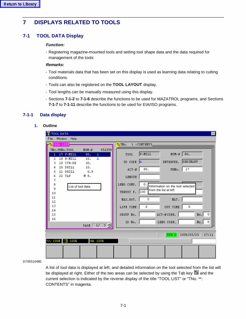
7-1
7 DISPLAYS RELATED TO TOOLS
7-1 TOOL DATA Display
Function:
- Registering magazine-mounted tools and setting tool shape data and the data required formanagement of the tools
Remarks:
- Tool materials data that has been set on this display is used as learning data relating to cuttingconditions.
- Tools can also be registered on the TOOL LAYOUT display.
- Tool lengths can be manually measured using this display.
- Sections 7-1-2 to 7-1-6 describe the functions to be used for MAZATROL programs, and Sections7-1-7 to 7-1-11 describe the functions to be used for EIA/ISO programs.
7-1-1 Data display
1. Outline
Information on the tool selectedfrom the list at left.
List of tool data.
D735S1048E
A list of tool data is displayed at left, and detailed information on the tool selected from the list willbe displayed at right. Either of the two areas can be selected by using the Tab key and thecurrent selection is indicated by the reverse display of the title “TOOL LIST” or “TNo. **:CONTENTS” in magenta.
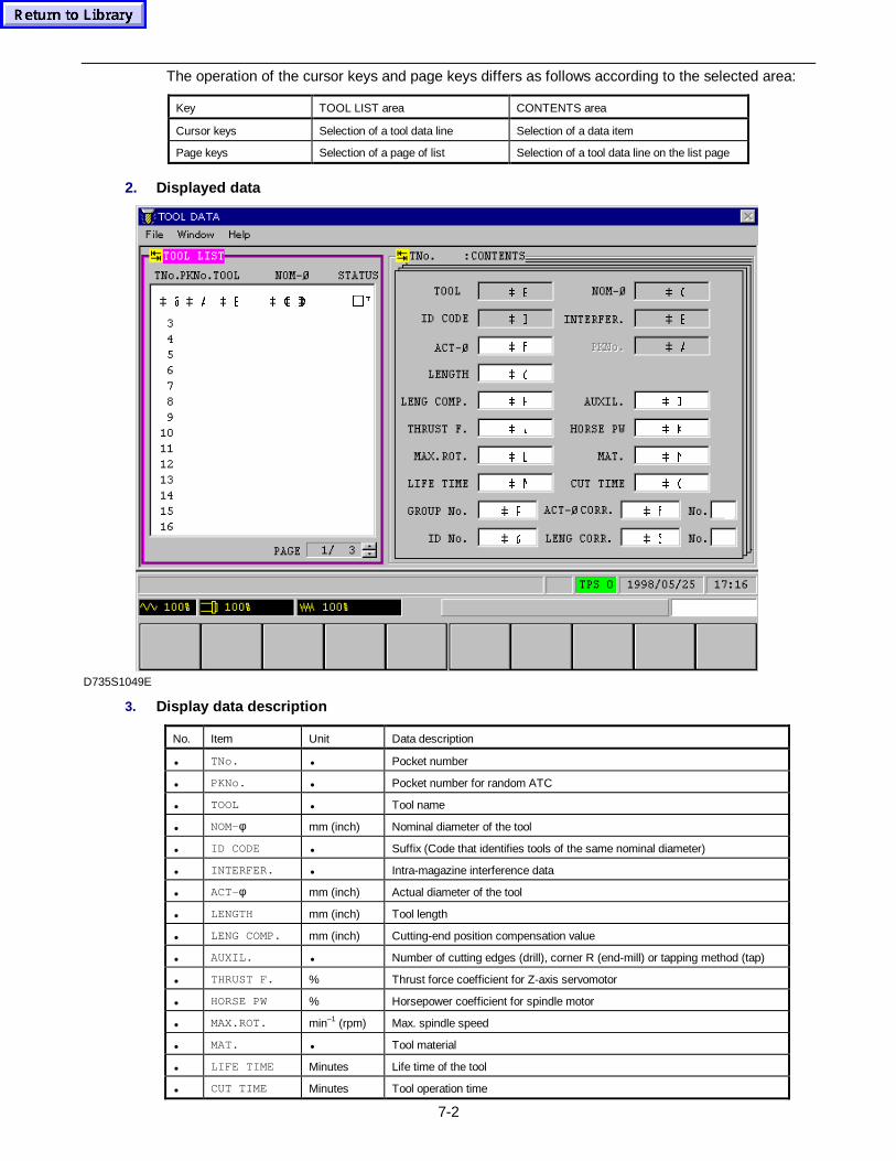
7-2
The operation of the cursor keys and page keys differs as follows according to the selected area:
Key TOOL LIST area CONTENTS area
Cursor keys Selection of a tool data line Selection of a data item
Page keys Selection of a page of list Selection of a tool data line on the list page
2. Displayed data
 -
 +
 *
 )
 '
 %�� & ' ( % $ #
 4
 3
 1
 /
 .
 ,
 6
 5
 2
 0
 $
 (
 &
D735S1049E
3. Display data description
No. Item Unit Data description
• TNo. • Pocket number
• PKNo. • Pocket number for random ATC
• TOOL • Tool name
• NOM-φ mm (inch) Nominal diameter of the tool
• ID CODE • Suffix (Code that identifies tools of the same nominal diameter)
• INTERFER. • Intra-magazine interference data
• ACT-φ mm (inch) Actual diameter of the tool
• LENGTH mm (inch) Tool length
• LENG COMP. mm (inch) Cutting-end position compensation value
• AUXIL. • Number of cutting edges (drill), corner R (end-mill) or tapping method (tap)
• THRUST F. % Thrust force coefficient for Z-axis servomotor
• HORSE PW % Horsepower coefficient for spindle motor
• MAX.ROT. min–1 (rpm) Max. spindle speed
• MAT. • Tool material
• LIFE TIME Minutes Life time of the tool
• CUT TIME Minutes Tool operation time
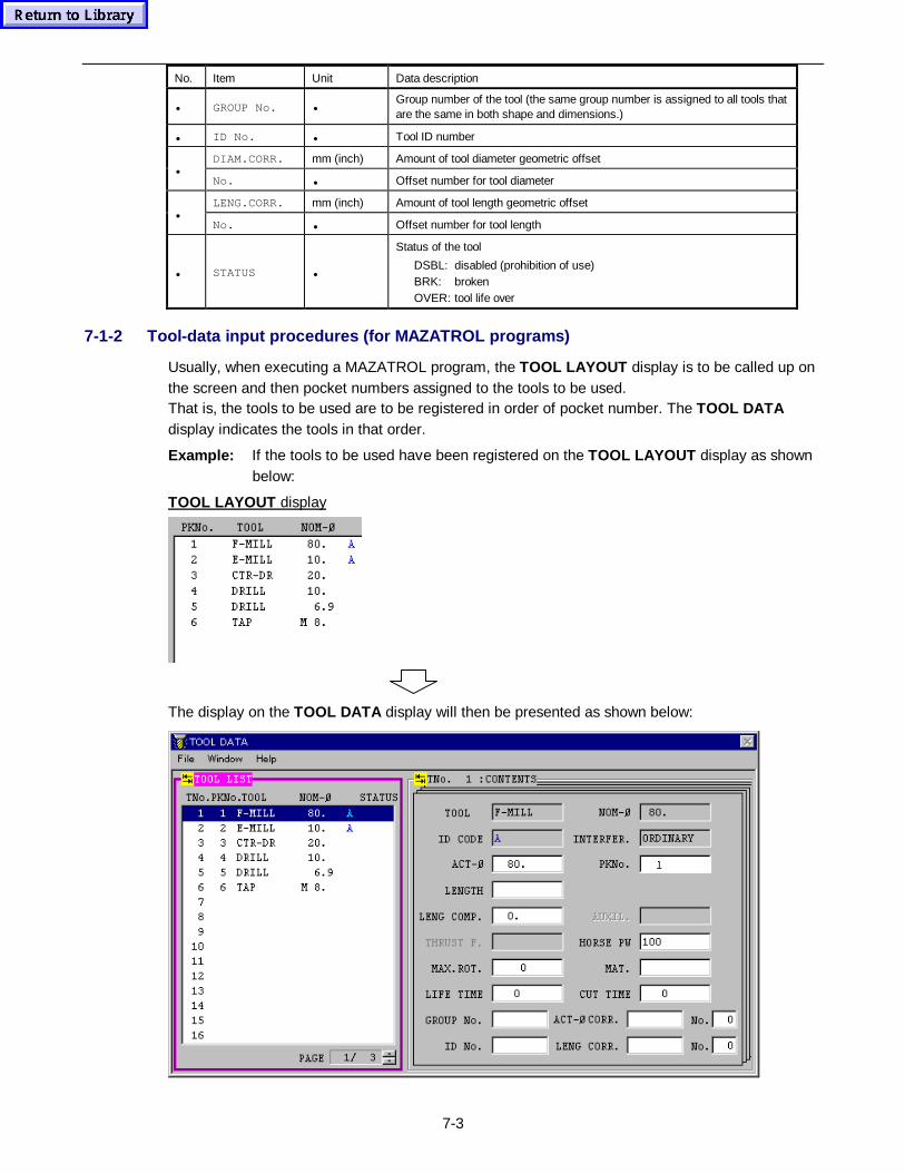
7-3
No. Item Unit Data description
• GROUP No. •Group number of the tool (the same group number is assigned to all tools thatare the same in both shape and dimensions.)
• ID No. • Tool ID number
DIAM.CORR. mm (inch) Amount of tool diameter geometric offset•
No. • Offset number for tool diameter
LENG.CORR. mm (inch) Amount of tool length geometric offset•
No. • Offset number for tool length
• STATUS •
Status of the tool
DSBL: disabled (prohibition of use)BRK: brokenOVER: tool life over
7-1-2 Tool-data input procedures (for MAZATROL programs)
Usually, when executing a MAZATROL program, the TOOL LAYOUT display is to be called up onthe screen and then pocket numbers assigned to the tools to be used.That is, the tools to be used are to be registered in order of pocket number. The TOOL DATAdisplay indicates the tools in that order.
Example: If the tools to be used have been registered on the TOOL LAYOUT display as shownbelow:
TOOL LAYOUT display
The display on the TOOL DATA display will then be presented as shown below:
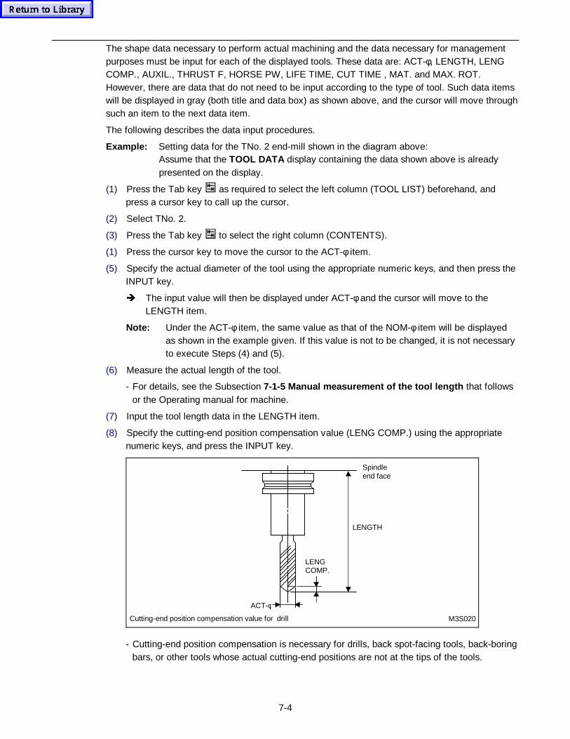
7-4
The shape data necessary to perform actual machining and the data necessary for managementpurposes must be input for each of the displayed tools. These data are: ACT-φ, LENGTH, LENGCOMP., AUXIL., THRUST F, HORSE PW, LIFE TIME, CUT TIME , MAT. and MAX. ROT.However, there are data that do not need to be input according to the type of tool. Such data itemswill be displayed in gray (both title and data box) as shown above, and the cursor will move throughsuch an item to the next data item.
The following describes the data input procedures.
Example: Setting data for the TNo. 2 end-mill shown in the diagram above:Assume that the TOOL DATA display containing the data shown above is alreadypresented on the display.
(1) Press the Tab key as required to select the left column (TOOL LIST) beforehand, andpress a cursor key to call up the cursor.
(2) Select TNo. 2.
(3) Press the Tab key to select the right column (CONTENTS).
(1) Press the cursor key to move the cursor to the ACT-φ item.
(5) Specify the actual diameter of the tool using the appropriate numeric keys, and then press theINPUT key.
Î The input value will then be displayed under ACT-φ and the cursor will move to theLENGTH item.
Note: Under the ACT-φ item, the same value as that of the NOM-φ item will be displayedas shown in the example given. If this value is not to be changed, it is not necessaryto execute Steps (4) and (5).
(6) Measure the actual length of the tool.
- For details, see the Subsection 7-1-5 Manual measurement of the t ool length that followsor the Operating manual for machine.
(7) Input the tool length data in the LENGTH item.
(8) Specify the cutting-end position compensation value (LENG COMP.) using the appropriatenumeric keys, and press the INPUT key.
Cutting-end position compensation value for drill M3S020
LENGCOMP.
LENGTH
Spindleend face
ACT-φ
- Cutting-end position compensation is necessary for drills, back spot-facing tools, back-boringbars, or other tools whose actual cutting-end positions are not at the tips of the tools.
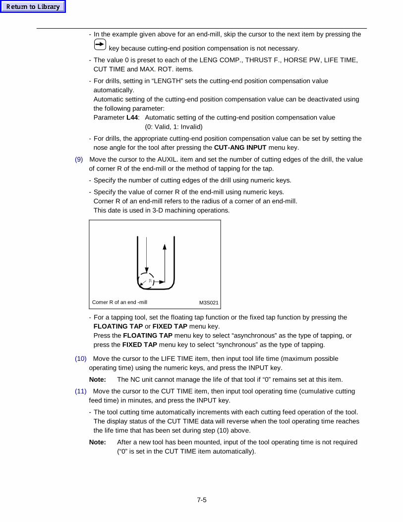
7-5
- In the example given above for an end-mill, skip the cursor to the next item by pressing the
key because cutting-end position compensation is not necessary.
- The value 0 is preset to each of the LENG COMP., THRUST F., HORSE PW, LIFE TIME,CUT TIME and MAX. ROT. items.
- For drills, setting in “LENGTH” sets the cutting-end position compensation valueautomatically.Automatic setting of the cutting-end position compensation value can be deactivated usingthe following parameter:Parameter L44: Automatic setting of the cutting-end position compensation value
(0: Valid, 1: Invalid)
- For drills, the appropriate cutting-end position compensation value can be set by setting thenose angle for the tool after pressing the CUT-ANG INPUT menu key.
(9) Move the cursor to the AUXIL. item and set the number of cutting edges of the drill, the valueof corner R of the end-mill or the method of tapping for the tap.
- Specify the number of cutting edges of the drill using numeric keys.
- Specify the value of corner R of the end-mill using numeric keys.Corner R of an end-mill refers to the radius of a corner of an end-mill.This date is used in 3-D machining operations.
Comer R of an end -mill
R
M3S021
- For a tapping tool, set the floating tap function or the fixed tap function by pressing theFLOATING TAP or FIXED TAP menu key.Press the FLOATING TAP menu key to select “asynchronous” as the type of tapping, orpress the FIXED TAP menu key to select “synchronous” as the type of tapping.
(10) Move the cursor to the LIFE TIME item, then input tool life time (maximum possibleoperating time) using the numeric keys, and press the INPUT key.
Note: The NC unit cannot manage the life of that tool if “0” remains set at this item.
(11) Move the cursor to the CUT TIME item, then input tool operating time (cumulative cuttingfeed time) in minutes, and press the INPUT key.
- The tool cutting time automatically increments with each cutting feed operation of the tool.The display status of the CUT TIME data will reverse when the tool operating time reachesthe life time that has been set during step (10) above.
Note: After a new tool has been mounted, input of the tool operating time is not required(“0” is set in the CUT TIME item automatically).
7-6
(12) Move the cursor to the MAT. item, and press the menu key corresponding to the type ofmaterial to be set.
- If a milling tool that has been registered on the TOOL FILE display is registered here, thecorresponding type of material set previously on that display will be auto-set. (Only if a suffixis set.)
- The material types presented in the menu here refer to the settings on the CUTTINGCONDITION (W.-MAT./T.-MAT.) display. See Section 8-1 for further details.
- Data that has been set in the MAT. item is referred to during automatic setting of cuttingconditions or used as tutorial data relating to cutting conditions in the MAZATROL program,based on the data that has been registered on the CUTTING CONDITION display. SeeSection 8-2 for further details.
(13) Move the cursor to the THRUST F. item, then input data using the numeric keys, and pressthe INPUT key.
- Data that the NC unit is to calculate can be set by pressing the AUTO SET menu key,instead of setting data using the numeric keys.
- When the AUTO SET menu key is pressed, the NC equipment will calculate the maximumpermissible load value of the Z-axis servomotor and automatically set the adequate thrustforce coefficient (%).
- If you have selected TAP as the tool name and “Synchronous” as the method of tapping, seta returning speed rate (%) for that synchronous tapping tool in this item.Returning speed = Returning speed rate/100 × Feed rate(All returning speed rates less than 100% are handled as 100%.)
Note 1: If the load on the Z-axis servomotor exceeds the percentage value that has beeninput to the THR. item, then the cutting feedrate will automatically decrease andthe load will be controlled to within its permissible limits.
Note 2: Input of data to the THRUST F. item becomes necessary only for end-mills, drills,chamfering cutters and face-mills.
Note 3: If synchronous tapping cycle machining is required, FIXED TAP must be selectedfor AUXIL. item of the TOOL DATA display.
(14) Move the cursor to the HORSE PW item and specify the value using the appropreatenumeric keys, and then press the INPUT key.
- When the AUTO SET menu key is pressed instead of specifying the value using numerickeys, the value that is calculated by the NC can be set.
- When the AUTO SET menu key is pressed, the NC equipment will calculate the maximumpermissible load value of the spindle servo motor and automatically set the adequate horsepower coefficient (%).
Note 1: If the load on the spindle servo motor exceeds the percentage value that has beeninput to the HP item, then the cutting feedrate will automatically decrease and theload will be controlled to within its permissible limits.
Note 2: Input of data to the HP item becomes necessary only for face-mills, end mills, boringbars, drills, backspot-facing tools, backboring bars or chamfering cutters.
(15) Move the cursor to the MAX. ROT. item, then input the maximum rotational speed of the toolusing the numeric keys, and press the INPUT key.
Note 1: The maximum rotational speed of the tool will not be limited if “0” remains set in thisitem.
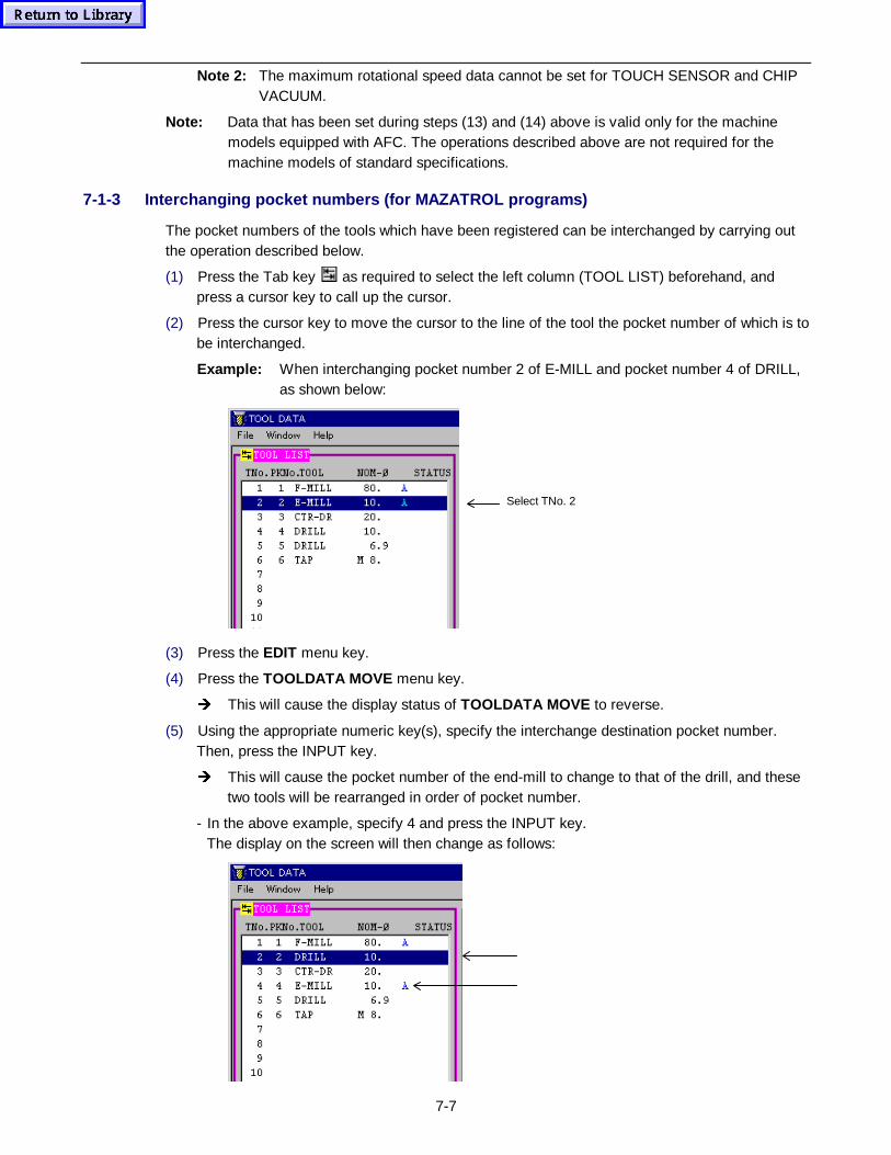
7-7
Note 2: The maximum rotational speed data cannot be set for TOUCH SENSOR and CHIPVACUUM.
Note: Data that has been set during steps (13) and (14) above is valid only for the machinemodels equipped with AFC. The operations described above are not required for themachine models of standard specifications.
7-1-3 Interchanging pocket numbers (for MAZATROL programs)
The pocket numbers of the tools which have been registered can be interchanged by carrying outthe operation described below.
(1) Press the Tab key as required to select the left column (TOOL LIST) beforehand, andpress a cursor key to call up the cursor.
(2) Press the cursor key to move the cursor to the line of the tool the pocket number of which is tobe interchanged.
Example: When interchanging pocket number 2 of E-MILL and pocket number 4 of DRILL,as shown below:
Select TNo. 2
(3) Press the EDIT menu key.
(4) Press the TOOLDATA MOVE menu key.
Î This will cause the display status of TOOLDATA MOVE to reverse.
(5) Using the appropriate numeric key(s), specify the interchange destination pocket number.Then, press the INPUT key.
Î This will cause the pocket number of the end-mill to change to that of the drill, and thesetwo tools will be rearranged in order of pocket number.
- In the above example, specify 4 and press the INPUT key.The display on the screen will then change as follows:
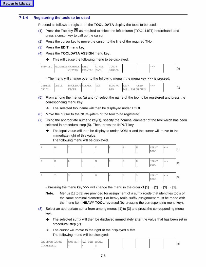
7-8
7-1-4 Registering the tools to be used
Proceed as follows to register on the TOOL DATA display the tools to be used:
(1) Press the Tab key as required to select the left column (TOOL LIST) beforehand, andpress a cursor key to call up the cursor.
(2) Press the cursor key to move the cursor to the line of the required TNo.
(3) Press the EDIT menu key.
(4) Press the TOOLDATA ASSIGN menu key .
Î This will cause the following menu to be displayed:
ENDMILL FACEMILL CHAMFER
CUTTER
BALL
ENDMILL
OTHER
TOOL
TOUCH
SENSOR
>>>(a)
- The menu will change over to the following menu if the menu key >>> is pressed:
CENTER
DRILL
DRILL BACKSPOT
FACER
REAMER TAP BORING
BAR
BACK
BOR. BAR
CHIP
VACUUM
>>>(b)
(5) From among the menus (a) and (b) select the name of the tool to be registered and press thecorresponding menu key.
Î The selected tool name will then be displayed under TOOL.
(6) Move the cursor to the NOM-φ item of the tool to be registered.
(7) Using the appropriate numeric key(s), specify the nominal diameter of the tool which has beenselected in procedural step (5). Then, press the INPUT key
Î The input value will then be displayed under NOM-φ, and the cursor will move to theimmediate right of this value.The following menu will be displayed.
A B C D E F G H HEAVY
TOOL
>>>[1]
J K L M N P Q R HEAVY
TOOL
>>>[2]
S T U V W X Y Z HEAVY
TOOL
>>>[3]
- Pressing the menu key >>> will change the menu in the order of [1] → [2] → [3] → [1].
Note: Menus [1] to [3] are provided for assignment of a suffix (code that identifies tools ofthe same nominal diameter). For heavy tools, suffix assignment must be made withthe menu item HEAVY TOOL reversed (by pressing the corresponding menu key).
(8) Select an appropriate suffix from among menus [1] to [3] and press the corresponding menukey.
Î The selected suffix will then be displayed immediately after the value that has been set inprocedural step (7).
Î The cursor will move to the right of the displayed suffix.The following menu will be displayed:
ORDINARY
DIAMETER
LARGE
L
MAG DIR+
+
MAG DIR-
-
SMALL
S(c)
7-9
- Menu (c) refers to the intra-magazine interference data as follows:
ORDINARY DIAMETER ......Diameter of a tool which completely fits into the pocket.
LARGE L .............................Tool which interferes with both next tools in the pocket.
MAG DIR+ + ........................Tool that interferes with the tool of a larger pocket number.
MAG DIR– – ........................Tool that interferes with the tool of a smaller pocket number.
SMALL S .............................Diameter of a tool which can be placed in a pocket otherthan that which interfere with the tool indicated by “+” or “–”.
(9) Press the corresponding menu key contained in menu (c).
Î The selected type of intra-magazine interference data will be displayed.
Note 1: If shape data or other types of data of the particular tool are to be set followingcompletion of the tool registration operation, then repeat procedural steps (3) through(15) in Subsection 7-1-2.
Note 2: When registering a heavy tool, suffix assignment must be preceded by the selection ofthe menu item HEAVY TOOL in procedural step (8). If a suffix for heavy tools isassigned, this causes the ATC (automatic tool change) speed to decrease, and thusallows safe tool change.
Note 3: Only tools that do not interfere with other tools can be registered.
Note 4: The TNo. display of the tool mounted in the spindle will be highlighted in blue.
7-1-5 Manual measurement of the tool lengths
The actual length of each tool to be used must be measured for setting data under LENGTH on theTOOL DATA display. Measurement of the tool lengths can be made in the full-automatic mode,the semi-automatic mode, or the manual mode. Here, the operating procedure for manual tool-length measurement using the LENGTH TEACH function of the TOOL DATA display is described.For the full-automatic and semi-automatic tool-length measurement procedures, see the OperatingManual for machine.
(1) Mount on the spindle the tool whose length is to be measured.
- Carry out the tool change operation to mount on the spindle the tool which is accomodatedin the magazine pocket. For the operation, see the Operating Manual for machine.
(2) Move the spindle by manual operation and bring the tool tip into contact with the top surfaceof either the reference block or the workpiece of a pre-determined height.
- For H-type machines, the edge locator of the table functions as reference. For the operation,see the Operating manual for machine.
(3) Call up the TOOL DATA display on the screen.
(4) Press the LENGTH TEACH menu key.
Î This will cause the display status of LENGTH TEACH to reverse. Subsequently, thecursor will appear in the position of the LENGTH item of the tool currently mounted onthe spindle.
(5) Specify the height of either the reference block or the workpiece using the appropriatenumeric key(s), and then press the INPUT key.
Î The NC equipment will then calculate the length of the tool mounted on the spindle, andthe calculated value will be automatically set under LENGTH. (See the following figure.)
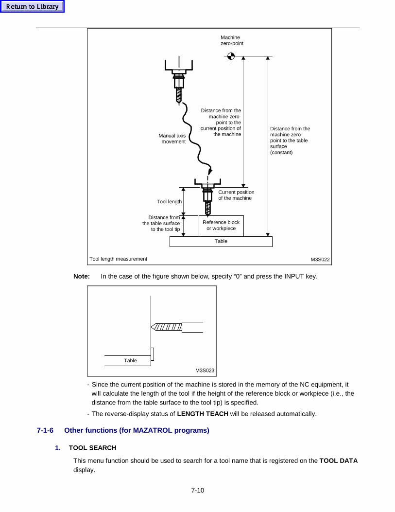
7-10
M3S022Tool length measurement
Machinezero-point
Distance from themachine zero-point to the tablesurface(constant)
Distance fromthe table surface
to the tool tip
Current positionof the machine
Manual axismovement
Reference blockor workpiece
Table
Tool length
Distance from themachine zero-
point to thecurrent position of
the machine
Note: In the case of the figure shown below, specify “0” and press the INPUT key.
Table
M3S023
- Since the current position of the machine is stored in the memory of the NC equipment, itwill calculate the length of the tool if the height of the reference block or workpiece (i.e., thedistance from the table surface to the tool tip) is specified.
- The reverse-display status of LENGTH TEACH will be released automatically.
7-1-6 Other functions (for MAZATROL programs)
1. TOOL SEARCH
This menu function should be used to search for a tool name that is registered on the TOOL DATAdisplay.
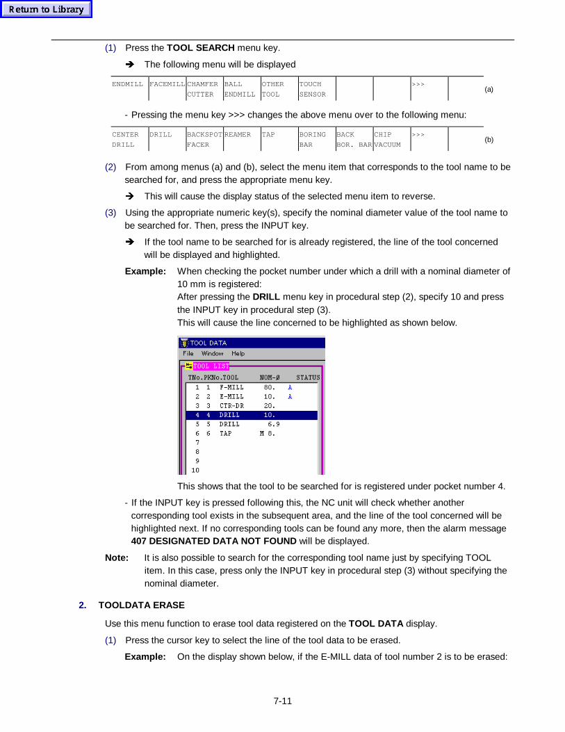
7-11
(1) Press the TOOL SEARCH menu key.
Î The following menu will be displayed
ENDMILL FACEMILL CHAMFER
CUTTER
BALL
ENDMILL
OTHER
TOOL
TOUCH
SENSOR
>>>(a)
- Pressing the menu key >>> changes the above menu over to the following menu:
CENTER
DRILL
DRILL BACKSPOT
FACER
REAMER TAP BORING
BAR
BACK
BOR. BAR
CHIP
VACUUM
>>>(b)
(2) From among menus (a) and (b), select the menu item that corresponds to the tool name to besearched for, and press the appropriate menu key.
Î This will cause the display status of the selected menu item to reverse.
(3) Using the appropriate numeric key(s), specify the nominal diameter value of the tool name tobe searched for. Then, press the INPUT key.
Î If the tool name to be searched for is already registered, the line of the tool concernedwill be displayed and highlighted.
Example: When checking the pocket number under which a drill with a nominal diameter of10 mm is registered:After pressing the DRILL menu key in procedural step (2), specify 10 and pressthe INPUT key in procedural step (3).This will cause the line concerned to be highlighted as shown below.
This shows that the tool to be searched for is registered under pocket number 4.
- If the INPUT key is pressed following this, the NC unit will check whether anothercorresponding tool exists in the subsequent area, and the line of the tool concerned will behighlighted next. If no corresponding tools can be found any more, then the alarm message407 DESIGNATED DATA NOT FOUND will be displayed.
Note: It is also possible to search for the corresponding tool name just by specifying TOOLitem. In this case, press only the INPUT key in procedural step (3) without specifying thenominal diameter.
2. TOOLDATA ERASE
Use this menu function to erase tool data registered on the TOOL DATA display.
(1) Press the cursor key to select the line of the tool data to be erased.
Example: On the display shown below, if the E-MILL data of tool number 2 is to be erased:
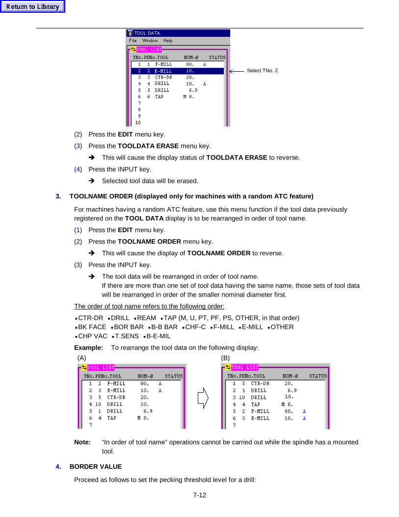
7-12
Select TNo. 2.
(2) Press the EDIT menu key.
(3) Press the TOOLDATA ERASE menu key.
Î This will cause the display status of TOOLDATA ERASE to reverse.
(4) Press the INPUT key.
Î Selected tool data will be erased.
3. TOOLNAME ORDER (displ ayed only for machines with a random ATC feature)
For machines having a random ATC feature, use this menu function if the tool data previouslyregistered on the TOOL DATA display is to be rearranged in order of tool name.
(1) Press the EDIT menu key.
(2) Press the TOOLNAME ORDER menu key.
Î This will cause the display of TOOLNAME ORDER to reverse.
(3) Press the INPUT key.
Î The tool data will be rearranged in order of tool name.If there are more than one set of tool data having the same name, those sets of tool datawill be rearranged in order of the smaller nominal diameter first.
The order of tool name refers to the following order:
• CTR-DR • DRILL • REAM • TAP (M, U, PT, PF, PS, OTHER, in that order)• BK FACE • BOR BAR • B-B BAR • CHF-C • F-MILL • E-MILL • OTHER• CHP VAC • T.SENS • B-E-MIL
Example: To rearrange the tool data on the following display:
(A) (B)
Note: “In order of tool name” operations cannot be carried out while the spindle has a mountedtool.
4. BORDER VALUE
Proceed as follows to set the pecking threshold level for a drill:
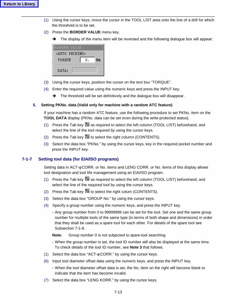
7-13
(1) Using the cursor keys, move the cursor in the TOOL LIST area onto the line of a drill for whichthe threshold is to be set.
(2) Press the BORDER VALUE menu key.
Î The display of the menu item will be reversed and the following dialogue box will appear:
(3) Using the cursor keys, position the cursor on the text box “TORQUE”.
(4) Enter the required value using the numeric keys and press the INPUT key.
Î The threshold will be set definitively and the dialogue box will disappear.
5. Setting PKNo. data (Valid only for machine with a random ATC feature)
If your machine has a random ATC feature, use the following procedure to set PKNo. item on theTOOL DATA display (PKNo. data can be set even during the write-protected status).
(1) Press the Tab key as required to select the left column (TOOL LIST) beforehand, andselect the line of the tool required by using the cursor keys.
(2) Press the Tab key to select the right column (CONTENTS).
(3) Select the data box “PKNo.” by using the cursor keys, key in the required pocket number andpress the INPUT key.
7-1-7 Setting tool data (for EIA/ISO programs)
Setting data in ACT-φ CORR. or No. items and LENG CORR. or No. items of this display allowstool designation and tool life management using an EIA/ISO program.
(1) Press the Tab key as required to select the left column (TOOL LIST) beforehand, andselect the line of the required tool by using the cursor keys.
(2) Press the Tab key to select the right colum (CONTENTS).
(3) Select the data box “GROUP No.” by using the cursor keys.
(4) Specify a group number using the numeric keys, and press the INPUT key.
- Any group number from 0 to 99999999 can be set for the tool. Set one and the same groupnumber for multiple tools of the same type (in terms of both shape and dimensions) in orderthat they shall be used as a spare tool for each other. For details of the spare tool seeSubsection 7-1-8.
Note: Group number 0 is not subjected to spare-tool searching.
- When the group number is set, the tool ID number will also be displayed at the same time.To check details of the tool ID number, see Note 3 that follows.
(1) Select the data box “ACT-φ CORR.” by using the cursor keys.
(6) Input tool diameter offset data using the numeric keys, and press the INPUT key.
- When the tool diameter offset data is set, the No. item on the right will become blank toindicate that the item has become invalid.
(7) Select the data box “LENG KORR.” by using the cursor keys.
7-14
(8) Input tool length offset data using the numeric keys, and press the INPUT key.
- When the tool length offset data is set, the No. item on the right will become blank toindicate that the item has become invalid.
- For the current tool on the spindle only, tool length offset data can be set using the LENG-OFS TEACH menu function. See Subsection 7-1-9 for further details.
(1) Select the data box “No.” on the right of ACT-φ CORR.
(10) Input the offset number under which the tool diameter offset data to be referred to has beenset on the TOOL OFFSET display, and press the INPUT key.
- When the tool diameter offset number is set, the ACT-φ CORR. item will become blank toindicate that the item has become invalid.
- See Section 7-3 for further details of the TOOL OFFSET display.
(11) Select the data box “No.” on the right of LENG CORR.
(12) Input the offset number under which the tool length offset data to be referred to has been seton the TOOL OFFSET display, and press the INPUT key.
- When the tool length offset number is set, the LENG CORR. item will become blank toindicate that the item has become invalid.
- See Section 7-3 for further details of the TOOL OFFSET display.
Note 1: Tool length offset data and tool diameter offset data are to be set by either setting thedata directly on this display or setting the offset numbers corresponding to the offset datathat has been previously set on the TOOL OFFSET display.
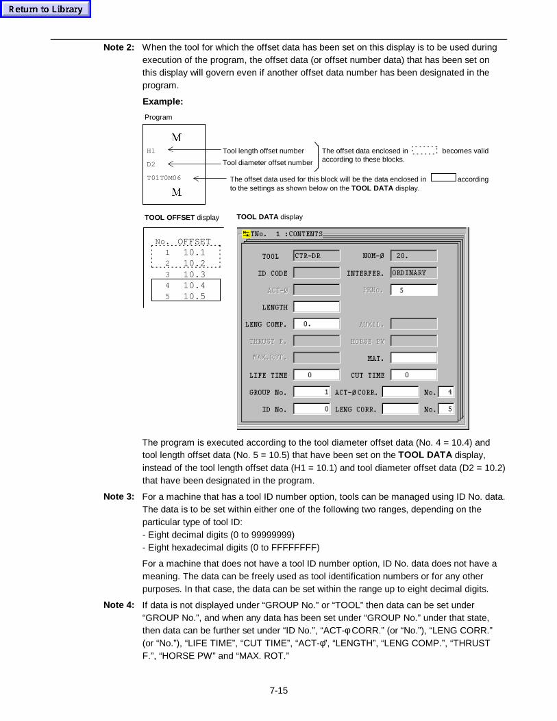
7-15
Note 2: When the tool for which the offset data has been set on this display is to be used duringexecution of the program, the offset data (or offset number data) that has been set onthis display will govern even if another offset data number has been designated in theprogram.
Example:
0
H1
D2
T01T0M06
0
Tool length offset number
Tool diameter offset number
The offset data enclosed in becomes validaccording to these blocks.
The offset data used for this block will be the data enclosed in accordingto the settings as shown below on the TOOL DATA display.
No.
1
2
3
4
5
OFFSET10.110.210.310.410.5
Program
TOOL OFFSET display TOOL DATA display
0
The program is executed according to the tool diameter offset data (No. 4 = 10.4) andtool length offset data (No. 5 = 10.5) that have been set on the TOOL DATA display,instead of the tool length offset data (H1 = 10.1) and tool diameter offset data (D2 = 10.2)that have been designated in the program.
Note 3: For a machine that has a tool ID number option, tools can be managed using ID No. data.The data is to be set within either one of the following two ranges, depending on theparticular type of tool ID:- Eight decimal digits (0 to 99999999)- Eight hexadecimal digits (0 to FFFFFFFF)
For a machine that does not have a tool ID number option, ID No. data does not have ameaning. The data can be freely used as tool identification numbers or for any otherpurposes. In that case, the data can be set within the range up to eight decimal digits.
Note 4: If data is not displayed under “GROUP No.” or “TOOL” then data can be set under“GROUP No.”, and when any data has been set under “GROUP No.” under that state,then data can be further set under “ID No.”, “ACT-φ CORR.” (or “No.”), “LENG CORR.”(or “No.”), “LIFE TIME”, “CUT TIME”, “ACT-φ”, “LENGTH”, “LENG COMP.”, “THRUSTF.”, “HORSE PW” and “MAX. ROT.”
7-16
7-1-8 Setting tool group numbers
If a group number is set for the tools that are to be used during execution of the program, the nextspare tool to be used will be auto-selected from tools of the same group number.
1. Selection of sp are tools
As listed below, two methods are available to select spare tools. Either is to be selected by setting0 or 1 in bit 2 of parameter F84.
- F84 bit 2 = 0: Group number scheme- F84 bit 2 = 1: Tool name scheme
A. Group number scheme
Tools of the same group number are all regarded as spare ones, and tools that have neither yetreached their lives nor become damaged are automatically selected in order with the smallest toolnumber first.
B. Tool n ame scheme
Tools of the same tool name, the same nominal diameter, and the same suffix are all regarded asspare ones, and tools that have neither yet reached their lives nor become damaged areautomatically selected in order with the smallest tool number first.
Note: If all spare tools have reached their lives or become damaged, life-expired one havingthe largest tool number will be selected first.
2. Designation of tool numb ers in the EIA/ISO program
As listed below, two methods are available to designate tool numbers in the EIA/ISO program.Either is to be selected by setting 0 or 1 in bit 4 of parameter F94.
- F94 bit 4 = 0: Group number designation scheme- F94 bit 4 = 1: Tool number designation scheme
A. Group number designation scheme
The T-command in the program is taken as the command for group number (GROUP No.). Toolswith the same GROUP No. as that of the commanded GROUP No. are selected as spare tools.
In this group number designation sheme, T01 in the program is taken as a command for group No.1. In case the group number “1” has been assigned for TNo. 2 and TNo. 3 on the TOOL DATAdisplay, the tool of TNo. 3 is selected if the life of the tool of TNo. 2 has already expired.
B. Tool number designation scheme
The T-command in the program is taken as the command for tool number (TNo.). Tools with thesame GROUP No. as that of the commanded TNo. are selected as spare tools.
In this tool number designation sheme, T01 in the program is taken as a command for TNo. 1. Incase the group number “2” has been assigned for TNo. 1 and TNo. 4 on the TOOL DATA display,the tool of TNo. 4 is selected if the life of the tool of TNo. 1 has already expired.
Note: For both schemes, if there are multiple tools of the same group number, the appropriatetool will be selected according to the particular method of selecting spare tools.
7-17
7-1-9 Manual measurement of tool lengths (Setting tool length offset data using the LENG-OFS TEACH menu function)
The LENG-OFS TEACH menu function can be used to set tool length data in the LENG CORR.
(1) Manually move the axes, and bring the nose of the tool into contact with the top of either areference block or a workpiece whose height is predetermined.
- Refer to the Operating Manual of the machine for further details of manual operations.
(2) Press the LENG-OFS TEACH menu key.
Î The display status of the LENG-OFS TEACH menu item will then reverse, and the LENGCORR. item of the tool currently mounted on the spindle will be selected.
(3) Input the height of either the reference block or the workpiece, and press the INPUT key.
Î The NC unit will then calculate the tool length (see the figure given in Subsection 7-1-5),and auto-set the calculated data under the LENG CORR. item.
- The LENG-OFS TEACH menu item will return to its normal display status.
7-1-10 Other functions (for EIA/ISO programs)
1. ADD. DATA CANCEL menu function
Use this menu function to erase only GROUP No. and ID No. data.
(1) Press the Tab key as required to select the left column (TOOL LIST) beforehand, andselect the line of the required tool by using the cursor keys.
(2) Press the EDIT menu key.
(3) Press the ADD. DATA CANCEL menu key.
(4) Press the INPUT key.
Î The added data (GROUP/ID No.) of the tool selected in Step (1) will then be erased.
7-1-11 MAZATROL tool data “INVALIDATION” (Option)
1. Overview
“INVALIDATION” is an option that makes registered MAZATROL tool data on the TOOL DATAdisplay invalid during program execution. The invalidated tool data is indicated by DSBL under“STATUS” for distinction from valid tool data.Using this option, you can select tools from all those of the same type or set the tools not to beused without deleting the tool data before executing the program.
2. Making the tool data valid/invalid
(1) Press the Tab key as required to select the left column (TOOL LIST) beforehand, andselect the line of the required tool by using the cursor keys.
(2) Press the EDIT menu key.
(3) To make the data selected in (1) valid/invalid, press the menu key TOOLDATA VALID orTOOL DATA INVALID respectively.
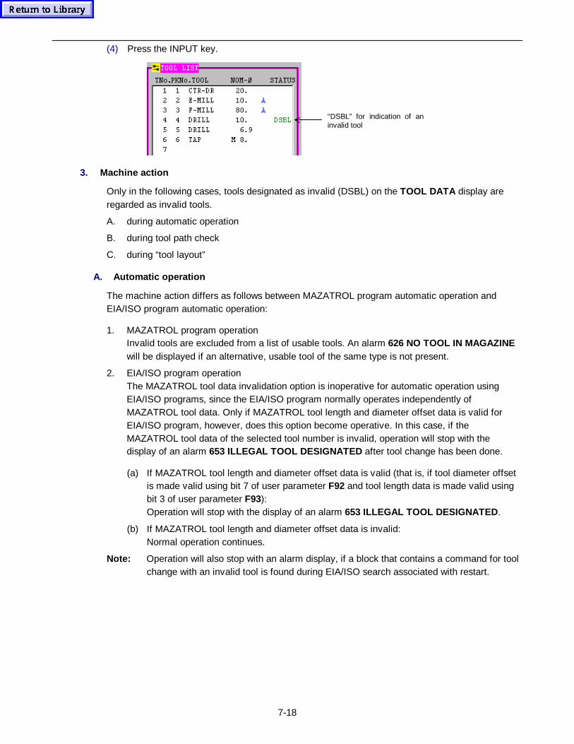
7-18
(4) Press the INPUT key.
“DSBL” for indication of aninvalid tool
3. Machine action
Only in the following cases, tools designated as invalid (DSBL) on the TOOL DATA display areregarded as invalid tools.
A. during automatic operation
B. during tool path check
C. during “tool layout”
A. Automatic operation
The machine action differs as follows between MAZATROL program automatic operation andEIA/ISO program automatic operation:
1. MAZATROL program operationInvalid tools are excluded from a list of usable tools. An alarm 626 NO TOOL IN MAGAZINEwill be displayed if an alternative, usable tool of the same type is not present.
2. EIA/ISO program operationThe MAZATROL tool data invalidation option is inoperative for automatic operation usingEIA/ISO programs, since the EIA/ISO program normally operates independently ofMAZATROL tool data. Only if MAZATROL tool length and diameter offset data is valid forEIA/ISO program, however, does this option become operative. In this case, if theMAZATROL tool data of the selected tool number is invalid, operation will stop with thedisplay of an alarm 653 ILLEGAL TOOL DESIGNATED after tool change has been done.
(a) If MAZATROL tool length and diameter offset data is valid (that is, if tool diameter offsetis made valid using bit 7 of user parameter F92 and tool length data is made valid usingbit 3 of user parameter F93):Operation will stop with the display of an alarm 653 ILLEGAL TOOL DESIGNATED .
(b) If MAZATROL tool length and diameter offset data is invalid:Normal operation continues.
Note: Operation will also stop with an alarm display, if a block that contains a command for toolchange with an invalid tool is found during EIA/ISO search associated with restart.
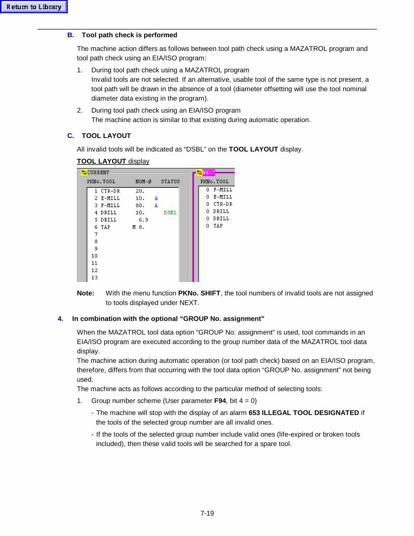
7-19
B. Tool path ch eck is performed
The machine action differs as follows between tool path check using a MAZATROL program andtool path check using an EIA/ISO program:
1. During tool path check using a MAZATROL programInvalid tools are not selected. If an alternative, usable tool of the same type is not present, atool path will be drawn in the absence of a tool (diameter offsetting will use the tool nominaldiameter data existing in the program).
2. During tool path check using an EIA/ISO programThe machine action is similar to that existing during automatic operation.
C. TOOL LAYOUT
All invalid tools will be indicated as “DSBL” on the TOOL LAYOUT display.
TOOL LAYOUT display
Note: With the menu function PKNo. SHIFT , the tool numbers of invalid tools are not assignedto tools displayed under NEXT.
4. In combination with the optional “GROUP No. assignment”
When the MAZATROL tool data option “GROUP No. assignment” is used, tool commands in anEIA/ISO program are executed according to the group number data of the MAZATROL tool datadisplay.The machine action during automatic operation (or tool path check) based on an EIA/ISO program,therefore, differs from that occurring with the tool data option “GROUP No. assignment” not beingused.The machine acts as follows according to the particular method of selecting tools:
1. Group number scheme (User parameter F94, bit 4 = 0)
- The machine will stop with the display of an alarm 653 ILLEGAL TOOL DESIGNATED ifthe tools of the selected group number are all invalid ones.
- If the tools of the selected group number include valid ones (life-expired or broken toolsincluded), then these valid tools will be searched for a spare tool.
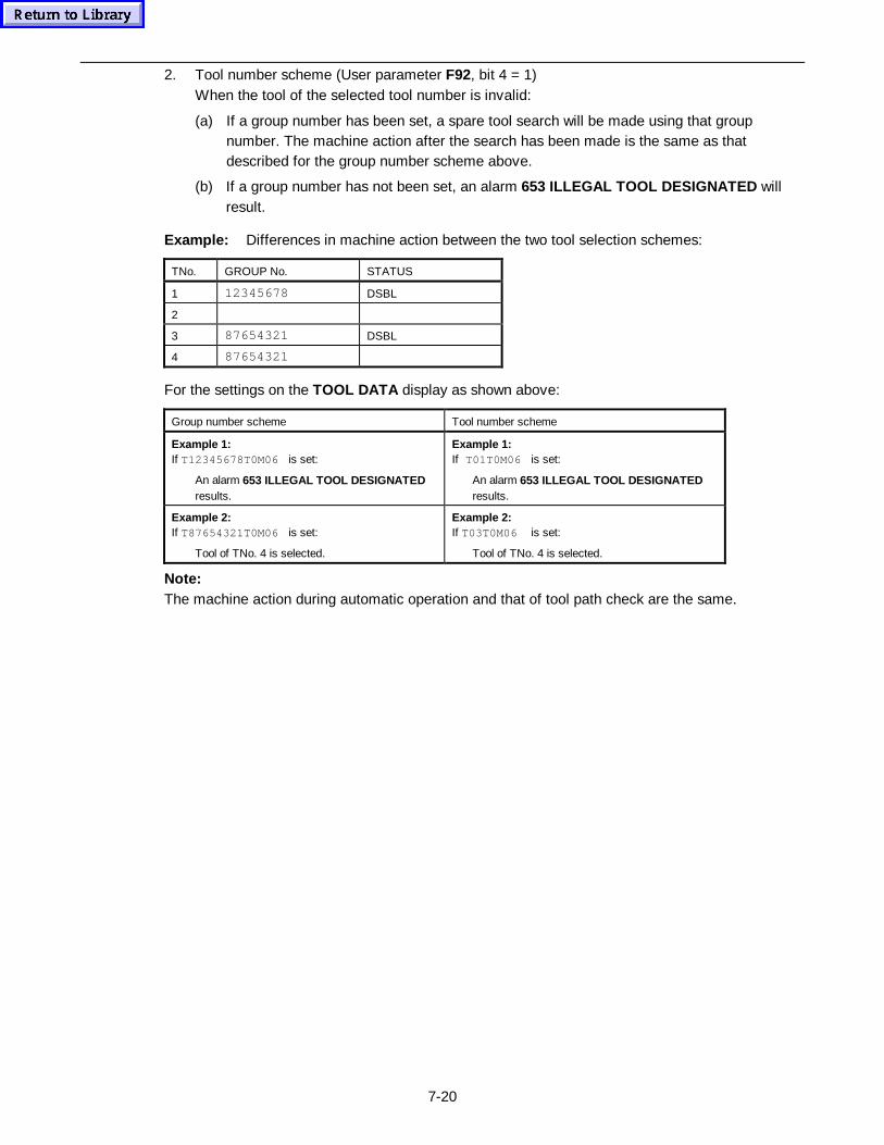
7-20
2. Tool number scheme (User parameter F92, bit 4 = 1)When the tool of the selected tool number is invalid:
(a) If a group number has been set, a spare tool search will be made using that groupnumber. The machine action after the search has been made is the same as thatdescribed for the group number scheme above.
(b) If a group number has not been set, an alarm 653 ILLEGAL TOOL DESIGNATED willresult.
Example: Differences in machine action between the two tool selection schemes:
TNo. GROUP No. STATUS
1 12345678 DSBL
2
3 87654321 DSBL
4 87654321
For the settings on the TOOL DATA display as shown above:
Group number scheme Tool number scheme
Example 1:If T12345678T0M06 is set:
An alarm 653 ILLEGAL TOOL DESIGNATEDresults.
Example 1:If T01T0M06 is set:
An alarm 653 ILLEGAL TOOL DESIGNATEDresults.
Example 2:If T87654321T0M06 is set:
Tool of TNo. 4 is selected.
Example 2:If T03T0M06 is set:
Tool of TNo. 4 is selected.
Note:The machine action during automatic operation and that of tool path check are the same.
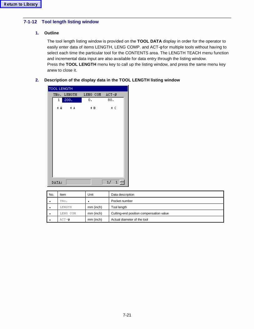
7-21
7-1-12 Tool length listing window
1. Outline
The tool length listing window is provided on the TOOL DATA display in order for the operator toeasily enter data of items LENGTH, LENG COMP. and ACT-φ for multiple tools without having toselect each time the particular tool for the CONTENTS area. The LENGTH TEACH menu functionand incremental data input are also available for data entry through the listing window.Press the TOOL LENGTH menu key to call up the listing window, and press the same menu keyanew to close it.
2. Descript ion of the display data in the TOOL LENGTH listing window
 #  $  %  &
No. Item Unit Data description
• TNo. • Pocket number
• LENGTH mm (inch) Tool length
• LENG COM mm (inch) Cutting-end position compensation value
• ACT-φ mm (inch) Actual diameter of the tool
7-22
7-2 TOOL FILE Display
Function:
- This display is used when registering the data of the milling tools to be used, such as end-mills,face-mills, chamfering cutters, ball end-mills, etc.
Remarks:
- The TOOL FILE display is divided into the following four displays according to the type ofmilling tool to be used:
1. TOOL FILE (END MILL) display2. TOOL FILE (FACE MILL) display3. TOOL FILE (CHAMFER) display4. TOOL FILE (BALL E-MILL) display
- Up to a maximum of 256 milling tools can be registered on the TOOL FILE display.
- Milling tools that are not registered on this display cannot be used when creating a program orwhen executing a program in the automatic operation mode. Milling tools on hand, therefore,should be registered on this display.
- If the TOOL FILE display has been changed over from another display, the TOOL FILE (ENDMILL) display will be selected automatically.If another TOOL FILE display should be called up:
1. Pressing the FACEMILL menu key changes the current display over to the TOOL FILE(FACE MILL) display.
2. Pressing the CHAMFER CUTTER menu key changes the current display over to theTOOL FILE (CHAMFER) display.
3. Pressing the BALL ENDMILL menu key changes the current display over to the TOOLFILE (BALL E-MILL) display.
4. Pressing the ENDMILL menu key changes the current display back to the TOOL FILE(END MILL) display.
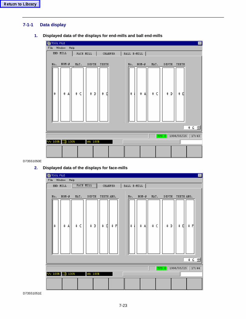
7-23
7-1-1 Data display
1. Displayed data of the displays for end-m ills and ball end-mills
 ' & $ #  (  '
 *
 & $ #  (
D735S1050E
2. Displayed data of the displays for face-m ills
 ' & $ #  ) (
 *
 ' & $ #  ) (
D735S1051E
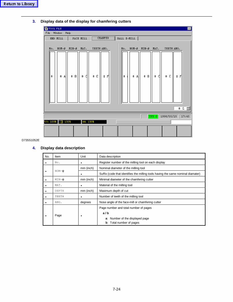
7-24
3. Display data of the display for chamfering cutters
 ) &
 *
 % $ #  ( ) & % $ #  (
D735S1052E
4. Display data description
No. Item Unit Data description
• No. • Register number of the milling tool on each display
mm (inch) Nominal diameter of the milling tool• NOM-φ
• Suffix (code that identifies the milling tools having the same nominal diamater)
• MIN- φ mm (inch) Minimal diameter of the chamfering cutter
• MAT. • Material of the milling tool
• DEPTH mm (inch) Maximum depth of cut
• TEETH • Number of teeth of the milling tool
• ANG. degrees Nose angle of the face-mill or chamfering cutter
• Page •
Page number and total number of pages
a / b
a: Number of the displayed pageb: Total number of pages
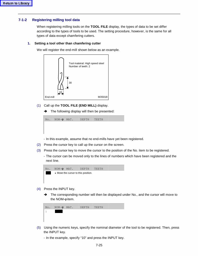
7-25
7-1-2 Registering milling tool data
When registering milling tools on the TOOL FILE display, the types of data to be set differaccording to the types of tools to be used. The setting procedure, however, is the same for alltypes of data except chamfering cutters.
1. Setting a tool other than chamfering cutter
We will register the end-mill shown below as an example.
Tool mateiral: High speed steelNumber of teeth: 2
30
10
End-mill M3S018
(1) Call up the TOOL FILE (END MILL) display.
Î The following display will then be presented:
No. NOM-φ MAT. DEPTH TEETH
- In this example, assume that no end-mills have yet been registered.
(2) Press the cursor key to call up the cursor on the screen.
(3) Press the cursor key to move the cursor to the position of the No. item to be registered.
- The cursor can be moved only to the lines of numbers which have been registered and thenext line.
No. NOM-φ MAT. DEPTH TEETH
• Move the cursor to this position.
(4) Press the INPUT key.
Î The corresponding number will then be displayed under No., and the cursor will move tothe NOM-φ item.
No. NOM-φ MAT. DEPTH TEETH
1
(5) Using the numeric keys, specify the nominal diameter of the tool to be registered. Then, pressthe INPUT key.
- In the example, specify “10” and press the INPUT key.
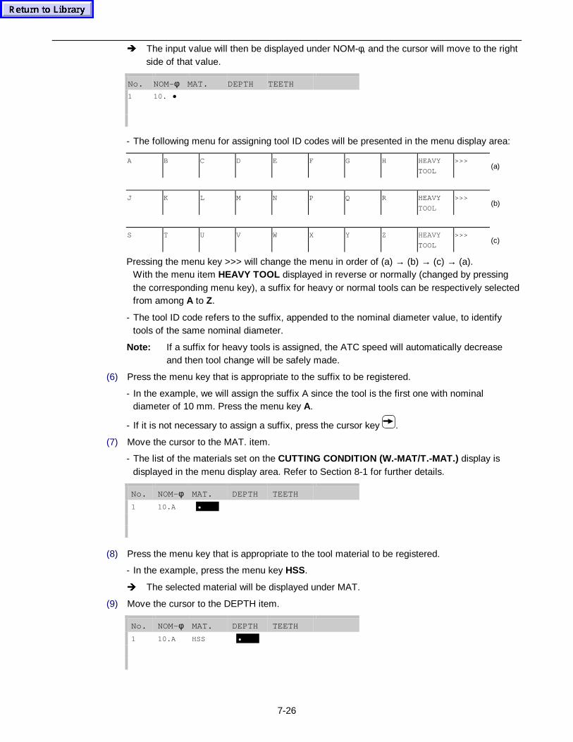
7-26
Î The input value will then be displayed under NOM-φ, and the cursor will move to the rightside of that value.
No. NOM-φ MAT. DEPTH TEETH
1 10. •
- The following menu for assigning tool ID codes will be presented in the menu display area:
A B C D E F G H HEAVY
TOOL
>>>(a)
J K L M N P Q R HEAVY
TOOL
>>>(b)
S T U V W X Y Z HEAVY
TOOL
>>>(c)
Pressing the menu key >>> will change the menu in order of (a) → (b) → (c) → (a).With the menu item HEAVY TOOL displayed in reverse or normally (changed by pressingthe corresponding menu key), a suffix for heavy or normal tools can be respectively selectedfrom among A to Z.
- The tool ID code refers to the suffix, appended to the nominal diameter value, to identifytools of the same nominal diameter.
Note: If a suffix for heavy tools is assigned, the ATC speed will automatically decreaseand then tool change will be safely made.
(6) Press the menu key that is appropriate to the suffix to be registered.
- In the example, we will assign the suffix A since the tool is the first one with nominaldiameter of 10 mm. Press the menu key A.
- If it is not necessary to assign a suffix, press the cursor key .
(7) Move the cursor to the MAT. item.
- The list of the materials set on the CUTTING CONDITION (W.-MAT/T.-MAT.) display isdisplayed in the menu display area. Refer to Section 8-1 for further details.
No. NOM-φ MAT. DEPTH TEETH
1 10.A •
(8) Press the menu key that is appropriate to the tool material to be registered.
- In the example, press the menu key HSS.
Î The selected material will be displayed under MAT.
(9) Move the cursor to the DEPTH item.
No. NOM-φ MAT. DEPTH TEETH
1 10.A HSS •
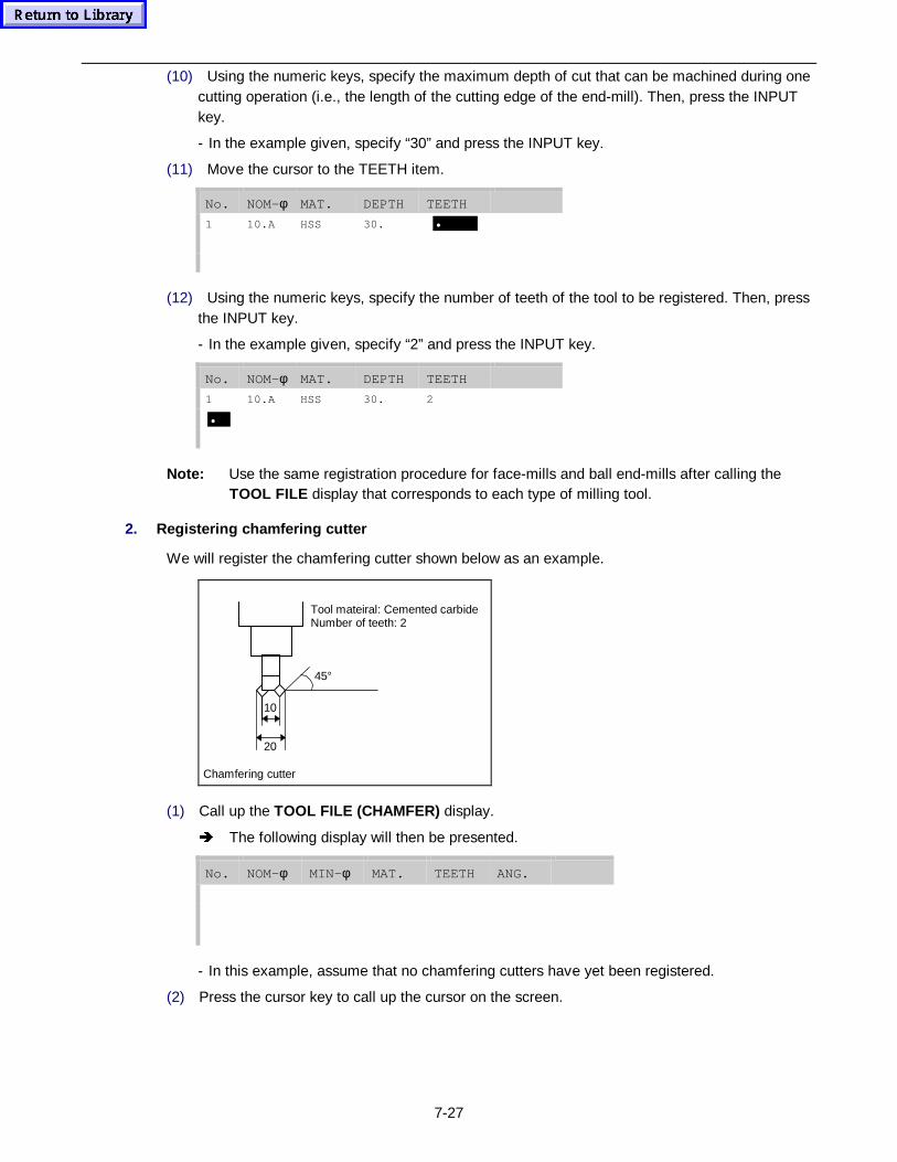
7-27
(10) Using the numeric keys, specify the maximum depth of cut that can be machined during onecutting operation (i.e., the length of the cutting edge of the end-mill). Then, press the INPUTkey.
- In the example given, specify “30” and press the INPUT key.
(11) Move the cursor to the TEETH item.
No. NOM-φ MAT. DEPTH TEETH
1 10.A HSS 30. •
(12) Using the numeric keys, specify the number of teeth of the tool to be registered. Then, pressthe INPUT key.
- In the example given, specify “2” and press the INPUT key.
No. NOM-φ MAT. DEPTH TEETH
1 10.A HSS 30. 2
•
Note: Use the same registration procedure for face-mills and ball end-mills after calling theTOOL FILE display that corresponds to each type of milling tool.
2. Registering chamfering cutter
We will register the chamfering cutter shown below as an example.
10
20
Chamfering cutter
45°
Tool mateiral: Cemented carbideNumber of teeth: 2
(1) Call up the TOOL FILE (CHAMFER) display.
Î The following display will then be presented.
No. NOM-φ MIN- φ MAT. TEETH ANG.
- In this example, assume that no chamfering cutters have yet been registered.
(2) Press the cursor key to call up the cursor on the screen.
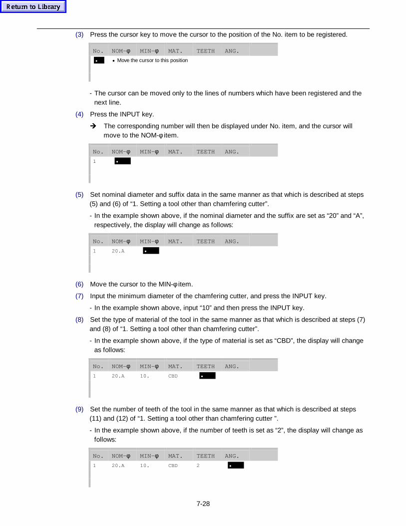
7-28
(3) Press the cursor key to move the cursor to the position of the No. item to be registered.
No. NOM-φ MIN- φ MAT. TEETH ANG.
• • Move the cursor to this position
- The cursor can be moved only to the lines of numbers which have been registered and thenext line.
(4) Press the INPUT key.
Î The corresponding number will then be displayed under No. item, and the cursor willmove to the NOM-φ item.
No. NOM-φ MIN- φ MAT. TEETH ANG.
1 •
(5) Set nominal diameter and suffix data in the same manner as that which is described at steps(5) and (6) of “1. Setting a tool other than chamfering cutter”.
- In the example shown above, if the nominal diameter and the suffix are set as “20” and “A”,respectively, the display will change as follows:
No. NOM-φ MIN- φ MAT. TEETH ANG.
1 20.A •
(6) Move the cursor to the MIN-φ item.
(7) Input the minimum diameter of the chamfering cutter, and press the INPUT key.
- In the example shown above, input “10” and then press the INPUT key.
(8) Set the type of material of the tool in the same manner as that which is described at steps (7)and (8) of “1. Setting a tool other than chamfering cutter”.
- In the example shown above, if the type of material is set as “CBD”, the display will changeas follows:
No. NOM-φ MIN- φ MAT. TEETH ANG.
1 20.A 10. CBD •
(9) Set the number of teeth of the tool in the same manner as that which is described at steps(11) and (12) of “1. Setting a tool other than chamfering cutter ”.
- In the example shown above, if the number of teeth is set as “2”, the display will change asfollows:
No. NOM-φ MIN- φ MAT. TEETH ANG.
1 20.A 10. CBD 2 •
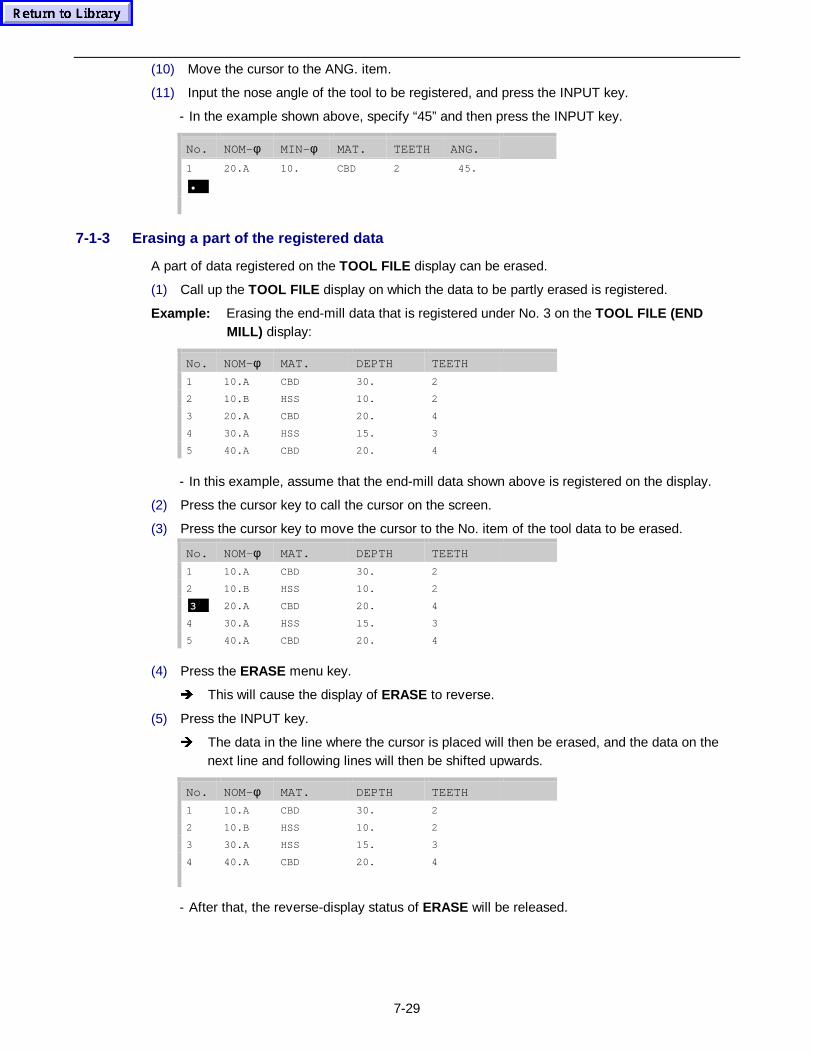
7-29
(10) Move the cursor to the ANG. item.
(11) Input the nose angle of the tool to be registered, and press the INPUT key.
- In the example shown above, specify “45” and then press the INPUT key.
No. NOM-φ MIN- φ MAT. TEETH ANG.
1 20.A 10. CBD 2 45.
•
7-1-3 Erasing a part of the registered data
A part of data registered on the TOOL FILE display can be erased.
(1) Call up the TOOL FILE display on which the data to be partly erased is registered.
Example: Erasing the end-mill data that is registered under No. 3 on the TOOL FILE (ENDMILL) display:
No. NOM-φ MAT. DEPTH TEETH
1 10.A CBD 30. 2
2 10.B HSS 10. 2
3 20.A CBD 20. 4
4 30.A HSS 15. 3
5 40.A CBD 20. 4
- In this example, assume that the end-mill data shown above is registered on the display.
(2) Press the cursor key to call the cursor on the screen.
(3) Press the cursor key to move the cursor to the No. item of the tool data to be erased.
No. NOM-φ MAT. DEPTH TEETH
1 10.A CBD 30. 2
2 10.B HSS 10. 2
3 20.A CBD 20. 4
4 30.A HSS 15. 3
5 40.A CBD 20. 4
(4) Press the ERASE menu key.
Î This will cause the display of ERASE to reverse.
(5) Press the INPUT key.
Î The data in the line where the cursor is placed will then be erased, and the data on thenext line and following lines will then be shifted upwards.
No. NOM-φ MAT. DEPTH TEETH
1 10.A CBD 30. 2
2 10.B HSS 10. 2
3 30.A HSS 15. 3
4 40.A CBD 20. 4
- After that, the reverse-display status of ERASE will be released.
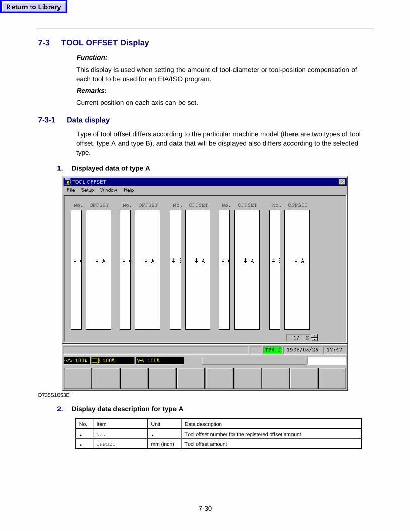
7-30
7-3 TOOL OFFSET Display
Function:
This display is used when setting the amount of tool-diameter or tool-position compensation ofeach tool to be used for an EIA/ISO program.
Remarks:
Current position on each axis can be set.
7-3-1 Data display
Type of tool offset differs according to the particular machine model (there are two types of tooloffset, type A and type B), and data that will be displayed also differs according to the selectedtype.
1. Displayed data of type A
 #
No.
 $
OFFSET
 #
No.
 $
OFFSET
 #
No.
 $
OFFSET
 #
No.
 $
OFFSET
 #
No.
 $
OFFSET
D735S1053E
2. Display data descript ion for type A
No. Item Unit Data description
• No. • Tool offset number for the registered offset amount
• OFFSET mm (inch) Tool offset amount
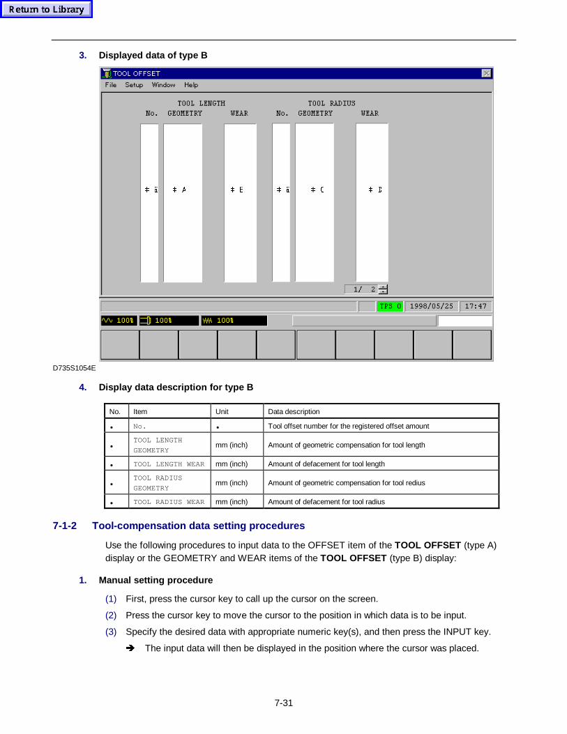
7-31
3. Displayed data of type B
 $  % #  &  ' #
D735S1054E
4. Display data descript ion for type B
No. Item Unit Data description
• No. • Tool offset number for the registered offset amount
•TOOL LENGTH
GEOMETRYmm (inch) Amount of geometric compensation for tool length
• TOOL LENGTH WEAR mm (inch) Amount of defacement for tool length
•TOOL RADIUS
GEOMETRYmm (inch) Amount of geometric compensation for tool redius
• TOOL RADIUS WEAR mm (inch) Amount of defacement for tool radius
7-1-2 Tool-compensation data setting procedures
Use the following procedures to input data to the OFFSET item of the TOOL OFFSET (type A)display or the GEOMETRY and WEAR items of the TOOL OFFSET (type B) display:
1. Manual setting procedure
(1) First, press the cursor key to call up the cursor on the screen.
(2) Press the cursor key to move the cursor to the position in which data is to be input.
(3) Specify the desired data with appropriate numeric key(s), and then press the INPUT key.
Î The input data will then be displayed in the position where the cursor was placed.
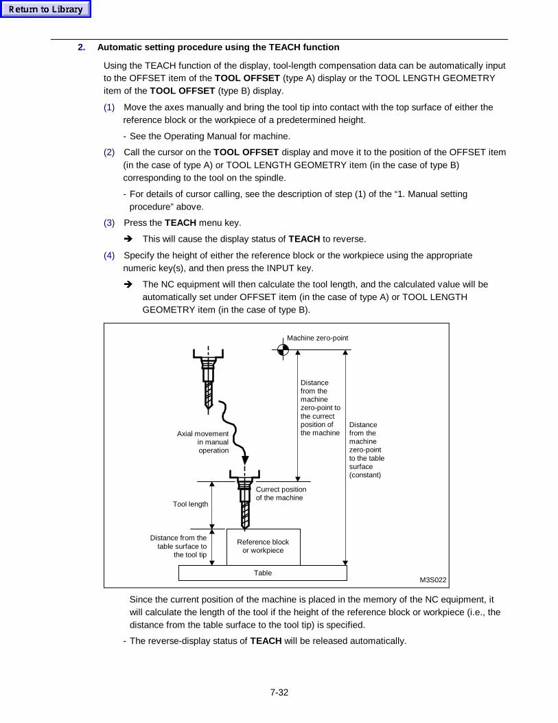
7-32
2. Automatic setting procedure using the TEACH function
Using the TEACH function of the display, tool-length compensation data can be automatically inputto the OFFSET item of the TOOL OFFSET (type A) display or the TOOL LENGTH GEOMETRYitem of the TOOL OFFSET (type B) display.
(1) Move the axes manually and bring the tool tip into contact with the top surface of either thereference block or the workpiece of a predetermined height.
- See the Operating Manual for machine.
(2) Call the cursor on the TOOL OFFSET display and move it to the position of the OFFSET item(in the case of type A) or TOOL LENGTH GEOMETRY item (in the case of type B)corresponding to the tool on the spindle.
- For details of cursor calling, see the description of step (1) of the “1. Manual settingprocedure” above.
(3) Press the TEACH menu key.
Î This will cause the display status of TEACH to reverse.
(4) Specify the height of either the reference block or the workpiece using the appropriatenumeric key(s), and then press the INPUT key.
Î The NC equipment will then calculate the tool length, and the calculated value will beautomatically set under OFFSET item (in the case of type A) or TOOL LENGTHGEOMETRY item (in the case of type B).
M3S022Table
Tool length
Distance from thetable surface to
the tool tip
Currect positionof the machine
Machine zero-point
Distancefrom themachinezero-point tothe currectposition ofthe machine
Distancefrom themachinezero-pointto the tablesurface(constant)
Reference blockor workpiece
Axial movementin manualoperation
Since the current position of the machine is placed in the memory of the NC equipment, itwill calculate the length of the tool if the height of the reference block or workpiece (i.e., thedistance from the table surface to the tool tip) is specified.
- The reverse-display status of TEACH will be released automatically.
7-33
7-1-3 Setting the current position
The current position of the tool nose in the workpiece coordinate system can be set while thePOSITION window remains on the TOOL OFFSET display. See Section 2-4 Window , for furtherdetails of the POSITION window. The procedure for setting the current position of each axis isdescribed below.
(1) After selecting the manual operation mode, press the WINDOW key, select “Position” through“Window” on the menu bar and press the INPUT key to open the POSITION window.
(2) Move the mouse pointer to the current position data of the desired axis by moving a fingeralong the touchpad, and click the left mouse button to display the cursor.
(3) Input a new coordinate value using the numeric keys, and press the INPUT key.
(4) Move the mouse pointer to the desired position on the TOOL OFFSET display by moving afinger along the touchpad, and click the left mouse button.
(5) Clear the POSITION window from the display by pressing the WINDOW key and performing asimilar operation to that in Step (1).
7-1-4 EIA/ISO tool length measurement
1. Outline
- Automatically measured tool lengths can be set in tool offsets automatically.
- Two methods are available to measure tool lengths: fully automatic and semi-automatic.Fully automatic tool length measurement allows the following operations to be carried out:
• Continuous control of a maximum of 13 tools
• Assignment of any offset number
• Automatic movement of any tool in X-axial and Y-axial directions (Automatic movement of atool not having its nose set to the spindle center) [Control parameter: L94]
Semi-automatic tool length measurement allows any offset number to be assigned. [Controlparameter: L95]
- The EIA/ISO tool length measurement function works with an EIA/ISO option. If, however, bit 3 ofparameter F93 (MAZATROL tool length valid/invalid for EIA/ISO programs) is set to “valid”, thisfunction will not work even when the above-mentioned option is provided.
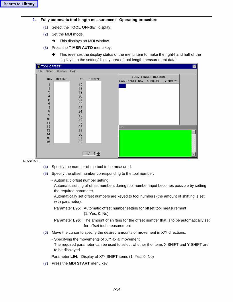
7-34
2. Fully automatic tool length measurement - Operat ing procedure
(1) Select the TOOL OFFSET display.
(2) Set the MDI mode.
Î This displays an MDI window.
(3) Press the T MSR AUTO menu key.
Î This reverses the display status of the menu item to make the right-hand half of thedisplay into the setting/display area of tool length measurement data.
D735S1055E
(4) Specify the number of the tool to be measured.
(5) Specify the offset number corresponding to the tool number.
- Automatic offset number settingAutomatic setting of offset numbers during tool number input becomes possible by settingthe required parameter.Automatically set offset numbers are keyed to tool numbers (the amount of shifting is setwith parameter).
Parameter L95: Automatic offset number setting for offset tool measurement(1: Yes, 0: No)
Parameter L96: The amount of shifting for the offset number that is to be automatically setfor offset tool measurement
(6) Move the cursor to specify the desired amounts of movement in X/Y directions.
- Specifying the movements of X/Y axial movementThe required parameter can be used to select whether the items X SHIFT and Y SHIFT areto be displayed.
Parameter L94: Display of X/Y SHIFT items (1: Yes, 0: No)
(7) Press the MDI START menu key.
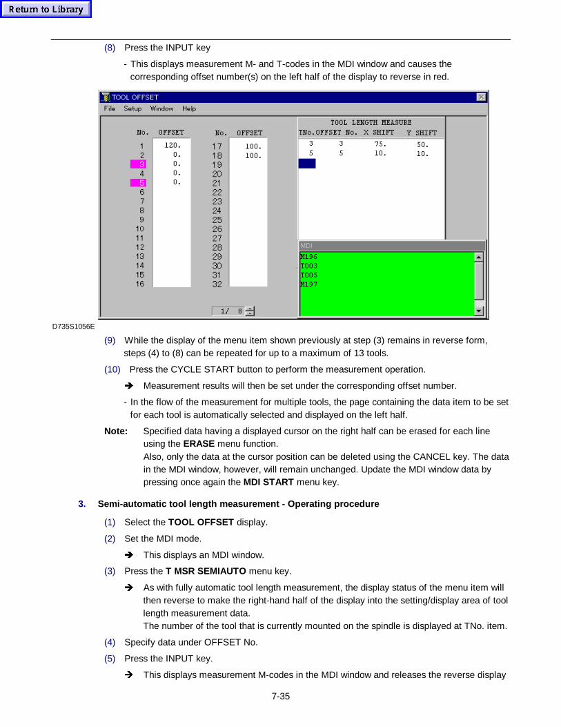
7-35
(8) Press the INPUT key
- This displays measurement M- and T-codes in the MDI window and causes thecorresponding offset number(s) on the left half of the display to reverse in red.
D735S1056E
(9) While the display of the menu item shown previously at step (3) remains in reverse form,steps (4) to (8) can be repeated for up to a maximum of 13 tools.
(10) Press the CYCLE START button to perform the measurement operation.
Î Measurement results will then be set under the corresponding offset number.
- In the flow of the measurement for multiple tools, the page containing the data item to be setfor each tool is automatically selected and displayed on the left half.
Note: Specified data having a displayed cursor on the right half can be erased for each lineusing the ERASE menu function.Also, only the data at the cursor position can be deleted using the CANCEL key. The datain the MDI window, however, will remain unchanged. Update the MDI window data bypressing once again the MDI START menu key.
3. Semi-automatic tool length measurement - Operat ing procedure
(1) Select the TOOL OFFSET display.
(2) Set the MDI mode.
Î This displays an MDI window.
(3) Press the T MSR SEMIAUTO menu key.
Î As with fully automatic tool length measurement, the display status of the menu item willthen reverse to make the right-hand half of the display into the setting/display area of toollength measurement data.The number of the tool that is currently mounted on the spindle is displayed at TNo. item.
(4) Specify data under OFFSET No.
(5) Press the INPUT key.
Î This displays measurement M-codes in the MDI window and releases the reverse display
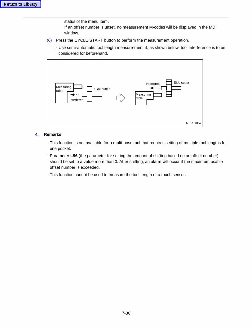
7-36
status of the menu item.If an offset number is unset, no measurement M-codes will be displayed in the MDIwindow.
(6) Press the CYCLE START button to perform the measurement operation.
- Use semi-automatic tool length measure-ment if, as shown below, tool interference is to beconsidered for beforehand.
Measuringtable
Measuringtable Side cutter
Interferes
Side cutterInterferes
D735S1057
4. Remarks
- This function is not available for a multi-nose tool that requires setting of multiple tool lengths forone pocket.
- Parameter L96 (the parameter for setting the amount of shifting based on an offset number)should be set to a value more than 0. After shifting, an alarm will occur if the maximum usableoffset number is exceeded.
- This function cannot be used to measure the tool length of a touch sensor.
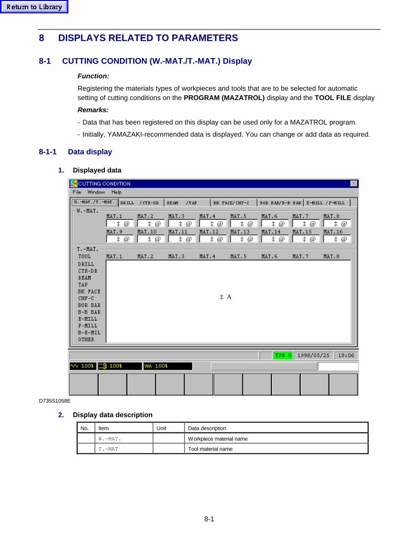
8-1
8 DISPLAYS RELATED TO PARAMETERS
8-1 CUTTING CONDITION (W.-MAT./T.-MAT.) Display
Function:
Registering the materials types of workpieces and tools that are to be selected for automaticsetting of cutting conditions on the PROGRAM (MAZATROL) display and the TOOL FILE display
Remarks:
- Data that has been registered on this display can be used only for a MAZATROL program.
- Initially, YAMAZAKI-recommended data is displayed. You can change or add data as required.
8-1-1 Data display
1. Displayed data
‡ A
‡ @
‡ @
‡ @
‡ @
‡ @
‡ @
‡ @
‡ @
‡ @
‡ @
‡ @
‡ @
‡ @
‡ @
‡ @
‡ @
D735S1058E
2. Display data description
No. Item Unit Data description
� W.-MAT. � Workpiece material name
� T.-MAT � Tool material name
8-2
8-1-2 Registering data
The CUTTING CONDITION (W.-MAT./T.-MAT.) display allows the names of the materials ofworkpieces and tools to be registered using character strings of alphabetic characters and arabicnumerals.
(1) Display the cursor by pressing the cursor key.
(2) Move the cursor to any of the workpiece materials data items from MAT.1 to MAT.16 or thetool materials data items from MAT.1 to MAT.8.
(3) Input the appropriate name using the alphabetic and/or numeric keys, and then press theINPUT key.
- Up to eight characters can be set. The maximum number of workpiece materials types issixteen, and that of tool materials types is eight for each tool.
- Press the CANCEL key to delete the input name.
Note 1: Two parameters are provided for automatic development of the tool sequence in theMAZATROL program. One is D14 (decisive factor for drilling aluminum materials) andone is D15 (decisive factor for drilling non-aluminum materials). Which of the twoparameters will be auto-selected depends on the selected workpiece material.Workpiece material 6 is regarded as aluminium. Parameter D14 will be used if theworkpiece material 6 is selected in the MAZATROL program. Parameter D15 will be usedif another workpiece material is selected.Refer to the Programming Manual (MAZATROL) for further details of automatic tooldevelopment. See the Parameter List for further details of the parameters.
Note 2: The workpiece material names registered in this display are cross-referred to those in thefile (\nm64mdata\eng\cspmat.txt) containing the data for the calculation of the averageoutput indicated on the MACHINING NAVIGATION - PREDICT display. Changing aworkpiece material name in one storage area requires the same operation for the other.Refer to item �of “3. Display data description” in Subsection 6-9-1.
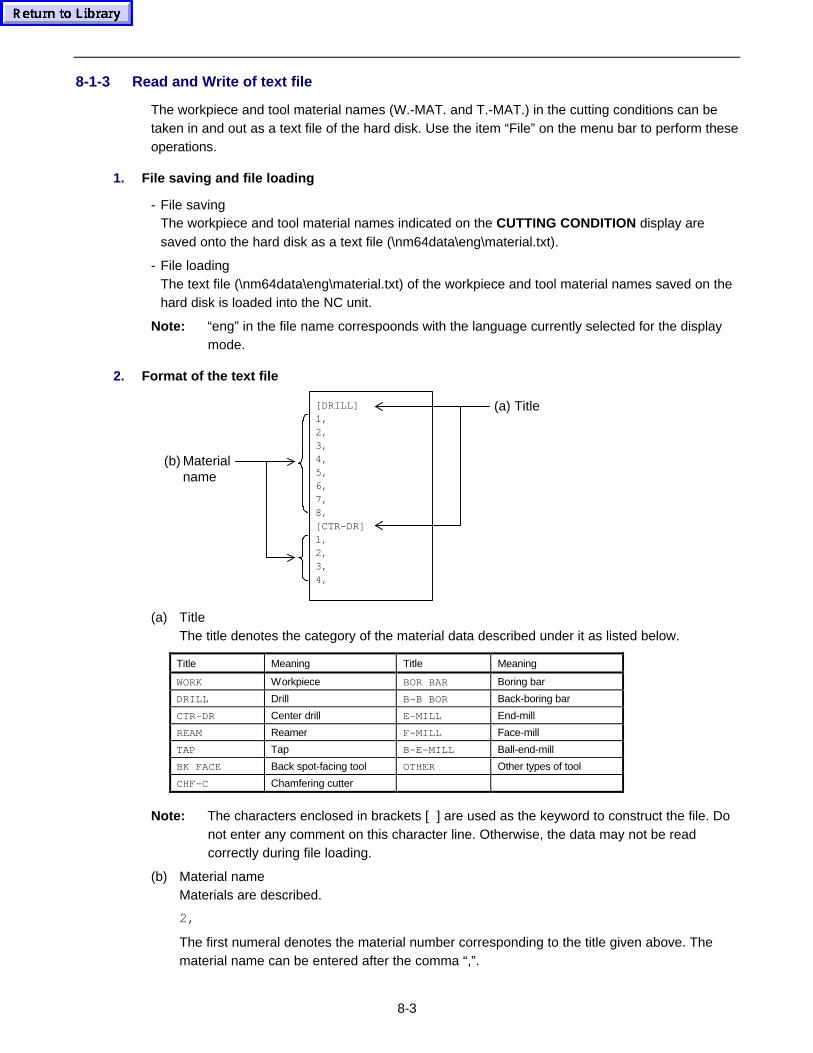
8-3
8-1-3 Read and Write of text file
The workpiece and tool material names (W.-MAT. and T.-MAT.) in the cutting conditions can betaken in and out as a text file of the hard disk. Use the item “File” on the menu bar to perform theseoperations.
1. File saving and file loading
- File savingThe workpiece and tool material names indicated on the CUTTING CONDITION display aresaved onto the hard disk as a text file (\nm64data\eng\material.txt).
- File loadingThe text file (\nm64data\eng\material.txt) of the workpiece and tool material names saved on thehard disk is loaded into the NC unit.
Note: “eng” in the file name correspoonds with the language currently selected for the displaymode.
2. Format of the text file
[DRILL]1,2,3,4,5,6,7,8,[CTR-DR]1,2,3,4,
(a) Title
(b) Materialname
(a) TitleThe title denotes the category of the material data described under it as listed below.
Title Meaning Title Meaning
WORK Workpiece BOR BAR Boring bar
DRILL Drill B-B BOR Back-boring bar
CTR-DR Center drill E-MILL End-mill
REAM Reamer F-MILL Face-mill
TAP Tap B-E-MILL Ball-end-mill
BK FACE Back spot-facing tool OTHER Other types of tool
CHF-C Chamfering cutter
Note: The characters enclosed in brackets [ ] are used as the keyword to construct the file. Donot enter any comment on this character line. Otherwise, the data may not be readcorrectly during file loading.
(b) Material nameMaterials are described.
2,
The first numeral denotes the material number corresponding to the title given above. Thematerial name can be entered after the comma “,”.
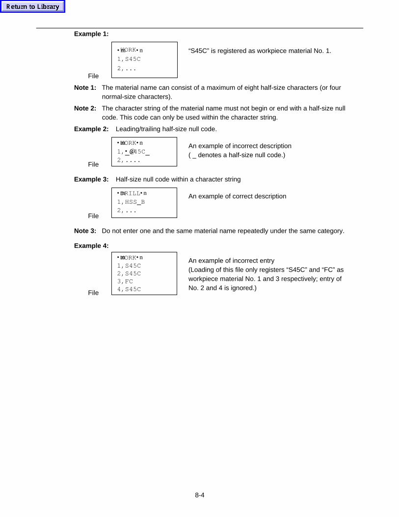
8-4
Example 1:
File
•mWORK•n
1,S45C
2,...
“S45C” is registered as workpiece material No. 1.
Note 1: The material name can consist of a maximum of eight half-size characters (or fournormal-size characters).
Note 2: The character string of the material name must not begin or end with a half-size nullcode. This code can only be used within the character string.
Example 2: Leading/trailing half-size null code.
File
•mWORK•n
1,•@S45C2,....
An example of incorrect description( _ denotes a half-size null code.)
Example 3: Half-size null code within a character string
File
•mDRILL•n
1,HSS B2,...
An example of correct description
Note 3: Do not enter one and the same material name repeatedly under the same category.
Example 4:
File
•mWORK•n1,S45C2,S45C3,FC4,S45C
An example of incorrect entry(Loading of this file only registers “S45C” and “FC” asworkpiece material No. 1 and 3 respectively; entry ofNo. 2 and 4 is ignored.)
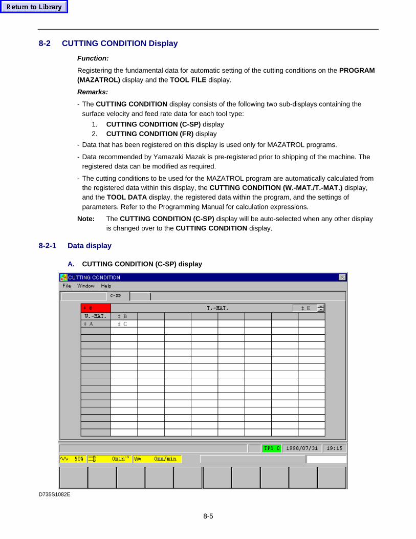
8-5
8-2 CUTTING CONDITION Display
Function:
Registering the fundamental data for automatic setting of the cutting conditions on the PROGRAM(MAZATROL) display and the TOOL FILE display.
Remarks:
- The CUTTING CONDITION display consists of the following two sub-displays containing thesurface velocity and feed rate data for each tool type:
1. CUTTING CONDITION (C-SP) display2. CUTTING CONDITION (FR) display
- Data that has been registered on this display is used only for MAZATROL programs.
- Data recommended by Yamazaki Mazak is pre-registered prior to shipping of the machine. Theregistered data can be modified as required.
- The cutting conditions to be used for the MAZATROL program are automatically calculated fromthe registered data within this display, the CUTTING CONDITION (W.-MAT./T.-MAT.) display,and the TOOL DATA display, the registered data within the program, and the settings ofparameters. Refer to the Programming Manual for calculation expressions.
Note: The CUTTING CONDITION (C-SP) display will be auto-selected when any other displayis changed over to the CUTTING CONDITION display.
8-2-1 Data display
A. CUTTING CONDITION (C-SP) display
‡ @ ‡ E
‡ C
‡ B
‡ A
D735S1082E
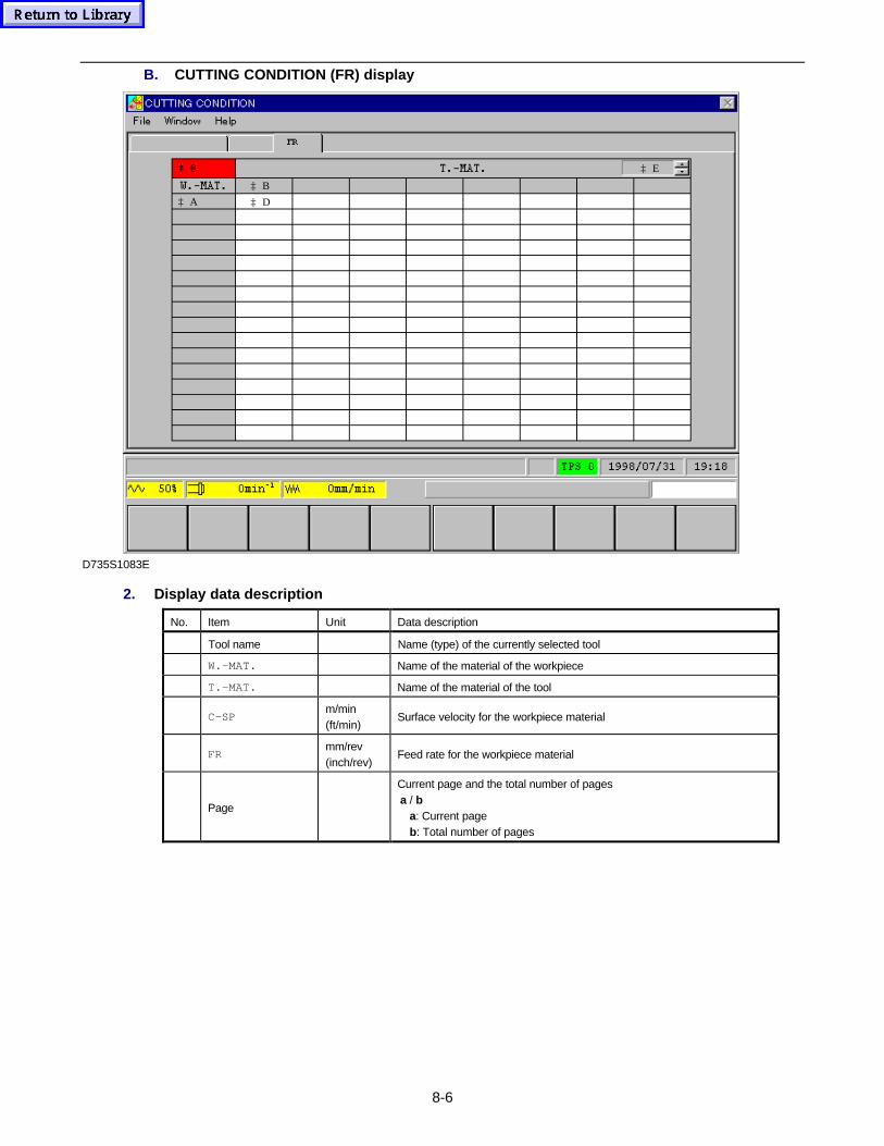
8-6
B. CUTTING CONDITION (FR) display
‡ E
‡ D
‡ B
‡ A
‡ @
D735S1083E
2. Display data description
No. Item Unit Data description
� Tool name � Name (type) of the currently selected tool
� W.-MAT. � Name of the material of the workpiece
� T.-MAT. � Name of the material of the tool
� C-SPm/min(ft/min)
Surface velocity for the workpiece material
� FRmm/rev(inch/rev)
Feed rate for the workpiece material
� Page �
Current page and the total number of pagesa / b a: Current page b: Total number of pages
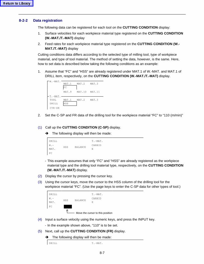
8-7
8-2-2 Data registration
The following data can be registered for each tool on the CUTTING CONDITION display:
1. Surface velocities for each workpiece material type registered on the CUTTING CONDITION(W.-MAT./T.-MAT) display
2. Feed rates for each workpiece material type registered on the CUTTING CONDITION (W.-MAT./T.-MAT) display
Cutting conditions data differs according to the selected type of milling tool, type of workpiecematerial, and type of tool material. The method of setting the data, however, is the same. Here,how to set data is described below taking the following conditions as an example:
1. Assume that “FC” and “HSS” are already registered under MAT.1 of W.-MAT. and MAT.1 ofDRILL item, respectively, on the CUTTING CONDITION (W.-MAT./T.-MAT) display.
MAT.1 MAT.2 MAT.3
FC
MAT.9 MAT.10 MAT.11
TOOL MAT.1 MAT.2 MAT.3
DRILL HSS
CTR-DR
2. Set the C-SP and FR data of the drilling tool for the workpiece material “FC” to “110 (m/min)”
(1) Call up the CUTTING CONDITION (C-SP) display.
è The following display will then be made:
DRILL T.-MAT.
W.-
MAT.HSS BALANCE
CARBID
E
FC
- This example assumes that only “FC” and “HSS” are already registered as the workpiecematerial type and the drilling tool material type, respectively, on the CUTTING CONDITION(W.-MAT./T.-MAT) display.
(2) Display the cursor by pressing the cursor key.
(3) Using the cursor keys, move the cursor to the HSS column of the drilling tool for theworkpiece material “FC”. (Use the page keys to enter the C-SP data for other types of tool.)
DRILL T.-MAT.
W.-
MAT.HSS BALANCE
CARBID
E
FC �
Move the cursor to this position
(4) Input a surface velocity using the numeric keys, and press the INPUT key.
- In the example shown above, “110” is to be set.
(5) Next, call up the CUTTING CONDITION (FR) display.
è The following display will then be made:
DRILL T.-MAT.
W.-MAT.
T.-MAT.
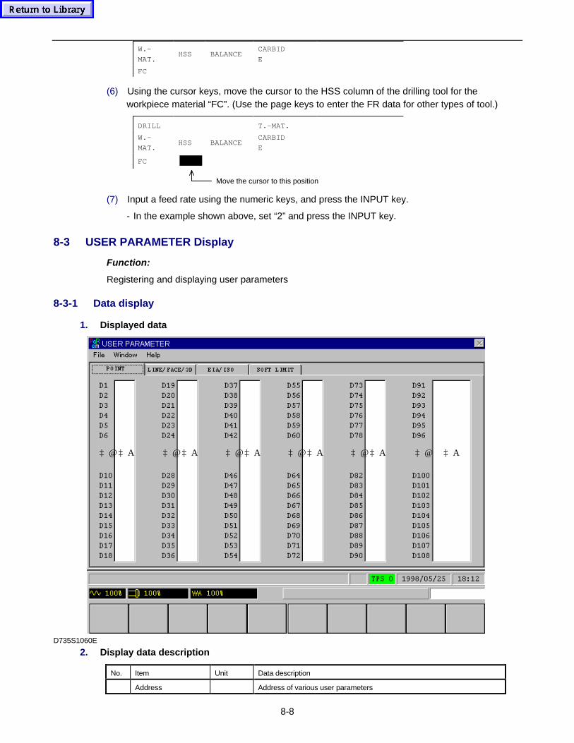
8-8
W.-
MAT.HSS BALANCE
CARBID
E
FC
(6) Using the cursor keys, move the cursor to the HSS column of the drilling tool for theworkpiece material “FC”. (Use the page keys to enter the FR data for other types of tool.)
DRILL T.-MAT.
W.-
MAT.HSS BALANCE
CARBID
E
FC �
Move the cursor to this position
(7) Input a feed rate using the numeric keys, and press the INPUT key.
- In the example shown above, set “2” and press the INPUT key.
8-3 USER PARAMETER Display
Function:
Registering and displaying user parameters
8-3-1 Data display
1. Displayed data
‡ @ ‡ A‡ @ ‡ A‡ @ ‡ A‡ @ ‡ A‡ @ ‡ A‡ @ ‡ A
D735S1060E
2. Display data description
No. Item Unit Data description
� Address � Address of various user parameters

8-9
� Data � Data of various user parameters
Note 1: For further details, see the Prameter List.
Note 2: Confirm the contents of parameters before changing them.
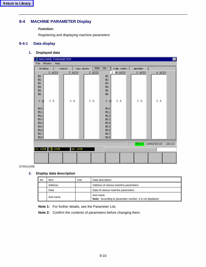
8-10
8-4 MACHINE PARAMETER Display
Function:
Registering and displaying machine parameters
8-4-1 Data display
1. Displayed data
‡ A‡ A‡ @ ‡ A
‡ B
‡ A‡ A‡ @ ‡ A
D735S1105E
2. Display data description
No. Item Unit Data description
� Address � Address of various machine parameters
� Data � Data of various machine parameters
� Axis name �Axis nameNote: According to parameter number, it is not displayed.
Note 1: For further details, see the Parameter List.
Note 2: Confirm the contents of parameters before changing them.

8-11
- NOTE -
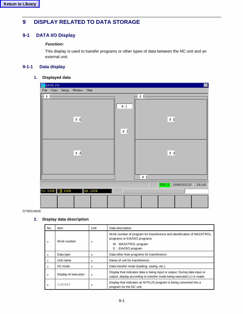
9-1
9 DISPLAY RELATED TO DATA STORAGE
9-1 DATA I/O Display
Function:
This display is used to transfer programs or other types of data between the NC unit and anexternal unit.
9-1-1 Data display
1. Displayed data
 $
 %
 (
 %
 '
 #
 &
 $
 #
D735S1062E
2. Display data description
No. Item Unit Data description
• Work number •
Work number of program for transference and identification of MAZATROLprograms or EIA/ISO programs
M: MAZATROL programE : EIA/ISO program
• Data type • Data other than programs for transference
• Unit name • Name of unit for transference
• I/O mode • Data transfer mode (loading, saving, etc.)
• Display of execution •Display that indicates data is being input or output. During data input oroutput, display according to transfer mode being executed (• ) is made.
• CONVERT •Display that indicates an M PLUS program is being converted into aprogram for the NC unit.
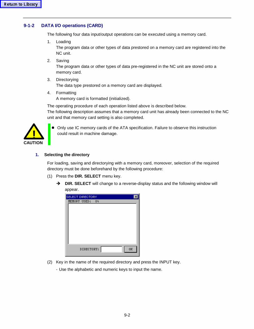
9-2
9-1-2 DATA I/O operations (CARD)
The following four data input/output operations can be executed using a memory card.
1. LoadingThe program data or other types of data prestored on a memory card are registered into theNC unit.
2. SavingThe program data or other types of data pre-registered in the NC unit are stored onto amemory card.
3. DirectoryingThe data type prestored on a memory card are displayed.
4. FormattingA memory card is formatted (initialized).
The operating procedure of each operation listed above is described below.The following description assumes that a memory card unit has already been connected to the NCunit and that memory card setting is also completed.
!CAUTION
z Only use IC memory cards of the ATA specification. Failure to observe this instructioncould result in machine damage.
1. Selecting the di rectory
For loading, saving and directorying with a memory card, moreover, selection of the requireddirectory must be done beforehand by the following procedure:
(1) Press the DIR. SELECT menu key.
Î DIR. SELECT will change to a reverse-display status and the following window willappear.
(2) Key in the name of the required directory and press the INPUT key.
- Use the alphabetic and numeric keys to input the name.
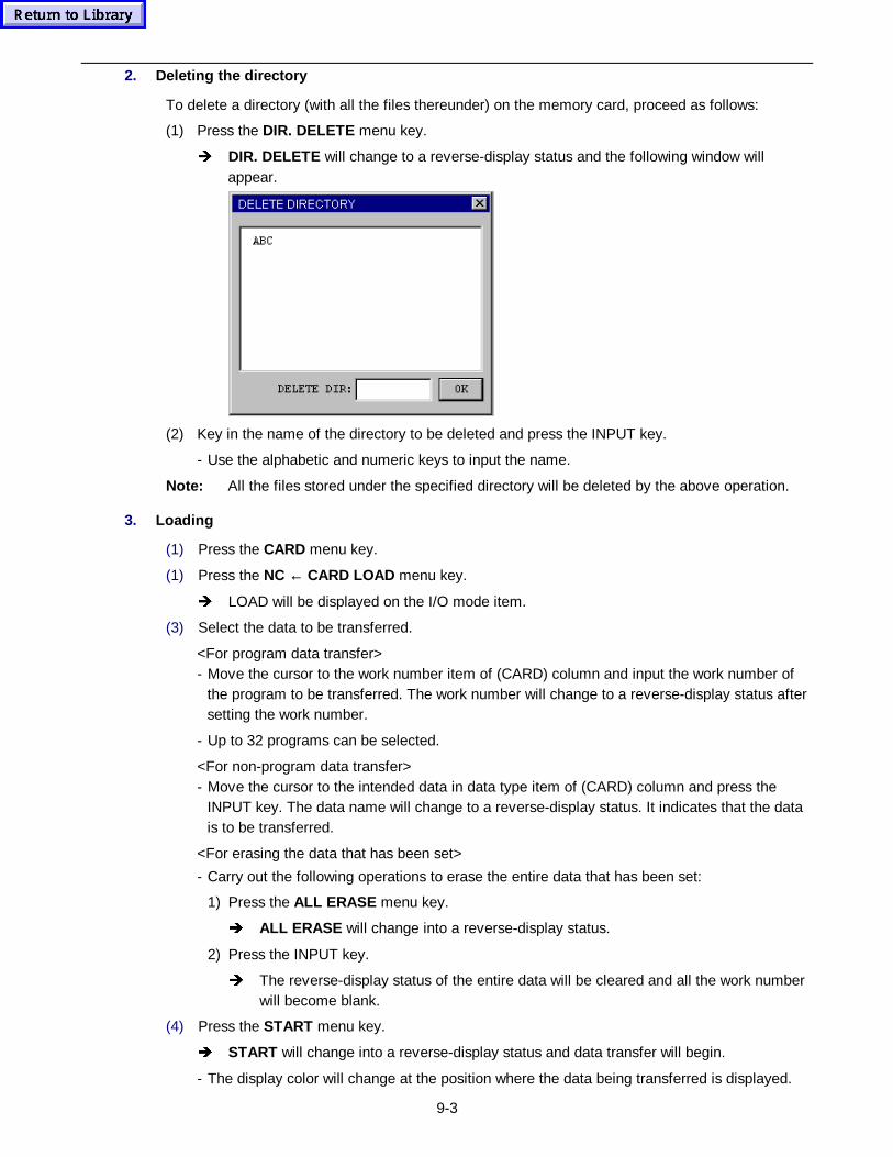
9-3
2. Deleting the di rectory
To delete a directory (with all the files thereunder) on the memory card, proceed as follows:
(1) Press the DIR. DELETE menu key.
Î DIR. DELETE will change to a reverse-display status and the following window willappear.
(2) Key in the name of the directory to be deleted and press the INPUT key.
- Use the alphabetic and numeric keys to input the name.
Note: All the files stored under the specified directory will be deleted by the above operation.
3. Loading
(1) Press the CARD menu key.
(1) Press the NC ← CARD LOAD menu key.
Î LOAD will be displayed on the I/O mode item.
(3) Select the data to be transferred.
<For program data transfer>- Move the cursor to the work number item of (CARD) column and input the work number of
the program to be transferred. The work number will change to a reverse-display status aftersetting the work number.
- Up to 32 programs can be selected.
<For non-program data transfer>- Move the cursor to the intended data in data type item of (CARD) column and press the
INPUT key. The data name will change to a reverse-display status. It indicates that the datais to be transferred.
<For erasing the data that has been set>
- Carry out the following operations to erase the entire data that has been set:
1) Press the ALL ERASE menu key.
Î ALL ERASE will change into a reverse-display status.
2) Press the INPUT key.
Î The reverse-display status of the entire data will be cleared and all the work numberwill become blank.
(4) Press the START menu key.
Î START will change into a reverse-display status and data transfer will begin.
- The display color will change at the position where the data being transferred is displayed.
9-4
- The highlighted-display status of the data that has been transferred will be cleared. Thesame data will be displayed in the (NC) column.
- After data transfer, the reverse-display status of START will be cleared.
Note 1: You can select using a parameter whether loading of a program whose work number isthe same as that of a program pre-registered within the NC unit, is to be enabled. Forfurther details of parameters, see the Parameter List.To enable such a program for which the loading operation is not available by parametersetting, to be loaded, the work number of the related pre-registered program must bechanged prior to loading.
Note 2: A listing window for the work numbers of all programs registered previously in the NC unitcan be displayed by pressing the PROGRAM FILE menu key. While the window remainson the display, the display status of the PROGRAM FILE menu reverses.Pressing the PROGRAM FILE menu key once again clears the reverse-display status ofthe menu item and closes the window.
Note 3: Data transfer will be continued even if the existing display is changed over to anotherdisplay during the data transfer process. However, the data being transferred cannot beoverridden.This also applies when a transfer mode other than LOAD has been selected.
Note 4: Data transfer will halt if the reverse-display status is cleared by pressing the STARTmenu key during the data transfer process. Data transfer cannot be restarted from theposition in which the transfer process has halted.This also applies when a transfer mode other than LOAD has been selected.
4. Saving
(1) Press the CARD menu key.
(1) Press the NC → CARD SAVE menu key.
Î SAVE will be displayed on the I/O mode item.
(3) Select the data to be transferred.
- The data input procedure is the same as that of LOAD. Input the data in the (NC) column.(See procedural step (3) of “3. Loading”.)
(4) Press the START menu key.
Î START will change to a reverse-display status and data transfer will begin.
- The display color will change at the position where the data being transferred is displayed.
- The data that has been transferred will change to a normal display status and the same datawill be displayed in the (CARD) column.
- After data transfer, the reverse-display status of START will be cleared.
9-5
5. Directorying
(1) Press the CARD menu key.
(2) Press the CARD CONTENT menu key.
Î DIR will be displayed on the I/O data item.
(3) Press the START menu key.
Î START will change into a reverse-display status, and what type of data is stored on thememory card will be displayed in the (CARD) column on the display.
- If program data is stored on the external media, the corresponding work number will bedisplayed on the work number item.
- If non-program data is stored on the external media, the corresponding item will bedisplayed in a reverse-display status.
- After entire data display is completed, the reverse-display status of START will be cleared.
6. Formatting
(1) Press the CARD menu key.
(2) Press the CARD FORMAT menu key.
Î FORMAT will be displayed on the I/O mode item.
(3) Key in “–9999” and press the INPUT key.
(4) Press the START menu key.
Î START will change into a reverse-display status and initialization will begin.
- Upon completion of the initialization, the reverse-display status of START will be cleared.
7. Selecting the HDD OPERATION PROGRAM area
Use the following procedure to select the HDD OPERATION PROGRAM area, instead of theSTANDARD PROGRAM area, for data input/output operations with an IC memory card:
(1) Press the HD AREA menu key.
Î HD AREA will change into a reverse-display status.
- The HDD OPERATION PROGRAM area will remain selected for the I/O operations with theIC memory card until the reverse display of HD AREA is cleared by pressing again the samemenu key.
9-6
9-1-3 DATA I/O operations (CMT)
The following four data input/output operations can be executed using a cassette tape or amicrodisk.
1. LoadingThe program data or other types of data prestored on a cassette tape (CMT) or a microdiskare registered into the NC unit.
2. SavingThe program data or other types of data pre-registered in the NC unit are stored onto acassette tape or a microdisk.
3. ComparingThe comparison is made between the data prestored on a cassette tape or a microdisk andthe data pre-registered in the NC unit.
4. DirectoryingThe data type prestored on a cassette tape or a microdisk are displayed.
The operating procedure of each operation listed above is described below.The following description assumes that a cassette tape deck or a MAZAK microdisk unit hasalready been connected to the NC unit and that cassette tape or microdisk setting is alsocompleted.
1. Loading
(1) Press the CMT I/O menu key.
(2) Press the LOAD NC ← CMT menu key.
Î LOAD will be displayed on the I/O mode item.
(3) Select the data to be transferred.
<For program data transfer>- Move the cursor to the work number item of (CMT) column and input the work number of the
program to be transferred. The work number will change to a reverse-display status aftersetting the work number.
- Up to 32 programs can be selected.
<For non-program data transfer>- Move the cursor to the intended data in data type item of (CMT) column and press the
INPUT key. The data name will change to a reverse-display status. It indicates that the datais to be transferred.
<For erasing the data that has been set>- Move the cursor to the data to be erased and press the data cancellation key. When the data
to be erased is a program, then the work number will become blank and the reverse-displaystatus will be cleared. In case of non-program data, the reverse-display status will becleared.
- Carry out the following operations to erase the entire data that has been set:
1) Press the ALL ERASE menu key.
Î ALL ERASE will change into a reverse-display status.
2) Press the INPUT key.
Î The reverse-display status of the entire data will be cleared and all the work numberwill become blank.
9-7
(4) Press the START menu key.
Î START will change into a reverse-display status and data transfer will begin.
- The display color will change at the position where the data being transferred is displayed.
- The highlighted-display status of the data that has been transferred will be cleared. Thesame data will be displayed in the (NC) column.
- After data transfer, the reverse-display status of START will be cleared.
Note 1: You can select using a parameter whether loading of a program whose work number isthe same as that of a program pre-registered within the NC unit, is to be enabled. Forfurther details of parameters, see the Parameter List.To enable such a program for which the loading operation is not available by parametersetting, to be loaded, the work number of the related pre-registered program must bechanged prior to loading.
Note 2: A listing window for the work numbers of all programs registered previously in the NC unitcan be displayed by pressing the PROGRAM FILE menu key. While the window remainson the display, the display status of the PROGRAM FILE menu reverses.Pressing the PROGRAM FILE menu key once again clears the reverse-display status ofthe menu item and closes the window.
Note 3: It is possible to load a program that has been created using the MAZATROL M PLUS (MPLUS program). In that case, the M PLUS program will be automatically converted into aprogram used for the NC unit of the machine. It is not possible, however, to load anyother types of data than programs even if they have been stored in the M PLUS.While the NC unit is reading in an M PLUS program, the message CONVERT will bedisplayed at the lower right corner of the display.
Note 4: Data transfer will be continued even if the existing display is changed over to anotherdisplay during the data transfer process. However, the data being transferred cannot beoverridden.This also applies when a transfer mode other than LOAD has been selected.
Note 5: Data transfer will halt if the reverse-display status is cleared by pressing the STARTmenu key during the data transfer process. Data transfer cannot be restarted from theposition in which the transfer process has halted.This also applies when a transfer mode other than LOAD has been selected.
Note 6: If data saving is interrupted, then although all previously set items will have their displaystatus reversed for the next directory, only data that has been transferred down tointerruption will have actually been saved.
2. Saving
(1) Press the CMT I/O menu key.
(2) Press the SAVE NC → CMT menu key.
Î SAVE will be displayed on the I/O mode item.
(3) Select the data to be transferred.
- The data input procedure is the same as that of LOAD. Input the data in the (NC) column.(See procedural step (3) of “1. Loading”.)
9-8
(4) Press the START menu key.
Î START will change to a reverse-display status and data transfer will begin.
- The display color will change to purple at the position where the data being transferred isdisplayed.
- The data that has been transferred will change to a normal display status and the same datawill be displayed in the (CMT) column.
- After data transfer, the reverse-display status of START will be cleared.
Note 1: When saving the entire NC data onto a microdisk, divide the storage area of themicrodisk into two segments, not into six segments. Division into six segments may resultin the lack of capacity.
Note 2: The PAGE SAVE menu item will be displayed if the display status of the PROGRAMFILE menu item is reversed by pressing the PROGRAM FILE menu key during thesaving transfer mode.
Note 3: Pressing the PAGE SAVE menu key during data setting allows all work numbersdisplayed in the work number listing window to be automatically set.If the PAGE SAVE menu key is pressed during data input/output, alarm 422 MEMORYPROTECT (I/O BUSY) will be displayed. This alarm will also be displayed if theCOMPARE transfer mode is selected.
3. Comparing
(1) Press the CMT I/O menu key.
(2) Press the COMPARE NC = CMT menu key.
Î COMPARE will be displayed on the I/O mode item.
(3) Select the data to be compared with data pre-registered within the NC unit.
- The data input procedure is the same as that of “1. Loading”. Input the data in the (NC)column. (See procedural step (3) of “1. Loading”.)
(4) Press the START menu key.
Î START will change into a reverse-display status and data comparing will begin.
- The display color will change to purple at the position where the data being compared isdisplayed.
- The data that has been compared will change to a normal display status and the same datawill be displayed in the (CMT) column.
- If the reverse-display status of START is cleared without displaying an alarm message, thenthis indicates that the entire data you have selected agrees with data pre-registered withinthe NC unit.
- If disparities exist in the data being compared, an alarm message 511 PROGRAM DATANOT SAME will be displayed and the comparison process will be aborted.This state indicates that data being displayed in purple does not agree with data pre-registered within the NC unit.
9-9
4. Directorying
(1) Press the CMT I/O menu key.
(2) Press the CMT CONTENTS menu key.
Î DIR will be displayed on the I/O data item.
(3) Press the START menu key.
Î START will change into a reverse-display status, and what type of data is stored on thecassette tape (CMT) or the microdisk will be displayed in the (CMT) column on thedisplay.
- If program data is stored on the external media, the corresponding work number will bedisplayed on the work number item.
- If non-program data is stored on the external media, the corresponding item will bedisplayed in a reverse-display status.
- After entire data display is completed, the reverse-display status of START will be cleared.
Note: Executing a Directorying operation prior to Loading or Comparing operations enablesdata selection time to be saved.
Example 1: Do the following to load the entire data that is stored on a cassette tape ora microdisk:
(1) Call the stored data out on the display by carrying out a directorying operation.
(2) Press the LOAD NC ← CMT menu key.
(3) Press the START menu key.
Example 2: Do the following to load part of the data stored on a cassette tape or amicrodisk:
(1) Call the stored data out on the display by carrying out a directorying operation.
(2) Press the LOAD NC ← CMT menu key.
(3) Set the cursor on the data not to be loaded and press the data cancellation key.Or set 0 for program not to be loaded.
(4) Press the START menu key.
5. Setting of communications p arameters
A. Setting of p arameters
Parameters for data transfer (baud rate, etc.) can be set on this display by the following procedure:
(1) Press the PARAM. menu key.
Î PARAM. will change to a reverse-display status and parameters for data transfer will bepresented in a window.
(2) Set the parameters as required.
- Refer to the Parameter List for details of the parameters.
(3) Press the INPUT key or click OK in the window.
Î The reverse-display status of PARAM. will be cleared and the window will disappear.
9-10
B. Setting of detailed p arameters
(1) Press the PARAM. DETAIL menu key.
Î PARAM. DETAIL will change to a reverse-display status and parameters for data transferwill be presented in a window.
(2) Set the parameters as required.
- Refer to the Parameter List for details of the parameters.
(3) Press the INPUT key or click OK in the window.
Î The reverse-display status of PARAM. DETAIL will be cleared and the window willdisappear.
9-1-4 DATA I/O operations (TAPE)
The following six data input/output operations can be executed using a paper tape or a microdisk.
1. LoadingA program or non-program data of all those prestored on a paper tape or a microdisk isregistered in the NC unit.
2. All loadingAll programs and non-program data prestored on a paper tape or a microdisk are registered inthe NC unit.
3. PunchingA program or non-program data of all those pre-registered within the NC unit is stored on apaper tape or a microdisk.
4. All punchingAll programs and non-program data pre-registered within the NC unit are stored on a papertape or a microdisk.
5. ComparingA program or non-program data of all those prestored on a paper tape or a microdisk iscompared with a program or non-program data pre-registered within the NC unit.
6. All comparingAll programs and non-program data prestored on a paper tape or a microdisk are comparedwith the programs and non-program data pre-registered within the NC unit.
Note: All the data other than EIA/ISO programs are I/O-operated in the three-digit G-codeformat, the details of which are described in the Programming Manual (MAZATROL).
The operating procedure for the functions listed above is described below. The followingdescription assumes that a paper tape reader/puncher or a MAZAK microdisk unit has alreadybeen connected to the NC unit and that paper tape or microdisk setting is also completed.
1. Loading
(1) Press the TAPE I/O menu key.
(1) Press the LOAD NC ← TAPE menu key.
Î LOAD will be displayed on the I/O mode item.
(3) Select the data to be transferred.
- Refer to procedural step (3) of “1. Loading” in Subsection 9-1-3.
(4) Press the START menu key.
Î START will change into a reverse-display status, and data transfer will begin.
9-11
- The display color will change to purple at the position in which the data being transferred isdisplayed.
- After data transfer, the reverse-display status of START will be cleared.
Note: The precautions described in Notes 1 , 2, 4 and 5 in “1. Loading” of 9-1-3 DATA I/Ooperat ions (CMT) are valid for this loading operation.
2. All loading
(1) Press the TAPE I/O menu key.
(1) Press the ALL LOAD NC ← TAPE menu key.
Î ALL LOAD will be displayed on the I/O mode item.
(3) Press the START menu key.
Î START will change into a reverse-display status, and data transfer will begin.
- After data transfer, the reverse-display status of the START will be cleared.
3. Punching
(1) Press the TAPE I/O menu key.
(2) Press the PUNCH NC → TAPE menu key.
Î PUNCH will be displayed on the I/O mode item.
(3) Select the data to be transferred.
- See the description of procedural step (3) of “1. Loading”. Set data in the (NC) column.
(4) Press the START menu key.
Î START will change into a reverse-display status, and the tape puncher will startoperating.
- The display color will change to purple at the position in which the data being punched out isdisplayed.
- The name of the data that has been transferred will change to a normal display status andthe same data name is displayed in the (TAPE) column.
- After all the selected data have been punched on the paper tape, the reverse-display statusof START will be cleared.
4. All punching
(1) Press the TAPE I/O menu key.
(2) Press the ALL PUNCH NC →• TAPE menu key.
Î ALL PNC will be displayed on the I/O mode item.
(3) Press the START menu key.
Î START will change into a reverse-display status, and the tape puncher will startoperating.
- After all the pre-registered programs and other data have been punched on the paper tape,the reverse-display status of START will be cleared.
9-12
5. Comparing
(1) Press the TAPE I/O menu key.
(2) Press the COMPARE NC = TAPE menu key.
Î COMPARE will be displayed on the I/O mode item.
(3) Select the data to be compared.
- See the description of procedural step (3) of “1. Loading”.
(4) Press the START menu key.
Î START will change into a reverse-display status, and data comparison will begin.
- The display color will change to purple at the position in which the data being compared isdisplayed.
- The name of the data that has been compared will change to a normal display status and thesame data name will be displayed in the (NC) column.
- Clearing of the reverse-display status of START without an alarm message indicates thatthe contents of all the selected data agree with those of the pre-registered data.
- If disparities exist in the data being compared, an alarm message 511 PROGRAM DATANOT SAME will be displayed and comparison will be aborted.This indicates that the contents of the data displayed in purple do not agree with the contentsof the pre-registered counterpart.
6. All comparing
(1) Press the TAPE I/O menu key.
(2) Press the ALLCOMP NC = TAPE menu key.
Î ALL CMP will be displayed on the I/O mode item.
(3) Press the START menu key.
Î START will change into a reverse-display status, and data comparison will begin.
- Clearing of the reverse-display status of START without an alarm message indicates thatthe contents of all data stored on the paper tape agree with those of the data pre-registeredwithin the NC unit.
- If disparities exist in the data being compared, an alarm message 511 PROGRAM DATANOT SAME will be displayed and comparison will be aborted.
7. Program-name tape input/output
When a program is transferred using tape I/O function, the name of the program which is set onthe PROGRAM FILE display can be assigned to that program during transfer operation.
A. Transfer conditions
1. Input or output of program names is possible only if the program-name tape I/O function hasbeen made valid using bit 2 of parameter TAP26.See the Parameter List, for parameter details.
2. The following functions presented on the DATA I/O display (TAPE) can be used to transferprogram names to or from a tape.
- Loading- All loading- Punching
9-13
- All punching- Comparing- All comparing
B. Tape format
The name of the program transferred to or from a tape must be designated as follows:Set the control-out code “(” after the number with O, then set the program name and the control-incode “)”, in that order.
Example: O00001234 (COMMENT1234)
•Program name
C. Notes
1. Only the codes listed in the ASCII codes list can be used as program names.If an ASCII code other than 20, 2D, 2E, 30 to 39, or 41 to 5A is entered as the program name,the ASCII code will be converted into a space code (&20) and registered in the internalmemory of the NC unit.
2. The maximum number of name characters which can be stored into the NC internal memoryduring the program-name loading operation is 48. If, therefore, the name to be loaded consistsof 49 characters or more, all those excess characters will be ignored.
8. Setting of communications p arameters
A. Setting of p arameters
Parameters for data transfer (baud rate, etc.) can be set on this display by the following procedure:
(1) Press the PARAM. menu key.
Î PARAM. will change to a reverse-display status and parameters for data transfer will bepresented in a window.
(2) Set the parameters as required.
- Refer to the Parameter List for details of the parameters.
(3) Press the INPUT key or click OK in the window.
Î The reverse-display status of PARAM. will be cleared and the window will disappear.
B. Setting of detailed p arameters
(1) Press the PARAM. DETAIL menu key.
Î PARAM. DETAIL will change to a reverse-display status and parameters for data transferwill be presented in a window.
(2) Set the parameters as required.
- Refer to the Parameter List for details of the parameters.
(3) Press the INPUT key or click OK in the window.
Î The reverse-display status of PARAM. DETAIL will be cleared and the window willdisappear.
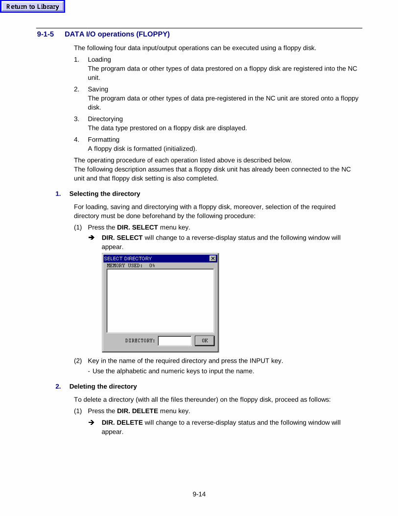
9-14
9-1-5 DATA I/O operations (FLOPPY)
The following four data input/output operations can be executed using a floppy disk.
1. LoadingThe program data or other types of data prestored on a floppy disk are registered into the NCunit.
2. SavingThe program data or other types of data pre-registered in the NC unit are stored onto a floppydisk.
3. DirectoryingThe data type prestored on a floppy disk are displayed.
4. FormattingA floppy disk is formatted (initialized).
The operating procedure of each operation listed above is described below.The following description assumes that a floppy disk unit has already been connected to the NCunit and that floppy disk setting is also completed.
1. Selecting the di rectory
For loading, saving and directorying with a floppy disk, moreover, selection of the requireddirectory must be done beforehand by the following procedure:
(1) Press the DIR. SELECT menu key.
Î DIR. SELECT will change to a reverse-display status and the following window willappear.
(2) Key in the name of the required directory and press the INPUT key.
- Use the alphabetic and numeric keys to input the name.
2. Deleting the di rectory
To delete a directory (with all the files thereunder) on the floppy disk, proceed as follows:
(1) Press the DIR. DELETE menu key.
Î DIR. DELETE will change to a reverse-display status and the following window willappear.
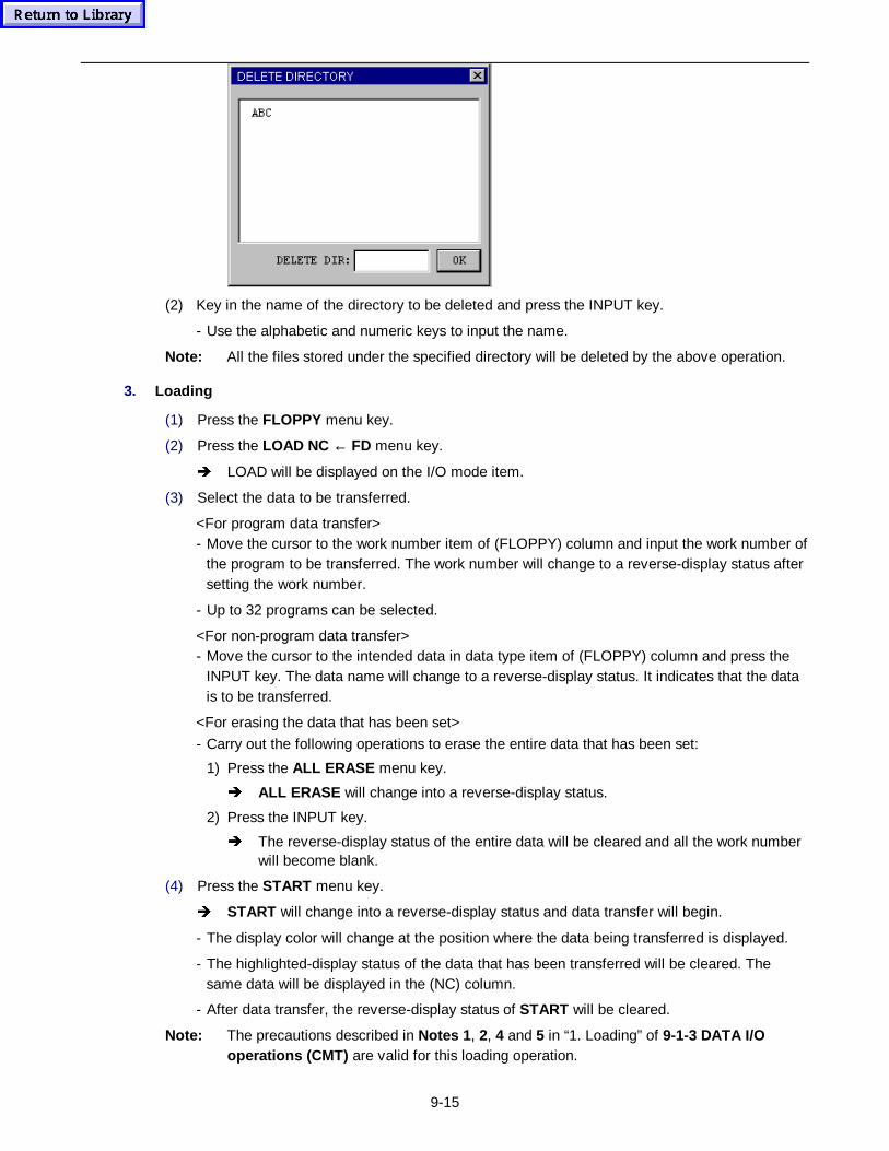
9-15
(2) Key in the name of the directory to be deleted and press the INPUT key.
- Use the alphabetic and numeric keys to input the name.
Note: All the files stored under the specified directory will be deleted by the above operation.
3. Loading
(1) Press the FLOPPY menu key.
(2) Press the LOAD NC ← FD menu key.
Î LOAD will be displayed on the I/O mode item.
(3) Select the data to be transferred.
<For program data transfer>- Move the cursor to the work number item of (FLOPPY) column and input the work number of
the program to be transferred. The work number will change to a reverse-display status aftersetting the work number.
- Up to 32 programs can be selected.
<For non-program data transfer>- Move the cursor to the intended data in data type item of (FLOPPY) column and press the
INPUT key. The data name will change to a reverse-display status. It indicates that the datais to be transferred.
<For erasing the data that has been set>
- Carry out the following operations to erase the entire data that has been set:
1) Press the ALL ERASE menu key.
Î ALL ERASE will change into a reverse-display status.
2) Press the INPUT key.
Î The reverse-display status of the entire data will be cleared and all the work numberwill become blank.
(4) Press the START menu key.
Î START will change into a reverse-display status and data transfer will begin.
- The display color will change at the position where the data being transferred is displayed.
- The highlighted-display status of the data that has been transferred will be cleared. Thesame data will be displayed in the (NC) column.
- After data transfer, the reverse-display status of START will be cleared.
Note: The precautions described in Notes 1 , 2, 4 and 5 in “1. Loading” of 9-1-3 DATA I/Ooperat ions (CMT) are valid for this loading operation.
9-16
4. Saving
(1) Press the FLOPPY menu key.
(2) Press the SAVE NC → FD menu key.
Î SAVE will be displayed on the I/O mode item.
(3) Select the data to be transferred.
- The data input procedure is the same as that of LOAD. Input the data in the (NC) column.(See procedural step (3) of “3. Loading”.)
(4) Press the START menu key.
Î START will change to a reverse-display status and data transfer will begin.
- The display color will change at the position where the data being transferred is displayed.
- The data that has been transferred will change to a normal display status and the same datawill be displayed in the (FLOPPY) column.
- After data transfer, the reverse-display status of START will be cleared.
5. Directorying
(1) Press the FLOPPY menu key.
(2) Press the CONTENTS FD menu key.
Î DIR will be displayed on the I/O data item.
(3) Press the START menu key.
Î START will change into a reverse-display status, and what type of data is stored on thefloppy disk will be displayed in the (FLOPPY) column on the display.
- If program data is stored on the external media, the corresponding work number will bedisplayed on the work number item.
- If non-program data is stored on the external media, the corresponding item will bedisplayed in a reverse-display status.
- After entire data display is completed, the reverse-display status of START will be cleared.
6. Formatting
(1) Press the FLOPPY menu key.
(2) Press the FORMAT FD menu key.
Î FORMAT will be displayed on the I/O mode item.
(3) Key in “–9999” and press the INPUT key.
(4) Press the START menu key.
Î START will change into a reverse-display status and initialization will begin.
- After initialization, the reverse-display status of START will be cleared.
Note 1: Only double-sided high-density (2HD) floppy disks can be used.
Note 2: Formatting is executed at 1.44 MB.
9-1-6 DATA I/O operations (DNC)
The following two data input/output operations can be executed using a host CPU or other NC.
1. LoadingNon-program data or programs pre-registered within a host CPU or the NC unit of other
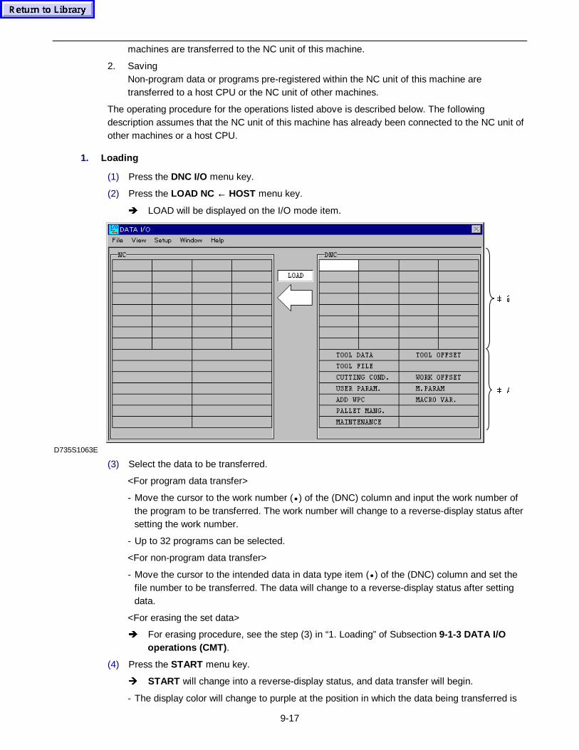
9-17
machines are transferred to the NC unit of this machine.
2. SavingNon-program data or programs pre-registered within the NC unit of this machine aretransferred to a host CPU or the NC unit of other machines.
The operating procedure for the operations listed above is described below. The followingdescription assumes that the NC unit of this machine has already been connected to the NC unit ofother machines or a host CPU.
1. Loading
(1) Press the DNC I/O menu key.
(2) Press the LOAD NC ← HOST menu key.
Î LOAD will be displayed on the I/O mode item.
 $
 #
D735S1063E
(3) Select the data to be transferred.
<For program data transfer>
- Move the cursor to the work number (• ) of the (DNC) column and input the work number ofthe program to be transferred. The work number will change to a reverse-display status aftersetting the work number.
- Up to 32 programs can be selected.
<For non-program data transfer>
- Move the cursor to the intended data in data type item (• ) of the (DNC) column and set thefile number to be transferred. The data will change to a reverse-display status after settingdata.
<For erasing the set data>
Î For erasing procedure, see the step (3) in “1. Loading” of Subsection 9-1-3 DATA I/Ooperat ions (CMT) .
(4) Press the START menu key.
Î START will change into a reverse-display status, and data transfer will begin.
- The display color will change to purple at the position in which the data being transferred is
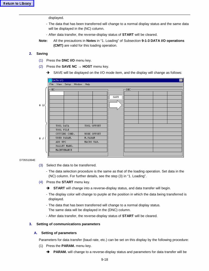
9-18
displayed.
- The data that has been transferred will change to a normal display status and the same datawill be displayed in the (NC) column.
- After data transfer, the reverse-display status of START will be cleared.
Note: All the precautions in Notes in “1. Loading” of Subsection 9-1-3 DATA I/O op erat ions(CMT) are valid for this loading operation.
2. Saving
(1) Press the DNC I/O menu key.
(2) Press the SAVE NC → HOST menu key.
Î SAVE will be displayed on the I/O mode item, and the display will change as follows:
 $
 #
D735S1064E
(3) Select the data to be transferred.
- The data selection procedure is the same as that of the loading operation. Set data in the(NC) column. For further details, see the step (3) in “1. Loading”.
(4) Press the START menu key.
Î START will change into a reverse-display status, and data transfer will begin.
- The display color will change to purple at the position in which the data being transferred isdisplayed.
- The data that has been transferred will change to a normal display status.The same data will be displayed in the (DNC) column.
- After data transfer, the reverse-display status of START will be cleared.
3. Setting of communications p arameters
A. Setting of p arameters
Parameters for data transfer (baud rate, etc.) can be set on this display by the following procedure:
(1) Press the PARAM. menu key.
Î PARAM. will change to a reverse-display status and parameters for data transfer will be
9-19
presented in a window.
(2) Set the parameters as required.
- Refer to the Parameter List for details of the parameters.
(3) Press the INPUT key or click OK in the window.
The reverse-display status of PARAM. will be cleared and the window will disappear.
B. Setting of detailed p arameters
(1) Press the PARAM. DETAIL menu key.
Î PARAM. DETAIL will change to a reverse-display status and parameters for data transferwill be presented in a window.
(2) Set the parameters as required.
- Refer to the Parameter List for details of the parameters.
(3) Press the INPUT key or click OK in the window.
Î The reverse-display status of PARAM. DETAIL will be cleared and the window willdisappear.
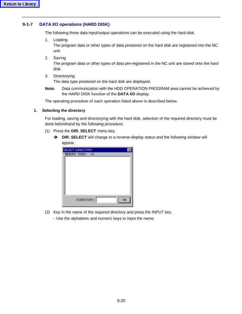
9-20
9-1-7 DATA I/O operations (HARD DISK)
The following three data input/output operations can be executed using the hard disk.
1. LoadingThe program data or other types of data prestored on the hard disk are registered into the NCunit.
2. SavingThe program data or other types of data pre-registered in the NC unit are stored onto the harddisk.
3. DirectoryingThe data type prestored on the hard disk are displayed.
Note: Data communication with the HDD OPERATION PROGRAM area cannot be achieved bythe HARD DISK function of the DATA I/O display.
The operating procedure of each operation listed above is described below.
1. Selecting the di rectory
For loading, saving and directorying with the hard disk, selection of the required directory must bedone beforehand by the following procedure:
(1) Press the DIR. SELECT menu key.
Î DIR. SELECT will change to a reverse-display status and the following window willappear.
(2) Key in the name of the required directory and press the INPUT key.
- Use the alphabetic and numeric keys to input the name.
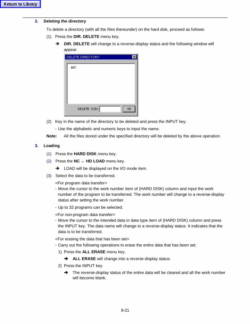
9-21
2. Deleting the di rectory
To delete a directory (with all the files thereunder) on the hard disk, proceed as follows:
(1) Press the DIR. DELETE menu key.
Î DIR. DELETE will change to a reverse-display status and the following window willappear.
(2) Key in the name of the directory to be deleted and press the INPUT key.
- Use the alphabetic and numeric keys to input the name.
Note: All the files stored under the specified directory will be deleted by the above operation.
3. Loading
(1) Press the HARD DISK menu key.
(2) Press the NC ← HD LOAD menu key.
Î LOAD will be displayed on the I/O mode item.
(3) Select the data to be transferred.
<For program data transfer>- Move the cursor to the work number item of (HARD DISK) column and input the work
number of the program to be transferred. The work number will change to a reverse-displaystatus after setting the work number.
- Up to 32 programs can be selected.
<For non-program data transfer>- Move the cursor to the intended data in data type item of (HARD DISK) column and press
the INPUT key. The data name will change to a reverse-display status. It indicates that thedata is to be transferred.
<For erasing the data that has been set>
- Carry out the following operations to erase the entire data that has been set:
1) Press the ALL ERASE menu key.
Î ALL ERASE will change into a reverse-display status.
2) Press the INPUT key.
Î The reverse-display status of the entire data will be cleared and all the work numberwill become blank.
9-22
(4) Press the START menu key.
Î START will change into a reverse-display status and data transfer will begin.
- The display color will change at the position where the data being transferred is displayed.
- The highlighted-display status of the data that has been transferred will be cleared. Thesame data will be displayed in the (NC) column.
- After data transfer, the reverse-display status of START will be cleared.
Note: The precautions described in Notes 1 , 2, 4 and 5 in “1. Loading” of 9-1-3 DATA I/Ooperat ions (CMT) are valid for this loading operation.
4. Saving
(1) Press the HARD DISK menu key.
(2) Press the NC → HD SAVE menu key.
Î SAVE will be displayed on the I/O mode item.
(3) Select the data to be transferred.
- The data input procedure is the same as that of LOAD. Input the data in the (NC) column.(See procedural step (3) of “3. Loading”.)
(4) Press the START menu key.
Î START will change to a reverse-display status and data transfer will begin.
- The display color will change at the position where the data being transferred is displayed.
- The data that has been transferred will change to a normal display status and the same datawill be displayed in the (HARD DISK) column.
- After data transfer, the reverse-display status of START will be cleared.
5. Directorying
(1) Press the HARD DISK menu key.
(2) Press the HD CONTENT menu key.
Î DIR will be displayed on the I/O data item.
(3) Press the START menu key.
Î START will change into a reverse-display status, and what type of data is stored on thehard disk will be displayed in the (HARD DISK) column on the display.
- If program data is stored on the external media, the corresponding work number will bedisplayed on the work number item.
- If non-program data is stored on the external media, the corresponding item will bedisplayed in a reverse-display status.
- After entire data display is completed, the reverse-display status of START will be cleared.
9-23
9-2 Program Transfer from the Host PC to the Memory Card
9-2-1 Outline
This section explains how to transfer machining programs, under an Ethernet-based networkenvironment, from the host PC to the memory card inserted into the front slot on the M640operating panel.
Use of the method explained below eliminates the need for the host PC to have any memory cardhandling equipment, and only the related data input/output functions of the M640 are needed towrite program files onto the memory card.
The examples shown in this section assume the following environment where the host PC and theM640 are already connected to the network:
- Host PC ............................A personal computer having installed Microsoft Windows95/98 orMicrosoft Windows NT4.0,
- Network connection...........Ethernet connection based on Windows functions,
- Network protocol ...............Microsoft network and Microsoft network sharing services.
Note: The host PC can use an operating system (OS) other than the above or the host PC itselfmay be a workstation if the program files can surely be transferred to the folder within thehard disk (HD) of the M640. See the OS-accompanying manuals for detailed informationabout transferring program files.
The procedure for transferring programs is outlined below.
(1) Modifying the HD-operating program storage folder of the M640 into a sharable folder.
(2) Copying program files from the host PC into the HD-operating program storage folder of theM640.
(3) Selecting the DATA I/O display on the M640 and copying program files from the HD into thememory card.
9-2-2 Detailed description
1. Modifying the HD-op erat ing prog ram storage f older into a sharable folder
The HD-operating program storage folder within the HD of the M640 can be made readable andwritable from another Windows personal computer present on the network by modifying theattributes of that folder. This task is called folder sharing, and the corresponding folder is referredto as a sharable folder.
The procedure is as follows:
(1) Start the Windows Explorer.
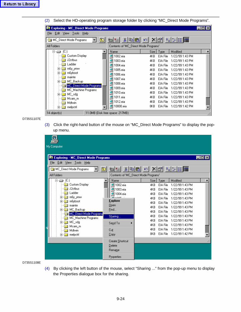
9-24
(2) Select the HD-operating program storage folder by clicking “MC_Direct Mode Programs”.
D735S1107E
(3) Click the right-hand button of the mouse on “MC_Direct Mode Programs” to display the pop-up menu.
D735S1108E
(4) By clicking the left button of the mouse, select “Sharing ...” from the pop-up menu to displaythe Properties dialogue box for the sharing.
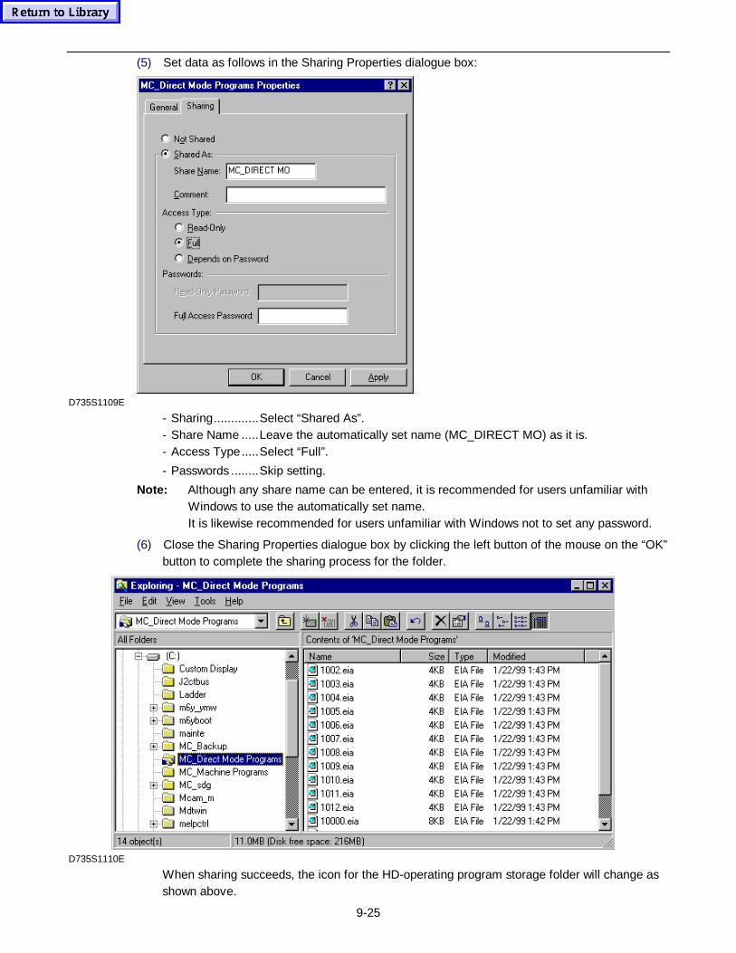
9-25
(5) Set data as follows in the Sharing Properties dialogue box:
D735S1109E
- Sharing.............Select “Shared As”.- Share Name .....Leave the automatically set name (MC_DIRECT MO) as it is.- Access Type.....Select “Full”.
- Passwords ........Skip setting.
Note: Although any share name can be entered, it is recommended for users unfamiliar withWindows to use the automatically set name.It is likewise recommended for users unfamiliar with Windows not to set any password.
(6) Close the Sharing Properties dialogue box by clicking the left button of the mouse on the “OK”button to complete the sharing process for the folder.
D735S1110E
When sharing succeeds, the icon for the HD-operating program storage folder will change asshown above.
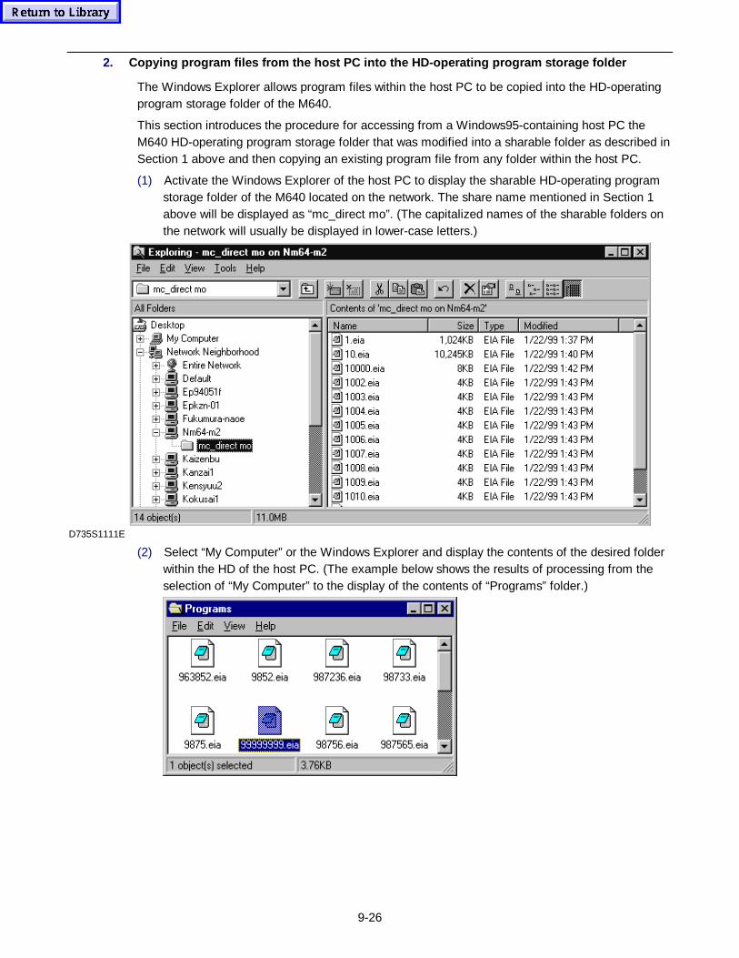
9-26
2. Copying prog ram files from the host PC into the HD-operat ing prog ram storage f older
The Windows Explorer allows program files within the host PC to be copied into the HD-operatingprogram storage folder of the M640.
This section introduces the procedure for accessing from a Windows95-containing host PC theM640 HD-operating program storage folder that was modified into a sharable folder as described inSection 1 above and then copying an existing program file from any folder within the host PC.
(1) Activate the Windows Explorer of the host PC to display the sharable HD-operating programstorage folder of the M640 located on the network. The share name mentioned in Section 1above will be displayed as “mc_direct mo”. (The capitalized names of the sharable folders onthe network will usually be displayed in lower-case letters.)
D735S1111E
(2) Select “My Computer” or the Windows Explorer and display the contents of the desired folderwithin the HD of the host PC. (The example below shows the results of processing from theselection of “My Computer” to the display of the contents of “Programs” folder.)
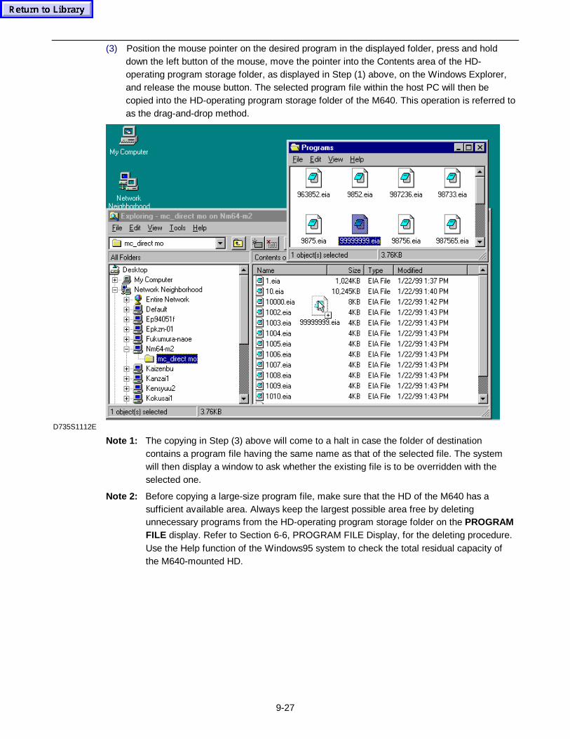
9-27
(3) Position the mouse pointer on the desired program in the displayed folder, press and holddown the left button of the mouse, move the pointer into the Contents area of the HD-operating program storage folder, as displayed in Step (1) above, on the Windows Explorer,and release the mouse button. The selected program file within the host PC will then becopied into the HD-operating program storage folder of the M640. This operation is referred toas the drag-and-drop method.
D735S1112E
Note 1: The copying in Step (3) above will come to a halt in case the folder of destinationcontains a program file having the same name as that of the selected file. The systemwill then display a window to ask whether the existing file is to be overridden with theselected one.
Note 2: Before copying a large-size program file, make sure that the HD of the M640 has asufficient available area. Always keep the largest possible area free by deletingunnecessary programs from the HD-operating program storage folder on the PROGRAMFILE display. Refer to Section 6-6, PROGRAM FILE Display, for the deleting procedure.Use the Help function of the Windows95 system to check the total residual capacity ofthe M640-mounted HD.
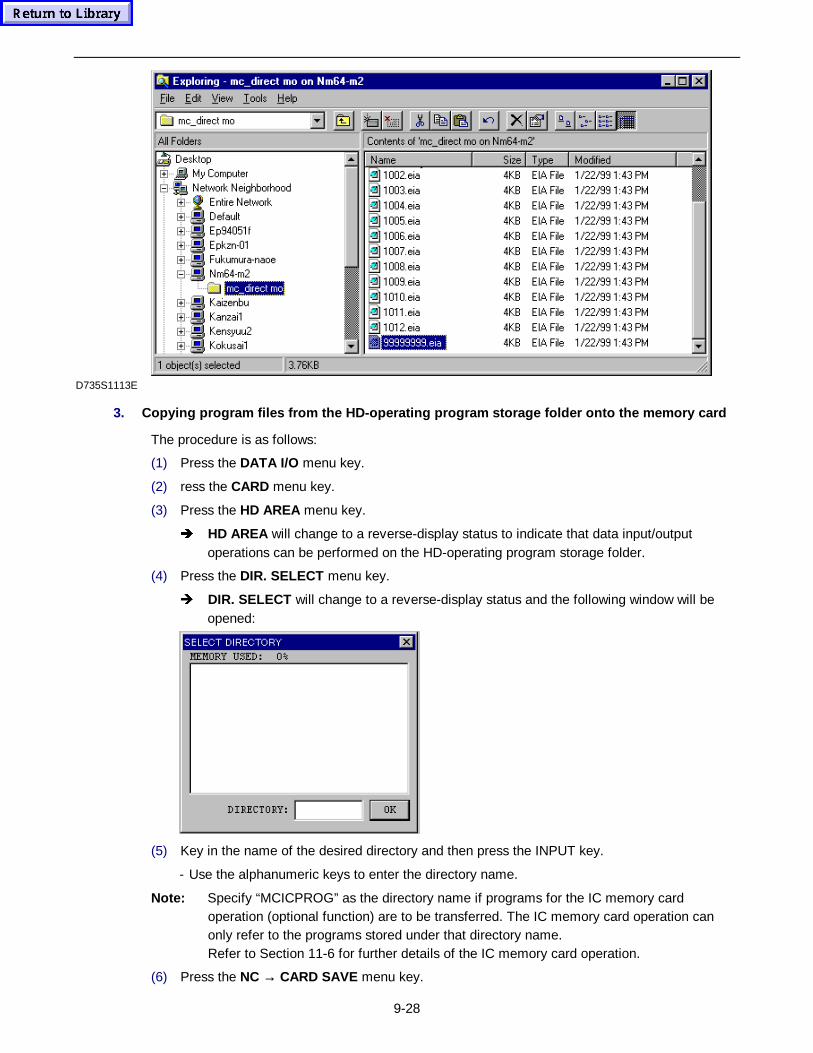
9-28
D735S1113E
3. Copying prog ram files from the HD-operat ing prog ram storage f older onto the memory card
The procedure is as follows:
(1) Press the DATA I/O menu key.
(2) ress the CARD menu key.
(3) Press the HD AREA menu key.
Î HD AREA will change to a reverse-display status to indicate that data input/outputoperations can be performed on the HD-operating program storage folder.
(4) Press the DIR. SELECT menu key.
Î DIR. SELECT will change to a reverse-display status and the following window will beopened:
(5) Key in the name of the desired directory and then press the INPUT key.
- Use the alphanumeric keys to enter the directory name.
Note: Specify “MCICPROG” as the directory name if programs for the IC memory cardoperation (optional function) are to be transferred. The IC memory card operation canonly refer to the programs stored under that directory name.Refer to Section 11-6 for further details of the IC memory card operation.
(6) Press the NC → CARD SAVE menu key.

9-29
(7) Specify the program(s) to be transferred.
(8) Press the START menu key.
Î START will change to a reverse-display status to indicate that transfer of the programhas been started.
- The reverse-display status of START will be cleared upon completion of the programtransfer.
Note: Before copying a program onto the IC memory card, make sure that the IC memory cardhas a sufficient available area. Take great care when copying a program of a largecapacity, in particular. If the size of the desired program file within the HD-operatingprogram storage folder is larger than the capacity of the IC memory card to be used, it isnot possible to transfer that program file.

9-30
- NOTE -

10-1
10 DISPLAYS RELATED TO DIAGNOSIS
The NC unit provides the following diagnostic displays and windows:
1. DIAGNOSIS (USER) display [ALARM, ALARM HISTORY, PLC SIGNAL]
2. MAINTENANCE CHECK display
3. PLC display
4. RUNNING CONTROL display
5. DIAGNOSIS (MAKER) display [VERSION, DIAGNOSIS MONITOR, OPTION, SERVOMONITOR*, SPINDLE MONITOR*, HARDWARE MONITOR*, LADDER MONITOR*]
6. DATA ERASE window
7. ACCUMULATED TIME window
Description of displays marked with an asterisk (*) is omitted because these displays are reservedfor YAMAZAKI MAZAK servicemen.
10-1 DIAGNOSIS (USER) – ALARM Display
Function:
- Displaying the number, details, etc. of alarms currently occuring
Remarks:
- Even if more than one alarm occurred, only one of the alarm messages will appear on otherdisplays. Selection of this display, however, gives you further detailed information about allalarms whose causes have not been removed.
- Refer to the Alarm List for further details of alarms and their resetting methods.
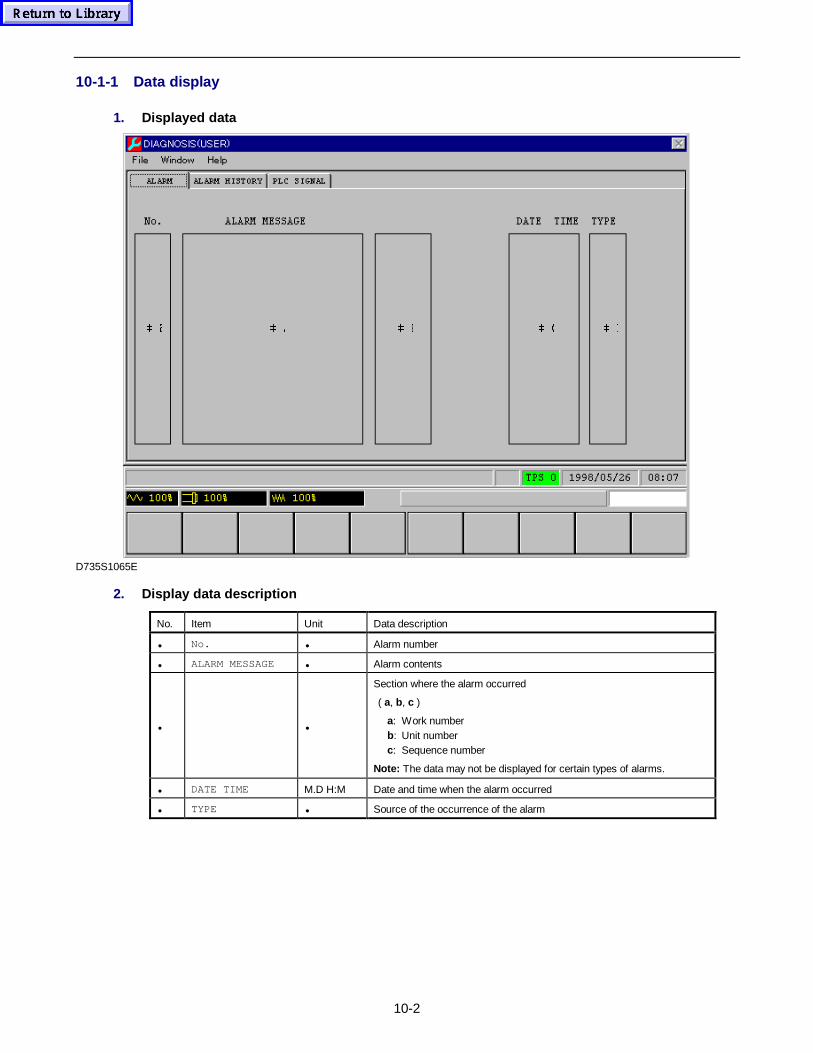
10-2
10-1-1 Data display
1. Displayed data
 ' & % $ #
D735S1065E
2. Display data description
No. Item Unit Data description
• No. • Alarm number
• ALARM MESSAGE • Alarm contents
• •
Section where the alarm occurred
( a, b, c )
a: Work numberb: Unit numberc: Sequence number
Note: The data may not be displayed for certain types of alarms.
• DATE TIME M.D H:M Date and time when the alarm occurred
• TYPE • Source of the occurrence of the alarm
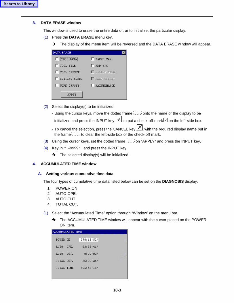
10-3
3. DATA ERASE window
This window is used to erase the entire data of, or to initialize, the particular display.
(1) Press the DATA ERASE menu key.
Î The display of the menu item will be reversed and the DATA ERASE window will appear.
(2) Select the display(s) to be initialized.
- Using the cursor keys, move the dotted frame onto the name of the display to be
initialized and press the INPUT key to put a check-off mark 9 on the left-side box.
- To cancel the selection, press the CANCEL key with the required display name put inthe frame to clear the left-side box of the check-off mark.
(3) Using the cursor keys, set the dotted frame on “APPLY” and press the INPUT key.
(4) Key in “ –9999” and press the INPUT key.
Î The selected display(s) will be initialized.
4. ACCUMULATED TIME window
A. Setting various cumulative time data
The four types of cumulative time data listed below can be set on the DIAGNOSIS display.
1. POWER ON2. AUTO OPE.3. AUTO CUT.4. TOTAL CUT.
(1) Select the “Accumulated Time” option through “Window” on the menu bar.
Î The ACCUMULATED TIME window will appear with the cursor placed on the POWERON item.
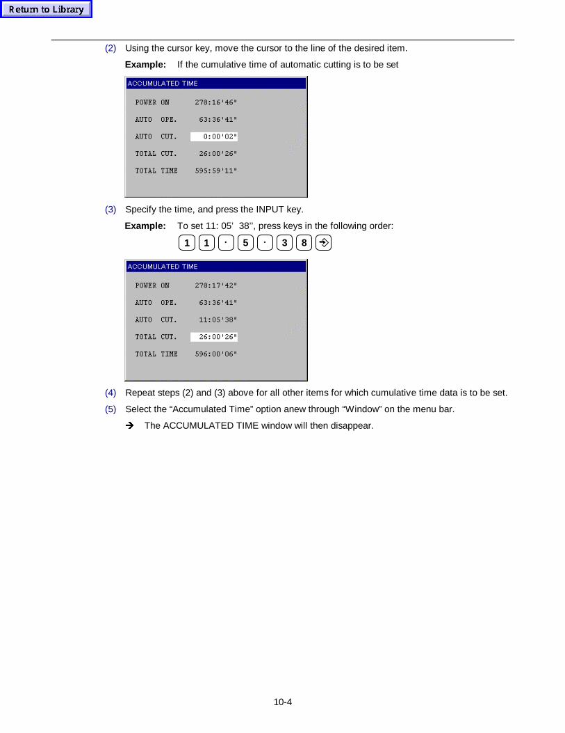
10-4
(2) Using the cursor key, move the cursor to the line of the desired item.
Example: If the cumulative time of automatic cutting is to be set
(3) Specify the time, and press the INPUT key.
Example: To set 11: 05’ 38’’, press keys in the following order:
1 1 • 5 • 3 8
(4) Repeat steps (2) and (3) above for all other items for which cumulative time data is to be set.
(5) Select the “Accumulated Time” option anew through “Window” on the menu bar.
Î The ACCUMULATED TIME window will then disappear.
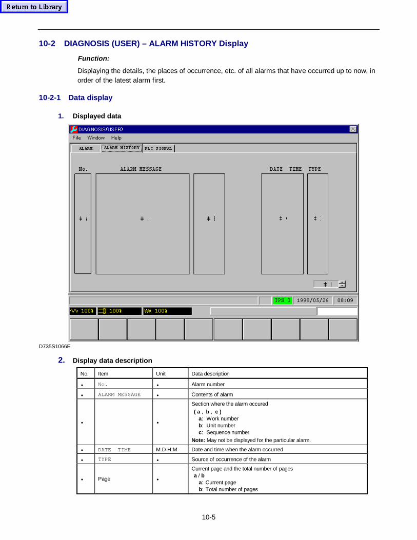
10-5
10-2 DIAGNOSIS (USER) – ALARM HISTORY Display
Function:
Displaying the details, the places of occurrence, etc. of all alarms that have occurred up to now, inorder of the latest alarm first.
10-2-1 Data display
1. Displayed data
 (
 ' & % $ #
D735S1066E
2. Display data description
No. Item Unit Data description
• No. • Alarm number
• ALARM MESSAGE • Contents of alarm
• •
Section where the alarm occured
( a , b , c )a: Work numberb: Unit numberc: Sequence number
Note: May not be displayed for the particular alarm.
• DATE TIME M.D H:M Date and time when the alarm occurred
• TYPE • Source of occurrence of the alarm
• Page •
Current page and the total number of pagesa / b
a: Current pageb: Total number of pages
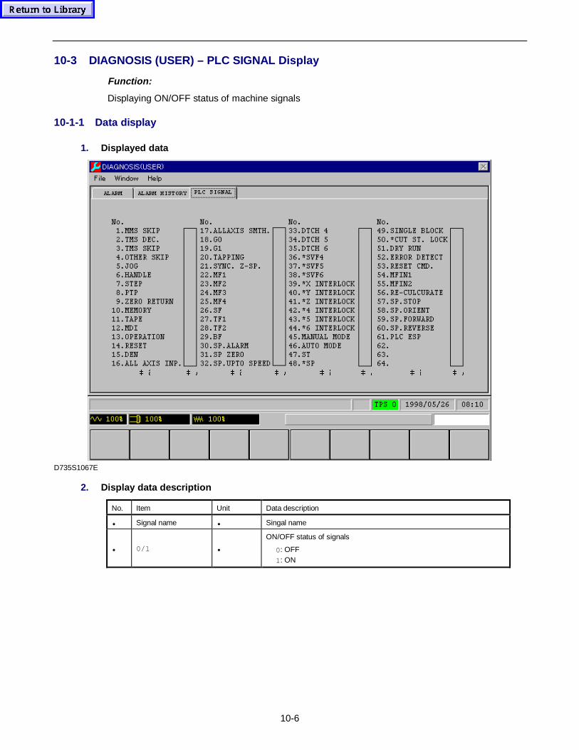
10-6
10-3 DIAGNOSIS (USER) – PLC SIGNAL Display
Function:
Displaying ON/OFF status of machine signals
10-1-1 Data display
1. Displayed data
 $ # $ # $ # $ #
D735S1067E
2. Display data description
No. Item Unit Data description
• Signal name • Singal name
• 0/1 •
ON/OFF status of signals
0: OFF1: ON
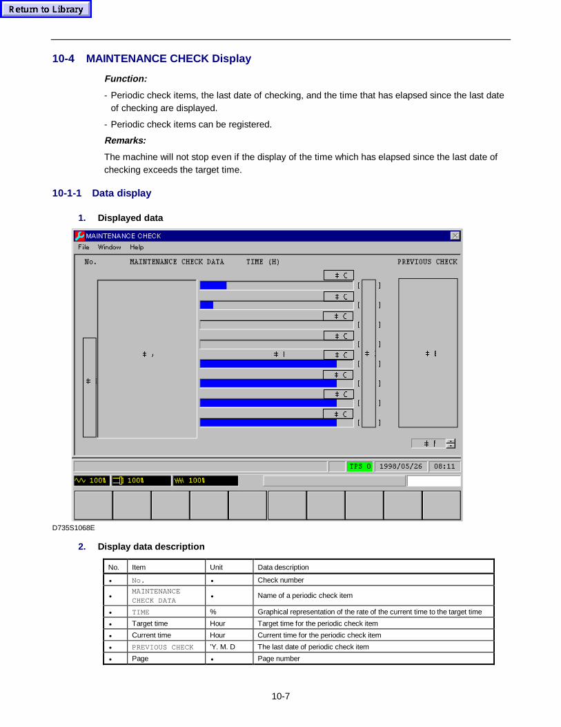
10-7
10-4 MAINTENANCE CHECK Display
Function:
- Periodic check items, the last date of checking, and the time that has elapsed since the last dateof checking are displayed.
- Periodic check items can be registered.
Remarks:
The machine will not stop even if the display of the time which has elapsed since the last date ofchecking exceeds the target time.
10-1-1 Data display
1. Displayed data
 &
 &
 &
 &
 #
 )
 ( ' % $
 &
 &
 &
 &
D735S1068E
2. Display data description
No. Item Unit Data description
• No. • Check number
•MAINTENANCECHECK DATA
• Name of a periodic check item
• TIME % Graphical representation of the rate of the current time to the target time
• Target time Hour Target time for the periodic check item
• Current time Hour Current time for the periodic check item
• PREVIOUS CHECK ’Y. M. D The last date of periodic check item
• Page • Page number
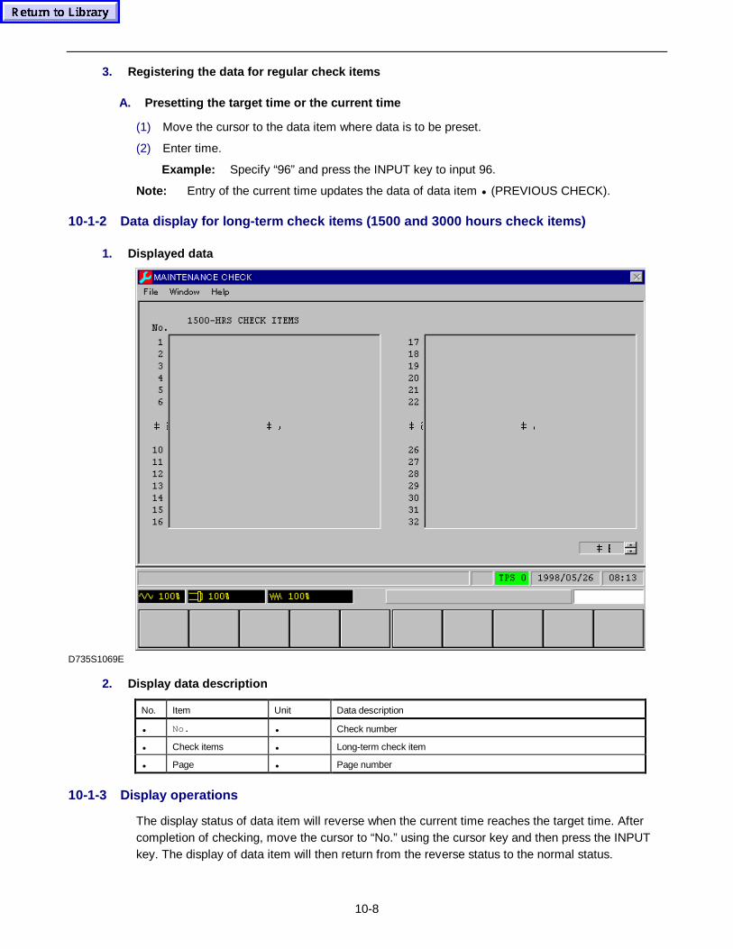
10-8
3. Registering the data for regular ch eck items
A. Presett ing the target time or the cu rrent time
(1) Move the cursor to the data item where data is to be preset.
(2) Enter time.
Example: Specify “96” and press the INPUT key to input 96.
Note: Entry of the current time updates the data of data item • (PREVIOUS CHECK).
10-1-2 Data display for long-term check items (1500 and 3000 hours ch eck items)
1. Displayed data
 $ #
 %
 $ #
D735S1069E
2. Display data description
No. Item Unit Data description
• No. • Check number
• Check items • Long-term check item
• Page • Page number
10-1-3 Display operations
The display status of data item will reverse when the current time reaches the target time. Aftercompletion of checking, move the cursor to “No.” using the cursor key and then press the INPUTkey. The display of data item will then return from the reverse status to the normal status.
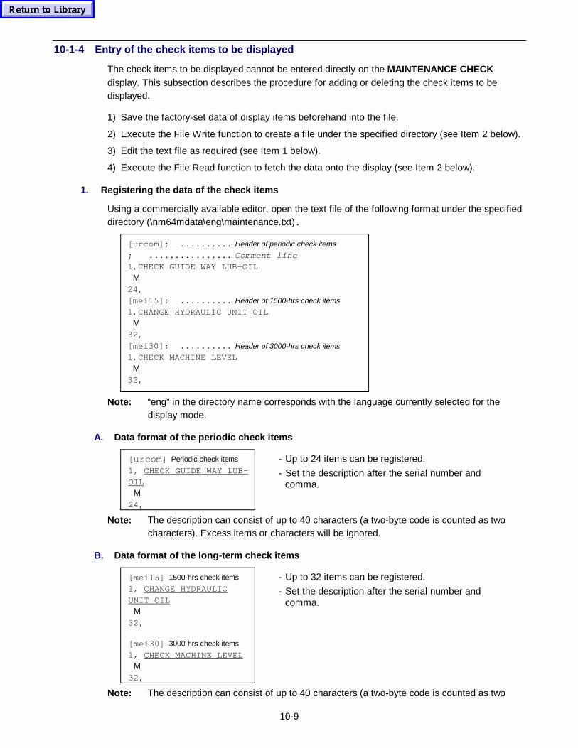
10-9
10-1-4 Entry of the check items to be displayed
The check items to be displayed cannot be entered directly on the MAINTENANCE CHECKdisplay. This subsection describes the procedure for adding or deleting the check items to bedisplayed.
1) Save the factory-set data of display items beforehand into the file.
2) Execute the File Write function to create a file under the specified directory (see Item 2 below).
3) Edit the text file as required (see Item 1 below).
4) Execute the File Read function to fetch the data onto the display (see Item 2 below).
1. Registering the data of the ch eck items
Using a commercially available editor, open the text file of the following format under the specifieddirectory (\nm64mdata\eng\maintenance.txt).
[urcom]; .......... Header of periodic check items
; ................ Comment line1,CHECK GUIDE WAY LUB-OIL Μ24,[mei15]; .......... Header of 1500-hrs check items
1,CHANGE HYDRAULIC UNIT OIL Μ32,[mei30]; .......... Header of 3000-hrs check items
1,CHECK MACHINE LEVEL Μ32,
Note: “eng” in the directory name corresponds with the language currently selected for thedisplay mode.
A. Data format of the per iodic ch eck items
[ urcom ] Periodic check items
1, CHECK GUIDE WAY LUB-OIL Μ24,
- Up to 24 items can be registered.
- Set the description after the serial number andcomma.
Note: The description can consist of up to 40 characters (a two-byte code is counted as twocharacters). Excess items or characters will be ignored.
B. Data format of the long-t erm check items
[mei15] 1500-hrs check items
1, CHANGE HYDRAULICUNIT OIL Μ32,
[mei30] 3000-hrs check items
1, CHECK MACHINE LEVEL Μ32,
- Up to 32 items can be registered.
- Set the description after the serial number andcomma.
Note: The description can consist of up to 40 characters (a two-byte code is counted as two
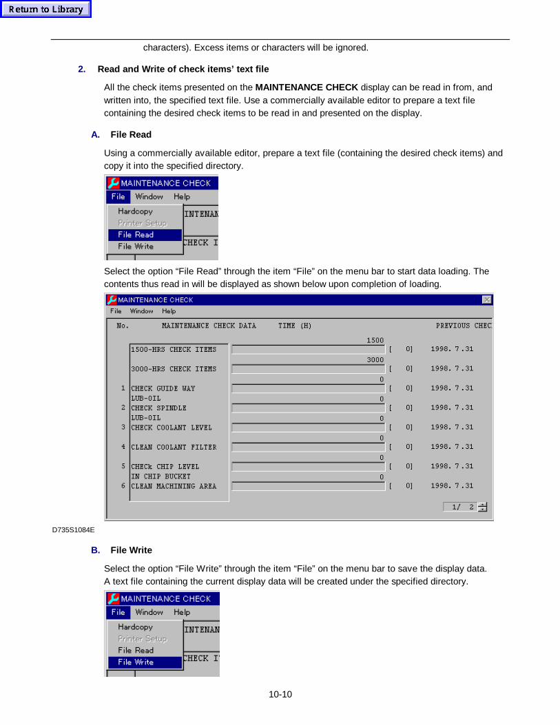
10-10
characters). Excess items or characters will be ignored.
2. Read and Write of check items’ text file
All the check items presented on the MAINTENANCE CHECK display can be read in from, andwritten into, the specified text file. Use a commercially available editor to prepare a text filecontaining the desired check items to be read in and presented on the display.
A. File Read
Using a commercially available editor, prepare a text file (containing the desired check items) andcopy it into the specified directory.
Select the option “File Read” through the item “File” on the menu bar to start data loading. Thecontents thus read in will be displayed as shown below upon completion of loading.
D735S1084E
B. File Write
Select the option “File Write” through the item “File” on the menu bar to save the display data.A text file containing the current display data will be created under the specified directory.
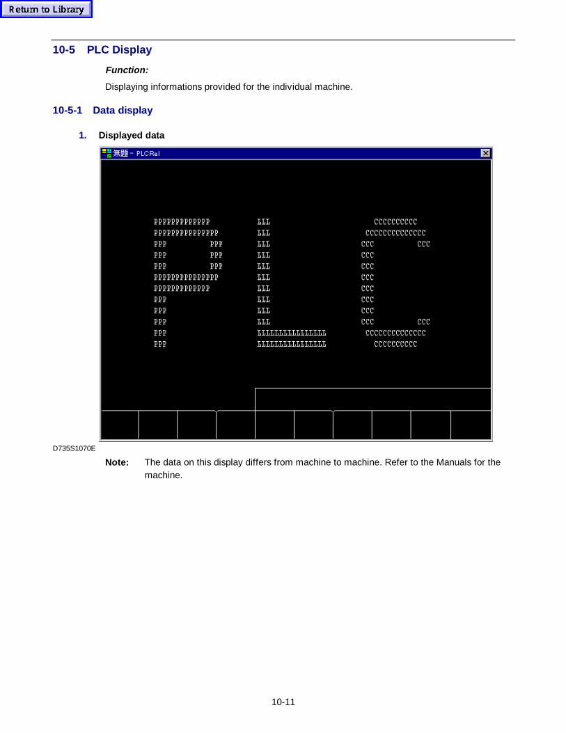
10-11
10-5 PLC Display
Function:
Displaying informations provided for the individual machine.
10-5-1 Data display
1. Displayed data
D735S1070E
Note: The data on this display differs from machine to machine. Refer to the Manuals for themachine.
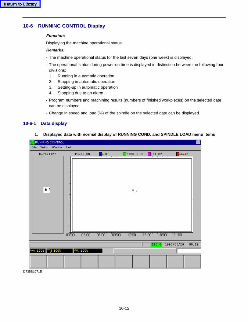
10-12
10-6 RUNNING CONTROL Display
Function:
Displaying the machine operational status.
Remarks:
- The machine operational status for the last seven days (one week) is displayed.
- The operational status during power-on time is displayed in distinction between the following fourdivisions:1. Running in automatic operation2. Stopping in automatic operation3. Setting-up in automatic operation4. Stopping due to an alarm
- Program numbers and machining results (numbers of finished workpieces) on the selected datecan be displayed.
- Change in speed and load (%) of the spindle on the selected date can be displayed.
10-6-1 Data display
1. Displayed data with normal display of RUNNING COND. and SPINDLE LOAD menu items
 $ #
D735S1071E
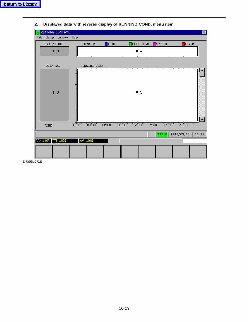
10-13
2. Displayed data with reverse display of RUNNING COND. menu item
 %
 #
 &
 $
D735S1072E
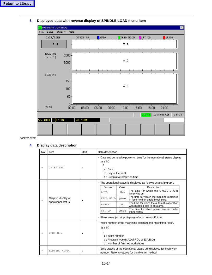
10-14
3. Displayed data with reverse display of SPINDLE LOAD menu item
 #
 (
 '
 $
D735S1073E
4. Display data description
No. Item Unit Data description
• DATE/TIME •
- Date and cumulative power-on time for the operational status displaya ( b ) c
a : Dateb : Day of the weekc : Cumulative power-on time
•Graphic display ofoperational status
•
- The operational status is displayed as follows on a strip graph:
Division Color Description
AUTO blue The time for which the CYCLE STARTlamp was on.
FEED HOLD green The time for which the machine remainedin feed-hold or single-block stop.
ALARM red The time for which the automatic operationwas disabled due to an alarm.
SET UP purple The time for which power was on underother states.
- Blank areas (no strip display) refer to power-off time.
• WORK No. •
- Work number of the machining program and machining result.
a ( b ) c
a : Work numberb : Program type (MAZATROL or EIA/ISO)c : Number of finished workpieces
• RUNNING COND. •- Strip graphs of the operational status are displayed for each work
number. Refer to• above for the division method.
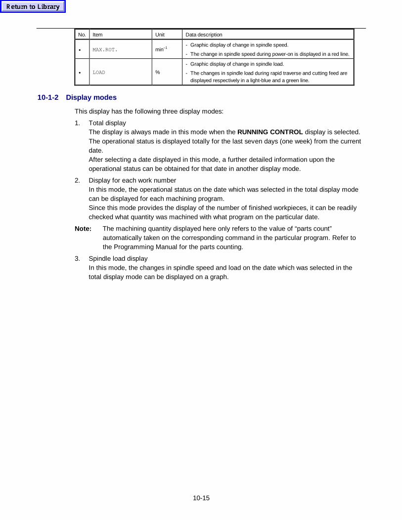
10-15
No. Item Unit Data description
• MAX.ROT. min–1- Graphic display of change in spindle speed.
- The change in spindle speed during power-on is displayed in a red line.
• LOAD %
- Graphic display of change in spindle load.
- The changes in spindle load during rapid traverse and cutting feed aredisplayed respectively in a light-blue and a green line.
10-1-2 Display modes
This display has the following three display modes:
1. Total displayThe display is always made in this mode when the RUNNING CONTROL display is selected.The operational status is displayed totally for the last seven days (one week) from the currentdate.After selecting a date displayed in this mode, a further detailed information upon theoperational status can be obtained for that date in another display mode.
2. Display for each work numberIn this mode, the operational status on the date which was selected in the total display modecan be displayed for each machining program.Since this mode provides the display of the number of finished workpieces, it can be readilychecked what quantity was machined with what program on the particular date.
Note: The machining quantity displayed here only refers to the value of “parts count”automatically taken on the corresponding command in the particular program. Refer tothe Programming Manual for the parts counting.
3. Spindle load displayIn this mode, the changes in spindle speed and load on the date which was selected in thetotal display mode can be displayed on a graph.
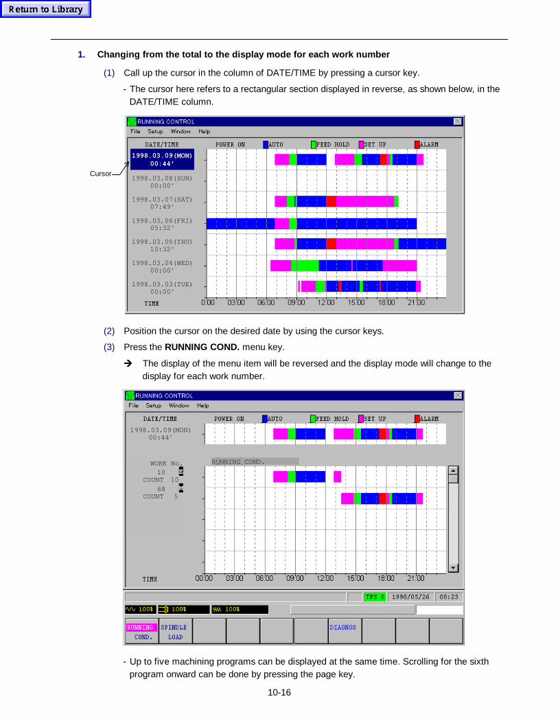
10-16
1. Changing from the total to the display mode for each work number
(1) Call up the cursor in the column of DATE/TIME by pressing a cursor key.
- The cursor here refers to a rectangular section displayed in reverse, as shown below, in theDATE/TIME column.
Cursor1998.03.08(SUN)
00:00’
1998.03.07(SAT)07:49’
1998.03,06(FRI)05:32’
1998.03.05(THU)10:32’
1998.03.04(WED)00:00’
1998.03.03(TUE)00:00’
1998.03.09(MON)00:44’
(2) Position the cursor on the desired date by using the cursor keys.
(3) Press the RUNNING COND. menu key.
Î The display of the menu item will be reversed and the display mode will change to thedisplay for each work number.
RUNNING COND.WORK No.10 E
COUNT 1068 M
COUNT 5
1998.03.09(MON)00:44’
- Up to five machining programs can be displayed at the same time. Scrolling for the sixthprogram onward can be done by pressing the page key.
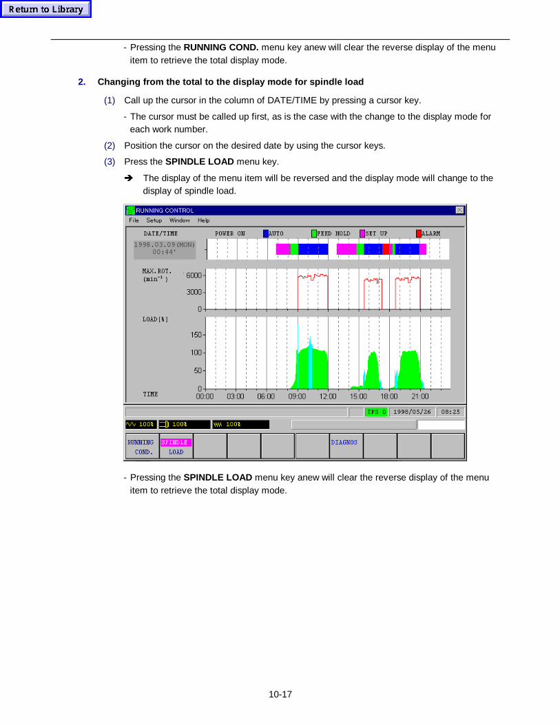
10-17
- Pressing the RUNNING COND. menu key anew will clear the reverse display of the menuitem to retrieve the total display mode.
2. Changing from the total to the display mode for spindle load
(1) Call up the cursor in the column of DATE/TIME by pressing a cursor key.
- The cursor must be called up first, as is the case with the change to the display mode foreach work number.
(2) Position the cursor on the desired date by using the cursor keys.
(3) Press the SPINDLE LOAD menu key.
Î The display of the menu item will be reversed and the display mode will change to thedisplay of spindle load.
1998.03.09(MON)00:44’
- Pressing the SPINDLE LOAD menu key anew will clear the reverse display of the menuitem to retrieve the total display mode.
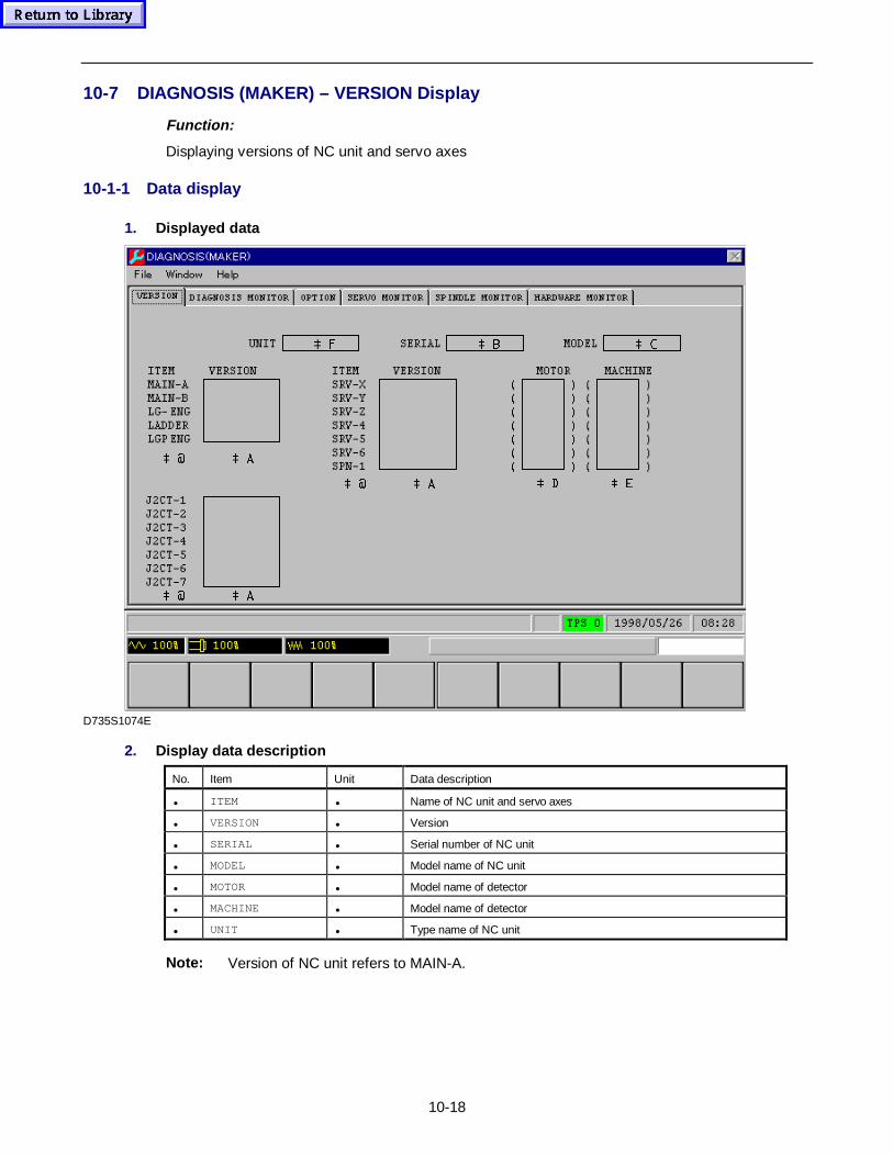
10-18
10-7 DIAGNOSIS (MAKER) – VERSION Display
Function:
Displaying versions of NC unit and servo axes
10-1-1 Data display
1. Displayed data
 #  $
 & )  %
 #  $  '  (
 #  $
D735S1074E
2. Display data description
No. Item Unit Data description
• ITEM • Name of NC unit and servo axes
• VERSION • Version
• SERIAL • Serial number of NC unit
• MODEL • Model name of NC unit
• MOTOR • Model name of detector
• MACHINE • Model name of detector
• UNIT • Type name of NC unit
Note: Version of NC unit refers to MAIN-A.
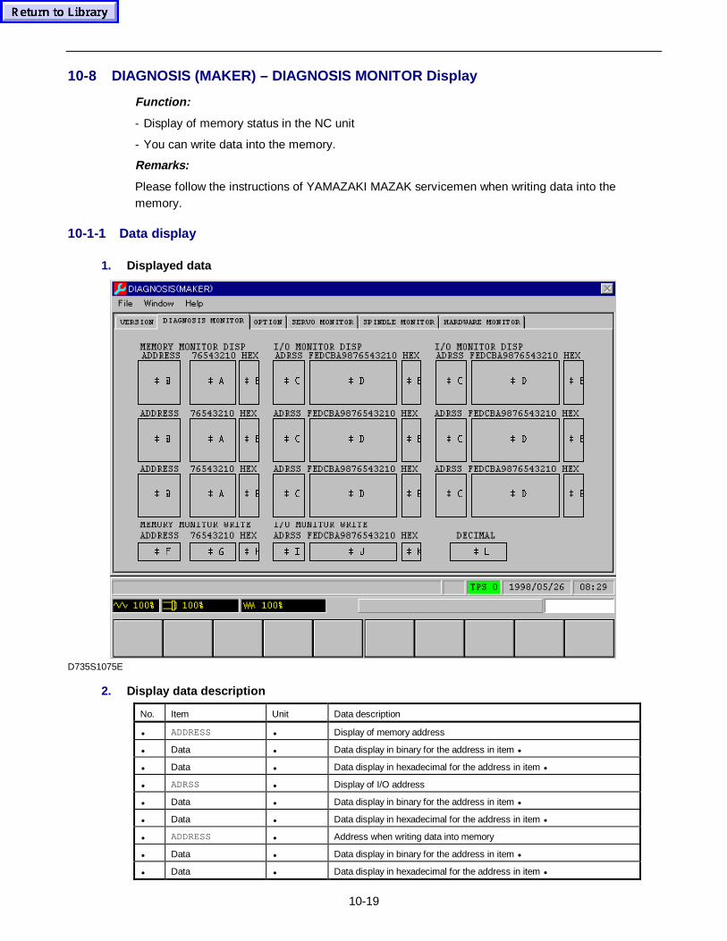
10-19
10-8 DIAGNOSIS (MAKER) – DIAGNOSIS MONITOR Display
Function:
- Display of memory status in the NC unit
- You can write data into the memory.
Remarks:
Please follow the instructions of YAMAZAKI MAZAK servicemen when writing data into thememory.
10-1-1 Data display
1. Displayed data
 $ #  %  ' &  (  ' &  (
 $ #  %  ' &  (  ' &  (
 $ #  %  ' &  (  ' &  (
 * )  +  - ,  .  /
D735S1075E
2. Display data description
No. Item Unit Data description
• ADDRESS • Display of memory address
• Data • Data display in binary for the address in item •
• Data • Data display in hexadecimal for the address in item •
• ADRSS • Display of I/O address
• Data • Data display in binary for the address in item •
• Data • Data display in hexadecimal for the address in item •
• ADDRESS • Address when writing data into memory
• Data • Data display in binary for the address in item •
• Data • Data display in hexadecimal for the address in item •
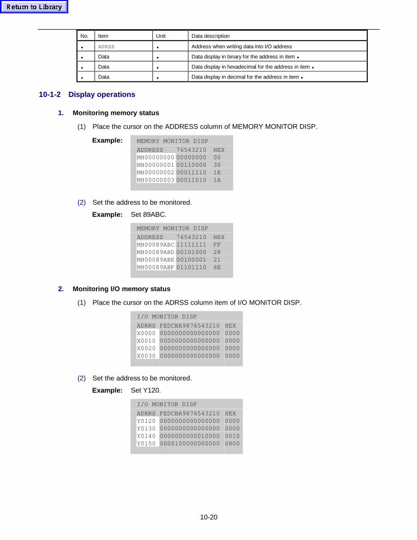
10-20
No. Item Unit Data description
• ADRSS • Address when writing data into I/O address
• Data • Data display in binary for the address in item •
• Data • Data display in hexadecimal for the address in item •
• Data • Data display in decimal for the address in item •
10-1-2 Display operations
1. Monitoring memory status
(1) Place the cursor on the ADDRESS column of MEMORY MONITOR DISP.
Example: MEMORY MONITOR DISP
ADDRESS 76543210 HEXMH00000000MH00000001MH00000002MH00000003
00000000001100000001111000011010
00301E1A
(2) Set the address to be monitored.
Example: Set 89ABC.
MEMORY MONITOR DISP
ADDRESS 76543210 HEXMH00089ABCMH00089ABDMH00089ABEMH00089ABF
11111111001010000010000101101110
FF28216E
2. Monitoring I/O memory status
(1) Place the cursor on the ADRSS column item of I/O MONITOR DISP.
I/O MONITOR DISP
ADRRSFEDCBA9876543210 HEXX0000X0010X0020X0030
0000000000000000000000000000000000000000000000000000000000000000
0000000000000000
(2) Set the address to be monitored.
Example: Set Y120.
I/O MONITOR DISP
ADRRSFEDCBA9876543210 HEXY0120Y0130Y0140Y0150
0000000000000000000000000000000000000000000100000000100000000000
0000000000100800
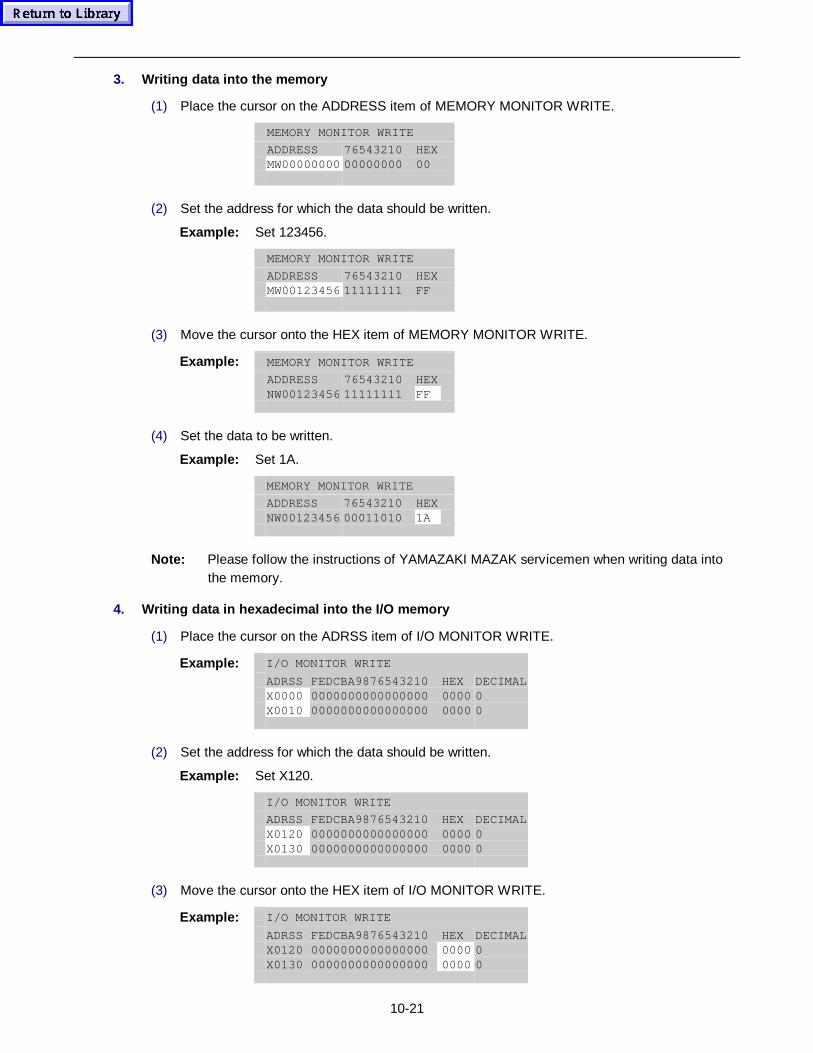
10-21
3. Writing data into the memory
(1) Place the cursor on the ADDRESS item of MEMORY MONITOR WRITE.
MEMORY MONITOR WRITE
ADDRESS 76543210 HEXMW0000000000000000 00
(2) Set the address for which the data should be written.
Example: Set 123456.
MEMORY MONITOR WRITE
ADDRESS 76543210 HEXMW0012345611111111 FF
(3) Move the cursor onto the HEX item of MEMORY MONITOR WRITE.
Example: MEMORY MONITOR WRITE
ADDRESS 76543210 HEXNW00123456 11111111 FF
(4) Set the data to be written.
Example: Set 1A.
MEMORY MONITOR WRITE
ADDRESS 76543210 HEXNW00123456 00011010 1A
Note: Please follow the instructions of YAMAZAKI MAZAK servicemen when writing data intothe memory.
4. Writing data in h exadecimal into the I/O memory
(1) Place the cursor on the ADRSS item of I/O MONITOR WRITE.
Example: I/O MONITOR WRITE
ADRSS FEDCBA9876543210 HEX DECIMALX0000 0000000000000000 0000 0X0010 0000000000000000 0000 0
(2) Set the address for which the data should be written.
Example: Set X120.
I/O MONITOR WRITE
ADRSS FEDCBA9876543210 HEX DECIMALX0120 0000000000000000 0000 0X0130 0000000000000000 0000 0
(3) Move the cursor onto the HEX item of I/O MONITOR WRITE.
Example: I/O MONITOR WRITE
ADRSS FEDCBA9876543210 HEX DECIMALX0120 0000000000000000 0000 0X0130 0000000000000000 0000 0
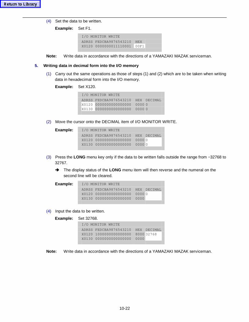
10-22
(4) Set the data to be written.
Example: Set F1.
I/O MONITOR WRITE
ADRSS FEDCBA9876543210 HEXX0120 0000000011110001 00F1
Note: Write data in accordance with the directions of a YAMAZAKI MAZAK serviceman.
5. Writing data in decimal form into the I/O memory
(1) Carry out the same operations as those of steps (1) and (2) which are to be taken when writingdata in hexadecimal form into the I/O memory.
Example: Set X120.
I/O MONITOR WRITE
ADRSS FEDCBA9876543210 HEX DECIMALX0120 0000000000000000 0000 0X0130 0000000000000000 0000 0
(2) Move the cursor onto the DECIMAL item of I/O MONITOR WRITE.
Example: I/O MONITOR WRITE
ADRSS FEDCBA9876543210 HEX DECIMALX0120 0000000000000000 0000 0X0130 0000000000000000 0000 0
(3) Press the LONG menu key only if the data to be written falls outside the range from −32768 to32767.
Î The display status of the LONG menu item will then reverse and the numeral on thesecond line will be cleared.
Example: I/O MONITOR WRITE
ADRSS FEDCBA9876543210 HEX DECIMALX0120 0000000000000000 0000 0X0130 0000000000000000 0000
(4) Input the data to be written.
Example: Set 32768.I/O MONITOR WRITE
ADRSS FEDCBA9876543210 HEX DECIMALX0120 1000000000000000 8000 32768X0130 0000000000000000 0000
Note: Write data in accordance with the directions of a YAMAZAKI MAZAK serviceman.
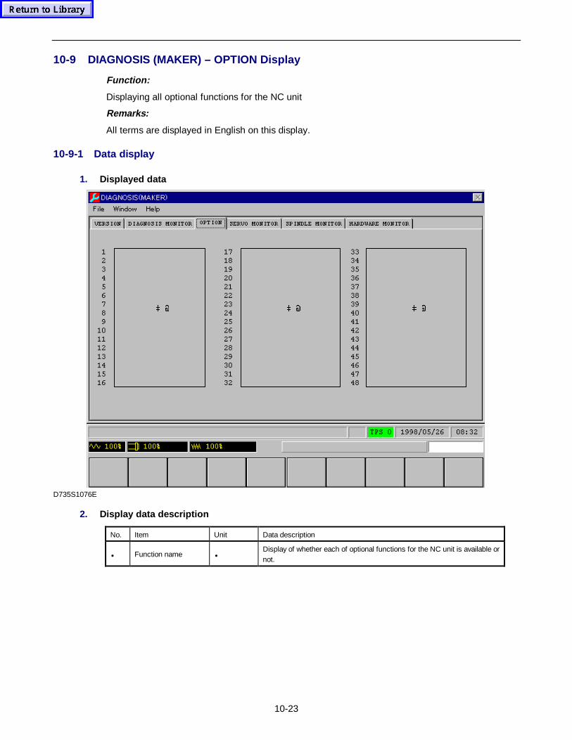
10-23
10-9 DIAGNOSIS (MAKER) – OPTION Display
Function:
Displaying all optional functions for the NC unit
Remarks:
All terms are displayed in English on this display.
10-9-1 Data display
1. Displayed data
 # # #
D735S1076E
2. Display data description
No. Item Unit Data description
• Function name •Display of whether each of optional functions for the NC unit is available ornot.

10-24
- NOTE -
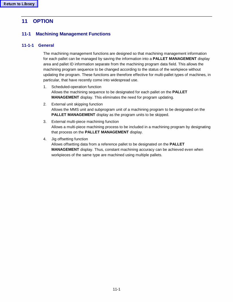
11-1
11 OPTION
11-1 Machining Management Functions
11-1-1 General
The machining management functions are designed so that machining management informationfor each pallet can be managed by saving the information into a PALLET MANAGEMENT displayarea and pallet ID information separate from the machining program data field. This allows themachining program sequence to be changed according to the status of the workpiece withoutupdating the program. These functions are therefore effective for multi-pallet types of machines, inparticular, that have recently come into widespread use.
1. Scheduled-operation functionAllows the machining sequence to be designated for each pallet on the PALLETMANAGEMENT display. This eliminates the need for program updating.
2. External unit skipping functionAllows the MMS unit and subprogram unit of a machining program to be designated on thePALLET MANAGEMENT display as the program units to be skipped.
3. External multi-piece machining functionAllows a multi-piece machining process to be included in a machining program by designatingthat process on the PALLET MANAGEMENT display.
4. Jig offsetting functionAllows offsetting data from a reference pallet to be designated on the PALLETMANAGEMENT display. Thus, constant machining accuracy can be achieved even whenworkpieces of the same type are machined using multiple pallets.
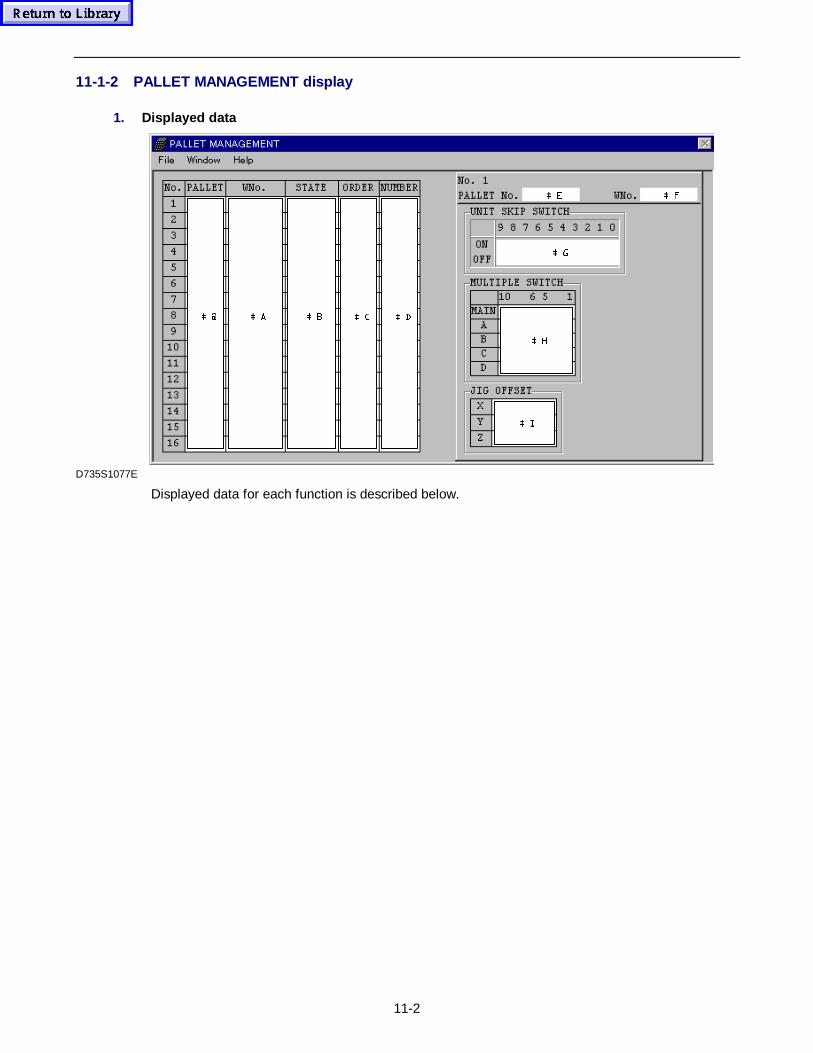
11-2
11-1-2 PALLET MANAGEMENT display
1. Displayed data
 ,
 +
 *
 ) (
 ' & % $ #
D735S1077E
Displayed data for each function is described below.
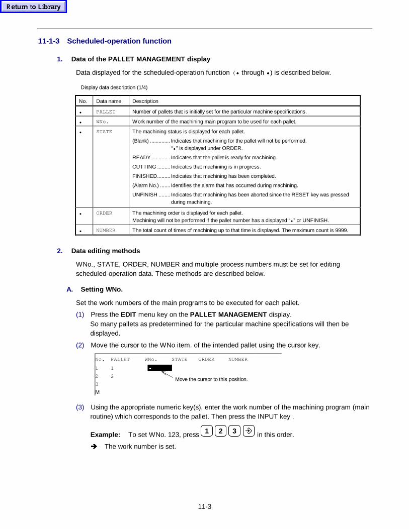
11-3
11-1-3 Scheduled-operation function
1. Data of the PALLET MANAGEMENT display
Data displayed for the scheduled-operation function (• through • ) is described below.
Display data description (1/4)
No. Data name Description
• PALLET Number of pallets that is initially set for the particular machine specifications.
• WNo. Work number of the machining main program to be used for each pallet.
• STATE The machining status is displayed for each pallet.
(Blank) .............. Indicates that machining for the pallet will not be performed.“• ” is displayed under ORDER.
READY ............. Indicates that the pallet is ready for machining.
CUTTING ......... Indicates that machining is in progress.
FINISHED......... Indicates that machining has been completed.
(Alarm No.) ....... Identifies the alarm that has occurred during machining.
UNFINISH ........ Indicates that machining has been aborted since the RESET key was pressedduring machining.
• ORDER The machining order is displayed for each pallet.Machining will not be performed if the pallet number has a displayed “• ” or UNFINISH.
• NUMBER The total count of times of machining up to that time is displayed. The maximum count is 9999.
2. Data editing methods
WNo., STATE, ORDER, NUMBER and multiple process numbers must be set for editingscheduled-operation data. These methods are described below.
A. Setting WNo.
Set the work numbers of the main programs to be executed for each pallet.
(1) Press the EDIT menu key on the PALLET MANAGEMENT display.So many pallets as predetermined for the particular machine specifications will then bedisplayed.
(2) Move the cursor to the WNo item. of the intended pallet using the cursor key.
No. PALLET WNo. STATE ORDER NUMBER
1 1 •
2 2
3
Μ
(3) Using the appropriate numeric key(s), enter the work number of the machining program (mainroutine) which corresponds to the pallet. Then press the INPUT key .
Example: To set WNo. 123, press 1 2 3 in this order.
Î The work number is set.
Move the cursor to this position.
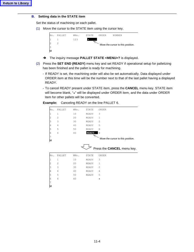
11-4
B. Setting data in the STATE item
Set the status of machining on each pallet.
(1) Move the cursor to the STATE item using the cursor key.
No. PALLET WNo. STATE ORDER NUMBER
1 1 123 •
2 2
3
Μ
Î The inquiry message PALLET STATE <MENU>? is displayed.
(2) Press the SET END (READY) menu key and set READY if operational setup for palletizinghas been finished and the pallet is ready for machining.
- If READY is set, the machining order will also be set automatically. Data displayed underORDER item at this time will be the number next to that of the last pallet having a displayedREADY.
- To cancel READY present under STATE item, press the CANCEL menu key. STATE itemwill become blank, “• ” will be displayed under ORDER item, and the data under ORDERitem for other pallets will be converted.
Example: Canceling READY on the line PALLET 6.
No. PALLET WNo. STATE ORDER
1 1 10 READY 3
2 2 20 READY 1
3 3 30 READY 2
4 4 40 READY 5
5 5 50 READY 6
6 6 60 READY 4
7
Μ
Press the CANCEL menu key.
No. PALLET WNo. STATE ORDER
1 1 10 READY 3
2 2 20 READY 1
3 3 30 READY 2
4 4 40 READY 4
5 5 50 READY 5
6 6 60 •
7
Μ
Move the cursor to this position.
Move the cursor to this position.
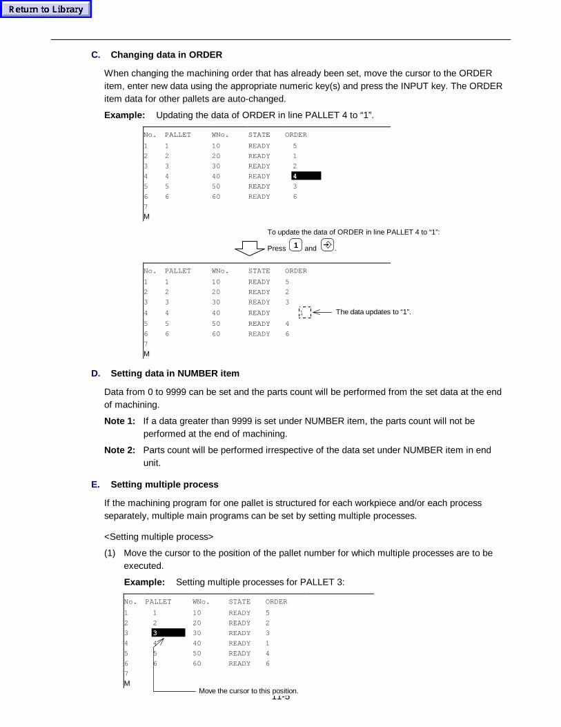
11-5
C. Changing data in ORDER
When changing the machining order that has already been set, move the cursor to the ORDERitem, enter new data using the appropriate numeric key(s) and press the INPUT key. The ORDERitem data for other pallets are auto-changed.
Example: Updating the data of ORDER in line PALLET 4 to “1”.
No. PALLET WNo. STATE ORDER
1 1 10 READY 5
2 2 20 READY 1
3 3 30 READY 2
4 4 40 READY 4
5 5 50 READY 3
6 6 60 READY 6
7
Μ
To update the data of ORDER in line PALLET 4 to “1”:
Press 1 and .
No. PALLET WNo. STATE ORDER
1 1 10 READY 5
2 2 20 READY 2
3 3 30 READY 3
4 4 40 READY 1
5 5 50 READY 4
6 6 60 READY 6
7
Μ
D. Setting data in NUMBER item
Data from 0 to 9999 can be set and the parts count will be performed from the set data at the endof machining.
Note 1: If a data greater than 9999 is set under NUMBER item, the parts count will not beperformed at the end of machining.
Note 2: Parts count will be performed irrespective of the data set under NUMBER item in endunit.
E. Setting multiple pro cess
If the machining program for one pallet is structured for each workpiece and/or each processseparately, multiple main programs can be set by setting multiple processes.
<Setting multiple process>
(1) Move the cursor to the position of the pallet number for which multiple processes are to beexecuted.
Example: Setting multiple processes for PALLET 3:
No. PALLET WNo. STATE ORDER
1 1 10 READY 5
2 2 20 READY 2
3 3 30 READY 3
4 4 40 READY 1
5 5 50 READY 4
6 6 60 READY 6
7
Μ
The data updates to “1”.
Move the cursor to this position.
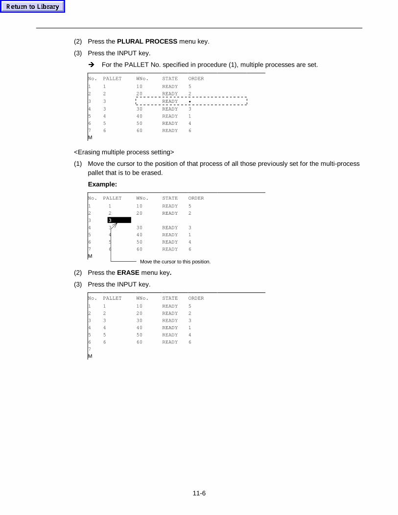
11-6
(2) Press the PLURAL PROCESS menu key.
(3) Press the INPUT key.
Î For the PALLET No. specified in procedure (1), multiple processes are set.
No. PALLET WNo. STATE ORDER
1 1 10 READY 5
2 2 20 READY 2
3 3 READY •
4 3 30 READY 3
5 4 40 READY 1
6 5 50 READY 4
7 6 60 READY 6
Μ
<Erasing multiple process setting>
(1) Move the cursor to the position of that process of all those previously set for the multi-processpallet that is to be erased.
Example:
No. PALLET WNo. STATE ORDER
1 1 10 READY 5
2 2 20 READY 2
3 3
4 3 30 READY 3
5 4 40 READY 1
6 5 50 READY 4
7 6 60 READY 6
Μ
(2) Press the ERASE menu key.
(3) Press the INPUT key.
No. PALLET WNo. STATE ORDER
1 1 10 READY 5
2 2 20 READY 2
3 3 30 READY 3
4 4 40 READY 1
5 5 50 READY 4
6 6 60 READY 6
7
Μ
Move the cursor to this position.
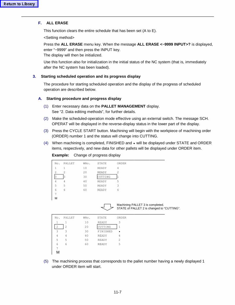
11-7
F. ALL ERASE
This function clears the entire schedule that has been set (A to E).
<Setting method>
Press the ALL ERASE menu key. When the message ALL ERASE < −9999 INPUT>? is displayed,enter “−9999” and then press the INPUT key.The display will then be initialized.
Use this function also for initialization in the initial status of the NC system (that is, immediatelyafter the NC system has been loaded).
3. Starting scheduled op erat ion and its prog ress display
The procedure for starting scheduled operation and the display of the progress of scheduledoperation are described below.
A. Starting procedure and prog ress display
(1) Enter necessary data on the PALLET MANAGEMENT display.See “2. Data editing methods”, for further details.
(2) Make the scheduled-operation mode effective using an external switch. The message SCH.OPERAT will be displayed in the reverse-display status in the lower part of the display.
(3) Press the CYCLE START button. Machining will begin with the workpiece of machining order(ORDER) number 1 and the status will change into CUTTING.
(4) When machining is completed, FINISHED and • will be displayed under STATE and ORDERitems, respectively, and new data for other pallets will be displayed under ORDER item.
Example: Change of progress display
No. PALLET WNo. STATE ORDER
1 1 10 READY 4
2 2 20 READY 2
3 3 30 CUTTING 1
4 4 40 READY 5
5 5 50 READY 3
6 6 60 READY 6
7
Μ
Machining PALLET 3 is completed.STATE of PALLET 2 is changed to “CUTTING”.
No. PALLET WNo. STATE ORDER
1 1 10 READY 3
2 2 20 CUTTING 1
3 3 30 FINISHED •
4 4 40 READY 4
5 5 50 READY 2
6 6 60 READY 5
7
Μ
(5) The machining process that corresponds to the pallet number having a newly displayed 1under ORDER item will start.
11-8
B. Precaut ions
1. Editing in the scheduled-operation mode
- Even during scheduled operation, editing can be done on the PALLET MANAGEMENTdisplay, except for the line of 1 under ORDER item (machining now in progress).See “2. Data editing methods”, for further details of editing.
- If the machining for the pallet of CUTTING is finished during EDIT mode, the machine willbe stopped. In this case, press the EDIT END menu key, then press CYCLE START buttonto continue machining.
2. Restarting in the scheduled-operation modeRestarting in the scheduled-operation mode can be done in the following case only:
- If the work number for ORDER 1 is the same as that displayed on the POSITION display.
Note: If the UNIT SKIP SWITCH is ON, execution of that unit will be skipped and theimmediately succeeding unit will be executed.
3. Other precautions
- Pressing the RESET key changes CUTTING to UNFINISH. To perform machining for thepallet anew, set READY under STATE.
- If an alarm occurs during machining, the alarm will be processed as follows:
1) The alarm number is displayed under STATE.
2) • is displayed under ORDER, and the machining order is updated.
3) If the alarm is of such a type that machining can be continued, the machining operationwill start from the machining program preset for the next process. If machining cannot becontinued, it will terminate on occurrence of the alarm.
Note: Do not set a multi-process program that enables machining to be done only after thepreprocess has been completed. If such a program is set and an alarm occurs, theprevious process will remain aborted and the next process will begin. Use a subprogramif such programming is required.
!CAUTION
z The external switch must be turned off when machining is to be done in the normal mode.If machining is done in the scheduled-operation mode, scheduled operation will be carriedout with automatically updated work numbers.When SCH. OPERAT is displayed in the reverse-display status in the lower part of thePOSITION display, then scheduled-operation is in effect.When SCH. OPERAT is not displayed on the POSITION display, then normal-modeoperation is in effect.
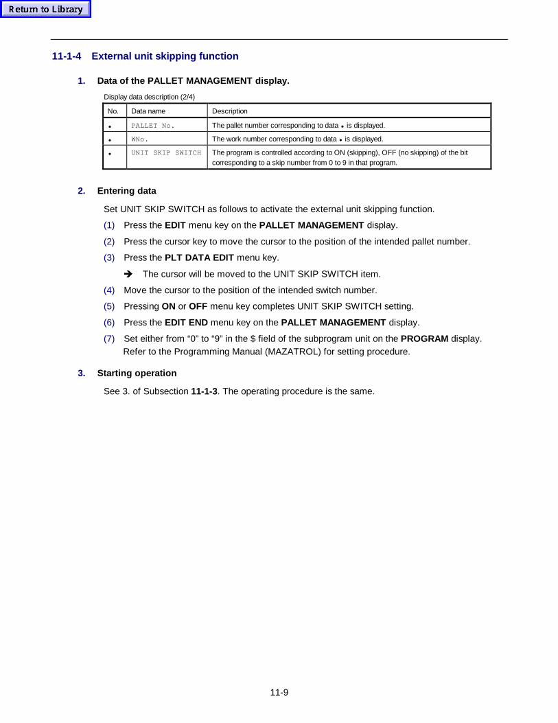
11-9
11-1-4 External unit skipping function
1. Data of the PALLET MANAGEMENT display.
Display data description (2/4)
No. Data name Description
• PALLET No. The pallet number corresponding to data • is displayed.
• WNo. The work number corresponding to data • is displayed.
• UNIT SKIP SWITCH The program is controlled according to ON (skipping), OFF (no skipping) of the bitcorresponding to a skip number from 0 to 9 in that program.
2. Entering data
Set UNIT SKIP SWITCH as follows to activate the external unit skipping function.
(1) Press the EDIT menu key on the PALLET MANAGEMENT display.
(2) Press the cursor key to move the cursor to the position of the intended pallet number.
(3) Press the PLT DATA EDIT menu key.
Î The cursor will be moved to the UNIT SKIP SWITCH item.
(4) Move the cursor to the position of the intended switch number.
(5) Pressing ON or OFF menu key completes UNIT SKIP SWITCH setting.
(6) Press the EDIT END menu key on the PALLET MANAGEMENT display.
(7) Set either from “0” to “9” in the $ field of the subprogram unit on the PROGRAM display.Refer to the Programming Manual (MAZATROL) for setting procedure.
3. Starting op eration
See 3. of Subsection 11-1-3. The operating procedure is the same.
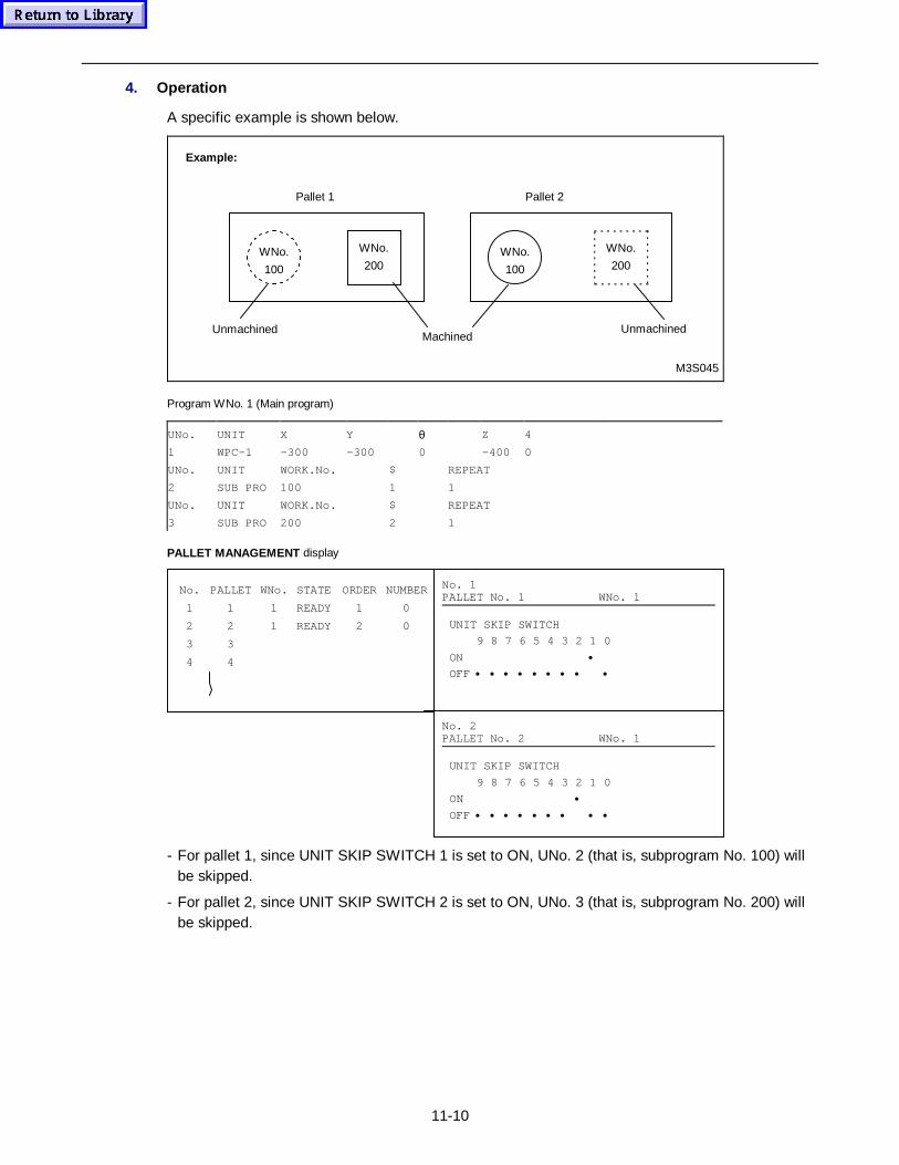
11-10
4. Operation
A specific example is shown below.
Pallet 1
WNo.
100
WNo.
200
MachinedUnmachinedUnmachined
Pallet 2
WNo.
100
M3S045
WNo.
200
Example:
Program WNo. 1 (Main program)
UNo. UNIT X Y θ Z 4
1 WPC-1 –300 –300 0 –400 0
UNo. UNIT WORK.No. $ REPEAT
2 SUB PRO 100 1 1
UNo. UNIT WORK.No. $ REPEAT
3 SUB PRO 200 2 1
PALLET MANAGEMENT display
No. PALLET WNo. STATE ORDER NUMBER
1 1 1 READY 1 0
2 2 1 READY 2 0
3 3
4 4
No. 2PALLET No. 2 WNo. 1
No. 1PALLET No. 1 WNo. 1
UNIT SKIP SWITCH
9 8 7 6 5 4 3 2 1 0
ON •
OFF • • • • • • • • •
UNIT SKIP SWITCH
9 8 7 6 5 4 3 2 1 0
ON •
OFF • • • • • • • • •
- For pallet 1, since UNIT SKIP SWITCH 1 is set to ON, UNo. 2 (that is, subprogram No. 100) willbe skipped.
- For pallet 2, since UNIT SKIP SWITCH 2 is set to ON, UNo. 3 (that is, subprogram No. 200) willbe skipped.
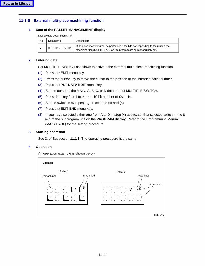
11-11
11-1-5 External multi-piece machining function
1. Data of the PALLET MANAGEMENT display.
Display data description (3/4)
No. Data name Description
• MULTIPLE SWITCHMulti-piece machining will be performed if the bits corresponding to the multi-piecemachining flag (MULTI FLAG) on the program are correspondingly set.
2. Entering data
Set MULTIPLE SWITCH as follows to activate the external multi-piece machining function.
(1) Press the EDIT menu key.
(2) Press the cursor key to move the cursor to the position of the intended pallet number.
(3) Press the PLT DATA EDIT menu key.
(4) Set the cursor to the MAIN, A, B, C, or D data item of MULTIPLE SWITCH.
(5) Press data key 0 or 1 to enter a 10-bit number of 0s or 1s.
(6) Set the switches by repeating procedures (4) and (5).
(7) Press the EDIT END menu key.
(8) If you have selected either one from A to D in step (4) above, set that selected switch in the $ield of the subprogram unit on the PROGRAM display. Refer to the Programming Manual(MAZATROL) for the setting procedure.
3. Starting op eration
See 3. of Subsection 11.1.3. The operating procedure is the same.
4. Operation
An operation example is shown below.
Example:
Pallet 1 Pallet 2
M3S046
Machined MachinedUnmachined
Unmachined
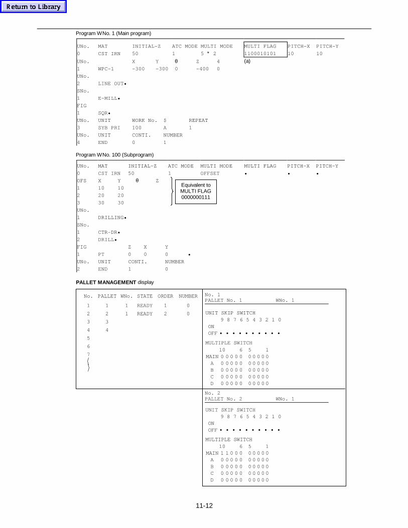
11-12
Program WNo. 1 (Main program)
UNo. MAT INITIAL-Z ATC MODE MULTI MODE MULTI FLAG PITCH-X PITCH-Y
0 CST IRN 50 1 5 ∗ 2 1100010101 10 10
UNo. X Y θ Z 4 (a)1 WPC-1 -300 -300 0 -400 0
UNo.
2 LINE OUT•
SNo.
1 E-MILL•
FIG
1 SQR•
UNo. UNIT WORK No. $ REPEAT
3 SYB PRI 100 A 1
UNo. UNIT CONTI. NUMBER
4 END 0 1
Program WNo. 100 (Subprogram)
UNo. MAT INITIAL-Z ATC MODE MULTI MODE MULTI FLAG PITCH-X PITCH-Y
0 CST IRN 50 1 OFFSET • • •
OFS X Y θ Z
1
2
3
10
20
30
10
20
30
(b)
UNo.
1 DRILLING•
SNo.
1
2
CTR-DR•
DRILL•
FIG Z X Y
1 PT 0 0 0 •
UNo. UNIT CONTI. NUMBER
2 END 1 0
PALLET MANAGEMENT display
No. PALLET WNo. STATE ORDER NUMBER
1 1 1 READY 1 0
2 2 1 READY 2 0
3 3
4 4
5
6
7
No. 1PALLET No. 1 WNo. 1
UNIT SKIP SWITCH9 8 7 6 5 4 3 2 1 0
ON OFF • • • • • • • • • •
MULTIPLE SWITCH
10 6 5 1MAIN 0 0 0 0 0 0 0 0 0 0
A 0 0 0 0 0 0 0 0 0 0B 0 0 0 0 0 0 0 0 0 0C 0 0 0 0 0 0 0 0 0 0D 0 0 0 0 0 0 0 0 0 0
No. 2PALLET No. 2 WNo. 1
MULTIPLE SWITCH10 6 5 1
MAIN 1 1 0 0 0 0 0 0 0 0A 0 0 0 0 0 0 0 0 0 0B 0 0 0 0 0 0 0 0 0 0C 0 0 0 0 0 0 0 0 0 0D 0 0 0 0 0 0 0 0 0 0
UNIT SKIP SWITCH9 8 7 6 5 4 3 2 1 0
ON OFF • • • • • • • • • •
Equivalent toMULTI FLAG0000000111
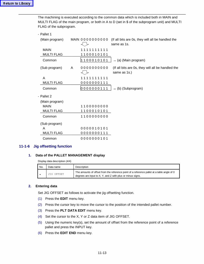
11-13
The machining is executed according to the common data which is included both in MAIN andMULTI FLAG of the main program, or both in A to D (set in $ of the subprogram unit) and MULTIFLAG of the subprogram.
- Pallet 1
(Main program) MAIN 0 0 0 0 0 0 0 0 0 0 (If all bits are 0s, they will all be handled thesame as 1s.
MAIN 1 1 1 1 1 1 1 1 1 1MULTI FLAG 1 1 0 0 0 1 0 1 0 1
Common 1 1 0 0 0 1 0 1 0 1 → (a) (Main program)
(Sub program) A 0 0 0 0 0 0 0 0 0 0 (If all bits are 0s, they will all be handled thesame as 1s.)
A 1 1 1 1 1 1 1 1 1 1MULTI FLAG 0 0 0 0 0 0 0 1 1 1
Common 0 0 0 0 0 0 0 1 1 1 → (b) (Subprogram)
- Pallet 2
(Main program)MAIN 1 1 0 0 0 0 0 0 0 0MULTI FLAG 1 1 0 0 0 1 0 1 0 1
Common 1 1 0 0 0 0 0 0 0 0
(Sub program)A 0 0 0 0 0 1 0 1 0 1MULTI FLAG 0 0 0 0 0 0 0 1 1 1
Common 0 0 0 0 0 0 0 1 0 1
11-1-6 Jig offsetting function
1. Data of the PALLET MANAGEMENT display
Display data description (4/4)
No. Data name Description
• JIG OFFSETThe amounts of offset from the reference point of a reference pallet at a table angle of 0degrees are input to X, Y, and Z with plus or minus signs.
2. Entering data
Set JIG OFFSET as follows to activate the jig offsetting function.
(1) Press the EDIT menu key.
(2) Press the cursor key to move the cursor to the position of the intended pallet number.
(3) Press the PLT DATA EDIT menu key.
(4) Set the cursor to the X, Y or Z data item of JIG OFFSET.
(5) Using the numeric key(s), set the amount of offset from the reference point of a referencepallet and press the INPUT key.
(6) Press the EDIT END menu key.
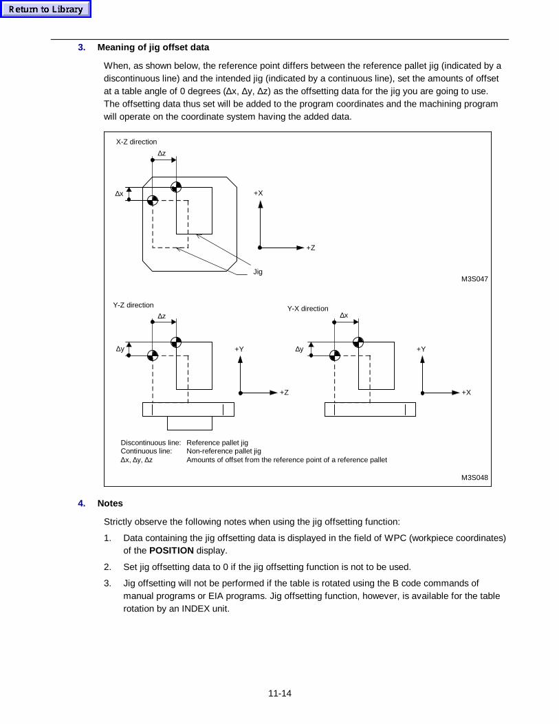
11-14
3. Meaning of jig offset data
When, as shown below, the reference point differs between the reference pallet jig (indicated by adiscontinuous line) and the intended jig (indicated by a continuous line), set the amounts of offsetat a table angle of 0 degrees (∆x, ∆y, ∆z) as the offsetting data for the jig you are going to use.The offsetting data thus set will be added to the program coordinates and the machining programwill operate on the coordinate system having the added data.
X-Z direction
Jig
∆z
∆x +X
+Z
Y-Z direction
M3S048
M3S047
∆z
∆y +Y
+Z
∆x
∆y +Y
+X
Y-X direction
Discontinuous line: Reference pallet jigContinuous line: Non-reference pallet jig∆x, ∆y, ∆z Amounts of offset from the reference point of a reference pallet
4. Notes
Strictly observe the following notes when using the jig offsetting function:
1. Data containing the jig offsetting data is displayed in the field of WPC (workpiece coordinates)of the POSITION display.
2. Set jig offsetting data to 0 if the jig offsetting function is not to be used.
3. Jig offsetting will not be performed if the table is rotated using the B code commands ofmanual programs or EIA programs. Jig offsetting function, however, is available for the tablerotation by an INDEX unit.
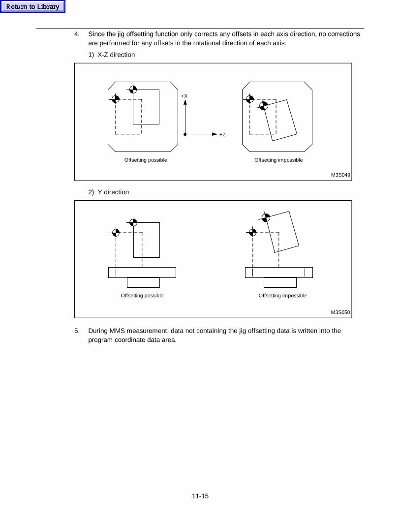
11-15
4. Since the jig offsetting function only corrects any offsets in each axis direction, no correctionsare performed for any offsets in the rotational direction of each axis.
1) X-Z direction
Offsetting impossibleOffsetting possible
+X
+Z
M3S049
2) Y direction
Offsetting impossibleOffsetting possible
M3S050
5. During MMS measurement, data not containing the jig offsetting data is written into theprogram coordinate data area.
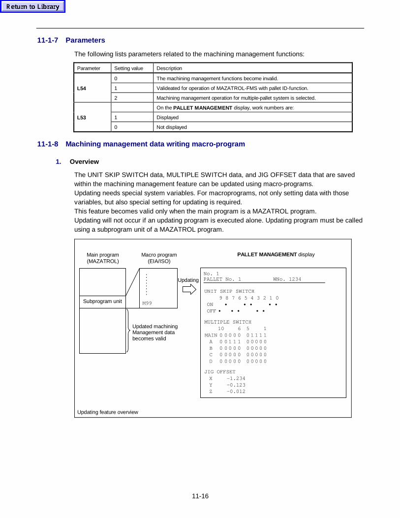
11-16
11-1-7 Parameters
The following lists parameters related to the machining management functions:
Parameter Setting value Description
0 The machining management functions become invalid.
1 Valideated for operation of MAZATROL-FMS with pallet ID-function.L54
2 Machining management operation for multiple-pallet system is selected.
On the PALLET MANAGEMENT display, work numbers are:
1 DisplayedL53
0 Not displayed
11-1-8 Machining management data writing macro-program
1. Overview
The UNIT SKIP SWITCH data, MULTIPLE SWITCH data, and JIG OFFSET data that are savedwithin the machining management feature can be updated using macro-programs.Updating needs special system variables. For macroprograms, not only setting data with thosevariables, but also special setting for updating is required.This feature becomes valid only when the main program is a MAZATROL program.Updating will not occur if an updating program is executed alone. Updating program must be calledusing a subprogram unit of a MAZATROL program.
Macro program(EIA/ISO)
Main program(MAZATROL)
PALLET MANAGEMENT display
Updating
Subprogram unit M99
Updating feature overview
Updated machiningManagement databecomes valid
No. 1PALLET No. 1 WNo. 1234
UNIT SKIP SWITCH9 8 7 6 5 4 3 2 1 0
ON • • • • • OFF • • • • •
JIG OFFSETX -1.234Y -0.123Z -0.012
MULTIPLE SWITCH10 6 5 1
MAIN 0 0 0 0 0 0 1 1 1 1A 0 0 1 1 1 0 0 0 0 0B 0 0 0 0 0 0 0 0 0 0C 0 0 0 0 0 0 0 0 0 0D 0 0 0 0 0 0 0 0 0 0
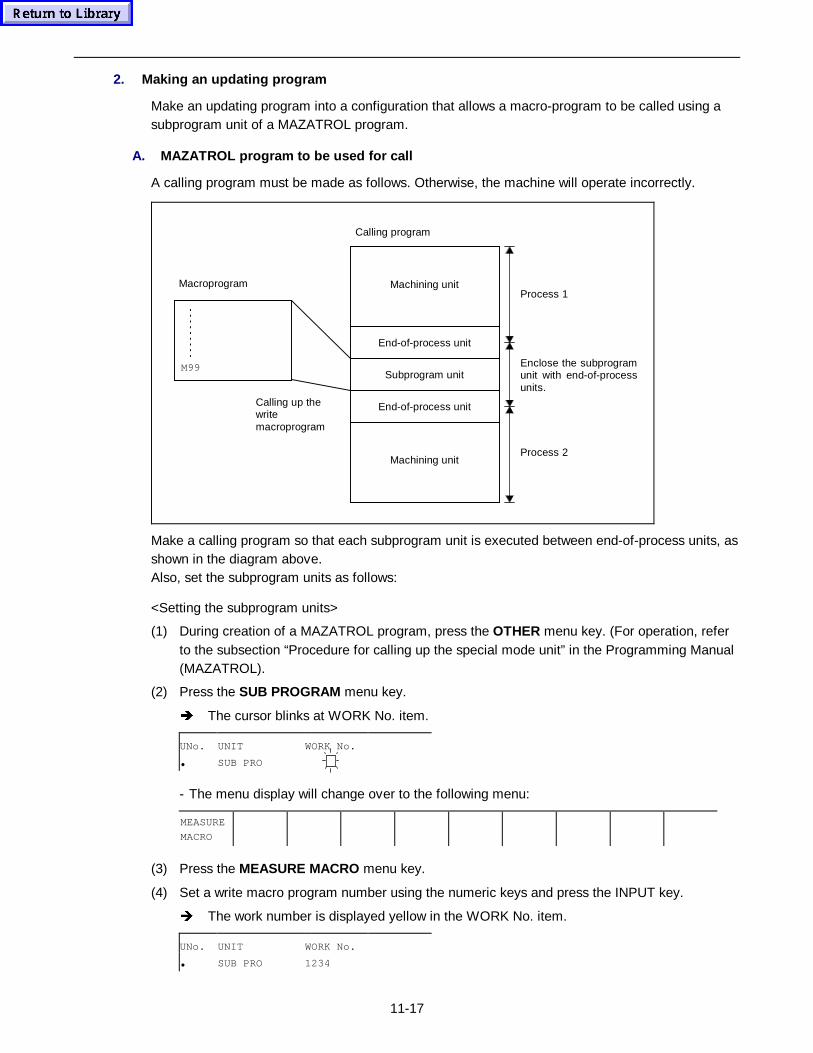
11-17
2. Making an updating program
Make an updating program into a configuration that allows a macro-program to be called using asubprogram unit of a MAZATROL program.
A. MAZATROL program to be used for call
A calling program must be made as follows. Otherwise, the machine will operate incorrectly.
Machining unit
End-of-process unit
Subprogram unit
End-of-process unit
Machining unit
Macroprogram
M99
Calling program
Calling up thewritemacroprogram
Process 1
Enclose the subprogramunit with end-of-processunits.
Process 2
Make a calling program so that each subprogram unit is executed between end-of-process units, asshown in the diagram above.Also, set the subprogram units as follows:
<Setting the subprogram units>
(1) During creation of a MAZATROL program, press the OTHER menu key. (For operation, referto the subsection “Procedure for calling up the special mode unit” in the Programming Manual(MAZATROL).
(2) Press the SUB PROGRAM menu key.
Î The cursor blinks at WORK No. item.
UNo. UNIT WORK No.
• SUB PRO
- The menu display will change over to the following menu:
MEASURE
MACRO
(3) Press the MEASURE MACRO menu key.
(4) Set a write macro program number using the numeric keys and press the INPUT key.
Î The work number is displayed yellow in the WORK No. item.
UNo. UNIT WORK No.
• SUB PRO 1234
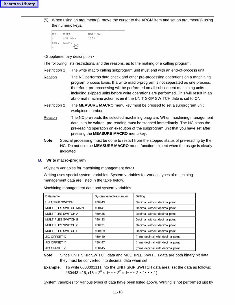
11-18
(5) When using an argument(s), move the cursor to the ARGM item and set an argument(s) usingthe numeric keys.
UNo. UNIT WORK No.
• SUB PRO 1234
SNo. ARGM1
1
<Supplementary description>
The following lists restrictions, and the reasons, as to the making of a calling program:
Restriction 1 The write macro calling subprogram unit must end with an end-of-process unit.
Reason The NC performs data check and other pre-processing operations on a machiningprogram process basis. If a write macro-program is not separated as one process,therefore, pre-processing will be performed on all subsequent machining unitsincluding skipped units before write operations are performed. This will result in anabnormal machine action even if the UNIT SKIP SWITCH data is set to ON.
Restriction 2 The MEASURE MACRO menu key must be pressed to set a subprogram unitworkpiece number.
Reason The NC pre-reads the selected machining program. When machining managementdata is to be written, pre-reading must be stopped immediately. The NC stops thepre-reading operation on execution of the subprogram unit that you have set afterpressing the MEASURE MACRO menu key.
Note: Special processing must be done to restart from the stopped status of pre-reading by theNC. Do not use the MEASURE MACRO menu function, except when the usage is clearlyindicated.
B. Write macro-program
<System variables for machining management data>
Writing uses special system variables. System variables for various types of machiningmanagement data are listed in the table below.
Machining management data and system variables
Data name System variables number Setting
UNIT SKIP SWITCH #50443 Decimal, without decimal point
MULTIPLES SWITCH MAIN #50441 Decimal, without decimal point
MULTIPLES SWITCH A #50435 Decimal, without decimal point
MULTIPLES SWITCH B #50433 Decimal, without decimal point
MULTIPLES SWITCH C #50431 Decimal, without decimal point
MULTIPLES SWITCH D #50429 Decimal, without decimal point
JIG OFFSET X #50449 (mm), decimal, with decimal point
JIG OFFSET Y #50447 (mm), decimal, with decimal point
JIG OFFSET Z #50445 (mm), decimal, with decimal point
Note: Since UNIT SKIP SWITCH data and MULTIPLE SWITCH data are both binary bit data,they must be converted into decimal data when set.
Example: To write 0000001111 into the UNIT SKIP SWITCH data area, set the data as follows:#50443 =15; (15 = 23 × 1• • • 22 × 1• • • 2 × 1• • • 1)
System variables for various types of data have been listed above. Writing is not performed just by
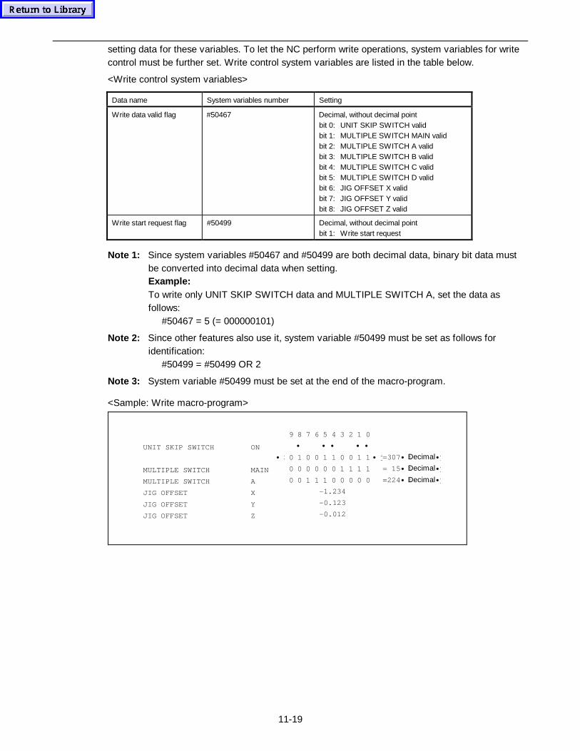
11-19
setting data for these variables. To let the NC perform write operations, system variables for writecontrol must be further set. Write control system variables are listed in the table below.
<Write control system variables>
Data name System variables number Setting
Write data valid flag #50467 Decimal, without decimal pointbit 0: UNIT SKIP SWITCH validbit 1: MULTIPLE SWITCH MAIN validbit 2: MULTIPLE SWITCH A validbit 3: MULTIPLE SWITCH B validbit 4: MULTIPLE SWITCH C validbit 5: MULTIPLE SWITCH D validbit 6: JIG OFFSET X validbit 7: JIG OFFSET Y validbit 8: JIG OFFSET Z valid
Write start request flag #50499 Decimal, without decimal pointbit 1: Write start request
Note 1: Since system variables #50467 and #50499 are both decimal data, binary bit data mustbe converted into decimal data when setting.Example:To write only UNIT SKIP SWITCH data and MULTIPLE SWITCH A, set the data asfollows:
#50467 = 5 (= 000000101)
Note 2: Since other features also use it, system variable #50499 must be set as follows foridentification:
#50499 = #50499 OR 2
Note 3: System variable #50499 must be set at the end of the macro-program.
<Sample: Write macro-program>
-1.234
-0.123
-0.012
UNIT SKIP SWITCH ON
MULTIPLE SWITCH MAIN
MULTIPLE SWITCH A
JIG OFFSET X
JIG OFFSET Y
JIG OFFSET Z
9 8 7 6 5 4 3 2 1 0
• Ÿ • Ÿ• Ÿ • Ÿ• Ÿ
• i 0 1 0 0 1 1 0 0 1 1 • j =307• iDecimal• j
0 0 0 0 0 0 1 1 1 1 = 15 • iDecimal• j
0 0 1 1 1 0 0 0 0 0 =224• iDecimal• j
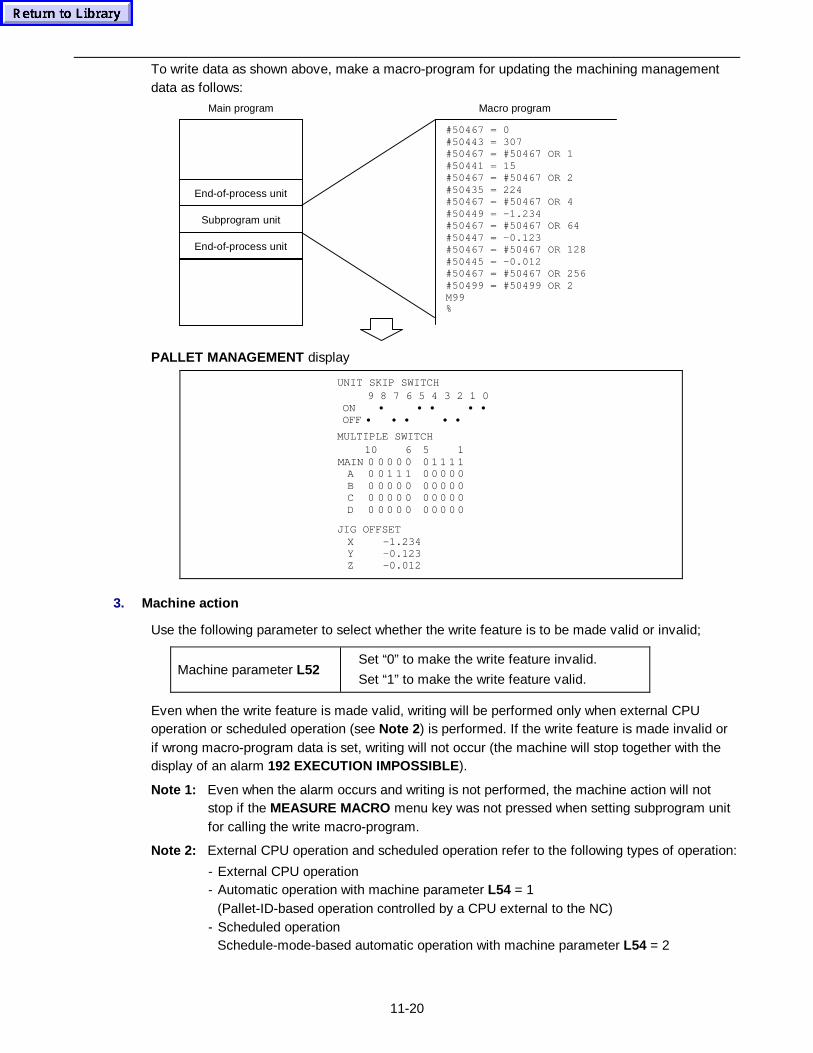
11-20
To write data as shown above, make a macro-program for updating the machining managementdata as follows:
Main program Macro program
End-of-process unit
Subprogram unit
End-of-process unit
#50467 = 0#50443 = 307#50467 = #50467 OR 1#50441 = 15#50467 = #50467 OR 2#50435 = 224#50467 = #50467 OR 4#50449 = -1.234#50467 = #50467 OR 64#50447 = -0.123#50467 = #50467 OR 128#50445 = -0.012#50467 = #50467 OR 256#50499 = #50499 OR 2M99%
PALLET MANAGEMENT display
UNIT SKIP SWITCH9 8 7 6 5 4 3 2 1 0
ON • • • • • OFF • • • • •
JIG OFFSETX -1.234Y -0.123Z -0.012
MULTIPLE SWITCH10 6 5 1
MAIN 0 0 0 0 0 0 1 1 1 1A 0 0 1 1 1 0 0 0 0 0B 0 0 0 0 0 0 0 0 0 0C 0 0 0 0 0 0 0 0 0 0D 0 0 0 0 0 0 0 0 0 0
3. Machine action
Use the following parameter to select whether the write feature is to be made valid or invalid;
Machine parameter L52Set “0” to make the write feature invalid.
Set “1” to make the write feature valid.
Even when the write feature is made valid, writing will be performed only when external CPUoperation or scheduled operation (see Note 2 ) is performed. If the write feature is made invalid orif wrong macro-program data is set, writing will not occur (the machine will stop together with thedisplay of an alarm 192 EXECUTION IMPOSSIBLE ).
Note 1: Even when the alarm occurs and writing is not performed, the machine action will notstop if the MEASURE MACRO menu key was not pressed when setting subprogram unitfor calling the write macro-program.
Note 2: External CPU operation and scheduled operation refer to the following types of operation:
- External CPU operation- Automatic operation with machine parameter L54 = 1
(Pallet-ID-based operation controlled by a CPU external to the NC)- Scheduled operation
Schedule-mode-based automatic operation with machine parameter L54 = 2
11-21
11-2 Function Relating EIA/ISO Program (Option)
EIA/ISO ONLY menu item will be displayed on the DIAGNOSIS (ALARM) if an EIA/ISOprogramming option is added. Pressing the menu key will reverse the display status of the menuitem and modify the display configuration and various data items into ones that can be moreconveniently used for EIA/ISO program.Pressing the menu key once again will clear the reverse-display status of the menu item and returnit to the normal status.
11-2-1 Configuration of displays
If the EIA/ISO ONLY menu item is reversed, the displays that the NC unit provides are of theconfiguration shown in the following pages.
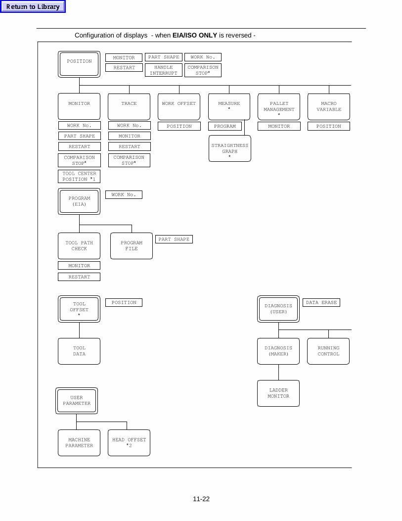
11-22
Configuration of displays - when EIA/ISO ONLY is reversed -
MONITOR
MONITOR PART SHAPE
RESTARTPOSITION
WORK No.
HANDLEINTERRUPT
WORK No. WORK No.
MONITOR
POSITION PROGRAM
WORK No.
TRACE WORK OFFSET MEASURE∗
PALLETMANAGEMENT
∗
MACROVARIABLE
RESTART
POSITIONMONITOR
PROGRAM(EIA)
TOOL PATHCHECK
RESTART
MONITOR
TOOLDATA
POSITIONTOOLOFFSET
∗
USERPARAMETER
DIAGNOSIS(MAKER)
DIAGNOSIS(USER)
RUNNINGCONTROL
LADDERMONITOR
MACHINEPARAMETER
COMPARISONSTOP∗
COMPARISONSTOP∗
COMPARISONSTOP∗
TOOL CENTERPOSITION ∗1
RESTART
PART SHAPE
HEAD OFFSET∗2
PROGRAMFILE
PART SHAPE
DATA ERASE
STRAIGHTNESSGRAPH
∗
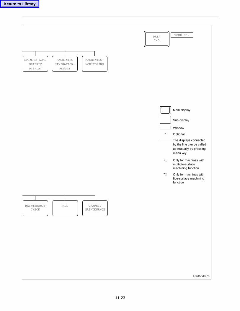
11-23
D735S1078
DATAI/O
WORK No.
MAINTENANCECHECK
PLC GRAPHICMAINTENANCE
∗
Main display
Sub-display
Window
Optional
The displays connectedby the line can be calledup mutually by pressingmenu key.
Only for machines withmultiple-surfacemachining function
Only for machines withfive-surface machiningfunction
∗1
∗2
MACHINING
NAVIGATION-
RESULT
MACHINING-
MONITORING
SPINDLE LOAD
GRAPHIC
DISPLAY
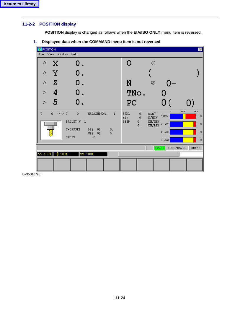
11-24
11-2-2 POSITION display
POSITION display is changed as follows when the EIA/ISO ONLY menu item is reversed.
1. Displayed data when the COMMAND menu item is not reversed
D735S1079E
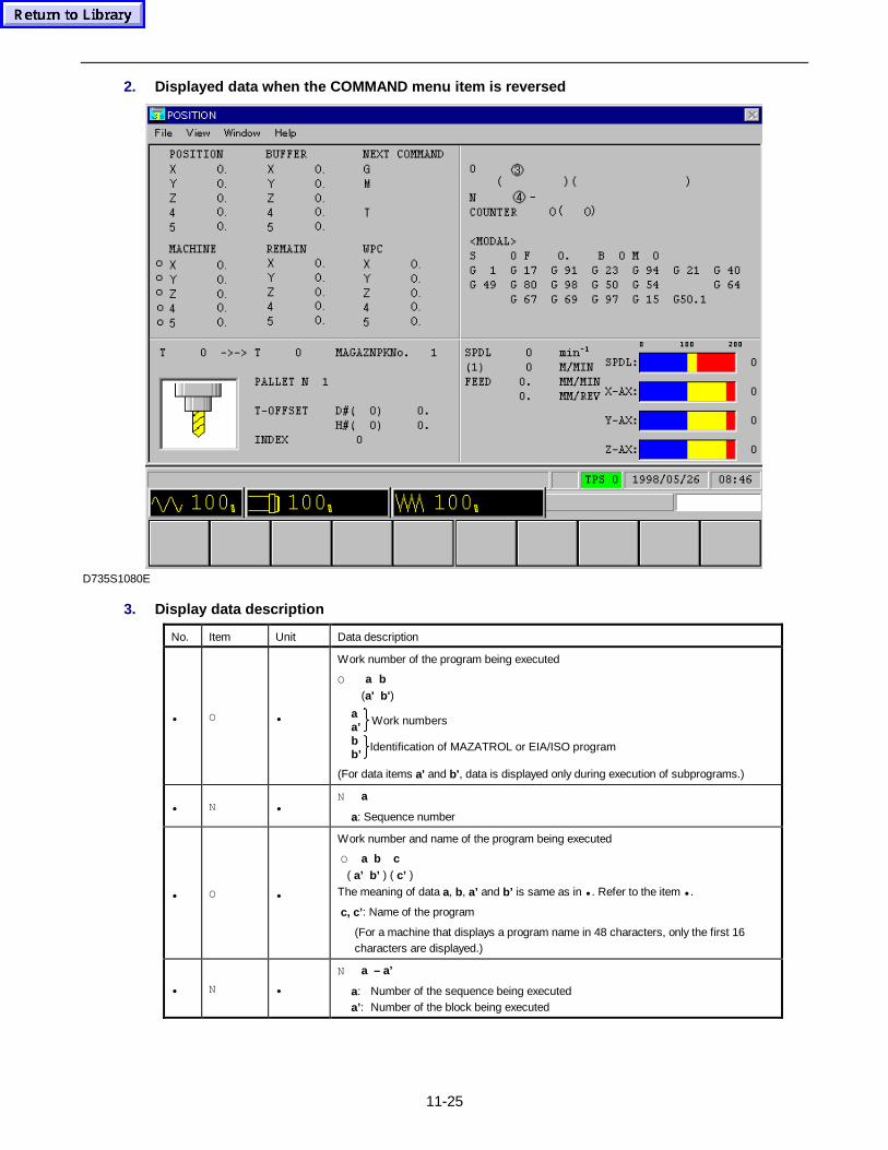
11-25
2. Displayed data when the COMMAND menu item is reversed
D735S1080E
3. Display data description
No. Item Unit Data description
• O •
Work number of the program being executed
O a b(a' b' )
Work numbers
Identification of MAZATROL or EIA/ISO program
aa’bb’
(For data items a' and b' , data is displayed only during execution of subprograms.)
• N •N a
a: Sequence number
• O •
Work number and name of the program being executed
O a b c ( a’ b’ ) ( c’ )The meaning of data a, b, a’ and b’ is same as in • . Refer to the item • .
c, c’ : Name of the program
(For a machine that displays a program name in 48 characters, only the first 16characters are displayed.)
• N •
N a – a’
a: Number of the sequence being executeda’: Number of the block being executed
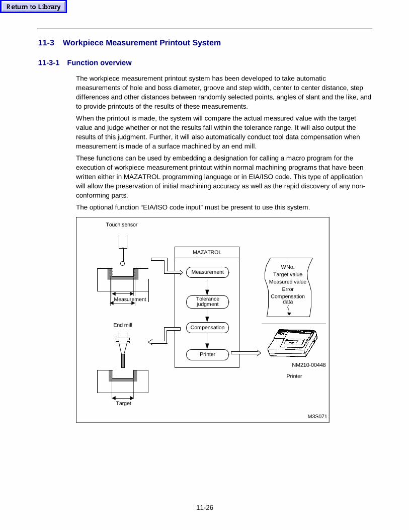
11-26
11-3 Workpiece Measurement Printout System
11-3-1 Function overview
The workpiece measurement printout system has been developed to take automaticmeasurements of hole and boss diameter, groove and step width, center to center distance, stepdifferences and other distances between randomly selected points, angles of slant and the like, andto provide printouts of the results of these measurements.
When the printout is made, the system will compare the actual measured value with the targetvalue and judge whether or not the results fall within the tolerance range. It will also output theresults of this judgment. Further, it will also automatically conduct tool data compensation whenmeasurement is made of a surface machined by an end mill.
These functions can be used by embedding a designation for calling a macro program for theexecution of workpiece measurement printout within normal machining programs that have beenwritten either in MAZATROL programming language or in EIA/ISO code. This type of applicationwill allow the preservation of initial machining accuracy as well as the rapid discovery of any non-conforming parts.
The optional function “EIA/ISO code input” must be present to use this system.
Touch sensor
MAZATROL
WNo.Target value
Measured valueError
Compensationdata
End mill
M3S071
Target
NM210-00448
Printer
Compensation
Tolerancejudgment
Measurement
Printer
Measurement
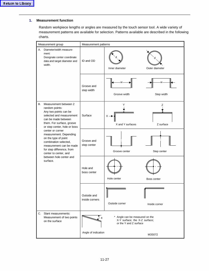
11-27
1. Measurement function
Random workpiece lengths or angles are measured by the touch sensor tool. A wide variety ofmeasurement patterns are available for selection. Patterns available are described in the followingcharts.
Measurement group Measurement patterns
ID and OD
Outer diameterInner diameter
d d
A. Diameter/width measure-ment:Designate center coordinatedata and target diameter andwidth.
Groove andstep width
Step widthGroove width
w w
Surface
Z surfaceX and Y surfaces
X
Y Z
Groove andstep center
Step centerGroove center
Hole andboss center
Hole center Boss center
B. Measurement between 2random points:Any two points can beselected and measurementcan be made betweenthem. For surface, grooveor step center, hole or bosscenter or cornermeasurement. Dependingon the type of pointcombination selected,measurement can be madefor step difference, fromcenter to center, andbetween hole center andsurface.
Outside andinside corners
Outside corner Inside corner
C. Slant measurements:Measurement of two pointson the surface
M3S072Angle of indication
a * Angle can be measured on theX-Y surface; the X-Z surface;or the Y and Z surface
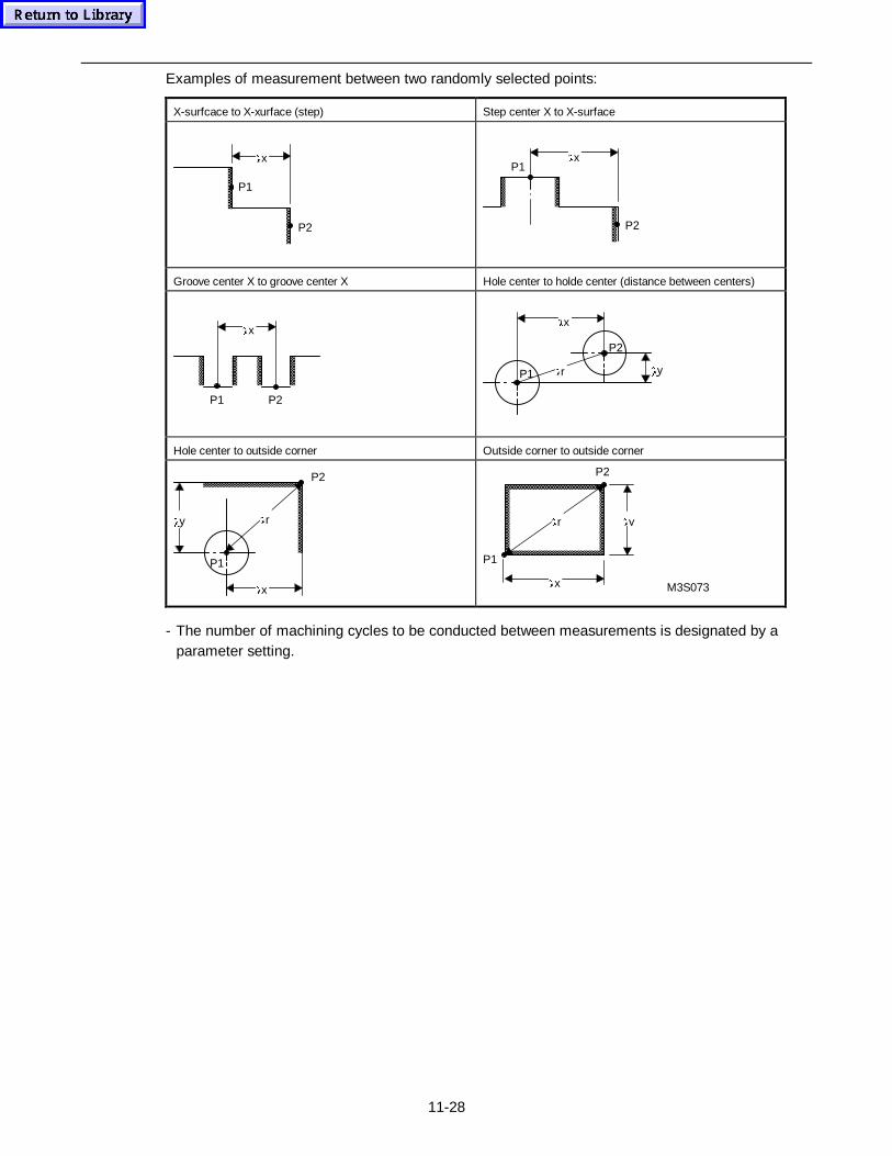
11-28
Examples of measurement between two randomly selected points:
X-surfcace to X-xurface (step) Step center X to X-surface
Ox
P1
P2
P1
P2
Ox
Groove center X to groove center X Hole center to holde center (distance between centers)
Ox
P1 P2
P2
P1 Or
Ox
Oy
Hole center to outside corner Outside corner to outside corner
P1
Ox
P2
OrOy
Ox
P2
M3S073
Oy
P1
Or
- The number of machining cycles to be conducted between measurements is designated by aparameter setting.
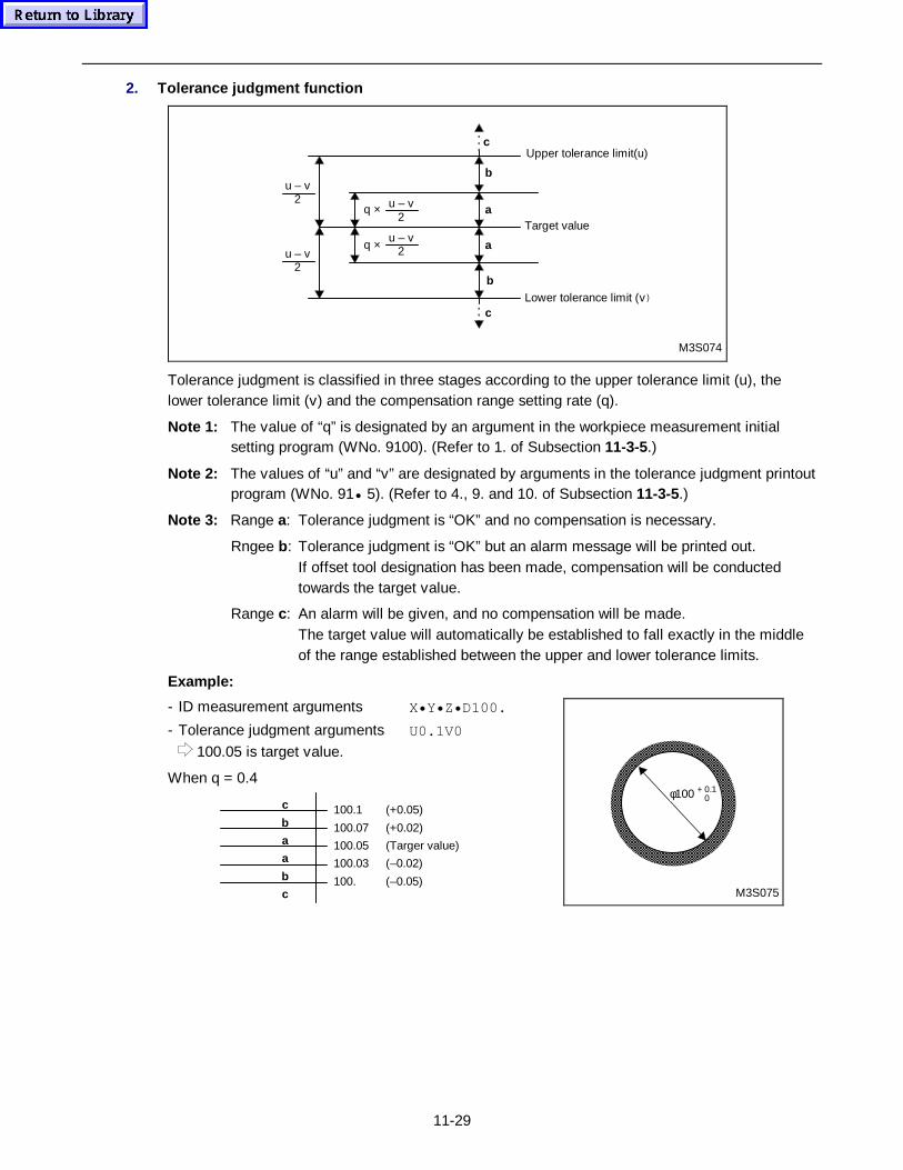
11-29
2. Tolerance judgment function
q ×
b
Upper tolerance limit(u)
M3S074
c
a
a
b
c
Target value
Lower tolerance limit (v)
q ×
u – v2
u – v2
u – v2
u – v2
Tolerance judgment is classified in three stages according to the upper tolerance limit (u), thelower tolerance limit (v) and the compensation range setting rate (q).
Note 1: The value of “q” is designated by an argument in the workpiece measurement initialsetting program (WNo. 9100). (Refer to 1. of Subsection 11-3-5.)
Note 2: The values of “u” and “v” are designated by arguments in the tolerance judgment printoutprogram (WNo. 91• 5). (Refer to 4., 9. and 10. of Subsection 11-3-5.)
Note 3: Range a: Tolerance judgment is “OK” and no compensation is necessary.
Rngee b: Tolerance judgment is “OK” but an alarm message will be printed out.If offset tool designation has been made, compensation will be conductedtowards the target value.
Range c: An alarm will be given, and no compensation will be made.The target value will automatically be established to fall exactly in the middleof the range established between the upper and lower tolerance limits.
Example:
- ID measurement arguments X• Y• Z• D100.
- Tolerance judgment arguments U0.1V0
100.05 is target value.
When q = 0.4
c
b
a
a
b
c
100.1 (+0.05)
100.07 (+0.02)
100.05 (Targer value)
100.03 (–0.02)
100. (–0.05)
φ100 + 0.1 0
M3S075
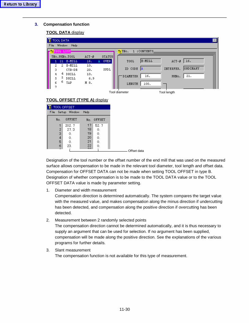
11-30
3. Compensation function
TOOL DATA display
Tool lengthTool diameter
TOOL OFFSET (TYPE A) display
Offset data
Designation of the tool number or the offset number of the end mill that was used on the measuredsurface allows compensation to be made in the relevant tool diameter, tool length and offset data.Compensation for OFFSET DATA can not be made when setting TOOL OFFSET in type B.Designation of whether compensation is to be made to the TOOL DATA value or to the TOOLOFFSET DATA value is made by parameter setting.
1. Diameter and width measurementCompensation direction is determined automatically. The system compares the target valuewith the measured value, and makes compensation along the minus direction if undercuttinghas been detected, and compensation along the positive direction if overcutting has beendetected.
2. Measurement between 2 randomly selected pointsThe compensation direction cannot be determined automatically, and it is thus necessary tosupply an argument that can be used for selection. If no argument has been supplied,compensation will be made along the positive direction. See the explanations of the variousprograms for further details.
3. Slant measurementThe compensation function is not available for this type of measurement.
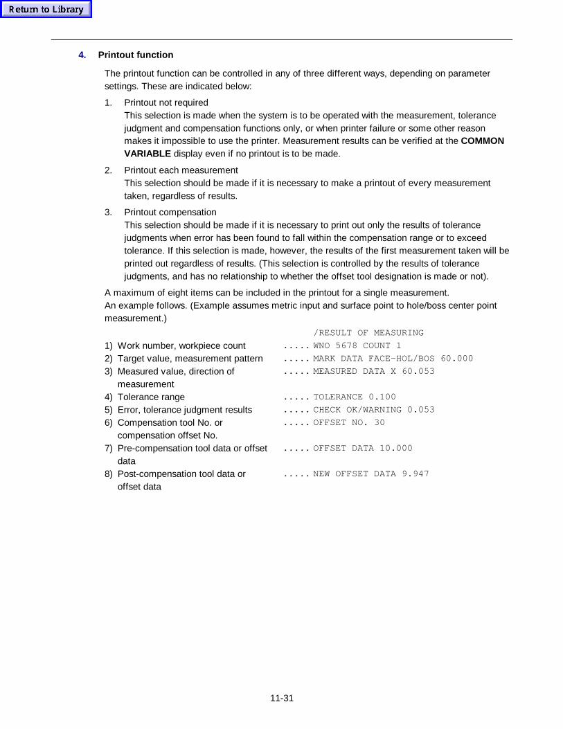
11-31
4. Printout function
The printout function can be controlled in any of three different ways, depending on parametersettings. These are indicated below:
1. Printout not requiredThis selection is made when the system is to be operated with the measurement, tolerancejudgment and compensation functions only, or when printer failure or some other reasonmakes it impossible to use the printer. Measurement results can be verified at the COMMONVARIABLE display even if no printout is to be made.
2. Printout each measurementThis selection should be made if it is necessary to make a printout of every measurementtaken, regardless of results.
3. Printout compensationThis selection should be made if it is necessary to print out only the results of tolerancejudgments when error has been found to fall within the compensation range or to exceedtolerance. If this selection is made, however, the results of the first measurement taken will beprinted out regardless of results. (This selection is controlled by the results of tolerancejudgments, and has no relationship to whether the offset tool designation is made or not).
A maximum of eight items can be included in the printout for a single measurement.An example follows. (Example assumes metric input and surface point to hole/boss center pointmeasurement.)
/RESULT OF MEASURING
1) Work number, workpiece count ..... WNO 5678 COUNT 1
2) Target value, measurement pattern ..... MARK DATA FACE-HOL/BOS 60.000
3) Measured value, direction ofmeasurement
..... MEASURED DATA X 60.053
4) Tolerance range ..... TOLERANCE 0.100
5) Error, tolerance judgment results ..... CHECK OK/WARNING 0.053
6) Compensation tool No. orcompensation offset No.
..... OFFSET NO. 30
7) Pre-compensation tool data or offsetdata
..... OFFSET DATA 10.000
8) Post-compensation tool data oroffset data
..... NEW OFFSET DATA 9.947
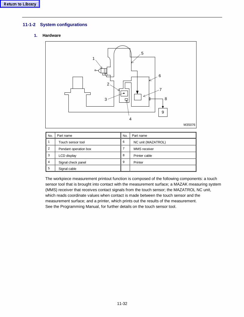
11-32
11-1-2 System configurations
1. Hardware
M3S076
5
6
7
1
2
3
4
8
9
No. Part name No. Part name
1 Touch sensor tool 6 NC unit (MAZATROL)
2 Pendant operation box 7 MMS receiver
3 LCD display 8 Printer cable
4 Signal check panel 9 Printer
5 Signal cable
The workpiece measurement printout function is composed of the following components: a touchsensor tool that is brought into contact with the measurement surface; a MAZAK measuring system(MMS) receiver that receives contact signals from the touch sensor; the MAZATROL NC unit,which reads coordinate values when contact is made between the touch sensor and themeasurement surface; and a printer, which prints out the results of the measurement.See the Programming Manual, for further details on the touch sensor tool.
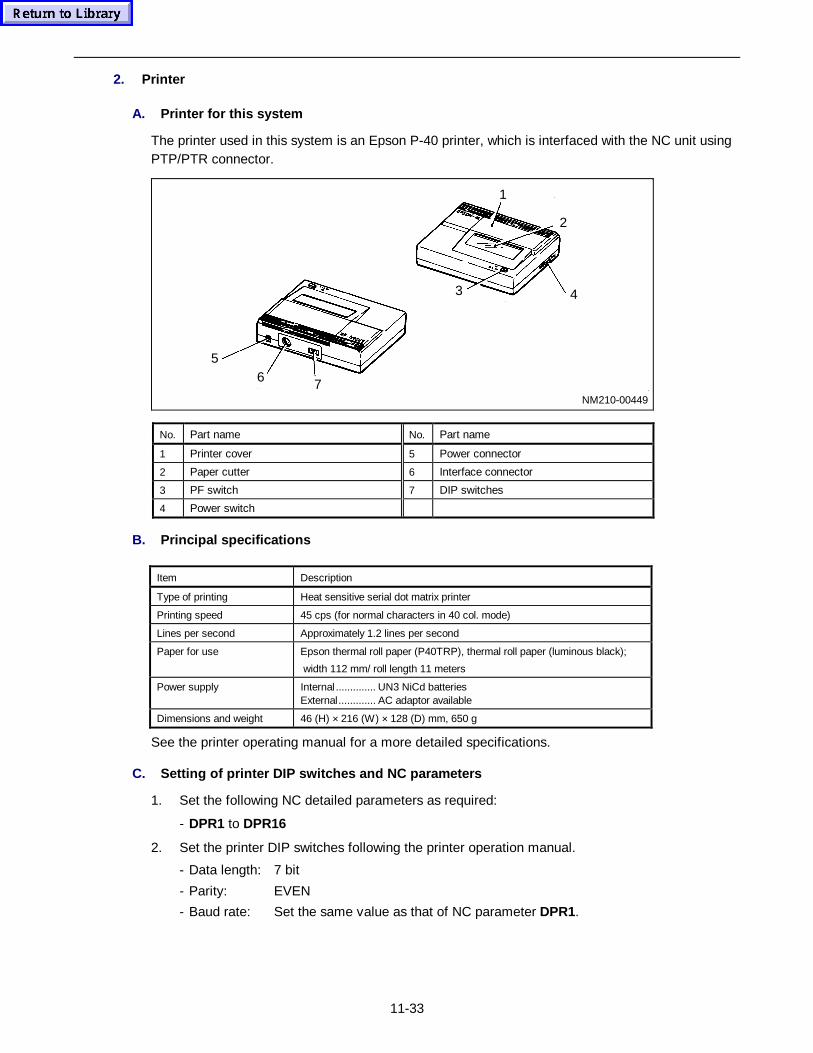
11-33
2. Printer
A. Printer for this system
The printer used in this system is an Epson P-40 printer, which is interfaced with the NC unit usingPTP/PTR connector.
NM210-0044976
2
1
3 4
5
No. Part name No. Part name
1 Printer cover 5 Power connector
2 Paper cutter 6 Interface connector
3 PF switch 7 DIP switches
4 Power switch
B. Principal specifications
Item Description
Type of printing Heat sensitive serial dot matrix printer
Printing speed 45 cps (for normal characters in 40 col. mode)
Lines per second Approximately 1.2 lines per second
Paper for use Epson thermal roll paper (P40TRP), thermal roll paper (luminous black);
width 112 mm/ roll length 11 meters
Power supply Internal .............. UN3 NiCd batteriesExternal............. AC adaptor available
Dimensions and weight 46 (H) × 216 (W) × 128 (D) mm, 650 g
See the printer operating manual for a more detailed specifications.
C. Setting of printer DIP switches and NC p arameters
1. Set the following NC detailed parameters as required:
- DPR1 to DPR16
2. Set the printer DIP switches following the printer operation manual.
- Data length: 7 bit
- Parity: EVEN
- Baud rate: Set the same value as that of NC parameter DPR1.
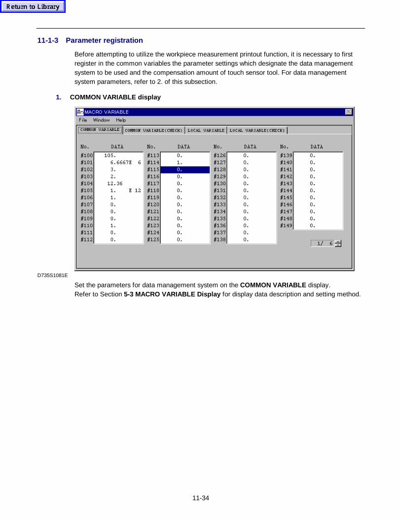
11-34
11-1-3 Parameter registration
Before attempting to utilize the workpiece measurement printout function, it is necessary to firstregister in the common variables the parameter settings which designate the data managementsystem to be used and the compensation amount of touch sensor tool. For data managementsystem parameters, refer to 2. of this subsection.
1. COMMON VARIABLE display
D735S1081E
Set the parameters for data management system on the COMMON VARIABLE display.Refer to Section 5-3 MACRO VARIABLE Display for display data description and setting method.
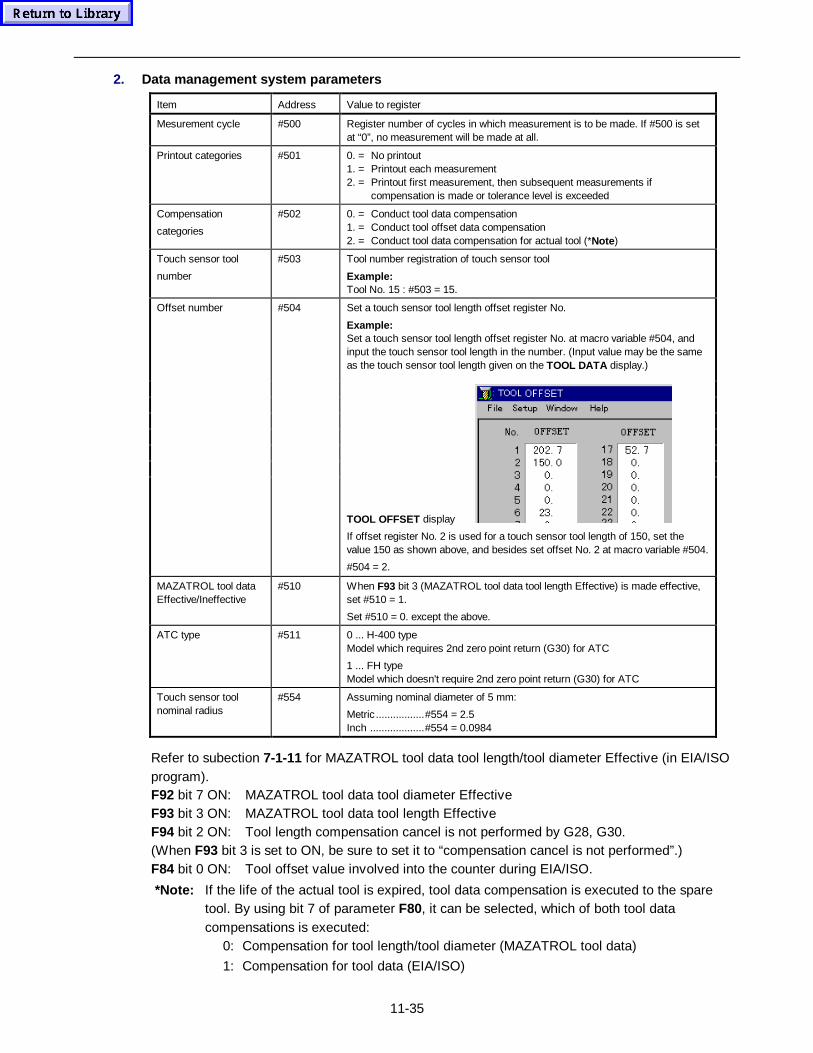
11-35
2. Data management system parameters
Item Address Value to register
Mesurement cycle #500 Register number of cycles in which measurement is to be made. If #500 is setat “0”, no measurement will be made at all.
Printout categories #501 0. = No printout1. = Printout each measurement2. = Printout first measurement, then subsequent measurements if
compensation is made or tolerance level is exceeded
Compensation
categories
#502 0. = Conduct tool data compensation1. = Conduct tool offset data compensation2. = Conduct tool data compensation for actual tool (*Note)
Touch sensor tool
number
#503 Tool number registration of touch sensor tool
Example:Tool No. 15 : #503 = 15.
Set a touch sensor tool length offset register No.
Example:Set a touch sensor tool length offset register No. at macro variable #504, andinput the touch sensor tool length in the number. (Input value may be the sameas the touch sensor tool length given on the TOOL DATA display.)
Offset number #504
TOOL OFFSET display
If offset register No. 2 is used for a touch sensor tool length of 150, set thevalue 150 as shown above, and besides set offset No. 2 at macro variable #504.
#504 = 2.
MAZATROL tool dataEffective/Ineffective
#510 When F93 bit 3 (MAZATROL tool data tool length Effective) is made effective,set #510 = 1.
Set #510 = 0. except the above.
ATC type #511 0 ... H-400 typeModel which requires 2nd zero point return (G30) for ATC
1 ... FH typeModel which doesn't require 2nd zero point return (G30) for ATC
Touch sensor toolnominal radius
#554 Assuming nominal diameter of 5 mm:
Metric .................#554 = 2.5Inch ...................#554 = 0.0984
Refer to subection 7-1-11 for MAZATROL tool data tool length/tool diameter Effective (in EIA/ISOprogram).F92 bit 7 ON: MAZATROL tool data tool diameter EffectiveF93 bit 3 ON: MAZATROL tool data tool length EffectiveF94 bit 2 ON: Tool length compensation cancel is not performed by G28, G30.(When F93 bit 3 is set to ON, be sure to set it to “compensation cancel is not performed”.)F84 bit 0 ON: Tool offset value involved into the counter during EIA/ISO.
*Note: If the life of the actual tool is expired, tool data compensation is executed to the sparetool. By using bit 7 of parameter F80, it can be selected, which of both tool datacompensations is executed:
0: Compensation for tool length/tool diameter (MAZATROL tool data)
1: Compensation for tool data (EIA/ISO)
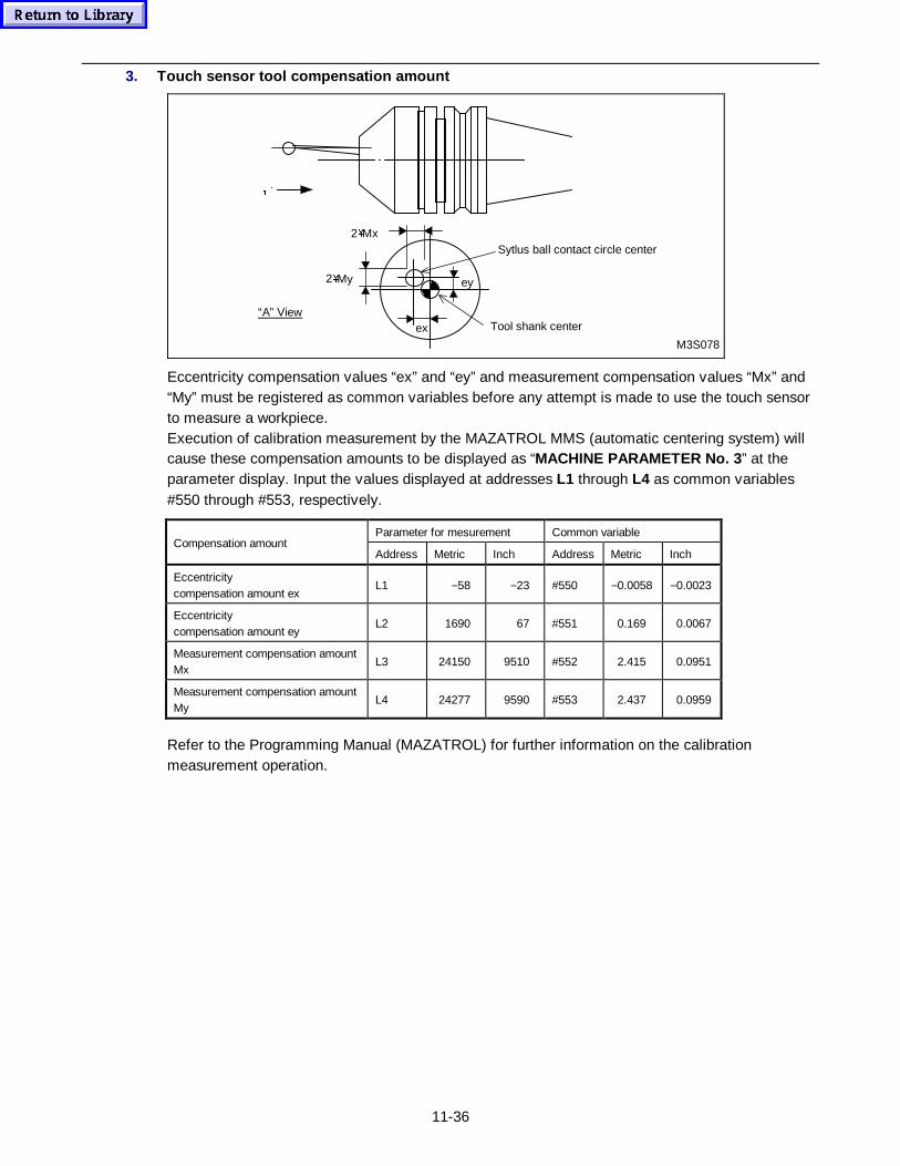
11-36
3. Touch sensor tool compensation amount
M3S078
Tool shank center
Sytlus ball contact circle center
2�My
ex
ey
2�Mx
“A” View
ÄC
Eccentricity compensation values “ex” and “ey” and measurement compensation values “Mx” and“My” must be registered as common variables before any attempt is made to use the touch sensorto measure a workpiece.Execution of calibration measurement by the MAZATROL MMS (automatic centering system) willcause these compensation amounts to be displayed as “MACHINE PARAMETER No. 3 ” at theparameter display. Input the values displayed at addresses L1 through L4 as common variables#550 through #553, respectively.
Parameter for mesurement Common variableCompensation amount
Address Metric Inch Address Metric Inch
Eccentricitycompensation amount ex
L1 −58 −23 #550 −0.0058 −0.0023
Eccentricitycompensation amount ey
L2 1690 67 #551 0.169 0.0067
Measurement compensation amountMx
L3 24150 9510 #552 2.415 0.0951
Measurement compensation amountMy
L4 24277 9590 #553 2.437 0.0959
Refer to the Programming Manual (MAZATROL) for further information on the calibrationmeasurement operation.
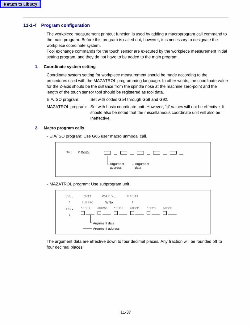
11-37
11-1-4 Program configuration
The workpiece measurement printout function is used by adding a macroprogram call command tothe main program. Before this program is called out, however, it is necessary to designate theworkpiece coordinate system.Tool exchange commands for the touch sensor are executed by the workpiece measurement initialsetting program, and they do not have to be added to the main program.
1. Coordinate system setting
Coordinate system setting for workpiece measurement should be made according to theprocedures used with the MAZATROL programming language. In other words, the coordinate valuefor the Z-axis should be the distance from the spindle nose at the machine zero-point and thelength of the touch sensor tool should be registered as tool data.
EIA/ISO program: Set with codes G54 through G59 and G92.
MAZATROL program: Set with basic coordinate unit. However, “φ” values will not be effective. Itshould also be noted that the miscellaneous coordinate unit will also beineffective.
2. Macro program calls
- EIA/ISO program: Use G65 user macro unmodal call.
G65 P WNo.
Argumentaddress
Argumentdata
- MAZATROL program: Use subprogram unit.
UNo.
∗
SNo.
1
ARGM1 ARGM2 ARGM3 ARGM4 ARGM5
Argument address
Argument data
UNIT
SUBPRO
WORK No.
WNo.
REPEAT
1
ARGM6
The argument data are effective down to four decimal places. Any fraction will be rounded off tofour decimal places.
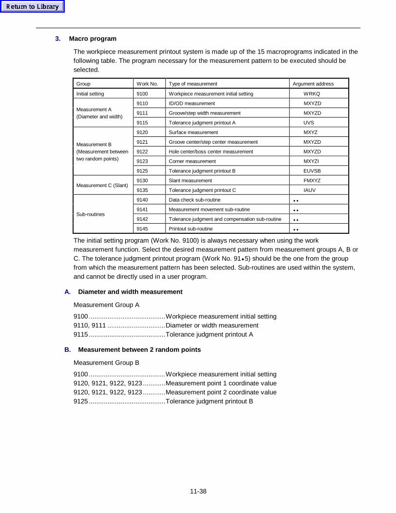
11-38
3. Macro program
The workpiece measurement printout system is made up of the 15 macroprograms indicated in thefollowing table. The program necessary for the measurement pattern to be executed should beselected.
Group Work No. Type of measurement Argument address
Initial setting 9100 Workpiece measurement initial setting WRKQ
9110 ID/OD measurement MXYZD
9111 Groove/step width measurement MXYZDMeasurement A(Diameter and width)
9115 Tolerance judgment printout A UVS
9120 Surface measurement MXYZ
9121 Groove center/step center measurement MXYZD
9122 Hole center/boss center measurement MXYZD
9123 Corner measurement MXYZI
Measurement B(Measurement betweentwo random points)
9125 Tolerance judgment printout B EUVSB
9130 Slant measurement FMXYZMeasurement C (Slant)
9135 Tolerance judgment printout C IAUV
9140 Data check sub-routine ••
9141 Measurement movement sub-routine ••
9142 Tolerance judgment and compensation sub-routine ••Sub-routines
9145 Printout sub-routine ••
The initial setting program (Work No. 9100) is always necessary when using the workmeasurement function. Select the desired measurement pattern from measurement groups A, B orC. The tolerance judgment printout program (Work No. 91• 5) should be the one from the groupfrom which the measurement pattern has been selected. Sub-routines are used within the system,and cannot be directly used in a user program.
A. Diameter and width measurement
Measurement Group A
9100 .........................................Workpiece measurement initial setting9110, 9111 ...............................Diameter or width measurement9115 .........................................Tolerance judgment printout A
B. Measurement between 2 ra ndom points
Measurement Group B
9100 .........................................Workpiece measurement initial setting9120, 9121, 9122, 9123 ............Measurement point 1 coordinate value9120, 9121, 9122, 9123 ............Measurement point 2 coordinate value9125 .........................................Tolerance judgment printout B
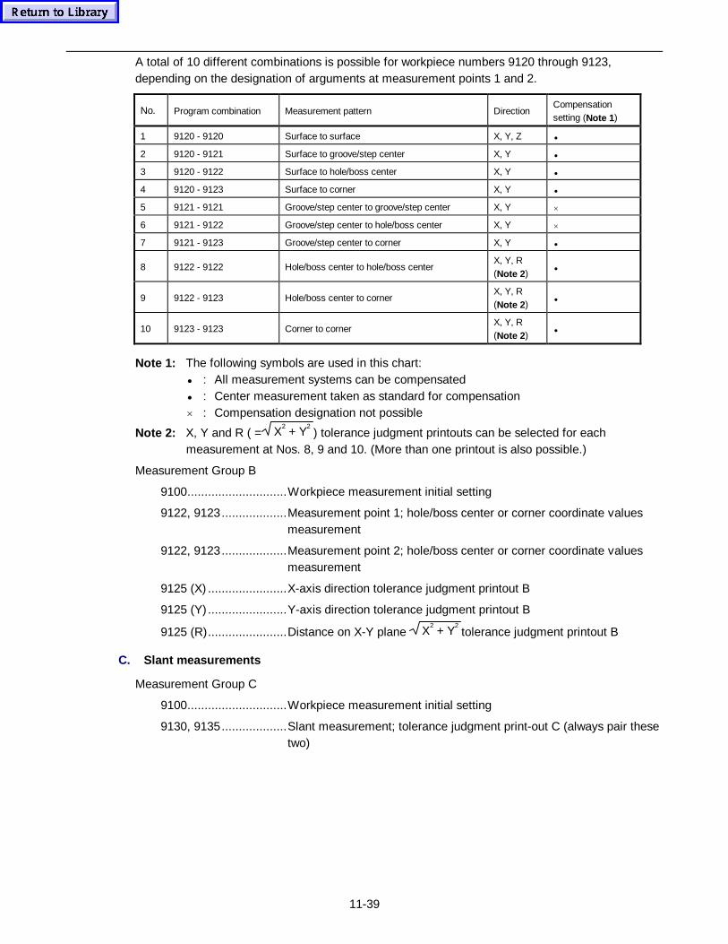
11-39
A total of 10 different combinations is possible for workpiece numbers 9120 through 9123,depending on the designation of arguments at measurement points 1 and 2.
No. Program combination Measurement pattern DirectionCompensationsetting (Note 1 )
1 9120 - 9120 Surface to surface X, Y, Z •
2 9120 - 9121 Surface to groove/step center X, Y •
3 9120 - 9122 Surface to hole/boss center X, Y •
4 9120 - 9123 Surface to corner X, Y •
5 9121 - 9121 Groove/step center to groove/step center X, Y ×
6 9121 - 9122 Groove/step center to hole/boss center X, Y ×
7 9121 - 9123 Groove/step center to corner X, Y •
8 9122 - 9122 Hole/boss center to hole/boss centerX, Y, R(Note 2 )
•
9 9122 - 9123 Hole/boss center to cornerX, Y, R(Note 2 )
•
10 9123 - 9123 Corner to cornerX, Y, R(Note 2 )
•
Note 1: The following symbols are used in this chart:• : All measurement systems can be compensated• : Center measurement taken as standard for compensation× : Compensation designation not possible
Note 2: X, Y and R ( = X2 + Y
2) tolerance judgment printouts can be selected for each
measurement at Nos. 8, 9 and 10. (More than one printout is also possible.)
Measurement Group B
9100.............................Workpiece measurement initial setting
9122, 9123...................Measurement point 1; hole/boss center or corner coordinate valuesmeasurement
9122, 9123...................Measurement point 2; hole/boss center or corner coordinate valuesmeasurement
9125 (X) .......................X-axis direction tolerance judgment printout B
9125 (Y) .......................Y-axis direction tolerance judgment printout B
9125 (R).......................Distance on X-Y plane X2 + Y
2tolerance judgment printout B
C. Slant measurements
Measurement Group C
9100.............................Workpiece measurement initial setting
9130, 9135...................Slant measurement; tolerance judgment print-out C (always pair thesetwo)
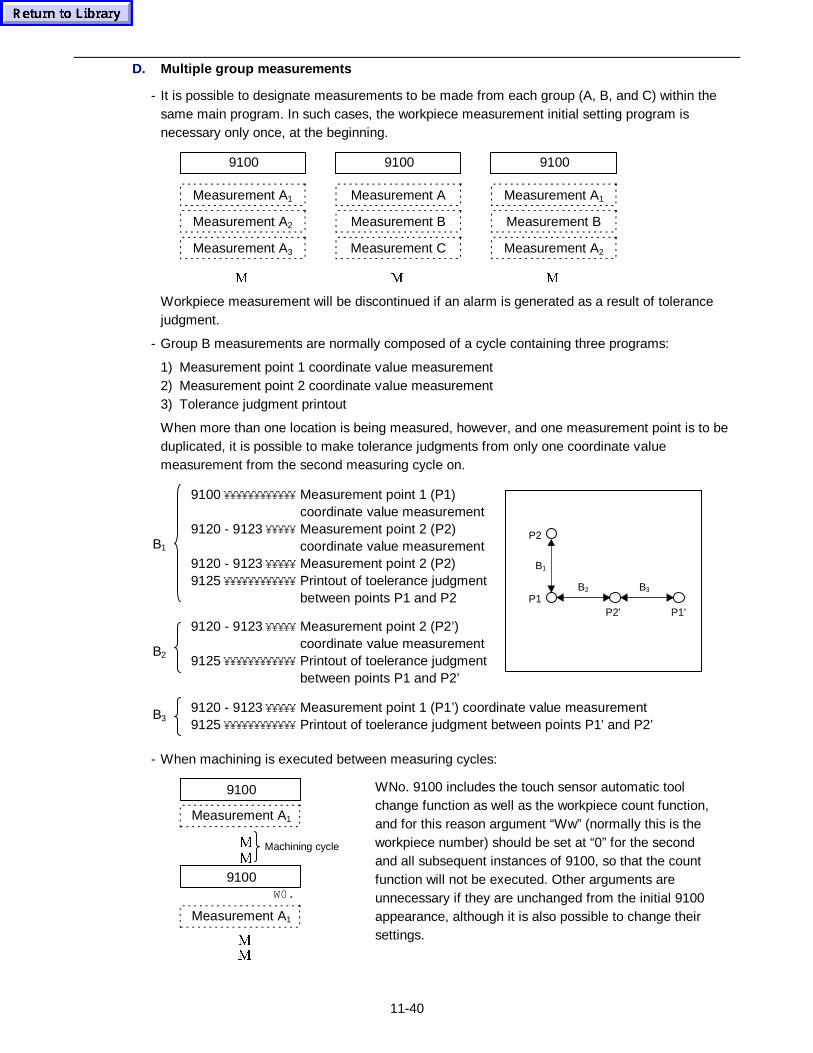
11-40
D. Multiple group measurements
- It is possible to designate measurements to be made from each group (A, B, and C) within thesame main program. In such cases, the workpiece measurement initial setting program isnecessary only once, at the beginning.
9100
Measurement A1
Measurement A2
Measurement A3
0
9100
Measurement A
Measurement B
Measurement C
0
9100
Measurement A1
Measurement B
Measurement A2
0
Workpiece measurement will be discontinued if an alarm is generated as a result of tolerancejudgment.
- Group B measurements are normally composed of a cycle containing three programs:
1) Measurement point 1 coordinate value measurement2) Measurement point 2 coordinate value measurement3) Tolerance judgment printout
When more than one location is being measured, however, and one measurement point is to beduplicated, it is possible to make tolerance judgments from only one coordinate valuemeasurement from the second measuring cycle on.
B1
9120 - 9123 ¥¥¥¥¥ Measurement point 1 (P1’) coordinate value measurement9125 ¥¥¥¥¥¥¥¥¥¥¥¥ Printout of toelerance judgment between points P1’ and P2’
9120 - 9123 ¥¥¥¥¥ Measurement point 2 (P2’)coordinate value measurement
9125 ¥¥¥¥¥¥¥¥¥¥¥¥ Printout of toelerance judgmentbetween points P1 and P2’
9100 ¥¥¥¥¥¥¥¥¥¥¥¥ Measurement point 1 (P1)coordinate value measurement
9120 - 9123 ¥¥¥¥¥ Measurement point 2 (P2)coordinate value measurement
9120 - 9123 ¥¥¥¥¥ Measurement point 2 (P2)9125 ¥¥¥¥¥¥¥¥¥¥¥¥ Printout of toelerance judgment
between points P1 and P2
B2
B3
B3B2
B1
P2
P1P2’ P1’
- When machining is executed between measuring cycles:
0
0
0
0
9100
Measurement A1
Machining cycle
W0.
9100
Measurement A1
WNo. 9100 includes the touch sensor automatic toolchange function as well as the workpiece count function,and for this reason argument “Ww” (normally this is theworkpiece number) should be set at “0” for the secondand all subsequent instances of 9100, so that the countfunction will not be executed. Other arguments areunnecessary if they are unchanged from the initial 9100appearance, although it is also possible to change theirsettings.
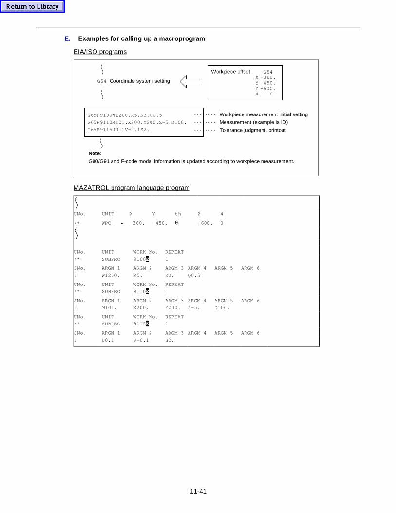
11-41
E. Examples for calling up a macroprogram
EIA/ISO programs
G54 Coordinate system setting
Workpiece offset G54X -360.Y –450.Z -600.4 0
G65P9100W1200.R5.K3.Q0.5
G65P9110M101.X200.Y200.Z-5.D100.
G65P9115U0.1V-0.1S2.
Workpiece measurement initial setting
Measurement (example is ID)
Tolerance judgment, printout
Note:
G90/G91 and F-code modal information is updated according to workpiece measurement.
MAZATROL program language program
UNo. UNIT X Y th Z 4
** WPC - • –360. –450. θ0 –600. 0
UNo. UNIT WORK No. REPEAT
** SUBPRO 9100E 1
SNo. ARGM 1 ARGM 2 ARGM 3 ARGM 4 ARGM 5 ARGM 6
1 W1200. R5. K3. Q0.5
UNo. UNIT WORK No. REPEAT
** SUBPRO 9110E 1
SNo. ARGM 1 ARGM 2 ARGM 3 ARGM 4 ARGM 5 ARGM 6
1 M101. X200. Y200. Z-5. D100.
UNo. UNIT WORK No. REPEAT
** SUBPRO 9115E 1
SNo. ARGM 1 ARGM 2 ARGM 3 ARGM 4 ARGM 5 ARGM 6
1 U0.1 V-0.1 S2.
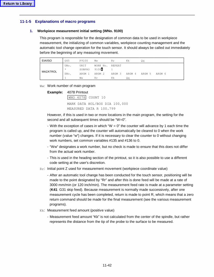
11-42
11-1-5 Explanations of macro programs
1. Workpiece measurement initial setting (WNo. 9100)
This program is responsible for the designation of common data to be used in workpiecemeasurement, the initializing of common variables, workpiece counting management and theautomatic tool change operation for the touch sensor. It should always be called out immediatelybefore the beginning of any measuring movement.
EIA/ISO G65 P9100 Ww Rr Kk Qq
UNo. UNIT WORK No. REPEAT
* SUBPRO 9100E 1
SNo. ARGM 1 ARGM 2 ARGM 3 ARGM 4 ARGM 5 ARGM 6MAZATROL
1 Ww Rr Kk Qq
Ww: Work number of main program
Example: 4078 PrintoutWNO 4078 COUNT 10
MARK DATA HOL/BOS DIA 100,000
MEASURED DATA R 100.799
However, if this is used in two or more locations in the main program, the setting for thesecond and all subsequent times should be “W=0”.
- With the exception of cases in which “W = 0” the counter will advance by 1 each time theprogram is called up, and the counter will automatically be cleared to 0 when the worknumber (value “w”) changes. If it is necessary to clear the counter to 0 without changingwork numbers, set common variables #135 and #136 to 0.
- “Ww” designates a work number, but no check is made to ensure that this does not differfrom the actual work number.
- This is used in the heading section of the printout, so it is also possible to use a differentcode setting at the user's discretion.
Rr : Initial point Z used for measurement movement (workpiece coordinate value)
- After an automatic tool change has been conducted for the touch sensor, positioning will bemade to the point designated by “Rr” and after this is done feed will be made at a rate of3000 mm/min (or 120 inch/min). The measurement feed rate is made at a parameter setting(K41: G31 skip feed). Because measurement is normally made successively, after onemeasurement cycle has been completed, return is made to point R, which means that a zeroreturn command should be made for the final measurement (see the various measurementprograms).
Kk: Measurement feed amount (positive value)
- Measurement feed amount “Kk” is not calculated from the center of the spindle, but ratherrepresents the distance from the tip of the probe to the surface to be measured.
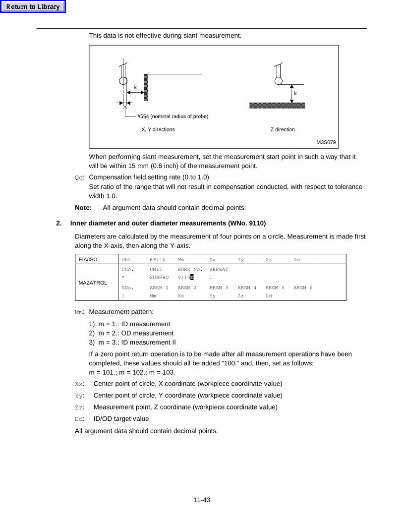
11-43
This data is not effective during slant measurement.
M3S079
kk
#554 (nominal radius of probe)
X, Y directions Z direction
When performing slant measurement, set the measurement start point in such a way that itwill be within 15 mm (0.6 inch) of the measurement point.
Qq: Compensation field setting rate (0 to 1.0)
Set ratio of the range that will not result in compensation conducted, with respect to tolerancewidth 1.0.
Note: All argument data should contain decimal points.
2. Inner diameter and outer diameter measurements (WNo. 9110)
Diameters are calculated by the measurement of four points on a circle. Measurement is made firstalong the X-axis, then along the Y-axis.
EIA/ISO G65 P9110 Mm Xx Yy Zz Dd
UNo. UNIT WORK No. REPEAT
* SUBPRO 9110E 1
SNo. ARGM 1 ARGM 2 ARGM 3 ARGM 4 ARGM 5 ARGM 6MAZATROL
1 Mm Xx Yy Zz Dd
Mm: Measurement pattern:
1) m = 1.: ID measurement2) m = 2.: OD measurement3) m = 3.: ID measurement II
If a zero point return operation is to be made after all measurement operations have beencompleted, these values should all be added “100.” and, then, set as follows:m = 101.; m = 102.; m = 103.
Xx: Center point of circle, X coordinate (workpiece coordinate value)
Yy: Center point of circle, Y coordinate (workpiece coordinate value)
Zz : Measurement point, Z coordinate (workpiece coordinate value)
Dd: ID/OD target value
All argument data should contain decimal points.
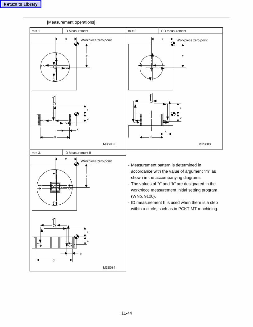
11-44
[Measurement operations]
m = 1. ID Measurement m = 2. OD measurement
x
y
Workpiece zero point
r
z
k
d
M3S082
x
y
k
d
z
r
M3S083
Workpiece zero point
m = 3. ID Measurement II
r
z
k
x
y
d
M3S084
Workpiece zero point- Measurement pattern is determined in
accordance with the value of argument “m” as
shown in the accompanying diagrams.
- The values of “r” and “k” are designated in the
workpiece measurement initial setting program
(WNo. 9100).
- ID measurement II is used when there is a step
within a circle, such as in PCKT MT machining.
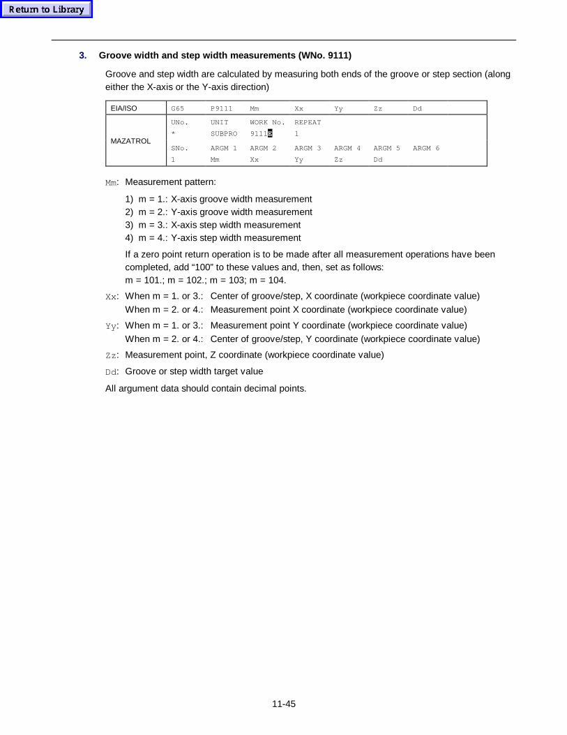
11-45
3. Groove width and step width measurements (WNo. 9111)
Groove and step width are calculated by measuring both ends of the groove or step section (alongeither the X-axis or the Y-axis direction)
EIA/ISO G65 P9111 Mm Xx Yy Zz Dd
UNo. UNIT WORK No. REPEAT
* SUBPRO 9111E 1
SNo. ARGM 1 ARGM 2 ARGM 3 ARGM 4 ARGM 5 ARGM 6MAZATROL
1 Mm Xx Yy Zz Dd
Mm: Measurement pattern:
1) m = 1.: X-axis groove width measurement2) m = 2.: Y-axis groove width measurement3) m = 3.: X-axis step width measurement4) m = 4.: Y-axis step width measurement
If a zero point return operation is to be made after all measurement operations have beencompleted, add “100” to these values and, then, set as follows:m = 101.; m = 102.; m = 103; m = 104.
Xx: When m = 1. or 3.: Center of groove/step, X coordinate (workpiece coordinate value)
When m = 2. or 4.: Measurement point X coordinate (workpiece coordinate value)
Yy: When m = 1. or 3.: Measurement point Y coordinate (workpiece coordinate value)
When m = 2. or 4.: Center of groove/step, Y coordinate (workpiece coordinate value)
Zz : Measurement point, Z coordinate (workpiece coordinate value)
Dd: Groove or step width target value
All argument data should contain decimal points.
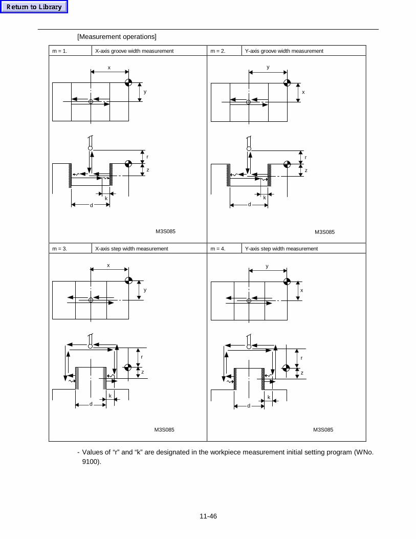
11-46
[Measurement operations]
m = 1. X-axis groove width measurement m = 2. Y-axis groove width measurement
x
y
k
z
d
r
M3S085 M3S085
x
y
k
z
d
r
m = 3. X-axis step width measurement m = 4. Y-axis step width measurement
x
y
k
z
r
d
M3S085
x
y
k
z
r
d
M3S085
- Values of “r” and “k” are designated in the workpiece measurement initial setting program (WNo.9100).
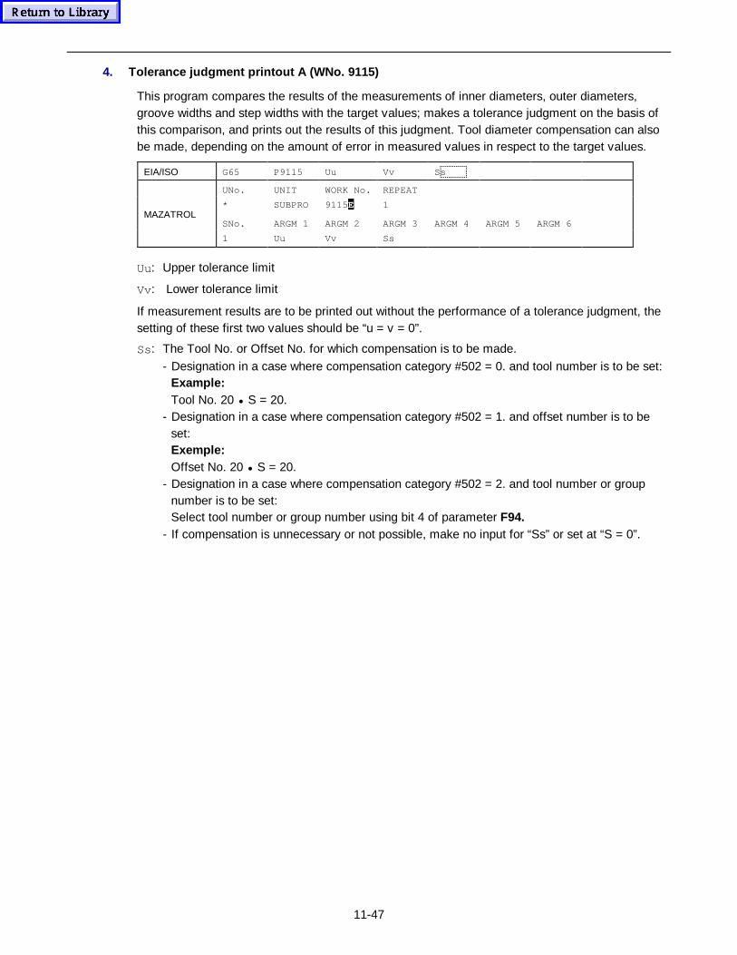
11-47
4. Tolerance judgment printout A (WNo. 9115)
This program compares the results of the measurements of inner diameters, outer diameters,groove widths and step widths with the target values; makes a tolerance judgment on the basis ofthis comparison, and prints out the results of this judgment. Tool diameter compensation can alsobe made, depending on the amount of error in measured values in respect to the target values.
EIA/ISO G65 P9115 Uu Vv Ss
UNo. UNIT WORK No. REPEAT
* SUBPRO 9115E 1
SNo. ARGM 1 ARGM 2 ARGM 3 ARGM 4 ARGM 5 ARGM 6MAZATROL
1 Uu Vv Ss
Uu: Upper tolerance limit
Vv: Lower tolerance limit
If measurement results are to be printed out without the performance of a tolerance judgment, thesetting of these first two values should be “u = v = 0”.
Ss: The Tool No. or Offset No. for which compensation is to be made.
- Designation in a case where compensation category #502 = 0. and tool number is to be set:Example:Tool No. 20 • S = 20.
- Designation in a case where compensation category #502 = 1. and offset number is to beset:Exemple:Offset No. 20 • S = 20.
- Designation in a case where compensation category #502 = 2. and tool number or groupnumber is to be set:Select tool number or group number using bit 4 of parameter F94.
- If compensation is unnecessary or not possible, make no input for “Ss” or set at “S = 0”.
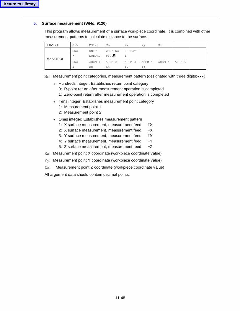
11-48
5. Surface measurement (WNo. 9120)
This program allows measurement of a surface workpiece coordinate. It is combined with othermeasurement patterns to calculate distance to the surface.
EIA/ISO G65 P9120 Mm Xx Yy Zz
UNo. UNIT WORK No. REPEAT
* SUBPRO 9120E 1
SNo. ARGM 1 ARGM 2 ARGM 3 ARGM 4 ARGM 5 ARGM 6MAZATROL
1 Mm Xx Yy Zz
Mm: Measurement point categories, measurement pattern (designated with three digits:••• ).
• Hundreds integer: Establishes return point category0: R-point return after measurement operation is completed1: Zero-point return after measurement operation is completed
• Tens integer: Establishes measurement point category1: Measurement point 12: Measurement point 2
• Ones integer: Establishes measurement pattern1: X surface measurement, measurement feed +X2: X surface measurement, measurement feed −X3: Y surface measurement, measurement feed +Y4: Y surface measurement, measurement feed −Y5: Z surface measurement, measurement feed −Z
Xx: Measurement point X coordinate (workpiece coordinate value)
Yy: Measurement point Y coordinate (workpiece coordinate value)
Zz : Measurement point Z coordinate (workpiece coordinate value)
All argument data should contain decimal points.
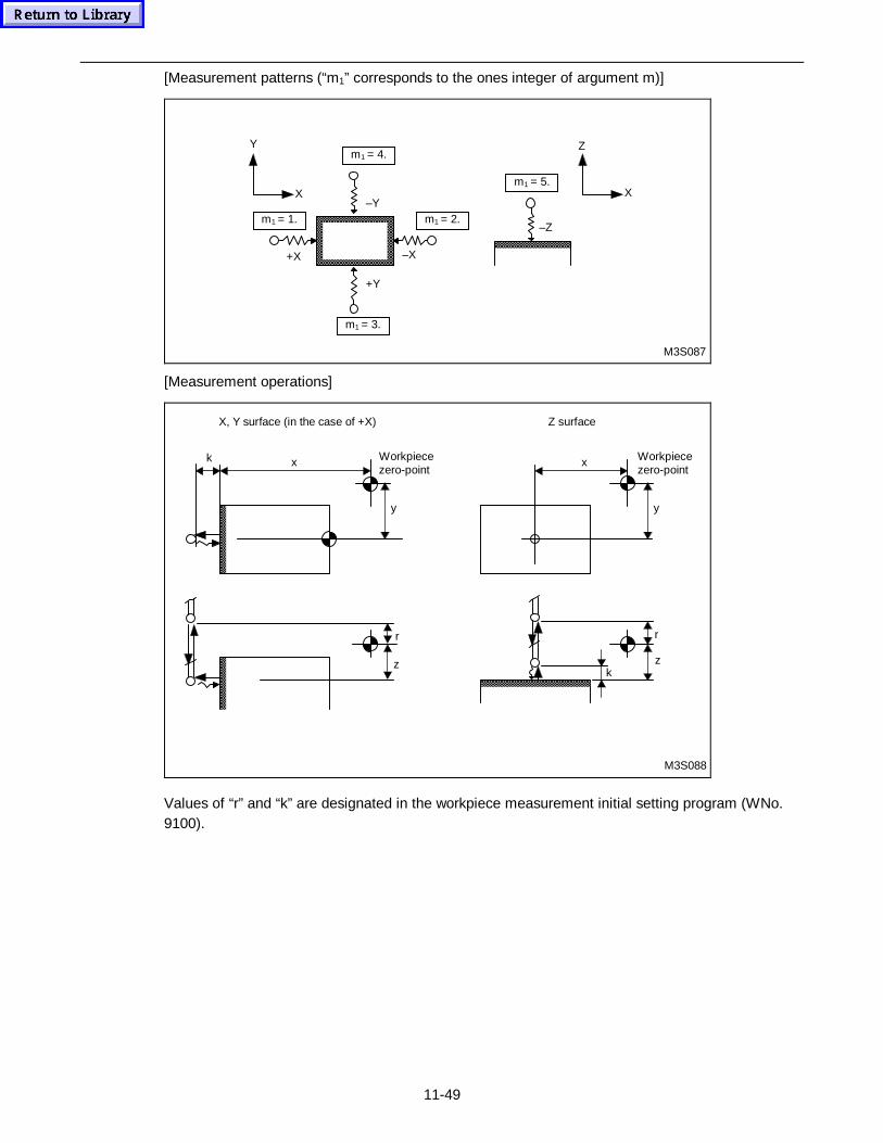
11-49
[Measurement patterns (“m1” corresponds to the ones integer of argument m)]
M3S087
m1 = 3.
+Y
m1 = 4.
m1 = 2.–Y
–X
m1 = 1.
+X
Y
X
–Z
m1 = 5.
Z
X
[Measurement operations]
M3S088
x
y
k Workpiecezero-point
Workpiecezero-point
x
y
Z surfaceX, Y surface (in the case of +X)
r
z z
r
k
Values of “r” and “k” are designated in the workpiece measurement initial setting program (WNo.9100).
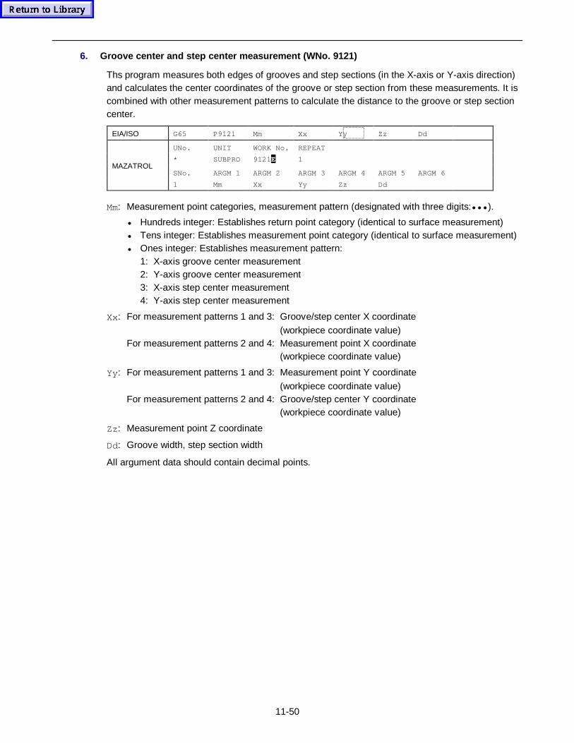
11-50
6. Groove center and step center measurement (WNo. 9121)
Ths program measures both edges of grooves and step sections (in the X-axis or Y-axis direction)and calculates the center coordinates of the groove or step section from these measurements. It iscombined with other measurement patterns to calculate the distance to the groove or step sectioncenter.
EIA/ISO G65 P9121 Mm Xx Yy Zz Dd
UNo. UNIT WORK No. REPEAT
* SUBPRO 9121E 1
SNo. ARGM 1 ARGM 2 ARGM 3 ARGM 4 ARGM 5 ARGM 6MAZATROL
1 Mm Xx Yy Zz Dd
Mm: Measurement point categories, measurement pattern (designated with three digits:••• ).
• Hundreds integer: Establishes return point category (identical to surface measurement)• Tens integer: Establishes measurement point category (identical to surface measurement)• Ones integer: Establishes measurement pattern:
1: X-axis groove center measurement2: Y-axis groove center measurement3: X-axis step center measurement4: Y-axis step center measurement
Xx: For measurement patterns 1 and 3: Groove/step center X coordinate
(workpiece coordinate value)For measurement patterns 2 and 4: Measurement point X coordinate
(workpiece coordinate value)
Yy: For measurement patterns 1 and 3: Measurement point Y coordinate
(workpiece coordinate value)For measurement patterns 2 and 4: Groove/step center Y coordinate
(workpiece coordinate value)
Zz : Measurement point Z coordinate
Dd: Groove width, step section width
All argument data should contain decimal points.
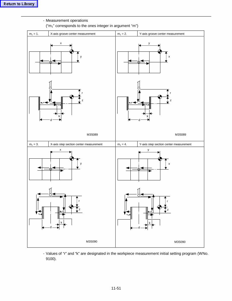
11-51
- Measurement operations(“m1” corresponds to the ones integer in argument “m”)
m1 = 1. X-axis groove center measurement m1 = 2. Y-axis groove center measurement
x
y
k
z
d
r
M3S089
y
x
k
z
d
r
M3S089
m1 = 3. X-axis step section center measurement m1 = 4. Y-axis step section center measurement
x
y
k
z
r
d
M3S090
y
x
k
z
r
d
M3S090
- Values of “r” and “k” are designated in the workpiece measurement initial setting program (WNo.9100).
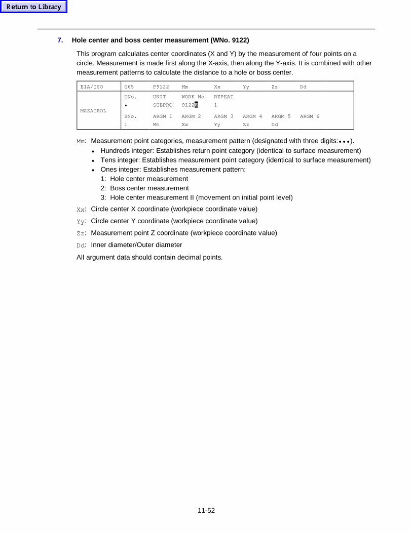
11-52
7. Hole center and boss center measurement (WNo. 9122)
This program calculates center coordinates (X and Y) by the measurement of four points on acircle. Measurement is made first along the X-axis, then along the Y-axis. It is combined with othermeasurement patterns to calculate the distance to a hole or boss center.
EIA/ISO G65 P9122 Mm Xx Yy Zz Dd
UNo. UNIT WORK No. REPEAT
• SUBPRO 9122E 1
SNo. ARGM 1 ARGM 2 ARGM 3 ARGM 4 ARGM 5 ARGM 6MAZATROL
1 Mm Xx Yy Zz Dd
Mm: Measurement point categories, measurement pattern (designated with three digits:••• ).
• Hundreds integer: Establishes return point category (identical to surface measurement)• Tens integer: Establishes measurement point category (identical to surface measurement)• Ones integer: Establishes measurement pattern:
1: Hole center measurement2: Boss center measurement3: Hole center measurement II (movement on initial point level)
Xx: Circle center X coordinate (workpiece coordinate value)
Yy: Circle center Y coordinate (workpiece coordinate value)
Zz : Measurement point Z coordinate (workpiece coordinate value)
Dd: Inner diameter/Outer diameter
All argument data should contain decimal points.
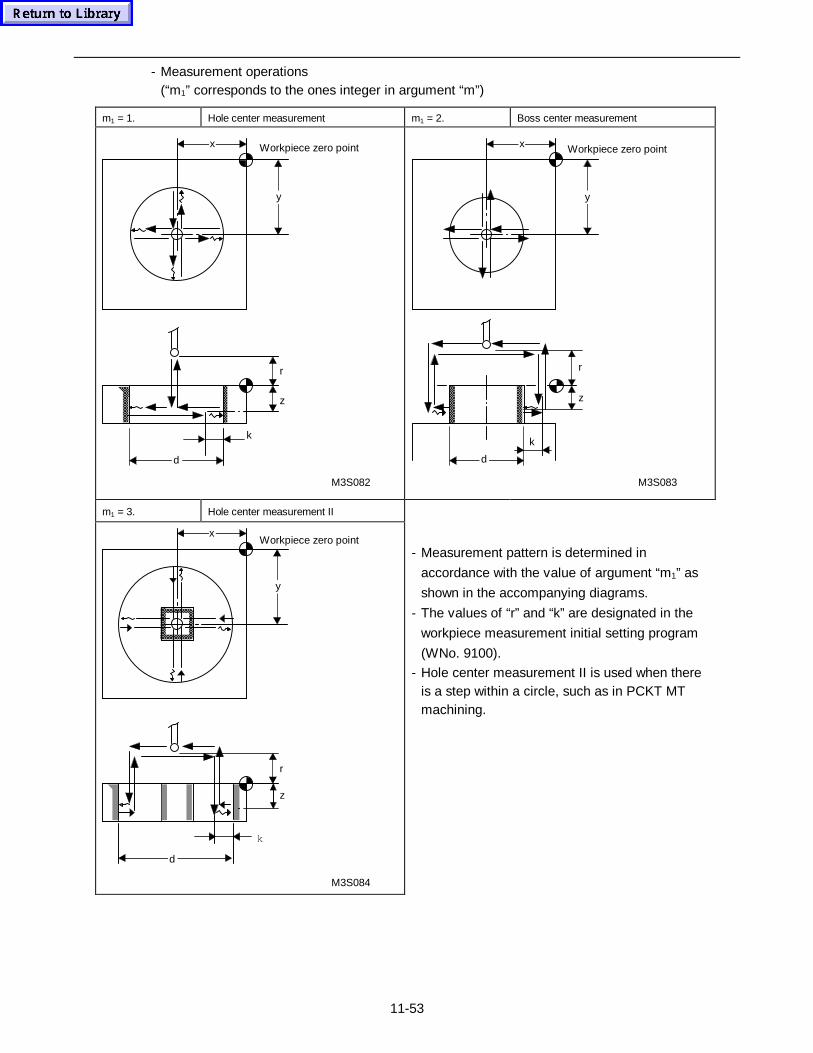
11-53
- Measurement operations(“m1” corresponds to the ones integer in argument “m”)
m1 = 1. Hole center measurement m1 = 2. Boss center measurement
x
y
Workpiece zero point
r
z
k
d
M3S082
x
y
k
d
z
r
M3S083
Workpiece zero point
m1 = 3. Hole center measurement II
r
z
k
x
y
d
M3S084
Workpiece zero point- Measurement pattern is determined in
accordance with the value of argument “m1” as
shown in the accompanying diagrams.
- The values of “r” and “k” are designated in the
workpiece measurement initial setting program
(WNo. 9100).
- Hole center measurement II is used when thereis a step within a circle, such as in PCKT MTmachining.
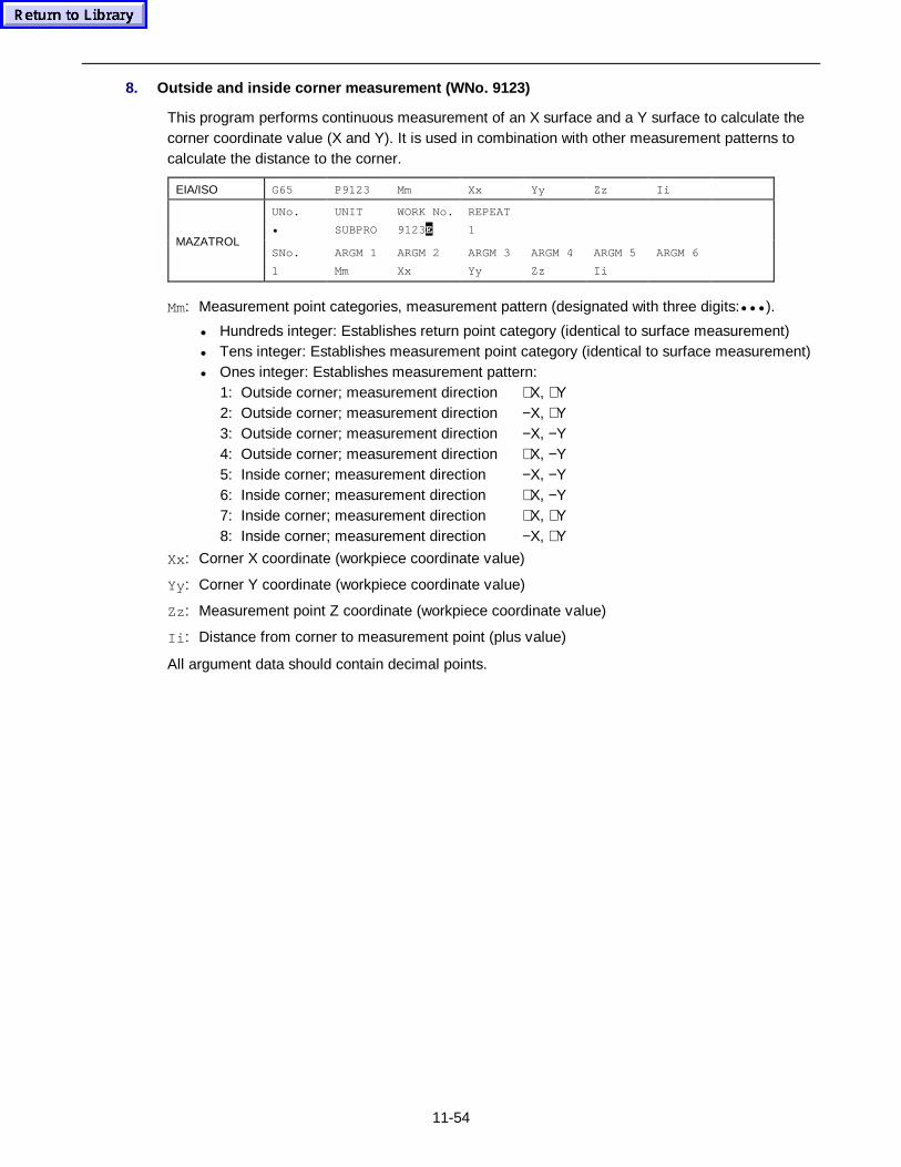
11-54
8. Outside and inside corner measurement (WNo. 9123)
This program performs continuous measurement of an X surface and a Y surface to calculate thecorner coordinate value (X and Y). It is used in combination with other measurement patterns tocalculate the distance to the corner.
EIA/ISO G65 P9123 Mm Xx Yy Zz Ii
UNo. UNIT WORK No. REPEAT
• SUBPRO 9123E 1
SNo. ARGM 1 ARGM 2 ARGM 3 ARGM 4 ARGM 5 ARGM 6MAZATROL
1 Mm Xx Yy Zz Ii
Mm: Measurement point categories, measurement pattern (designated with three digits:••• ).
• Hundreds integer: Establishes return point category (identical to surface measurement)• Tens integer: Establishes measurement point category (identical to surface measurement)• Ones integer: Establishes measurement pattern:
1: Outside corner; measurement direction +X, +Y2: Outside corner; measurement direction −X, +Y3: Outside corner; measurement direction −X, −Y4: Outside corner; measurement direction +X, −Y5: Inside corner; measurement direction −X, −Y6: Inside corner; measurement direction +X, −Y7: Inside corner; measurement direction +X, +Y8: Inside corner; measurement direction −X, +Y
Xx: Corner X coordinate (workpiece coordinate value)
Yy: Corner Y coordinate (workpiece coordinate value)
Zz : Measurement point Z coordinate (workpiece coordinate value)
Ii : Distance from corner to measurement point (plus value)
All argument data should contain decimal points.
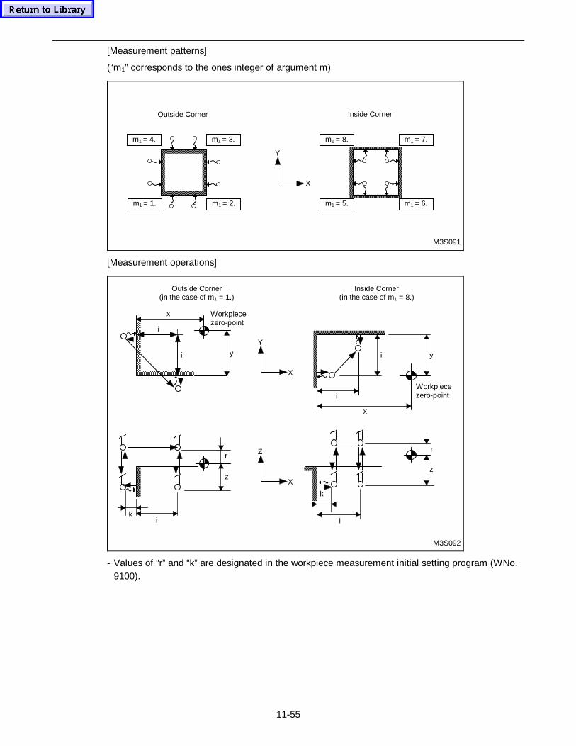
11-55
[Measurement patterns]
(“m1” corresponds to the ones integer of argument m)
M3S091
m1 = 2.m1 = 1.
m1 = 3.m1 = 4.
Inside CornerOutside Corner
m1 = 7.m1 = 8.
m1 = 6.m1 = 5.
Y
X
[Measurement operations]
x
y
i
i yi
i
x
Y
X
M3S092
z
r
ki
k
i
z
rZ
X
Workpiecezero-point
Workpiecezero-point
Outside Corner(in the case of m1 = 1.)
Inside Corner(in the case of m1 = 8.)
- Values of “r” and “k” are designated in the workpiece measurement initial setting program (WNo.9100).
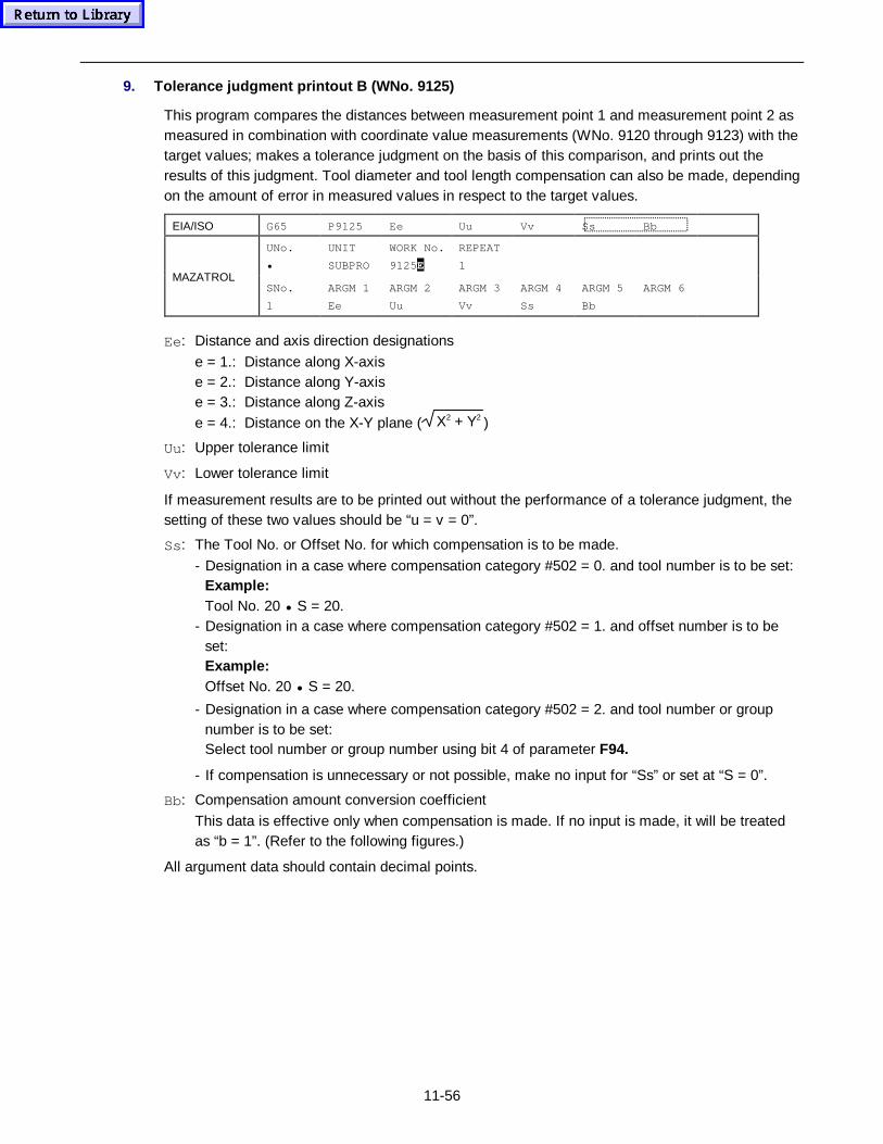
11-56
9. Tolerance judgment printout B (WNo. 9125)
This program compares the distances between measurement point 1 and measurement point 2 asmeasured in combination with coordinate value measurements (WNo. 9120 through 9123) with thetarget values; makes a tolerance judgment on the basis of this comparison, and prints out theresults of this judgment. Tool diameter and tool length compensation can also be made, dependingon the amount of error in measured values in respect to the target values.
EIA/ISO G65 P9125 Ee Uu Vv Ss Bb
UNo. UNIT WORK No. REPEAT
• SUBPRO 9125E 1
SNo. ARGM 1 ARGM 2 ARGM 3 ARGM 4 ARGM 5 ARGM 6MAZATROL
1 Ee Uu Vv Ss Bb
Ee: Distance and axis direction designations
e = 1.: Distance along X-axise = 2.: Distance along Y-axise = 3.: Distance along Z-axise = 4.: Distance on the X-Y plane ( X2 + Y2 )
Uu: Upper tolerance limit
Vv: Lower tolerance limit
If measurement results are to be printed out without the performance of a tolerance judgment, thesetting of these two values should be “u = v = 0”.
Ss: The Tool No. or Offset No. for which compensation is to be made.
- Designation in a case where compensation category #502 = 0. and tool number is to be set:Example:Tool No. 20 • S = 20.
- Designation in a case where compensation category #502 = 1. and offset number is to beset:Example:Offset No. 20 • S = 20.
- Designation in a case where compensation category #502 = 2. and tool number or groupnumber is to be set:Select tool number or group number using bit 4 of parameter F94.
- If compensation is unnecessary or not possible, make no input for “Ss” or set at “S = 0”.
Bb: Compensation amount conversion coefficient
This data is effective only when compensation is made. If no input is made, it will be treatedas “b = 1”. (Refer to the following figures.)
All argument data should contain decimal points.
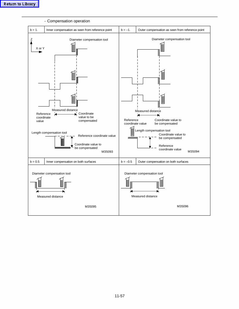
11-57
- Compensation operation
b = 1. Inner compensation as seen from reference point b = –1. Outer compensation as seen from reference point
Z
M3S093
Diameter compensation tool
X or Y
Measured distanceReferencecoordinatevalue
Coordinatevalue to becompensated
Length compensation toolReference coordinate value
Coordinate value tobe compensated
M3S094
Diameter compensation tool
Referencecoordinate value
Coordinate value tobe compensated
Coordinate value tobe compensated
Referencecoordinate value
Length compensation tool
Measured distance
b = 0.5 Inner compensation on both surfaces b = –0.5 Outer compensation on both surfaces
M3S095
Measured distance
Diameter compensation tool
M3S096
Measured distance
Diameter compensation tool
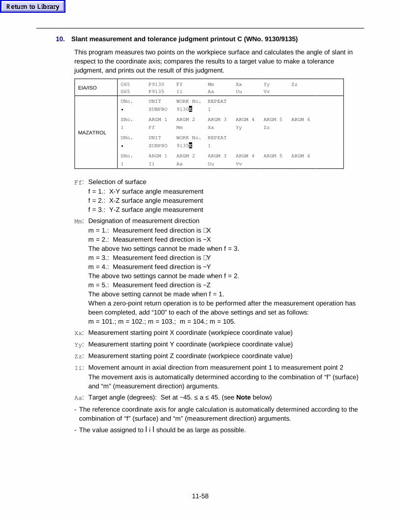
11-58
10. Slant measurement and tolerance judgment printout C (WNo. 9130/9135)
This program measures two points on the workpiece surface and calculates the angle of slant inrespect to the coordinate axis; compares the results to a target value to make a tolerancejudgment, and prints out the result of this judgment.
EIA/ISOG65
G65
P9130
P9135
Ff
Ii
Mm
Aa
Xx
Uu
Yy
Vv
Zz
UNo. UNIT WORK No. REPEAT
• SUBPRO 9130E 1
SNo. ARGM 1 ARGM 2 ARGM 3 ARGM 4 ARGM 5 ARGM 6
1 Ff Mm Xx Yy Zz
UNo. UNIT WORK No. REPEAT
• SUBPRO 9135E 1
SNo. ARGM 1 ARGM 2 ARGM 3 ARGM 4 ARGM 5 ARGM 6
MAZATROL
1 Ii Aa Uu Vv
Ff : Selection of surface
f = 1.: X-Y surface angle measurementf = 2.: X-Z surface angle measurementf = 3.: Y-Z surface angle measurement
Mm: Designation of measurement direction
m = 1.: Measurement feed direction is +Xm = 2.: Measurement feed direction is −XThe above two settings cannot be made when f = 3.m = 3.: Measurement feed direction is +Ym = 4.: Measurement feed direction is −YThe above two settings cannot be made when f = 2.m = 5.: Measurement feed direction is −ZThe above setting cannot be made when f = 1.When a zero-point return operation is to be performed after the measurement operation hasbeen completed, add “100” to each of the above settings and set as follows:m = 101.; m = 102.; m = 103.; m = 104.; m = 105.
Xx: Measurement starting point X coordinate (workpiece coordinate value)
Yy: Measurement starting point Y coordinate (workpiece coordinate value)
Zz : Measurement starting point Z coordinate (workpiece coordinate value)
Ii : Movement amount in axial direction from measurement point 1 to measurement point 2
The movement axis is automatically determined according to the combination of “f” (surface)and “m” (measurement direction) arguments.
Aa: Target angle (degrees): Set at −45. ≤ a ≤ 45. (see Note below)
- The reference coordinate axis for angle calculation is automatically determined according to thecombination of “f” (surface) and “m” (measurement direction) arguments.
- The value assigned to l i l should be as large as possible.
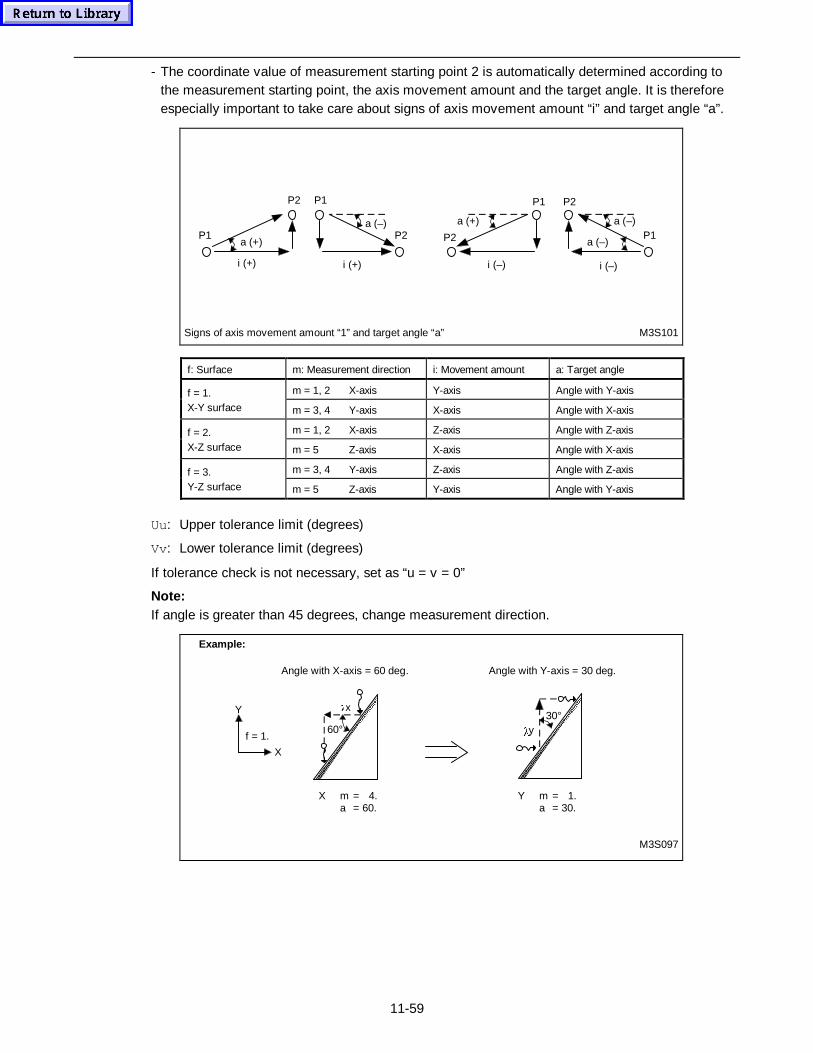
11-59
- The coordinate value of measurement starting point 2 is automatically determined according tothe measurement starting point, the axis movement amount and the target angle. It is thereforeespecially important to take care about signs of axis movement amount “i” and target angle “a”.
a (+)P1
P2
i (+)
a (–)
P1
P2
i (+)
Signs of axis movement amount “1” and target angle “a” M3S101
a (+)
P2
P1
i (–)
a (–)
P2
P1a (–)
i (–)
f: Surface m: Measurement direction i: Movement amount a: Target angle
m = 1, 2 X-axis Y-axis Angle with Y-axisf = 1.X-Y surface m = 3, 4 Y-axis X-axis Angle with X-axis
m = 1, 2 X-axis Z-axis Angle with Z-axisf = 2.X-Z surface m = 5 Z-axis X-axis Angle with X-axis
m = 3, 4 Y-axis Z-axis Angle with Z-axisf = 3.Y-Z surface m = 5 Z-axis Y-axis Angle with Y-axis
Uu: Upper tolerance limit (degrees)
Vv: Lower tolerance limit (degrees)
If tolerance check is not necessary, set as “u = v = 0”
Note:If angle is greater than 45 degrees, change measurement direction.
30°
Angle with X-axis = 60 deg.
Example:
Angle with Y-axis = 30 deg.
Y m = 1.a = 30.
X m = 4.a = 60.
Oy
M3S097
Y
X
f = 1.60°
Ox
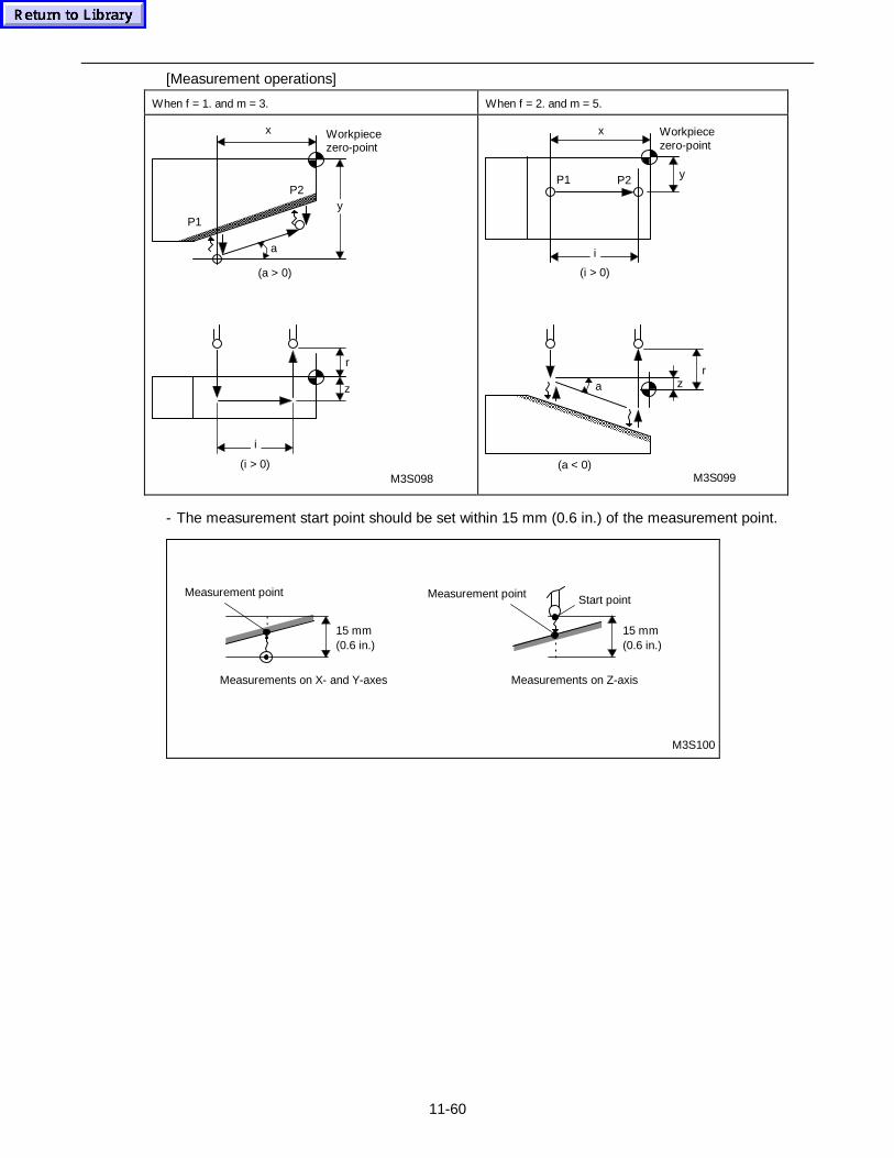
11-60
[Measurement operations]
When f = 1. and m = 3. When f = 2. and m = 5.
z
r
i
(i > 0)
x
yP1
P2
a
(a > 0)
M3S098
Workpiecezero-point
x
yP1
i
(i > 0)
a
(a < 0)
rz
M3S099
P2
Workpiecezero-point
- The measurement start point should be set within 15 mm (0.6 in.) of the measurement point.
Measurements on Z-axisMeasurements on X- and Y-axes
15 mm(0.6 in.)
M3S100
15 mm(0.6 in.)
Start pointMeasurement pointMeasurement point
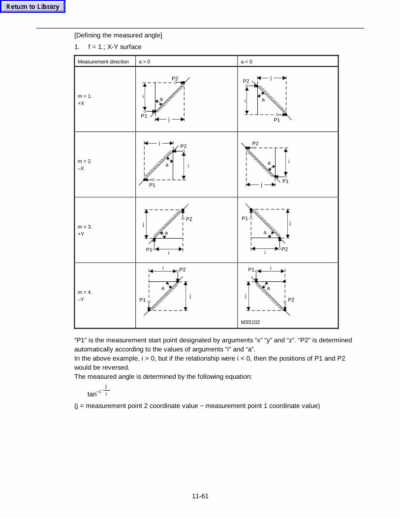
11-61
[Defining the measured angle]
1. f = 1.; X-Y surface
Measurement direction a > 0 a < 0
m = 1.+X
ai
jP1
P2
ai
jP2
P1
m = 2.–X
a i
jP2
P1
a i
jP1
P2
m = 3.+Y a
i
j
P1
P2
a
i
j
P2
P1
m = 4.–Y
a
i
j
P2
P1
a
i
j
P1
P2
M3S102
“P1” is the measurement start point designated by arguments “x” “y” and “z”. “P2” is determinedautomatically according to the values of arguments “i” and “a”.In the above example, i > 0, but if the relationship were i < 0, then the positions of P1 and P2would be reversed.The measured angle is determined by the following equation:
tan–1 j
i
(j = measurement point 2 coordinate value − measurement point 1 coordinate value)
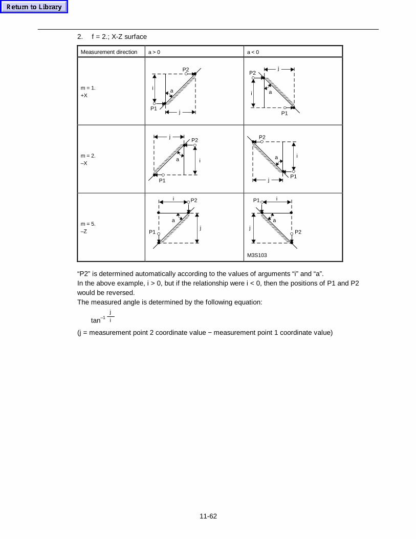
11-62
2. f = 2.; X-Z surface
Measurement direction a > 0 a < 0
m = 1.+X
ai
jP1
P2
ai
jP2
P1
m = 2.–X
a i
jP2
P1
a i
jP1
P2
m = 5.–Z
a
i
j
P2
P1
a
i
j
P1
P2
M3S103
“P2” is determined automatically according to the values of arguments “i” and “a”.In the above example, i > 0, but if the relationship were i < 0, then the positions of P1 and P2would be reversed.The measured angle is determined by the following equation:
tan–1 j
i
(j = measurement point 2 coordinate value − measurement point 1 coordinate value)
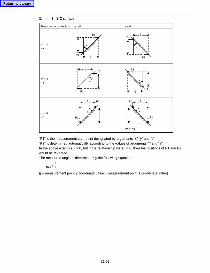
11-63
3. f = 3.; Y-Z surface
Measurement direction a > 0 a < 0
m = 3.+Y
ai
jP1
P2
ai
jP2
P1
m = 4.–Y
a i
jP2
P1
a i
jP1
P2
m = 5.–Z
a
i
j
P2
P1
a
i
j
P1
P2
M3S103
“P1” is the measurement start point designated by arguments “x” “y” and “z”.“P2” is determined automatically according to the values of arguments “i” and “a”.In the above example, i > 0, but if the relationship were i < 0, then the positions of P1 and P2would be reversed.The measured angle is determined by the following equation:
tan–1 j
i
(j = measurement point 2 coordinate value − measurement point 1 coordinate value)
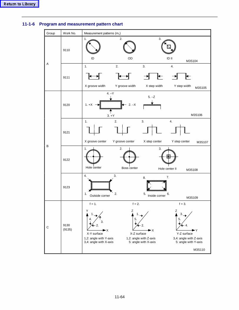
11-64
11-1-6 Program and measurement pattern chart
Group Work No. Measurement patterns (m1)
9110
M3S104ID
1.
ID II
3.
OD
2.
A
9111
X groove width Y step widthX step widthY groove width
1. 2. 3. 4.
M3S105
9120 1. +X 2. –X
3. +Y
4. –Y5. –Z
M3S106
9121
Y step centerX step centerY groove centerX groove center
1. 3.2. 4.
M3S107
9122
Hole center Boss center Hole center II M3S108
1. 3.2.B
9123
Inside corner1.
4.
2.
3.
5.
8.
6.
7.
M3S109Outside corner
C9130(9135)
X-Y surface X-Z surface Y-Z surface
1,2: angle with Y-axis3,4: angle with X-axis
3,4: angle with Z-axis 5: angle with Y-axis
1,2: angle with Z-axis 5: angle with X-axis
f = 1. f = 2. f = 3.
2.3.
4.
1.Y
X
2.
5.
1.Z
X
4.
5.
3.Z
Y
M3S110
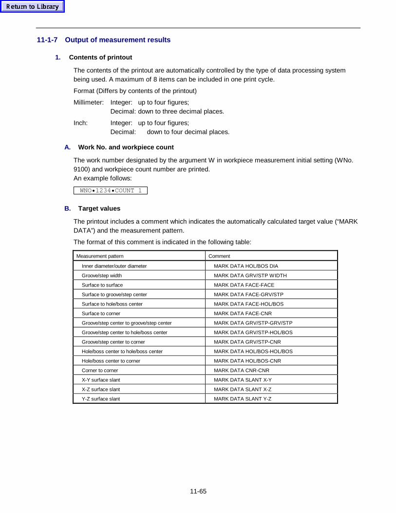
11-65
11-1-7 Output of measurement results
1. Contents of printout
The contents of the printout are automatically controlled by the type of data processing systembeing used. A maximum of 8 items can be included in one print cycle.
Format (Differs by contents of the printout)
Millimeter: Integer: up to four figures;Decimal: down to three decimal places.
Inch: Integer: up to four figures;Decimal: down to four decimal places.
A. Work No. and workpiece c ount
The work number designated by the argument W in workpiece measurement initial setting (WNo.9100) and workpiece count number are printed.An example follows:
WNO• 1234 • COUNT 1
B. Target values
The printout includes a comment which indicates the automatically calculated target value (“MARKDATA”) and the measurement pattern.
The format of this comment is indicated in the following table:
Measurement pattern Comment
Inner diameter/outer diameter MARK DATA HOL/BOS DIA
Groove/step width MARK DATA GRV/STP WIDTH
Surface to surface MARK DATA FACE-FACE
Surface to groove/step center MARK DATA FACE-GRV/STP
Surface to hole/boss center MARK DATA FACE-HOL/BOS
Surface to corner MARK DATA FACE-CNR
Groove/step center to groove/step center MARK DATA GRV/STP-GRV/STP
Groove/step center to hole/boss center MARK DATA GRV/STP-HOL/BOS
Groove/step center to corner MARK DATA GRV/STP-CNR
Hole/boss center to hole/boss center MARK DATA HOL/BOS-HOL/BOS
Hole/boss center to corner MARK DATA HOL/BOS-CNR
Corner to corner MARK DATA CNR-CNR
X-Y surface slant MARK DATA SLANT X-Y
X-Z surface slant MARK DATA SLANT X-Z
Y-Z surface slant MARK DATA SLANT Y-Z
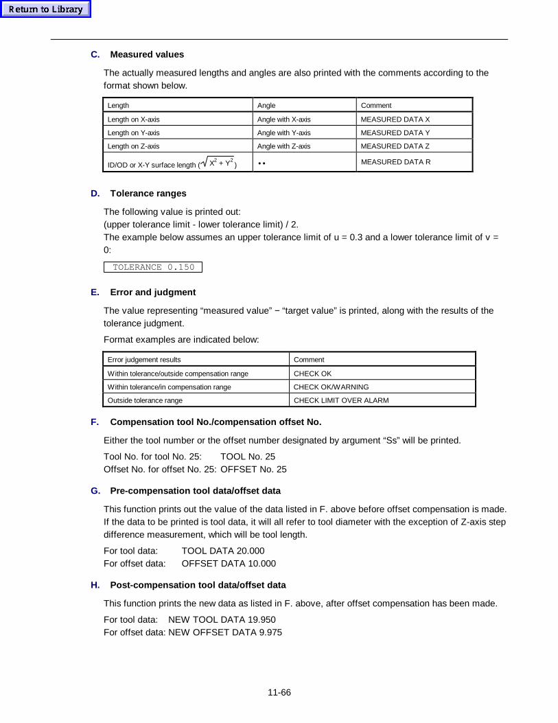
11-66
C. Measured values
The actually measured lengths and angles are also printed with the comments according to theformat shown below.
Length Angle Comment
Length on X-axis Angle with X-axis MEASURED DATA X
Length on Y-axis Angle with Y-axis MEASURED DATA Y
Length on Z-axis Angle with Z-axis MEASURED DATA Z
ID/OD or X-Y surface length ( X2 + Y2) •• MEASURED DATA R
D. Tolerance ranges
The following value is printed out:(upper tolerance limit - lower tolerance limit) / 2.The example below assumes an upper tolerance limit of u = 0.3 and a lower tolerance limit of v =0:
TOLERANCE 0.150
E. Error and judgment
The value representing “measured value” − “target value” is printed, along with the results of thetolerance judgment.
Format examples are indicated below:
Error judgement results Comment
Within tolerance/outside compensation range CHECK OK
Within tolerance/in compensation range CHECK OK/WARNING
Outside tolerance range CHECK LIMIT OVER ALARM
F. Compensation tool No./compensation offset No.
Either the tool number or the offset number designated by argument “Ss” will be printed.
Tool No. for tool No. 25: TOOL No. 25Offset No. for offset No. 25: OFFSET No. 25
G. Pre-compensation tool data/offset data
This function prints out the value of the data listed in F. above before offset compensation is made.If the data to be printed is tool data, it will all refer to tool diameter with the exception of Z-axis stepdifference measurement, which will be tool length.
For tool data: TOOL DATA 20.000For offset data: OFFSET DATA 10.000
H. Post-compensation tool data/offset data
This function prints the new data as listed in F. above, after offset compensation has been made.
For tool data: NEW TOOL DATA 19.950For offset data: NEW OFFSET DATA 9.975
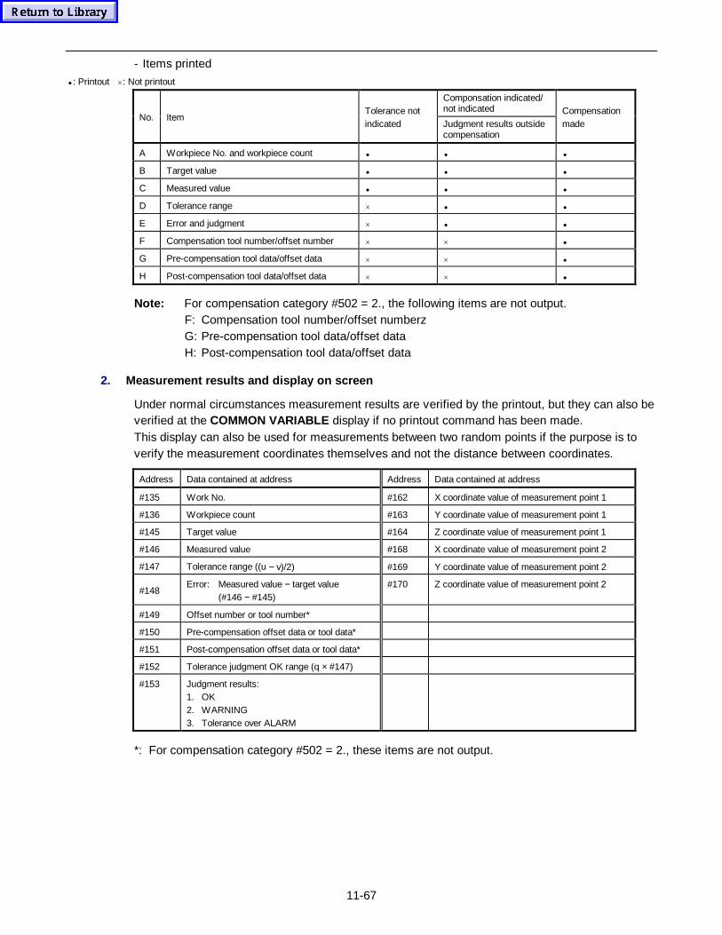
11-67
- Items printed
• : Printout ×: Not printout
Componsation indicated/not indicated
No. ItemTolerance notindicated Judgment results outside
compensation
Compensationmade
A Workpiece No. and workpiece count • • •
B Target value • • •
C Measured value • • •
D Tolerance range × • •
E Error and judgment × • •
F Compensation tool number/offset number × × •
G Pre-compensation tool data/offset data × × •
H Post-compensation tool data/offset data × × •
Note: For compensation category #502 = 2., the following items are not output.F: Compensation tool number/offset numberzG: Pre-compensation tool data/offset dataH: Post-compensation tool data/offset data
2. Measurement results and display on screen
Under normal circumstances measurement results are verified by the printout, but they can also beverified at the COMMON VARIABLE display if no printout command has been made.This display can also be used for measurements between two random points if the purpose is toverify the measurement coordinates themselves and not the distance between coordinates.
Address Data contained at address Address Data contained at address
#135 Work No. #162 X coordinate value of measurement point 1
#136 Workpiece count #163 Y coordinate value of measurement point 1
#145 Target value #164 Z coordinate value of measurement point 1
#146 Measured value #168 X coordinate value of measurement point 2
#147 Tolerance range ((u − v)/2) #169 Y coordinate value of measurement point 2
#148Error: Measured value − target value
(#146 − #145)#170 Z coordinate value of measurement point 2
#149 Offset number or tool number*
#150 Pre-compensation offset data or tool data*
#151 Post-compensation offset data or tool data*
#152 Tolerance judgment OK range (q × #147)
#153 Judgment results:1. OK2. WARNING3. Tolerance over ALARM
*: For compensation category #502 = 2., these items are not output.
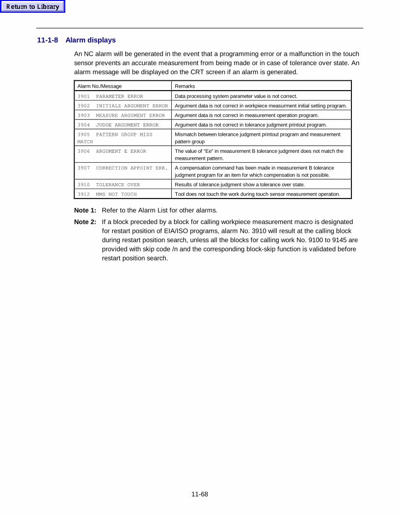
11-68
11-1-8 Alarm displays
An NC alarm will be generated in the event that a programming error or a malfunction in the touchsensor prevents an accurate measurement from being made or in case of tolerance over state. Analarm message will be displayed on the CRT screen if an alarm is generated.
Alarm No./Message Remarks
3901 PARAMETER ERROR Data processing system parameter value is not correct.
3902 INITIALZ ARGUMENT ERROR Argument data is not correct in workpiece measurment initial setting program.
3903 MEASURE ARGUMENT ERROR Argument data is not correct in measurement operation program.
3904 JUDGE ARGUMENT ERROR Argument data is not correct in tolerance judgment printout program.
3905 PATTERN GROUP MISS
MATCH
Mismatch between tolerance judgment printout program and measurementpattern group
3906 ARGUMENT E ERROR The value of “Ee” in measurement B tolerance judgment does not match themeasurement pattern.
3907 CORRECTION APPOINT ERR. A compensation command has been made in measurement B tolerancejudgment program for an item for which compensation is not possible.
3910 TOLERANCE OVER Results of tolerance judgment show a tolerance over state.
3912 MMS NOT TOUCH Tool does not touch the work during touch sensor measurement operation.
Note 1: Refer to the Alarm List for other alarms.
Note 2: If a block preceded by a block for calling workpiece measurement macro is designatedfor restart position of EIA/ISO programs, alarm No. 3910 will result at the calling blockduring restart position search, unless all the blocks for calling work No. 9100 to 9145 areprovided with skip code /n and the corresponding block-skip function is validated beforerestart position search.
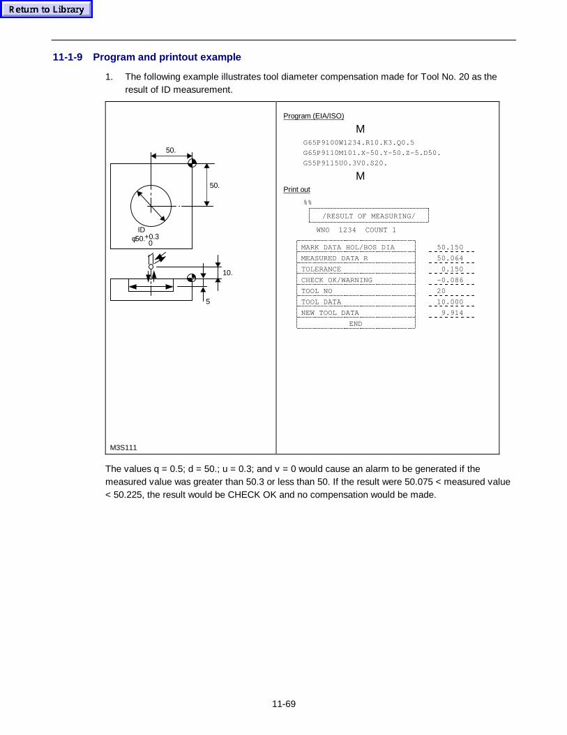
11-69
11-1-9 Program and printout example
1. The following example illustrates tool diameter compensation made for Tool No. 20 as theresult of ID measurement.
50.
50.
10.
5
+0.3 0
IDφ50.
M3S111
The values q = 0.5; d = 50.; u = 0.3; and v = 0 would cause an alarm to be generated if themeasured value was greater than 50.3 or less than 50. If the result were 50.075 < measured value< 50.225, the result would be CHECK OK and no compensation would be made.
Program (EIA/ISO)
ΜG65P9100W1234.R10.K3.Q0.5
G65P9110M101.X-50.Y-50.Z-5.D50.
G55P9115U0.3V0.S20.
ΜPrint out
%%
/RESULT OF MEASURING/
WNO 1234 COUNT 1
MARK DATA HOL/BOS DIA 50.150
MEASURED DATA R 50.064
TOLERANCE 0.150
CHECK OK/WARNING -0.086
TOOL NO 20
TOOL DATA 10.000
NEW TOOL DATA 9.914
END
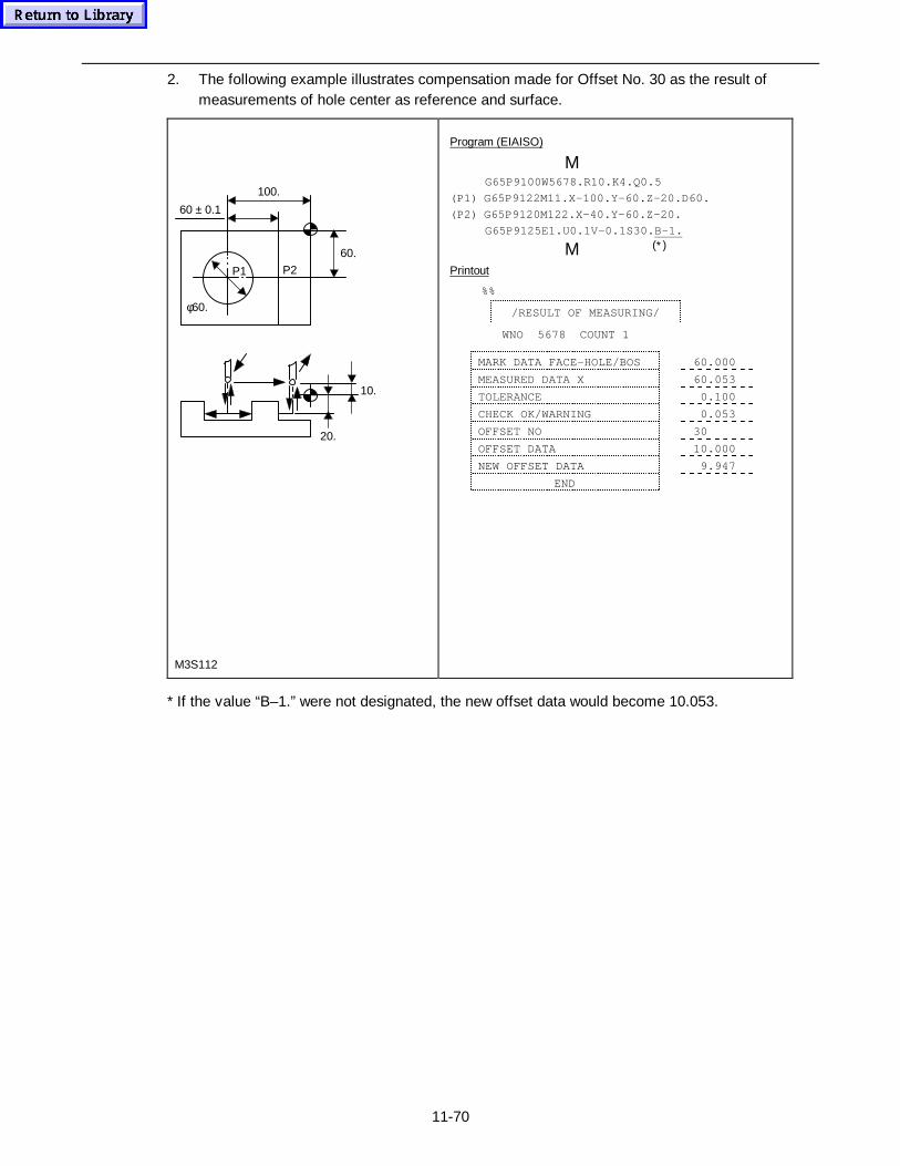
11-70
2. The following example illustrates compensation made for Offset No. 30 as the result ofmeasurements of hole center as reference and surface.
60.
100.
60 ± 0.1
P1
φ60.
P2
10.
20.
M3S112
* If the value “B–1.” were not designated, the new offset data would become 10.053.
Program (EIAISO)
ΜG65P9100W5678.R10.K4.Q0.5
(P1) G65P9122M11.X-100.Y-60.Z-20.D60.
(P2) G65P9120M122.X-40.Y-60.Z-20.
G65P9125E1.U0.1V-0.1S30.B-1.
ΜPrintout
%%
/RESULT OF MEASURING/
WNO 5678 COUNT 1
MARK DATA FACE-HOLE/BOS 60.000
MEASURED DATA X 60.053
TOLERANCE 0.100
CHECK OK/WARNING 0.053
OFFSET NO 30
OFFSET DATA 10.000
NEW OFFSET DATA 9.947
END
(∗)
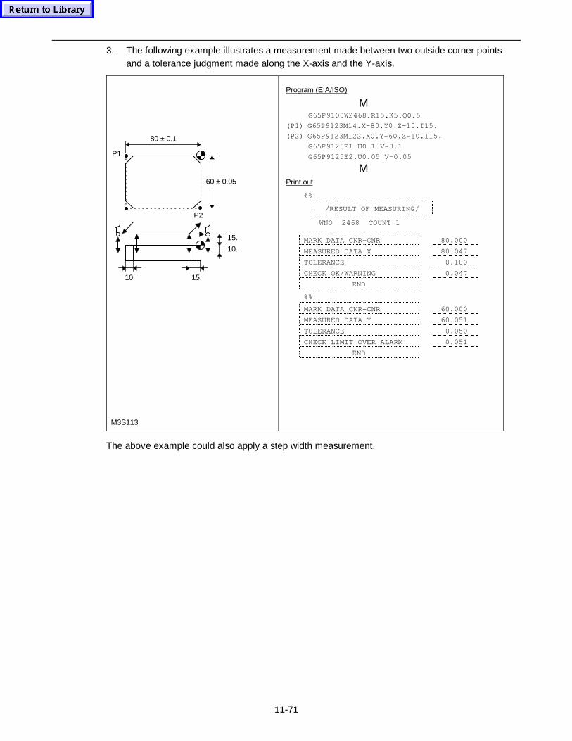
11-71
3. The following example illustrates a measurement made between two outside corner pointsand a tolerance judgment made along the X-axis and the Y-axis.
80 ± 0.1
P1
10.
60 ± 0.05
15.
15.
10.
P2
M3S113
The above example could also apply a step width measurement.
Program (EIA/ISO)
ΜG65P9100W2468.R15.K5.Q0.5
(P1) G65P9123M14.X-80.Y0.Z-10.I15.
(P2) G65P9123M122.X0.Y-60.Z-10.I15.
G65P9125E1.U0.1 V-0.1
G65P9125E2.U0.05 V–0.05
ΜPrint out
%%
/RESULT OF MEASURING/
WNO 2468 COUNT 1
MARK DATA CNR-CNR 80.000
MEASURED DATA X 80.047
TOLERANCE 0.100
CHECK OK/WARNING 0.047
END
%%
MARK DATA CNR-CNR 60.000
MEASURED DATA Y 60.051
TOLERANCE 0.050
CHECK LIMIT OVER ALARM 0.051
END
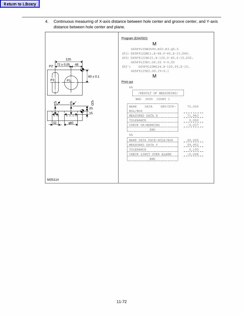
11-72
4. Continuous measuring of X-axis distance between hole center and groove center, and Y-axisdistance between hole center and plane.
32. φ60.
P1P260 ± 0.1
15.
72 ± 0.05
120.
P2’ 48.
20.
M3S114
Program (EIA/ISO)
ΜG65P9100W3690.R20.K3.Q0.5
(P1) G65P9122M11.X-48.Y-60.Z-15.D60.
(P2) G65P9121M121.X-120.Y-60.Z-15.D32.
G65P9125E1.U0.05 V–0.05
(P2’) G65P9120M124.X–120.Y0.Z-15.
G65P9125E2.U0.1V–0.1
ΜPrint out
%%
/RESULT OF MEASURING/
WNO 3690 COUNT 1
MARK DATA GRV/STP-
HOL/BOS
72.000
MEASURED DATA X 71.963
TOLERANCE 0.050
CHECK OK/WARNING –0.037
END
%%
MARK DATA FACE-HOLE/BOS 60.000
MEASURED DATA Y 59.952
TOLERANCE 0.100
CHECK LIMIT OVER ALARM -0.048
END
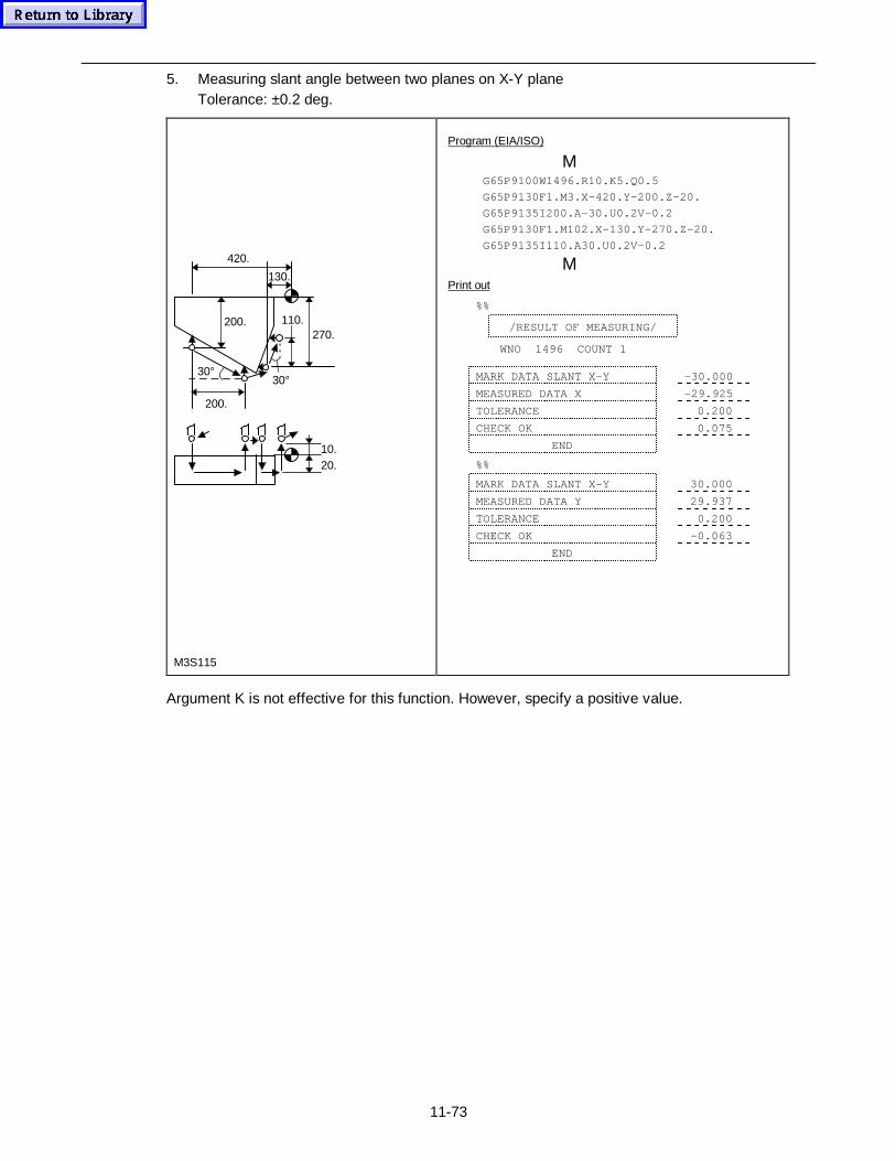
11-73
5. Measuring slant angle between two planes on X-Y planeTolerance: ±0.2 deg.
30°30°
110.270.
200.
200.
420.
130.
20.10.
M3S115
Argument K is not effective for this function. However, specify a positive value.
Program (EIA/ISO)
ΜG65P9100W1496.R10.K5.Q0.5
G65P9130F1.M3.X–420.Y–200.Z–20.
G65P9135I200.A–30.U0.2V–0.2
G65P9130F1.M102.X–130.Y–270.Z–20.
G65P9135I110.A30.U0.2V–0.2
ΜPrint out
%%
/RESULT OF MEASURING/
WNO 1496 COUNT 1
MARK DATA SLANT X-Y –30.000
MEASURED DATA X –29.925
TOLERANCE 0.200
CHECK OK 0.075
END
%%
MARK DATA SLANT X-Y 30.000
MEASURED DATA Y 29.937
TOLERANCE 0.200
CHECK OK –0.063
END
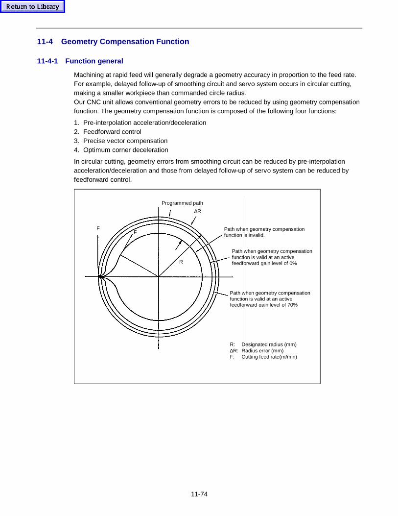
11-74
11-4 Geometry Compensation Function
11-4-1 Function general
Machining at rapid feed will generally degrade a geometry accuracy in proportion to the feed rate.For example, delayed follow-up of smoothing circuit and servo system occurs in circular cutting,making a smaller workpiece than commanded circle radius.Our CNC unit allows conventional geometry errors to be reduced by using geometry compensationfunction. The geometry compensation function is composed of the following four functions:
1. Pre-interpolation acceleration/deceleration2. Feedforward control3. Precise vector compensation4. Optimum corner deceleration
In circular cutting, geometry errors from smoothing circuit can be reduced by pre-interpolationacceleration/deceleration and those from delayed follow-up of servo system can be reduced byfeedforward control.
FF
R
∆R
Programmed path
Path when geometry compensationfunction is invalid.
R: Designated radius (mm)∆R: Radius error (mm)F: Cutting feed rate(m/min)
Path when geometry compensationfunction is valid at an activefeedforward gain level of 0%
Path when geometry compensationfunction is valid at an activefeedforward gain level of 70%
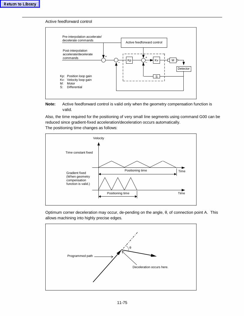
11-75
Active feedforward control
Kp Kv M
Detector
S
+ +
––
Active feedforward control
Pre-interpolation accelerate/decelerate commands
Kp: Position loop gainKv: Velocity loop gainM: MotorS: Differential
Post-interpolationaccelerate/deceleratecommands
Note: Active feedforward control is valid only when the geometry compensation function isvalid.
Also, the time required for the positioning of very small line segments using command G00 can bereduced since gradient-fixed acceleration/deceleration occurs automatically.The positioning time changes as follows:
Time
Time
Velocity
Positioning time
Positioning time
Time constant fixed
Gradient fixed(When geometrycompensationfunction is valid.)
Optimum corner deceleration may occur, de-pending on the angle, θ, of connection point A. Thisallows machining into highly precise edges.
Deceleration occurs here.
Programmed path
θ
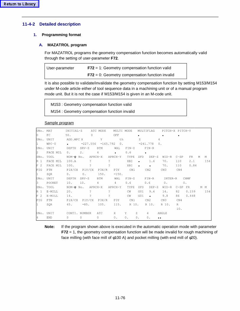
11-76
11-4-2 Detailed description
1. Programm ing fo rmat
A. MAZATROL program
For MAZATROL programs the geometry compensation function becomes automatically validthrough the setting of user-parameter F72.
User-parameter F72 = 1: Geometry compensation function valid
F72 = 0: Geometry compensation function invalid
It is also possible to validate/invalidate the geometry compensation function by setting M153/M154under M-code article either of tool sequence data in a machining unit or of a manual programmode unit. But it is not the case if M153/M154 is given in an M-code unit.
M153 : Geometry compensation function valid
M154 : Geometry compensation function invalid
Sample program
UNo.
0
MAT
FC
INITIAL-Z
50.
ATC MODE
0
MULTI MODE
OFF
MULTIFLAG
•
PITCH-X
•
PITCH-Y
•UNo.
1
UNIT
WPC-0
ADD.WPC
•
X
−227.556
Y
−165.792
th
0.
Z
−241.778
4
0.
UNo.
2
UNIT
FACE MIL
DEPTH
0.
SRV-Z
2.
BTM
4
WAL
•
FIN-Z
0.6
FIN-R
•SNo.
R 1
F 2
TOOL
FACE MIL
FACE MIL
NOM-φ100.A
100.
No. APRCH-X
?
?
APRCH-Y
?
?
TYPE
XBI
XBI
ZFD
•
•
DEP-Z
1.4
•
WID-R
70.
70.
C-SP
110
110
FR
2.1
0.84
M M
154
FIG
1
PTN
SQR
P1X/CX
0.
P1Y/CX
0.
P3X/R
150.
P3Y
−150.
CN1 CN2 CN3 CN4
UNo.
3
UNIT
DEPTH
10.
SRV-Z
10.
BTM
4
WAL
4
FIN-Z
0.6
FIN-R
0.6
INTER-R
0.
CHMF
0.
SNo.
R 1
F 2
TOOL
E-MILL
E-MILL
NOM-φ20.
14.
No. APRCH-X
?
?
APRCH-Y
?
?
TYPE
CW
CW
ZFD
G01
G01
DEP-Z
9.4
•
WID-R
14.
9.8
C-SP
82
86
FR
0.159
0.448
M M
154
FIG
1
PTN
SQR
P1X/CX
45.
P1Y/CX
−85.
P3X/R
105.
P3Y
115.
CN1
R 10.
CN2
R 10.
CN3
R 10.
CN4
R
10.
UNo.
4
UNIT
END
CONTI.
0
NUMBER
0
ATC
0
X
0.
Y
0.
Z
0.
4
0.
ANGLE
••
Note: If the program shown above is executed in the automatic operation mode with parameterF72 = 1, the geometry compensation function will be made invalid for rough machining offace milling (with face mill of φ100 A) and pocket milling (with end mill of φ20).
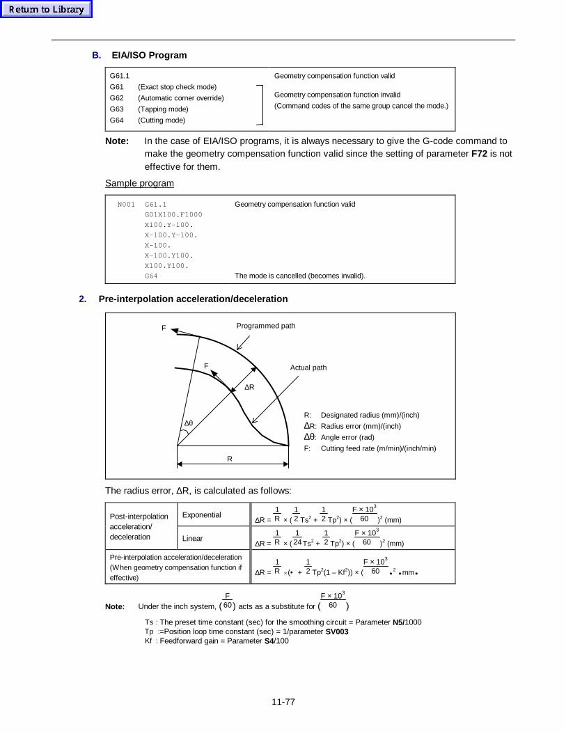
11-77
B. EIA/ISO Program
G61.1
G61 (Exact stop check mode)
G62 (Automatic corner override)
G63 (Tapping mode)
G64 (Cutting mode)
Geometry compensation function valid
Geometry compensation function invalid
(Command codes of the same group cancel the mode.)
Note: In the case of EIA/ISO programs, it is always necessary to give the G-code command tomake the geometry compensation function valid since the setting of parameter F72 is noteffective for them.
Sample program
N001 G61.1
G01X100.F1000
X100.Y-100.
X-100.Y-100.
X-100.
X-100.Y100.
X100.Y100.
G64
Geometry compensation function valid
The mode is cancelled (becomes invalid).
2. Pre-interpolation accelerat ion/d eceleration
F
F
∆R
∆θ
R
R: Designated radius (mm)/(inch)
∆R: Radius error (mm)/(inch)
∆θ: Angle error (rad)
F: Cutting feed rate (m/min)/(inch/min)
Programmed path
Actual path
The radius error, ∆R, is calculated as follows:
Exponential∆R =
1R × (
12 Ts2 +
12 Tp2) × (
F × 103
60 )2 (mm)Post-interpolationacceleration/deceleration Linear
∆R = 1R × (
124Ts2 +
12 Tp2) × (
F × 103
60 )2 (mm)
Pre-interpolation acceleration/deceleration(When geometry compensation function ifeffective)
∆R = 1R ×(• +
12 Tp2(1 – Kf2)) × (
F × 103
60 • 2 • mm•
Note: Under the inch system, (F60) acts as a substitute for (
F × 103
60 )
Ts : The preset time constant (sec) for the smoothing circuit = Parameter N5/1000Tp :=Position loop time constant (sec) = 1/parameter SV003Kf : Feedforward gain = Parameter S4/100
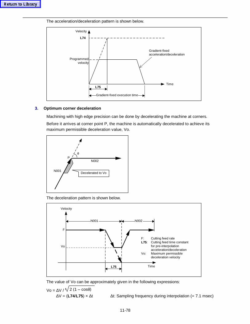
11-78
The acceleration/deceleration pattern is shown below.
Time
Velocity
L75
L74
Gradient-fixed execution time
Programmedvelocity
Gradient-fixedacceleration/deceleration
3. Optimum corner deceleration
Machining with high edge precision can be done by decelerating the machine at corners.
Before it arrives at corner point P, the machine is automatically decelerated to achieve itsmaximum permissible deceleration value, Vo.
N002
Decelerated to VoN001
Pθ
The deceleration pattern is shown below.
Velocity
Vo
F
L75
N001 N002
Time
F: Cutting feed rateL75: Cutting feed time constant
for pre-interpolationacceleration/deceleration
Vo: Maximum permissibledeceleration velocity
The value of Vo can be approximately given in the following expressions:
Vo = ∆V / 2 (1 – cosθ)
∆V = (L74/L75) × ∆t ∆t: Sampling frequency during interpolation (= 7.1 msec)
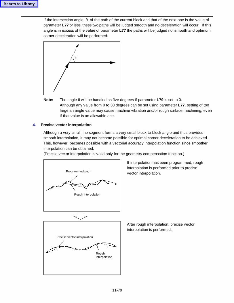
11-79
If the intersection angle, θ, of the path of the current block and that of the next one is the value ofparameter L77 or less, these two paths will be judged smooth and no deceleration will occur. If thisangle is in excess of the value of parameter L77 the paths will be judged nonsmooth and optimumcorner deceleration will be performed.
θ
Note: The angle θ will be handled as five degrees if parameter L79 is set to 0.Although any value from 0 to 30 degrees can be set using parameter L77, setting of toolarge an angle value may cause machine vibration and/or rough surface machining, evenif that value is an allowable one.
4. Precise vector inter polation
Although a very small line segment forms a very small block-to-block angle and thus providessmooth interpolation, it may not become possible for optimal corner deceleration to be achieved.This, however, becomes possible with a vectorial accuracy interpolation function since smootherinterpolation can be obtained.(Precise vector interpolation is valid only for the geometry compensation function.)
Rough interpolation
Programmed path
If interpolation has been programmed, roughinterpolation is performed prior to precisevector interpolation.
Precise vector interpolation
Roughinterpolation
After rough interpolation, precise vectorinterpolation is performed.
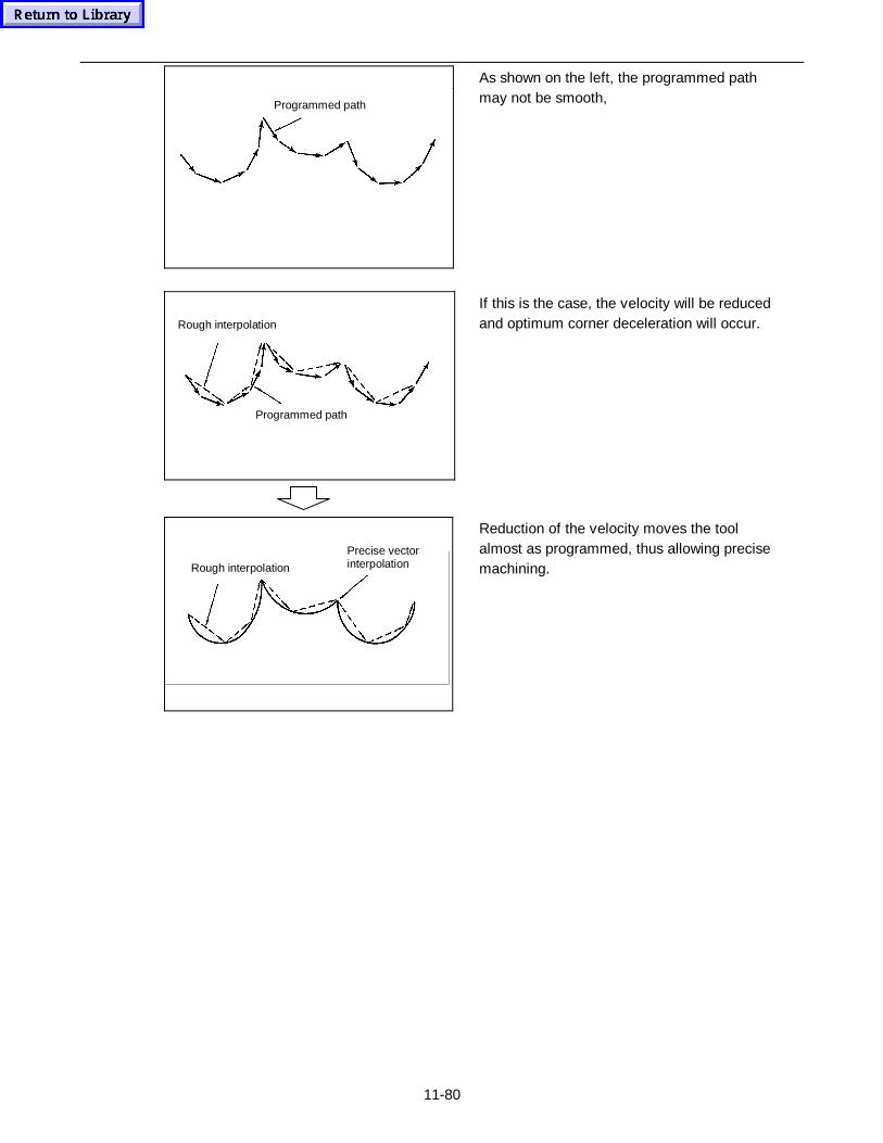
11-80
Programmed path
As shown on the left, the programmed pathmay not be smooth,
Programmed path
Rough interpolation
If this is the case, the velocity will be reducedand optimum corner deceleration will occur.
Precise vectorinterpolationRough interpolation
Reduction of the velocity moves the toolalmost as programmed, thus allowing precisemachining.
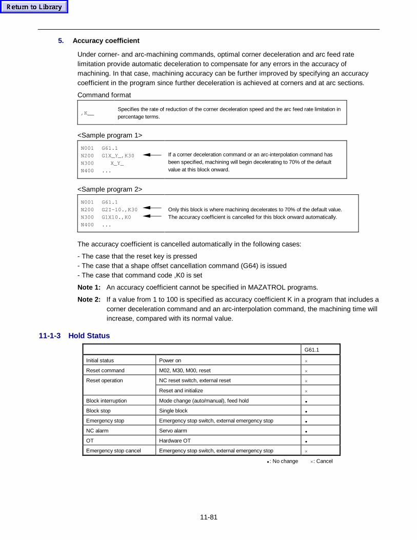
11-81
5. Accuracy coefficient
Under corner- and arc-machining commands, optimal corner deceleration and arc feed ratelimitation provide automatic deceleration to compensate for any errors in the accuracy ofmachining. In that case, machining accuracy can be further improved by specifying an accuracycoefficient in the program since further deceleration is achieved at corners and at arc sections.
Command format
,K__Specifies the rate of reduction of the corner deceleration speed and the arc feed rate limitation inpercentage terms.
<Sample program 1>
N001 G61.1
N200 G1X_Y_,K30
N300 X_Y_
N400 ...
If a corner deceleration command or an arc-interpolation command hasbeen specified, machining will begin decelerating to 70% of the defaultvalue at this block onward.
<Sample program 2>
N001 G61.1
N200 G2I-10.,K30
N300 G1X10.,K0
N400 ...
Only this block is where machining decelerates to 70% of the default value.The accuracy coefficient is cancelled for this block onward automatically.
The accuracy coefficient is cancelled automatically in the following cases:
- The case that the reset key is pressed- The case that a shape offset cancellation command (G64) is issued- The case that command code ,K0 is set
Note 1: An accuracy coefficient cannot be specified in MAZATROL programs.
Note 2: If a value from 1 to 100 is specified as accuracy coefficient K in a program that includes acorner deceleration command and an arc-interpolation command, the machining time willincrease, compared with its normal value.
11-1-3 Hold Status
G61.1
Initial status Power on ×
Reset command M02, M30, M00, reset ×
NC reset switch, external reset ×Reset operation
Reset and initialize ×
Block interruption Mode change (auto/manual), feed hold •
Block stop Single block •
Emergency stop Emergency stop switch, external emergency stop •
NC alarm Servo alarm •
OT Hardware OT •
Emergency stop cancel Emergency stop switch, external emergency stop ×
• : No change ×: Cancel
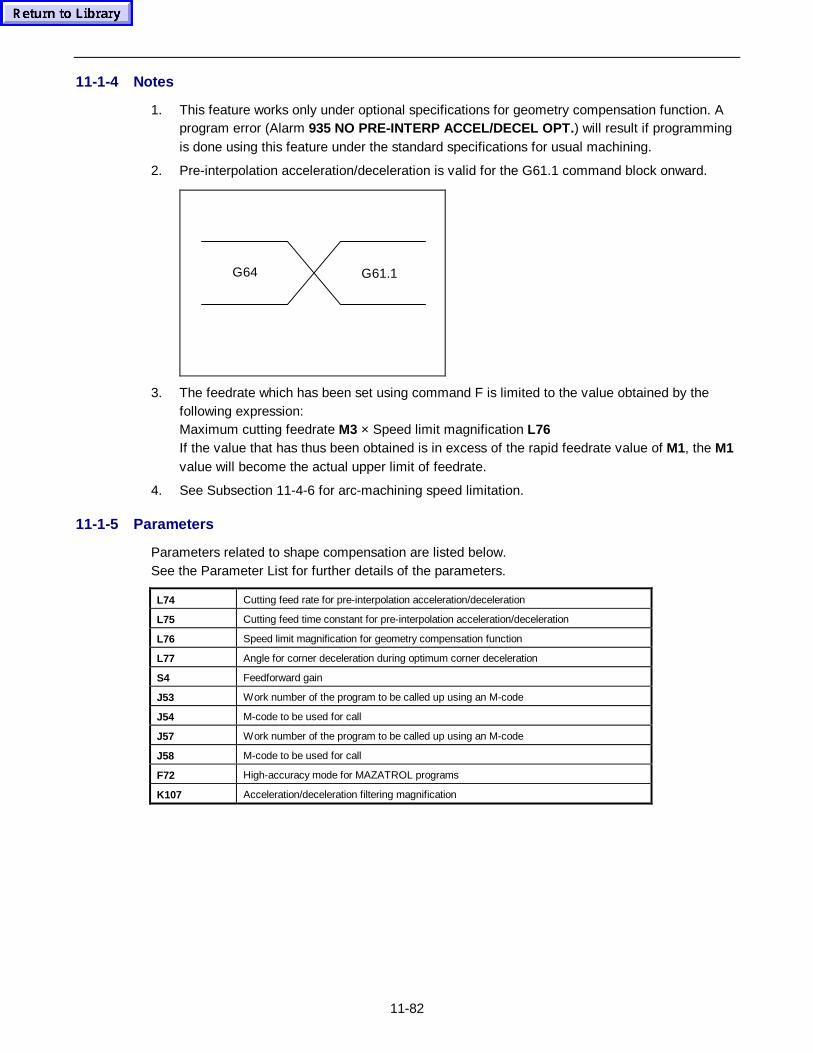
11-82
11-1-4 Notes
1. This feature works only under optional specifications for geometry compensation function. Aprogram error (Alarm 935 NO PRE-INTERP ACCEL/DECEL OPT. ) will result if programmingis done using this feature under the standard specifications for usual machining.
2. Pre-interpolation acceleration/deceleration is valid for the G61.1 command block onward.
G64 G61.1
3. The feedrate which has been set using command F is limited to the value obtained by thefollowing expression:Maximum cutting feedrate M3 × Speed limit magnification L76If the value that has thus been obtained is in excess of the rapid feedrate value of M1, the M1value will become the actual upper limit of feedrate.
4. See Subsection 11-4-6 for arc-machining speed limitation.
11-1-5 Parameters
Parameters related to shape compensation are listed below.See the Parameter List for further details of the parameters.
L74 Cutting feed rate for pre-interpolation acceleration/deceleration
L75 Cutting feed time constant for pre-interpolation acceleration/deceleration
L76 Speed limit magnification for geometry compensation function
L77 Angle for corner deceleration during optimum corner deceleration
S4 Feedforward gain
J53 Work number of the program to be called up using an M-code
J54 M-code to be used for call
J57 Work number of the program to be called up using an M-code
J58 M-code to be used for call
F72 High-accuracy mode for MAZATROL programs
K107 Acceleration/deceleration filtering magnification
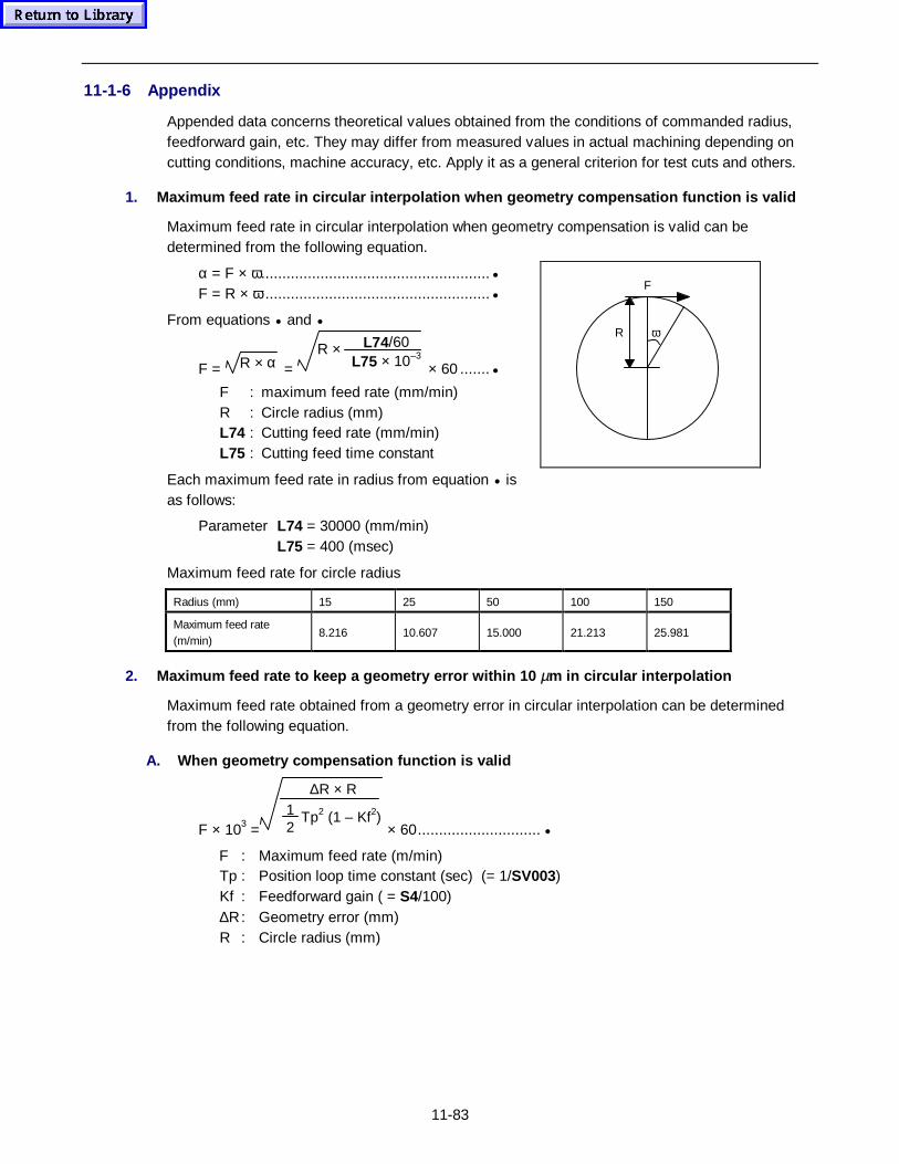
11-83
11-1-6 Appendix
Appended data concerns theoretical values obtained from the conditions of commanded radius,feedforward gain, etc. They may differ from measured values in actual machining depending oncutting conditions, machine accuracy, etc. Apply it as a general criterion for test cuts and others.
1. Maximum feed rate in circular interpolation when geometry compensation function is valid
Maximum feed rate in circular interpolation when geometry compensation is valid can bedetermined from the following equation.
α = F × ω......................................................•F = R × ω .....................................................•
From equations • and •
F = R × α =
L74/60L75 × 10–3R ×
× 60 .......•
F : maximum feed rate (mm/min)R : Circle radius (mm)L74 : Cutting feed rate (mm/min)L75 : Cutting feed time constant
Each maximum feed rate in radius from equation • isas follows:
ωR
F
Parameter L74 = 30000 (mm/min)L75 = 400 (msec)
Maximum feed rate for circle radius
Radius (mm) 15 25 50 100 150
Maximum feed rate(m/min)
8.216 10.607 15.000 21.213 25.981
2. Maximum feed rate to keep a geometry error wit hin 10 µm in circular interpolation
Maximum feed rate obtained from a geometry error in circular interpolation can be determinedfrom the following equation.
A. When geometry compensation function is valid
F × 103 =
∆R × R12
Tp2 (1 – Kf2) × 60............................. •
F : Maximum feed rate (m/min)Tp : Position loop time constant (sec) (= 1/SV003)Kf : Feedforward gain ( = S4/100)∆R: Geometry error (mm)R : Circle radius (mm)
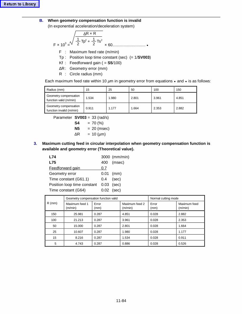
11-84
B. When geometry compensation function is invalid(In exponential acceleration/deceleration system)
F × 103 =
∆R × R
12
Tp2 + 12
Ts2
× 60............................. •
F : Maximum feed rate (m/min)Tp : Position loop time constant (sec) (= 1/SV003)Kf : Feedforward gain ( = S5/100)∆R: Geometry error (mm)R : Circle radius (mm)
Each maximum feed rate within 10 µm in geometry error from equations • and • is as follows:
Radius (mm) 15 25 50 100 150
Geometry compensationfunction valid (m/min)
1.534 1.980 2.801 3.961 4.851
Geometry compensationfunction invalid (m/min)
0.911 1.177 1.664 2.353 2.882
Parameter SV003 = 33 (rad/s)S4 = 70 (%)N5 = 20 (msec)∆R = 10 (µm)
3. Maximum cutting feed in circular interpolation when geometry compensation function isavailable and geometry error (Theoretical value).
L74 3000 (mm/min)L75 400 (msec)Feedforward gain 0.7Geometry error 0.01 (mm)Time constant (G61.1) 0.4 (sec)Position loop time constant 0.03 (sec)Time constant (G64) 0.02 (sec)
Geometry compensation function valid Normal cutting mode
R (mm) Maximum feed 1(m/min)
Error(mm)
Maximum feed 2(m/min)
Error(mm)
Maximum feed(m/min)
150 25.981 0.287 4.851 0.028 2.882
100 21.213 0.287 3.961 0.028 2.353
50 15.000 0.287 2.801 0.028 1.664
25 10.607 0.287 1.980 0.028 1.177
15 8.216 0.287 1.534 0.028 0.911
5 4.743 0.287 0.886 0.028 0.526
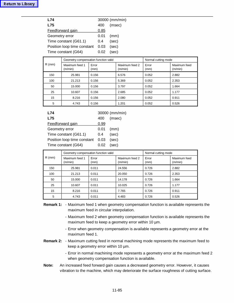
11-85
L74 30000 (mm/min)L75 400 (msec)Feedforward gain 0.85Geometry error 0.01 (mm)Time constant (G61.1) 0.4 (sec)Position loop time constant 0.03 (sec)Time constant (G64) 0.02 (sec)
Geometry compensation function valid Normal cutting mode
R (mm) Maximum feed 1(m/min)
Error(mm)
Maximum feed 2(m/min)
Error(mm)
Maximum feed(m/min)
150 25.981 0.156 6.576 0.052 2.882
100 21.213 0.156 5.369 0.052 2.353
50 15.000 0.156 3.797 0.052 1.664
25 10.607 0.156 2.685 0.052 1.177
15 8.216 0.156 2.080 0.052 0.911
5 4.743 0.156 1.201 0.052 0.526
L74 30000 (mm/min)L75 400 (msec)Feedforward gain 0.99Geometry error 0.01 (mm)Time constant (G61.1) 0.4 (sec)Position loop time constant 0.03 (sec)Time constant (G64) 0.02 (sec)
Geometry compensation function valid Normal cutting mode
R (mm) Maximum feed 1(m/min)
Error(mm)
Maximum feed 2(m/min)
Error(mm)
Maximum feed(m/min)
150 25.981 0.011 24.556 0.726 2.882
100 21.213 0.011 20.050 0.726 2.353
50 15.000 0.011 14.178 0.726 1.664
25 10.607 0.011 10.025 0.726 1.177
15 8.216 0.011 7.765 0.726 0.911
5 4.743 0.011 4.483 0.726 0.526
Remark 1: - Maximum feed 1 when geometry compensation function is available represents themaximum feed in circular interpolation.
- Maximum feed 2 when geometry compensation function is available represents themaximum feed to keep a geometry error within 10 µm.
- Error when geometry compensation is available represents a geometry error at themaximum feed 1.
Remark 2: - Maximum cutting feed in normal machining mode represents the maximum feed tokeep a geometry error within 10 µm.
- Error in normal machining mode represents a geometry error at the maximum feed 2when geometry compensation function is available.
Note: An increased feed forward gain causes a decreased geometry error. However, it causesvibration to the machine, which may deteriorate the surface roughness of cutting surface.
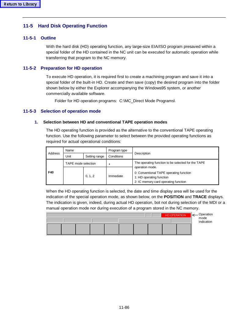
11-86
11-5 Hard Disk Operating Function
11-5-1 Outline
With the hard disk (HD) operating function, any large-size EIA/ISO program presaved within aspecial folder of the HD contained in the NC unit can be executed for automatic operation whiletransferring that program to the NC memory.
11-5-2 Preparation for HD operation
To execute HD operation, it is required first to create a machining program and save it into aspecial folder of the built-in HD. Create and then save (copy) the desired program into the foldershown below by either the Explorer accompanying the Windows95 system, or anothercommercially available software.
Folder for HD operation programs: C:\MC_Direct Mode Programs\
11-5-3 Selection of operation mode
1. Selection between HD and conventional TAPE op erat ion modes
The HD operating function is provided as the alternative to the conventional TAPE operatingfunction. Use the following parameter to select between the provided operating functions asrequired for actual operational conditions:
Name Program typeAddress
Unit Setting range ConditionsDescription
TAPE mode selection •
F400, 1, 2 Immediate
The operating function to be selected for the TAPEoperation mode.
0: Conventional TAPE operating function1: HD operating function2: IC memory card operating function
When the HD operating function is selected, the date and time display area will be used for theindication of the special operation mode, as shown below, on the POSITION and TRACE displays.The indication is given, indeed, during actual HD operation, bot not during selection of the MDI or amanual operation mode nor during execution of a program stored in the NC memory.
Operationmodeindication

11-87
2. HD operat ion modes
The HD operating function can be used in the following two modes:
1. Direct operation modeA program stored on the HD operates as the main program.
2. Subprogram operation modeA program stored on the HD is called up as the subprogram from a main program registered inthe NC memory.
Press the TAPE key to select the direct operation mode, and the MEMORY key to use thesubprogram operation mode of the HD operating function.
TAPE MEMORY
TAPE operation key MEMORY operation key
3. Restrict ions con cerning the •• operat ing function
General restrictions on the HD operation are as follows:
- Only programs of the EIA/ISO format can be used for the HD operation.
- Programs stored on the HD cannot be checked for tool path and machining shape on the TOOLPATH display.
- Programs stored on the HD cannot be edited on the PROGRAM (EIA) display. Use acommercially available editor capable of editing text files.
- Programs stored on the HD cannot be presented on the EIA MONITOR display.
- The RESTART 2 NONMODAL menu function cannot be applied to a program stored on the HD.
- Programs stored on the HD cannot be subjected to the external work number search.
Further particular restrictions for each HD operation mode are as follows:
For direct operation mode
- The HD main program cannot call another HD program as a subprogram. On a subprogram-callcommand from the HD main program can only the NC memory be searched for, and an alarmwill be given if the specified program is not found there.
- An NC subprogram called up from the HD main program cannot call another HD program as thefurther subroutine.
- An alarm will be caused if an “ M99” command (used for return from subprogram) is given inthe HD main program.
For subprogram operation mode
- The HD subprogram cannot call another HD program as a subprogram. On a further subprogram-call command from the HD subprogram can only the NC memory be searched for, and an alarmwill be given if the specified program is not found there.
- Sequence number specification for subprogram call by “ M98H∗∗” is not effective in calling up
11-88
an HD program. The HD subprogram is always executed from the beginning.
- Repeat time specification for subprogram call is not effective in calling up an HD program. TheHD subprogram is always executed only one time for one call command.
- The subprogram call from the NC main program preferably selects a program in the NC memoryto that on the HD in case the specified work number should have been assigned to the bothprograms.
- With MAZATROL programs in the NC memory, use a subprogram unit or “ G65” (non-modaluser macro call) in a manual-program unit for the HD subprogram operation mode.
11-1-4 Program selection for HD operation
This subsection describes the operating procedure for selecting the program in each mode for HDoperating function.
1. Direct operat ion mode
(1) Select the machine operating mode for the direct HD operation mode.
- Press the TAPE operation key .
(2) Select the POSITION display on the screen.
- This is required for selecting the program to be run and checking the operational status ofthe machine.
(3) Specify the desired program stored on the HD.
- Proceed as follows to specify the program:
1) Press the WORK No. menu key.The display of the menu item is reversed and the work-number listing window appears.
2) Select the desired program from among those stored on the HD.To specify the program of work No. 100, for example:
Example 1: Press the keys 1 0 0 in this order.
Example 2: Press a cursor key to call up the cursor, move the cursor onto thedisplayed work number “100” in the window, and then press the INPUT key
.
Carry out the above procedural steps, referred to as “HD work number search”, to start the directHD operation.
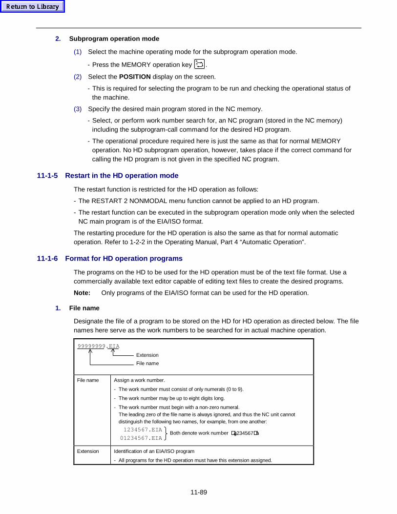
11-89
2. Subprog ram operat ion mode
(1) Select the machine operating mode for the subprogram operation mode.
- Press the MEMORY operation key .
(2) Select the POSITION display on the screen.
- This is required for selecting the program to be run and checking the operational status ofthe machine.
(3) Specify the desired main program stored in the NC memory.
- Select, or perform work number search for, an NC program (stored in the NC memory)including the subprogram-call command for the desired HD program.
- The operational procedure required here is just the same as that for normal MEMORYoperation. No HD subprogram operation, however, takes place if the correct command forcalling the HD program is not given in the specified NC program.
11-1-5 Restart in the HD operation mode
The restart function is restricted for the HD operation as follows:
- The RESTART 2 NONMODAL menu function cannot be applied to an HD program.
- The restart function can be executed in the subprogram operation mode only when the selectedNC main program is of the EIA/ISO format.
The restarting procedure for the HD operation is also the same as that for normal automaticoperation. Refer to 1-2-2 in the Operating Manual, Part 4 “Automatic Operation”.
11-1-6 Format for HD operation programs
The programs on the HD to be used for the HD operation must be of the text file format. Use acommercially available text editor capable of editing text files to create the desired programs.
Note: Only programs of the EIA/ISO format can be used for the HD operation.
1. File name
Designate the file of a program to be stored on the HD for HD operation as directed below. The filenames here serve as the work numbers to be searched for in actual machine operation.
File name
Extension
99999999.EIA
File name Assign a work number.
- The work number must consist of only numerals (0 to 9).
- The work number may be up to eight digits long.
- The work number must begin with a non-zero numeral.The leading zero of the file name is always ignored, and thus the NC unit cannotdistinguish the following two names, for example, from one another:
Both denote work number �J1234567�K.1234567.EIA
01234567.EIA
Extension Identification of an EIA/ISO program
- All programs for the HD operation must have this extension assigned.
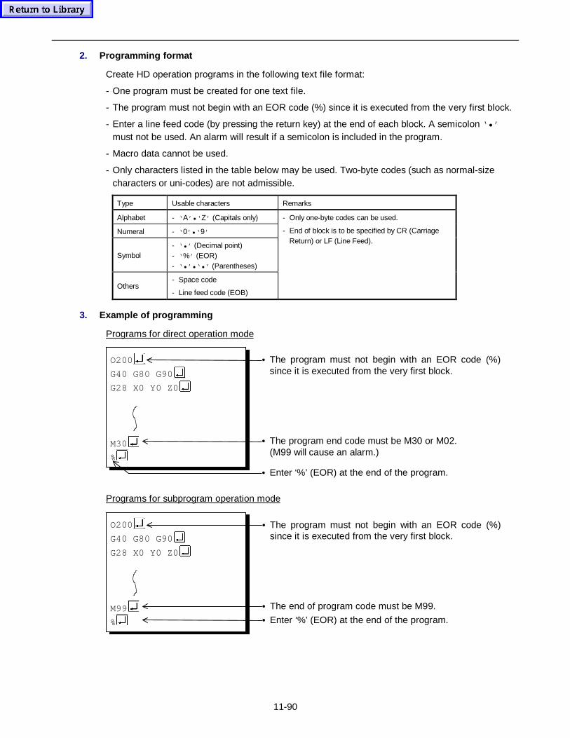
11-90
2. Programm ing fo rmat
Create HD operation programs in the following text file format:
- One program must be created for one text file.
- The program must not begin with an EOR code (%) since it is executed from the very first block.
- Enter a line feed code (by pressing the return key) at the end of each block. A semicolon ‘•’must not be used. An alarm will result if a semicolon is included in the program.
- Macro data cannot be used.
- Only characters listed in the table below may be used. Two-byte codes (such as normal-sizecharacters or uni-codes) are not admissible.
Type Usable characters Remarks
Alphabet - ‘ A’•‘ Z’ (Capitals only)
Numeral - ‘ 0’•‘ 9’
Symbol- ‘•’ (Decimal point)- ‘ %’ (EOR)- ‘•’•‘•’ (Parentheses)
Others- Space code
- Line feed code (EOB)
- Only one-byte codes can be used.
- End of block is to be specified by CR (CarriageReturn) or LF (Line Feed).
3. Example of programming
Programs for direct operation mode
O200
G40 G80 G90
G28 X0 Y0 Z0
M30
%
• The program must not begin with an EOR code (%)since it is executed from the very first block.
• The program end code must be M30 or M02.
(M99 will cause an alarm.)
• Enter ‘%’ (EOR) at the end of the program.
Programs for subprogram operation mode
O200
G40 G80 G90
G28 X0 Y0 Z0
M99
%
• The program must not begin with an EOR code (%)since it is executed from the very first block.
• The end of program code must be M99.
• Enter ‘%’ (EOR) at the end of the program.
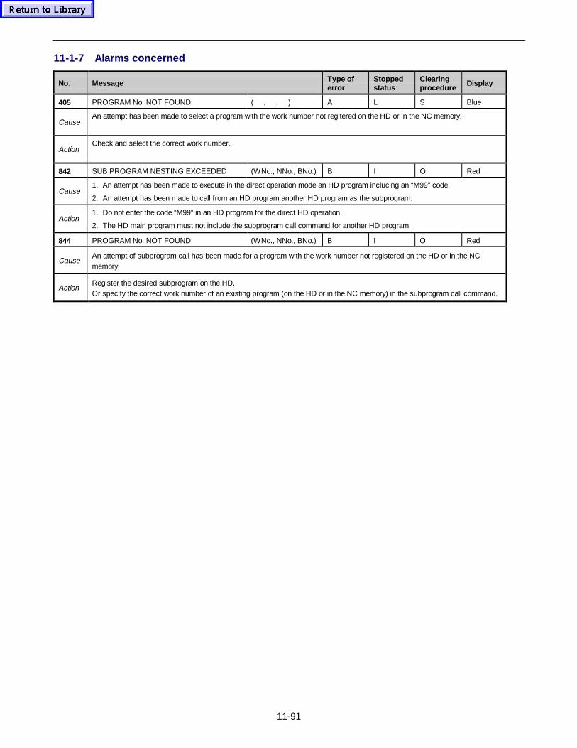
11-91
11-1-7 Alarms concerned
No. Message Type oferror
Stoppedstatus
Clearingprocedure
Display
405 PROGRAM No. NOT FOUND ( , , ) A L S Blue
CauseAn attempt has been made to select a program with the work number not regitered on the HD or in the NC memory.
ActionCheck and select the correct work number.
842 SUB PROGRAM NESTING EXCEEDED (WNo., NNo., BNo.) B I O Red
Cause1. An attempt has been made to execute in the direct operation mode an HD program inclucing an “M99” code.
2. An attempt has been made to call from an HD program another HD program as the subprogram.
Action1. Do not enter the code “M99” in an HD program for the direct HD operation.
2. The HD main program must not include the subprogram call command for another HD program.
844 PROGRAM No. NOT FOUND (WNo., NNo., BNo.) B I O Red
CauseAn attempt of subprogram call has been made for a program with the work number not registered on the HD or in the NCmemory.
ActionRegister the desired subprogram on the HD.Or specify the correct work number of an existing program (on the HD or in the NC memory) in the subprogram call command.
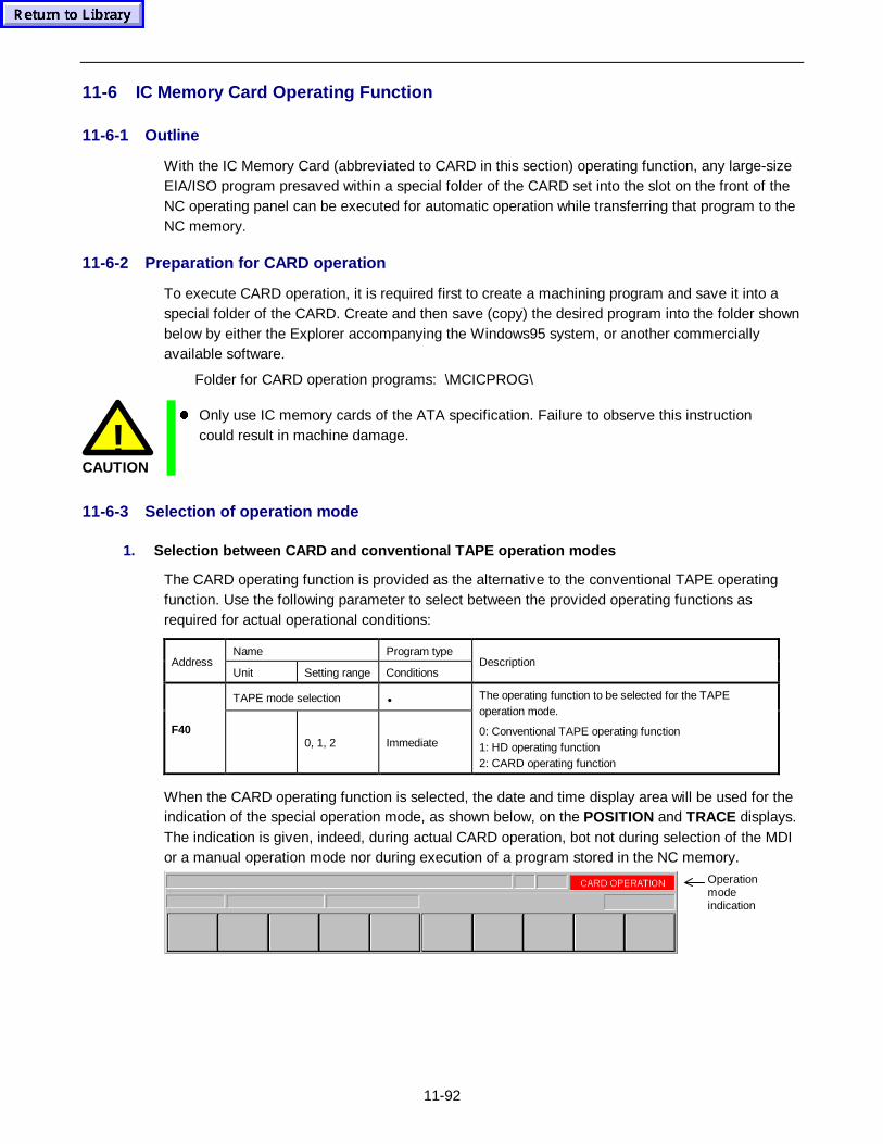
11-92
11-6 IC Memory Card Operating Function
11-6-1 Outline
With the IC Memory Card (abbreviated to CARD in this section) operating function, any large-sizeEIA/ISO program presaved within a special folder of the CARD set into the slot on the front of theNC operating panel can be executed for automatic operation while transferring that program to theNC memory.
11-6-2 Preparation for CARD operation
To execute CARD operation, it is required first to create a machining program and save it into aspecial folder of the CARD. Create and then save (copy) the desired program into the folder shownbelow by either the Explorer accompanying the Windows95 system, or another commerciallyavailable software.
Folder for CARD operation programs: \MCICPROG\
!CAUTION
z Only use IC memory cards of the ATA specification. Failure to observe this instructioncould result in machine damage.
11-6-3 Selection of operation mode
1. Selection between CARD and conventional TAPE op erat ion modes
The CARD operating function is provided as the alternative to the conventional TAPE operatingfunction. Use the following parameter to select between the provided operating functions asrequired for actual operational conditions:
Name Program typeAddress
Unit Setting range ConditionsDescription
TAPE mode selection •
F400, 1, 2 Immediate
The operating function to be selected for the TAPEoperation mode.
0: Conventional TAPE operating function1: HD operating function2: CARD operating function
When the CARD operating function is selected, the date and time display area will be used for theindication of the special operation mode, as shown below, on the POSITION and TRACE displays.The indication is given, indeed, during actual CARD operation, bot not during selection of the MDIor a manual operation mode nor during execution of a program stored in the NC memory.
Operationmodeindication
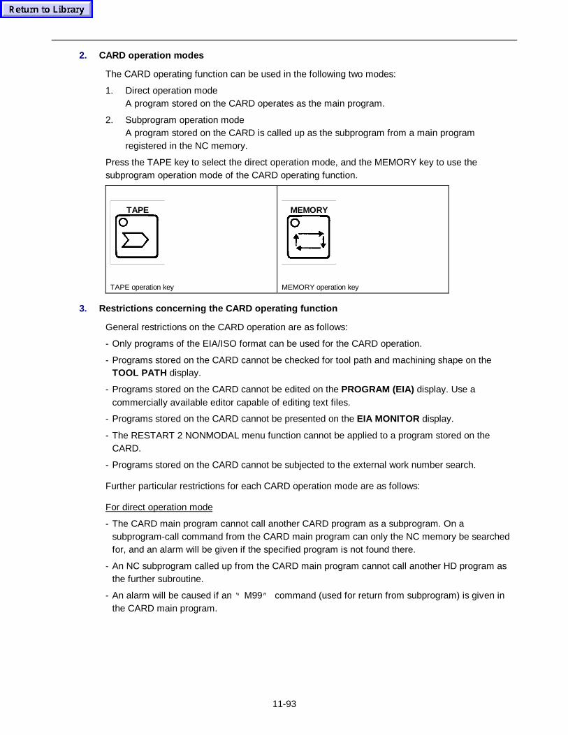
11-93
2. CARD operat ion modes
The CARD operating function can be used in the following two modes:
1. Direct operation modeA program stored on the CARD operates as the main program.
2. Subprogram operation modeA program stored on the CARD is called up as the subprogram from a main programregistered in the NC memory.
Press the TAPE key to select the direct operation mode, and the MEMORY key to use thesubprogram operation mode of the CARD operating function.
TAPE MEMORY
TAPE operation key MEMORY operation key
3. Restrict ions con cerning the CARD op erat ing function
General restrictions on the CARD operation are as follows:
- Only programs of the EIA/ISO format can be used for the CARD operation.
- Programs stored on the CARD cannot be checked for tool path and machining shape on theTOOL PATH display.
- Programs stored on the CARD cannot be edited on the PROGRAM (EIA) display. Use acommercially available editor capable of editing text files.
- Programs stored on the CARD cannot be presented on the EIA MONITOR display.
- The RESTART 2 NONMODAL menu function cannot be applied to a program stored on theCARD.
- Programs stored on the CARD cannot be subjected to the external work number search.
Further particular restrictions for each CARD operation mode are as follows:
For direct operation mode
- The CARD main program cannot call another CARD program as a subprogram. On asubprogram-call command from the CARD main program can only the NC memory be searchedfor, and an alarm will be given if the specified program is not found there.
- An NC subprogram called up from the CARD main program cannot call another HD program asthe further subroutine.
- An alarm will be caused if an “ M99” command (used for return from subprogram) is given inthe CARD main program.
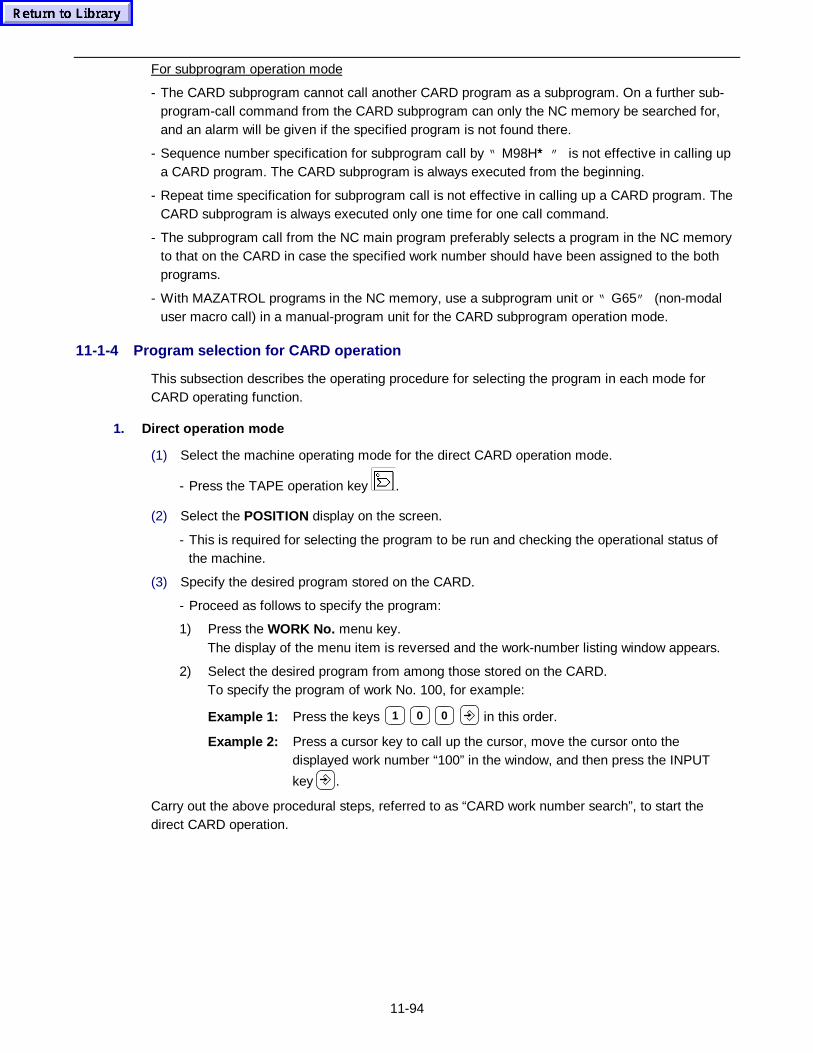
11-94
For subprogram operation mode
- The CARD subprogram cannot call another CARD program as a subprogram. On a further sub-program-call command from the CARD subprogram can only the NC memory be searched for,and an alarm will be given if the specified program is not found there.
- Sequence number specification for subprogram call by “ M98H∗∗” is not effective in calling upa CARD program. The CARD subprogram is always executed from the beginning.
- Repeat time specification for subprogram call is not effective in calling up a CARD program. TheCARD subprogram is always executed only one time for one call command.
- The subprogram call from the NC main program preferably selects a program in the NC memoryto that on the CARD in case the specified work number should have been assigned to the bothprograms.
- With MAZATROL programs in the NC memory, use a subprogram unit or “ G65” (non-modaluser macro call) in a manual-program unit for the CARD subprogram operation mode.
11-1-4 Program selection for CARD operation
This subsection describes the operating procedure for selecting the program in each mode forCARD operating function.
1. Direct operat ion mode
(1) Select the machine operating mode for the direct CARD operation mode.
- Press the TAPE operation key .
(2) Select the POSITION display on the screen.
- This is required for selecting the program to be run and checking the operational status ofthe machine.
(3) Specify the desired program stored on the CARD.
- Proceed as follows to specify the program:
1) Press the WORK No. menu key.The display of the menu item is reversed and the work-number listing window appears.
2) Select the desired program from among those stored on the CARD.To specify the program of work No. 100, for example:
Example 1: Press the keys 1 0 0 in this order.
Example 2: Press a cursor key to call up the cursor, move the cursor onto thedisplayed work number “100” in the window, and then press the INPUT
key .
Carry out the above procedural steps, referred to as “CARD work number search”, to start thedirect CARD operation.
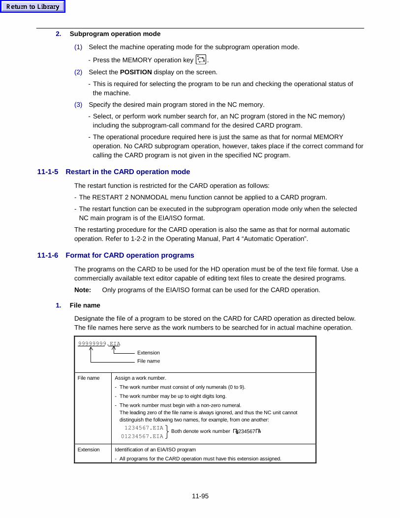
11-95
2. Subprog ram operat ion mode
(1) Select the machine operating mode for the subprogram operation mode.
- Press the MEMORY operation key .
(2) Select the POSITION display on the screen.
- This is required for selecting the program to be run and checking the operational status ofthe machine.
(3) Specify the desired main program stored in the NC memory.
- Select, or perform work number search for, an NC program (stored in the NC memory)including the subprogram-call command for the desired CARD program.
- The operational procedure required here is just the same as that for normal MEMORYoperation. No CARD subprogram operation, however, takes place if the correct command forcalling the CARD program is not given in the specified NC program.
11-1-5 Restart in the CARD operation mode
The restart function is restricted for the CARD operation as follows:
- The RESTART 2 NONMODAL menu function cannot be applied to a CARD program.
- The restart function can be executed in the subprogram operation mode only when the selectedNC main program is of the EIA/ISO format.
The restarting procedure for the CARD operation is also the same as that for normal automaticoperation. Refer to 1-2-2 in the Operating Manual, Part 4 “Automatic Operation”.
11-1-6 Format for CARD operation programs
The programs on the CARD to be used for the HD operation must be of the text file format. Use acommercially available text editor capable of editing text files to create the desired programs.
Note: Only programs of the EIA/ISO format can be used for the CARD operation.
1. File name
Designate the file of a program to be stored on the CARD for CARD operation as directed below.The file names here serve as the work numbers to be searched for in actual machine operation.
File name
Extension
99999999.EIA
File name Assign a work number.
- The work number must consist of only numerals (0 to 9).
- The work number may be up to eight digits long.
- The work number must begin with a non-zero numeral.The leading zero of the file name is always ignored, and thus the NC unit cannotdistinguish the following two names, for example, from one another:
Both denote work number �J1234567�K.1234567.EIA
01234567.EIA
Extension Identification of an EIA/ISO program
- All programs for the CARD operation must have this extension assigned.
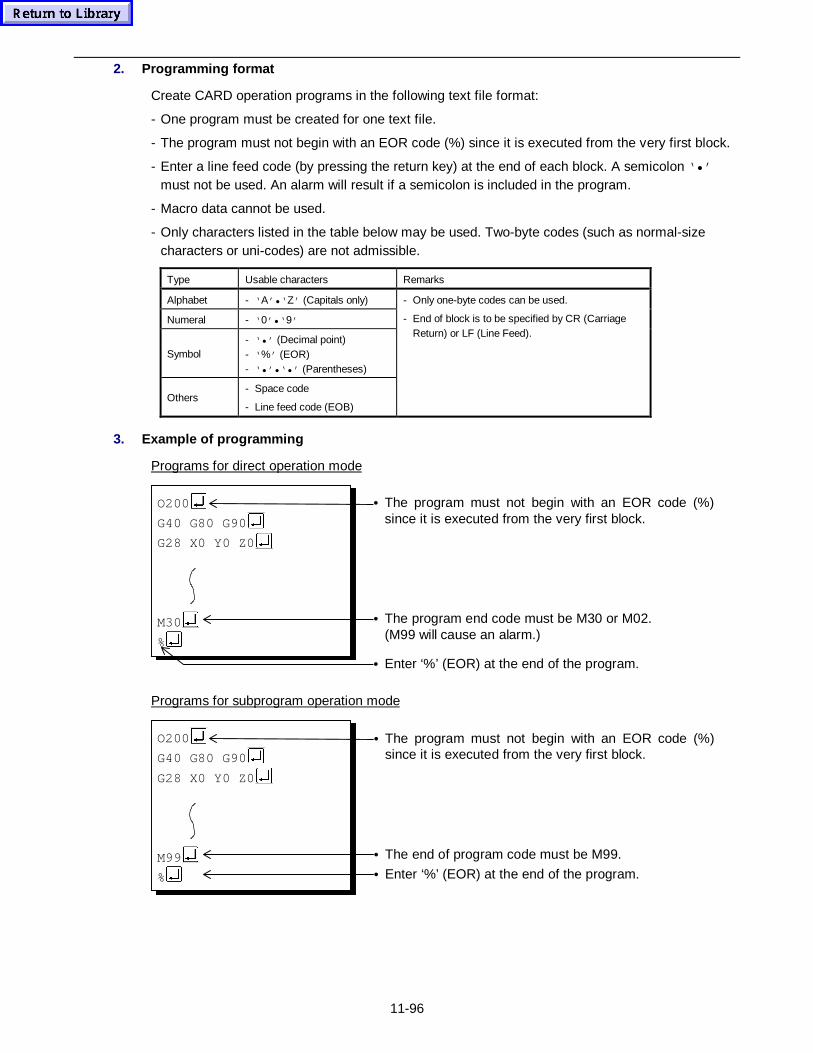
11-96
2. Programm ing fo rmat
Create CARD operation programs in the following text file format:
- One program must be created for one text file.
- The program must not begin with an EOR code (%) since it is executed from the very first block.
- Enter a line feed code (by pressing the return key) at the end of each block. A semicolon ‘•’must not be used. An alarm will result if a semicolon is included in the program.
- Macro data cannot be used.
- Only characters listed in the table below may be used. Two-byte codes (such as normal-sizecharacters or uni-codes) are not admissible.
Type Usable characters Remarks
Alphabet - ‘ A’•‘ Z’ (Capitals only)
Numeral - ‘ 0’•‘ 9’
Symbol- ‘•’ (Decimal point)- ‘ %’ (EOR)- ‘•’•‘•’ (Parentheses)
Others- Space code
- Line feed code (EOB)
- Only one-byte codes can be used.
- End of block is to be specified by CR (CarriageReturn) or LF (Line Feed).
3. Example of programming
Programs for direct operation mode
O200
G40 G80 G90
G28 X0 Y0 Z0
M30
%
• The program must not begin with an EOR code (%)since it is executed from the very first block.
• The program end code must be M30 or M02.
(M99 will cause an alarm.)
• Enter ‘%’ (EOR) at the end of the program.
Programs for subprogram operation mode
O200
G40 G80 G90
G28 X0 Y0 Z0
M99
%
• The program must not begin with an EOR code (%)since it is executed from the very first block.
• The end of program code must be M99.
• Enter ‘%’ (EOR) at the end of the program.
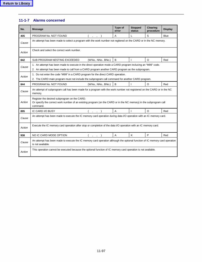
11-97
11-1-7 Alarms concerned
No. Message Type oferror
Stoppedstatus
Clearingprocedure
Display
405 PROGRAM No. NOT FOUND ( , , ) A L S Blue
CauseAn attempt has been made to select a program with the work number not regitered on the CARD or in the NC memory.
ActionCheck and select the correct work number.
842 SUB PROGRAM NESTING EXCEEDED (WNo., NNo., BNo.) B I O Red
Cause1. An attempt has been made to execute in the direct operation mode a CARD program inclucing an “M99” code.
2. An attempt has been made to call from a CARD program another CARD program as the subprogram.
Action1. Do not enter the code “M99” in a CARD program for the direct CARD operation.
2. The CARD main program must not include the subprogram call command for another CARD program.
844 PROGRAM No. NOT FOUND (WNo., NNo., BNo.) B I O Red
CauseAn attempt of subprogram call has been made for a program with the work number not registered on the CARD or in the NCmemory.
ActionRegister the desired subprogram on the CARD.Or specify the correct work number of an existing program (on the CARD or in the NC memory) in the subprogram callcommand.
895 IC CARD I/O BUSY ( , , ) A I O Red
CauseAn attempt has been made to execute the IC memory card operation during data I/O operation with an IC memory card.
ActionExecute the IC memory card operation after stop or completion of the data I/O operation with an IC memory card.
938 NO IC CARD MODE OPTION ( , , ) A K P Red
CauseAn attempt has been made to execute the IC memory card operation although the optional function of IC memory card operationis not available.
ActionThis operation cannot be executed because the optional function of IC memory card operation is not available.
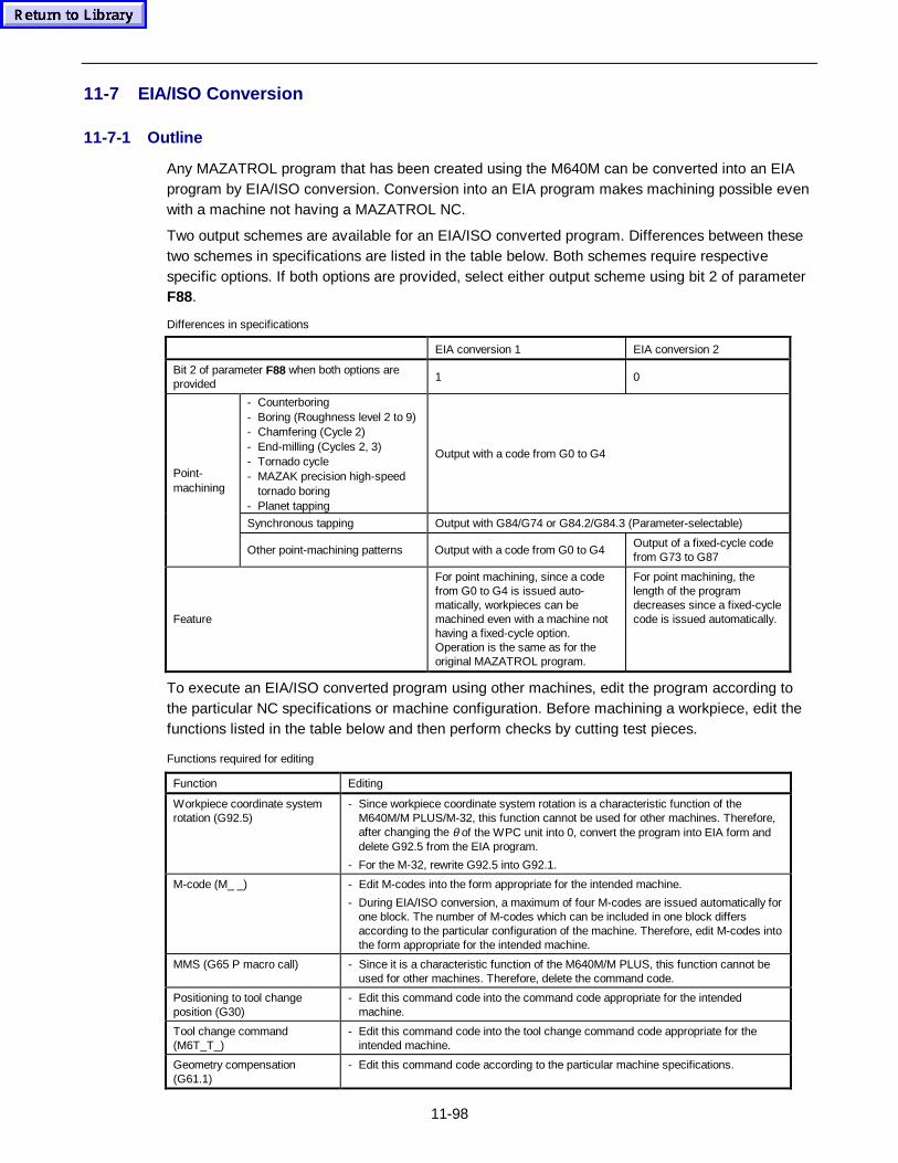
11-98
11-7 EIA/ISO Conversion
11-7-1 Outline
Any MAZATROL program that has been created using the M640M can be converted into an EIAprogram by EIA/ISO conversion. Conversion into an EIA program makes machining possible evenwith a machine not having a MAZATROL NC.
Two output schemes are available for an EIA/ISO converted program. Differences between thesetwo schemes in specifications are listed in the table below. Both schemes require respectivespecific options. If both options are provided, select either output scheme using bit 2 of parameterF88.
Differences in specifications
EIA conversion 1 EIA conversion 2
Bit 2 of parameter F88 when both options areprovided
1 0
- Counterboring- Boring (Roughness level 2 to 9)- Chamfering (Cycle 2)- End-milling (Cycles 2, 3)- Tornado cycle- MAZAK precision high-speed
tornado boring- Planet tapping
Output with a code from G0 to G4
Synchronous tapping Output with G84/G74 or G84.2/G84.3 (Parameter-selectable)
Point-machining
Other point-machining patterns Output with a code from G0 to G4Output of a fixed-cycle codefrom G73 to G87
Feature
For point machining, since a codefrom G0 to G4 is issued auto-matically, workpieces can bemachined even with a machine nothaving a fixed-cycle option.Operation is the same as for theoriginal MAZATROL program.
For point machining, thelength of the programdecreases since a fixed-cyclecode is issued automatically.
To execute an EIA/ISO converted program using other machines, edit the program according tothe particular NC specifications or machine configuration. Before machining a workpiece, edit thefunctions listed in the table below and then perform checks by cutting test pieces.
Functions required for editing
Function Editing
Workpiece coordinate systemrotation (G92.5)
- Since workpiece coordinate system rotation is a characteristic function of theM640M/M PLUS/M-32, this function cannot be used for other machines. Therefore,after changing the θ of the WPC unit into 0, convert the program into EIA form anddelete G92.5 from the EIA program.
- For the M-32, rewrite G92.5 into G92.1.
M-code (M_ _) - Edit M-codes into the form appropriate for the intended machine.
- During EIA/ISO conversion, a maximum of four M-codes are issued automatically forone block. The number of M-codes which can be included in one block differsaccording to the particular configuration of the machine. Therefore, edit M-codes intothe form appropriate for the intended machine.
MMS (G65 P macro call) - Since it is a characteristic function of the M640M/M PLUS, this function cannot beused for other machines. Therefore, delete the command code.
Positioning to tool changeposition (G30)
- Edit this command code into the command code appropriate for the intendedmachine.
Tool change command(M6T_T_)
- Edit this command code into the tool change command code appropriate for theintended machine.
Geometry compensation(G61.1)
- Edit this command code according to the particular machine specifications.
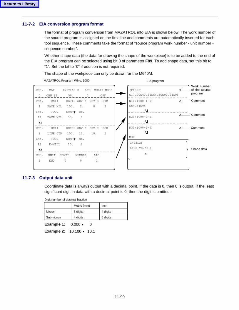
11-99
11-7-2 EIA conversion program format
The format of program conversion from MAZATROL into EIA is shown below. The work number ofthe source program is assigned on the first line and comments are automatically inserted for eachtool sequence. These comments take the format of “source program work number - unit number -sequence number”.
Whether shape data (the data for drawing the shape of the workpiece) is to be added to the end ofthe EIA program can be selected using bit 0 of parameter F89. To add shape data, set this bit to“1”. Set the bit to “0” if addition is not required.
The shape of the workpiece can only be drawn for the M640M.
MAZATROL Program WNo. 1000
(P1000)
G17G00G40G54G64G80G90G94G98
N10(1000-1-1)
G54G64G95
0
N20(1000-2-1)
0
N30(1000-3-0)
0
M30
(G423L2)
(A1X0.Y0.Z0.)
0
%
EIA program
Work numberof the sourceprogram
Comment
Comment
Comment
Shape data
UNo. MAT INITIAL-Z ATC MULTI MOD E
0 CBN ST 50. 0 OFF
UNo. UNIT DEPTH SRV-Z SRV-R BTM
1 FACE MIL 100. 2. 0 3
SNo. TOOL NOM-φ No.
R1
0
FACE MIL 50. 1
UNo. UNIT DETPH SRV-Z SRV-R RGH
2 LINE CTR 100. 10. 10. 2
SNo. TOOL NOM-φ No.
R1
0
E-MILL 10. 2
UNo. UNIT CONTI. NUMBER ATC
3 END 0 0 0
11-7-3 Output data unit
Coordinate data is always output with a decimal point. If the data is 0, then 0 is output. If the leastsignificant digit in data with a decimal point is 0, then the digit is omitted.
Digit number of decimal fraction
Metric (mm) Inch
Micron 3 digits 4 digits
Submicron 4 digits 5 digits
Example 1: 0.000 • 0
Example 2: 10.100 • 10.1
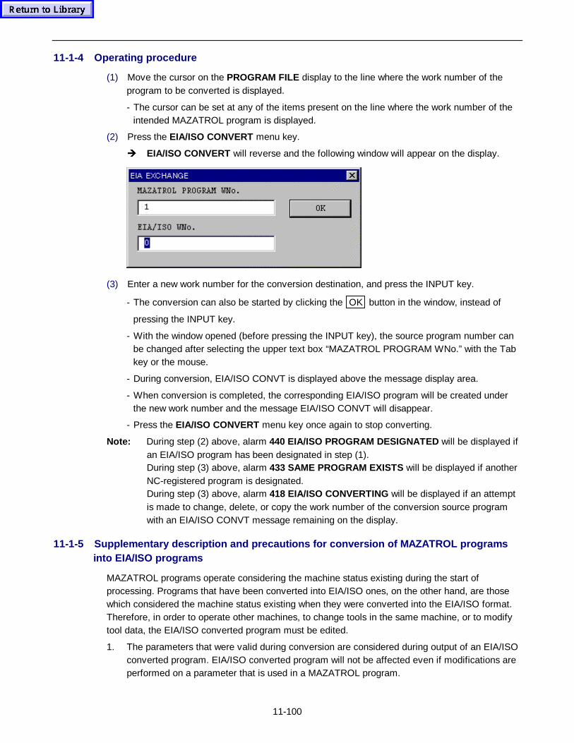
11-100
11-1-4 Operating procedure
(1) Move the cursor on the PROGRAM FILE display to the line where the work number of theprogram to be converted is displayed.
- The cursor can be set at any of the items present on the line where the work number of theintended MAZATROL program is displayed.
(2) Press the EIA/ISO CONVERT menu key.
Î EIA/ISO CONVERT will reverse and the following window will appear on the display.
(3) Enter a new work number for the conversion destination, and press the INPUT key.
- The conversion can also be started by clicking the OK button in the window, instead of
pressing the INPUT key.
- With the window opened (before pressing the INPUT key), the source program number canbe changed after selecting the upper text box “MAZATROL PROGRAM WNo.” with the Tabkey or the mouse.
- During conversion, EIA/ISO CONVT is displayed above the message display area.
- When conversion is completed, the corresponding EIA/ISO program will be created underthe new work number and the message EIA/ISO CONVT will disappear.
- Press the EIA/ISO CONVERT menu key once again to stop converting.
Note: During step (2) above, alarm 440 EIA/ISO PROGRAM DESIGNATED will be displayed ifan EIA/ISO program has been designated in step (1).During step (3) above, alarm 433 SAME PROGRAM EXISTS will be displayed if anotherNC-registered program is designated.During step (3) above, alarm 418 EIA/ISO CONVERTING will be displayed if an attemptis made to change, delete, or copy the work number of the conversion source programwith an EIA/ISO CONVT message remaining on the display.
11-1-5 Supplementary description and pr ecautions for conversion of MAZATROL programsinto EIA/ISO programs
MAZATROL programs operate considering the machine status existing during the start ofprocessing. Programs that have been converted into EIA/ISO ones, on the other hand, are thosewhich considered the machine status existing when they were converted into the EIA/ISO format.Therefore, in order to operate other machines, to change tools in the same machine, or to modifytool data, the EIA/ISO converted program must be edited.
1. The parameters that were valid during conversion are considered during output of an EIA/ISOconverted program. EIA/ISO converted program will not be affected even if modifications areperformed on a parameter that is used in a MAZATROL program.
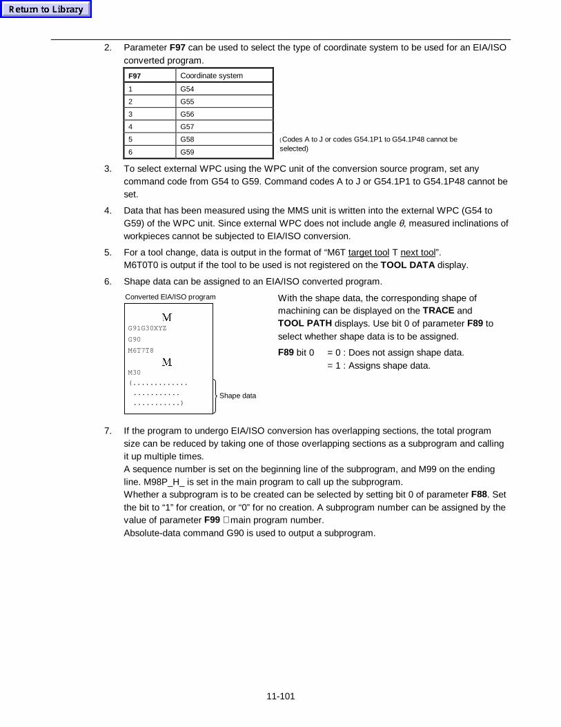
11-101
2. Parameter F97 can be used to select the type of coordinate system to be used for an EIA/ISOconverted program.
F97 Coordinate system
1 G54
2 G55
3 G56
4 G57
5 G58
6 G59
( Codes A to J or codes G54.1P1 to G54.1P48 cannot be selected)
3. To select external WPC using the WPC unit of the conversion source program, set anycommand code from G54 to G59. Command codes A to J or G54.1P1 to G54.1P48 cannot beset.
4. Data that has been measured using the MMS unit is written into the external WPC (G54 toG59) of the WPC unit. Since external WPC does not include angle θ, measured inclinations ofworkpieces cannot be subjected to EIA/ISO conversion.
5. For a tool change, data is output in the format of “M6T target tool T next tool”.M6T0T0 is output if the tool to be used is not registered on the TOOL DATA display.
6. Shape data can be assigned to an EIA/ISO converted program.
0G91G30XYZ
G90
M6T7T8
0M30
(.............
...........
...........)Shape data
Converted EIA/ISO program With the shape data, the corresponding shape ofmachining can be displayed on the TRACE andTOOL PATH displays. Use bit 0 of parameter F89 toselect whether shape data is to be assigned.
F89 bit 0 = 0 : Does not assign shape data.= 1 : Assigns shape data.
7. If the program to undergo EIA/ISO conversion has overlapping sections, the total programsize can be reduced by taking one of those overlapping sections as a subprogram and callingit up multiple times.A sequence number is set on the beginning line of the subprogram, and M99 on the endingline. M98P_H_ is set in the main program to call up the subprogram.Whether a subprogram is to be created can be selected by setting bit 0 of parameter F88. Setthe bit to “1” for creation, or “0” for no creation. A subprogram number can be assigned by thevalue of parameter F99 + main program number.Absolute-data command G90 is used to output a subprogram.
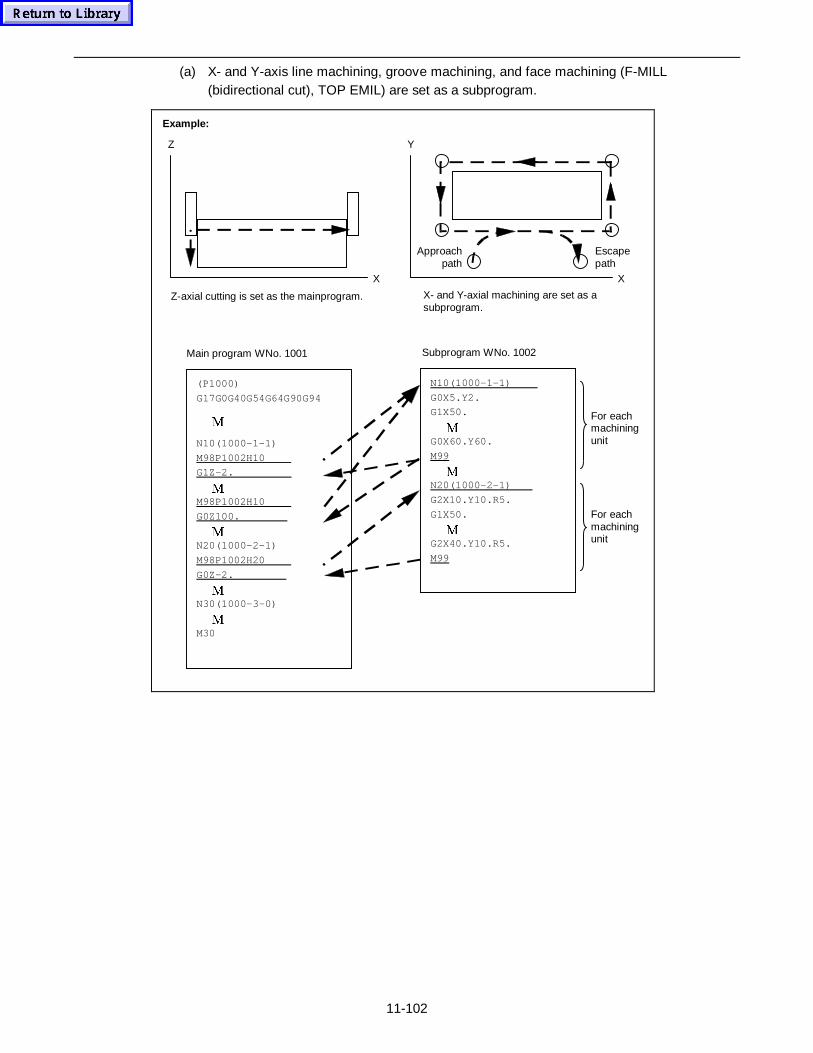
11-102
(a) X- and Y-axis line machining, groove machining, and face machining (F-MILL(bidirectional cut), TOP EMIL) are set as a subprogram.
Z
X
Y
(P1000)
G17G0G40G54G64G90G94
0
N10(1000-1-1)
M98P1002H10
G1Z-2.
0M98P1002H10
G0Z100.
0N20(1000-2-1)
M98P1002H20
G0Z-2.
0N30(1000-3-0)
0M30
N10(1000-1-1)
G0X5.Y2.
G1X50.
0G0X60.Y60.
M99
0N20(1000-2-1)
G2X10.Y10.R5.
G1X50.
0G2X40.Y10.R5.
M99
X
Z-axial cutting is set as the mainprogram. X- and Y-axial machining are set as asubprogram.
Main program WNo. 1001 Subprogram WNo. 1002
Approach path
Escapepath
For eachmachiningunit
For eachmachiningunit
Example:
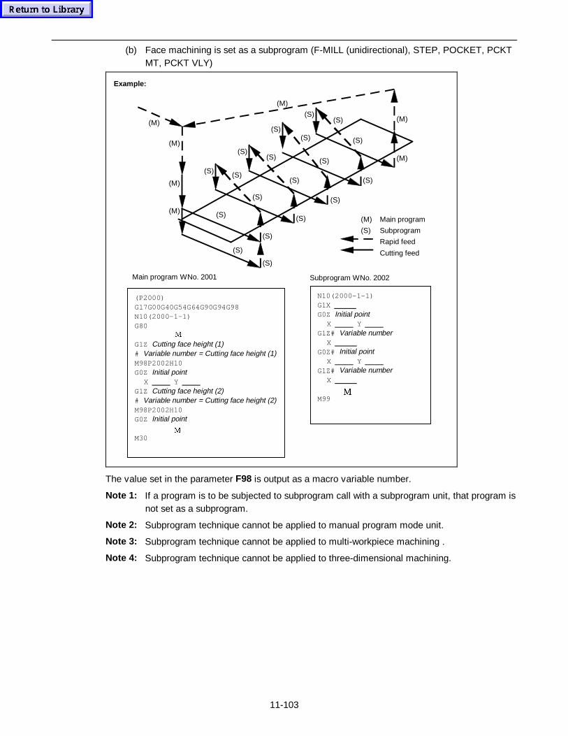
11-103
(b) Face machining is set as a subprogram (F-MILL (unidirectional), STEP, POCKET, PCKTMT, PCKT VLY)
(P2000)G17G00G40G54G64G90G94G98N10(2000-1-1)G80 G1Z Cutting face height (1)# Variable number = Cutting face height (1)M98P2002H10G0Z Initial point X Y G1Z Cutting face height (2)# Variable number = Cutting face height (2)M98P2002H10G0Z Initial point M30
Example:
0
0
N10(2000-1-1)G1X G0Z Initial point X Y G1Z# Variable number X G0Z# Initial point X Y G1Z# Variable number X
M990
Main program WNo. 2001 Subprogram WNo. 2002
(M) Main program
(S) Subprogram
Rapid feed
Cutting feed(S)
(S)
(S)
(S)
(S)
(S)
(S)
(S)
(S)
(S)
(S)
(S)
(S)
(S)
(S)(S)
(S)
(S)
(S)
(M)
(M)
(M)
(M)
(M)
(M)
(M)
The value set in the parameter F98 is output as a macro variable number.
Note 1: If a program is to be subjected to subprogram call with a subprogram unit, that program isnot set as a subprogram.
Note 2: Subprogram technique cannot be applied to manual program mode unit.
Note 3: Subprogram technique cannot be applied to multi-workpiece machining .
Note 4: Subprogram technique cannot be applied to three-dimensional machining.
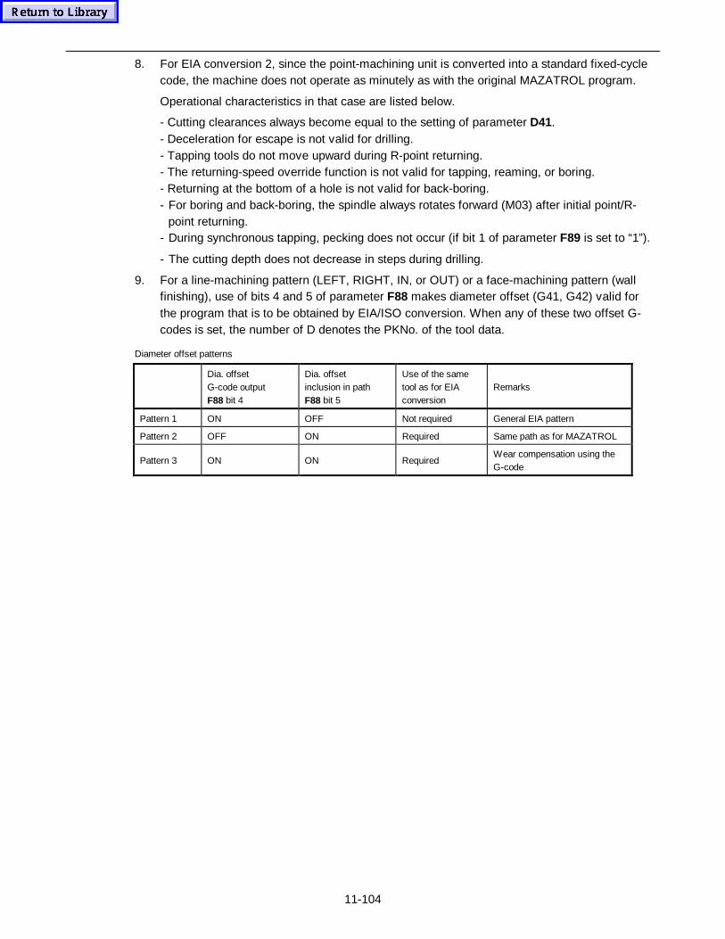
11-104
8. For EIA conversion 2, since the point-machining unit is converted into a standard fixed-cyclecode, the machine does not operate as minutely as with the original MAZATROL program.
Operational characteristics in that case are listed below.
- Cutting clearances always become equal to the setting of parameter D41.- Deceleration for escape is not valid for drilling.- Tapping tools do not move upward during R-point returning.- The returning-speed override function is not valid for tapping, reaming, or boring.- Returning at the bottom of a hole is not valid for back-boring.- For boring and back-boring, the spindle always rotates forward (M03) after initial point/R-
point returning.- During synchronous tapping, pecking does not occur (if bit 1 of parameter F89 is set to “1”).
- The cutting depth does not decrease in steps during drilling.
9. For a line-machining pattern (LEFT, RIGHT, IN, or OUT) or a face-machining pattern (wallfinishing), use of bits 4 and 5 of parameter F88 makes diameter offset (G41, G42) valid forthe program that is to be obtained by EIA/ISO conversion. When any of these two offset G-codes is set, the number of D denotes the PKNo. of the tool data.
Diameter offset patterns
Dia. offsetG-code outputF88 bit 4
Dia. offsetinclusion in pathF88 bit 5
Use of the sametool as for EIAconversion
Remarks
Pattern 1 ON OFF Not required General EIA pattern
Pattern 2 OFF ON Required Same path as for MAZATROL
Pattern 3 ON ON RequiredWear compensation using theG-code
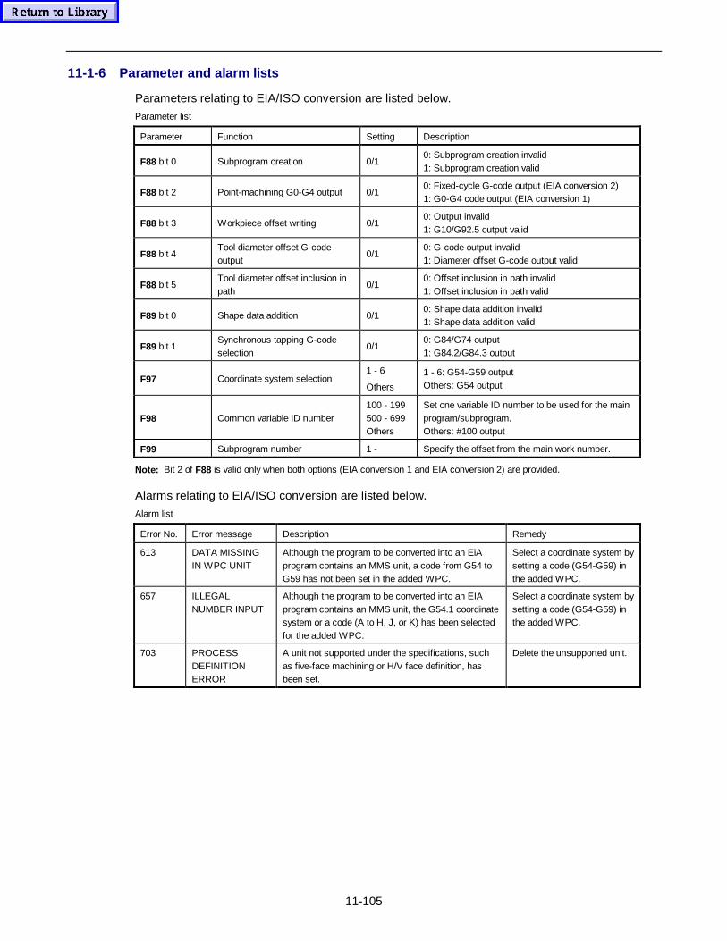
11-105
11-1-6 Parameter and alarm lists
Parameters relating to EIA/ISO conversion are listed below.
Parameter list
Parameter Function Setting Description
F88 bit 0 Subprogram creation 0/10: Subprogram creation invalid1: Subprogram creation valid
F88 bit 2 Point-machining G0-G4 output 0/10: Fixed-cycle G-code output (EIA conversion 2)1: G0-G4 code output (EIA conversion 1)
F88 bit 3 Workpiece offset writing 0/10: Output invalid1: G10/G92.5 output valid
F88 bit 4Tool diameter offset G-codeoutput
0/10: G-code output invalid1: Diameter offset G-code output valid
F88 bit 5Tool diameter offset inclusion inpath
0/10: Offset inclusion in path invalid1: Offset inclusion in path valid
F89 bit 0 Shape data addition 0/10: Shape data addition invalid1: Shape data addition valid
F89 bit 1Synchronous tapping G-codeselection
0/10: G84/G74 output1: G84.2/G84.3 output
F97 Coordinate system selection1 - 6
Others
1 - 6: G54-G59 outputOthers: G54 output
F98 Common variable ID number100 - 199500 - 699Others
Set one variable ID number to be used for the mainprogram/subprogram.Others: #100 output
F99 Subprogram number 1 - Specify the offset from the main work number.
Note: Bit 2 of F88 is valid only when both options (EIA conversion 1 and EIA conversion 2) are provided.
Alarms relating to EIA/ISO conversion are listed below.
Alarm list
Error No. Error message Description Remedy
613 DATA MISSINGIN WPC UNIT
Although the program to be converted into an EiAprogram contains an MMS unit, a code from G54 toG59 has not been set in the added WPC.
Select a coordinate system bysetting a code (G54-G59) inthe added WPC.
657 ILLEGALNUMBER INPUT
Although the program to be converted into an EIAprogram contains an MMS unit, the G54.1 coordinatesystem or a code (A to H, J, or K) has been selectedfor the added WPC.
Select a coordinate system bysetting a code (G54-G59) inthe added WPC.
703 PROCESSDEFINITIONERROR
A unit not supported under the specifications, suchas five-face machining or H/V face definition, hasbeen set.
Delete the unsupported unit.
Section 4:
Automatic Operation

Notes:
Fusion 640M Auto Operation
SAFETY PRECAUTIONS S-1....................................................................
Lockout Procedure S-4............................................................................................
Installation Precautions S-5.....................................................................................
Warnings S-8...........................................................................................................
1 AUTOMATIC OPERATION EXECUTION 1-1.........................................
1-1 Automatic Operation Execution Procedure 1-1.................................................
1-2 Types of Automatic Operation Mode 1-3...........................................................
1-2-1 Automatic operation 1-4...................................................................................................
1-2-2 Restart operation 1-8........................................................................................................
1-1-3 MDI operation 1-16.............................................................................................................
2 SELECTING EXECUTION CONDITIONS 2-1........................................
2-1 Optional Stop 2-1..............................................................................................
2-1-1 Procedure 2-1...................................................................................................................
2-1-2 Description 2-2.................................................................................................................
2-2 Dry Run 2-2.......................................................................................................
2-2-1 Procedure 2-2...................................................................................................................
2-2-2 Description 2-3.................................................................................................................
2-3 Machine Lock 2-3..............................................................................................
2-3-1 Procedure 2-3...................................................................................................................
2-3-2 Description 2-3.................................................................................................................
2-4 Work Light 2-3...................................................................................................
2-4-1 Procedure 2-3...................................................................................................................
2-5 Block Skip 2-4...................................................................................................
2-5-1 Procedure 2-4...................................................................................................................
2-5-2 Description 2-4.................................................................................................................
2-6 Single Block 2-4................................................................................................
2-6-1 Procedure 2-4...................................................................................................................
2-6-2 Description 2-4.................................................................................................................
2-7 Comparison Stop 2-5........................................................................................
2-7-1 Setting procedure 2-5.......................................................................................................
2-7-2 Description 2-5.................................................................................................................
2-8 Z-axis Cancel 2-7..............................................................................................
2-8-1 Procedure 2-7...................................................................................................................
2-8-2 Description 2-7.................................................................................................................
2-9 MST Lock 2-7....................................................................................................
2-9-1 Procedure 2-8...................................................................................................................
2-9-2 Description 2-8.................................................................................................................
2-10 ATC Stop 2-8...................................................................................................
2-11 TUNING SV PARAM 2-8.................................................................................
2-11-1 Operation procedure 2-9................................................................................................
2-11-2 Function description 2-10.................................................................................................
3 CHANGING THE CUTTING CONDITIONS 3-1......................................
3-1 Rapid Feed Override 3-1...................................................................................
3-1-1 Procedure 3-1...................................................................................................................
3-2 Cutting Feed Override 3-2.................................................................................
3-2-1 Procedure 3-2...................................................................................................................
3-3 Spindle Speed Override 3-3..............................................................................
3-3-1 Procedure 3-3...................................................................................................................
3-4 VFC Function 3-4..............................................................................................
3-4-1 Procedure 3-4...................................................................................................................
3-4-2 Description 3-4.................................................................................................................
3-5 AFC Function (Option) 3-6................................................................................
3-5-1 Setting the desired current load value 3-7........................................................................
3-5-2 Tools available with AFC and AFC supervisory modes 3-8.............................................
3-5-3 Functional operation 3-8...................................................................................................
4 STOPPING AUTOMATIC OPERATION 4-1...........................................
4-1 Emergency Stop 4-1..........................................................................................
4-1-1 Emergency Stop 4-1.........................................................................................................
4-1-2 Releasing the emergency stop status 4-1........................................................................
4-2 Reset 4-2...........................................................................................................
4-3 Feed Hold 4-2....................................................................................................
4-4 Stopping by Changeover to a Manual Operation Mode 4-3..............................
4-5 Single-block Stop 4-3........................................................................................
4-5-1 Single-block stop by changing within automatic operation modes 4-3.............................
4-5-2 Single-block stop using the SINGLE BLOCK key 4-4......................................................
4-6 Program Stop 4-4..............................................................................................
4-7 Stopping by Turning the Power Off 4-4.............................................................
5 MANUAL INTERRUPTION 5-1...............................................................
5-1 Handle Interruption (Option) 5-1........................................................................
5-1-1 Handle interruption 5-1.....................................................................................................
5-1-2 Clearing the manual handle interruption 5-1....................................................................
5-2 TPS Function 5-2..............................................................................................
5-2-1 Storing the data of only the stop point of automatic operation 5-2...................................
5-2-2 Storing the data of both the stop point of automatic operation and the passage 5-3.......
5-2-3 Storing the data of only the passage point(s) existing during manual interruption 5-4.....
5-2-4 General remarks on TPS function 5-4..............................................................................
6 OPERATIONS POSSIBLE DURING AUTOMATIC OPERATION 6-1...
6-1 Data Rewriting 6-1.............................................................................................
6-1-1 Data writing conditions 6-1...............................................................................................

Notes:
1-1
1 AUTOMATIC OPERATION EXECUTION
Automatic operation of the machine according to previously created programs and data is referredto as automatic operation.
Automatic operation becomes possible just by selecting the program to be executed and thenstarting it, provided that errors are not present in the program or data. No other operations arerequired.
During automatic operation, however, since it is possible to stop the machine action, to change thecutting conditions, or to generate hand interrupts, these operations may become necessary.
This chapter describes automatic operation execution procedures.
1-1 Automatic Operation Execution Procedure
The description given below assumes that tooling, machine adjustment, programming, andautomatic operation data setting have already been completed. Here, general working proceduresto be used after completion of those operational setup jobs are described.
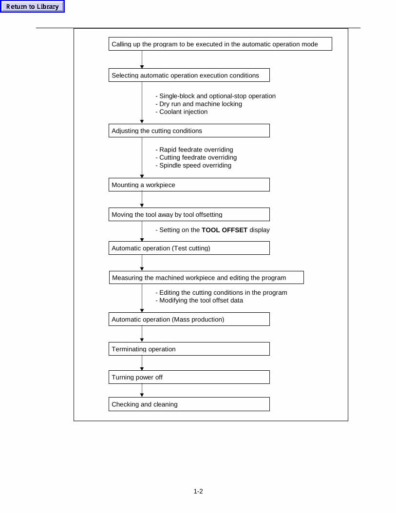
1-2
Calling up the program to be executed in the automatic operation mode
- Single-block and optional-stop operation- Dry run and machine locking- Coolant injection
Selecting automatic operation execution conditions
- Rapid feedrate overriding- Cutting feedrate overriding- Spindle speed overriding
Adjusting the cutting conditions
Mounting a workpiece
- Setting on the TOOL OFFSET display
Automatic operation (Test cutting)
Moving the tool away by tool offsetting
- Editing the cutting conditions in the program- Modifying the tool offset data
Measuring the machined workpiece and editing the program
Automatic operation (Mass production)
Terminating operation
Turning power off
Checking and cleaning
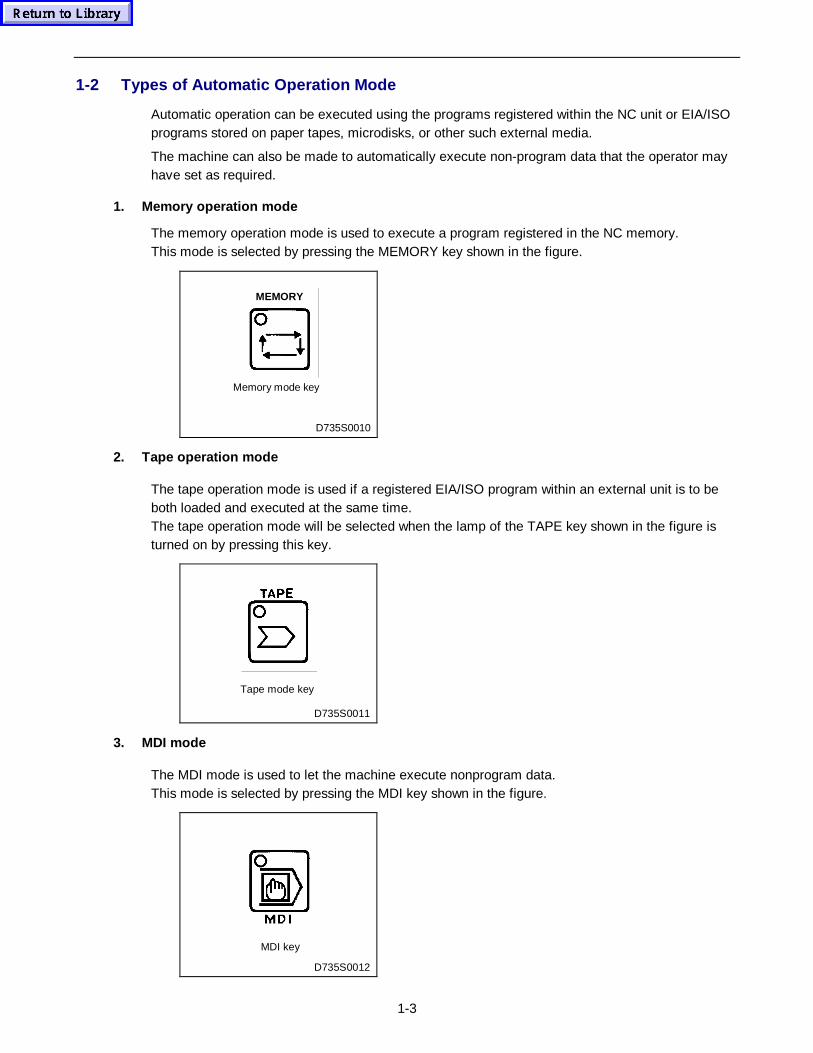
1-3
1-2 Types of Automatic Operation Mode
Automatic operation can be executed using the programs registered within the NC unit or EIA/ISOprograms stored on paper tapes, microdisks, or other such external media.
The machine can also be made to automatically execute non-program data that the operator mayhave set as required.
1. Memory operat ion mode
The memory operation mode is used to execute a program registered in the NC memory.This mode is selected by pressing the MEMORY key shown in the figure.
D735S0010
MEMORY
Memory mode key
2. Tape operat ion mode
The tape operation mode is used if a registered EIA/ISO program within an external unit is to beboth loaded and executed at the same time.The tape operation mode will be selected when the lamp of the TAPE key shown in the figure isturned on by pressing this key.
Tape mode key
D735S0011
3. MDI mode
The MDI mode is used to let the machine execute nonprogram data.This mode is selected by pressing the MDI key shown in the figure.
MDI key
D735S0012
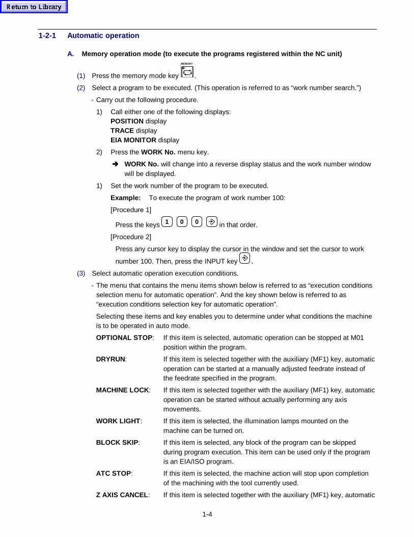
1-4
1-2-1 Automatic operation
A. Memory operat ion mode (to execute the programs registered wit hin the NC unit)
(1) Press the memory mode key
MEMORY
.
(2) Select a program to be executed. (This operation is referred to as “work number search.”)
- Carry out the following procedure.
1) Call either one of the following displays:POSITION displayTRACE displayEIA MONITOR display
2) Press the WORK No. menu key.
Î WORK No. will change into a reverse display status and the work number windowwill be displayed.
1) Set the work number of the program to be executed.
Example: To execute the program of work number 100:
[Procedure 1]
Press the keys 1 0 0 in that order.
[Procedure 2]
Press any cursor key to display the cursor in the window and set the cursor to work
number 100. Then, press the INPUT key .
(3) Select automatic operation execution conditions.
- The menu that contains the menu items shown below is referred to as “execution conditionsselection menu for automatic operation”. And the key shown below is referred to as“execution conditions selection key for automatic operation”.
Selecting these items and key enables you to determine under what conditions the machineis to be operated in auto mode.
OPTIONAL STOP : If this item is selected, automatic operation can be stopped at M01position within the program.
DRYRUN: If this item is selected together with the auxiliary (MF1) key, automaticoperation can be started at a manually adjusted feedrate instead ofthe feedrate specified in the program.
MACHINE LOCK : If this item is selected together with the auxiliary (MF1) key, automaticoperation can be started without actually performing any axismovements.
WORK LIGHT : If this item is selected, the illumination lamps mounted on themachine can be turned on.
BLOCK SKIP : If this item is selected, any block of the program can be skippedduring program execution. This item can be used only if the programis an EIA/ISO program.
ATC STOP: If this item is selected, the machine action will stop upon completionof the machining with the tool currently used.
Z AXIS CANCEL : If this item is selected together with the auxiliary (MF1) key, automatic
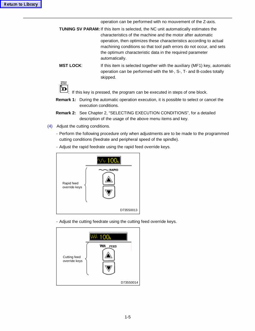
1-5
operation can be performed with no mouvement of the Z-axis.
TUNING SV PARAM: If this item is selected, the NC unit automatically estimates thecharacteristics of the machine and the motor after automaticoperation, then optimizes these characteristics according to actualmachining conditions so that tool path errors do not occur, and setsthe optimum characteristic data in the required parameterautomatically.
MST LOCK : If this item is selected together with the auxiliary (MF1) key, automaticoperation can be performed with the M-, S-, T- and B-codes totallyskipped.
SINGLEBLOCK
: If this key is pressed, the program can be executed in steps of one block.
Remark 1: During the automatic operation execution, it is possible to select or cancel theexecution conditions.
Remark 2: See Chapter 2, “SELECTING EXECUTION CONDITIONS”, for a detaileddescription of the usage of the above menu items and key.
(4) Adjust the cutting conditions.
- Perform the following procedure only when adjustments are to be made to the programmedcutting conditions (feedrate and peripheral speed of the spindle).
- Adjust the rapid feedrate using the rapid feed override keys.
Rapid feedoverride keys
D735S0013
- Adjust the cutting feedrate using the cutting feed override keys.
Cutting feedoverride keys
D735S0014
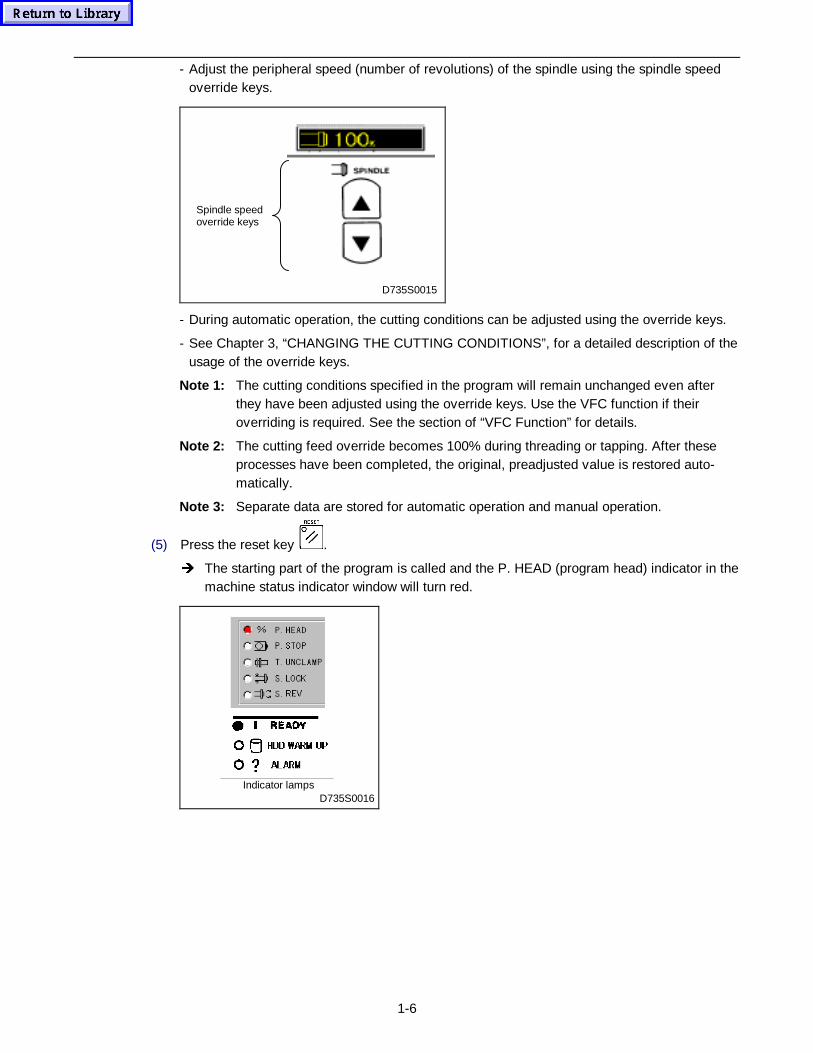
1-6
- Adjust the peripheral speed (number of revolutions) of the spindle using the spindle speedoverride keys.
D735S0015
Spindle speedoverride keys
- During automatic operation, the cutting conditions can be adjusted using the override keys.
- See Chapter 3, “CHANGING THE CUTTING CONDITIONS”, for a detailed description of theusage of the override keys.
Note 1: The cutting conditions specified in the program will remain unchanged even afterthey have been adjusted using the override keys. Use the VFC function if theiroverriding is required. See the section of “VFC Function” for details.
Note 2: The cutting feed override becomes 100% during threading or tapping. After theseprocesses have been completed, the original, preadjusted value is restored auto-matically.
Note 3: Separate data are stored for automatic operation and manual operation.
(5) Press the reset key .
Î The starting part of the program is called and the P. HEAD (program head) indicator in themachine status indicator window will turn red.
Indicator lampsD735S0016
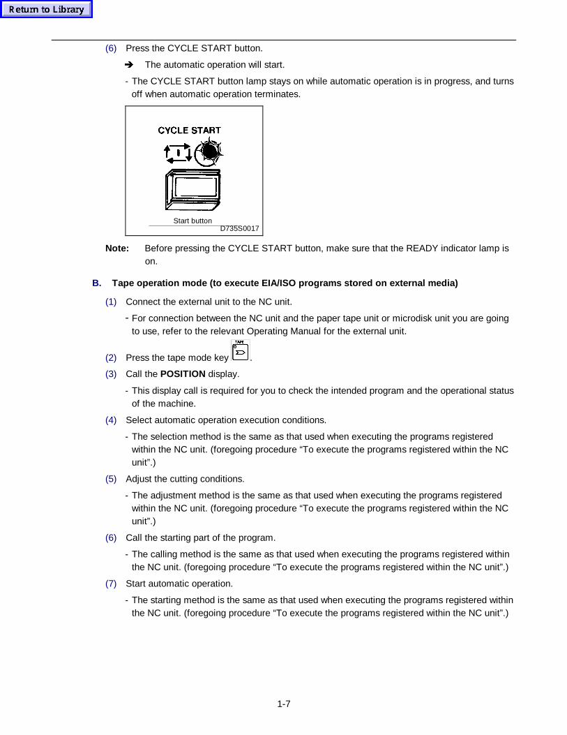
1-7
(6) Press the CYCLE START button.
Î The automatic operation will start.
- The CYCLE START button lamp stays on while automatic operation is in progress, and turnsoff when automatic operation terminates.
Start buttonD735S0017
Note: Before pressing the CYCLE START button, make sure that the READY indicator lamp ison.
B. Tape operat ion mode (to execute EIA/ISO programs stored on external media)
(1) Connect the external unit to the NC unit.
- For connection between the NC unit and the paper tape unit or microdisk unit you are goingto use, refer to the relevant Operating Manual for the external unit.
(2) Press the tape mode key .
(3) Call the POSITION display.
- This display call is required for you to check the intended program and the operational statusof the machine.
(4) Select automatic operation execution conditions.
- The selection method is the same as that used when executing the programs registeredwithin the NC unit. (foregoing procedure “To execute the programs registered within the NCunit”.)
(5) Adjust the cutting conditions.
- The adjustment method is the same as that used when executing the programs registeredwithin the NC unit. (foregoing procedure “To execute the programs registered within the NCunit”.)
(6) Call the starting part of the program.
- The calling method is the same as that used when executing the programs registered withinthe NC unit. (foregoing procedure “To execute the programs registered within the NC unit”.)
(7) Start automatic operation.
- The starting method is the same as that used when executing the programs registered withinthe NC unit. (foregoing procedure “To execute the programs registered within the NC unit”.)
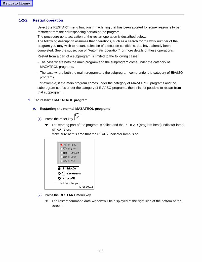
1-8
1-2-2 Restart operation
Select the RESTART menu function if machining that has been aborted for some reason is to berestarted from the corresponding portion of the program.The procedure up to activation of the restart operation is described below.The following description assumes that operations, such as a search for the work number of theprogram you may wish to restart, selection of execution conditions, etc. have already beencompleted. See the subsection of “Automatic operation” for more details of these operations.
Restart from a part of a subprogram is limited to the following cases:
- The case where both the main program and the subprogram come under the category ofMAZATROL programs.
- The case where both the main program and the subprogram come under the category of EIA/ISOprograms.
For example, if the main program comes under the category of MAZATROL programs and thesubprogram comes under the category of EIA/ISO programs, then it is not possible to restart fromthat subprogram.
1. To restart a MAZATROL program
A. Restart ing the no rmal MAZATROL programs
(1) Press the reset key .
Î The starting part of the program is called and the P. HEAD (program head) indicator lampwill come on.Make sure at this time that the READY indicator lamp is on.
Indicator lampsD735S0016
(2) Press the RESTART menu key.
Î The restart command data window will be displayed at the right side of the bottom of thescreen.
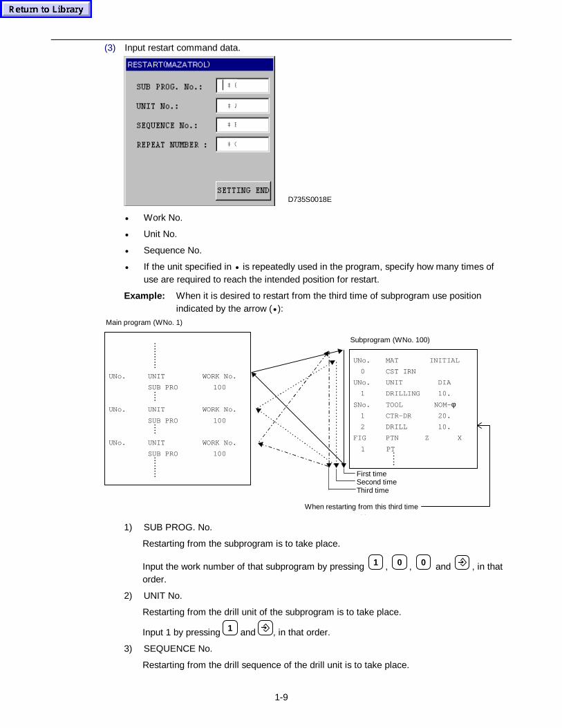
1-9
(3) Input restart command data.
‡ @
‡ C
‡ B
‡ A
D735S0018E
• Work No.
• Unit No.
• Sequence No.
• If the unit specified in • is repeatedly used in the program, specify how many times ofuse are required to reach the intended position for restart.
Example: When it is desired to restart from the third time of subprogram use positionindicated by the arrow (• ):
UNo. UNIT WORK No.
SUB PRO 100
UNo. UNIT WORK No.
SUB PRO 100
UNo. UNIT WORK No.
SUB PRO 100
Main program (WNo. 1)
UNo. MAT INITIAL
0 CST IRN
UNo. UNIT DIA
1 DRILLING 10.
SNo. TOOL NOM-φ 1 CTR-DR 20.
2 DRILL 10.
FIG PTN Z X
1 PT
Subprogram (WNo. 100)
When restarting from this third time
i i
First timeSecond timeThird time
.......... ....
.... ........
…..
1) SUB PROG. No.
Restarting from the subprogram is to take place.
Input the work number of that subprogram by pressing 1 , 0 , 0 and , in thatorder.
2) UNIT No.
Restarting from the drill unit of the subprogram is to take place.
Input 1 by pressing 1 and , in that order.
3) SEQUENCE No.
Restarting from the drill sequence of the drill unit is to take place.
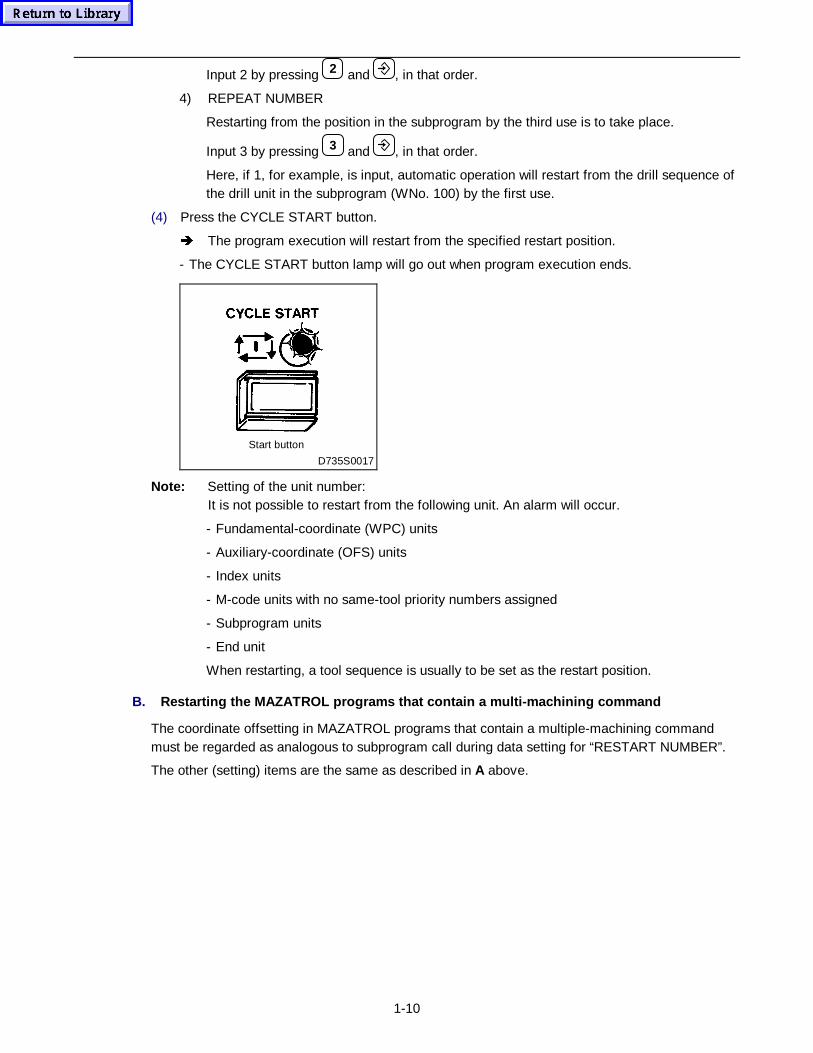
1-10
Input 2 by pressing 2 and , in that order.
4) REPEAT NUMBER
Restarting from the position in the subprogram by the third use is to take place.
Input 3 by pressing 3 and , in that order.
Here, if 1, for example, is input, automatic operation will restart from the drill sequence ofthe drill unit in the subprogram (WNo. 100) by the first use.
(4) Press the CYCLE START button.
Î The program execution will restart from the specified restart position.
- The CYCLE START button lamp will go out when program execution ends.
Start button
D735S0017
Note: Setting of the unit number:It is not possible to restart from the following unit. An alarm will occur.
- Fundamental-coordinate (WPC) units
- Auxiliary-coordinate (OFS) units
- Index units
- M-code units with no same-tool priority numbers assigned
- Subprogram units
- End unit
When restarting, a tool sequence is usually to be set as the restart position.
B. Restart ing the MAZATROL prog rams that contain a multi-mac hining co mmand
The coordinate offsetting in MAZATROL programs that contain a multiple-machining commandmust be regarded as analogous to subprogram call during data setting for “RESTART NUMBER”.
The other (setting) items are the same as described in A above.
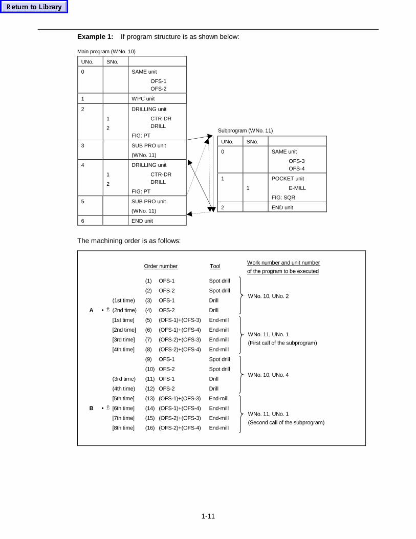
1-11
Example 1: If program structure is as shown below:
Main program (WNo. 10)
UNo. SNo.
0 SAME unit
OFS-1OFS-2
1 WPC unit
2
1
2
DRILLING unit
CTR-DRDRILL
FIG: PT
3 SUB PRO unit
(WNo. 11)
4
1
2
DRILLING unit
CTR-DRDRILL
FIG: PT
5 SUB PRO unit
(WNo. 11)
6 END unit
The machining order is as follows:
(1) OFS-1 Spot drill
(2) OFS-2 Spot drill
(1st time) (3) OFS-1 Drill
A • Ë (2nd time) (4) OFS-2 Drill
[1st time] (5) (OFS-1)+(OFS-3) End-mill
[2nd time] (6) (OFS-1)+(OFS-4) End-mill
[3rd time] (7) (OFS-2)+(OFS-3) End-mill
[4th time] (8) (OFS-2)+(OFS-4) End-mill
(9) OFS-1 Spot drill
(10) OFS-2 Spot drill
(3rd time) (11) OFS-1 Drill
(4th time) (12) OFS-2 Drill
[5th time] (13) (OFS-1)+(OFS-3) End-mill
B • Ë [6th time] (14) (OFS-1)+(OFS-4) End-mill
[7th time] (15) (OFS-2)+(OFS-3) End-mill
[8th time] (16) (OFS-2)+(OFS-4) End-mill
WNo. 11, UNo. 1
(First call of the subprogram)
Work number and unit number
of the program to be executedOrder number Tool
WNo. 11, UNo. 1
(Second call of the subprogram)
WNo. 10, UNo. 2
WNo. 10, UNo. 4
UNo. SNo.
0 SAME unit
OFS-3OFS-4
1
1
POCKET unit
E-MILL
FIG: SQR
2 END unit
Subprogram (WNo. 11)
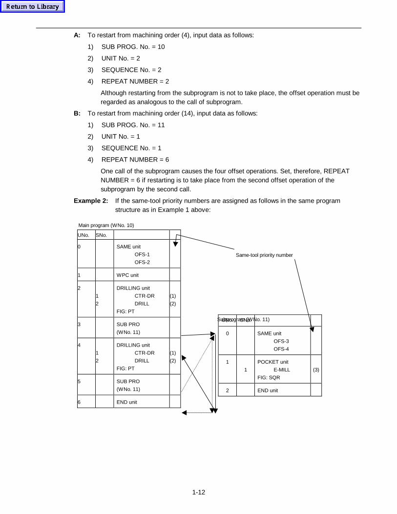
1-12
A: To restart from machining order (4), input data as follows:
1) SUB PROG. No. = 10
2) UNIT No. = 2
3) SEQUENCE No. = 2
4) REPEAT NUMBER = 2
Although restarting from the subprogram is not to take place, the offset operation must beregarded as analogous to the call of subprogram.
B: To restart from machining order (14), input data as follows:
1) SUB PROG. No. = 11
2) UNIT No. = 1
3) SEQUENCE No. = 1
4) REPEAT NUMBER = 6
One call of the subprogram causes the four offset operations. Set, therefore, REPEATNUMBER = 6 if restarting is to take place from the second offset operation of thesubprogram by the second call.
Example 2: If the same-tool priority numbers are assigned as follows in the same programstructure as in Example 1 above:
Main program (WNo. 10)
UNo. SNo.
0 SAME unit
OFS-1
OFS-2
1 WPC unit
2
1
2
DRILLING unit
CTR-DR
DRILL
FIG: PT
(1)
(2)
3 SUB PRO
(WNo. 11)
4
1
2
DRILLING unit
CTR-DR
DRILL
FIG: PT
(1)
(2)
5 SUB PRO
(WNo. 11)
6 END unit
Subprogram (WNo. 11)
Same-tool priority number
UNo. SNo.
0 SAME unit
OFS-3
OFS-4
1
1
POCKET unit
E-MILL
FIG: SQR
(3)
2 END unit
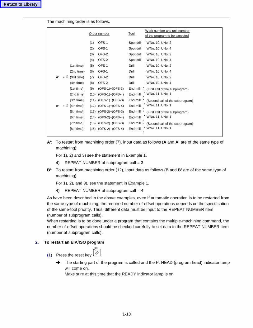
1-13
The machining order is as follows.
(1) OFS-1 Spot drill WNo. 10, UNo. 2
(2) OFS-1 Spot drill WNo. 10, UNo. 4
(3) OFS-2 Spot drill WNo. 10, UNo. 2
(4) OFS-2 Spot drill WNo. 10, UNo. 4
(1st time) (5) OFS-1 Drill WNo. 10, UNo. 2
(2nd time) (6) OFS-1 Drill WNo. 10, UNo. 4
A’ • Ë (3rd time) (7) OFS-2 Drill WNo. 10, UNo. 2
(4th time) (8) OFS-2 Drill WNo. 10, UNo. 4
[1st time] (9) (OFS-1)+(OFS-3) End-mill
[2nd time] (10) (OFS-1)+(OFS-4) End-mill
(First call of the subprogram)WNo. 11, UNo. 1
[3rd time] (11) (OFS-1)+(OFS-3) End-mill
B’ • Ë [4th time] (12) (OFS-1)+(OFS-4) End-mill
(Second call of the subprogram)WNo. 11, UNo. 1
[5th time] (13) (OFS-2)+(OFS-3) End-mill
[6th time] (14) (OFS-2)+(OFS-4) End-mill
(First call of the subprogram)WNo. 11, UNo. 1
[7th time] (15) (OFS-2)+(OFS-3) End-mill
[8th time] (16) (OFS-2)+(OFS-4) End-mill
(Second call of the subprogram)WNo. 11, UNo. 1
Work number and unit number
of the program to be executedOrder number Tool
A’: To restart from machining order (7), input data as follows (A and A’ are of the same type ofmachining):
For 1), 2) and 3) see the statement in Example 1.
4) REPEAT NUMBER of subprogram call = 3
B’: To restart from machining order (12), input data as follows (B and B’ are of the same type ofmachining):
For 1), 2), and 3), see the statement in Example 1.
4) REPEAT NUMBER of subprogram call = 4
As have been described in the above examples, even if automatic operation is to be restarted fromthe same type of machining, the required number of offset operations depends on the specificationof the same-tool priority. Thus, different data must be input to the REPEAT NUMBER item(number of subprogram calls).When restarting is to be done under a program that contains the multiple-machining command, thenumber of offset operations should be checked carefully to set data in the REPEAT NUMBER item(number of subprogram calls).
2. To restart an EIA/ISO program
(1) Press the reset key .
Î The starting part of the program is called and the P. HEAD (program head) indicator lampwill come on.Make sure at this time that the READY indicator lamp is on.
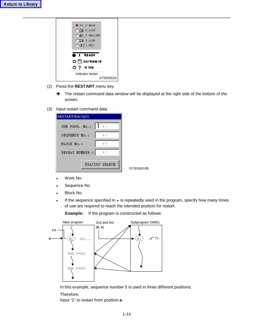
1-14
Indicator lampsD735S0016
(2) Press the RESTART menu key.
Î The restart command data window will be displayed at the right side of the bottom of thescreen.
(3) Input restart command data.
‡ @
‡ C
‡ B
‡ A
D735S0019E
• Work No.
• Sequence No.
• Block No.
• If the sequence specified in • is repeatedly used in the program, specify how many timesof use are required to reach the intended position for restart.
Example: If the program is constructed as follows:
N5 G01...
M98 P9001
M98 P9001
a
1st
Main program
N5 M �a�a
Subprogram O90012nd and 3rd(b, c)
In this example, sequence number 5 is used in three different positions.
Therefore:Input “1” to restart from position a.
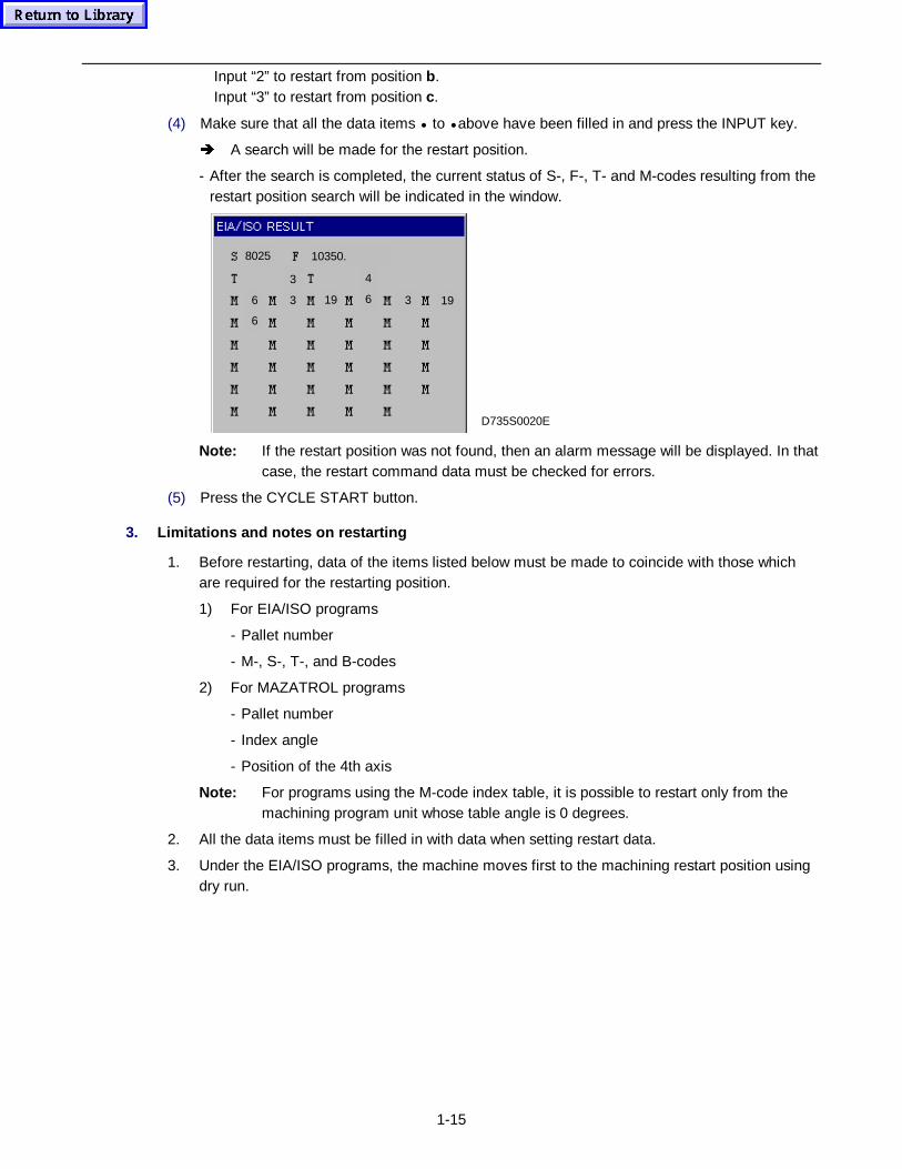
1-15
Input “2” to restart from position b.Input “3” to restart from position c.
(4) Make sure that all the data items • to • above have been filled in and press the INPUT key.
Î A search will be made for the restart position.
- After the search is completed, the current status of S-, F-, T- and M-codes resulting from therestart position search will be indicated in the window.
D735S0020E
1936
6
3
3
4
6
8025 10350.
19
Note: If the restart position was not found, then an alarm message will be displayed. In thatcase, the restart command data must be checked for errors.
(5) Press the CYCLE START button.
3. Limitations and notes on restarting
1. Before restarting, data of the items listed below must be made to coincide with those whichare required for the restarting position.
1) For EIA/ISO programs
- Pallet number
- M-, S-, T-, and B-codes
2) For MAZATROL programs
- Pallet number
- Index angle
- Position of the 4th axis
Note: For programs using the M-code index table, it is possible to restart only from themachining program unit whose table angle is 0 degrees.
2. All the data items must be filled in with data when setting restart data.
3. Under the EIA/ISO programs, the machine moves first to the machining restart position usingdry run.
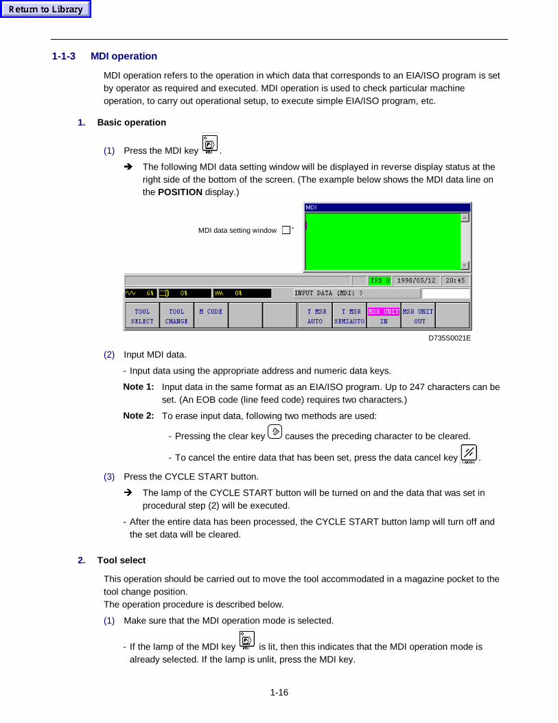
1-16
1-1-3 MDI operation
MDI operation refers to the operation in which data that corresponds to an EIA/ISO program is setby operator as required and executed. MDI operation is used to check particular machineoperation, to carry out operational setup, to execute simple EIA/ISO program, etc.
1. Basic operation
(1) Press the MDI key .
Î The following MDI data setting window will be displayed in reverse display status at theright side of the bottom of the screen. (The example below shows the MDI data line onthe POSITION display.)
MDI data setting window ��
D735S0021E
(2) Input MDI data.
- Input data using the appropriate address and numeric data keys.
Note 1: Input data in the same format as an EIA/ISO program. Up to 247 characters can beset. (An EOB code (line feed code) requires two characters.)
Note 2: To erase input data, following two methods are used:
- Pressing the clear key causes the preceding character to be cleared.
- To cancel the entire data that has been set, press the data cancel key .
(3) Press the CYCLE START button.
Î The lamp of the CYCLE START button will be turned on and the data that was set inprocedural step (2) will be executed.
- After the entire data has been processed, the CYCLE START button lamp will turn off andthe set data will be cleared.
2. Tool select
This operation should be carried out to move the tool accommodated in a magazine pocket to thetool change position.The operation procedure is described below.
(1) Make sure that the MDI operation mode is selected.
- If the lamp of the MDI key is lit, then this indicates that the MDI operation mode isalready selected. If the lamp is unlit, press the MDI key.
1-17
(2) Press the TOOL SELECT menu key.
Î This will cause the display of TOOL SELECT to reverse and the message POCKETNUMBER? to be displayed.
(3) Using the appropriate numeric key(s), specify the identification number of the pocket thataccommodates the tool to be moved to the tool change position. Then, press the INPUT key.
Î “T••• M149 ” will then be displayed in the MDI data setting window and the reverse-display state of TOOL SELECT will be released. (••• above denotes the input pocketnumber.)
(4) Select the conditions for executing the TOOL SELECT operation.
- See the description of procedural step (3) of the item A in Section 1-2-1 “Automaticoperation”.
(5) Press the CYCLE START button.
Î This will cause the start button lamp to light up and the tool that was specified inprocedural step (3) above to start moving to the tool change position.
3. Tool change
This operation should be carried out to mount a tool from the magazine onto the spindle.
If this operation is carried out with another tool being mounted on the spindle, then this tool will beautomatically returned to the required pocket and then the specified tool will be mounted on thespindle.
The procedure for tool change operation is described below.
(1) Make sure that the MDI operation mode is selected.
- If the lamp of the MDI key is lit, then this indicates that the MDI operation mode isalready selected. If the lamp is unlit, press the MDI key.
(2) Press the TOOL CHANGE menu key.
Î This will cause the display of TOOL CHANGE to reverse and the message POCKETNUMBER? to be displayed.
(3) Using the appropriate numeric key(s), specify the identification number of the pocket that
accommodates the tool to be mounted on the spindle. Then, press the INPUT key .
Î “Txxx T0 M6 ” will then be displayed in the MDI data setting window and the reverse-display state of TOOL CHANGE will be released. (xxx denotes the specified pocketnumber, and “T0” denotes the identification number of the next tool specified. In the MDIoperation mode, the next tool command is generally displayed as “T0”.)
Example: To mount on the spindle the tool accommodated in pocket number 12:
Press keys 1 , 2 , and , in that order.
Î This will cause “T012 T0 M6 ” to be displayed in the MDI data setting window.
(4) Select the conditions for executing the TOOL CHANGE operation.
- See the description of procedural step (3) of the item A in Section 1-2-1 “Automaticoperation”.
1-18
(5) Press the CYCLE START button.
Î This will cause the start button lamp to light up and the tool that was specified inprocedural step (3) above to be mounted on the spindle.
- When the tool has been mounted on the spindle, the start button lamp will go out.
4. Setting the M-code
Two methods are available for setting the M-code in the MDI data setting window. One is by usingthe menu keys, and the other, by specifying the M-code using the appropriate numeric keys. Theprocedure for setting the M-code is described below.
(1) Make sure that the MDI operation mode is selected.
- If the lamp of the MDI key is lit, then this indicates that the MDI operation mode isalready selected. If the lamp is unlit, press the MDI key.
(2) Press the M CODE menu key.
Î This will cause the message M CODE (MDI)? to be displayed and the following “M-code(auxiliary-function code) menus” to appear in the menu display area:
01 OPT
STOP.
03 SPNDL
FWD
04 SPNDL
REV
05 SPNDL
STOP
07 MIST
STOP
08 FLOOD
COOLANT
09 OFF
COOLANT
50 AIR
BLAST
>>>(a)
- Each time the >>> menu key is pressed, the menu changes over as follows:
00 PROG
STOP
19 SPNDL
ORIENT
35 T-BRK
DETECT
38 SPNDL
GEAR L/M
39 SPNDL
GEAR H
33 OUT
MSR UNIT
34 IN
MSR UNIT
>>>(b)
16 OPEN
ATC CVR
15 CLOSE
ATC CVR
11 TOOL
UNCLAMP
10 TOOL
CLAMP
53 CHIP
VAC ON
09 CHIP
VAC OFF
>>>(c)
That is, menu changeover occurs in order of (a)• (b)• (c)• (a)• (b)• ....
(3) Set the M-code.
A. Setting the M-code by using the menu keys
Select the function to be used, and press the menu key appropriate to that function.
Î “M•• ” will then be displayed in the MDI data setting window.
(•• denotes the identification number of the selected M-code.)
Example: If the 19 SPNDL ORIENT menu key is pressed, “M19” will be displayed in
the MDI data setting window.
B. Setting the M-code by using the appropriate numeric keys
Input the identification number of the desired M-code by pressing the appropriate numerickeys and then press the INPUT key.
Î “M••• ” will then be displayed in the MDI data setting window.
(••• denotes the identification number of the selected M-code.)
Example: To set M71 (pallet No. 1 selection):
Press keys 7 , 1 , and .
Î This will cause “M071” to be displayed in the MDI data setting window.
- With this method, up to three digits are available for one M-code.
- For details of the functions, refer to the Programming Manual (MAZATROLProgramming) and the Operating manual of the machine.
Remark: When executing the M-code which has been set as described above, first verify the
1-19
execution conditions and then press the start button. (For further details, see thedescription of procedural step (3) of Section 1-2-1, “Auto mode operation”).
5. Measur ing unit IN/OUT
Except some models, the measuring unit must be moved out of its storage position before the toollength can be measured automatically or semi-automatically. In addition, after measurement hasbeen completed, the measuring unit must be replaced in its storage position. The operatingprocedures for moving the measuring unit in or out (MSR UNIT IN or OUT) are described below.See the following Item 6, “Tool-length measurement”, for details of tool-length measurement.
A. Measur ing unit OUT
(1) Make sure that the MDI operation mode is selected.
- If the lamp of the MDI key is lit, then this indicates that the MDI operation mode isalready selected. If the lamp is unlit, press the MDI key.
(2) Press the 33 OUT MSR UNIT menu key.
Î “M33” will be displayed in the MDI data setting window.
(3) Press the CYCLE START button.
Î This will activate the start button lamp and move the measuring unit out of its storageposition.
- When the measuring unit has reached the measurement position, the start button lamp willgo out and the display of 33 OUT MSR UNIT will be reversed.
B. Measur ing unit IN
(1) Make sure that the MDI operation mode is selected.
- If the lamp of the MDI key is lit, then this indicates that the MDI operation mode isalready selected. If the lamp is unlit, press the MDI key.
(2) Press the 34 IN MSR UNIT menu key.
Î “M34” will be displayed in the MDI data setting window.
(3) Press the CYCLE START button.
- This will activate the start button lamp and move the measuring unit back to its storageposition.
- When the measuring unit has reached the storage position, the start button lamp will go outand the display of 34 IN MSR UNIT will be reversed.
6. Tool-length measurement
Before starting a machining operation, it is necessary to measure the lengths of the tools that havebeen mounted in the tool magazine and then to input the measured data to the TOOL LENGTHitem of the TOOL DATA display.This operation is called “tool-length measurement”, for which are available the following threemethods:
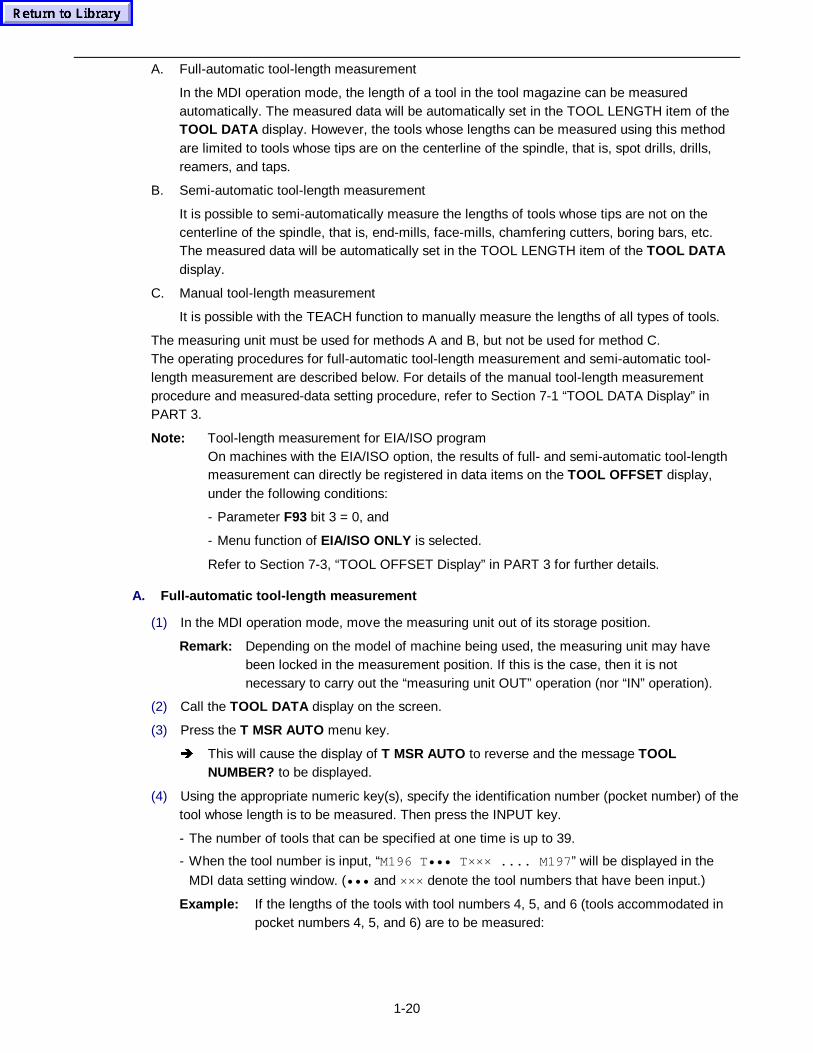
1-20
A. Full-automatic tool-length measurement
In the MDI operation mode, the length of a tool in the tool magazine can be measuredautomatically. The measured data will be automatically set in the TOOL LENGTH item of theTOOL DATA display. However, the tools whose lengths can be measured using this methodare limited to tools whose tips are on the centerline of the spindle, that is, spot drills, drills,reamers, and taps.
B. Semi-automatic tool-length measurement
It is possible to semi-automatically measure the lengths of tools whose tips are not on thecenterline of the spindle, that is, end-mills, face-mills, chamfering cutters, boring bars, etc.The measured data will be automatically set in the TOOL LENGTH item of the TOOL DATAdisplay.
C. Manual tool-length measurement
It is possible with the TEACH function to manually measure the lengths of all types of tools.
The measuring unit must be used for methods A and B, but not be used for method C.The operating procedures for full-automatic tool-length measurement and semi-automatic tool-length measurement are described below. For details of the manual tool-length measurementprocedure and measured-data setting procedure, refer to Section 7-1 “TOOL DATA Display” inPART 3.
Note: Tool-length measurement for EIA/ISO programOn machines with the EIA/ISO option, the results of full- and semi-automatic tool-lengthmeasurement can directly be registered in data items on the TOOL OFFSET display,under the following conditions:
- Parameter F93 bit 3 = 0, and
- Menu function of EIA/ISO ONLY is selected.
Refer to Section 7-3, “TOOL OFFSET Display” in PART 3 for further details.
A. Full-automatic tool-length measurement
(1) In the MDI operation mode, move the measuring unit out of its storage position.
Remark: Depending on the model of machine being used, the measuring unit may havebeen locked in the measurement position. If this is the case, then it is notnecessary to carry out the “measuring unit OUT” operation (nor “IN” operation).
(2) Call the TOOL DATA display on the screen.
(3) Press the T MSR AUTO menu key.
Î This will cause the display of T MSR AUTO to reverse and the message TOOLNUMBER? to be displayed.
(4) Using the appropriate numeric key(s), specify the identification number (pocket number) of thetool whose length is to be measured. Then press the INPUT key.
- The number of tools that can be specified at one time is up to 39.
- When the tool number is input, “M196 T ••• T ××× .... M197 ” will be displayed in the
MDI data setting window. (••• and ××× denote the tool numbers that have been input.)
Example: If the lengths of the tools with tool numbers 4, 5, and 6 (tools accommodated inpocket numbers 4, 5, and 6) are to be measured:
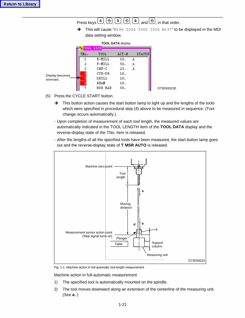
1-21
Press keys 4 , , 5 , , 6 , and , in that order.
Î This will cause “M196 T004 T005 T006 M197 ” to be displayed in the MDI
data setting window.
Display becomesreversed.
D735S0022E
TOOL DATA display
(5) Press the CYCLE START button.
Î This button action causes the start button lamp to light up and the lengths of the toolswhich were specified in procedural step (4) above to be measured in sequence. (Toolchange occurs automatically.)
- Upon completion of measurement of each tool length, the measured values areautomatically indicated in the TOOL LENGTH item of the TOOL DATA display and thereverse-display state of the TNo. item is released.
- After the lengths of all the specified tools have been measured, the start button lamp goesout and the reverse-display state of T MSR AUTO is released.
D735S0023
Machine zero-point
Supportcolumn
Measuring unit
Plunger
Table
Movingdistance
Toollength
a
bd
cMeasurement sensor action point
(Skip signal turns on)
Fig. 1-1 Machine action in full-automatic tool length measurement
Machine action in full-automatic measurement
1) The specified tool is automatically mounted on the spindle.
2) The tool moves downward along an extension of the centerline of the measuring unit.(See a. )
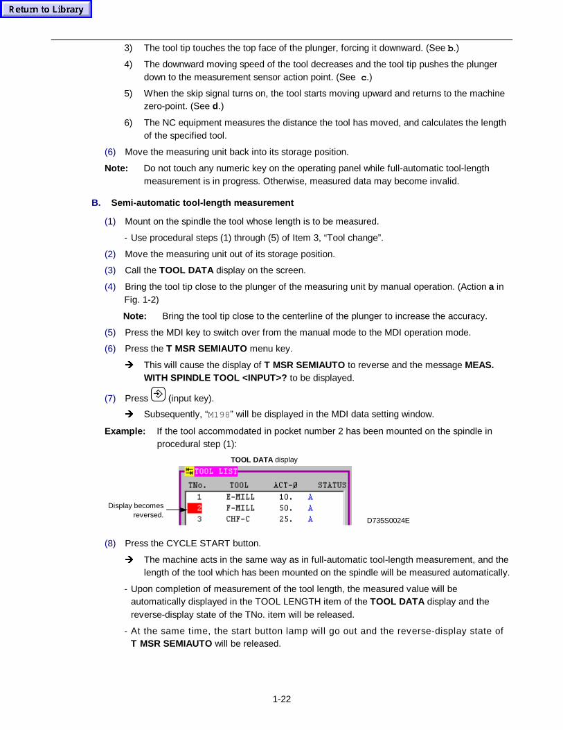
1-22
3) The tool tip touches the top face of the plunger, forcing it downward. (See b.)
4) The downward moving speed of the tool decreases and the tool tip pushes the plungerdown to the measurement sensor action point. (See c .)
5) When the skip signal turns on, the tool starts moving upward and returns to the machinezero-point. (See d.)
6) The NC equipment measures the distance the tool has moved, and calculates the lengthof the specified tool.
(6) Move the measuring unit back into its storage position.
Note: Do not touch any numeric key on the operating panel while full-automatic tool-lengthmeasurement is in progress. Otherwise, measured data may become invalid.
B. Semi-automatic tool-length measurement
(1) Mount on the spindle the tool whose length is to be measured.
- Use procedural steps (1) through (5) of Item 3, “Tool change”.
(2) Move the measuring unit out of its storage position.
(3) Call the TOOL DATA display on the screen.
(4) Bring the tool tip close to the plunger of the measuring unit by manual operation. (Action a inFig. 1-2)
Note: Bring the tool tip close to the centerline of the plunger to increase the accuracy.
(5) Press the MDI key to switch over from the manual mode to the MDI operation mode.
(6) Press the T MSR SEMIAUTO menu key.
Î This will cause the display of T MSR SEMIAUTO to reverse and the message MEAS.WITH SPINDLE TOOL <INPUT>? to be displayed.
(7) Press (input key).
Î Subsequently, “M198” will be displayed in the MDI data setting window.
Example: If the tool accommodated in pocket number 2 has been mounted on the spindle inprocedural step (1):
Display becomesreversed.
D735S0024E
TOOL DATA display
(8) Press the CYCLE START button.
Î The machine acts in the same way as in full-automatic tool-length measurement, and thelength of the tool which has been mounted on the spindle will be measured automatically.
- Upon completion of measurement of the tool length, the measured value will beautomatically displayed in the TOOL LENGTH item of the TOOL DATA display and thereverse-display state of the TNo. item will be released.
- At the same time, the start button lamp will go out and the reverse-display state ofT MSR SEMIAUTO will be released.
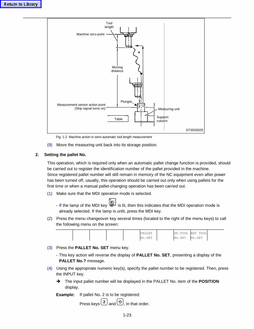
1-23
D735S0025
Machine zero-point
Measurement sensor action point(Skip signal turns on) Measuring unit
SupportcolumnTable
Plunger
a
Toollength
Movingdistance
Fig. 1-2 Machine action in semi-automatic tool length measurement
(9) Move the measuring unit back into its storage position.
2. Setting the pallet No.
This operation, which is required only when an automatic pallet change function is provided, shouldbe carried out to register the identification number of the pallet provided in the machine.Since registered pallet number will still remain in memory of the NC equipment even after powerhas been turned off, usually, this operation should be carried out only when using pallets for thefirst time or when a manual pallet-changing operation has been carried out.
(1) Make sure that the MDI operation mode is selected.
- If the lamp of the MDI key is lit, then this indicates that the MDI operation mode isalready selected. If the lamp is unlit, press the MDI key.
(2) Press the menu changeover key several times (located to the right of the menu keys) to callthe following menu on the screen:
PALLET
No.SET
SP.TOOL
No.SET
NXT TOOL
No.SET
(3) Press the PALLET No. SET menu key.
- This key action will reverse the display of PALLET No. SET , presenting a display of thePALLET No.? message.
(4) Using the appropriate numeric key(s), specify the pallet number to be registered. Then, pressthe INPUT key.
Î The input pallet number will be displayed in the PALLET No. item of the POSITIONdisplay.
Example: If pallet No. 2 is to be registered:
Press keys 2 and , in that order.
1-24
3. Setting the spindle-tool No.
The identification number of the tool currently mounted on the spindle is to be registered by thisoperation. The identification number of the tool currently mounted on the spindle will still remainstored within the memory of the NC equipment even after power has been turned off.
This operation should be carried out only when tools have been manually changed, when the toolhas been manually dismounted from, or mounted onto the spindle.
(1) Make sure that the MDI operation mode is selected.
- If the lamp of the MDI key is lit, then this indicates that the MDI operation mode isalready selected. If the lamp is unlit, press the MDI key.
(2) Press the menu changeover key several times (located to the right of the menu keys) to callthe following menu on the screen:
PALLET
No.SET
SP.TOOL
No.SET
NXT TOOL
No.SET
(3) Press the SP. TOOL No. SET menu key.
Î This key action will reverse the display of SP. TOOL No. SET , presenting a display of theTOOL NUMBER? message.
(4) Using the appropriate numeric key(s), specify the identification number of the tool currentlymounted on the spindle. Then, press the INPUT key.
Î The input tool number and tool name will be displayed in the (left) TNo. item of thePOSITION display.
- Subsequently, the reverse-display state of SP. TOOL No. SET will be released.
Example: If the tool with tool number 5 has been manually mounted on the spindle:
Press keys 5 and , in that order.
Remark: If the tool has been manually dismounted from the spindle and no tool is currentlymounted on it, the tool number 0 should be input.
Note: The magazine pocket corresponding to the tool number which was input in proceduralstep (4) must be left empty.If an ATC operation was aborted by pressing the RESET key or the emergency stopbutton, the tool number of the tool currently mounted on the spindle may have beenerased from the memory. In such a case, therefore, check the tool number beingdisplayed in the TNo. item of the POSITION display for actuality.
4. Setting the next-tool No.
The identification number of the tool currently in the standby state is to be registered by thisoperation.The identification number of the tool currently in the standby state will still remain stored within thememory of the NC equipment even after power has been turned off. This operation should becarried out in case such as those where tools have been manually changed.
The operation procedure is basically the same as that for the item 8 “Setting the spindle-tool No.”.For this operation, press the NXT TOOL No. SET menu key instead of the SP. TOOL No. SETmenu key.
1-25
5. Group-number specification for tool manag ement
A. Tool change with group-number specification
In a tool-management system which applies group numbers for T-code specification in EIA/ISOprogramming, the MDI tool-change operation using the TOOL CHANGE menu function can also bemanaged by specifying 8-digit group numbers.
(1) Make sure that the MDI operation mode is selected.
- If the lamp of the MDI key is lit, then this indicates that the MDI operation mode isalready selected. If the lamp is unlit, press the MDI key.
(2) Press the TOOL CHANGE menu key.
Î This will cause the display of TOOL CHANGE to reverse and the message SAME TOOLGROUP No.? to be displayed.
(3) Using the appropriate numeric key(s), specify the group number of the tool to be mounted onthe spindle. Then, press the INPUT key.
- “Txxxxxxxx T0 M6 ” will then be displayed in the MDI input window and the reverse-displaystate of TOOL CHANGE will be released. (xxxxxxxx denotes the input group number, and“T0” denotes the identification number of the next tool specified.)
For the following operation steps (4) and (5), perform the same operation as described in the item3 “Tool change”.
B. Next-tool co mmand with group-number specification
The next-tool command can be executed by specifying a group number in the free-format for theMDI operation mode.
Example: If a tool registered under group number 12 is to be mounted on the spindle and a toolof group number 13 is to be indexed as the next tool:Enter “T00000012 T00000013 M6 ” on the MDI data setting window.
C. Tool select with group-number specification
In a tool-management system which applies group numbers for T-code specification in EIA/ISOprogramming, the MDI tool-select operation using the TOOL SELECT menu function can also bemanaged by specifying 8-digit group numbers.
(1) Make sure that the MDI operation mode is selected.
- If the lamp of the MDI key is lit, then this indicates that the MDI operation mode isalready selected. If the lamp is unlit, press the MDI key.
(2) Press the TOOL SELECT menu key.
Î This will cause the display of TOOL SELECT to reverse and the message SAME TOOLGROUP No.? to be displayed.
(3) Using the appropriate numeric key(s), specify the group number of the tool to be moved to thetool change position. Then, press the INPUT key.
- “T•••••••• M149” will then be displayed in the MDI data setting window and the reverse-display state of TOOL SELECT will be released. (•••••••• above denotes the input groupnumber.)
For the following operation steps (4) and (5), perform the same operation as described in the item2 “Tool select”.

1-26
D. Parameters related to T OOL CHANGE and TOOL SELECT
L51 0: Pocket-number specification1: Group-number specification
F94 bit 4 0: Group number(Tool searching) 1: Tool (pocket) number
If the EIA/ISO option is not provided, only pocket-number specification is valid, irrespective of thevalue of parameter L51.
Note: If the value “0” (group number specification) is set in parameter F94 bit 4, group-numberspecification is valid even during automatic operation.
Remark: Register group numbers by setting them in the data item GROUP No. of the TOOLDATA display.
2-1
2 SELECTING EXECUTION CONDITIONS
The following functions are available with the execution conditions selection menu or key forautomatic operation:
1) Optional Stop2) Dry Run3) Machine Lock4) Work Light5) Block Skip (for EIA/ISO programs only)6) Single Block7) Comparison Stop8) Z-axis Cancel9) MST Lock
10) ATC Stop11) TUNING SV PARAM
These functions can be selected for all automatic operation modes (memory mode, tape operationmode, and MDI mode).
During automatic operation, these functions can also be selected or canceled.
Functions 3) and 4) listed above can also be selected during the manual operation mode.
Function 11) above cannot be selected in the MDI mode.
The execution conditions selection menu for automatic operation can be displayed while any oneof the following displays stays on the CRT screen:
- POSITION display
- TRACE display
- EIA MONITOR display
- PALLET MANG. display
Note: If the execution conditions selection menu is not displayed when one of these displayshas been selected, then press the menu changeover key.
A description of each function and its usage follows.
2-1 Optional Stop
Optional Stop refers to the function with which the automatic operation can be optionally stopped atthe end of a block containing M01 code.
Select this function when you want to decide step by step whether to continue or to discontinue theautomatic operation.
2-1-1 Procedure
Set M01 (optional stop) in the position where automatic operation is to be halted.
- For MAZATROL programs, the M-code can be set in the following positions:M-code unit: Data item “M1” through “M8”Machining unit: Sequence data item “M”
- For EIA/ISO programs, the M-code can be set in any block.
(1) Press the OPTIONAL STOP menu key.
è OPTIONAL STOP will change into a reverse display status to indicate that the OptionalStop function has become active.
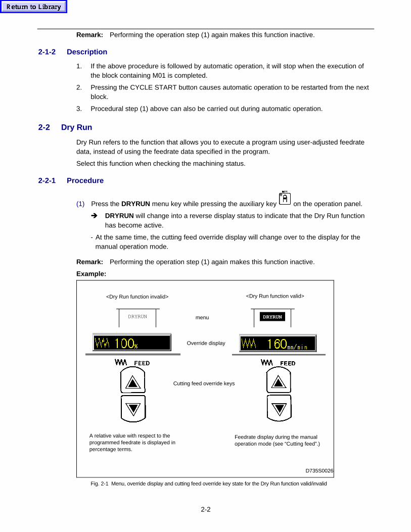
2-2
Remark: Performing the operation step (1) again makes this function inactive.
2-1-2 Description
1. If the above procedure is followed by automatic operation, it will stop when the execution ofthe block containing M01 is completed.
2. Pressing the CYCLE START button causes automatic operation to be restarted from the nextblock.
3. Procedural step (1) above can also be carried out during automatic operation.
2-2 Dry Run
Dry Run refers to the function that allows you to execute a program using user-adjusted feedratedata, instead of using the feedrate data specified in the program.
Select this function when checking the machining status.
2-2-1 Procedure
(1) Press the DRYRUN menu key while pressing the auxiliary key on the operation panel.
è DRYRUN will change into a reverse display status to indicate that the Dry Run functionhas become active.
- At the same time, the cutting feed override display will change over to the display for themanual operation mode.
Remark: Performing the operation step (1) again makes this function inactive.
Example:
D735S0026
DRYRUN menu
<Dry Run function valid><Dry Run function invalid>
DRYRUN
Cutting feed override keys
Override display
A relative value with respect to theprogrammed feedrate is displayed inpercentage terms.
Feedrate display during the manualoperation mode (see “Cutting feed”.)
Fig. 2-1 Menu, override display and cutting feed override key state for the Dry Run function valid/invalid
2-3
(2) Adjust the feedrate using the cutting feed override keys.
2-2-2 Description
- When the above procedure is followed by automatic operation, the program will be executedusing the adjusted feedrate data.
- Carrying out procedural step (1) above during automatic operation nullifies the programmedfeedrate and the manual cutting feedrate will be selected.
2-3 Machine Lock
Machine Lock refers to the function that runs the program with no axis movement.
Selecting this function makes the current-position counter indicate the programmed axismovements, even though they do not actually take place.
Use this function when the program execution status is to be checked.
2-3-1 Procedure
(1) Press the MACHINE LOCK menu key while pressing and holding down the auxiliary key
on the operation panel.
è MACHINE LOCK will then change into a reverse display status to indicate that theMachine Lock function has become active.
Remark: Performing the operation step (1) again makes this function inactive.
2-3-2 Description
1. When the above procedure is followed by automatic operation, the program will be executedwithout actual movements of all axes excepting the spindle.
2. Selecting the Machine Lock function during automatic operation brings automatic operation tosingle-block stop at the end of the block being executed. If automatic operation issubsequently restarted, then the succeeding portion of that program will be executed with themachine remaining locked.Do not cancel the Machine Lock function while the machine is in automatic operation.If the Machine Lock function is canceled during automatic operation with the machineremaining locked, actual movements of the axes will begin at the end of the block beingexecuted.
However, under a machine locked status, the machine position that the NC unit stores in itsmemory will more or less differ from the actual machine position. After the Machine Lockfunction has been canceled, therefore, a collision of the machine can arise since the axismovement will be carried out in such a disturbed coordinates system.
2-4 Work Light
Work Light refers to the function that turns on or off the illumination lamps mounted on themachine.
2-4-1 Procedure
(1) Press the WORK LIGHT menu key.
è WORK LIGHT will change into a reverse display status, turning the lamps on.
2-4
Remark: Performing the operation step (1) again makes this function inactive.
2-5 Block Skip
Block Skip refers to the function with which the specific blocks can be optionally skipped duringprogram execution.
This function is only valid for EIA/ISO programs.
2-5-1 Procedure
Include a slash in the starting part of the block(s) to be optionally skipped.
Example: /G �
(1) Press the BLOCK SKIP menu key.
è BLOCK SKIP will then change into a reverse display status to indicate that the BlockSkip function has become active.
Remark: Performing the operation step (1) again makes this function inactive.
2-5-2 Description
1. When the above procedure is followed by automatic operation, the program will run skippingthrough the designated block(s).
2. Slash can be set only at the head of the block or after the sequence number.For further details see the Programming Manual (EIA/ISO Programming).
2-6 Single Block
Single Block refers to the function used to execute a program on a block-by-block basis.
Select this function to check the machine actions and the machining status.
2-6-1 Procedure
(1) Press the
SINGLEBLOCK
key.
è The key lamp will turn on to indicate that the Single Block function has become active.
Remark: Performing the operation step (1) again makes this function inactive.
2-6-2 Description
1. When the above procedure is followed by automatic operation, the CYCLE START buttonlamp will go out when the first block of the program is executed. At the same time, automaticoperation will stop.When automatic operation is restarted by pressing the CYCLE START button once again, thenext block will be executed and automatic operation will stop once again.
In this manner, once Single Block has been selected, automatic operation restarts each timethe CYCLE START button is pressed, and stops each time one block is executed.
2. When the above procedure is performed during automatic operation, it will stop at the end ofthe block being executed. The Single Block function will become active when automaticoperation is restarted by pressing the CYCLE START button.The stop of automatic operation at the end of the block being executed is referred to as single-block stop.
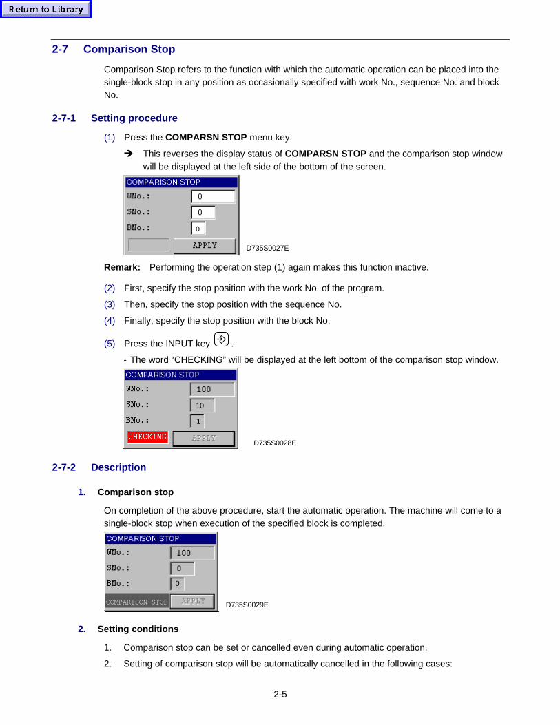
2-5
2-7 Comparison Stop
Comparison Stop refers to the function with which the automatic operation can be placed into thesingle-block stop in any position as occasionally specified with work No., sequence No. and blockNo.
2-7-1 Setting procedure
(1) Press the COMPARSN STOP menu key.
è This reverses the display status of COMPARSN STOP and the comparison stop windowwill be displayed at the left side of the bottom of the screen.
D735S0027E
0
Remark: Performing the operation step (1) again makes this function inactive.
(2) First, specify the stop position with the work No. of the program.
(3) Then, specify the stop position with the sequence No.
(4) Finally, specify the stop position with the block No.
(5) Press the INPUT key .
- The word “CHECKING” will be displayed at the left bottom of the comparison stop window.
1
10
D735S0028E
2-7-2 Description
1. Comparison stop
On completion of the above procedure, start the automatic operation. The machine will come to asingle-block stop when execution of the specified block is completed.
D735S0029ECOMPARISON STOP
0
2. Setting conditions
1. Comparison stop can be set or cancelled even during automatic operation.
2. Setting of comparison stop will be automatically cancelled in the following cases:
2-6
- The machine operation has come to the comparison stop correctly as specified.
- The system has entered the reset status (at the end of a cycle or by pressing the RESETkey).
3. Comparison stop is only available in MEMORY, TAPE , HARD DISK or IC memory cardoperation mode.
3. Detailed description
1. If the program has multiple blocks which correspond with the specified sequence No. andblock No., comparison stop will occur at the first of such blocks.
2. Comparison stop function does not include checking for the presence of the specified block inthe respective program.
3. The sequential operation of tapping cannot be brought half-way to a comparison stop.
4. The setting of comparison stop is not valid for a block which is currently executed.
5. Only the setting of 0 for the block No. can be omitted.
6. The head block containing a program No. cannot be effective for comparison stop. In otherwords, the setting of 0 for both sequence and block Nos. is ineffective.
7. Setting the work No. of a MAZATROL program will cause an alarm (439 MAZATROLPROGRAM DESIGNATED).
8. Comparison stop for a subprogram which is called multiple times will occur on the first call.
9. The sequential operation of high-speed machining cannot be brought half-way to acomparison stop.
10. If a block for fixed-cycle call is specified, comparison stop will occur on completion of the firstblock of fixed-cycle macroprogram.
11. Whichever block in a series of macro statements is specified, comparison stop will alwaysoccur at the first block.
Example: In case of NNo. = 1 and BNo. = 2:
G28 X0 Y0 Z0
G01 X50.
N01 #100 = 1..........................Actual stop position#101 = 2.
#102 = 3..........................Specified positionN02 M02
The designation of any block of the above-mentioned type, however, can be validated forcomparison stop by setting parameter F93 bit 6 (User-macro-statement processing for single-block operation) to “1”.
12. Even if the block succeeding a block to be skipped is specified, comparison stop will occur atthe skipped block.
Example: In case of NNo. = 1 and BNo. = 2 (with BLOCK SKIP 1 selection)
G28 X0 Y0 Z0
N01 G91 G01 X10. F1000
/1 X10. .........................Actual stop positionY10. .........................Specified positionZ10.
N02 M02
2-7
The designation of such a block as mentioned above, however, can be validated forcomparison stop by setting parameter F93 bit 6 to “1”.
13. Even if the succeeding block of M98 in the calling program is specified during comparisonstop after the M99 block of the called program, the restarted operation will not come to acomparison stop at the required position.
Example:
WNo. 100 (Main program) WNo. 200 (Subprogram)G28 X0Y0Z0 N01 X10.
G91 G01 X10. F1000 X10.
M98 P200 X10.
M98 P200.....Specified position X10.
M02 M99 ............ Specification during
comparison stop here
2-8 Z-axis Cancel
Z-axis Cancel is a function that allows automatic operation to be performed with the Z-axisremaining locked in place. This function should be selected when checking the movements of theX-axis and Y-axis. Even when this function is selected, all machine actions (including the Z-axismovement) will also be displayed on the screen.
2-8-1 Procedure
(1) Press the Z AXIS CANCEL menu key while pressing the auxiliary key .
è The display of Z AXIS CANCEL will reverse.
Remark: Performing the operation step (1) again makes this function inactive.
2-8-2 Description
1. When the automatic operation is started on completion of the above procedure, the specifiedprogram will be executed with the Z-axis remaining locked in place.
2. If procedural step (1) is carried out during automatic operation, it will stop after completion ofthe block being executed (single-block stop), and then the start button lamp will go out. If thestart button is subsequently pressed again, automatic operation will restart, at which time theZ-axis Cancel function will be operative.
Note: After the Z-AXIS CANCEL function has been cleared, the actual position of the Z-axismay differ from the programmed position of the Z-axis.
2-9 MST Lock
MST Lock is a function that allows the M-, S-, T- and B-codes to be disregarded during automaticoperation. When checking the contents of a program, this function should be selected.
The following codes, however, will be implemented even when this function is selected:
- M00 (Program stop)- M01 (Optional stop)- M02 (Program end)- M30 (Reset and rewind)- M98 (Subprogram call)- M99 (Subprogram end)
2-8
2-9-1 Procedure
(1) Press the MST LOCK menu key while pressing the auxiliary key .
è The display of MST LOCK will reverse.
Remark: Performing the operation step (1) again makes this function inactive.
2-9-2 Description
1. When the CYCLE START button is pressed on completion of the above procedure, thespecified program will be executed with the axis movement and M-, S-, T- and B-codefunctions remaining locked.
2. All the programmed machine actions will be displayed on the screen.
3. If procedural steps (1) is carried out during automatic operation, it will stop after the end of theblock being executed (single-block stop), and then the start button lamp will go out.If the start button is subsequently pressed again, automatic operation will restart, at which timethe MST LOCK function will be operative.
Note: After the MACHINE LOCK function has been cleared, the actual operational status of themachine may differ from the corresponding contents of the program.
Remark: If MST LOCK function is selected together with the MACHINE LOCK function, theprogram is run only inside the NC unit and no action of the machine will be carried out.Use these functions together when the program is to be checked in the first stage.
2-10 ATC Stop
If the ATC (automatic tool change) STOP menu function is selected during automatic operation,the machine action will stop at the ATC position after the machining with the tool currently usedhas been completed.
If the ATC STOP menu function is selected during ATC, then the ATC operation will be completedand the machine action will stop immediately before the next ATC operation. Automatic operationcan be restarted by pressing the CYCLE START button after cancellation of the ATC STOP menufunction.
Operating actions associated with ATC operation slightly differ according to the machine models.For details, refer to the Operating Manual for your machine.
2-11 TUNING SV PARAM
TUNING SV PARAM is a function that lets the NC unit automatically estimate the characteristics ofthe machine and the motor after automatic operation, then optimize these characteristics accordingto actual machining conditions so that tool path errors do not occur, and set the optimumcharacteristic data in the required parameter automatically. Thus, the corresponding axes aredriven accurately.
Select this function in the following cases:
1. When mounting a large-mass workpiece and machining it at high accuracy
2. When calculating the optimum data at any specific position of the machine
3. When highly accurate machining is required
To use this function, the Shape Correction Option and the MAZAK Precision Rapid Boring TornadoOption are required. Alarm 936: OPTION NOT FOUND (4, 0, 0) will occur if this function isselected for a machine not provided with the above two options.
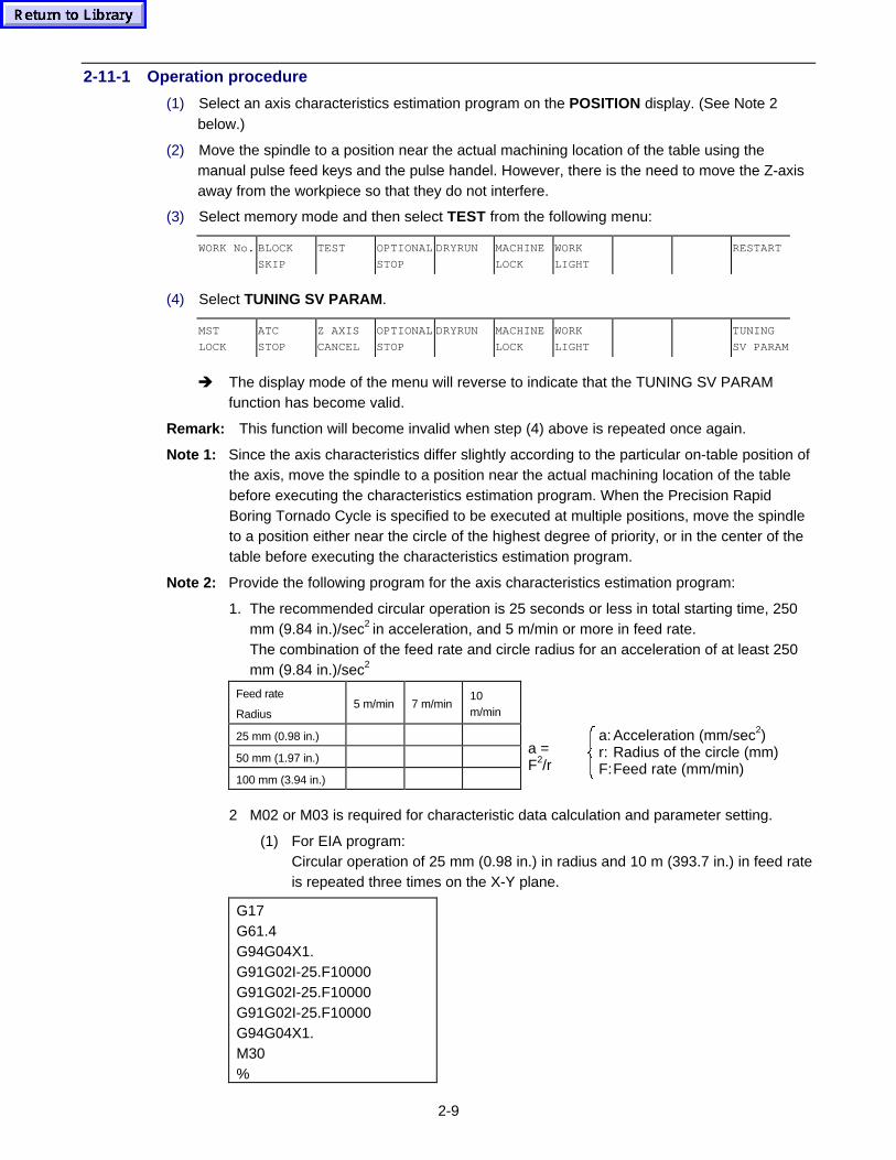
2-9
2-11-1 Operation procedure
(1) Select an axis characteristics estimation program on the POSITION display. (See Note 2below.)
(2) Move the spindle to a position near the actual machining location of the table using themanual pulse feed keys and the pulse handel. However, there is the need to move the Z-axisaway from the workpiece so that they do not interfere.
(3) Select memory mode and then select TEST from the following menu:
WORK No. BLOCK
SKIP
TEST OPTIONAL
STOP
DRYRUN MACHINE
LOCK
WORK
LIGHT
RESTART
(4) Select TUNING SV PARAM.
MST
LOCK
ATC
STOP
Z AXIS
CANCEL
OPTIONAL
STOP
DRYRUN MACHINE
LOCK
WORK
LIGHT
TUNING
SV PARAM
è The display mode of the menu will reverse to indicate that the TUNING SV PARAMfunction has become valid.
Remark: This function will become invalid when step (4) above is repeated once again.
Note 1: Since the axis characteristics differ slightly according to the particular on-table position ofthe axis, move the spindle to a position near the actual machining location of the tablebefore executing the characteristics estimation program. When the Precision RapidBoring Tornado Cycle is specified to be executed at multiple positions, move the spindleto a position either near the circle of the highest degree of priority, or in the center of thetable before executing the characteristics estimation program.
Note 2: Provide the following program for the axis characteristics estimation program:
1. The recommended circular operation is 25 seconds or less in total starting time, 250mm (9.84 in.)/sec2 in acceleration, and 5 m/min or more in feed rate.The combination of the feed rate and circle radius for an acceleration of at least 250mm (9.84 in.)/sec2
Feed rate
Radius5 m/min 7 m/min
10m/min
25 mm (0.98 in.) � � �
50 mm (1.97 in.) � �
100 mm (3.94 in.) �
a =F2/r
a: Acceleration (mm/sec2)r: Radius of the circle (mm)F:Feed rate (mm/min)
2 M02 or M03 is required for characteristic data calculation and parameter setting.
(1) For EIA program:Circular operation of 25 mm (0.98 in.) in radius and 10 m (393.7 in.) in feed rateis repeated three times on the X-Y plane.
G17G61.4G94G04X1.G91G02I-25.F10000G91G02I-25.F10000G91G02I-25.F10000G94G04X1.M30%
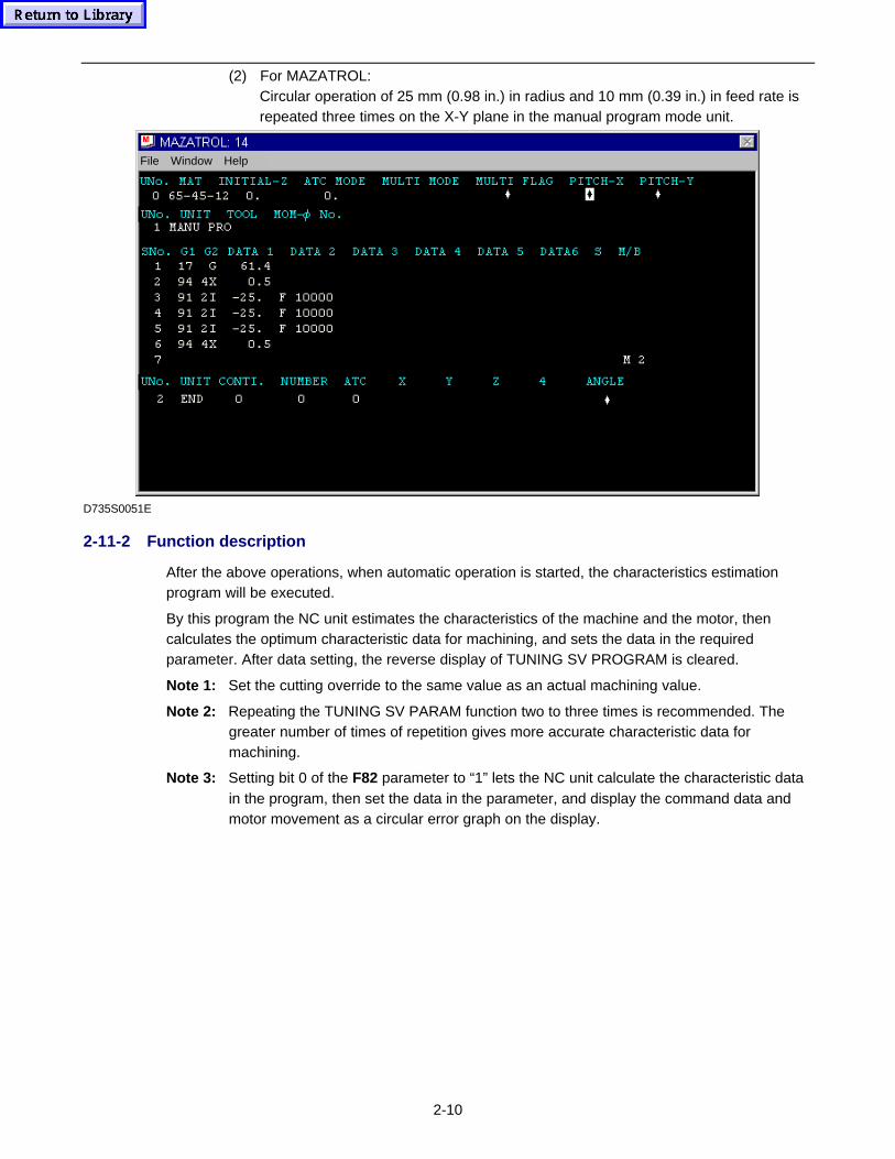
2-10
(2) For MAZATROL:Circular operation of 25 mm (0.98 in.) in radius and 10 mm (0.39 in.) in feed rate isrepeated three times on the X-Y plane in the manual program mode unit.
File Window Help
D735S0051E
2-11-2 Function description
After the above operations, when automatic operation is started, the characteristics estimationprogram will be executed.
By this program the NC unit estimates the characteristics of the machine and the motor, thencalculates the optimum characteristic data for machining, and sets the data in the requiredparameter. After data setting, the reverse display of TUNING SV PROGRAM is cleared.
Note 1: Set the cutting override to the same value as an actual machining value.
Note 2: Repeating the TUNING SV PARAM function two to three times is recommended. Thegreater number of times of repetition gives more accurate characteristic data formachining.
Note 3: Setting bit 0 of the F82 parameter to “1” lets the NC unit calculate the characteristic datain the program, then set the data in the parameter, and display the command data andmotor movement as a circular error graph on the display.
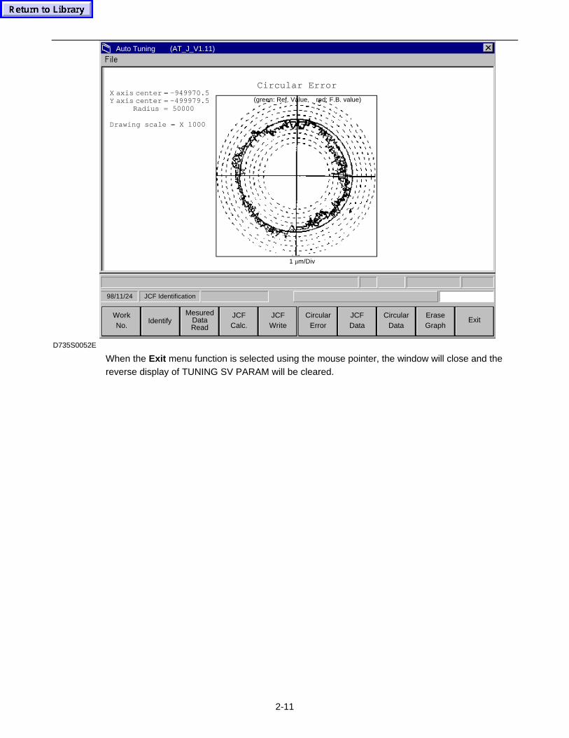
2-11
Auto Tuning (AT_J_V1.11)
ExitEraseGraph
CircularData
JCFData
CircularError
JCFWrite
JCFCalc.
MesuredDataRead
IdentifyWorkNo.
JCF Identification98/11/24
1 µm/Div
(green: Ref. Value, red: F.B. value)
Circular ErrorX axis center = –949970.5Y axis center = –499979.5
Radius = 50000
Drawing scale = X 1000
D735S0052E
When the Exit menu function is selected using the mouse pointer, the window will close and thereverse display of TUNING SV PARAM will be cleared.

2-12
- NOTE -
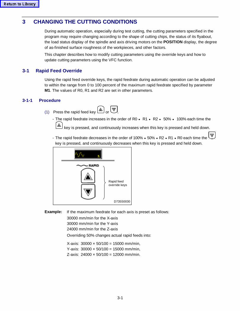
3-1
3 CHANGING THE CUTTING CONDITIONS
During automatic operation, especially during test cutting, the cutting parameters specified in theprogram may require changing according to the shape of cutting chips, the status of its flyabout,the load status display of the spindle and axis driving motors on the POSITION display, the degreeof as-finished surface roughness of the workpieces, and other factors.
This chapter describes how to modify cutting parameters using the override keys and how toupdate cutting parameters using the VFC function.
3-1 Rapid Feed Override
Using the rapid feed override keys, the rapid feedrate during automatic operation can be adjustedto within the range from 0 to 100 percent of the maximum rapid feedrate specified by parameterM1. The values of R0, R1 and R2 are set in other parameters.
3-1-1 Procedure
(1) Press the rapid feed key or .
- The rapid feedrate increases in the order of R0 • R1 • R2 • 50% • 100% each time the
key is pressed, and continuously increases when this key is pressed and held down.
- The rapid feedrate decreases in the order of 100% • 50% • R2 • R1 • R0 each time the key is pressed, and continuously decreases when this key is pressed and held down.
D735S0030
Rapid feedoverride keys
Example: If the maximum feedrate for each axis is preset as follows:
30000 mm/min for the X-axis30000 mm/min for the Y-axis24000 mm/min for the Z-axis
Overriding 50% changes actual rapid feeds into:
X-axis: 30000 × 50/100 = 15000 mm/min,Y-axis: 30000 × 50/100 = 15000 mm/min,Z-axis: 24000 × 50/100 = 12000 mm/min.
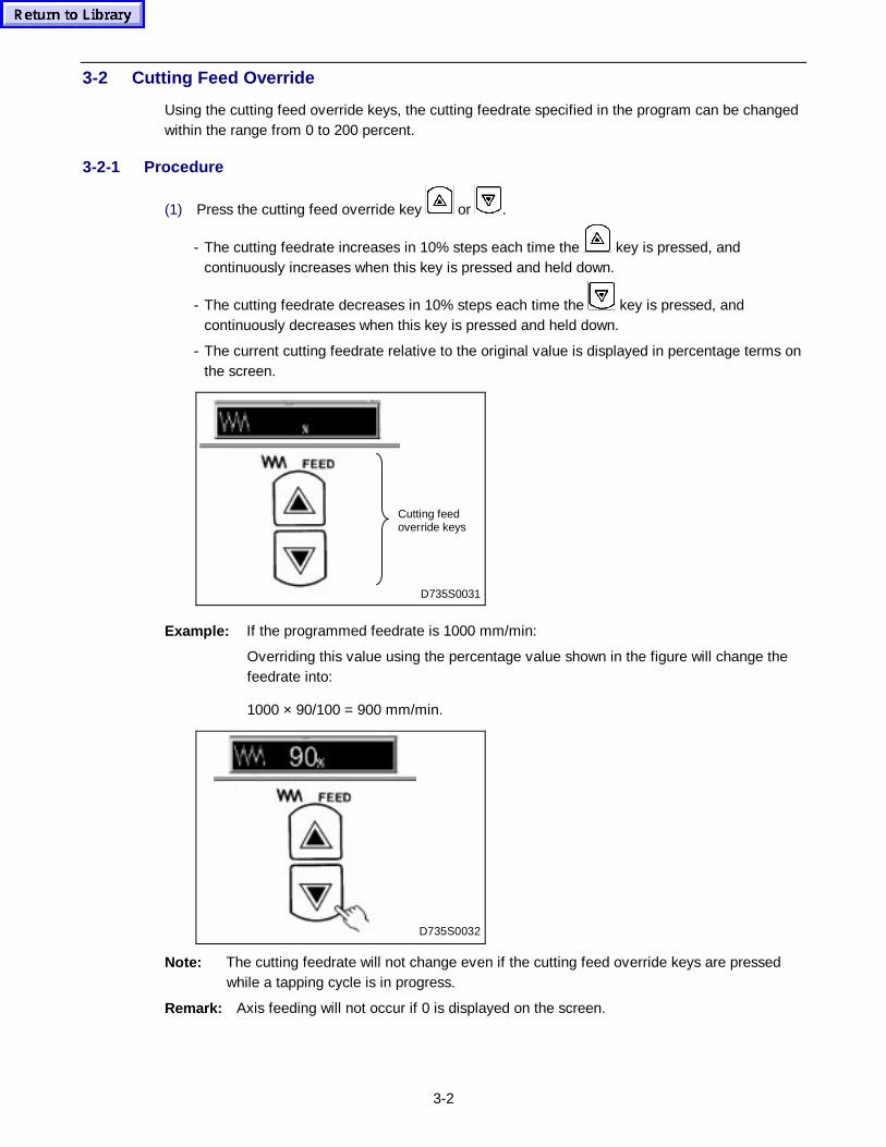
3-2
3-2 Cutting Feed Override
Using the cutting feed override keys, the cutting feedrate specified in the program can be changedwithin the range from 0 to 200 percent.
3-2-1 Procedure
(1) Press the cutting feed override key or .
- The cutting feedrate increases in 10% steps each time the key is pressed, andcontinuously increases when this key is pressed and held down.
- The cutting feedrate decreases in 10% steps each time the key is pressed, andcontinuously decreases when this key is pressed and held down.
- The current cutting feedrate relative to the original value is displayed in percentage terms onthe screen.
D735S0031
Cutting feedoverride keys
Example: If the programmed feedrate is 1000 mm/min:
Overriding this value using the percentage value shown in the figure will change thefeedrate into:
1000 × 90/100 = 900 mm/min.
D735S0032
Note: The cutting feedrate will not change even if the cutting feed override keys are pressedwhile a tapping cycle is in progress.
Remark: Axis feeding will not occur if 0 is displayed on the screen.
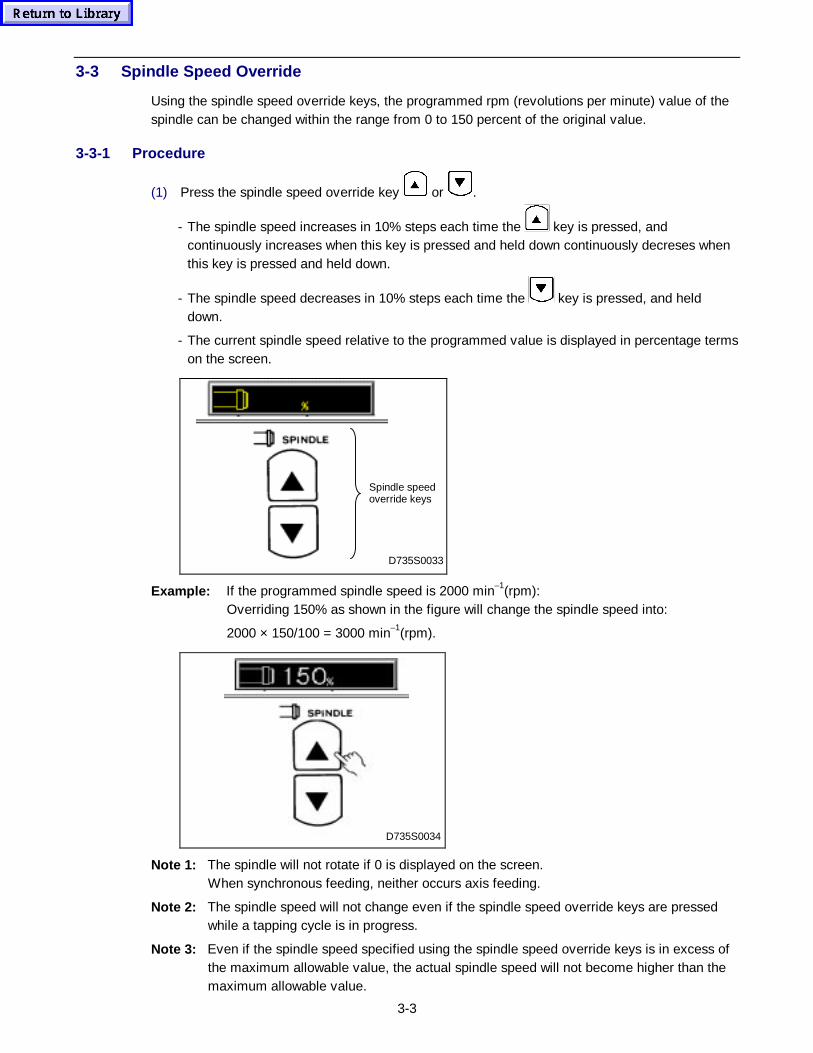
3-3
3-3 Spindle Speed Override
Using the spindle speed override keys, the programmed rpm (revolutions per minute) value of thespindle can be changed within the range from 0 to 150 percent of the original value.
3-3-1 Procedure
(1) Press the spindle speed override key or .
- The spindle speed increases in 10% steps each time the key is pressed, andcontinuously increases when this key is pressed and held down continuously decreses whenthis key is pressed and held down.
- The spindle speed decreases in 10% steps each time the key is pressed, and helddown.
- The current spindle speed relative to the programmed value is displayed in percentage termson the screen.
D735S0033
Spindle speedoverride keys
Example: If the programmed spindle speed is 2000 min–1(rpm):Overriding 150% as shown in the figure will change the spindle speed into:
2000 × 150/100 = 3000 min–1(rpm).
D735S0034
Note 1: The spindle will not rotate if 0 is displayed on the screen.When synchronous feeding, neither occurs axis feeding.
Note 2: The spindle speed will not change even if the spindle speed override keys are pressedwhile a tapping cycle is in progress.
Note 3: Even if the spindle speed specified using the spindle speed override keys is in excess ofthe maximum allowable value, the actual spindle speed will not become higher than themaximum allowable value.
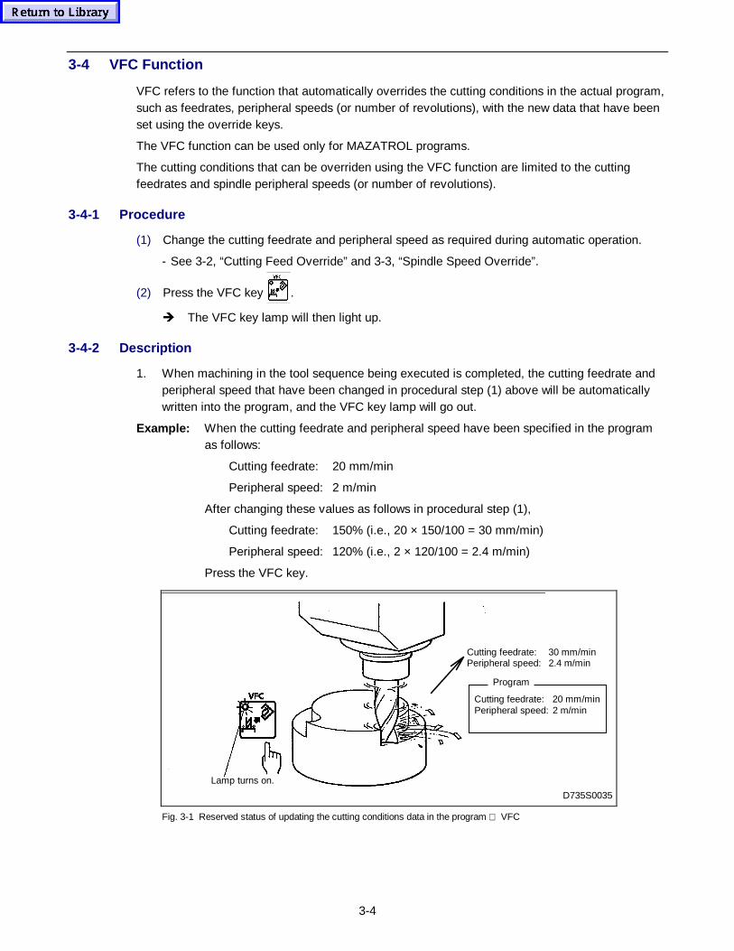
3-4
3-4 VFC Function
VFC refers to the function that automatically overrides the cutting conditions in the actual program,such as feedrates, peripheral speeds (or number of revolutions), with the new data that have beenset using the override keys.
The VFC function can be used only for MAZATROL programs.
The cutting conditions that can be overriden using the VFC function are limited to the cuttingfeedrates and spindle peripheral speeds (or number of revolutions).
3-4-1 Procedure
(1) Change the cutting feedrate and peripheral speed as required during automatic operation.
- See 3-2, “Cutting Feed Override” and 3-3, “Spindle Speed Override”.
(2) Press the VFC key .
Î The VFC key lamp will then light up.
3-4-2 Description
1. When machining in the tool sequence being executed is completed, the cutting feedrate andperipheral speed that have been changed in procedural step (1) above will be automaticallywritten into the program, and the VFC key lamp will go out.
Example: When the cutting feedrate and peripheral speed have been specified in the programas follows:
Cutting feedrate: 20 mm/min
Peripheral speed: 2 m/min
After changing these values as follows in procedural step (1),
Cutting feedrate: 150% (i.e., 20 × 150/100 = 30 mm/min)
Peripheral speed: 120% (i.e., 2 × 120/100 = 2.4 m/min)
Press the VFC key.
D735S0035
Lamp turns on.
Cutting feedrate: 20 mm/minPeripheral speed: 2 m/min
Program
Cutting feedrate: 30 mm/minPeripheral speed: 2.4 m/min
Fig. 3-1 Reserved status of updating the cutting conditions data in the program VFC
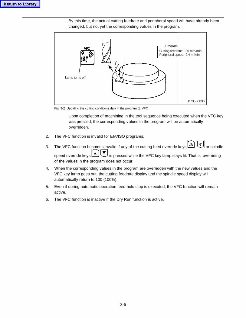
3-5
By this time, the actual cutting feedrate and peripheral speed will have already beenchanged, but not yet the corresponding values in the program.
Lamp turns off.
D735S0036
Cutting feedrate: 30 mm/minPeripheral speed: 2.4 m/min
Program
Fig. 3-2 Updating the cutting conditions data in the program VFC
Upon completion of machining in the tool sequence being executed when the VFC keywas pressed, the corresponding values in the program will be automaticallyoverridden.
2. The VFC function is invalid for EIA/ISO programs.
3. The VFC function becomes invalid if any of the cutting feed override keys
ca
or spindle
speed override keys is pressed while the VFC key lamp stays lit. That is, overridingof the values in the program does not occur.
4. When the corresponding values in the program are overridden with the new values and theVFC key lamp goes out, the cutting feedrate display and the spindle speed display willautomatically return to 100 (100%).
5. Even if during automatic operation feed-hold stop is executed, the VFC function will remainactive.
6. The VFC function is inactive if the Dry Run function is active.
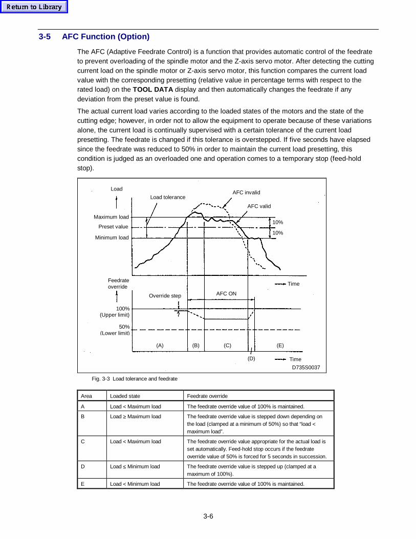
3-6
3-5 AFC Function (Option)
The AFC (Adaptive Feedrate Control) is a function that provides automatic control of the feedrateto prevent overloading of the spindle motor and the Z-axis servo motor. After detecting the cuttingcurrent load on the spindle motor or Z-axis servo motor, this function compares the current loadvalue with the corresponding presetting (relative value in percentage terms with respect to therated load) on the TOOL DATA display and then automatically changes the feedrate if anydeviation from the preset value is found.
The actual current load varies according to the loaded states of the motors and the state of thecutting edge; however, in order not to allow the equipment to operate because of these variationsalone, the current load is continually supervised with a certain tolerance of the current loadpresetting. The feedrate is changed if this tolerance is overstepped. If five seconds have elapsedsince the feedrate was reduced to 50% in order to maintain the current load presetting, thiscondition is judged as an overloaded one and operation comes to a temporary stop (feed-holdstop).
Load
Maximum load
Preset value
Minimum load
Load toleranceAFC invalid
AFC valid
10%
10%
Time
AFC ONOverride step
Feedrateoverride
100%(Upper limit)
50%(Lower limit)
(E)(A) (B) (C)
(D) Time
D735S0037
Fig. 3-3 Load tolerance and feedrate
Area Loaded state Feedrate override
A Load < Maximum load The feedrate override value of 100% is maintained.
B Load ≥ Maximum load The feedrate override value is stepped down depending onthe load (clamped at a minimum of 50%) so that “load <maximum load”.
C Load < Maximum load The feedrate override value appropriate for the actual load isset automatically. Feed-hold stop occurs if the feedrateoverride value of 50% is forced for 5 seconds in succession.
D Load ≤ Minimum load The feedrate override value is stepped up (clamped at amaximum of 100%).
E Load < Minimum load The feedrate override value of 100% is maintained.
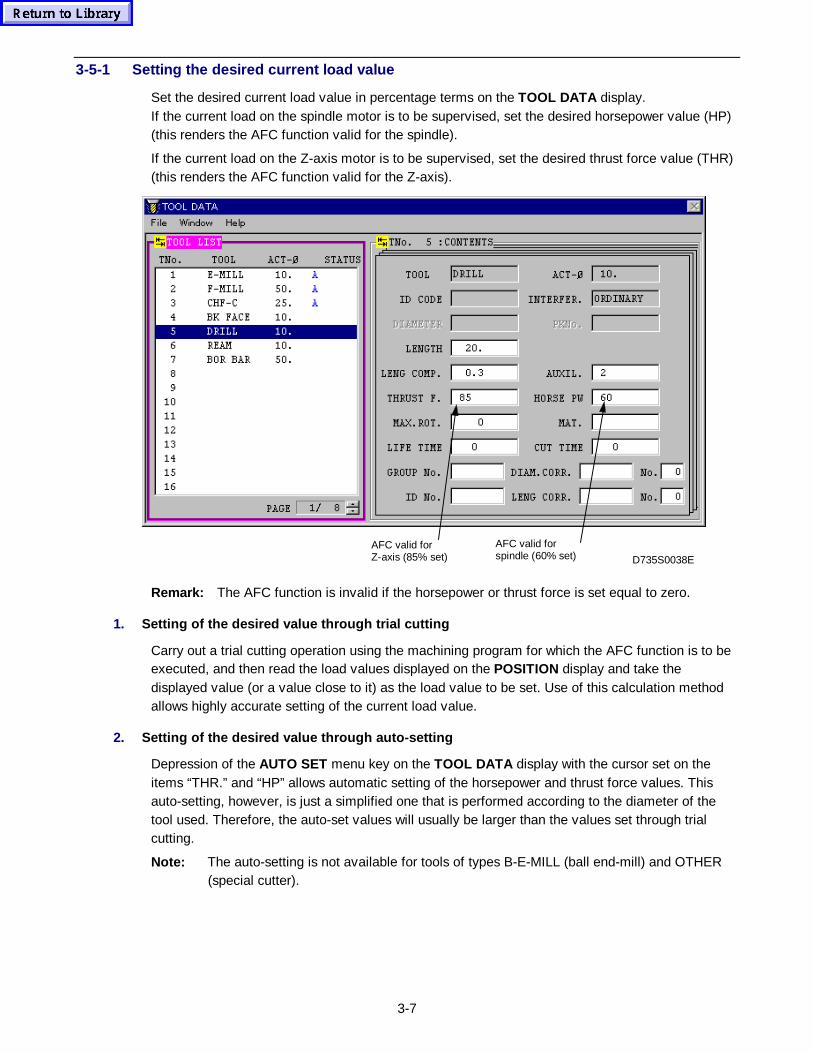
3-7
3-5-1 Setting the desired current load value
Set the desired current load value in percentage terms on the TOOL DATA display.If the current load on the spindle motor is to be supervised, set the desired horsepower value (HP)(this renders the AFC function valid for the spindle).
If the current load on the Z-axis motor is to be supervised, set the desired thrust force value (THR)(this renders the AFC function valid for the Z-axis).
AFC valid forZ-axis (85% set)
AFC valid forspindle (60% set) D735S0038E
Remark: The AFC function is invalid if the horsepower or thrust force is set equal to zero.
1. Setting of the desired value through trial cutting
Carry out a trial cutting operation using the machining program for which the AFC function is to beexecuted, and then read the load values displayed on the POSITION display and take thedisplayed value (or a value close to it) as the load value to be set. Use of this calculation methodallows highly accurate setting of the current load value.
2. Setting of the desired value through auto-setting
Depression of the AUTO SET menu key on the TOOL DATA display with the cursor set on theitems “THR.” and “HP” allows automatic setting of the horsepower and thrust force values. Thisauto-setting, however, is just a simplified one that is performed according to the diameter of thetool used. Therefore, the auto-set values will usually be larger than the values set through trialcutting.
Note: The auto-setting is not available for tools of types B-E-MILL (ball end-mill) and OTHER(special cutter).
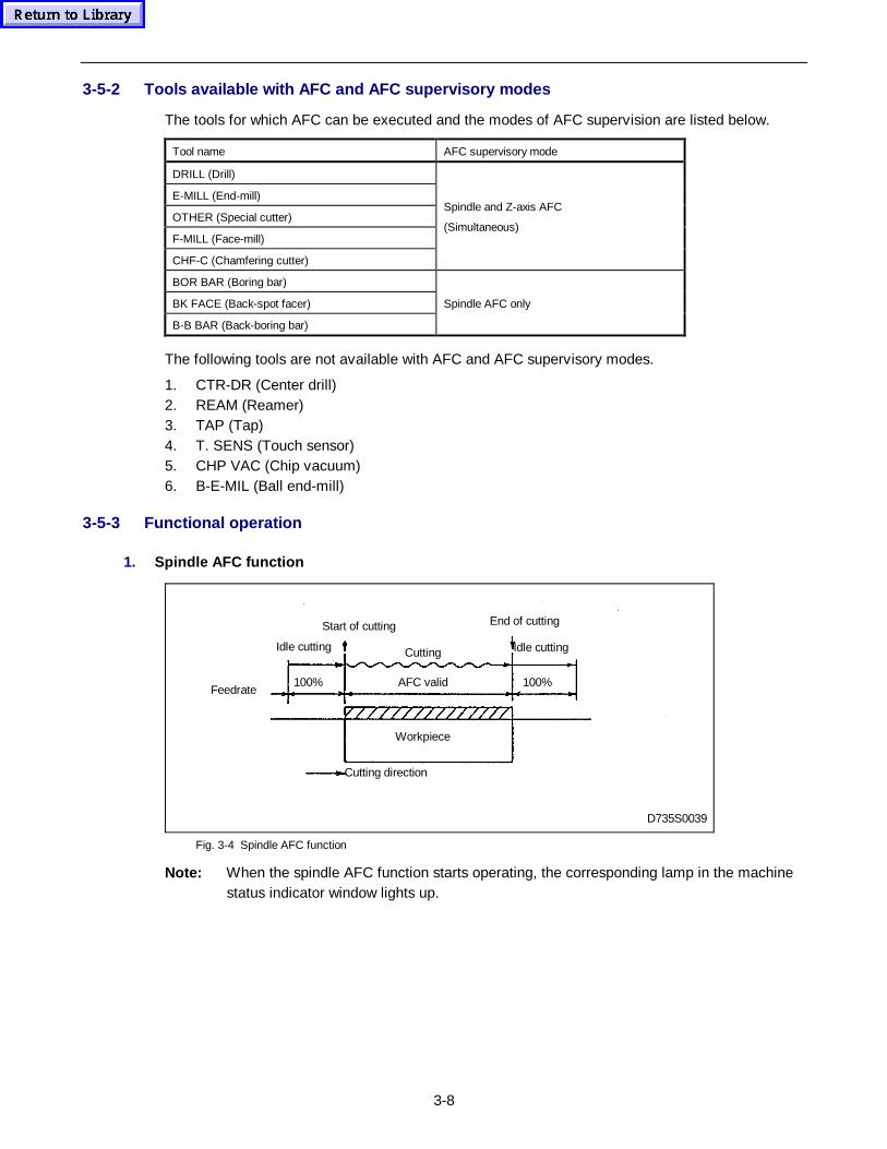
3-8
3-5-2 Tools available with AFC and AFC supervisory modes
The tools for which AFC can be executed and the modes of AFC supervision are listed below.
Tool name AFC supervisory mode
DRILL (Drill)
E-MILL (End-mill)
OTHER (Special cutter)
F-MILL (Face-mill)
CHF-C (Chamfering cutter)
Spindle and Z-axis AFC
(Simultaneous)
BOR BAR (Boring bar)
BK FACE (Back-spot facer)
B-B BAR (Back-boring bar)
Spindle AFC only
The following tools are not available with AFC and AFC supervisory modes.
1. CTR-DR (Center drill)2. REAM (Reamer)3. TAP (Tap)4. T. SENS (Touch sensor)5. CHP VAC (Chip vacuum)6. B-E-MIL (Ball end-mill)
3-5-3 Functional operation
1. Spindle AFC function
Start of cutting
Cutting
End of cutting
Idle cutting
Workpiece
100%
Cutting direction
AFC valid100%Feedrate
D735S0039
Idle cutting
Fig. 3-4 Spindle AFC function
Note: When the spindle AFC function starts operating, the corresponding lamp in the machinestatus indicator window lights up.
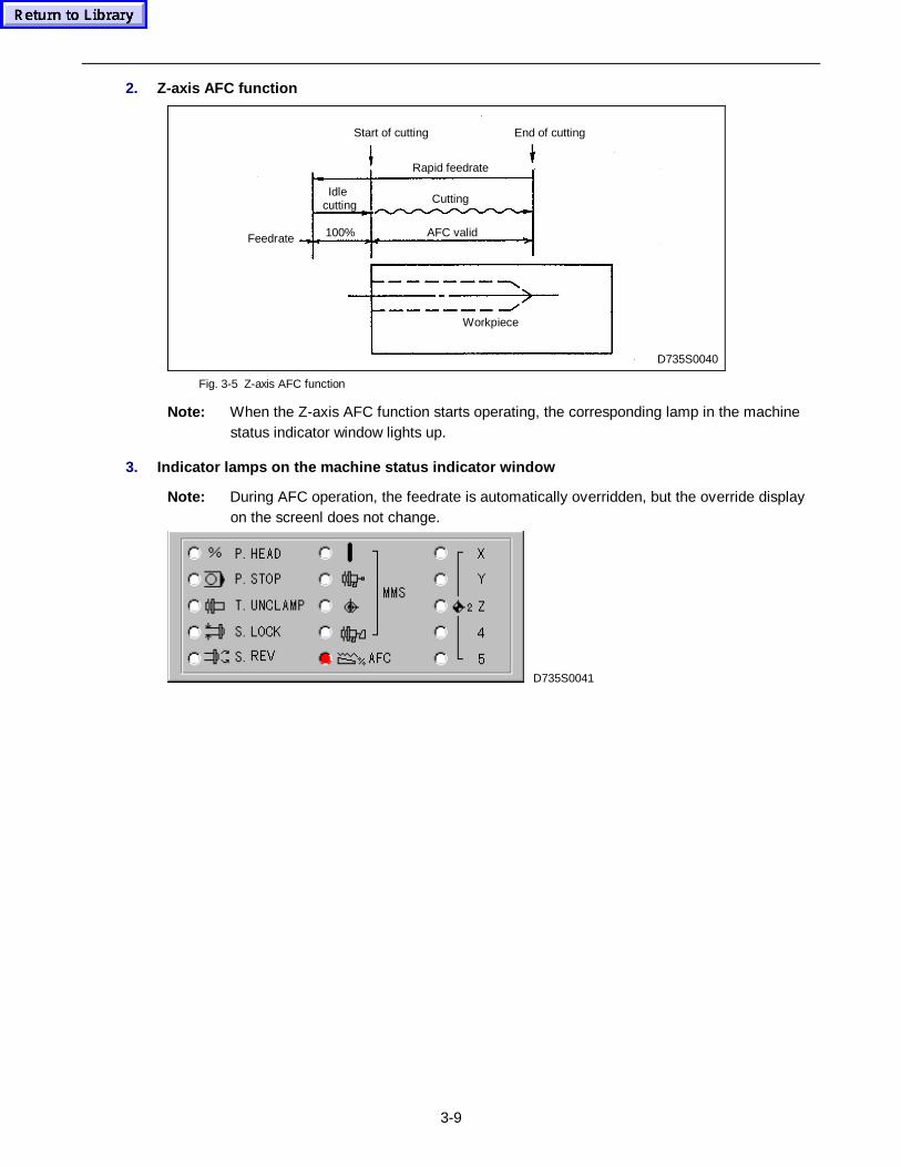
3-9
2. Z-axis AFC function
100% AFC valid
End of cuttingStart of cutting
Cutting
Rapid feedrate
Idle cutting
Feedrate
Workpiece
D735S0040
Fig. 3-5 Z-axis AFC function
Note: When the Z-axis AFC function starts operating, the corresponding lamp in the machinestatus indicator window lights up.
3. Indicator lamps on the machine status indicator window
Note: During AFC operation, the feedrate is automatically overridden, but the override displayon the screenl does not change.
D735S0041

3-10
- NOTE -
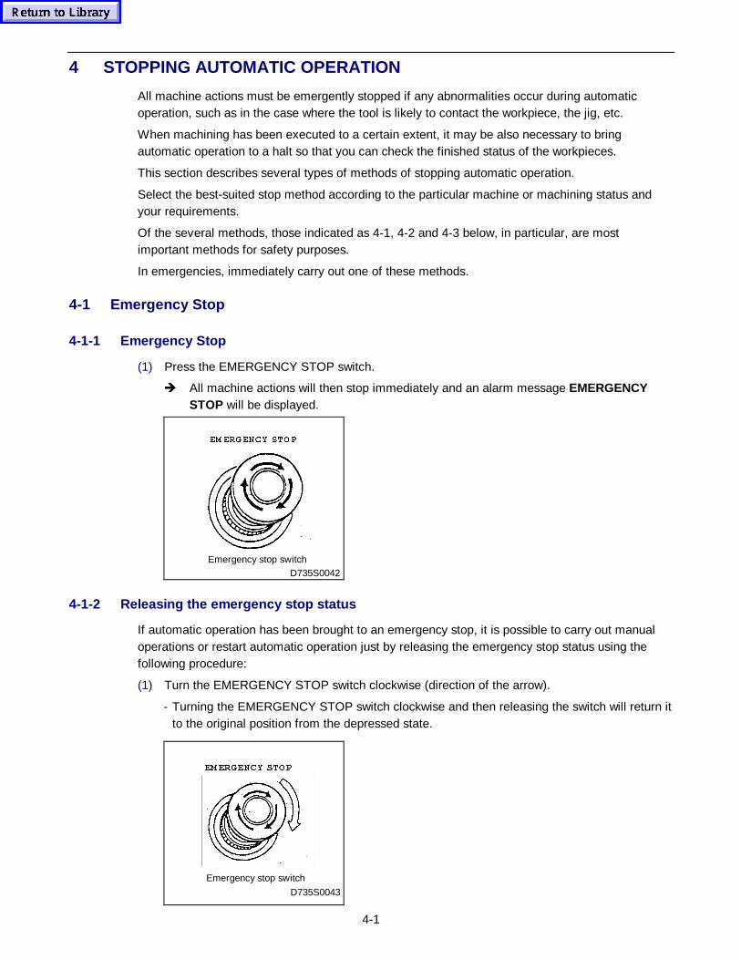
4-1
4 STOPPING AUTOMATIC OPERATION
All machine actions must be emergently stopped if any abnormalities occur during automaticoperation, such as in the case where the tool is likely to contact the workpiece, the jig, etc.
When machining has been executed to a certain extent, it may be also necessary to bringautomatic operation to a halt so that you can check the finished status of the workpieces.
This section describes several types of methods of stopping automatic operation.
Select the best-suited stop method according to the particular machine or machining status andyour requirements.
Of the several methods, those indicated as 4-1, 4-2 and 4-3 below, in particular, are mostimportant methods for safety purposes.
In emergencies, immediately carry out one of these methods.
4-1 Emergency Stop
4-1-1 Emergency Stop
(1) Press the EMERGENCY STOP switch.
Î All machine actions will then stop immediately and an alarm message EMERGENCYSTOP will be displayed.
D735S0042Emergency stop switch
(0 (5*(1&< 6723
4-1-2 Releasing the emergency stop status
If automatic operation has been brought to an emergency stop, it is possible to carry out manualoperations or restart automatic operation just by releasing the emergency stop status using thefollowing procedure:
(1) Turn the EMERGENCY STOP switch clockwise (direction of the arrow).
- Turning the EMERGENCY STOP switch clockwise and then releasing the switch will return itto the original position from the depressed state.
Emergency stop switch
D735S0043
(0 (5*(1&< 6723
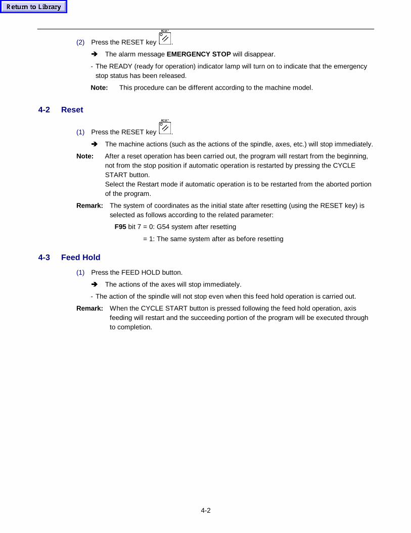
4-2
(2) Press the RESET key .
Î The alarm message EMERGENCY STOP will disappear.
- The READY (ready for operation) indicator lamp will turn on to indicate that the emergencystop status has been released.
Note: This procedure can be different according to the machine model.
4-2 Reset
(1) Press the RESET key .
Î The machine actions (such as the actions of the spindle, axes, etc.) will stop immediately.
Note: After a reset operation has been carried out, the program will restart from the beginning,not from the stop position if automatic operation is restarted by pressing the CYCLESTART button.Select the Restart mode if automatic operation is to be restarted from the aborted portionof the program.
Remark: The system of coordinates as the initial state after resetting (using the RESET key) isselected as follows according to the related parameter:
F95 bit 7 = 0: G54 system after resetting
= 1: The same system after as before resetting
4-3 Feed Hold
(1) Press the FEED HOLD button.
Î The actions of the axes will stop immediately.
- The action of the spindle will not stop even when this feed hold operation is carried out.
Remark: When the CYCLE START button is pressed following the feed hold operation, axisfeeding will restart and the succeeding portion of the program will be executed throughto completion.
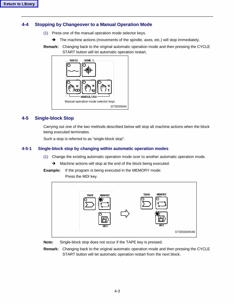
4-3
4-4 Stopping by Changeover to a Manual Operation Mode
(1) Press one of the manual operation mode selector keys.
Î The machine actions (movements of the spindle, axes, etc.) will stop immediately.
Remark: Changing back to the original automatic operation mode and then pressing the CYCLESTART button will let automatic operation restart.
D735S0044
RAPID HOME 1
HANDLE/JOG
Manual operation mode selector keys
4-5 Single-block Stop
Carrying out one of the two methods described below will stop all machine actions when the blockbeing executed terminates.
Such a stop is referred to as “single-block stop”.
4-5-1 Single-block stop by changing within automatic operation modes
(1) Change the existing automatic operation mode over to another automatic operation mode.
Î Machine actions will stop at the end of the block being executed.
Example: If the program is being executed in the MEMORY mode:
Press the MDI key.
D735S0045/46
TAPE MEMORY
MDI
TAPE MEMORY
MDI
Note: Single-block stop does not occur if the TAPE key is pressed.
Remark: Changing back to the original automatic operation mode and then pressing the CYCLESTART button will let automatic operation restart from the next block.
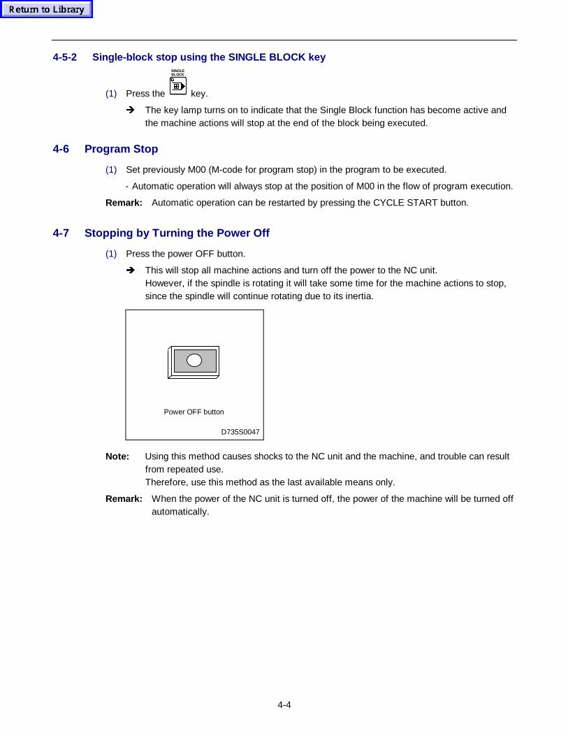
4-4
4-5-2 Single-block stop using the SINGLE BLOCK key
(1) Press the
SINGLEBLOCK
key.
Î The key lamp turns on to indicate that the Single Block function has become active andthe machine actions will stop at the end of the block being executed.
4-6 Program Stop
(1) Set previously M00 (M-code for program stop) in the program to be executed.
- Automatic operation will always stop at the position of M00 in the flow of program execution.
Remark: Automatic operation can be restarted by pressing the CYCLE START button.
4-7 Stopping by Turning the Power Off
(1) Press the power OFF button.
Î This will stop all machine actions and turn off the power to the NC unit.However, if the spindle is rotating it will take some time for the machine actions to stop,since the spindle will continue rotating due to its inertia.
D735S0047
Power OFF button
Note: Using this method causes shocks to the NC unit and the machine, and trouble can resultfrom repeated use.Therefore, use this method as the last available means only.
Remark: When the power of the NC unit is turned off, the power of the machine will be turned offautomatically.
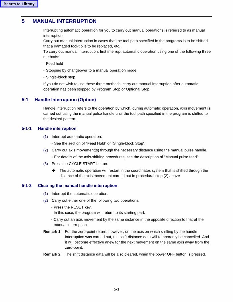
5-1
5 MANUAL INTERRUPTION
Interrupting automatic operation for you to carry out manual operations is referred to as manualinterruption.Carry out manual interruption in cases that the tool path specified in the programs is to be shifted,that a damaged tool-tip is to be replaced, etc.To carry out manual interruption, first interrupt automatic operation using one of the following threemethods:
- Feed hold
- Stopping by changeover to a manual operation mode
- Single-block stop
If you do not wish to use these three methods, carry out manual interruption after automaticoperation has been stopped by Program Stop or Optional Stop.
5-1 Handle Interruption (Option)
Handle interruption refers to the operation by which, during automatic operation, axis movement iscarried out using the manual pulse handle until the tool path specified in the program is shifted tothe desired pattern.
5-1-1 Handle interruption
(1) Interrupt automatic operation.
- See the section of “Feed Hold” or “Single-block Stop”.
(2) Carry out axis movement(s) through the necessary distance using the manual pulse handle.
- For details of the axis-shifting procedures, see the description of “Manual pulse feed”.
(3) Press the CYCLE START button.
Î The automatic operation will restart in the coordinates system that is shifted through thedistance of the axis movement carried out in procedural step (2) above.
5-1-2 Clearing the manual handle interruption
(1) Interrupt the automatic operation.
(2) Carry out either one of the following two operations.
- Press the RESET key.In this case, the program will return to its starting part.
- Carry out an axis movement by the same distance in the opposite direction to that of themanual interruption.
Remark 1: For the zero-point return, however, on the axis on which shifting by the handleinterruption was carried out, the shift distance data will temporarily be cancelled. Andit will become effective anew for the next movement on the same axis away from thezero-point.
Remark 2: The shift distance data will be also cleared, when the power OFF button is pressed.
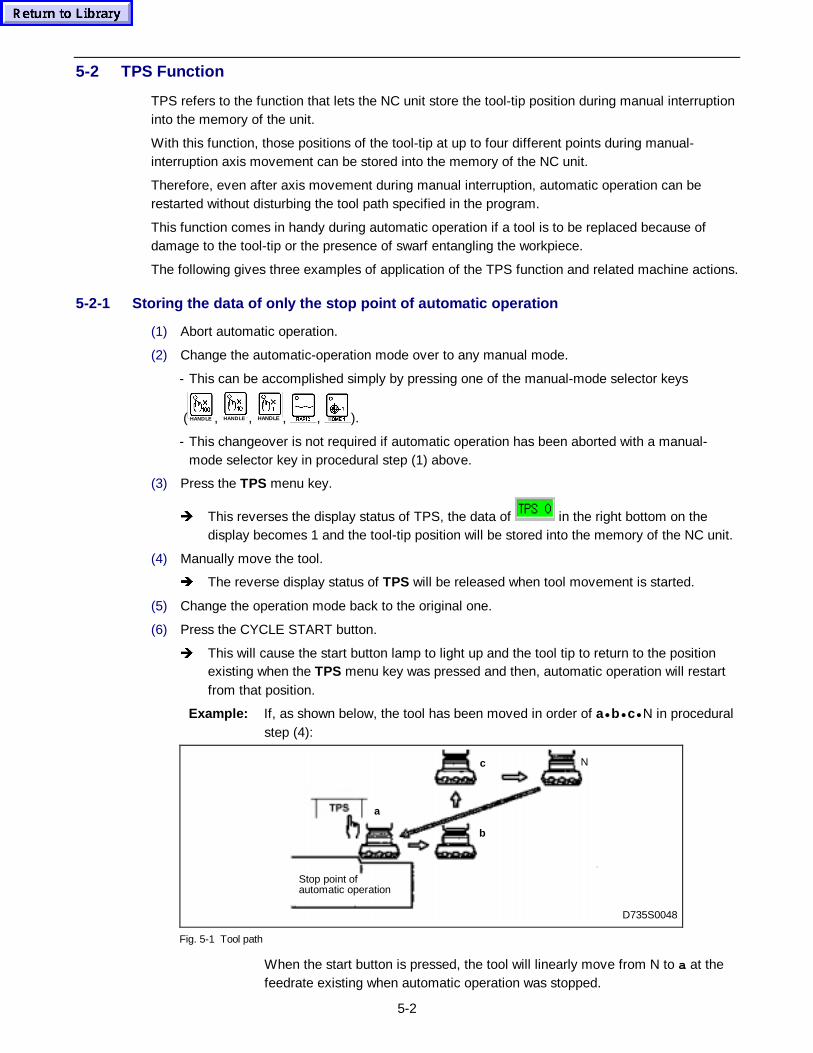
5-2
5-2 TPS Function
TPS refers to the function that lets the NC unit store the tool-tip position during manual interruptioninto the memory of the unit.
With this function, those positions of the tool-tip at up to four different points during manual-interruption axis movement can be stored into the memory of the NC unit.
Therefore, even after axis movement during manual interruption, automatic operation can berestarted without disturbing the tool path specified in the program.
This function comes in handy during automatic operation if a tool is to be replaced because ofdamage to the tool-tip or the presence of swarf entangling the workpiece.
The following gives three examples of application of the TPS function and related machine actions.
5-2-1 Storing the data of only the stop point of automatic operation
(1) Abort automatic operation.
(2) Change the automatic-operation mode over to any manual mode.
- This can be accomplished simply by pressing one of the manual-mode selector keys
( HANDLE , HANDLE , HANDLE , , ).
- This changeover is not required if automatic operation has been aborted with a manual-mode selector key in procedural step (1) above.
(3) Press the TPS menu key.
Î This reverses the display status of TPS, the data of in the right bottom on thedisplay becomes 1 and the tool-tip position will be stored into the memory of the NC unit.
(4) Manually move the tool.
Î The reverse display status of TPS will be released when tool movement is started.
(5) Change the operation mode back to the original one.
(6) Press the CYCLE START button.
Î This will cause the start button lamp to light up and the tool tip to return to the positionexisting when the TPS menu key was pressed and then, automatic operation will restartfrom that position.
Example: If, as shown below, the tool has been moved in order of a• b• c• N in proceduralstep (4):
D735S0048
N
a
b
c
Stop point ofautomatic operation
Fig. 5-1 Tool path
When the start button is pressed, the tool will linearly move from N to a at thefeedrate existing when automatic operation was stopped.
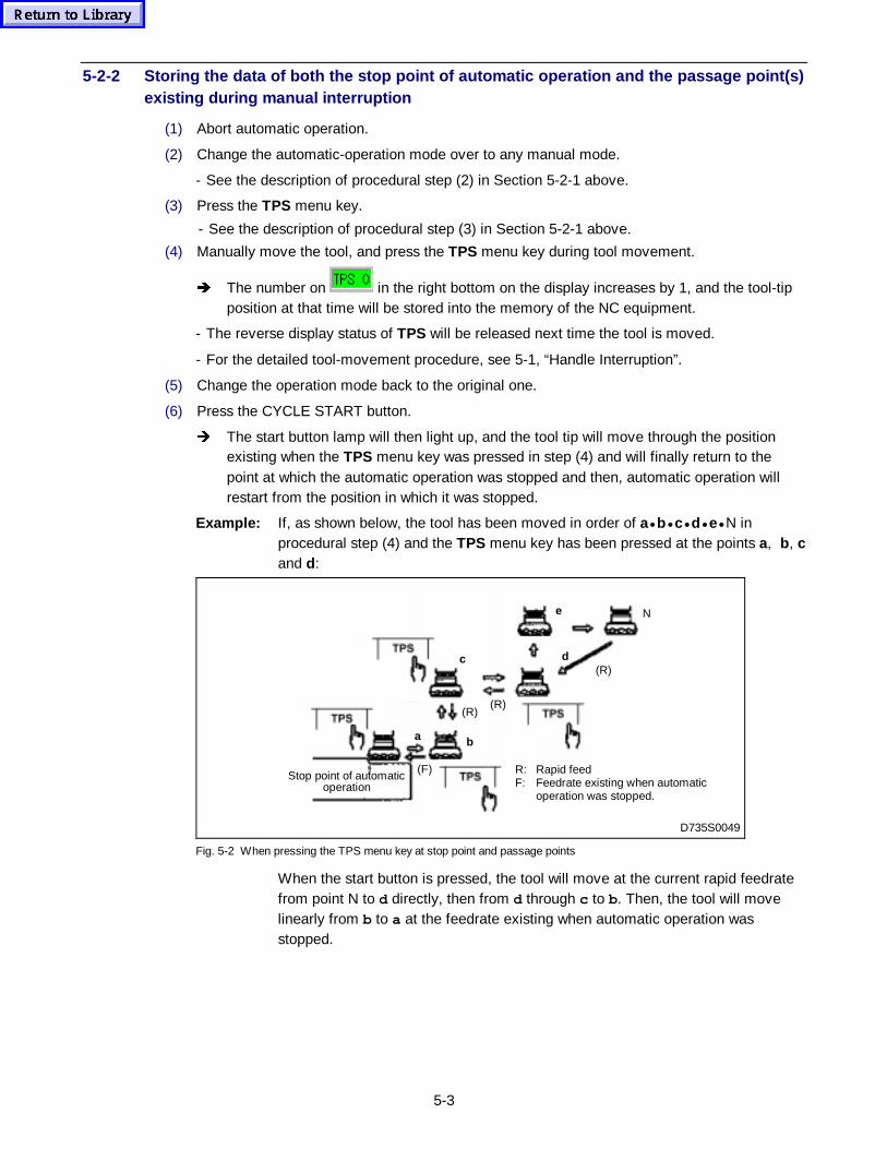
5-3
5-2-2 Storing the data of both the stop point of automatic operation and the passage point(s)existing during manual interruption
(1) Abort automatic operation.
(2) Change the automatic-operation mode over to any manual mode.
- See the description of procedural step (2) in Section 5-2-1 above.
(3) Press the TPS menu key.
- See the description of procedural step (3) in Section 5-2-1 above.
(4) Manually move the tool, and press the TPS menu key during tool movement.
Î The number on in the right bottom on the display increases by 1, and the tool-tipposition at that time will be stored into the memory of the NC equipment.
- The reverse display status of TPS will be released next time the tool is moved.
- For the detailed tool-movement procedure, see 5-1, “Handle Interruption”.
(5) Change the operation mode back to the original one.
(6) Press the CYCLE START button.
Î The start button lamp will then light up, and the tool tip will move through the positionexisting when the TPS menu key was pressed in step (4) and will finally return to thepoint at which the automatic operation was stopped and then, automatic operation willrestart from the position in which it was stopped.
Example: If, as shown below, the tool has been moved in order of a• b• c• d• e• N inprocedural step (4) and the TPS menu key has been pressed at the points a, b, cand d:
R: Rapid feedF: Feedrate existing when automatic
operation was stopped.
(F)
a b
(R)(R)
N
D735S0049
(R)
e
dc
Stop point of automaticoperation
Fig. 5-2 When pressing the TPS menu key at stop point and passage points
When the start button is pressed, the tool will move at the current rapid feedratefrom point N to d directly, then from d through c to b. Then, the tool will movelinearly from b to a at the feedrate existing when automatic operation wasstopped.
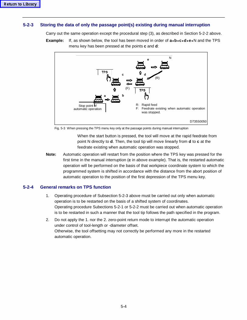
5-4
5-2-3 Storing the data of only the passage point(s) existing during manual interruption
Carry out the same operation except the procedural step (3), as described in Section 5-2-2 above.
Example: If, as shown below, the tool has been moved in order of a• b• c• d• e• N and the TPSmenu key has been pressed at the points c and d:
R: Rapid feedF: Feedrate existing when automatic operation
was stopped.
Ne
d(R)
(F)
ba
c
Stop point ofautomatic operation
D735S0050
Fig. 5-3 When pressing the TPS menu key only at the passage points during manual interruption
When the start button is pressed, the tool will move at the rapid feedrate frompoint N directly to d. Then, the tool tip will move linearly from d to c at thefeedrate existing when automatic operation was stopped.
Note: Automatic operation will restart from the position where the TPS key was pressed for thefirst time in the manual interruption (c in above example). That is, the restarted automaticoperation will be performed on the basis of that workpiece coordinate system to which theprogrammed system is shifted in accordance with the distance from the abort position ofautomatic operation to the position of the first depression of the TPS menu key.
5-2-4 General remarks on TPS function
1. Operating procedure of Subsection 5-2-3 above must be carried out only when automaticoperation is to be restarted on the basis of a shifted system of coordinates.Operating procedure Subections 5-2-1 or 5-2-2 must be carried out when automatic operationis to be restarted in such a manner that the tool tip follows the path specified in the program.
2. Do not apply the 1. nor the 2. zero-point return mode to interrupt the automatic operationunder control of tool-length or -diameter offset.Otherwise, the tool offsetting may not correctly be performed any more in the restartedautomatic operation.
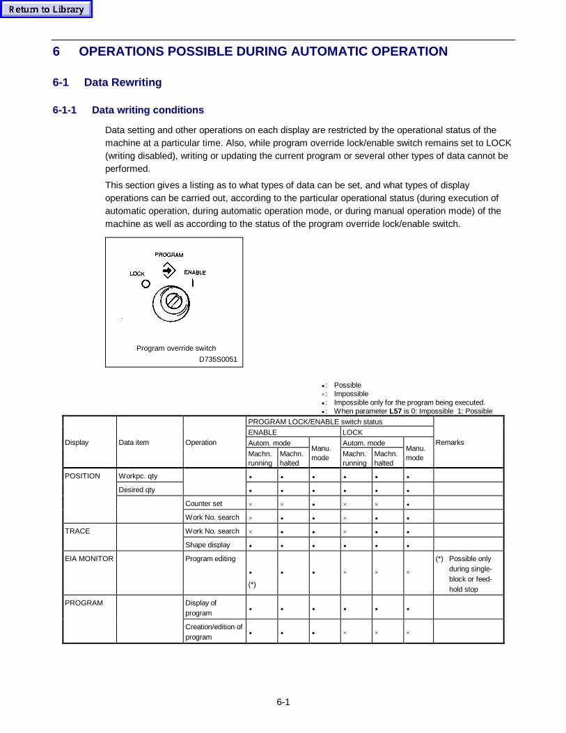
6-1
6 OPERATIONS POSSIBLE DURING AUTOMATIC OPERATION
6-1 Data Rewriting
6-1-1 Data writing conditions
Data setting and other operations on each display are restricted by the operational status of themachine at a particular time. Also, while program override lock/enable switch remains set to LOCK(writing disabled), writing or updating the current program or several other types of data cannot beperformed.
This section gives a listing as to what types of data can be set, and what types of displayoperations can be carried out, according to the particular operational status (during execution ofautomatic operation, during automatic operation mode, or during manual operation mode) of themachine as well as according to the status of the program override lock/enable switch.
D735S0051
Program override switch
• : Possible×: Impossible• : Impossible only for the program being executed.• : When parameter L57 is 0: Impossible 1: Possible
PROGRAM LOCK/ENABLE switch status
ENABLE LOCK
Autom. mode Autom. modeDisplay Data item Operation
Machn.running
Machn.halted
Manu.mode Machn.
runningMachn.halted
Manu.mode
Remarks
Workpc. qty • • • • • •
Desired qty • • • • • •
Counter set × × • × × •
POSITION
Work No. search × • • × • •
Work No. search × • • × • •TRACE
Shape display • • • • • •
EIA MONITOR Program editing
•
(*)
• • × × ×
(*) Possible onlyduring single-block or feed-hold stop
Display ofprogram
• • • • • •PROGRAM
Creation/edition ofprogram
• • • × × ×
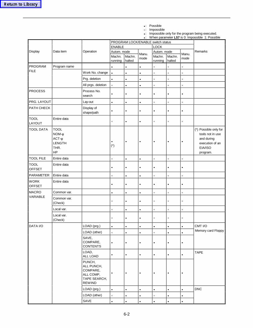
6-2
• : Possible×: Impossible• : Impossible only for the program being executed.• : When parameter L57 is 0: Impossible 1: Possible
PROGRAM LOCK/ENABLE switch status
ENABLE LOCK
Autom. mode Autom. modeDisplay Data item Operation
Machn.running
Machn.halted
Manu.mode Machn.
runningMachn.halted
Manu.mode
Remarks
Program name • • • × × ×
Work No. change • • • × × ×
Prg. deletion • • • × × ×
PROGRAMFILE
All prgs. deletion × • • × × ×
PROCESS Process No.search
• • • • • •
PRG. LAYOUT Lay-out • • • × × ×
PATH CHECK Display ofshape/path
• • • • • •
TOOLLAYOUT
Entire data× • • × × ×
TOOL DATA TOOLNOM-φACT-φLENGTHTHR.HP
•
(*)• • • • •
(*) Possible only fortools not in useand duringexecution of anEIA/ISOprogram.
TOOL FILE Entire data × • • × × ×
TOOLOFFSET
Entire data• • • • • •
PARAMETER Entire data × • • × × ×
WORKOFFSET
Entire data• • • • • •
Common var. • • • × × ×
Common var.(Check)
× • • × × ×
Local var. × • • × × ×
MACROVARIABLE
Local var.(Check)
× • • × × ×
LOAD (prg.) • • • • • •
LOAD (other) × • • × • •
SAVE,COMPARE,CONTENTS
• • • • • •
CMT I/OMemory card Floppy
LOAD,ALL LOAD • • • • • •
PUNCH,ALL PUNCH,COMPARE,ALL COMP,TAPE SEARCH,REWIND
• • • • • •
TAPE
LOAD (prg.) • • • • • •
LOAD (other) × • • × • •
DATA I/O
SAVE • • • • • •
DNC

Section 5:
Appendix

Notes:
C-1
TABLE OF CONTENTS(APPENDIX)
Page
1 STANDARD SPECIFICATIONS OF THE MACHINE.............................1-1
1-1 Major Machine Specifications ............................................................................ 1-1
1-2 Stroke Diagram and Spindle Interference Diagrams.......................................... 1-3
1-3 Spindle Speed-Power-Torque Diagrams............................................................ 1-4
1-4 Table Dimensions .............................................................................................. 1-5
1-5 Sub table Dimensions ........................................................................................ 1-5
1-6 Workpiece Interference Diagram........................................................................ 1-6
2 ALARM LIST ...........................................................................................2-1
3 M CODE LIST .........................................................................................3-1

C-2
- MEMO -
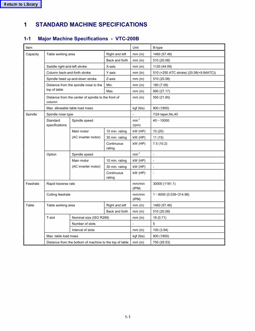
1-1
1 STANDARD MACHINE SPECIFICATIONS
1-1 Major Machine Specifications - VTC-200BItem Unit B-type
Right and left mm (in) 1460 (57.48)Table working area
Back and forth mm (in) 510 (20.08)
Saddle right-and-left stroke X-axis mm (in) 1120 (44.09)
Column back-and-forth stroke Y-axis mm (in) 510 (+250 ATC stroke) (20.08(+9.84ATC))
Spindle head up-and-down stroke Z-axis mm (in) 510 (20.08)
Min. mm (in) 180 (7.09)Distance from the spindle nose to thetop of table Max. mm (in) 690 (27.17)
Distance from the center of spindle to the front ofcolumn
mm (in) 550 (21.65)
Capacity
Max. allowable table load mass kgf (lbs) 800 (1800)
Spindle nose type - 7/24 taper,No,40
Spindle speed min-1
(rpm)40~10000
10 min. rating kW (HP) 15 (20)
30 min. rating kW (HP) 11 (15)
Standardspecifications
Main motor
(AC inverter motor)
Continuousrating
kW (HP) 7.5 (10.2)
Spindle speed min-1 -
10 min. rating kW (HP) -
30 min. rating kW (HP) -
Spindle
Option
Main motor
(AC inverter motor)
Continuousrating
kW (HP) -
Rapid traverse rate mm/min(lPM)
30000 (1181.1)Feedrate
Cutting feedrate mm/min(lPM)
1~8000 (0.039~314.96)
Right and left mm (in) 1460 (57.48)Table working area
Back and forth mm (in) 510 (20.08)
Nominal size (ISO R299) mm (in) 18 (0.71)
Number of slots - 5
T-slot
Interval of slots mm (in) 100 (3.94)
Max. table load mass kgf (lbs) 800 (1800)
Table
Distance from the bottom of machine to the top of table mm (in) 750 (29.53)
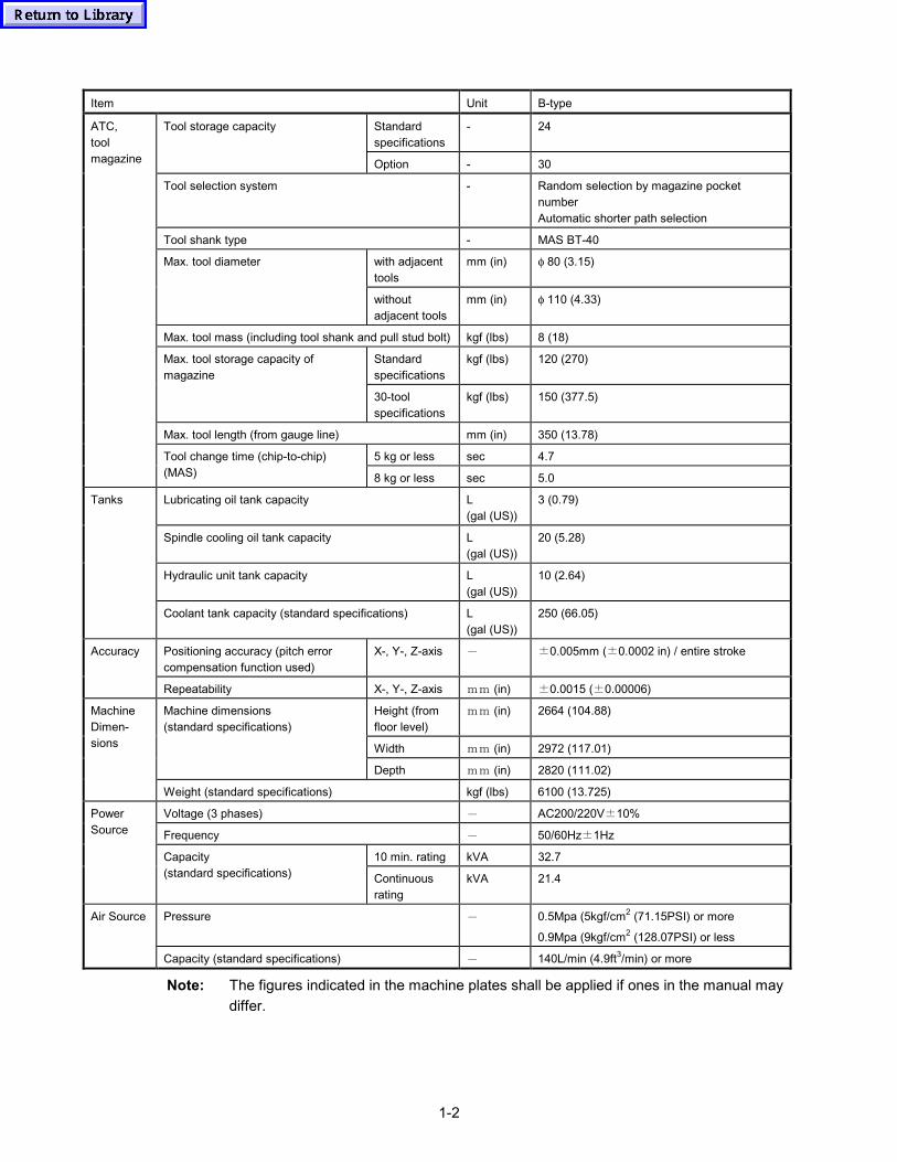
1-2
Item Unit B-type
Standardspecifications
- 24Tool storage capacity
Option - 30
Tool selection system - Random selection by magazine pocketnumberAutomatic shorter path selection
Tool shank type - MAS BT-40
with adjacenttools
mm (in) φ 80 (3.15)Max. tool diameter
withoutadjacent tools
mm (in) φ 110 (4.33)
Max. tool mass (including tool shank and pull stud bolt) kgf (lbs) 8 (18)
Standardspecifications
kgf (lbs) 120 (270)Max. tool storage capacity ofmagazine
30-toolspecifications
kgf (lbs) 150 (377.5)
Max. tool length (from gauge line) mm (in) 350 (13.78)
5 kg or less sec 4.7
ATC,toolmagazine
Tool change time (chip-to-chip)(MAS) 8 kg or less sec 5.0
Lubricating oil tank capacity L(gal (US))
3 (0.79)
Spindle cooling oil tank capacity L(gal (US))
20 (5.28)
Hydraulic unit tank capacity L(gal (US))
10 (2.64)
Tanks
Coolant tank capacity (standard specifications) L(gal (US))
250 (66.05)
Positioning accuracy (pitch errorcompensation function used)
X-, Y-, Z-axis - ±0.005mm (±0.0002 in) / entire strokeAccuracy
Repeatability X-, Y-, Z-axis mm (in) ±0.0015 (±0.00006)
Height (fromfloor level)
mm (in) 2664 (104.88)
Width mm (in) 2972 (117.01)
Machine dimensions(standard specifications)
Depth mm (in) 2820 (111.02)
MachineDimen-sions
Weight (standard specifications) kgf (lbs) 6100 (13.725)
Voltage (3 phases) - AC200/220V±10%
Frequency - 50/60Hz±1Hz
10 min. rating kVA 32.7
PowerSource
Capacity(standard specifications) Continuous
ratingkVA 21.4
Pressure - 0.5Mpa (5kgf/cm2 (71.15PSI) or more
0.9Mpa (9kgf/cm2 (128.07PSI) or less
Air Source
Capacity (standard specifications) - 140L/min (4.9ft3/min) or more
Note: The figures indicated in the machine plates shall be applied if ones in the manual maydiffer.
1-3
1-2 Stroke Diagram and Spindle Interference Diagrams - VTC-200B
A
B
C
D
E
F
G
Z-axis strokeY-axis strokeX-axis stroke
ATC stroke
Spindle nose
Pallet topsurface
ATC position
Y-axis zero-pointX-axis zero-point
Z-axiszero-point
+-
+
-
+-
Fig. 1-1 Stroke Diagram
Unit: mm (in.)
Stroke VTC-200B
A 1120 (44.09)
B 560 (22.05)
C 510 (20.08)
D 255 (10.04)
E 250 (9.84)
F 510 (20.08)
G 180 (7.09)
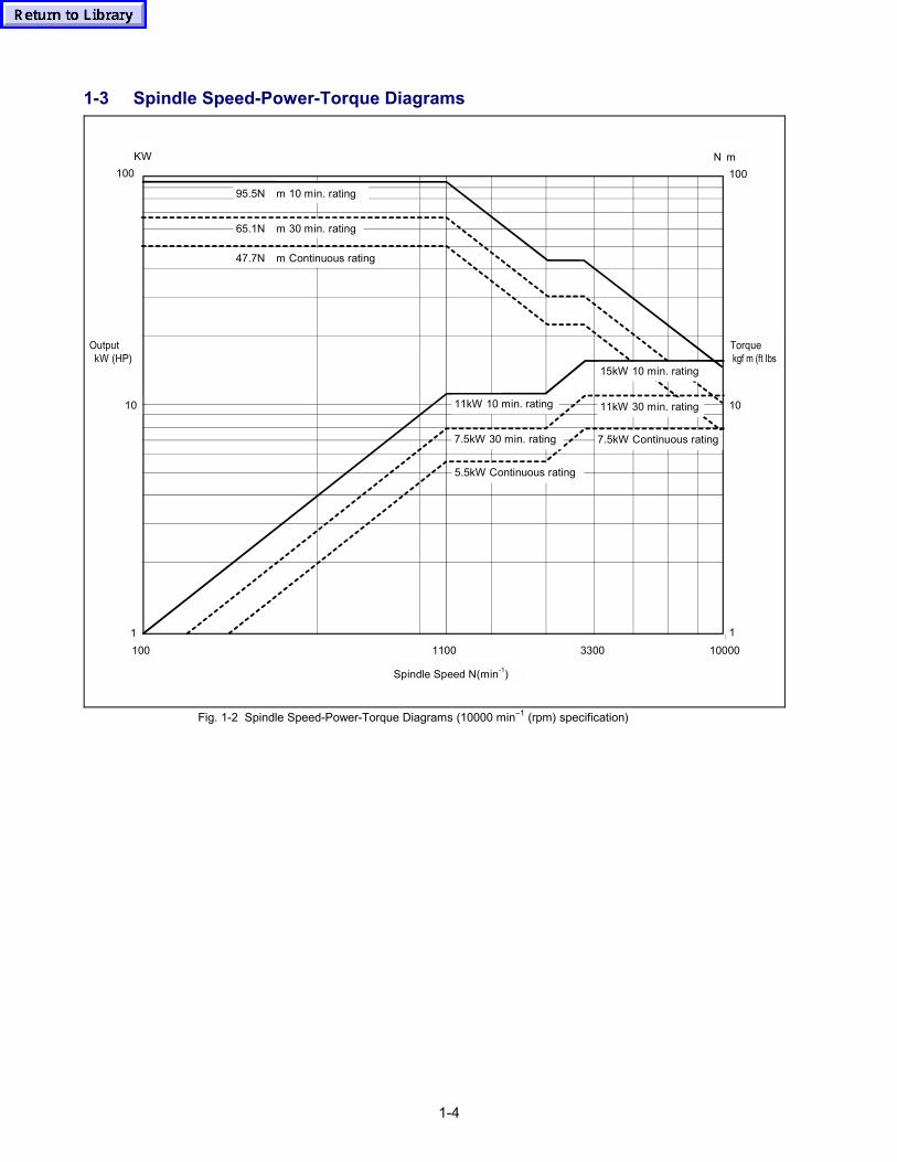
1-4
1-3 Spindle Speed-Power-Torque Diagrams
10000330011001001
10
100
Spindle Speed N(min-1)
OutputkW (HP)
Torquekgf m (ft Ibs
KW
7.5kW Continuous rating
11kW 30 min. rating
15kW 10 min. rating
5.5kW Continuous rating
7.5kW 30 min. rating
11kW 10 min. rating
95.5N m 10 min. rating
65.1N m 30 min. rating
47.7N m Continuous rating
N m100
10
1
Fig. 1-2 Spindle Speed-Power-Torque Diagrams (10000 min–1 (rpm) specification)
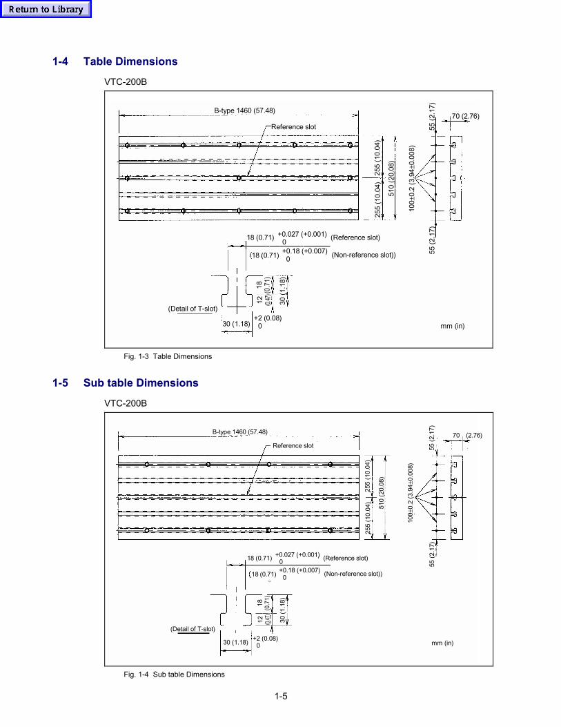
1-5
1-4 Table Dimensions
VTC-200B
70 (2.76)
55 (2
.17)
55 (2
.17)
100 ±
0.2
(3.9
4 ±0.
008)
510
(20.
08)
255
(10.
04)
255
(10.
04)
30 (1
.18)
12 (0.47
)18 (0.7
1)
(Non-reference slot))
(Reference slot)
+0.18 (+0.007)
+0.027 (+0.001)
(Detail of T-slot)
Reference slot
B-type 1460 (57.48)
0
0
+2 (0.08)0
18 (0.71)
18 (0.71)
30 (1.18) mm (in)
Fig. 1-3 Table Dimensions
1-5 Sub table Dimensions
VTC-200B
(Detail of T-slot)
70 (2.76)55
(2.1
7)55
(2.1
7)
100±
0.2
(3.9
4±0.
008)
510
(20.
08)
255
(10.
04)
255
(10.
04)
30 (1
.18)
(Non-reference slot))
(Reference slot)
+0.18 (+0.007)
+0.027 (+0.001)
Reference slot
B-type 1460 (57.48)
0
0
+2 (0.08)0
18 (0.71)
18 (0.71)
mm (in)30 (1.18)
12 (0.47
)18 (0.7
1)
Fig. 1-4 Sub table Dimensions
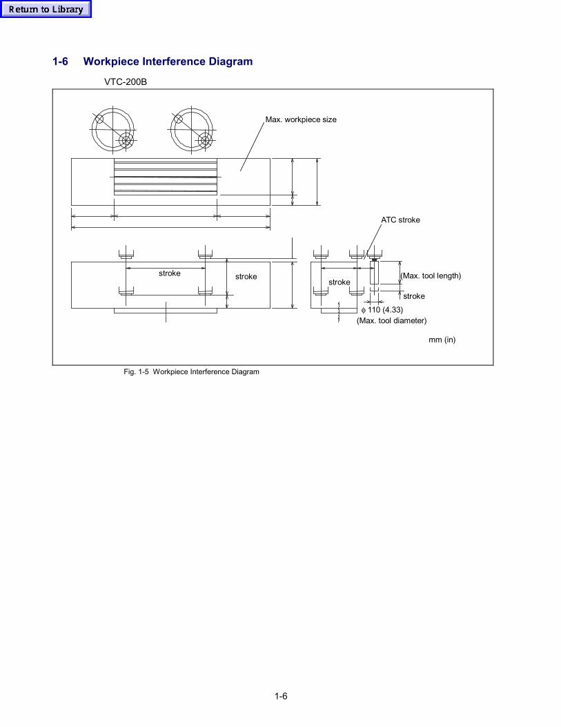
1-6
1-6 Workpiece Interference Diagram
VTC-200B
stroke
(Max. tool length)
φ 110 (4.33)(Max. tool diameter)
stroke stroke stroke
Max. workpiece size
ATC stroke
mm (in)
Fig. 1-5 Workpiece Interference Diagram
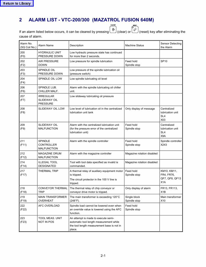
2-1
2 ALARM LIST - VTC-200/300 (MAZATROL FUSION 640M)
If an alarm listed below occurs, it can be cleared by pressing (clear) or (reset) key after eliminating thecause of alarm.
Alarm No.(SQ Coil No.)
Alarm Name Description Machine StatusSensor Detectingthe Alarm
200(F0)
HYDRAULIC UNITPRESSURE DOWN
Low hydraulic pressure state has continuedfor more than 2 seconds.
202(F2)
AIR PRESSUREDOWN
Low pressure for spindle lubrication Feed holdSpindle stop
SP10
203(F3)
SPINDLE OILPRESSURE DOWN
Low pressure of the spindle lubrication oil(pressure switch)
204(F4)
SPINDLE OIL LOW Low spindle lubricating oil level
206(F6)
SPINDLE LUB.CHILLER MALF.
Alarm with the spindle lubricating oil chillerunit.
207(F7)
IRREGULARSLIDEWAY OILPRESSURE
Low slideway lubricating oil pressure
208(F8)
SLIDEWAY OIL LOW Low level of lubrication oil in the centralizedlubrication unit tank
Only display of message Centralizedlubrication unitSL4X03
209(F9)
SLIDEWAY OILMALFUNCTION
Alarm with the centralized lubrication unit(for the pressure error of the centralizedlubrication unit)
Feed holdSpindle stop
Centralizedlubrication unitSL4X9A
211(F11)
SPINDLECONTROLLERMALFUNCTION
Alarm with the spindle controller Feed holdSpindle stop
Spindle controllerX243
212(F12)
MAGAZINE DRUMMALFUNCTION
Alarm with the magazine controller Magazine rotation disabled
214(F14)
ILLEGAL TOOLDESIGNATED
Tool with tool data specified as invalid iscommanded.
Magazine rotation disabled
217(F17)
THERMAL TRIP A thermal relay of auxiliary equipment motoris tripped.
The circuit protector in the 100 V line istripped.
Feed holdSpindle stop
KM10, KM11,FR4, FR76,QF7, QF8, QF13X1A
218(F18)
CONVEYOR THERMALTRIP
The thermal relay of chip conveyor orconveyor drive motor is tripped.
Only display of alarm FR13, FR113,X1B
219(F19)
MAIN TRANSFORMEROVERHEAT
The main transformer is exceeding 120°C(248°F).
Single blockSpindle stop
Main transformerX10
222(F22)
AFC OVERLOAD Spindle load cannot be lowered even whenan override value is lowered using the AFCfunction.
Feed holdSpindle stop
223(F23)
TOOL MEAS. UNITNOT IN POS
An attempt is made to execute semi-automatic tool length measurement whilethe tool length measurement base is not inplace.
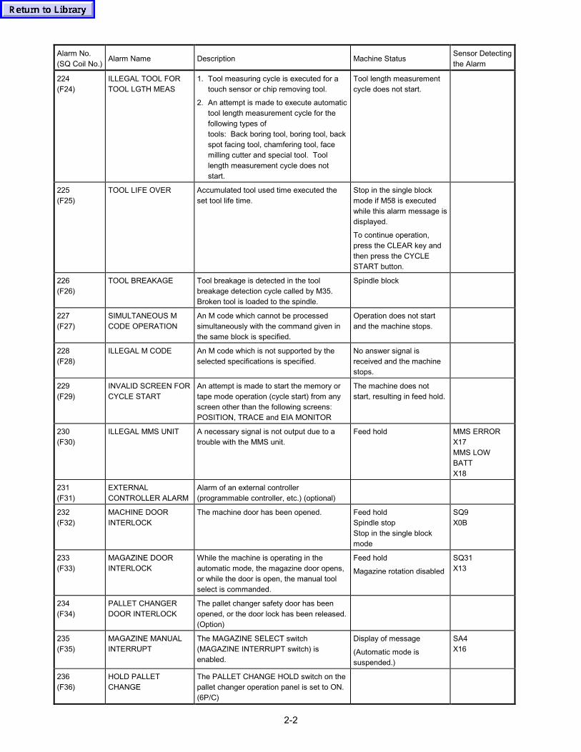
2-2
Alarm No.(SQ Coil No.)
Alarm Name Description Machine StatusSensor Detectingthe Alarm
224(F24)
ILLEGAL TOOL FORTOOL LGTH MEAS
1. Tool measuring cycle is executed for atouch sensor or chip removing tool.
2. An attempt is made to execute automatictool length measurement cycle for thefollowing types oftools: Back boring tool, boring tool, backspot facing tool, chamfering tool, facemilling cutter and special tool. Toollength measurement cycle does notstart.
Tool length measurementcycle does not start.
225(F25)
TOOL LIFE OVER Accumulated tool used time executed theset tool life time.
Stop in the single blockmode if M58 is executedwhile this alarm message isdisplayed.
To continue operation,press the CLEAR key andthen press the CYCLESTART button.
226(F26)
TOOL BREAKAGE Tool breakage is detected in the toolbreakage detection cycle called by M35.Broken tool is loaded to the spindle.
Spindle block
227(F27)
SIMULTANEOUS MCODE OPERATION
An M code which cannot be processedsimultaneously with the command given inthe same block is specified.
Operation does not startand the machine stops.
228(F28)
ILLEGAL M CODE An M code which is not supported by theselected specifications is specified.
No answer signal isreceived and the machinestops.
229(F29)
INVALID SCREEN FORCYCLE START
An attempt is made to start the memory ortape mode operation (cycle start) from anyscreen other than the following screens:POSITION, TRACE and EIA MONITOR
The machine does notstart, resulting in feed hold.
230(F30)
ILLEGAL MMS UNIT A necessary signal is not output due to atrouble with the MMS unit.
Feed hold MMS ERRORX17MMS LOWBATTX18
231(F31)
EXTERNALCONTROLLER ALARM
Alarm of an external controller(programmable controller, etc.) (optional)
232(F32)
MACHINE DOORINTERLOCK
The machine door has been opened. Feed holdSpindle stopStop in the single blockmode
SQ9X0B
233(F33)
MAGAZINE DOORINTERLOCK
While the machine is operating in theautomatic mode, the magazine door opens,or while the door is open, the manual toolselect is commanded.
Feed hold
Magazine rotation disabled
SQ31X13
234(F34)
PALLET CHANGERDOOR INTERLOCK
The pallet changer safety door has beenopened, or the door lock has been released.(Option)
235(F35)
MAGAZINE MANUALINTERRUPT
The MAGAZINE SELECT switch(MAGAZINE INTERRUPT switch) isenabled.
Display of message
(Automatic mode issuspended.)
SA4X16
236(F36)
HOLD PALLETCHANGE
The PALLET CHANGE HOLD switch on thepallet changer operation panel is set to ON.(6P/C)
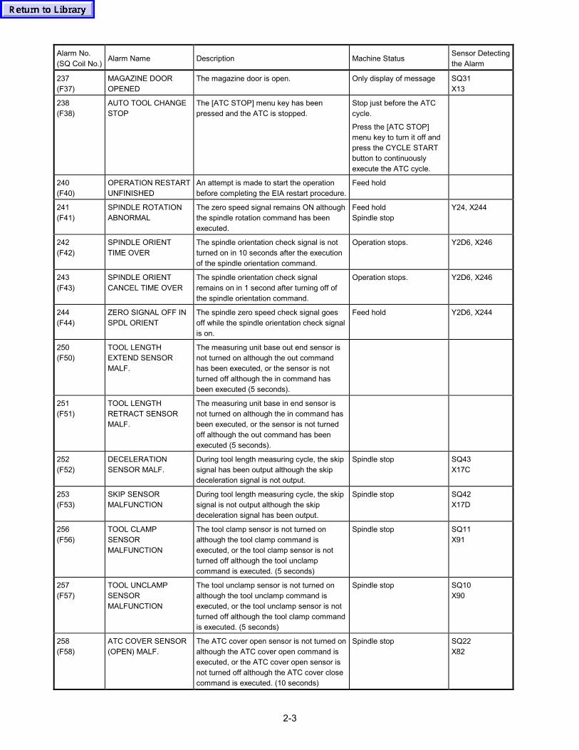
2-3
Alarm No.(SQ Coil No.)
Alarm Name Description Machine StatusSensor Detectingthe Alarm
237(F37)
MAGAZINE DOOROPENED
The magazine door is open. Only display of message SQ31X13
238(F38)
AUTO TOOL CHANGESTOP
The [ATC STOP] menu key has beenpressed and the ATC is stopped.
Stop just before the ATCcycle.
Press the [ATC STOP]menu key to turn it off andpress the CYCLE STARTbutton to continuouslyexecute the ATC cycle.
240(F40)
OPERATION RESTARTUNFINISHED
An attempt is made to start the operationbefore completing the EIA restart procedure.
Feed hold
241(F41)
SPINDLE ROTATIONABNORMAL
The zero speed signal remains ON althoughthe spindle rotation command has beenexecuted.
Feed holdSpindle stop
Y24, X244
242(F42)
SPINDLE ORIENTTIME OVER
The spindle orientation check signal is notturned on in 10 seconds after the executionof the spindle orientation command.
Operation stops. Y2D6, X246
243(F43)
SPINDLE ORIENTCANCEL TIME OVER
The spindle orientation check signalremains on in 1 second after turning off ofthe spindle orientation command.
Operation stops. Y2D6, X246
244(F44)
ZERO SIGNAL OFF INSPDL ORIENT
The spindle zero speed check signal goesoff while the spindle orientation check signalis on.
Feed hold Y2D6, X244
250(F50)
TOOL LENGTHEXTEND SENSORMALF.
The measuring unit base out end sensor isnot turned on although the out commandhas been executed, or the sensor is notturned off although the in command hasbeen executed (5 seconds).
251(F51)
TOOL LENGTHRETRACT SENSORMALF.
The measuring unit base in end sensor isnot turned on although the in command hasbeen executed, or the sensor is not turnedoff although the out command has beenexecuted (5 seconds).
252(F52)
DECELERATIONSENSOR MALF.
During tool length measuring cycle, the skipsignal has been output although the skipdeceleration signal is not output.
Spindle stop SQ43X17C
253(F53)
SKIP SENSORMALFUNCTION
During tool length measuring cycle, the skipsignal is not output although the skipdeceleration signal has been output.
Spindle stop SQ42X17D
256(F56)
TOOL CLAMPSENSORMALFUNCTION
The tool clamp sensor is not turned onalthough the tool clamp command isexecuted, or the tool clamp sensor is notturned off although the tool unclampcommand is executed. (5 seconds)
Spindle stop SQ11X91
257(F57)
TOOL UNCLAMPSENSORMALFUNCTION
The tool unclamp sensor is not turned onalthough the tool unclamp command isexecuted, or the tool unclamp sensor is notturned off although the tool clamp commandis executed. (5 seconds)
Spindle stop SQ10X90
258(F58)
ATC COVER SENSOR(OPEN) MALF.
The ATC cover open sensor is not turned onalthough the ATC cover open command isexecuted, or the ATC cover open sensor isnot turned off although the ATC cover closecommand is executed. (10 seconds)
Spindle stop SQ22X82
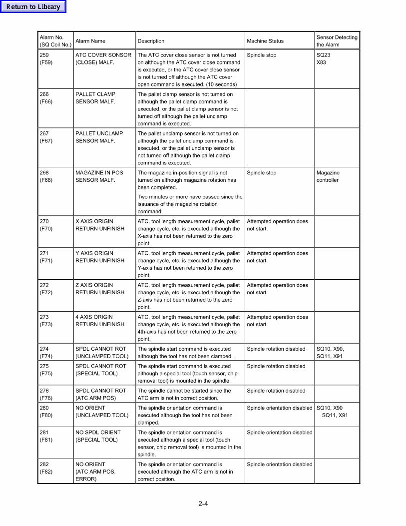
2-4
Alarm No.(SQ Coil No.)
Alarm Name Description Machine StatusSensor Detectingthe Alarm
259(F59)
ATC COVER SONSOR(CLOSE) MALF.
The ATC cover close sensor is not turnedon although the ATC cover close commandis executed, or the ATC cover close sensoris not turned off although the ATC coveropen command is executed. (10 seconds)
Spindle stop SQ23X83
266(F66)
PALLET CLAMPSENSOR MALF.
The pallet clamp sensor is not turned onalthough the pallet clamp command isexecuted, or the pallet clamp sensor is notturned off although the pallet unclampcommand is executed.
267(F67)
PALLET UNCLAMPSENSOR MALF.
The pallet unclamp sensor is not turned onalthough the pallet unclamp command isexecuted, or the pallet unclamp sensor isnot turned off although the pallet clampcommand is executed.
268(F68)
MAGAZINE IN POSSENSOR MALF.
The magazine in-position signal is notturned on although magazine rotation hasbeen completed.
Two minutes or more have passed since theissuance of the magazine rotationcommand.
Spindle stop Magazinecontroller
270(F70)
X AXIS ORIGINRETURN UNFINISH
ATC, tool length measurement cycle, palletchange cycle, etc. is executed although theX-axis has not been returned to the zeropoint.
Attempted operation doesnot start.
271(F71)
Y AXIS ORIGINRETURN UNFINISH
ATC, tool length measurement cycle, palletchange cycle, etc. is executed although theY-axis has not been returned to the zeropoint.
Attempted operation doesnot start.
272(F72)
Z AXIS ORIGINRETURN UNFINISH
ATC, tool length measurement cycle, palletchange cycle, etc. is executed although theZ-axis has not been returned to the zeropoint.
Attempted operation doesnot start.
273(F73)
4 AXIS ORIGINRETURN UNFINISH
ATC, tool length measurement cycle, palletchange cycle, etc. is executed although the4th-axis has not been returned to the zeropoint.
Attempted operation doesnot start.
274(F74)
SPDL CANNOT ROT(UNCLAMPED TOOL)
The spindle start command is executedalthough the tool has not been clamped.
Spindle rotation disabled SQ10, X90,SQ11, X91
275(F75)
SPDL CANNOT ROT(SPECIAL TOOL)
The spindle start command is executedalthough a special tool (touch sensor, chipremoval tool) is mounted in the spindle.
Spindle rotation disabled
276(F76)
SPDL CANNOT ROT(ATC ARM POS)
The spindle cannot be started since theATC arm is not in correct position.
Spindle rotation disabled
280(F80)
NO ORIENT(UNCLAMPED TOOL)
The spindle orientation command isexecuted although the tool has not beenclamped.
Spindle orientation disabled SQ10, X90 SQ11, X91
281(F81)
NO SPDL ORIENT(SPECIAL TOOL)
The spindle orientation command isexecuted although a special tool (touchsensor, chip removal tool) is mounted in thespindle.
Spindle orientation disabled
282(F82)
NO ORIENT(ATC ARM POS.ERROR)
The spindle orientation command isexecuted although the ATC arm is not incorrect position.
Spindle orientation disabled
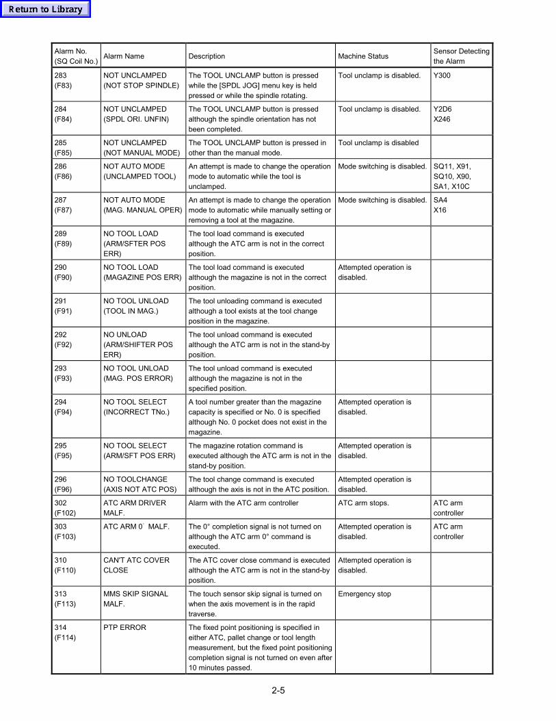
2-5
Alarm No.(SQ Coil No.)
Alarm Name Description Machine StatusSensor Detectingthe Alarm
283(F83)
NOT UNCLAMPED(NOT STOP SPINDLE)
The TOOL UNCLAMP button is pressedwhile the [SPDL JOG] menu key is heldpressed or while the spindle rotating.
Tool unclamp is disabled. Y300
284(F84)
NOT UNCLAMPED(SPDL ORI. UNFIN)
The TOOL UNCLAMP button is pressedalthough the spindle orientation has notbeen completed.
Tool unclamp is disabled. Y2D6X246
285(F85)
NOT UNCLAMPED(NOT MANUAL MODE)
The TOOL UNCLAMP button is pressed inother than the manual mode.
Tool unclamp is disabled
286(F86)
NOT AUTO MODE(UNCLAMPED TOOL)
An attempt is made to change the operationmode to automatic while the tool isunclamped.
Mode switching is disabled. SQ11, X91,SQ10, X90,SA1, X10C
287(F87)
NOT AUTO MODE(MAG. MANUAL OPER)
An attempt is made to change the operationmode to automatic while manually setting orremoving a tool at the magazine.
Mode switching is disabled. SA4X16
289(F89)
NO TOOL LOAD(ARM/SFTER POSERR)
The tool load command is executedalthough the ATC arm is not in the correctposition.
290(F90)
NO TOOL LOAD(MAGAZINE POS ERR)
The tool load command is executedalthough the magazine is not in the correctposition.
Attempted operation isdisabled.
291(F91)
NO TOOL UNLOAD(TOOL IN MAG.)
The tool unloading command is executedalthough a tool exists at the tool changeposition in the magazine.
292(F92)
NO UNLOAD(ARM/SHIFTER POSERR)
The tool unload command is executedalthough the ATC arm is not in the stand-byposition.
293(F93)
NO TOOL UNLOAD(MAG. POS ERROR)
The tool unload command is executedalthough the magazine is not in thespecified position.
294(F94)
NO TOOL SELECT(INCORRECT TNo.)
A tool number greater than the magazinecapacity is specified or No. 0 is specifiedalthough No. 0 pocket does not exist in themagazine.
Attempted operation isdisabled.
295(F95)
NO TOOL SELECT(ARM/SFT POS ERR)
The magazine rotation command isexecuted although the ATC arm is not in thestand-by position.
Attempted operation isdisabled.
296(F96)
NO TOOLCHANGE(AXIS NOT ATC POS)
The tool change command is executedalthough the axis is not in the ATC position.
Attempted operation isdisabled.
302(F102)
ATC ARM DRIVERMALF.
Alarm with the ATC arm controller ATC arm stops. ATC armcontroller
303(F103)
ATC ARM 0゚ MALF. The 0° completion signal is not turned onalthough the ATC arm 0° command isexecuted.
Attempted operation isdisabled.
ATC armcontroller
310(F110)
CAN'T ATC COVERCLOSE
The ATC cover close command is executedalthough the ATC arm is not in the stand-byposition.
Attempted operation isdisabled.
313(F113)
MMS SKIP SIGNALMALF.
The touch sensor skip signal is turned onwhen the axis movement is in the rapidtraverse.
Emergency stop
314(F114)
PTP ERROR The fixed point positioning is specified ineither ATC, pallet change or tool lengthmeasurement, but the fixed point positioningcompletion signal is not turned on even after10 minutes passed.
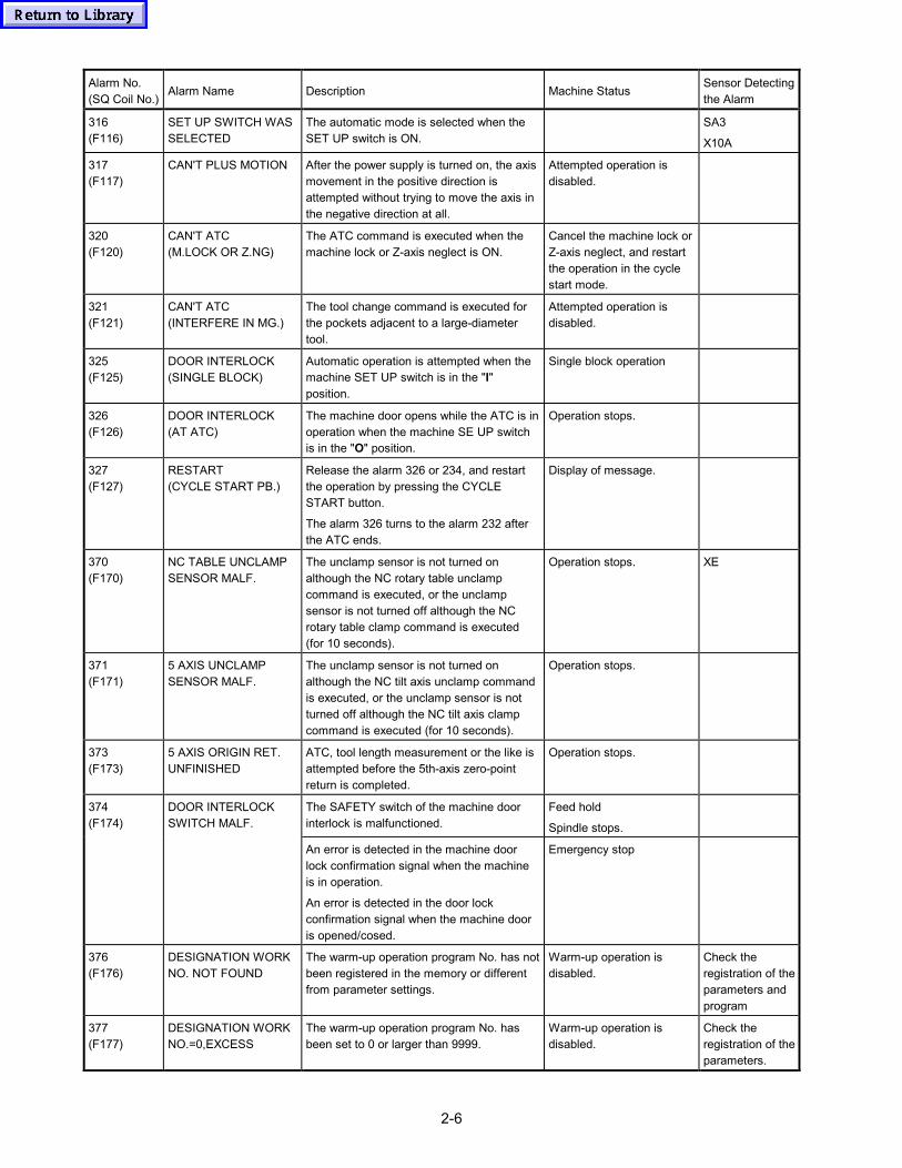
2-6
Alarm No.(SQ Coil No.)
Alarm Name Description Machine StatusSensor Detectingthe Alarm
316(F116)
SET UP SWITCH WASSELECTED
The automatic mode is selected when theSET UP switch is ON.
SA3
X10A
317(F117)
CAN'T PLUS MOTION After the power supply is turned on, the axismovement in the positive direction isattempted without trying to move the axis inthe negative direction at all.
Attempted operation isdisabled.
320(F120)
CAN'T ATC(M.LOCK OR Z.NG)
The ATC command is executed when themachine lock or Z-axis neglect is ON.
Cancel the machine lock orZ-axis neglect, and restartthe operation in the cyclestart mode.
321(F121)
CAN'T ATC(INTERFERE IN MG.)
The tool change command is executed forthe pockets adjacent to a large-diametertool.
Attempted operation isdisabled.
325(F125)
DOOR INTERLOCK(SINGLE BLOCK)
Automatic operation is attempted when themachine SET UP switch is in the "I"position.
Single block operation
326(F126)
DOOR INTERLOCK(AT ATC)
The machine door opens while the ATC is inoperation when the machine SE UP switchis in the "O" position.
Operation stops.
327(F127)
RESTART(CYCLE START PB.)
Release the alarm 326 or 234, and restartthe operation by pressing the CYCLESTART button.
The alarm 326 turns to the alarm 232 afterthe ATC ends.
Display of message.
370(F170)
NC TABLE UNCLAMPSENSOR MALF.
The unclamp sensor is not turned onalthough the NC rotary table unclampcommand is executed, or the unclampsensor is not turned off although the NCrotary table clamp command is executed(for 10 seconds).
Operation stops. XE
371(F171)
5 AXIS UNCLAMPSENSOR MALF.
The unclamp sensor is not turned onalthough the NC tilt axis unclamp commandis executed, or the unclamp sensor is notturned off although the NC tilt axis clampcommand is executed (for 10 seconds).
Operation stops.
373(F173)
5 AXIS ORIGIN RET.UNFINISHED
ATC, tool length measurement or the like isattempted before the 5th-axis zero-pointreturn is completed.
Operation stops.
The SAFETY switch of the machine doorinterlock is malfunctioned.
Feed hold
Spindle stops.
374(F174)
DOOR INTERLOCKSWITCH MALF.
An error is detected in the machine doorlock confirmation signal when the machineis in operation.
An error is detected in the door lockconfirmation signal when the machine dooris opened/cosed.
Emergency stop
376(F176)
DESIGNATION WORKNO. NOT FOUND
The warm-up operation program No. has notbeen registered in the memory or differentfrom parameter settings.
Warm-up operation isdisabled.
Check theregistration of theparameters andprogram
377(F177)
DESIGNATION WORKNO.=0,EXCESS
The warm-up operation program No. hasbeen set to 0 or larger than 9999.
Warm-up operation isdisabled.
Check theregistration of theparameters.
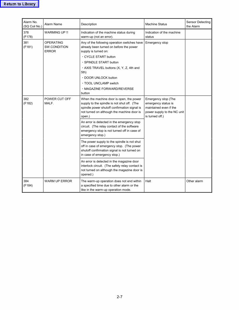
2-7
Alarm No.(SQ Coil No.)
Alarm Name Description Machine StatusSensor Detectingthe Alarm
378(F178)
WARMING UP !! Indication of the machine status duringwarm-up (not an error).
Indication of the machinestatus
381(F181)
OPERATINGSW.CONDITIONERROR
Any of the following operation switches havealready been turned on before the powersupply is turned on:
・CYCLE START button
・SPINDLE START button
・AXIS TRAVEL buttons (X, Y, Z, 4th and5th)
・DOOR UNLOCK button
・TOOL UNCLAMP switch
・MAGAZINE FORWARD/REVERSEbutton
Emergency stop
When the machine door is open, the powersupply to the spindle is not shut off. (Thespindle power shutoff confirmation signal isnot turned on although the machine door isopen.)
An error is detected in the emergency stopcircuit. (The relay contact of the softwareemergency stop is not turned off in case ofemergency stop.)
The power supply to the spindle is not shutoff in case of emergency stop. (The powershutoff confirmation signal is not turned onin case of emergency stop.)
382(F182)
POWER CUT OFFMALF.
An error is detected in the magazine doorinterlock circuit. (The safety relay contact isnot turned on although the magazine door isopened.)
Emergency stop (Theemergency status ismaintained even if thepower supply to the NC unitis turned off.)
384(F184)
WARM UP ERROR The warm-up operation does not end withina specified time due to other alarm or thelike in the warm-up operation mode.
Halt Other alarm

2-8
- MEMO -
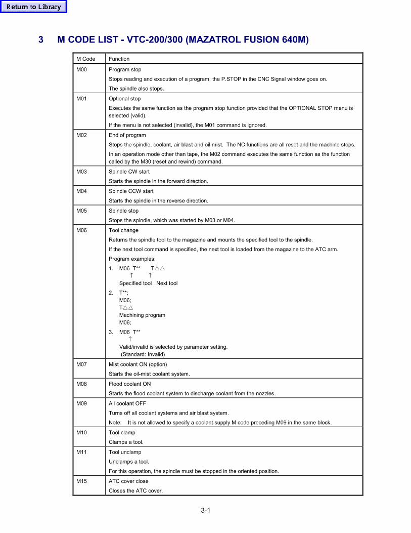
3-1
3 M CODE LIST - VTC-200/300 (MAZATROL FUSION 640M)
M Code Function
M00 Program stop
Stops reading and execution of a program; the P.STOP in the CNC Signal window goes on.
The spindle also stops.
M01 Optional stop
Executes the same function as the program stop function provided that the OPTIONAL STOP menu isselected (valid).
If the menu is not selected (invalid), the M01 command is ignored.
M02 End of program
Stops the spindle, coolant, air blast and oil mist. The NC functions are all reset and the machine stops.
In an operation mode other than tape, the M02 command executes the same function as the functioncalled by the M30 (reset and rewind) command.
M03 Spindle CW start
Starts the spindle in the forward direction.
M04 Spindle CCW start
Starts the spindle in the reverse direction.
M05 Spindle stop
Stops the spindle, which was started by M03 or M04.
M06 Tool change
Returns the spindle tool to the magazine and mounts the specified tool to the spindle.
If the next tool command is specified, the next tool is loaded from the magazine to the ATC arm.
Program examples:
1. M06 T** T△△ ↑ ↑Specified tool Next tool
2. T**;M06;T△△Machining programM06;
3. M06 T** ↑Valid/invalid is selected by parameter setting. (Standard: Invalid)
M07 Mist coolant ON (option)
Starts the oil-mist coolant system.
M08 Flood coolant ON
Starts the flood coolant system to discharge coolant from the nozzles.
M09 All coolant OFF
Turns off all coolant systems and air blast system.
Note: It is not allowed to specify a coolant supply M code preceding M09 in the same block.
M10 Tool clamp
Clamps a tool.
M11 Tool unclamp
Unclamps a tool.
For this operation, the spindle must be stopped in the oriented position.
M15 ATC cover close
Closes the ATC cover.
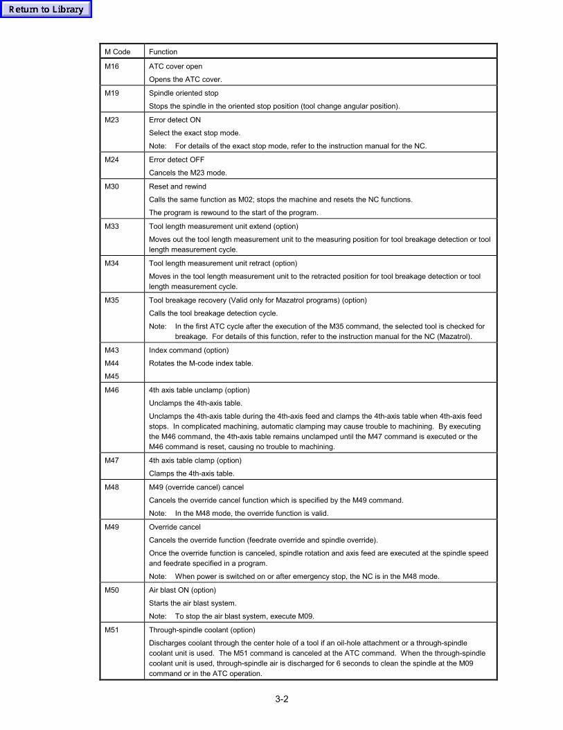
3-2
M Code Function
M16 ATC cover open
Opens the ATC cover.
M19 Spindle oriented stop
Stops the spindle in the oriented stop position (tool change angular position).
M23 Error detect ON
Select the exact stop mode.
Note: For details of the exact stop mode, refer to the instruction manual for the NC.
M24 Error detect OFF
Cancels the M23 mode.
M30 Reset and rewind
Calls the same function as M02; stops the machine and resets the NC functions.
The program is rewound to the start of the program.
M33 Tool length measurement unit extend (option)
Moves out the tool length measurement unit to the measuring position for tool breakage detection or toollength measurement cycle.
M34 Tool length measurement unit retract (option)
Moves in the tool length measurement unit to the retracted position for tool breakage detection or toollength measurement cycle.
M35 Tool breakage recovery (Valid only for Mazatrol programs) (option)
Calls the tool breakage detection cycle.
Note: In the first ATC cycle after the execution of the M35 command, the selected tool is checked forbreakage. For details of this function, refer to the instruction manual for the NC (Mazatrol).
M43
M44
M45
Index command (option)
Rotates the M-code index table.
M46 4th axis table unclamp (option)
Unclamps the 4th-axis table.
Unclamps the 4th-axis table during the 4th-axis feed and clamps the 4th-axis table when 4th-axis feedstops. In complicated machining, automatic clamping may cause trouble to machining. By executingthe M46 command, the 4th-axis table remains unclamped until the M47 command is executed or theM46 command is reset, causing no trouble to machining.
M47 4th axis table clamp (option)
Clamps the 4th-axis table.
M48 M49 (override cancel) cancel
Cancels the override cancel function which is specified by the M49 command.
Note: In the M48 mode, the override function is valid.
M49 Override cancel
Cancels the override function (feedrate override and spindle override).
Once the override function is canceled, spindle rotation and axis feed are executed at the spindle speedand feedrate specified in a program.
Note: When power is switched on or after emergency stop, the NC is in the M48 mode.
M50 Air blast ON (option)
Starts the air blast system.
Note: To stop the air blast system, execute M09.
M51 Through-spindle coolant (option)
Discharges coolant through the center hole of a tool if an oil-hole attachment or a through-spindlecoolant unit is used. The M51 command is canceled at the ATC command. When the through-spindlecoolant unit is used, through-spindle air is discharged for 6 seconds to clean the spindle at the M09command or in the ATC operation.
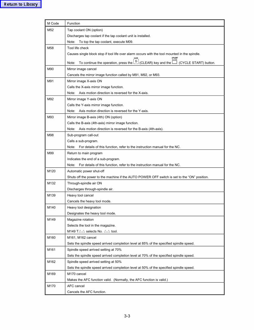
3-3
M Code Function
M52 Tap coolant ON (option)
Discharges tap coolant if the tap coolant unit is installed.
Note: To top the tap coolant, execute M09.
M58 Tool life check
Causes single block stop if tool life over alarm occurs with the tool mounted in the spindle.
Note: To continue the operation, press the (CLEAR) key and the (CYCLE START) button.
M90 Mirror image cancel
Cancels the mirror image function called by M91, M92, or M93.
M91 Mirror image X-axis ON
Calls the X-axis mirror image function.
Note: Axis motion direction is reversed for the X-axis.
M92 Mirror image Y-axis ON
Calls the Y-axis mirror image function.
Note: Axis motion direction is reversed for the Y-axis.
M93 Mirror image B-axis (4th) ON (option)
Calls the B-axis (4th-axis) mirror image function.
Note: Axis motion direction is reversed for the B-axis (4th-axis).
M98 Sub-program call-out
Calls a sub-program.
Note: For details of this function, refer to the instruction manual for the NC.
M99 Return to main program
Indicates the end of a sub-program.
Note: For details of this function, refer to the instruction manual for the NC.
M120 Automatic power shut-off
Shuts off the power to the machine if the AUTO POWER OFF switch is set to the “ON” position.
M132 Through-spindle air ON
Discharges through-spindle air.
M139 Heavy tool cancel
Cancels the heavy tool mode.
M140 Heavy tool designation
Designates the heavy tool mode.
M149 Magazine rotation
Selects the tool in the magazine.
M149 T△△ selects No. △△ tool.
M160 M161, M162 cancel
Sets the spindle speed arrived completion level at 85% of the specified spindle speed.
M161 Spindle speed arrived setting at 70%
Sets the spindle speed arrived completion level at 70% of the specified spindle speed.
M162 Spindle speed arrived setting at 50%
Sets the spindle speed arrived completion level at 50% of the specified spindle speed.
M169 M170 cancel
Makes the AFC function valid. (Normally, the AFC function is valid.)
M170 AFC cancel
Cancels the AFC function.
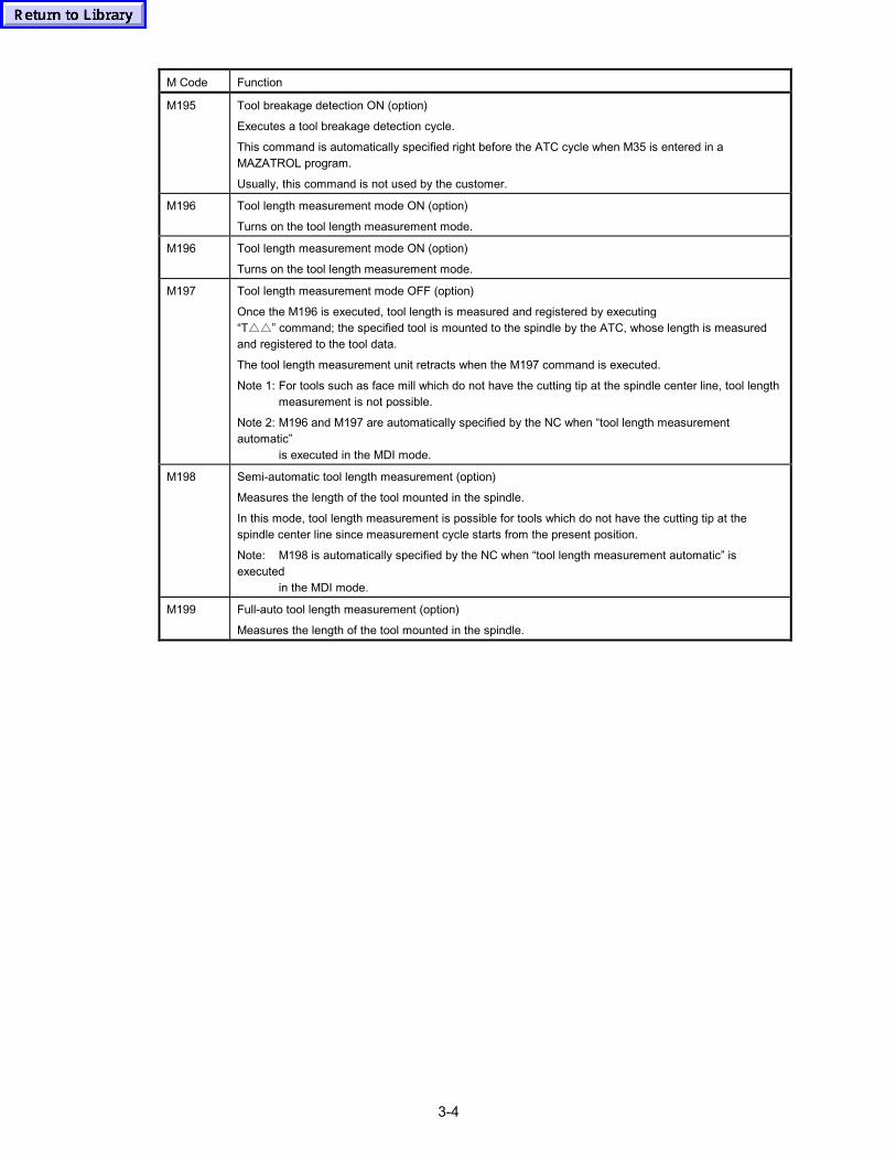
3-4
M Code Function
M195 Tool breakage detection ON (option)
Executes a tool breakage detection cycle.
This command is automatically specified right before the ATC cycle when M35 is entered in aMAZATROL program.
Usually, this command is not used by the customer.
M196 Tool length measurement mode ON (option)
Turns on the tool length measurement mode.
M196 Tool length measurement mode ON (option)
Turns on the tool length measurement mode.
M197 Tool length measurement mode OFF (option)
Once the M196 is executed, tool length is measured and registered by executing“T△△” command; the specified tool is mounted to the spindle by the ATC, whose length is measuredand registered to the tool data.
The tool length measurement unit retracts when the M197 command is executed.
Note 1: For tools such as face mill which do not have the cutting tip at the spindle center line, tool lengthmeasurement is not possible.
Note 2: M196 and M197 are automatically specified by the NC when “tool length measurementautomatic”
is executed in the MDI mode.
M198 Semi-automatic tool length measurement (option)
Measures the length of the tool mounted in the spindle.
In this mode, tool length measurement is possible for tools which do not have the cutting tip at thespindle center line since measurement cycle starts from the present position.
Note: M198 is automatically specified by the NC when “tool length measurement automatic” isexecuted
in the MDI mode.
M199 Full-auto tool length measurement (option)
Measures the length of the tool mounted in the spindle.
3-5
Note 1: Simultaneous processing impossible M codes
Mazatrol permits the entry of up to four M codes in a single block. However, if M codeswhich cannot be processed simultaneously are entered in the same block, the followingmessage is displayed and operation is suspended.
227 SIMULTANEOUS M CODE OPERATION
� This alarm occurs in the following cases:
� Any combination of M03, M04, M05 and M19
� M15 and M16 (opposing operation)
� M23 and M24 (opposing operation)
� M33 and M34 (opposing operation)
� M48 and M49 (opposing operation)
� M06 and M149 (opposing operation)
� M195 to M198, specified with other M code
Note 2: When entering more than one M code in the same block, there is a restriction on entryorder when entering M codes related with coolant and air blast system. An M code starting the coolant system or air blast system must not be entered beforeM09.To enter M08 before M09, for example, enter M08 in a block preceding the M09 block.
M08 M09 M51 → M08M09 M51 ......

3-6
- MEMO -