operating limits expanson - · PDF filePrincipe EXPANSON-V Principe EXPANSON-H ... - a set of...
12
8 6 100 3 800 12 400 1 EXPANSON-V EXPANSON-H bar kW déverseur bâche Principe EXPANSON-V Principe EXPANSON-H EXPANSON 1 •Maintains pressure in closed circuits ex- posed to temperature variations. •Absorbs and compensates the expansion and retraction of the network. •Allows automatic or manual filling of an ins- tallation via a tank, isolating the heating or air-conditioning circuit from the town water supply. For hot water heating circuits (VDI 2035) and chilled-water circuits (up to 40% glycol). - residential and office buildings, - hotels, hospitals, clinics, - shopping centres, shops, - schools, universities, barracks. OPERATING LIMITS Temperature range : +5° à +90°C Max. ambient temperature : +50°C EXPANSON-H EXPANSON-V Operating pressure to be maintained : ≤ 6 bar ≤ 8 bar Total installed load : 3 800 kW 12 400 kW Nbr. of pumps: 1 - 2 2 Pipe ND : G1 tapped G1 1/2 threaded G1 1/2 threaded APPLICATIONS EXPANSION SETS Hot water - Chilled water 50 Hz N.T. N° 127-2/ENG. - Éd.4/04-08 • ExPANsON-h one-pump version mounted on tank • ExPANsON-V version with electronic control box (separate storage tank) tank discharge device 1 standby pump 1 pump On 1 standby pump tank discharge device
-
Upload
hoangduong -
Category
Documents
-
view
222 -
download
2
Transcript of operating limits expanson - · PDF filePrincipe EXPANSON-V Principe EXPANSON-H ... - a set of...

8
6
100 3 800 12 4001
EXPANSON-VEXPANSON-Hbar
kW
déverseur bâche
1 pompe de maintien1 pompe de secours
déverseur bâche
1 pompe de maintien
Principe EXPANSON-V Principe EXPANSON-H
expanson
1
• Maintains pressure in closed circuits ex-posed to temperature variations.• Absorbs and compensates the expansion and retraction of the network.• Allows automatic or manual filling of an ins-tallation via a tank, isolating the heating or air-conditioning circuit from the town water supply.
For hot water heating circuits (VDI 2035) and chilled-water circuits (up to 40% glycol).- residential and office buildings,- hotels, hospitals, clinics,- shopping centres, shops,- schools, universities, barracks.
operating limitsTemperature range : +5° à +90°C
Max. ambient temperature : +50°C
expanson-h expanson-v
Operating pressure to be maintained :
≤ 6 bar ≤ 8 bar
Total installed load : 3 800 kW 12 400 kW
Nbr. of pumps : 1 - 2 2
Pipe ND : G1 tappedg11/2 threaded
g11/2 threaded
appliCations
expansIon seTsHot water - Chilled water
50 Hz
N.T. N° 127-2/ENG. - Éd.4/04-08
• ExPANsON-h one-pump version mounted on tank
• ExPANsON-V version with electronic control box (separate storage tank)
tankdischarge device
1 standby pump1 pump On1 standby pump
tankdischarge device

expanson
2
Design oF the expanson-hPressure maintenance system using pump(s) and an adjustable discharge device.• expanson-h, two-pump version• Set with :- two horizontal multi-stage pumps connected to tank by galvanized cast-iron pipe.- A standby pump is available.• expanson-h, one-pump version• Set with :- one horizontal multi-stage pump connected directly to tank.• Both versions have :- an electronic regulation box (CE), with automatic change of pump starting order in twopump version,- an adjustable discharge device with filter,- a set of isolating valves and one check valve per pump,- one set isolating valve (one-pump version), - one control pressure switch and two safety pressure switches.The assembly is mounted on a base andconnected to a galvanized steel tank (200 to1,500 liters).
Design oF the expanson-v
Pressure maintenance system using a pump and an adjustable discharge device.• Set with :- two vertical multi-stage pumps (one on stan-dby) for reinjection of water into the network,- an adjustable discharge device to let the ex-panded volume leak to the tank (with protec-ting filter),- a regulation box, available in 3 versions : CE = electronic CM = electromechanical CV = speed controller- two galvanized cast-iron pipes,- one set of suction and discharge valves per pump,- one quiet check valve per pump,- one pressure switch for automatic control of pumps (CE and CM),- one pressure transmitter (CV),- two safety pressure switches,- one permanent automatic pump degassing system.• One open galvanized steel tank, 200 to 5,000 liters, with automatic filling. The set and tank are mounted on separate bases.
aDvantages oF the expanson-h set• Compact, light-weight monobloc assembly.
• Economical set, easy to install.• Operation fully automatic.• Assembly factory-installed on tank with transport base.
aDvantages oF the expanson-v set• Compact sets take little floor space.• Adjustments grouped on front and easy to make.
• Operation fully automatic.• Operating safety: fault reporting; shut-ting off of lights; permanent availability of a standby pump.
• Automatic filling with isolation between the heating or air-conditioning circuit and the town water supply.
• Adjustments grouped on front and easy to make.
• Complete isolation between the heating circuit and the town water supply.
• Permanent degassing of mechanical seals.
• Pump made of stainless steel, pipes and tanks galvanized.
• Automatic filling of tank under water line.
iDentiFiCation
expanson-h-206-1-M-600-ExPANsION application code
Type of horizontal multi-stage pump used in the set
Number of pumps : 1 or 2
Power supply :(M = single-phase, T = 3-phase)
Capacity of storage tank (in liters)
Codes of optional accessories (indicate if ordered)
iDentiFiCation expanson-v-206-CE-T-
ExPANsION application code
Type of vertical multi-stage pump used in the set
Control :CM : electromechanical boxCE : electronic boxCV : speed controller box
Power supply :(M = single-phase, T = 3-phase)
Codes of optional accessories (indicate if ordered)
m (sleeves)CB (counter-flanges)2D (2nd discharge device)aB (anti-hammer)F (pulse-type cap-tor - allows leak detection)
v (set isolating valve for 2-pump version)
m (sleeves)CB (counter-flanges)2D (2nd discharge device)aB (anti-hammer)F (pulse-type cap-tor - allows leak detection)
v (set isolating valve for 2-pump version)

7
7
11
12
Ød
4
5
83
3a3b
15
12
13
14
9
10b10a
6
Øa
Øc
Øb
6
5
7
4
2
32b
10
17
8
9
10
16
2a12b
12a
13
1
11
18
19
14
15
L
L1
H3
H2
1"
1/2"
1"
expanson
3
DesCription oF the expanson-h
DesCription oF the expanson-v
01 - Control and automation box (electronic). 02 - Tank (200, 400, 600, 800, 1 000 ou
1 500 liters depending on model). 03 - horizontal multi-stage pump(s). 03a - Filling plug. 03b - Drain plug. 04 - Discharge device. 05 - Filter with protecting strainer. 06 - Pressure gauge.
07 - set isolating valve (one-pump version only). 08 - Check valve. 09 - Control pressure switch. 10a - Low pressure safety switch. 10b - high pressure safety switch. 11 - Filling control float switch. 12 - Dry-running float switch. 13 - Electrovalve. 14 - Town water isolating valve.
15 - Pump suction isolating valve. Øa - Installation connection port (Ø1” tapped, in 1-pump version - Ø1”1/2 threaded in 2-pump version). Øb - Tapped filling port (Ø1/2”). Øc - Tapped discharge device port (Ø1”). Ød - Tapped drain port (Ø1”).
Version shown: electromechanical control box01 - Control and automation box (electromechanical,
electronic, or speed controller box). 02 - Two Multi-V vertical multi-stage pumps. 02a - Filling plug. 02b - Drain plug. 03 - suction pipe. 04 - Pump suction isolating valve. 05 - Discharge pipe. 06 - Pump discharge isolating valve. 07 - Check valve. 08 - Discharge device. 09 - Filter with protecting strainer. 10 - Discharge device isolating valves. 11 - Control pressure switch (CE, CM versions). 12a - high pressure safety switch. 12b - Low pressure safety switch. 13 - Pressure gauge. 14 - Electrovalve. 15 - Town water isolating valve Ø1/2”. 16 - Permanent automatic pump degassing device. 17 - Discharge device adjustment plug. Not shown: pressure captor and lifting rings (CV version). TANK (200 à 5 000 liters) : 18 - Filling control float. 19 - Dry-running float switch.(Livré raccordé
au coffret avec 5 m de câble).

Puissanceutile inst.
à 90ϒC
à 110ϒC
m - bar à maintenir70 - 8
60 - 7
50 - 6
35 - 4,5
25 - 3,5
15 - 2,5
EXPANSON - H
H206-1206-2
H206-1206-2
H205-1205-2
H205-1205-2
H204-1204-2
H204-1204-2
H203-1203-2
H203-1203-2
Nous
consulter
476 1045 1392 1857 2357 3807 5250 5991 7574 8592 9822 12473
5,8 12,5 17 22 28 45 63 72 91 103 118 150
4 8,8 11,7 15,6 20 32 44 50 64 72 82 105m
m
kW
Bâche 200 400 600 800 1000 1500 2000 2500 3000 3500 4000 5000 l
3
3Si installation :
Puissanceutile inst.
à 90ϒC
à 110ϒC
m - bar à maintenir70 - 8
60 - 7
50 - 6
35 - 4,5
25 - 3,5
15 - 2,5
EXPANSON - V
V206
V208
V207
V205
V204
V203
V206
V208
V207
V205
V204
V203
476 1045 1392 1857 2357 3807 5250 5991 7574 8592 9822 12473
5,8 12,5 17 22 28 45 63 72 91 103 118 150
4 8,8 11,7 15,6 20 32 44 50 64 72 82 105m
m
kW
Bâche 200 400 600 800 1000 1500 2000 2500 3000 3500 4000 5000 l
3
3Si installation :
expanson
4
rapiD seleCtion oF expansion sets PRELIM. CALCULATIONSTheoretical volume of installation
Conversion of kW/h into liters
Heating element alone per 1 kW/h
for installations
steel convectors 7 liters
≤ 500 kWsteel radiators 7 litersCast iron radiators 10 litersheating plates 9 litersAll heating elements 7 liters > 500 kW
If the volume of the installation is not known, calculate on the assumption of 12 litres per kW useful power.
Example opposite : pressure to be maintained = 4 bars and,installation power = 1600 kW, choose:- ExPANsON-h- 205 set with 1 or 2 pumps- with 800 liters tank.
HOT-WATER CIRCUITExpansion volume :Vexp = Vt x (Cm – Cr)where :vt : is the total volume of the installationCm : is the coefficient of expansion at the
mean operating temperature, i.e. :boiler outlet T° + return T°
2
Cr : is the coefficient of expansion at the filling temperature (10° to 12°C)
Example opposite : static head = 55 metres and,volume of installation = 80 m3 (at 90°C), choose :- ExPANsON-V-207-CE-T- with 3000 liters tank.
to maintain
atat
atat
to maintain
tank
tank
Consult us
Installed load
Installed load
if installation
if installation

6
100 3 8001
bar
kW
8
6
100 3 800 12 4001
bar
kW
expanson
5
operating prinCiple
a) HeatingWhen the burner starts (heating system) or the cooler stops (air-conditioning system), the temperature in the circuit increases and with it the pressure.When the pressure exceeds the discharge device setting, the discharge device opens and lets the excess expanded water leak back to the storage tank (expansion stage) until the pressure falls back to its setting.
b) CoolingWhen the burner stops (heating system) or the cooling unit starts (air-conditioning sys-tem), the temperature of the liquid falls and the static pressure decreases (contraction phase).When the pressure reaches the minimum that must be maintained in the installation, the control pressure switch starts the pump. The pump draws water from the storage tank and discharges into the circuit to raise the pressure to the pump stopping value.When the pressure in the installation is steady, neither the discharge device nor the pump operate.
DETERMINATION OF ADJUSTMENTSpression de tarage dessoupapes de sécuritéalarme pressiontrop forte
alarme pressiontrop faible
ouverture maxi du déverseur
arrêt pompe
pompe
déverseur
variation dela pressiondansl'intallation (3)
PRESSIONMINI(2)
PRESSIONMAXIDANSL'INSTALLATION
garde de sécurité(5 à 10 m de CE)
tension de vapeur (s'il y a lieu){{
HAUTEUR STATIQUE(1)
(1) : Hauteur statique au point le plus élevé de l'installation. Valeur à utiliser pour entrer dans le tableau de sélection par l'échelle des hauteurs.(2) : Pression mini à maintenir par le module. Valeur à utiliser pour entrer dans le tableau de sélection par l'échelle des pressions.(3) : Correspond au différentiel du module, soit 0,8 à 1 bar.
mise en route pompe . . . .
. . . . . .
COFFRETELECTRONIQUE1-2 POMPES
COFFRETELECTROMECANIQUE2 POMPES
COFFRETELECTRONIQUE2 POMPES
COFFRETVARIATION DE VITESSE2 POMPES
Bâches séparées :200à 5 000 litres
Montés sur bâches :200à 1 500 litres
stoppage of pump
safety allowance(5 to 10 m w.g.)
Vapour pressure (if applicable)
eleCtroniCBox1 OR 2 PUMPS
Installed on tanks:200 to 1,500 liters
Separate tanks:200to5,000 liters
eleCtroniCBox2 PUMPS
eleCtro- meChaniCalBox2 PUMPSspeeD ControllerBox2 PUMPS
MAX.PRESSUREininstallation
sTATIC hEIGhT
MIN.PREssURE
Discharge device
pump
Pressurevariation ininstallation
high pressure alarm
Low pressure alarm
safety valve pressure setting
Max. discharge deviceopening
starting of pump
static height to highest point in installation. Value to use for entry intothe selection table by height scale.Min. pressure the module must maintain. Value to use for entry intothe selection table by pressure scale.Corresponds to the differential of the module, 0.8 to 1 bar.

expanson
6
SUPPLIESstanDarD- Pump isolating valves,- set isolating valve ( ExPANsON-h - 1 pump),- Check valve,- Discharge device with protecting filter,- Pressure gauge,- Dry-running and filling floats,- Filling electrovalve.
optional- set isolating valves ( ExPANsON-h - 2 pumps / ExPANsON-V),- Anti-vibration sleeves,- Counter-flanges,- Anti-hammer reservoir,- Pulse meter,- 2nd discharge device.
installation prinCiple expanson-h —1 pump
expanson-v Electromechanical control box

1
10 10 3 3 8 6
5 5 9 24
12345
9
6
8
7
8
expanson
7
ELECTRONIC CONTROL BOX: DESCRIPTION AND OPERATIONBox in conformity with standards in force.sealed, IP 55 protection.Functions - Motor protection by electronic thermal relays,- Automatic starting and stopping of pumps according to minimum pressure to be maintained.- Change of starting order (2-pump version).Power supply 3-phase: 230/400 v - (50hz)1-phase (optional) : 230 v - (50hz)
Description: 2-pump versionOn front panel Rotary safety and power switch control strip with :
1 Power On indicator2 Dry Running indicator3 Low Pressure indicator4 high Pressure indicator5 Filling On indicator6 On indicator for each pump7 Fault indicator for each pump8 Three-way switch for each pump : auto - o
- manu (non-latching)9 “ Electrovalve opening switch : auto - manu
(latching)
Inside 1 General disconnecting switch with line
power connecting terminals2 12V transformer supplying controls3 Contactor (1 per pump) with motor connec-
ting terminals4 Terminal block for external units (pressure
switch, float switch, fault reporting)5 Thermal relay with sliding motor current
adjustment contact6 Connectors for power supply jack of auto-
mation board
7 Automation and display board8 Voltage selection switch (230 or 400 V)9 selector for Low pressure fault operating
mode : a- pump stops on fault / b : pump stays running on fault
10 Motor protection fuses
Operation: 2-pump versionPrinciple The operation of the set is automated by one control pressure switch and two safety pres-sure switches (Low and high pressures).The other pump is on standby.When the control pressure switch closes at its low pressure setting, the pump starts. When the control pressure switch opens at its high pressure setting, the pump stops.At each cycle, the pump starting order is changed.
When a pump fault is detected, the standby pump is started immediately.If the switch of the pump that is to be started is set to O (off), the set automatically changes over to the other pump.In manual operation, with the switch held in the non-latching MANU position, the two pumps can operate simultaneously.Filling In the automatic mode, the electrovalve ope-ning switch responds to a contact closure (float switch) and fills the installation.Filling can also be controlled manually–set the switch to MANU (latching position).saFetY At high pressure, the pump in operation stops.At Low pressure, there is a choice of modes,- switch set to A, the pump stops (to eliminate the risk of flooding if there is a leak);- switch set to B, the pump continues to run (to eliminate the risk of vaporization once the risk of a leak has been neutralized).Dry running, detected by the float in the tank, stops the pump.DTU 65-11 requires the cutting off of the lights in the three cases mentioned above. An NC dry contact is provided for this.FAULT REPORTING There are NO dry contacts for :- general fault,- dry running,- individual pump fault,- low pressure, and - high pressure.
Operation: 1-pump versionIn the case of a 1-pump ExPANsON-h - theelectronic box has only one power line.The automation board is adapted to operation without a standby pump, with only general fault reporting (NO contact).The cutting off of the lights (NC contact) is still mandatory.

46
2
3
5
2 3 5 4 7
6
expanson
8
speeD Controller BoxBox in conformity with standards in force.sealed, IP 559 protection.Functions - Motor protection by magneto-thermal circuitbreakers,- Automatic starting and stopping of pumps according to minimum pressure to be maintained.- Change of pump starting order.Power supply Three-phase : 230/400 V - (50hz)DesCription On front panel Lockable outside safety and power discon-necting switch; closing by key lock; control strip with :1 Power On light2 Dry Running light3 Low Pressure light4 high Pressure light5 Filling On light6 On light for each pump7 Fault light for each pump (ALARM)8 Controlled-pump Fault light9 speed controller Fault light10 Controlled-pump Fault reset11 speed controller Fault reset12 speed controller ON-OFF switch
13 Three-way switch for each pump: AUTO O-MANU (non-latching)
14 Electrovalve opening switch: AUTO-MANU (latching)
Inside 1 General disconnecting switch with line
power connecting terminals2 24V transformer supplying controls3 Contactor (1 per pump) with motor connec-
ting terminals4 Terminal block for external units (pressure
switch, float switch, fault reporting)5 Thermal circuit-breaker with sliding mo-
torcurrent adjustment contact and reset pushbutton for fixed pump
6 speed controller7 selector for Low pressure fault operating
mode :• with jumper: pump stops on fault• without jumper: pump stays running on fault.
operation The pressure transmitter records the pressure in the network and sends signals to the speed controller (frequency converter).
eleCtromeChaniCal Control BoxBox in conformity with standards in force.sealed, IP 559 protection.Functions - Motor protection by magneto-thermal circuitbreakers,- Automatic starting and stopping of pumps according to minimum pressure to be maintained.- Change of pump starting order.Alimentation 3-phase : 230/400 V - (50hz)1-phase (optional) : 230 V - (50hz)DesCription On front panel Outside safety and set power disconnectingswitch; closing by key lock; control strip with :1 Power On light2 Dry Running light3 Low Pressure light4 high Pressure light5 Filling On light6 On light for each pump7 Fault light for each pump
8 Three-way switch for each pump: AUTO - O - MANU (non-latching)
9 Electrovalve opening switch: AUTO - MANU (latching)
Inside 1 General disconnecting switch with line
power connecting terminals2 24V transformer supplying controls3 Contactor (1 per pump) with motor connec-
ting terminals4 Terminal block for external units (pressure
switch, float switch, fault reporting)5 Thermal circuit-breakers with sliding
motor current adjustment contact and reset pushbutton
6 selector for Low pressure fault operating mode :
• with jumper: pump stops on fault• without jumper: pump stays running on fault.
operation The operation of the set is automated by onecontrol pressure switch and two safety pres-sure switches. LThe operating principle is the same as that of the electronic control box.
If the pressure falls below the set-point, the controller increases the speed of the controlled pump. When the pressure reaches or exceeds the setpoint, the controller decreases the speed of the pump.
When the pressure in the network is steady and the controller is at minimum speed, the pump is stopped after a delay.

14
15
L
L1
H3
H21"
1/2"
1"
1"
ØD
H
PP1
P2P3
H1
L
H3
H2
1"1/2
1"
1/2"
expanson
9
eleCtriCal Data anD Dimensions oF expanson-h
Reference : expanson-h 203 to 206Numbers of
pumps 1 1 1 2 1 2
Tank Capacity ØD h l l1 p p h1 h2 h3 p1 p1 p2 p3liters mm mm mm mm mm mm mm mm mm mm mm mm mm200 500 1300 610 150 1200 1250 500 960 1010 920 950 510 300400 600 1700 770 150 1300 1350 500 1460 1510 1020 1050 600 350600 700 1700 870 150 1400 1450 500 1460 1510 1120 1150 700 400800 800 1700 970 150 1500 1550 500 1460 1510 1220 1250 770 4501000 900 1700 1070 150 1600 1650 500 1460 1510 1320 1350 870 5001500 1250 1350 1420 150 1950 2000 500 1010 1060 1670 1700 1100 675
Set Reference Number and type of pump
Total installed
motor power p2
Max. current
3-phase 400V 1-phase 230VkW A A
ExPANsON-h 203-(1 or 2)-M-* 1 or 2 Multi-h 203M 1 or 2x 0,55 - 1 or 2x4 ExPANsON-h 203-(1 or 2)-T-* 1 or 2 Multi-h 203T 1 or 2x0,55 1 or 2x1,7 - ExPANsON-h 204-(1 or 2)-M-* 1 or 2 Multi-h 204M 1 or 2x0,55 - 1 or 2x4 ExPANsON-h 204-(1 or 2)-T-* 1 or 2 Multi-h 204T 1 or 2x0,55 1 or 2x1,7 - ExPANsON-h 205-(1 or 2)-M-* 1 or 2 Multi-h 205M 1 or 2x0,75 - 1 or 2x5,1 ExPANsON-h 205-(1 or 2)-T-* 1 or 2 Multi-h 205T 1 or 2x0,75 1 or 2x2 - ExPANsON-h 206-(1 or 2)-M-* 1 or 2 Multi-h 206M 1 or 2x1,1 - 1 or 2x6,8 ExPANsON-h 206-(1 or 2)-T-* 1 or 2 Multi-h 206T 1 or 2x1,1 1 or 2x2,8 -*Tank capacity : 200, 400, 600, 800, 1000 or 1500 liters

750
540
550
220
150
30
1080
450
470
100
50
A
H
D
C
G
B
E
F
90
H
600
450
300
190
100
L
ØD
P
A
H
D
C
G
B
E
F
90
H
600
450
300
190
100
L
ØD
P
expanson
10
eleCtriCal Data anD Dimensions oF expanson-v
Set reference Number and type of pumps
Total installed motor power P2
Max. current 400V 3-phase
kW A ExPANsON-V 203-CE or -CM or -CV 2 Multi-V 203T 2 x 0,55 2 x 1,35 ExPANsON-V 204-CE or -CM or -CV 2 Multi-V 204T 2 x 0,75 2 x 1,7 ExPANsON-V 205-CE or -CM or -CV 2 Multi-V 205T 2 x 0,75 2 x 1,7 ExPANsON-V 206-CE or -CM or -CV 2 Multi-V 206T 2 x 1,1 2 x 2,4 ExPANsON-V 207-CE or -CM or -CV 2 Multi-V 207T 2 x 1,1 2 x 2,4 ExPANsON-V 208-CE or -CM or -CV 2 Multi-V 208T 2 x 1,5 2 x 3,2
•Electronic control box versionConnected by 1 1/2” threaded pipes on either left or right side
Storage tank
Capacity ØD p h lliters mm mm mm mm200 500 600 1200 540400 600 700 1600 700600 700 800 1600 800800 800 900 1600 9001000 900 1000 1600 10001500 1250 1350 1250 13502000 1250 1350 1800 13502500 1250 1350 2000 13503000 1500 1600 1800 16003500 1500 1600 2000 16004000 1600 1700 2000 17005000 1800 1900 2000 1900
A = suction port 1”1/2 GB = Discharge device connection 1”1/2 GC = Filling float 1”1/4 GD = Dry-running float 1”1/4 GE = Discharge device port 1” GF = Electrovalve connection 1/2” GG = Drain port 1” Gh = Degassing port 1/4”G
750
540
550
220
150
30
1350
450
470
100
750
540
550
220
150
301350
450
470
100
750
550
110
1670
450
500
65
750
550
110
1670
450
500
65
expanson
11
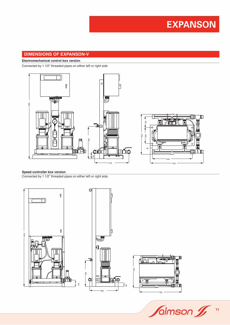
Dimensions oF expanson-v Electromechanical control box versionConnected by 1 1/2” threaded pipes on either left or right side
Speed controller box versionConnected by 1 1/2” threaded pipes on either left or right side.

expanson
12
FEATURESa) Electrical- 3-phase, 230/400V, 50 hz, without neutral, - single-phase, 230V optional (specify with order).- All controls are connected at the factory.- To be done: connection to line power, fault reporting, and cutoff of lights (as per DTU 65-11).
b) Installation- On stable horizontal surface.- hydraulic connections to be made :- Town water supply.- Tank discharge device and drain.- set to installation return.- set and pump degassing to tank (ExPANsON-V).- Level floats to tank (Version V)
c) Packaging- set under cover on pallet.- separate tank for ExPANsON-V set.
d) Maintenance- Replacement or repair of component ack-nowledged defective on the set.- Recommended spare parts for pump(s).
options- set isolating valves,- Anti-vibration sleeves in pipe diameters,- Counter-flanges in pipe diameters,- Anti-hammer reservoir,- Pulse-type water meter.- 2nd discharge device, connnected to right or left side of set ( ExPANsON-V).
stanDarDsCompliance with the following standards :• DTU 65-11, which requires cutting off the lights in the event of :- dry running,- low pressure,- high pressure.• NFC 15-100 on low-voltage electrical installations.• EN 60-204 on the safety of machines.• CEM EN 61000-6-1 and 6-2, • CEM EN 61000-6-3 and 6-4,• EC declaration: “machines” directive.
speCiFiCations oF Components oF setsPump(s)- Cent r i fuga l , mul t i - s tage, ver t i ca l (ExPANsON-V or horizontal (ExPANsON-h), all stainless steel.- Mechanical seals,- 230/400V, three-phase, 50 hz motors.- single-phase motor optional in version V.- Insulation class 155 (F).- Protection index at least IP 54.
Control boxessee descriptions on preceding pages.
Discharge device- Check valve spring and seat of stainless steel.- Body and valve of brass.- Tapped holes, ø 1”.- MDPE adjustment membrane.- KVs coefficient: 5.The discharge device assembly has a leakcontrol plug to optimize the opening pressure adjustment.
Discharge device protection filter- Brass housing.- Tapped holes ø 1”.- stainless steel strainer can be removed quic-kly for cleaning.
Pump control pressure switch- With glycerin-bath pressure gauge. Contact closes when pressure falls.- Differential adjustable from 0.5 to 1 bar.
Safety pressure switchesThere are two safety pressure switches on the discharge pipe :• high pressure: stops pump. Fault reporting (NO contact) and cutting off of lights (NC contact).• Low pressure: fault reporting NO contact) and cutting off of lights NC contact).
Notea jumper inside the control box givesa choice of two operating modes when there is a Low pressure fault :A) stopping the pump so there will be no
risk of flooding if there is a leak in the installation.
B) Keeping the pump running to forestall the risk of vaporization in the installa-tion if the risk of a leak can be ruled out, by a pulsetype meter, for instance.
Suction and discharge pipes (2 pumps set) Made of galvanized cast iron, 1 1/2” (40-49), threaded.
Storage tankVertical, made of galvanized steel, with :• 2 level regulators (filling and dry-running), factory-wired to the control box, to be instal-led on the tank ports.
• 1 filling electrovalve, factory-wired to the control box, to be installed on the tank.
Notea splined coupling provided with the tank can be installed in place of the electrovalve for direct filling with town water when the installation is first filled.
• 1 discharge device port and 1 drain port, on the same plane to facilitate connecting to a drain.• 1 port for connection of permanent de-gassing of mechanical seals (version V), with adjustment valve to avoid any risk in the event of a prolonged shutdown of the pumps.• A sheet-metal lif ting chassis for transport.
Notethe tank is filled under the water line to avoid agitation and oxygenation of the water while maintaining isolation from the town water supply.
• ExPANsON-h (1 or 2 pumps) : tanks from 200 to 1,500 liters, on the set.• ExPANsON-V (2 pumps) : tanks from 200 to 5,000 liters, separate from the set.
• Level regulators (filling and dry running) and filling electrovalve for storage tank