Operating Instructions Waterpilot FMX21 -...
84
Products Solutions Services BA00380P/00/EN/14.13 71205221 Valid from software version: 01.00.zz Operating Instructions Waterpilot FMX21 Hydrostatic level measurement
Transcript of Operating Instructions Waterpilot FMX21 -...

Products Solutions ServicesBA00380P/00/EN/14.1371205221
Valid from software version:01.00.zz
Operating InstructionsWaterpilot FMX21Hydrostatic level measurement
Waterpilot FMX21
2 Endress+Hauser
Table of contents
1 About this document . . . . . . . . . . . . . . . 3
1.1 Symbols . . . . . . . . . . . . . . . . . . . . . . . . . . . . . . . . . . . 31.2 Registered trademarks . . . . . . . . . . . . . . . . . . . . . . . 4
2 Basic safety instructions . . . . . . . . . . . . 5
2.1 Designated use . . . . . . . . . . . . . . . . . . . . . . . . . . . . . 52.2 Installation, commissioning and operation . . . . . . 52.3 Operational safety and process safety . . . . . . . . . . 5
3 Incoming acceptance and product
identification . . . . . . . . . . . . . . . . . . . . . . 6
3.1 Incoming acceptance . . . . . . . . . . . . . . . . . . . . . . . . 63.2 Product identification . . . . . . . . . . . . . . . . . . . . . . . . 63.3 Transport and storage . . . . . . . . . . . . . . . . . . . . . . . 83.4 Scope of delivery . . . . . . . . . . . . . . . . . . . . . . . . . . . . 83.5 CE mark, Declaration of Conformity . . . . . . . . . . . . 8
4 Mounting . . . . . . . . . . . . . . . . . . . . . . . . . 9
4.1 Mounting requierements . . . . . . . . . . . . . . . . . . . . . 94.2 Mounting the Waterpilot with a mounting
clamp . . . . . . . . . . . . . . . . . . . . . . . . . . . . . . . . . . . 104.3 Mounting with an extension cable mounting
screw . . . . . . . . . . . . . . . . . . . . . . . . . . . . . . . . . . . . 114.4 Mounting the terminal box . . . . . . . . . . . . . . . . . 124.5 Mounting the TMT182 temperature head
transmitter . . . . . . . . . . . . . . . . . . . . . . . . . . . . . . 124.6 Mounting the terminal strip for the Pt100 passive
(without TMT182) . . . . . . . . . . . . . . . . . . . . . . . . 134.7 Post-mounting check . . . . . . . . . . . . . . . . . . . . . . 13
5 Electrical connection. . . . . . . . . . . . . . . 14
5.1 Connecting the device . . . . . . . . . . . . . . . . . . . . . 145.2 Connecting the measuring unit . . . . . . . . . . . . . . 185.3 Post-connection check . . . . . . . . . . . . . . . . . . . . . 22
6 Operability . . . . . . . . . . . . . . . . . . . . . . . 22
6.1 Overview of operation options . . . . . . . . . . . . . . 22
7 Commissioning . . . . . . . . . . . . . . . . . . . 24
7.1 Function check . . . . . . . . . . . . . . . . . . . . . . . . . . . 247.2 Commissioning with FieldCare . . . . . . . . . . . . . . 247.3 Pressure measurement . . . . . . . . . . . . . . . . . . . . . 277.4 Level measurement . . . . . . . . . . . . . . . . . . . . . . . . 297.5 Linearization . . . . . . . . . . . . . . . . . . . . . . . . . . . . . 44
8 Troubleshooting . . . . . . . . . . . . . . . . . . 48
8.1 Messages . . . . . . . . . . . . . . . . . . . . . . . . . . . . . . . . 488.2 Malfunctions of Waterpilot FMX21 with optional
Pt100 . . . . . . . . . . . . . . . . . . . . . . . . . . . . . . . . . . . 508.3 Malfunctions of TMT182 temperature head
transmitter . . . . . . . . . . . . . . . . . . . . . . . . . . . . . . . 51
8.4 Firmware history . . . . . . . . . . . . . . . . . . . . . . . . . . 51
9 Maintenance . . . . . . . . . . . . . . . . . . . . . .51
9.1 Exterior cleaning . . . . . . . . . . . . . . . . . . . . . . . . . . . 51
10 Repair . . . . . . . . . . . . . . . . . . . . . . . . . . . .52
10.1 Spare parts . . . . . . . . . . . . . . . . . . . . . . . . . . . . . . . . 5210.2 Return . . . . . . . . . . . . . . . . . . . . . . . . . . . . . . . . . . . 5210.3 Disposal . . . . . . . . . . . . . . . . . . . . . . . . . . . . . . . . . . 52
11 Accessories . . . . . . . . . . . . . . . . . . . . . . .52
11.1 Mounting clamp . . . . . . . . . . . . . . . . . . . . . . . . . . . 5211.2 Terminal box . . . . . . . . . . . . . . . . . . . . . . . . . . . . . . 5211.3 Additional weight for Waterpilot with outer
diameter of 22 mm (0.87 in) and 29 mm (1.14 in) . . . . . . . . . . . . . . . . . . . . . . . . . . . . . . . . . . 53
11.4 TMT182 temperature head transmitter(4 to 20 mA HART) . . . . . . . . . . . . . . . . . . . . . . . . 53
11.5 Extension cable mounting screw . . . . . . . . . . . . . 5311.6 Terminals . . . . . . . . . . . . . . . . . . . . . . . . . . . . . . . . . 5411.7 Cable marking . . . . . . . . . . . . . . . . . . . . . . . . . . . . . 5411.8 Cable shortening kit . . . . . . . . . . . . . . . . . . . . . . . . 5411.9 Testing adapter for FMX21 with outer diameter of
22 mm (0.87 in) and outer diameter of 29 mm (1.14 in) . . . . . . . . . . . . . . . . . . . . . . . . . . . . . . . . . . 55
12 Technical data. . . . . . . . . . . . . . . . . . . . .55
13 Appendix . . . . . . . . . . . . . . . . . . . . . . . . .56
13.1 Overview of the operating menu . . . . . . . . . . . . . 5613.2 Description of parameters . . . . . . . . . . . . . . . . . . . 64
Index. . . . . . . . . . . . . . . . . . . . . . . . . . . . .81
Waterpilot FMX21 About this document
Endress+Hauser 3
1 About this document
1.1 Symbols
1.1.1 Safety symbols
1.1.2 Electrical symbols
1.1.3 Symbols for certain types of information
Symbol Meaning
A0011189-DE
DANGER!This symbol alerts you to a dangerous situation. Failure to avoid this situation will result in seriousor fatal injury.
A0011190-DE
WARNING!This symbol alerts you to a dangerous situation. Failure to avoid this situation can result in seriousor fatal injury.
A0011191-DE
CAUTION!This symbol alerts you to a dangerous situation. Failure to avoid this situation can result in minoror medium injury.
A0011192-DE
NOTICE!This symbol contains information on procedures and other facts which do not result in per-sonalinjury.
Symbol Meaning
A0018335
Direct currentA terminal to which DC voltage is applied or through which direct current flows.
A0018336
Alternating currrentA terminal to which alternating voltage is applied or through which alternating current flows.
A0018337
Direct current and alternating current� A terminal to which alternating voltage or DC voltage is applied.� A terminal through which alternating current or direct current flows.
A0018338
Ground connectionA grounded terminal which, as far as the operator is concerned, is grounded via a grounding system..
A0018339
Protective ground connectionA terminal which must be connected to ground prior to establishing any other connections.
A0011201
Equipotential connectionA connection that has to be connected to the plant grounding system: This may be a potential equalization line or a star grounding system depending on national or company codes of praxis.
Symbol Meaning
A0011193
TipIndicates additional information.
A0015484
Reference to pageRefers to the corresponding page number.
DANGER
WARNING
CAUTION
NOTICE
About this document Waterpilot FMX21
4 Endress+Hauser
1.1.4 Symbols in graphics
1.1.5 Symbols at the device
1.2 Registered trademarks
GORE-TEX®
Trademark of W.L. Gore & Associates, Inc., USA.
TEFLON®
Trademark of E.I. Du Pont de Nemours & Co., Wilmington, USA.
HART®
Trademark of the HART Communication Foundation, Austin, USA.
FieldCare®
Trademark of Endress+Hauser Process Solutions AG.
iTEMP®
Trademark of Endress+Hauser Wetzer GmbH + Co. KG, Nesselwang, D.
Symbol Meaning
1, 2, 3, 4, ... Item numbers
A, B, C, D, ... Views
A0011187
Hazardous areaIndicates a hazardous area.
A0011188
Safe area (non-hazardous area)Indicates a non-hazardous location.
Symbol Meaning
Connecting cable immunity to temperature changeIndicates that the connecting cables must be able to withstand temperatures of at least 85 °C (185 °F).
-
.
t >85°C

Waterpilot FMX21 Basic safety instructions
Endress+Hauser 5
2 Basic safety instructions
2.1 Designated use
The Waterpilot FMX21 is a hydrostatic pressure sensor for measuring the level of fresh water, wastewater and salt water. The temperature is measured simultaneously in the case of sensor versions with a Pt100 resistance thermometer. An optional temperature head transmitter converts the Pt100 signal to a 4 to 20 mA signal with superimposed digital communication protocol HART 6.0.
The manufacturer accepts no liability for damages resulting from incorrect use or use other than that designated.
2.2 Installation, commissioning and operation
The Waterpilot FMX21 and the (optional) TMT182 temperature head transmitter are designed to meet state-of-the-art safety requirements and comply with applicable regulations and EC Directives. If used incorrectly or for applications for which they are not intended, the devices can be a source of application-related danger, e.g. product overflow due to incorrect installation or configuration. For this reason, installation, connection to the electricity supply, commissioning, operation and maintenance of the measuring system must only be carried out by trained, qualified specialists authorized to perform such work by the facility's owner-operator. The specialist staff must have read and understood these Operating Instructions and must follow the instructions they contain. Modifications and repairs to the devices are permissible only if they are expressly allowed in the Operating Instructions. Pay particular attention to the data and information on the nameplate.
2.3 Operational safety and process safety
Alternative monitoring measures have to be taken while configuring, testing or servicing the device to ensure the operational and process safety.
2.3.1 Hazardous area (optional)
Devices for use in hazardous areas bear an additional marking on the nameplate ( ä 6). If using the measuring system in hazardous areas, the appropriate national standards and regulations must be observed. The device is accompanied by separate Ex documentation, which is an integral part of this documentation. The installation regulations, connection values and safety instructions listed in this document must be observed. The documentation number of the related Safety Instructions (XA) is also indicated on the nameplate.
� Ensure that all personnel are suitably qualified.� Measuring point requirements with regard to measurement and safety must be observed.� Please refer to the "Ordering information" section of Technical Information TI00431P/00/
EN for versions for approvals in the order code.

Incoming acceptance and product identification Waterpilot FMX21
6 Endress+Hauser
3 Incoming acceptance and product identification
3.1 Incoming acceptance
� Check the packaging and the contents for damage.� Check the shipment, make sure nothing is missing and that the scope of supply matches
your order.
3.2 Product identification
The following options are available for identification of the measuring device:
� Nameplate specifications� Order code with breakdown of the device features on the delivery note� Enter serial numbers from nameplates in W@M Device Viewer (www.endress.com/
deviceviewer): All information about the measuring device is displayed
3.2.1 Identifying the measuring device via the nameplate
The nameplate is secured to the extension cable of the FMX21 ( ä 9).
A0018802
1 Order code (reduced for re-orders)See the specifications on the order confirmation for the meanings of the individual letters and digits.
2 Extended order code (complete)3 Serial number (for identification)4 TAG (tag name) 5 FMX21 connection diagram6 Pt100 connection diagram (optional)7 Warning (hazardous area), (optional)8 Length of the extension cable9 Approval symbol, e.g. CSA, FM, ATEX (optional) 10 Text for approval (optional) 11 Wetted materials 12 Test date (optional) 13 Software version/Device Revision 14 Supply voltage 15 Output signal 16 Nominal measuring range 17 Set measuring range
Dat./Insp.:
FW.Ver.:Dev.Rev.:
Cal./Adj.
Mat: L=
Ser. no.:Order code:Ext. order code:
TAG:
Waterpilot FMX21
Made in Germany, D-79689 Maulburg
p
1 2
17161514
3 4
5
6/7
89101112
13

Waterpilot FMX21 Incoming acceptance and product identification
Endress+Hauser 7
In addition, the FMX21 with an outer diameter of 22 mm (0.87 in) and 42 mm (1.65 in) also bears the following information:
A0018804
1 Serial number2 Nominal measuring range3 Set measuring range4 CE mark or approval symbol5 Certificate number (optional)6 Text for approval (optional)7 Reference to documentation ( ä 5)
Nameplate for additional approvals
A0018805
1 Approval symbol (drinking water approval)2 Reference to appropriate documentation 3 Approval number (marine approval)
3.2.2 Identifying the measuring device via the order code
Specific device features make up the order code. You can assign these features in the "Ordering information" section of Technical Information TI00431P/00/EN.
3.2.3 Identifying the sensor type
In the case of relative pressure or gauge pressure sensors, the "Pos. zero adjust" parameter appears in the operating menu. In the case of absolute pressure sensors, the "Position offset" parameter appears in the operating menu.
xInstall per dwg. 96000xxxx-
Ser.-No.:p
Waterpilot FMX21
Cal./Adj.
1 2 3 4 5 6 7
Mat.: 316L/1.4435/1.4404, Al O , PE, EPDM, PPO2 3 For use in drinking water according to:
Made in Germany, D-79689 Maulburg
Waterpilot FMX21
250002737-B
1
23

Incoming acceptance and product identification Waterpilot FMX21
8 Endress+Hauser
3.3 Transport and storage
3.3.1 Transport
NOTICE
Devices or cable may be damaged ‣ Comply with the safety instructions, transport conditions for devices over 18 kg (39.6lbs)
(DIN EN 61010-1).‣ Transport the measuring device to the measuring point in its original packaging.
3.3.2 Storage
The device must be stored in a dry, clean area and protected against damage from impact(EN 837-2).
Storage temperature range:� FMX21: –40 to +80 °C (–40 to +176 °F)� TMT182: –40 to +100 °C (–40 to +212 °F)� Terminal box: –40 to +80 °C (–40 to +176 °F)
3.4 Scope of delivery
The scope of delivery comprises:� Waterpilot FMX21, optionally with integrated Pt100 resistance thermometer� Optional accessories ( ä 52)
Documentation supplied:� Operating Instructions BA00380P/00/EN (this document)� Final inspection report� Drinking water approval (optional): SD00289P, SD00319P, SD00320P� Devices suitable for use in hazardous areas: Additional documentation such as Safety
Instructions (XA, ZD)
3.5 CE mark, Declaration of Conformity
The devices are designed to meet state-of-the-art safety requirements, have been tested and left the factory in a condition in which they are safe to operate. The devices comply with the applicable standards and regulations as listed in the EC Declaration of Conformity and thus comply with the legal requirements of the EC Directives. Endress+Hauser confirms the conformity of the device by affixing to it the CE mark.

Waterpilot FMX21 Mounting
Endress+Hauser 9
4 Mounting
4.1 Mounting requierements
A0018770
Installation examples, here illustrated with FMX21 with an outer diameter of 22 mm (0.87 in), Accessories ä 52
1 Extension cable mounting screw (can be ordered as an accessory)2 Terminal box (can be ordered as an accessory)3 Extension cable bending radius > 120 mm (4.72 in)4 Mounting clamp (can be ordered as an accessory)5 Extension cable6 Guide pipe7 Waterpilot FMX218 Additional weight can be ordered as an accessory for FMX21 with an outer diameter of 22 mm (0.87 in) and 29 mm (1.14 in) 9 Protection cap
4.1.1 Additional mounting instruction
� Cable length – Customer-specific length in meters or feet. – Limited cable length when performing installation with freely suspended device with
extension cable mounting screw or mounting clamp, as well as for FM/CSA approval: max. 300 m (984 ft).
� Sideways movement of the level probe can result in measuring errors. For this reason, install the probe at a point free from flow and turbulence, or use a guide tube. The internal diameter of the guide tube should be at least 1 mm (0.04 in) bigger than the outer diameter of the selected FMX21.
1
2
3
4
5
6
7
8
9
Dat./Insp.:
FW.Ver.: xxxxDev.Rev.: xxxx
Cal./Adj.
Mat: L=
Ser. no.: xxxxxxxxxxxxxOrder code: xxxxxxxxxxxxxxxxxxxxxxExt. order code: xxxxxxxxxxxxxxxxxxxxxx
TAG: xxxxxxxxxxxxxxxxxxxxxxxxxxxxxxxxxxxxxxxxxxxxxxxxxxx
Waterpilot FMX21
Made in Germany, D-79689 Maulburg
p
Ex ia IIC T6-T4�-10°C Ta 70°C� Ta 40°C for T6� Ta 70°C for T4�
Ui 30VDC ; Ii 133mA ; Pi 1W� � �
II 2G
Ci= 5nF + 180pF/m ; Li= 1 µH/m
Warning!Avoid electrostaticcharge
0...400mbar4... 20 mA
0...600mbar red +black -
yellow-green
4…20 mA
Sensor
25
00
02
73
6--
10,5... 35VDC
XA xxxxxP-XX/XXXX
TÜV 01 ATEX 1685
PPS/Polyolefin AL2O3 FEP EPDM
OPEN
CLOSE
90°
90°
Warning:Avoid electrostatic charge in explosive atmosphere.See instructions
Terminal Box for FMX21

Mounting Waterpilot FMX21
10 Endress+Hauser
� The device is provided with a protection cap to prevent mechanical damage to the measuring cell.
� The cable must end in a dry room or a suitable terminal box. The terminal box from Endress+Hauser provides optimum humidity and climatic protection and is suitable for outdoor installation.
� If the cable is shortened, the filter at the pressure compensation tube has to be reattached( ä 54 "Cable shortening kit").
� Endress+Hauser recommends using twisted, shielded cables.
4.1.2 Dimensions
For dimensions, please refer to Technical Information TI00431P/00/EN, "Mechanical construction" section (see also: www.endress.com Select Country Download Media Type: Documentation).
4.2 Mounting the Waterpilot with a mounting clamp
A0018793
1 Extension cable2 Mounting clamp3 Clamping jaws
4.2.1 Mounting the mounting clamp:
Mount the mounting clamp (item 2). When selecting the place to fix the unit, take the weight of the extension cable (item 1) and the device into account.
Raise the clamping jaws (item 3). Position the extension cable (item 1) between the clamping jaws as illustrated in the graphic.
Hold the extension cable in position (item 1) and push the clamping jaws (item 3) back down. Tap the clamping jaws gently from above to fix in place.
1
2
3
Waterpilot FMX21 Mounting
Endress+Hauser 11
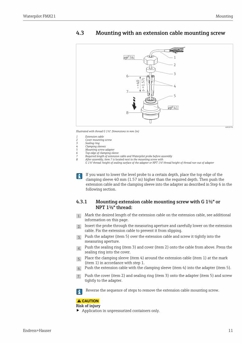
4.3 Mounting with an extension cable mounting screw
A0018794
Illustrated with thread G 1½". Dimensions in mm (in)
1 Extension cable2 Cover mounting screw3 Sealing ring4 Clamping sleeves5 Mounting screw adapter6 Top edge of clamping sleeve7 Required length of extension cable and Waterpilot probe before assembly8 After assembly, item 7 is located next to the mounting screw with
G 1½" thread: height of sealing surface of the adapter or NPT 1½" thread height of thread run-out of adapter
If you want to lower the level probe to a certain depth, place the top edge of the clamping sleeve 40 mm (1.57 in) higher than the required depth. Then push the extension cable and the clamping sleeve into the adapter as described in Step 6 in the following section.
4.3.1 Mounting extension cable mounting screw with G 1½" or NPT 1½" thread:
Mark the desired length of the extension cable on the extension cable, see additional information on this page.
Insert the probe through the measuring aperture and carefully lower on the extension cable. Fix the extension cable to prevent it from slipping.
Push the adapter (item 5) over the extension cable and screw it tightly into the measuring aperture.
Push the sealing ring (item 3) and cover (item 2) onto the cable from above. Press the sealing ring into the cover.
Place the clamping sleeve (item 4) around the extension cable (item 1) at the mark (item 1) in accordance with step 1.Push the extension cable with the clamping sleeve (item 4) into the adapter (item 5).
Push the cover (item 2) and sealing ring (item 3) onto the adapter (item 5) and screw tightly to the adapter.
Reverse the sequence of steps to remove the extension cable mounting screw.
CAUTION!
Risk of injury‣ Application in unpressurized containers only.
+4
0
()
+1
.57
1
6
8
7
2
3
4
5
36
41
Mounting Waterpilot FMX21
12 Endress+Hauser
4.4 Mounting the terminal box
The optional terminal box is mounted with four screws (M4). For the dimensions of the terminal box, please refer to Technical Information TI00431P/00/EN, "Mechanical construction" section (see also: www.endress.com Select Country Download Media Type: Documentation).
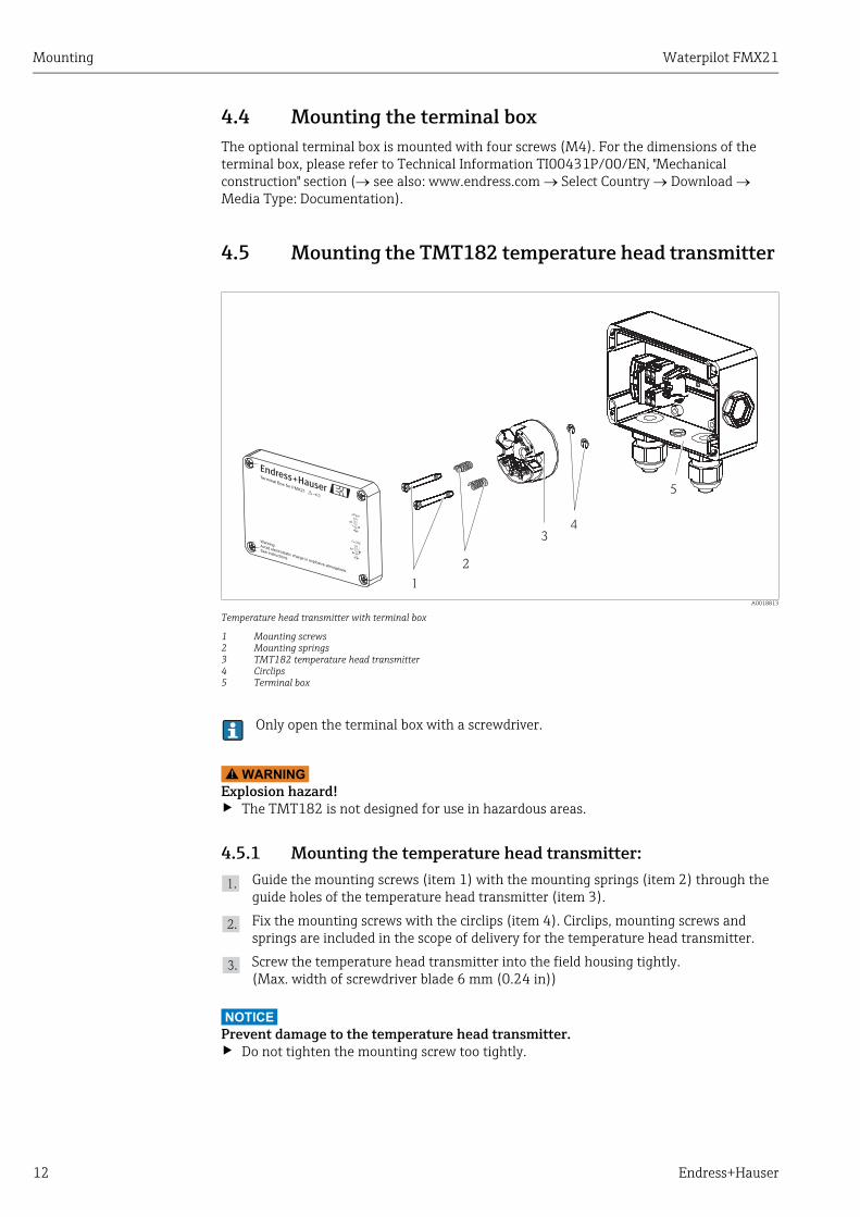
4.5 Mounting the TMT182 temperature head transmitter
A0018813
Temperature head transmitter with terminal box
1 Mounting screws2 Mounting springs3 TMT182 temperature head transmitter4 Circlips5 Terminal box
Only open the terminal box with a screwdriver.
WARNING!
Explosion hazard!‣ The TMT182 is not designed for use in hazardous areas.
4.5.1 Mounting the temperature head transmitter:
Guide the mounting screws (item 1) with the mounting springs (item 2) through the guide holes of the temperature head transmitter (item 3).
Fix the mounting screws with the circlips (item 4). Circlips, mounting screws and springs are included in the scope of delivery for the temperature head transmitter.
Screw the temperature head transmitter into the field housing tightly. (Max. width of screwdriver blade 6 mm (0.24 in))
NOTICE
Prevent damage to the temperature head transmitter.‣ Do not tighten the mounting screw too tightly.
1
3
2
6
5
4
3
CLOSE
90°
OPEN
90°
Warning:Avoid electrostatic charge in explosive atmosphere.
See instructions
Terminal Box for FMX21
1
2
34
5

Waterpilot FMX21 Mounting
Endress+Hauser 13
A0018696
NOTICE
A minimum distance of > 7 mm (> 0.28 in) must be maintained between the terminal strip and the TMT182 temperature head transmitter.
4.6 Mounting the terminal strip for the Pt100 passive (without TMT182)
If the FMX21 with optional Pt100 is supplied without the optional TMT182 temperature head transmitter, the terminal box is accompanied by a terminal strip for wiring the Pt100.
WARNING!
Explosion hazard!‣ The Pt100 and the terminal strip are not designed for use in hazardous areas.
A0018815
4.7 Post-mounting check
Check that all screws are firmly seated.
>7 (0.28)
mm (in)

Electrical connection Waterpilot FMX21
14 Endress+Hauser
5 Electrical connection
5.1 Connecting the device
WARNING!
Explosion hazard!‣ When using the measuring device in hazardous areas, installation must comply with the
corresponding national standards and regulations and the Safety Instructions or Installation or Control Drawings.
� The supply voltage must match the supply voltage on the nameplate ( ä 6).� Switch off the supply voltage before connecting the device.� The cable must end in a dry room or a suitable terminal box. The IP66/IP67 terminal box
with a GORE-TEX® from Endress+Hauser is suitable for outdoor installation ( ä 12).� Connect the device in accordance with the following diagrams. Reverse polarity protection
is integrated in the Waterpilot FMX21 and the TMT182 temperature head transmitter. Changing the polarities will not result in the destruction of the devices.
� A suitable circuit breaker should be provided for the device in accordance with IEC/EN 61010.
A0019441
A Waterpilot FMX21B Waterpilot FMX21 with Pt100 , version" NB" for feature 610 "Accessories" in the order code
a Not for FMX21 with an outer diameter of 29 mm (1.14 in)b 10.5 to 30 V DC (Ex), 10.5 to 35 V DCc 4 to 20 mAd Resistance (RL)e Pt100
Not for use in hazardous areas.
RD BK RD BKWH
YE BUBR
a
A B
e
) )
) )
c c
d d
b b
a
FMX21
FMX21

Waterpilot FMX21 Electrical connection
Endress+Hauser 15
A0018780
Waterpilot FMX21 with Pt100 and TMT182 temperature head transmitter , versions "NB" und "PT", feature 610 and 620 in the order code (see also Technical Information TI00431P/00/EN, "Ordering information" section)
a Not for FMX21 with an outer diameter of 29 mm (1.14 in) b 10.5 to 35 V DCc 4 to 20 mAd Resistance (RL)e TMT182 temperature head transmitter (4 to 20 mA HART)f 11.5 to 35 V DCg Pt100
Not for use in hazardous areas.
Wire colorsRD = red, BK = black, WH = white, YE = yellow, BU = blue, BR = brown
5.1.1 Connection data
Connection classification as per IEC 61010-1:
� Overvoltage category 1� Pollution degree 1
Connection data in the hazardous area
)
)
a
b
c
e
f
d
cd
g
RD BK
WH
YE BU
BR
6
5
4
32
1
FMX21
4 to 20 mA Ex ia IIC T4 to T6
Ui 30 V DC
Ii 133 mA
Pi 1.0 W
Ci 10.3 nF (sensor); 180 pF/m (cable)
Li 0 μH (sensor); 1 μH/m (cable)
Ta –10 °C (+14 °F) Ta +70 °C (+158 °F) for T4–10 °C (+14 °F) Ta +40 °C (+104 °F) for T6

Electrical connection Waterpilot FMX21
16 Endress+Hauser
5.1.2 Supply voltage
When the device is used in hazardous areas, the supply voltage is restricted as above in accordance with the requirements of the certificate in question.
5.1.3 Cable specification
� FMX21 with optional Pt100– Commercially available, shielded instrument cable– Terminals, terminal box: 0.08 to 2.5 mm2 (28 to 14 AWG)
� TMT182 temperature head transmitter (optional)– Commercially available instrument cable– Terminals, terminal box: 0.08 to 2.5 mm2 (28 to 14 AWG)– Transmitter terminals: max. 1.75 mm2 (16 AWG)
The extension cables are shielded for versions with outer diameters of 22 mm (0.87 in) or 42 mm (1.65 in).
In the following cases, Endress+Hauser recommends the use of a shielded cable as the cable extension:� For large distances between the end of the extension cable and the display and/or
evaluation unit.� For large distances between the end of the extension cable and the temperature head
transmitter.� When directly connecting the Pt100 signal to a display and/or evaluation unit.
5.1.4 Power consumption, current consumption
Version FMX21 FMX21 + Pt100 TMT182 temperature head transmitter
Version for the non-hazardous area 10.5 to 35 V DC 10.5 to 35 V DC 11.5 to 35 V DC
Version for the hazardous area 10.5 to 30 V DC – –
FMX21 FMX21 + Pt100 TMT182 temperature head transmitter
Power consumption 0.805 W at 35 V DC (non-hazardous area)
0.690 W at 30 V DC (hazardous area)
0.805 W at 35 V DC 0.805 W at 35 V DC
Current consumption Max. 23 mAMin. 3.6 mA
Max. 23 mAMin. 3.6 mAPt100: 0.6 mA
Max. 23 mAMin. 3.5 mA

Waterpilot FMX21 Electrical connection
Endress+Hauser 17
5.1.5 Load
The maximum load resistance depends on the supply voltage (U) and must be determined individually for each current loop, see formula and diagrams for FMX21 and temperature head transmitter.The total resistance resulting from the resistances of the connected devices, the connecting cable and, where applicable, the resistance of the extension cable may not exceed the load resistance value.
When operating using a HART handheld terminal or a PC with an operating program, a minimum communication resistance of 250 has to be taken into account.
FMX21 Temperature head transmitter
A0018753-EN A0018754-EN
RLmax – 2 0.09• • L – RU – 10.5 V
23 mA
�m
� add– RU – 11.5 V
0.023 A�RLmax add
RLmax = Max. load resistance []Radd = Additional resistances such as resistance of evaluation unit and/or display unit, cable resistance []U = Supply voltage [V]L = Simple length of extension cable [m] (cable resistance per wire 0.09 m)
A0018765
FMX21 load chart for estimating the load resistance. Additional resistances, such as the resistance of the extension cable, have to be subtracted from the value calculated as shown in the equation.
A0018766
Temperature head transmitter load chart for estimating the load resistance. Additional resistances have to be subtracted from the value calculated as shown in the equation.
413
630
195
1065
3520 2510.5 15
847
30
R[ ]�
U[ ]V
370
587
152
1022
3520 2511.5 15
804
30
R[ ]�
U[ ]V

Electrical connection Waterpilot FMX21
18 Endress+Hauser
5.2 Connecting the measuring unit
5.2.1 Overvoltage protection
To protect the Waterpilot and the TMT182 temperature head transmitter from large interference voltage peaks, Endress+Hauser recommends installing overvoltage protection upstream and downstream of the display and/or evaluation unit as shown in the graphic.
A0018941
A Power supply, display and evaluation unit with one input for Pt100B Power supply, display and evaluation unit with one input for 4 to 20 mAC Power supply, display and evaluation unit with two inputs for 4 to 20 mA
1 Waterpilot FMX21 HART2 Connection for integrated Pt100 temperature sensor in the FMX21 HART3 4 to 20 mA HART(Temperature)4 4 to 20 mA HART(Level)5 Overvoltage protection (OP), e.g. HAW from Endress+Hauser (not for use in hazardous areas) 6 Power supply
Further information on the TMT182 temperature head transmitter for HART applications from Endress+Hauser can be found in "Technical Information" TI00078R/09/EN.
1
3
4
3
4
5
5
5
5
5
5
5
6
6
6
2
A
B
B
C
2

Waterpilot FMX21 Electrical connection
Endress+Hauser 19
5.2.2 Connecting Commubox FXA195
The Commubox FXA195 connects intrinsically safe transmitters with the HART protocol to a computer's USB port. This allows remote operation of the transmitter using Endress+Hauser's FieldCare operating program. Power is supplied to the Commubox through the USB port. The Commubox is also suitable for connection to intrinsically safe circuits. See Technical Information TI00404F/00/EN for further information.
5.2.3 Connecting Field Xpert SFX
Compact, flexible and robust industry handheld terminal for remote configuration and for obtaining measured values via the HART current output (4 to 20 mA). For details, see Operating Instructions BA00060S/04/EN.
A0018811
1 Waterpilot FMX21 2 Necessary communication resistor 250 3 Computer with operating tool (e.g. FieldCare) 4 Commubox FXA195 (USB)5 Transmitter power supply unit, e.g. RN221N (with communication resistor)6 Field Xpert SFX7 VIATOR Bluetooth-Modem with cable connection
Only use certified operating devices in hazardous area!
WARNING!
Explosion hazard!‣ Do not change the battery of the handheld terminal in the hazardous area.‣ When using the measuring device in hazardous areas, installation must comply with the
applicable national standards and regulations and the Safety Instructions (XAs) or the Installation or Control Drawings (ZDs).
3
7 6
4
1
5
2

Electrical connection Waterpilot FMX21
20 Endress+Hauser
5.2.4 Connecting for air pressure compensation with external measured value
A0018757
1 Fieldgate FXA5202 Multidrop-Connector FXN5203 Cerabar4 Waterpilot FMX21
It is advisable to use an absolute pressure probe for applications in which condensation can occur. In the case of level measurement with an absolute pressure probe, the measured value is affected by fluctuations in the ambient air pressure. To correct the resulting measured error, you can connect an external absolute pressure sensor (e.g. Cerabar) to the HART signal cable, switch the waterpilot to the burst mode and the Cerabar to operate in mode "Electr. Delta P".
By switching on the application "Electr. Delta P", the external absolute pressure sensor calculates the difference between the two pressure signals and can thus determine the level precisely.Only one level measured value can be corrected in this way ( ä 39).
If using intrinsically safe devices, strict compliance with the rules for interconnecting intrinsically safe circuits as stipulated in IEC60079-14 (proof of intrinsic safety) is mandatory.
5.2.5 Connecting external temperature sensor/temperature head transmitter for density compensation
The Waterpilot FMX21 can correct measured errors that result from fluctuations in the density of the water caused by temperature. Users can choose from the following options:
Use the internally measured sensor temperature of the FMX21
The internally measured sensor temperature is calculated in the Waterpilot FMX21 for density compensation. The level signal is thus corrected according to the density characteristic line of the water ( ä 41).
Use the optional internal Pt100 temperature sensor for density compensation in a sui-table HART master (e.g. PLC)
The Waterpilot FMX21 is available with an optional Pt100 temperature sensor. Endress+Hauser additionally offers the TMT182 temperature head transmitter to convert the Pt100 signal to a 4 to 20 mA HART signal. The temperature and pressure signal is transmitted to the HART master (e.g. PLC) where a corrected level value can be generated using a stored linearization table or the density function (of a chosen medium) ä 42.
FX
N520
1 2 3 4

Waterpilot FMX21 Electrical connection
Endress+Hauser 21
A0018763
1 HART-Master, e.g. PLC (programmable logic controller)2 Multidrop-Connector FXN5203 TMT182 temperature head transmitter4 Waterpilot FMX21
Use an external temperature signal which is transmitted to the FMX21 via HART burst mode
The Waterpilot FMX21 is available with an optional Pt100 temperature sensor. In this case, the signal of the Pt100 is analyzed using a HART-compliant (at least HART 5.0) temperature transmitter that supports burst mode. The temperature signal can thus be transmitted to the FMX21. The FMX21 uses this signal for the density correction of the level signal ( ä 43).
The TMT182 temperature head transmitter is not suitable for this configuration.
A0018764
1 Fieldgate FXA5202 Multidrop-Connector FXN5203 TMT182 temperature head transmitter (burst mode)4 Waterpilot FMX21
Without additional compensation due to the anomaly of water, errors of up to 4 % may occur at a temperature of +70 °C (+158 °F), for example. With density compensation, this error can be decreased to 0.5 % in the entire temperature range from 0 to +70 °C (+32 to +158 °F).
1 2 3 4
FX
N520
FX
N520
1 2 3 4
For further information on the devices, please refer to the appropriate Technical Information:� TI00078R: Temperaturkopftransmitter TMT182 (4...20 mA HART)� TI00369F: Fieldgate FXA520� TI00400F: Multidrop-Connector FXN520

Operability Waterpilot FMX21
22 Endress+Hauser
5.3 Post-connection check
The following checks must be performed after completing electrical connection of the device:� Does the supply voltage match the specifications on the nameplate?� Is the device connected as per Section 5.1 "Switching on the device"?� Are all screws firmly tightened?� Optional terminal box: are the cable glands leaktight?
6 OperabilityEndress+Hauser offers comprehensive measuring point solutions with display and/or evaluation units for the Waterpilot FMX21 and TMT182 temperature head transmitter.
Please contact your Endress+Hauser sales representative, if you have any other questions. Contact addresses can be found on the Internet: www.endress.com/worldwide.
6.1 Overview of operation options
6.1.1 Operation via FieldCare
The FieldCare operating program is an Endress+Hauser plant asset management tool based on FDT technology. With FieldCare, you can configure all Endress+Hauser devices as well as devices fromother manufacturers that support the FDT standard. Hardware and software requirements can be found on the Internet: www..endress.com Search: FieldCare FieldCare Technical data
FieldCare supports the following functions:� Configuration of transmitters in online and offline mode� Loading and saving device data (upload/download)� Documentation of the measuring point
Connection options:� HART via Commubox FXA195 and the USB port of a computer� HART via Fieldgate FXA520
6.1.2 Operation via Field Xpert SFX
Compact, flexible and robust industry handheld terminal for remote configuration and for obtaining measured values via the HART current output (4 to 20 mA). For details, see Operating Instructions BA00060S/04/EN.
� Further information on FieldCare and software download can be found on the Internet (see: www.endress.com Select Country Download Text Search: FieldCare).
� Connecting Commubox FXA195 ( ä 19)� As not all internal device dependencies can be mapped in offline operation, the
consistency of the parameters must be checked before the parameters are transmitted to the device.

Waterpilot FMX21 Operability
Endress+Hauser 23
6.1.3 Locking/unlocking operation
Once you have entered all the parameters, you can lock your entries against unauthorized and undesired access. The "Operator code" parameter is used to lock the device.
The release code is defined in the "Code definition" parameter.
6.1.4 Resetting to factory settings (reset)
By entering a certain code, you can completely, or partially, reset the entries for the parameters to the factory settings ( ä 64, "System"). Enter the code by means of the "Enter reset code" parameter (menu path: Expert System Management Enter reset code).There are various reset codes for the device. The following table illustrates which parameters are reset by the particular reset codes. Operation has to be unlocked to be able to perform a reset ( ä 23, "Locking/unlocking operation").
Any customer-specific configurations carried out by the factory are not affected by a reset (customer-specific configuration remains). If you want to change the customer-specific settings configured at the factory, please contact Endress+Hauser Service. Since there is no specific service level, order code and serial number can be changed without a specific release code.
Parameter name Description
Operator codeEntry
Menu path:Setup Extended Setup User code
Use this function to enter a code to lock or unlock operation.
User input: � To lock: Enter a number the release code (value range: 1 to 65535).� To unlock: Enter the release code.
The release code is "0" in the order configuration. Another release code can be defined in the "Code definition" parameter.If the user has forgotten the release code, the release code will be visible and unlocked by entering the number "5864".
Factory setting:0
Parameter name Description
Code definitionEntry
Menu path:Setup Extended Setup Code definition
Use this function to enter a release code with which the device can be unlocked.
User input: � A number between 0 and 9999
Factory setting:0
Reset code Description and effect
62 PowerUp reset (warm start)‣ The device is restarted. Data are read back anew from the EEPROM (processor is
initialized again).‣ Any simulation which may be running is ended.
333 User reset‣ The device is restarted.‣ Any simulation which may be running is ended.‣ This code resets all the parameters apart from:
– Device tag– Linearization table– Operating hours– Event logbook– Current trim

Commissioning Waterpilot FMX21
24 Endress+Hauser
After a "Total reset" in FieldCare you have to press the "refresh" button in order to ensure that the measuring units are also reset.
7 Commissioning
7.1 Function check
Before commissioning your measuring point, ensure that the post-installation and post-connection check have been performed.
� For the "Post-installation" checklist ä 13)� For the "Post-connection" checklist ä 22)
7.2 Commissioning with FieldCare
The following languages are available for FieldCare:� German� English� French� Italian� Spanish� Japanese� Chinese simplified
The device is configured for the Pressure measuring mode as standard. The measuring range and the unit in which the measured value is transmitted correspond to the data on the nameplate.
7864 Total reset‣ The device is restarted.‣ Any simulation which may be running is ended.‣ This code resets all the parameters apart from:
– Operating hours– Event logbook
If a pressure smaller than the minimum permitted pressure or greater than the maxi-mum permitted pressure is present at the device, the following messages are output in succession:
1. "S140 Working range P" or "F140 Working range P" 2. "S841 Sensor range" or "F841 Sensor range" 3. "S971 Sensor range"
Depending on the setting in the "Alarm behavior"
Reset code Description and effect

Waterpilot FMX21 Commissioning
Endress+Hauser 25
7.2.1 Basic settings
� Start FieldCare and establish the connection to the Waterpilot FMX21. � Select the measuring mode and press "Enter" to confirm:
� Select the pressure unit and press "Enter" to confirm:
Parameter name Description
Measuring modeSelection
Select the measuring mode.The operating menu is structured differently depending on the measuring mode selected.
If the measuring mode is changed, no conversion takes place. The device has to be recalibrated or as per if the measuring mode is changed.
Options:� Pressure� Level
Factory setting:Pressure
Parameter name Description
Press. eng. unitSelection
Select the pressure unit.If a new pressure unit is selected, all pressure-specific parameters are converted and displayed with the new unit.
Options:� mbar, bar� mmH2O, mH2O, inH2O� ftH2O� Pa, kPa, MPa� psi� mmHg, inHg� kgf/cm2
Factory setting:mbar or bar depending on the sensor nominal measuring range, or as per order specifications

Commissioning Waterpilot FMX21
26 Endress+Hauser
7.2.2 Position adjustment
Due to orientation of the device, there may be a zero point shift in the pressure measured value. You can correct this shift with the following parameters:
7.2.3 Configuring the damping
Parameter name Description
Position adjustment (relative pressure sensor)Entry
Position adjustment – the pressure difference between the set point and the measured pressure must not be known.
Example:– Measured value = 2.2 mbar (0.033 psi)– You correct the measured value via the "Pos. zero adjust" parameter with the
"Confirm" option. This means that you assign the value 0.0 to the pressure present.
– Measured value (after pos. zero adjust) = 0.0 mbar– The current value is also corrected.
Factory setting:Abort
Position offset (absolute pressure sensor)Entry
Position adjustment – the pressure difference between zero (set point) and the measured pressure must be known.
Example:– Measured value = 982.2 mbar (15 psi)– You correct the measured value with the value entered (e.g. 2.2 mbar
(0.033 psi)) via the "Position offset" parameter. This means that you assign the value 980.0 to the pressure present.
– Measured value (after pos. zero adjust) = 980.0 mbar (15 psi)– The current value is also corrected.
Factory setting:0.0
Parameter name Description
Damping valueEntry
The damping affects the speed at which the measured value reacts to changes in pressure.Low damping: reacts quickly, measured value might fluctuate.High damping: reacts slowly, measured value is stable.
Factory setting:2.0 as per order specifications
Waterpilot FMX21 Commissioning
Endress+Hauser 27
7.3 Pressure measurement
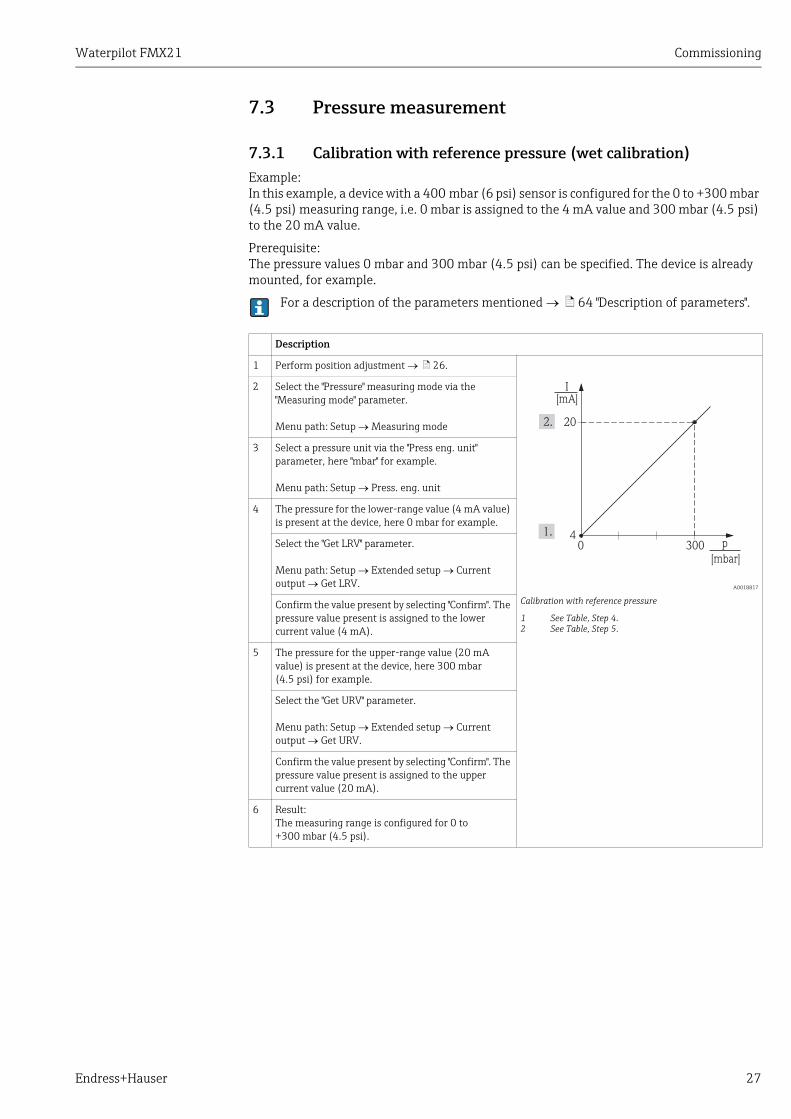
7.3.1 Calibration with reference pressure (wet calibration)
Example:In this example, a device with a 400 mbar (6 psi) sensor is configured for the 0 to +300 mbar (4.5 psi) measuring range, i.e. 0 mbar is assigned to the 4 mA value and 300 mbar (4.5 psi) to the 20 mA value.
Prerequisite:The pressure values 0 mbar and 300 mbar (4.5 psi) can be specified. The device is already mounted, for example.
For a description of the parameters mentioned ä 64 "Description of parameters".
Description
1 Perform position adjustment ä 26.
A0018817
Calibration with reference pressure
1 See Table, Step 4.2 See Table, Step 5.
2 Select the "Pressure" measuring mode via the "Measuring mode" parameter.
Menu path: Setup Measuring mode
3 Select a pressure unit via the "Press eng. unit" parameter, here "mbar" for example.
Menu path: Setup Press. eng. unit
4 The pressure for the lower-range value (4 mA value) is present at the device, here 0 mbar for example.
Select the "Get LRV" parameter.
Menu path: Setup Extended setup Current output Get LRV.
Confirm the value present by selecting "Confirm". The pressure value present is assigned to the lower current value (4 mA).
5 The pressure for the upper-range value (20 mA value) is present at the device, here 300 mbar (4.5 psi) for example.
Select the "Get URV" parameter.
Menu path: Setup Extended setup Current output Get URV.
Confirm the value present by selecting "Confirm". The pressure value present is assigned to the upper current value (20 mA).
6 Result:The measuring range is configured for 0 to +300 mbar (4.5 psi).
20
4
I[mA]
0 300 p
[mbar]

Commissioning Waterpilot FMX21
28 Endress+Hauser
7.3.2 Calibration without reference pressure (dry calibration)
Example:In this example, a device with a 400 mbar (6 psi) sensor is configured for the 0 to +300 mbar (4.5 psi) measuring range, i.e. 0 mbar is assigned to the 4 mA value and 300 mbar (4.5 psi) to the 20 mA value.
Prerequisite:This is a theoretical calibration, i.e. the pressure values for the lower and upper range are known.
Due to the orientation of the device, there may be pressure shifts in the measured value, i.e. the measured value is not zero in a pressureless condition. For information on how to perform position adjustment ä 26.
Description
1 Select the "Pressure" measuring mode via the "Measuring mode" parameter.
Menu path: Setup Measuring mode
A0018817
Calibration without reference pressure
1 See Table, Step 3.2 See Table, Step 4.
2 Select a pressure unit via the "Press eng. unit" parameter, here "mbar" for example.
Menu path: Setup Press. eng. unit
3 Select the "Set LRV" parameter.
Menu path: Setup Set LRV
Enter the value for the "Set LRV" parameter (here 0 mbar) and confirm. This pressure value is assigned to the lower current value (4 mA).
4 Select the "Set URV" parameter.
Menu path: Setup Set URV
Enter the value for the "Set URV" parameter (here 300 mbar (4.5 psi)) and confirm. This pressure value is assigned to the upper current value (20 mA).
5 Result:The measuring range is configured for 0 to +300 mbar (4.5 psi).
20
4
I[mA]
0 300 p
[mbar]
Waterpilot FMX21 Commissioning
Endress+Hauser 29
7.4 Level measurement
7.4.1 Information on level measurement
You have a choice of two methods for calculating the level: "In pressure" and "In height". The table in the "Overview of level measurement" section that follows provides you with an overview of these two measuring tasks.� The limit values are not checked, i.e. the values entered must be appropriate for the sensor
and the measuring task for the device to be able to measure correctly.� Customer-specific units are not possible.� The values entered for "Empty calib./Full calib.", "Empty pressure/Full pressure", "Empty
height/Full height" and "Set LRV/Set URV" must be at least 1% apart. The value will be rejected, and a message output, if the values are too close together.
7.4.2 Overview of level measurement
Measuring task Level selection
Measured variable options
Description Measured value display
Calibration takes place by entering two pressure/level value pairs.
"In pressure" Via the "Output unit" parameter: %, level, volume or mass units.
– Calibration with reference pressure (wet calibration), see ä 32, "Section 7.4.4"
– Calibration without reference pressure (dry calibration), ä 30, Section 7.4.3"
The measured value display and the"Level before lin" parameter display the measured value.
Calibration takes place by entering the density and two height/level value pairs.
"In height" – Calibration with reference pressure (wet calibration), ä 36, "Section 7.4.6"
– Calibration without reference pressure (dry calibration), ä 34, Section 7.4.5"

Commissioning Waterpilot FMX21
30 Endress+Hauser
7.4.3 "In pressure" level selection Calibration without reference pressure (dry calibration)
Example:In this example, the volume in a tank should be measured in liters. The maximum volume of 1000 liters (264 US gal) corresponds to a pressure of 400 mbar (6 psi). The minimum volume of 0 liters corresponds to a pressure of 0 mbar since the process isolating diaphragm of the probe is at the start of the level measuring range.
Prerequisite:� The measured variable is in direct proportion to the pressure. � This is a theoretical calibration i.e. the pressure and volume values for the lower and upper
calibration point must be known.
� The values entered for "Empty calib./Full calib." and" Set LRV/Set URV" must be at least 1% apart. The value will be rejected, and a message output, if the values are too close together. Other limit values are not checked, i.e. the values entered must be appropriate for the sensor and the measuring task for the device to be able to measure correctly.
� Due to the orientation of the device, there may be pressure shifts in the measured value, i.e. when the container is empty or partly filled, the measured value is not zero. For information on how to perform position adjustment ä 26.
Description
1 Select the "Level" measuring mode via the "Measuring mode" parameter.
Menu path: Setup Measuring mode
A0018818
Calibration without reference pressure – dry calibration
1 See Table, Steps 6 and 7. 2 See Table, Steps 8 and 9.
2 Select a pressure unit via the "Press eng. unit" parameter, here "mbar" for example.
Menu path: Setup Press. eng. unit
3 Select the "In pressure" level mode via the "Level selection" parameter.
Menu path: Setup Extended setup Level Level selection
4 Select a volume unit via the "Output unit" parameter, here "l" (liters) for example.
Menu path: Setup Extended setup Level Output unit
5 Select the "Dry" option via the "Calibration mode" parameter.
Menu path: Setup Extended setup Level Calibration mode
6 Enter the volume value for the lower calibration point via the "Empty calib." parameter, here "0 liter" for example.
Menu path: Setup Extended setup Level Empty calib.
7 Enter the pressure value for the lower calibration point via the "Empty pressure" parameter, here "0 mbar" for example.
Menu path: Setup Extended setup Level Empty pressure
1000 l
0 l
400 mbar
� = 1g
cm3

Waterpilot FMX21 Commissioning
Endress+Hauser 31
The measured variables %, level, volume and mass are available for this level mode. See Section 13.2 "Output unit".
8 Enter the volume value for the upper calibration point via the "Full calib." parameter, here "1000 liter" (264 US gal) for example.
Menu path: Setup Extended setup Level Full calib.
A0018819
A0018820
Calibration with reference pressure – wet calibration
1 See Table, Step 6.2 See Table, Step 7.3 See Table, Step 8.4 See Table, Step 9.5 See Table, Step 11.6 See Table, Step 12.
9 Enter the pressure value for the upper calibration point via the "Full pressure" parameter, here "400 mbar" (6.0 psi) for example.
Menu path: Setup Extended setup Level Full pressure
10 "Adjust density" contains the factory setting 1.0 but can be changed if required. The value pairs subsequently entered must correspond to this density.
Menu path: Setup Extended setup Level Adjust density
The process density can only be changed if automatic density correction is switched off (see Step 14).
11 Set the volume value for the lower current value (4 mA) via the "Set LRV" parameter.
Menu path: Setup Extended setup Current output Set LRV
12 Set the volume value for the upper current value (20 mA) via the "Set URV" parameter.
Menu path: Setup Extended setup Current output Set URV
13 If the process uses a medium other than the medium on which the calibration was based, the new density must be specified in the "Density process" parameter.
Menu path: Setup Extended setup Level Density process
The process density can only be changed if automatic density correction is switched off (see Step 14).
14 If density correction is required 1) : assign the temperature probe in the "Auto density corr." parameter.
Menu path: Expert Application Level Auto density corr.
15 Result:The measuring range is set for 0 to 1000 l.
1) A density correction is only possible for water. A temperature-density curve that is saved in the device is used. For this reason, the "Adjust density" (Step 10) and "Density process" (Step 13) parameters are not used here.
Description
1000
0
V
[l]
0 400 p[mbar]
20
4
I[mA]
0 1000 V
[l]

Commissioning Waterpilot FMX21
32 Endress+Hauser
7.4.4 "In pressure" level selection Calibration with reference pressure (wet calibration)
Example:In this example, the level in a tank should be measured in "m". The maximum level is 3 m (9.8 ft). The pressure range is set to 0 to 300 mbar (4.5 psi).
Prerequisite:� The measured variable is in direct proportion to the pressure. � The tank can be filled and emptied.
The values entered for "Empty calib./Full calib." and" Set LRV/Set URV" and the pressures present at the device must be at least 1% apart. The value will be rejected, and a message output, if the values are too close together. Other limit values are not checked, i.e. the values entered must be appropriate for the sensor and the measuring task for the device to be able to measure correctly.
Description
1 Perform "position adjustment" ä 26.
A0018824
Calibration with reference pressure – wet calibration
1 See Table, Step 9.2 See Table, Step 10.
2 Select the "Level" measuring mode via the "Measuring mode" parameter.
Menu path: Setup Measuring mode Level
3 Select a pressure unit via the "Press eng. unit" parameter, here "mbar" for example.
Menu path: Setup Press. eng. unit
4 Select the "In pressure" level mode via the "Level selection" parameter.
Menu path: Setup Extended setup Level Level selection
5 If density correction is required 1) : assign the temperature probe in the "Auto density corr." parameter.
Menu path: Expert Application Auto density corr.
6 Select a level unit via the "Output unit" parameter, here "m" for example.
Menu path: Setup Extended setup Level Output unit
7 Select the "Wet" option via the "Calibration mode" parameter.
Menu path: Setup Extended setup Level Calibration mode
1) A density correction is only possible for water. A temperature-density curve that is saved in the device is used. For this reason, the "Adjust density" (Step 8) and "Density process" (Step 13) parameters are not used here.
0 mbar
300 mbar3 m
0 m

Waterpilot FMX21 Commissioning
Endress+Hauser 33
The measured variables %, level, volume and mass are available for this level mode. See ä 64 "Output unit".
8 If the calibration is performed with a medium other than the process medium, enter the density of the calibration medium in the "Adjust density" parameter.
Menu path: Setup Extended setup Level Adjust density
The process density can only be changed if automatic density correction is switched off (see Step 5).
A0018825
A0018826
Calibration with reference pressure – wet calibration
1 See Table, Step 9.2 See Table, Step 10.3 See Table, Step 11.4 See Table, Step 12.
9 The hydrostatic pressure for the lower calibration point is present at the device, here "0 mbar" for example.
Select the "Empty calib." parameter.
Menu path: Setup Extended setup Level Empty calib.
Enter the level value, here "0 m" for example. Confirming the value means you assign the pressure value present to the lower level value.
10 The hydrostatic pressure for the upper calibration point is present at the device, here "300 mbar" (4.5 psi) for example.
Select the "Full calib." parameter.
Menu path: Setup Extended setup Level Full calib.
Enter the level value, here "3 m" (9.8 ft) for example. Confirming the value means you assign the pressure value present to the upper level value.
11 Set the level value for the lower current value (4 mA) by means of "Set LRV", here "0 m" for example.
Menu path: Setup Extended setup Current output Set LRV
12 Set the level value for the upper current value (20 mA) by means of "Set URV", here "3 m" (9.8 ft) for example.
Menu path: Setup Extended setup Current output Set URV.
13 If the calibration was performed with a medium other than the process medium, enter the density of the process medium in the "Density process" parameter.
Menu path: Setup Extended setup Level Density process
The process density can only be changed if automatic density correction is switched off (see Step 5).
14 Result:The measuring range is set for 0 to 3 m (9.8 ft).
Description
3
0
h[m]
0 300 p
[mbar]
20
4
I[mA]
0 3 h[m]

Commissioning Waterpilot FMX21
34 Endress+Hauser
7.4.5 "In height" level selection Calibration without reference pressure (dry calibration)
Example:In this example, the volume in a tank should be measured in liters. The maximum volume of 1000 liters (264 US gal) corresponds to a level of 4 m (13 ft). The minimum volume of 0 liters corresponds to a level of 0 m since the process isolating diaphragm of the probe is at the start of the level measuring range.
Prerequisite:� The measured variable is in direct proportion to the pressure. � This is a theoretical calibration i.e. the height and volume values for the lower and upper
calibration point must be known.
� The values entered for "Empty calib./Full calib.", "Empty height/Full height" and" Set LRV/Set URV" must be at least 1% apart. The value will be rejected, and a message output, if the values are too close together. Other limit values are not checked, i.e. the values entered must be appropriate for the sensor and the measuring task for the device to be able to measure correctly.
� Due to the orientation of the device, there may be pressure shifts in the measured value, i.e. when the container is empty or partly filled, the measured value is not zero. For information on how to perform position adjustment ä 26.
Description
1 Select the "Level" measuring mode via the "Measuring mode" parameter.
Menu path: Setup Measuring mode
A0018827
Calibration without reference pressure – dry calibration
1 See Table, Step 10 and 11.2 See Table, Steps 13 and 14.3 See Table, Steps 12.
2 Select a pressure unit via the "Press eng. unit" parameter, here "mbar" for example.
Menu path: Setup Press. eng. unit
3 Select the "In height" level mode via the "Level selection" parameter.
Menu path: Setup Extended setup Level Level selection
4 If density correction is required 1) : assign the temperature probe in the "Auto density corr." parameter.
Menu path: Expert Application Auto density corr.
5 Select a volume unit via the "Output unit" parameter, here "l" (liters) for example.
Menu path: Setup Extended setup Level Output unit
6 Select a height unit via the "Height unit" parameter, here "m" for example.
Menu path: Setup Extended setup Level Height unit
7 Select the "Dry" option via the "Calibration mode" parameter.
Menu path: Setup Extended setup Level Calibration mode
1) A density correction is only possible for water. A temperature-density curve that is saved in the device is used. For this reason, the "Adjust density" (Step 12) and "Density process" (Step 15) parameters are not used here.
1000 l
0 l
4 m
� = 1g
cm3

Waterpilot FMX21 Commissioning
Endress+Hauser 35
The measured variables %, level, volume and mass are available for this level mode Chap. 13.2 "Output unit".
8 Enter the volume value for the lower calibration point via the "Empty calib." parameter, here "0 liter" for example.
Menu path: Setup Extended setup Level Empty calib.
A0018828
A0018830
A0018832
Calibration with reference pressure – wet calibration
1 See Table, Step 12.2 See Table, Step 8.3 See Table, Step 9.4 See Table, Step 10.5 See Table, Step 11.6 See Table, Step 13.7 See Table, Step 14.
9 Enter the height value for the lower calibration point via the "Empty height" parameter, here "0 m" for example.
Menu path: Setup Extended setup Level Empty height
10 Enter the volume value for the upper calibration point via the "Full calib." parameter, here "1000 liter" (264 US gal) for example.
Menu path: Setup Extended setup Level Full calib.
11 Enter the height value for the upper calibration point via the "Full height" parameter, here "4 m" (13 ft) for example.
Menu path: Setup Extended setup Level Full height
12 Enter the density of the medium via the "Adjust density" parameter, here "1 g/cm3" for example.
Menu path: Setup Extended setup Level Adjust density
13 Set the volume value for the lower current value (4 mA) via the "Set LRV" parameter.
Menu path: Setup Extended setup Current output Set LRV
14 Set the volume value for the upper current value (20 mA) via the "Set URV" parameter.
Menu path: Setup Extended setup Current output Set URV
15 If the process uses a medium other than the medium on which the calibration was based, the new density must be specified in the "Density process" parameter.
Menu path: Setup Extended setup Level Density process
The process density can only be changed if automatic density correction is switched off (see Step 4).
16 Result:The measuring range is set for 0 to 1000 l.
Description
4.08
0
h[m]
400 p
[mbar]
h =p
� · g
� = 1g
cm3
1000
0
V[l]
4.0 h[m]
h =p
� · g
0.0
20
4
I[mA]
1000 V[l]
0.0

Commissioning Waterpilot FMX21
36 Endress+Hauser
7.4.6 "In height" level selection Calibration with reference pressure (wet calibration)
Example:In this example, the volume in a tank should be measured in liters. The maximum volume of 1000 liters (264 US gal) corresponds to a level of 4 m (13 ft). The minimum volume of 0 liters corresponds to a level of 0 m since the process isolating diaphragm of the probe is at the start of the level measuring range. The density of the fluid is 1 g/cm3.
Prerequisite:� The measured variable is in direct proportion to the pressure. � The tank can be filled and emptied.
The values entered for "Empty calib./Full calib." and" Set LRV/Set URV" and the pressures present at the device must be at least 1% apart. The value will be rejected, and a message output, if the values are too close together. Other limit values are not checked, i.e. the values entered must be appropriate for the sensor and the measuring task for the device to be able to measure correctly.
Description
1 Perform position adjustment. See ä 26.
A0018827
Calibration with reference pressure – wet calibration
1 See Table, Step 9.2 See Table, Step 10.3 See Table, Step 11.
2 Select the "Level" measuring mode via the "Measuring mode" parameter.
Menu path: Setup Measuring mode
3 Select the "In height" level mode via the "Level selection" parameter.
Menu path: Setup Extended setup Level Level selection
4 If density correction is required 1) : assign the temperature probe in the "Auto density corr." parameter.
Menu path: Expert Application Auto density corr.
5 Select a pressure unit via the "Press eng. unit" parameter, here mbar for example.
Menu path: Setup Press. eng. unit
6 Select a volume unit via the "Output unit" parameter, here "l" (liters) for example.
Menu path: Setup Extended setup Level Output unit
7 Select a height unit via the "Height unit" parameter, here "m" for example.
Menu path: Setup Extended setup Level Height unit
1) A density correction is only possible for water. A temperature-density curve that is saved in the device is used. For this reason, the "Adjust density" (Step 11) and "Density process" (Step 14) parameters are not used here.
1000 l
0 l
4 m
� = 1g
cm3
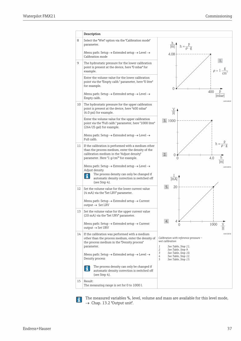
Waterpilot FMX21 Commissioning
Endress+Hauser 37
The measured variables %, level, volume and mass are available for this level mode, Chap. 13.2 "Output unit".
8 Select the "Wet" option via the "Calibration mode" parameter.
Menu path: Setup Extended setup Level Calibration mode
A0018828
A0018834
A0018838
Calibration with reference pressure – wet calibration
1 See Table, Step 11.2 See Table, Step 9.3 See Table, Step 10.4 See Table, Step 12.5 See Table, Step 13.
9 The hydrostatic pressure for the lower calibration point is present at the device, here "0 mbar" for example.
Enter the volume value for the lower calibration point via the "Empty calib." parameter, here "0 liter" for example.
Menu path: Setup Extended setup Level Empty calib.
10 The hydrostatic pressure for the upper calibration point is present at the device, here "400 mbar" (6.0 psi) for example.
Enter the volume value for the upper calibration point via the "Full calib." parameter, here "1000 liter" (264 US gal) for example.
Menu path: Setup Extended setup Level Full calib.
11 If the calibration is performed with a medium other than the process medium, enter the density of the calibration medium in the "Adjust density" parameter. Here "1 g/cm" for example.
Menu path: Setup Extended setup Level Adjust density
The process density can only be changed if automatic density correction is switched off (see Step 4).
12 Set the volume value for the lower current value (4 mA) via the "Set LRV" parameter.
Menu path: Setup Extended setup Current output Set LRV
13 Set the volume value for the upper current value (20 mA) via the "Set URV" parameter.
Menu path: Setup Extended setup Current output Set URV
14 If the calibration was performed with a medium other than the process medium, enter the density of the process medium in the "Density process" parameter.
Menu path: Setup Extended setup Level Density process
The process density can only be changed if automatic density correction is switched off (see Step 4).
15 Result:The measuring range is set for 0 to 1000 l.
Description
4.08
0
h[m]
400 p
[mbar]
h =p
� · g
� = 1g
cm3
1000
0
V[l]
4.0 h[m]
h =p
� · g
0
20
4
I[mA]
1000 V[l]
0
Commissioning Waterpilot FMX21
38 Endress+Hauser
7.4.7 Calibration with partially-filled tank (wet calibration)
Example:In this example a wet calibration is shown when it is not possible to empty the vessel and then fill it up to 100%. Here a 20% filling is used as “Empty” and a “25%” filling is used as “Full” calibration point. The calibration is then extended to 0% ... 100% and LRV / URV are adjusted accordingly.
Prerequisite:The default value in the level mode for calibration mode is “Wet”.However, it can be changed via: Setup Extended Setup Level Calibration mode
It is also possible to use different liquids for the adjustment. In this case you have to enter the appropriate densities at following menu path:
� Setup Ext. Setup Level Adjust density (e.g. 1.0 kg/l for water)� Setup Ext. Setup Level Process density (e.g. 0.8 kg/l for oil)
Description
1 Select the "Level" measuring mode via the "Measuring mode" parameter.
Menu path: Setup Measuring mode
A0018841
Calibration with partially-filled tank
1 See Table, Step 22 See Table, Step 3
2 Set value for "Empty calib." with acting pressure for Level e.g. 20%.
Menu path: Setup Extended Setup Level Empty calibration
3 Set value for "Full calib." with acting pressure for Level e.g. 25%.
Menu path: Setup Extended Setup Level Full calibration
4 The values for pressure for full or empty vessels are measured automatically at adjustment.As the transmitter automatically sets the pressure values that suit to empty and full calibration to min and max pressure that cause the output current, it is necessary to set the right upper range value (URV) and lower range value (LRV).
20%
20%
25%
Waterpilot FMX21 Commissioning
Endress+Hauser 39
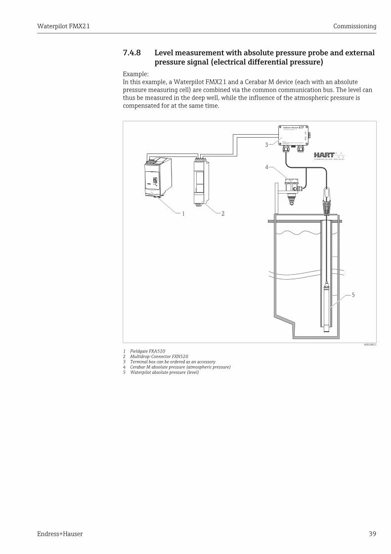
7.4.8 Level measurement with absolute pressure probe and external pressure signal (electrical differential pressure)
Example:In this example, a Waterpilot FMX21 and a Cerabar M device (each with an absolute pressure measuring cell) are combined via the common communication bus. The level can thus be measured in the deep well, while the influence of the atmospheric pressure is compensated for at the same time.
A0018821
1 Fieldgate FXA5202 Multidrop-Connector FXN5203 Terminal box can be ordered as an accessory4 Cerabar M absolute pressure (atmospheric pressure)5 Waterpilot absolute pressure (level)
FX
N520
OPEN
CLOSE
90°
90°
Warning:Avoid electrostatic charge in explosive atmosphere.See instructions
Terminal Box for FMX21
1 2
4
3
5

Commissioning Waterpilot FMX21
40 Endress+Hauser
� It is not permitted to reverse the assignment of the measuring points to the direction of communication.
� The measured value of the transmitting device (via burst) must always be greater than the measured value of the receiving device (via the "Electr. Delta P" mode).
� Adjustments that result in an offset of the pressure values (e.g. position adjustment, trim) must always be performed in accordance with the individual sensor and its orientation, irrespective of the "Electr. Delta P" application.
� Other settings result in non-permitted use of the "Electr. Delta P" mode and can lead to incorrect measured values.
DescriptionAdjustment of the level sensor (Waterpilot)
1 Select the "Pressure" measuring mode via the "Measuring mode" parameter.
Menu path: Setup Measuring mode
2 Select a pressure unit via the "Press eng. unit" parameter, here "mbar" for example.
Menu path: Setup Press. eng. unit
3 The sensor is unpressurized, perform position adjustment ( ä 26).
4 Switch on burst mode via the "Burst mode" parameter
Menu path: Expert Communication HART Config.
5 Set the output current to "Fixed" 4.0 mA via the "Current mode" parameter
Menu path: Expert Communication HART Config.
6 Configure an address 0 using the "Bus address" parameter, e.g. bus address = 1.(HART 5.0 master: Range 0 to 15, where address = 0 calls up the "Signaling" setting; HART 6.0 master: range 0 to 63)
Menu path: Expert Communication HART Config.
DescriptionAdjustment of the level sensor (Waterpilot)
1 Select the "Level" measuring mode via the "Measuring mode" parameter.
Menu path: Setup Measuring mode
2 Select a pressure unit via the "Press eng. unit" parameter, here "mbar" for example.
Menu path: Setup Press. eng. unit
3 The sensor is unpressurized, perform position adjustment ( ä 26).
4 Set the output current to "Fixed" 4.0 mA via the "Current mode" parameter
Menu path: Expert Communication HART Config.
5 Configure an address 0 using the "Bus address" parameter, e.g. bus address = 2.(HART 5.0 master: Range 0 to 15, where address = 0 calls up the "Signaling" setting; HART 6.0 master: range 0 to 63)
Menu path: Expert Communication HART Config.
6 Activate the reading of a value sent externally in burst mode via the "Electr. Delta P" parameter
Menu path: Expert Application
7 Perform level adjustment (wet or dry), ä 32 ff.
8 Result: The measured value output by the atmospheric pressure sensor equals the level in the deep well (dif-ferential signal) and can be read out by means of a HART request of the address of the atmospheric pressure sensor.

Waterpilot FMX21 Commissioning
Endress+Hauser 41
7.4.9 Automatic density compensation with the internally measured sensor temperature
Example:In this example, a Waterpilot FMX21 is used for level measurement in water. The change in the water density caused by changing temperatures is automatically factored into the level signal by activating automatic density compensation.
A0018822
1 HART-Master, e.g. PLC (programmable logic controller)2 Waterpilot FMX21
1
2
DescriptionAdjustment of the Waterpilot for level measurement
1 Select the "Level" measuring mode via the "Measuring mode" parameter.
Menu path: Setup Measuring mode
2 Select a pressure unit via the "Press eng. unit" parameter, here "mbar" for example.
Menu path: Setup Press. eng. unit
3 The sensor is unpressurized, perform position adjustment ( ä 26).
4 Set the "Auto density corr." parameter to Sensor temperature.
Menu path: Expert Application
5 Perform level adjustment (wet or dry), ä 32 ff.
6 Result: The measured value output by the Waterpilot equals the level in the deep well corrected by means of the density characteristic line of the water.

Commissioning Waterpilot FMX21
42 Endress+Hauser
7.4.10 Automatic density compensation using an integrated Pt100 value for calculation in a suitable HART master (e.g. PLC)
Example:In this example, the FMX21 with an integrated Pt100 and a temperature head transmitter with HART communication (e.g. TMT182) are combined via the common communication bus. The temperature and pressure signal is transmitted to the HART master (e.g. PLC) where a corrected level value can be generated using a stored linearization table or the density function (of a chosen medium). A pressure signal and a temperature signal can thus be generated with a chosen density function to compensate for a level.
A0018763
1 HART-Master, e.g. PLC (programmable logic controller)2 Multidrop-Connector FXN5203 TMT182 Temperature head transmitter4 Waterpilot FMX21
1 2 3 4
FX
N520
DescriptionAdjustment of the Waterpilot for pressure measurement
1 Select the "Pressure" measuring mode via the "Measuring mode" parameter.
Menu path: Setup Measuring mode
2 Select a pressure unit via the "Press eng. unit" parameter, here "mbar" for example.
Menu path: Setup Press. eng. unit
3 The sensor is unpressurized, perform position adjustment ( ä 26).
4 Set the output current to "Fixed" 4.0 mA via the "Current mode" parameter.
Menu path: Expert Communication HART Config.
5 Perform level adjustment (wet or dry), ä 32 ff.
6 Configure an address 0 using the "Bus address" parameter, e.g. bus address =1.(HART 5.0 master: Range 0 to 15, where address = 0 calls up the "Signaling" setting; HART 6.0 master: range 0 to 63)
Menu path: Expert Communication HART Config.The output current of the temperature transmitter used must also be set to Fixed and a HART address other than zero (e.g. address = 2) is configured.
7 Result: A corrected level value can be determined for a chosen medium using a suitable density function by calculating the pressure signal and temperature signal in a suitable HART master (e.g. PLC).

Waterpilot FMX21 Commissioning
Endress+Hauser 43
7.4.11 Automatic density compensation using an external tempera-ture value for calculation in the FMX21
Example:In this example, the FMX21 with an integrated Pt100 and a HART-compliant temperature transmitter are combined via the common communication bus. In this case, the signal of the Pt100 is analyzed using a HART-compliant (at least HART 5.0) temperature head transmitter that supports burst mode. The change in the water density caused by changing temperatures is automatically factored into the level signal by activating automatic density compensation.
A0018764
1 Fieldgate FXA5202 Multidrop-Connector FXN5203 TMT182 Temperature head transmitter (burst mode)4 Waterpilot FMX21
Temperature head transmitter TMT182 is not suitable for this configuration.
FX
N520
1 2 3 4
DescriptionConfiguring the HART-compliant temperature head transmitter (min. HART 5.0) with burst function
The output current of the temperature head transmitter used should be set to Fixed and must have a HART address other than zero (e.g. address = 1) configured.The burst function must then be switched on with HART command 1.This step should be performed before the procedure described below in order to avoid a HART input error of the FMX21 being output during commissioning.
Adjustment of the Waterpilot for level measurement
1 Select the "Level" measuring mode via the "Measuring mode" parameter.
Menu path: Setup Measuring mode
2 Select a pressure unit via the "Press eng. unit" parameter, here "mbar" for example.
Menu path: Setup Press. eng. unit
3 The sensor is unpressurized, perform position adjustment ( ä 26).
4 Set the "Auto density corr." parameter to "External value".
Menu path: Expert Application
5 Perform level adjustment (wet or dry), ä 32 ff.
6 Result: The measured value output by the Waterpilot equals the level in the deep well corrected by means of the density characteristic line of the water.

Commissioning Waterpilot FMX21
44 Endress+Hauser
7.5 Linearization
7.5.1 Semiautomatic entry of the linearization table
Example:In this example, the volume in a tank with a conical outlet should be measured in "m3".
Prerequisite:� The tank can be filled or be emptied. The linearization characteristic must rise
continuously.� The "Level" operating mode has been selected.
For a description of the parameters mentioned ä 64.
Description
1 Select the "Semiautom. entry" option via the "Lin. mode" parameter.
Menu path: Setup Extended setup Linearization Lin. mode
A0018843
2 Select the volume/mass unit via the "Unit after lin." parameter, e. g. "m3".
Menu path: Setup Extended setup Linearization Unit after lin.
3 Fill the tank to the height of the 1st point.
3.5
0 3.0
V[m ]
3
h[m]
0

Waterpilot FMX21 Commissioning
Endress+Hauser 45
4 Enter the number of the point in the table via the "Line-numb." parameter.
Menu path: Setup Extended setup Linearization Line-numb
A0018849
A0018853
Semiautomatic entry of the linearization table
The current level is displayed via the "X-value" parameter.
Menu path: Setup Extended setup Linearization X-value
Using the "Y-value" parameter, enter the associated volume value, here "0 m3" for example, and confirm the value. Menu path: Setup Extended setup Linearization Y-value
5 To enter another point in the table, select the "Next point" option via the "Edit table" parameter. Enter the next point as explained in Step 4.
Menu path: Setup Extended setup Linearization Edit table
6 Once all the points have been entered in the table, select the "Activate table" option via the "Lin. mode" parameter.
Menu path: Setup Extended setup Linearization Lin. mode
7 Result:The measured value after linearization is displayed.
1. Error message F510 "Linearization" and alarm current as long as the table is being entered and until the table is activated.
2. The 0% value (= 4 mA) is defined by the lowest pair of values in the table.The 100% value (= 20 mA) is defined by the maximum pair of values point in the table.
3. You can change the allocation of the volume or mass values to the current values using the "Set LRV" and "Set URV" parameters.
Description
3.5
00 3.0 h
[m]
V[m ]
3
20
4
I[mA]
3.5 V[m ]
30
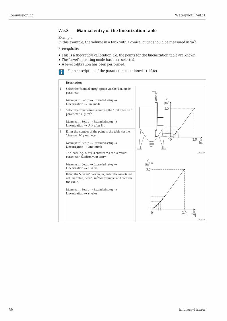
Commissioning Waterpilot FMX21
46 Endress+Hauser
7.5.2 Manual entry of the linearization table
Example:In this example, the volume in a tank with a conical outlet should be measured in "m3".
Prerequisite:
� This is a theoretical calibration, i.e. the points for the linearization table are known.� The "Level" operating mode has been selected.� A level calibration has been performed.
For a description of the parameters mentioned ä 64.
Description
1 Select the "Manual entry" option via the "Lin. mode" parameter.
Menu path: Setup Extended setup Linearization Lin. mode
A0018843
A0018849
2 Select the volume/mass unit via the "Unit after lin." parameter, e. g. "m3".
Menu path: Setup Extended setup Linearization Unit after lin.
3 Enter the number of the point in the table via the "Line-numb." parameter.
Menu path: Setup Extended setup Linearization Line-numb
The level (e.g. "0 m") is entered via the "X-value" parameter. Confirm your entry.
Menu path: Setup Extended setup Linearization X-value
Using the "Y-value" parameter, enter the associated volume value, here "0 m3" for example, and confirm the value. Menu path: Setup Extended setup Linearization Y-value
3.5
0 3.0
V[m ]
3
h[m]
0
3.5
00 3.0 h
[m]
V[m ]
3

Waterpilot FMX21 Commissioning
Endress+Hauser 47
4 To enter another point in the table, select the "Next point" option via the "Edit table" parameter. Enter the next point as explained in Step 3.
Menu path: Setup Extended setup Linearization Edit table
A0018853
Manual entry of the linearization table
5 Once all the points have been entered in the table, select the "Activate table" option via the "Lin. mode" parameter.
Menu path: Setup Extended setup Linearization Lin. mode
6 Result:The measured value after linearization is displayed.
1. Error message F510 "Linearization" and alarm current as long as the table is being entered and until the table is activated.
2. The 0% value (= 4 mA) is defined by the lowest pair of values in the table.The 100% value (= 20 mA) is defined by the maximum pair of values in the table.
3. You can change the allocation of the volume or mass values to the current values using the "Set LRV" and "Set URV" parameters.
Description
20
4
I[mA]
3.5 V[m ]
30

Troubleshooting Waterpilot FMX21
48 Endress+Hauser
8 Troubleshooting
8.1 Messages
The following table lists the messages that can occur. The Diagnostic code parameter shows the message with the highest priority. The device has four different status information codes according to NE107:
� F = failure� M (warning) = maintenance required� C (warning) = function check� S (warning) = outside specification (deviations from the permitted ambient or process
conditions determined by the device with the self-monitoring function, or errors in the device itself indicate that the measuring uncertainty is greater than what would be expected under normal operating conditions).
For support and further information, please contact Endress+Hauser Service.
Diagnostic code
Error message Cause Remedial action
0 No error – –
C412 Backup in prog. – Downloading. Wait for download to complete
C482 Current simul. – Current output simulation is switched on, i.e. the device is not measuring at present.
End the simulation
C484 Error simul. – Fault state simulation is switched on, i.e. the device is not measuring at present.
End the simulation
C485 Measure simul. – Simulation is switched on, i.e. the device is not measuring at present.
End the simulation
C824 Process pressure – Overpressure or low pressure present.
– This message normally only appears briefly.
– Electromagnetic effects are greater than specified in the technical data.
1. Check the pressure value2. Restart the device3. Perform a reset
F002 Unknown sensor – Sensor does not suit the device (electronic sensor nameplate).
Contact Endress+Hauser Service.
F062 Sensor conn. – Cable connection between the sensor and main electronics is disconnected.
– Sensor defective.– Electromagnetic effects are greater
than specified in the technical data. This message normally only appears briefly.
Check the sensor cable
F081 Initialization – Cable connection between the sensor and main electronics is disconnected.
– Sensor defective.– Electromagnetic effects are greater
than specified in the technical data. This message normally only appears briefly.
1. Perform a reset2. Check the sensor cable
F083 Permanent mem. – Sensor defective.– Electromagnetic effects are greater
than specified in the technical data. This message normally only appears briefly.
1. Restart the device
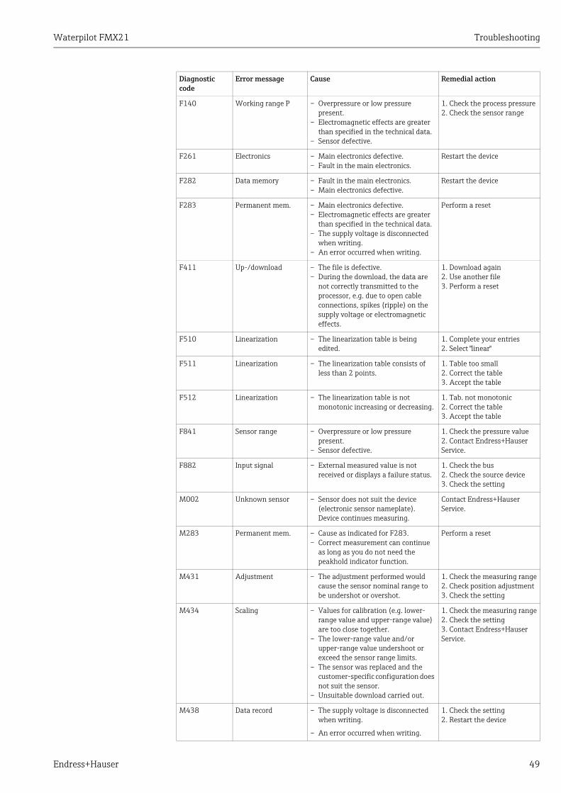
Waterpilot FMX21 Troubleshooting
Endress+Hauser 49
F140 Working range P – Overpressure or low pressure present.
– Electromagnetic effects are greater than specified in the technical data.
– Sensor defective.
1. Check the process pressure2. Check the sensor range
F261 Electronics – Main electronics defective.– Fault in the main electronics.
Restart the device
F282 Data memory – Fault in the main electronics.– Main electronics defective.
Restart the device
F283 Permanent mem. – Main electronics defective.– Electromagnetic effects are greater
than specified in the technical data.– The supply voltage is disconnected
when writing.– An error occurred when writing.
Perform a reset
F411 Up-/download – The file is defective.– During the download, the data are
not correctly transmitted to the processor, e.g. due to open cable connections, spikes (ripple) on the supply voltage or electromagnetic effects.
1. Download again2. Use another file3. Perform a reset
F510 Linearization – The linearization table is being edited.
1. Complete your entries2. Select "linear"
F511 Linearization – The linearization table consists of less than 2 points.
1. Table too small2. Correct the table3. Accept the table
F512 Linearization – The linearization table is not monotonic increasing or decreasing.
1. Tab. not monotonic2. Correct the table3. Accept the table
F841 Sensor range – Overpressure or low pressure present.
– Sensor defective.
1. Check the pressure value2. Contact Endress+Hauser Service.
F882 Input signal – External measured value is not received or displays a failure status.
1. Check the bus2. Check the source device3. Check the setting
M002 Unknown sensor – Sensor does not suit the device (electronic sensor nameplate). Device continues measuring.
Contact Endress+Hauser Service.
M283 Permanent mem. – Cause as indicated for F283.– Correct measurement can continue
as long as you do not need the peakhold indicator function.
Perform a reset
M431 Adjustment – The adjustment performed would cause the sensor nominal range to be undershot or overshot.
1. Check the measuring range2. Check position adjustment3. Check the setting
M434 Scaling – Values for calibration (e.g. lower-range value and upper-range value) are too close together.
– The lower-range value and/or upper-range value undershoot or exceed the sensor range limits.
– The sensor was replaced and the customer-specific configuration does not suit the sensor.
– Unsuitable download carried out.
1. Check the measuring range2. Check the setting3. Contact Endress+Hauser Service.
M438 Data record – The supply voltage is disconnected when writing.
– An error occurred when writing.
1. Check the setting2. Restart the device
Diagnostic code
Error message Cause Remedial action

Troubleshooting Waterpilot FMX21
50 Endress+Hauser
8.2 Malfunctions of Waterpilot FMX21 with optional Pt100
M882 Input signal – External measured value displays a warning status.
1. Check the bus2. Check the source device3. Check the setting
S110 Working range T – High temperature or low temperature present.
– Electromagnetic effects are greater than specified in the technical data.
– Sensor defective.
1. Check the process temperature2. Check the temperature range
S140 Working range P – Overpressure or low pressure present.
– Electromagnetic effects are greater than specified in the technical data.
– Sensor defective.
1. Check the process pressure2. Check the sensor range
S822 Process temp. – The temperature measured in the sensor is higher than the upper nominal temperature of the sensor.
– The temperature measured in the sensor is lower than the lower nominal temperature of the sensor.
1. Check the temperature2. Check the setting
S841 Sensor range – Overpressure or low pressure present.
– Sensor defective.
1. Check the pressure value2. Contact Endress+Hauser Service.
S971 Adjustment – The current is outside the permitted range of 3.8 to 20.5 mA.
– The pressure present is outside the set measuring range (but might be within the sensor range).
– The adjustment performed would cause the sensor nominal range to be undershot or overshot.
1. Check the pressure value2. Check the measuring range3. Check the setting
Error description Cause Measures
No measuring signal 4 to 20 mA cable not connected correctly
Connect device in accordance with ä 14, Section 5.1.
No power supplied via the 4 to 20 mA cable
Check current loop.
Supply voltage too low (min. 10.5 V DC)
– Check supply voltage.– Overall resistance greater than
max. load resistance ä 14, Section 5.1.
Waterpilot defective Replace the Waterpilot.
Temperature measured value is inaccurate/incorrect (only for Waterpilot FMX21 with Pt100)
Pt100 connected in 2-wire circuit, cable resistance was not compensated
– Compensate cable resistance.– Connect Pt100 as 3-wire or 4-
wire circuit.
Diagnostic code
Error message Cause Remedial action

Waterpilot FMX21 Maintenance
Endress+Hauser 51
8.3 Malfunctions of TMT182 temperature head transmitter
8.4 Firmware history
9 MaintenanceNo special maintenance work is required for the Waterpilot and for the optional TMT182 temperature head transmitter.
Terminal box: Keep the pressure compensation tube and GORE-TEX® filter free from contamination.
9.1 Exterior cleaning
Please note the following points when cleaning the devices externally:� The cleaning agents used should not corrode the housing surface and the seals.
Information on this can be found on the nameplate ( ä 6).� Mechanical damage to the process isolating diaphragm or the extension cable must be
avoided.� Only clean the terminal box with water or with a cloth dampened with very diluted
ethanol.
Error description Cause Remedial action
No measuring signal 4 to 20 mA cable not connected correctly
Connect device in accordance with ä 14, Section 5.1.
No power supplied via the 4 to 20 mA cable
Check current loop.
Supply voltage too low (min. 11.5 V DC)
– Check supply voltage.– Overall resistance greater than
max. load resistance ä 14, Section 5.1.
Error current 3.6 mA or 21 mA Pt100 not connected correctly Connect device in accordance with ä 14, Section 5.1.
4 to 20 mA cable not connected correctly
Connect device in accordance with ä 14, Section 5.1.
Pt100 resistance thermometer defective
Replace the Waterpilot.
Temperature head transmitter defective
Replace the temperature head transmitter.
Measured value is inaccurate/incorrect
Pt100 connected in 2-wire circuit, cable resistance was not compensated
– Compensate cable resistance.– Connect Pt100 as 3-wire or 4-
wire circuit.
Date Firmware version
Software modifications Dokumentationen
05.2009 01.00.zz Original software.
Compatible with:– FieldCare version 2.02.00 or higher– Field Communicator DXR375 with Device Rev.: 1, DD Rev.: 1
BA380P/00/EN/08.09
Repair Waterpilot FMX21
52 Endress+Hauser
10 Repair
10.1 Spare parts
In the W@M Device Viewer (www.endress.com/deviceviewer) all spare parts for the measuring device, along with the order code, are listed here and can be ordered. If available, users can also download the associated Installation Instructions.
10.2 Return
The measuring device must be returned if repairs or a factory calibration are required, or if the wrong measuring device has been ordered or delivered. According to legal regulations, Endress+Hauser, as an ISO-certified company, is required to follow certain procedures when handling returned products that are in contact with medium.
To ensure swift, safe and professional device returns, please read the return procedures and conditions on the Endress+Hauser website at: www.services.endress.com/return-material
10.3 Disposal
When disposing, separate and recycle the device components based on the materials.
11 AccessoriesVarious accessories, which can be ordered separately from Endress+Hauser, are available for the Waterpilot, see also Technical Information TI00431P/00/EN, "Ordering information" section.
11.1 Mounting clamp
� Endress+Hauser offers a mounting clamp for easy Waterpilot mounting ( ä 10).� Material: 316L (1.4404) and fiberglass reinforced PA (polyamide)� Order number: 52006151
11.2 Terminal box
� IP66/IP67 terminal boxes with GORE-TEX® filter incl. integrated terminals.� The terminal box is also suitable for installing a temperature head transmitter (order
number: 51001023) or for four additional terminals (order number: 52008938), ä 12.
The terminal box is not intended for the FMX21 with Ex nA explosion protection in the hazardous area. When using the terminal box in hazardous areas, installation must comply with the corresponding national standards and regulations and the Safety Instructions or Installation or Control Drawings.

Waterpilot FMX21 Accessories
Endress+Hauser 53
11.3 Additional weight for Waterpilot with outer diameter of 22 mm (0.87 in) and 29 mm (1.14 in)
Endress+Hauser offers additional weights to prevent sideways movement that results in measuring errors, or to make it easier to lower the device in a guide tube. You can screw several weights together. The weights are then attached directly to the Waterpilot. For the Waterpilot with an outer diameter of 29 mm (1.14 in), version with a plastic insulation, a maximum of 5 weights may be attached.
A0018748
� Material: 316L (1.4435)� Weight: 300 g (10.5 oz)� Order number: 52006153
In combination with the Ex nA approval, for FMX21 with an outer diameter of 29 mm (1.14 in) a maximum of 1 additional weight may be attached.
11.4 TMT182 temperature head transmitter(4 to 20 mA HART)
� 2-wire temperature head transmitter, configured for a measuring range from –20 to +80 °C (–4 to +176 °F).This setting offers a temperature range of 100K which can be easily mapped. Please note that the Pt100 resistance thermometer is designed for a temperature range from –10 to +70 °C (–14 to +158 °F) ä 12.
� Order number: 51001023
WARNING!
Explosion hazard!‣ Not for use of the Waterpilot FMX21 in hazardous areas.
11.5 Extension cable mounting screw
Endress+Hauser offers extension cable mounting screws to ease Waterpilot mounting and to seal the measuring aperture ( ä 11).
Extension cable mounting screw � Order number G 1½" A: 52008264� Order number NPT 1½": 52009311� Material: 304 (1.4301)
ø22 (0.87)
M14x1
10
5.8
(4
.16
)
11
0.6
(4
.35
)
mm (in)

Accessories Waterpilot FMX21
54 Endress+Hauser
11.6 Terminals
� Four terminals in strip for FMX21 terminal box, suitable for wire cross-sections: 0.08 to 2.5 mm (28 to 14 AWG)
� Order number: 52008938
WARNING!
Explosion hazard!‣ The 4-terminal strip is not designed for use in hazardous areas incl. CSA: GP.
11.7 Cable marking
To make installation easier, Endress+Hauser marks the customer-specific length on the extension cable, see Technical Information TI00431P/00/EN, "Ordering information" section.
11.8 Cable shortening kit
The cable shortening kit is used to easily and professionally shorten a cable, see Technical Information TI00431P/00/EN, "Ordering information" section, and documentation SD00552P/00/A6.
The cable shortening kit is not designed for devices with FM/CSA approval.
A0018792
A Cable markingB Cable marking tolerance
� Cable marking tolerance (distance to the lower end of the cable probe):Cable length< 5 m (16 ft): ±17,5 mm (0.69 in) > 5 m (16 ft): ±0,2 %
� Material: PET, Adhesive: acrylic� Immunity to temperature change:
–30 to +100 °C (-22 to 212 °F)
NOTICE
The mark is only for installation purposes.‣ It must be thoroughly removed without
trace in the case of devices with drinking water approval. The extension cable must not be damaged in the process.
WARNING!
Explosion hazard!‣ Not for use in hazardous areas.
B
A

Waterpilot FMX21 Technical data
Endress+Hauser 55
11.9 Testing adapter for FMX21 with outer diameter of 22 mm (0.87 in) and outer diameter of 29 mm (1.14 in)
Endress+Hauser offers a testing adapter to ease function-testing of the level probes.
A0018749
1 Connection suitable for Waterpilot2 Compressed air hose connection, internal diameter of quick coupling piece 4 mm (0.16 in)
� Observe the maximum pressure for the compressed air hose and the maximum overload for the level probe. (For the maximum overload of the cable probe, see Technical Information TI00431P/00/EN or go to www.endress.com Select Country Download Media Type: Documentation)
� Maximum pressure of the quick coupling piece supplied: 10 bar (145 psi)� Adapter material: 304 (1.4301)� Quick coupling piece material: anodized aluminum� Adapter weight: 39 g (1.37 oz)� Order number: 52011868
12 Technical dataFor the technical data, please refer to Technical Information TI00431P/00/EN (see also: www.endress.com Select Country Download Media Type: Documentation).
M14x1
~3
3 (
1.3
)
~25 (0.98)
mm (in)
1
2
22
13
12

Appendix Waterpilot FMX21
56 Endress+Hauser
13 Appendix
The entire operating menu is depicted on the following pages.The operating menu has a different structure depending on the measuring mode selected. This means that some function groups are only displayed for one measuring mode, e.g. the "Linearization" function group for the "Level" measuring mode. In addition, there are also parameters that are only displayed if other parameters are appropriately configured.
13.1 Overview of the operating menu
All the parameters are listed in the following table. This overview contains the levels with the associated parameters for the Pressure and Level measuring modes.
The page number refers to where a description of the parameter can be found.
Level 1 Level 2 Level 3 Level 4 Page
Setup
Measuring mode 65
Press. eng. unit 66
Corrected press. 67
Position adjustment (relative pressure sensor)Position offset (absolute pressure sensor)
66
Empty calibration 69
Full calibration 69
Set LRV 67
Set URV 67
Damping value 66
Level before lin 70
Pressure after damping 67
Extended setup
Code definition 64
Device tag 64
Operator code 64
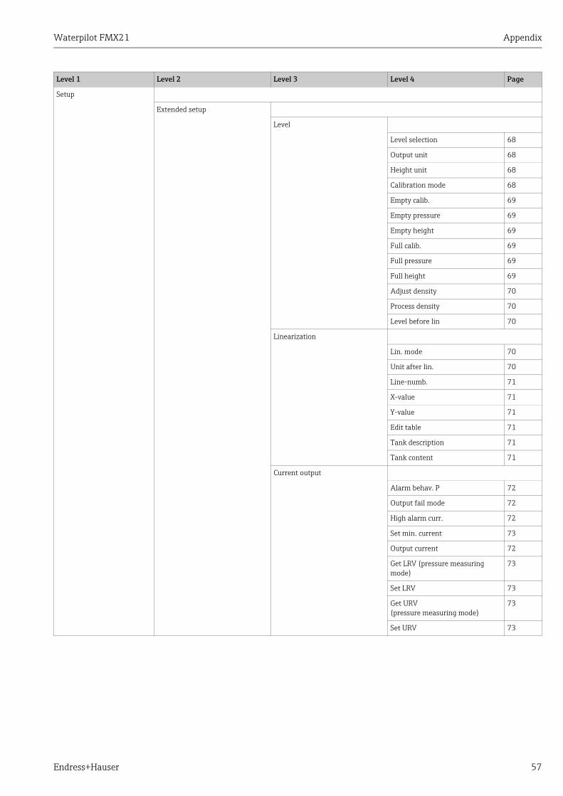
Waterpilot FMX21 Appendix
Endress+Hauser 57
Setup
Extended setup
Level
Level selection 68
Output unit 68
Height unit 68
Calibration mode 68
Empty calib. 69
Empty pressure 69
Empty height 69
Full calib. 69
Full pressure 69
Full height 69
Adjust density 70
Process density 70
Level before lin 70
Linearization
Lin. mode 70
Unit after lin. 70
Line-numb. 71
X-value 71
Y-value 71
Edit table 71
Tank description 71
Tank content 71
Current output
Alarm behav. P 72
Output fail mode 72
High alarm curr. 72
Set min. current 73
Output current 72
Get LRV (pressure measuring mode)
73
Set LRV 73
Get URV (pressure measuring mode)
73
Set URV 73
Level 1 Level 2 Level 3 Level 4 Page

Appendix Waterpilot FMX21
58 Endress+Hauser
Diagnosis
Diagnostic code 77
Last diag. code 78
Min. meas. press. 77
Max. meas. press. 77
Diagnostic list
Diagnostic 1 78
Diagnostic 2 78
Diagnostic 3 78
Diagnostic 4 78
Diagnostic 5 78
Diagnostic 6 78
Diagnostic 7 78
Diagnostic 8 78
Diagnostic 9 78
Diagnostic 10 78
Event logbook
Last diag. 1 78
Last diag. 2 78
Last diag. 3 78
Last diag. 4 78
Last diag. 5 78
Last diag. 6 78
Last diag. 7 78
Last diag. 8 78
Last diag. 9 78
Last diag. 10 78
Instrument info
Firmware version 64
Serial number 64
Ext. order code 64
Order identifier 64
Cust. tag number 64
Device tag 64
ENP version 64
Config. counter 78
Lower range limit 72
URL sensor 72
Manufacturer ID 75
Device type code 75
Device revision 75
Level 1 Level 2 Level 3 Level 4 Page

Waterpilot FMX21 Appendix
Endress+Hauser 59
Diagnosis
Measured values
Level before lin 70
Tank content 71
Meas. pressure 67
Sensor pressure 67
Corrected press. 67
Pressure after damping 67
Sensor temp. 66
Simulation
Simulation mode 79
Sim. pressure 79
Sim. level 79
Sim. tank cont. 79
Sim. current 79
Sim. alarm/warning 79
Enter reset code
Enter reset code 65
Expert
System
Code definition 64
Operator code 64
Instrument info
Cust. tag number 64
Device tag 64
Serial number 64
Firmware version 64
Ext. order code 64
Order identifier 64
ENP version 64
Electr. serial no. 64
Sensor serial no. 64
Management
Enter reset code 65
Level 1 Level 2 Level 3 Level 4 Page

Appendix Waterpilot FMX21
60 Endress+Hauser
Expert
Measurement
Measuring mode 65
Basic setup
Pos. zero adjust 66
Calib. offset 66
Damping value 66
Press. eng. unit 66
Temp. eng. unit 66
Sensor temp. 66
Pressure
Set LRV 67
Set URV 67
Meas. pressure 67
Sensor pressure 67
Corrected press. 67
Pressure after damping 67
Level
Level selection 68
Output unit 68
Height unit 68
Calibration mode 68
Empty calib. 69
Empty pressure 69
Empty height 69
Full calib. 69
Full pressure 69
Full height 69
Density unit 69
Adjust density 70
Process density 70
Level before lin 70
Linearization
Lin. mode 70
Unit after lin. 70
Line-numb. 71
X-value 71
Y-value 71
Edit table 71
Tank description 71
Tank content 71
Level 1 Level 2 Level 3 Level 4 Page

Waterpilot FMX21 Appendix
Endress+Hauser 61
Expert
Measurement
Sensor limits
Lower range limit 72
URL sensor 72
Sensor trim
Lo trim measured 72
Hi Trim measured value 72
Lo Trim sensor 72
Hi Trim sensor 72
Output
Current output
Output current 72
Alarm behavior 72
Output fail mode 72
High alarm curr. 72
Set min. current 73
Get LRV (pressure measuring mode)
73
Set LRV 73
Get URV (pressure measuring mode)
73
Set URV 73
Start current 73
Curr. trim 4mA 73
Curr. trim 20mA 74
Offset trim 4mA 74
Offset trim 20 mA 74
Communication
HART config.
Burst mode 74
Burst option 74
Current mode 74
Bus address 74
Preamble number 75
HART info
Device type code 75
Device revision 75
Manufacturer ID 75
HART version 75
Description 75
HART message 75
HART date 75
Level 1 Level 2 Level 3 Level 4 Page

Appendix Waterpilot FMX21
62 Endress+Hauser
Expert
Communication
HART output
Primary value is 75
Primary value 75
Secondary val. is 75
Secondary value 75
Third value is 75
Third value 76
4th value is 76
4th value 76
HART input
HART input value 76
HART input stat. 76
HART input unit 76
HART input form. 76
Application
Electr. delta P 76
Fixed ext. value 77
Auto dens. corr. 77
Diagnosis
Diagnostic code 77
Last diag. code 77
Reset logbook 77
Min. meas. press. 77
Max. meas. press. 77
Reset peakhold 77
Operating hours 78
Config. counter 78
Diagnostic list
Diagnostic 1 78
Diagnostic 2 78
Diagnostic 3 78
Diagnostic 4 78
Diagnostic 5 78
Diagnostic 6 78
Diagnostic 7 78
Diagnostic 8 78
Diagnostic 9 78
Diagnostic 10 78
Level 1 Level 2 Level 3 Level 4 Page

Waterpilot FMX21 Appendix
Endress+Hauser 63
Expert
Diagnosis
Event logbook
Last diag. 1 78
Last diag. 2 78
Last diag. 3 78
Last diag. 4 78
Last diag. 5 78
Last diag. 6 78
Last diag. 7 78
Last diag. 8 78
Last diag. 9 78
Last diag. 10 78
Simulation
Simulation mode 79
Sim. pressure 79
Sim. level 79
Sim. tank cont. 79
Sim. current 79
Sim. alarm/warning 79
Level 1 Level 2 Level 3 Level 4 Page

Appendix Waterpilot FMX21
64 Endress+Hauser
13.2 Description of parameters
This section describes the parameters in the order as they appear in the "Expert" operating menu in FieldCare.
13.2.1 System
Expert System
Expert System Instrument info
Parameter name Description
Operator codeEntry
Use this function to enter a code to lock or unlock operation.
Options: � To lock operation: enter a number the unlocking code.� To unlock operation: enter the unlocking code.
The release code is "0" in the order configuration. Another release code can be defined in the "Code definition" parameter.If the user has forgotten the release code, the release code will be visible and unlocked by entering the number "5864".
Factory setting:0
Code definitionEntry
Use this function to enter a release code with which the device can be unlocked.
Options: � A number between 0 and 9999
Factory setting:0
Parameter name Description
Cust. tag numberEntry
Enter device tag e.g. TAG number (max. 8 alphanumeric characters).
Factory setting:no entry or as per order specifications
Device tagEntry
Enter device tag e.g. TAG number (max. 32 alphanumeric characters).
Factory setting:no entry or as per order specifications
Serial numberDisplay
Displays the serial number of the device (11 alphanumeric characters).
Firmware versionDisplay
Displays the firmware version.
Ext. order codeEntry
Enter the extended order code.
Factory setting: as per order specifications
Order identifierEntry
Enter the order identifier.
Factory setting:as per order specifications
ENP versionDisplay
Displays the ENP version(ENP = electronic nameplate)
Electr. serial no. Display
Displays the serial number of the main electronics (11 alphanumeric characters).
Sensor serial no.Display
Displays the serial number of the sensor (11 alphanumeric characters).

Waterpilot FMX21 Appendix
Endress+Hauser 65
Expert System Management
13.2.2 Measurement
Expert Measurement
Parameter name Description
Enter reset codeEntry
Reset parameters completely or partially to the factory values or order configuration, ä 23, "Resetting to factory settings (reset)".
Factory setting:0
Parameter name Description
Measuring modeSelection
Select the measuring mode.The operating menu is structured differently depending on the measuring mode selected.
If the measuring mode is changed, no conversion takes place. The device has to be recalibrated or as per if the measuring mode is changed.
Options:� Pressure� Level
Factory setting:Pressure or as per order specifications

Appendix Waterpilot FMX21
66 Endress+Hauser
Expert Measurement Basic setup
Parameter name Description
Pos. zero adjust(relative pressure sensor)Selection
Position adjustment – the pressure difference between zero (set point) and the measured pressure need not be known.
Example:– Measured value = 2.2 mbar (0.033 psi)– You correct the measured value via the "Pos. zero adjust" parameter with the
"Confirm" option. This means that you assign the value 0.0 to the pressure present.
– Measured value (after pos. zero adjust) = 0.0 mbar– The current value is also corrected.
Options:� Confirm� Abort
Factory setting:Abort
Calib. offset (absolute pressure sensor)Entry
Position adjustment – the pressure difference between the set point and the measured pressure must be known.
Example:– Measured value = 982.2 mbar (15 psi)– You correct the measured value with the value entered (e.g. 2.2 mbar
(0.033 psi)) via the "Position offset" parameter. This means that you assign the value 980.0 (15 psi) to the pressure present.
– Measured value (after pos. zero adjust) = 980.0 mbar (15 psi)– The current value is also corrected.
Factory setting:0.0
Damping valueEntry
Enter damping time (time constant ). The damping affects the speed at which the measured value reacts to changes in pressure.
Input range:0.0 to 999.0 s
Factory setting:2.0 as per order specifications
Press. eng. unitSelection
Select the pressure unit.If a new pressure unit is selected, all pressure-specific parameters are converted and displayed with the new unit.
Options:� mbar, bar� mmH2O, mH2O, inH2O� ftH2O� Pa, kPa, MPa� psi� mmHg, inHg� kgf/cm2
Factory setting:mbar or bar depending on the sensor nominal measuring range, or as per order specifications
Temp. eng. unitSelection
Select the unit for the temperature measured values.
The setting affects the unit for the "Sensor temp." parameter.
Options:� °C� °F� K
Factory setting:°C
Sensor temp.Display
Displays the temperature currently measured in the sensor. This can deviate from the process temperature.
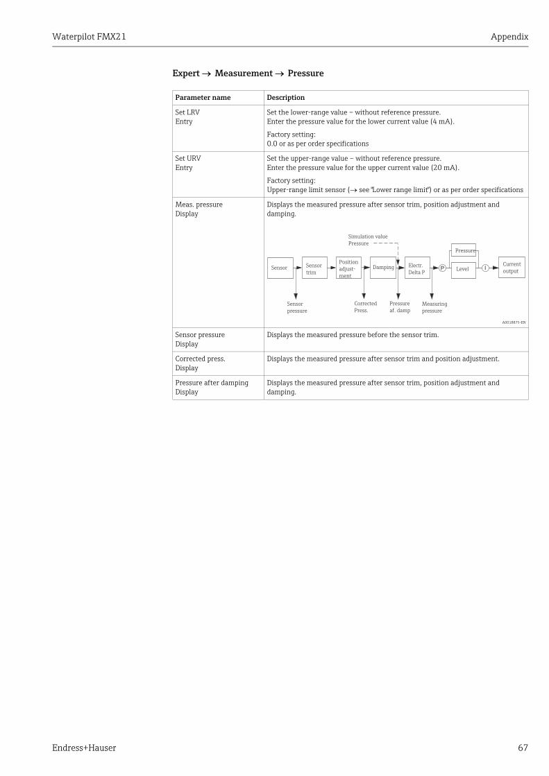
Waterpilot FMX21 Appendix
Endress+Hauser 67
Expert Measurement Pressure
Parameter name Description
Set LRVEntry
Set the lower-range value – without reference pressure.Enter the pressure value for the lower current value (4 mA).
Factory setting:0.0 or as per order specifications
Set URVEntry
Set the upper-range value – without reference pressure.Enter the pressure value for the upper current value (20 mA).
Factory setting:Upper-range limit sensor (see "Lower range limit") or as per order specifications
Meas. pressureDisplay
Displays the measured pressure after sensor trim, position adjustment and damping.
A0018875-EN
Sensor pressureDisplay
Displays the measured pressure before the sensor trim.
Corrected press.Display
Displays the measured pressure after sensor trim and position adjustment.
Pressure after dampingDisplay
Displays the measured pressure after sensor trim, position adjustment and damping.
P ISensorCurrent
output
Pressure
Level
Pressure
af. damp
Damping
Corrected
Press.
Position
adjust-
ment
Sensor
trim
Sensor
pressure
Simulation value
Pressure
Measuring
pressure
Electr.
Delta P

Appendix Waterpilot FMX21
68 Endress+Hauser
Expert Measurement Level
Parameter name Description
Level selectionSelection
Select the method for calculating the level
Options:� In pressure
If this option is selected, specify two pressure/level value pairs. The level value is displayed directly in the unit that you select via the "Output unit" parameter.
� In heightIf this option is selected, specify two height/level value pairs. From the measured pressure, the device first calculates the height using the density. This information is then used to calculate the level in the "Output unit" selected using the two value pairs specified.
Factory setting:In pressure
Output unitSelection
Select the unit for the measured value display for the level before linearization.
The unit selected is only used to describe the measured value. This means that the measured value is not converted when a new output unit is selected.
Example:� Current measured value: 0.3 ft� New output unit: m� New measured value: 0.3 m
Options:� %� mm, cm, dm, m� ft, inch� m3, in3
� l, hl� ft3
� gal, Igal� kg, t� lb
Factory setting:%
Height unitSelection
Select the height unit. The measured pressure is converted to the selected height unit using the "Adjust density" parameter.
Prerequisite:"Level selection" = "In height"
Options:� mm� m� inch� ft
Factory setting:m
Calibration modeSelection
Select the calibration mode.
Options:� Wet
Wet calibration takes place by filling and emptying the container. With two different levels, the level, volume, mass or percentage value entered is assigned to the pressure measured at this point in time ("Empty calibration" and "Full calibration" parameters).
� DryDry calibration is a theoretical calibration. For this calibration, you specify two pressure/level value pairs via the following parameters: "Empty calib.", "Empty pressure", "Full calib.", "Full pressure".
Factory setting:Wet

Waterpilot FMX21 Appendix
Endress+Hauser 69
Empty calib.Entry
Enter the output value for the lower calibration point (container empty). The unit defined in "Output unit" must be used.
In the case of wet calibration, the level (e.g. container empty or partially-filled) must actually be available. The associated pressure is then automatically recorded by the device. In the case of dry calibration, the level (container empty) does not have to be available. The associated pressure has to be entered in the "Empty pressure" parameter for the "In pressure" level selection. The associated height has to be entered in the "Empty height" parameter for the "In height" level selection.
Factory setting:0.0
Empty pressureEntry/display
Enter the pressure value for the lower calibration point (container empty).See also "Empty calib.".
Prerequisite� "Level selection" = "In pressure"
"Calibration mode" = Wet (display only), Dry (entry)
Factory setting:0.0
Empty heightEntry/display
Enter the height value for the lower calibration point (container empty). Select the unit via the "Height unit" parameter.
Prerequisite:� "Level selection" = In height
"Calibration mode" = Wet (display only), Dry (entry)
Factory setting:0.0
Full calib.Entry
Enter the output value for the upper calibration point (container full).
The unit defined in "Output unit" must be used.In the case of wet calibration, the level (e.g. container full or partially-filled) must actually be available. The associated pressure is then automatically recorded by the device. In the case of dry calibration, the level (container full) does not have to be available. The associated pressure has to be entered in the "Full pressure" parameter for the "In pressure" level mode. The associated height has to be entered in the "Empty height" parameter for the "In height" level selection.
Factory setting:100.0
Full pressureEntry/display
Enter the pressure value for the upper calibration point (container full).See also "Empty calib.".
Prerequisite� "Level selection" = In pressure
"Calibration mode" = Wet (display only), Dry (entry)
Factory setting:Upper-range limit (URL) of the sensor
Full heightEntry/display
Enter the height value for the upper calibration point (container full). Select the unit via the "Height unit" parameter.
Prerequisite:� "Level selection" = In height
"Calibration mode" = Wet (display only), Dry (entry)
Factory setting:Upper-range limit (URL) is converted to a height unit
Density unitDisplay
Displays the density unit. The measured pressure is converted to a height using the "Height unit" and "Adjust density" parameters.
Setting:� g/cm3
Parameter name Description

Appendix Waterpilot FMX21
70 Endress+Hauser
Expert Measurement Linearization
Adjust densityEntry/display
Enter the density of the medium. The measured pressure is converted to a height using the "Height unit" and "Adjust density" parameters.
User input:� Auto dens. corr. = Off
Display:� Auto dens. corr. Off
Factory setting:1.0
Process densityEntry/display
Enter a new density value for density correction.The calibration was carried out with water as the medium, for example. Now the container is to be used for another medium with another density. The calibration is corrected appropriately by entering the new density value in the "Process density" parameter.
If you change to dry calibration after a wet calibration via the "Calibration mode" parameter, the density must be entered for the "Adjust density" and "Process density" parameters before you switch calibration mode.
User input:� Auto dens. corr. = Off
Display:� Auto dens. corr. Off
Factory setting:1.0
Level before linDisplay
Displays the level value prior to linearization.
Parameter name Description
Lin. modeSelection
Select the linearization mode.
Options:� Linear:
The level is output without being converted beforehand. "Level before lin." is output.
� Erase table:The existing linearization table is deleted.
� Manual entry (sets the table to the edit mode, an alarm is output): The value pairs of the table (X-value and Y-value) are entered manually.
� Semiautomatic entry (sets the table to the edit mode, an alarm is output): The container is emptied or filled gradually in this entry mode. The device automatically records the level value (X-value). The associated volume, mass or %-value is entered manually (Y-value).
� Activate tableThe table entered is activated and checked with this option. The device shows the level after linearization.
Factory setting:Linear
Unit after lin.Selection
Select the volume unit (unit of the Y-value).
Options:� %� cm, dm, m, mm� hl� in3, ft3, m3
� l� in, ft� kg, t� lb� gal� Igal
Factory setting:%
Parameter name Description

Waterpilot FMX21 Appendix
Endress+Hauser 71
Line-numb.Entry
Enter the number of the current point in the table.The subsequent entries for "X-value" and "Y-value" refer to this point.
Input range:� 1 to 32
X-valueDisplay/entry
Enter the level value for the specific point in the table and confirm.
If "Lin. mode" = "Manual", the level value has to be entered.If "Lin. mode" = "Semiautomatic" the level value is displayed and has to be confirmed by entering the associated Y-value.
Y-valueEntry
Enter the output value for the specific point in the table.The unit is determined by "Unit after lin.".
The linearization table must be monotonic (monotonic increasing or decreasing).
Edit tableSelection
Select the function for entering the table.
Options:� Next point: enter the next point.� Current point: stay on the current point to correct a mistake for example.� Previous point: skip back to the previous point to correct a mistake for example.� Insert point: insert an additional point (see example below).� Delete point: delete the current point (see example below).
Example: Add a point - in this case between the 4th and 5th point for example– Select point 5 via the "Line-numb." parameter.– Select the "Enter point" option via the "Edit table" parameter.– Point 5 is displayed for the "Line-numb." parameter. Enter new values for the "X-
value" and "Y-value" parameters.
Example: Delete a point - in this case the 5th point for example– Select point 5 via the "Line-numb." parameter.– Select the "Delete point" option via the "Edit table" parameter.– The 5th point is deleted. All of the subsequent points are moved up one number
i.e. following deletion, the 6th point becomes Point 5.
Factory setting:current point
Tank descriptionEntry
Enter the tank description (max. 32 alphanumeric characters)
Tank contentDisplay
Displays the level value after linearization.
Parameter name Description

Appendix Waterpilot FMX21
72 Endress+Hauser
Expert Measurement Sensor limits
Expert Measurement Sensor trim
13.2.3 Current output
Expert Output Current output
Parameter name Description
Lower range limitDisplay
Displays the lower-range limit of the sensor.
URL sensorDisplay
Displays the upper-range limit of the sensor.
Parameter name Description
Lo trim measuredDisplay
Displays the reference pressure present to be accepted for the lower calibration point.
Hi trim measured Display
Displays the reference pressure present to be accepted for the upper calibration point.
Lo trim sensorEntry
Sensor recalibration by entering a target pressure while simultaneously and automatically accepting a reference pressure present for the lower calibration point.
Hi trim sensorEntry
Sensor recalibration by entering a target pressure while simultaneously and automatically accepting a reference pressure present for the upper calibration point.
Parameter name Description
Output currentDisplay
Displays the current value of the current.
Alarm behav. P Selection
Configure the current output for when the sensor limits are undershot or overshot.
Options: � Warning
The device continues measuring. An error message is displayed.� Alarm
The output signal assumes a value that can be specified by the "Output fail mode" function.
Factory setting:Warning
Output fail modeSelection
Select the output fail mode.In the event of an alarm, the current assumes the current value specified with this parameter.
Options: � Max: can be set from 21 and 23 mA see also "High alarm curr."� Hold: last measured value is held.� Min: 3.6 mA
Factory setting:Max
High alarm curr.Entry
Enter the current value for the high alarm current.See also "Output fail mode".
Input range:21 to 23 mA
Factory setting:22 mA

Waterpilot FMX21 Appendix
Endress+Hauser 73
Set min. currentEntry
Enter the lower current limiting value.Some switching units do not accept current values lower than 4.0 mA.
Options: � 3.8 mA� 4.0 mA
Factory setting:3.8 mA
Get LRVEntry
Set the lower-range value – reference pressure is present at the device.The pressure for the lower current value (4 mA) is present at the device. With the "Confirm" option, you assign the lower current value to the pressure value present.
Prerequisite:pressure measuring mode
Options:� Abort� Confirm
Factory setting:Abort
Set LRV Entry
Set the measure value for the lower current value (4 mA).
Factory setting:0.0 (%) in the level measuring mode; 0.0 or in accordance with ordering specifications in the pressure measuring mode
Get URVEntry
Set the upper-range value – reference pressure is present at the device.The pressure for the upper current value (20 mA) is present at the device. With the "Confirm" option, you assign the upper current value to the pressure value present.
Prerequisite:pressure measuring mode
Options:� Abort� Confirm
Factory setting:Abort
Set URVEntry
Set the measure value for the upper current value (20 mA).
Factory setting:100.0 (%) in the level measuring mode; URL sensor or in accordance with ordering information in the pressure measuring mode.
StartcurrentEntry
Use this function to enter the start current.This setting affects the HART Multidrop mode as well.
Options: � Min. alarm � 12 mA
Factory setting:12 mA
Curr. trim 4mAEntry
Enter the current value for the lower point (4 mA) of the current linear regression line.You can adapt the current output to the transmission conditions with this parameter and "Curr. trim 20mA".
Perform the current trim for the upper point as follows:
1. Select the "Current" option in the "Simulation mode" parameter.
2. Set the 4 mA value in the "Sim. current" parameter.
3. Enter the current value measured with the switching unit in the "Curr. trim 4mA" parameter.
Input range:Measured current ±0.2 mA
Factory setting:4 mA
Parameter name Description
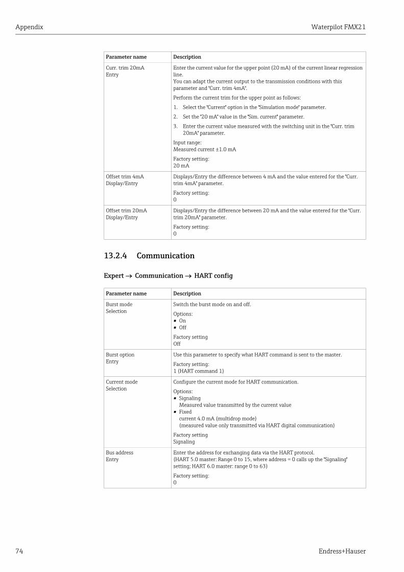
Appendix Waterpilot FMX21
74 Endress+Hauser
13.2.4 Communication
Expert Communication HART config
Curr. trim 20mA Entry
Enter the current value for the upper point (20 mA) of the current linear regression line.You can adapt the current output to the transmission conditions with this parameter and "Curr. trim 4mA".
Perform the current trim for the upper point as follows:
1. Select the "Current" option in the "Simulation mode" parameter.
2. Set the "20 mA" value in the "Sim. current" parameter.
3. Enter the current value measured with the switching unit in the "Curr. trim 20mA" parameter.
Input range:Measured current ±1.0 mA
Factory setting:20 mA
Offset trim 4mA Display/Entry
Displays/Entry the difference between 4 mA and the value entered for the "Curr. trim 4mA" parameter.
Factory setting:0
Offset trim 20mA Display/Entry
Displays/Entry the difference between 20 mA and the value entered for the "Curr. trim 20mA" parameter.
Factory setting:0
Parameter name Description
Burst mode Selection
Switch the burst mode on and off.
Options: � On� Off
Factory settingOff
Burst option Entry
Use this parameter to specify what HART command is sent to the master.
Factory setting:1 (HART command 1)
Current mode Selection
Configure the current mode for HART communication.
Options:� Signaling
Measured value transmitted by the current value� Fixed
current 4.0 mA (multidrop mode)(measured value only transmitted via HART digital communication)
Factory settingSignaling
Bus address Entry
Enter the address for exchanging data via the HART protocol. (HART 5.0 master: Range 0 to 15, where address = 0 calls up the "Signaling" setting; HART 6.0 master: range 0 to 63)
Factory setting:0
Parameter name Description

Waterpilot FMX21 Appendix
Endress+Hauser 75
Expert Communication HART info
Expert Communication HART output
Preamble number Entry
Enter the number of preambles in the HART protocol. (Synchronization of the modem modules along a transmission path, each modem module could "swallow" one byte; at least 2 bytes must arrive at the end.)
Input range:2 to 20
Factory setting:5
Parameter name Description
Device type code Display
Displays the numeric ID of the device.For Waterpilot FMX21: 36
Device revision Display
Displays the device revision.e.g.: 1
Manufacturer ID Display
Displays the manufacturer number in decimal numerical format.Here: 17 (Endress+Hauser)
HART revision Display
Displays the HART revision.Here: 6
Description Entry
Enter the tag description (max. 16 alphanumeric characters).
HART message Entry
Enter a message (max. 32 alphanumeric characters). This message is sent via the HART protocol at the request of the master.
HART date Entry
Enter the date of the last change in configuration.
Factory setting:DD/MM/YY (date of the final test)
Parameter name Description
Primary value isDisplay
Indicates which measured variable is transmitted as the primary process value via the HART protocol.The variable displayed depends on the "measuring mode" selected:– Pressure measuring mode: "Meas. pressure"– Level measuring mode "Linear" lin. mode: "Level before lin."– Level measuring mode "Activate table" lin. mode: "Tank content"
Primary valueDisplay
Displays the primary process value.
Secondary val. isDisplay
Indicates which measured variable is transmitted as the secondary process value via the HART protocol.
The following process values can be displayed depending on the measuring mode selected:– "Meas. pressure"– "Sensor pressure"– "Corrected press."– "Pressure after damping"– "Sensor temp."– "Level before lin"– "Tank content"– "Process density" (corrected)
Secondary valueDisplay
Displays the secondary process value.
Third value isDisplay
Indicates which measured variable is transmitted as the third process value via the HART protocol.The variable displayed depends on the "measuring mode" selected. See the list for "Secondary val. is"
Parameter name Description

Appendix Waterpilot FMX21
76 Endress+Hauser
Expert Communication HART input
13.2.5 Application
Expert Application
Third valueDisplay
Displays the third process value.
Fourth value isDisplay
Indicates which measured variable is transmitted as the fourth process value via the HART protocol.The variable displayed depends on the "measuring mode" selected. See the list for "Secondary val. is"
4th valueDisplay
Displays the fourth process value.
Parameter name Description
HART input valueDisplay
Displays the HART input value.
HART input stat.Display
Displays the HART input statusBad / Uncertain / Good
HART input unitSelection
Select the HART input value.
Options:� Unknown� mbar, bar� mmH2O, ftH2O, inH2O� Pa, hPa, kPa, MPa� psi� mmHg, inHg� Torr� g/cm2, kg/cm2
� lb/ft2
� atm� °C, °F, K, RFactory setting:unknown
HART input form.Selection
Specify the format for displaying the HART input value.
Options:� x.x (default)� x.xx� x.xxx� x.xxxx� x.xxxxx
Factory setting:x.x
Parameter name Description
Electr. delta PEntry
For switching the electr. delta P application on or off with an external or constant value.
Options:OffExternal valueConstant
Factory setting:Off
Parameter name Description
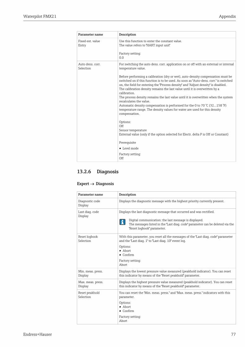
Waterpilot FMX21 Appendix
Endress+Hauser 77
13.2.6 Diagnosis
Expert Diagnosis
Fixed ext. valueEntry
Use this function to enter the constant value.The value refers to "HART input unit"
Factory setting:0.0
Auto dens. corr.Selection
For switching the auto dens. corr. application on or off with an external or internal temperature value.
Before performing a calibration (dry or wet), auto-density compensation must be switched on if this function is to be used. As soon as "Auto-dens. corr." is switched on, the field for entering the "Process density" and "Adjust density" is disabled. The calibration density remains the last value until it is overwritten by a calibration. The process density remains the last value until it is overwritten when the system recalculates the value.Automatic density compensation is performed for the 0 to 70 °C (32...158 °F) temperature range. The density values for water are used for this density compensation.
Options:OffSensor temperatureExternal value (only if the option selected for Electr. delta P is Off or Constant)
Prerequisite
� Level mode
Factory setting:Off
Parameter name Description
Diagnostic codeDisplay
Displays the diagnostic message with the highest priority currently present.
Last diag. codeDisplay
Displays the last diagnostic message that occurred and was rectified.
Digital communication: the last message is displayed. The messages listed in the "Last diag. code" parameter can be deleted via the "Reset logbook" parameter.
Reset logbook Selection
With this parameter, you reset all the messages of the "Last diag. code" parameter and the "Last diag. 1" to "Last diag. 10" event log.
Options: � Abort� Confirm
Factory setting:Abort
Min. meas. press.Display
Displays the lowest pressure value measured (peakhold indicator). You can reset this indicator by means of the "Reset peakhold" parameter.
Max. meas. press.Display
Displays the highest pressure value measured (peakhold indicator). You can reset this indicator by means of the "Reset peakhold" parameter.
Reset peakholdSelection
You can reset the "Min. meas. press." and "Max. meas. press." indicators with this parameter.
Options: � Abort� Confirm
Factory setting:Abort
Parameter name Description
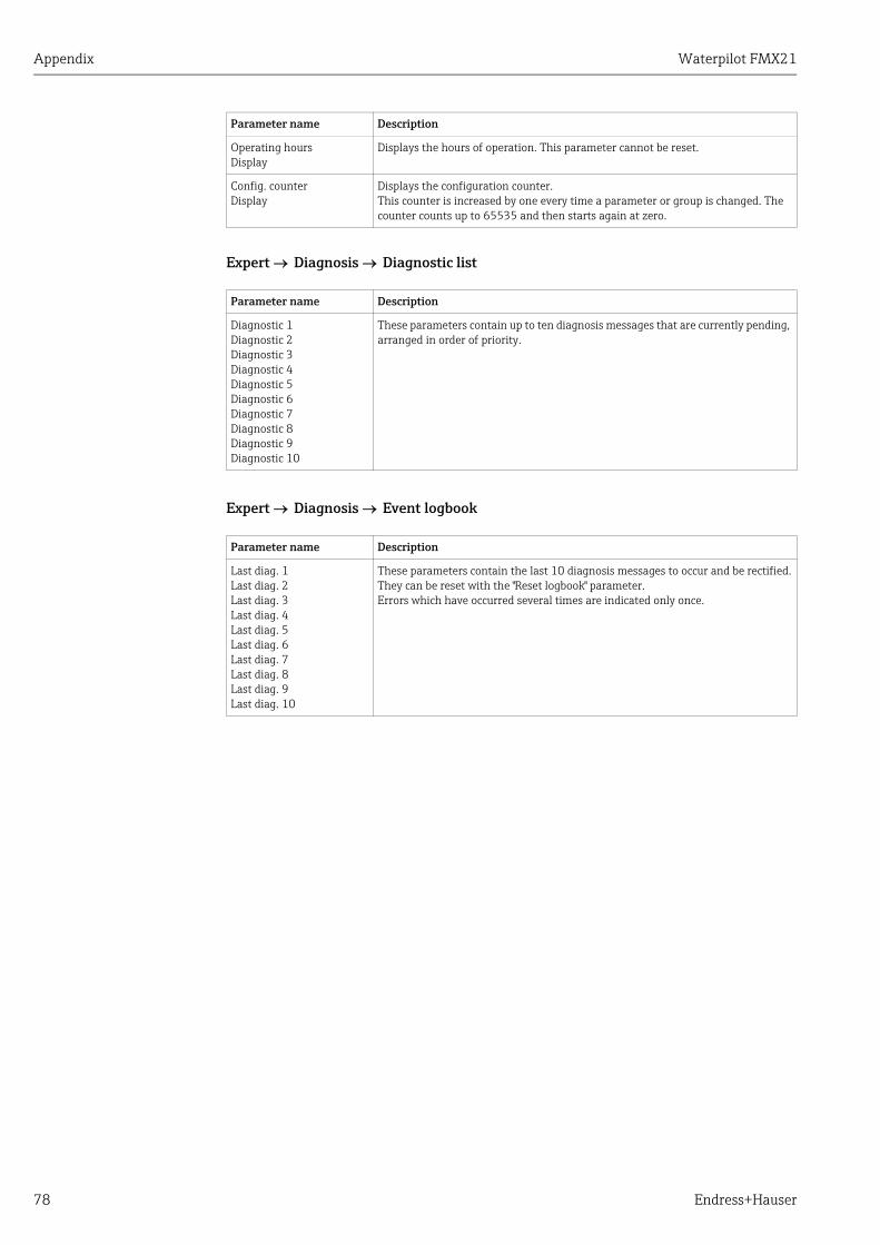
Appendix Waterpilot FMX21
78 Endress+Hauser
Expert Diagnosis Diagnostic list
Expert Diagnosis Event logbook
Operating hoursDisplay
Displays the hours of operation. This parameter cannot be reset.
Config. counterDisplay
Displays the configuration counter.This counter is increased by one every time a parameter or group is changed. The counter counts up to 65535 and then starts again at zero.
Parameter name Description
Diagnostic 1 Diagnostic 2 Diagnostic 3 Diagnostic 4 Diagnostic 5 Diagnostic 6 Diagnostic 7 Diagnostic 8 Diagnostic 9 Diagnostic 10
These parameters contain up to ten diagnosis messages that are currently pending, arranged in order of priority.
Parameter name Description
Last diag. 1Last diag. 2 Last diag. 3 Last diag. 4 Last diag. 5 Last diag. 6 Last diag. 7 Last diag. 8 Last diag. 9 Last diag. 10
These parameters contain the last 10 diagnosis messages to occur and be rectified.They can be reset with the "Reset logbook" parameter.Errors which have occurred several times are indicated only once.
Parameter name Description

Waterpilot FMX21 Appendix
Endress+Hauser 79
Expert Diagnosis Simulation
Parameter name Description
Simulation modeSelection
Switch on simulation and select the simulation mode. Any simulation running is switched off if the measuring mode or level selection ("in pressure" or "in height" is changed.
Option: � None � Pressure see also this table, "Sim. pressure" parameter� Level see this table, "Sim. level" parameter� Tank content see this table, "Sim. tank cont." parameter� Current see this table, "Sim. current" parameter� Alarm/warning see this table, "Sim. error no." parameter
A0019168-EN
Factory setting:None
Sim. pressure Entry
Enter the simulation value. See also "Simulation mode".
Prerequisite:� "Simulation mode" = Pressure
Factory setting:Current pressure measured value
Sim. levelEntry
Enter the simulation value. See also "Simulation mode".
Prerequisite:� "Measuring mode" = Level and "Simulation mode" = Level
Sim. tank cont.Entry
Enter the simulation value. See also "Simulation mode".
Prerequisites:� "Measuring mode" = Level, "Activate table" lin. mode and "Simulation mode" =
Tank content.
Sim. currentEntry
Enter the simulation value. See also "Simulation mode".
Prerequisite:� "Simulation mode"= Current value
Factory setting:Current value of the current
Sim. alarm/warningEntry
Enter the diagnostic message number.See also "Simulation mode".
Prerequisite:� "Simulation mode"= Alarm/warning
Factory setting:484 (simulation active)
P PV
Simulation value pressure
Transducer Block
–Simulation value level–
Sensor Currentoutput
Pressure
LevelDampingPositionadjust-ment
Sensortrim
Sim.current
Simulation value tank content

Appendix Waterpilot FMX21
80 Endress+Hauser
Waterpilot FMX21
Endress+Hauser 81
Index
AAccessories . . . . . . . . . . . . . . . . . . . . . . . . . . . . . . . . . . . . . 52Additional weight . . . . . . . . . . . . . . . . . . . . . . . . . . . . . . . 53Adjust density . . . . . . . . . . . . . . . . . . . . . . . . . . . . . . . . . . 70Alarm behavior . . . . . . . . . . . . . . . . . . . . . . . . . . . . . . . . . 72Auto dens. corr. . . . . . . . . . . . . . . . . . . . . . . . . . . . . . . . . . 77
BBasic settings . . . . . . . . . . . . . . . . . . . . . . . . . . . . . . . . . . . 25Burst mode . . . . . . . . . . . . . . . . . . . . . . . . . . . . . . . . . . . . . 74Burst option . . . . . . . . . . . . . . . . . . . . . . . . . . . . . . . . . . . . 74Bus address. . . . . . . . . . . . . . . . . . . . . . . . . . . . . . . . . . . . . 74
CCable marking . . . . . . . . . . . . . . . . . . . . . . . . . . . . . . . . . . 54Cable specification . . . . . . . . . . . . . . . . . . . . . . . . . . . . . . . 16Calibration mode . . . . . . . . . . . . . . . . . . . . . . . . . . . . . . . . 68Code definition. . . . . . . . . . . . . . . . . . . . . . . . . . . . . . . 23, 64Config. counter. . . . . . . . . . . . . . . . . . . . . . . . . . . . . . . . . . 78Configuring the damping . . . . . . . . . . . . . . . . . . . . . . . . . 26Connecting Commubox FXA195 . . . . . . . . . . . . . . . . . . . 19Connecting Field Xpert SFX . . . . . . . . . . . . . . . . . . . . . . . 19Connecting the device . . . . . . . . . . . . . . . . . . . . . . . . . . . . 14Connection data . . . . . . . . . . . . . . . . . . . . . . . . . . . . . . . . . 15Corrected press. . . . . . . . . . . . . . . . . . . . . . . . . . . . . . . . . . 67Curr. trim 20mA . . . . . . . . . . . . . . . . . . . . . . . . . . . . . . . . 74Curr. trim 4mA. . . . . . . . . . . . . . . . . . . . . . . . . . . . . . . . . . 73Current consumption . . . . . . . . . . . . . . . . . . . . . . . . . . . . 16Current mode . . . . . . . . . . . . . . . . . . . . . . . . . . . . . . . . . . . 74
DDamping value . . . . . . . . . . . . . . . . . . . . . . . . . . . . . . . . . . 66Density unit . . . . . . . . . . . . . . . . . . . . . . . . . . . . . . . . . . . . 69Description . . . . . . . . . . . . . . . . . . . . . . . . . . . . . . . . . . . . . 75Device revision . . . . . . . . . . . . . . . . . . . . . . . . . . . . . . . . . . 75Device tag . . . . . . . . . . . . . . . . . . . . . . . . . . . . . . . . . . . . . . 64Device type code. . . . . . . . . . . . . . . . . . . . . . . . . . . . . . . . . 75Diagnostic . . . . . . . . . . . . . . . . . . . . . . . . . . . . . . . . . . . . . . 78Diagnostic code . . . . . . . . . . . . . . . . . . . . . . . . . . . . . . . . . 77
EEdit table. . . . . . . . . . . . . . . . . . . . . . . . . . . . . . . . . . . . . . . 71Electr. delta P . . . . . . . . . . . . . . . . . . . . . . . . . . . . . . . . . . . 76Electr. serial no. . . . . . . . . . . . . . . . . . . . . . . . . . . . . . . . . . 64Empty calib. . . . . . . . . . . . . . . . . . . . . . . . . . . . . . . . . . . . . 69Empty height . . . . . . . . . . . . . . . . . . . . . . . . . . . . . . . . . . . 69Empty pressure . . . . . . . . . . . . . . . . . . . . . . . . . . . . . . . . . 69ENP version . . . . . . . . . . . . . . . . . . . . . . . . . . . . . . . . . . . . 64Enter reset code . . . . . . . . . . . . . . . . . . . . . . . . . . . . . . . . . 65Ext. order code . . . . . . . . . . . . . . . . . . . . . . . . . . . . . . . . . . 64
FFactory setting . . . . . . . . . . . . . . . . . . . . . . . . . . . . . . . . . . 23FieldCare. . . . . . . . . . . . . . . . . . . . . . . . . . . . . . . . . . . . . . . 22Firmware version. . . . . . . . . . . . . . . . . . . . . . . . . . . . . . . . 64Fixed ext. value . . . . . . . . . . . . . . . . . . . . . . . . . . . . . . . . . 77Full calib.. . . . . . . . . . . . . . . . . . . . . . . . . . . . . . . . . . . . . . . 69
Full height . . . . . . . . . . . . . . . . . . . . . . . . . . . . . . . . . . . . . . 69Full pressure . . . . . . . . . . . . . . . . . . . . . . . . . . . . . . . . . . . . 69
GGet LRV. . . . . . . . . . . . . . . . . . . . . . . . . . . . . . . . . . . . . . . . . 73Get URV . . . . . . . . . . . . . . . . . . . . . . . . . . . . . . . . . . . . . . . . 73
HHART config. . . . . . . . . . . . . . . . . . . . . . . . . . . . . . . . . . . . . 74HART date . . . . . . . . . . . . . . . . . . . . . . . . . . . . . . . . . . . . . . 75HART input . . . . . . . . . . . . . . . . . . . . . . . . . . . . . . . . . . . . . 76HART input form. . . . . . . . . . . . . . . . . . . . . . . . . . . . . . . . . 76HART input stat. . . . . . . . . . . . . . . . . . . . . . . . . . . . . . . . . . 76HART input unit . . . . . . . . . . . . . . . . . . . . . . . . . . . . . . . . . 76HART input value . . . . . . . . . . . . . . . . . . . . . . . . . . . . . . . . 76HART message . . . . . . . . . . . . . . . . . . . . . . . . . . . . . . . . . . 75HART output . . . . . . . . . . . . . . . . . . . . . . . . . . . . . . . . . . . . 75HART revision . . . . . . . . . . . . . . . . . . . . . . . . . . . . . . . . . . . 75Height unit . . . . . . . . . . . . . . . . . . . . . . . . . . . . . . . . . . . . . . 68Hi trim measured . . . . . . . . . . . . . . . . . . . . . . . . . . . . . . . . 72Hi trim sensor . . . . . . . . . . . . . . . . . . . . . . . . . . . . . . . . . . . 72High alarm curr. . . . . . . . . . . . . . . . . . . . . . . . . . . . . . . . . . 72
IIncoming acceptance and product identification. . . . . . . . 6Installation . . . . . . . . . . . . . . . . . . . . . . . . . . . . . . . . . . . . . . . 9
LLast diag. code . . . . . . . . . . . . . . . . . . . . . . . . . . . . . . . . . . . 77Last diagnostic. . . . . . . . . . . . . . . . . . . . . . . . . . . . . . . . . . . 78Level before lin . . . . . . . . . . . . . . . . . . . . . . . . . . . . . . . . . . 70Level measurement. . . . . . . . . . . . . . . . . . . . . . . . . . . . . . . 29Level selection . . . . . . . . . . . . . . . . . . . . . . . . . . . . . . . . . . . 68Lin. mode . . . . . . . . . . . . . . . . . . . . . . . . . . . . . . . . . . . . . . . 70Linearization . . . . . . . . . . . . . . . . . . . . . . . . . . . . . . . . . . . . 44Line-numb.. . . . . . . . . . . . . . . . . . . . . . . . . . . . . . . . . . . . . . 71Lo trim measured . . . . . . . . . . . . . . . . . . . . . . . . . . . . . . . . 72Lo trim sensor . . . . . . . . . . . . . . . . . . . . . . . . . . . . . . . . . . . 72Load . . . . . . . . . . . . . . . . . . . . . . . . . . . . . . . . . . . . . . . . . . . 17Locking . . . . . . . . . . . . . . . . . . . . . . . . . . . . . . . . . . . . . . . . . 23Lower range limit . . . . . . . . . . . . . . . . . . . . . . . . . . . . . . . . 72
MManufacturer ID . . . . . . . . . . . . . . . . . . . . . . . . . . . . . . . . . 75Max. meas. press. . . . . . . . . . . . . . . . . . . . . . . . . . . . . . . . . 77Meas. pressure. . . . . . . . . . . . . . . . . . . . . . . . . . . . . . . . . . . 67Measuring mode . . . . . . . . . . . . . . . . . . . . . . . . . . . . . 25, 65Min. meas. press. . . . . . . . . . . . . . . . . . . . . . . . . . . . . . . . . 77Mounting the extension cable mounting screw . . . . . . . 11Mounting the mounting clamp . . . . . . . . . . . . . . . . . . . . . 10Mounting the terminal box . . . . . . . . . . . . . . . . . . . . . . . . 12Mounting the TMT182 temperature transmitter . . . . . . 12
NNameplate . . . . . . . . . . . . . . . . . . . . . . . . . . . . . . . . . . . . . . . 6

Waterpilot FMX21
82 Endress+Hauser
OOffset trim 20mA . . . . . . . . . . . . . . . . . . . . . . . . . . . . . . . . 74Offset trim 4mA . . . . . . . . . . . . . . . . . . . . . . . . . . . . . . . . . 74Operating hours . . . . . . . . . . . . . . . . . . . . . . . . . . . . . . . . . 78Operating menu . . . . . . . . . . . . . . . . . . . . . . . . . . . . . . . . . 56Operator code . . . . . . . . . . . . . . . . . . . . . . . . . . . . . . . 23, 64Order identifier . . . . . . . . . . . . . . . . . . . . . . . . . . . . . . . . . . 64Output current. . . . . . . . . . . . . . . . . . . . . . . . . . . . . . . . . . . 72Output fail mode. . . . . . . . . . . . . . . . . . . . . . . . . . . . . . . . . 72Output unit . . . . . . . . . . . . . . . . . . . . . . . . . . . . . . . . . . . . . 68Overvoltage protection. . . . . . . . . . . . . . . . . . . . . . . . . . . . 18
PPos. zero adjust . . . . . . . . . . . . . . . . . . . . . . . . . . . . . . . . . . 66Position adjustment . . . . . . . . . . . . . . . . . . . . . . . . . . . . . . 26Power consumption . . . . . . . . . . . . . . . . . . . . . . . . . . . . . . 16Preamble number . . . . . . . . . . . . . . . . . . . . . . . . . . . . . . . . 75Press. eng. unit . . . . . . . . . . . . . . . . . . . . . . . . . . . . . . 25, 66Pressure after damping . . . . . . . . . . . . . . . . . . . . . . . . . . . 67Pressure measurement . . . . . . . . . . . . . . . . . . . . . . . . . . . 27Process density . . . . . . . . . . . . . . . . . . . . . . . . . . . . . . . . . . 70Process value . . . . . . . . . . . . . . . . . . . . . . . . . . . . . . . . . . . . 75Product identification. . . . . . . . . . . . . . . . . . . . . . . . . . . . . . 6
RReset . . . . . . . . . . . . . . . . . . . . . . . . . . . . . . . . . . . . . . . . . . . 23Reset logbook . . . . . . . . . . . . . . . . . . . . . . . . . . . . . . . . . . . 77Reset peakhold . . . . . . . . . . . . . . . . . . . . . . . . . . . . . . . . . . 77Return. . . . . . . . . . . . . . . . . . . . . . . . . . . . . . . . . . . . . . . . . . 52
SSafety instructions . . . . . . . . . . . . . . . . . . . . . . . . . . . . . . . . 5Sensor pressure. . . . . . . . . . . . . . . . . . . . . . . . . . . . . . . . . . 67Sensor serial no. . . . . . . . . . . . . . . . . . . . . . . . . . . . . . . . . . 64Sensor temp. . . . . . . . . . . . . . . . . . . . . . . . . . . . . . . . . . . . . 66Serial number . . . . . . . . . . . . . . . . . . . . . . . . . . . . . . . . . . . 64Set LRV. . . . . . . . . . . . . . . . . . . . . . . . . . . . . . . . . . . . . 67, 73Set min. current . . . . . . . . . . . . . . . . . . . . . . . . . . . . . . . . . 73Set URV . . . . . . . . . . . . . . . . . . . . . . . . . . . . . . . . . . . . 67, 73Sim. current . . . . . . . . . . . . . . . . . . . . . . . . . . . . . . . . . . . . . 79Sim. error no.. . . . . . . . . . . . . . . . . . . . . . . . . . . . . . . . . . . . 79Sim. level . . . . . . . . . . . . . . . . . . . . . . . . . . . . . . . . . . . . . . . 79Sim. pressure . . . . . . . . . . . . . . . . . . . . . . . . . . . . . . . . . . . . 79Sim. tank cont. . . . . . . . . . . . . . . . . . . . . . . . . . . . . . . . . . . 79Simulation mode. . . . . . . . . . . . . . . . . . . . . . . . . . . . . . . . . 79Software history . . . . . . . . . . . . . . . . . . . . . . . . . . . . . . . . . 51Spare parts. . . . . . . . . . . . . . . . . . . . . . . . . . . . . . . . . . . . . . 52Start current . . . . . . . . . . . . . . . . . . . . . . . . . . . . . . . . . . . . 73Supply voltage . . . . . . . . . . . . . . . . . . . . . . . . . . . . . . . . . . . 16symbols and safety icons . . . . . . . . . . . . . . . . . . . . . . . . . . . 3
TTank content . . . . . . . . . . . . . . . . . . . . . . . . . . . . . . . . . . . . 71Tank description . . . . . . . . . . . . . . . . . . . . . . . . . . . . . . . . . 71Temp. eng. unit . . . . . . . . . . . . . . . . . . . . . . . . . . . . . . . . . . 66Transport . . . . . . . . . . . . . . . . . . . . . . . . . . . . . . . . . . . . . . . . 8Troubleshooting . . . . . . . . . . . . . . . . . . . . . . . . . . . . . . . . . 48
UUnit after lin. . . . . . . . . . . . . . . . . . . . . . . . . . . . . . . . . . . . . 70
Unlocking . . . . . . . . . . . . . . . . . . . . . . . . . . . . . . . . . . . . . . . 23URL sensor . . . . . . . . . . . . . . . . . . . . . . . . . . . . . . . . . . . . . . 72
XX-value . . . . . . . . . . . . . . . . . . . . . . . . . . . . . . . . . . . . . . . . . 71
YY-value . . . . . . . . . . . . . . . . . . . . . . . . . . . . . . . . . . . . . . . . . 71

Waterpilot FMX21
Endress+Hauser 83

www.addresses.endress.com
71205221