Operating Instructions - Ultrasonic Welding Solutions · 3 Note Before the machine is unpacked and...
67
Operating Instructions CUTTING STATION TYPE 3 BASE/TYPE 5 TABLE WITH A GENERATOR SL35 English
Transcript of Operating Instructions - Ultrasonic Welding Solutions · 3 Note Before the machine is unpacked and...

Operating Instructions
C U T T I N G S TAT I O N T Y P E 3 B A S E / T Y P E 5 TA B L E
W I T H A G E N E R AT O R S L 3 5
Engl
ish

Copyright by Rinco Ultrasonics AG, Switzerland
Version 2.0, gb, Art.-No. 34134
2

3
Note
Before the machine is unpacked and started up, theseoperating instructions must be read and their contentmust be observed when operating the machine. Themachine may only be operated, serviced and repairedby persons who are familiar with these operatinginstructions and the current statutory regulations forhealth and safety at work.
Specification Maschine3 21 1390 Typ 3Article: 31836Series: 1004Year: 2002
GeneratorSL 35 für 600 WArticle: 2772Series: 1898Year: 2002
Agency

Contents
1 Explanation of symbols and signs 7
2 Safety information 82.1 General 82.2 Intended purpose 82.3 Special points to note 82.4 Choosing staff 82.5 Installing the units 82.6 Operation 82.7 Noise emissions 92.8 Guarantee 9
3 Transportation 103.1 Unpacking/receiving inspection 103.2 Damage during transit 103.3 Positioning the plant 11
4 Product Information 124.1 Side view of cutting station 12
4.1.1 Cutting station 124.1.2 Ultrasonic generator 12
4.2 Examples for application 134.3 Using ultrasonics in the plastics 13
and synthetic fabrics industry4.4 Advantages of welding and cutting 14
with ultrasonic4.5 Cutting station functions and 14
characteristics4.6 Technical data of cutting station 15
4.6.1 Insert 154.6.2 Booster 154.6.3 Structure 154.6.4 Compressed air 154.6.5 Weight 15
4.7 Technical data of ultrasonic generator 164.7.1 Dimensions SL35 164.7.2 Concept 164.7.3 Available generator modules 174.7.4 Connected loads 174.7.5 Dimensions 17
5 Control and display elements 185.1 Pneumatic group 185.2 Vibration system 195.3 Anvil 195.4 Fixing axis of anvil 195.5 Fixing clamp of anvil 195.6 Support arm of anvil 195.7 Controls and indicators 20
6 Commissioning 226.1 Setting up 226.2 Space requirement 226.3 Preparing and connecting the unit 226.4 Fitting the vibration system6.5 Adjustments 266.6 Switching off 28
7 Operation 297.1 Sequence of welding process 29
7.1.1 Work cycle 297.1.2 Optimisation 317.1.3 Parameter setup 317.1.4 Description of setting 32
parameters7.2 Parameter set-up procedure 347.3 Automatic connection 35
8 Elements 368.1 Converter 368.2 Booster 378.3 Horn 38
8.3.1 Horn materials 398.4 Cutting table for work piece (anvil) 40
9 Replacement 419.1 Replacing the booster 419.2 Parameter initialization 47
9.2.1 Description of selectable 48functions
9.2.2 System initialization process 50
4

10 Cleaning and servicing 5210.1 General servicing tasks 5210.2 Vibration system and carriage 5210.3 Pneumatic group 5310.4 Generator 5310.5 Oscillating system 5410.6 Threaded coupling 54
11 Error messages and trouble shooting 5511.1 Error messages/corrective actions: 55
switching on11.2 Error messages and error elimination 55
during adjustments and welding11.3 Generator error messages 56
during operation
12 Electric wiring diagrams 5712.1 Wiring diagram for the SL generator 57
12.1.1 Operating element STO1 5712.1.2 Manual starter 58
STO2 (standard)12.1.3 Manual starter 58
STO2 (optional)12.1.4 Automatic start-up 59
STO2 (pedal)12.1.5 Interface STO3 60
12.2 Melting strips 6112.3 Listing of fuses 6212.4 Back part of generator SL35 6212.5 Listing of the connection terminals 62
of the unit
13 Technical drawings and dimensions 6313.1 Drawing of cutting station 6313.2 Amplitude values of the 64
GM generator module series13.3 Amplitude of SL generators
with 35 kHz 6413.4 Length of screws of the different 65
components of the vibration systemfor 35 kHz
14 Adresses of technical customer service 66
5

6
ImportantPlease quote the exact type designation and theunit serial numbers in all enquiries concering yourMultipress and your Generator.You will find this data on the rating plate (A) at theback of each unit, as well as on the inside coverflap of this operating manual.The design and circuitry of these units are subjectto continuous further development and improvement,and represent the latest state of the art.
RINCO ULTRASONICS AGRomanshorn, Schweiz
Preface
Congratulations on the purchase of your cuttingstation.The purpose of this manual is to give the purchaserand the user all the information they need in termsof the handling, assembly, operation and care ofthe cutting station.To ensure that your system is always in an operational state, you should take note of andfollow all the tips and instructions containedwithin this manual.
A

7
1 Explanation of symbols and signs
Special attention should be paid to passages withthe following symbols:
Special information or operating instructions.
Warnings regarding risk of personal injury ordamage to parts of the equipment.

8
2 Safety information
2.1 GeneralThe design of this unit conforms to the current stateof engineering and is safe to operate.The individual modules and the complete unit aresubject to continual inspection by our qualityassurance department.
2.2 Intended purposeThe unit is intended exclusively for the ultrasonicwelding of suitable plastics. Any other use isregarded as inconsistent with the intended purpose,and is undertaken at the user's own risk.The manufacturer is not liable for any resultantdamage. Intended for industrial use.
2.3 Special points to note• Before you start up the unit for the first time,
read this operation manual carefully.• Being badly informed about how to operate and
look after the generator can result in damage.• Always keep the operating manual handy at the
site of the unit.• Do not perform any modifications, extensions
or conversions on the unit which might endangersafety without the supplier's consent.
• Do not alter the programming (software) ofprogrammable control systems.
2.4 Choosing staffWork on the electrical installations of the unit mayonly be performed by an electrical specialist orinstructed staff under the management and super-vision of an electrical specialist, according toelectrical engineering standards.
2.5 Installing the units
Always unplug the power cable before making anyconnections to peripheral units.Be sure to fit the power supply with a grounding connector!Observe any statutory safety regulations in force inyour country!Failure to observe these regulations will exempt themanufacturer from all liability for injury to persons ordamage to materials!Before starting up the unit, always make sure it is ina closed and safe condition.
2.6 Operation
Never open the generator or converter housing whilethe Multipress is in operation.There is a high voltage inside the units – risk of injury!
Avoid any potentially unsafe working practices.Correct operation and careful handling of the unitsand their associated tools during operation will• keep the system ready for service,• prolong its useful life, and• reduce stoppage times to a minimum.
!

9
2.7 Noise emissions
Caution!Limits: Ultrasonic does not cause any damageaccording to present scientific research as long asthe maximum noise level remains below 140 dB andthe average level, assuming an 8h/day, remainsbelow 110 dB.
Keep an eye on the sub harmonic i.e. audiblefrequencies, which fluctuate depending on applica-tion and are annoying and harmful. Significant arethe energy equivalent, continuous sound levelsassuming a representative working period(min. 8 h/day max. 2000 h/year) of 85-87 dB(A)as limit.
If these limits are exceeded, the personnel must have sound protection devices at their disposal or elsea machine specific sound protection is required.(Specifications according to SUVA-Informationno. 86048 d 4.94)
2.8 GuaranteeWith the supply of the unit, RINCO Ultrasonics AGenters a guarantee in accordance with VSM (Verein Schweizerischer Maschinen-Industrieller =Association of Swiss Machine Manufactureres).
The following conditions apply in order for RINCOULTRASONICS AG to uphold the guarantee:• The user must be familiar with the content of
these operating instructions. • The instructions and notes contained in these
instructions must be observed. • No reconstruction or changes to parts of the
machine or the generator are permitted.
In case of difficulties or questions, RINCOULTRASONICS AG offers telephone supportthrough qualified specialist personnel.

3 Transportation
Transportation instructions on the packaging must beobserved.
3.1 Unpacking / receiving inspectionThe shipping container used for our machines andunits withstands the normal wear and tear of road,rail and air transportation.After receiving the consignment, check whetherall the parts conform to the packing list and look forany visible signs of damage. If you discover anydamage, notify the carrier immediately and keepthe packaging as evidence.
3.2 Damage during transitThe carrier is responsible for any damage incurredduring transit.A complete report containing an exact descriptionof the damage must be submitted to the carrier asthe basis for the damages claim.
Incidents of damage or loss involving goods delive-red by us must be reported to us immediately andthey must be confirmed with a copy of the abovementioned report.
If the delivery is arranged carriage paid or CIF byRINCO ULTRASONICS AG, the damagedconsignment will be replaced if necessary andclaims will be levelled against the relevant transit insurance.
10
B B

11
3.3 Positioning the plantThe location of the unit is important. In order toguarantee a long service life, the unit should beinstalled in clean surroundings.Make sure that the electronic equipment is mountedin a vibration-free environment.
The factory settings are performed at 20° C. Theambient temperature can range between 10° Cand 45° C during operation.

4 Product Information
4.1 Side view of cutting station4.1.1 Cutting station
1 Main column2 Support arm of anvil3 Fixing plate4 Support arm for insert5 Pneumatics group 6 Vibration system7 Anvil8 Fixing axis of anvil9 Fixing clamp of anvil
10 Insert carriage
4.1.2 Ultrasonic generator SL3526 Handle of generator module26.1 Handle of generator module when
specifying the model27 LED display28 Two-line LCD screen29 Input keyboard30 Key TEST US31 Displays
US ON (green)VALVE (green)ERROR (red)
32 “On / Off” key33 LED display for the unit during operation 34 Fixing screws
12
5
4
10
6
7 8 9
1
2
3

13
4.2 Examples for application
4.3 Using ultrasoncis in the plastics andsynthetic fabrics industry It is well known that thermoplastic materials comein many shapes and sizes and are used in very different application areas. It is also known thatone can cut and weld synthetic fabrics withultrasonic. This is an example for the diversity of theapplications possible with ultrasound technology.
Electric power
Generator
Converter
Booster
Sonotrode
Ready forwelding
Motor
Gears
Drive
Ready
Power/fuel
Driver

4.4 Advantages of welding and cutting withultrasonic
Ultrasonic welding is used as part of an assemblyprocess for the manufacture of large series ofquality products. Its major advantage is the costeffectiveness. Cutting with ultrasonic has the greatadvantage that it will result in a clean cut andthat the edge of the fabric is fused so that anytearing is prevented.Ultrasonic is an environment-friendly technologywithout additional input materials. For this reason,ultrasonic welding is recommended in sterile areassince there is no danger of contamination fromadditives.The typical work cycle of an ultrasonic weldingprocess is no longer than a fraction of a second.Once the welding process has been completed themelted seam will become hard again. At this point it is possible to process and transportthe work piece, i.e. it is ready for the next processstep. No additional work sequence is required. Ultrasonic welding is carried out with the materialof the item itself, i.e. no external additives haveto be added such as bonding agents, solvents, etc.This means that the assembly processes can beeasily automated and productivity increased. Not much energy is required for the weldingprocess. The efficiency of the welding system is 95%.
4.5 Cutting station functions and characteristics The cutting station and generator developed by uscombine to a system with mechanical precision aswell as durability and versatility. At the same time,we have endeavoured to make the operation anduse of the unit as easy as possible. The vertical level of the machine can be adjustedwith the help of the fixing screws of the brackets.An adjustment mechanism can be used to align theanvil in parallel to the front face of the sonotrode.
14

15
4.6 Technical data of cutting station
Dimensions in mm
4.6.1 Insert• Maximum travel of insert: 40 mm • Adjustable depth stop• Precision guides of linear ball bearings
in insert• Double action cylinder • Switch for top position of cylinder
(optional)• Piezoelectrical converter• Connection thread / fixing thread
for sonotrode M 8
4.6.2 Booster
Reduce Colour Material Booster Colour MaterialBooster1:0.5 blue aluminium 1:1 green aluminium1:0.6 violet aluminium 1:1.5 yellow aluminium
1:2 white titaniumFurther characteristics in 1:2.5 black titaniumaccordance with order 1:3 brown titanium
4.6.3 Structure• Construction with ‘Heron’ brand aluminium
profile• Fixing axis of anvil with fixing clamp• Pedal
4.6.4 Compressed air• Dry compressed air, maximum 7 bar (105 PSI)
4.6.5 Weight• Weight: 90 kg

4.7 Technical data of ultrasonic generator4.7.1 Dimensions SL35
Dimensions in mmWeight 7 kg
4.7.2 Concept• Flexible module system with various insert
modules.• Clear and simple parameter input with 2- line
LCD display.• Optimal efficiency and minimal energy
dissipation by using microprocessor regulatedfrequency control.
• Real time microprocessor regulator to maintainconstant amplitude under varying loads.
• Maintains constant amplitudes during powerfluctuations.
• Recognizes system errors and outputs detailederror messages on the LCD display.
• Electronically adjustable amplitude output.• Variable start-up characteristics (softstart) for
optimal adaptation to large size weldingequipment (except SLH20).
• Interface to connect to SPS master control.
16

17
4.7.3 Available generator modules
Type max. power
GM 35-400 400 WGM 35-600 600 WGM 35-900 900 W
4.7.4 Connected loads• 230 V 50-60 Hz / maximum current
consumption 6.3 A• consumption 110 V (up to 600 W)
4.7.5 Dimensions• see Fig. page 16

5 Control and display elements5.1 Pneumatic group
1 Pressure controllerThe pressure controller is used to reduce thewelding pressure. In order to select a nominalvalue, pull out the control knob and turn to therequired position. Push the knob back in orderto fix it in that position. Maximum connection pressure: 7 bar
2 Pressure indicatorThe pressure gauge indicates the maximumpressure selected for welding.
3 Solenoid valve of cylinderThe cylinder is activated via an electric signal inorder to move towards the cutting position.
4 Solenoid valve for coolingAn electric signal activates a fan in the areas witha heat load (converter and sonotrode).
5 Fan switch for converter
6 Fan switch for sonotrode
7 Speed switch for the upwards movement of the insert
8 Speed switch for the downwards movement of theinsert
9 Control screw for the downward movement stopRelease the counter nut and adjust the screw withthe insert in the lower position until it touches thepoint of the anvil; then retighten the counter nut.
10 Connection for compressed air
18
1
2
3
4
5
9
67
8
10

19
5.2 Vibration system
1 Converter
2 Booster
3 Sonotrode
4 HF connection
10 Carriage insert
5.3 Anvil
7 Anvil
5.4 Fixing axis of anvil
8 Fixing axis of anvil
5.5 Fixing clamp of anvil
9 Fixing clamp of anvil
5.6 Support arm of anvil
2 Support arm of anvil
4
1
10
2
3
9
8
27

5.7 Controls and indicators26 Generator module gripsIf necessary, you can pull out the generator moduleby holding these grips. The fastening screws (34)for opening the generator module are locatedabove and below the grip bars.
The generator module is never to be pulled out orplugged in while mains is connected. (high voltage)
27 LED barThis display indicates the power supplied duringthe welding operation. When the horn is idle(vibrating freely in the air), the display should notrise above the 25% mark.An error message will be issued if the 100% markis exceeded.After the welding operation a flashing LED indicatesthe peak power supplied.
28 2-line LCD displayThe LCD display shows:• Welding parameters• Error messages• Operating conditions
29 Input keypadUsing this keypad you can• activate generator functions.• change welding parameters.
a) zeroes, displayb) increase numberc) decrease numberd) select number to the lefte) select number to the rightf) return by one program lineg) to next program lineh) enter / exit program
20

21
30 Key "US-TEST"Key to activate ultrasonics test. The display showsthe current horn frequency. If the key is activatedformore than 5 seconds, the error message comeson.
Do not touch horn!
31 LED• "US-ON" Ultrasonics active• "VALVE" Solenoid valve active• "ERROR" Error output active
32 Key "ON/OFF"Mains switch
33 LED"POWER" indicator
34 Fastening screwsMust be locked in operation!

6 Commissioning
6.1 Setting upSelect the location for setting up the unit underthe following criteria: • Clean environment• Firm and level surface• The cutting table area must free from vibrations• Ambient temperature:
During operation: 10° C – 45° CWhile adjusting settings: 20° C
6.2 Space requirementThe location where the machine is set-up mustafford sufficient space for servicing as well asadjustment activities.
6.3 Preparing and connecting the unitWhen setting up the unit, please proceed asfollows:1. Attach the cutting station.
2. Connect the cables between the cutting stationand the generator.
Only earthed mains connections may be used.
3. Plug the cutting station connectors intothe generator sockets.1 STO1 Insert2 STO2 Start (optional)3 STO3 Interface (optional)4 STO4 Converter connection5 STO5 Mains connection
22

23
Compressed air connection: maximum 7 bar
4. Connect the pneumatic hose to the pneumaticconnection on the cutting station (10).
10
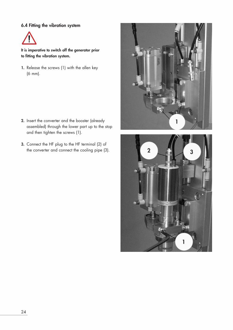
6.4 Fitting the vibration system
It is imperative to switch off the generator prior to fitting the vibration system.
1. Release the screws (1) with the allen key(6 mm).
2. Insert the converter and the booster (alreadyassembled) through the lower part up to the stopand then tighten the screws (1).
3. Connect the HF plug to the HF terminal (2) ofthe converter and connect the cooling pipe (3).
24
1
2 3
1

25
4. Put the sonotrode (4) in place and fix it with thespanner (5).
Tightening moment: 15 – 25 Nm
The ultrasound transmission system is nowready for operation.
5 4

6.5 Adjustments
1. Release the pressure from the cylinder andset the pressure controller to “0 bar”; lower theinsert manually down to the stop above theanvil.
2. Place the cutting edge of the sonotrode exactlyto the cutting edge of the anvil at the end of theradius.
3. Release the nut (2) and tighten the screw (1) upto the stop of the cutting table (3). Then removethe sonotrode by a few decimal units from theanvil.
4. Adjust the pressure to 2 kg and step on thepedal (16) in order to activate cutting.Then proceed to adjust the screw (1) until themachine performs a clean cut of the fabric.
5. Lock the nut (2) and the machine is now readyfor operation.
Do not touch the sonotrode.
26
1
2
3
16

27
6. Switch the unit on using the “ON/OFF”button (32).
After the US-TEST, the message>> READY <<is shown on the display (28).
7. Use the “SETUP” key to change to the * PARAMETER *>> ADJUST <<.
US-TEST
>> READY <<
* PARAMETER *>> ADJUST <<

8. After pressing the “SETUP” key, check allparameters using the “NEXT” key and enter thenominal values, if these are known from the specification.
9. Use the “SETUP” key to change to normaloperation and the unit is now ready for the firstcut of fabric.
Please refer to “Parameter adjustment”, page 34,for further information on the adjustments.
6.6 Switching off
1. Use the ON/OFF key (32) to switch off thegenerator.
28
* PARAMETER *>> ADJUST <<

29
7 Operation
7.1 Sequence of welding process7.1.1 Work cycle
Manual starter (standard mode)
1. After pressing the two buttons of the two-handedcontrol (START) simultaneously with an intervalof 0.3 seconds, the work sequence (cycle) starts.
The solenoid valve is activated and the insert islowered.
2. Continue to press the two-handed controls untilthe ultrasound is activated.
If the two-handed controls are released too early, theinsert retracts to its home position.
The ultrasonic is initiated by the trigger. Theultrasonic will stay in operation until the end of thepre-set welding time. After the expiry of the weldingtime, the sonotrode will remain over the weldedobject until the cooling time has expired. Thisprovides pressure for the setting of the weldedseam. After completion of the cycle the insert returns to itshome position. The machine is ready for the nextcycle.
Options: US-STOPFOLLOW IMPULSERESET
To clear an error press the CLR button.

Impulse (reduced safety)1. When the two buttons of the two-handed control
(START) are pressed simultaneously in an intervalof 0.3 seconds, the work sequence (cycle) starts.
This activates the solenoid valve and the insert islowered.
From this point onwards the buttons of the two-handedcontrol must not be kept depressed.
The ultrasonic is initiated by the trigger. The ultraso-nic will stay in operation until the end of the pre-setwelding time. After the expiry of the welding time,the sonotrode will remain over the welded objectuntil the cooling time has expired. This providespressure for the setting of the welded seam. After completion of the cycle the insert returns to itshome position. The machine is ready for the nextcycle.
Options: US-STOP FOLLOW IMPULSE RESET
To clear an error press the CLR button.
Automatic (for automatic operation without safety)The work sequence is started by an impulse lasting100 ms at the input of START 1 (STO2). The solenoid valve is activated and the insert is lowered.The ultrasonic is now activated and will be in operation while the pedal is being depressed. Aftercompletion of the work cycle, the insert will retractto its home position. The machine is ready for thenext cycle.
Options: US-STOP FOLLOW IMPULSE RESET
To clear an error press the CLR key or start a newwork sequence.If there is a HARDWARE error, the error can only becleared by switching off the unit.
30

31
7.1.2 OptimisationIn order to optimise the welding process,• only one parameter must be changed at a time, • the welding result must be checked after each
change of a parameter.
Never change several parameters at the same time.
If one changes several parameters at the sametime, it is not possible to establish which of theparameters has had an effect on the welding result.
7.1.3 Parameter setupSetting parameters are available according toinitialization of generator. They can be modified asrequired.For activating the parameter setup see followingpage.
Parameters to be set upSetting [ADJUSTING :]Part counter [PART :]Welding time [WELDTIME :]Hold time [HOLDTIME :]Trigger [TRIGGER :]After-pulse [AFTERPULSE :]Amplitude [AMPLITUDE :]Performance limits [PERFORMANCE MIN:]
[PERFORMANCE MAX:]After impulse [AFTERPULS :]
It is advisable to record the respective changes in asetup log in order to be able to return to existing settings whenever necessary.

32
7.1.4 Description of setting parameters
Setting [ADJUSTING :]• Press both start buttons within 0.3 seconds to
lower the actuator. Keep the start buttonsactuated until safety switch is reached. Pressstart buttons again to move actuator backto the home position.
Part counter [PART :]• The part counter steps up by one after each
sound welding. Press CLR key to reset partcounter.
• Maximum display: 9999999
Welding time [WELDTIME :]• Duration of welding.• Setting range: 0.00 – 9.99 s• Standard setting: 1.00 s
This parameter is operative only if the function[WELDTIME: TIMER] is operative in the * SYSTEM--INIT *.
Hold time [HOLDTIME :]• Upon exipation of the welding time the horn
keeps exertingpressure on the welding object for the HOLD TIME.• Setting range: 0.00..9.99 s• Standard setting: 1.00 s
Trigger [TRIGGER :]• Upon reaching the TRIGGER, the generator is
started. The FU-trigger point is determined by aforce sensor.
• Setting range: 0.00 – 9.9 FU
This parameter is operative only if the [TRIGGER:FU] function is operative in the * SYSTEM--INIT *.

33
Trigger [TRIGGER :]• Upon reaching the TRIGGER, the welding
is released.• Setting range: 0.00 – 3.99 s
This parameter is operative only if the [TRIGGER:TIMER] function is operative in the * SYSTEM--INIT *.
After impulse [AFTER.PULSE]• Duration of after impulse after end switch
shut off:• Setting range: 0.00 – 1.99 s• Standard setting: 0.00 s
Amplitude [AMPLITUDE :]• The amplitude may be reduced from 100% to
60% by step of 5%. A change of the boostermay thus be avoided.
• Output amplitude: see page 64• Setting range: 1 – 9 (9 = 100%)• Standard setting: 5
Maximum output power drops with a reduction of theamplitude.

34
7.2 Parameter set-up procedure
An ultrasonic vibration system must be connected.Do not touch horn!
1. Press the ON/OFF key.
2. The generator starts with a two seconds' self-testwhile warming up. After the self-test the vibrationsystem is tested again for a 1/2 second.
3. Upon termination of tests the message>> READY <<PART: 1234567 appears on the display.
4. Press the SETUP key.
5. To move to the next parameter setting: pressthe NEXT key. The display shows the nextparameter. To return to the previous parametersetting press the PREV key.
6. Move to the required point on the counter withthe cursor keys LEFT (<–) or RIGHT (–>).
7. Increase the value with the UP ( ) cursor key ordecrease the value with the DOWN ( ) cursorkey.
8. To move to the next parameter setting: pressthe NEXT key. The display shows the nextparameter.
9. Exit the parameter set-up with the SETUP key.The system is ready for welding.
–>
–>
>> READY <<PART : 1234567
* PARAMETER *>> ADJUSTING <<
* PARAMETER *PART : 1234567
* PARAMETER *WELDTIME: 9.99s
* PARAMETER *HOLDTIME : 9.99s
* PARAMETER *TRIGGER : 9.99s
* PARAMETER *AFTERIMPLUSE: 9.99s
* PARAMETER *AMPLITUDE : 9
>> US-TEST <<++++++++++++
RINCO ULTRASONICSWITZERLAND

35
7.3 Automatic connection
The operating switch (ON / OFF) can be activatedor deactivated. To open the generator module (32)it is necessary to,
1. release the four screws (34), 2. pull the handles (26) outwards towards the
guides. The steady is in the rear top position (35).
Standard positionThe steady is in the top position and the ON / OFFswitch (32) is activated.
Automatic optionThe steady is in the bottom position and theON / OFF switch (32) is deactivated. Start-up willbe initiated automatically when the unit isconnected to mains power.
Steady is in thetop position
Steady is in thebottom position

8 Elements
8.1 ConverterThe converter is a sensitive instrument. Please hand-le it with great care! The converter (24) is the coreof every ultra sonic welding instrument. It belongsto the group of piezoelectric converters.Piezoelectric converters are composed of severalceramics disks that change their shapes undervoltage.With an ultra sonic welding converter, an AC volta-ge with a nominal frequency of (e.g. 20 kHz) isused. This electric signal is turned into mechanicaloscillations of the same frequency by the piezo-electric elements. At the front end, "K1" of theconverter (24) a mechanical oscillation in axialdirection is created. The oscillating amplitude isnormally too minute to be useful and is thereforeamplified with a booster (25).The efficiency of a Piezo converter is extremelyhigh. The minute energy losses during conversionare traceable in the heat build up in of the converter. The special build of converters enableremaining heat to dissipate by natural convection.Optimally, for special applications the heatbuild up must be dissipated with additionalventilators.
The converter should not be warmer than 50° (40°with 70 kHz) centigrades at the contact point "K1".Converters, boosters, horns and generators maysustain damage if overheated.The converter must be tightened with torque valueslisted in the following table.
Frequency Torque
20 kHz 30-40 Nm35 kHz 15-25 Nm70 kHz 1.8-2.2 Nm
36

37
8.2 BoosterApplying the correct amplitude to the horn is one ofthe most important factors in ultra sonic welding.The geometric shape of the horn must be adaptedto the object to be welded. Setting the correctamplitude is often difficult. The booster amplifies theamplitude of the converter at a preset ratio.In our example 1:2.The amplification resp. dampening factor isspecified as a ratio. The ratio is color coded andhas a numerical designation (A). (see table)
Frequency Torque
35 kHz 15-25 Nm
The ultrasonic welding instruments can be deliveredwith the following types of boosters:
Reduce Colour Material Booster Colour MaterialBooster1:0.5 blau Aluminium 1:1 grün Aluminium1:0.6 violett Aluminium 1:1.5 gelb Aluminium
1:2 weiss Titanandere Verhältnisse 1:2.5 schwarz Titanauf Anfrage 1:3 braun Titan
ExampleConverter: 5 µmBooster: 1:2 –>10 µmSonotrode: 1:3 –>30 µm
Converter = 5 µm
Booster =1:2 –>10 µm
Sonotrode =1:3 –> 30 µm
A

8.3 Horn
Any kind of change to the metallic body of thehorn influences the oscillating characteristics and there-fore none should be made without consulting themanufacturer!
The horn transmits the ultra sonic energy to theobject to be welded in form of intense oscillationscreated by the converter.Work pieces come in various shapes and the hornsmust be adapted to the shapes as required. Thehorn is an acoustic body tuned to the frequency ofresonance.That sets limits to the shapes it may take. Thegeometric shape of the horn should be kept assimple as possible.In addition to the geometric shapes, other importantfactors are to be considered:
1. The horn has to be tuned to the frequencies ofresonance according to the table. frequency of resonance Tolerace35 kHz ±50 Hz +150 / -250 Hz
2. To let the horn oscillate correctly, it should beshaped to move in the most axial direction tothe surface to be welded, with the aim oftransmitting the most pulses from the frontal areaof the horn onto the object to be welded.
3. The amplitude of the horn is determined by theshape of the horn.
Most important in manufacturing the horn is:
• Extensive knowledge about the load factors ofthe various materials.
38

39
8.3.1 Horn materialsHorns must be made of special high load material.Only high load aluminum, titan and steel alloy areused.The choice of material depends mostly on theintended application.Other factors also influence the choice of material:
1. Rigidity of the material used for the horn inconnection with the targeted oscillationamplitude.
2. Surface properties of the work piece and therelated surface treatment properties.
3. The sound transmission properties.4. The heat transmission properties of the horn
material.
It must be taken into consideration that the horn issubjected too extreme mechanical loads.It is therefore of utmost importance to shape thehorn in such a way that the plastics part to bewelded is welded under optimal conditions.With abrasive plastics, a coating of the horn surfa-ce will increases its life span.RINCO has years of experience in manufacturinghorns. Manufacturing horns without the theoreticaland practical experience leads to unsatisfactoryand bad welding results and to poor productquality.
In some cases the oscillating system and the generatormay be damaged.
The horn must be fastened with a tightening torque to15 – 25 Nm.

8.4 Cutting table for work piece (anvil)The cutting table for the work piece or anvil hasseveral functions:
• to maintain the distance between the cuttingedge of the work piece and the cutter,
• counter plate for the cutter so that this willcarry out a clean cut,
• absorbing any vibrations and avoidingexcessive wear.
In many cases, the quality of the cut depends onthe shape of the cutting table and the work piece. It is recommended that the manufacturer of thesonotrode also produces the cutting table since hewill be more familiar with the requirements ofthe application.
40

41
9 Replacement
9.1 Replacing the booster
Before releasing the converter clamp (2) it is imperativethat the main power switch is turned “OFF”.
1. Release the bolts and the sonotrode (3) usingthe spanner.
2. Release the screw fixing (1) with the allen key(5mm).
3. Pull out the cooling pipe (4).
4. Remove the plug from the HF terminal (5) ofthe converter.
5. Move the whole vibration system downwards.
21
3
4
5
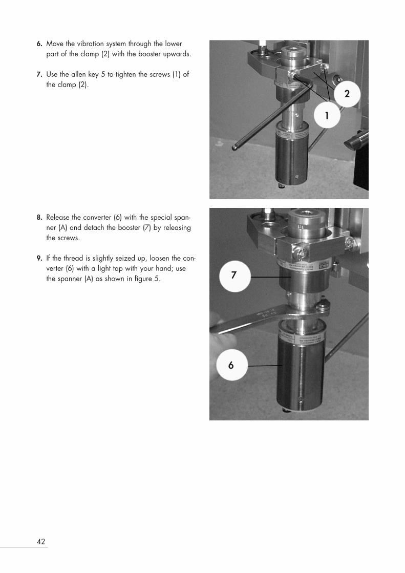
6. Move the vibration system through the lowerpart of the clamp (2) with the booster upwards.
7. Use the allen key 5 to tighten the screws (1) ofthe clamp (2).
8. Release the converter (6) with the special span-ner (A) and detach the booster (7) by releasingthe screws.
9. If the thread is slightly seized up, loosen the con-verter (6) with a light tap with your hand; usethe spanner (A) as shown in figure 5.
42
1
2
7
6

43
10. Again release the clamp (2).
11. Pull the booster (7) out.
12. Attach a new booster to the bracket (2) withthe thread facing downwards so that it can bescrewed to the converter (6).
A
7
2
6

13. Lock the clamp (2) by tightening the screws (1).
14. Make the screw connection between the con-verter (6) and the booster (7) and use the spe-cial spanner (A) to pull tight.
15. Again release the clamp (2).
16. Pull the converter (6) together with the booster(7) (which has been screwed to the converter)out and turn it.
44
7
6
7
6
2
A
2
1

45
17. Again place the complete vibrationsystem with the converter (6) uppermost.
18. Connect the plug to the HF terminal (5) andconnect the cooling pipe (4).
19. Turn the screws (1) to tighten the clamp (2) ofthe converter.
20. Again make the screw connection betweenthe sonotrode (3) and the booster (7).
21. Tighten the sonotrode (3) with the spanner (8).
7
5
1
8
4
1
2
3

22. Align the sonotrode vertically at the anvil byreleasing the clamp (2) with the screws (1)and then tightening the clamp (2) again onceit has been positioned.
23. Release the fixing clamp of the anvil (9) withthe screws (10). Slide the bar of the anvilalong until the cutting edge of the sonotrode isplaced exactly at the end of the radius; thenretighten the clamp (9).
24. For further information regarding theadjustment of the cutting edge see section6.5 Adjustments.
46
1
9
10
2

47
9.2 Parameter initializationTo prepare the Multipress and the Generator fortheir various tasks, the individual press functionsare initialized according to the mode of operationvia the generator control system.
Press the PREV key and keep this depressed duringfiring up in order to activate the standard start-up. Press the CLR key in order to confirm the standardstart-up.When pressing the SETUP key the standard start-upwill be interrupted.
In the * SYSTEM--INIT * menu you can select thefollowing functions:• START [MANUAL/IMPULSE/
AUTOMATIC]• TRIGGER [FU/TIMER/EXTERNAL/RS/OFF]• WELDING [TIMER/EXTERNAL]• VALVE [ON/OFF]• END SWITCH [ON/OFF]• SOFTSTART [1-9]• AFTERPULSE [ON/OFF]• LANGUAGE [GERMAN/
ENGLISH/FRENCH/ITALIAN/SPANISH/DUTCH/DANISH/NORWEGIAN/SWEDISH/FINNISH]
• AMPLITUDE* INTERNAL/EXTERNAL]• SDF* [ON/OFF]• TRIGGER [BEFORE/AFTER]• PERFORMANCE• LIMIT* [ON/OFF]

9.2.1 Description of selectable functions
START (MANUAL)• The generator must be started up MANUALLY.
TRIGGER (FU/TIME)• The TRIGGER can be confirmed with FU or
TIME.• Standard setting: FU
WELDING TIME (TIME)• The generator must be started up in TIME.
VALVE (YES/NO)• The generator must be started up in the YES
position.
F-C US (YES/NO)• This function is activated when a unit was star-
ted with YES.• Standard setting for initiation: NO• A signal at input 2 or 3 of the connection
interface interrupts the ultrasound. After theinterruption a second welding can be carriedout by pressing the two-handed controls. If nosignal is emitted, the ultrasound will beinterrupted once the welding time has elapsed.An error message is activated.
LANGUAGE (SPANISH/ENGLISH)• Standard setting: ENGLISH
AMPLITUDE (YES/NO)• If NO has been selected for starting up, the
amplitude can be selected in the parametersubmenu.
• Standard setting: NO• When YES has been selected for start-up, the
amplitude can be selected outside with thepotentiometer or with a voltage of 0 – 5 V DC.
Option A• With the 10 Ω potentiometer
Option B• With a voltage of 0 – 5 V.• If the internal voltage is not used, the earth
connection GND 5 V is connected outside toGND.
• 0 V = 60%, 5 V = 100%
48

49
SOFTSTART (1-9)• The duration from starting up to reaching the full
amplitude can be adjusted in 9 steps.
1 Slow start of vibration for sonotrodes with alarge volume
9 Fast start of vibration for small sonotrodes
• Standard setting: 7 (See illustration)
SDF (YES/NO)• This function is not activated unless YES is selec-
ted for start-up. • Standard setting: NO• Starting aid for starting up sonotrodes with
large volume.
TRIGGER (BEFORE/AFTER)• In the case of AFTER, the trigger is activated
after the safety contact. • In the case of BEFORE, the trigger is activated
during the lowering movement. It is requiredwhen the welding distance is more than 6 mm.
• Standard setting: AFTER
RESET• A signal of 24 V DC at the RESET input will
interrupt the work cycle.The machine will retract to its home position andindicate an error.

9.2.2 System initialization process
A oscillating system must be connected.Do not touch the horn.
1. Press ON/OFF button.
2. The generator performs a self-test for twoseconds during start up.
3. Keep the SETUP key pressed during start up.The display shows:* SYSTEM--INIT *CODE : 000
4. Using the cursor keys, set code to 472.Acknowledge by pressing the SETUP key.
5. Within the menus individual settings can beselected with the CLR key. Numerical input aremade with the cursor keys.
6. Jump to next function. Press NEXT key. The nextselectable function is displayed. To return to theprevious selectable function press PREV key.
7. Quit SYSTEM - INIT with the SETUP key.After the self-test the oscillating system is testedfor half a second.
50
RINCO ULTRASONICSWITZERLAND V2E0
* SYSTEM--INIT *CODE : 000
* SYSTEM--INIT *CODE : 472
* SYSTEM--INIT *START : MANUAL
* SYSTEM--INIT *TRIGGER : FU
* SYSTEM--INIT *WELDTIME : EXT.
>> US-TEST <<++++++++++++
>> READY <<PART : 1234567
* SYSTEM--INIT *VALVE : ON
* SYSTEM--INIT *US-STOP : OFF

51
* SYSTEM--INIT *SOFTSTART : 5
* SYSTEM--INIT *LANGUAGE:ENGLISH
* SYSTEM-INIT *AMPLITUDE: OFF
* SYSTEM--INIT *SDF : OFF
* SYSTEM-INIT *TRIGGER : AFTER

10 Cleaning and Servicing
10.1 General servicing tasks
All cleaning and servicing must be carried out by qua-lified personnel.
Prior to starting servicing, it is imperative to check thatall services, such as power and compressed air, havebeen switched off.
Important: never clean the keyboard and the front ofthe generator with corrosive agents.
Neither the cutting station nor the generator requirespecial servicing. However, regular cleaning of the following partsenhances the service life of the unit: • pneumatics group (5),• vibration system (6),• anvil (7),• carriage (10)
10.2 Vibration system and carriage Daily cleaning:• Converter (6)• Booster (7)• Sonotrode (3)
52
5
4
10
6
7 8 9
3
2
1
6
7
3

53
10.3 Pneumatics group
No servicing required.
10.4 Generator
Ensure that the display screen of the generator isalways clean.

10.5 Oscillating system
Work may only be carried out on the vibration systemand converter housing when the mains voltage is switched off! High voltage!
Avoid contact with the RF connection of theconverter.
Never connect any measuring instruments to theRF socket of the converter!
The converter is electrically charged even afterswitching off the generator.
10.6 Threaded couplingConverter (24), booster (25) and horn (9) arescrewed together.
Torque: 35 kHz 15-25 Nm
Black spots on the surfaces of the booster (25) orthe horn (9) are easily removed.
1. Place a polishing cloth on an even surface2. Draw blackened spot over the cloth.
54

55
11 Error messages and trouble shooting
Troubleshooting may only be carried out byspecially trained staff. In case of doubt, contactthe service centre or the manufacturer directly(see appendix).
11.1 Error messages / corrective action:switching on
Error Possible cause Error elimination
Generator cannot be – no voltage supply – insert mains plugswitched on – EMERGENCY STOP button pressed – release EMERGENCY STOP button
– fuse faulty – test fuses F1– F5– module not in its housing – insert module and bolt together
After being switched on, – vibration system not in use – use vibration systemthe display shows: – RF cable not plugged in the – plug in RF cable
vibration system or generator– error in vibration system:
a) not screwed together firmly enough – screw together more firmlyb) horn defective our outside – replace hornthe frequencyc) booster defective – replace boosterd) Converter defective – replace converter
11.2 Error messages and error eliminationduring adjustments and welding
Error Possible cause Error elimination
The insert is lowering but the – The setting of the trigger is very high – Select a lower settingultrasonic does not work – The pressure sensor is defective – Replace the pressure sensorIn spite of increasing the – The stop setting is very low – Adjust the stop to a higher settingwelding time, the parts donot fuseThe machine retracts to its – The safety switch was not reached – Keep the two-handed controlshome position without welding depressed until the unit reaches
the safety switch or starts welding

11.3 Generator error messagesduring operation
Error Possible causes
«OVERLOAD1» – Trigger set too highThe generator was charged over – maximum welding pressure too high100% of nominal power – Generator output too low for intended application
– Vibration system defective«OVERLOAD2» – Amplitude too low at contact cut off during cutting operationsThe generator had to utilise to the – Mains voltage below nominal tolerancefull the final stage reserve capacity«TRIGGER» – Trigger set too highTrigger point not reached after – wrong Parameter initialization10 seconds – Trigger system defective«FREQUENCY» – faulty horn or horn incorrectly tunedVibration system out of frequency – faulty boosterrange of generator – faulty converter
– faulty RF cable or RF cable not connected– faulty generator– frequency change due to coupling with the fixture
«TIME OVERFLOW» – the US-TEST key was pressed longer than 5 secondsOperation time has exceeded – the control time has been exceeded during an application using
contact cut off.«RESET» – 24V signal was aborted at entrance 7 of the InterfacesThe plant returns to stop as aresult of an external signal«ABORT» – start button releases before safety switch was reached or beforeWelding could not be carried-out hold time run outaccording to program
«HARDWARE» – defective valve in the feeder– defective pressure monitoring switch in the feeder– defective safety witch– defective upper end position switch– upper end position switch not adjusted– Stroke less than 6 mm– Malfunction in the generator– defective two-hand trigger
Cancel error by pressing the CLR key.
The «Hardware» error can only becanceled by switching the unit off.
56

57
12 Electric wiring diagrams
12.1 Wiring diagram for the SL generator 12.1.1 Operating element STO1
Input for safety switch
Input for trigger
Output from solenoid valve
Input top limit position
Input emergency stop
Input N/O 1
Input N/C 2

12.1.2 Manual starter STO2 (standard)
12.1.3 Manual starter STO2 (optional)
58
Input emergency stop
Input N/O 1
Input N/O 2
Input emergency stop
Input N/O 1
Input N/O 2

59
12.1.4 Automatic start-up STO2 (pedal)
Input emergency stop
Input N/O 1
Input N/O 2

12.1.5 Interface STO3
60
Input US-stop 1
Input US-stop 2
Output reserve
NC
Input reset
Input amplitude
Error- max. 24V / 0.5A- open in case of an error
Insert in position- max. 24V / 0.5A- open if not positioned

61
12.2 Melting strips
The melting strips are situated on the following com-ponents:
On the base of the mains terminal
Bus print
Module of generator
All fuses are of equal size: 5 x 20 mm

12.3 Listing of fuses
Generator Base of mains terminal Bus print Module of generatorF1 F2 F3 F4 F5
GM35-400 4 A/T 4 A/T 400 mA/T 4 A/T 100 mA/T GM35-600 4 A/T 4 A/T 400 mA/T 4 A/T 100 mA/T GM35-900 6,3 A/T 6,3 A/T 400 mA/T 6,3 A/T 100 mA/T
12.4 Back part of generator SL 35
1 STO12 STO23 STO34 STO45 STO5
12.5 Listing of the connection terminalsof the unit
List of generator base plates RINCO order number
STO1 Base plate 14-pole AMP 5445STO2 Base plate 7-pole AMP 5442STO3 Base plate SUB-D 15-pole 5469STO4 Base plate Lemo 1 7255STO5 Base plate 250V / 8A 120-1517
List of terminal connections RINCO order number
ST1 Plug 14-pole AMP 5443ST2 Plug 7-pole AMP 5440ST3 Plug SUB-D 15-pole 5446ST4 Plug Lemo 1 2647ST5 Mains cable 250V depending on country
62

63
13 Technical drawings and dimensions
13.1 Drawing of cutting station

13.2 Amplitude values of the GM generatormodule seriesThe different generator outputs generate differentamplitudes. The value of the amplitude describedin the diagram below refers to the respectiveconfiguration of the generator/booster/sonotrode.
The effective amplitude of the welding is directlylisted.
9 Sonotrode24 Converter25 BoosterA AmplitudeK1 Connecting surfaceK2 Connecting surface
13.3 Amplitude of SL generators with 35 kHz
64
Sonotrode Booster

65
13.4 Length of screws of the different components of the vibration system for 35 kHz
2.4 Converter
The screw is an integral part of the converter, it cannotbe removed.
25 BoosterThe connecting surfaces are placed exactly parallelbetween the front and connection face.
9 Sonotrode
9.1 Sonotrode screwThe sonotrode screw is manufactured from highlyresistant steel or titanium.
9.1

14 Addresses of technical customerservice
The RINCO ULTRASONICS customer service isavailable for you in case of faults or weldingproblems.
In order to be able to give you correct advice, ourcustomer service requires the following data:
1. Model and serial number of your unit2. An exact description of the fault or cutting
problem
Our address:RINCO ULTRASONICS AGIndustriestrasse 4CH-8590 RomanshornSwitzerland
SwitzerlandPhone 071 466 41 00Fax 071 466 41 01
InternationalPhone ++41 71 466 41 00Fax ++41 71 466 41 01www.rincoultrasonics.com
66
A

A CREST GROUP COMPANY
R RINCO ULTRASONICS AGIndustriestrasse 4CH-8590 Romanshorn1Switzerland
Phone +41 71 466 41 00Fax +41 71 466 41 [email protected]