
Operating Instructions Turbimax CUS71D - Endress+Hauser€¦ · Operating Instructions Turbimax...
40
Products Solutions Services BA00490C/07/EN/03.13 71209086 Operating Instructions Turbimax CUS71D Ultrasonic interface sensor Immersion sensor for interface measurement
Transcript of Operating Instructions Turbimax CUS71D - Endress+Hauser€¦ · Operating Instructions Turbimax...

Products Solutions ServicesBA00490C/07/EN/03.1371209086
Operating InstructionsTurbimax CUS71DUltrasonic interface sensorImmersion sensor for interface measurement

Endress+Hauser
About this document
Notes on safety iconsThe structure, signal words and safety colors of the signs comply with the specifications of ANSI Z535.6 ("Product safety information in product manuals, instructions and other collateral materials").
Symbols
Safety message structure Meaning
DANGER!
Cause (/consequences)Consequences if safety message is not heeded‣ Corrective action
This symbol alerts you to a dangerous situation.Failure to avoid the situation will result in a fatal or serious injury.
WARNING!
Cause (/consequences)Consequences if safety message is not heeded‣ Corrective action
This symbol alerts you to a dangerous situation.Failure to avoid the situation can result in a fatal or serious injury.
CAUTION!
Cause (/consequences)Consequences if safety message is not heeded‣ Corrective action
This symbol alerts you to a dangerous situation.Failure to avoid this situation can result in minor or medium injury.
NOTICECause/situationConsequences if safety message is not heeded‣ Action/note
This symbol alerts you to situations that can result in damage to property and equipment.
Additional information, tips
Permitted or recommended
Forbidden or not recommended

Turbimax CUS71D
Endress+Hauser 3
Table of contents
1 Basic safety instructions . . . . . . . . . . . . . 41.1 Requirements for the personnel . . . . . . . . . . . . . . . 41.2 Designated use . . . . . . . . . . . . . . . . . . . . . . . . . . . . . 41.3 Workplace safety . . . . . . . . . . . . . . . . . . . . . . . . . . . 41.4 Operational safety . . . . . . . . . . . . . . . . . . . . . . . . . . . 41.5 Product safety . . . . . . . . . . . . . . . . . . . . . . . . . . . . . . 5
2 Incoming acceptance and product identification . . . . . . . . . . . . . . . . . . . . . . 6
2.1 Incoming acceptance . . . . . . . . . . . . . . . . . . . . . . . . 62.2 Nameplate . . . . . . . . . . . . . . . . . . . . . . . . . . . . . . . . . 62.3 Scope of delivery . . . . . . . . . . . . . . . . . . . . . . . . . . . . 62.4 Certificates and approvals . . . . . . . . . . . . . . . . . . . . 6
3 Installation . . . . . . . . . . . . . . . . . . . . . . . . 73.1 Dimensions . . . . . . . . . . . . . . . . . . . . . . . . . . . . . . . . 73.2 Installation instructions . . . . . . . . . . . . . . . . . . . . . . 83.3 Installation conditions . . . . . . . . . . . . . . . . . . . . . 103.4 Post-installation check . . . . . . . . . . . . . . . . . . . . . 11
4 Electrical connection . . . . . . . . . . . . . . . 124.1 Connecting to the transmitter . . . . . . . . . . . . . . . 124.2 Post-connection check . . . . . . . . . . . . . . . . . . . . . 13
5 Device description . . . . . . . . . . . . . . . . . 145.1 Sensor design . . . . . . . . . . . . . . . . . . . . . . . . . . . . . 145.2 Measuring principle . . . . . . . . . . . . . . . . . . . . . . . 145.3 Function . . . . . . . . . . . . . . . . . . . . . . . . . . . . . . . . . 145.4 Sensor monitoring . . . . . . . . . . . . . . . . . . . . . . . . 145.5 Parametrization in the process . . . . . . . . . . . . . . 155.6 Factory settings . . . . . . . . . . . . . . . . . . . . . . . . . . . 155.7 Cyclic cleaning . . . . . . . . . . . . . . . . . . . . . . . . . . . . 15
6 Commissioning. . . . . . . . . . . . . . . . . . . . 166.1 Firmware update . . . . . . . . . . . . . . . . . . . . . . . . . . 166.2 Basic settings . . . . . . . . . . . . . . . . . . . . . . . . . . . . . 16
7 Diagnostics and troubleshooting. . . . . 29
8 Maintenance. . . . . . . . . . . . . . . . . . . . . . 308.1 Cleaning the sensor . . . . . . . . . . . . . . . . . . . . . . . 30
9 Repair. . . . . . . . . . . . . . . . . . . . . . . . . . . . 319.1 Spare parts . . . . . . . . . . . . . . . . . . . . . . . . . . . . . . . 319.2 Return . . . . . . . . . . . . . . . . . . . . . . . . . . . . . . . . . . . 319.3 Disposal . . . . . . . . . . . . . . . . . . . . . . . . . . . . . . . . . 31
10 Accessories. . . . . . . . . . . . . . . . . . . . . . . 3210.1 Assemblies . . . . . . . . . . . . . . . . . . . . . . . . . . . . . . . . 3210.2 Holder . . . . . . . . . . . . . . . . . . . . . . . . . . . . . . . . . . . . 3210.3 Transmitter . . . . . . . . . . . . . . . . . . . . . . . . . . . . . . . 3310.4 Cable extension . . . . . . . . . . . . . . . . . . . . . . . . . . . . 33
11 Technical Data . . . . . . . . . . . . . . . . . . . . 3411.1 Input . . . . . . . . . . . . . . . . . . . . . . . . . . . . . . . . . . . . . 3411.2 Performance characteristics . . . . . . . . . . . . . . . . . 3411.3 Environment . . . . . . . . . . . . . . . . . . . . . . . . . . . . . . 3411.4 Process . . . . . . . . . . . . . . . . . . . . . . . . . . . . . . . . . . . 3411.5 Mechanical construction . . . . . . . . . . . . . . . . . . . . 34
Index . . . . . . . . . . . . . . . . . . . . . . . . . . . . 36

Basic safety instructions Turbimax CUS71D
4 Endress+Hauser
1 Basic safety instructions
1.1 Requirements for the personnel‣ Installation, commissioning, operation and maintenance of the measuring system must
only be carried out by trained technical personnel.‣ The technical personnel must be authorized by the plant operator to carry out the
specified activities.‣ The electrical connection may only be performed by an electrical technician.‣ The technical personnel must have read and understood these Operating Instructions
and must follow the instructions they contain.‣ Measuring point faults may only be rectified by authorized and specially trained
personnel.
Repairs not described in the enclosed Operating Instructions may only be carried out directly at the manufacturer's or by the service organization.
1.2 Designated useCUS71D is an immersion sensor designed for interface measurement in water and wastewater.
The sensor is particularly suited for use in the following applications:• Wastewater treatment: primary clarifier, sludge thickener, secondary clarifier• Water purification: settling basin after flocculant dosage, sludge height in contact sludge
process• Static separation process: With / without slow stirring and without air inclusion.
Any other use than the one described here compromises the safety of persons and the entire measuring system and is not permitted.The manufacturer is not liable for damage caused by improper or non-designated use.
NOTICEUse outside specificationIncorrect measurements, malfunctions and even measuring point failure are possible‣ Only operate the product in line with the product specifications.‣ Pay particular attention to the technical data of the sensor.
1.3 Workplace safetyAs the user, you are responsible for complying with the following safety conditions:• Regulations for explosion protection• Installation instructions• Local standards and regulations
1.4 Operational safety‣ Before commissioning the entire measuring point, make sure all the connections are
correct. Ensure that electrical cables and hose connections are not damaged.‣ Do not operate damaged products, and safeguard them to ensure that they are not
operated inadvertently. Mark the damaged product as defective.‣ If faults cannot be rectified, the products must be taken out of service and secured against
unintentional commissioning.

Turbimax CUS71D Basic safety instructions
Endress+Hauser 5
1.5 Product safetyThe product is designed to meet state-of-the-art safety requirements, has been tested and left the factory in a condition in which it is safe to operate. Relevant regulations and European standards have been observed.

Incoming acceptance and product identification Turbimax CUS71D
6 Endress+Hauser
2 Incoming acceptance and product identification
2.1 Incoming acceptance‣ Make sure the packaging is undamaged!‣ Inform the supplier about any damage to the packaging.
Keep the damaged packaging until the matter has been settled.‣ Make sure the contents are undamaged!‣ Inform the supplier about damage to the contents. Keep the damaged products until the
matter has been settled.‣ Check that the order is complete and agrees with your shipping documents.‣ The packaging material used to store or to transport the product must provide shock
protection and humidity protection. The original packaging offers the best protection. Also, keep to the approved ambient conditions (see "Technical data").
‣ If you have any questions, please contact your supplier or your local sales center.
2.2 NameplateCompare the order code indicated on the nameplate to the product structure and your order.
The nameplate contains the following information:• Manufacturer data• Order code (device version)• Extended order code• Serial number
To discover what sensor version you have, enter the order code on the nameplate into the search screen at the following address:www.products.endress.com/order-ident
2.3 Scope of deliveryThe scope of delivery comprises:• 1 sensor Turbimax CUS71D in the ordered version• 1 Operating Instructions BA00490C/07/EN
If you have any questions, please contact your supplier or your local sales center.
2.4 Certificates and approvalsDeclaration of conformityThe product meets the requirements of the harmonized European standards. It thus complies with the legal requirements of the EC directives.The manufacturer confirms successful testing of the product by affixing the 4 symbol.

Turbimax CUS71D Installation
Endress+Hauser 7
3 Installation
3.1 Dimensions
a0014922
Fig. 1: Dimensions of standard sensor
a0014921
Fig. 2: Dimensions of sensor with wiper
mm (inch)
20 (
0.7
9)
12 (
0.4
7)
NPT 3/4"
G1
74.3 (2.93)
43.3
(1.7
0)
68.8
(2.7
1)
34.7 (1.37)
46 (
1.8
1)
mm (inch)
20
(0
.79
)1
2 (
0.4
7)
NPT 3/4"
G1
74.3 (2.93)
11
0 (
4.3
3)
13
5.5
(5
.33
)
34.7 (1.37)
46
(1
.81
)
19
(0
.75
)

Installation Turbimax CUS71D
8 Endress+Hauser
3.2 Installation instructions
3.2.1 Measuring systemA complete measuring system comprises:• Ultrasonic sensor Turbimax CUS71D• Multi-channel transmitter Liquiline CM44x
and optional:• Weather protection roof CYY101• Holder system Flexdip CYH112• Fixed or rotatable immersion pipe Flexdip CYA112
a0014923
Fig. 3: Ultrasonic sensor with holder system and multi-channel transmitter
1 Holder system Flexdip CYH112 5 Ultrasonic sensor Turbimax CUS71D2 Multi-channel transmitter Liquiline CM44x 6 Perpendicularly from all sides3 Weather protection roof 7 Splash protection cap4 Assembly Flexdip CYA112

Turbimax CUS71D Installation
Endress+Hauser 9
3.2.2 Measuring system with pendulum holder
a0015156
Fig. 4: Measuring system with pendulum adapter
The PVC sensor protector protects the ultrasonic sensor from getting damaged by the surface skimmer.
When using surface skimmer do not use sensors with wiper.
1 Cross clamp of holder system Flexdip CYH112 3 Assembly Flexdip CYA112 with CUS71D2 Pendulum adapter of holder system Flexdip
CYH112 4 PVC sensor protector

Installation Turbimax CUS71D
10 Endress+Hauser
3.3 Installation conditionsBasin configuration
a0002181
Fig. 5: Basin configuration
A SensorB Minimum distance of sensor to basin wall = 45 cm (1.48 ft.)C Reference point e.g. water surfaceD Zero pointE Basin depthF Opening angle of ultrasonic cone, 6°
Installation instructionsLook at the construction drawing of the basin for a suitable position for the sensor. In doing so, you must take the following factors into account:
• The minimum distance between the basin wall and the sensor is 45 cm (1.48 ft.) (sensor emits ultrasound in conical form).
• There should not be any basin wall protrusions or piping in the measuring range below the sensor. Scrapers that are only temporarily in this area are permitted.
• Do not install the sensor in zones in which air bubbles, turbulence, high levels of turbid material or suspended matter or foam formation occur (e.g. inlet).
• Using an immersion tube, install the sensor 20 cm ( 0.66 ft.) beneath the surface of the water.
• The transmitter may not be installed in a second enclosure (heat accumulation).• If possible, do not install the transmitter near high voltage sources. In addition, also avoid
sources of magnetic fields, e.g. large transformers or frequency converters.• The system can only detect a separation zone if there is a clear transition between the
zones. Unclear transition from the liquid to the solid phase cannot be detected.
A B
C
D
E
6°
F

Turbimax CUS71D Installation
Endress+Hauser 11
Circular Clarifier
a0015232
Fig. 6: Basin configuration in circular clarifier
3.4 Post-installation check‣ Sensor and cable undamaged?‣ Cap undamaged?‣ Compliance with permissible sensor installation position?‣ Is the sensor installed in an assembly and is not suspended from the cable?‣ Avoid moisture by rain by putting the protective cap on the assembly?
1/3 2/3
1
2
3
4
5
1/3 2/311
1213
14
A
B
A View from top B Cross section1 Surface skimmer 11 Sensor2 Walk way 12 Hand rail3 Sensor mounting 13 Surface skimmer4 Bottom rake 14 Bottom rake5 Rake direction

Electrical connection Turbimax CUS71D
12 Endress+Hauser
4 Electrical connectionWARNING!
Device is energizedImproper connection can cause injury or death.‣ The electrical connection must only be carried out by a certified electrician.‣ Technical personnel must have read and understood the instructions in this manual and
must adhere to them.‣ Prior to beginning any wiring work, make sure voltage is not applied to any of the cables.
4.1 Connecting to the transmitterYou can connect only one sensor to the transmitter Liquiline CM442.You can connect up to four sensors to the transmitters Liquiline CM444 and CM448.
The sensor is connected to the transmitter as follows:
a0012460
Fig. 7: Sensor connection
The maximum cable length is 100 m (328 ft).
To extend the sensor cable, the following accessories are recommended:• Measuring cable CYK11 with ferrules and• Junction box "cable / cable"

Turbimax CUS71D Electrical connection
Endress+Hauser 13
4.2 Post-connection check
Instrument status and specifications Remarks
Are the sensor, assembly, junction box or cable damaged? Visual inspection
Electrical connection Remarks
Does the supply voltage of the transmitter match the specifications on the nameplate?
Are the installed cables strain-relieved and not twisted ?
Is the cable type route completely isolated ? Power cable/weak current cable
Are the power supply and signal cable correctly connected to the transmitter ?
Use the connection diagram of the transmitter.
Long enough length of cable core stripped and correct in terminal? Check seating (pull slightly)
Are all the screws terminals properly tightened ? Tighten
Are all the cable entries installed, tightened and sealed ? For cable entries lateral: cable loops downwards for water to be able to drip off.Are all the cable entries installed downwards or lateral ?

Device description Turbimax CUS71D
14 Endress+Hauser
5 Device description
5.1 Sensor designThe sensor is designed for continuous in-situ determination of interfaces.
The sensor includes all necessary modules:• Power supply• Ultrasonic source sends the measurement signals.• Ultrasonic receiver receives the measurement signals, digitalizes and converts the signals
to a measurement value.• The microcontroller of the sensor controls the internal operations and the data
transmission.
All data - including calibration data - are stored in the sensor. That means:• A pre-calibrated sensor can be used at the measuring point.• The sensor can be calibrated externally.• The sensor can be used at multiple measuring points with different calibration data.
5.2 Measuring principleA piezoelectric crystal is integrated in a flat cylindrical plastic housing. When the crystal is excited by an electrical voltage, it generates a sonar signal. The ultrasonic waves are transmitted at a frequency of 657 kHz at an angle of 6° to scan the separation zones.The parameter measured is the time it takes for the transmitted ultrasonic signal to reach the solid particles in the separation zone and return to the receiver.A sensor version with wiper avoids film formation at the sensor membrane.
5.3 FunctionThe speed of the sound varies according to the physical properties of the measuring medium and is affected by temperature and air pressure. The liquid zones and solids content of the medium also vary.To obtain precise measurement results, it is therefore vital to adapt system variables to the process, e. g. pulselength and the speed of the sound.
The CM44x offers the following possibilities for signal evaluation:• Mask out regions where the separation zone is not expected.• Evaluate received signal strengths differently.• Select leading or trailing signal edges in the evaluation.• Amplify sensor signals at different rates, e. g. for floating sludge.• Define a region (gate) above and below the separation zone. Signal evaluation only takes
place in the defined region. The gate wanders with the separation zone. This makes smoothing algorithms unnecessary.
5.4 Sensor monitoringThe optical signals are continuously monitored und checked for plausibility.Discrepancies are reported via error messages by the transmitter.
The sensor check system of the Liquiline CM44x reports the following failure conditions:• Implausible high or low measuring values• Disturbed controlling due to erroneous measuring values

Turbimax CUS71D Device description
Endress+Hauser 15
5.5 Parametrization in the processThe settings are performed by inputs at Liquiline CM44x (see BA00451C/07/EN).
5.6 Factory settingsThe sensor is initialized in the factory. After adjusting the tank parameters the sensor is ready for the standard applications without further adjustments. The factory settings are nonvolatile.
5.7 Cyclic cleaningFor cyclic cleaning a ultrasonic sensor with integrated wiper is available. The time interval is selectable via software.

Commissioning Turbimax CUS71D
16 Endress+Hauser
6 Commissioning
6.1 Firmware updateTurbimax CUS71D needs a firmware version "01.02.02-0048" or later. Your current firmware version can be found at: Menu/Diagnostics/System information/Software versionIf your controller is equipped with an older firmware version you have to perform a firmware update.
First save your current setup on an SD card since a firmware update overwrites your settings with the factory settings. After updating the firmware, you can restore your setup by uploading it from the SD card.
To install a firmware update, you must have the update available on an SD card.
1. Insert the SD card into the controller card reader.
2. Go to: Menu/Setup/General settings/Extended setup/Data management/Firmware update.--> The update files on the SD card are displayed.
3. Select the desired update and select yes when the following question is displayed: The current firmware will be overwritten. After this the device will reboot. Do you want to proceed?--> The firmware is loaded and the device is then started with the new firmware.
6.2 Basic settingsAfter switching on the controller you have to perform some settings to get correct measurement
After system initialization the adjacent display appears.

Turbimax CUS71D Commissioning
Endress+Hauser 17
Path: Menu/Setup/Inputs/CHx
Select the sensor type:
• UIS (Ultrasonic interface)
After a restart it takes several minutes (3 to 5) to start the signal processing. After this all menu points are visible.
For sensors with wiper you can select the wiper function and adjust the wiper time:
• Wiper function: On or OffDefault: On
• Wiper timing: 1 to 240 minutesDefault: 10 minutes
Select Scan for Memosens sensor.

Commissioning Turbimax CUS71D
18 Endress+Hauser
You can switch the channel to Manual hold
• On• Off
Default: Off
Display samples:
OverviewPush the navigator to switch to the next display (numeric display).
Numeric displayPush the navigator to switch to the next display (graphic display).
Graphic displayPush the navigator to switch to the next display (overview).

Turbimax CUS71D Commissioning
Endress+Hauser 19
Path: Menu/Setup/Inputs/UIS/Tank configuration
The menu Tank configuration defines tank depth and zero adjust. The quality of the measuring results depends on the accuracy of these inputs.
Select the blanket definition:• Interface level
The distance from bottom to blanket is displayed.• Interface range
The distance from waterline to blanket is displayed.
a0019633
1. Reference point (e.g. waterline)
2. Clear water
3. Transmitted and reflected ultrasonic waves
4. Interface solids / clear water
5. Sedimented sludge
6. Ultrasonic transmitter and -receiver
7. Interface level
8. Interface range
Tank depth and Zero adjust have the same reference point.
a0020254

Commissioning Turbimax CUS71D
20 Endress+Hauser
Any change to the Unit of measure applies automatically to all other displays.Default: mSelection: m, cm, ft, inch
Enter the Tank depth (distance from the waterline to the bottom of the tank or vessel).The accurate value can be taken of the construction drawing or determined by sounding.Default: 3.0 mSelection:0 to 10 m0 to 1000 cm0 to 32.8 ft0 to 393 inch
The value of the sensor memory changes. It will take several minutes (3 to 5) to restart the signal processing.During this routine the numeric display shows a hourglass, the graphic display shows "Rebooting sensor".
Enter the Zero adjust (distance from the waterline to the sensor diaphragm)Default: 0.0 mSelection: 0 to max. tank depth
For standard applications in wastewater treatment plants and water treatment plants no further settings are necessary. Push "ESC" to display or the measuring value as numeric display or graphic display.

Turbimax CUS71D Commissioning
Endress+Hauser 21
Outside the Blanking zone (above Upper window limit and below Lower window limit) the permanent echo signals are blanked as interference signals.For upper and lower window limit enter the distance to the waterline.In the adjacent example the permanent echo signals are blanked outside the range of 0.3 to 3.3 m.Default: Off
a0019634
Fig. 8: Window limit at bottom of tank
1 Reference point (e.g. waterline)2 Interface solids / clear water3 Sedimented sludge4 Upper window limit5 Window limit6 Lower limit window
a0019635
Fig. 9: Window limit above bottom of tank
1 Reference point (e.g. waterline)2 Interface solids / clear water3 Sedimented sludge4 Upper window limit5 Window limit6 Lower limit window
If the lower limit window is above of the bottom of the tank all signals below this value are suppressed and no interface is displayed.
In the first setup routine the interface will be calculated for the received signals.

Commissioning Turbimax CUS71D
22 Endress+Hauser
Path: Menu/Setup/Inputs/UIS/Sensor signal
The parameters in the menu Sensor signal are factory preset.If measurement failures are observed the parameters can be adjusted.
Acoustic control• Automatic
Automatic amplification control• Manual
Manual amplification control
Default: Automatic
The manual acoustic control is used for diagnostic purposes.
In automatic mode you cannot modify the parameter Current gain.In standard applications the Current gain shows 20 to 60. At each "Rebooting sensor" the initial value will be automatically adjusted till the measured value is stable.In the manual mode you can modify the parameter Current gain in the range of 0 to 100.
The Gain control set point (automatic mode only) determines the relative signal strength.You can enter a value from 5 to 50.Increase this parameter to cause Auto Gain to seek a generally higher level of signal amplification. Decrease this parameter to cause Auto Gain to seek a generally lower level of signal amplification.Default: 10Typical value: 10 to 20

Turbimax CUS71D Commissioning
Endress+Hauser 23
The Refresh rate determines the time span to update the current measurement. Default: 6 sSelection: 2, 4, 6, 8 s
The numerical display will be refreshed every 12 s, the graphical display will be refreshed every 30 s.
DampingThis parameter establishes the number of updates that are averaged to determine the current measurement. It is used to remove the effects of random fluctuations caused by settling or disturbed material. Also it prevents sudden changes in the measurement resulting from the action of rakes and skimmers.For standard applications in wastewater treatment plants a higher value is recommended (e.g. 130).For standard applications in water treatment plants with fast changes in filter backflushing a low value is recommended (e.g. 50).Default: 130Selection: 5 to 255.

Commissioning Turbimax CUS71D
24 Endress+Hauser
Path: Menu/Setup/Inputs/UIS/Extended Setup
For special applications the parameter Sensor signal can be adjusted to fit the measuring point.If the display does not show the expected value here are more adjustments and filters available.
Before changing the parameter Sound speed contact E+H service.
The sensor uses the sound velocity to calculate the correct measurement value.
To change the sound velocity is only necessary when:• Using under pressure• Using in other medium than water
You can change the parameter Sedimentation area (automatic gain control).If the display does not show the expected value here are more adjustments and filters available.
Gain band establishes the maximum amount that Current gain (with Automatic ON) can vary once the initial gain level has been established.At poor sedimentation the initial gain level will rise (e.g. from 40 up to 60).Default: 20Selection: 5 to 30.
Example: Initial gain level = 50, gain band = 20, possible range = 30 to 70.

Turbimax CUS71D Commissioning
Endress+Hauser 25
Gain increment determines the change rate of the gain.A low value enables a slow adjustment of the automatic gain control.Default: 0.1Selection: 0.1 to 5.
You can change the parameters of the Bottom definition.If the display does not show the expected value here are more adjustments and filters available.
Range above bottom establishes a zone near the bottom of tank that permits special handling of a dominant signal that originates from the tank floor. This signal will be suppressed for the calculation of the measuring value.Default: 0.1 mSelection: 0.0 to 1.0 m.
Bottom signal set point limits gain amplification when the primary signal is a reflection from the tank bottom.It prevents over-amplification of the signal in applications with low density material, or when the tank is empty.A higher value represents a higher gain limit.Default: 60Selection: 0 to 100.

Commissioning Turbimax CUS71D
26 Endress+Hauser
In Tracking you can change the interface parameters (automatic gain control).If the display does not show the expected value here are more adjustments and filters available.
• Top layerMeasures an interface consisting of light-density material that is at a higher elevation in the tank.
• Lower layerMeasures an interface consisting of denser material that is nearer the bottom of the tank.
If the process contains multiple interfaces you can determine the optimal measuring points.Default: Top layer
Around the interface you can define a window entering a distance above and below the interface. The signal that is inside the window is given preferential consideration.A signal outside the window must persist in order to be considered valid.Default: OnSelection: On / Off, 0.0 to 10.0 m.
Gate response rate determines the response time with respect to the dynamic movements of the window. Increase Gate response rate to cause the gate to open faster.Default: 1Selection: 1 to 50
Turbimax CUS71D Commissioning
Endress+Hauser 27
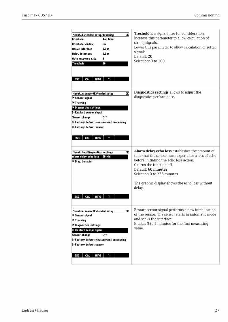
Treshold is a signal filter for consideration.Increase this parameter to allow calculation of strong signals.Lower this parameter to allow calculation of softer signals.Default: 20Selection: 0 to 100.
Diagnostics settings allows to adjust the diagnostics performance.
Alarm delay echo loss establishes the amount of time that the sensor must experience a loss of echo before initiating the echo loss action.0 turns the function off.Default: 60 minutesSelection 0 to 255 minutes
The graphic display shows the echo loss without delay.
Restart sensor signal performs a new initialization of the sensor. The sensor starts in automatic mode and seeks the interface.It takes 3 to 5 minutes for the first measuring value.

Commissioning Turbimax CUS71D
28 Endress+Hauser
If Sensor change is set to "on", the measured value at the current output is set to hold. In this way you avoid an error being reported at the process control system if the sensor is replaced on site.
• Factory default measurement processingReset transmitter parameters to factory default settings.
• Factory default sensorReset sensor parameters to factory default settings.

Turbimax CUS71D Diagnostics and troubleshooting
Endress+Hauser 29
7 Diagnostics and troubleshootingYou must take the entire measuring point into account when troubleshooting:• Transmitter• Electrical connections and cables• Assembly• Sensor
The possible causes of error indicated in the table below primarily refer to the sensor.
Please observe the troubleshooting instructions provided in the transmitter operating manual. Examine the transmitter if necessary.
Problem Check Remedial measures
Nothing displayed, no reaction from the sensor
Power supplied to the transmitter?Sensor connected correctly?Buildup on sensor membrane?
Connect the mains voltageConnect sensor correctlyClean sensor
Display value too high or too low
Buildup on sensor membrane?Check basin configuration.
CleanAdjust
Display value fluctuates a lot
Check mounting location.Buildup on sensor membrane?Check basin configuration.
Select other mounting locationCleanAdjust

Maintenance Turbimax CUS71D
30 Endress+Hauser
8 MaintenanceYou have to perform maintenance tasks at regular intervals.We recommend setting the maintenance times in advance in an operations journal or log.The maintenance cycle primarily depends on the system, the installation conditions and the medium in which measurement takes place.
8.1 Cleaning the sensorSensor without wiperSensor fouling can affect the measurement results and even cause a malfunction.The sensor must be cleaned at regular intervals to ensure reliable measurement results. The frequency and intensity of the cleaning process depends on the medium.
Clean the sensor:• As specified in the maintenance schedule• Before every calibration• Before returning the sensor for repair
You must rinse the sensor thoroughly with water after cleaning.
Sensor with wiperThe time interval is selectable via software. The cleaning time interval depends on the medium. It is recommended to replace the wiper once a year.

Turbimax CUS71D Repair
Endress+Hauser 31
9 Repair
9.1 Spare partsThe following spare part kits are available for the sensor with wiper:
9.2 ReturnThe device must be returned if repairs or a factory calibration are required, or if the wrong device has been ordered or delivered. According to legal regulations, Endress+Hauser, as an ISO-certified company, is required to follow certain procedures when handling returned products that are in contact with medium.
To ensure swift, safe and professional device returns, please read the return procedures and conditions on the internet site:www.services.endress.com/return-material
9.3 DisposalThe device contains electronic components and must therefore be disposed of in accordance with regulations on the disposal of electronic waste.Please observe local regulations.
Description and kit content Order number
Wiper assembly
• rubber blade• plastic housing
71156817
Motor assembly
• gear motor• motor cable
71156830
Coupler assembly
• set screw• non-metallic coupler
71156832
Shaft assembly
• bushing• o-ring• shaft• washer/spacer
71156833

Accessories Turbimax CUS71D
32 Endress+Hauser
10 Accessories
10.1 AssembliesWastewater assembly Flexdip CYA112• Modular assembly system for sensors in open basins, channels and tanks• Versions in stainless steel or PVC• Ordering per product structure (--> Online configurator: www.products.endress.com/
cya112)• Technical Information TI00432C/07/EN
PVC protector for flexible mounting of CUS71D• The PVC protector protects the ultrasonic sensor from getting damaged by the surface
skimmer.• Order number: 71178584
a0016892
Fig. 10: PVC protector for CUS71D
1 Assembly CYA1122 PVC-protector3 Ultrasonic sensor CUS71D
10.2 HolderHolder system Flexdip CYH112 for water• Modular holder system for sensors and assemblies in open basins, channels and tanks• The holder system CYH112 works for nearly any type of fixing - fixing on the floor, wall or
directly on a rail.• Material: stainless steel• Ordering acc. to product structure (--> Online configurator: www.products.endress.com/
cyh112)• Technical Information TI00430C/07/EN
271 (
10.6
7)
Ø 99 (3.9)
44
(1.7
3)
129 (
5.0
8)
Ø 74.3
(2.93)
Ø 41 (1.61)
1
2
3
mm (inch)

Turbimax CUS71D Accessories
Endress+Hauser 33
10.3 TransmitterLiquiline CM442/CM444/CM448• Multiple-channel transmitter for the connection of digital sensors with Memosens
technology• Power supply: 100 to 230 V AC, 24 V AC/DC• Universally upgradeable• SD card slot• Alarm relay• IP 66, IP67, NEMA 4X• Ordering per product structure (--> Online configurator on product page)
10.4 Cable extensionCYK11 Memosens data cable• Extension cable for digital sensors with Memosens protocol• Ordering as per product structure (--> Online configurator, www.products.endress.com/
cyk11)
Junction box cable/cable• Material: aluminum, painted• Cable extension: Memosens sensors, Liquiline• Order no. 71145499

Technical Data Turbimax CUS71D
34 Endress+Hauser
11 Technical Data
11.1 Input
11.2 Performance characteristics
11.3 Environment
11.4 Process
11.5 Mechanical construction
Measured variable Standard sensor Interface
Sensor with wiper Interface
Measuring ranges Standard sensor 0.3 to 10.0 m (1.0 to 32 ft)
Sensor with wiper 0.3 to 10.0 m (1.0 to 32 ft)
Measured error Interface 35 mm at 3.0 m
Wavelength Interface 3 mm at 3.0 m
Measuring interval Sensor internal adjustable
Sensor to transmitter 12 s
Calibration The sensor is factory calibrated delivered. The "speed of sound" is adjustable and pre-programmed for the application "water".
Storage temperature -20 to 50 °C (-4 to 122 °F)
Degree of protection IP 68 (test conditions: 1 m (3.3 ft) water column during 60 days, 1 mol/l KCl)
Process temperature range
1 to 50 °C (34 to 122 °F)
Process pressure 0.0 to 6 bar (0 to 87 psi) absolute
Dimensions See "Installation conditions"
Weight Standard sensor 1.02 kg (2.25 lb)
Sensor with wiper 1.25 kg (2.75 lb)
Materials Sensor ABS and epoxy plastic
Wiper Rubber
Process connections G1 and NPT ¾''

Turbimax CUS71D Technical Data
Endress+Hauser 35

Turbimax CUS71D
36 Endress+Hauser
Index
AAccessories . . . . . . . . . . . . . . . . . . . . . . . . . . . . . . . . . . . . . 32Assemblies . . . . . . . . . . . . . . . . . . . . . . . . . . . . . . . . . . . . . 32
BBasic settings . . . . . . . . . . . . . . . . . . . . . . . . . . . . . . . . . . . 16
CCable extension . . . . . . . . . . . . . . . . . . . . . . . . . . . . . . . . . 33Checking
Installation . . . . . . . . . . . . . . . . . . . . . . . . . . . . . . . . . . 11Cleaning . . . . . . . . . . . . . . . . . . . . . . . . . . . . . . . . . . . . . . . 30Commissioning . . . . . . . . . . . . . . . . . . . . . . . . . . . . . . . . . 16Compressed air cleaning. . . . . . . . . . . . . . . . . . . . . . . . . . 15Connection
Transmitter. . . . . . . . . . . . . . . . . . . . . . . . . . . . . . . . . . 12
DDeclaration of conformity. . . . . . . . . . . . . . . . . . . . . . . . . . . 6Designated use. . . . . . . . . . . . . . . . . . . . . . . . . . . . . . . . . . . . 4Diagnostics . . . . . . . . . . . . . . . . . . . . . . . . . . . . . . . . . . . . . 29Dimensions. . . . . . . . . . . . . . . . . . . . . . . . . . . . . . . . . . . . . . . 7Disposal. . . . . . . . . . . . . . . . . . . . . . . . . . . . . . . . . . . . . . . . 31
EElectrical connection . . . . . . . . . . . . . . . . . . . . . . . . . . . . . 12
FFactory settings . . . . . . . . . . . . . . . . . . . . . . . . . . . . . . . . . 15Firmware update . . . . . . . . . . . . . . . . . . . . . . . . . . . . . . . . 16Function . . . . . . . . . . . . . . . . . . . . . . . . . . . . . . . . . . . . . . . 14
HHolder . . . . . . . . . . . . . . . . . . . . . . . . . . . . . . . . . . . . . . . . . 32
IIncoming acceptance . . . . . . . . . . . . . . . . . . . . . . . . . . . . . . . 6Installation . . . . . . . . . . . . . . . . . . . . . . . . . . . . . . . . . . . . 7–8Installation conditions . . . . . . . . . . . . . . . . . . . . . . . . . . . 10
MMaintenance . . . . . . . . . . . . . . . . . . . . . . . . . . . . . . . . . . . 30Measuring principle . . . . . . . . . . . . . . . . . . . . . . . . . . . . . 14Measuring system . . . . . . . . . . . . . . . . . . . . . . . . . . . . . . . . . 8
NNameplate . . . . . . . . . . . . . . . . . . . . . . . . . . . . . . . . . . . . . . . 6
OOperational safety . . . . . . . . . . . . . . . . . . . . . . . . . . . . . . . . . 4
PParametrization . . . . . . . . . . . . . . . . . . . . . . . . . . . . . . . . . 15Post-connection check . . . . . . . . . . . . . . . . . . . . . . . . . . . 13Product safety . . . . . . . . . . . . . . . . . . . . . . . . . . . . . . . . . . . . 5
RRepair . . . . . . . . . . . . . . . . . . . . . . . . . . . . . . . . . . . . . . . . . . 31Requirements for the personnel . . . . . . . . . . . . . . . . . . . . . 4Return. . . . . . . . . . . . . . . . . . . . . . . . . . . . . . . . . . . . . . . . . . 31
SScope of delivery . . . . . . . . . . . . . . . . . . . . . . . . . . . . . . . . . . 6Sensor
Monitoring . . . . . . . . . . . . . . . . . . . . . . . . . . . . . . . . . . . 14Sensor design. . . . . . . . . . . . . . . . . . . . . . . . . . . . . . . . . . . . 14Settings. . . . . . . . . . . . . . . . . . . . . . . . . . . . . . . . . . . . . . . . . 16Software . . . . . . . . . . . . . . . . . . . . . . . . . . . . . . . . . . . . . . . . 16Spare parts . . . . . . . . . . . . . . . . . . . . . . . . . . . . . . . . . . . . . . 31
TTechnical Data . . . . . . . . . . . . . . . . . . . . . . . . . . . . . . . . . . . 34Transmitter . . . . . . . . . . . . . . . . . . . . . . . . . . . . . . . . . . . . . 33Transmitter connection . . . . . . . . . . . . . . . . . . . . . . . . . . . 12Troubleshooting . . . . . . . . . . . . . . . . . . . . . . . . . . . . . . . . . 29
UUse . . . . . . . . . . . . . . . . . . . . . . . . . . . . . . . . . . . . . . . . . . . . . 4
WWorkplace safety. . . . . . . . . . . . . . . . . . . . . . . . . . . . . . . . . . 4


www.addresses.endress.com
71209086


![Q ;¤CeW27m[oRek¨Uì]Ë. .÷ Endress+Hauser * 2Ý...Endress+Hauser 中国 鸟瞰图 Endress+Hauser 工程师在现场 4 Q ;£CdW17l[nRdk Uë]Ê. .ö Endress+Hauser * 2Ý5 Endress+Hauser](https://static.fdocuments.net/doc/165x107/61269abbaa2e0357dc52fda9/q-cew27moreku-endresshauser-2-endresshauser-ec.jpg)


