OPERATING INSTRUCTIONS LINE ARRAY … · LINE ARRAY SPEAKERS RIGGING FRAME RIGGING SUPPORT BRACKET...
32
OPERATING INSTRUCTIONS Note that casters must be prepared separately. Thank you for purchasing TOA Line Array Speaker. Please carefully follow the instructions in this manual to ensure long, trouble-free use of your equipment. LINE ARRAY SPEAKERS RIGGING FRAME RIGGING SUPPORT BRACKET TILT JOINT BRACKET CLUSTER BRACKET SR-C8L SR-C8S SR-C15B SR-RF8 SR-SB8 SR-TP8 SR-CL8
-
Upload
truongquynh -
Category
Documents
-
view
229 -
download
0
Transcript of OPERATING INSTRUCTIONS LINE ARRAY … · LINE ARRAY SPEAKERS RIGGING FRAME RIGGING SUPPORT BRACKET...
OPERATING INSTRUCTIONS
Note that casters must be prepared separately.
Thank you for purchasing TOA Line Array Speaker.Please carefully follow the instructions in this manual to ensure long, trouble-free use of your equipment.
LINE ARRAY SPEAKERS
RIGGING FRAMERIGGING SUPPORT BRACKETTILT JOINT BRACKETCLUSTER BRACKET
SR-C8LSR-C8SSR-C15B
SR-RF8SR-SB8SR-TP8SR-CL8

TABLE OF CONTENTS
2
1. SAFETY PRECAUTIONS ............................................................................................... 3
2. GENERAL DESCRIPTION ............................................................................................. 5
3. FEATURES .......................................................................................................................... 5
4. INSTALLATION PRECAUTIONS ................................................................................. 5
5. DIMENSIONAL DIAGRAMS5.1. Speaker Systems
5.1.1. SR-C8L Line array speaker ................................................................................... 65.1.2. SR-C8S Line array speaker .................................................................................. 6
5.2. Sub-Woofer Speaker System5.2.1. SR-C15B Line array speaker ................................................................................ 7
5.3. Frame and Brackets5.3.1. SR-RF8 Rigging frame .......................................................................................... 75.3.2. SR-SB8 Rigging support bracket .......................................................................... 85.3.3. SR-TP8 Tilt joint bracket ....................................................................................... 85.3.4. SR-CL8 Cluster bracket ........................................................................................ 8
6. BI-AMPLIFIER AND SINGLE-AMPLIFIER OPERATIONS6.1. Bi-Amplifier Operation ...................................................................................................... 96.2. Single-Amplifier Operation ............................................................................................... 9
7. SWITCHING TO SINGLE-AMPLIFIER OPERATION MODE ............................ 10
8. DIGITAL PROCESSOR SETTINGS8.1. SR-C8L and SR-C8S Systems ....................................................................................... 118.2. Combined SR-C8L or SR-C8S and SR-C15B Systems ................................................. 12
9. FLYING SYSTEMS USING THE SR-RF8 RIGGING FRAME9.1. Flying System Outline .................................................................................................... 139.2. Assembling the SR-RF8 Rigging Frame ........................................................................ 159.3. Connecting the Rigging Frame to the Speaker .............................................................. 169.4. Connection Between Speakers ...................................................................................... 179.5. About the Flying Installations ......................................................................................... 18
10. INSTALLING THE FLYING SYSTEM USING THE SR-CL8 CLUSTER BRACKET10.1. Flying System Outline .................................................................................................. 1910.2. Vertical Flying Installation ............................................................................................. 1910.3. Horizontal Flying ........................................................................................................... 21
11. SPEAKER STACKING11.1. Stack System Outline .................................................................................................... 2311.2. Assembling the SR-RF8 Rigging Frame ....................................................................... 2411.3. Connecting the Rigging Frame to the Speaker ............................................................. 2511.4. Connections Between Speakers ................................................................................... 2511.5. About Stacking ............................................................................................................. 26
12. USING THE SR-SB8 RIGGING SUPPORT BRACKET ...................................... 2712.1. Level Adjuster Installation ............................................................................................ 2712.2. Rigging Support Bracket Installation ............................................................................ 2712.3. Frequent Attachment and Detachment of the Rigging Support Bracket ...................... 2812.4. Adjust the Height With a Level Adjuster to Prevent Unstable Installation .................... 28
13. TILTING THE SPEAKER DOWNWARD .................................................................. 29
14. SPECIFICATIONS14.1. SR-C8L and SR-C8S .................................................................................................... 3014.2. SR-C15B ....................................................................................................................... 3014.3. SR-RF8 ......................................................................................................................... 3114.4. SR-SB8 ......................................................................................................................... 3114.5. SR-TP8.......................................................................................................................... 3114.6. SR-CL8 ......................................................................................................................... 31

1. SAFETY PRECAUTIONS
3
When Installing the Unit
• Avoid installing or mounting the unit in unstablelocations, such as on a rickety table or a slantedsurface. Doing so may result in the unit fallingdown and causing personal injury and/or propertydamage.
• Refer all installation work to the dealer from whomthe speaker was purchased. Installation for flyingrequires extensive technical knowledge andexperience. The speaker may fall off if incorrectlyinstalled, resulting in possible personal injury.
• Flying precautions. Be sure to follow the instructions below. Otherwise,the suspension wires or belts may be off or snapand the speaker may fall off, causing personalinjury.· Check to confirm that the suspension wires and
belts are strong enough to · The connectors of the suspension wires and belts
must be securely l inked with those of thespeaker.
· All parts and components (such as enclosures,metal pieces, and screws) must be free from anydeformation, crack, and corrosion.
· Be sure to use screws supplied with the optionalflying hardware when installing the speaker usingsuch hardware.
• Install the unit only in a location that canstructurally support the weight of the unit and themounting bracket. Doing otherwise may result inthe unit falling down and causing personal injuryand/or property damage.
• Since the unit is designed for in-door use, do notinstall it outdoors. If installed outdoors, the aging ofparts causes the unit to fall off, resulting in personalinjury. Also, when it gets wet with rain, there is adanger of electric shock.
• Owing to the unit's size and weight, be sure that atleast two persons are available to install the unit.Failure to do so could result in personal injury.
When Installing the Unit
• Do not use other methods than specified to mountthe bracket. Extreme force is applied to the unitand the unit could fall off, possibly resulting inpersonal injuries.
• Use nuts and bolts that are appropriate for theceiling's or wall's material and structure. Failure todo so may cause the unit to fall, resulting inmaterial damage and possible personal injury.
• Tighten each nut and bolt securely. Ensure that thebracket has no loose joints after installation toprevent accidents that could result in personalinjury.
• Use the specified mounting bracket in combination.Doing otherwise may cause the unit or componentto fall off, resulting in personal injury.
• Do not mount the unit in locations exposed toconstant vibration. The mounting bracket can bedamaged by excessive vibration, potentiallycausing the unit to fall, which could result inpersonal injury.
• Do not install the unit in indoor swimming pools orsuch locations where corrosion may occur easily.The parts deteriorate if corroded, causing the unitto fall, which could result in personal injury.
• Be sure to read this safety instructions in this section carefully in prior to use.• Be sure to follow all the precautionary instructions in this section, which contain important warnings and/or
cautions regarding safety.• After reading, keep this manual handy for future reference.
Safety Symbol and Message ConventionsSafety symbols and messages described below are used in this manual to prevent bodily injury and propertydamage which could result from mishandling. Before operating your product, read this manual first andunderstand the safety symbols and messages so you are thoroughly aware of the potential safety hazards.
WARNING
Indicates a potentially hazardous situation which, if mishandled, couldresult in death or serious personal injury.
Indicates a potentially hazardous situation which, if mishandled, couldresult in moderate or minor injury, and/or property damage.
WARNING
CAUTION

4
When the Unit is in Use
• Do not place heavy objects on the unit as this maycause it to fall or break which may result inpersonal injury and/or property damage. Inaddition, the object itself may fall off and causeinjury and/or damage.
• Do not operate the unit for an extended period oftime with the sound distorting. Doing so may causethe connected speakers to heat, resulting in a fire.
• Do not stand or sit on, nor hang down from the unitas this may cause it to fall down or drop, resultingin personal injury and/or property damage.
• To avoid risks, warn others to stay away from thespeaker or not to lean against it. Otherwise peoplemay trip over a Rigging Support Bracket or thespeaker may fall down, causing personal injury.
• Have the unit checked periodically by the shopfrom where it was purchased. Failure to do so mayresult in corrosion or damage to the speaker or theunit that could cause it to fall, possibly causingpersonal injury.
CAUTION
2. GENERAL DESCRIPTION
3. FEATURES
4. INSTALLATION PRECAUTIONS
5
TOA's lineup of line array speakers employs TOA's unique wave front control technology to create a soundfield that offers clear reproduction and uniform sound dispersion. This lineup includes versions offering either 5 degrees or 15 degrees of angled vertical directivity, as well assub-woofer configured types. The use of optional support brackets allows the line array speakers to be used in many applications aspermanent sound system installations.
• TOA's unique wave front control technology creates a uniform sound distribution field with interference-freehigh frequency output, realizing high-clarity acoustic characteristics and long sound transmissioncapabilities.
• The SR-C8L is a two-way speaker mounting a high-power 20 cm woofer and two compression drivers, andfeaturing a 5 degree angle of vertical directivity and 110 degrees of horizontal. It is ideal for long distanceapplications and can be powered by either one or two amplifiers.
• The SR-C8S is a two-way speaker mounting a high-power 20 cm woofer and two compression drivers, andfeaturing a 15 degree angle of vertical directivity and 110 degrees of horizontal. It is ideal for shorterdistance applications and can be powered by either one or two amplifiers.
• By combining the long-distance SR-8L and short-distance SR-8S, a line array speaker system can be builtto support a variety of applications.
• The SR-C15B sub-woofer employs a large-diameter 38 cm woofer with high power handling capabilities,and is designed to be used in conjunction with the SR-C8L or SR-C8S line array speakers.
• The line array speakers are designed to allow easy rear access for maintenance work.
• Overlap angles between individual speakers can be set in 1 degree units between 0 and 5 degrees whenconstructing the line array speaker, making it possible to flexibly control speaker directivity.
• The line array speaker can be stacked or suspended with the additional use of the SR-RF8 Rigging Frame.
Since this speaker system is designed exclusively for indoor use, be sure to install it only in locations isolatedfrom weather and temperature extremes. Also, to prevent equipment malfunctions, do not install the speaker in locations exposed to both hightemperatures and high humidity, such as indoor swimming pool facilities.
5. DIMENSIONAL DIAGRAMS
6
5.1. Speaker Systems
5.1.1. SR-C8L Line array speaker
(Front view) (Left side view)
Unit: mm
(Rear view)
(Right side view)
526.6 [20.73"]470 [18.5"]
5°
293
[11.
54"]
259.
6 [1
0.22
"]
296 [11.65"]
5.1.2. SR-C8S Line array speaker
(Front view)(Left side view)
Unit: mm
(Rear view)
(Right side view)
470 [18.5"]
526.6 [20.73"]
15°
258.
8 [1
0.19
"]
293
[11.
53"]
294 [11.57"]

7(Bottom view)
(Left side view)
Unit: mm
(Top view)
(Front view)
(Right side view)
16-M10(For caster mounting)
15-ø20 [ø0.79"]
14 [0.55"]
6 [0.24"] 498 [19.61"]
510 [20.08"]377 [14.84"]
93 [3
.66"
]36
[1.4
2"]
25 [0.98"]
71 [2
.8"]
95 [3
.74"
]
71 [2.8"]
95 [3.74"]
50 [1
.97"
]4.
5 [0
.18"
]
6.4 [0.25"]
50 [1
.97"
]
155.5 [6.12"]
690
[27.
17"]
595
[23.
43"]
85 [3
.35"
]
167 [6.58"]
105 [4.13"]
5.3. Frame and Brackets
5.3.1. SR-RF8 Rigging frame
(Front view)(Left side view)
Unit: mm
(Rear view)
(Right side view)
526.6 [20.73"]
470 [18.5"]
540
[21.
26"]
594.
8 [2
3.42
"]
550 [21.65"]
5.2. Sub-Woofer Speaker System
5.2.1. SR-C15B Line array speaker
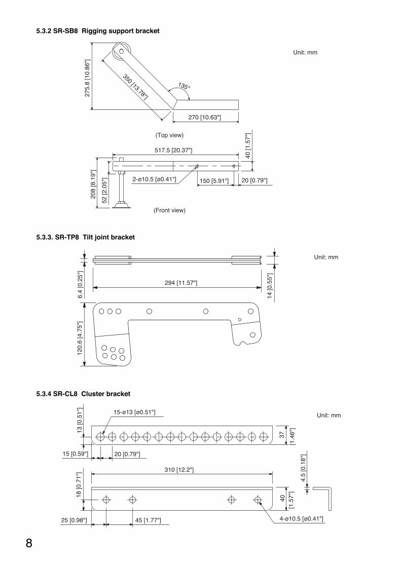
8
Unit: mm
4-ø10.5 [ø0.41"]
15-ø13 [ø0.51"]
[1.4
6"]
[1.5
7"]
3740
13 [0
.51"
]
45 [1.77"]25 [0.98"]
18 [0
.71"
]
15 [0.59"] 20 [0.79"]
310 [12.2"]
4.5
[0.1
8"]
5.3.4 SR-CL8 Cluster bracket
Unit: mm
120.
6 [4
.75"
]6.
4 [0
.25"
]
294 [11.57"]
14 [0
.55"
]
5.3.3. SR-TP8 Tilt joint bracket
(Front view)
Unit: mm
(Top view)
2-ø10.5 [ø0.41"]
517.5 [20.37"]
52 [2
.05"
]
208
[8.1
9"]
275.
8 [1
0.86
"]
350 [13.78"]
40 [1
.57"
]
150 [5.91"] 20 [0.79"]
270 [10.63"]
135°
5.3.2 SR-SB8 Rigging support bracket

6. BI-AMPLIFIER AND SINGLE-AMPLIFIER OPERATIONS
9
The SR-C8 series speakers are supplied from the factory set up for bi-amplifier operation. However, thisdefault specification can be switched to single-amplifier operation mode by simply changing the position of aninternal connector. (Refer to page 10. "Switching to Single-Amplifier Operation Mode")
6.1. Bi-Amplifier Operation
6.1.1. System diagram
Mixer/preamplifier
Digitalprocessor
Power amplifier
Passivenetwork
SR-C8L/C8S
LOW
HIGH
Tweeter
Woofer
Passivenetwork Woofer
Tweeter
Screw terminalNeutrik NL4MP connector
Input terminal panel
INPUT
INPUT
THROUGH
THROUGH2
1
1
2
1
2 12
Mixer/preamplifier
Digitalprocessor
Power amplifier
SR-C8L/C8S
LOW
HIGH
LOW
HIGH
Tweeter
Woofer
LOW
HIGH
LOW
HIGH2
1
2 1
2
1
2 1
Screw terminalNeutrik NL4MP connector
Input terminal panel
Woofer
Tweeter
6.2. Single-Amplifier Operation
6.2.1. System diagram
6.1.2. Internal wiring diagram
6.2.2. Internal wiring diagram

7. SWITCHING TO SINGLE-AMPLIFIER OPERATION MODE
10
To switch the speaker's bi-amplifier operation mode to single-amplifier operation, remove the speaker's rearinput panel and change the speaker's internal wiring.
Switching Power Modes
Step 1. Remove the four screws securing the input terminal panel and pull out the panel.
Step 2. Pull out a short length of the wiring connected to the back side of the input panel.
Step 3. Disconnect and switch the two pairs of connected connectors so that the two marked and unmarkedconnector halves match up.
Step 4. Reinstall the input terminal panel using the four removed screws.
Step 5. Attach the supplied seals to the input terminal panel to change the indication.
Switching connectors
Mark
Input indication seal for single-amplifier operation (accessory)
Rating seal for single-amplifieroperation (accessory)
Changing input terminal panel indication
Panel mounting screws
Input terminal panel
1, 4 2
3
5

8. DIGITAL PROCESSOR SETTINGS
11
Set the digital processor's parameters as follows:
8.1.2. Single-amplifier operation
8.1. SR-C8L and SR-C8S Systems
8.1.1. Bi-amplifier operation
ChannelGain(dB)
PolarityDelay(msec)TYPE Freq. (Hz)
Filter
Gain (dB) Q
PEQ 280 3.5 4.318
PEQ 800 2.0 3.450
PEQ 2.5k 11.5 1.044SR-C8
PEQ 2.65k 5.0 2.145
PEQ 5.3k 2.5 1.204
HPF (12 dB) 60 1.000
PEQ 9.0k 6.0 1.707
0Normal
(Positive)
Channel
0Normal
(Positive)
Normal(Positive)
Gain(dB)
PolarityDelay(msec)TYPE Freq. (Hz)
Filter
Gain (dB) Q
–9.0
PEQ 1.6k –4.0 1.414
SR-C8LOW
LPF (12 dB) 2.0k 0.7070.667HPF (12 dB) 60 1.000
PEQ 800 –5.0 3.450
HPF (12 dB) 2.0k 0.707
PEQ 1.45k 6.0 4.318
PEQ 2.9k 10.0 2.997
SR-C8HIGH
High Shelving 10k 7.0
All Pass 4.5k 2.0160
All Pass 7.6k 2.016
All Pass 11.5k 2.215
All Pass 12.0k 2.016
All Pass 14.0k 1.512
All Pass 17.0k 4.938
Pre-stage Filter
The “Gain” indications are merely provided as guidelines and may need be adjusted depending on the system configuration.
12
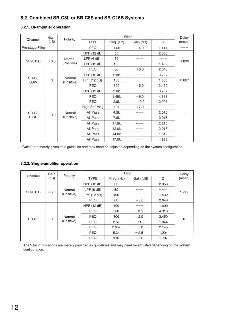
8.2.2. Single-amplifier operation
8.2. Combined SR-C8L or SR-C8S and SR-C15B Systems
8.2.1. Bi-amplifier operation
ChannelGain(dB)
Polarity Delay(msec)TYPE Freq. (Hz)
Filter
Gain (dB) Q
HPF (12 dB) 35 2.053
SR-C15B 6.0Normal
(Positive)LPF (6 dB) 50
1.229LPF (12 dB) 100 1.432
PEQ 60 3.0 2.648
PEQ 280 3.5 4.318
PEQ 800 2.0 3.450
PEQ 2.5k 11.5 1.044SR-C8 0
Normal(Positive)
PEQ 2.65k 5.0 2.145
0
PEQ 5.3k 2.5 1.204
HPF (12 dB) 100
The “Gain” indications are merely provided as guidelines and may need be adjusted depending on the system configuration.
1.000
PEQ 9.0k 1.7076.0
ChannelGain(dB)
Polarity Delay(msec)TYPE Freq. (Hz)
Filter
Gain (dB) Q
“Gains” are merely given as a guideline and may need be adjusted depending on the system configuration.
Pre-stage Filter PEQ 1.6k 4.0 1.414
HPF (12 dB) 35 2.053
6.0Normal
(Positive)LPF (6 dB) 50
1.896SR-C15BLPF (12 dB) 100 1.432
PEQ 60 3.0 2.648
0Normal
(Positive)
Normal(Positive)
LPF (12 dB) 2.0k 0.707
0.667SR-C8LOW HPF (12 dB) 100
PEQ 800 5.0 3.450
HPF (12 dB) 2.0k 0.707
PEQ 1.45k 6.0 4.318
PEQ 2.9k 10.0 2.997
High Shelving 10k 7.0
9.0All Pass 4.5k 2.016
0All Pass 7.6k 2.016
All Pass 11.5k 2.215
All Pass 12.0k 2.016
All Pass 14.0k 1.512
All Pass 17.0k 4.938
SR-C8HIGH
1.000

9. FLYING SYSTEMS USING THE SR-RF8 RIGGING FRAME
13
9.1. Flying System Outline
Use the SR-RF8 Rigging Frame for flying applications. Up to twelve line array speakers can be simultaneouslyconnected per frame, however the SR-C15B is calculated as two units.Adjust the vertical directivity angle according to the installation environment. For applications that specify long-distance sound transmission, link the long-distance SR-C8L speakers together.Shown below is a basic flying system.
SR-C8S
Rigging frame
SR-C15B
SR-C8L
The line array speaker's vertical directivity angle is 5 degrees for the SR-C8L and 15 degrees for the SR-C8S.
5 degrees 15 degrees
[SR-C8L] [SR-C8S]
14
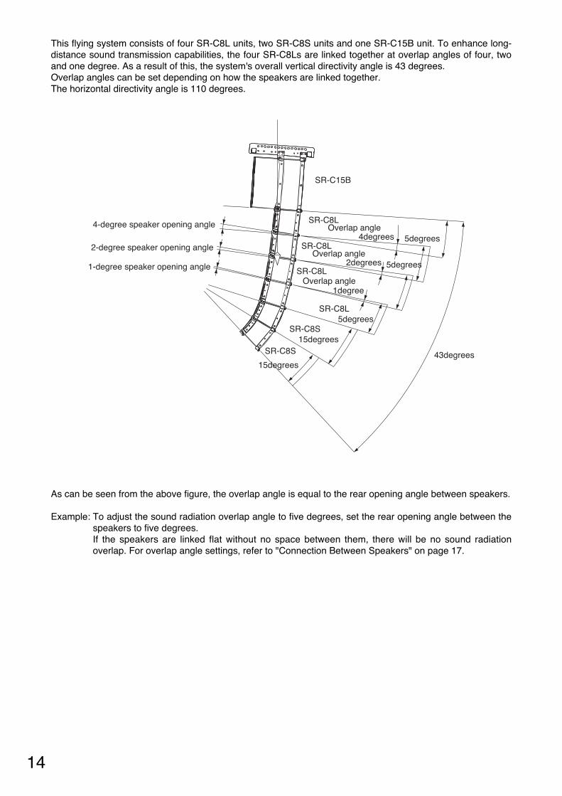
This flying system consists of four SR-C8L units, two SR-C8S units and one SR-C15B unit. To enhance long-distance sound transmission capabilities, the four SR-C8Ls are linked together at overlap angles of four, twoand one degree. As a result of this, the system's overall vertical directivity angle is 43 degrees. Overlap angles can be set depending on how the speakers are linked together. The horizontal directivity angle is 110 degrees.
4-degree speaker opening angle
2-degree speaker opening angle
1-degree speaker opening angle
43degreesSR-C8S
SR-C8S
SR-C8L
SR-C15B
SR-C8L
SR-C8L
SR-C8L
15degrees
15degrees
5degrees
5degrees
5degrees
Overlap angle
Overlap angle
Overlap angle 4degrees
2degrees
1degree
As can be seen from the above figure, the overlap angle is equal to the rear opening angle between speakers.
Example: To adjust the sound radiation overlap angle to five degrees, set the rear opening angle between thespeakers to five degrees. If the speakers are linked flat without no space between them, there will be no sound radiationoverlap. For overlap angle settings, refer to "Connection Between Speakers" on page 17.
15
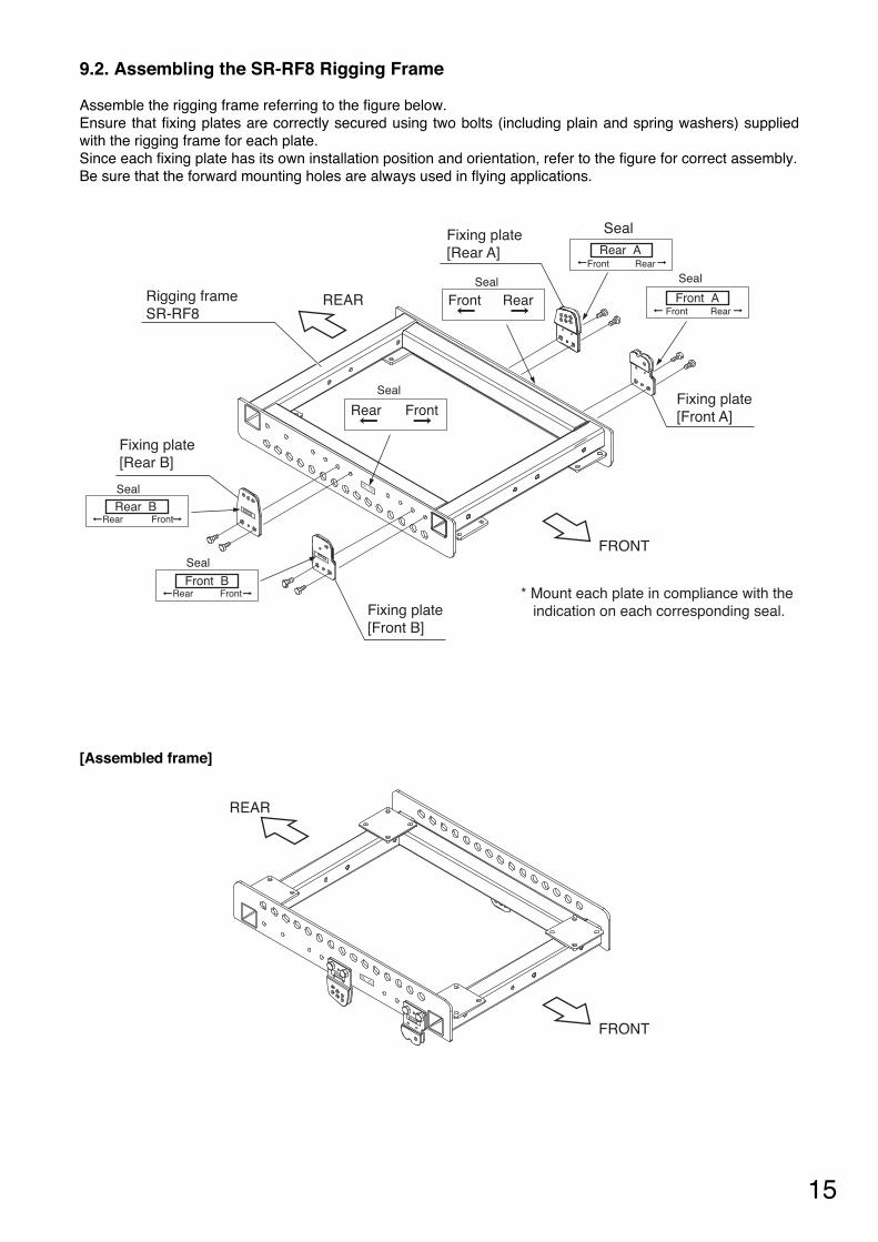
9.2. Assembling the SR-RF8 Rigging Frame
Assemble the rigging frame referring to the figure below.Ensure that fixing plates are correctly secured using two bolts (including plain and spring washers) suppliedwith the rigging frame for each plate. Since each fixing plate has its own installation position and orientation, refer to the figure for correct assembly.Be sure that the forward mounting holes are always used in flying applications.
FRONT
REAR
Fixing plate[Rear B]
Fixing plate[Front B]
Fixing plate[Front A]
Fixing plate[Rear A]
Rigging frame SR-RF8
* Mount each plate in compliance with the indication on each corresponding seal.
Seal
Seal
Seal
Seal
Seal
Seal
FrontRear
Front
Rear
RearFront
Rear AFront Rear
Front ARearFront
Front BFrontRear
Rear BRear Front
Front B
Front
Rear
Rear B
Rear
Front
FRONT
REAR
Rear
Front
Front AFront
Rear
Rear ARear
Front
[Assembled frame]
16
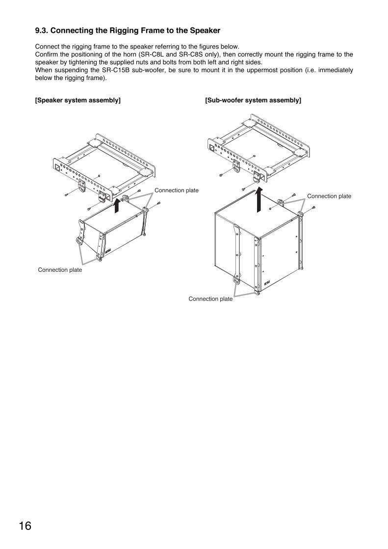
9.3. Connecting the Rigging Frame to the Speaker
Connect the rigging frame to the speaker referring to the figures below.Confirm the positioning of the horn (SR-C8L and SR-C8S only), then correctly mount the rigging frame to thespeaker by tightening the supplied nuts and bolts from both left and right sides. When suspending the SR-C15B sub-woofer, be sure to mount it in the uppermost position (i.e. immediatelybelow the rigging frame).
Connection plate
Connection plate
Connection plate
Connection plate
[Speaker system assembly] [Sub-woofer system assembly]

17
9.4. Connection Between Speakers
Inter-connect speaker sections referring to the figures below.Ensure that both speakers are securely connected by tightening the supplied nuts and bolts from both left andright sides.Since connection holes for setting the overlap angle are provided at the back of the speaker, assemble usingthe connection holes matching the required overlap angle. The overlap angle can be set within the range of 0to 5 degrees in 1 degree units.
Left side connection holes foroverlap angle settings
Left side connectionholes for overlap angle settings
Overlap angle
0degree
1degree
2degrees
5degrees
4degrees
3degrees
3degrees
4degrees
5degrees
2degrees
1degree
0degree
Right side connection holesfor overlap angle settings
Right side connectionholes for overlap angle settings
Front
18
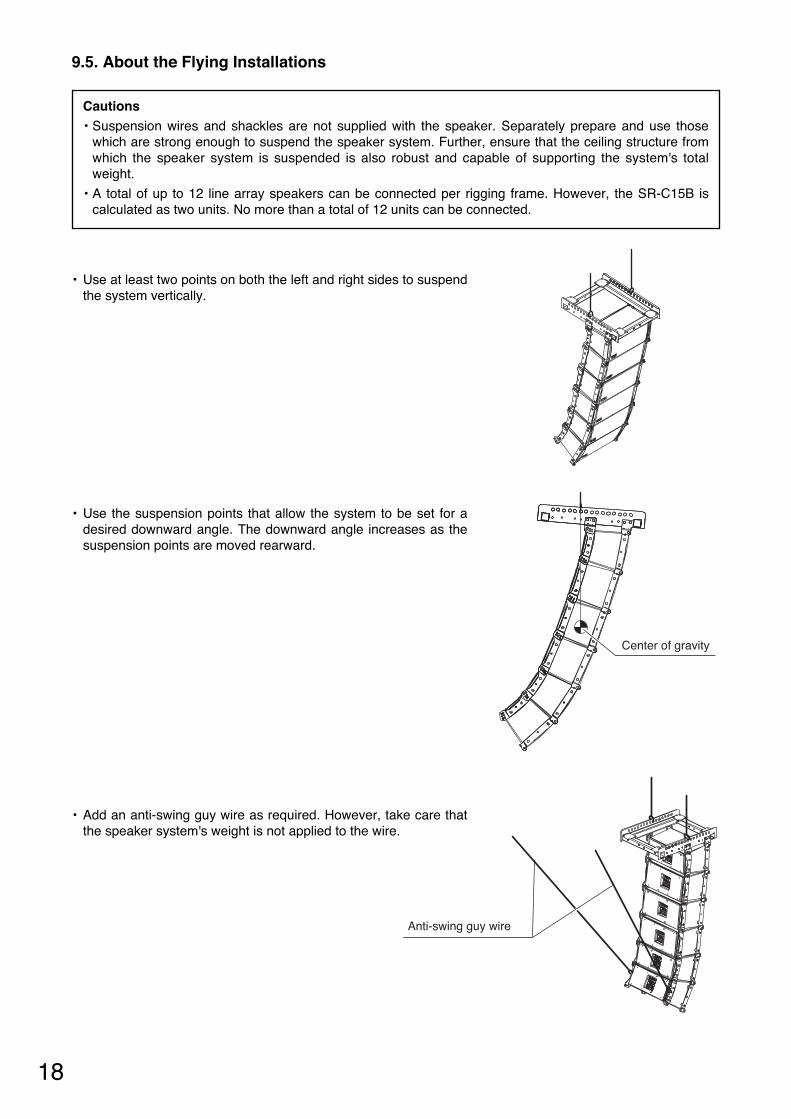
9.5. About the Flying Installations
Center of gravity
Anti-swing guy wire
• Use at least two points on both the left and right sides to suspendthe system vertically.
• Use the suspension points that allow the system to be set for adesired downward angle. The downward angle increases as thesuspension points are moved rearward.
• Add an anti-swing guy wire as required. However, take care thatthe speaker system's weight is not applied to the wire.
Cautions• Suspension wires and shackles are not supplied with the speaker. Separately prepare and use those
which are strong enough to suspend the speaker system. Further, ensure that the ceiling structure fromwhich the speaker system is suspended is also robust and capable of supporting the system's totalweight.
• A total of up to 12 line array speakers can be connected per rigging frame. However, the SR-C15B iscalculated as two units. No more than a total of 12 units can be connected.

10. INSTALLING THE FLYING SYSTEM USING THE SR-CL8 CLUSTER BRACKET
19
10.1. Flying System Outline
This flying system uses the SR-CL8 Cluster Bracket. Using the cluster bracket, up to four speakers can beconnected to each other when suspending in vertical or horizontal orientation. Note that the sub-woofercannot be installed using the cluster bracket.
10.2. Vertical Flying Installation
10.2.1. Cluster bracket attachment
Attach the cluster brackets to the speaker referring to the figure below. Ensure that they are securely attachedwith the supplied nuts and bolts (including plain and spring washers).
Cluster bracketSR-CL8

20
10.2.2. Vertical flying installation
• Use two points on both the left and right sides to suspend the system vertically.
• Use the suspension points that allow the system to be set for a desired downward angle. The downwardangle increases as the suspension points are moved rearward.
Suspension using the forwardsuspension points
Suspension using the rearwardsuspension points
Front Front
Cautions• Wires and shackles to be used for suspension are not supplied with the speaker. Separately prepare and
use those which are strong enough to suspend the speaker system. Further, ensure that the ceilingstructure from which the speaker system is suspended is also robust and capable of standing thesystem's total weight.
• A total of up to four line array speakers can be connected to each other when using this cluster bracketfor suspension.

21
• Add an anti-swing guy wire as required. However, take care that the speaker's weight is not applied to thewire.
Anti-swing guy wire
10.3. Horizontal Flying
10.3.1. Cluster bracket attachment
Attach the cluster brackets to the leftmost and rightmost of the connected speakers referring to the figurebelow. Ensure that they are securely attached with the supplied nuts and bolts (including plain and springwashers).
Cluster bracketSR-CL8

22
10.3.2. Horizontal Flying Installation
• Use at least two left and right points to suspend the system vertically.
• Use the suspension points that allow the system to be set for a desired downward angle. The downwardangle increases as the suspension points are moved rearward.
• Add an anti-swing guy wire as required. However, take care that the speaker system's weight is not appliedto the wire.
Anti-swing guy wire
Cautions• Wires and shackles to be used for suspension are not supplied with the speaker. Separately prepare and
use those which are strong enough to suspend the speaker system. Further, ensure that the ceilingstructure from which the speaker system is suspended is also robust and capable of standing thesystem's total weight.
• A total of up to four line array speakers can be connected to each other when using this cluster bracketfor suspension.

11. SPEAKER STACKING
23
Mount casters of the following specifications, which function as the feet of the rigging frame. Prepare thecasters and caster mounting bolts separately.
[Caster Specifications]Diameter: Over 100 mmMounting pitch: 71 mm x 71 mmMounting bolt (diameter): M10Mounting plate dimensions: 95 mm x 95 mmLoad-bearing capacity: Over 50% x total weight (rigging frame weight + speaker weight) per casterMust be equipped with a stopper.Recommended model: K52S-100 made by Takigen
11.1. Stack System Outline
It is possible to stack the line array speakers using the SR-RF8 Rigging Frame. Up to eight speakers can bestacked, noting that each line array speaker is calculated as 1 unit and each SR-C15B sub-woofer as 2 units.Shown below is a basic stack system. Note that casters must be prepared separately.
Rigging support bracketSR-SB8
SR-C8L
SR-C15B
Casters(Prepare separately.)
Rigging frameSR-RF8

24
11.2. Assembling the SR-RF8 Rigging Frame
Before assembly, first determine whether to set the mounting position of the fixing plate at the center orforward, taking the stack system's center of gravity into consideration.Ensure that fixing plates are correctly secured using two bolts (including plain and spring washers) suppliedwith the rigging frame for each plate. Since each fixing plate has its own installation position and orientation, assemble it referring to the figure.
FRONT
REAR
Fixing plate[Rear B]
Fixing plate[Front B]
Fixing plate[Front A]
Fixing plate[Rear A]
Rigging frameSR-RF8
*Mount each plate in compliance with the indication on its corresponding seal.
Seal
Seal
Seal
Seal
Seal
Seal
FrontRear
Front
Rear
RearFront Front AFront Rear
Rear AFront Rear
Front BRear Front
Rear BRear Front
Rear BRear
Front
Front BRear
Front
Front
Fixing plateFixing plate
When attaching the fixing plate at the center When attaching the fixing plate forward
Attach at the center when the center ofgravity is shifted forward.
Attach forward when the center ofgravity is shifted backward
Front
The center of gravity isshifted backward.
The center of gravity isshifted forward.

25
11.3. Connecting the Rigging Frame to the Speaker
Connect the rigging frame to the speaker referring to the following figure. Correctly connect both units by tightening the supplied nuts and bolts from both the left and right sides. When using the SR-C15B sub-woofer in the stack system, mount it in the lowermost position (i.e. immediatelyabove the rigging frame). In this configuration, attach the sub-woofer receptacle pieces to the rigging frame,as shown in the figure.
Speaker system assembly Sub-woofer system assembly
Sub-wooferreceptacle piece
Sub-wooferreceptacle piece
11.4. Connections Between Speakers
Refer to page 17; "Connection Between Speakers" of the chapter "Flying Systems Using the SR-RF8 RiggingFrame."
26
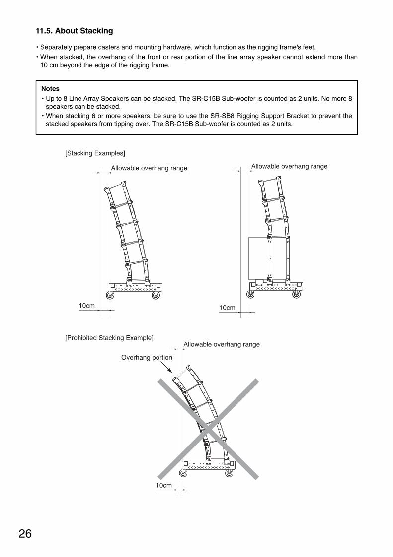
[Stacking Examples]
[Prohibited Stacking Example]
Allowable overhang range
10cm
Allowable overhang range
10cm
Overhang portion
Allowable overhang range
10cm
11.5. About Stacking
• Separately prepare casters and mounting hardware, which function as the rigging frame's feet.
• When stacked, the overhang of the front or rear portion of the line array speaker cannot extend more than10 cm beyond the edge of the rigging frame.
Notes• Up to 8 Line Array Speakers can be stacked. The SR-C15B Sub-woofer is counted as 2 units. No more 8
speakers can be stacked.
• When stacking 6 or more speakers, be sure to use the SR-SB8 Rigging Support Bracket to prevent thestacked speakers from tipping over. The SR-C15B Sub-woofer is counted as 2 units.

12. USING THE SR-SB8 RIGGING SUPPORT BRACKET
27
The SR-SB8 Rigging Support Bracket is used to prevent the stacked SR-C8 series line array speakers fromtipping over. Be sure the SR-SB8 is used whenever six or more SR-C8 series speakers are stacked. Count the SR-C15B sub-woofer as two units when configuring a system.
12.1. Level Adjuster Installation
Mount a level adjuster on each rigging support bracket, referring to the following figure.Turn each level adjuster to adjust the rigging frame height so that the tip of the adjuster projects about 30 mmabove the support bracket.
30mm
12.2. Rigging Support Bracket Installation
Mount the rigging support bracket to the rigging frame, as shown in the figure below. Ensure that all supportbrackets are securely mounted using the supplied nuts and bolts.
Rigging support bracket
Rigging support bracket
Rigging frame
Step 1. Insert the support bracket into the rigging frame.
Step 2. Secure the support bracket using the supplied bolts.
28
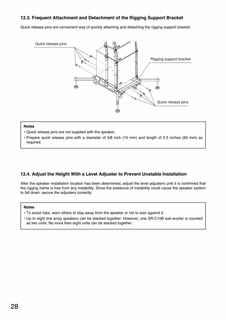
12.3. Frequent Attachment and Detachment of the Rigging Support Bracket
Quick release pins are convenient way of quickly attaching and detaching the rigging support bracket.
Rigging support bracket
Quick release pins
Quick release pins
12.4. Adjust the Height With a Level Adjuster to Prevent Unstable Installation
After the speaker installation location has been determined, adjust the level adjusters until it is confirmed thatthe rigging frame is free from any instability. Since the existence of instability could cause the speaker systemto fall down, secure the adjusters correctly.
Notes• Quick release pins are not supplied with the speaker.
• Prepare quick release pins with a diameter of 3/8 inch (10 mm) and length of 2.5 inches (65 mm) asrequired.
Notes• To avoid risks, warn others to stay away from the speaker or not to lean against it.
• Up to eight line array speakers can be stacked together. However, one SR-C15B sub-woofer is countedas two units. No more than eight units can be stacked together.
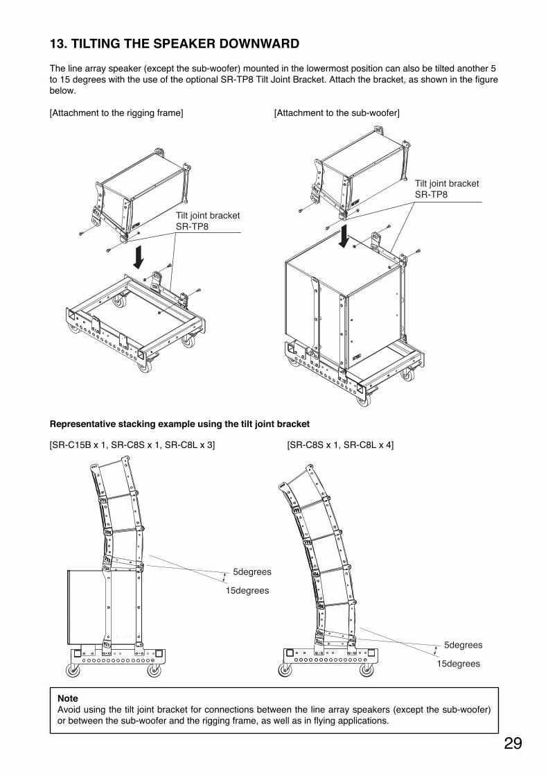
13. TILTING THE SPEAKER DOWNWARD
29
[SR-C8S x 1, SR-C8L x 4]
Tilt joint bracketSR-TP8
Tilt joint bracketSR-TP8
The line array speaker (except the sub-woofer) mounted in the lowermost position can also be tilted another 5to 15 degrees with the use of the optional SR-TP8 Tilt Joint Bracket. Attach the bracket, as shown in the figurebelow.
Representative stacking example using the tilt joint bracket
5degrees
15degrees
5degrees
15degrees
[SR-C15B x 1, SR-C8S x 1, SR-C8L x 3]
NoteAvoid using the tilt joint bracket for connections between the line array speakers (except the sub-woofer)or between the sub-woofer and the rigging frame, as well as in flying applications.
[Attachment to the rigging frame] [Attachment to the sub-woofer]

30
14. SPECIFICATIONS
Model No. SR-C8L SR-C8SEnclosure Bass-reflex typePower Handling Capacity
Continuous program: 360 W (single-amp mode)Low: 360 W, High: 180 W (bi-amp mode)
Rated Impedance 16 Ω (single-amp mode)Low: 16 Ω, High : 16 Ω (bi-amp mode)
Sensitivity 98 dB (1 W , 1 m) (single-amp mode)Low: 95 dB (1 W, 1 m), High: 110 dB (1 W, 1 m) (bi-amp mode)
Frequency Response 65 Hz to 20 kHz*Crossover Frequency 1.6 kHz*Directivity Angle Horizontal: 110°, Vertical: 5° Horizontal: 110°, Vertical: 15°Speaker Component Low frequency: 20 cm (8") cone-type
High frequency: Wave front control horn 110°(horizontal) x 5°(vertical) + compression driver x 2
Low frequency: 20 cm (8") cone-typeHigh frequency: Wave front control horn 110°(horizontal) x 15°(vertical) + compression driver x 2
Input Connector M5 screw terminal, distance between barriers: 12.2 mm (0.48")and Neutrik NL4MP x 2
Finish Enclosure: Plywood, black, urethane paintFront grille: Punched steel plate, black, paint
Dimensions 526.6 (w) x 293 (h) x 296 (d) mm(20.73" x 11.54" x 11.65")
526.6 (w) x 293 (h) x 294 (d) mm(20.73" x 11.54" x 11.57")
Weight 17 kg (37.48 lb) 16 kg (35.27 lb)Accessory M8 connection bolt ...... 4Option Cluster bracket: SR-CL8
Rigging frame: SR-RF8Tilt joint bracket: SR-TP8Digital speaker processor: DP-SP3
* When recommended parameters are applied by the optional digital speaker processor DP-SP3Note: The design and specifications are subject to change without notice for improvement.
14.1. SR-C8L and SR-C8S
14.2. SR-C15B
* When recommended parameters are applied by the optional digital speaker processor DP-SP3Note: The design and specifications are subject to change without notice for improvement.
Enclosure Bass-reflex typePower Handling Capacity
Continuous program: 450 W
Rated Impedance 8 ΩSensitivity 93 dB (1 W, 1 m)Frequency Response 40 to 400 Hz*Crossover Frequency 125 Hz*Speaker Component 38 cm (15") cone-typeInput Connector M5 screw terminal, distance between barriers: 12.2 mm (0.48")
and Neutrik NL4MP x 2Finish Enclosure: Plywood, black, urethane paint
Front grille: Punched steel plate, black, paintDimensions 526.6 (w) x 594.8 (h) x 550 (d) mm (20.73" x 23.42" x 21.65")Weight 41 kg (90.39 lb)Accessory M8 connection bolt ...... 4Option Rigging frame: SR-RF8
Digital speaker processor: DP-SP3

31
14.3. SR-RF8Applicable Speaker SR-C8L, SR-C8S, SR-C15BNumber of Speakers to be Mounted
Flying: Max. 12 (SR-C15B is counted as 2 pieces.)Stacked system: Max. 8 (SR-C15B is counted as 2 pieces.)
Finish Steel plate, black, paintDimensions 510 (w) x 167 (h) x 690 (d) mm (20.08" x 6.58" x 21.17") (excluding bolt)Weight 18.5 kg (40.78 lb) (including accessories)Accessory Fixing plate ................................ 4
Plate mounting bolt (M10) ......... 12Sub-woofer receptacle piece ..... 2
Option Rigging support bracket: SR-SB8(absolutely needed when stacking 6 or more speakers)
Note: The design and specifications are subject to change without notice for improvement.
14.6. SR-CL8
Note: The design and specifications are subject to change without notice for improvement.
Applicable Speaker SR-C8L, SR-C8SNumber of Speakers to be Mounted
Max. 4
Finish Steel plate, black, paintWeight 1.5 kg (3.31 lb) (1 pair)Option Mounting bolt ....... 4
14.5. SR-TP8
Note: The design and specifications are subject to change without notice for improvement.
Applicable Speaker SR-C8L, SR-C8SVariable Angle Range to be Mounted
5 to 15°
Finish Steel plate, black, paintWeight 1.7 kg (3.75 lb) (1 pair)
14.4. SR-SB8
Note: The design and specifications are subject to change without notice for improvement.
Finish Steel plate, black, paintDimensions 517.5 (w) x 208 (h) x 275.8 (d) mm (20.37" x 8.19" x 10.86")Weight 10 kg (22.05 lb) (total weight of 4 pieces)

Traceability Information for EuropeManufacturer:
TOA Corporation7-2-1, Minatojima-Nakamachi, Chuo-ku, Kobe, Hyogo, Japan
Authorized representative:TOA Electronics Europe GmbHSuederstrasse 282, 20537 Hamburg,Germany
URL: http://www.toa.jp/133-01-00149-00