Operating Instructions Joint Heater System for Asphalt Pavers · 12V DC S-50416 24V DC S-50418 4...
4
Operating Instructions Joint Heater System for Asphalt Pavers
Transcript of Operating Instructions Joint Heater System for Asphalt Pavers · 12V DC S-50416 24V DC S-50418 4...

Operating Instructions
Joint Heater System
for Asphalt Pavers

16
TF Technologies A/SKratbjerg 214DK-3480 Fredensborg
Phone: +45 4848 2633Web: www.tf-technologies.comE-mail: [email protected]
“Operation InstructionsJoint Heater System for Asphalt Pavers”February 2017, v. G701102
IntroductionThe TF-Technologies A/S’ Joint Heater is an infrared propane-butane gas burner used on road pavers assisting in construction on longitudinal joints. The joint heater will preheat the joint just prior to placing the new hot mix lane. This approach will ensure the best conditions for a consistent continuous weld to the fresh and previously laid mats preventing premature cracking of the joint.
System componentsThe Joint Heater comprises an aluminium frame with 4 or 6 burner heads, and an electrical circuit that will open the gas flow and ignite the gas in the burners when power is applied to the circuit.The built in spark plugs will produce sparks continuously during operation to re-ignite on flame blow out. Please note that there is no flame monitoring built into this circuit so the operator should at all time monitor the Joint Heater to prevent gas spillage.
A 6 burner Joint Heater can be upgraded with a 4 burner extension kit to a total of 10 burner heads (figure 1)Table 1 lists the different types of Joint Heaters and extensions.
InstallationThe Joint Heater will generate a lot of heat when in operation so on installation the user must take great care in installing it in such a way that it will not be a hazard to the paver, the surroundings and the people working in the area.
The Joint Heater is mounted on the side of the asphalt paver extended in forward direction from the side arm of the screed. To achieve the optimum temperature in the joint the Joint Heater must be mounted in such a way that the distance between the burners and the surface can be adjusted.
The distance will vary depending on different factors such as surface temperature, wind-chill, paver speed, number of burner heads and gas pressure.
Figure 1
32
Daily operations• Install the Joint Heater as
described in the previous chapter.
• Adjust the gas pressure to 0.5-1.5 bar on the tank regulator.
• Connect the power and monitor that the gas burners ignites as intended.
• Never leave an ignited Joint Heater unattended and always monitor that the joint is not overheated. Adjust the distance between burner and joint to achieve the right temperature.
• If the paver is temporarily stopped disconnect power to the Joint Heater to avoid overheating of the joint. If the asphalt is subjected to excessive heat it will be permanently damaged.
• Before dismounting the Joint Heater shut off the gas tank valve and allow the gas to burn out of lines before disconnecting the power.
SafetyWARNINGUse extreme caution at all times operating the Joint Heater. You are using an intense open flame burning at temperatures up to 2.000°C. Disregard of safe practices can result in severe fire damages, serious personal injury or death.
• Propane-butane gas has a distinct odour. If you smell it, immediately discontinue work, extinguish all flames, and check for gas leakage in the system. Using soapy water, check all connections and fittings for leaks. DO NOT use a match or open flame!
• Never leave a Joint Heater in operation unattended. Always monitor that the burners are working correctly and they are not doing damage to the surroundings.
• Always have fire extinguishing equipment on site.
• Heat resistant gloves should be used when handling the Joint Heater. Long sleeves, long pants, and boots are recommended when working near the burners.
• Always disconnect the Joint Heater when the paver is not in forward movement to prevent overheating the surface below the burners.
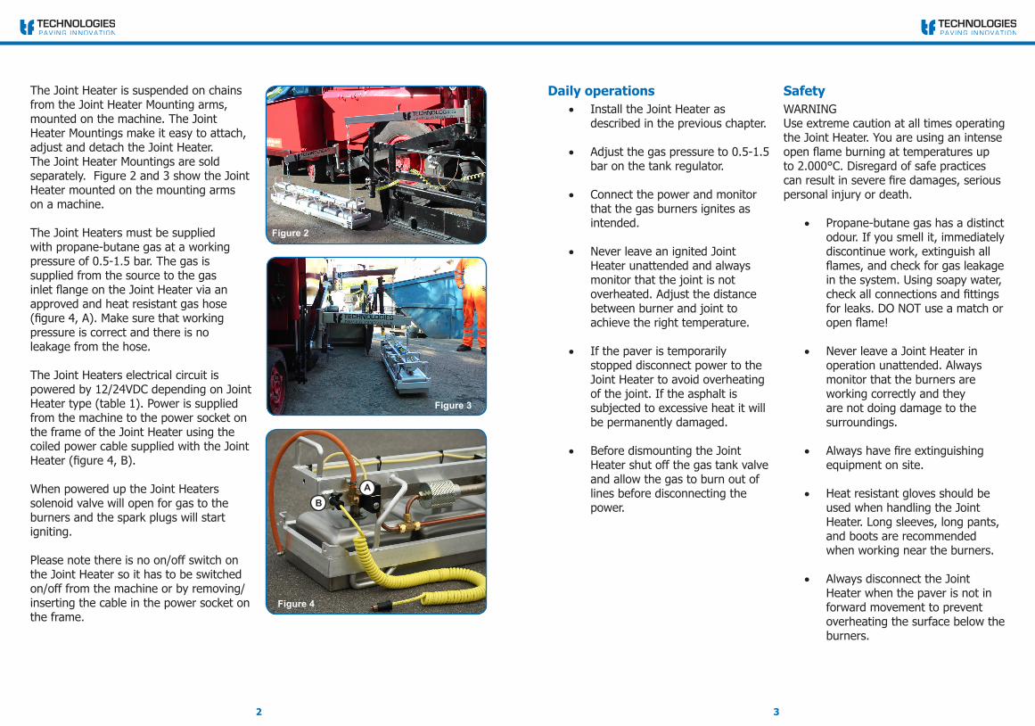
The Joint Heater is suspended on chains from the Joint Heater Mounting arms, mounted on the machine. The Joint Heater Mountings make it easy to attach, adjust and detach the Joint Heater. The Joint Heater Mountings are sold separately. Figure 2 and 3 show the Joint Heater mounted on the mounting arms on a machine.
The Joint Heaters must be supplied with propane-butane gas at a working pressure of 0.5-1.5 bar. The gas is supplied from the source to the gas inlet flange on the Joint Heater via an approved and heat resistant gas hose (figure 4, A). Make sure that working pressure is correct and there is no leakage from the hose.
The Joint Heaters electrical circuit is powered by 12/24VDC depending on Joint Heater type (table 1). Power is supplied from the machine to the power socket on the frame of the Joint Heater using the coiled power cable supplied with the Joint Heater (figure 4, B).
When powered up the Joint Heaters solenoid valve will open for gas to the burners and the spark plugs will start igniting.
Please note there is no on/off switch on the Joint Heater so it has to be switched on/off from the machine or by removing/inserting the cable in the power socket on the frame.
Figure 3
Figure 4
AB
Figure 2
Figure 2

54
Power cable, 2x male c.
S-50420/4,0 X X X X X X
Igniton coil S-50520 X X X X X X
Ignition box TF-1B-24V S-50112 X X X
Ignition box TF-1B-12V S-50111 X X X
Spark plug cap S-50150 X X X X X X
Sparkplug, 100mm S-50009 X X X X X X
Solonoid valve 12v S-50016 X X X
Solonoid valve 24v S-50017/6 X X X
S-50
416
S-50
418
S-50
462
S-50
463
S-50
417
S-50
419
6 Burner Joint HeaterPowerlead and gashose included.200x30x40 cm (LxWxH), 30 kg
12V DC S-50416
24V DC S-50418
4 Burner Joint HeaterPowerlead and gashose included.120x30x40 cm (LxWxH), 19 kg
12V DC S-50462
24V DC S-50463
4 Burner ExtensionConnector kit included.120x30x40 cm (LxWxH), 19 kg
12V DC S-50417
24V DC S-50419
Table 1, Joint Heater types
Contents 1x 12V interconnecting cable1x Gas hose, 0.4m2x Quick release hose clamp2x PVC cable binder1x Hose flange2x M8x30 Cap Screw w. nut1x M8x70 Cap Screw
Table 2, Connector Kit includes:
Table 3, Spare parts
• Be certain to comply with all safety guidelines and local ordinances regarding the use of open flames.
Upgrading with a 4 burner extensionA 6-burner Joint Heater can be upgraded with a 4-burner extension and connector kit. The components of the connector kit are listed in table 2.
To upgrade follow these steps:
1. Locate the pipe stopper on the gaspipe opposite to the gas inlet on the main Joint Heater. Replace the stopper with the gas flange from the connector kit (figure 5, A). Make sure the connection is tight and without leakage.
2. Align the Joint Heater and the extension as shown on figure 5 and bolt them together with the M8x30/70 screws at the positions marked with white circles on the figure.
3. Connect the two gas flanges (figure 5, A and B) with the gas hose and tighten with the quick release hose clamps. Make sure the connection is tight and without leakage.
4. Connect the power cable to the two sockets on the Joint Heater and its extension and strip the cable to the gas hose (figure 5, C). Figure 5
A
C C
B