OPERATING INSTRUCTIONS - High Vac Depot · Table of contents. 1 About this manual 7 1.1 Validity 7...
72
OPERATING INSTRUCTIONS EN Translation of the Original TPG 361 ∣ TPG 362 Total pressure measuring and control unit
Transcript of OPERATING INSTRUCTIONS - High Vac Depot · Table of contents. 1 About this manual 7 1.1 Validity 7...

OPERATING INSTRUCTIONS EN
Translation of the Original
TPG 361 ∣ TPG 362Total pressure measuring and control unit

Dear Customer,Thank you for choosing a Pfeiffer Vacuum product. Your new total pressure measuring and control unit should support you in your individual application with full performance and without malfunctions. The name Pfeiffer Vacuum stands for high-quality vacuum technology, a comprehensive and complete range of top-quality products and first-class service. From this extensive, practical experience we have gained a large volume of information that can contribute to efficient deployment and to your personal safety.In the knowledge that our product must avoid consuming work output, we trust that our product can offer you a solution that supports you in the effective and trouble-free implementation of your individual application.Please read these operating instructions before putting your product into operation for the first time. If you have any questions or suggestions, please feel free to contact [email protected] operating instructions from Pfeiffer Vacuum can be found in the Download Center on our website.
Disclaimer of liabilityThese operating instructions describe all models and variants of your product. Note that your product may not be equipped with all features described in this document. Pfeiffer Vacuum constantly adapts its products to the latest state of the art without prior notice. Please take into account that online operating instructions can deviate from the printed operating instructions supplied with your product.Furthermore, Pfeiffer Vacuum assumes no responsibility or liability for damage resulting from the use of the product that contradicts its proper use or is explicitly defined as foreseeable misuse.
CopyrightThis document is the intellectual property of Pfeiffer Vacuum and all contents of this document are protected by copyright. They may not be copied, altered, reproduced or published without the prior written permission of Pfeiffer Vacuum.We reserve the right to make changes to the technical data and information in this document.
2/72

Table of contents
1 About this manual 71.1 Validity 7
1.1.1 Applicable documents 71.1.2 Variants 71.1.3 Firmware versions 7
1.2 Target group 71.3 Conventions 8
1.3.1 Instructions in the text 81.3.2 Pictographs 81.3.3 Product labels 81.3.4 Abbreviations 8
1.4 Trademarks 9
2 Safety 102.1 General safety instructions 102.2 Safety instructions 102.3 Safety precautions 142.4 Proper use 152.5 Foreseeable improper use 152.6 Responsibilities and warranty 152.7 Owner requirements 152.8 Personnel qualification 16
2.8.1 Ensuring personnel qualification 162.8.2 Personnel qualification for maintenance and repair 162.8.3 Advanced training with Pfeiffer Vacuum 17
2.9 Operator requirements 17
3 Transportation and storage 18
4 Product description 194.1 Identifying the product 194.2 Scope of delivery 194.3 Design, construction 194.4 Display elements 204.5 Controls 224.6 Interfaces 22
4.6.1 Mains power supply 224.6.2 Ground terminal 234.6.3 "sensor" connection 234.6.4 "control" connection 234.6.5 "relay" connection 244.6.6 Connection "RS-485" 254.6.7 "USB" connection (type B) 254.6.8 "USB" connection (type A) 254.6.9 "Ethernet" (LAN) connection 26
5 Installation 275.1 Installing the device in a 19” rack 275.2 Installing the device in a switchboard 285.3 Using the device as a desktop device 29
6 Commissioning 316.1 Switch on the device 316.2 Updating the firmware 316.3 Configuring Ethernet 33
7 Operation 36
Table of contents
3/72

7.1 Basic operation 367.2 Operating modes 367.3 Measuring mode 367.4 Parameter mode 38
7.4.1 Switching function parameters 407.4.2 Gauge parameters 417.4.3 Gauge control 437.4.4 General parameters 457.4.5 Test parameters 49
7.5 Data logger mode 517.6 Setup mode 53
8 Decommissioning 55
9 Maintenance 569.1 Cleaning the device 569.2 Replacing the battery 57
10 Errors 58
11 Shipping 59
12 Disposal 60
13 Service solutions from Pfeiffer Vacuum 61
14 Technical data and dimensions 6314.1 Technical data 6314.2 Dimensions 67
15 Appendix 6915.1 Units of pressure 6915.2 Gas throughputs 69
ETL Listed 70
Declaration of conformity 71
Table of contents
4/72

List of tablesTbl. 1: Applicable documents................................................................................................ 7Tbl. 2: Variants...................................................................................................................... 7Tbl. 3: Abbreviations used.....................................................................................................9Tbl. 4: Danger to life due to electric voltage........................................................................ 11Tbl. 5: Controls.................................................................................................................... 22Tbl. 6: Switching functions...................................................................................................24Tbl. 7: Switching functions...................................................................................................25Tbl. 8: Status of the Ethernet connection............................................................................ 26Tbl. 9: Description of the controls........................................................................................36Tbl. 10: Parameters in the "Switching function parameters" group....................................... 40Tbl. 11: Examples of switching function displays.................................................................. 40Tbl. 12: Upper and lower threshold values............................................................................41Tbl. 13: Parameters in the "Gauge parameters" group......................................................... 42Tbl. 14: Parameters available in the "Gauge parameters" group.......................................... 42Tbl. 15: Parameters in the "Gauge control" group.................................................................43Tbl. 16: Parameters available in the "Gauge control" group..................................................44Tbl. 17: Switch-on type (S-ON)..............................................................................................44Tbl. 18: Switch-off type (S-OFF)............................................................................................45Tbl. 19: Switch on/off thresholds........................................................................................... 45Tbl. 20: Parameters in the "General parameters" group....................................................... 45Tbl. 21: Parameters available in the "General parameters" group........................................ 46Tbl. 22: Parameters in the "Test parameters" group............................................................. 49Tbl. 23: Parameters in data logger mode.............................................................................. 52Tbl. 24: Parameters in setup mode....................................................................................... 53Tbl. 25: Errors........................................................................................................................58Tbl. 26: Technical data (general)...........................................................................................63Tbl. 27: Technical data (mains connection)...........................................................................63Tbl. 28: Technical data (ambient conditions).........................................................................63Tbl. 29: Technical data (gauge connections).........................................................................64Tbl. 30: Technical data (gauge supply)................................................................................. 64Tbl. 31: Technical data (operation)........................................................................................64Tbl. 32: Technical data (measured values)........................................................................... 64Tbl. 33: Technical data (switching functions).........................................................................65Tbl. 34: Technical data (switching function relay)..................................................................65Tbl. 35: Technical data (error signal (error))..........................................................................65Tbl. 36: Technical data (error signal relay)............................................................................65Tbl. 37: Technical data (gauge control).................................................................................66Tbl. 38: Technical data (analog outputs)............................................................................... 66Tbl. 39: Technical data (RS-485 interface)............................................................................66Tbl. 40: Technical data (USB interface (type A))...................................................................66Tbl. 41: Technical data (USB interface (type B))...................................................................67Tbl. 42: Technical data (Ethernet interface).......................................................................... 67Tbl. 43: Units of pressure and their conversion.....................................................................69Tbl. 44: Gas throughputs and their conversion......................................................................69
List of tables
5/72

List of figuresFig. 1: Disconnect device in accordance with EN 61010-1................................................. 11Fig. 2: Front panel............................................................................................................... 19Fig. 3: Connections on the rear side....................................................................................20Fig. 4: Display......................................................................................................................20Fig. 5: Parameter or bar graph............................................................................................ 21Fig. 6: Switch-points, parameter mode and input lock.........................................................21Fig. 7: Measurement channel status................................................................................... 22Fig. 8: Mains connection with IEC 320 C13 socket............................................................. 23Fig. 9: Gauge connection (6-pin Amphenol C 091 B socket).............................................. 23Fig. 10: "control" connection (7-pin Amphenol C 091 B socket)............................................24Fig. 11: "relay" connection (15-pole D-Sub socket)...............................................................24Fig. 12: "RS-485" connection (5-pole Binder M12 socket).................................................... 25Fig. 13: "USB" connection (type B)........................................................................................25Fig. 14: "USB" connection (type A)........................................................................................25Fig. 15: "Ethernet" (LAN) connection.....................................................................................26Fig. 16: Guide rails................................................................................................................ 27Fig. 17: Rack module adapter (3 height units).......................................................................27Fig. 18: Device installation.....................................................................................................28Fig. 19: Required control panel cut-out................................................................................. 29Fig. 20: Fastening the rubber feet and rubber strip............................................................... 30Fig. 21: USB Update Tool......................................................................................................32Fig. 22: Ethernet Configuration Tool......................................................................................34Fig. 23: Change measurement channel (only for TPG 362)..................................................37Fig. 24: Switching gauges on and off.................................................................................... 37Fig. 25: Measurement range................................................................................................. 37Fig. 26: Identifying the gauge................................................................................................ 38Fig. 27: Change from measuring mode to parameter mode..................................................38Fig. 28: Select parameter group............................................................................................38Fig. 29: Read/write parameter groups and parameters.........................................................39Fig. 30: Switching functions and threshold values.................................................................41Fig. 31: Measured value filter fast, normal and slow (from left to right).................................43Fig. 32: Load factory settings: Press the arrow keys simultaneously > 2 seconds............... 48Fig. 33: Program memory test...............................................................................................50Fig. 34: Parameter memory test............................................................................................50Fig. 35: Display test...............................................................................................................51Fig. 36: Test of relays in the device.......................................................................................51Fig. 37: Start/stop measured data recording......................................................................... 52Fig. 38: Delete files................................................................................................................53Fig. 39: Formatting the USB memory stick............................................................................54Fig. 40: Delete parameter files from the USB memory stick..................................................54Fig. 41: Dimensions TPG 361 (in mm).................................................................................. 67Fig. 42: Dimensions TPG 362 (in mm).................................................................................. 68
List of figures
6/72

1 About this manualIMPORTANTRead carefully before use.Keep the manual for future consultation.
1.1 ValidityThis document describes the function of the products listed in the following and provides the most im-portant information for safe use. The description is written in accordance with the valid directives. The information in this document refers to the current development status of the products. The document retains its validity assuming that the customer does not make any changes to the product.
1.1.1 Applicable documents
Designation Document
“Measuring and control unit” communication instructionsTPG 361 | TPG 362
BG 5510
“Gauges” operating instructionsActiveLine gauge
(depending on the gauge used)
Declaration of conformity (Part of this document)
Tbl. 1: Applicable documents
1.1.2 VariantsThis document applies to products with the following part numbers:
Part number Designation
PT G28 040 TPG 361 SingleGauge
PT G28 290 TPG 362 DualGauge
Tbl. 2: Variants
The part number is found on the rating plate of the product.Pfeiffer Vacuum reserves the right to make technical changes without prior notification.The figures in this document are not to scale (Dimensions in mm).
1.1.3 Firmware versionsThis document is based on firmware version V010500.Older firmware versions do not have the full functionality described in this operating manual.Checking the firmware version
1. If the device is not functioning as it did before, check whether the correct firmware version is in-stalled.
2. If you have any questions about the firmware, contact Pfeiffer Vacuum.
1.2 Target groupThis operating instructions are aimed at all persons performing the following activities on the product:
● transport,● setup (installation),● usage and operation,● decommissioning,
About this manual
7/72

● maintenance and cleaning,● storage or disposal.
The work described in this document is only permitted to be performed by persons with the appropriate technical qualifications (expert personnel) or who have received the relevant training from Pfeiffer Vac-uum.
1.3 Conventions
1.3.1 Instructions in the textUsage instructions in the document follow a general structure that is complete in itself. The required ac-tion is indicated by an individual step or multi-part action steps.Individual action stepA horizontal, solid triangle indicates the only step in an action.
► This is an individual action step.Sequence of multi-part action stepsThe numerical list indicates an action with multiple necessary steps.
1. Step 12. Step 23. ...
1.3.2 PictographsPictographs used in the document indicate useful information.
Note
Tip
1.3.3 Product labelsThis section describes all the labels on the product along with their meaning.
S/N
Made in Romania 2018/05
44990000
Mod.
P/N
Input 100-240 V~ 50-60 Hz 65 W
PT G28 290TPG 362
D-35614 Asslar
4010094
Rating plateThe rating plate is located on the right-hand side of the device.
1.3.4 Abbreviations
Abbreviation Explanation
A/D Analog/Digital
F.S. Full Scale (limit value)
FSR Full Scale Range (upper range value)
About this manual
8/72

Abbreviation Explanation
SP Switch-point (setpoint)
UART Universal Asynchronous Receiver Transmitter
Tbl. 3: Abbreviations used
1.4 Trademarks● FullRange® is a trademark of Pfeiffer Vacuum GmbH.
About this manual
9/72

2 Safety
2.1 General safety instructionsThis document includes the following four risk levels and one information level.
DANGERImminent dangerIndicates a hazardous situation which, if not avoided, will result in death or serious injury.► Instructions on avoiding the hazardous situation
WARNINGPossibly imminent dangerIndicates a hazardous situation which, if not avoided, could result in death or serious injury.► Instructions on avoiding the hazardous situation
CAUTIONPossibly imminent dangerIndicates a hazardous situation which, if not avoided, could result in minor or moderate injury.► Instructions on avoiding the hazardous situation
NOTICEDanger of property damageNotice is used to address practices not related to physical injury.► Instructions on avoiding property damage
Notes, tips or examples indicate important information on the product or on this document.
2.2 Safety instructionsSafety instructions according to product’s life stagesAll safety instructions in this document are based on the results of a risk assess-ment. Pfeiffer Vacuum has taken into account all the relevant life stages of the product.
Safety
10/72

Danger to life due to electric voltage
DANGERDanger to life due to electric voltageHigh voltages are present inside the device. When touching parts that are live, there is a risk of death. If there is visible damage, there is a risk of death when commissioning the device.► Work on the open device must only be carried out by trained specialist personnel.► Before carrying out any installation and maintenance work, switch the device off and disconnect
it from the current supply.– After switching off, wait about 60 seconds and then disconnect all cables (power cable at
the end).► Never open the device with the current supply connected.► Secure the current supply against unauthorized or unintentional reactivation.► Do not insert any objects into the vent openings.► Never open an external power supply unit.► Never operate an open or defective device.► Secure a defective device against accidental operation.► Protect the device against moisture.
Do not insert any objects into the vent openings.
Protect the device against moisture.
Tbl. 4: Danger to life due to electric voltage
Disconnect device
1
Fig. 1: Disconnect device in accordance with EN 61010-1
1 Disconnect device
The disconnect device must be clearly recognizable by the user and within easy reach.
Safety
11/72

Risks during transport
NOTICEDamage caused by incorrect transportationTransportation in unsuitable packaging, or failure to install all transport locks, can damage the prod-uct.► Comply with the instructions for safe transportation.
Risks during storage
NOTICEDamage caused by improper storageImproper storage will lead to damage to the product.Static charging, moisture, etc. lead to defects on the electronic components.► Comply with the instructions for safe storage.
Risks during installation
DANGERDanger to life from electric shockThe internal earthed conductor is fastened to the housing by a screw. A device without an earthed conductor attached can be life-threatening in the event of a malfunction.► Do not rotate or loosen the screw on the internal earthed conductor.
DANGERDanger to life due to dangerous contact voltageVoltages above 30 V (AC) or 60 V (DC) are considered dangerous in accordance with EN 61010. If you come into contact with dangerous contact voltage, this can result in injury through electric shocks or even death.► Only apply protected extra-low voltage (PELV).
DANGERRisk to life due to electric shockAn improperly earthed unit is a potential threat to life in the event of a fault.► Conduct the electrical connection in accordance with locally applicable regulations.► Make sure that the local mains voltage and frequency match rating plate specifications.► Use only a 3-pin mains cable and extension cables with properly connected protective earthing
(earthed conductor).► Plug the mains plug into a socket with earthing contact only.
– Protection must not be impaired by an extension with no earthed conductor.► Always connect the mains cable prior to all other cables, to ensure continuous protective earth-
ing.– In reverse: always disconnect all other cables prior to disconnecting the mains cable.
NOTICELoss of control cabinet protection classAs a built-in unit, the device can negate the required protection class (protection against foreign mat-ter and water) of control cabinets according to EN 60204-1, for example.► Take suitable measures to reestablish the required protection class.
Safety
12/72

NOTICEDamage caused by penetrating moisturePenetrating moisture, e.g. through condensation or dripping water, damages the device.► Protect the device against moisture penetrating.► Only operate the device in a clean and dry environment.► Operate the device away from fluids and humidity sources.► Take special precautions if there is a risk of dripping water.► Do not switch on the device if fluid has penetrated into it, instead contact the Pfeiffer Vacuum
Service Center.
NOTICEDamage caused by overheatingThe ambient temperature must not exceed the permissible operating temperature of the device.► Make sure there is unobstructed circulation of air when installing the device.► Make sure that air can enter and exit through the ventilation openings without obstruction.► Do not cover the ventilation openings.► Periodically check and clean the installed air filter.
Risks during operation
DANGERElectric shocks due to moisture penetrating into the deviceWater that has penetrated into the device results in personal injury through electric shocks.► Only operate the device in a dry environment.► Operate the device away from fluids and humidity sources.► Do not switch on the device if fluid has penetrated into it, instead contact Pfeiffer Vacuum Serv-
ice.► Always disconnect the current supply before cleaning the device.
NOTICEUnintentional results with controller connectedSwitch relay not dependent on pressure. Values below the intended measuring range, or starting the test program, can result in unintentional results at the connected controller, if the relay switches.► Unplug the connected measuring and control cable.► Prevent triggering of incorrect control commands or messages.
Risks during maintenance
DANGERDanger to life due to electric voltageHigh voltages are present inside the device. When touching parts that are live, there is a risk of death. If there is visible damage, there is a risk of death when commissioning the device.► Work on the open device must only be carried out by trained specialist personnel.► Before carrying out any installation and maintenance work, switch the device off and disconnect
it from the current supply.– After switching off, wait about 60 seconds and then disconnect all cables (power cable at
the end).► Never open the device with the current supply connected.► Secure the current supply against unauthorized or unintentional reactivation.► Do not insert any objects into the vent openings.► Never open an external power supply unit.► Never operate an open or defective device.► Secure a defective device against accidental operation.► Protect the device against moisture.
Safety
13/72

WARNINGHealth hazard through poisoning from toxic contaminated components or devicesToxic process media result in contamination of devices or parts of them. During maintenance work, there is a risk to health from contact with these poisonous substances. Illegal disposal of toxic sub-stances causes environmental damage.► Take suitable safety precautions and prevent health hazards or environmental pollution by toxic
process media.► Decontaminate affected parts before carrying out maintenance work.► Wear protective equipment.
WARNINGHealth hazards due to cleaning agentThe cleaning agents used cause health hazards.► When handling cleaning agents, observe the applicable regulations.► Adhere to safety measures regarding handling and disposal of cleaning agents.► Be aware of potential reactions with product materials.
NOTICEDamage caused by unsuitable cleaning agentsUnsuitable cleaning agents damage the product.► Do not use solvents as they attack the surface.► Do not use any aggressive or abrasive cleaning agents.
Risks when shipping
WARNINGRisk of poisoning from contaminated productsWhere products that contain harmful substances are shipped for maintenance or repair purposes, the safety of service personnel is at risk.► Comply with the instructions for safe shipping.
Risks during disposal
CAUTIONHealth hazard caused by environmentally hazardous substancesProducts, operating fluid, electric components, calibration gas residues (for example from test leaks) or similar pose health hazards.► Dispose of the environmentally hazardous substances in accordance with local regulations.► Dispose of calibration gas and test leaks in accordance with local regulations.
2.3 Safety precautionsThe product is designed according to the latest technology and recognized safety engineering rules. Nevertheless, improper use can result in danger to operator all third party life and limb, and product damage and additional property damage.
Duty to provide information on potential dangersThe product holder or user is obliged to make all operating personnel aware of dan-gers posed by this product.Every person who is involved in the installation, operation or maintenance of the product must read, understand, and adhere to the safety-related parts of this docu-ment.
Safety
14/72

Infringement of conformity due to modifications to the productThe Declaration of Conformity from the manufacturer is no longer valid if the opera-tor changes the original product or installs additional equipment.
● Following installation into a system, the operator is required to check and re-evaluate as necessary the conformity of the overall system in the context of the relevant european Directives before commissioning that system.
Meet fundamental safety measures1. When handling the gases and contaminated parts used, observe the applicable guidelines.2. Observe the protective measures.3. Observe the safety guidelines specified in this document.
– All work is only permissible when observing the relevant guidelines and adhering to the pro-tective measures.
4. Inform yourself about any contamination before starting work.5. Pass on safety instructions to all other users.
2.4 Proper useThe total pressure measuring gauge and control unit are used together with the Pfeiffer Vacuum Active-Line gauges to measure total pressures. Typical applications are measurement, monitoring and process control tasks in vacuum systems.Using the product according to its intended purpose
1. Install, operate and maintain the product only in accordance with these operating instructions.2. Comply with the application limits.3. Observe the technical data.
2.5 Foreseeable improper useImproper use of the product invalidates all warranty and liability claims. Improper use is any, even unin-tended, use, which is contrary to the product purpose; and in particular:
● Use outside the mechanical and electrical application limits (technical data)● Use with corrosive or explosive media, if this is not explicitly permitted● Use outdoors● Use after technical changes (inside or outside on the product)● Use with replacement or accessory parts that are inadequate or are not approved
2.6 Responsibilities and warrantyPfeiffer Vacuum shall assume no responsibilities and warranty if the operating company or a third par-ty::
● disregards this document.● does not use the product for its intended purpose.● carries out any modifications to the product (conversions, changes, maintenance work, etc.) that
are not listed in the corresponding product documentation.● operates the product with accessories that are not listed in the corresponding product documenta-
tion.The operator is responsible for the process media used.
2.7 Owner requirementsSafety-conscious working
1. Only operate the product in a technically flawless state.2. Operate the product in line with its intended purpose, safety and hazard-conscious as well as
when observing the operating instructions.3. Fulfill the following guidelines and monitor their observation:
– Proper use– Generally applicable safety instructions and accident prevention regulations– International, national and locally applicable standards and guidelines
Safety
15/72

– Additional product-related guidelines and regulations4. Only use original parts or parts approved by Pfeiffer Vacuum.5. Keep the operating instructions available at the place of installation.6. Ensure personnel qualification.
2.8 Personnel qualificationThe work described in this document may only be carried out by persons who have appropriate profes-sional qualifications and the necessary experience or who have completed the necessary training as provided by Pfeiffer Vacuum.Training people
1. Train the technical personnel on the product.2. Only let personnel to be trained work with and on the product when under the supervision of
trained personnel.3. Only allow trained technical personnel to work with the product.4. Before starting work, make sure that the commissioned personnel have read and understood
these operating instructions and all applicable documents, in particular the safety, maintenance and repair information.
2.8.1 Ensuring personnel qualificationSpecialist for mechanical workOnly a trained specialist may carry out mechanical work. Within the meaning of this document, special-ists are people responsible for construction, mechanical installation, troubleshooting, and maintenance of the product, and who have the following qualifications:
● Qualification in the mechanical field in accordance with nationally applicable regulations● Knowledge of this documentation
Specialist for electrical engineering workOnly a trained electrician may carry out electrical engineering work. Within the meaning of this docu-ment, electricians are people responsible for electrical installation, commissioning, troubleshooting, and maintenance of the product, and who have the following qualifications:
● Qualification in the electrical engineering field in accordance with nationally applicable regulations● Knowledge of this documentation
In addition, these individuals must be familiar with applicable safety regulations and laws, as well as the other standards, guidelines, and laws referred to in this documentation. The above individuals must have expressly granted operational authorization, to commission, program, configure, mark, and earth devices, systems, and circuits in accordance with safety technology standards.Trained individualsOnly adequately trained individuals may carry out all works in other transport, storage, operation, and disposal fields. Such training must ensure that individuals are capable of carrying out the required activi-ties and work steps safely and properly.
2.8.2 Personnel qualification for maintenance and repair
Advanced training coursesPfeiffer Vacuum offered advanced training courses to maintenance levels II and III.
Adequately trained individuals are:● Maintenance level I
─ Customer (trained specialist)● Maintenance level II
─ Customer with technical education─ Pfeiffer Vacuum service technician
● Maintenance level III─ Customer with Pfeiffer Vacuum service training─ Pfeiffer Vacuum service technician
Safety
16/72

2.8.3 Advanced training with Pfeiffer VacuumFor optimal and trouble-free use of this product, Pfeiffer Vacuum offers a comprehensive range of courses and technical training.For more information, please contact Pfeiffer Vacuum technical training.
2.9 Operator requirementsObserving relevant documents and data
1. Read, observe and follow this operating instructions and the work instructions prepared by the op-erating company, in particular the safety and warning instructions.
2. Install, operate and maintain the product only in accordance with these operating instructions.3. Carry out all work only on the basis of the complete operating instructions and applicable docu-
ments.4. Comply with the application limits.5. Observe the technical data.6. Please contact the Pfeiffer Vacuum Service Center if your questions on operation or maintenance
of the product are not answered by this operating manual.– You can find information in the Pfeiffer Vacuum service area.
Safety
17/72

3 Transportation and storageNOTICE
Damage caused by incorrect transportationTransportation in unsuitable packaging, or failure to install all transport locks, can damage the prod-uct.► Comply with the instructions for safe transportation.
NOTICEDamage caused by improper storageImproper storage will lead to damage to the product.Static charging, moisture, etc. lead to defects on the electronic components.► Comply with the instructions for safe storage.
Instructions for safe transportation1. Observe the weight of the product (see technical data).2. Where possible, always transport or ship the product in the original packaging.3. Always use dense and impact-proof packaging for the product.4. Only remove the present protective cover immediately prior to installation.5. Reattach transport locks prior to every transport.
Instructions for safe storage1. Store the product in a cool, dry, dust-free place, where it is protected against impacts and me-
chanical vibration.2. Always use dense and impact-proof packaging for the product.3. Where possible, store the product in the original packaging.4. Store electronic components in antistatic packaging.5. Maintain the permissible storage temperature.6. Avoid extreme fluctuations of the ambient temperature.7. Avoid high air humidity.8. Seal connections with the original protective caps.9. Protect the product with the original transport protections (where available).
Transportation and storage
18/72

4 Product description
4.1 Identifying the productYou will need all the data from the rating plate to safely identify the product when communicating with Pfeiffer Vacuum.Recording rating plate data
1. Read the data on the product rating plate.2. Record this data.3. Always have all rating plate specifications to hand.
4.2 Scope of deliveryThe shipment includes the following parts:
● 1 × total pressure measuring and control unit● 1 × mains cable● 1 × cable connector for the "control" connection● 4 × collar screws with synthetic nipple● 2 × rubber feet● 1 × rubber strip● 1 × installation instructions● 1 × operating instructions
Unpacking the product and checking completeness of the shipment1. Unpack the product.2. Remove transport seals, transport locks, etc. and store them.3. Check that the shipment is complete.4. Ensure that no parts are damaged.
4.3 Design, construction
DANGERDanger to life from electric shockThe internal earthed conductor is fastened to the housing by a screw. A device without an earthed conductor attached can be life-threatening in the event of a malfunction.► Do not rotate or loosen the screw on the internal earthed conductor.
1
2
3
Fig. 2: Front panel
1 Display 3 USB connection (type A)
2 Controls
Product description
19/72

10
9
8
7
11
3
2
6
5
1
4
Fig. 3: Connections on the rear side
1 Ethernet interface 7 "sensor 2" connection for gauges (only for TPG 362)
2 USB connection (type B) 8 "sensor" connection for gauges (only for TPG 362: "sen-sor 1")
3 Protective earth 9 "control" connection for control functions
4 "relay" connection with relay con-tacts
10 "RS 485" connection as a serial interface
5 Master switch 11 Internal earthed conductor
6 Mains power supply
4.4 Display elementsDisplay elements of the device
1
2
3
47
6
5
Fig. 4: Display
Product description
20/72

1 Parameter or bar graph 5 Unit of pressure or voltage
2 Switch-points, parameter mode and input lock
6 Measured value in floating point or exponential no-tation (measurement channel 1)
3 Measurement channel status (measurement channel 1)
7 Measured value in floating point or exponential no-tation (measurement channel 2) (only for TPG 362)
4 Measurement channel status (measurement channel 2) (only for TPG 362)
Parameter or bar graph
1
2
3
4
Fig. 5: Parameter or bar graph
1 Display for measurement channel 1 and 2 3 Bar graph with switch-point for measurement channel 1
2 Parameter display for measurement channel 1 4 Pressure vs. time, trend for measurement chan-nel 1
Switch-points, parameter mode and input lock
5 4
1 2 3
Fig. 6: Switch-points, parameter mode and input lock
1 Switch-points from relay 1 to 4 4 Relay 3 off
2 Parameter mode activated 5 Relay 1 on
3 Input lock activated
Measurement channel status
1
2
3
4
5
6
Product description
21/72

Fig. 7: Measurement channel status
1 Error 4 High vacuum sensor
2 Calibration factor (COR) 5 Measurement channel
3 Degas 6 Offset
4.5 Controls
Key Designation Functions (depending on operating mode)
Parameter ● Change to parameter mode● Select parameter/group● Confirm selection● Save changes and return to read mode
12
Measurement channel(Only for TPG 362)
Change measurement channel
UP and DOWN arrow keys
● Select parameter● Press for < 1 second: Increase/reduce/change value
by increments● Press for > 1 second: Increase/reduce/change value
continually
Tbl. 5: Controls
4.6 Interfaces
4.6.1 Mains power supply
DANGERRisk to life due to electric shockAn improperly earthed unit is a potential threat to life in the event of a fault.► Conduct the electrical connection in accordance with locally applicable regulations.► Make sure that the local mains voltage and frequency match rating plate specifications.► Use only a 3-pin mains cable and extension cables with properly connected protective earthing
(earthed conductor).► Plug the mains plug into a socket with earthing contact only.
– Protection must not be impaired by an extension with no earthed conductor.► Always connect the mains cable prior to all other cables, to ensure continuous protective earth-
ing.– In reverse: always disconnect all other cables prior to disconnecting the mains cable.
The mains connection with mains switch is located on the rear side of the device. A mains cable is in-cluded in the shipment. If the mains plug is not compatible with your system, you can use a separate, suitable mains cable with earthed conductor (3 × 1.5 mm2). If you install the device in a control cabinet, we recommend that you supply the mains voltage via a switched mains distributor. The socket re-quires a 10 A fusemax.
Product description
22/72
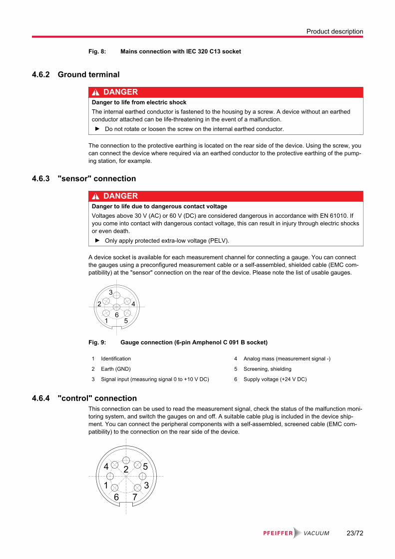
Fig. 8: Mains connection with IEC 320 C13 socket
4.6.2 Ground terminal
DANGERDanger to life from electric shockThe internal earthed conductor is fastened to the housing by a screw. A device without an earthed conductor attached can be life-threatening in the event of a malfunction.► Do not rotate or loosen the screw on the internal earthed conductor.
The connection to the protective earthing is located on the rear side of the device. Using the screw, you can connect the device where required via an earthed conductor to the protective earthing of the pump-ing station, for example.
4.6.3 "sensor" connection
DANGERDanger to life due to dangerous contact voltageVoltages above 30 V (AC) or 60 V (DC) are considered dangerous in accordance with EN 61010. If you come into contact with dangerous contact voltage, this can result in injury through electric shocks or even death.► Only apply protected extra-low voltage (PELV).
A device socket is available for each measurement channel for connecting a gauge. You can connect the gauges using a preconfigured measurement cable or a self-assembled, shielded cable (EMC com-patibility) at the "sensor" connection on the rear of the device. Please note the list of usable gauges.
4
5
3
2
16
Fig. 9: Gauge connection (6-pin Amphenol C 091 B socket)
1 Identification 4 Analog mass (measurement signal -)
2 Earth (GND) 5 Screening, shielding
3 Signal input (measuring signal 0 to +10 V DC) 6 Supply voltage (+24 V DC)
4.6.4 "control" connectionThis connection can be used to read the measurement signal, check the status of the malfunction moni-toring system, and switch the gauges on and off. A suitable cable plug is included in the device ship-ment. You can connect the peripheral components with a self-assembled, screened cable (EMC com-patibility) to the connection on the rear side of the device.
3
7
2
1
6
54
Product description
23/72

Fig. 10: "control" connection (7-pin Amphenol C 091 B socket)
1 Analog output gauge 2 0 to +10 V (DC) (only for TPG 362) 1) 5 Shielding GND
2 Analog output gauge 1 0 to +10 V (DC) 2) 6 Gauge 2 (only for TPG 362)
3, 7 Switching function (relay) 7 Switching function (relay)
4 Gauge 1
Pins Switching function Description Switching function Description
3 No errors Error or device switched off
7
4 on Signal ≤ +0.8 V DC
Off Signal +2.0 to 5 V (DC) or input open
6 on Signal ≤ +0.8 V DC
Off Signal +2.0 to 5 V (DC) or input open
Tbl. 6: Switching functions
4.6.5 "relay" connection
DANGERDanger to life due to dangerous contact voltageVoltages above 30 V (AC) or 60 V (DC) are considered dangerous in accordance with EN 61010. If you come into contact with dangerous contact voltage, this can result in injury through electric shocks or even death.► Only apply protected extra-low voltage (PELV).
You can use this connection to use the zero-potential (floating) state of the switching functions for exter-nal control. You can connect the peripheral components with a self-assembled, screened cable (EMC compatibility) to the connection on the rear side of the device.
18
915
→
→
Fig. 11: "relay" connection (15-pole D-Sub socket)
1, 8 Earth (GND) 3) 5, 6, 7 Switching function 2
15 +24 V (DC), 200 mA 4) 9, 10, 11 Switching function 3 (only for TPG 362)
2, 3, 4 Switching function 1 12, 13, 14 Switching function 4 (only for TPG 362)
1) If you have not connected a gauge to the respective measurement channel, the voltage at the analog output slowly rises to around 13.6 V.
2) If you have not connected a gauge to the respective measurement channel, the voltage at the analog output slowly rises to around 13.6 V.
3) Supply for relays with higher switching power. Fused at 200 mA with PTC element, self-resetting after switch-ing off the device or after unplugging the “relay” plug. Meets the requirements of protected extra-low voltage (PELV).
4) Supply for relays with higher switching power. Fused at 200 mA with PTC element, self-resetting after switch-ing off the device or after unplugging the “relay” plug. Meets the requirements of protected extra-low voltage (PELV).
Product description
24/72

Pins Switching function
Description Switching function
Description
4 7 11 14 Pressure lower than threshold val-ue
Pressure higher than threshold value or device switched off
3 6 10 13
2 5 9 12
Tbl. 7: Switching functions
4.6.6 Connection "RS-485"The "RS-485" connection enables control of the device using a computer or terminal. The use of a Y-distributor permits the integration into a bus system. You can connect the serial interface with a shielded cable (EMC compatibility) to the "RS-485" connection on the rear of the device.If a virtual series interface (COM) is not automatically set up, you can download the driver from FTDI Chip (Virtual COM Port Drivers) and then install it.
4
1
3
25
Fig. 12: "RS-485" connection (5-pole Binder M12 socket)
1 RS-485+ (differential) 4 RS-485+ (differential)
2 +24 V (DC), ≤ 200 mA 5 unassigned
3 Earth (GND)
4.6.7 "USB" connection (type B)The "USB" connection (type B) enables direct communication with the device via a computer (e.g. firm-ware updates, storing parameters (reading/writing)). You can connect the USB interface with a screened cable (EMC compatibility) to the connection on the rear side of the device.
1
4
2
3
Fig. 13: "USB" connection (type B)
1 VBUS (5 V) 3 D+
2 D- 4 Earth (GND)
4.6.8 "USB" connection (type A)The "USB" connection (type A) with master functionality is located on the front side and is used to con-nect a USB memory stick (e.g. firmware updates, storing parameters (reading/writing), data logger).
1 4
Fig. 14: "USB" connection (type A)
Product description
25/72

1 VBUS (5 V) 3 D+
2 D- 4 Earth (GND)
4.6.9 "Ethernet" (LAN) connectionThe "Ethernet" connection enables direct communication with the device via a computer.
RJ-45
green
1 8
yellow
Fig. 15: "Ethernet" (LAN) connection
1 Transmission data (TD+) 6 Reception data (RD-)
2 Transmission data (TD-) 4, 5, 7, 8 Not used
3 Reception data (RD+)
LED Status Meaning
Green (link) lights up Hardware connection exists
dark No hardware connection
Yellow (activity) lit up (flickering) Data transmission runs
dark no data transmission / no connection
Tbl. 8: Status of the Ethernet connection
Product description
26/72
5 Installation
5.1 Installing the device in a 19” rack
NOTICEDamage caused by overheatingThe ambient temperature must not exceed the permissible operating temperature of the device.► Make sure there is unobstructed circulation of air when installing the device.► Make sure that air can enter and exit through the ventilation openings without obstruction.► Do not cover the ventilation openings.► Periodically check and clean the installed air filter.
NOTICELoss of control cabinet protection classAs a built-in unit, the device can negate the required protection class (protection against foreign mat-ter and water) of control cabinets according to EN 60204-1, for example.► Take suitable measures to reestablish the required protection class.
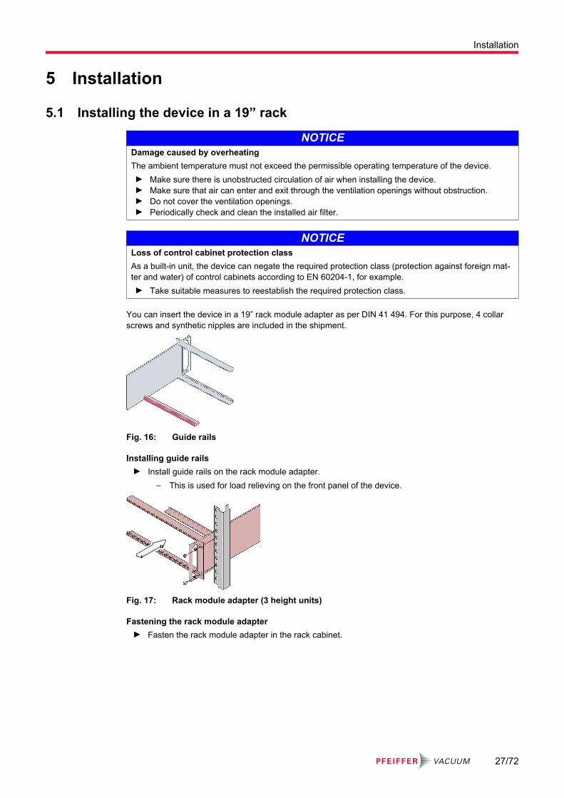
You can insert the device in a 19” rack module adapter as per DIN 41 494. For this purpose, 4 collar screws and synthetic nipples are included in the shipment.
Fig. 16: Guide rails
Installing guide rails► Install guide rails on the rack module adapter.
– This is used for load relieving on the front panel of the device.
Fig. 17: Rack module adapter (3 height units)
Fastening the rack module adapter► Fasten the rack module adapter in the rack cabinet.
Installation
27/72

Fig. 18: Device installation
Installing the device in the rack module adapterRequired tools
● ScrewdriverRequired material
● 4 × collar screws and synthetic nipple● Slide rails (optional)1. Recommendation: Install the slide rails in the rack frame for safe and easy installation of heavy
rack module adapters.2. Push the device into the rack module adapter.3. Fasten the device using the screws included in the shipment.
5.2 Installing the device in a switchboard
NOTICEDamage caused by overheatingThe ambient temperature must not exceed the permissible operating temperature of the device.► Make sure there is unobstructed circulation of air when installing the device.► Make sure that air can enter and exit through the ventilation openings without obstruction.► Do not cover the ventilation openings.► Periodically check and clean the installed air filter.
NOTICELoss of control cabinet protection classAs a built-in unit, the device can negate the required protection class (protection against foreign mat-ter and water) of control cabinets according to EN 60204-1, for example.► Take suitable measures to reestablish the required protection class.
Installation
28/72

M3 or Ø3.5
12
2.5
11
3
70
55.9
Fig. 19: Required control panel cut-out
Installing the device in a switchboardRequired tools
● ScrewdriverRequired material
● 4 screws (M3 or equivalent)1. Support the device from below to relieve the front panel.2. Push the device into the control panel cut-out.3. Support the device to relieve the front panel.4. Fasten the device using 4 screws.
5.3 Using the device as a desktop device
NOTICEDamage caused by overheatingThe ambient temperature must not exceed the permissible operating temperature of the device.► Make sure there is unobstructed circulation of air when installing the device.► Make sure that air can enter and exit through the ventilation openings without obstruction.► Do not cover the ventilation openings.► Periodically check and clean the installed air filter.
Installation
29/72

Fig. 20: Fastening the rubber feet and rubber strip
Using the device as a desktop deviceYou can use the device as a desktop device. The shipment includes two self-adhesive rubber feet as well as an attachable rubber strip, for this purpose.Required material
● 2 self-adhesive rubber feet● 1 attachable rubber strip1. Stick the 2 rubber feet at the rear side on the housing base.2. Stick the rubber strip on the front panel from underneath.
Installation
30/72

6 Commissioning
6.1 Switch on the devicePrerequisites
● You have installed the device correctly.● You have adhered to the technical data.► Switch on the device at the mains switch.► For rack assembly: Switch on the device centrally via the switched mains distributor.
After switching on:● The device performs a self test.● The device identifies the connected gauges.● The device activates the parameters that were in place on last switching off.● The device switches to measuring mode.● The device adjusts the parameters if necessary, if another gauge was connected previously.
6.2 Updating the firmwareIf your device requires a more recent firmware version, in order to support new gauges for example, please contact your nearest Pfeiffer Vacuum Service Center.A firmware update can be performed
● using a USB memory stick (USB type A on the front side of the device) or● using the USB Update Tool via the USB type B connection on the rear side of the device.
USB memory sticksThe device does not recognize all USB memory sticks, for instance if they do not comply with the USB standard. Try using a different memory stick first before you contact your nearest Pfeiffer Vacuum Service Center.
The settings you changed in parameter mode are usually also available after performing a firmware up-date. However, we recommend that you store the parameters before performing an update (set-up mode).Updating via a USB memory stick is an automatic process with the following steps:
1. BOOTING─ very short
2. BOOTLOADER V1.x─ very short
3. ERASING FW...─ Old firmware is deleted from the device.
4. UPDATING FW...─ New firmware is written to the device.
5. UPDATE COMPLETE─ Update is done.
Updating the firmware with a USB memory stick (USB type A)1. Open the Pfeiffer Vacuum Download Center in the browser.2. Enter the name of your device as the keyword.3. Select “Software”.
– The display lists the available documents and software.4. Download the ZIP file in the desired language.
– The ZIP file contains the files with file extension ".S19" and ".CNF".5. Unzip both files.6. Save both files on the USB memory stick.7. Turn off the device.8. Plug the USB memory stick into the device.9. Turn on the device.
Commissioning
31/72

– The update takes place automatically.10. Remove the USB memory stick from the device.
– The device automatically restarts.11. If required, write the customer-specific settings that were stored before the update back to the de-
vice.
Fig. 21: USB Update Tool
Updating the firmware with the USB Update Tool (USB type B)If a virtual series interface (COM) is not automatically set up, you can download the driver from FTDI Chip (Virtual COM Port Drivers) and then install it.Prerequisites
● You must use the Windows XP, 7, 8 or 10 operating system.● Make sure there is no USB memory stick connected to the front side of the device.1. Open the Pfeiffer Vacuum Download Center in the browser.2. Enter "USB Update Tool" as the keyword.
– The display lists the available software.3. Download the file in the desired language.4. Connect the device to the PC using a USB cable (type A/B).5. Start the USB Update Tool.6. Select the COM interface from the selection list.7. Click on "Connect".
Commissioning
32/72

8. Go to the "Release Notes" tab.– You will find the change log here.
9. Go to the "Manage Parameters" tab.– We recommend that you store the parameters here before performing an update.
10. Go to the "Manage Firmware" tab.11. Select the firmware.
– <Load from disk> (local file) or <Load from server> (server connection).12. Click on "Update".
– After the update, the status message "Firmware successfully updated!" appears at the bottom edge of the window.
13. If the update was not successful, repeat the procedure.14. Go to the "Manage Parameters" tab.15. Write the parameters back to the device.
6.3 Configuring EthernetThe Ethernet Configuration Tool enables the configuration of the Ethernet interface using a PC. Addi-tionally, you can assign a virtual series interface (COM) to an IP address. You an access the virtual COM interfaces using every program that supports series interfaces (e.g. terminal program, LabView, etc.). Depending on the protocol setting, communication with the device is either via the Mnemonic or Pfeiffer Vacuum protocol.
Commissioning
33/72

Fig. 22: Ethernet Configuration Tool
Ethernet Configuration Tool● The "Device Info" tab displays basic information about the selected device.● The automatic or manual network setting is made in the "Network Settings" tab.● In the "Virtual Serial Port" tab, you can assign a separate COM port to each device and/or gener-
ate a new COM port.
Commissioning
34/72
Using the Ethernet Configuration ToolPrerequisite
● You must use the Windows 7, 8 or 10 operating system.1. Recommendation: Contact your network administrator before you start the configuration.2. Recommendation: Update the operating system before you start the Ethernet configuration. You
also require administrator rights.3. Open the Pfeiffer Vacuum Download Center in the browser.4. Enter "Ethernet Configuration Tool" as the keyword.
– The display lists the available software.5. Download the file in the desired language.6. Connect the device to the network using an Ethernet cable.7. Start the Ethernet Configuration Tool.8. Click on "Search Devices".
– The tool searches for connected devices on the local network and lists the devices it finds in the selection window.
9. Make the required settings in the program.
Commissioning
35/72

7 Operation
7.1 Basic operationThe following section provides information about the most important basic operations for the individual modes.
Operation Description
1x
Press button
> 1s
1x
Press button for longer than one second
1x
Do not press button
1x
Press buttons simultaneously
Tbl. 9: Description of the controls
7.2 Operating modesThe device operates in the following modes:
● Measuring mode─ Display of measured value or status
● Parameter mode─ Display and input of parameters:─ Switching function parameter (SWITCH-POINT)─ Gauge parameter (SENSOR)─ Gauge control (SENSOR CONTROL)─ General parameters (GENERAL)─ Test program (TEST)
● Data logger mode─ Recording of measured data (DATA LOGGER)
● Setup mode─ Saving (reading/writing) parameters (SETUP)
7.3 Measuring modeMeasuring mode is the standard operations mode for the device:
● Displaying a bar graph (where required)
Operation
36/72

(see chapter “General parameters”, page 45)● Displaying a measured value per measurement channel● Displaying status messages per measurement channel
1x
Fig. 23: Change measurement channel (only for TPG 362)
Change measurement channelYou can use the "Measurement channel" button to switch between measurement channels. The num-ber of the selected measurement channel lights up.
► Press the "Measurement channel" button until the number of the desired measurement channel is displayed.
1x
1x
> 1s> 1s
Fig. 24: Switching gauges on and off
Switching gauges on and offYou can switch IKR, PKR, (MPT 200 AR), IMR and PBR (HPT 200 AR) gauges on and off manually, provided that you have set the gauge control to "S-ON | HAND".Instead of a measured value, a status message may be returned after switching OFF and switching on.
1. Press the “UP” arrow key for longer than 1 second in order to switch on the gauge.2. Press the “DOWN” arrow key for longer than 1 second in order to switch off the gauge.
Measurement range
Me
asu
rem
en
t
ran
ge
Pre
ssu
re p
Fig. 25: Measurement range
During operation with linear gauges (CTR, CCR), negative pressure values can be displayed.Possible causes are:
● Negative drift● Activated offset correction
Operation
37/72

> 1s
1x
Fig. 26: Identifying the gauge
Identifying the gauge► Hold down both arrow keys for longer than 1 second.
The device reads the gauge identification for the current measurement channel and displays this for 4 seconds, for example:
● PKR gauge connected: PKR● No gauge connected: NO SENSOR● Gauge connected but not identifiable: NO IDENT.
If you press the "Measurement channel" button during these 4 seconds, the gauge identification of the next measurement channel is also displayed for a further 4 seconds.
7.4 Parameter modeParameter mode is the operations mode for displaying and changing/entering parameter values, testing the device and saving measured data. Parameter groups exist for better structuring.
1x
Fig. 27: Change from measuring mode to parameter mode
Parameter groups● Switching function parameters● Gauge parameters● Gauge control● General parameters● Test parameters
1x
1x
1x
Fig. 28: Select parameter group
Operation
38/72

Power on
Measurement mode
Me
asu
rem
en
t va
lue
ch
an
ne
l n
Me
asu
rem
en
t va
lue
ch
an
ne
l 1
Edit
parameter
Pa
ram
ete
r n
Parameter
group
Gro
up
1G
rou
p 2
Gro
up
n
<
Display
parameter
Pa
ram
ete
r 1
Pa
ram
ete
r 2
Pa
ram
ete
r n
<
>10 s
>10 s
Fig. 29: Read/write parameter groups and parameters
Change parameters1. Press the "Parameter" button to switch to parameter mode.
– The display shows the respective parameter group instead of the bar graph. The symbol for Parameter mode lights up.
2. Press the “UP” and “DOWN” arrow buttons to select a parameter group.3. Press the "Parameter" button to confirm the parameter group.4. Read the parameters of the selected parameter group using the “UP” and “DOWN” arrow buttons.5. Press the "Parameter" button to confirm the desired parameter.
– The value flashes and you can now change it.6. Use the “UP” and “DOWN” arrow buttons to change the value.7. Press the "Parameter" button to save the change.
– You then return to read mode.
Operation
39/72

7.4.1 Switching function parameters
Parameter Description
SPn-S Assignment of switch-point n to a measurement channel
SPn-L Switch-point n: Lower threshold value (setpoint LOW)
SPn-H Switch-point n: Upper threshold value (setpoint HIGH)
Tbl. 10: Parameters in the "Switching function parameters" group
The switching function parameters group includes displaying and editing/inputting threshold values and assigning switching functions to a measurement channel. The lower and upper threshold value of a switching function always belong to the same channel. The last assignment to be carried out applies for both threshold values.The TPG 361 has 2, and the TPG 362 has 4 switching functions, each with 2 adjustable threshold val-ues. The states of the switching functions are shown on the display and are available as zero-potential contacts at the "relay" connection.The lower threshold value (setpoint low) defines the pressure at which the switching function is switched on if the pressure drops. The upper switching function (setpoint high) defines the pressure at which the switching function is switched off if the pressure rises.
Setting the threshold valuesPfeiffer Vacuum recommends setting the upper threshold value 1/2 decade above the lower threshold value or the lower threshold value 1/2 decade below the upper threshold value.
Display Description
SP1-S 1 Switching function 1 is assigned to channel 1.
SP1-S 2 Switching function 1 is assigned to channel 2.
SP1-S OFF Switching function 1 is switched off (factory setting).
SP1-S ON Switching function 1 is switched on.
SP1-L 5.00-4 Limit of the lower threshold value (gauge-dependent).If the gauge type changes, the device automatically adjusts the threshold value if necessary.
SP1-H 1500 Limit of upper threshold value (gauge-dependent)If the gauge type changes, the device automatically adjusts the threshold value if necessary.
Tbl. 11: Examples of switching function displays
Operation
40/72

Gauge type Lower threshold value [hPa] Minimum hysteresis Upper threshold value [hPa]
TPR/PCR(PPT 200 AR / RPT 200 AR)
5 · 10-4 5) +10% lower threshold value 1500
IKR 2x1 1 · 10-9 1 · 10-2
IKR 36x
IKR 270 1 · 10-11
PKR(MPT 200 AR)
1 · 10-9 1000
IMR 1 · 10-6 1000
PBR(HPT 200 AR)
5 · 10-10 1000
CMR/APR(CPT 200 AR)
F.S. / 1000 +1% measuring range (F.S.) F.S.
Gas = nitrogen
Tbl. 12: Upper and lower threshold values
Minimum hysteresisThe minimum hysteresis between the upper and lower threshold value is a mini-mum of 10% of the lower threshold value (logarithmic gauges) or 1% of the set up-per range value (linear gauges). The upper threshold value is automatically updat-ed with minimum hysteresis if required. This prevents an unstable state.
Pre
ssu
re p
Sw
itch
ing
fun
ctio
n
On Off
Time t
Off
2
3
4
2
3
4
2
3
4
Dis
pla
y
Measurement value
Fig. 30: Switching functions and threshold values
7.4.2 Gauge parameters
Parameter Description
DEGAS Clean electrode system
FSR Measuring range of linear gauges
FILTER Measured value filter
5) 5 · 10-5 hPa with activated RNE-EXT
Operation
41/72

Parameter Description
OFFSET Offset correction
GAS Calibration factor for other gas types
COR Calibration factor
SPACES Display resolution
Tbl. 13: Parameters in the "Gauge parameters" group
The gauge parameters group includes displaying and editing/inputting gauge-related parameters.Some parameters are not available for all gauges and are thus not always displayed.
Gauge type TPR/PCR(PPT 200 AR / RPT 200 AR)
IKR PKR(MPT 200 AR)
IMR PBR(HPT 200 AR)
CMR/APR(CPT 200 AR)Parameter
DEGAS X
FSR X
FILTER X X X X X X
OFFSET X
GAS X 6) X X 7) X 8) X 9) 10)
COR X X X X X X
SPACES X X X X X X
Tbl. 14: Parameters available in the "Gauge parameters" group
DEGASDeposits on the electrode system of hot ionization gauges can result in an unstable measured value. Degas enables cleaning of the electrode system by heating the electron collection grid to approx. 700°C through electron bombardment for 180 seconds (can be switched off prematurely by pressing the "UP" arrow button). The "Degas" display is lit up during this time. In normal operation, degas is locked (OFF).FSRWith linear gauges, you must define their upper range value (Full Scale); the device detects this auto-matically for logarithmic gauges.FILTERThe measured value filter permits a better evaluation of measurement signals with fluctuation or inter-ference. The measured value filter does not affect the analog output.
● OFF─ No measured value filter
● RAPID─ The device responds rapidly to measured value fluctuations and thus responds to measured
value disturbances in an accordingly sensitive manner.● NORMAL (factory setting)
─ Setting with good ratio between speed of response and sensitivity of display and switching function with respect to measured value changes.
● SLOW─ The device does not respond to minor measured value fluctuations and thus responds more
slowly to measured value changes. Pfeiffer Vacuum recommends this setting for precise comparison measurements.
6) Effective as of a pressure < 1 hPa.7) Effective as of a pressure < 1 · 10-5 hPa.8) With restrictions9) With restrictions10) Effective as of a pressure < 1 · 10-2 hPa.
Operation
42/72

p
t
p
t
p
t
Fig. 31: Measured value filter fast, normal and slow (from left to right)
OFFSETDisplays the offset value in the current unit of measure and recalibrates to the current measured value. Offset correction is switched off as the factory setting and affects the measured value display. Offset correction does not affect the threshold value display of the switching functions and the analog outputs at the “control” connection.If offset correction is enabled, the display lights up and the stored offset value is subtracted from the current measured value. This enables relative measurements with regard to a reference pressure.
Resetting the zero point on the gaugesYou must switch off offset correction before you reset the zero point on the gauges.
GASThe calibration factor GAS permits
● the standardization of the measured value to the non-adjustable gas types nitrogen (N2), Argon (Ar), Hydrogen (H2), Helium (He), Neon (Ne), Krypton (Kr) and Xenon (Xe), or
● the manual input of the calibration factor for other gases (parameter COR).This parameter is not available for the Volt unit of measure.CORThe calibration factor COR is effective across the entire measuring range and permits the standardiza-tion of the measured value to other gas types by a factor of 0.10 to 10.00. A prerequisite is that the "GAS" parameter is set to "COR". The display lights up when COR is switched on.This parameter is not available for the Volt unit of measure.SPACESResolution of the displayed measured value (decimal places). The factory setting is AUTO, which means that the number of places depends on the connected gauge and the current pressure value.The display is in the pressure range p < 1.0 · 10 for PCR gauges-4 hPa and reduces the activated range expansion by one decimal place.
7.4.3 Gauge control
Parameter Description
S-ON Gauge switch-on type
S-OFF Gauge switch-off type
T-ON(Only for TPG 362)
Switch-on threshold value
T-OFF Switch-off threshold value
Tbl. 15: Parameters in the "Gauge control" group
The gauge control group includes displaying and editing/inputting parameters used to define how gauges are switched on and off. If only gauges without a control option connected, the group is not available.Some parameters are not available for all gauges and are thus not always displayed.
Operation
43/72

Gauge type TPR/PCR(PPT 200 AR / RPT 200 AR)
IKR PKR(MPT 200 AR)
IMR PBR(HPT 200 AR)
CMR/APR(CPT 200 AR)Parameter
S-ON X X 11) X X
S-OFF X X 12)13) X 14) X 15)
T-ON X X X
T-OFF X X X
Tbl. 16: Parameters available in the "Gauge control" group
S-ONYou can switch on certain gauges using different switch-on types.
Adjustment, setting Description
HAND You can manually switch on the gauges by pressing the “UP” arrow button.
EXTERNAL You can switch on the gauges via the corresponding control input at the "con-trol" connection.
HOT START The gauge switches on automatically when the device is switched on. This al-lows measuring to continue following a power failure.
S 1(Only for TPG 362)
The gauge on measurement channel 1 automatically switches the gauges on. 16)
S 2(Only for TPG 362)
The gauge on measurement channel 2 automatically switches the gauges on. 17)
Tbl. 17: Switch-on type (S-ON)
S-OFFYou can switch off certain gauges using different switch-off types.
Adjustment, setting Description
HAND You can manually switch off the gauge by pressing the “DOWN” arrow button.
EXTERNAL You can switch off the gauge via the corresponding control input at the "con-trol" connection.
SELF 18) Self-monitoring: The gauge switches off automatically in case of a pressure rise.
S 1(Only for TPG 362)
The gauge on measurement channel 1 automatically switches the gauges off. 19)
S 2(Only for TPG 362)
The gauge on measurement channel 2 automatically switches the gauges off. 20)
11) Except through gauges on a different channel12) Except through gauges on a different channel13) Except for self-monitoring14) Except for self-monitoring15) Except for self-monitoring16) Not for IKR gauges, CMR/APR gauges only with 1, 10 or 100 hPa F.S.17) Not for IKR gauges, CMR/APR gauges only with 1, 10 or 100 hPa F.S.18) Additionally for IKR gauges19) Not for IKR gauges, CMR/APR gauges only with 1, 10 or 100 hPa F.S.20) Not for IKR gauges, CMR/APR gauges only with 1, 10 or 100 hPa F.S.
Operation
44/72

Tbl. 18: Switch-off type (S-OFF)
T-ON (TPG 362)Definition of the switch-on threshold value when using the gauge on the other channel to switch on. The T-OFF value must be ≥ T-ON.T-OFF (TPG 361)Definition of the switch-off threshold with self-monitoring.Value = 10-5 – 10-2 hPa, GAS = N2
T-OFF (TPG 362)Definition of the switch-off threshold value when using the gauge on the other channel to switch off, or for self-monitoring. The T-OFF value must be ≥ T-ON.
Gauge type TPR/PCR(PPT 200 AR / RPT 200 AR)
PKR/IMR/PBR(MPT 200 AR / HPT 200 AR)
CMR/APR(CPT 200 AR)
F.S. = 1 F.S. = 10 F.S. = 100
IKR 10-3 Up to 10-2 21) 10-5 Up to 10-2 10-3 – 10-2 - -
IMR 10-3 Up to 1 22) 10-5 Up to 1 10-3 – 1 10-2 – 1 10-1 – 1
PBR(HPT 200 AR)
10-3 Up to 1 23) 10-5 Up to 1 10-3 – 1 10-2 – 1 10-1 – 1
all values in hPa, CAL = 1
Tbl. 19: Switch on/off thresholds
7.4.4 General parameters
Parameter Description
UNIT Unit of measure
BAUD USB Baud rate of the USB interface
RANGE EXT Pirani range extension
ERR. RELAY Error relay
PE-UR Penning underrange
BAR GRAPH Display in bar graph
ADDRESS RS-485 device address
PROTOCOL Serial interface protocol
BACKLIGHT Background lighting
SCREENSAVER Screensaver
CONTRAST Contrast setting
STANDARD Factory settings
LANGUAGE Language
FORMAT Number format of the measured value
END VALUE Representation of the upper range value
Tbl. 20: Parameters in the "General parameters" group
21) 10-4 hPa if range extension is enabled22) 10-4 hPa if range extension is enabled23) 10-4 hPa if range extension is enabled
Operation
45/72

The general parameters group includes displaying and editing/inputting generally-applicable parameters (system parameters).
Gauge type TPR/PCR(PPT 200 AR / RPT 200 AR)
IKR PKR(MPT 200 AR)
IMR PBR(HPT 200 AR)
CMR/APR(CPT 200 AR)Parameter
UNIT X X X X X X
BAUD USB X X X X X X
RANGE EXT X
ERR. RELAY X X X X X X
PE-UR X
BAR GRAPH X X X X X X
ADDRESS X X X X X X
PROTOCOL X X X X X X
BACKLIGHT X X X X X X
SCREENSAVER X X X X X X
CONTRAST X X X X X X
STANDARD X X X X X X
LANGUAGE X X X X X X
FORMAT X X X X X X
END VALUE X X X X X X
Tbl. 21: Parameters available in the "General parameters" group
UNITThe unit of measure for the measured values, threshold values etc.
● mbar● hPa (factory setting)● Torr (only available if the Torr lock is not activated.)● Pa● Micron (= 0.001 Torr) (only available if the Torr lock is not activated.)● Volt
For TPG 361: If Micron is selected as the unit of measure, it automatically switches to Torr when the level exceeds 99000 Microns. Below 90 Torr, it automatically switches back to the Micron unit of meas-ure.BAUD USBTransfer rate of the USB interface. The transmission rate of the RS-485 interface is 9600 baud; this cannot be changed.
● 9600 (factory setting), 19200, 38400, 57600 or 115200 baudRANGE EXTFor TPR and PCR gauges with display/measuring range up to 5 · 10-5 hPa, you can expand the display and switch-point setting area (only acts on the controller). This function is disabled as the factory set-ting.
● Display and switch-point setting range up to 5 · 10-5 hPaERR. RELAYThe switching behavior of the error relay.
● ALL─ Switches with all errors (factory setting)
● No SE─ Only device error
● S 1─ Error sensor 1 and device error
Operation
46/72

● S 2(Only for TPG 362)
─ Error sensor 2 and device errorPE-UR
NOTICEUnintentional results with controller connectedSwitch relay not dependent on pressure. Values below the intended measuring range, or starting the test program, can result in unintentional results at the connected controller, if the relay switches.► Unplug the connected measuring and control cable.► Prevent triggering of incorrect control commands or messages.
Definition of behavior if the value drops below the measuring range for cold cathode gauges (Penning underrange control).Various causes can lead to underrange values:
● The pressure in the vacuum system is below the measuring range.● The measuring element has (not) yet ignited.● Discharge has stopped.● A defect has occurred.● OFF
─ If the function is switched off (factory setting), an underrange measurement is interpreted as a permissible measured value. UR is displayed. The switching function remains ON.If the pressure in the vacuum system can drop below the measuring range of the gauge, se-lecting the "PE-UR OFF" option makes sense.
● ON─ If the function is switched off, an underrange measurement is interpreted as an impermissi-
ble measured value. UR is displayed. The switching function changes to OFF.For a setting of "PE-UR ON" the evaluation of the switching function is suppressed for 10 seconds after switching on the gauge and after returning from a measurement underrange case. The switching function remains OFF for this time.
BAR GRAPHA bar graph or the measured pressure as a function of time (p = f(t)) can be shown on the display. Dur-ing parameter setting, the parameter and the parameter value are displayed here.
● OFF─ Disabled (factory setting)
● FSR─ Bar graph over entire measuring range of gauge
● FSR h─ Bar graph over entire measuring range of gauge, high representation
● FSR+SP─ over entire measuring range of gauge and switch-point threshold value
● DEC─ Bar graph over one decade in accordance with current measured value
● DEC h─ Bar graph over one decade in accordance with current measured value, high representation
● DEC+SP─ Bar graph over one decade in accordance with current measured value and switch-point
threshold value● f(0.2s)
─ p = f(t), auto-scaled, 0.2 seconds/pixel
The device stores a measured value in tabular form every 200 ms for each measurement channel, and shows the last 100 measured values (= 100 pixel) auto-sized. The illustrated data series corresponds with a recording duration of 20 seconds.
● f(1s)
Operation
47/72

─ p = f(t), auto-scaled, 1 second/pixel
The device stores a measured value in tabular form every second for each measurement channel, and shows the last 100 measured values (= 100 pixel) auto-sized. The illustrated data series corresponds with a recording duration of 100 seconds.
● f(6s)─ p = f(t), auto-scaled, 6 seconds/pixel
The device stores a measured value in tabular form every 6 seconds for each measurement channel, and shows the last 100 measured values (= 100 pixel) auto-sized. The illustrated data series is equivalent to a recording duration of 10 minutes.
● f(1min)─ p = f(t), auto-scaled, 1 minute/pixel
The device stores a measured value in tabular form every minute for each measurement channel, and shows the last 100 measured values (= 100 pixel) auto-sized. The illustrated data series is equivalent to a recording duration of 100 minutes.
● f(0.5h)─ p = f(t), auto-scaled, 30 minutes/pixel
The device stores a measured value in tabular form every 30 minutes for each measure-ment channel, and shows the last 100 measured values (= 100 pixel) auto-sized. The illus-trated data series is equivalent to a recording duration of 50 hours.
● IDENT─ The device displays the gauge type, e.g. TPR/PCR, for the selected measurement channel.
ADDRESSThe address of the RS-485 device.
● Adjustable from 1 to 24 (factory setting = 1)PROTOCOLThe protocol for the serial interface (RS-485, USB-B, Ethernet).
● AUTO (automatic detection (factory setting))● PV (Pfeiffer Vacuum protocol)● MNE (Mnemonics protocol)
BACKLIGHTThe value for the backlight is adjustable from 0 to 100 % (full brightness).
● 0 to 100 % (ex factory = 60 %)SCREENSAVERThe screensaver is disabled as the factory setting. The screensaver can be set for different time peri-ods.Choosing the "DR" (Darkroom) setting, switches off the backlight completely after 1 minute. You can press any key to reactivate the backlight.
● Off (ex factory), 10 minutes, 30 minutes, 1 hour, 2 hours, 8 hours or DRCONTRASTThe value for the contrast is adjustable from 0 to 100 % (full contrast).
● 0 to 100 % (ex factory = 40 %)STANDARD
1x
Fig. 32: Load factory settings: Press the arrow keys simultaneously > 2 seconds
Reset all the parameters set/changed by the user to the default values (factory settings). Once you have loaded the default parameters you cannot undo this step. To load the factory settings, press the “UP” and “DOWN” arrow keys simultaneously. "OK" is then displayed.
Operation
48/72
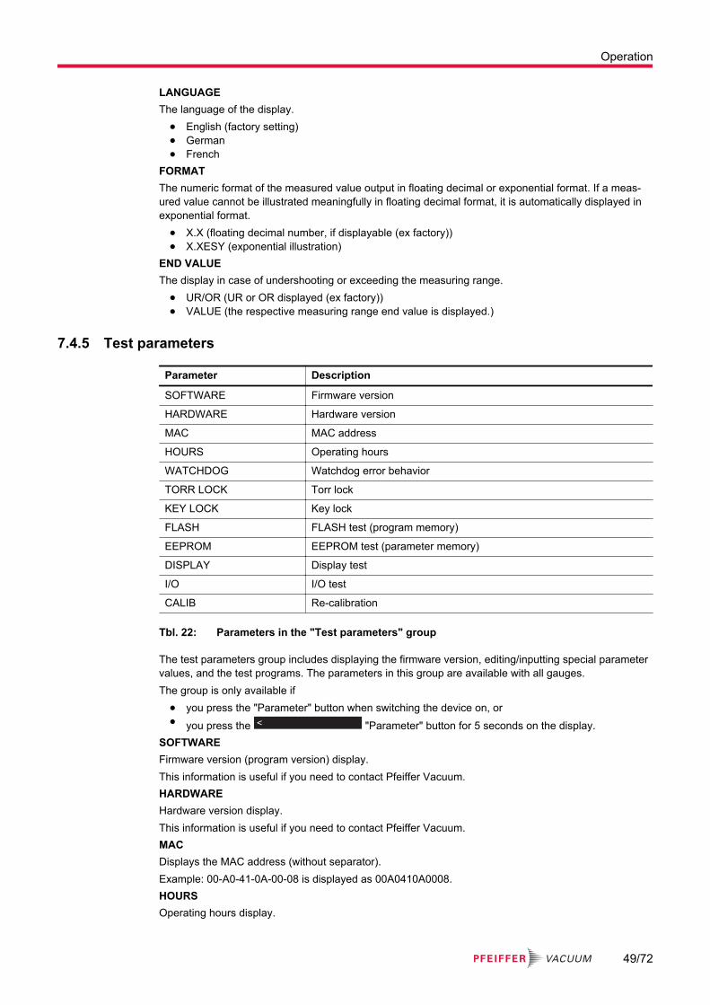
LANGUAGEThe language of the display.
● English (factory setting)● German● French
FORMATThe numeric format of the measured value output in floating decimal or exponential format. If a meas-ured value cannot be illustrated meaningfully in floating decimal format, it is automatically displayed in exponential format.
● X.X (floating decimal number, if displayable (ex factory))● X.XESY (exponential illustration)
END VALUEThe display in case of undershooting or exceeding the measuring range.
● UR/OR (UR or OR displayed (ex factory))● VALUE (the respective measuring range end value is displayed.)
7.4.5 Test parameters
Parameter Description
SOFTWARE Firmware version
HARDWARE Hardware version
MAC MAC address
HOURS Operating hours
WATCHDOG Watchdog error behavior
TORR LOCK Torr lock
KEY LOCK Key lock
FLASH FLASH test (program memory)
EEPROM EEPROM test (parameter memory)
DISPLAY Display test
I/O I/O test
CALIB Re-calibration
Tbl. 22: Parameters in the "Test parameters" group
The test parameters group includes displaying the firmware version, editing/inputting special parameter values, and the test programs. The parameters in this group are available with all gauges.The group is only available if
● you press the "Parameter" button when switching the device on, or● you press the < "Parameter" button for 5 seconds on the display.
SOFTWAREFirmware version (program version) display.This information is useful if you need to contact Pfeiffer Vacuum.HARDWAREHardware version display.This information is useful if you need to contact Pfeiffer Vacuum.MACDisplays the MAC address (without separator).Example: 00-A0-41-0A-00-08 is displayed as 00A0410A0008.HOURSOperating hours display.
Operation
49/72

WATCHDOGBehavior of system monitoring (Watchdog Control) in the event of an error.
● AUTO─ The system acknowledges a Watchdog malfunction message itself after 2 seconds (factory
setting).● OFF
─ The user must acknowledge a Watchdog malfunction message.TORR LOCKSuppression of the Torr unit of measure as a parameter value during setting. This function is disabled in the factory setting.KEY LOCKThe key lock prevents unintentional input in parameter mode and thus any malfunctions. This function is disabled in the factory setting.FLASHProgram memory test.
1x
Fig. 33: Program memory test
● RUNNING─ The test is running (very short).
● OK─ Test completed, no errors detected. An 8-digit checksum is then displayed, for example
FLASH 0x12345678.● ERROR
─ Test completed, errors detected. An 8-digit checksum is then displayed, for example FLASH 0x12345678.If the error occurs again when the test is repeated, you should contact your nearest Pfeiff-er Vacuum Service Center.
EEPROMParameter memory test.
1x
Fig. 34: Parameter memory test
● RUNNING─ The test is running.
● OK─ Test completed, no errors detected.
● ERROR─ Test completed, errors detected.
If the error occurs again when the test is repeated, you should contact your nearest Pfeiff-er Vacuum Service Center.
DISPLAYDisplay test.
Operation
50/72

1x
Fig. 35: Display test
After starting the test, all the display elements light up simultaneously for 10 s.I/OThe test program tests the relay switching function of the device.
NOTICEUnintentional results with controller connectedSwitch relay not dependent on pressure. Values below the intended measuring range, or starting the test program, can result in unintentional results at the connected controller, if the relay switches.► Unplug the connected measuring and control cable.► Prevent triggering of incorrect control commands or messages.
1x
Fig. 36: Test of relays in the device
The relays switch on and off cyclically. The display visually indicates the switching operations. The switching operations also emit a clearly audible sound. The contacts of the switching functions are avail-able at the "control" connection on the rear of the device. You can use an ohmmeter to check the func-tion.
● OFF─ All relays switched off
● REL1–4─ Relay switching function 1 to 4
● REL5–6─ Relay gauge S1 to S2
● REL7─ Malfunction relay
CALIBDate of next recalibration. When the set date is reached, a "RECALIB REQUIRED" message is dis-played.
7.5 Data logger mode
Parameter Description
DATE Current date
TIME Current time
INTERVAL Interval of measured data recording
DECIMAL POINT Decimal separator
FILE NAME File name
START/STOP Start/stop recording
DELETE Deletion of files with recorded measured data
Operation
51/72

Tbl. 23: Parameters in data logger mode
The data logger group includes● logging measured data onto a USB memory stick (USB interface type A).● deleting recorded measured data from the USB memory stick.
The group is only available if a USB memory stick (≤ 32 GB) formatted with the FAT file system (FAT32) is plugged in.
USB memory sticksThe device does not recognize all USB memory sticks, for instance if they do not comply with the USB standard. Try using a different memory stick first before you contact your nearest Pfeiffer Vacuum Service Center.
DATECurrent date in format YYYY-MM-DD.TIMECurrent time in format hh:mm [24 h].INTERVALInterval of measured data recording.
● 1 s─ Recording interval 1/s
● 10 s─ Recording interval 1/10 s
● 30 s─ Recording interval 1/30 s
● 1 min─ Recording interval 1/60 s
● 1 %─ Recording interval: With measured value changes ≥ 1 %
● 5 %─ Recording interval: With measured value changes ≥ 5 %
DECIMAL POINTDecimal point for the measured values with measured data recording (full stop or comma).The decimal separator is important for further processing with a spreadsheet program.FILE NAMEName of the measured data file max. 7 characters. The file extension is CSV.If the name is shorter than 7 characters, the device requires a space character for the remaining char-acters. After entering the 7th character, the display stops flashing. The device has stored the name and reverted to read mode.START/STOP
1x
1x
1x
Fig. 37: Start/stop measured data recording
Start/stop measured data recording.During measured data recording, the number of the corresponding measurement channel flashes."UP" arrow button = start saving. Recording is running, the display switches to "STOP" and the "DOWN" arrow flashes."DOWN" arrow button = stop saving. Recording stops, the display switches to "START" and the "UP" arrow flashes.
Operation
52/72

If the arrows are flashing on the display, the device does not automatically revert to measuring mode. You can press the "Parameter" button to quit write mode. The device then automatically reverts to measuring mode after approx. 10 seconds.DELETE
1x
Fig. 38: Delete files
Delete all measured data files (with CSV file extension) from the USB memory stick.● RUNNING
─ CSV files are being deleted.● DONE
─ CSV files have been deleted.
7.6 Setup mode
Parameter Description
SAVE Save all parameters
RESTORE Write all parameters to the device
FORMAT Format the USB memory stick (FAT32)
DELETE Delete files with stored parameters
Tbl. 24: Parameters in setup mode
This group allows● all parameters to be saved on a USB memory stick (USB interface type A).● all parameters to be loaded from a USB memory stick onto the device.● the formatting of a USB memory stick.● the deletion of files with stored parameters from the USB memory stick.
The group is only available if a USB memory stick (≤ 32 GB) formatted with the FAT file system (FAT32) is plugged in.SAVESave all the device’s parameters on a USB memory stick (file: SETUPxx.CSV). The device saves the threshold values and the offset in the unit of measure mbar or hPa.You can choose the file names from SETUP01 to SETUP99.
● RUNNING─ The device saves the CSV file.
● DONE─ The save operation is complete.
RESTORELoad all parameters from a USB memory stick onto the device. If you have not specified a unit of meas-ure in the CSV file for the threshold values and the offset, the device loads the values in mbar or hPa. Otherwise, the device explicitly requires a unit of measure in upper case letters for these values (MBAR, HPASCAL, TORR, PASCAL or MICRON) followed by a space character, e.g. 5.00-4 TORR or 0.0002 PASCAL.You can choose the file names from SETUP01 to SETUP99.
● RUNNING─ The device loads the CSV file.
● DONE─ Loading is complete.
Operation
53/72

● ERROR─ An error has occurred.
FORMAT
1x
Fig. 39: Formatting the USB memory stick
Format the USB memory stick.● RUNNING
─ Formatting is running.● DONE
─ Formatting is complete.DELETE
1x
Fig. 40: Delete parameter files from the USB memory stick
Delete all parameter files (ending with CSV) from the USB memory stick.● RUNNING
─ The device is deleting the files.● DONE
─ The device has deleted the files.
Operation
54/72

8 DecommissioningSwitching the device off
1. Switch off the device at the mains switch.2. For rack assembly: Switch off the device centrally via the switched mains distributor.3. Wait at least 10 seconds before switching it back on again, so that the device can reinitialize.
Decommissioning
55/72

9 MaintenanceMaintenance in the Pfeiffer Vacuum Service CenterPfeiffer Vacuum offers a complete maintenance service for all products.Pfeiffer Vacuum recommends: Contact your Pfeiffer Vacuum Service Center to ar-range the maintenance of defective products and components.
Cleaning in the Pfeiffer Vacuum Service CenterPfeiffer Vacuum recommends: Contact your nearest Pfeiffer Vacuum Service Cen-ter to arrange the cleaning of heavily-soiled products and components.
Do not forget the cleaningYou must ensure that you do not forget the cleaning step, even if you have con-structed the product in such a way that contamination is not easily detected.
Loss of warranty claimsThe following will result in the loss of the warranty:
● Damage to or removal of a closure seal● Opening the device during the warranty period
Contact the Pfeiffer Vacuum Service Center in the event of process-related shorter maintenance intervals.
First read through the sections completelyRead the section with the work instructions through completely first before you commence with work.
9.1 Cleaning the device
DANGERElectric shocks due to moisture penetrating into the deviceWater that has penetrated into the device results in personal injury through electric shocks.► Only operate the device in a dry environment.► Operate the device away from fluids and humidity sources.► Do not switch on the device if fluid has penetrated into it, instead contact Pfeiffer Vacuum Serv-
ice.► Always disconnect the current supply before cleaning the device.
WARNINGHealth hazards due to cleaning agentThe cleaning agents used cause health hazards.► When handling cleaning agents, observe the applicable regulations.► Adhere to safety measures regarding handling and disposal of cleaning agents.► Be aware of potential reactions with product materials.
Maintenance
56/72
NOTICEDamage caused by penetrating moisturePenetrating moisture, e.g. through condensation or dripping water, damages the device.► Protect the device against moisture penetrating.► Only operate the device in a clean and dry environment.► Operate the device away from fluids and humidity sources.► Take special precautions if there is a risk of dripping water.► Do not switch on the device if fluid has penetrated into it, instead contact the Pfeiffer Vacuum
Service Center.
NOTICEDamage caused by unsuitable cleaning agentsUnsuitable cleaning agents damage the product.► Do not use solvents as they attack the surface.► Do not use any aggressive or abrasive cleaning agents.
Cleaning the deviceRequired consumables
● Common cleaning agent (e.g. mild detergent).● Soft cloth1. Switch the device off and disconnect it from the network.2. Use a soft, damp cloth to clean the surfaces.3. Allow the surfaces to dry thoroughly after cleaning.
9.2 Replacing the batteryThe product contains a battery (type CR2032, service life > 10 years), in order to maintain the data in-tegrity of the real-time clock. A battery replacement is necessary if the real-time clock repeatedly dis-plays an incorrect date. To arrange for the battery to be replaced, you must contact your nearest Pfeiff-er Vacuum Service Center.
Maintenance
57/72

10 ErrorsThe error appears and the error relay opens.
Error cannot be eliminatedIf the error persists even after it has been acknowledged and/or the gauge has been replaced several times, please contact your nearest Pfeiffer Vacuum Service Center.
Defect Possible cause Remedy/acknowledgment
Display: SENSOR ERROR
Interruption or interference in the connection to the gauge (sensor error).
Acknowledge with the "Parameter" key.If the cause is not remedied, NO SENSOR or NO IDENTappears.
Display: WATCH-DOG ERROR
After switching off, the unit was switched on again too quickly.
Acknowledge with the "Parameter" key.If the watchdog is set to Auto, the device self-acknowledges after 2 s.The watchdog was tripped by a
serious electrical fault or operat-ing system error.
Display: UART ER-ROR
Error in the UART. Acknowledge with the "Parameter" key.
Display: PROGRAM CORRUPT
Error in program memory (FLASH).
Acknowledge with the "Parameter" key.
Display: DATA CORRUPT
Error in the parameter memory (EEPROM).
Acknowledge with the "Parameter" key.
Display: DISPLAY ERROR
Error in the display driver. Acknowledge with the "Parameter" key.
Display: A/D ER-ROR
Error in the A/D converter. Acknowledge with the "Parameter" key.
No supply to gauge Overcurrent protection (fuse pro-tection)
Switch off the deviceorUnplug the gauge connector
Tbl. 25: Errors
Errors
58/72

11 Shipping WARNING
Risk of poisoning from contaminated productsWhere products that contain harmful substances are shipped for maintenance or repair purposes, the safety of service personnel is at risk.► Comply with the instructions for safe shipping.
Instructions for safe shipping
Decontamination subject to chargePfeiffer Vacuum decontaminates products not clearly declared "Free of contamina-tion" at your expense.
1. Do not ship microbiological, explosive or radioactively contaminated products!2. Observe the shipping guidelines for the participating countries and transport companies.3. Designate the dangers on the outside of the packaging.4. Download the declaration of contamination. (Pfeiffer Vacuum Service).5. Always enclose a completed declaration of contamination!
Shipping
59/72
12 Disposal WARNING
Health hazard through poisoning from toxic contaminated components or devicesToxic process media result in contamination of devices or parts of them. During maintenance work, there is a risk to health from contact with these poisonous substances. Illegal disposal of toxic sub-stances causes environmental damage.► Take suitable safety precautions and prevent health hazards or environmental pollution by toxic
process media.► Decontaminate affected parts before carrying out maintenance work.► Wear protective equipment.
CAUTIONHealth hazard caused by environmentally hazardous substancesProducts, operating fluid, electric components, calibration gas residues (for example from test leaks) or similar pose health hazards.► Dispose of the environmentally hazardous substances in accordance with local regulations.► Dispose of calibration gas and test leaks in accordance with local regulations.
Dividing components► After disassembly, divide the components into the following categories with regard to disposal:
● contaminated components that had contact with process gases● non-contaminated components that had no contact with process gases
Disposal of contaminated components that have contact with process gases1. Dispose of the substances in a safe manner in accordance with the locally applicable regulations
if the process gases used were contaminated, e.g. radioactive, toxic, caustic or a microbiological manner.
2. Observe the environment and safety provisions of the respective country.Disposal of components that do not have contact with process gases
1. Separate the components according to their type of material:● electronic components● electrical components● battery and rechargeable batteries● mechanical components
2. Recycle the components.3. Dispose of the substances in a safe manner according to locally applicable regulations.4. Observe the environment and safety provisions of the respective country.
Disposal
60/72

13 Service solutions from Pfeiffer VacuumWe offer first class serviceLong vacuum component service life, coupled with low downtimes, are clear expectations that you have of us. We satisfy your needs with capable products and outstanding service.We are consistently striving to perfect our core competence, service for vacuum components. And our service is far from over once you’ve purchased a product from Pfeiffer Vacuum. It often enough really just begins then. In proven Pfeiffer Vacuum quality, of course.Our professional sales engineers and service technicians stand ready to provide hands-on support to you worldwide. Pfeiffer Vacuum offers a complete portfolio of service offerings, ranging from genuine spare parts right through to service agreements.Take advantage of Pfeiffer Vacuum ServiceWhether for preventative on-site service from our field service, fast replacement with as-new replace-ment products or repair in a Service Center close to you; you have various options for upholding your equipment availability. Detailed information and addresses can be found on our website in the Pfeiff-er Vacuum Service section.Advice on the optimum solution is available from your Pfeiffer Vacuum contact partner.For quick and smooth handling of the service process, we recommend the following steps:
1. Download the current form templates.
─ Declaration of Service Request─ Service Request─ Declaration of Contamination
a. Dismantle all accessories and keep them (all external mounted parts as valve, inlet screen, etc.).
b. Drain the operating fluid/lubricant as necessary.
c. Drain the cooling medium as necessary.
ANFORDERUNG SERVICE
ERKLÄRUNG KONTAMINIERUNG
2. Fill out the service request and the declaration of contamination.
3. Send the forms via email, fax or post to your local Service Center.
4. You will receive a response from Pfeiffer Vacuum.
Sending of contaminated productsNo units will be accepted if they are contaminated with micro-biological, explosive or radioactive sub-stances. If products are contaminated or if the declaration of contamination is missing, Pfeiffer Vacuum will contact the customer before starting maintenance. In addition, depending on the product and the level of contamination additional decontamination costs may be required.
Service solutions from Pfeiffer Vacuum
61/72

5. Prepare the product for transport in accordance with the details in the dec-laration of contamination.
a) Neutralize the product with nitrogen or dry air.
b) Close all openings with airtight blank flanges.
c) Seal the product in appropriate protective film.
d) Only pack the product in suitable, stable transport containers.
e) Observe the applicable transport conditions.
ERKLÄRUNG KONTAMINIERUNG
6 Affix the declaration of contamination to the outside of the packaging.
7 Then send your product to your local Service Center.
8 You will receive a confirmation message/a quotation from Pfeiffer Vacuum.
For all service orders, our General Terms and Conditions of Sales and Supply and General Terms and Conditions of Repair and Maintenance apply to vacuum equipment and components.
Service solutions from Pfeiffer Vacuum
62/72
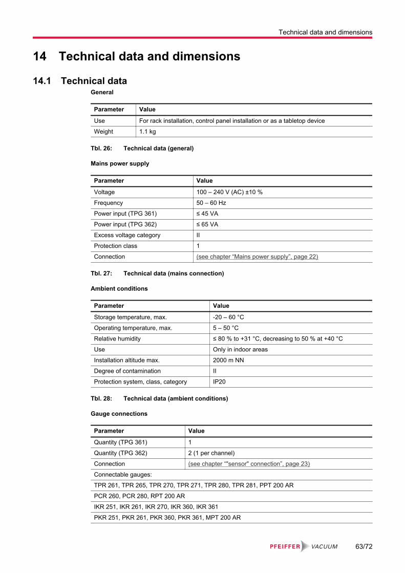
14 Technical data and dimensions
14.1 Technical dataGeneral
Parameter Value
Use For rack installation, control panel installation or as a tabletop device
Weight 1.1 kg
Tbl. 26: Technical data (general)
Mains power supply
Parameter Value
Voltage 100 – 240 V (AC) ±10 %
Frequency 50 – 60 Hz
Power input (TPG 361) ≤ 45 VA
Power input (TPG 362) ≤ 65 VA
Excess voltage category II
Protection class 1
Connection (see chapter “Mains power supply”, page 22)
Tbl. 27: Technical data (mains connection)
Ambient conditions
Parameter Value
Storage temperature, max. -20 – 60 °C
Operating temperature, max. 5 – 50 °C
Relative humidity ≤ 80 % to +31 °C, decreasing to 50 % at +40 °C
Use Only in indoor areas
Installation altitude max. 2000 m NN
Degree of contamination II
Protection system, class, category IP20
Tbl. 28: Technical data (ambient conditions)
Gauge connections
Parameter Value
Quantity (TPG 361) 1
Quantity (TPG 362) 2 (1 per channel)
Connection (see chapter “"sensor" connection”, page 23)
Connectable gauges:
TPR 261, TPR 265, TPR 270, TPR 271, TPR 280, TPR 281, PPT 200 AR
PCR 260, PCR 280, RPT 200 AR
IKR 251, IKR 261, IKR 270, IKR 360, IKR 361
PKR 251, PKR 261, PKR 360, PKR 361, MPT 200 AR
Technical data and dimensions
63/72

Parameter Value
IMR 265
PBR 260, HPT 200 AR
CMR 261 – CMR 275, CMR 361 – CMR 375
APR 250 – APR 267, CPT 200 AR
Tbl. 29: Technical data (gauge connections)
Gauge supply voltage
Parameter Value
Voltage +24 V (DC) ±5 %
Ripple < ±1 %
Current 0 – 1 A (per channel)
Power 25 W (per channel)
Fuse 1.5 A (per channel) with PTC element, self-resetting after switching off the device or un-plugging the gauge plug. The voltage supply meets the requirements of an protected extra-low voltage.
Tbl. 30: Technical data (gauge supply)
Operation
Parameter Value
Front panel (TPG 361) 3 control buttons
Front panel (TPG 362) 4 control buttons
Remote control RS-485 interface, USB type B interface, Ethernet interface
Tbl. 31: Technical data (operation)
Measured values
Parameter Value
Measuring ranges Gauge-dependent
Measuring error (amplification error) ≤ 0.01 % F.S. (typical), ≤ 0.10 % F.S. (over temperature range, time)
Measuring error (offset error) ≤ 0.01 % F.S. (typical), ≤ 0.10 % F.S. (over temperature range, time)
Measuring rate analog ≥ 100 / s
Display rate ≥ 10 / s
Filter time constant (slow) 750 ms (fg = 0.2 Hz)
Filter time constant (normal) 150 ms (fg = 1 Hz)
Filter time constant (fast) 20 ms (fg = 8 Hz)
Unit of measure mBar, hPa, Torr, Pa, Micron, V
Offset correction For linear gauges -5 – 110% F.S.
Calibration factor 0.10 – 10.00
A/D conversion Resolution 0.001 % F.S.
Tbl. 32: Technical data (measured values)
Technical data and dimensions
64/72

Switching functions
Parameter Value
Quantity (TPG 361) 2
Quantity (TPG 362) 4 (freely assignable)
Response time ≤ 10 ms, if the threshold value is near the measured value (note the filter time constant if there is a large difference).
Setting range Gauge-dependent
Hysteresis ≥ 1 % F.S. for linear gauges, ≥ 10 % of the measured value for logarithmic gauges
Tbl. 33: Technical data (switching functions)
Switching function relay
Parameter Value
Contact type Zero-potential two-way contact
Load max. 60 V (DC), 0.5 A, 30 W (ohmic)30 V (AC), 1 A (ohmic)
Service life (mechanical) 1 · 108 Switching cycles
Service life (electrical) 1 · 105 Duty cycles (at maximum load)
Contact settings (see chapter “"relay" connection”, page 24)
Connection
Tbl. 34: Technical data (switching function relay)
Error signal (error)
Parameter Value
Quantity, number 1
Response time ≤ 10 ms
Tbl. 35: Technical data (error signal (error))
Error signal relay
Parameter Value
Contact type Zero-potential two-way contact
Load max. 60 V (DC), 0.5 A, 30 W (ohmic)30 V (AC), 1 A (ohmic)
Service life (mechanical) 1 · 108 Switching cycles
Service life (electrical) 1 · 105 Duty cycles (at maximum load)
Contact settings (see chapter “"control" connection”, page 23)
Connection
Tbl. 36: Technical data (error signal relay)
Technical data and dimensions
65/72

Gauge control
Parameter Value
Switch on/off automatically Switch on/off threshold value adjustable(see chapter “Gauge control”, page 43)
Switch on/off via buttons (see chapter “Measuring mode”, page 36)
Switch on/off via "control" connection Switch-on criterion: Signal ≤ +0.8 V (DC)Switch-off criterion: Signal +2.0 – 5 V (DC) or input open(see chapter “"control" connection”, page 23)
switch on with mains voltage (see chapter “Gauge control”, page 43)
with pressure rise Switch-off threshold value adjustable(see chapter “Gauge control”, page 43)
Tbl. 37: Technical data (gauge control)
Analog output
Parameter Value
Quantity ((TPG 361) 1
Quantity ((TPG 362) 2 (1 per channel)
Voltage range 0 – +10 V (DC)If you have not connected a gauge to the respective meas-urement channel, the voltage at the analog output slowly ris-es to around 13.6 V.
Deviation from the display value ± 10 mV
Output resistance < 50 Ω
Measurement signal to pressure ratio Gauge-dependent
Connection (see chapter “"control" connection”, page 23)
Tbl. 38: Technical data (analog outputs)
RS-485 interface
Parameter Value
PROTOCOL ACK/NAK, ASCII with 3 character mnemonicsor PV protocol
Data format Two-way data traffic, 1 start bit, 8 data bits, 1 stop bit, no parity bit, no handshake
Baudrate 9600
Connection (see chapter “Connection "RS-485"”, page 25)
Tbl. 39: Technical data (RS-485 interface)
USB interface (type A)
Parameter Value
PROTOCOL FAT file systemFile processing in ASCII format
Tbl. 40: Technical data (USB interface (type A))
Technical data and dimensions
66/72

USB interface (type B)
Parameter Value
PROTOCOL ACK/NAK, ASCII with 3 character mnemonicsor PV protocol
Data format Two-way data traffic, 1 start bit, 8 data bits, 1 stop bit, no parity bit, no handshake
Baudrate 9600, 19200, 38400, 57600, 115200
Tbl. 41: Technical data (USB interface (type B))
Ethernet interface
Parameter Value
PROTOCOL ACK/NAK, ASCII with 3 character mnemonicsor PV protocol
Data format Two-way data traffic, 1 start bit, 8 data bits, 1 stop bit, no parity bit, no handshake
Baudrate 9600, 19200, 38400, 57600, 115200
IP address DHCP or manual inputPort: 8000 (static)
MAC address readable via "MAC" parameter
Tbl. 42: Technical data (Ethernet interface)
14.2 Dimensions70.8
55.9
122.5
128.5
218.5
203.5 2.5
111.6
Fig. 41: Dimensions TPG 361 (in mm)
Technical data and dimensions
67/72

70.8
55.9
122.5
128.5
218.5
203.5 2.5
111.6
Fig. 42: Dimensions TPG 362 (in mm)
Technical data and dimensions
68/72

15 Appendix
15.1 Units of pressure
Unit mbar bar Pa hPa kPa Torr / mm Hg
mbar 1 1 · 10-3 100 1 0.1 0.75
bar 1000 1 1 · 105 1000 100 750
Pa 0.01 1 · 10-5 1 0.01 1 · 10-3 7.5 · 10-3
hPa 1 1 · 10-3 100 1 0.1 0.75
kPa 10 0.01 1000 10 1 7.5
Torr / mm Hg 1.33 1.33 · 10-3 133.32 1.33 0.133 1
1 Pa = 1 N/m2
Tbl. 43: Units of pressure and their conversion
15.2 Gas throughputs
Unit mbar l/s Pa m3/s sccm Torr l/s atm cm3/s
mbar l/s 1 0.1 59.2 0.75 0.987
Pa m3/s 10 1 592 7.5 9.87
sccm 1.69 · 10-2 1.69 · 10-3 1 1.27 · 10-2 1.67 · 10-2
Torr l/s 1.33 0.133 78.9 1 1.32
atm cm3/s 1.01 0.101 59.8 0.76 1
Tbl. 44: Gas throughputs and their conversion
Appendix
69/72

4010094
ETL LISTED
The products TPG 361, TPG 362 and TPG 366
- conform to the UL standards
UL 61010-1 and UL 61010-2-030.
- are certified to the CAN/CSA standards
CAN/CSA C22.2 No. 61010-1-12 and CAN/CSA C22.2 No. 61010-2-030.

Declaration of conformity
We hereby declare that the product cited below satisfies all relevant provisions of the follow-ing EU Directives:
● Low voltage 2014/35/EC● Electromagnetic compatibility 2014/30/EU● Restriction of the use of certain hazardous substances 2011/65/EU
Total pressure measuring and control unitTPG 361 | TPG 362
Harmonized standards and applied national standards and specifications:DIN EN 61000-3-2:2015-03
DIN EN 61000-3-3:2014-03
DIN EN 61000-6-1:2007-10
DIN EN 61000-6-2:2006-03
DIN EN 61000-6-3:2011-09
DIN EN 61000-6-4:2011-09
DIN EN 61010-1:2011-07
DIN EN 61326-1:2013-07
Signature:
Pfeiffer Vacuum GmbHBerliner Straße 4335614 AßlarGermany
(Dr. Ulrich von Hülsen)Managing Director
Aßlar, 2018-04-16

*BG5500*
ed. D
- D
ate
1901
- P/
N:B
G55
00BE
N