Operating Instructions HERMA 400 - Üdvözöljük az ENDI...
106
Operating Instructions HERMA 400
Transcript of Operating Instructions HERMA 400 - Üdvözöljük az ENDI...

Operating Instructions
HERMA 400

PREFACE Operating Instructions HERMA 400
Preface
These operating instructions are to help you to safely set up your machine and operate it troublefree. You should read all of these instructions before starting the machine in order to get well acquainted with it.
We made an effort to describe all important points clearly and unambiguously.However, if you have any queries or suggestions for the development of these instructions please contact us.
HERMA GmbH, Technical Documentation
Explanation of symbols
!
!
!
i
Note
Contents subject to modifications.
No part of this documentation may be reproduced or processed, copied, or distributed with the help of electronic systems in any form without prior written permission of HERMA GmbH
Version 3.15 GB/US (150708) 2008 © Copyright HERMA GmbH
DANGER: Indicates a potentially hazardous situation which, if not avoided, will result in death or serious injury.
CAUTION: Indicates a potentially hazardous situation which, if not avoided, will result in minor or moderate injury and physical damage.
Indicates that the operation must be performed without fail / the information is mandatory to take notice of.
Indicates that the operation is prohibited
Indicates information you should take notice of.
2

Operating Instructions HERMA 400 CONVENTIONS
Conventions
Elements of the H400 control are designated and depicted in these instructions as follows:
Switch-on key
Manual feed key
Function key
LED (on)
LED (blinks)
LED (off)
Minus key
Plus key
Enter key
Find further explanation on these elements in section 5.1.1.
b3

Operating Instructions HERMA 400 TABLE OF CONTENTS
Table of Contents
1 Safety 91.1 Important Safety Precautions 91.2 Safety notes 11
2 Transport, Installation and Connection 132.1 Transporting the machine 132.2 Installing the machine 132.3 Electrical connection / Power supply 142.3.1 Connections 14
3 Operational range 153.1 Proper use of the machine 153.2 Adhesive labels 15
4 Threading the Label Web 174.1 Label web insertion schemes 174.1.1 Right-hand applicator with standard dispensing plate 174.1.2 Left-hand applicator with standard dispensing plate 174.1.3 Right-hand applicator with pivot beak 184.1.4 Left-hand applicator with pivot beak 184.1.4.1 Detailed illustrations 184.1.5 Right-hand applicator with dispensing plate with spring-loaded roller, 75° angular 194.1.6 Left-hand applicator with dispensing plate with spring-loaded roller, 75° angular 194.1.7 Winder system, left-hand applicator 204.1.8 Winder system, right-hand applicator 21
5 Putting into Operation and Operation 235.1 Operation / Settings via the H400 control 245.1.1 Design 255.1.1.1 Key pad 255.1.1.2 Display 275.1.2 Function diagram 275.1.3 End of reel and diminishing reel (internal) 285.2 Overview display structure HERMA 400 295.3 The display’s Quick Menu 305.3.1 Start delay applicator (Quick Menu parameter) 315.3.2 Stop delay label (Quick Menu parameter) 315.3.3 Speed of the applicator (Quick Menu parameter) 325.3.4 Speed of the product (Quick Menu parameter, optional) 325.4 Potentiometers 325.5 The display’s configuration menu 335.5.1 Calling up 335.5.2 Design 335.5.3 Menu 100 Basic data 335.5.3.1 120 Master encoder Pulses / revolution 33
5

TABLE OF CONTENTS Operating Instructions HERMA 400
5.5.3.2 121 Master encoder Distance / revolution 345.5.3.3 122 Master encoder Start compensation 345.5.3.4 123 Master encoder Stop compensation 345.5.3.5 124 Master encoder Mini loop on/off 345.5.3.6 125 Master encoder Mini loop start delay 345.5.3.7 126 Master encoder Mini loop size 345.5.3.8 115 Master enc. transfer 345.5.3.9 116 Master enc. transfer Label pos. difference 355.5.3.10 117 Masterenc. transfer Start compensation 355.5.3.11 140 Start signal 355.5.3.12 141 Mark field 1 355.5.3.13 142 Mark field 2 355.5.3.14 143 Mark field 3 355.5.3.15 144 Start inhibit distance 355.5.3.16 160 Multi labelling 365.5.3.17 161 Multi labelling Number of labels 365.5.3.18 130 Stop signal 365.5.3.19 131 Mark field 1 365.5.3.20 132 Mark field 2 365.5.3.21 133 Mark field 3 365.5.3.22 134 Stop inhibit distance 375.5.3.23 135 Hole inhibit distance 375.5.3.24 190 Printer on/off 375.5.3.25 194 Printer Start delay 375.5.3.26 195 Printer Print time 375.5.3.27 196 Stop at missing label 375.5.4 Menu 200 Transfer data 385.5.4.1 210 Pivot beak on/off 385.5.4.2 211 Pivot beak Type 385.5.4.3 212 Pivot beak Start delay 395.5.4.4 213 Pivot beak Activation time 395.5.4.5 214 Pivot beak Stop delay 395.5.4.6 225 Moving beak Label start delay 395.5.4.7 227 Moving beak Work pos. return del. 395.5.4.8 229 Moving beak Home pos. reached 395.5.4.9 236 Transfer unit Work pos. reached 405.5.4.10 237 Transfer unit Work pos. return del. 405.5.4.11 238 Transfer unit Blow 405.5.4.12 239 Transfer unit Home pos. reached 405.5.4.13 239 Transfer unit After blow 405.5.4.14 280 Label check on / off 405.5.4.15 284 Label check aft. feed 405.5.4.16 285 Lab. check aft. transf. 405.5.4.17 286 Label check start delay 415.5.5 Menu 400 Formats 415.5.6 Menu 500 Counters 415.5.7 Menu 900 System 415.5.7.1 910 Rotate display 415.5.7.2 911 Contrast 415.5.7.3 912 Sprache / Language 415.5.7.4 950 Bus address (RS485) 415.5.7.5 952 Display add. output 41
6 Overview and sub-assemblies 436.1 Overview 436.1.1 Function 436.2 Sub-assemblies 446.2.1 Standard unwinder 45
6

Operating Instructions HERMA 400
6.2.2 Motorized unwinder 496.2.3 Loop-type unwinder 516.2.4 Label web brake 546.2.5 Label sensor FS01 566.2.6 Label sensor optoelectronic 586.2.7 Dispensing systems 606.2.7.1 Rigid/Straight dispensing plates 606.2.7.2 Dispensing plate, 15° angular 616.2.7.3 Pivot beak / Application unit 626.2.7.4 Moving beak 636.2.8 Transfer systems 646.2.8.1 Telescope 646.2.9 Drive/Transport roller 656.2.10 Backing paper take-up unit standard 666.2.11 Backing paper take-up unit motorized 71
7 Troubleshooting 737.1 Indication of malfunctions 737.1.1 List of malfunctions (indicated via display) 747.1.1.1 SM107 End of label web 747.1.1.2 SM108 Dispensing beak does not reach home position 747.1.1.3 SM109 Dispensing beak does not leave home position 747.1.1.4 SM110 Dispensing beak does not reach work position 747.1.1.5 SM111 Dispensing beak does not leave work position 747.1.1.6 SM113 Transfer unit does not reach home position 747.1.1.7 SM114 Transfer unit does not leave home position 747.1.1.8 SM115 Transfer unit does not reach work position 757.1.1.9 SM116 Transfer unit does not leave work position 757.1.1.10 SM119 Label check Error after label feed 757.1.1.11 SM120 Label check Error after label transfer 757.1.1.12 SM148 Missing label series fault (web break?) 757.1.1.13 SM153 Multi labelling Start sequence too close 757.1.1.14 SM164 Start signal Sensor mark not detected 757.1.1.15 SM165 Roller unit Communication error 757.1.1.16 SM166 Applicator Communication error 757.1.1.17 SM167 Roller unit Error 757.1.1.18 SM168 CAN connection Disconnect! 767.1.1.19 SM169 Firmware update required! 767.1.1.20 SM181 Chip changed! 767.1.1.21 SM199 CAN communication no CAN module detected 767.1.1.22 SM910 Drive failure Low voltage 767.1.1.23 SM911 Drive failure High voltage 767.1.1.24 SM912 Drive failure High temperature 767.1.1.25 SM913 Drive failure Overload (period) 767.1.1.26 SM914 Drive failure 767.1.1.27 SM917 Drive failure Powerfail 767.1.1.28 SM918 Drive failure 767.1.1.29 SM919 Drive failure Low voltage (peak) 767.1.1.30 SM920 Drive failure Overload (peak) 777.1.1.31 SM921 Drive failure 777.1.1.32 SM922 Drive failure 777.1.1.33 SM923 Drive failure 777.1.1.34 SM924 Drive failure Overload 777.1.1.35 SM925 CAN communication disturbed 777.1.2 Malfunction table (LED indication) 787.1.2.1 Remedy of malfunctions 797.1.3 Error blink codes with PLC connection 79
7

Operating Instructions HERMA 400
7.2 Other malfunctions 807.3 Replace the drive unit 827.3.1 Remove the drive unit 827.3.2 Ship the drive unit 847.3.3 Mount the drive unit 847.4 Technical Service 84
8 Cleaning and maintenance 85
9 Technical Data 879.1 Inputs / outputs (X10) (option, standard signals) 899.2 Inputs / outputs (X19) (option, extended signals) 90
10 Declaration of Conformity / Manufacturer 91
11 Spare parts 93
Index 105
8

1 Safety
This machine complies with the essential safety and health requirements of the Machinery Directive 98/37/EC.
1.1 Important Safety Precautions
DANGER
Use HERMA 400 applicators on TN mains networks only.
Failure to observe this instruction could result in electric shocks, injuries and/or fire.
!
Install machine to a professionally installed and earthed socket.
Failure to observe this instruction could result in electric shocks, injuries and/or fire.
!
Before working on parts of the electrical equipment disconnect the machine from mains.
Failure to observe this instruction could result in electric shocks and injuries.!
Wait for at least five minutes before opening the housing or touching connector pins when cutting the applicator off mains.
Failure to observe this instruction could result in electric shocks and injuries.!
Do not expose the cables to sharp edges, excessive pressing forces, heavy loads or pinching forces.
Failure to observe this instruction could result in electric shocks, malfunction and/or damages.
!
Install an external emergency stop device so that you can shut off power in any emergency cases.
Failure to observe this instruction could result in injuries, electric shocks, fire, malfunction and/or mechanical damages!
Read before use!
9
1 SAFETY Operating Instructions HERMA 400
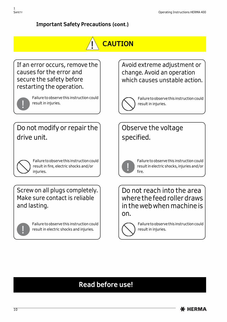
Important Safety Precautions (cont.)
CAUTION
If an error occurs, remove the causes for the error and secure the safety before restarting the operation.
Failure to observe this instruction could result in injuries.!
Avoid extreme adjustment or change. Avoid an operation which causes unstable action.
Failure to observe this instruction could result in injuries.
Do not modify or repair the drive unit.
Failure to observe this instruction could result in fire, electric shocks and/or injuries.
Observe the voltage specified.
Failure to observe this instruction could result in electric shocks, injuries and/or fire.!
Screw on all plugs completely. Make sure contact is reliable and lasting.
Failure to observe this instruction could result in electric shocks and injuries.!
Do not reach into the area where the feed roller draws in the web when machine is on.
Failure to observe this instruction could result in injuries.
Read before use!
10

1 Operating Instructions HERMA 400 SAFETY
1.2 Safety notes
! Pay attention to the following basic safety notes:
• Check operatability of protective equipment before setting into operation for the first time.
• Check operatability of protective equipment each time before setting to work.
• Non-operational protective equipment has to be replaced or repaired immediately.
• Technical status of protective equipment has to be inspected by competent staff on a regular basis, at least once a year.
• If safe operation of the machine can no longer be guaranteed it has to be put out of action immediately and be secured against further use.
• Machine may be operated by trained staff only. Carry out supplementary training.
• Give instructions for safe operation.
• Process only products that are suitable for the machine.
• Safety switches must not be bypassed.
• The method of cleaning given in this manual must be observed.
• Use original spare parts and accessories only.
• Machine must not be modified.
• Carefully store these operating instructions. On reselling the machine this manual must be passed on to the new owner.
Attention: The user is solely responsible for injuries or damage caused by improper use that is not in accordance with the instructions in this manual.!
Read before use!
11

2 Transport, Installation and Connection
2.1 Transporting the machine
When transporting the machine with the help of a fork lifter/lift-truck observe the following:
2.2 Installing the machine
If you should notice damage due to transport when you unpack the machine inform your HERMA sales office immediately.
! • Means of transport has to be approved for machine weight.
• Safety regulations for transporting and lifting of weights must be observed.
• The forks must be passed through between machine feet. Pay attention to the center of gravity of the machine.
• The forks must jut out from the opposite side of the machine.
! • ATTENTION: USE THE MACHINE IN DRY ROOMS.
• Machine has to be installed such that it is stable and secure.
WARRANTY
Important: Opening the screws at the front of the drive unit will void the warranty! i
13

2 TRANSPORT, INSTALLATION AND CONNECTION Operating Instructions HERMA 400
2.3 Electrical connection / Power supply
2.3.1 Connections
The following connections are available at the HERMA 400 applicator (depending on the configuration):
X14 – Serial OUT X16 – Labelling start X19 – Inputs/Outputs (ext. signals) X10 – Inputs/Outputs (stand. signals) / signal column (optional) X12 – Power supply
* X16 as special case, if X10/X19 occupied and separate start signal required . Impossible with .
** X16 as start signal, if X10/X19 are free.
See chapter 9 for the assignment of connectors X10 and X19 (if available).
!
! • HERMA 400 applicators must be used on TN mains networks only.
• Connect the machine to AC mains only and verify whether your line voltage meets the voltage given on the type plate.
• The machine must be connected to a professionally installed and earthed socket or must be professionally connected in the control box of the corresponding machine.
• Work on electrical components may only be carried out by an authorized person observing the relevant safety regulations.
• Before working on parts of the electrical equipment disconnect the machine from mains!
• When cutting the HERMA 400 applicator off mains you must wait for at least five minutes before opening the housing or touching connector pins. RESIDUAL VOLTAGES!
X14 ( ) /(X16 (special)*)
X16 ( , , ) / X19 ( , , , )**
X10 ( , , , )
X12
X13 (all types)
X11 ( , , )
Shown here: left-hand appl.; Right-hand appl.: mirror img.
X13 – Serial IN X11 – Master encoder
X17 – Pivot beak/ Printer
X15 – Label sensor
X17
X15
i All plugs are secured with coupling rings.Do not chock coupling ring when screwing it onto socket, as the thread may be damaged or rendered unusable. Screw on completely to make sure contact is reliable and lasting.
14

3 Operational range
3.1 Proper use of the machine
Your labeller HERMA 400 is an electronically driven machine suitable for labelling various products with different types of adhesive labels.
With this applicator you can unwind label reels and rewind the backing paper.
If required the labeller can be equipped with a printing unit so that you can print on your label e.g. lines of text, varying data, bar codes, and batch numbers.
Other purposes than those described above, especially winding other material than label reels, are not intended and are prohibited.
3.2 Adhesive labels
Winding outside
1 Label reel 2 Reel core 3 Label 4 Backing paper
3+4 Label web
Winding inside
1
2
3
4
1
23
4
15

3 OPERATIONAL RANGE Operating Instructions HERMA 400
Label l ing Systems
www.herma.com [email protected]
16

4 Threading the Label Web
4.1 Label web insertion schemes
The following schemes show how to insert the label web with the most common standard applicators. A separate insertion scheme is provided for applicator configurations other than shown here . As the case may be, this scheme may also be attached to the machine.
4.1.1 Right-hand applicator with standard dispensing plate
4.1.2 Left-hand applicator with standard dispensing plate
Caution: Before threading the label web make sure the applicator / machine is switched off.
!
O I
O = Außenwicklung / outside windingI = Innenwicklung / inside winding
681297
OI
O = Außenwicklung / outside windingI = Innenwicklung / inside winding
681296
17

4 THREADING THE LABEL WEB Operating Instructions HERMA 400
4.1.3 Right-hand applicator with pivot beak
4.1.4 Left-hand applicator with pivot beak
4.1.4.1 Detailed illustrations
OI
O = Außenwicklung / outside windingI = Innenwicklung / inside winding
681299
O
O = Außenwicklung / outside windingI = Innenwicklung / inside winding
681298
I
Detail dispensing plate Detail pivot beak
Detail dispensing plate, 75° angular
18

4 Operating Instructions HERMA 400 THREADING THE LABEL WEB
4.1.5 Right-hand applicator with dispensing plate with spring-loaded roller, 75° angu-lar
4.1.6 Left-hand applicator with dispensing plate with spring-loaded roller, 75° angular
Further to these standard layouts there are seven variants each when using the winder system (motorized unwinder and rewinder, with or without loop-type unwinder), the arrangements of which including web path is shown in the following illustrations.
O
I
I = Innenwicklung / inside winding
681300
O = Außenwicklung / outside winding
O
I
I = Innenwicklung / inside winding
681301
O = Außenwicklung / outside winding
19

4 THREADING THE LABEL WEB Operating Instructions HERMA 400
4.1.7 Winder system, left-hand applicator
*
* The winder system is a moduar system consisting of the individual components of unwinder, loop-type unwinder and backing paper take up unit (rewinder), each of which is motor driven . See sections 6.2.2, 6.2.3 and 6.2.11.
L1 L2 L3
L4 L5
L6 L7
20

4 Operating Instructions HERMA 400 THREADING THE LABEL WEB
4.1.8 Winder system, right-hand applicator
R1 R2 R3
R4 R5
R6 R7
21

4 THREADING THE LABEL WEB Operating Instructions HERMA 400
Label l ing Systems
www.herma.com [email protected]
22

5 Putting into Operation and Operation
>Connect power plug with mains.
> Press switch-on key 1 at the applicator. The machine is ready to operate.
Pressing button 2 will dispense a label.
Pressing button 3 twice (quickly) will activate or deactivate the optional printer. For more functions of this key see section 5.1.1.1 on page 25.
i Labellers which are part of a larger machine structure are usually switched on with the main switch for the entire setup (see also separate manual). Single labellers are put into operation as shown here.
1
2
3
Important: When inserting a new label reel always dispense at least two labels manually with the help of the key ! This will teach in the label length / max. label cycle.
!
23

5 PUTTING INTO OPERATION AND OPERATION Operating Instructions HERMA 400
5.1 Operation / Settings via the H400 control
CONVENTIONS
Elements of the H400 control are designated and depicted in this chapter as follows:
Switch-on key
Manual feed key
Function key
LED (on)
LED (blinks)
LED (off)
Minus key
Plus key
Enter key
Find further explanation on these elements in section 5.1.1.
24

5 Operating Instructions HERMA 400 PUTTING INTO OPERATION AND OPERATION
5.1.1 Design
Applicators HERMA 400 are operated via the keys of the key pad and the display. The display allows entry and adjustment of applicator parameters. Basic values, such as e.g. the start delay of the applicator, may be set either here or as well via optional potentiometers (in an external housing or in the control box).
5.1.1.1 Key pad
Applicator ON/OFFThe LED of the key is on if the drive is ON.
(Function available if not jumper „Remote“ is set on X27. In that case switching on/off would
be effected via pin X10.6)
Manual feedingYou can manually feed a label by pressing this key.
Important: When inserting a new label reel always dispense at least two labels manually with the help of the key !
(Function available if jumper „Feed“ is set on X27. If the jumper is not set feeding can be
effected via external signal only)
Function keyThere are several functions for this key (see following table).
Keys of the key pad have the following function (provided the applictor is not connected to a PLC; in that case the functions of the keys may be disabled. See the respective remark.):
Key pad Display
25

5 PUTTING INTO OPERATION AND OPERATION Operating Instructions HERMA 400
(2x)Printer ON/OFFAn optional printer can be switched on and off with the function key, pressing it quickly two times („double tip“).If the printer is ON the function „compensate for missing labels“ is active at the same time. That means, missing labels on the web will be detected automatically and the web always stopped in correct position such that imprint and, as the case may be, control cycles will be effected on every label.The LED of the key is on if the printer is on.
+ Switch on the drive‘s permanent run mode This operating mode is required, e.g., to determine the applicator‘s speed.
openIMPORTANT:Open lever first (nip roller)!
The current speed is indicated and may be adjusted as required via the display parameter for the speed (see below in section 5.3.3, page 32).
In order to stop the permanent run mode press one of the keys or . The permanent run mode is also stopped if the label sensor can notice a change (label transport).
Do not forget to close the lever (see picture above) when you are finished.
Escape function in display menusPressing this key in a display menu will get you back to the next higher level, as far as to the basic display image (see section 5.1.1.2, page 27). In the Edit mode (see section 5.3) any changes will be discarded.Make sure to press the key only once since otherwise the status of the printer and the function „compensate for missing labels“ will be changed!
i When using the applicator in a machine with superordinate control which has its own user interface (e.g. a touch panel) the Technical Service can deactivate the functionality of the display.
26

5 Operating Instructions HERMA 400 PUTTING INTO OPERATION AND OPERATION
5.1.1.2 Display
The display is activated with applying mains and will show one of two possible variants of the basic display image:
is off is on
This basic display image will be shown automatically if no key is pressed at the display for two minutes or if the user actuates the function key several times in a menu or in the edit mode.
The applicator type will be indicated in the basic display image with a corresponding letter: F (Fix ), E (Econ ), I (Idea ), V (Vario ), VM (Vario M ), P (Premium ), PPS (Premium Plus Serial ).
The current software version is indicated in the next line (this may be required by the Technical Service).
Inputs for start signal and label sensor are indicated via symbols in the right bottom corner of the display: = startsignal is applied, = label sensor currently on label (paper).
For a further description see section 5.3, page 30, and following.
5.1.2 Function diagram
Functions in the H400 applicator are as follows (pivot beak and printer are options):
= Start delay, = Stop delay
Standby
H400 VVz.xx.yy
Select
Ready
H400 VVz.xx.yy
Select
Transport
Pivot beak
Printer
Start
Stop signal
t4 = 20 msec
27

5 PUTTING INTO OPERATION AND OPERATION Operating Instructions HERMA 400
5.1.3 End of reel and diminishing reel (internal)
Trigger For calculating the label supply the label transport may be triggered via the START input (normal production), however transport via the key will also be part of the calculation. Take note of the fact, though, that messages on end of reel will be acknowledged with pressing the key .
Minimum transport
Calculating the label supply can be done not before at least approx. 4 m (157“) of label web were transported (for triggering end of reel approx. 400 mm (16“) are sufficient). This minimum transport must be effected each time after the applicator was switched off.
Warning A warning (DIM signal) is triggered if the width of the label web falls below approx. 16 mm / 0.6“ (diameter core (=76 mm/3“) + label web is below approx. 108 mm / 4.3“).
End of reel End of reel (END signal) is triggered if the label supply is used up, however not before a minimum transport of approx. 400 mm / 16“ (with preceding DIM signal after 150 mm / 5.9“ already).
End of reel without signal
If with unfavourable condition end of reel cannot be calculated the applicator will stop with a series fault of the label sensor.
The functions of diminishing reel and end of reel may be integrated in the unwinder, i.e., no external sensors are used but the label supply calculated via internal logic.
Prerequisite for this type of sensing is that the disc for taking up the label reel actuallys rotates, i.e., the reel definitely must be clamped firmly (use appropriate sleeve, turn handle of unwinder completely to the right).
In order to have this logic function correctly the following must also be observed:
TESTING THE FUNCTION
• The outputs for diminishing reel (DIM) and end of reel (END) are „high“ active, i.e., END=24V=end of reel, END=0V=no end of reel (or less than 4 m / 157“ of web transport was effected).
• Insert a label reel with low label supply, at least, however, approx. 5 m / 197“ of label web
• Dispense labels (observe above prerequisites (preferably transport labels via the START input instead of via the key))
28

5 Operating Instructions HERMA 400 PUTTING INTO OPERATION AND OPERATION
5.2 Overview display structure HERMA 400
Standby / Ready
Quick menu:
Start delay Stop delay Label speed Product speed Configuration
010 020 030 035 090
previously: potentiometers Password
...printer, master encoder... 100 Basic data
...pivot beak, moving beak... 200 Transfer data
At a later point of time 400 Formats
At a later point of time 500 Counters
...rotate display, language... 900 System
29

5 PUTTING INTO OPERATION AND OPERATION Operating Instructions HERMA 400
5.3 The display’s Quick Menu
As soon as the key is pressed while the basic display image is shown all parameters and submenus of the so-called Quick Menu are shown. In this Quick Menu you will find the basic values for the applicator’s start delay, the labels’ stop delay, the applicator’s speed, as the case may be the product’s speed, and the configuration menu with further parameters.
NAVIGATION
The last line of a (standard) parameter entry is made up as follows:
Select
Change between parameters with the keys and , in both directions (i.e. from the last entry with to the first on, or with from the first entry to the last one). The key calls up the edit mode (for modifying values).
EDIT MODE
After pressing the enter key (calling up the edit mode) the last line changes as follows:
Edit OK
In the edit mode values are increased or decreased with the help of the keys and . With Quick Menu parameters changes are effected immediately so that the effect of the change can be checked for without any delay. If no key is pressed for two minutes the basic display image (see above) is shown and the value that was used last is kept set. With all other parameters changes are discarded if no key is pressed for two minutes.
Before two minutes have passed without any keypress the key saves the (modified) value and shows the original parameter entry. Normal navigation is active.
Modification of a value after pressing the enter key is symbolized by showing a graphical OK symbol (light tick in black circle) for a short moment.
Pressing the function key (several times) will leave the parameter entry or the edit mode (with any changes discarded) and the basic display image (see above) is shown.
30

5 Operating Instructions HERMA 400 PUTTING INTO OPERATION AND OPERATION
5.3.1 Start delay applicator (Quick Menu parameter)
010
2.0 mm Select
Range: , 0–120 mm, 0–400 mm, , 0–800 mm (no function with and )
This basic value determines the delay between start signal and actual start of label transport. Thus, for example, the label‘s position on the product can be altered. Note: In conjunction with moving beak and transfer unit this value is given in milliseconds and defines the delay between product detection and starting the dispensing/transfer cycle.
With activated multi labelling (section 5.5.3.16, parameter 160) there is a separate start delay for every label, indicated with a corresponding digit beside the symbol.
Take note of the fact that depending on what is entered as the maximum product speed (parameter 113) the range of values (minimum value) changes for this parameter.
5.3.2 Stop delay label (Quick Menu parameter)
020
4.0 mm Select
Range: , , 0–60 mm, , , 0–400 mm (no function with )
This value determines the stop position of the label at the dispensing beak (see „Positioning the label“ in section 6.2.5 or 6.2.6 (pages 56 / 58). Note: if several labels are dispensed per labelling cycle this value might need to be decreased!
With activated twin labelling (section 5.5.3.16, parameter 160) there is a separate stop delay for both labels, indicated with a corresponding digit beside the symbol. With multi labelling with more than two labels the stop delay is identical for all labels.
Take note of the fact that depending on what is entered as the maximum label speed (parameter 112, for Technical Service only) the range of values (minimum value) changes for this parameter.
31

5 PUTTING INTO OPERATION AND OPERATION Operating Instructions HERMA 400
5.3.3 Speed of the applicator (Quick Menu parameter)
030
36.0 m/min Select
Range: 4/8/12 m/min, 3–20, 3–30, 3–40, 3–80, , 0–120 m/min
With the help of this parameter the speed of the label web can be adjusted. Minimum and maximum speeds correspond to the performance of the drive used. When using a master encoder this parameter will adjust the speed for manual feeding (after pressing the key ).
5.3.4 Speed of the product (Quick Menu parameter, optional)
035
120.0 m/min Select
Range: Max. 2000.0 m/min.
With the help of this parameter the speed of the product to be labelled can be adjusted.
The speed can be adjusted, i.e. this parameter is available, for all application types except for rigid beak, pivot beak, and type 211. When using a master encoder the product speed can only be read.
Specifying the product speed may be required if there is a difference between product and label speeds. In such case specifiying the product speed can ensure a highest possible positioning accuracy.
5.4 Potentiometers
Basic values of the applicator may optionally be adjusted via potentiometers as well. In that case these values can be adjusted via display only if the voltage at the analog input is less approx. 0.1V. Expressed in other words: in order to be able to adjust these values via display potentiometers must be set to 0 (zero). If the voltage at the analog input is high enough this will be shown in the display:
Analog
instead of Select
The corresponding value can be read at but not be modified via the display.
32

5 Operating Instructions HERMA 400 PUTTING INTO OPERATION AND OPERATION
5.5 The display’s configuration menu
In order to avoid incorrect entries the configuration menu can be called up only after entering a special key combination. There is a differentiation between access priorities, i.e. simple parameters can be displayed and modified with the key combination for operators, more sensitive parameters only with the key combintion for technicians.
Above that there are parameters that are factory set and can only be changed by the Technical Service. Depending on such parameters some of the following parameters will be / will not be shown. There are hints in the corresponding parameter descriptions.
5.5.1 Calling up
Operator (password level 1 (PWL1) + 3x + 2x +
Technician (password level 2 (PWL2) + 3x + 3x + 1x +
5.5.2 Design
The configuration menu is divided up into several submenus:
Basic data Transfer data Formats Counters System
5.5.3 Menu 100 Basic data
5.5.3.1 120 Master encoder Pulses / revolution
This parameter will appear only if parameter 110 (available only for Technical Service) is set to „02 Master encoder“.
Adjusting the pulses/increments emitted per revolution of the master encoder. See the indication at the master encoder.
090
Select
! Make these key combinations available only to authorized personnel. Careless handling of the configuration menu parameters may severely impair the applicator’s function.
33

5 PUTTING INTO OPERATION AND OPERATION Operating Instructions HERMA 400
5.5.3.2 121 Master encoder Distance / revolution
This parameter will appear only if parameter 110 (available only for Technical Service) is set to „02 Master encoder“.
Adjusting the distance of the web covered per revolution of the master encoder.
5.5.3.3 122 Master encoder Start compensation
This parameter will appear only if parameter 110 (available only for Technical Service) is set to „02 Master encoder“. With PWL2 only.
Setting the dead time of the start sensor in order to compensate for the resulting delay.
5.5.3.4 123 Master encoder Stop compensation
This parameter will appear only if parameter 110 (available only for Technical Service) is set to „02 Master encoder“. With PWL2 only.
Setting the dead time of the stop sensor (label sensor) in order to compensate for the resulting delay.
5.5.3.5 124 Master encoder Mini loop on/off
This parameter will appear only if parameter 110 (available only for Technical Service) is set to „02 Master encoder“. With PWL2 only.
Switching the mini loop on or off. This mini loop is built after a delay (to be set via parameter 125) by accelerating the web for a short time (distance to be set via parameter 126). The mini loop reduces the tension load of the web.
5.5.3.6 125 Master encoder Mini loop start delay
This parameter will appear only if parameter 110 (available only for Technical Service) is set to „02 Master encoder“ and parameter 124 is set to „On“. With PWL2 only.
The delay in mm web transport after which the mini loop is built.
5.5.3.7 126 Master encoder Mini loop size
This parameter will appear only if parameter 110 (available only for Technical Service) is set to „02 Master encoder“ and parameter 124 is set to „On“. With PWL2 only.
The distance in mm on which the mini loop is built.
5.5.3.8 115 Master enc. transfer
This parameter will appear only if parameter 110 (available only for Technical Service) is set to „02 Master encoder“. With PWL2 only. this and the two following parameters are for all application types except for rigid beak, pivot beak and type 211.
The dead time of a unit (e.g. transverse transfer unit) can be determined and compensated with the help of this parameter, in conjunction with parameter 116.
Production: The normal setting for production, without determining the dead time.
Test speed low: Select this setting and label a product at slow test speed.
Test speed fast: Select this setting and label the same product at high test speed.
34

5 Operating Instructions HERMA 400 PUTTING INTO OPERATION AND OPERATION
Dead time calculation: Select this setting to enter in parameter 116 the difference / the distance between the two labels dispensed above.
5.5.3.9 116 Master enc. transfer Label pos. difference
This parameter will appear only if parameter 110 (available only for Technical Service) is set to „02 Master encoder“ and parameter 115 is set to auf „Dead time calculation“. With PWL2 only.
Enter the difference / the distance in mm between the labels dispensed above (parameter 115). The dead time determined will be entered in parameter 117 after pressing the key.
5.5.3.10 117 Masterenc. transfer Start compensation
This parameter will appear only if parameter 110 (available only for Technical Service) is set to „02 Master encoder“ and parameter 115 is set to auf „Production“. With PWL2 only.
Here, the dead time / start compensation determined in parameter 116 will be entered and may be adjusted manually if needed. This value corresponds to the one in parameter 122.
5.5.3.11 140 Start signal
Rising edge (stand.): Web transport is started with detecting the rising edge of the label.
Sensor mark: Web transport is started on detection of a sensor mark. Use parameters 141 through 143 for specifying.
Start inhibit: Start of web transport is inhibited on a distance determined with parameter 144.
Falling edge: Web transport is started with detecting the falling edge of the label.
5.5.3.12 141 Mark field 1
This parameter will appear only if parameter 140 is set to „01 Sensor mark“. With PWL2 only.
The length of sensor mark field 1 (the distance in front of the actual mark).
5.5.3.13 142 Mark field 2
This parameter will appear only if parameter 140 is set to „01 Sensor mark“. With PWL2 only.
The length of sensor mark field 2 (the distance of the actual mark).
5.5.3.14 143 Mark field 3
This parameter will appear only if parameter 140 is set to „01 Sensor mark“. With PWL2 only.
Optional. The length of sensor mark field 3 (the distance behind the actual mark).
5.5.3.15 144 Start inhibit distance
This parameter will appear only if parameter 140 is set to „02 Start inhibit“. With PWL2 only.
The distance on which a start signal is to be inhibited (suppressed) after one start signal was received.
35

5 PUTTING INTO OPERATION AND OPERATION Operating Instructions HERMA 400
5.5.3.16 160 Multi labelling
With PWL2 only.
Single (standard): With every start signal one single label is dispensed.
Twin (different labels): With every start signal two labels are dispensed. For individually applying the labels, e.g. on the front and back of a product, there are separate parameters in the quick menu for start and stop delays for every label.
Multiple (equal labels): With every start signal several labels are dispensed. The number of labels is determined with the help of parameter 161. For individually applying the labels there are separate parameters in the quick menu for the start delay for every label. The stop delay that can be set with the corresponding quick menu parameter is the same for all labels.
5.5.3.17 161 Multi labelling Number of labels
With PWL2 only.
Enter here the number of labels to be dispensed per start signal if you set parameter 160 to „Multiple (equal labels)“ before.
5.5.3.18 130 Stop signal
Rising edge (stand.): Web transport is stopped with the rising edge of the label.
Sensor mark: Web transport is stopped on detection of a sensor mark. Use parameters 131 through 133 for specifying.
Stop inhibit: Stop of web transport is inhibited on a distance determined with parameter 134.
Hole inhibit: For annulus labels the stop of web transport can be inhibited in the hole on a distance determined with parameter 135.
Variable label length: Normal stop of web transport, however, without teaching the label length, i.e. transport stops with the next signal or after 800 mm at the latest.
Falling edge: Web transport is stopped with the falling edge of the label.
5.5.3.19 131 Mark field 1
This parameter will appear only if parameter 130 is set to „01 Sensor mark“. With PWL2 only.
The length of sensor mark field 1 (the distance in front of the actual mark).
5.5.3.20 132 Mark field 2
This parameter will appear only if parameter 130 is set to „01 Sensor mark“. With PWL2 only.
The length of sensor mark field 2 (the distance of the actual mark).
5.5.3.21 133 Mark field 3
This parameter will appear only if parameter 130 is set to „01 Sensor mark“. With PWL2 only.
36

5 Operating Instructions HERMA 400 PUTTING INTO OPERATION AND OPERATION
Optional. The length of sensor mark field 3 (the distance behind the actual mark).
5.5.3.22 134 Stop inhibit distance
This parameter will appear only if parameter 130 is set to „02 Stop inhibit“. With PWL2 only.
The distance on which a stop signal is to be inhibited (suppressed) after one stop signal was received.
5.5.3.23 135 Hole inhibit distance
This parameter will appear only if parameter 130 is set to „03 Hole inhibit“. With PWL2 only.
The distance of the hole of annulus labels on which a stop signal is to be inhibited (suppressed).
5.5.3.24 190 Printer on/off
This parameter will appear only if parameter 930 (available only for Technical Service) is set to „01 Interface + f-button“.
Switch the optional printer on or off.
5.5.3.25 194 Printer Start delay
With PWL2 only. The time in milliseconds until the printer actually starts printing after the end of web transport.
5.5.3.26 195 Printer Print time
The time given for one print process.
5.5.3.27 196 Stop at missing label
With PWL2 only.
Off: If labels are missing on the web the web is transported further to the next label available (maximum three times a label length).
On: If labels are missing on the web the web is stopped as if labels were available.
Coupled with printer: The function depends on whether a printer is switched on (in which case this function is active) or switched off (in which case this function is not active).
37

5 PUTTING INTO OPERATION AND OPERATION Operating Instructions HERMA 400
5.5.4 Menu 200 Transfer data
As factory setting one of the following application types is selected via parameter 201 (available for Technical Service only):
00 Rigid beak: Using a „normal“ rigid dispensing beak.
01 X17: Pivot beak: Using a pivot beak, connected to X17.
02 X17: Moving beak: Using a moving beak, connected to X17.
03 X17: Transverse unit: Using a transverse transfer unit, connected to X17.
04 X17: Telescope: Using a transfer unit (linear unit), connected to X17.
05 X17: Blow box: Using a transfer unit „Blow box“, connected to X17.
06 CAN: Type211 (roller): Using the functionality of the semi-automatic machine type 211, with two drive units (one for the applicator, the other for the roller unit).
07 CAN: Moving beak: Using a moving beak, connected via CAN bus ( / only).
08 CAN: Transverse unit: Using a transverse transfer unit, connected via CAN bus ( / only).
09 CAN: Telescope: Using a transfer unit (linear unit), connected via CAN bus ( / only).
10 CAN: Mov. beak + tel.: Using moving beak and transfer unit, connected via CAN bus ( / only).
Parameters of the transfer data menu will show, underneath the parameter number, the indication of the application type selected in the format „Axx“, wlth xx = 00 – 10, e.g.
211 Pivot beak type
A01 Label related
↑
————————The following parameters will appear only if parameter 201 (available only for Technical Service) is set to „X17: Pivot beak“.————————
5.5.4.1 210 Pivot beak on/off
Switch the optional pivot beak on or off.
5.5.4.2 211 Pivot beak Type
Coupled with label: The pivot beak is activated in conjunction with the web transport.
Always on: The pivot beak is always activated (in lower position), if the applicator is switched on and there is no malfunction.
Product related: Start delay and activation time of the pivot beak can be adjusted individually (see parameters 212 and 213). The times are dependent on the product detection.
38

5 Operating Instructions HERMA 400 PUTTING INTO OPERATION AND OPERATION
Label related: Start delay and activation time of the pivot beak can be adjusted individually (see parameters 212 and 214). The times are dependent on start and stop of label transport. Negative values can also be used, which means that in such case the pivot beak can be lowered before label transport starts and can be moved upwards before label transport stops.
5.5.4.3 212 Pivot beak Start delay
This parameter will appear only if parameter 211 is set to „Product related“ or „Label related“.
If parameter 211 is set to „Product related“ this start delay indicates the distance in mm the product covers after detection until the pivot beak is activated.
If parameter 211 is set to „Label related“ this start delay indicates the distance in mm the web is transported until the pivot beak is activated. Note: This parameter can also take a negative value (max. the value of the quick menu’s parameter set for the start delay of the label) and will in such case effect that the pivot beak is activated before the label transport.
5.5.4.4 213 Pivot beak Activation time
This parameter will appear only if parameter 211 is set to „Product related“.
The distance in mm (in relation to the web transport distance) within which the pivot beak remains activated after starting.
5.5.4.5 214 Pivot beak Stop delay
This parameter will appear only if parameter 211 is set to „Label related“.
The delay (distance in mm covered, in relation to the web transport distance) after which the pivot beak is deactivated after the stop of the web transport. Note: This parameter can also take a negative value and will in such case effect that the pivot beak is deactivated already before the end of the label transport.
————————The following parameters will appear only if parameter 201 (available only for Technical Service) is set to options with moving beak and/or transfer unit and/or Blow box, e.g. to „CAN: Mov. beak + tel.“ (moving beak + telescope (transfer unit)).————————
5.5.4.6 225 Moving beak Label start delay
The delay as of starting the moving beak until the label transport is activated. For optimising the labelling process you may for certain applications want to start the label transport even before the beak reaches its operational position.
5.5.4.7 227 Moving beak Work pos. return del.
The time the beak remains activated before it is switched off (return movement started). A little delay may be required to allow any take-up cylinder (short-stroke cylinder at the transfer unit) to complete its cycle. This component would be connected to output X17.2.
5.5.4.8 229 Moving beak Home pos. reached
The time the beak is given to reach its home position. If a end of travel sensor ls available this is the maximum time before an error message would be displayed.
39

5 PUTTING INTO OPERATION AND OPERATION Operating Instructions HERMA 400
5.5.4.9 236 Transfer unit Work pos. reached
The time the transfer unit is given to reach its operational position. If a end of travel sensor ls available this is the maximum time before an error message would be displayed.
5.5.4.10 237 Transfer unit Work pos. return del.
The time the transfer unit remains activated before it is switched off (return movement started). A little delay may be required to make sure label transfer is troublefree, or to have sufficient time for any blowing.
5.5.4.11 238 Transfer unit Blow
The time available for blowing. This time starts at the same time as the delay time in parameter 237.
5.5.4.12 239 Transfer unit Home pos. reached
For application types except „Blow box“: The time the transfer unit is given to reach its home position. If a end of travel sensor ls available this is the maximum time before an error message would be displayed.
5.5.4.13 239 Transfer unit After blow
For application type „Blow box“: The time required until, after blowing, the unit is ready for the next cycle.
5.5.4.14 280 Label check on / off
Activate or deactivate a missing label control (directly via sensor or indirectly via vacuum monitoring).
5.5.4.15 284 Label check aft. feed
With PWL2 and activated label check only. Determines the procedure to follow if after dispensing no label can be detected on the vacuum pad.
None: The cycle in continued normally irrespective of the result of the missing label check.
Alarm message: The cycle is stopped and an error message displayed.
Repeat feeding: Dispensing is repeated.
5.5.4.16 285 Lab. check aft. transf.
With PWL2 and activated label control only. Determines the procedure to follow if after label transfer a label can still be detected on the vacuum pad.
None: The cycle in continued normally irrespective of the result of the missing label check.
Alarm message: The cycle is stopped and an error message displayed.
Repeat transfer: Transfer is repeated.
40

5 Operating Instructions HERMA 400 PUTTING INTO OPERATION AND OPERATION
5.5.4.17 286 Label check start delay
With PWL2 and activated label control only. The time given to any label control unit (e.g. a vacuum control) to become operational.
————————————End of parameters for moving beak and/or telescope————————————
5.5.5 Menu 400 Formats
Not available yet.
5.5.6 Menu 500 Counters
Not available yet.
5.5.7 Menu 900 System
5.5.7.1 910 Rotate display
Rotate the display by 180° if required.
5.5.7.2 911 Contrast
Adjust the display’s contrast as desired for a better readability.
5.5.7.3 912 Sprache / Language
Set the display’s language to German or English.
5.5.7.4 950 Bus address (RS485)
With PWL2 only. The address of the applicator if integrated in a network via RS485.
5.5.7.5 952 Display add. output
With PWL2 only. For Technical Service only.
41

5 PUTTING INTO OPERATION AND OPERATION Operating Instructions HERMA 400
Label l ing Systems
www.herma.com [email protected]
42

6 Overview and sub-assemblies
6.1 Overview
Sub-assemblies:
1. Unwinder (alternatively: motorized unwinder)
2. Label web brake
3. Label sensor (here: FS01; alternatively: e.g. optoelectronic sensor)
4. Dispensing system (here: rigid dispensing plate; alternatively: e.g. pivot beak)
5. Backing paper take-up unit (here: standard; alternatively: motorized)
6. Drive unit
7. Housing
The applicator shown above is a configuration example and may differ from the version delivered.
6.1.1 Function
The labeller intermittently dispenses from the backing paper one label after the other at the dispensing plate. Transport of the label web is effected via a pair of rollers driven by a servo motor.The labeller’s control is integrated in the drive unit.
1
5
2
7
6
3
4
43

6 OVERVIEW AND SUB-ASSEMBLIES Operating Instructions HERMA 400
6.2 Sub-assemblies
In this chapter you will find an overview of the applicator HERMA 400 and its sub-assemblies.
Usually there are variants for the individual sub-assemblies, e.g. standard reel holder or motorized unwinder (each with or without loop-type unwinder), standard or motorized backing paper take-up unit, label sensor FS01 or forked light barrier etc. The variants used in your applicator you will take from the pictures and illustrations in the corresponding chapter. Due to the clear distinctions between the variants you will not be able to confuse one variant with the other.
44

Operating Instructions HERMA 400
6.2.1 Standard unwinder
INSERTING THE LABEL WEB
5
1
4
3
> Turn handle 1 completely to the left (maximum of five steps) to unclamp the unit.
> As the case may be, retract counter holder 2 (vertical versions only).
> Put label reel over core sleeve 3 and guide label web over reversing roller 4 and pendulum 5 such that labels face downwards (i.e. labels look onto the pendulum). That way label reels with outside as well as with inside winding can be used. See the figure below.
> As the case may be, replace counter holder 2 (vertical versions only).
> Turn handle 1 to the right (maximum of five steps) until the label reel (plus counter holder, as the case may be) is safely clamped.
1 2
45

Operating Instructions HERMA 400
ADJUSTING THE REEL BRAKE (BASIC ADJUSTMENT)
The point of activation of the unwinder’s reel brake is factory-set and usually does not have to be changed. If however the label reel is too loose (activation point too late) or only moves at strong pull (activation point premature) a new basic adjustment is required. An irregular adjustment of the point of activation of the reel brake may reduce the labelling accuracy.
> After opening the cover loosen screw 6 on the back (do not remove!).
> Insert appropriate tool (pin) into hole a.
> Turn bushing 7 slightly upwards to shift the activation point towards the basic position of the pendulum lever (braking later), turn it slightly downwards to shift the activation point to the opposite direction (braking earlier). Prerequisite for this description is that you engage the tool at the side of bushing 7 that faces towards the middle of the unit (points a).
> Fasten screw 6 afterwards.
The point of activation of the reel brake is adjusted correctly if pendulum lever 8 is about perpendicular (90°) to the housing when braking starts to work.
For checking the point of activation insert a label reel and turn the unwinder’s disc until it turns easily, i.e., the brake is open. Then let the disc go. The disc will be braked and you can determine the adjustment of the activation point through the lever position.
7
6a
7
6a
Basic position pendulum lever
Activation point premature Activation point correct
8
Activation point too late
46

Operating Instructions HERMA 400
REPLACING THE PROXIMITY SWITCH
9
If your unwinder is equipped with a proximity switch for detecting end of reel proceed as follows when replacing a defective switch:
> After opening the cover loosen screw 9 on the back (do not remove!). Take out the proximity switch and insert a new one. Fasten screw 9 afterwards. Screw 9 is accessible if the pendulum lever is in its basic position.
REPLACING THE HANDLE
1
If after a very long time of use clamping of the reel with handle 1 does not function properly anymore proceed as follows when preplacing a worn handle:
> Turn handle 1 completely to the left (maximum of five steps) to unclamp the unit and make screw 10 accessible. Loosen screw 10 (do not remove!), retract the handle, insert new handle and fasten screw 10 afterwards.
9
Basic position
10
47
Operating Instructions HERMA 400
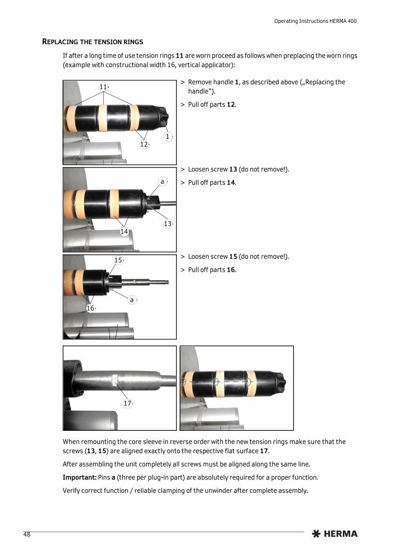
REPLACING THE TENSION RINGS
1
11
12
If after a long time of use tension rings 11 are worn proceed as follows when preplacing the worn rings (example with constructional width 16, vertical applicator):
> Remove handle 1, as described above („Replacing the handle“).
> Pull off parts 12.
1314
a
> Loosen screw 13 (do not remove!).
> Pull off parts 14.
16
15
a
> Loosen screw 15 (do not remove!).
> Pull off parts 16.
17
When remounting the core sleeve in reverse order with the new tension rings make sure that the screws (13, 15) are aligned exactly onto the respective flat surface 17.
After assembling the unit completely all screws must be aligned along the same line.
Important: Pins a (three per plug-in part) are absolutely required for a proper function.
Verify correct function / reliable clamping of the unwinder after complete assembly.
48

Operating Instructions HERMA 400
6.2.2 Motorized unwinder
INSERTING THE LABEL WEB
> If required, remove the counterholer (vertical mounting).
> Insert the label reel such that the labels reach the dispensing beak in the correct position. Use the suitable core sleeve.
> A: First guide the label web around the lower reversing roller 1 and then around pendulum 2 to the following sub-assembly (here: basic unit with label web brake). Depending on the situation further deflection of the web may be required (e.g. 3, fig. B).
i Due to the versatility of the winder system its components can be arranged differently – depending on where to mount them. For this reason the label web path can slightly vary. Therefore you will find the most common arrangements on pages 20 and 21.
If using the core sleeve with tension rings take note of the explanations in section 6.2.1 as of page 45.
A2
1
B
3
49

Operating Instructions HERMA 400
CHANGING THE CORE SLEEVE
For the use of label reels with different core diameters suitable core sleeves can be ordered as per the spare parts list.
> Remove counterholder. To do this, loosen clamping lever 4 and pull off the holder (fig. C).
> Remove the disk with core sleeve after loosening screw 5 (fig. D).
> Loosen three screws on the back of the disk (fig. E) and change core sleeve.
> On mounting the disk with core sleeve make sure that the screw 5 is aligned with the flat surface 6 (fig. F)
CHANGING THE SENSE OF ROTATION
> G: If the label winding changes (from outside to inside winding, or vice versa), the sense of rotation of the unwinder must be changed as well, via jumper 11 („X3“) on the circuit board 10.
With some configurations the sense of rotation can be changed with a toggle switch at the outside of the unwinder’s housing.
CHANGING THE SPEED
> G/H: The speed of the unwinder can be changed each via potentiometer 12 on the corresponding circuit board 10.
> A rule of thumb is: for an optimum labelling result choose the speed of the unwinder as high as needed, but as low as possible. The maximum speed required should be set with a minimum reel diameter (near the core diameter) and a pendulum that is swung out far. Adjust the speed of the transport roller of the loop unit (if any) correspondingly thereafter. See page 53.
C4
D5
E F6
G
12 11
H 10
i
50

Operating Instructions HERMA 400
6.2.3 Loop-type unwinder
SWITCHING OFF THE LOOP UNIT
>
!I: If the sensor for the loop control is free, that means e.g. no label web is inserted, the drive of the transport roller is set to „permanent run“! You can switch off the drive with the help of toggle switch 7 at the side of the housing. If this switch is missing, the loop control is managed by a superordinate control..
I
7
51

Operating Instructions HERMA 400
INSERTING THE LABEL WEB
> J: Guide the label web from the second reversing roller 8 to the transport roller 9 and around this (lift pressing roller). Create a loop with the label web and guide the web out of this unit to the following sub-assembly (basic unit with label web brake). Depending on the situation further deflection of the web may be required (e.g. 10, fig. I).
ALIGNING THE LOOP UNIT
> L, M: When mounted vertically the loop unit should be aligned such that the loop shaft is vertical, too. If required, the unit 14 is to be turned: Loosen screws 9 on both sides, turn the entire unit 14 and fix this new position with scews 9.
i Due to the versatility of the winder system its components can be arranged differently – depending on where to mount them. For this reason the label web path can slightly vary. Therefore you will find the most common arrangements on pages 20 and 21.
J 9
8
K
10
L
9
M14
52

Operating Instructions HERMA 400
CHANGING THE SPEED
> N, O: The speed of the loop-type unwinder can be changed via potentiometer 12 on the circuit board 10.
The speed of the transport roller of the loop unit ist to be adapted to the speed of the unwinder (if any). See page 50.
ADJUSTING THE LOOP CONTROL
> If the label material changes (e.g. transparent labels) the sensor 13 for the loop control may need adjustment. For further information see the separate manual of the sensor.
N
12
O
10
P
13
53

Operating Instructions HERMA 400
6.2.4 Label web brake
INSERTING THE LABEL WEB
> A: Push brake plate towards direction a to disengage it and at the same time towards direction b to loosen it (B).
> C: Pass label web below brake plate. Push brake plate towards direction c and depress until brake plate engages.
ADJUSTING THE BRAKING PRESSURE
Braking pressure was factory set. Adjust if required as follows:
> D/E: Loosen screw 1. Turn adjusting plate 2 to the left or to the right until label web passes below the brake plate smoothly, but with perceptible resistance. Tighten screw 1.
A
a
b
B C
c
D
1
2
E
1
2
54

Operating Instructions HERMA 400
CLEANING
> F: Push brake plate towards direction a to disengage it and at the same time towards direction b to loosen and fully retract it (G-I). Clean brake plate. After cleaning push brake plate back to position and depress until it engages.
F
a
b
G H
I
55

Operating Instructions HERMA 400
6.2.5 Label sensor FS01
CROSS ADJUSTMENT
> Slightly lift sensor 5 at the front and slide into the desired position.
SWITCH POINT ADJUSTMENT (only if sensor is built in)
> Position the pink ridge 1 of the sensor on the backing paper between two labels.
> Turn potentiometer 2 clockwise to the limit.(680295*: turn counterclockwise.)
> Turn it counterclockwise slowly thererafter until LED 3 goes out. (680295*: turn clockwise.)
> Then turn potentiometer further approx. 20° (one graduation mark).
* for electrically conductive labels (metallized or aluminium-covered)
56

Operating Instructions HERMA 400
BASIC ADJUSTMENT
This unit is factory set; required only if adjustment range is insufficient.For adjustment turn potentiometer 2 to middle position, open upper snap cover of sensing unit and adjust with the second potentiometer as described on the previous page.
POSITIONING THE LABEL
Direction of web movement
Depending on the application labels have to be peeled off completely (for suction), or a small part of the label remains attached to the backing paper (for tearing off, i.e. the product „takes“ the label), or a small part of the label is peeled off and most of it remains attached to the backing paper (for labelling with synchronous parallel motion).You can adjust the position of the label at the dispensing plate (label attachment) by positioning the sensing unit by means of holder 4 in or opposite to the direction of the label movement.
This positioning is also called „label overfeed delay“ or „stop delay“. With some configurations this delay is set via potentiometer at the applicator housing (see also section 5.1.1.2 / page 27) or in the control box or even via parameter in the control program (where applicable).
The order number of the sensor with plug-in connector is printed on the housing.
REPLACING THE SENSING HEAD
Sensing head 1 can be replaced after loosening screw 2.
Basic adjustment may be required to be repeated thereafter (see BASIC ADJUSTMENT).
Important: When using the label sensor HERMA-FS01 only sensors with material no. 680290 for non-metallised labels or no. 680295 for metallised labels may be used.
!
2
1
2 1
57

Operating Instructions HERMA 400
6.2.6 Label sensor optoelectronic
CROSS ADJUSTMENT
Scanning spot
> Loosen knurled nut 8.
> Move scanning spot of photoelectric cell 1 (see locating mark) over passing label web.
> In case of round labels the scanning spot should be positioned over the label centerline.
SWITCH POINT ADJUSTMENT (SENSOR WITHOUT TEACH FUNCTION)
> Turn adjusting screw 3 counterclockwise until light-emitting diode 4 goes out. (without backing paper)
> Pass backing paper through slot of photoelectric cell 1.
> Turn adjusting screw 3 clockwise until light-emitting diode lights up.
> Turn on one more circle.
SWITCH POINT ADJUSTMENT (SENSOR WITH TEACH FUNCTION)
2
1
> Position sensor on label.
> Press button 1 for at least 2 seconds. LED 2 flashes quickly. the teaching time is started.
> During this time move the label web for a length of at least two labels.
> The teach procedure is completed successfully if LED 2 flashes 2x. If LED2 flashes 4x we recommend to repeat the teaching procedure.
58

Operating Instructions HERMA 400
POSITIONING THE LABEL
Direction of web movement
Depending on the application labels have to be peeled off completely (for suction), or a small part of the label remains attached to the backing paper (for tearing off, i.e. the product „takes“ the label), or a small part of the label is peeled off and most of it remains attached to the backing paper (for labelling with synchronous parallel motion).By changing the position of the label scanning unit the amount of label left on the backing paper can be adjusted.
This positioning is also called „label overfeed delay“ or „stop delay“. With some configurations this delay is set via potentiometer at the applicator housing (see also section 5.1.1.2 / page 27) or in the control box or even via parameter in the control program (where applicable).
For normal/coarse adjustment
> Loosen locking screw 9.
> Move the entire scanning unit to the desired position.
> Carry out a test run.
> Tighten locking screw 9 thereafter.
For vernier adjustment
> Move the entire scanning unit to the desired position by means of adjusting wheel 10.
59

Operating Instructions HERMA 400
6.2.7 Dispensing systems
6.2.7.1 Rigid/Straight dispensing plates
Dispensing plate straight Dispensing plate straight, Dispensing plate, 75° angular with application roller
ADJUSTING THE DISPENSING PLATE
> Adjust paper guide 3 such that the label web sits close to screw head 4 and paper guide 3. With the dispensing plate with application roller make sure the distance between application roller and dispensing plate is less than one label length
i Explanations / Illustrations for threading the label web you will find in chapter 4.
i Correct label web tracking, if any, by adjusting the plate within the play of the mounting holes of screws 4 and 5 (see arrow).
60

Operating Instructions HERMA 400
6.2.7.2 Dispensing plate, 15° angular
INSERTING THE LABEL WEB
> Pull snaplock 1. Fold up holding-down plate 2.
> Pass label web below guide roller 3 and holding-down plate 2. Run backing paper back around the dispensing plate 4 and guide roller 5.
> Make sure the label web is in contact with screw head 6.
ADJUSTING THE DISPENSING PLATE
> Move paper guide 7 against the label web.
> Correct label web tracking, if any, by loosening screws 6 and 8 and adjusting the dispensing plate as desired.
ADJUSTING THE HOLD-DOWN PRESSURE
> Loosen screw 9.
> Turn holding-down plate 2 down (+) or up (–) until label web passes below the braking plate smoothly but with perceptible resistance.
> Tighten screw 9.
61

Operating Instructions HERMA 400
6.2.7.3 Pivot beak / Application unit
Pivot beak Application unit
ADJUSTING THE PIVOT BEAK / THE APPLICATION UNIT
12
7 5
64
3
57
6
> Adjust paper guide 1 such that the label web sits close to screw head 2 and paper guide 1.
> The distance between application roller 3 and dispensing plate 4 must be smaller than the length of one label. Adjust by loosening the four screws 5 and moving arms 6 in the elongated hole 7.
CLEANING
> Remove the guide roller 2 plus axle in the direction of the arrow and clean..
62

Operating Instructions HERMA 400
6.2.7.4 Moving beak
INSERTING THE LABEL WEB
3
4
1
2
> Pass the label tape around guide roller 1, towards the dispensing plate 2 and around the front edge. Run it back to the idling guide roller 3 (before going on, remove all unused labels from the backing paper from point 2 onwards). Pass the backing paper around roller 3, pull it forward again to and around the fixed guide roller 4, and run it back out again.
ADJUSTING FOR STRAIGHT LABEL WEB MOVEMENT
6
5
> When inserting the label tape, make sure it always nearly touches the housing with one side on its way through the moving beak. Loosen screw 5 and adjust the paper guide 6 such that it keeps the tape in place from the other side. Tighten screw 5.
CLEANING
> For cleaning simply pull the guide rollers off the axles. When placing them back onto the axles, make sure to shove them past the point of resistance to make them sit on the axles tightly.
Adjust the correct position (i.e. to what extent the label is to be peeled off the backing paper when dispensed) according to the description „Positioning the label“ in section 6.2.5 / 6.2.6 (page 57 / 59).
Caution: Pneumatic working pressure must not exceed 5 bar. Danger of crushing!!
63

Operating Instructions HERMA 400
64
6.2.8 Transfer systems
6.2.8.1 Telescope
POSITIONING THE LABEL ON THE SUCTION PLATE
POSITIONING THE TELESCOPE
X
Y
Suction plate
Label web / Dispensing beak
Set clearance (x) between suction plate and dispensing plate to approx. 1 mm; set clearance (y) between suction plate and label surface to approx. 1/10 to 2/10 mm (see illustration below).
Adjustments are made – depending on the version used – by means of spindles (with or without hand cranks).
i One of several possible telescopes (linear units) may be used in your machine, depending on the application. These units are maintenance-free. Take notice of the following:
Caution: Pneumatic working pressure must not exceed 5 bar. Danger of crushing!!
i Labels have to be centered on the suction plate.

Operating Instructions HERMA 400
65
6.2.9 Drive/Transport roller
INSERTING THE BACKING PAPER
> Push the lever with the handle 1 in the direction of the arrow (+).
> Overcome the resistance felt until pressure roller 2 is free.
> Pass the backing paper between the feed roller 3 and pressure roller 2 and place against the wall of the housing.
> Swing lever in arrow direction (-) as far as possible; you will hear the pressure roller engage..
ADJUSTING THE CONTACT PRESSURE
A> Adjust contact pressure such that the backing paper
is firmly held between feed roller 3 and pressure roller 2.
> To do this loosen screw 4 in the stop 1, adjust the contact pressure and firmly tighten the screw again.
> With wide backing paper slide pressure roller 2 on the axle to the center of the web
CLEANING
> A: Loosen screw in stop 4. Feed unit becomes disengaged. Clean pressure roller 2 and feed roller 3. After reassembling readjust the contact pressure.
Caution: Do not reach into the area where the feed roller draws in the web when machine is on!
U.K. only: Do not remove the nip roller guard.!
i The contact pressure is determined by the position of the stop 1. If pressure roller 2 only slightly runs past the dead center of the feed roller 3 this results in a high contact pressure; if the distance of movement is longer, contact pressure is lower.

Operating Instructions HERMA 400
6.2.10 Backing paper take-up unit standard
INSERTING THE BACKING PAPER
1
2
3
5
> Turn handle 1 completely to the left (maximum of five steps) to unclamp the unit.
> Run backing paper around bar 2.
> Run backing paper around the take-up roll and insert into slit 3. The backing paper should be inserted on a length of approx. 8 cm / 3“ at least. Correct direction is indicated with arrows 4.
> Turn handle 1 completely to the right (maximum of five steps) to make sure the backing paper is clamped with the highest possible force. This is required to ensure easy removal of the wound-up backing paper.
> Tighten the web by turning take-up roll 5.
4
66

Operating Instructions HERMA 400
BASIC ADJUSTMENT OF THE LEVER
14
If after a very long time of use rewinding does not function reliably anymore proceed as follows when effecting the basic adjustment:
> Remove take-up roll (roll including disc) after loosening screw 14.
23
19
> Unhook spring 23.
> Loosen screw 19 and clamping screw 18 (do not remove!).
21
2022
> Deflect lever 20 up to bolt 21 (where the spring is hooked onto).
22
19
> Turn sleeve 22 until lever 20 axially sits close to the housing.
> Put on screw 19.
> Verify that lever 20 can be moved freely in the entire swivel range. If required correct the axial position of the lever (position a little more in the opposite direction, i.e. with a slightly greater distance to the housing).
> Hook on spring 23.
18
17
67

Operating Instructions HERMA 400
20
> Deflect lever 20 widely. Tighten clamping screw 18 slightly (not completely) such that the lever remains deflected after letting go but still can be turned manually. Make sure at the same time that clamping piece 17 is fixed on the shaft without play.
18
17
20
> Position lever 20 manually into a position of approx. 80° – 85° with respect to the basic unit. Put on clamping screw 18 completely.
If you deflect and let go of the lever several times after having adjusted it this way it must stand still when guided back (not letting go from a deflected position) at a position of max. 90°.
68

Operating Instructions HERMA 400
REPLACING THE HANDLE
1
If after a very long time of use clamping of the backing paper with handle 1 does not function properly anymore proceed as follows when preplacing a worn handle:
> Turn handle 1 completely to the left (maximum of five steps) to unclamp the unit and make screw 10 accessible. Loosen screw 10 (do not remove!), retract the handle, insert new handle and fasten screw 10 afterwards.
REPLACING THE TENSION RINGS
2
12
If after a very long time of use tension rings 11 are worn proceed as follows when preplacing the worn rings (example with constructional width 24):
> Remove sleeve 2 after removing screw 12.
13
1
11
15
> Remove handle 1 as described above („Replacing the handle“).
> Pull off parts 13.
10
69

Operating Instructions HERMA 400
14
3
> Remove sleeve 3 after removing screw 14.
> Pull off remaining parts.
15
a
11
16
b
17
When remounting the core sleeve in reverse order with the new tension rings make sure that the screws (12, 14) together with the plug-in parts 15 (with pins) are aligned exactly onto the respective holes 16.
Moreover, screw 14 (the one closer to the disc) must be aligned exactly onto flat surface b on clamping piece 17.
After assembling the unit completely the screws (12, 14) must be flush with the sleeves.
Important: Pins a (three per plug-in part) are absolutely required for a proper function.
Verify correct function / reliable clamping of the rewinder after complete assembly.
70

Operating Instructions HERMA 400
6.2.11 Backing paper take-up unit motorized
SWITCHING THE UNIT OFF
>
!Without the web inserted the drive is set to „permanent run“. You can switch off the drive with the help of toggle switch 5 at the side of the housing.
INSERTING THE BACKING PAPER
> Switch off the drive.> Remove clip 1.> Run web around roll 3 of the pendulum 4.> Run web around take-up roll 2.> Replace clip 1 and clamp web.> Switch on the drive; the web will thus be tightened.
5
71

Operating Instructions HERMA 400
ADJUSTING THE SPEED
> The speed of the motorized backing paper take-up unit can be changed via potentiometer 12 on the circuit board 10. A change of speed is required only if the labelling performance changes substantially, or if the unit rewinds too slowly an thus undefined loops are created – when the winding diameter is low.
12
10
72

7 Troubleshooting
7.1 Indication of malfunctions
With H400 applicators the type of malfunction is indicated via the display (see section 7.1.1). Also, the LEDs of the key pad will give an indication (see section 7.1.2 „Malfunction table (LED indication)“).
ACKNOWLEDGING MALFUNCTIONS
i
If the applicator is connected to a superordinate control malfunctions very often are acknowledged centrally (e.g. at a touch display).1
Directly at the applicator or via superordinate control malfunctions are acknowledged by pressing the key or applying a signal (rising edge only ). See the following table (section 7.1.2, column „Acknowledge“).
Note: Always dispense at least two labels (pressing the key ) after occurrence of a malfunction in order to ensure a correct label‘s position at the dispensing beak. If there are optional print or control systems present and active, as many labels must be dispensed as there are between dispensing beak and the remotest unit.
1. If pin X10.12 available
0
1
73
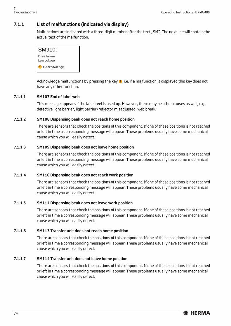
7 TROUBLESHOOTING Operating Instructions HERMA 400
7.1.1 List of malfunctions (indicated via display)
Malfunctions are indicated with a three-digit number after the text „SM“. The next line will contain the actual text of the malfunction.
Acknowledge malfunctions by pressing the key , i.e. if a malfunction is displayed this key does not have any other function.
7.1.1.1 SM107 End of label web
This message appears if the label reel is used up. However, there may be other causes as well, e.g. defective light barrier, light barrier/reflector misadjusted, web break.
7.1.1.2 SM108 Dispensing beak does not reach home position
There are sensors that check the positions of this component. If one of these positions is not reached or left in time a corresponding message will appear. These problems usually have some mechanical cause which you will easily detect.
7.1.1.3 SM109 Dispensing beak does not leave home position
There are sensors that check the positions of this component. If one of these positions is not reached or left in time a corresponding message will appear. These problems usually have some mechanical cause which you will easily detect.
7.1.1.4 SM110 Dispensing beak does not reach work position
There are sensors that check the positions of this component. If one of these positions is not reached or left in time a corresponding message will appear. These problems usually have some mechanical cause which you will easily detect.
7.1.1.5 SM111 Dispensing beak does not leave work position
There are sensors that check the positions of this component. If one of these positions is not reached or left in time a corresponding message will appear. These problems usually have some mechanical cause which you will easily detect.
7.1.1.6 SM113 Transfer unit does not reach home position
There are sensors that check the positions of this component. If one of these positions is not reached or left in time a corresponding message will appear. These problems usually have some mechanical cause which you will easily detect.
7.1.1.7 SM114 Transfer unit does not leave home position
There are sensors that check the positions of this component. If one of these positions is not reached or left in time a corresponding message will appear. These problems usually have some mechanical cause which you will easily detect.
SM910: Drive failureLow voltage
= Acknowledge
74

7 Operating Instructions HERMA 400 TROUBLESHOOTING
7.1.1.8 SM115 Transfer unit does not reach work position
There are sensors that check the positions of this component. If one of these positions is not reached or left in time a corresponding message will appear. These problems usually have some mechanical cause which you will easily detect.
7.1.1.9 SM116 Transfer unit does not leave work position
There are sensors that check the positions of this component. If one of these positions is not reached or left in time a corresponding message will appear. These problems usually have some mechanical cause which you will easily detect.
7.1.1.10 SM119 Label check Error after label feed
After dispensing a label there must be a label on the vacuum pad, detected by the integrated vacuum control. In this case the control unit does not detect a vacuum which means that probably there is no label on the pad. The reason for this may be a web break or a missing label on the web. Carry out a visual check.
7.1.1.11 SM120 Label check Error after label transfer
After transferring a label there must not be a label on the pad anymore, detected by the integrated vacuum control. In this case the control unit still detected a vacuum which means that probably there is still a label on the vacuum pad. Carry out a visual check to determine the cause. Maybe this is even a problem with the material to be labelled (the label could not stick to the product).
7.1.1.12 SM148 Missing label series fault (web break?)
This message appears if the label sensor could not detect a label three consecutive times (or as many times as set with the corresponding parameter (if any)). Check the sensor (setting) or your label material.
7.1.1.13 SM153 Multi labelling Start sequence too close
This message appears if with activated multi labelling (parameter 160) the various labels are too close to each other. You may have to increase the corresponding start delays.
7.1.1.14 SM164 Start signal Sensor mark not detected
This message appears if parameter 140 is set to „Sensor mark“ but this mark could not be detected within a certain time. Check adjustment of the mark reader.
7.1.1.15 SM165 Roller unit Communication error
This message appears if with using a subordinate basic unit, e.g. the roller motor of a type 211 labeller, a connection to this unit could not be established. Check the connection via X18 and be aware that this connection must be interrupted before updating the software or initializing the unit for the first time.
7.1.1.16 SM166 Applicator Communication error
This message appears if with using a superordinate basic unit, e.g. the applicator motor of a type 211 labeller, a connection to this unit could not be established. Check the connection via X18 and be aware that this connection must be interrupted before updating the software or initializing the unit for the first time.
7.1.1.17 SM167 Roller unit Error
This message appears if there is an error at the roller motor (roller prism, type 211). Maybe something is blocked. After remedying first acknowledge at the roller unit and then at the main unit.
75

7 TROUBLESHOOTING Operating Instructions HERMA 400
7.1.1.18 SM168 CAN connection Disconnect!
This message appears if the CAN connection must be interrupted/disconnected (at X18).
7.1.1.19 SM169 Firmware update required!
This message appears if you have to update the firmware (e.g. via the Config software) because the firmware of the CAN I/O and the firmware of the drive unit do not match, e.g. because one of the units was replaced.
7.1.1.20 SM181 Chip changed!
This message appears if the chip determining the applicator model was changed or not properly recognized during operation.
7.1.1.21 SM199 CAN communication no CAN module detected
This message appears if there is no connection to the required CAN module. Check the cabling.
7.1.1.22 SM910 Drive failure Low voltage
This message appears if low voltage was detected. Please turn to our Technical Service or to your HERMA partner if this malfunction occurs repeatedly.
7.1.1.23 SM911 Drive failure High voltage
This message appears if high voltage was detected. Please turn to our Technical Service or to your HERMA partner if this malfunction occurs repeatedly.
7.1.1.24 SM912 Drive failure High temperature
This message appears if a high temperature was detected. Please turn to our Technical Service or to your HERMA partner if this malfunction occurs repeatedly.
7.1.1.25 SM913 Drive failure Overload (period)
This message appears if the peak current was required for more than 3 seconds. Please turn to our Technical Service or to your HERMA partner if this malfunction occurs repeatedly.
7.1.1.26 SM914 Drive failure
This message appears if the encoder signals of the applicator drive could not be used. Please turn to our Technical Service or to your HERMA partner if this malfunction occurs repeatedly.
7.1.1.27 SM917 Drive failure Powerfail
This message appears if power supply of the intermediate circuit falls below a critical point. Please turn to our Technical Service or to your HERMA partner if this malfunction occurs repeatedly.
7.1.1.28 SM918 Drive failure
This message appears if during initialization a connection to the motor encoder could not be established. Please turn to our Technical Service or to your HERMA partner if this malfunction occurs repeatedly.
7.1.1.29 SM919 Drive failure Low voltage (peak)
This message appears if there is s short low voltage in the intermiediate circuit. Please turn to our Technical Service or to your HERMA partner if this malfunction occurs repeatedly.
76

7 Operating Instructions HERMA 400 TROUBLESHOOTING
7.1.1.30 SM920 Drive failure Overload (peak)
This message appears if the maximum peak current was exceeded. Please turn to our Technical Service or to your HERMA partner if this malfunction occurs repeatedly.
7.1.1.31 SM921 Drive failure
This message appears if during initialization transistors could not be addressed. Please turn to our Technical Service or to your HERMA partner if this malfunction occurs repeatedly.
7.1.1.32 SM922 Drive failure
This message appears if the reference voltage is beyond specification. Please turn to our Technical Service or to your HERMA partner if this malfunction occurs repeatedly.
7.1.1.33 SM923 Drive failure
This message appears if there is a high discrepancy between nominal and current position. May indicate an overload. Please turn to our Technical Service or to your HERMA partner if this malfunction occurs repeatedly.
7.1.1.34 SM924 Drive failure Overload
This message appears if there is a drive failure with following switching off the PWM amplifier. Please turn to our Technical Service or to your HERMA partner if this malfunction occurs repeatedly.
7.1.1.35 SM925 CAN communication disturbed
This message appears if there is a failure in the connection to the CAN I/O board. Please turn to our Technical Service or to your HERMA partner if this malfunction occurs repeatedly.
77

7 TROUBLESHOOTING Operating Instructions HERMA 400
7.1.2 Malfunction table (LED indication)
• Function possible (press key, apply signal (rising edge only 0
1, i.e. level change from low to high))
o Function impossible — without function
LED Acknowledge
Malfunction ON (ext.)
Feed (ext.)
Reset (ext.)
Clamping lever open (nip roller), web break, or missing stop signal (label sensor) – without printer 1
2x 2x • • • • o •
Clamping lever open (nip roller), web break, or missing stop signal (label sensor) – with printer 1
3x 3x • • • • o •
Diminishing reel at reel holder — — — — — — — —
End of reel at reel holder, without lock (stop automatic mode)
— — — — — — — —
End of reel at reel holder, with lock (stop automatic mode)
4x 4x • • • • o •
Type difference of applicator chip during operation 2
5x 5x • • • • o •
Overload switching outputs (CAN I/O) 3 6x 6x • • • • o •
Products follow too close to each other 8x 8x • • • • o •
Voltage too low 3 — 10x • • • • o •
Voltage too high (brake energy) 3, 4 — 11x • • • • o •
Overload 1 3 — 12x • • • • o •
Overload 2 3, 5 — 13x • • • • o •
Motor blocking protection 3 — 14x • • • • o •
System error 3 — 15x • • • • o •
Overload 3 3 — 16x • • • • o •
78

7 Operating Instructions HERMA 400 TROUBLESHOOTING
7.1.2.1 Remedy of malfunctions
• Close lever at the drive roller (nip roller) (see also fig. on page 26).
• Check label web, insert if required.
• Check label sensor (stop signal), replace if required.
• Use only the correct chip belonging to the applicator
• Please turn to our Technical Service or to your HERMA partner if a malfunction occurs repeatedly.
• Check voltage.
• Remove any label remainders from the drive/transport roller.
7.1.3 Error blink codes with PLC connection
Reset
If the applicator is used with a PLC control without operator panel usually blink codes are implemented (usually the reset button blinks. For acknowledging the error press the reset button then).
Frequent blink codes are, e.g.:.
The blink codes that are actually used in your applicator you will find in the PLC overview page of the wiring diagram.
Malfunction type Remedy
1
2
3
4
5
1x Malfunction drive
2x Dispensing timeout
3x Dispensing beak does not reach or leave its home position mechanical problem or problem with sensor)
4x Labelling cycle timeout
5x Transfer unit does not reach or leave its home position (mechanical problem or problem with sensor)
6x End of reel
7x Malfunction printer
79

7 TROUBLESHOOTING Operating Instructions HERMA 400
7.2 Other malfunctions
On the following pages you will find a table with possible malfunctions that you can correct by yourself. In case of malfunctions or defects that you cannot correct please contact our Technical Service (see section 7.4).
Malfunction Cause Remedy
Labeller does not start up a) No supply voltage. a) Connect labeller up to mains.
b) Labeller not switched on. b) Switch on main switch at control box and push-but-ton at labeller housing.
c) Plug connections loose. c) Check plug connections and make sure coupling rings are screwed on tightly.
d) Drive defective. d) Replace drive. (section 7.3)
Labeller does not dispense label
a) Label web inserted incor-rectly.
a) Insert label web according to description for the rele-vant component (chapters 4 and 6 ).
b) Pressure roller disengaged. b) Engage pressure roller (section 6.2.9, „Inserting the backing paper“)
c) Toothed belt defective.. c) Replace toothed belt.
Label web passes through continuously
a) Label sensing/scanning misadjusted.
a) Readjust switch point (section 6.2.5 / 6.2.6).
b) Label sensing/scanning unit defective.
b) Replace label sensing/scanning unit.
c) Label sensing/scanning unit dirty.
c) Clean label sensing/scan-ning unit (chapter 8).
d) Too little space between labels.
d) Choose lower label web speed.
80

7 Operating Instructions HERMA 400 TROUBLESHOOTING
Label web tears a) Backing paper punched. a) Reduce backing paper ten-sion, reduce pressure of label-web brake (section 6.2.4).
b) Label remainders clamped beneath sensing/scanning unit.
b) Clean sensing/scanning unit (chapter 8).
c) Paper guide too close to the label.
c) Adjust paper guide for width of label web.
d) Label web inserted incor-rectly.
d) Insert label web according to description of relevant component (chapters 4 and 6).
e) Label web tracking. e) Adjust dispensing system (section 6.2.7).
Backing paper is not wound up a) Friction clutch in the drive is worn out.
a) Let our service staff exchange the friction clutch.
b) Drive belt torn. b) Replace drive belt of backing paper take-up unit.
Labels are placed inaccurately a) Product sensing inaccurate or defective.
a) Check and correct the product sensor.
b) Label sensing/scanning unit loose or defective.
b) Fasten or replace and adjust the label sensor (section 6.2.5 / 6.2.6)
c) Pressure roller misadju-sted, backing paper slips.
c) Correctly adjust pressure roller (section 6.2.9).
d) Irregular distances bet-ween labels on backing paper .
d) Check for regular distances between labels on label web, in case of irregular distances use new label roll.
Malfunction Cause Remedy
81

7 TROUBLESHOOTING Operating Instructions HERMA 400
7.3 Replace the drive unit
7.3.1 Remove the drive unit
For removing the drive unit proceed as follows:
❏ Make sure the applicator is voltage-free and the mains plug is disconnected.
❏ Loosen the large hexagon bolt of the pedestal mounting.
❏ Retract the applicator housing on the rail to the front until the back of the applicator housing can be opened.
❏ Open the back of the applicator housing (three screws).
Drive unit Applicator housing
Hexagon boltfor pedestal mounting
ATTENTION!Do not open these screws! See the note on page 13.
Warning: Before opening the applicator housing disconnect mains plug!!
82

7 Operating Instructions HERMA 400 TROUBLESHOOTING
BACK OF THE APPLICATOR HOUSING
❏ Loosen the motor cables (mains plug (pin1+3) 1, protective earth conductor 2 and 34channel control cable 3).
❏ Remove the distributor circuit board 4.
❏ Loosen three screws 5 and remove the toothed-belt tensioner 6.
❏ Loosen four motor screws 7 and remove the drive unit 8. Carefully guide the cables through the cable feed-throughs 9.
1
2
3
56
4
78
9
8
83

7 TROUBLESHOOTING Operating Instructions HERMA 400
7.3.2 Ship the drive unit
❏ Secure the motor with the help of at least one screw (M4) in the housing of the drive unit.
❏ Make sure to pack the drive unit such that it is non-slip and well padded.
❏ Send the drive unit to be replaced to the Technical Service of HERMA GmbH with giving the reason for return. The address you will find in section 7.4.
7.3.3 Mount the drive unit
As the case may be, firstly remove the transport lock of the drive unit.
For mounting the drive unit fasten all components that were loosened, as described in section „7.3.1 Remove the drive unit“, with proceeding in reverse order.
7.4 Technical Service
Central office
Technical Service HERMA GmbH Plochinger Straße 48 73779 Deizisau / Germany Telephone +49 (0)711 7702 551
Drive unit
Transport lock!
84

8 Cleaning and maintenance
CLEANING NOTES
Some more notes on cleaning you will find in the respective description of the sub-assemblies (sections 6.2).
EXCHANGING FUSES
> Use suitable gripping tool for removing and inserting.
See chapter 9 for fuse specifications.
Warning: Before carrying out cleaning or maintenance work disconnect machine from mains!!
i • Use cleaning material only that does not attack metal, rubber, or plastics parts.
• Make sure that all machine parts that touch the products to be labelled are free from adhesive or label fragments.
• Remove adhesive residue with a label solvent.
• Clean label sensing/scanning unit with a soft cloth only.
• Do not remove adhesive residue from reversing and feed rollers with sharp-edged objects.
Warning: Before opening control box or labeller housing, disconnect from mains! When cutting the HERMA 400 applicator off mains you must wait for at least five minutes before opening the housing or touching connector pins. RESIDUAL VOLTAGES!
!
97915
WARRANTY
Important: Opening the screws at the front of the drive unit will void the warranty! i
85

8 CLEANING AND MAINTENANCE Operating Instructions HERMA 400
Label l ing Systems
www.herma.com [email protected]
86

9 Technical Data
HERMA 400 labellers are factory-tested prior to shipment and ready to operate. They come with basic adjustments.The following specifications refer to the applicator’s drive unit.
Power supply / Line voltage Wide range input 100V AC ... 240V AC ±10%, 50 Hz ... 60 Hz
Max. power consumption approx. 400 VA
Leakage current, according to EN 60335-1 110VAC: <0.35 mA 150VAC: <0.5 mA 230VAC: <0.7 mA
Fuse protection in the applicator 2x T 3.15 A type TR5
Operating temperature range +0°C ... +40°C (+32°F ... 104°F)
Storage and transport temperature -20°C ... +80°C (-4°F ... 176°F)
Maximum installation elevation with nominal data 2.500 m above mean sea level
Maximum permissable relative humidity 35% ... 85%, free of condensation
Sound pressure level in operation at working place according to DIN 45635
max. 75dB(A)
Type of protection IP54
Output capability 250 mA (nominal), short circuit-proof, = maximum load over all outputs
Safety class Class 2 peripherals may be connected
Diameter label reel Standard: 300 mm (12“) Maximum: 400 mm (16“, optional)
Core diameter Standard: 76 mm (3“)
Constructionial variants For right-hand and left-hand operation
Dimensions Customer-specific
! Warning! This device may cause radio interference in residential areas; in such case the operating company may be obliged to take appropriate measures.
87

9 TECHNICAL DATA Operating Instructions HERMA 400
Further applicator data you can find on the type label on the cover of this manual.
i Under extreme operational conditions, maybe e.g. with model H400 Premium, above-mentioned ranges are subject to restrictions that cannot be defined exactly. In case of an overload the applicator may switch off automatically.
88

9 Operating Instructions HERMA 400 TECHNICAL DATA
When connecting the applicator to an external control there are connectors available for inputs and outputs. For the assignment of these optional connectors see the following sections.
9.1 Inputs / outputs (X10) (option, standard signals)
This optional connector provides inputs/outputs to the external control (e.g. PLC).
† Note: Functionality active only if jumper „Remote“ (see wiring diagram) is set.
X10 Designation I/O Description Color ➜97900
PIN
1 LED3 OUT LED function key (printer status) brown X22.8
2 GND I/O Ground (all voltages DC) blue X22.2
3 READY OUT Applicator ready white X22.4
4 END OUT End of reel green X22.7
5 DIM OUT Diminishing reel pink X22.5
6 ON† IN Applicator ON (1-active) yellow X22.3
7 FAULT OUT Error applicator (incl. web break) black X22.6
8 STOPDELAY* IN 0-10V stop delay grey X23.4
9 ADC+10V OUT +10V DC for analog inputs red X23.1
10 SPEED IN 0-10V speed violet X23.3
11 STARTDELAY* IN 0-10V start delay greypink X23.5
12 ACK IN Reset error redblue X22.1
89

9 TECHNICAL DATA Operating Instructions HERMA 400
9.2 Inputs / outputs (X19) (option, extended signals)
This optional connector provides inputs/outputs to the external control (e.g. PLC).
** Note: Jumper „Feed“ is not set: Without control via PLC, Pin 12 and Pin 4 must be bridged in order to activate the function of the manual feed key. When using an external control the functionality of the manual feed key must be realised via a corresponding logic. Jumper „Feed“ is set: Manual feed is possible via the key as well as externally.
†† Note: START (6) possible only if LOCK (9) not active.
X19 Designation I/O Description Color ➜97900
PIN
1 +24V OUT Power supply (<150mA) brown X31.9
2 GND I/O Ground (all voltages DC) blue X31.2
3 M_ENC_A IN Master encoder track A white X30.2
4 FEED** IN Manual feed green X31.5
5 STOP OUT Label sensor (end of transport) pink X31.4
6 START†† IN Start of labelling yellow X21.4
7 M_ENC_B IN Master encoder track B black X30.4
8 S3 OUT Key S3 „function“ grey X31.6
9 LOCK†† IN Lock labelling start (1-active) red X31.10
10 NO_LABEL OUT Missing label on web violet X31.7
11 ACTIVE OUT Label transport running greypink X31.3
12 S2** OUT Key S2 „manual feed “ redblue X31.8
0
1
0
1
90

10 Declaration of Conformity / Manufacturer
HERMA GmbH Division Labelling Systems Plochinger Straße 48 73779 Deizisau / Germany
EC Declaration of Conformity / Manufactureraccording to the EC Machinery Directive 98/37/EG, appendix II A / B
EC EMC Directive 2004/108/ECEC Low-voltage Directive 2006/95/EEC
We hereby declare that the following machinery is developed, designed, and manufactured by us in our sole responsibility in compliance with above mentioned EC Directives. With any change of the machine which has not been settled with us this declaration looses its validity.
If integrated into another machine this machine must not be put into operation until it is established that the machinery into which this machine is to be integrated complies with the relevant requirements of the EC Machinery Directive.
Machine description: Labeller
Machine type: HERMA 400 (see type label)
Machine no.: (see type label)
Applied harmonized standards: EN 415-2 EN 60204-1
For evaluating the machinery regarding electromagnetic compatibility the following standards were used:
EN 61000-6-2:2005 EN 61000-6-4:2007
Date / Signature manufacturer: ______________
Date Technical manager
91

10 DECLARATION OF CONFORMITY / MANUFACTURER Operating Instructions HERMA 400
Label l ing Systems
www.herma.com [email protected]
92

93
11 Spare parts
ORDERING INSTRUCTIONS
> For processing of spare parts orders we absolutely need the material number (Mat.-No.).
> In order to avoid queries please state applicator number as well.
PROCEDURE
> Obtain the material number of the part needed with the help of its position no.
> For all parts that are available in different types obtain the type of your labeller from the type plate (width and constructional type) and, as the case may be, from the display (type). The type plate/label you will find on the side of the labeller housing and as well on the cover page of this manual.
Example: HERMA 400 L V 8
Construction: Left-hand L
Right-hand R
Type: Fix F
Vario V
Vario M VM
Premium P
PremiumPlus PPS
Backing paper width: Max.: 82 mm (3.3“) 8
Max.: 164 mm (6.5“) 16
Max.: 244 mm (9.6“) 24
Max.: 328 mm (13“) 32

Ersatzteile / Spare parts / Pièces de rechange
GRUNDEINHEIT BASIC UNIT UNITÉ DE BASE
5 18
17
21
19 20
15
8
7
6
32
4
9
1
12
13
b
16
7
14
22
Pos. Bezeichnung Ausf. Stck. Mat.-Nr.Item Description Design Pcs. Mat.-No.Pos. Désignation Version Nbre No.-mat.
1 Transportwalze komplett Transport roller complete Rouleau de transport complet ➀
16 16 16 ➁ 1 7000005524 24 24 ➁ 1 7000023032 32 32 ➁ 1 70000234
2 Schwenkhebel komplett Swivel lever complete Levier de blocage complet ➀ 1 6001323 Klemmstück komplett Clamp piece complete Pièce de serrage complet 1 6001384 Rolle komplett Roller complete Rouleau complet 1 6001345 Zahnriemen Toothed belt Couroie crantée ➀ 1 6119746 Bremsblech Brake plate Tôle-frein 1 6000257 Einstellblech Adjusting plate Tôle d’ajustage
L L L (gauche) 1 647448R R R (droite) 1 647449
8 Papierführung Paper guide Guide bande 1 6160239 H400 Antr.einheit kompl. H400 drive-unit complete Entraînement complet H400 ➀ 1 647430
inkl. Elektronik, ohne Gehäuse (b) incl. electronics, w/o housing (b) incl. electronics, sans boîtier (b) ➀
12 H400 CAN I/O Platine m. Dilsplay H400 CAN I/O circuit board w display Carte de circuits H400 CAN I/O /display 1 09794013 H400 Netzfilter-Platine H400 filter cilrcuit board Carte de circuits H400, filter 1 09791514 Folientastatur Display Foil keypad display Clavier à effleurement display 1 64742815 Folientastatur H400 Foil keypad H400 Clavier à effleurement H400 1 64741616 Riemenscheibe z14 komplett Pulley z14 complete Poulie z14 complet 1 64692817 Riemenscheibe Z32 Walze Pulley z32 roller Poulie z32 rouleau 1 64692618 Spannelement Tensioner Tendeur 1 61197719 Riemenscheibe Z14 Motor Pulley z14 motor Poulie z14 moteur 1 64692320 Scheibe komplett Disk complete Disque complet 1 64692921 Abziehwerkzeug für Pos.17+18 Pulling-off-device for pos.17+18 Démonte-roue pour pos.17+18 64694522 Kleinstsicherung 3,15 A Microfuse 3.15 A Petit coupe-circuit 3.15 A 2 617349
➀ Bei beabsichtigter Lagerhaltung empfohlen // Recommended if holding stocks is desired // Recommandé en cas de stockage prévu ➁ Bei Geräteschlüssel/ with type code/ avec type 201... 16 = 646940, 24 = 601145, 32 = 602584
GARANTIEWARRANTYGARANTIE
Wichtig: Durch das Öffnen der Schrauben an der Vorderseite der Antriebseinheit erlischt der Garantieanspruch!
Important: Opening the screws at the front of the drive unit will void the warranty!
Important: L’ouverture des vis sur la face avant de l’entraînement provoque la perte du droit à la garantie !i
94

Ersatzteile / Spare parts / Pièces de rechange
MOTORISCHER (SCHLAUFEN-)VORROLLER MOTORIZED (LOOP-TYPE) UNWINDER 1/2 DÉROULEUR À MOTEUR (DE BOUCLE)
1
2
3
5
4 11
10
6
712
9
8
Pos. Bezeichnung Ausf. Stck. Mat.-Nr.Item Description Design Pcs. Mat.-No.Pos. Désignation Version Nbre No.-mat.
1 Scheibe Disc Disqueø 404 mm ø 404 mm (16“) ø 404 mm ➀ 1 625258ø 404 mm ø 404 mm (16“) ø 404 mm 1 625153
2 Scheibe, komplett Ring, complete Disque, complet- für Hülse - for core - pour douilles
ø 40 mm ø 40 mm (1,6“) ø 40 mm 1 625357ø 50 mm ø 50 mm (2“) ø 50 mm 1 625358ø 70 mm ø 70 mm (2,75“) ø 70 mm 1 625359ø 76 mm (3“) ø 76 mm (3“) ø 76 mm (3“) 1 625360ø 90 mm ø 90 mm (3,5“) ø 90 mm 1 625361
3 Gegenhalter, komplett Counter holder, complete Contre support, completø 400 mm, stehend ø 400 mm, vertical ø 400 mm, verticale- für Hülse - for core - pour douilles
ø 40 mm ø 40 mm (1,6“) ø 40 mm 1 625326ø 50 mm ø 50 mm (2“) ø 50 mm 1 625327ø 70 mm ø 70 mm (2,75“) ø 70 mm 1 625328ø 76 mm (3“) ø 76 mm (3“) ø 76 mm (3“) 1 625329ø 90 mm ø 90 mm (3,5“) ø 90 mm 1 625330
ø 400 mm, liegend ø 400 mm, horizontal ø 400 mm, horizontale- für Hülse - for core - pour douilles
ø 40 mm ø 40 mm (1,6“) ø 40 mm 1 625365ø 50 mm ø 50 mm (2“) ø 50 mm 1 625364ø 70 mm ø 70 mm (2,75“) ø 70 mm 1 625363ø 76 mm (3“) ø 76 mm (3“) ø 76 mm (3“) 1 625362ø 90 mm ø 90 mm (3,5“) ø 90 mm 1 625366
4 Pendel, komplett Pendulum, complete Pendule, complet8 8 8 1 625302
5 Rolle, komplett Roller, complete Rouleau, complet8 8 8 1 620356
6 Welle, komplett Shaft, complete Arbre, complet24 24 24 1 625308
7 Bolzen Bolt Axe 1 0889378 Bolzen Bolt Axe 1 6253569 Scheibe Disc Disque 1 65575510 Zahnrad z59 Gear wheel z59 Roue dentée z59 1 62531911 Zahnrad komplett z21/43 Gear wheel complete z21/43 Roue dentée complet z21/43 1 62532112 Zugfeder Tension spring Ressort de traction 1 611951
➀ Nur Kerndurchmesser 40 mm / core diameter 40 mm (1,6“) only / seulement diamètre de la douille du rouleau 40 mm
95

Ersatzteile / Spare parts / Pièces de rechange
MOTORISCHER (SCHLAUFEN-)VORROLLER MOTORIZED (LOOP-TYPE) UNWINDER 2/2 DÉROULEUR À MOTEUR (DE BOUCLE)
114
15
13
16
17
22
19
18
21
11 10
20
Pos. Bezeichnung Ausf. Stck. Mat.-Nr.Item Description Design Pcs. Mat.-No.Pos. Désignation Version Nbre No.-mat.
13 Platine Circuit board Carte de circuits 1 09762014 Motor Motor Moteur 1 61583715 Blech Sheet metal Tôle 1 62532516 Schaltnetzteil Power pack switch Bloc d’alimentation 1 09754917 Variotronic Variotronic Variotronic 1 61583818 Reflexionslichtschranke Photoelectric reflex switch Barriére rèflex
inkl. Reflektor incl. reflector incl. reflecteur 1 61195719 Andrückrolle Pressure roller Rouleau de pression 1 60013220 Schenkelfeder Torsion spring Ressort à branches
für for pour ➀ 1 625426für for pour ➁ 1 625427
21 Walze Roller Rouleau8 8 8 1 62540816 16 16 † 2 625408†: + Schraube / screw / vis 1 610096
22 Schalter Switch Interrupteur 1 625367
➀ Andrückrolle rechts von Transportwalze / Pressure roller right of transport roller / Pressure roller right of transport roller➁ Andrückrolle links von Transportwalze / Pressure roller left of transport roller / Pressure roller left of transport roller
96

Ersatzteile / Spare parts / Pièces de rechange
STANDARD ABWICKLER STANDARD UNWINDER PORTE BOBINE
1 23
4 5
3
5
5 5
46 7
8
9
Pos. Bezeichnung Ausf. Stck. Mat.-Nr.Item Description Design Pcs. Mat.-No.Pos. Désignation Version Nbre No.-mat.
1 Gegenhalter Counter holder Contre-poulie Porte bobineø 300 mm ø 300 mm (12“) ø 300 mm 1 620415ø 400 mm ø 400 mm (16“) ø 400 mm 1 620416
2 Griff komplett Handle complete Poignée complet 1 6204323 Schwinge komplett Rocker complete Manivelle oscillante complet ➀ 1 6204564 Näherungsschalter Proximity switch Détecteur de proximité 1 0979315 Zugfeder 1,0x6,0x54,4 Tension spring 1.0x6.0x54.4 Ressort de traction 1,0x6,0x54,4 ➀ 1–4 6170216 Formteil-PU Mould-PU Préformé-PU ➀ 1 6204687 Formteil komplett Mould complete Préformé complet ➀ 1 6204338 Ring 74x23 Ring 74x23 Ring 74x23 ➀ 2–4 7766679 Stange 4x55 Bar 4x55 Barre 4x55 1 620447
➀ Bei beabsichtigter Lagerhaltung empfohlen // Recommended if holding stocks is desired // Recommandé en cas de stockage prévu
97

Ersatzteile / Spare parts / Pièces de rechange
ETIKETTENABTASTUNG FS01 LABEL SENSOR FS01 UNITÉ DE PALPAGE FS01
7425
6
1
3
Pos. Bezeichnung Ausf. Stck. Mat.-Nr.Item Description Design Pcs. Mat.-No.Pos. Désignation Version Nbre No.-mat.
1 Etikettenabtastung Label sensing Indexage d’étiquettesmit Steckverbinder with connector avec fiche
FS 01 FS 01 FS 01 ➁ 1 680290FS 01 FS 01 FS 01 ➁➃ 1 680295
2 Abtastkopf komplett Sensing head complete Tête de palpage, completFS 01 FS 01 FS 01 1 680258
3 Halter komplett Holder complete Support completR R R (droite) 1 646635L L L (gauche) 1 646636
4 Federndes Druckstück M4 Setscrew M4 Vis de guidage M4 ➂ 1 6466375 Kugel D5 Stahl Ball Bille 1 6115396 Druckfeder Pressure spring Ressort de traction 1 6115607 Anschlag Stop Butée 1 680268
➁ „High“ auf Etikett / „high“ on label / „high“ sur l’étiquette➂ Bei Feinverstellung / for vernier adjustment / pour réglage micrométrique➃ Für Metalletiketten / for metallic labels / pour étiquettes métallisées
98

Ersatzteile / Spare parts / Pièces de rechange
ETIKETTENABTASTUNG OPTOELEKTRONISCH LABEL SENSOR OPTOELECTRONIC UNITÉ DE PALPAGE PHOTOÉLECTRIQUE
7
4
1
3
2
5a 5b
6
1a
Pos. Bezeichnung Ausf. Stck. Mat.-Nr.Item Description Design Pcs. Mat.-No.Pos. Désignation Version Nbre No.-mat.
1 Lichtschranke Photocell Cellule GS06/66D-2... 1 097306 GS06/66-5 1 614903
1a Lichtschranke incl. Teach Photocell incl. Teach Cellule incl. Teach OGUTI 06205 1 0979332 Formteil, komplett Mould, complete Préformé, complet 1 6466313 Formteil Mould Préformé 1 6462264 Stift Pin Cheville 1 6462545a Zylinderschraube M4 x 10 Cheesehead screw M4 x 10 Vis à tête cylindrique M4 x 10 ➀ 1 6467635b Druckstück, federnd Thrust piece, elastique Membre de pression, élastique ➁ 1 6466376 Sicherungsscheibe Circlip Circlip 1 6107787 Rändelmutter M4 Knurled nut M4 Ecrou moleté bas 1 610543
➀ Für Normalverstellung/ for normal adjustment / pour réglage approximatif➁ Für Feinverstellung / for vernier adjustment / pour réglage micrométrique
99

Ersatzteile / Spare parts / Pièces de rechange
SCHWENKZUNGE / ANDRÜCKEINHEIT PIVOT BEAK / APPLICATION UNIT LANGUETTE PIVOTANTE / UNITÉ D’APPLICATION
4
3
2
1514
13
5 619
16
978
9
10
1211
18
17
20
1
Pos. Bezeichnung Ausf. Stck. Mat.-Nr.Item Description Design Pcs. Mat.-No.Pos. Désignation Version Nbre No.-mat.
1 Schwenkzunge, komplett Pivot beak complete Languette pivotante, completohne Walze without roller sans rouleau
8 8 8 1 69042016 16 16 1 690425
2 Andrückeinheit, komplett Application unit complete Unité d’application, completohne Walze without roller sans rouleau
8 8 8 1 69101016 16 16 1 691013
3 Näherungsschalter Proximity switch Détecteur de proximité ➁ 1 0972814 Zargenpuffer Buffer Amortisseur 1 6115985 Walze,Moosgummi Rubber roller Rouleau gommé
42 mm 42 mm (1,65“) 42 mm 1 09169883 mm 83 mm (3,3“) 83 mm 1 091813166 mm 166 mm (6,5“) 166 mm 1 091878
6 Walze, Silizium beschichtet Roller, silicium coated Rouleau, plaque de silicium42 mm 42 mm (1,65“) 42 mm 1 09033383 mm 83 mm (3,3“) 83 mm 1 090334166 mm 166 mm (6,5“) 166 mm 1 090335
7 Zylinder ADVC-12-10-A-P Cylinder ADVC-12-10-A-P Cylindre ADVC-12-10-A-P ➀ 1 6119678 Magnetventil MYH-5/2-M5-L... Solenoid valve MZH-5/2-M5-L... Electrovanne MZH-5/2-M5-L... ➀ 1 6113179 Kabel KMYZ-1-24-2,5 Cable KMYZ-1-24-2,5 Câble KMYZ-1-24-2,5 ➀ 1 61145310 DU-Bundbuchse Bushing Douille 2 61340011 Achse Axle Axe
8 8 8 1 61601616 16 16 1 616017
12 Rohr Tube Tube8 8 8 1 61603316 16 16 1 616083
13 Drosselrückschlagventil One-way restrictor Soupape d’étranglement de retenue ➀ 1 093194GRLA-M5 GRLA-M5 GRLA-M5
14 Gabelkopf Fork head Chape avant de vérin 1 09608915 Bolzen Knuckle pin Pivot 1 09607316 Zunge komplett Stripper complete Languette complet
8 8 8 1 69043516 16 16 1 690436
17 Leiste Rail Profilé plat 1 69043718 Sicherungsscheibe Circlip Circlip 1 61077919 Stange Bar Barre
8 8 8 1 09169916 16 16 1 091814
20 Sicherungsscheibe Circlip Circlip 2 610779
➀ Nur Schwenkzunge / pivot beak only / seulement pour languette pivotante➁ Nur Andrückeinheit / application unit only / seulement pour unité d’application
100

Ersatzteile / Spare parts / Pièces de rechange
BEWEGLICHE ABKLÖSEKANTE TYP C4-50 MOVING BEAK TYPE C4-50 LANGUETTE DE DISTRIBUTION ESCAMOTABLE TYPE C4-50
10
132
4
5
6 7
8
9
Pos. Bezeichnung Ausf. Stck. Mat.-Nr.Item Description Design Pcs. Mat.-No.Pos. Désignation Version Nbre No.-mat.
1 Leiste komplett (Papierführung) Rail complete (paper guide) Préformé (guide bande) 1 6473952 Rillenkugellager Deep groove ball bearing Roulement a billes rainuré 3-4 0932703 Rillenkugellager Deep groove ball bearing Roulement a billes rainuré 3-4 0932694 O-Ring PU 18,77x1,78 O-Ring PU 18.77x1.78 O-Ring PU 18,77x1,78 3-4 6119325 Drosselrückschlagventil One-way restrictor Soupape d’étranglement de retenue
(4) (4) (4) 2 615832(6) (6) (6) 2 615833
6 Zylinder DZF-25- Cylinder DZF-25- Cylindre DZF-25-10 10 10 1 61568025 25 25 1 61568140 40 40 1 61568250 50 50 1 615683
7 Magnetventil MYH-5/2... Solenoid valve MYH-5/2... Électrovanne MYH-5/2... 1 6113178 Profilführung Profile guide Guide profil 1 7726209 Näherungsschalter SME-8F-... Proximity switch SME-8F-... Détecteur de proximité SME-8F-.. 1 61390610 Rolle Roller Roleau
4 4 4 3-4 72925112 12 12 3-4 73116116 16 16 3-4 731800
101

Ersatzteile / Spare parts / Pièces de rechange
MOTORISCHE TRÄGERBANDAUFWICKLUNG MOTORIZED BACKING PAPER TAKE- UP UNIT (REWINDER) ENROULEMENT DU PAPIER-SUPPORT À MOTEUR
17
16
3
1
6
1413
15
18
122
4
10 11
5
7 9 8
Pos. Bezeichnung Ausf. Stck. Mat.-Nr.Item Description Design Pcs. Mat.-No.Pos. Désignation Version Nbre No.-mat.
1 Scheibe ø 300 mm Disc ø 300 mm (12“) Disque ø 300 mm 1 6212102 Rolle komplett Roller complete Roleau complet
8 8 8 1 62119616 16 16 1 62119724 24 24 1 62121232 32 32 1 602543
3 Stange Bar Barre8 8 8 1 09168316 16 16 1 09181024 24 24 1 62121532 32 32 1 602167
4 Pendel, komplett Pendulum, complete Pendule, complet8 8 8 1 62125516 16 16 1 62125624 24 24 1 62125732 32 32 1 621258
5 Welle komplett Shaft complete Arbre complet 1 6212706 Rohr PVC Tube Tube
8 8 8 1 62118416 16 16 2 62118424 24 24 3 62118432 32 32 4 621184
7 Bolzen Bolt Axe 1 0889378 Bolzen Bolt Axe 1 6253569 Zugfeder Tension spring Ressort de traction 1 61195210 Zahnrad z59 Gear wheel z59 Roue dentée z59 1 62531911 Zahnrad komplett z21/43 Gear wheel complete z21/43 Roue dentée complet z21/43 1 62532112 Schalter Switch Interrupteur 1 62536713 Platine Circuit board Carte de circuits 1 09762014 Motor Motor Moteur 1 61583715 Blech Sheet metal Tôle 1 62532516 Schaltnetzteil Power pack switch Bloc d’alimentation 1 09754817 Variotronic Variotronic Variotronic 1 61583818 Scheibe Disc Disque 1 655755
102

Ersatzteile / Spare parts / Pièces de rechange
TRÄGERBANDAUFWICKLUNG STANDARD STANDARD BACKING PAPER TAKE-UP UNIT ENROULEMENT DU PAPIER-SUPPORT STANDARD
1 5
2
3 4
6 7
910
811
Pos. Bezeichnung Ausf. Stck. Mat.-Nr.Item Description Design Pcs. Mat.-No.Pos. Désignation Version Nbre No.-mat.
1 Scheibe Disc Disque 1 6213452 Griff komplett Handle complete Poignée complet 1 6204323 Rolle Roller Rouleau 1-2 6213744 Sicherungsring Circlip Circlip 1 6107455 Rundriemen blau 5 x 585 Round belt blue 5 x 585 (0,2“x23“) Courroie ronde bleu 5 x 585 1 6174326 Axial Lagerscheibe Bearing plate Rondelle 2 6173507 Axial-Nadelkranz Thrust bearing Palier de butée axial 1 6173518 Gewindestift Hexagon socket set screw Vis sans tête 1 6173229 Ring 74x23 Ring 74x23 Ring 74x23 ➀ 2–3 77666710 Stange 2,5x71 Bar 2.5x71 Barre 2,5x71 3 62132911 Zugfeder Tension spring Ressort de traction 1 617338
➀ Bei beabsichtigter Lagerhaltung empfohlen // Recommended if holding stocks is desired // Recommandé en cas de stockage prévu
103

Ersatzteile / Spare parts / Pièces de rechange
Etikettieren mit System
www.herma.com [email protected]
104

A1 Betriebsanleitung HERMA 400 INDEX
A1 Index
AActivation point reel brake 46Adhesive labels 15Adjusting the reel brake 46Annulus labels 37Application type 38Application unit 62Applicator permanent run mode 26
BBacking paper take-up unit motorized 71Backing paper take-up unit standard 66Basic display image 27Blink codes 79Bus address 41
CCleaning the applicator 85Configuration menu 33Conformity, declaration of (EC) 91Connection data 87Control, keys for 3Customer support 84
DDeclaration of conformity (EC) 91Diminishing reel 28Dispensing plate 15° angular 61Dispensing plate 75° angular 60Dispensing sytems 60Display 27Drive roller 65
EEdit mode 30End of reel 28
FFoil key pad at the applicator 24Forked light barrier 58FS01 label sensor 56Function diagram 27Fuses 85
IInputs start signal and label sensor 27Inserting the label web 17
KKey designations 3Key pad at the applicator 24
LLabel attachment 31, 57, 59Label positioning at dispensing beak 57, 59Label sensor FS01 56Label sensor optoelectronic 58Label sensor signal, symbol for 27Label web brake 54Label web, threading 17Label winding 15Linear unit 64Loop-type unwinder 51Low label reel 28
MMaintenance notes 85Modify, display mode 30Motorized backing paper take-up unit 71Motorized rewinder 71Motorized unwinder 49Moving dispensing beak 63Multiple labelling 36
OOperating the applicator 24Optoelectronic label sensor 58Order number FS01 57Overfeed delay label 57, 59
PPassword levels 33Permanent run mode applicator 26Pivot beak 62PLC connection 79Point of activation reel brake 46Positioning the label at the dispensing beak 57, 59Potentiometers 32Product speed 32Proper use of the machine 15
QQuick Menu 30
RReel brake adjustment 46Rewinder motorized 71Rewinder standard 66Rigid dispensing plate 60
SSafety notes 9Safety notes, symbols for 2Schemes label web threading 17Sensor mark 35, 36Software version 27Spare parts list 93Speed adjustment 32Standard backing paper take-up unit 66Standard rewinder 66Standard unwinder 45Start delay applicator 31Start signal, symbol for 27Stop delay label 31, 57, 59Straight dispensing plate 60Symbol explanation 2
TTechnical data 87Technical Service 27Technical service 84Telescope 64Threading the label web 17Transfer systems 64Transport roller 65Transporting the machine 13Twin labelling 36
105

Betriebsanleitung HERMA 400
UUnwinder standard 45Unwinder, motorized 49Use of the machine 15
WWarning end of reel 28Warranty 13, 85Web brake 54Web, threading 17Winding of the labels 15
106