Operating Instructions Fronius Datamanager EN …0426,0169,EA 001-29052013 Fronius Datamanager...
98
/ Battery Charging Systems / Welding Technology / Solar Electronics 42,0426,0169,EA 001-29052013 Fronius Datamanager Operating Instructions System monitoring EN-US
Transcript of Operating Instructions Fronius Datamanager EN …0426,0169,EA 001-29052013 Fronius Datamanager...

/ Battery Charging Systems / Welding Technology / Solar Electronics
42,0426,0169,EA 001-29052013
Fronius Datamanager
Operating InstructionsSystem monitoringEN
-US

0

EN
-US
Dear reader,
Introduction Thank you for the trust you have placed in our company and congratulations on buying this high-quality Fronius product. These instructions will help you familiarize yourself with the product. Reading the instructions carefully will enable you to learn about the many different features it has to offer. This will allow you to make full use of its advantages.
Please also note the safety rules to ensure greater safety when using the product. Careful handling of the product will repay you with years of safe and reliable operation. These are essential prerequisites for excellent results.
1

2
EN
-US
Contents
General Information 7
General ...................................................................................................................................................... 9General ................................................................................................................................................. 9Available Versions of Fronius Datamanager......................................................................................... 9Applicable DATCOM Components ....................................................................................................... 9Prerequisites for Operation ................................................................................................................... 9Required Inverter Software ................................................................................................................... 10Notes regarding radio certification ........................................................................................................ 10Scope of Supply.................................................................................................................................... 11Configuration Examples........................................................................................................................ 11
Calculating the data volume....................................................................................................................... 13General ................................................................................................................................................. 13Firmware versions for calculating the data volume............................................................................... 13Calculating Data Volumes..................................................................................................................... 13Calculation examples............................................................................................................................ 14
General information for the network administrator..................................................................................... 16Requirements........................................................................................................................................ 16General firewall settings........................................................................................................................ 16Sending service messages via a DSL Internet connection................................................................... 16Using Fronius Solar.web and sending service messages .................................................................... 17
Controls, connections and indicators ......................................................................................................... 18Safety.................................................................................................................................................... 18Controls, Connections and Indicators ................................................................................................... 18Schematic Connection of I/Os .............................................................................................................. 20
Cabling....................................................................................................................................................... 21Fronius Solar Net clients....................................................................................................................... 21Fronius Solar Net Client Cabling........................................................................................................... 21Requirements for the Solar Net Data Cables........................................................................................ 21Preassembled data cables.................................................................................................................... 22
Installing Fronius Datamanager 23
Installing Fronius Datamanager – LAN overview....................................................................................... 25Safety.................................................................................................................................................... 25Installing Fronius Datamanager – LAN Overview ................................................................................. 25
Installing Fronius Datamanager – WiFi overview....................................................................................... 27Safety.................................................................................................................................................... 27Installing Fronius Datamanager – WiFi Overview................................................................................. 25
Network settings for PC/laptop .................................................................................................................. 29General ................................................................................................................................................. 29Network settings for PC/laptop ............................................................................................................. 29Internet options for PC/laptop ............................................................................................................... 31
Inserting Fronius Datamanager into an inverter......................................................................................... 33General ................................................................................................................................................. 33Safety.................................................................................................................................................... 33Fronius Datamanager plug-in positions ................................................................................................ 34
Installing and connecting WLAN antennas ................................................................................................ 35General ................................................................................................................................................. 35Fronius IG, Fronius IG Plus, Fronius IG Plus V, Fronius CL: Installing and connecting antennas ....... 35Fronius IG USA, Fronius IG Plus USA, Fronius IG Plus V USA: Installing and Connecting Antennas 37
Installing Fronius Datamanager in Fronius Solar Net ................................................................................ 39Installing Inverters with Fronius Datamanager in Fronius Solar Net..................................................... 39
Starting for the First Time – Opening the Fronius Datamanager Web Interface........................................ 40Starting for the First Time – Opening the Fronius Datamanager Web Interface................................... 40Fronius Datamanager Web Interface – Overview................................................................................. 41The Settings Menu................................................................................................................................ 42Other settings options ........................................................................................................................... 43
Starting up Fronius Datamanager – LAN................................................................................................... 44
3

Starting Up Fronius Datamanager – LAN ............................................................................................. 44Starting up Fronius Datamanager – WiFi................................................................................................... 45
Starting Up Fronius Datamanager – WiFi ............................................................................................. 45
Connect to Fronius Datamanager 47
Connecting to Fronius Datamanager via internet browser......................................................................... 49General ................................................................................................................................................. 49Requirements........................................................................................................................................ 49Connecting to Fronius Datamanager via Internet Browser ................................................................... 49For the network administrator ............................................................................................................... 50
Connecting to Fronius Datamanager via Fronius Solar.access................................................................. 51General ................................................................................................................................................. 51Requirements ....................................................................................................................................... 51Connecting to Fronius Datamanager via Fronius Solar.access............................................................ 51For the network administrator ............................................................................................................... 52
Connecting to Fronius Datamanager via the Internet and Fronius Solar.web ........................................... 53General ................................................................................................................................................. 53Function overview................................................................................................................................. 53Requirements ....................................................................................................................................... 53Accessing data from Fronius Datamanager via the Internet and Fronius Solar.web............................ 54For the network administrator ............................................................................................................... 54
Current Data in Fronius Datamanager 55
Current Data in Fronius Datamanager....................................................................................................... 57Current Comparison View..................................................................................................................... 57System Overview .................................................................................................................................. 58Inverter/Sensor View............................................................................................................................. 59
Fronius Datamanager Services 61
Services – System Information .................................................................................................................. 63System Information ............................................................................................................................... 63
Services – Network Diagnostics ................................................................................................................ 64Network Diagnostics ............................................................................................................................. 64
Services – Firmware Update...................................................................................................................... 65General ................................................................................................................................................. 65Automatic Update Search ..................................................................................................................... 65Manual update search .......................................................................................................................... 66Firmware update via web...................................................................................................................... 67Firmware update via LAN ..................................................................................................................... 68
Fronius Datamanager Settings 69
Settings – Passwords ................................................................................................................................ 71General ................................................................................................................................................. 71Passwords ............................................................................................................................................ 71User password ...................................................................................................................................... 71Administrator Password ........................................................................................................................ 72Forgot Your Password? ........................................................................................................................ 72
Settings – Time/Date ................................................................................................................................. 73Time/Date General................................................................................................................................ 73Time/Date ............................................................................................................................................. 73
Settings – General ..................................................................................................................................... 75General ................................................................................................................................................. 75
Settings – Inverter...................................................................................................................................... 76Views – Inverter .................................................................................................................................... 76
Settings – Sensor Cards ............................................................................................................................ 77Sensor Cards ........................................................................................................................................ 77
Settings – Logging ..................................................................................................................................... 78General ................................................................................................................................................. 78Logging ................................................................................................................................................. 78Memory capacity................................................................................................................................... 78
4

EN
-US
Calculating memory capacity ................................................................................................................ 78Calculation example.............................................................................................................................. 79Overwriting data when memory is full ................................................................................................... 79"Delete Data" button ............................................................................................................................. 79
Settings – Internet Connection................................................................................................................... 80General ................................................................................................................................................. 80Internet settings .................................................................................................................................... 80
Settings – LAN ........................................................................................................................................... 81General ................................................................................................................................................. 81LAN....................................................................................................................................................... 81
Settings – WiFi........................................................................................................................................... 82General ................................................................................................................................................. 82WiFi....................................................................................................................................................... 82
Settings – WiFi Management..................................................................................................................... 83Setting Up Fronius Datamanager for WiFi Connection......................................................................... 83
Settings – Solar.web .................................................................................................................................. 85General ................................................................................................................................................. 85Solar.web .............................................................................................................................................. 85Daily data transmission to Solar.web.................................................................................................... 85Hourly data transmission to Solar.web ................................................................................................. 85
Settings – Service Messages..................................................................................................................... 86General ................................................................................................................................................. 86Service Messages................................................................................................................................. 86
Settings – Energy Manager ....................................................................................................................... 88General ................................................................................................................................................. 88Energy Manager ................................................................................................................................... 88
Settings – UC Editor ................................................................................................................................. 89General ................................................................................................................................................. 89UC Editor .............................................................................................................................................. 89Connection Example............................................................................................................................. 90
Appendix 93
Technical data............................................................................................................................................ 95Technical Data ...................................................................................................................................... 95
5

6

General Information

EN
-US
General
General Fronius Datamanager is a network-compatible datalogger which combines the functional-ity of the Fronius Com Card and Fronius Datalogger Web on a plug-in card. The Fronius Datamanager web interface provides a quick overview of the photovoltaic sys-tem.The web interface can be accessed via a direct connection from the Intranet or, if properly configured, via the Internet.Fronius Datamanager is equipped with an easy-to-configure system monitoring feature with an automatic alarm. The alarm can be signaled via SMS, e-mail, or fax.
When connected to Fronius Solar.access, real-time photovoltaic system data as well as ar-chived data can be saved to a PC and analyzed. You can also make settings to all devices in Fronius Solar Net.
When connected to Fronius Solar.web, the real-time and archived data of a photovoltaic system can be easily accessed via the Internet or the Fronius Solar.web App. No difficult configuration is required. Data is sent automatically from Fronius Datamanager to Fronius Solar.web.
Available Ver-sions of Fronius Datamanager
The following versions of Fronius Datamanager are available for the Fronius IG, Fronius IG Plus and Fronius CL inverters:
- with Fronius Com Card function- with Fronius Com Card function and with WiFi
Various different antenna installation sets are available with the WiFi versions, depending on the inverter.
With the exception of the Fronius IG-TL and Fronius Agilo inverters, existing inverters can be upgraded with Fronius Datamanager.
Applicable DAT-COM Compo-nents
The Fronius Datamanager plug-in card installed in the inverter can be operated with the following DATCOM components:
Prerequisites for Operation
In order to ensure flawless data exchange online, it is essential to use an appropriate in-ternet connection:- For cabled internet solutions, Fronius recommends a download speed of at least
512 KB/s and an upload speed of at least 256 KB/s.
- For solutions with mobile internet services, Fronius recommends a standard transmis-sion of at least 3 G with reliable signal strength.
- up to 100 x Fronius inverters (incl. the inverter in which the Fronius Datamanager is installed)
- up to 10 x Fronius Sensor Card or Fronius Sensor Box
- up to 10 x Fronius Public Display Card or Fronius Public Display Box
- up to 1 x Fronius Interface Card or Fronius Interface Box
- up to 200 x Fronius String Control
9
These specifications do not provide an absolute guarantee of flawless operation. High error rates in the transmission, fluctuating receptions or misfires can have an adverse effect on Fronius Datamanager's online operation.Fronius recommends on-site testing to ensure that the connections meet the minimum re-quirements.
Since Fronius Datamanager acts as a data logger, no other data logger may be present in the Fronius Solar Net ring.Only have one Fronius Datamanager for each Fronius Solar Net ring.
The following DATCOM components may not be operated together with the Fronius Data-manager in a Fronius Solar Net ring:- Fronius Com Card- Fronius Power Control Card/Box- Fronius Modbus Card- Fronius Datalogger Web- Fronius Personal Display DL Box- Fronius Datalogger easy/pro
The plug-in card must be installed in an inverter in order for Fronius Datamanager to oper-ate.
Required Inverter Software
The following inverter software versions must be used in order to correctly display the daily energy with Fronius Datamanager:
The relevant inverter software version can be downloaded for free from our homepage (http://www.fronius.com).
If you have any questions, please contact [email protected].
Notes regarding radio certification
Fronius Datamanager plug-in cards with WLAN are equipped with a wireless module.
Wireless modules in the USA require FCC certification:
Inverter required software version according to display (MainControl)
Fronius IG 15 - 60 V2.9.4 or higher
Fronius IG 2000 - 5100 starting from series no. 19153444
Fronius IG 300 - 500 V3.6.4.0 or higher
Fronius IG Plus 35 - 150 V4.22.00 or higher
This device complies with Part 15 of the FCC Rules. Operation is subject to the following conditions:(1) The device may not cause harmful interference(2) The device must accept any interference received, including interference that may cause undesired operation.
This device meets the FCC exposure limits for an uncontrolled environment. The internal/external antenna used for this module must be kept at a dis-tance of at least 20 cm from all persons and may not be fitted or operated near other antennas or transmitters.
FCC ID: PV7-WIBEAR-SF-STA
10

EN
-US
Unless otherwise expressly permitted by the manufacturer, changes or modifications to the wireless module are not allowed and lead to a loss of the right of use to the device by the user.
Scope of Supply Basic equipment:
- 1 x Fronius Datamanager plug-in card- 1 x Ethernet cable 5 m, blue- 1 x Terminating plugs- 1 x 12-pin plug
Additional equipment, depending on the inverter and WLAN antenna installation set:
Configuration Ex-amples
Linking inverters with Fronius Datamanager to a PC:
(1) Inverter+
(2) Fronius Datamanager
(3) Terminating plug
(4) PC/Laptop
- 1 x antenna- 1 x 1 m RG58 antenna cable- 1 x mounting bracket- 1 x Double-sided adhesive tape
Fronius IGFronius IG PlusFronius IG Plus V
- 1 x antenna- 1 x 3 m RG58 antenna cable- 1 x mounting bracket- 1 x Double-sided adhesive tape
Fronius IG 300 - 500Fronius CLFronius CL - USA
- 1 x antenna- 1 x 0.4 m RG58 antenna cable- 1 x 3/4 in. Screw joint- 1 x 3/4 in. Hex nut- 1 x 3/4 in. Seal
Fronius IG 2000 - 5100 - USAFronius IG Plus - USAFronius IG Plus V - USA
IN
(1)
(2)
(3)
(4)
LAN / WLAN
NOTE! When linking an inverter with Fronius Datamanager to a PC it is neces-sary to insert a terminating plug into the Fronius Datamanager IN connection socket.
11
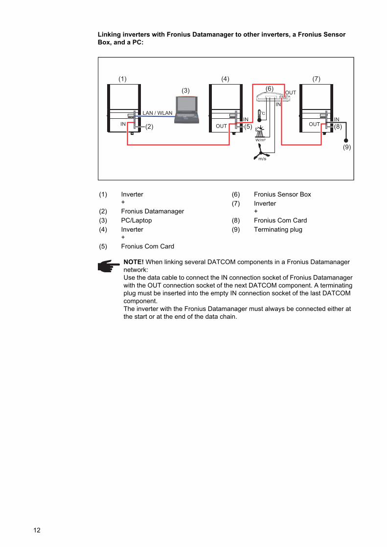
Linking inverters with Fronius Datamanager to other inverters, a Fronius Sensor Box, and a PC:
(1) Inverter+
(2) Fronius Datamanager
(3) PC/Laptop
(4) Inverter+
(5) Fronius Com Card
(6) Fronius Sensor Box
(7) Inverter+
(8) Fronius Com Card
(9) Terminating plug
NOTE! When linking several DATCOM components in a Fronius Datamanager network:Use the data cable to connect the IN connection socket of Fronius Datamanager with the OUT connection socket of the next DATCOM component. A terminating plug must be inserted into the empty IN connection socket of the last DATCOM component.The inverter with the Fronius Datamanager must always be connected either at the start or at the end of the data chain.
IN
IN
INOUT
OUT
OUTIN
(1)(6)
(4) (7)
(2)
(3)
(5) (8)
LAN / WLAN
(9)
12
EN
-US
Calculating the data volume
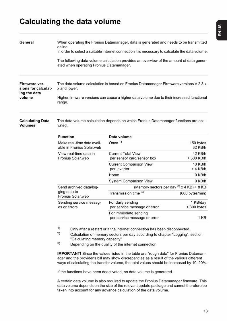
General When operating the Fronius Datamanager, data is generated and needs to be transmitted online.In order to select a suitable internet connection it is necessary to calculate the data volume.
The following data volume calculation provides an overview of the amount of data gener-ated when operating Fronius Datamanager.
Firmware ver-sions for calculat-ing the data volume
The data volume calculation is based on Fronius Datamanager Firmware versions V 2.3.x-x and lower.
Higher firmware versions can cause a higher data volume due to their increased functional range.
Calculating Data Volumes
The data volume calculation depends on which Fronius Datamanager functions are acti-vated.
1) Only after a restart or if the internet connection has been disconnected2) Calculation of memory sectors per day according to chapter "Logging", section
"Calculating memory capacity"3) Depending on the quality of the internet connection
IMPORTANT! Since the values listed in the table are "rough data" for Fronius Dataman-ager and the provider's bill may show discrepancies as a result of the various different ways of calculating the transfer volume, the total values should be increased by 10–20%.
If the functions have been deactivated, no data volume is generated.
A certain data volume is also required to update the Fronius Datamanager firmware. This data volume depends on the size of the relevant update package and cannot therefore be taken into account for any advance calculation of the data volume.
Function Data volume
Make real-time data avail-able in Fronius Solar.web
Once 1) 150 bytes32 KB/h
View real-time data in Fronius Solar.web
Current Total View per sensor card/sensor box
42 KB/h + 300 KB/h
Current Comparison View per inverter
13 KB/h + 4 KB/h
Home 0 KB/h
System Comparison View 0 KB/h
Send archived data/log-ging data to Fronius Solar.web
(Memory sectors per day 2) x 4 KB) + 8 KB
Transmission time 3) (600 bytes/min)
Sending service messag-es or errors
For daily sending per service message or error
1 KB/day+ 300 bytes
For immediate sending per service message or error 1 KB
13

IMPORTANT! Fronius recommends a flat rate in order to avoid unforeseeable data vol-umes.
Calculation exam-ples
Example 1 - Home System
1 inverter;No Fronius Sensor Card/Box;Fronius Datamanager has a 24-hour internet connection;
+ 0.15 KB
+ 32 KB/h x 24 h = 768 KB
Archived data is sent to Fronius So-lar.web;30 minutes transfer time;inverters operate 14 h/day;15 minutes storage interval;(This results in 1 memory sector per day in accordance with the section "Calculating memory capacity")
+ 0.6 KB/min x 30 min = 18 KB
+ (1 memory sector/day x 4 KB) + 8 KB = 12KB
Real-time data is viewed over a 15-minute period every day
+ 42 KB/h x 0.25 h = 10.5 KB
1 service message sent each day to con-firm average error rate
+ 1 service message x 1 KB = 1 KB
Subtotal without safety 0.15 KB768.00 KB18.00 KB12.00 KB10.50 KB
1.00 KB
809.65 KB
A 10% safety factor is added to the calcu-lation
809.65 KB + 10%
Final result 890.615 KB/day
14

EN
-US
Example 2 - Large System100 inverters;10 sensor cards/sensor boxes;Fronius Datamanager has a 24-hour internet connection;
+ 0.15 KB
+ 32 KB/h x 24 h = 768 KB
Archived data is sent to Fronius So-lar.web;120 minutes transfer time;inverters operate 14 h/day;5 minutes storage interval;(This results in 173 memory sectors per day in accordance with the section "Calcu-lating memory capacity")
+ 0.6 KB/min x 120 min = 72 KB
+ (173 memory sectors/day x 4 KB)+ 8 KB
= 700 KB
The current Total View and the current Comparison View are viewed over a two-hour period every day
+ 42 KB/h x 2 h+ 300 KB/h x 10 x 2 h
+ (13 KB/h + 100 x 4 KB/h) x 2 h= 6910 KB
50 service messages sent each day to confirm average error rate
+ 50 service messages x 1 KB = 50 KB
Subtotal without safety 0.15 KB768.00 KB72.00 KB
700.00 KB6910.00 KB
50.00 KB
8,500.15 KB
A 10% safety factor is added to the calcu-lation
8,500.15 KB + 10%
Final result 9,350.165 KB/day(approx. 9.35 MB/day)
15

General information for the network administrator
Requirements
If Fronius Datamanager is being integrated into an existing network, the Fronius Dataman-ager address must be adapted to the network.
Example: Network address range = 192.168.1.x, subnet mask = 255.255.255.0
- An IP address between 192.168.1.1 and 192.168.1.254 must be assigned to Fronius Datamanager.
- The IP address selected may not be already assigned in the network.- The subnet mask must correspond to the existing network (e.g. 255.255.255.0).
If Fronius Datamanager will be sending service messages and/or data to Fronius So-lar.web, then a gateway address and a DNS server address must also be entered. Fronius Datamanager uses the gateway address to access the Internet. The IP address of the DSL router can be used as a gateway address, for example.
IMPORTANT!- Fronius Datamanager may not have the same IP address as the PC/laptop!- Fronius Datamanager cannot connect to the Internet spontaneously. A router must be
used for a DSL connection to the Internet.
If you are using the WLAN network connection, the Fronius Datamanager must be equipped with a WLAN function and a WLAN antenna suitable for the inverter.
General firewall settings
The firewall must be configured as follows in order to use the different Fronius Dataman-ager functions:
Service messages are sent via Fronius Solar.web.
Sending service messages via a DSL Internet con-nection
Normally, no additional router configuration is required for a regular DSL Internet connec-tion for accessing 'Fronius Solar.web' and/or sending service messages, because connec-tions from the LAN to the Internet are open.
NOTE! Configuring a network for Fronius Datamanager requires knowledge of network technology.
49049/UDP output
15015/TCPinput
80/TCPinput
Sending service messages x - -
Connecting to datalogger via ‘Fro-nius Solar.web’
x - -
Connecting to datalogger via ‘Fro-nius Solar.access’
- x x
Access to the Fronius Dataman-ager web interface
- - x
16

EN
-US
Using Fronius So-lar.web and send-ing service messages
However, an internet connection is required to use Fronius Solar.web and send service messages.
Fronius Datamanager cannot connect to the Internet spontaneously. A router must be used for a DSL connection to the Internet.
17
Controls, connections and indicators
Safety
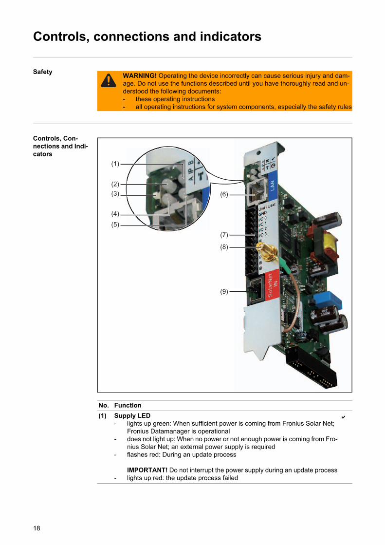
Controls, Con-nections and Indi-cators
WARNING! Operating the device incorrectly can cause serious injury and dam-age. Do not use the functions described until you have thoroughly read and un-derstood the following documents:- these operating instructions- all operating instructions for system components, especially the safety rules
No. Function
(1) Supply LED- lights up green: When sufficient power is coming from Fronius Solar Net;
Fronius Datamanager is operational- does not light up: When no power or not enough power is coming from Fro-
nius Solar Net; an external power supply is required- flashes red: During an update process
IMPORTANT! Do not interrupt the power supply during an update process- lights up red: the update process failed
(1)
(2)(3)
(4)
(5)
(6)
(7)
(8)
(9)
18
EN
-US
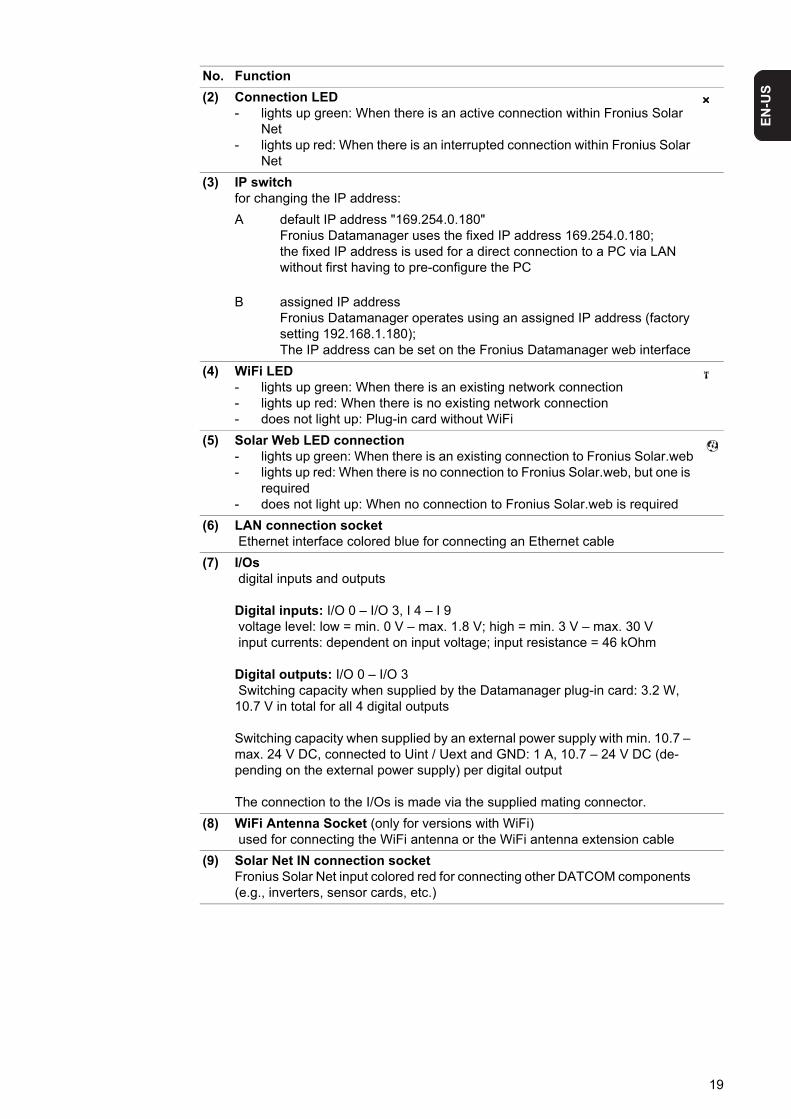
(2) Connection LED- lights up green: When there is an active connection within Fronius Solar
Net- lights up red: When there is an interrupted connection within Fronius Solar
Net
(3) IP switchfor changing the IP address:
A default IP address "169.254.0.180" Fronius Datamanager uses the fixed IP address 169.254.0.180;the fixed IP address is used for a direct connection to a PC via LAN without first having to pre-configure the PC
B assigned IP addressFronius Datamanager operates using an assigned IP address (factory setting 192.168.1.180); The IP address can be set on the Fronius Datamanager web interface
(4) WiFi LED- lights up green: When there is an existing network connection- lights up red: When there is no existing network connection- does not light up: Plug-in card without WiFi
(5) Solar Web LED connection- lights up green: When there is an existing connection to Fronius Solar.web- lights up red: When there is no connection to Fronius Solar.web, but one is
required- does not light up: When no connection to Fronius Solar.web is required
(6) LAN connection socket Ethernet interface colored blue for connecting an Ethernet cable
(7) I/Os digital inputs and outputs
Digital inputs: I/O 0 – I/O 3, I 4 – I 9 voltage level: low = min. 0 V – max. 1.8 V; high = min. 3 V – max. 30 V input currents: dependent on input voltage; input resistance = 46 kOhm
Digital outputs: I/O 0 – I/O 3 Switching capacity when supplied by the Datamanager plug-in card: 3.2 W, 10.7 V in total for all 4 digital outputs
Switching capacity when supplied by an external power supply with min. 10.7 – max. 24 V DC, connected to Uint / Uext and GND: 1 A, 10.7 – 24 V DC (de-pending on the external power supply) per digital output
The connection to the I/Os is made via the supplied mating connector.
(8) WiFi Antenna Socket (only for versions with WiFi) used for connecting the WiFi antenna or the WiFi antenna extension cable
(9) Solar Net IN connection socketFronius Solar Net input colored red for connecting other DATCOM components (e.g., inverters, sensor cards, etc.)
No. Function
19
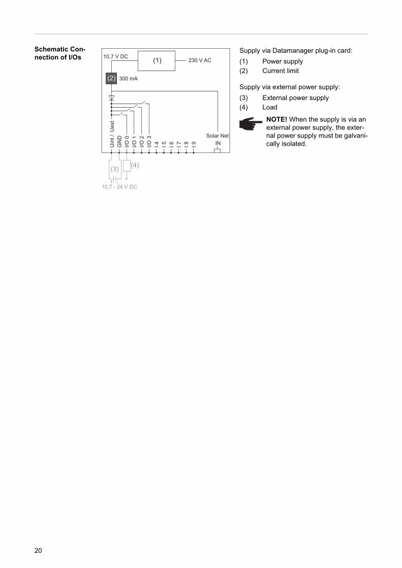
Schematic Con-nection of I/Os
Supply via Datamanager plug-in card:
(1) Power supply
(2) Current limit
Supply via external power supply:
(3) External power supply
(4) LoadU
int /
Uex
tG
ND
I/O 0
I/O 1
I/O 2
I/O 3
I 4 I 5 I 6 I 7 I 8 I 9
(1)
(4)
Solar Net IN
230 V AC10,7 V DC
(2) 300 mA
+ -10,7 - 24 V DC
(3)
NOTE! When the supply is via an external power supply, the exter-nal power supply must be galvani-cally isolated.
20
EN
-US
Cabling
Fronius Solar Net clients
Inverters with Fronius Datamanager or Fronius Com Card, DATCOM components with ex-ternal housing or other DATCOM components will hereinafter be referred to as Fronius So-lar Net.
Fronius Solar Net Client Cabling
The data connection for the Fronius Solar Net client is a 1:1 connection using 8-pin data cables and RJ-45 plugs.The overall line length in a Fronius Solar Net ring must not exceed 1000 m.
Requirements for the Solar Net Data Cables
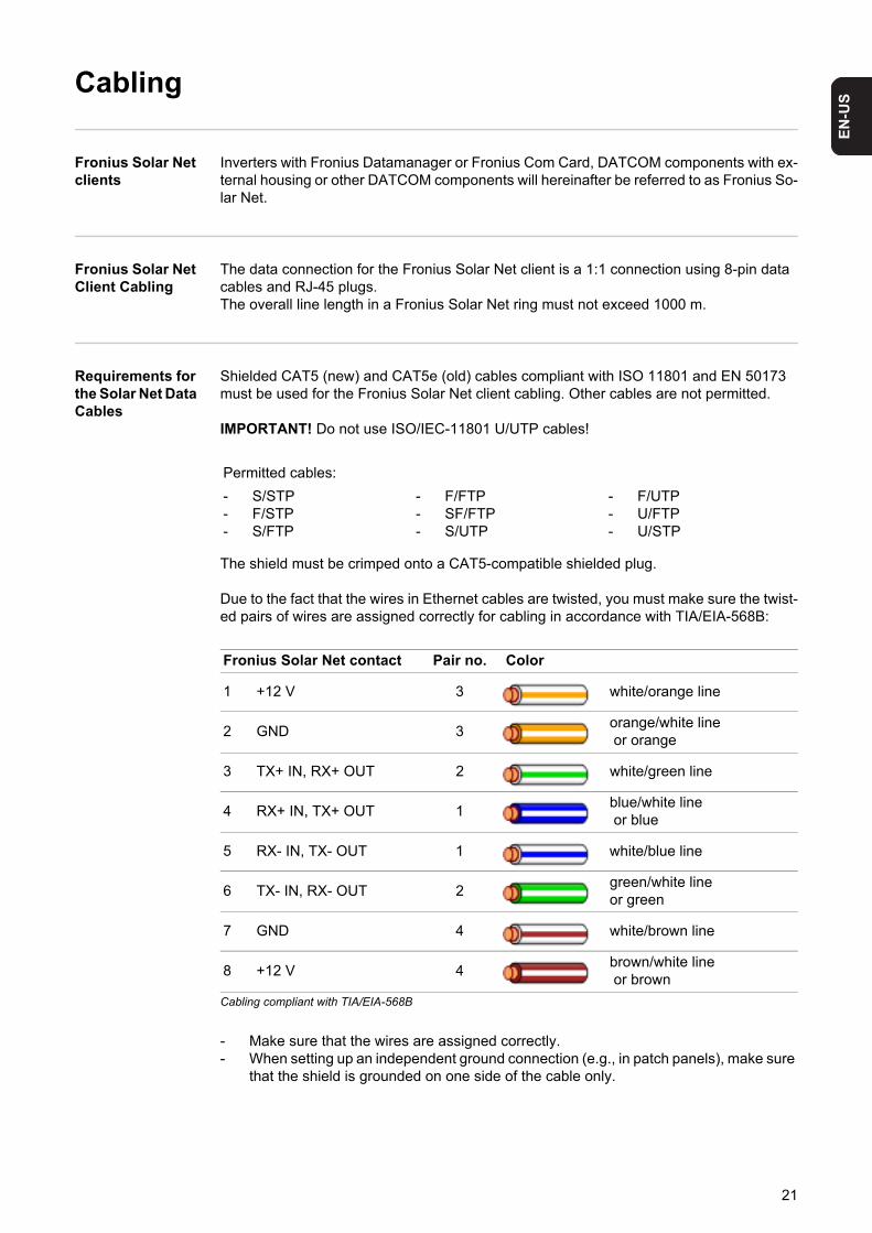
Shielded CAT5 (new) and CAT5e (old) cables compliant with ISO 11801 and EN 50173 must be used for the Fronius Solar Net client cabling. Other cables are not permitted.
IMPORTANT! Do not use ISO/IEC-11801 U/UTP cables!
The shield must be crimped onto a CAT5-compatible shielded plug.
Due to the fact that the wires in Ethernet cables are twisted, you must make sure the twist-ed pairs of wires are assigned correctly for cabling in accordance with TIA/EIA-568B:
Cabling compliant with TIA/EIA-568B
- Make sure that the wires are assigned correctly.- When setting up an independent ground connection (e.g., in patch panels), make sure
that the shield is grounded on one side of the cable only.
Permitted cables:
- S/STP- F/STP- S/FTP
- F/FTP- SF/FTP- S/UTP
- F/UTP- U/FTP- U/STP
Fronius Solar Net contact Pair no. Color
1 +12 V 3 white/orange line
2 GND 3orange/white line or orange
3 TX+ IN, RX+ OUT 2 white/green line
4 RX+ IN, TX+ OUT 1blue/white line or blue
5 RX- IN, TX- OUT 1 white/blue line
6 TX- IN, RX- OUT 2green/white line or green
7 GND 4 white/brown line
8 +12 V 4brown/white line or brown
21

The following structured cabling standards must generally be observed:- EN 50173-1 for Europe- ISO/IEC 11801:2002 internationally- TIA/EIA 568 for North America
Rules for use of copper cables apply.
Preassembled data cables
The following preassembled data cables are available from Fronius:- CAT5 cable 1 m ... 43,0004,2435- CAT5 cable 20 m ... 43,0004,2434- CAT5 cable 60 m ... 43,0004,2436
The cables listed above are 8-pin, 1:1 LAN network cables, shielded and twisted, including RJ 45 plugs.
IMPORTANT! Data cables are not UV resistant. They should be protected from sunlight when laid outdoors.
22

Installing Fronius Datamanager


EN
-US
Installing Fronius Datamanager – LAN overview
Safety
Installing Fronius Datamanager – LAN Overview
Adjust the network settings for the Fronius Datamanager on the PC/laptop
Insert Fronius Datamanager into the inverter
Insert blue Ethernet cable into Fronius Datamanager (LAN connection socket)
Insert terminating plug into Fronius Datamanager (Solar Net IN connection socket)
Insert blue Ethernet cable into the PC/laptop
Switch IP switch on Fronius Datamanager to position - A -
Close the inverter and switch it on
After approx. 1 minute, open the browser on the PC/laptop and enter the following ad-dress:http://169.254.0.180
The Fronius Datamanager web interface appears.
Upon initial installation of Fronius Datamanager a message indicating the time and date is displayed.
Click on the message and set the time and date
If the message does not appear:Settings / TIME/DATE / Set Time and Date
WARNING! Operating the device incorrectly can cause serious injury and dam-age. Do not use the functions described until you have thoroughly read and un-derstood the following documents:- these operating instructions- all operating instructions for system components, especially the safety rules
NOTE! Installing Fronius Datamanager requires knowledge of network technolo-gy.
See section "Adjusting network settings for PC/laptop"
See section "Inserting Fronius Datamanager into an inverter"
See section "Installing Fronius Datamanager in Fronius Solar Net"
NOTE! If a connection to Fronius Datamanager is not established, check the net-work settings:- System Controls / Network and Sharing Center / LAN Connection / Proper-
ties (General) / Internet Protocol (TCP/IP) / Properties / Activate "Obtain IP Address Automatically" + "Obtain DNS Server Address Automatically"
- Internet Browser / Extras / Internet Options / Connections / LAN Settings / Deactivate "Use Proxy Server for LAN"
See section "Starting for the First Time – Opening the Fronius Dataman-ager Web Interface"
1
2
345
678
9
25

Settings / Internet Connection / LAN – save
Settings / LAN / select: "dynamic"(assign host name) or "static" (enter data)
Settings / SOLAR.WEB / Enter Data, save
System Information / Note Datalogger ID (required for registration in Solar.web)
Turn off and open inverters
Switch IP switch on Fronius Datamanager back to position - B -
Close the inverter and switch it on
Disconnect the blue Ethernet cable from PC/laptop
Insert the blue Ethernet cable into the router
See section "Settings – Time/Date"
See section "Settings – Internet Connections"
See section "Settings – LAN"
See section "Settings – Solar.web"
See section "Services – System Information"
See section "Starting up Fronius Datamanager – LAN"
10
1111
12
13
1415161718
26
EN
-US
Installing Fronius Datamanager – WiFi overview
Safety
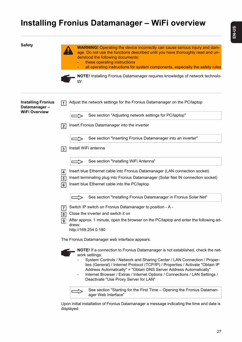
Installing Fronius Datamanager – WiFi Overview
Adjust the network settings for the Fronius Datamanager on the PC/laptop
Insert Fronius Datamanager into the inverter
Install WiFi antenna
Insert blue Ethernet cable into Fronius Datamanager (LAN connection socket)
Insert terminating plug into Fronius Datamanager (Solar Net IN connection socket)
Insert blue Ethernet cable into the PC/laptop
Switch IP switch on Fronius Datamanager to position - A -
Close the inverter and switch it on
After approx. 1 minute, open the browser on the PC/laptop and enter the following ad-dress:http://169.254.0.180
The Fronius Datamanager web interface appears.
Upon initial installation of Fronius Datamanager a message indicating the time and date is displayed.
WARNING! Operating the device incorrectly can cause serious injury and dam-age. Do not use the functions described until you have thoroughly read and un-derstood the following documents:- these operating instructions- all operating instructions for system components, especially the safety rules
NOTE! Installing Fronius Datamanager requires knowledge of network technolo-gy.
See section "Adjusting network settings for PC/laptop"
See section "Inserting Fronius Datamanager into an inverter"
See section "Installing WiFi Antenna"
See section "Installing Fronius Datamanager in Fronius Solar Net"
NOTE! If a connection to Fronius Datamanager is not established, check the net-work settings:- System Controls / Network and Sharing Center / LAN Connection / Proper-
ties (General) / Internet Protocol (TCP/IP) / Properties / Activate "Obtain IP Address Automatically" + "Obtain DNS Server Address Automatically"
- Internet Browser / Extras / Internet Options / Connections / LAN Settings / Deactivate "Use Proxy Server for LAN"
See section "Starting for the First Time – Opening the Fronius Dataman-ager Web Interface"
1
2
3
456
789
27

Click on the message and set the time and date
If the message does not appear:Settings / TIME/DATE / Set Time and Date
Settings / Internet Connection / WiFi – save
Settings / WiFi / select: "dynamic" (assign host name) or "static" (enter data)
Settings / WiFi MANAGEMENT / Update Networks
Settings / SOLAR.WEB / Enter Data, save
System Information / Note Datalogger ID (required for registration in Solar.web)
Turn off and open inverters
Switch IP switch on Fronius Datamanager back to position - B -
Disconnect the blue Ethernet cable from Fronius Datamanager
Close the inverter and switch it on
Disconnect the blue Ethernet cable from PC/laptop
See section "Settings – Time/Date"
See section "Settings – Internet Connections"
See section "Settings – WiFi"
See section "Settings – WiFi Management"
See section "Settings – Solar.web"
See section "Services – System Information"
See section "Starting up Fronius Datamanager – WiFi"
10
1111
12
13
14
15
1617181920
28
EN
-US
Network settings for PC/laptop
General The PC/laptop is also a member of the network and must also be assigned a unique net-work address like Fronius Datamanager.
If the PC is already integrated in the network, no further settings are required.
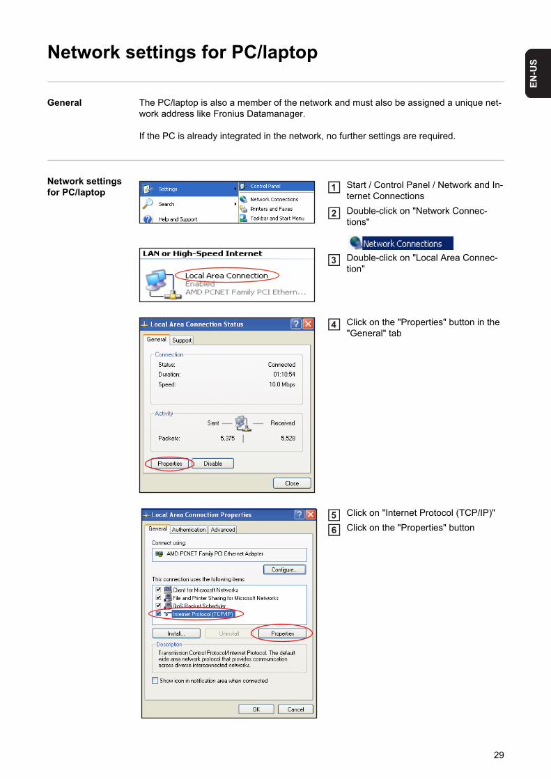
Network settings for PC/laptop
Start / Control Panel / Network and In-ternet Connections
Double-click on "Network Connec-tions"
Double-click on "Local Area Connec-tion"
Click on the "Properties" button in the "General" tab
Click on "Internet Protocol (TCP/IP)"
Click on the "Properties" button
1
2
3
4
56
29

The "Internet Protocol (TCP/IP) Properties" window will appear.
If a DHCP server is available in the network:
Select "Obtain an IP address automatically"7
30

EN
-US
If a DHCP server is not available in the network:
Activate "Obtain DNS server address automatically"
Internet options for PC/laptop
Open the internet browser (e.g. Micro-soft Internet Explorer)
Click on "Tools"
Click on "Internet Options"
Click on the "Connections" tab
7a Select "Use the following IP address"
7b Assign a unique IP address to the PC/laptop
Example: Network address range = 192.168.1.x, subnet mask = 255.255.255.0
- An IP address between 192.168.1.1 and 192.168.1.254 must be assigned to the PC/laptop.
- The IP address selected may not be already assigned in the network.- The subnet mask must correspond to the existing network (e.g. 255.255.255.0).- The "Default gateway" setting is not relevant for the Fronius Datamanager con-
nection.
IMPORTANT! The PC/laptop must not have the same IP address as Fronius Data-manager!
8
1
23
4
31
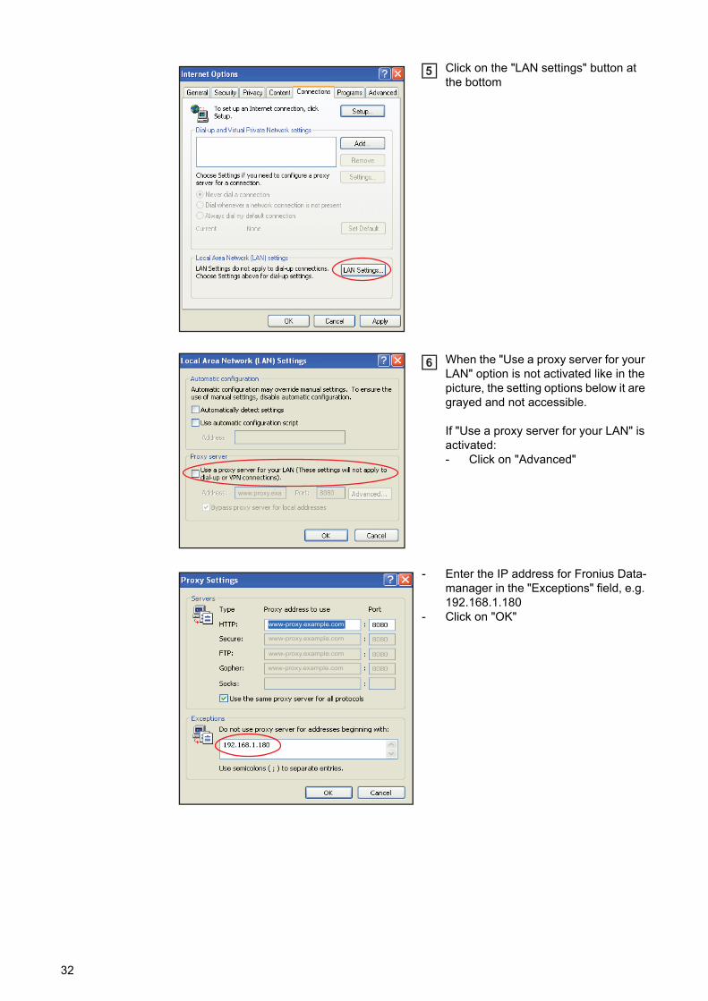
Click on the "LAN settings" button at the bottom
When the "Use a proxy server for your LAN" option is not activated like in the picture, the setting options below it are grayed and not accessible.
If "Use a proxy server for your LAN" is activated:- Click on "Advanced"
- Enter the IP address for Fronius Data-manager in the "Exceptions" field, e.g. 192.168.1.180
- Click on "OK"
5
www.proxy.exa
6
www-proxy.example.com
www-proxy.example.com
www-proxy.example.com
www-proxy.example.com
32

EN
-US
Inserting Fronius Datamanager into an inverter
General Please see the operating instructions for the respective inverter for information regarding plug-in card installation. Please note the safety and warning information in your inverter's operating instructions.
IMPORTANT! Before inserting the Fronius Datamanager plug-in card, remove any exist-ing Fronius Com Card, Fronius Power Control Card, or Fronius Modbus Card!
SafetyWARNING! An electric shock can be fatal. Danger from grid voltage and DC volt-age from solar modules.- The connection area should only be opened by a licensed electrician.- The separate power stage set area should only be disconnected from the
connection area after first being disconnected from the grid power.- The separate power stage set area should only be opened by Fronius-trained
service personnel.
Before making any connections, make sure that the AC and DC sides are discon-nected from the inverter, e.g.:- Switch off the AC automatic circuit breaker for the inverter- Cover solar modules
Please observe the 5 safety rules.
WARNING! An electric shock can be fatal. Danger from residual voltage from ca-pacitors. You must wait until the capacitors have discharged.
NOTE! Follow general ESD precautions when handling plug-in cards.
33

Fronius Dataman-ager plug-in posi-tions
The Fronius Datamanager plug-in position is specified for each inverter type:
*) If an ENS plug-in card has been inserted into an ENS slot:Insert Fronius Datamanager in the next slot to the right of the ENS slot.
IMPORTANT!The next slot must remain empty!Do not remove an inserted ENS plug-in card under any circumstances!
Inverter Plug-in position
Fronius IG 15 - 60 ENS plug *)
Fronius IG 300 - 500 ENS plug *)
Fronius IG Plus, Fronius IG Plus V
on the far right, unless a ML-MON plug-in card is present
Fronius CL on the far right, unless a ML-MON plug-in card is present
EN
S
Dat
aman
ager
34

EN
-US
Installing and connecting WLAN antennas
General If the Fronius Datamanager is equipped with WLAN, the WLAN antenna must be installed either inside or outside the inverter, depending on which inverter is being used.
IMPORTANT! Always follow the relevant operating instructions when opening an inverter.Observe the safety guidelines.
Fronius IG, Fro-nius IG Plus, Fro-nius IG Plus V, Fronius CL: In-stalling and con-necting antennas
Use the double-sided adhesive tape to fasten the mounting bracket to the out-side of the inverter housing or, if sui-table for the antenna cable, secure it in a position near the inverter
IMPORTANT! The double-sided adhe-sive tape only reaches its maximum bond strength after 24 hours.
IMPORTANT! The mounting bracket may not be screwed to the inverter housing.It may however be fitted in a nearby po-sition. The relevant screws are not in-cluded in the scope of delivery and must be selected by the installer.
Connect the antenna cable to Fronius Datamanager
Run the antenna cable out through the "DATCOM Opening" on the inverter
If possible, secure the cable with a strain relief device
Close or seal the "DATCOM Opening" in accordance with the inverter opera-ting instructions
2
1
1
1
20,8 - 1,1 Nm
2
3
4
5
35

Remove the hex nut and washer from the outside thread of the antenna cable
Run the antenna cable through the drill hole on the mounting bracket
Attach the lock washer and screw on the hex nut
Screw on the antenna
1
2
6
NOTE! To avoid damaging the antenna, only use the hexagonal head to fasten the antenna.
6
1
5
0,8 - 1,1 Nm
2
34
7
8
9
36

EN
-US
Fronius IG USA, Fronius IG Plus USA, Fronius IG Plus V USA: In-stalling and Con-necting Antennas
1
2
11
2
CAUTION! Danger of short circuit caused by loose metal parts from knockouts. Loose metal parts in the inverter may cause short circuits when the inverter is powered up. When removing knockouts, make sure that - no loose metal parts fall into the inverter- any metal pieces that do fall into the inverter are removed immediately.
1
2
3
119 mm3/4 in.
4
NOTE! In order to ensure leak-tightness, the sealing ring must be fitted to the an-tenna screw joint before inserting the antenna screw joint into the inverter hous-ing.
! !
1
2
5
1
6
37

* Bending radius of the antenna cable: at least 25.4 mm/1 in.
8 Nm5.90 ft. lb.
7
33
1
2
*
8
NOTE! To avoid damaging the antenna, only use the hexagonal head to fasten the antenna.
1
0.8 - 1.1 Nm0.59-0.81 ft. lb.
9
10.8 - 1.1 Nm0.59-0.81 ft. lb.
10
38
EN
-US
Installing Fronius Datamanager in Fronius Solar Net
Installing Invert-ers with Fronius Datamanager in Fronius Solar Net
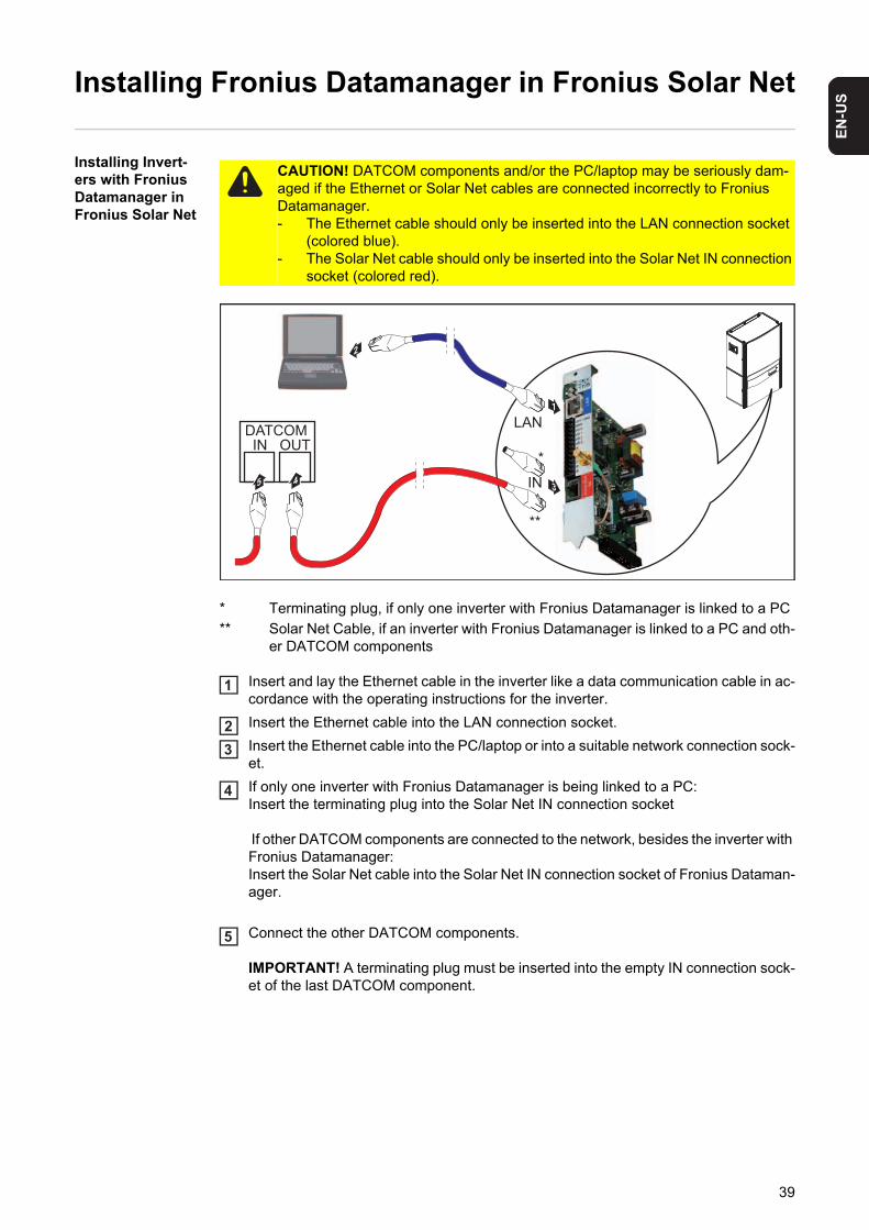
* Terminating plug, if only one inverter with Fronius Datamanager is linked to a PC
** Solar Net Cable, if an inverter with Fronius Datamanager is linked to a PC and oth-er DATCOM components
Insert and lay the Ethernet cable in the inverter like a data communication cable in ac-cordance with the operating instructions for the inverter.
Insert the Ethernet cable into the LAN connection socket.
Insert the Ethernet cable into the PC/laptop or into a suitable network connection sock-et.
If only one inverter with Fronius Datamanager is being linked to a PC:Insert the terminating plug into the Solar Net IN connection socket
If other DATCOM components are connected to the network, besides the inverter with Fronius Datamanager:Insert the Solar Net cable into the Solar Net IN connection socket of Fronius Dataman-ager.
Connect the other DATCOM components.
IMPORTANT! A terminating plug must be inserted into the empty IN connection sock-et of the last DATCOM component.
CAUTION! DATCOM components and/or the PC/laptop may be seriously dam-aged if the Ethernet or Solar Net cables are connected incorrectly to Fronius Datamanager.- The Ethernet cable should only be inserted into the LAN connection socket
(colored blue).- The Solar Net cable should only be inserted into the Solar Net IN connection
socket (colored red).
DATCOMIN OUT
2
45 IN
LAN
3
1
**
*
1
23
4
5
39

Starting for the First Time – Opening the Fronius Datamanager Web Interface
Starting for the First Time – Opening the Fro-nius Dataman-ager Web Interface
To start up Fronius Datamanager, the plug-in card must be installed in the inverter and in the Fronius Solar Net.
In the inverter on the Fronius Datamanager, switch the IP switch to position - A - as per the figure:
Close and switch on the inverter in accordance with the operating instructions
Wait for approx. 1 minute until the connection to Fronius Datamanager is established. In the task bar of the PC/laptop, the "Connectivity" symbol can be displayed:
Open the PC's/laptop's internet browser (e.g., Microsoft Internet Explorer)
Enter the following address in the address field: http://169.254.0.180;
the Fronius Datamanager web interface will appear
WARNING! An electric shock can be fatal. Danger from grid voltage and DC volt-age from solar modules.Before opening the inverter:- You must wait until the capacitors have discharged.- Follow the operating instructions when opening the inverter.- Observe the safety rules and safety instructions contained in the inverter's
operating instructions.
1
Pos. A Pos. B
1
23
NOTE! If a connection to Fronius Datamanager is not established, check the net-work settings:- System Controls / Network and Sharing Center / LAN Connection / Proper-
ties (General) / Internet Protocol (TCP/IP) / Properties / Activate "Obtain IP Address Automatically" + "Obtain DNS Server Address Automatically"
- Internet Browser / Extras / Internet Options / Connections / LAN Settings / Deactivate "Use Proxy Server for LAN"
45
40

EN
-US
Fronius Dataman-ager Web Inter-face – Overview
The following data is displayed on the Fronius Datamanager web interface:
(1) Current comparison view of all inverters in the Fronius Solar Net ring
(2) System overview: Current / Day / Year / Total
(3) Inverters
(4) Sensors
(5) Services system information, network diagnostics, firmware update
(6) The Settings menu
(7) Other setting options
(1)
(7)(2)
(3)(4)
(5)
(6)
41
The Settings Menu
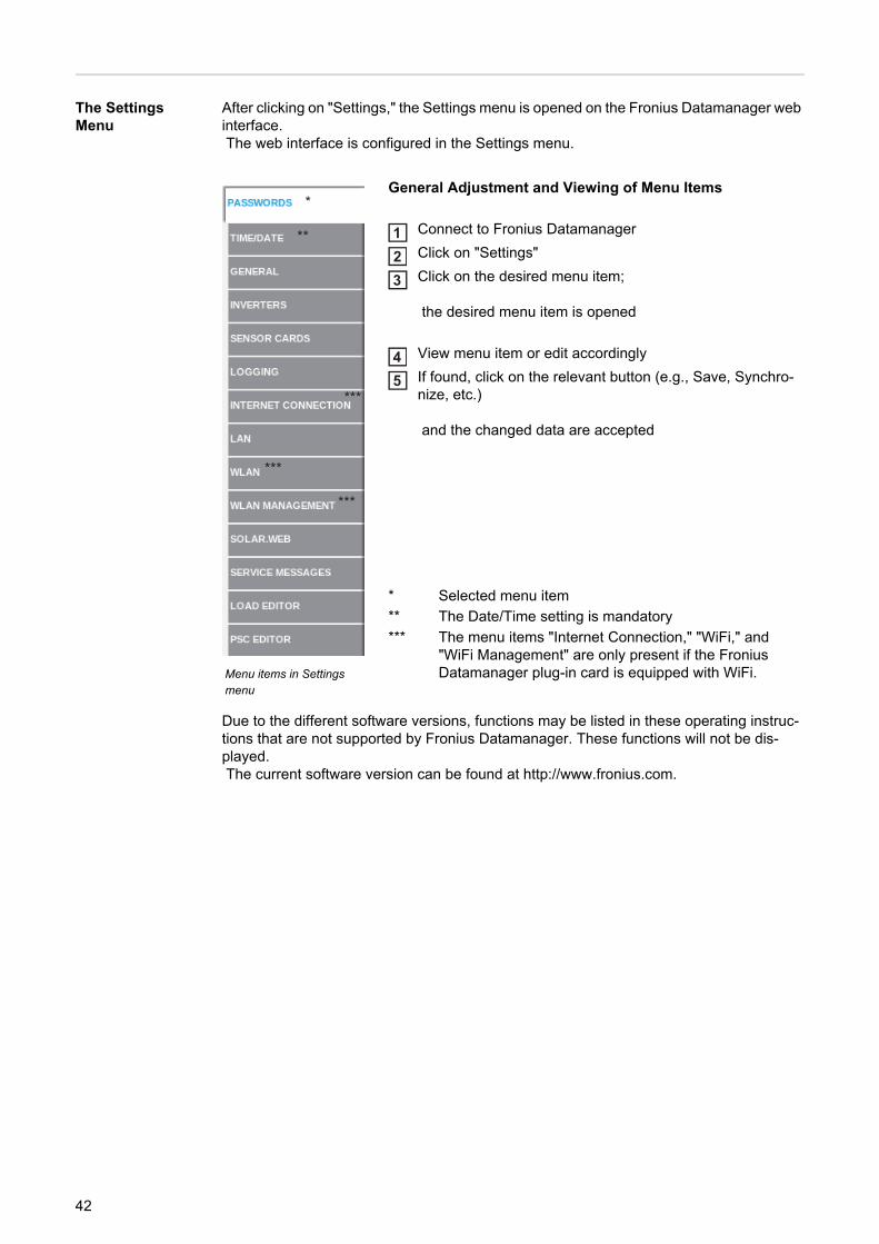
After clicking on "Settings," the Settings menu is opened on the Fronius Datamanager web interface. The web interface is configured in the Settings menu.
Due to the different software versions, functions may be listed in these operating instruc-tions that are not supported by Fronius Datamanager. These functions will not be dis-played. The current software version can be found at http://www.fronius.com.
Menu items in Settings menu
General Adjustment and Viewing of Menu Items
Connect to Fronius Datamanager
Click on "Settings"
Click on the desired menu item;
the desired menu item is opened
View menu item or edit accordingly
If found, click on the relevant button (e.g., Save, Synchro-nize, etc.)
and the changed data are accepted
* Selected menu item
** The Date/Time setting is mandatory
*** The menu items "Internet Connection," "WiFi," and "WiFi Management" are only present if the Fronius Datamanager plug-in card is equipped with WiFi.
*
***
**
***
***
123
45
42
EN
-US
Other settings op-tions
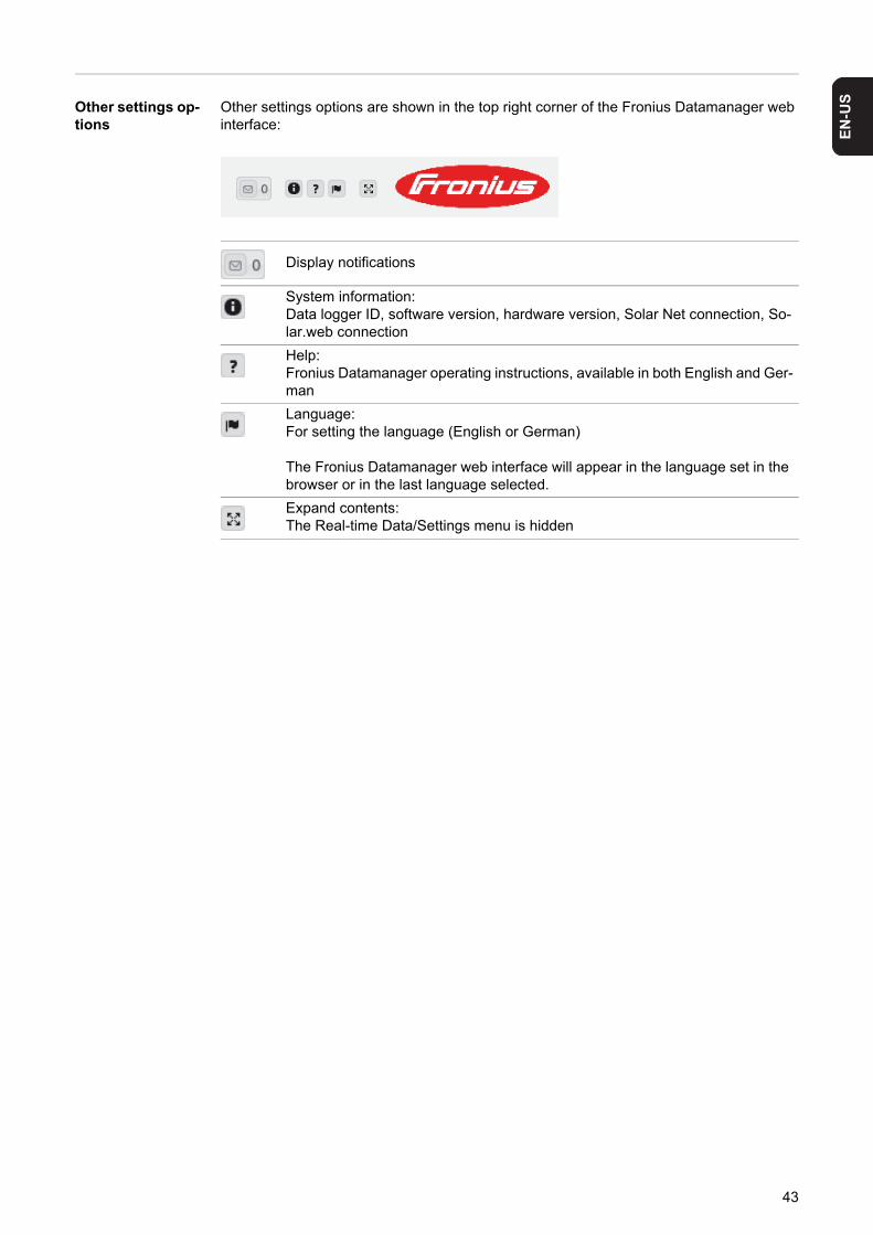
Other settings options are shown in the top right corner of the Fronius Datamanager web interface:
Display notifications
System information: Data logger ID, software version, hardware version, Solar Net connection, So-lar.web connection
Help:Fronius Datamanager operating instructions, available in both English and Ger-man
Language:For setting the language (English or German)
The Fronius Datamanager web interface will appear in the language set in the browser or in the last language selected.
Expand contents:The Real-time Data/Settings menu is hidden
43
Starting up Fronius Datamanager – LAN
Starting Up Fro-nius Dataman-ager – LAN
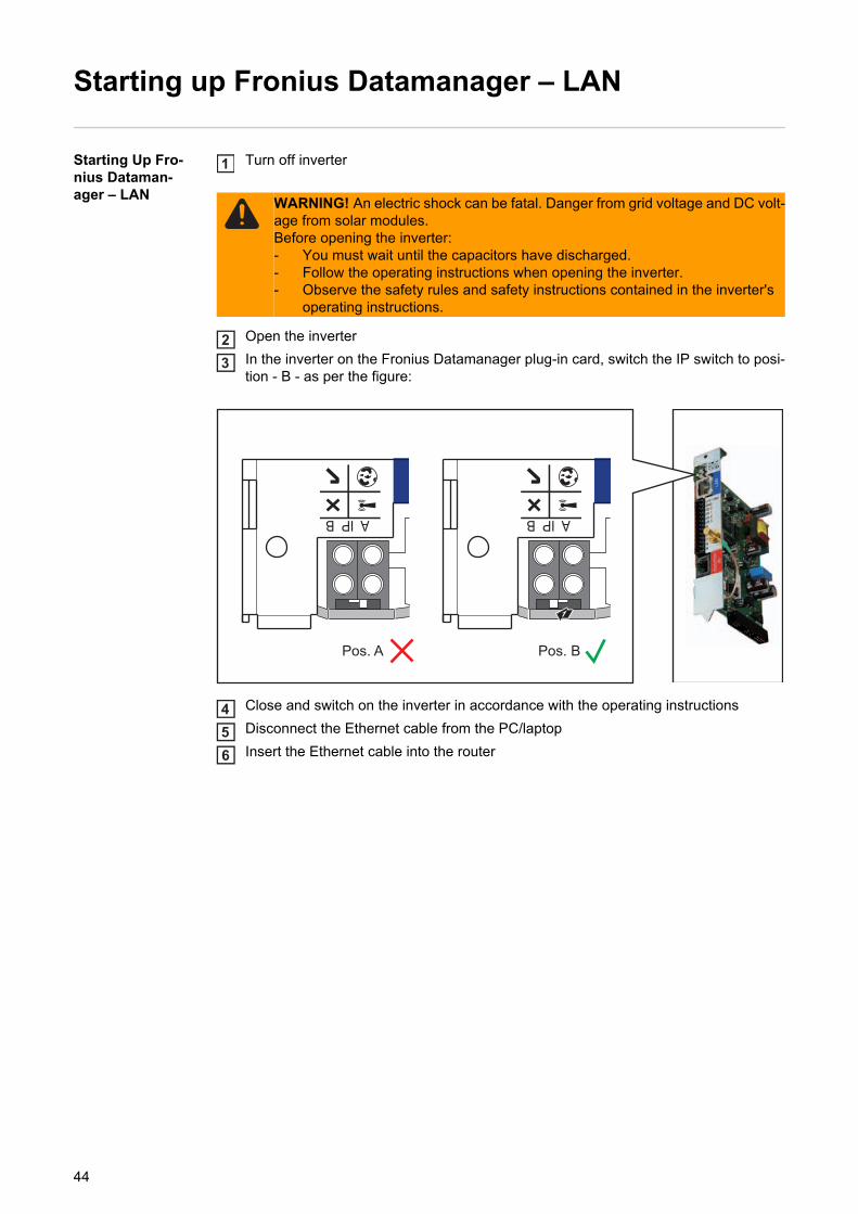
Turn off inverter
Open the inverter
In the inverter on the Fronius Datamanager plug-in card, switch the IP switch to posi-tion - B - as per the figure:
Close and switch on the inverter in accordance with the operating instructions
Disconnect the Ethernet cable from the PC/laptop
Insert the Ethernet cable into the router
WARNING! An electric shock can be fatal. Danger from grid voltage and DC volt-age from solar modules.Before opening the inverter:- You must wait until the capacitors have discharged.- Follow the operating instructions when opening the inverter.- Observe the safety rules and safety instructions contained in the inverter's
operating instructions.
1
23
Pos. A Pos. B
1
456
44

EN
-US
Starting up Fronius Datamanager – WiFi
Starting Up Fro-nius Dataman-ager – WiFi
Turn off inverter
Open the inverter
In the inverter on the Fronius Datamanager plug-in card, switch the IP switch to posi-tion - B - as per the figure:
Disconnect the Ethernet cable from the Fronius Datamanager plug-in card and re-move from the inverter
Close and switch on the inverter in accordance with the operating instructions
WARNING! An electric shock can be fatal. Danger from grid voltage and DC volt-age from solar modules.Before opening the inverter:- You must wait until the capacitors have discharged.- Follow the operating instructions when opening the inverter.- Observe the safety rules and safety instructions contained in the inverter's
operating instructions.
1
23
Pos. A Pos. B
1
4
5
45

46
Connect to Fronius Datamanager

EN
-US
Connecting to Fronius Datamanager via internet browser
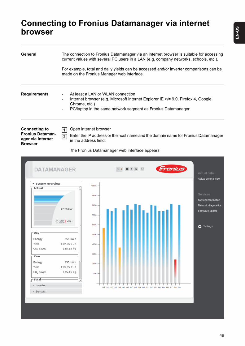
General The connection to Fronius Datamanager via an internet browser is suitable for accessing current values with several PC users in a LAN (e.g. company networks, schools, etc,).
For example, total and daily yields can be accessed and/or inverter comparisons can be made on the Fronius Manager web interface.
Requirements - At least a LAN or WLAN connection- Internet browser (e.g. Microsoft Internet Explorer IE >/= 9.0, Firefox 4, Google
Chrome, etc,)- PC/laptop in the same network segment as Fronius Datamanager
Connecting to Fronius Dataman-ager via Internet Browser
Open internet browser
Enter the IP address or the host name and the domain name for Fronius Datamanager in the address field;
the Fronius Datamanager web interface appears
12
49

For the network administrator
To access the Fronius Datamanager web interface outside of the LAN:- Configure the network router so that requests are forwarded to port 80/TCP on Fronius
Datamanager
50
EN
-US
Connecting to Fronius Datamanager via Fronius So-lar.access
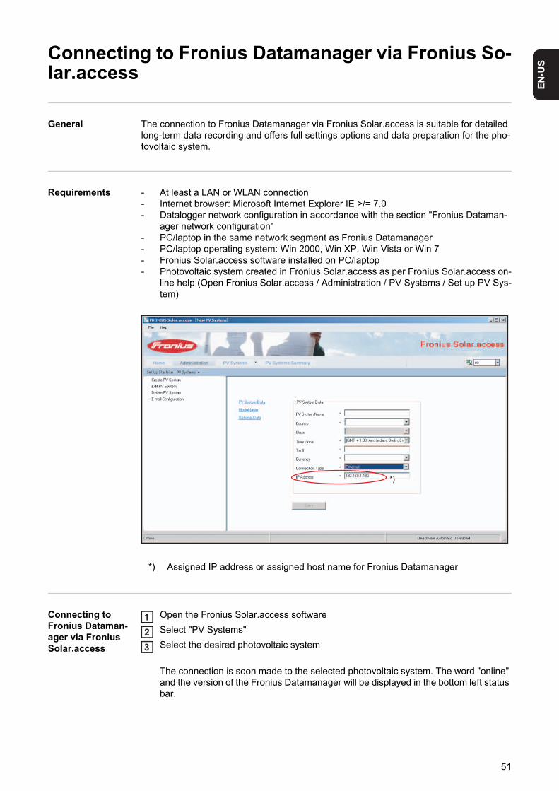
General The connection to Fronius Datamanager via Fronius Solar.access is suitable for detailed long-term data recording and offers full settings options and data preparation for the pho-tovoltaic system.
Requirements - At least a LAN or WLAN connection- Internet browser: Microsoft Internet Explorer IE >/= 7.0- Datalogger network configuration in accordance with the section "Fronius Dataman-
ager network configuration"- PC/laptop in the same network segment as Fronius Datamanager- PC/laptop operating system: Win 2000, Win XP, Win Vista or Win 7- Fronius Solar.access software installed on PC/laptop- Photovoltaic system created in Fronius Solar.access as per Fronius Solar.access on-
line help (Open Fronius Solar.access / Administration / PV Systems / Set up PV Sys-tem)
Connecting to Fronius Dataman-ager via Fronius Solar.access
Open the Fronius Solar.access software
Select "PV Systems"
Select the desired photovoltaic system
The connection is soon made to the selected photovoltaic system. The word "online" and the version of the Fronius Datamanager will be displayed in the bottom left status bar.
*) Assigned IP address or assigned host name for Fronius Datamanager
*)
123
51

For the network administrator
To access the Fronius Datamanager outside of the LAN:- Configure the network router so that requests are forwarded to port 80/TCP and port
15015/TCP on Fronius Datamanager
52

EN
-US
Connecting to Fronius Datamanager via the Internet and Fronius Solar.web
General By connecting to Fronius Datamanager via the Internet and Fronius Solar.web, you can ac-cess archived data and real-time photovoltaic system data online from anywhere in the world.You can also provide other users with guest access so that they can view your photovoltaic system, or you can make a comparison of several systems.
Function over-view
Fronius Datamanager is connected to the Internet (e.g. via a DSL router). Fronius Data-manager regularly logs on to Fronius Solar.web and sends its saved data every day. Fronius Solar.web can actively contact Fronius Datamanager, e.g. to display real-time da-ta.
Requirements - Internet access- Internet browser
IMPORTANT! Fronius Datamanager cannot connect itself to the Internet. A router must be used for a DSL connection to the Internet.
- Registration of photovoltaic system with Fronius Solar.web (1). The Fronius Datamanager ID is required for the registration. The ID is available in Set-tings/System Information.
- In order to access real-time data in Fronius Solar.web, the "Yes" selection option must be activated under "Send real-time data to Solar.web" in Fronius Datamanager (2).
- In order to access archived data in Fronius Solar.web, the "Daily at" or "Hourly" selec-tion option must be activated under "Send archived data to Solar.web" in Fronius Datamanager (3).
(1)
(2)
(3)
(3)
53

Accessing data from Fronius Datamanager via the Internet and Fronius So-lar.web
To access real-time and archived data from Fronius Datamanager using Fronius So-lar.web:
Open the "Solar Electronics" tab on the Fronius homepage (www.fronius.com)
Start Fronius Solar.web
For more information about Fronius Solar.web, see the online help.
For the network administrator
Configure the firewall so that the IP address of Fronius Datamanager can send data to port 49049/UDP of solarweb.fronius.com.
DSL routers usually enable you to send data to the Internet and therefore do not normally have to be configured.
12
54

Current Data in Fronius Datamanager

EN
-US
Current Data in Fronius Datamanager
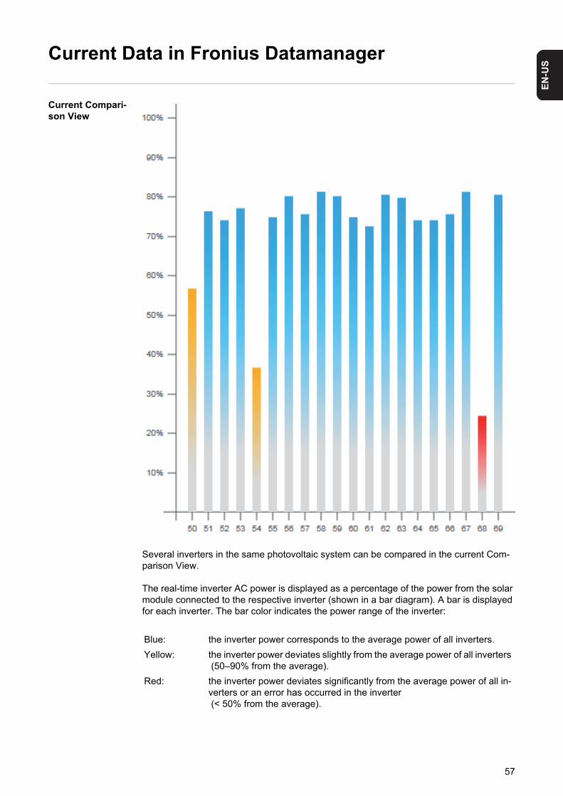
Current Compari-son View
Several inverters in the same photovoltaic system can be compared in the current Com-parison View.
The real-time inverter AC power is displayed as a percentage of the power from the solar module connected to the respective inverter (shown in a bar diagram). A bar is displayed for each inverter. The bar color indicates the power range of the inverter:
Blue: the inverter power corresponds to the average power of all inverters.
Yellow: the inverter power deviates slightly from the average power of all inverters (50–90% from the average).
Red: the inverter power deviates significantly from the average power of all in-verters or an error has occurred in the inverter (< 50% from the average).
57

System Overview The system overview contains:- the real-time power data of a photovol-
taic system- the active devices- the energy generated per day, per
year, and in total- the yield per day, per year, and in total- CO2 savings per day, per year, and in
total.
58

EN
-US
Inverter/Sensor View
Inverter View
The Inverter View displays all the inverters present in the system.
*) Clicking on an inverter or the cor-responding bar in the Comparison View displays the inverter's real-time data:
Sensor View
The Sensor View displays all the sensor cards/boxes present in the system.
*)
59

60
Fronius Datamanager Services


EN
-US
Services – System Information
System Informa-tion
(1) "Data logger Restart" button used to restart Fronius Datamanager
(2) "Reset to factory settings" button with the following selection options:
all settings except for the network, used to reset Fronius Datamanager to factory settings. Network settings remain unchanged.
All settings used to reset Fronius Datamanager and the network settings to factory settings.
IMPORTANT! Using the "Reset to factory settings" button does not affect the time and date settings. When Fronius Datamanager is reset to factory settings, the time and date settings must be checked.
(1) (2)
00:03:AC:01:0F:32
63
Services – Network Diagnostics
Network Diagnos-tics
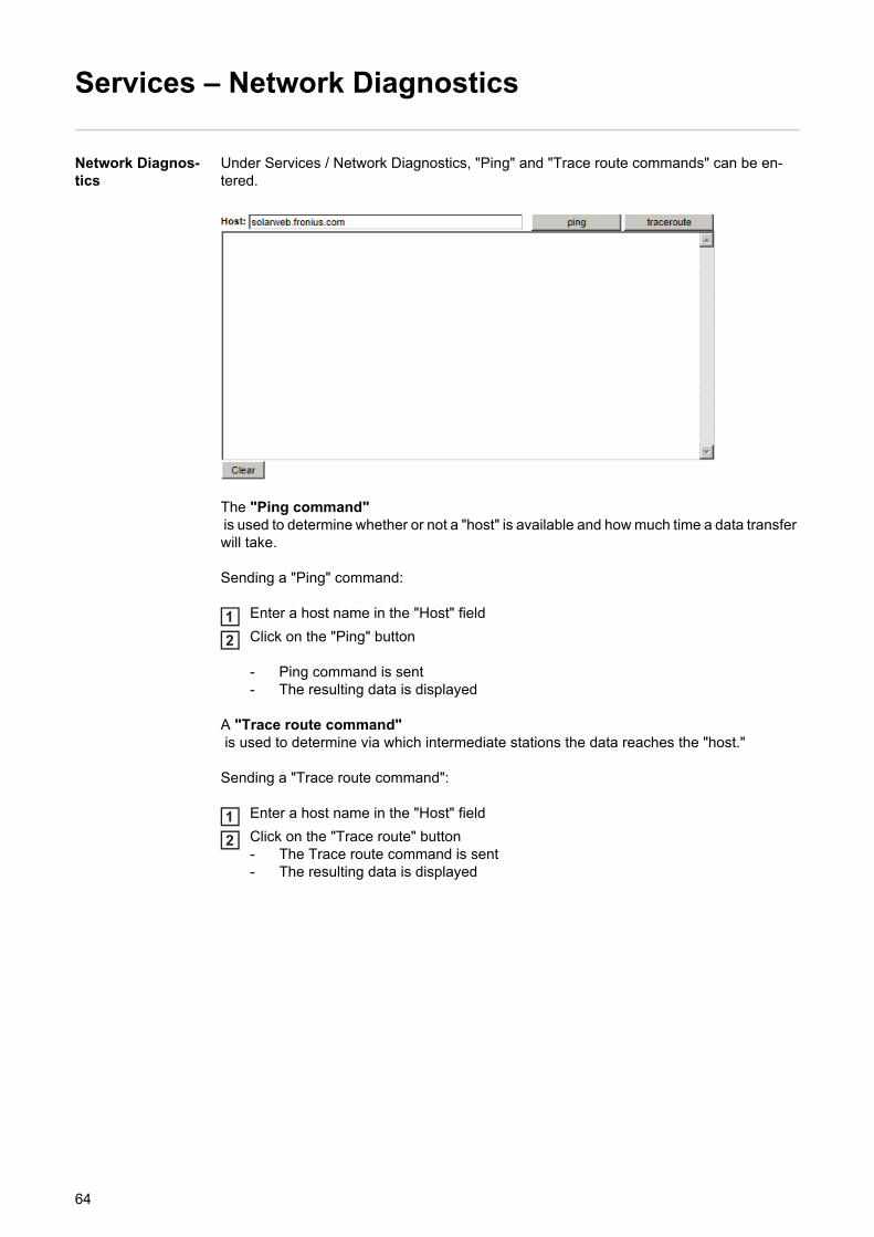
Under Services / Network Diagnostics, "Ping" and "Trace route commands" can be en-tered.
The "Ping command" is used to determine whether or not a "host" is available and how much time a data transfer will take.
Sending a "Ping" command:
Enter a host name in the "Host" field
Click on the "Ping" button
- Ping command is sent- The resulting data is displayed
A "Trace route command" is used to determine via which intermediate stations the data reaches the "host."
Sending a "Trace route command":
Enter a host name in the "Host" field
Click on the "Trace route" button- The Trace route command is sent- The resulting data is displayed
12
12
64

EN
-US
Services – Firmware Update
General You can update the Fronius Datamanager firmware under Services / Firmware Update. A "firmware update" can be performed via LAN or web.
Automatic Update Search
When the "Automatic update search" option (1) is activated, Fronius Datamanager will au-tomatically search for updates once a day. If new updates are available, these are dis-played at the bottom of the Fronius Datamanager web interface.
(1)
65

Manual update search
When the "Automatic update search" function is deactivated, there will be no automatic up-date search.
To search manually for updates, use the "Check now" button (3) 1
(3)
66

EN
-US
Firmware update via web
Procedure:
Use your internet browser to open the Fronius Datamanager web interface
Open Settings/Firmware update
Click on the "Run update" button
If the connection to the server fails:- Deactivate the firewall for the duration of the update- Retry the update
IMPORTANT! If a proxy server is used to connect to the Internet:- The ‘Use proxy server for Web update’ selection option must be activated- The required data must be entered
NOTE! The update process can take several minutes. The power supply to Fro-nius Datamanager and the internet connection should not be disconnected during this time. The web interface and the connection to Fronius Solar.access or Fro-nius Solar.web will not be available during the update process.
The update is complete when the "Supply LED" lights up green.
123
67
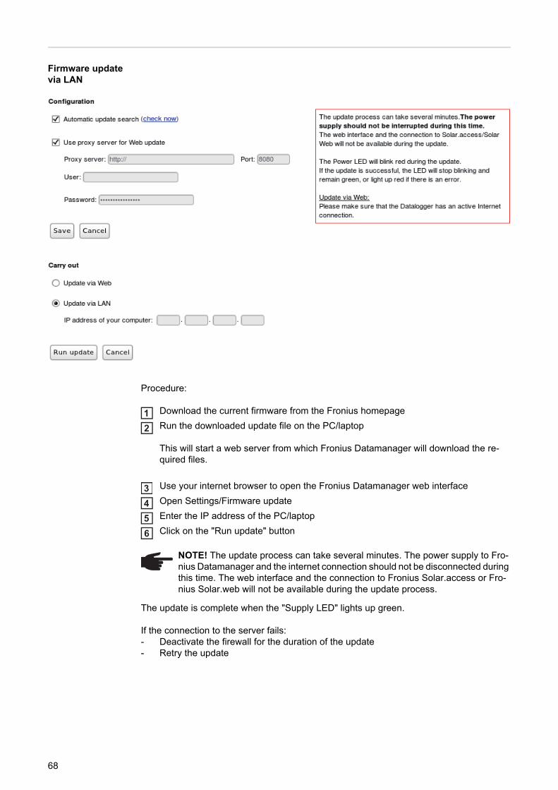
Firmware update via LAN
Procedure:
Download the current firmware from the Fronius homepage
Run the downloaded update file on the PC/laptop
This will start a web server from which Fronius Datamanager will download the re-quired files.
Use your internet browser to open the Fronius Datamanager web interface
Open Settings/Firmware update
Enter the IP address of the PC/laptop
Click on the "Run update" button
The update is complete when the "Supply LED" lights up green.
If the connection to the server fails:- Deactivate the firewall for the duration of the update- Retry the update
NOTE! The update process can take several minutes. The power supply to Fro-nius Datamanager and the internet connection should not be disconnected during this time. The web interface and the connection to Fronius Solar.access or Fro-nius Solar.web will not be available during the update process.
12
3456
68

Fronius Datamanager Settings

EN
-US
Settings – Passwords
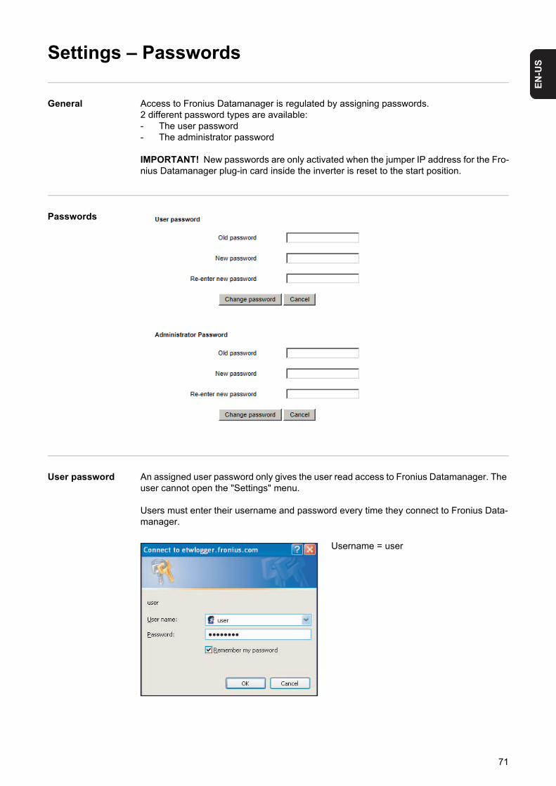
General Access to Fronius Datamanager is regulated by assigning passwords.2 different password types are available:- The user password- The administrator password
IMPORTANT! New passwords are only activated when the jumper IP address for the Fro-nius Datamanager plug-in card inside the inverter is reset to the start position.
Passwords
User password An assigned user password only gives the user read access to Fronius Datamanager. The user cannot open the "Settings" menu.
Users must enter their username and password every time they connect to Fronius Data-manager.
Username = user
71

Administrator Password
An assigned administrator password gives the user both read and write access to Fronius Datamanager. The user can then open the "Settings" menu and make any changes as de-sired.
When assigning an administrator password, the user must enter the username and pass-word in Fronius Datamanager to open the "Settings" menu.
Username = admin
Forgot Your Password?
Directly connect to Fronius Datamanager: - in accordance with chapter "Fronius Datamanager network configuration"- in accordance with section "Starting up Fronius Datamanager and opening the
Fronius Datamanager web interface"
The Fronius Datamanager web interface will appear (no request for passwords)
Enter new passwords
1
2
72

EN
-US
Settings – Time/Date
General The date and time have several tasks in the system. The time and date are saved for every data record that is logged.
Time/Date
(1) Time display
(2) Date display
(3) Time zone
(4) Time/Date setting option: synchronize to PC/laptop or manual
(5) Automatically adjust for daylight saving time
NOTE! You must set the time and date in order to operate Fronius Datamanager. Data can only be logged if the time and date are set.
(1) (2) (3)
(4) (5)
(6) (7)
(10)
(8)
(9)
(1) (2)(3)
(4) (5)
(6)(7) (8)
(9) (10)(9)
11 03 2009
(7a)
(7b)
73

IMPORTANT! For the automatic daylight saving time setting, the correct time zone must be selected.
(6) Time from PC/laptop for PC synchronization setting Field for manually setting the time
(7) Date from PC/laptop for PC synchronization setting
(7a) Calendar icon
(7b) Calendar (opens when you click on the calendar icon)
(8) Field for setting the time zone
(9) "Synchronization" button
(10) "Cancel" button
74

EN
-US
Settings – General
General
You can enter the charge rate per kWh and the currency for calculating the yield in "Yield" (1). The yield is shown in the current Total View.
You can enter the CO2 savings per kWh and the unit for calculating the CO2 savings in CO2 factor (2). The CO2 savings are shown in the current Total View.
(1)
(2)
75
Settings – Inverter
Views – Inverter
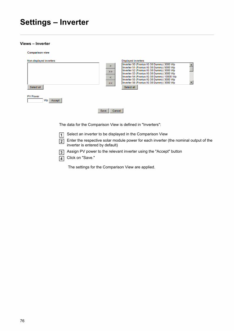
The data for the Comparison View is defined in "Inverters":
Select an inverter to be displayed in the Comparison View
Enter the respective solar module power for each inverter (the nominal output of the inverter is entered by default)
Assign PV power to the relevant inverter using the "Accept" button
Click on "Save."
The settings for the Comparison View are applied.
12
34
76

EN
-US
Settings – Sensor Cards
Sensor Cards
A specific channel name can be assigned to each sensor value of a Sensor Card in "Sen-sor Cards" (e.g., Wind Speed)
Select Sensor Card for which the channel names are to be changed
Enter the desired channel names
Click on "Save"
The settings for the Total View are applied.
123
77

Settings – Logging
General At regular intervals, Fronius Datamanager saves the real-time data of all inverters as well as all sensor cards and Fronius sensor boxes integrated into the system. The save interval can be defined in a range of 5 - 30 minutes.
The data can be easily edited, archived, and viewed with a PC or laptop using the "Fronius Solar.access" software.
Logging
Memory capacity Fronius Datamanager has a memory capacity of up to 5 years and 7 months for a photo-voltaic system with one inverter and a save interval of 15 minutes.However, the memory capacity is reduced depending on the number of inverters and/or Fronius sensor cards/boxes that are integrated into the system.
Calculating mem-ory capacity
Determine logging points for inverters and Fronius sensor cards/boxes
Calculate the total logging points
Total logging points == (number of inverters x logging points per day) + (number of Fronius Sensor Cards/Boxes x logging points per day)
Determine memory sectors per day
Round to whole numbers
Determine memory capacity
Logging points per day =Logging duration [min]
Save interval [min]
Logging duration [min]- For inverter: e.g., 14 hours = 840 minutes- For Fronius Sensor Card/Fronius Sensor Box: 24 hours = 1440 minutes
Memory sectors per day =Total logging points
114
Memory capacity [days] =2048
Memory sectors per day
1
2
3
45
78

EN
-US
Calculation exam-ple
2 inverters, logging duration = 14 hours (840 minutes)1 Fronius Sensor Card, logging duration = 24 hours (1440 minutes)
Save interval = 15 minutes
1. Logging points per day:
2. Total logging points:
3. Memory sectors per day:
4. Rounded:
5. Memory capacity [days]:
Overwriting data when memory is full
When the Fronius Datamanager memory is full, the oldest data will be continually overwrit-ten by the newest data.
"Delete Data" but-ton
All log data saved to Fronius Datamanager is deleted using the "Delete Data" button.
IMPORTANT! The power supply to Fronius Datamanager must not be interrupted during the deletion process.
Inverter logging points =840 min
= 5615 min
Sensor Card logging points = 1440 min
= 9615 min
Total logging points = (2 x 56) + (1 x 96) = 208
(2 x 56) ... 2 inverters, (1 x 96) ... 1 Sensor Card
Memory sectors =208
= 1,825114
1,825 2
Memory capacity = 2048
= 1024 days (= 2 years, 9 months, 18 days)2
Memory capacity [days] =2048
Memory sectors per day
79
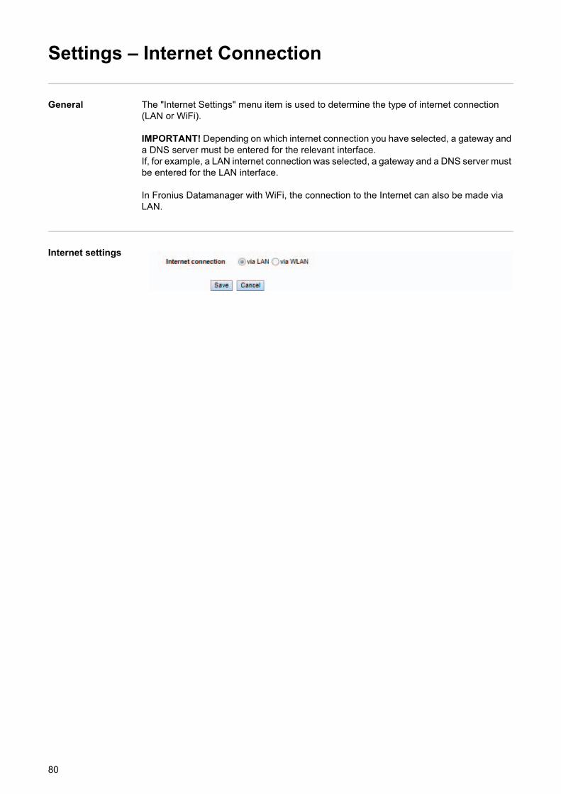
Settings – Internet Connection
General The "Internet Settings" menu item is used to determine the type of internet connection (LAN or WiFi).
IMPORTANT! Depending on which internet connection you have selected, a gateway and a DNS server must be entered for the relevant interface.If, for example, a LAN internet connection was selected, a gateway and a DNS server must be entered for the LAN interface.
In Fronius Datamanager with WiFi, the connection to the Internet can also be made via LAN.
Internet settings
80
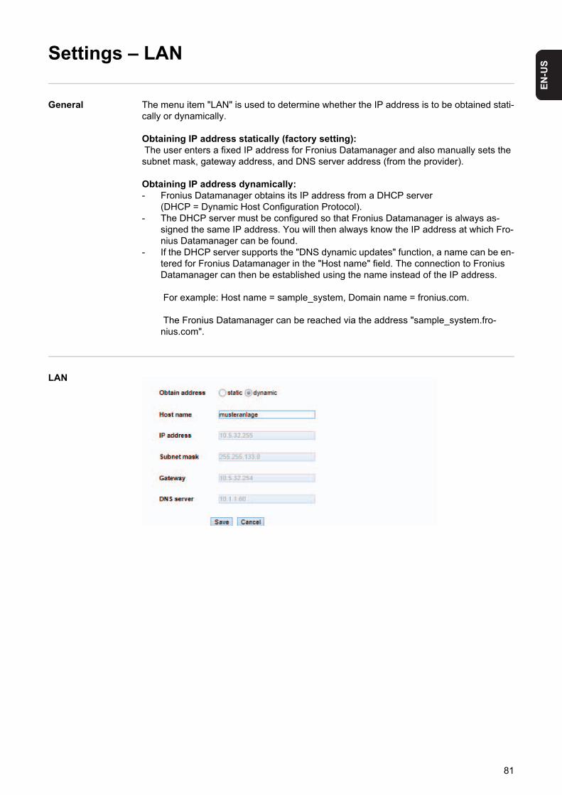
EN
-US
Settings – LAN
General The menu item "LAN" is used to determine whether the IP address is to be obtained stati-cally or dynamically.
Obtaining IP address statically (factory setting): The user enters a fixed IP address for Fronius Datamanager and also manually sets the subnet mask, gateway address, and DNS server address (from the provider).
Obtaining IP address dynamically:- Fronius Datamanager obtains its IP address from a DHCP server
(DHCP = Dynamic Host Configuration Protocol).- The DHCP server must be configured so that Fronius Datamanager is always as-
signed the same IP address. You will then always know the IP address at which Fro-nius Datamanager can be found.
- If the DHCP server supports the "DNS dynamic updates" function, a name can be en-tered for Fronius Datamanager in the "Host name" field. The connection to Fronius Datamanager can then be established using the name instead of the IP address.
For example: Host name = sample_system, Domain name = fronius.com.
The Fronius Datamanager can be reached via the address "sample_system.fro-nius.com".
LAN
81

Settings – WiFi
General The menu item "WiFi" is used to determine whether the IP address is to be obtained stat-ically or dynamically.
Obtaining IP address statically (factory setting): The user enters a fixed IP address for Fronius Datamanager and also manually sets the subnet mask, gateway address, and DNS server address (from the provider).
Obtaining IP address dynamically:- Fronius Datamanager obtains its IP address from a DHCP server
(DHCP = Dynamic Host Configuration Protocol).- The DHCP server must be configured so that Fronius Datamanager is always as-
signed the same IP address. You will then always know the IP address at which Fro-nius Datamanager can be found.
- If the DHCP server supports the "DNS dynamic updates" function, a name can be en-tered for Fronius Datamanager in the "Host name" field. The connection to Fronius Datamanager can then be established using the name instead of the IP address.
For example: Host name = sample_system, Domain name = fronius.com.
The Fronius Datamanager can be reached via the address "sample_system.fro-nius.com".
WiFi
82
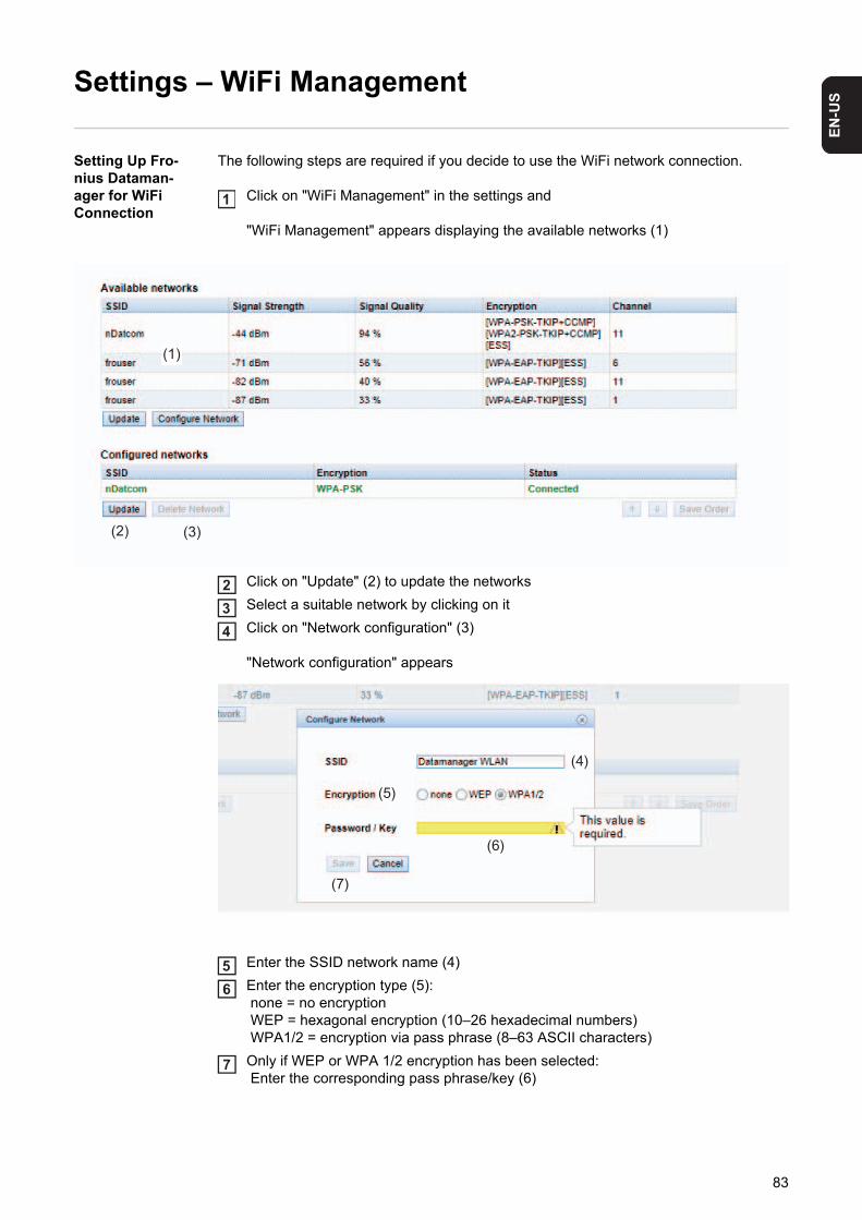
EN
-US
Settings – WiFi Management
Setting Up Fro-nius Dataman-ager for WiFi Connection
The following steps are required if you decide to use the WiFi network connection.
Click on "WiFi Management" in the settings and
"WiFi Management" appears displaying the available networks (1)
Click on "Update" (2) to update the networks
Select a suitable network by clicking on it
Click on "Network configuration" (3)
"Network configuration" appears
Enter the SSID network name (4)
Enter the encryption type (5): none = no encryption WEP = hexagonal encryption (10–26 hexadecimal numbers) WPA1/2 = encryption via pass phrase (8–63 ASCII characters)
Only if WEP or WPA 1/2 encryption has been selected: Enter the corresponding pass phrase/key (6)
1
(2) (3)
(1)
234
(4)
(6)
(7)
(5)
56
7
83

Click on "Save" (7)
After the changes have been loaded, the "Changes have been applied" message ap-pears
Click on "OK"
and "WiFi-Management" appears
You can use the arrow keys (8) and the "Save Order" key (9) to change the sequence of displayed networks.
(5)
(4)
(6)
(7)
8
9
(8) (9)
84

EN
-US
Settings – Solar.web
General The Solar.web menu item can be used to make a direct connection between Fronius Data-manager and Fronius Solar.web.
For more information about Fronius Solar.web, see:- http://www.fronius.com – in the Fronius Datamanager operating instructions, section
"Connecting to Fronius Datamanager via the Internet and Fronius Solar.web"- the Fronius Solar.web online help.
Solar.web
Daily data trans-mission to So-lar.web
If the ‘daily’ selection option is activated, you can select:- The time of day when data is transmitted (1)- Whether data is transmitted each day (2)- Whether data is transmitted only on specific days (3)
Hourly data trans-mission to So-lar.web
If the ‘hourly’ selection option is activated, you can select:- The times of day when data is transmitted (4)- Whether data is transmitted each day on the hour every hour (5)
(1) (2)
(3)(4) (5
85

Settings – Service Messages
General Service messages, inverter errors, the Fronius String Control, etc., are sent to Fronius Datamanager and saved. The "Service messages" selection option is used to define how service messages are communicated. They can be communicated via:- E-mail- Fax- SMS
Service messages can be analyzed further using Fronius Solar.web or Fronius Solar.ac-cess.
Service Messag-es
(1) System nameIncluded in the service message text;
IMPORTANT The system name is used to identify the photovoltaic system that sent the message. Always enter a system name.
(2) Selection field for the language in which the service message will be sent
(3) Message to e-mail recipientActivate to send service messages to one or more e-mail addresses
(4) Field for up to a max. of 10 e-mail addressesSeparate e-mail addresses with ";"
(5) Selection field to determine whether the service message will be sent immediately via e-mail or at a specific time
(6) Selection field for the time at which a service message will be sent via e-mail
(7) "Send test e-mail" button
(8) Message to fax recipientActivate to send service messages to a fax number
(1)
(2)
(3) (4) (5) (6) (7)
(22)
(20) (21)(19)(18)(17)(16)(15)
(14)(13)(12)(11)(10)(8)
(23)
(9)
86
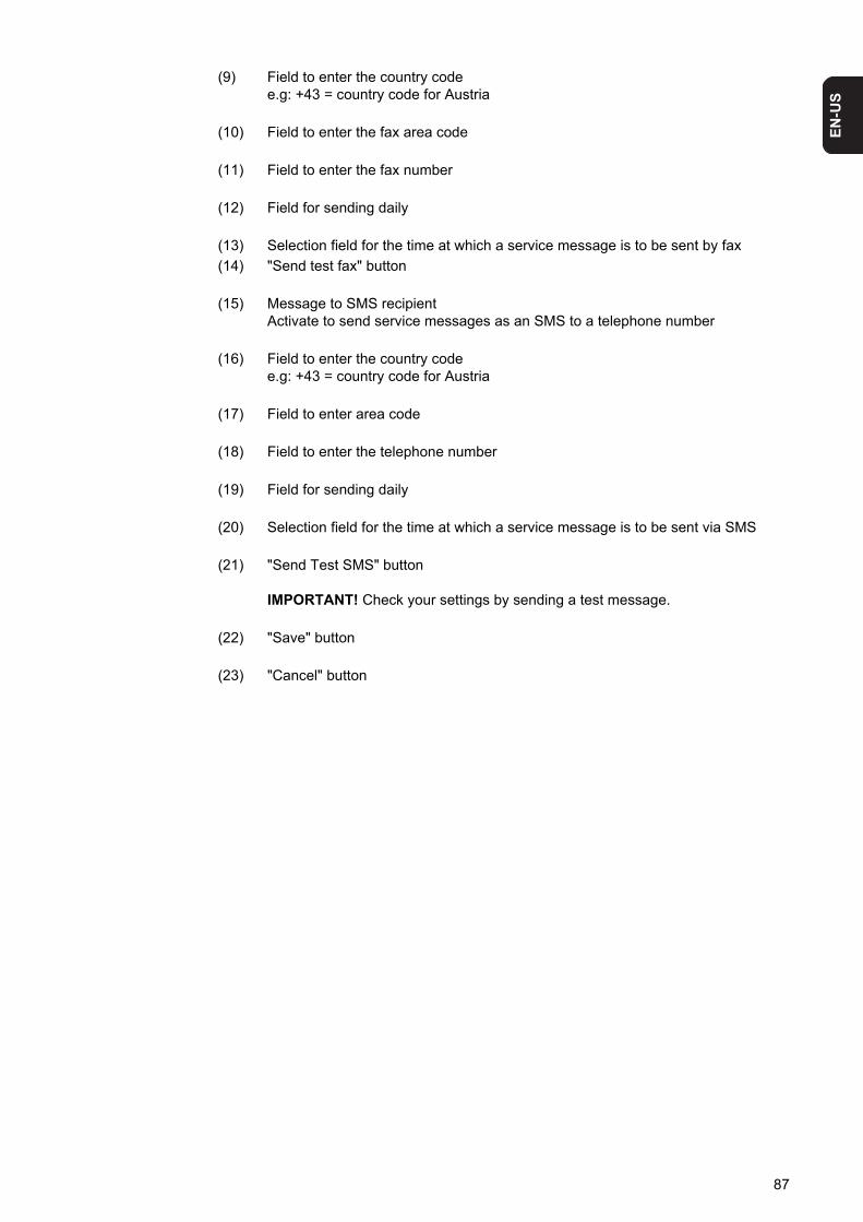
EN
-US
(9) Field to enter the country codee.g: +43 = country code for Austria
(10) Field to enter the fax area code
(11) Field to enter the fax number
(12) Field for sending daily
(13) Selection field for the time at which a service message is to be sent by fax
(14) "Send test fax" button
(15) Message to SMS recipientActivate to send service messages as an SMS to a telephone number
(16) Field to enter the country codee.g: +43 = country code for Austria
(17) Field to enter area code
(18) Field to enter the telephone number
(19) Field for sending daily
(20) Selection field for the time at which a service message is to be sent via SMS
(21) "Send Test SMS" button
IMPORTANT! Check your settings by sending a test message.
(22) "Save" button
(23) "Cancel" button
87

Settings – Energy Manager
General The output I/O 1 can be used to control an actuator (e.g., relay, contactor) via the "Energy Manager" function. A load connected to I/O 1 can thus be controlled by assigning a power feed-dependent switch-on or switch-off point.
Energy Manager
(1) Activating the rule
(2) Output I/O 1
(3) Switching threshold ONFor entering an effective power limit, at which the I/O 1 output is activated.
(4) Switching threshold OFFFor entering an effective power limit, at which the I/O 1 output is deactivated.
(5) Click "Reject" buttonto reject all changes and load the current Fronius Datamanager settings
(6) Click "Save" buttonto save changes
(1) (2)
(3) (4)(5)
(6)
88
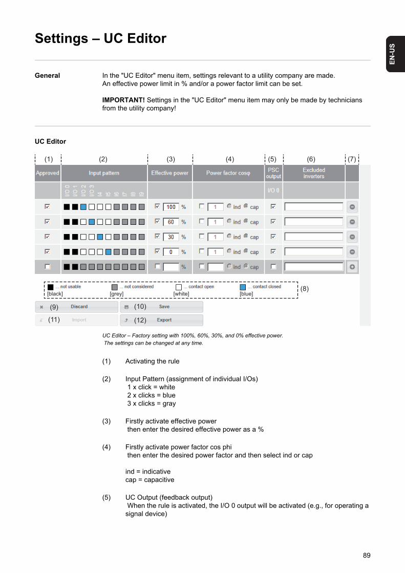
EN
-US
Settings – UC Editor
General In the "UC Editor" menu item, settings relevant to a utility company are made.An effective power limit in % and/or a power factor limit can be set.
IMPORTANT! Settings in the "UC Editor" menu item may only be made by technicians from the utility company!
UC Editor
UC Editor – Factory setting with 100%, 60%, 30%, and 0% effective power. The settings can be changed at any time.
(1) Activating the rule
(2) Input Pattern (assignment of individual I/Os) 1 x click = white 2 x clicks = blue 3 x clicks = gray
(3) Firstly activate effective power then enter the desired effective power as a %
(4) Firstly activate power factor cos phi then enter the desired power factor and then select ind or cap
ind = indicativecap = capacitive
(5) UC Output (feedback output) When the rule is activated, the I/O 0 output will be activated (e.g., for operating a signal device)
(1) (2) (3) (4) (5) (6) (7)
(12)(11)
(10)
(8)
(9)
[black] [grey] [white] [blue]
89

(6) Excluded inverters Enter the numbers of inverters here that are to be excluded from the control, sep-arating multiple inverters with commas
(7) Delete/Add a Rule + = add a new rule - = delete selected rule
(8) Legend for use of colors
(9) Click "Reject" buttonto reject all changes and load the current Fronius Datamanager settings
(10) Click "Save" button to save rules and changes
(11) Click "Import" button to import rules in *.fpc format;
the function of the "Import" button is dependent on the browser used, e.g., Firefox and Google Chrome support the function
(12) Click "Export" button to save the rules separately in *.fpc format
Connection Ex-ample
(1) Ripple control signal receiver with 3 relays for effective power limitation
(2) Ripple control signal receiver with 3 relays for power factor limitation
(3) I/Os on Fronius Datamanager
(4) Loads (e.g., signal light, signal relay)
The ripple control signal receiver and the Fronius Datamanager plug are connected to one another using a 4-pin cable in accordance with the connection diagram. For distances of greater than 10 m between Fronius Datamanager and the ripple control signal receiver, a shielded cable is recommended.
Uint / UextGNDI/O 0I/O 1I/O 2I/O 3I4I5I6I7I8I9
60 %
30 %
0 %
0,9
0,8
0,7
(1)
(2)
(3)
(4)
90
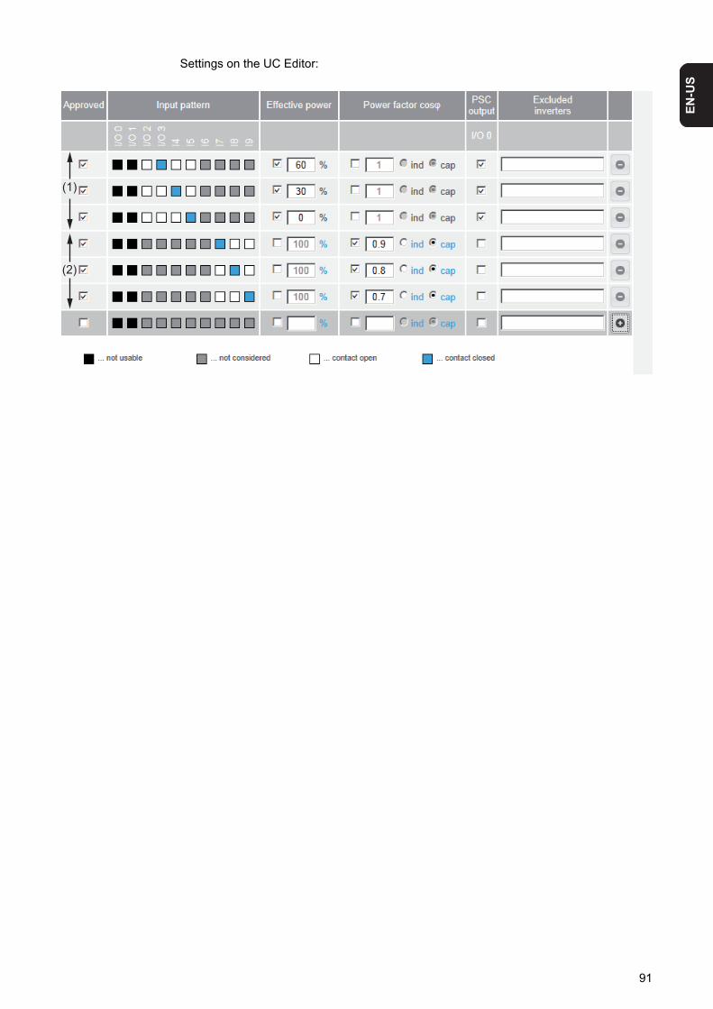
EN
-US
Settings on the UC Editor:
(1)
(2)
91

92

Appendix


EN
-US
Technical data
Technical Data
* When sufficient power is coming from Fronius Solar Net, the green LED lights up on every DATCOM component. If the green LED does not light up, the power pack available from Fronius should be inserted into the 12 V power pack connection socket of the DATCOM compo-nent. Check the cable and plug connections if necessary.
Memory capacity 16 MB
Supply voltage 230 V AC
Energy consumption typ. 1.4 W (without WiFi) typ. 2.2 W (with WiFi)
Dimensions 132 x 103 x 22 mm 5.2 x 4.1 x 0.9 in.
Ethernet (LAN) RJ 45, 100 MB
WiFi IEEE 802.11b/g Client
RS 485 (Fronius Solar Net) RJ 45
Ambient temperature -20 – +65°C -4 – +149°F
Solar Net power approx. 3 W max. 3 DATCOM components *
I/O Connection Specifications
Voltage level of digital inputs low = min. 0 V – max. 1.8 V high = min. 3 V – max. 30 V
Input currents of digital inputs depending on the input voltage; input resistance = 46 kOhm
Switching capacity of digital outputs when supplied by the Datamanager plug-in card
3.2 W, 10.7 Vin total for all 4 digital outputs
(minus other Solar Net participants)
Switching capacity of digital outputs when supplied by an external power supply with min. 10.7 – max. 24 V DC
1 A, 10.7 – 24 V DC (depending on the external power supply)
per digital output
Max. switchable energy of digital outputs 76 mJ (per output)
95

Fronius Worldwide - www.fronius.com/addresses
Under http://www.fronius.com/addresses you will find all addresses of our sales branches and partner firms!
Fronius International GmbH4600 Wels, Froniusplatz 1, AustriaE-Mail: [email protected]://www.fronius.com
Fronius USA LLC Solar Electronics Division6797 Fronius Drive, Portage, IN 46368E-Mail: [email protected]://www.fronius-usa.com