
Operating instructions - Schlüsselbauersupport.sbm.at/download/TR/AMA/EX/doc/StandardParts/Seilzug...
56
720 IS 813 211 055 44 190608 enEN Operating instructions Demag DR Pro rope hoist Foot-mounted hoist FDR 3 - FDR 5 - FDR 10 42382544.eps
Transcript of Operating instructions - Schlüsselbauersupport.sbm.at/download/TR/AMA/EX/doc/StandardParts/Seilzug...

720 IS 813211 055 44190608 enEN
Operating instructionsDemag DR Pro rope hoistFoot-mounted hoist FDR 3 - FDR 5 - FDR 10
42382544.eps

2 2110
5544
.indd
/190
608
Manufacturer Demag Cranes & Components GmbHP.O. Box 67, D-58286 WetterTelephone +49 (0) 2335 92-0 · Telefax +49 (0) 2335 927676www.demagcranes.com
Please fill in the following table before first putting the unit into service.This provides you with a definitive documentation of your Demag rope hoist and important information if you ever have to contact the manufacturer or his repre-sentative.
Owner
Where in use
Range
Serial number
Main hoist motor number
Operating voltage
Control voltage
Frequency
Wiring diagram number
Accompanying documents
Operating instructions
DSE-R control pendant 214 940 44 720 IS 975
DRC-10 radio remote control systems 214 920 44 720 IS 975
DRC-J radio remote control systems 214 975 44 720 IS 975
Spare parts list
Demag rope hoist FDR Pro 3 217 032 44 721 IS 813
Demag rope hoist FDR Pro 5 217 036 44 721 IS 813
Demag rope hoist FDR Pro 10 217 042 44 721 IS 813
Technical data
Demag FDR Pro rope hoist 203 675 44 714 IS 813
Test and inspection booklet for cranes and hoist units 206 124 44 720 IS 100

32110
5544
.indd
/190
608
Contents
0 Foreword 50.1 Copyright 50.2 Customer service 50.3 Liability for defects 60.4 Limitations of liability 60.5 Definitions 7
1 Safety instructions 81.1 Symbols 81.2 Intended use 81.3 Prohibited practices 91.4 Basic information on safety 91.5 Selection and qualification of operating and maintenance personnel 101.6 Safety instructions for assembly and disassembly 111.7 Safety instructions when first putting the unit into service
after completing installation 111.8 Safety instructions for operation 111.9 Safety instructions for maintenance 12
2 Technical data 142.1 Design overview / type assignment 142.2 Explanation of size designation / type assignment 142.3 Selection criteria 152.4 Selection table 162.5 Hoist motor data 172.6 Motor data for DR 3 – 10 for inverter operation 192.7 Mounting positions A/B 212.8 Gearbox oil filling 212.9 Setting hook dimension C 22
3 General 233.1 Inspection regulations 233.2 Hoist units operating outdoors 233.3 Packing and storage 233.4 Paint finish 233.5 Operating conditions 233.6 Noise emission measurement according to DIN 45635 24
4 Description 254.1 Design 254.2 Drive 254.3 Gearbox/rope reeving components 254.4 Arrangement of assemblies 264.5 Geared limit switch 264.6 Integrated controls 264.7 Inverter housing 264.8 DSE-10R control pendant 264.9 Overload protective devices for Demag rope hoists 26
5 Installing the rope hoist 275.1 Hoist unit attachment 275.2 FDR 3 - 10 hoist bore hole templates 285.3 FDR 5 - 10 H30; H40 bracket mounting bore hole template 29

4 2110
5544
.indd
/190
608
6 Connection of the electrical equipment 306.1 Electrical equipment 306.2 Mains connection and control signal 306.3 Checking the direction of movement 316.4 Control system 326.5 Control pendant 33
7 Rope reeving 347.1 Reeving methods 347.2 Reeving methods for the rope hoist 34
8 Putting into operation 388.1 Geared limit switch 388.1.1 Determining the switch-off points for the geared limit switch 388.2 Setting geared limit switches 398.3 125 % overload for the acceptance test 408.4 Inspection before putting the unit into operation 408.5 Instructions relating to safety at work 408.6 Starting operation 40
9 Taking the unit out of service at the end of the shift/for maintenance 41
9.1 Emergency stop 419.2 Taking the unit out of service at the end of the shift 419.3 Taking the unit out of service for maintenance purposes 41
10 Inspections/maintenance/general overhaul GO 4210.1 Inspection before starting work and during operation 4210.2 Inspection and maintenance schedule 4210.3 General overhaul GO 4210.4 Discarding the wire rope 4410.5 Wire ropes 4510.5.1 Construction, application and reeving of wire ropes 4510.6 Wear limits on rope sheaves 4610.7 Fitting the wire rope and rope guide 4710.7.3 Shortening the wire rope 5010.7.4 Lubricating the wire rope 5010.8 Regular inspections and monitoring measures for load hooks 51
11 Calculating the actual duration of service 5212 Finding faults 53

52110
5544
.indd
/190
608
0 Foreword
You have purchased a Demag product. This Demag rope hoist was manufactured in accordance with the applicable Euro-pean standards and regulations. The rope hoist complies with the statutory regulations e.g. EC directive 98/37/EC.
Demag rope hoists are of modular design.The main assemblies include:• Gearboxes• Hoist motor• Integrated electrics• Rope reeving components• Control pendantThese operating instructions are designed to provide the owner with appropriate instructions for safe and correct operation and for maintenance.Every individual given the task of transporting, installing, commissioning, operat-ing, maintaining and repairing our rope hoists and additional equipment must have read and understood• the operating instructions• the safety regulations and • the safety instructions in the individual chapters and sections.The operating instructions must be available to the operating personnel at all times in order to prevent operating errors and to ensure smooth and trouble-free opera-tion of our products.
These operating instructions must be treated confidentially. They should only be used by authorized personnel. They may only be entrusted or made available to third parties with the prior written consent of Demag. All documents are protected within the sense of copyright law.No part of this documentation may be reproduced, utilized or transmitted without specific prior consent. Infringements are an offence resulting in obligatory compen-satory damages. All industrial rights reserved.
Our after-sales service will provide you with all technical information on Demag products and their systematic application. Should you have any questions regarding our products, please refer to one of our after-sales service centres, the relevant representative or the head office in Wetter.Kindly quote the serial or order number (see test and inspection booklet, load ca-pacity plate on the crane) in any correspondence or for spare part orders. Specifying this data ensures that you receive the correct information or the re-quired spare parts.The relevant after-sales service station of Demag is specified for example on the back page of the rope hoist test and inspection booklet.
0.1 Copyright
0.2 Customer service
6 2110
5544
.indd
/190
608
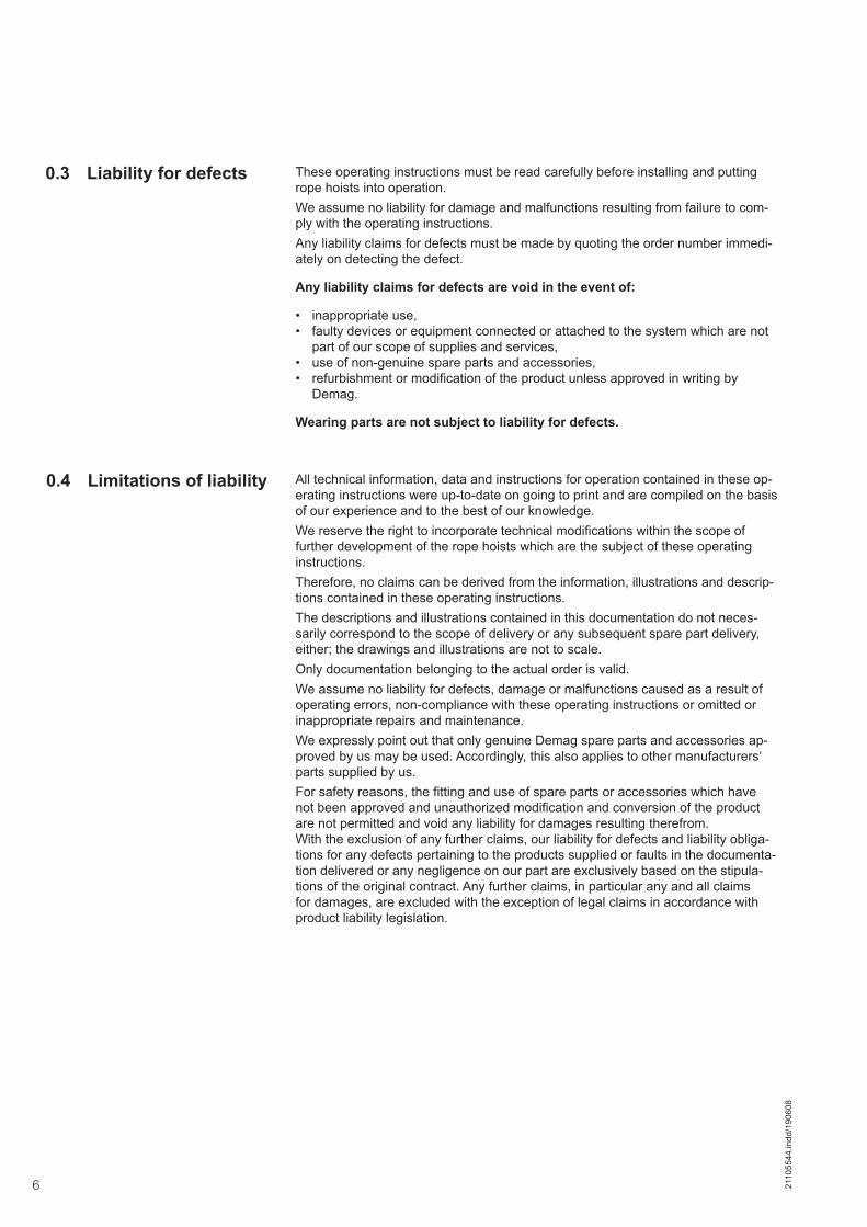
These operating instructions must be read carefully before installing and putting rope hoists into operation.We assume no liability for damage and malfunctions resulting from failure to com-ply with the operating instructions.Any liability claims for defects must be made by quoting the order number immedi-ately on detecting the defect.
Any liability claims for defects are void in the event of:
• inappropriate use,• faulty devices or equipment connected or attached to the system which are not
part of our scope of supplies and services,• use of non-genuine spare parts and accessories,• refurbishment or modification of the product unless approved in writing by
Demag.
Wearing parts are not subject to liability for defects.
All technical information, data and instructions for operation contained in these op-erating instructions were up-to-date on going to print and are compiled on the basis of our experience and to the best of our knowledge.We reserve the right to incorporate technical modifications within the scope of further development of the rope hoists which are the subject of these operating instructions. Therefore, no claims can be derived from the information, illustrations and descrip-tions contained in these operating instructions.The descriptions and illustrations contained in this documentation do not neces-sarily correspond to the scope of delivery or any subsequent spare part delivery, either; the drawings and illustrations are not to scale.Only documentation belonging to the actual order is valid.We assume no liability for defects, damage or malfunctions caused as a result of operating errors, non-compliance with these operating instructions or omitted or inappropriate repairs and maintenance. We expressly point out that only genuine Demag spare parts and accessories ap-proved by us may be used. Accordingly, this also applies to other manufacturers‘ parts supplied by us.For safety reasons, the fitting and use of spare parts or accessories which have not been approved and unauthorized modification and conversion of the product are not permitted and void any liability for damages resulting therefrom. With the exclusion of any further claims, our liability for defects and liability obliga-tions for any defects pertaining to the products supplied or faults in the documenta-tion delivered or any negligence on our part are exclusively based on the stipula-tions of the original contract. Any further claims, in particular any and all claims for damages, are excluded with the exception of legal claims in accordance with product liability legislation.
0.3 Liability for defects
0.4 Limitations of liability

72110
5544
.indd
/190
608
0.5 Definitions OwnerOwners (employer, company) are defined as persons who own the rope hoist and who use it appropriately or allow it to be operated by suitable and trained persons.
Operating personnel/operatorOperating personnel or operators are defined as persons entrusted by the owner of the rope hoist with operation of the equipment.
Specialist personnelSpecialist personnel are defined as persons assigned by the owner of the rope hoist to carry out special tasks such as installation, setting-up, maintenance and fault elimination.
Qualified electricianQualified electricians are defined as persons who, owing to their technical training, knowledge and experience of electrical installations as well as knowledge of the relevant standards, codes of practice and regulations, are able to assess the tasks given to them and to identify and eliminate potential hazards.
Trained personTrained persons are defined as persons who have been instructed and trained for the tasks assigned to them and on the possible hazards resulting from incor-rect handling and who have been informed about the required protective devices, protective measures, relevant regulations, codes of practice, accident prevention regulations and operating conditions and who have proven their qualifications.
Experienced technicianExperienced technicians are defined as persons, who, owing to their technical training and experience, have sufficient knowledge of rope hoists and are familiar with the relevant national industrial safety regulations, codes of practice, accident prevention regulations, directives and generally accepted engineering standards enabling them to judge the safe operating condition of rope hoists.
Assigned expert engineer (in the Federal Republic of Germany according to BGV 8, § 23, for determining the S.W.P.) An assigned expert engineer is defined as an experienced technician specifically assigned by the manufacturer to determine the remaining duration of service (serv-ice life) of rope hoists (S.W.P. = safe working period) and to carry out a general overhaul of rope hoists.
Authorized expert engineer (according to BGV 9, § 28) In addition to the expert engineers of the Technical Supervisory and Inspection Board, an authorized expert engineer for the inspection of rope hoists is defined as an expert engineer authorized by the Industrial Employers’ Mutual Insurance As-sociation.
Rope hoistsRope hoists are systems used for lifting and moving loads, such as cranes, crabs and travelling hoist units, rail systems.

8 2110
5544
.indd
/190
608
1 Safety instructions
1.1 Symbols The following symbols and instructions warn against possible personal injuries or damage to property and are intended to assist you in your work.
Hazard warningThis symbol appears in the operating instructions next to all instructions relating to safety at work wherever a potential hazard to life and limb exists if the instructions are not complied with.Follow these instructions at all times and be particularly careful and cautious.Pass on safety instructions to all persons entrusted with working on the rope hoist including the track and power supply.In addition to the safety instructions, observe all general safety regulations and fac-tory accident prevention regulations at all times.
Warning against electrical hazardsContact with live parts can result in immediate death. Protective covers (e.g. cov-ers and enclosures) marked with this sign may only be opened by qualified electri-cians. Before opening, all relevant operating, control, feed or other voltages must be disconnected.
Warning against suspended loadAny person remaining in this danger zone may suffer serious injury or death. The load must not be transported above persons when using load handling attach-ments which retain the load by means of magnet, friction or suction forces without an additional load securing device. In each case the special safety and operating instructions contained in the operating instructions for the load handling attach-ment in question must be complied with.
Operating hazard for the installationThis symbol indicates information on the appropriate use of machinery. In the oper-ating instructions, it indicates all warnings which, if not complied with, may result in damage to the rope hoist or the load.
Rope hoists are only intended for lifting, lowering and moving loads and may be used as stationary or travelling units.Rope hoists may only be operated when in perfect working order by trained personnel in accordance with the relevant safety and accident prevention regulations. This also includes compliance with operating and maintenance conditions specified in the operating instructions.Rope hoists can be operated with a rated voltage of up to 480 V.Power is fed via power supply lines (mobile cables, open or enclosed power con-ductor systems, cable drums). These systems are live up to the terminals of the main switch (mains connection switch, isolating switch).The relevant main switches must be switched off and secured when carrying out maintenance/repair work. During operation or when the main switch is not switched off, electrical components inside enclosures, motors, switchgear cabi-nets, load handling attachments, terminal boxes, etc., carry dangerous voltages. This voltage may cause fatal injuries.
The theoretical duration of service (to ISO 4301/FEM 9.755) in connection with the actual mode of operation (see 2.3 Selection criteria) results in the safe working period S.W.P.
1.2 Intended use
Design limit

92110
5544
.indd
/190
608
1.3 Prohibited practices
Any failure to comply with these instructions causes danger to life and limb in the event of:• unauthorized removal of covers,• inappropriate use of the rope hoist,• incorrect operation,• insufficient maintenance,• exceeding the maximum permitted load. The rated safe working load is the maximum permitted load. Pay attention to the
sum of the load to be lifted and the load handling attachment.• working on live parts.
Advise operators to avoid inching as far as possible. It may cause excessive wear and premature failure of the rope hoist. Inching means giving short pulses to the motor to obtain small movements, e.g. when lifting loads or moving the travelling hoist unit or the crane.
Certain work and practices are prohibited when using the rope hoist as they may involve danger to life and limb and result in lasting damage to the rope hoist, e.g.:• Do not handle the load in an unsafe manner (e.g. swinging the load).• Do not handle suspended loads above persons.• Do not pull or drag suspended loads at an angle.• Pulling free fixed or obstructed loads.• Exceeding the maximum permitted load.• Do not leave suspended loads unsupervised.• Allowing ropes to run over edges.• Using the rope as a load bearing sling.• Allowing loads to drop when the rope is in a slack condition.• Do not subject the control switch to inappropriate mechanical loads.• Transporting persons with the hoist unit is not permitted unless hoist units are
specifically approved for transporting persons.• Manipulating electrical equipment.• Lifting the load with a slack rope.• Lifting the load at full speed.
Persons under the influence of drugs, alcohol or medicines which affect reactions must not install, put into service, operate, maintain, repair or disassemble the rope hoist.Any conversions and modifications to the installation require the written consent of Demag.Work on electrical equipment of rope hoists may only be carried out by qualified electricians in accordance with electrical regulations. Rope hoists must be taken out of service immediately and the relevant main switch must be switched off in the event of any malfunctions. Malfunctions must be eliminated immediately.National accident prevention regulations and codes of practice and general safety regulations must be observed when operating our products. Important information and instructions are marked by corresponding symbols.Follow these instructions and/or safety regulations in order to avoid accidents and damage. The operating instructions must be kept available at the place where the rope hoist is in use at all times. They include significant aspects and appropriate excerpts from the relevant guidelines, standards and regulations. The owner must instruct his personnel accordingly.If the safety instructions given in these operating instructions are not observed in any way, personal injury or even death can result.
1.4 Basic information on safety

10 2110
5544
.indd
/190
608
Observe general statutory and other obligatory regulations relating to accident prevention and environmental protection and basic health and safety requirements in addition to those included in these operating instructions. Such requirements may also relate, for example, to the handling of hazardous materials or the provi-sion/wearing of personal protection equipment. Comply with these regulations and general accident prevention regulations relevant for the place at which the rope hoist is used and follow the instructions therein when working with the rope hoist. The rope hoist may still constitute a danger to life and limb if it is not installed, operated, maintained or used appropriately by personnel which have not been trained or specially instructed. The operating instructions must, if required, be sup-plemented by the owner with instructions and information (e.g. factory regulations) relating to organization of work, working procedures, operating personnel, etc. Supervising and reporting obligations as well as special operating conditions must also be taken into consideration. Personnel assigned to working with the rope hoist must have read and understood the operating instructions and, in particular, the chapter on safety information. All activities relating to rope hoists which are not described in these operating instruc-tions may only be carried out by specifically trained specialist personnel. The owner must ensure that personnel work in a safety and hazard-conscious manner in compliance with the operating instructions. The owner must ensure that the rope hoist is only operated when in proper work-ing order and that all relevant safety requirements and regulations are complied with.Rope hoists must be taken out of service immediately if functional defects or irreg-ularities are detected. In the event of a stoppage (e.g. if defects regarding safe and reliable operation are detected, in emergency situations, in the event of operating malfunctions, for repairs and maintenance purposes, if damage is detected or after finishing work), the operator/experienced technician must carry out all prescribed safety measures. Personal protective clothing must be worn as necessary or as required by regula-tions. Personnel must not wear any loose clothing, jewellery including rings or long hair loose. Injury may occur, for example, by being caught or drawn into the mechanism. All safety and hazard information on the rope hoist, at access points and mains connection switches must be maintained in complete and legible condition.Inching (i.e. giving short pulses to the motor) must always be avoided. Emergency limit stop devices (e.g. slipping clutch or emergency limit switch) must not be ap-proached in normal operation.Modifications, additions to and conversions of the rope hoist which may impair safety in any way must not be carried out without the written consent of Demag. This also applies to the subsequent installation of safety devices as well as for performing welds on load bearing parts. Safety devices must not be rendered inop-erative.Only genuine Demag spare parts and accessories may be used. Observe pre-scribed deadlines or those specified in the operating instructions for routine checks/inspections.
For independent operation or maintenance of the rope hoist, the owner may only employ persons• who are at least 18 years of age,• who are mentally and physically suitable,• who have been instructed in the operation or maintenance of the rope hoist and
have proven their qualification to the owner in this respect (in addition to theo-retical training, instruction also includes sufficient practical operating experience as well as acquiring the ability to identify defects which are a hazard to safe operation),
• who can be expected to carry out the work assigned to them reliably.The owner must assign operating and maintenance personnel to their relevant tasks.
1.5 Selection and quali-fication of operating and maintenance personnel

112110
5544
.indd
/190
608
• Installation and disassembly work may only be performed by experienced tech-nicians.
• Installation and disassembly work must be co-ordinated by the person carrying out the work and the owner within the scope of their responsibility.
• The working and danger zone must be made safe.• The installation must be isolated in accordance with the relevant electrical regu-
lations.• Customer-specific regulations must be observed.• Only appropriate, tested and calibrated tools and equipment may be used.• The electrode holder and earth must be connected to the same assembly when
welding work is carried out (if the current flow is returned via protective con-ductors, screening elements or anti-friction bearings, serious damage may be caused to these or other components).
• The Demag rope hoist must be attached at the appropriate connecting points.
• The working and/or danger zone must be made safe.• First check that the voltage and frequency specified on the data plates match
the owner‘s mains power supply.• All clearance dimensions and safety distances (see approval drawing) must be
checked before putting the unit into service.• When putting the unit into service, it may be necessary to perform work in the
danger zone.• In the course of putting the unit into service, it may be necessary to temporarily
render safety devices or features inoperative.• It must be ensured that only trained personnel are employed for putting the unit
into service.
The operator must check the function of the brakes and emergency limit stop and emergency stop devices before starting work.All instructions and measures described in the operating instructions with regard to safe operation and items concerning general safety and accident prevention which have to be observed before, during and after the product is put into service must be strictly complied with. Any failure to comply can lead to accidents resulting in fatalities.Rope hoists must be taken out of service immediately or not put into operation if any defects relating to operating safety and reliability are detected.Safety devices must not be rendered inoperative or modified in contradiction to their intended use.Only operate rope hoists when all protective devices and safety-relevant equip-ment, e.g. movable protective devices and emergency-stop devices, are fitted and fully functioning.Anybody who identifies an immediate danger of personal injury must actuate the emergency stop button without delay. This also applies in the case of damage oc-curring to parts of the installation and equipment which makes immediate stoppage necessary.After an emergency-stop, the operator must not switch on and restart the rope hoist until an experienced technician is satisfied that the cause which led to actua-tion of this function has been rectified and that continued operation of the installa-tion constitutes no further hazard.Rope hoists must be switched off immediately in the event of the following faults:• Damage to electrical devices and cables as well as parts of the insulation.• Brake and safety device failure.• If the lifting motion is switched off during lifting of the load, this may indicate trig-
gering of the overload protection device. In this case, the lifting motion must be interrupted and a lifted load must be set down immediately.
1.7 Safety instructions when first putting the unit into service after completing installation
1.8 Safety instructions for operation
1.6 Safety instructions for assembly and disassembly

12 2110
5544
.indd
/190
608
1.9 Safety instructions for maintenance
Ensure that nobody is endangered by operation of the rope hoist before switching it on or putting it into operation.If the operator notices persons who may be exposed to a risk to health or personal safety by operation of the equipment, he must suspend operation immediately and may not resume operation again until the persons are outside the danger zone.Before putting the rope hoist into operation, the operator must be satisfied that the rope hoist is in safe and correct operating condition.Work on rope hoists may only be carried out when instructions to this effect have been issued, when operation and function of the rope hoists have been explained and when the working and danger zone has been made safe. Cooling devices, such as ventilation openings, may not be rendered permanently inoperative (e.g. covered or closed).Special local conditions or special applications can lead to situations which were not known when these operating instructions were written. In such cases, special safety measures must be implemented by the owner.
Maintenance measures are defined as regular maintenance, inspection and repair work.Mechanical and electrical repairs and maintenance work may only be carried out by appropriately trained personnel (experienced technicians). Adjustment, maintenance and inspection activities and inspection intervals includ-ing specifications concerning replacement of parts/assemblies prescribed in the operating instructions must be observed.Ensure that all electrical components are de-energized before commencing work on electrical installations and devices.When all work on the rope hoist has been completed, operation of the rope hoist must not resume until the owner has given approval to this effect. Unauthorized persons must be prohibited from carrying out work on machinery or parts of the rope hoist. Before starting any maintenance work, rope hoists must be switched off, taken out of operation and secured against accidental or unauthorized putting into operation (restarting). Ensure that all switches are locked.It must be ensured that• the rope hoist is switched off, checked that it is de-energized and, in special
cases, isolated,• moving parts are stationary and stopped,• moving parts cannot start moving while maintenance work is being performed,• the power supply cannot be accidentally restored as long as the rope hoist has
been taken out of service for maintenance and repair purposes.• operating and auxiliary materials as well as replaced parts are disposed of in a
safe and environmentally sound way.• following a short circuit, the electrical components are free of contact welding.

132110
5544
.indd
/190
608
Instructions for repair work in the course of operationThe danger zone must be marked off with red/white safety chains or safety tape and indicated with warning signs. In each individual case, the owner or the person specified by him must check whether the relevant work may be carried out in the course of operation without risk of personal injury owing to the particular local con-ditions. To avoid injury, only use calibrated and appropriate tools and auxiliary materials for maintenance, inspection and repair purposes. If there is a risk of objects falling, the danger zone must be made safe. Maintain a sufficient safety distance to moving or rotating parts to prevent clothing, parts of the body or hair becoming entangled. Avoid naked flames, extreme heat and sparks in the vicinity of cleaning agents and flammable parts or parts liable to deformation (e.g. wood, plastic parts, oil, grease) in electrical installations – non-compliance may result in fire hazard. Harmful gases may evolve or insulation may be damaged.
Additional instructions for repair work on electrical equipmentOnly genuine circuit breakers with specified amperage and tripping characteristics may be used. Defective circuit breakers must not be repaired or bridged and must only be re-placed by circuit breakers of the same type. Switch off the rope hoist immediately in the event of electrical power supply malfunctions. Work on the electronic and electrical components or equipment may only be car-ried out by qualified electricians. If inspection, maintenance and repair work is to be carried out on parts of the product, these must – if prescribed by regulations – be isolated. First verify the safe isolation of the parts from the supply before com-mencing work. The electrical equipment of the rope hoist must be inspected and checked at regular intervals. Defects, such as loose connections, damaged cables and worn contactor contacts must be rectified immediately. Since it is possible that after a longer period of operation the switching points of re-lays (time, frequency, monitoring relays) change due to ageing of the components, the relay switching points in circuits relevant to safety must be checked at regular intervals.Electrical equipment must be replaced as a preventive measure on reaching the limit of its theoretical duration of service (service life).If work has to be carried out on live parts, a second person must be available to actuate the emergency-stop button or mains connection switch/isolating switch in order to disconnect the power supply in an emergency. The second person must be familiar with resuscitation measures. Only use insulated tools. Before disconnecting and connecting electrical plug-and-socket connections, al-ways disconnect them from the supply (this does not apply to mains connections, provided they do not represent a dangerous contact voltage in the sense of the safety regulations).

14 2110
5544
.indd
/190
608
42382544.eps
Electrical equipment cover with integrated electrics and geared limit switch
2/1 bottom block
Hoist gearbox
Hoist motor
Rope drum
2.1 Design overview / type assignment
2 Technical data
2.2 Explanation of size designation / type assignmentF DR Pro 10 - 10 4/1 - 6 Z - 6/1 - 400 - 00 - 50 A-1 Remark
Mounting position rope lead-off
A = Motor on the sideB = Motor on top1 - 4 rope lead-offs
Frequency [Hz]
Electrical equipment code 1)
Operating voltage [V]
Hoist speed in m/min
Motor type: Z = Cylindrical rotor
Hook path in m
Reeving
SWL in t
Range 3; 5; 10
Demag rope hoist
K = Low-headroom monorail hoistZ = Double-rail crabF = StationaryG = Basic hoist
1) Code 00 prepared for electrical equipment provided by the customer. Code 01 FDR with internal electrics for application on a crane. Crane bridge enclosure and DSE-10R control pendant with control cable included. Code 02 FDR with solo electrical equipment for use as a solo travelling hoist. DSE-10R control pendant with control cable included. Code 03 As for code 01 but control via a DRC radio control system. Code 04 As for code 02 but control via a DRC radio control system. Code 05 FDR with fitted parallel “in” interface.

152110
5544
.indd
/190
608
2.3 Selection criteria
Example SWL 5 tLoad spectrum “medium” from tableHoist speed 6 m/minCreep hoist speed 1 m/minReeving 4/1Average hook path 3 m No. of cycles/hour 20Working time/day 8 hoursThe average operating time per working day is estimated or calculated as follows:
The size of the hoist is determined by the load spectrum, average operating time per working day, SWL and reeving.
SW
L
Operating time
SW
L
Operating time
SW
L
Operating time
Operating time
Very heavy dead load
Small partial loadSmall dead load
Heavy partial loadMedium partial loadMedium dead load
Heavy dead load
SW
L
4 Very heavyHoist units which are usually subject to maximum or almost maximum loads.
3 HeavyHoist units which are usually subject to medium loads but frequently to maximum loads.
2 MediumHoist units which are usually subject to small loads but rather often to maximum loads.
The load spectrum(in most cases estimated) can be evaluated in ac-cordance with the following definitions:
1 LightHoist units which are usually subject to very small loads and in exceptional cases only to maximum loads.
1. What are the operating conditions?2. What is the specified safe working load?3. To what height must the load be lifted?4. What is the required lifting speed?
5. Do the loads need to be lifted and lowered with high precision?
6. Is horizontal load travel necessary?7. How is the hoist to be controlled?
For the medium load spectrum and an average daily operating time of 2,66 hours, the table above shows group 2m. For a load capacity of 5 t and 4/1 rope reeving, the following table indicates hoist size DR 5 - 5.
Operating time/day =
2 · average hook path · no. of cycles/hour · working time/day =
60 · hoist speed
Operating time/day =
2 · 3 · 20 · 8= 2,66 hours
60 · 6
The group is determined by the load spectrum and operating time.
Load spectrum Average operating time per working day in hours
1 Light 2-4 4-8 8-16 over 16
2 Medium 1-2 2-4 4-8 8-16
3 Heavy 0,5-1 1-2 2-4 4-8
4 Very heavy 0,25-0,5 0,5-1 1-2 2-4
Group of mechanisms to FEM 1Am 2m 3m 4m
ISO M4 M5 M6 M7
Group of mechanisms to FEM/ISO 1)
1Am/M4 2m/M5 3m/M6 4m/M7 1Am/M4 2m/M5 3m/M6 4m/M7
Reeving arrange-ment 2/1, 4/2 2) 4/1
Range SWL in t
DR 3 --- 1,6 1,25 1 --- 3,2 2,5 2
DR 5 3,2 2,5 2 1,6 6,3 5 4 3,2
DR 10 6,3 5 4 3,2 12,5 10 8 6,3
1) Gearbox service life 20% above the FEM full load service life2) 4/2 rope reeving only for DR 5 and DR 10

16 2110
5544
.indd
/190
608
2.4 Selection table
1) Gearbox service life 20% above the FEM full load service life2) Loads weighing up to one third of the rated load are moved at 1,5 times the rated speed using Prohub
Range Group of mechanisms 1) SWL [t] Hook path [m] Hoist speed [m/min]
FEM ISO V1 V2 V3 2)
DR 3
2/1
2m M5 1,6
12; 20 12/2 18/3 1-253m M6 1,25
4m M7 1
4/1
2m M5 3,2
6; 10 6/1 9/1,5 0,5-12,53m M6 2,5
4m M7 2
DR 5
2/1
1Am M4 3,2
12; 20; 30
9/1,5 12/2 0,8-16
2m M5 2,5
12/2 18/3 1-253m M6 2
4m M7 1,6
4/1
1Am M4 6,3
6; 10; 15
4,5/0,8 6/1 0,4-8
2m M5 5
6/1 9/1,5 0,5-12,53m M6 4
4m M7 3,2
4/2
1Am M4 3,2
9,9/16,3
9/1,5 12/2 0,8-16
2m M5 2,5
12/2 18/3 1-253m M6 2
4m M7 1,6
DR 10
2/1
1Am M4 6,3
12; 20; 30; 40
8,0/1,4 0,4-9 2) 1-18
2m M5 5
10/1,7 1-18 2) 1-253m M6 4
4m M7 3,2
4/1
1Am M4 12,5
6; 10; 15; 20
4,0/0,7 0,2-4,5 2) 0,5-9
2m M5 10
5/0,8 0,5-9 2) 0,5-12,53m M6 8
4m M7 6,3
4/2
1Am M4 6,3
5,8; 11,35; 18,4; 25,2
8,0/1,4 0,4-9 2) 1-18
2m M5 5
10/1,7 1-18 2) 1-253m M6 4
4m M7 3,2
Note: If no details for the mounting position and rope lead-off are specified in the order, mounting position A with rope lead-off 1 are supplied as standard.

172110
5544
.indd
/190
608
Required supply cable conductor cross sections and fuse links
Required supply cable conductor cross sections and fuse links
2.5 Hoist motor data
DR 3 range Mains connection delay fuse links for 50 Hz 1) Supply lines for 5% voltage drop ∆U and start-up current IA for 50 Hz 2)
400 V 400 V (∆U 20 V)
Motor size A mm² m
ZBR 100 C 12/2 20 1,5 25
ZBR 100 D 12/2 25 1,5 19
DR 5 range Mains connection delay fuse links for 50 Hz 1) Supply lines for 5% voltage drop ∆U and start-up current IA for 50 Hz 2)
400 V 400 V (∆U 20 V)
Motor size A mm² m
ZBR 100 D 12/2 25 1,5 19
ZBR 132 D 12/2 50 2,5 15
DR 10 range Mains connection delay fuse links for 50 Hz 1) Supply lines for 5% voltage drop ∆U and start-up current IA for 50 Hz 2)
400 V 400 V (∆U 20 V)
Motor size A mm² m
ZBR 132 D 12/2 50 2,5 15
1) Fuse links also apply in conjunction with a cross-travel motor.2) The lengths of the supply lines are calculated on the basis of an earth-loop impedance of 200 mΩ.
DR 3 – DR 5 – DR 10 motor data with pole-changing hoist motorsDesign is in accordance with the VDE regulations and the design rules of the FEM, to meet the high demands made on electric hoists.
Main/creep lifting F6DR 3 range No. of
polesHoist speed
PN CDF n Starts/h Rated current IN and start-up current IA for
50 Hz, 400 V
cos cos
Motor size [kW] [%] [rpm] IN [A] IA [A] φN φA
ZBR 100 C 12/2 - B05012
12/2; 6/10,55 20 430 240 4,6 7 0,53 0,72
2 3,4 40 2800 120 8,5 40 0,78 0,88
ZBR 100 D 12/2 - B05012
18/3; 9/1,50,8 20 410 240 5,7 9 0,55 0,75
2 5,3 40 2780 120 11 55 0,88 0,85
DR 5 range No. of poles
Hoist speed
PN CDF n Starts/h Rated current IN and start-up current IA for
50 Hz, 400 V
cos cos
Motor size [kW] [%] [rpm] IN [A] IA [A] φN φA
ZBR 100 D 12/2 - B05012 9/1,5; 12/2
4,5/0,8; 6/1
0,8 20 410 240 5,7 9 0,55 0,75
2 5,3 40 2780 120 11 55 0,88 0,85
ZBR 132 D 12/2 - B14012 12/2; 18/3;
6/1; 9/1,5
1,4 20 400 240 9,6 15,0 0,54 0,68
2 8,9 40 2870 120 18,0 120,0 0,89 0,85
Main/creep lifting F6
DR 10 range No. of poles
Hoist speed
PN CDF n Starts/h Rated current IN and start-up current IA for
50 Hz, 400 V
cos cos
Motor size [kW] [%] [rpm] IN [A] IA [A] φN φA
ZBR 132 D 12/2 - B140
128,0/1,4;10/1,7;4,0/0,7;5/0,8
1,4 20 400 240 9,6 15,0 0,54 0,68
2 8,9 40 2870 120 18,0 120,0 0,89 0,85
Main/creep lifting F6
Required supply cable conductor cross sections and fuse links

18 2110
5544
.indd
/190
608
1) The lengths of the supply lines are calculated on the basis of an earth-loop impedance of 200 mΩ.
42385044.eps
Motor dimensions
Hoist motor size ZBR 100 C 12/2 - B050 ZBR 100 D 12/2 - B050 ZBR 132 D12/2 - B140
Dimensions in mm
F 98 98 130
G 115 115 149
L 541 541 597
Weight [kg] 44,4 46,5 100,6
L

192110
5544
.indd
/190
608
2.6 Motor data for DR 3 - 10 for inverter operationDesign is in accordance with the VDE regulations and the design rules of the FEM, to meet the high demands made on electric hoists.Acceleration current of inverter-operated hoist motor = 1,2 x rated current I(A).Rated cos phi of inverter-operated hoist motor = 1,0
Range Reeving Hoist speed
[m/min]
Group of mecha-nisms
FEM
Motor data Hoist output
Inverter 1)
Type Brake No. of poles % CDF
n at 87 Hz
[rpm]
P Hoist [kW]
TypeRated
current at 2 kHz [A]
DR 3
2/1 1-25
2m
ZBR 100 B4 B050 4 60 2460
7,3 DIC-4-017 16,5
3m 5,7 DIC-4-014 14
4m 4,5 DIC-4-014 14
4/1 0,5-12,5
2m
ZBR 100 B4 B050 4 60 2460
7,3 DIC-4-017 16,5
3m 5,7 DIC-4-014 14
4m 4,5 DIC-4-014 14
DR 5
2/1; 4/2
0,8-16 1Am ZBR 112 A4
B140 4 60
2540 9,2 DIC-4-025 25
1-25
2m ZBR 132 B4 2530 11,4 DIC-4-025 25
3m ZBR 112 A4 2540
9,1 DIC-4-025 25
4m 7,3 DIC-4-017 16,5
4/1
0,4-8 1Am ZBR 112 A4
B140 4 60
2540 8,9 DIC-4-025 25
0,5-12,5
2m ZBR 132 B4 2530 11,4 DIC-4-025 25
3m ZBR 112 A4 2540
9,1 DIC-4-025 25
4m 7,3 DIC-4-017 16,5
DR 10
2/1; 4/2
0,4-9 1Am ZBR 132 B4
B140 4 60 2530
10,0 DIC-4-025 25
1-18
2m ZBR 132 C4 16,3 DIC-4-040 40
3m ZBR 132 B4
13,1 DIC-4-032 32
4m 10,4 DIC-4-025 25
1-18 1Am
ZBR 132 C4 B140 4
50 252020,1 DIC-4-040 40
1-25
2m 21,3 DIC-4-040 40
3m 60 2530
17,9 DIC-4-040 40
4m 13,8 DIC-4-032 32
4/1
0,2-4,5 1Am ZBR 132 B4
B140 4 60 2530
10,1 DIC-4-025 25
0,5-9
2m ZBR 132 C4 15,9 DIC-4-040 40
3m ZBR 132 B4
12,8 DIC-4-032 32
4m 10,1 DIC-4-025 25
0,5-9 1Am
ZBR 132 C4 B140 4
50 252019,8 DIC-4-040 40
0,5-12,5
2m 21,1 DIC-4-040 40
3m 60 2530
17,0 DIC-4-040 40
4m 13,4 DIC-4-032 32
1) The inverter housing is not attached to the hoist unit and is included in the delivery as a separate item. The inverter housing must be attached by the customer, the standard cable length measures approx. 3 m.
The inverter housing measures (H x W x D) 600 x 880 x 300 mm. When an inverter housing is used, a min. distance of 100 mm from the top edge of the hoist unit must be maintained.

20 2110
5544
.indd
/190
608
DR 3/5/10 range Mains connection delay fuse for 50 Hz 400 V
Supply lines 1) for 5% voltage drop ∆U 400 V (∆U 20 V)
Inverter type A mm² m
DIC-4-040 50 6,0 97
DIC-4-032 35 4,0 80
DIC-4-025 35 2,5 65
DIC-4-017 16 1,5 58
DIC-4-014 16 1,5 70
Required supply cable conductor cross sections and fuse links
1) The lengths of the supply lines are calculated on the basis of an earth-loop impedance of 200 mΩ.
Hoist motor size ZBR 100 B4 - B050 ZBR 112 A4- B140 ZBR 132 B4 - B140 ZBR 132 C4 - B140
Dimensions in mm
F 98 130 130 130
G 152 185 185 185
L 464 607 607 607
Motor weight [kg] 32 60 80 81
423850.eps
Motor dimensions
L
When using a hoist inverter, a min. distance of 100 mm from the top edge of the hoist unit must be maintained.

212110
5544
.indd
/190
608
2.7 Mounting positions A/B The FDR 3 –10 rope hoist is available with various mounting positions which differ in the position of the hoist motor: Variant A: Motor on the side,Variant B: Motor on top. FDR rope hoists with mounting position A are delivered with rope lead-off 1 as standard, FDR rope hoists with mounting position B are delivered with rope lead-off 4.For some variants (with drum length H30, H40), a separate bracket with return sheave/rope retaining crosshead is required which must be fitted on the rope lead-off side.The hoist is attached from below (mounting position A and B) or from above (mounting position A).
Mou
ntin
g
Mounting position A Mounting position B
Type Reeving
Drum Drum
H12 H20 H30 H40 H12 H20 H30 H40
FDR 3
2/1 X X - - X X - -
4/1 X X - - X X - -
4/2 Not possible
FDR 5
2/1 X X X - X X X -
4/1 X X with bracket 1) - X X with bracket 1) -
4/2 - X X - - X X -
FDR 10
2/1 X X X X X X X X
4/1 X X with bracket 1) with bracket 1) X X with bracket 1) with bracket 1)
4/2 - X X X - X X X
1 4
The oil quantity of the gearbox depends on the range (FDR 3; 5; 10) and the mounting position (A; B). Prior to delivery, the gearbox is filled in accordance with the order.
2.8 Gearbox oil filling
Range FDR 3 FDR 5 FDR 10
Mounting position
A B A B A B
Oil quantity [ l ] 7,1 8,9 9,2 12,7 13 16,8
1) Bracket for reeving components, see section 5.3
42762544.eps 42762644.eps

22 2110
5544
.indd
/190
608
42385744.eps
2.9 Setting hook dimension C
Hook dimension C from bottom edge of bracket
Range FEM group of mechanisms
Reeving Drum Mounting position
Hook dimen-sion C[mm]
DR 3 2m, 3m, 4m
2/1
H12, H20
A; B 565
4/1A 430
B 470
DR5 1Am, 2m, 3m, 4m
2/1 H12, H20, H30A 645
B 620
4/1
H12, H20A 510
B 500
H30A 450
B 730
4/2 H20, H30 A; B 500
DR10
1Am, 2m, 3m
2/1 H12, H20, H30, H40
A670
4m 595
1Am, 2m, 3mB
790
4m 705
1Am, 2m, 3m
4/1
H12, H20
A550
4m 710
1Am, 2m, 3mB
590
4m 760
1Am, 2m, 3mH30, H40 A; B
400
4m 530
1Am, 2m, 3m, 4m 4/2 H20, H30, H40 A; B 595
The above-mentioned hook dimension C applies to the top emergency stop switch-off point. In connection with an operating limit switch, hook dimension C is increased with reference to the operating switch-off point.
�C
Mounting position A Mounting position B
42387144.eps

232110
5544
.indd
/190
608
3 General
3.1 Inspection regulations Notes on inspections in accordance withUVV Winches, lifting and towing devices BGV D8UVV Cranes BGV D6
The EC machinery directive requirements are therefore also complied with.Inspection when putting the product into operation for the first timeIf hoist units are used as cranes, an inspection must be carried out by an expert engineer in accordance with relevant accident prevention regulations (BGV D6, § 25) for cranes.Hoist units used in accordance with relevant accident prevention regulations for winches, hoists and towing devices (BGV D8) must be inspected by an experi-enced technician.The inspection in accordance with relevant accident prevention regulations for winches, hoists and towing devices (BGV D8) mainly consists of a visual inspec-tion and a function check. It is designed to ensure that the equipment is in a safe condition and that any defects and damage, e.g. caused by inappropriate handling during transport, are identified and repaired.In addition, regulations specific to cranes must also be taken into consideration during acceptance and other inspections in accordance with relevant accident prevention regulations for cranes (BGV D6).
Routine inspectionsHoists and cranes must be inspected by an experienced technician at least once a year. Routine inspections mainly consist of a visual inspection and a function check which should include a check to determine the condition of components and equipment regarding damage, wear, corrosion or other alterations and a check to determine the integrity and efficiency of safety devices. It may be necessary to dismantle the unit in order to inspect wearing parts.Load carrying means must be inspected along their entire length, including those parts which cannot normally be seen. A function and brake test with a load (test load that is close to the max. permissible load capacity) must be carried out.
The owner must arrange for all inspections to be carried out and documented in the hoist or the crane test and inspection booklet.
Demag rope hoists operating outdoors should be provided with a cover for protec-tion against the weather. Travelling hoists should be kept under shelter if they are not used for a considerable length of time.
The rope hoist and accessories such as rope, bottom block and control pendant are shipped in cardboard packing or on pallets.Store the rope hoist and accessories in a dry place.
Rope hoists are supplied in the following standard colours:Hoist unit RAL 5009 azure blue / RAL 7001 silver greyBottom block RAL 1007 chrome yellow / RAL 9005 jet blackHook RAL 9005 jet black
Rope hoists can be operated at:• -10° to +45°C• Air humidity up to 80%• Air pressure up to 1000 m above sea levelOther operating conditions are also possible.• Corrosive atmospherePlease refer to the manufacturer for information on any modifications that may be necessary.See page 2 for the address.
3.2 Hoist units oper-ating outdoors
3.3 Packing and storage
3.4 Paint finish
3.5 Operating conditions

24 2110
5544
.indd
/190
608
Sound pressure level LpAF in relation to the load capacity and size of the rope hoist at a distance of 1 mThe specified values (emission values) were measured under maximum load.Structural influences such as:• transmission of noise via steel structures• reflection of noise from walls, etc.were not allowed for in the above measurements.
The sound pressure level is reduced by approx. 3 dB(A) each time the distance is doubled.
41120044.eps
The sound pressure level of a rope hoist can be seen in the following table.
Measuring point
Sound source
Sound pressure reduction in relation to the distance from the sound source
3.6 Noise emission meas-urement according to DIN 45635
TypeReeving
Hoist unit Noise emission level LpAF in dB (A), measured at a distance of 1 m 1)
without load with load
Main lifting speed Main lowering speed Main lifting speed Main lowering
speed
FDR 3 68 dB 70 dB 72 dB 76 dB
FDR 5 70 dB 70 dB 73 dB 77 dB
FDR 10 77 dB 78 dB 77 dB 79 dB
1) All noise level data are subject to a tolerance of ± 2 dB (A).
1 m
4 m
-3 dB(A)
-6 dB(A)
2 m

252110
5544
.indd
/190
608
4 Description
4.1 Design
4.2 Drive
Demag DR Pro rope hoists are available in three ranges with three (FDR 3) or four (FDR 5, FDR 10) groups of mechanisms.
Demag ZBR cylindrical rotor motors with separately controlled DC brakes are used as hoist drives. They are designed in accordance with the design rules of the FEM, to meet the high demands made on electric hoists. Type of enclosure for the hoist motors – ZBR IP 55 (for motor and brake).A creep lifting speed of 1/6 of the main lifting speed can be obtained by using a 2/12-pole motor.
The torque of the motor is transmitted direct to the helical gearbox. The hoist gearbox which is also the basis of the rope hoist accommodates all gear stages of the three-stage helical gearing. The drum, rope sheaves and ropes comply with the • FEM 9.661• ISO 4308-1• prEN 13001-3.2design rules.
4.3 Gearbox/rope reeving components
42382544.eps
Electrical equipment cover with integrated electrics and geared limit switch
2/1 bottom block
Hoist gearbox
Hoist motor
Rope drum

26 2110
5544
.indd
/190
608
4.4 Arrangement of as-semblies
The design is characterized by a parallel arrangement of the rope drum and the hoist motor. The gearbox and the electrical equipment housings constitute the two central assemblies of the rope hoist. These two components are bolted together to form the hoist unit frame by means of three or four connecting rods. The hoist units are connected to a stationary adjacent structure via threaded bore holes in the gearbox and electrical equipment housing which allow for foot, wall or ceiling mounting.Reeving components for 2/1 and 4/2 are fitted to the hoist for all drum lengths. This also applies for 4/1 reeving up to drum length H20. For lengths H30 and H40, the top block and rope retaining crosshead are fitted on a separate bracket (see also section 5.3).
Limitation of motion at the upper and lower hook positions is effected by the geared limit switch. In general, the geared limit switch is provided with 4 contacts. The contacts are assigned in the factory as stated in the order of the rope hoist.
Safety-oriented CAN bus control system with redundant features and programma-ble functions for hoist, crab and crane axis. The design is installation and mainte-nance-friendly, the peripheral equipment is of plug-in or of modular design. Type of enclosure is IP55.
The inverter housing is not attached to the hoist unit and is delivered as a separate item. The inverter housing is attached by the customer, the standard cable length measures 3 m. When an inverter housing is used, a min. distance of 100 mm from the top edge of the hoist unit must be maintained. Type of enclosure is IP55.
The shock and impact-resistant housing of the DSE-10R is of high quality thermo-plastic, it is resistant to fuels, salt water, greases, oils and alkaline solutions. If the DSE-10R is used under particularly arduous ambient conditions, it is additionally protected by means of a bumper.In suspended operating position, the control pendant has type of enclosure IP65 to DIN VDE.Strong mineral (e.g. hydrochloric or sulphuric) acids may corrode pendant switch housings.Replace such pendant switches in due time.
The MGS or ZMS (DR 3 – DR 10) overload protective devices are used to protect Demag rope hoists and supporting structures against overloads. In combination with ZMS load detectors, a summation measuring device, slack rope relay and digital load indicator can be fitted.
4.5 Geared limit switch
4.9 Overload protective devices for Demag rope hoists
4.6 Integrated controls
42726944.eps
4.8 DSE-10R control pendant
MGS
4.7 Inverter housing
ZMS
42736044.eps

272110
5544
.indd
/190
608
42379344.epsFoot plate
No foot plate With foot plate
Dimensions foot plate
5.1 Hoist unit attachment
42379544.eps 42379644.eps 42379744.eps
125
8013.5
40
13.5
322540
4020
15
2514
140
10017.5
45
17.5
382542.5
4527.5
15
2518
160
11517.5
60
17.5
38
2547.5
6027.5
15
2518
DR 3 DR 5 DR 10
C
D
C
BB A
Foot flange/gearbox
42379444.eps
Dimensions [mm] A B C D
FDR 3 202,5 40 40 362,5
FDR 5 237,5 45 42,5 412,5
FDR 10 260 60 47,5 475
Screw Material strength
Tightening torque Ma [Nm] 1)
M1210.9
130
M16 330
1) Acc. to VDI Guideline 2230-10/1998; μ = 0,14 ; individual verification required in the event of deviations
5 Installing the rope hoist
Part nos. Foot plate kitFDR 3 701 899 45FDR 5 703 899 45FDR10 705 899 45
Foot plates may only be fitted when the rope hoist is mounted on top of a structure. Rope hoists must never be connected by means of foot plates when fitted in a suspended position.Remove corrosion protection from all mounting and contact surfaces.

28 2110
5544
.indd
/190
608
5.2 FDR 3 - 10 hoist bore hole templates
42385344.eps
Dimensions Drum length E AO AU AS B M
FDR 3H12 490,5
150 202,5 300 40 M12x20H20 715,5
FDR 5
H12 508,5
162,5 237,5 345 45 M16x30H20 743,5
H30 1038,5
FDR 10
H12 603,5
175 260 375 60 M16x30H20 863,5
H30 1193,5
H40 1513,5
X
M
BA
SBEB
B
X
BEB
AU
AO
BEB
BB
BB
292110
5544
.indd
/190
608
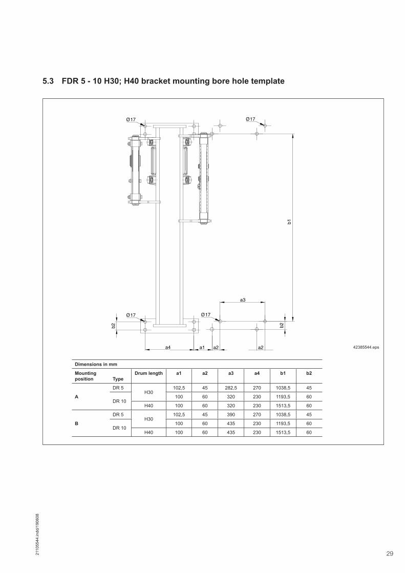
5.3 FDR 5 - 10 H30; H40 bracket mounting bore hole template
a4
b2
a2 a1 a2
b2
a3
b1
17
17 17
17
Dimensions in mm
Mounting position Type
Drum length a1 a2 a3 a4 b1 b2
A
DR 5 H30
102,5 45 282,5 270 1038,5 45
DR 10100 60 320 230 1193,5 60
H40 100 60 320 230 1513,5 60
B
DR 5H30
102,5 45 390 270 1038,5 45
DR 10100 60 435 230 1193,5 60
H40 100 60 435 230 1513,5 60
42385544.eps

30 2110
5544
.indd
/190
608
42387544.epsFig. 1
Mains connec-Control voltage, control signal
6.1 Electrical equipment Work on electrical equipment may only be carried out by qualified electricians or trained personnel, see also section 1 Safety instructions.Each Demag rope hoist is provided with a wiring diagram showing details of the controls.The wiring of the Demag rope hoist complies in all respects with current DIN VDE and accident prevention regulations. Unauthorized intervention and modifications may result in infringement of these regulations.The switchgear is designed for extreme conditions. However, its service life de-pends on usage.Advise operators to avoid inching (i.e. giving short pulses to the motor to obtain small movements) as far as possible, e.g. when attaching a load. It may cause excessive wear and premature failure of the switchgear.Corrosion on plastic (identifiable by dull, sooty or brittle surfaces) and metal com-ponents in enclosed switchgear housings can be caused by too frequent inching. Corroded parts must be replaced accordingly.
6.2 Mains connection and control signal
First check whether the voltage and frequency specified on the capacity plate match your mains supply.Voltage changing motors are wired in our works for the operating voltage stated in the order of the Demag rope hoist.The standard control voltage is 48 V 50/60 Hz. If the measured value exceeds or drops below the voltage specified on the devices by more than 10 %, the control transformer must be connected on the primary side according to the table in the circuit diagram (in the crane electrical equipment).The plug-in connection for the mains connection is the upper 4-pole connector (fig. 1), the lower plug-in connector is provided for supply of the 48 V control voltage and the CAN bus control signal.Plug in the relevant connectors and tighten the locking screws by hand.The required supply cable conductor cross sections and fuse links can be seen in section 2.4. Please note that the length of the supply line specified for a given cross section must not be exceeded in order to avoid excessive voltage drop.
6 Connection of the electrical equipment

312110
5544
.indd
/190
608
Since the rope hoist is fitted with a frequency inverter, the following additional con-nection requirements must be observed:• Connection to the public mains supply system without any further measures
must be checked in accordance with the provisions of standard EN 61000-3-2. The frequency inverters fulfil the emission limit value requirements of product
standard EN 61800-3. Increased requirements resulting from the application environment of the frequency inverter must be met by the use of optional com-ponents.
• Operation in a non-earthed system (IT system) is allowed after the Y capacitors inside the unit have been disconnected.
• Fault-free operation with a residual-current-operated circuit-breaker. is ensured with a tripping current ≥ 30 mA if the following items are considered:
- Residual-current-operated circuit-breakers sensitive to all types of currents (type B acc. to EN 50178), when connecting frequency inverters with two (L1/L2) or three-phase (L1/L2/L3) connection to the power supply
- The residual-current-operated circuit breaker protects a frequency inverter with a leakage-current reduced filter or without a radio interference suppres-sion filter.
- The Y capacitors inside the unit must be disconnected. This results in an increase of cable-bound interference transmission (EMC).
The required supply cable conductor cross sections and fuse links can be seen in section 2.4. Please note that the length of the supply line specified for a given cross section must not be exceeded in order to avoid excessive voltage drop.
Note:In order to obtain type of enclosure IP55, the following connectors must be used: • Insert of bush enclosure type VC-K-T2-R, art. no. 18 55 10 2, make Phoenix,
part no. 719 036 45 • Connector insert type VC-TFS4, art. no. 16 07 46 0, make Phoenix, part no.
710 012 45
The direction of the rope hoist‘s movement is dependent on the sequence of phases in the power supply. The load hook must move upwards when the control pendant switching element for „lifting“ is pressed. If this is not the case, two leads from the supply should be changed over to ensure proper functioning of the emer-gency limit switches.If the phases are changed over, the control system automatically switches the hoist motor motion off after briefly starting up. Error code 38 appears in the display of the DSE-10R control pendant.
Check the top and bottom hook positions and adjust properly.
Failure to do this may result in serious damage or injury.
6.3 Checking the direction of movement

32 2110
5544
.indd
/190
608
Crane and crab control using the CAN bus technology CANopen Safety• Redundant control system with 2 controllers monitoring each other• Transmission of all safety-relevant signals acc. to CANopen Safety• Permanent or cyclic monotoring of all safety functions• Safety concept uses crane contactor as second entity for switching off• On-board analysis and service system permits crane monitoring (optional)• Minimum cabling required, therefore reduced weight and space • Flexible adaptation due to modular PCB concept• Alternative control units can be plugged in• Functions which can be programmed as parameters:
- Load spectrum recorder to determine the remaining safe working period- MGS / ZMS overload protective devices (ZMS as an option)- Load summation for two crabs- Slack rope cut-off (optional)- Load display with selectable unit of measurement (t, kg, lbs, T)- SGDM/ BER function- Co-ordinated and safe operation of 2 crabs or 2 hoist units- Synchronous operation of 2 hoist units with frequency inverter- Reduction of load and speed in certain areas (optional)- Various by-pass / pass-through control types (optional)- Operating limit switch, rope limit switch, limit switch for phase-sequence error (optional)- Holding and catching brake (optional)
• Integrated monitoring devices- phase sequence- brake application- brake wear- speed- Overtemperature- control state of the contactors- limit switch sequence
6.4 Control system

332110
5544
.indd
/190
608
6.5 Control pendant
Demag DSE-10R multi-button pendant control switches are used to control the rope hoist as standard. Demag rope hoists are generally fitted with emergency limit switches and a (two-stage) test button in the DSE-10R control pendant. The test button can be used to by-pass the „lifting“ operating limit switch to check the emergency limit switch. The control pendant is fitted in accordance with the circuit diagram on the electrical equipment enclosure (see section 6.2).The control pendant should be suspended so that the bottom edge is approx. 1 m above floor level.The arrow symbols on the buttons must indicate the correct direction of the respec-tive movement.The control pendant is generally of plug-in design, this ensures service and main-tenance-friendly installation.
The DSE-10R consists of an integrated mechatronics solution, i.e. the actuating mechanical system acts on a magnet sensor system that evaluates the control commands via an electronic system.This makes stepless actuation of all three motion axes possible. For pole-changing drives, 2-stage buttons are used as an alternative.
The integrated DR control system features transmission of control signals from the DSE-10R control pendant to the DR/crane control system via a CAN bus. This makes it possible to reduce wiring requirements to a minimum. The number of con-nection diagrams is reduced to one diagram.The control cable is provided with a textile sheath as standard. A control cable with vulcanized strain relief cords (2TY cable) is available as an option.
The DSE-10R control pendant is provided with an integrated infra-red interface (IrDA) for reading and transmitting the service data of the DR rope hoist.
In addition, information on the load value and the service data (min. quantity) is available via the standard display. When the standard MGS load detector is used and the load is detected by means of slip calculation, the load value trend is displayed. When the strain gauge carrier link available as an option is used as load detector, the load is precisely displayed in the percent range.
The control pendant and the mains connection cable must be fitted by the custom-er in such a way that the connectors are not subjected to any tensile or transverse forces.The control cable of the control pendant is provided with vulcanised strain relief wire cords which must be fixed by the customer.
DSE-10R principle of operation
Wiring
IrDA infrared interface
Display
42360444.eps
Emergency stop
2-stage button:Horn/limit switch test
DSE-10R
6.5.1 DSE-10R control pendant
Connecting the control cable with vulcanised strain relief wire cords to the DR

34 2110
5544
.indd
/190
608
7 Rope reeving
Reeving methods
42583245.eps
2/1 4/1 4/2
7.1 Reeving methods
7.2 Reeving methods for the rope hoist
The Demag FDR rope hoist is supplied with the rope separate from the bottom block.Rope reeving arrangements 2/1, 4/1 and 4/2 on the Demag FDR rope hoist can be seen in the following figs. 3 – 5.Care must be taken to keep the rope tight and not to twist it while reeving.The rope is retained by means of a wedge and an anchorage which is incorporated into a special crossmember.The rope end is properly secured if the carrying fall is introduced along the verti-cal side of the anchorage, as in fig. 2, so that when under load the wedge remains visible above the anchorage and the dead end protrudes downwards by approx. 10 cm.
The rope may be replaced by Demag service engineers or an authorized specialist company.The method of securing the rope end by means of this anchorage is absolutely reliable and conforms to the relevant regulations. As an additional safety feature to prevent the dead end from slipping in accordance with ISO 4309. Fit the required rope clamp as shown in fig. 2. The rope must not be secured with a rope clamp fitted over both rope ends. This would cause bruising and uneven stress in the car-rying fall of the rope and thus lead to its destruction.
Check suspension of the rope socket.When fitting the rope socket, it must be ensured that the double spring clip is locked (see fig. 2).
Check fitting of the ZMS/MGS load detector.When fitting the retaining ring, make sure that the retaining ring engages the groove in the pin (see figs. 2 – 4). After fitting, it must be possible to turn the retain-ing ring easily.Grease the bearing points with a suitable adhesive lubricant. Part no. 472 933 44.

352110
5544
.indd
/190
608
42387044.eps
2/1 reeving
Fig. 2
RangeTightening torque
Rope clampDR 3
6 NmDR 5DR 10 33 Nm
Rope clamp
42382844.eps
Double spring clip

36 2110
5544
.indd
/190
608
4/1 reeving
42387244.eps
Fig. 3
RangeTightening torque
Rope clampDR 3
6 NmDR 5DR 10 33 Nm
Fitting the rope socket
Double spring clip
Rope clamp
Rope guiding in the bottom block
42387644.eps
Note:The rope is lead into or out of the protective cover through the bore holes (arrows).While fitting, push the plastic protec-tive covers completely down (see fig. on the left
42387844.eps
Fitting the overload protective device
Double spring clip

372110
5544
.indd
/190
608
Fig. 4
42386844.eps
4/2 rope reeving for DR 5 and DR 10
Rope anchorage with rope clamps(see section 10.7.2)
Rope anchorage with aluminium press fit(see section 10.7.2)
Fitting the bottom block for 4/2 reeving
Cable grip for assembly Part no.:dia. 8 mm – 15 mm 713 990 45
Thread cable grip into bottom block
Insert wire rope into the cable grip Push wire rope through bottom block with cable grip.Do not pull the cable grip.
Remove cable grip and repeat with the second wire rope on the other side of the bottom block.
42350444.eps 42350544.eps 42350644.eps
42350744.eps 42350844.eps 42350944.eps

38 2110
5544
.indd
/190
608
8 Putting into operation
8.1 Geared limit switch
8.1.1 Determining the switch-off points for the geared limit switch
The geared limit switch is fitted in the electrical equipment enclosure of the Demag rope hoist.It switches off the rope hoist when the top or bottom hook position is reached. The direction of movement can be reversed. The emergency limit switch must not be approached in normal operation.Operating limit switches are required where the end positions are approached regularly during normal operation.In such cases, the switches must be adjusted so that the operating limit switch is actuated first and then, i.e. if this fails to operate, the emergency limit switch.Accident prevention regulations require that the crane operator checks the emer-gency limit switch before starting work. This can be done by using the 2-stage button of the DSE-10R control pendant.The operating limit switch can be by-passed by pressing this button. In order to ap-proach the emergency limit switch, the hoist unit must be switched on and the test button pressed simultaneously. The 2-stage button must also be pressed in order to move the hook back out of the end position (lowering).Please refer to the relevant wiring diagram for the functions performed by the geared limit switch.
The emergency limit switches must be properly adjusted to ensure prevention of accidents and to avoid damage to the rope hoist. The emergency limit switches are adjusted before leaving the factory to avoid complete unwinding of the rope, only.Following installation of the rope hoist, they must be readjusted and checked for the particular operating conditions.If you wish to set the greatest possible lifting height for your specific operating conditions, it is essential to observe the following:The emergency limit switch for the top hook position must be set so that when it switches off the lifting movement, hook dimension C as specified in technical data sheet 203 675 44 is reached.The emergency limit switch for the bottom hook position must be set so that the load hook does not touch the floor.Setting the cut-out points is described in the setting instructions (section 8.2).
Table 1:
Range Retaining windings for reeving
2/1, 4/1 4/2
FDR 3 3 -
FDR 5 3 3,5
FDR 10 3 3,5
Ensure the correct number of retaining windings on the drum.

392110
5544
.indd
/190
608
Setting the contacts for individual adjustment:
Before setting the switching points, make sure that live contacts are provided with a guard to protect against accidental contact.
Allow for run-on.
Each contact is allocated to a cam disk which is infinitely adjustable. The cam disks can be adjusted independently by means of the “individual” adjust-ing screws.
When the “individual” adjusting screw is turned clockwise, the cam disk is also turned clockwise. The switching point is shifted upwards in accordance with the hook path.When the screw is turned anti-clockwise, the switching point is shifted downwards.Standard cam disks are designed in such a way that a max. useful path and a run-on path are available.
The geared limit switch is already permanently connected with the control system via the system connector cable. Move load hook of the rope hoist into the specified switch-off position (switch-off points see section 8.1.1 and 2.9). Turn the “individu-al” adjusting screw until the contact maker opens the contact to set the contacts.If the run-on path is exceeded, the contact either opens or closes.
The contacts are adjusted in blocks by means of the “block” adjusting screw. All cam disks are adjusted together, while the relative adjustment of the individual contacts remains unchanged. When the “block” adjusting screw is turned clock-wise, the cam disks are also turned clockwise.
Approach switch-off points several times to check the limit switch functions are operating correctly.
Setting the contacts for adjustment in blocks:
Operating principle
8.2 Setting geared limit switches Individual adjusting
screwBlock adjusting screw
42589444.eps
Adjustment
A 4 mm hexagon socket key is needed to adjust the geared limit switch.

40 2110
5544
.indd
/190
608
876
54
3 2 1 0 FE
DC
BA9876
54
3 2 1 0 FE
DC
BA9
876
54
3 2 1 0 FE
DC
BA9876
54
3 2 1 0 FE
DC
BA9
876
54
3 2 1 0 FE
DC
BA9876
54
3 2 1 0 FE
DC
BA9
887
65
43
21O
N
8.4 Inspection before putting the unit into operation
8.5 Safety instructions
8.6 Starting operation
8.3 125 % overload for the acceptance test
Overload test ONAfter DIP switch 6 has been switched from OFF to ON, the overload protective device is de-activated for 15 minutes and limited to 146% to carry out the crane acceptance test at 125 %. After 15 minutes or every time the hoist unit is switched off and on (start-up of the control system) or after switch 6 is reset to OFF, the overload protective device (110%) is active again.
The inspections specified in section 10.3, table 2 must be carried out when the hoist is put into operation for the first time. Check whether the mounting position and oil fill quantity match the order, see sections 2.7 and 2.8. The hoist gearbox vent valve included in the delivery must be fitted in the highest filling opening.
All fitting and assembly work must be completed in accordance with the operating instructions and the hoist rope must be greased. Operation with defective or damaged ropes results in a high risk of accident for persons and the rope hoist and is therefore prohibited. Any change or modification which prejudices safety must be reported to the near-est person responsible immediately. Repairs may only be carried out by experi-enced technicians.
See section 10.1
Note:All DIP switches are set to OFF by default.
Overload test ON
42662044.eps

412110
5544
.indd
/190
608
9 Taking the unit out of service at the end of the shift/for maintenance
Every rope hoist features an emergency-stop device with which all motions can be stopped in the event of a hazard.The emergency-stop button is arranged in the control pendant.To actuate the emergency-stop button, press the button until it reaches the end stop. It then locks automatically.To unlock the actuated emergency-stop button, turn the pushbutton in the direction of the arrow and release.The emergency-stop device must only be reset after the hazard and its cause have been eliminated.
When the work has been completed, position the bottom block outside the travel area. Switch off the power supply at the mains connection or isolating switch.
Maintenance work on Demag rope hoists must not commence before the load has been removed and the mains connection switch or isolating switch has been switched off.Verify safe isolation from the power supply.The relevant accident prevention regulations and statutory regulations must be observed for operation and maintenance.Required tests and inspections must be carried out. Comply with the following: - Section 1.9 Safety instructions for maintenance- Chapter 10, table 2 on page 43
42360444.eps
Emergency stop
2-stage button:Horn/limit switch test
DSE-10R
9.1 Emergency stop
9.2 Taking the unit out of service at the end of the shift
9.3 Taking the unit out of service for mainte-nance purposes

42 2110
5544
.indd
/190
608
The crane operator must carry out inspections in accordance with table 2 before starting work. Rope hoists must be taken out of service immediately if any defects relating to operating safety and reliability are detected.Such defects are e.g.: • brake or emergency limit switch failure,• damage to the rope,• unusual noise in the gearbox, etc.
The specified inspection and maintenance intervals (table 2) apply to normal rope hoist service conditions.If routine maintenance reveals that the intervals are too long or too short, they should be adapted to the specific operating conditions.For repairs, only use genuine Demag parts (see spare parts list).The use of spare parts not approved by Demag renders any liability and guarantee claims void.
When 90% of the theoretical duration of service has passed – if the hoist is cor-rectly classified after 8 to 10 years – the owner must arrange for a general over-haul GO to be carried out. A general overhaul must be carried out on reaching the end of the theoretical duration of service, at the latest.During the general overhaul the following parts must be replaced in addition to the checks and work specified in the inspection and maintenance schedule (see table 2).• Gear wheels of the gearbox• Gearbox bearings• Motor• Rope drum• Gear oil• Connecting elements• Switchgear in the control systemThe small parts (screws, washers ...) to be replaced during maintenance and as-sembly work are not listed separately. The general overhaul carried out by the manufacturer or a specialist company authorized by the manufacturer fulfils the condition for continued operation of the rope hoist.Thus the relevant accident prevention regulations and the BGV D8 are complied with.Further utilization is approved when an expert engineer has entered the conditions for further utilization into the test and inspection booklet. Completion of the general overhaul must be confirmed in the test and inspection booklet and a further period of utilization in accordance with FEM 9.755 must be entered.
The general overhaul may be carried out by expert engineers of Demag or an authorized specialist company.
10.1 Inspection before starting work and during operation
10.2 Inspection and mainte-nance schedule
10 Inspections/maintenance/general overhaul GO
10.3 General overhaul GO

432110
5544
.indd
/190
608
Table 2Inspection and maintenance schedule
The specified maintenance intervals apply to normal rope hoist service conditions.If the annual calculation of the actual duration of service S indicates that the theo-retical duration of service D will be reached before a period of 8 – 10 years, regular maintenance work must be adapted to the operating conditions and maintenance must be carried out at shorter intervals.For repairs, only use genuine Demag parts (see spare parts list).
Inspection before putting the unit into operation for the first time, before starting work and during operation
See sec-tion
Before first putting
into opera-tion
before starting
work
Every 6 months
Once per year
Check rope securing devices and rope guide X X
Check electrical switchgear and wiring 6.1 X X
Check operation of limit switch 8.1 X X X
Check strain relieving elements, control cable and control pendant housing for damage X X X
Check operation of the brake X X X
Check operation of overload protective device X X
Check lubrication of rope X X
Check hook and hook safety catch X X X
Check during time of operation Check adhesive lubricant in bearing points of return sheaves, crossheads, compensating sheaves and pins of rope anchorage, re-grease as required X
Check suspension of the rope anchorage, check play of the setbolt/pin in counter bore hole for the retaining plate. Check double spring clip for correct fit. 7.2 X
Check brake displacement, adjust as required X
Check all connections (bolts, welds etc.) X
Check rope securing devices and play of rope guide on drum X
Check rope for damage and broken wires X X
Lubricate rope X X
Check load hooks for cracks, deformation and wear X
Check hook safety catch for deformation X
Check bottom block X
Check securing elements (clips, bolts, etc.) for tight fit and corrosion X
Check and apply or supplement corrosion protection, as required 6.1/3.4 X
Change oil of main hoist gearbox Every 8 – 10 years
Check plastic components of limit switch for corrosion X
Check electrical enclosure seals X
Check power supply line X
General overhaul
The general overhaul should coincide with the annual inspection On reaching the theoretical duration of service
Fit rope hoist-specific Demag GO set X
The small parts (screws, washers ...) to be replaced during maintenance and assembly work are not listed separately. During the general overhaul, the checks and work specified in the inspection and maintenance schedule must be carried out.

44 2110
5544
.indd
/190
608
The following information on the assessment and maintenance of wire ropes has been compiled on the basis of German, European and international standards as well as on the relevant trade literature and is to be regarded only as the most sig-nificant information which is not intended to be complete, but to help the owner of Demag rope hoists make himself familiar with the topic of „Discarding wire ropes“. Furthermore, all national standards, regulations or any legislation of other coun-tries must be complied with and considered together with the above information or they take priority, as applicable.The assessment of the replacement state of wear of wire ropes requires many years of experience and expert knowledge. An assessment may only be carried out by a Demag service engineer or by a corresponding specialist.A visual check must always be carried out over the entire length of the rope, in-cluding points which cannot normally be seen, critical points must be inspected with particular care and attention. In order to discover broken strands more easily, the load must be removed from the unit and the rope bent manually along its entire working length. Run the rope through your hand protected by a thick glove. The bending radius should be ap-proximately that of the rope sheaves.A wire rope must be discarded when its condition is no longer considered to be safe for further operation. Wire ropes must be discarded when the number of visible broken load-carrying wires in the external strands at the worst spot has reached the following figures (see table 3), counted over a reference length of rope of 6 times or 30 times the rope diameter, whichever gives the worst result.Critical points are, e.g.:1. Rope zones subject to the highest number of alternating bending cycles and in
particular to alternative deflection. This also applies to rope zones on compen-sating sheaves which are subject to a very high number of reversed bending cycles due to rope swing or uneven winding of rope drums. These rope sections show increased abrasion and a higher number of broken wires.
2. The zones at which loads are picked up, i.e. rope zones which are on a rope sheave during a preferred load pick-up point or are wound up onto or off a rope drum.
3. Rope anchorages loading the wire rope in addition to normal tensile load. Vibra-tions in the transition area and moisture penetrating into the rope anchorage result in corrosion and broken wires.
4. Rope zones on rope drums. The load pick-up point on the rope drum is subject to increased wear (abrasion, broken wires and/or structural changes).
5. Rope zones exposed to aggressive media, general weather conditions or high temperatures. Observe the specifications of the manufacturer of the wire rope and the lubricant used.
The rope may be replaced by Demag service engineers or an authorized specialist company.
10.4 Discarding the wire rope
Table 3Wire ropes must be replaced to ISO 4309, table 1, when the following numbers of broken wires are visible
1) Rope construction: 8 x 19 with IWCR steel rope core, LH = left hand ordinary lay rope, bright surface, with pressure sleeve on one end.2) Rope construction: 8 x 21 with IWCR steel rope core, LH = left hand ordinary lay rope, bright surface, with pressure sleeve on one end.3) Rope construction: 10 x 26 with IWCR steel rope core, LH = left hand ordinary lay rope, bright surface, with pressure sleeve on one end.
Group of mecha-nisms to FEM/ISO
1Am/M4 2m/M5, 3m/M6, 4m/M7 1Am/M4 2m/M5, 3m/M6, 4m/M7
Rope dia.Number of broken wires over a
rope length of6 x rope diameter
Number of broken wires over a rope length of
6 x rope diameter
Number of broken wires over a rope length of
30 x rope diameter
Number of broken wires over a rope length of
30 x rope diameter
mmNumber of
broken wiresRope length
mmNumber of
broken wiresRope length
mmNumber of
broken wiresRope length
mmNumber of
broken wiresRope length
mm7
1) 642
1342
13210
26210
9 54 54 270 27013 78 78 390 3907
2) 742
1442
14210
29210
9 54 54 270 27013 3) 10 78 21 78 21 390 42 390

452110
5544
.indd
/190
608
10.5 Wire ropes10.5.1 Construction, application and
reeving of wire ropes
Range DR 10
Reeving arrangement 2/1 4/1 4/2
Hook path m 12 20 6 10 5,8 11,4 5,8 11,4
Rope construction 1) 3) 1) 3) 1) 3) 1) 3) 1) 2)
Group of mechanisms
1Am/M4 X X X X X
2m/M5 X X X X X
3m/M6 X X X X X
4m/M7 X X X X X
Wire rope dia. mm 13 13 13 13 9 9
Theor. breaking force approx. kN 164,93 197,9 164,93 197,9 164,93 197,9 164,93 197,9 76,67 91,70
Minimum breaking force kN 132 166,2 132 166,2 132 166,2 132 166,2 63 79,30
Rope grade N/mm² 1960 2160 1960 2160 1960 2160 1960 216 1960 2160
Rope length m 28,25 44,25 29,3 45,25 31,6 53,8 31,6 53,8
Range DR 3
Reeving arrangement 2/1 4/1
Hook path m 12 20 12 20 6 10 6 10
Rope construction 1) 2) 1) 2)
Group of mechanisms
2m/M5 X X
3m/M6 X X
4m/M7 X X
Wire rope dia. mm 7 7 7 7
Theor. breaking force approx. kN 49,08 49,60 49,08 49,60
Minimum breaking force kN 39,7 42,6 39,7 42,6
Rope grade N/mm² 1960 1960 1960 1960
Rope length m 26,95 43 26,95 43 27,7 43,7 27,7 43,7
1) Rope construction: 8 x 19 with IWCR steel rope core, LH = left hand ordinary lay rope, bright surface, with pressure sleeve on one end.2) Rope construction: 8 x 21 or 8 x 25 with IWCR steel rope core, LH = left hand ordinary lay rope, bright surface, with pressure sleeve on one end.3) Rope construction: 10 x 26 with IWCR steel rope core, LH = left hand ordinary lay rope, bright surface, with pressure sleeve on one end.
Range DR 5
Reeving arrangement 2/1 4/1 4/2
Hook path m 12 20 6 10 9,9
Rope construction 1) 2) 1) 2) 1) 2) 1) 2) 1)
Group of mechanisms
1Am/M4 X X X X X
2m/M5 X X X X X
3m/M6 X X X X X
4m/M7 X X X X X
Wire rope dia. mm 9 9 9 9 7
Theor. breaking force approx. kN 76,67 91,70 76,67 91,70 76,67 91,70 76,67 91,70 45,8
Minimum breaking force kN 63 79,30 63 79,30 63 79,30 63 79,30 39,8
Rope grade N/mm² 1960 2160 1960 2160 1960 2160 1960 2160 1960
Rope length m 27,3 43,45 28,1 44,3 46,8

46 2110
5544
.indd
/190
608
43228744.eps
10.6 Wear limits on rope sheaves
The cross section of the rope groove must not be less than the specified minimum dimension tmin at any position. Negative impressions in the rope groove must not exceed the specified maximum dimension.
Size Reeving Groove root dia.
Rope dia.
Min. fl ange plate thickness
tmin
Max. depth of wire impressions
DR32/1, 4/1
160 7 4,9 0,4
DR5182 9 5,6 0,5
4/2 160 7 4,9 0,4
DR102/1, 4/1
23013
5,60,7
2806,3
4/2 3,5

472110
5544
.indd
/190
608
10.7 Fitting the wire rope and rope guide
Before a rope is reeved, the whole length of the rope should be rolled out on the ground. Any twisting of the rope should be strictly avoided.
The following hazards must be considered when replacing the wire rope:• Crushing hazard• Shearing hazard• Hazards arising through gripping or winding• Hazards arising through drawing-in or entanglement
CorrectIncorrect
41116144.eps
10.7.1 Fitting the rope
42385844.eps
Fitting the rope anchorageFit rope anchorage (1) in the counter bore hole of the rope drum.
1

48 2110
5544
.indd
/190
608
Insert and bolt the torque bracket and side sections I and II in the bore holes of the segments.
Note:When fitting the rope guide, the screws must always be tightened with a torque wrench (6 Nm), while countering with the locknuts.
Suspend the rope end with aluminium press fit (3) in rope anchorage (1) on the drum.
4238594444.eps
Then slide clip (2) directly behind the rope anchorage and fix it.
42584844.eps
Fitting the rope guide
Fit rear side section (1) on segment 2 (2).Loosely connect segments 1 and 2 with the upper screw/nut.
42386144.eps
42387444.eps
The rope guide must be disassembled before it is fitted to the drum.(1) Segment 1 with rope
guide rollers(2) Torque bracket(3) Side section I(4) Side section II(5) Segment 2 Segment 2 is identi-
fied by a bore hole (arrow) on the cir-cumference
(6) Socket head screw Tightening torque
6 Nm(7) Nut (8) Plate
12
3 4
5
6
7
7
6
8
1
2
3
1

492110
5544
.indd
/190
608
42386744.eps
Lift thrust roller (8) off the rope against the spring force by means of a screwdriver (arrow) and remove split pin (9).
42386444.eps
Place side section 1 (5) into the bore holes on the segment, slide the screws through from the rear and apply the nuts, then tighten the screws to a torque of 6 Nm.
Align the rope guide so that can you can slide torque bracket (6) into the guide.Place the torque bracket onto the guide rod and slide it into the guide of the segment.
Insert screws from the rear, fit plate (7) and nuts. Tighten screws to 6 Nm.Note: The short screw is on the outside.
42386544.eps
42386644.eps
Guide the two segments (1+2) over the rope drum from above. Fit segment with rope guide rollers (3) so that the rollers are above the wire rope on the drum.Slide the rope guide sideways until it rests in the empty groove next to the rope on the drum
42386244.eps
Insert the lower screw of the segments (4) and tighten to a torque of 6 Nm. Check the position of the rope guide in the groove of the drum, then tighten the upper fastening screw also to a torque of 6 Nm.
42386344.eps
1
2
3
4
5
6
7 9
8

50 2110
5544
.indd
/190
608
10.7.2 Fitting the rope on double-groove models
Suspend the rope end with the aluminium end sleeve (arrow) in the rope anchor-age on the drum. Fit the clip. Do not wind the rope on the drum.Fit the rope, see section 10.6.1.Completely unroll the wire rope and thread the rope end through the rope sheave of the bottom block by using a cable grip as in fig. 5, then through the compensat-ing sheave and the second sheave of the bottom block. Remove the cable grip from the end of the rope and secure it at the other end of the drum using the rope clamps.Wind the rope tightly approx. 4 turns round the drum on both sides. To do this, switch on the hoist motor for lifting and run the rope through your hand protected by a thick glove.Care must be taken to keep the rope tight and not to twist it while reeving. Then fit the rope guides on both sides – see section 10.6.1.
4/2 reeving
Rope anchorage with rope clampsRope anchorage with aluminium end sleeve
42386944.eps42385944.eps
10.7.4 Lubricating the wire rope
10.7.3 Shortening the wire rope The rope must neither be shortened on or separated from the aluminium end sleeve nor the twisted rope end. If in exceptional cases, it is necessary to shorten the wire rope, it must be done in compliance with engineering standards.
Grease the rope with a suitable lubricant and preservative, e.g. Cedracon. En-sure that the agent reaches the interior of the rope structure, part no. 665 013 44.Grease the bearing points of the top block, crosshead, compensating sheave, the pin of the rope anchorage and the guide rod of the rope guide with a suitable adhe-sive lubricant, part no. 472 933 44.
Tightening torque 40 Nm

512110
5544
.indd
/190
608
10.8 Regular inspections and monitoring meas-ures for load hooks
If a check or inspection reveals that these components are worn beyond the di-mensions shown in fig. 6 and the table, or if deformations and cracks can be seen in these parts, the affected parts must be replaced at once by genuine spare parts.
Fig. 6 42063744.eps
Check the hook safety catch for correct functioning and for any damage.
1) Permissible variation: +10%2) Permissible variation: -5%
Range DR 3 DR 5 DR 10
Reeving 2/1 4/1 2/1, 4/2 4/1 2/1, 4/2 4/1Group of mechanisms
2m/M5...4m/M7 1Am/M4...4m/M7 2m/M5...4m/M7
1Am/M4...3m/M6 4m/M7
Hook size 1 1,6 1,6 2,5 2,5 4 5a2 nominal dimension 1) 40 45 45 50 50 56 63
a2 max. dimension 44 49,5 49,5 55 55 61,6 69,3
h2 nominal dimension 2) 40 48 48 58 58 67 75
h2 min. dimension 38 45,6 45,6 55,1 55,1 63,6 71,2

52 2110
5544
.indd
/190
608
11 Calculating the actual duration of service
When using powered hoist units, the owner must determine and record the used share of the theoretical duration of service for the hoist, see BGV D8.The load spectrum is recorded and calculated by means of the control system integrated in the DR. The still available duration of service is shown in the display of the control pendant for the DR Pro.Read the value and enter it into the test and inspection booklet when the annual inspection is carried out.The value displayed is indicated in %.A general overhaul must be arranged to be carried when 90 % of the service life has elapsed (10 % shown in the display).
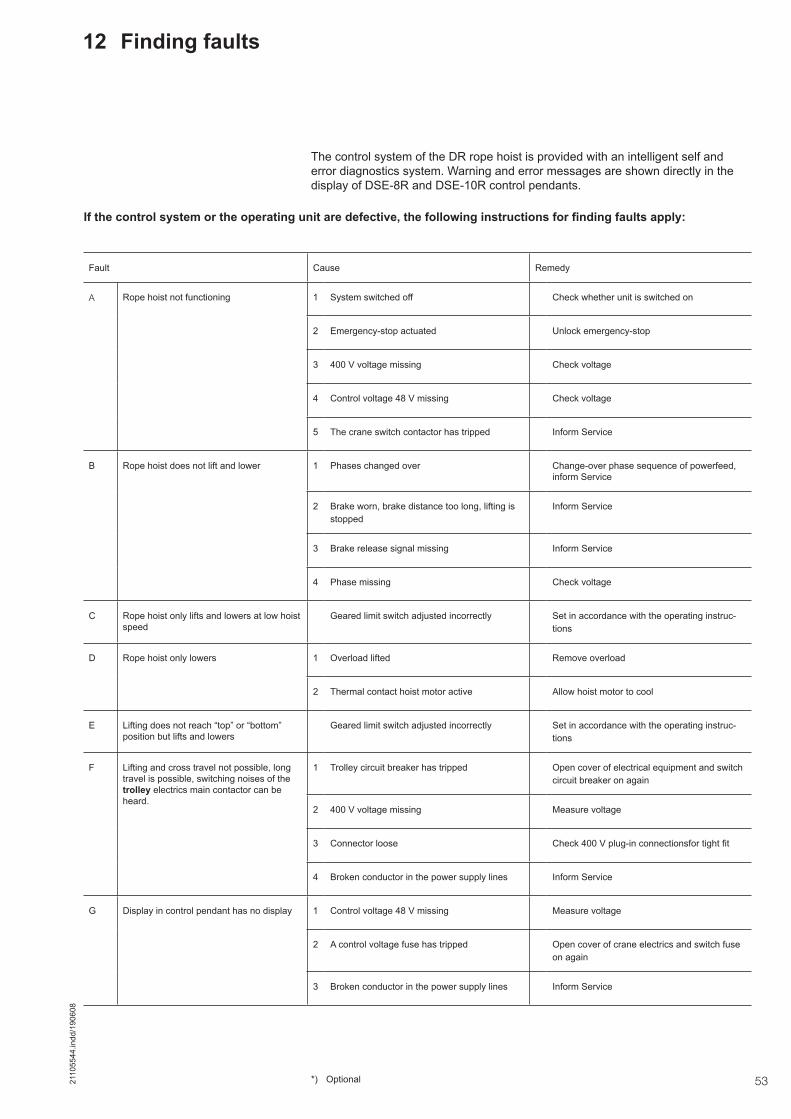
532110
5544
.indd
/190
608
12 Finding faults
If the control system or the operating unit are defective, the following instructions for finding faults apply:
Fault Cause Remedy
A Rope hoist not functioning 1 System switched off Check whether unit is switched on
2 Emergency-stop actuated Unlock emergency-stop
3 400 V voltage missing Check voltage
4 Control voltage 48 V missing Check voltage
5 The crane switch contactor has tripped Inform Service
B Rope hoist does not lift and lower 1 Phases changed over Change-over phase sequence of powerfeed, inform Service
2 Brake worn, brake distance too long, lifting is stopped
Inform Service
3 Brake release signal missing Inform Service
4 Phase missing Check voltage
C Rope hoist only lifts and lowers at low hoist speed
Geared limit switch adjusted incorrectly Set in accordance with the operating instruc-tions
D Rope hoist only lowers 1 Overload lifted Remove overload
2 Thermal contact hoist motor active Allow hoist motor to cool
E Lifting does not reach “top” or “bottom” position but lifts and lowers
Geared limit switch adjusted incorrectly Set in accordance with the operating instruc-tions
F Lifting and cross travel not possible, long travel is possible, switching noises of the trolley electrics main contactor can be heard.
1 Trolley circuit breaker has tripped Open cover of electrical equipment and switch circuit breaker on again
2 400 V voltage missing Measure voltage
3 Connector loose Check 400 V plug-in connectionsfor tight fit
4 Broken conductor in the power supply lines Inform Service
G Display in control pendant has no display 1 Control voltage 48 V missing Measure voltage
2 A control voltage fuse has tripped Open cover of crane electrics and switch fuse on again
3 Broken conductor in the power supply lines Inform Service
*) Optional
The control system of the DR rope hoist is provided with an intelligent self and error diagnostics system. Warning and error messages are shown directly in the display of DSE-8R and DSE-10R control pendants.

54 2110
5544
.indd
/190
608
Notes

552110
5544
.indd
/190
608
Notes

Demag Cranes & Components GmbHP.O. Box 67, D-58286 WetterTelephone +49 (0) 2335 92-0 · Telefax +49 (0) 2335 927676www.demagcranes.com
Prin
ted
in G
erm
any
Reproduction in whole or in part only with prior consent of Demag Cranes & Components GmbH, D-58286 Wetter Subject to change. Not liable for errors or omissions.
The current addresses of the sales offices in Germany and the subsidiaries and agencies worldwide can be found on the Demag Cranes & Components homepage at www.demagcranes.com ► Contact and Demag worldwide