Operating Instructions Data Transmission System … Instructions Data Transmission System ... design...
42
Operating Instructions Data Transmission System POWERTRANS ® Ib BAL0512-0001-E www.conductix.com Original Page 1 of 42
-
Upload
truongliem -
Category
Documents
-
view
215 -
download
1
Transcript of Operating Instructions Data Transmission System … Instructions Data Transmission System ... design...

Operating Instructions Data Transmission System POWERTRANS
® Ib
BAL0512-0001-E
www.conductix.com Original Page 1 of 42

Operating Instructions Data Transmission System POWERTRANS
® Ib
BAL0512-0001-E
www.conductix.com Original Page 2 of 42
Contents Page
1 General notes .......................................................................................................................................................................... 4
1.1 Information about these assembly and operating instructions ................................................................................. 4
1.2 Limitation of liability .................................................................................................................................................. 4
1.3 Copyright .................................................................................................................................................................. 5
1.4 Spare parts ............................................................................................................................................................... 5
1.5 Warranty and guarantee ........................................................................................................................................... 5
1.6 Customer service ...................................................................................................................................................... 5
2 For your Safety ........................................................................................................................................................................ 6
2.1 Personal security ...................................................................................................................................................... 6
2.2 Equipment security ................................................................................................................................................... 6
2.3 Personnel requirements ........................................................................................................................................... 7
2.4 Intended use ............................................................................................................................................................. 7
2.5 Reference to additional documents .......................................................................................................................... 7
3 Delivery .................................................................................................................................................................................... 8
3.1 Volume of delivery .................................................................................................................................................... 8
3.2 Transport damage .................................................................................................................................................... 9
4 Technical data .......................................................................................................................................................................... 9
4.1 General data ............................................................................................................................................................. 9
4.2 Dimensions ............................................................................................................................................................. 10
4.3 Standard connection diagram ................................................................................................................................. 11
5 Function description ............................................................................................................................................................... 12

Operating Instructions Data Transmission System POWERTRANS
® Ib
BAL0512-0001-E
www.conductix.com Original Page 3 of 42
6 Assembling ............................................................................................................................................................................ 13
6.1 Fixation of the main unit and interface module ....................................................................................................... 13
6.2 Electric connection ................................................................................................................................................. 13
6.3 Shielding ................................................................................................................................................................. 14
6.4 Recommended configuration of the conductor rail ................................................................................................. 14
6.5 Bus terminators ...................................................................................................................................................... 15
7 Prior Tests .............................................................................................................................................................................. 15
7.1 Check all connections ............................................................................................................................................. 15
7.2 Measurement of termination resistors .................................................................................................................... 15
7.3 Check the data rate ................................................................................................................................................ 16
7.4 Check the bus termination resistors ....................................................................................................................... 17
8 Operation ............................................................................................................................................................................... 18
8.1 Operation signal ..................................................................................................................................................... 18
8.2 State of LEDs ......................................................................................................................................................... 18
8.3 Operational test ...................................................................................................................................................... 20
8.4 Measurement of the output signal .......................................................................................................................... 21
8.5 Increasing the Profibus parameter “Retry Limit” ..................................................................................................... 22
9 Fault diagnostics .................................................................................................................................................................... 23
10 Special features ..................................................................................................................................................................... 24
10.1 Voltage change 230 V to 115 V .............................................................................................................................. 24
10.2 Special requirements for DH+ Interface Module..................................................................................................... 26
10.3 Compatibility between POWERTRANS® Ia and POWERTRANS® Ib .................................................................... 27
11 FAQ - Frequently Asked Questions ....................................................................................................................................... 29
12 List of figures .......................................................................................................................................................................... 41
Operating Instructions Data Transmission System POWERTRANS
® Ib
BAL0512-0001-E
www.conductix.com Original Page 4 of 42
1 General notes
1.1 Information about these assembly and operating instructions
These assembly and operating instructions make it possible for you to work with the device safely and efficiently.
The BAL0512-0001-E assembly and operating instructions are a part of the device, and must be kept accessible to personnel at all
times in its immediate vicinity. Personnel must read these assembly and operating instructions carefully and understand them
before starting any work. The basic prerequisite for workplace safety is the observance of all safety notes and handling instructions
in these assembly and operating instructions.
Local accident protection regulations and general safety guidelines for the area of use of the device also apply.
The figures in these assembly and operating instructions are to be used for basic understanding, and may deviate from the actual
design of the device.
1.2 Limitation of liability
All data and information in these assembly and operating instructions has been compiled while taking the valid standards and
regulations as well as the state-of-the art and our long years of experience and knowledge into consideration.
The manufacturer is in no way liable for damages resulting from:
Failure to follow the assembly and operating instructions
Improper use
Use by untrained personnel
Unauthorized modifications
Technical changes
Use of unauthorized spare parts and accessories
The actual scope of delivery may differ from the explanations and illustrations described here for special variants, if additional
order options are utilized, or due to the latest technical changes.
The obligations agreed upon in the delivery agreement and our General Terms of Business apply, as do the delivery conditions of
the manufacturer and all regulations applicable at the time the contract was concluded.
All products are subject to technical modifications in the context of improvement of function and further development.

Operating Instructions Data Transmission System POWERTRANS
® Ib
BAL0512-0001-E
www.conductix.com Original Page 5 of 42
1.3 Copyright
These assembly and operating instructions are subject to copyright, and are exclusively intended for internal use.
Disclosure of the assembly and operating instructions to third parties, copying them in any way - even in part - as well as reuse
and/or disclosure of their content are not permitted except for internal use, without the written approval of the manufacturer.
Violations will be subject to damages. This will not exclude additional claims.
1.4 Spare parts
WARNING!
Safety risk due to wrong spare parts!
Wrong or faulty spare parts can result in damages, malfunctions or complete failure as well as impair
safety.
Use only original spare parts of the manufacturer!
Order spare parts from your contracted dealer or directly from the manufacturer. The necessary contact data can be found on the
last page of these operating instructions.
1.5 Warranty and guarantee
The terms of warranty and guarantee can be found in the General Terms of Business of the manufacturer.
1.6 Customer service
Our customer service is available for technical questions. The necessary contact data can be found on the last page of these
instructions.
Our employees are also always interested in new information and experience from the field that can be valuable for the
improvement of our products.

Operating Instructions Data Transmission System POWERTRANS
® Ib
BAL0512-0001-E
www.conductix.com Original Page 6 of 42
2 For your Safety
2.1 Personal security
Switch off all units/machines/systems that are affected by the assembly
Disconnect these units/machines/systems from the power supply if required.
Control the correct operation of the safety systems (e.g. emergency stop buttons)
Install warning signs if required, to avoid starting the operation unintentionally.
A system must only be programmed and configured while it is not in operation!
When starting the operation a voltage of ±70 V on the data cables has to be ensured!
After having completed the mounting/repair works carry out a test run of the systems and check the correct operation of the
safety systems!
Only release systems that work without any fault!
NOTE!
Mechanic and Electricity
We assume that you are familiar with the appropriate knowledge of mechanics and electricity!
2.2 Equipment security
The data transmission system fulfills the quality requirements of ISO 9001.
POWERTRANS® Ib units and accessories leave our company - with regard to safety technology - in a perfect condition.
Do not open the main unit and the interface module!
Opening the case affects the operational security and voids the warranty!
On POWERTRANS® Ib units the interface entry - and the conductor bar entry - are short-circuit proof.
Place the data and current supply cables in such a way that none of the cables will be caught during operation and that no
cable will be squashed, bent or damaged in any way.

Operating Instructions Data Transmission System POWERTRANS
® Ib
BAL0512-0001-E
www.conductix.com Original Page 7 of 42
2.3 Personnel requirements
WARNING!
Injury due to insufficient qualifications!
Improper use can result in serious injury to person and property. Therefore:
All activities may only be performed by qualified personnel.
All installation and commissioning works as well as repair work and disassembly have to be carried out by qualified staff
(DIN 60364 respectively CENELEC HD 384 or DIN VDE 0100 and DIN 60664 or DIN VDE 0110 and national safety rules).
Qualified staffs according to the safety regulations are persons that are familiar with the installation, assembly, commissioning and
operation of the energy supply system and that have the appropriate qualifications.
The Conductix-Wampfler AG is not responsible for damages or breakdowns that have been caused by not observing the operating
instructions.
2.4 Intended use
The equipment is exclusively designed and built for the intended use described here.
The POWERTRANS® Ib is used for transmission of field bus data over:
conductor rail
slip ring body
wire
WARNING!
Possible injury resulting from improper use!
Any application that deviates from or goes beyond the intended use of the machine can result in a
hazardous situation. Therefore:
The device may only be used as intended.
All specifications in these assembly and operating instructions must strictly be followed.
Non-intended use particularly includes the following:
Using the device with unapproved accessories not authorized by the manufacturer.
Claims of any kind due to damages from improper use are excluded. The operator bears sole liability for all damages resulting
from unintended use.
2.5 Reference to additional documents
For further information refer to the:
Catalogue KAT0512-0001 POWERTRANS® Ib

Operating Instructions Data Transmission System POWERTRANS
® Ib
BAL0512-0001-E
www.conductix.com Original Page 8 of 42
3 Delivery
3.1 Volume of delivery
Please verify immediately if the material has been delivered completely. The relevant document is the advice note.
1 main unit with socket (3 poles) for the power supply and socket (5 poles) for the conductor bar connection. 2 pc support
bracket with fasteners are enclosed loose.
1 interface module
1 pair of optical fibers pre-manufactured
One functional unit POWERTRANS® Ib includes the following standard elements:
Fig. 1 POWERTRANS® standard elements
Item Description
1 Main unit
2 Pair of optical fibers
3 Interface module
4 Serial number, e.g. „B54“ or „HV-2463“
5 Power supply, Socket (3 poles); net
6 Socket (5 poles) conductor bar
7 Earth conductor connection (PE), M5 with ground strap
5
3
6
1
2 4
7

Operating Instructions Data Transmission System POWERTRANS
® Ib
BAL0512-0001-E
www.conductix.com Original Page 9 of 42
3.2 Transport damage
Transport damage can only be claimed if the supplying company is advised immediately.
Please enclose the following documents to your return shipment:
Company, contact and address
Order and serial number
Description of the failure
4 Technical data
4.1 General data
Technical data
Supply voltage: 230 V ± 10%
115 V ± 10%
Frequency: 50 / 60 Hz
Fuse: 0,8 A at 230 V
1,6 A at 115 V
Protection class: IP 20
Output voltage: ± 70 V
Output current: max. 1 A
Ambient operating temperature: 0 -50°C
Tightening torque of plug: 4,42 in.lb / 0,50 Nm
Suitable for field wiring, wire size: AWG 14 / 2,5 mm2
Mode: halfduplex (fullduplex see catalogue)
NOTE!
Instruction
Never open the unit!

Operating Instructions Data Transmission System POWERTRANS
® Ib
BAL0512-0001-E
www.conductix.com Original Page 10 of 42
4.2 Dimensions
Fig. 2 Dimensions of POWERTRANS® Ib
Main unit
Interface module

Operating Instructions Data Transmission System POWERTRANS
® Ib
BAL0512-0001-E
www.conductix.com Original Page 11 of 42
4.3 Standard connection diagram There is a standard connection diagram shown: Application example for half duplex (2 poles).
Fig. 3 Standard connection diagram
Sie
men
s P
LC
Sie
men
s bu
s
conn
ecto
r
RxD
/TxD
-P 3
RxD
/TxD
-N 8
3 r
ed
8 g
reen
data
cab
le
shie
ld
Sie
men
s bu
s
conn
ecto
r
Inte
rfac
e m
odul
e R
S 4
85
5 S
GN
D
3 R
/T-P
8 R
/T-N
fib
er o
ut
fiber
in
fiber
out
fib
er in
fiber
opt
ical
Soc
ket
3 po
les
pow
er
Con
nect
or
5 po
les
Con
duct
or b
ar
red
red
24 V
DC
N
PE
L
min
. 0,7
5 m
m2
max
. 2.5
mm
2
scre
ened
pow
er
Mai
n un
it
Co
nd
uct
ix-W
amp
fler
PO
WE
RT
RA
NS
®
Bus
load
resi
stor
Co
nd
uct
ix-W
amp
fler
Co
nd
uct
or
bar
PO
WE
RT
RA
NS
® lb
Sta
tion
1
SP
S/P
LC
SP
S/P
LC
PO
WE
RT
RA
NS
® lb
Sta
tion
2
SP
S/P
LC
Pai
r of
opt
ical
fibe
rs
Inte
rfac
e m
odul
e
PO
WE
RT
RA
NS
® lb
Sta
tion
3
Mai
n un
it
Ter
min
ator
/
cond
ucto
r ba
r
Ter
min
ator
/
cond
ucto
r ba
r
max
. 2,5
mm
2

Operating Instructions Data Transmission System POWERTRANS
® Ib
BAL0512-0001-E
www.conductix.com Original Page 12 of 42
5 Function description
Principle
POWERTRANS® increases the signal level of ±5 V to ±70 V (potential free) and reduces it at the output to the particular interface
level. It works at the physical level, has no affect on the bus protocol and changes no telegrams.
Data rates
Depending on the configuration, data rates from 9,6 Kbit/s to 1,5 MBit/s are possible (No modification of the device required).
For data transmission over conductor bar we advise a data rate of 187,5 Kbit/s, but depending on several attributes of the
installation, data rates up to 500 Kbit/s are possible. For sliprings data rates up to 1,5 MBit/s are possible.
In general: The lower the data rate, the lower is the error rate! For the most installations a data rate of 187,5 Kbit/s is sufficient.
The bus cycle time should be the half of the program cycle time. The bus cycle time can be calculated or measured with a bus
tester or protocol analyzer.
Transmission
POWERTRANS® only works at the physical layer. The bus telegram will not be changed, POWERTRANS® is not an active bus
user.
From the module’s perspective, POWERTRANS® is comparable to a Repeater or a Hub.
At the conductor bar (high voltage) POWERTRANS® works with its own physical layer.
RS485
All RS485 based bus systems can be transmitted, e.g. Profibus DP, Profibus-FMS, DH485
DH+
The transmission of DH+ protocol is approved by Allen-Bradley’s licence. In spite of the same physical layer (technically possible) the
transmission of DH+ in association with the RIO-protocol of Allen-Bradley is not allowed.
RS232
RS232 connections can be transmitted by use of an interface converter (available from the Conductix-Wampfler AG).
NOTE!
FAQs
For more details of function and use please refer to the FAQ chapter on page 29.
Bus terminators of the bus cable have to be installed according to the
manufacturer’s instructions for the installed control. There is no bus
resistor on the interface. The application of converters
(e.g. RS232 on RS485) requires bus terminators at the interfaces.
Operating Instructions Data Transmission System POWERTRANS
® Ib
BAL0512-0001-E
www.conductix.com Original Page 13 of 42
6 Assembling
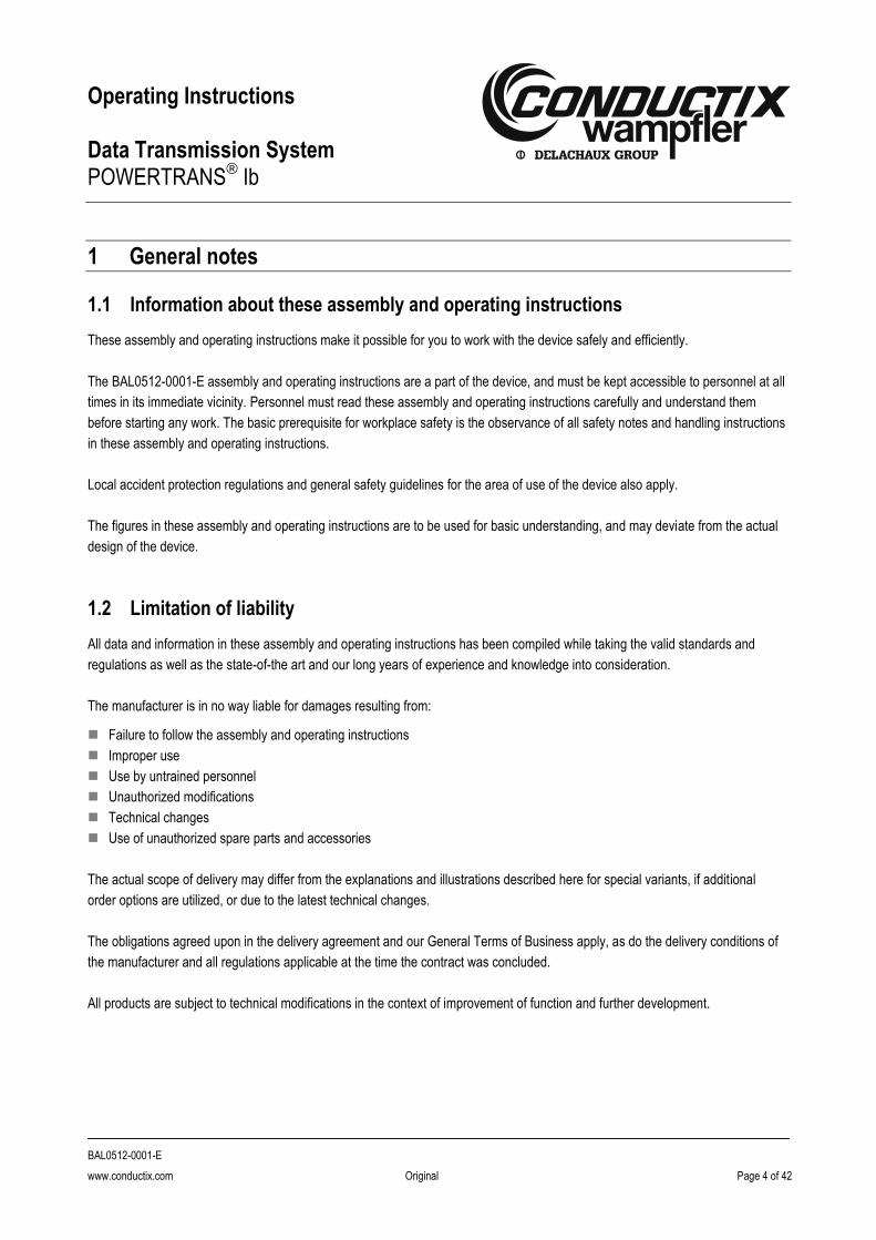
6.1 Fixation of the main unit and interface module
The support brackets of the main unit can be fixed at the front or long side.
Main unit and interface module should be arranged in such a way that any interference from other components (e.g. frequency
inverters or relay boards) will be prevented. We recommend a minimum distance of 100 mm.
Fig. 4 Fixation of main unit and interface module
Item Description
1 Long-side fixation possibility for the support brackets
2 The interface module must be fixed on a mounting bar TS 35 (cap bar)
6.2 Electric connection (Also see standard connection diagram, page 11)
For the electric connection the following steps has to be considered:
For operation without interference we recommend equipping the supply system with a line filter and a differential current control unit.
To assure continuity, even when the power supply plug is disconnected, the main unit is equipped with an additional PE connector
(M5). Connect the main units with the ground strap to the subplate of the cabinet.
2 1

Operating Instructions Data Transmission System POWERTRANS
® Ib
BAL0512-0001-E
www.conductix.com Original Page 14 of 42
The POWERTRANS® Ib unit presents a bus unit. The Sub-D, respectively DH+ connection on the interface module component, is
connected by a shielded cable according to the specifications given by the PLC manufacturer. In principle each bus segment has to
be terminated on both ends. On Profibus applications for example, the bus terminators in the sockets have to be activated
accordingly. On DH+ bus systems, the bus terminators have to be activated from “outside” as well.
The supply voltage of the interface modules has to be grounded one-sided. Connect the wire as marked on the label.
Rating of internal fuse: 250 V 1,6 A or 0,8 A.
WARNING!
Electric shock!
DISCONNECT AND LOCKOUT ALL POWER SOURCES BEFORE SERVICING OR EQUIVALENT!
6.3 Shielding
Shielding is a method to reduce (damp) electromagnetic environmental influences.
Interference currents on cable shield are led off to ground over the shield bus that has a conductive connection to the ground
conductor. In order to avoid that those interference currents might become a source of disturbance themselves, it is very important
to provide a low-impedance connection to the protective conductor.
In general the shield of the cables should only be connected on one side. Only a one-sided connection of the shield will allow good
interference suppression in high frequencies.
The shield of the data cable is connected according to the specifications of the corresponding PLC manufacturer (often at the
socket case).
6.4 Recommended configuration of the conductor rail
Fig. 5 Configuration of the conductor rail (recommended)
Enclosed conductor rail 0842 Single-pole conductor rail

Operating Instructions Data Transmission System POWERTRANS
® Ib
BAL0512-0001-E
www.conductix.com Original Page 15 of 42
6.5 Bus terminators
Arrangement conductor rail Terminator [Ω] Arrangement of the bus terminators at the outlet of the
stationary POWERTRANS® unit or at the beginning of
the conductor rail and at the end of the conductor rail.
It must be observed that the connecting points of the
connection cables of terminators and connections are
really at the end of the conductor rail.
Conductor rail straight, slip ring, annular 150
Conductor rail 2 alleys 150
Conductor rail 3 alleys 330 / 330
Conductor rail 4 alleys 470 / 470
7 Prior Tests
NOTE!
Tests
Before switching on the power supply the following tests described below has to be done.
7.1 Check all connections
The Plug-in unit is delivered in a wooden transport frame. Up to four Plug-in units can be transported in a single frame:
Check all plugs and connections, if all wires are connected correctly according to this document.
Check the fibre optic cables for the correct connection.
Check the conductor bar and the collector shoes for correct connection and contact pressure
7.2 Measurement of termination resistors
NOTE!
Power supply
The power supply of all POWERTRANS® Ib units has to be switched off!
The following measures has to be taken (a and b correspond to the figure below):
Measure the resistance of the installation (high voltage side) with a multimeter (a)
Measure the resistance at the mobile unit (here the transition resistance of the conductor bar is in addition) (b) Reference values: 50 … 100 Ohms.

Operating Instructions Data Transmission System POWERTRANS
® Ib
BAL0512-0001-E
www.conductix.com Original Page 16 of 42
Fig. 6 Measuring of the resistance
After finishing the measurements reconnect all plugs.
7.3 Check the data rate
Check the correct data rate at the PLC (customer). Check in the lower table, if the data rate is allowable for the total length of the
installation. If not, a lower data rate has to be chosen.
Total length of the installation in meters relating to the data rate:
Data rate in kbps
Length of straight arrangement
System with 2 paths System with 3 paths Annular system
500 300 200 inadvisable 160
187,5 800 400 300 410
93,75 1600 800 600 800
19,2 1600 1600 1000 1000
9,6 1600 1600 1000 1000
NOTE!
Installation length
The total length is limited by voltage drop and/or signal propagation delay and not by reflections or distortions.
The stated lengths refer to one system with one master and one slave. With several slaves a reduction is necessary!
Conductor bar
150 150 Powertrans® Ib main unit
50…100
Powertrans® Ib
main unit
50…100
(a)
(b)

Operating Instructions Data Transmission System POWERTRANS
® Ib
BAL0512-0001-E
www.conductix.com Original Page 17 of 42
7.4 Check the bus termination resistors
For RS485 every bus segment must have an active bus termination at the beginning and end (see drawing). The supply voltage for
the termination resistor is given by the interface module. It is recommended to use special bus connectors with switchable
termination resistors.
Fig. 7 Bus system with termination resistors
PLC Master
Inter- face
module
fiber optic cable
PT main unit
termination
resistor
PT-
main unit
fiber optic
cable
Inter- face
module
PLC unit
(Slave)
conductor bar
PLC unit (Slave)
PLC unit
(Slave)
PLC unit (Slave)
PLC unit (Slave)
Bus- termination
Bus- termination
Bus- termination
Bus- termination
bus
cabl
e
bus
cabl
e

Operating Instructions Data Transmission System POWERTRANS
® Ib
BAL0512-0001-E
www.conductix.com Original Page 18 of 42
8 Operation
8.1 Operation signal
Signaling by the four LEDs (POWER, DATA TO PLC, DATA FROM PLC and DIRECTION) shows, that there is a correct data
exchange between the individual POWERTRANS® Ib units. Depending on the data transmission rate the LEDs will flash or shine
permanently.
8.2 State of LEDs
For exact identifying the LED colors within this manual even in black/white/grayscale circumstances consider the overview below.
In order to ensure the understandability under all conditions the grayscale symbols with the first character of the color name are
used within this manual.
Original LED color name
Original LED color symbol
Equivalent LED symbol in grayscale Description
Green Power ON (power OK, device ready)
Yellow Data to PLC (data flow from POWERTRANS® to PLC)
Orange Data from PLC (data flow from PLC to POWERTRANS®)
Red Direction
(red LED „on“: data direction from POWERTRANS® to conductor bar red LED „off“: data direction from conductor bar to POWERTRANS®
Red Monitor (LED has no function)
Fig. 8 State of LEDs

Operating Instructions Data Transmission System POWERTRANS
® Ib
BAL0512-0001-E
www.conductix.com Original Page 19 of 42
Fig. 9 LEDs of system, numbers and characters corresponding to the table below.
NOTE!
LED flickering
Depending on the data rate the Data-LEDs may flicker or light constantly.
Interface module
Master-side
PT-Main unit Master-side
PT-Main unit Slave-side
Interface module
Slave-side Cause
correct operation
* * bus cable master side interrupted or
fibre optic „IN“ Main unit Master interrupted or
fibre optic Main unit Master reverse-poled
* fibre optic „OUT” Main unit Master interrupted
* * feed cable of conductor bar or conductor bar
interrupted
* * fibre optic „OUT“ Main unit Slave interrupted or
fibre optic Main unit Slave reverse-poled
* feed cable cond.bar or cond. bar reverse-poled
or fibre optic „IN“ Main unit Slave interrupted or
Bus cable Slave side interrupted
* Depending on data traffic the yellow and/or the orange LED at the interface module could illuminate.
After restarting the Interface module (power supply OFF/ON) only the green LED illuminates.
PLC (Master)
Interface module
fibre optic
PT Main unit
Bus-cable
termination
resistor
PT Main unit
fibre optic
Interface-module
PLC (Slave)
Conductor bar
4
1
3
2
A B
C
C D
E
Bus-cable

Operating Instructions Data Transmission System POWERTRANS
® Ib
BAL0512-0001-E
www.conductix.com Original Page 20 of 42
8.3 Operational test After switching on the supply voltage, the operation of the POWERTRANS® system can be tested.
Fig. 10 Potential layout of a POWERTRANS® Ib system
If the PLC is communicating, the LEDs at the POWERTRANS® Ib main unit as well as at the interface module should light as showed at Fig. 8 at page 18. If not, follow the instructions as described.
R
Con
duct
or b
ar
PLC mobile
Interface unit
Powertrans® Ib main unit
PLC stationary
Powertrans® Ib main unit
Interface unit
R

Operating Instructions Data Transmission System POWERTRANS
® Ib
BAL0512-0001-E
www.conductix.com Original Page 21 of 42
8.4 Measurement of the output signal
The output signal has to be tested under load (correct connection of the termination resistors). The measurement has to be done
differential (channel A - channel B) with a two channel oscilloscope with math function, e.g. Fluke Scopemeter.
Fig. 11 Measuring of the output signal
The peak-peak voltage has to be in-between 125 to 145 V.
The edges have to be steep, the level has to be horizontal, the intersection between edge and level has to be square and without
spikes.
According to the data traffic and the data rate the bit width and the idle periods varied.
Fig. 12 Output level
CH B CH A
Powertrans® Ib main unit Conductor bar
150 150
>125V
CH A
CH B
CH A –
CH B
Not correct (wrong termination resistor) Correct
Operating Instructions Data Transmission System POWERTRANS
® Ib
BAL0512-0001-E
www.conductix.com Original Page 22 of 42
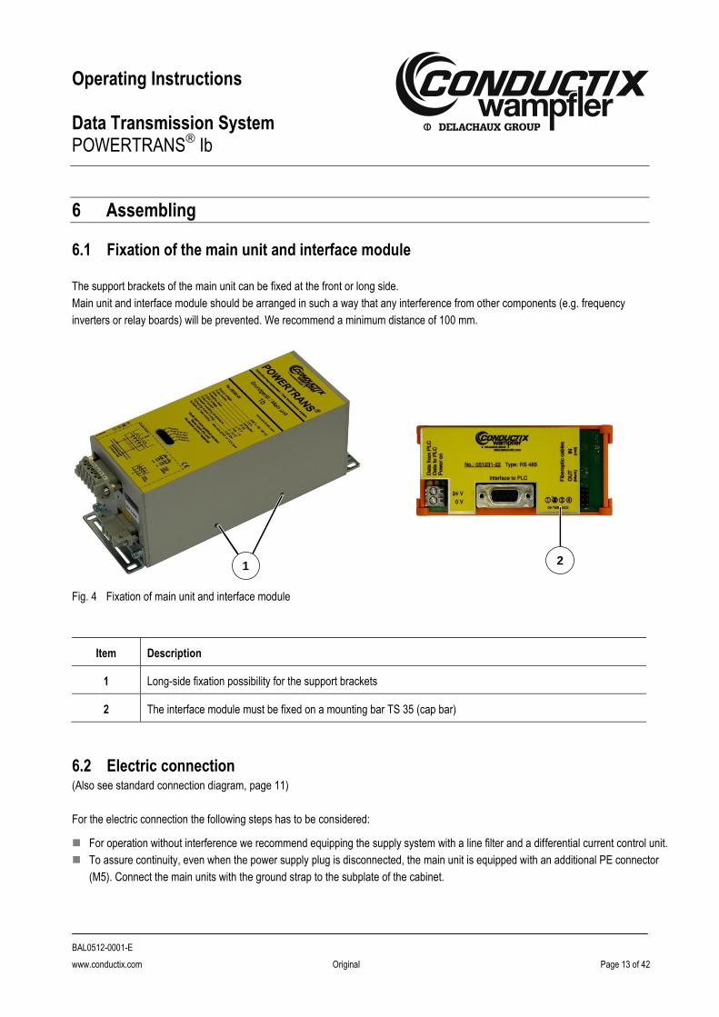
8.5 Increasing the Profibus parameter “Retry Limit”
The parameter “Retry Limit” defines the maximum number of retries of the master after receiving bad telegrams of the slave.
The standard value of Profibus DP is “1”. On data transmission over conductor bars or slip rings it is possible to get short
interruptions. Therefore this value has to be increased.
Fig. 13 Retry Limit, step 1
Fig. 14 Retry Limit, step 2
Choose baud rate
Choose “user defined”
“Bus parameters”
Increase value “Retry limit”
Operating Instructions Data Transmission System POWERTRANS
® Ib
BAL0512-0001-E
www.conductix.com Original Page 23 of 42
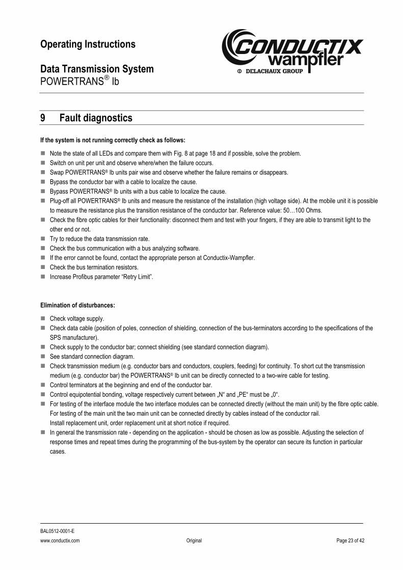
9 Fault diagnostics
If the system is not running correctly check as follows:
Note the state of all LEDs and compare them with Fig. 8 at page 18 and if possible, solve the problem.
Switch on unit per unit and observe where/when the failure occurs.
Swap POWERTRANS® Ib units pair wise and observe whether the failure remains or disappears.
Bypass the conductor bar with a cable to localize the cause.
Bypass POWERTRANS® Ib units with a bus cable to localize the cause.
Plug-off all POWERTRANS® Ib units and measure the resistance of the installation (high voltage side). At the mobile unit it is possible
to measure the resistance plus the transition resistance of the conductor bar. Reference value: 50…100 Ohms.
Check the fibre optic cables for their functionality: disconnect them and test with your fingers, if they are able to transmit light to the
other end or not.
Try to reduce the data transmission rate.
Check the bus communication with a bus analyzing software.
If the error cannot be found, contact the appropriate person at Conductix-Wampfler.
Check the bus termination resistors.
Increase Profibus parameter “Retry Limit”.
Elimination of disturbances:
Check voltage supply.
Check data cable (position of poles, connection of shielding, connection of the bus-terminators according to the specifications of the
SPS manufacturer).
Check supply to the conductor bar; connect shielding (see standard connection diagram).
See standard connection diagram.
Check transmission medium (e.g. conductor bars and conductors, couplers, feeding) for continuity. To short cut the transmission
medium (e.g. conductor bar) the POWERTRANS® Ib unit can be directly connected to a two-wire cable for testing.
Control terminators at the beginning and end of the conductor bar.
Control equipotential bonding, voltage respectively current between „N“ and „PE“ must be „0“.
For testing of the interface module the two interface modules can be connected directly (without the main unit) by the fibre optic cable.
For testing of the main unit the two main unit can be connected directly by cables instead of the conductor rail.
Install replacement unit, order replacement unit at short notice if required.
In general the transmission rate - depending on the application - should be chosen as low as possible. Adjusting the selection of
response times and repeat times during the programming of the bus-system by the operator can secure its function in particular
cases.

Operating Instructions Data Transmission System POWERTRANS
® Ib
BAL0512-0001-E
www.conductix.com Original Page 24 of 42
10 Special features
10.1 Voltage change 230 V to 115 V
NOTE!
Qualified personnel!
The voltage change may only be carried out by qualified personnel and after consultation Conductix-Wampfler.
After the change Conductix-Wampfler has to be informed and the POWERTRANS® serial number has to be forwarded.
Order number:
230 V version: 051221-30
115 V version: 051221-31
See the steps to change the voltage selection from 230V to 115V of POWERTRANS® Ib as follows.
Step Measures 230 V version 115 V version
1 Open device
2 Change arrangement of wiring See drawing, position 1 See drawing, position 1
3 Change fuses (2 pcs.) 800 mA T
Wickmann 19195 / 1,6 A T
4 Close device
1
2

Operating Instructions Data Transmission System POWERTRANS
® Ib
BAL0512-0001-E
www.conductix.com Original Page 25 of 42
Step Measures 230 V version 115 V version
5 Change description at label at front plate with waterproof pen
230 V
115 V
6 Change descriptions at label with waterproof pen
230 V / 0,8 A
115 V / 1,6 A
115V 230V

Operating Instructions Data Transmission System POWERTRANS
® Ib
BAL0512-0001-E
www.conductix.com Original Page 26 of 42
10.2 Special requirements for DH+ Interface Module
Order number: 051231-20
Recommendations for using the DH+ interface module:
1. Use at least 2 collectors on each data rail. In case of extreme or dirty environment 3 collectors are recommended. At least
space for a third collector should be considered.
2. Use silver graphite collector shoes.
3. Use data metal conductor rails (stainless steel).
4. Do not use in extended temperature (beyond 0 to +50°C) or corrosive atmosphere environments.
5. Perform maintenance of collector arms, shoes and conductor rails according to the maintenance instruction of the used
conductor rail type, at least every 3 month (dirty contacts and rails, contact wear, contact bounce).
6. Refer to A-B publication “Industrial Automation Wiring and Grounding Guidelines for Noise Immunity”, (Publication 1770-4.1).
7. Recommendations relating to DH+ cabling and products:
• Limit baud rate to 57.6 K or 115.2 K
• Limit DH+ cable length: 1000 ft at 115.2 K and 2000 ft at 57.6 K
• Limit number of DH+ nodes to 16
• Use 82 Ω terminators and daisy chain routing
DH+ Compatibility
Some older DH+ products are not compatible with 82 Ω including the following list:
1771-KA, KA2, KF, KX1
1773-KAA, KAB
1774-KA
1775-KA, GA, RM, S4A, S4B, SR
1784-KS
1785-KA3, -KE (Series A or B), -540
8200 products.
8. Error detection should be implemented by the application:
The application program or ladder logic should continually monitor communication errors and retry status (error counts and
retry counts) that is provided in A-B products. Errors and retries should not normally occur. If they do, maintenance should be
performed as soon as possible.
9. A device should be programmed or configured only when the device is not moving on the rails.
10. No claims are made that this equipment is appropriate for any level of safety risks. Safety protection should be provided by
the application design using appropriate independent means.
Brands and Trademarks
“A-B”: Allen-Bradley brand of products from Rockwell Automation, a business of Rockwell International Corporation.
“DH+”, “Data Highway Plus”, Allen-Bradley” and “PLC” are trademarks of Rockwell Automation, a business of Rockwell
International Corporation.

Operating Instructions Data Transmission System POWERTRANS
® Ib
BAL0512-0001-E
www.conductix.com Original Page 27 of 42
10.3 Compatibility between POWERTRANS® Ia and POWERTRANS® Ib
For replacement of POWERTRANS® Ia by POWERTRANS® Ib please refer to the following instructions:
Electrical wiring, POWERTRANS® Ia
Fig. 15 Electrical wiring, POWERTRANS® Ia
Electrical wiring, POWERTRANS® Ib
Fig. 16 Electrical wiring, POWERTRANS® Ib
POWERTRANS® Ib will replace POWERTRANS® Ia. POWERTRANS® Ib is electrically compatible but needs an additional 24 V
AC/DC supply voltage for the Interface Module.
Siemens PLC Siemens bus connector
RxD/TxD-P 3
RxD/TxD-N 8
3 red
8 green
data cable
shield
Siemens bus connector
Interface module RS 485
5 SGND
3 R/T-P
8 R/T-N
fiber out
fiber in fiber out
fiber in
fiber optical
Socket 3 poles
power
Connector 5 poles Conductor bar
red
red
24 V DC
Siemens S5 115 U
Siemens bus connector
RxD/TxD-P 3
RxD/TxD-N 8
3 green
8 yellow
Data cable
Shield
Bus - terminator
Shield
Housing
in
in
out
out
Net PE

Operating Instructions Data Transmission System POWERTRANS
® Ib
BAL0512-0001-E
www.conductix.com Original Page 28 of 42
Replacement
In case of the replacement of POWERTRANS® Ia by POWERTRANS® Ib please refer to the following procedure:
1. Switch off the power supply of all POWERTRANS® Ia units.
2. Disconnect the plug at the defective POWERTRANS® Ia unit, dismount the unit.
3. Check the size for the location for POWERTRANS® Ib main unit und interface module.
4. Install POWERTRANS® Ib main unit and interface module and connect the fibre optic cables (see standard connection
diagram).
5. Install the 24 V power supply for the interface module and connect it to the module (see standard connection diagram).
6. Cut the plugs of the cables (power supply and conductor rail) of the POWERTRANS® Ia unit and connect them to the plugs
of the POWERTRANS® Ib main unit (see standard connection diagram). Connect the plugs to the main unit.
NOTE!
Data rate
Adjustment of the data rate at the POWERTRANS® Ib is not necessary.
7. Connect the plug of the bus cable to the interface module. If the interface module is the last bus device switch on the bus
terminator in the plug.
NOTE!
Bus terminator
The bus terminator for the bus cable is integrated in the POWERTRANS® Ia-unit. In the interface module of POWERTRANS® Ib the bus terminator is not integrated, therefore bus cables with integrated bus terminator in the plugs have to be used.
8. Check the correct connection of all cables (respect to false polarity!).
9. Switch on power supply 24 V and 115/230 V.
10. Function control by LED´s (see signals/LED).
WARNING!
Injury due to insufficient qualifications!
The carry out of the replacement is only allowed by qualified and skilled electrical personnel!
Operating Instructions Data Transmission System POWERTRANS
® Ib
BAL0512-0001-E
www.conductix.com Original Page 29 of 42
11 FAQ - Frequently Asked Questions
Questions overview: Page
Where is POWERTRANS® used? ................................................................................................................................................... 30
Why is POWERTRANS® used? ...................................................................................................................................................... 30
How does POWERTRANS® operate? ............................................................................................................................................. 30
Which data rates are possible? ....................................................................................................................................................... 30
Which bus cable should be used for the connection of POWERTRANS®?..................................................................................... 30
What are reflections? ...................................................................................................................................................................... 31
Is POWERTRANS® adapted for multi-master-systems? ................................................................................................................. 31
What is possible with POWERTRANS® to transmit ......................................................................................................................... 31
What is not possible with POWERTRANS® to transmit................................................................................................................... 31
What is to be considered for the MPI protocol? .............................................................................................................................. 32
How many field bus units can be connected to one POWERTRANS® unit? ................................................................................... 32
Is POWERTRANS® certified for Profibus? ...................................................................................................................................... 32
Must POWERTRANS® be considered within the bus design? ........................................................................................................ 32
Which installation topologies can be realized? ................................................................................................................................ 32
Which material should be used for conductor bar and collector shoes? ......................................................................................... 34
How long does POWERTRANS® need for initialization? ................................................................................................................ 34
How long may the feed cable to the conductor bar or to the collector shoe be? ............................................................................. 35
How to increase the reliability of the system? ................................................................................................................................. 35
What could be the cause if the bus system does not start? ............................................................................................................ 35
Is a parameterization of POWERTRANS® I necessary? ................................................................................................................. 36
Things to consider at start-up of the bus system ............................................................................................................................. 36
What to consider when using interface converters, links or gateways? .......................................................................................... 36
At what temperatures can the devices operate? ............................................................................................................................. 36
What does a “POWERTRANS® segment” mean?........................................................................................................................... 36
How many POWERTRANS® units can operate on one segment? .................................................................................................. 36
How to realize a crossing from one segment to the next? .............................................................................................................. 37
What is to be considered in the change-over from POWERTRANS® Ia to POWERTRANS® Ib?.................................................... 38
Are POWERTRANS® Ia und POWERTRANS® Ib units compatible?............................................................................................... 38
What must be considered when extending an old installation? ....................................................................................................... 38
Where do the termination resistors (at the high-voltage side) have to be connected? ................................................................... 39
Which cable (between POWERTRANS® I and conductor bar) has to be used? ............................................................................. 39
The installation was running a long time without problemss, but now there are more and more problems? .................................. 39
Can security relevant data (e.g. e-stop) be transmitted with POWERTRANS® I? ........................................................................... 39
What to do if the system stops working? ......................................................................................................................................... 40
How to measure the waveform on the high-voltage side? .............................................................................................................. 40
How do the waveforms on the high-voltage side look like for different termination resistors? ........................................................ 40

Operating Instructions Data Transmission System POWERTRANS
® Ib
BAL0512-0001-E
www.conductix.com Original Page 30 of 42
Where is POWERTRANS® used?
It’s used for transmission of field bus data over
conductor rail
slip ring body
wire
Why is POWERTRANS® used?
Very high signal to noise ratio
By increasing of the signal level of ±5 V to ±70 V there is a high noise immunity
No shielding necessary
Due to the high signal to noise ratio is no shielding necessary.
Minimization of contact problems
Due to the high signal voltage and current the contaminations at the contact area will be disposed and so the signal transfer under
tough conditions is warranted.
How does POWERTRANS® operate?
POWERTRANS® increases the signal level of ±5 V to ±70 V (potential free) and reduces it at the output to the particular interface
level.
POWERTRANS® works at the physical level, has no affect on the bus protocol and changes no telegrams.
Which data rates are possible?
Depending on the configuration, data rates from 9,6 kBit/s to 1,5 MBit/s are possible.
(No modification of the device required, see item 21, page 10)
For data transmission over conductor bar we advise a data rate of 187,5 kBit/s, but depending on several attributes of the installation,
data rates up to 500 kBit/s are possible.
For sliprings data rates up to 1,5 MBit/s are possible.
In general: the lower the data rate, the lower is the error rate! For the most installations a data rate of 187,5kBit/s is sufficient.
The bus cycle time should be the half of the program cycle time. The bus cycle time can be calculated or measured with a bus tester
or protocol analyzer.
Which bus cable should be used for the connection of POWERTRANS®?
To connect the bus system the same cable as the remaining bus cable should be used to avoid reflections.

Operating Instructions Data Transmission System POWERTRANS
® Ib
BAL0512-0001-E
www.conductix.com Original Page 31 of 42
What are reflections?
A reflection causes the same signal twice at the receiver with a little time delay. Reflections result from changes of the impedance of
the wire, esp. at an intersection of different wires or at the end of a not terminated wire (changeover of impedance ZW~150 Ohm to
infinite).
To avoid reflections at the end of a wire, the use of termination resistors is needed.
Is POWERTRANS® adapted for multi-master-systems?
POWERTRANS® can be used for pure Master-Slave-Systems as well as for multi-master-systems.
What is possible with POWERTRANS® to transmit
POWERTRANS® only works at the physical layer. The bus telegram will not be changed; POWERTRANS® is not an active bus
user.
From the interface module’s perspective, POWERTRANS® is comparable to a Repeater or a Hub.
At the conductor bar (high voltage) POWERTRANS® works with its own physical layer.
RS485
All RS485 based bus systems can be transmitted, e.g. Profibus DP, Profibus-FMS, DH485
DH+
The transmission of DH+ protocol is approved by Allen-Bradley’s license. In spite of the same physical layer (technically possible) the
transmission of DH+ in association with the RIO-protocol of Allen-Bradley is not allowed.
RS232
RS232 connections can be transmitted by use of an interface converter (available from Conductix-Wampfler).
What is not possible with POWERTRANS® to transmit
RS422 e.g. Interbus-S (DIN 19258)
RS422 (full duplex)-transmission is possible with the main unit, but there is no interface module available yet. For full duplex
connections there are 4 conductor bars or wires necessary.
Profibus-PA (IEC-1158-2)
Profibus-PA is based on IEC-1158-2 transfer system and cannot be transmitted. But it’s possible to realize the transmission with
Profibus-DP (RS485) by using segment couplers or links. POWERTRANS® must be installed outside the explosive atmosphere.
ASI (EN 50295)
The transmission can be realized with Profibus-DP (RS485) by using gateways.
CAN (ISO11898 und ISO 11519), DeviceNet, ControlNet
Transmission of CAN bus is not possible.
Ethernet (IEEE8802.3)
There are gateways Ethernet RS485. Ethernet has data rates of 10 MBit/s, 100 MBit/s or 1 GBit/s, POWERTRANS® I is able to
transmit data with maximal 1,5 MBit/s, this has to be considered in the planning.

Operating Instructions Data Transmission System POWERTRANS
® Ib
BAL0512-0001-E
www.conductix.com Original Page 32 of 42
What is to be considered for the MPI protocol?
For the transmission of MPI data signals, the system operates with only one segment. Changeover of segments or crossing of
section points can’t be realized due to technical limitations. Also see item 25 „segments“.
How many field bus units can be connected to one POWERTRANS® unit?
Every POWERTRANS® interface module generates a new field bus segment. How many field bus units can be connected to one
segment, has to be found out from the field bus standard.
In one Profibus segment, for example, it is possible to connect 32 units. If there are more units to be connected, it is necessary to
use repeaters to create new segments.
Is POWERTRANS® certified for Profibus?
It is only possible to certificate active Profibus units. POWERTRANS® is no active unit, so it can’t be certified. The interface module
is electrically the same as Profibus units (RS485 standard), but with no change to the protocol.
Must POWERTRANS® be considered within the bus design?
At the electrical design POWERTRANS® has to be considered. POWERTRANS® cuts the bus in several segments; every segment
has to be terminated at the electrical beginning and end. The termination at the bus side is done in general with bus connectors which
have switchable termination resistors. At the high voltage side it is necessary to use termination resistors as specified in the catalog.
No changes are needed to the parameters, but it is recommended to increase the “retry” parameter. We suggest allowing 7 retries
before the bus stops. For Profibus this parameter is labeled „Retry-limit“.
Which installation topologies can be realized?
Straight lines
Beginning and end of the straight line have to be terminated.
Z Z
D1
D2
PT PT
PT
PLC
PLC
PLC

Operating Instructions Data Transmission System POWERTRANS
® Ib
BAL0512-0001-E
www.conductix.com Original Page 33 of 42
Straight lines with centre feed
Beginning and end of the straight line have to be terminated.
Many lanes
Every end of lane has to be terminated.
Z Z
Z Z
Z Z
Z Z Z Z
PT
PT
PT
PLC
PLC
PLC
PLC
PT
Z Z
D1
D2
PT PT
PLC PLC
PT
PLC

Operating Instructions Data Transmission System POWERTRANS
® Ib
BAL0512-0001-E
www.conductix.com Original Page 34 of 42
Circular lines
Circular, resp. closed lines, should be avoided, because multipath propagation leads to fading and therefore to interruptions. Multipath
propagation is mainly critical in large installations. If possible, section points have to be inserted to make the line electrically “straight”.
Which material should be used for conductor bar and collector shoes?
For common applications copper busbars are used with copper-graphite collector-shoes.
In aggressive ambient conditions (for example chemicals industry) the use of datametal busbar is recommendable.
In dusty conditions (for example brickyard or concrete plant) a regular maintenance and cleaning is necessary.
How long does POWERTRANS® need for initialization?
After switch-on the power, POWERTRANS® is ready within 5 ms.
PLC
PLC
PT
PT
PLC
PLC
PT
PT
“Closed” ring Circular line with section point
Operating Instructions Data Transmission System POWERTRANS
® Ib
BAL0512-0001-E
www.conductix.com Original Page 35 of 42
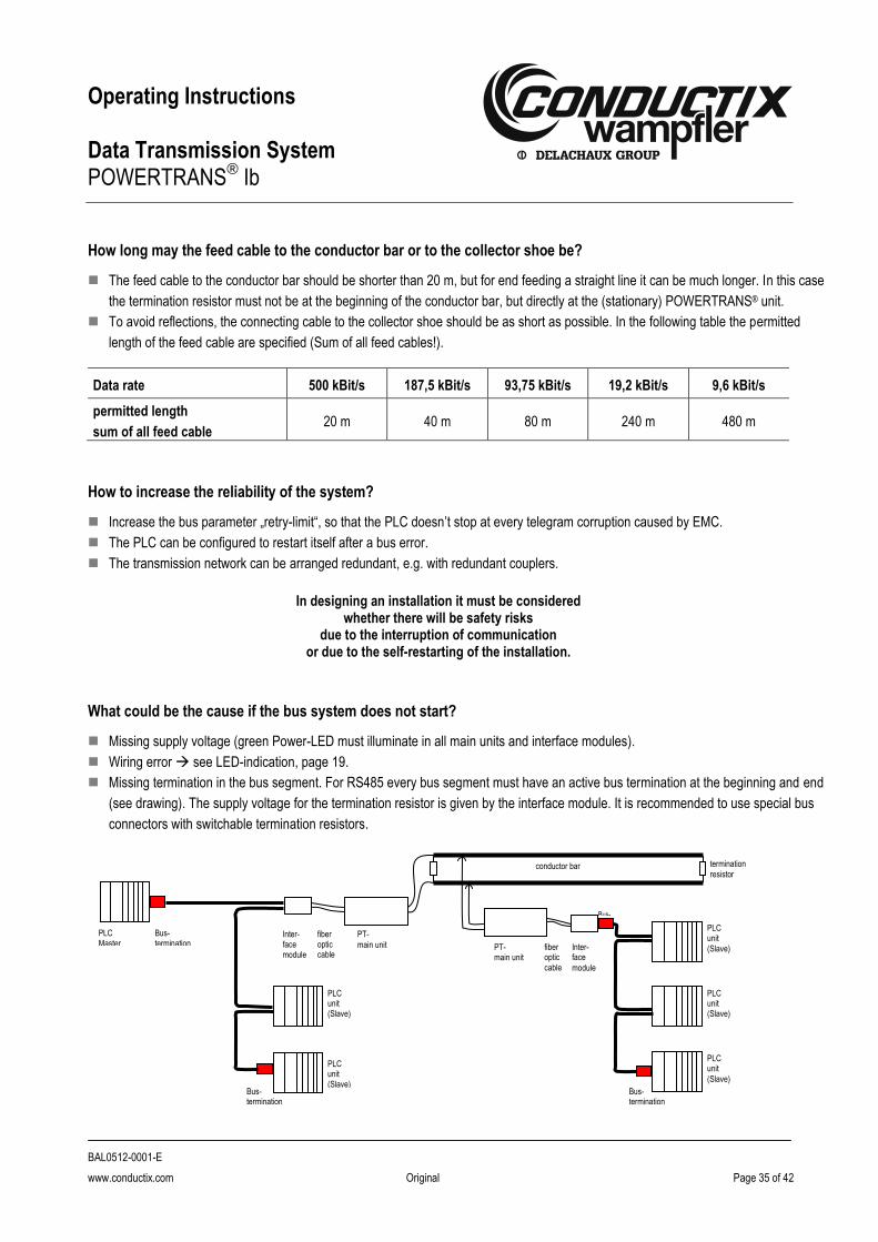
How long may the feed cable to the conductor bar or to the collector shoe be?
The feed cable to the conductor bar should be shorter than 20 m, but for end feeding a straight line it can be much longer. In this case
the termination resistor must not be at the beginning of the conductor bar, but directly at the (stationary) POWERTRANS® unit.
To avoid reflections, the connecting cable to the collector shoe should be as short as possible. In the following table the permitted
length of the feed cable are specified (Sum of all feed cables!).
Data rate 500 kBit/s 187,5 kBit/s 93,75 kBit/s 19,2 kBit/s 9,6 kBit/s
permitted length
sum of all feed cable 20 m 40 m 80 m 240 m 480 m
How to increase the reliability of the system?
Increase the bus parameter „retry-limit“, so that the PLC doesn’t stop at every telegram corruption caused by EMC.
The PLC can be configured to restart itself after a bus error.
The transmission network can be arranged redundant, e.g. with redundant couplers.
In designing an installation it must be considered
whether there will be safety risks due to the interruption of communication
or due to the self-restarting of the installation.
What could be the cause if the bus system does not start?
Missing supply voltage (green Power-LED must illuminate in all main units and interface modules).
Wiring error see LED-indication, page 19.
Missing termination in the bus segment. For RS485 every bus segment must have an active bus termination at the beginning and end
(see drawing). The supply voltage for the termination resistor is given by the interface module. It is recommended to use special bus
connectors with switchable termination resistors.
PLC Master
Inter- face module
fiber optic cable
PT-
main unit
termination
resistor
PT- main unit
fiber optic
cable
Inter- face
module
PLC unit
(Slave)
conductor bar
PLC unit (Slave)
PLC unit
(Slave)
PLC unit (Slave)
PLC unit (Slave)
Bus- termination
Bus- termination
Bus- termination
Bus-
termination
bus
cabl
e
bus
cabl
e

Operating Instructions Data Transmission System POWERTRANS
® Ib
BAL0512-0001-E
www.conductix.com Original Page 36 of 42
Is a parameterization of POWERTRANS® I necessary?
POWERTRANS® Ia: It is necessary to adjust the data rate and the mode full duplex or half duplex with jumpers (see Installation
instructions MV0512-0001 POWERTRANS® Ia).
POWERTRANS® Ib: No adjustments are needed.
Things to consider at start-up of the bus system
No, as soon as POWERTRANS® is ready (after. 5 ms), it sends and receives data. No start-up sequence has to be considered. The initialization of the bus occurs like a bus without POWERTRANS®.
What to consider when using interface converters, links or gateways?
The use of RS485 side termination resistors is imperative. The circuit is given in the catalog (KAT0512-0001).
The data rate over the POWERTRANS®-route could be different to those in the original bus system. Look for the specific data rate in
the data sheet of the interface converter, link or gateway.
At what temperatures can the devices operate?
Under operation the main unit could be 15°C above the ambient temperature. The maximum permissible ambient temperature is
50°C.
For the interface module an operating temperature of 60-70°C is usual.
What does a “POWERTRANS® segment” mean?
A maximum of 15 mobile units can operate together with one stationary device. For more than 15 units a segmentation of the installation is necessary (see drawing).
How many POWERTRANS® units can operate on one segment?
A maximum of 15 POWERTRANS® units may operate on one segment. For more units, segmentation is necessary (see above).
Bus system
segment 1 segment 2
bus termination
PT PT PT
Operating Instructions Data Transmission System POWERTRANS
® Ib
BAL0512-0001-E
www.conductix.com Original Page 37 of 42
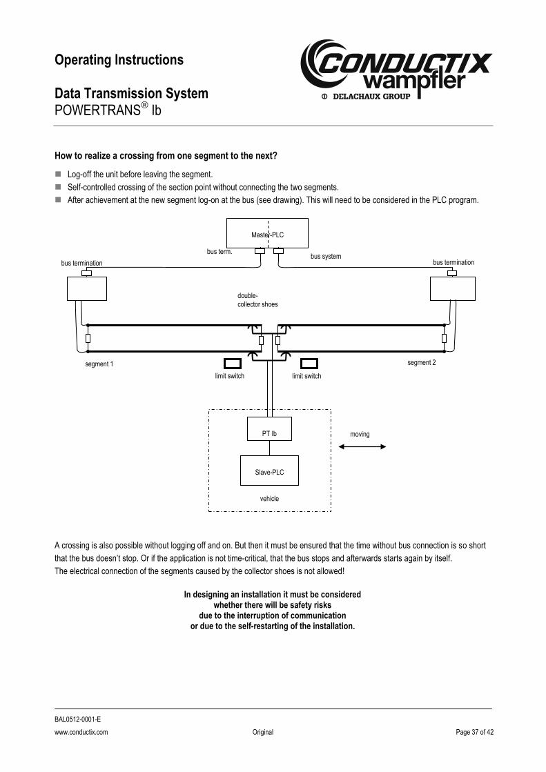
How to realize a crossing from one segment to the next?
Log-off the unit before leaving the segment.
Self-controlled crossing of the section point without connecting the two segments.
After achievement at the new segment log-on at the bus (see drawing). This will need to be considered in the PLC program.
A crossing is also possible without logging off and on. But then it must be ensured that the time without bus connection is so short
that the bus doesn’t stop. Or if the application is not time-critical, that the bus stops and afterwards starts again by itself.
The electrical connection of the segments caused by the collector shoes is not allowed!
In designing an installation it must be considered
whether there will be safety risks due to the interruption of communication
or due to the self-restarting of the installation.
bus termination
segment 1 segment 2
double-
collector shoes
limit switch limit switch
moving
PT Ib
PT Ib
PT Ib
Slave-PLC
vehicle
bus system
Master-PLC
bus termination
bus term.

Operating Instructions Data Transmission System POWERTRANS
® Ib
BAL0512-0001-E
www.conductix.com Original Page 38 of 42
What is to be considered in the change-over from POWERTRANS® Ia to POWERTRANS® Ib?
For POWERTRANS® Ia units, RS485 bus termination resistors are integrated within the devices, but for POWERTRANS® Ib the bus
termination resistors have to be externally mounted, in general with special bus connectors.
The interface module needs an additional supply voltage of 24 V.
An installation with POWERTRANS® Ia units can be extended with POWERTRANS® Ib units, that there is a mix of devices. The units
are compatible in their function.
POWERTRANS® Ia POWERTRANS® Ib with fiber optic and interface module
Are POWERTRANS® Ia und POWERTRANS® Ib units compatible?
Yes, the units are electrically compatible; POWERTRANS® Ib needs an additional supply voltage of 24 V.
What must be considered when extending an old installation?
POWERTRANS® Ia units are not sold as new parts any more. But exchange units are available.
Installations with POWERTRANS® Ia can be extended by POWERTRANS® Ib units.
It should be noted, that the POWERTRANS® Ib units have different dimensions and other connectors. An additional supply voltage of
24 V is necessary.
For POWERTRANS® Ib the bus termination resistors are externally connected, generally with special bus connectors.

Operating Instructions Data Transmission System POWERTRANS
® Ib
BAL0512-0001-E
www.conductix.com Original Page 39 of 42
Where do the termination resistors (at the high-voltage side) have to be connected?
POWERTRANS® I separates the bus in several segments. At every electrical end of a bus segment a bus termination resistor has to
be connected.
Which cable (between POWERTRANS® I and conductor bar) has to be used?
In general we do not prescribe the type of cable, but we recommend the use of shielded cable.
The installation was running a long time without problemss, but now there are more and more problems?
Aggressive ambient conditions, abrasion or dust could lead to contact problems at the collector shoes. Remedy: sandpaper the coals,
clean the conductor bar, e.g. with cleaning coals.
The collector shoes could be worn out. Remedy: exchange of the collector shoes.
If the problems are always in the same area: check the fixing and connection of the conductor bar. Check the contact pressure of the
collector shoes in this area.
Can security relevant data (e.g. e-stop) be transmitted with POWERTRANS® I?
The system is not qualified to transmit security relevant data. Required precautions needs to be realised by the planner with
suitable independent equipment.
PT
PLC wrong
PT
PLC correct
suggestion: connect termination resistor directly at Powertrans®I unit
PT
PLC correct
Operating Instructions Data Transmission System POWERTRANS
® Ib
BAL0512-0001-E
www.conductix.com Original Page 40 of 42
What to do if the system stops working?
Note the state of all LEDs and compare them with the table on page 17, and if possible, solve the problem.
Switch on unit per unit and observe where/when the failure occurs.
Swap POWERTRANS® I units pairwise and observe whether the failure remains or disappears.
Bypass the conductor bar with a cable to localize the cause.
Bypass POWERTRANS® I units with a bus cable to localize the cause.
Plug-off all POWERTRANS® I units and measure the resistance of the installation (high voltage side). At the mobile unit it is possible
to measure the resistance plus the transition resistance of the conductor bar. Reference value: 50…100 Ohms.
If the error cannot be found, contact the appropriate person at Conductix-Wampfler, or send an email to [email protected]
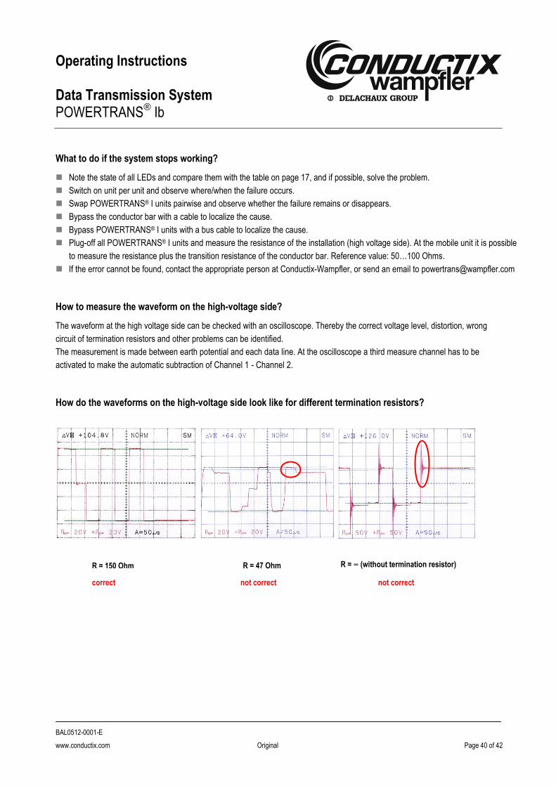
How to measure the waveform on the high-voltage side?
The waveform at the high voltage side can be checked with an oscilloscope. Thereby the correct voltage level, distortion, wrong
circuit of termination resistors and other problems can be identified.
The measurement is made between earth potential and each data line. At the oscilloscope a third measure channel has to be
activated to make the automatic subtraction of Channel 1 - Channel 2.
How do the waveforms on the high-voltage side look like for different termination resistors?
R = 150 Ohm R = 47 Ohm R = ∞ (without termination resistor)
correct not correct not correct

Operating Instructions Data Transmission System POWERTRANS
® Ib
BAL0512-0001-E
www.conductix.com Original Page 41 of 42
12 List of figures
Fig. 1 POWERTRANS® standard elements ....................................................................................................................... 8
Fig. 2 Dimensions of POWERTRANS® Ib ........................................................................................................................ 10
Fig. 3 Standard connection diagram ................................................................................................................................ 11
Fig. 4 Fixation of main unit and interface module ............................................................................................................. 13
Fig. 5 Configuration of the conductor rail (recommended) ............................................................................................... 14
Fig. 6 Measuring of the resistance ................................................................................................................................... 16
Fig. 7 Bus system with termination resistors .................................................................................................................... 17
Fig. 8 State of LEDs ......................................................................................................................................................... 18
Fig. 9 LEDs of system, numbers and characters corresponding to the table below ........................................................ 19
Fig. 10 Potential layout of a POWERTRANS® Ib system ................................................................................................... 20
Fig. 11 Measuring of the output signal ............................................................................................................................... 21
Fig. 12 Output level ............................................................................................................................................................ 21
Fig. 13 Retry Limit, step 1 .................................................................................................................................................. 22
Fig. 14 Retry Limit, step 2 .................................................................................................................................................. 22
Fig. 15 Electrical wiring, POWERTRANS® Ia ..................................................................................................................... 27
Fig. 16 Electrical wiring, POWERTRANS® Ib ..................................................................................................................... 27

Operating Instructions Data Transmission System POWERTRANS
® Ib
BAL0512-0001-E
www.conductix.com Original Page 42 of 42
Conductix-Wampfler AG
Rheinstrasse 27 + 33
79576 Weil am Rhein - Maerkt
Germany
Phone: +49 (0) 7621 662-0
Fax: +49 (0) 7621 662-144
www.conductix.com