Operating Instructions - Aptec Electronics · Operating Instructions Video Image Marker-Measurement...
146
Operating Instructions Video Image Marker- Measurement System Accuracy by Design VIA-170 ® P/N 700051 R
Transcript of Operating Instructions - Aptec Electronics · Operating Instructions Video Image Marker-Measurement...

OperatingInstructions
Video Image Marker-Measurement System
Accuracy by Design
VIA-170®
P/N 700051
R

ii

iii
VIA-170Video Image Marker-Measurement System
User's Manual
®
R

iv
Copyright© 1994-1998 by Boeckeler Instruments, Inc.,4640 South Butterfield Drive, Tucson, Arizona, U.S.A.85714; (520) 745-0001.
Boeckeler® and VIA-® are registered trademarks of BoeckelerInstruments, Inc., Tucson, Arizona. No part of this publication may bereproduced, transmitted, transcribed, stored in a retrieval system, ortranslated into any language in any form by any means without theexpressed written permission of Boeckeler Instruments, Inc.
Printed in the USA • P/N 700051 12/98

v
CONTENTS
LIST OF FIGURES ................................................. vi
Section One:Getting Started ...................................................... 1
INTRODUCTION .............................................. 3FEATURES ....................................................... 5
Video Image Marker ................................... 5Video Measurement .................................... 6
ADDITIONAL FEATURES ................................ 8COMPONENTS ................................................ 9
Keyboard Controller .................................... 9OPTIONAL COMPONENTS ........................... 12
Light Pen Controller .................................. 12Knob Controller ......................................... 14Joystick Controller .................................... 16Mouse/Mouse Pen Controller ................... 18Other Mouse Controllers ........................... 19
Section Two:Installation ........................................................... 21
INSTALLATION .............................................. 23Composite Systems .................................. 23RGB Systems ........................................... 26Y/C Systems ............................................. 27
INSTALLATION FOR OPTIONAL LIGHTPEN EXTENSION ........................................... 29
Section Three:Video Marking ...................................................... 31
OVERVIEW .................................................... 33USING THE MARKER KEYS.......................... 34
General Marking Procedure ...................... 35Marker Keys .............................................. 36
USING THE ACTION KEYS IN MARKING ..... 46
Section Four:Video Measuring .................................................. 51
OVERVIEW .................................................... 53
THE MEASUREMENT MODE ........................ 54USING THE MEASUREMENT KEYS ............. 56
General Measuring Procedures ................ 57Measurement Keys ................................... 58
USING THE ACTION KEYS IN MEASURING 61CALIBRATION ................................................ 70
General Calibration Procedures ............... 71MEASURING .................................................. 78
Basic Operation ........................................ 78X-Axis Measurement ................................ 79Y-Axis Measurement ................................ 81X and Y Measurement .............................. 84Point-to-Point Measurement ..................... 87Angle Measurement .................................. 89Circle Measurement .................................. 95Count Measurement ................................. 98Area/Chords Measurement ..................... 101Timers ..................................................... 107
Section Five:Communication ................................................. 111
USE OF THE RS-232 PORT ........................ 113Basic Operation ...................................... 113Set Up ..................................................... 114Transmitting Data ................................... 115Program to Test Port .............................. 116RS-232 Connector Pin Out ..................... 117Using a Video Printer .............................. 118
Section Six:Appendices ....................................................... 119
TROUBLESHOOTING GUIDE...................... 121WARNING MESSAGES ............................... 123GLOSSARY .................................................. 125ABOUT BOECKELER INSTRUMENTS ........ 130INDEX ......................................................... 131

vi
LIST OF FIGURES
Figure 1.1VIA-170 Keyboard Controller ............................ 9
Figure 1.2LP-32 Light Pen Controller ............................. 12
Figure 1.3KS-30 Knob Controller .................................... 14
Figure 1.4JS-40 Joystick Controller ................................ 16
Figure 1.5MP-30 Mouse Pen Controller ......................... 18
Figure 2.1Back Panel of VIA-170 (for composite videosystems) ......................................................... 23
Figure 2.2VIA-170 Sample Copyright Message .............. 25
Figure 2.3Back Panel of VIA-170 (for RGB, Y/C) ........... 26
Figure 2.4RGB Interface and Y/C Interface .................... 27
Figure 2.5Sample Copyright Message ............................ 28
Figure 2.6Configuration for the LPX Light Pen Ext. ........ 29
Figure 3.1A combination of VIA-170 graphics. ............... 33
Figure 3.2VIA-170 Keyboard Controller .......................... 34
Figure 3.3Creating a Custom Ruler or Reticle ................ 37
Figure 3.4Light Pen Calibration Menu ............................ 42
Figure 3.5Set Color Palette Menu................................... 44
Figure 3.6Set Menu Colors Menu ................................... 44
Figure 4.1The XY Measurement Mode, StatisticsMode Active .................................................... 55
Figure 4.2VIA-170 Keyboard Controller .......................... 56
Figure 4.3The Statistics Table ........................................ 69
Figure 4.4First Calibration Menu..................................... 71
Figure 4.5Second Calibration Menu ............................... 72
Figure 4.6Third Calibration Menu ................................... 73
Figure 4.7Calibration: X-axis Line Placement ................. 76
Figure 4.8Calibration: Y-axis Line Placement ................. 77
Figure 4.9X Measurement Mode .................................... 79
Figure 4.10Positioning the X-Axis Measuring Lines ......... 80
Figure 4.11Y Measurement Mode .................................... 82
Figure 4.12Positioning the Y-axis Measurement Lines ..... 83
Figure 4.13XY Measurement Mode .................................. 84
Figure 4.14Positioning the X and Y Measurement Lines .. 85
Figure 4.15P-P Measurement Mode ................................. 87
Figure 4.16Positioning the Point-to-Point Cursors ............ 88
Figure 4.17ANGLE Mode .................................................. 90
Figure 4.18ANGLE Mode, Placing the First Leg ............... 91
Figure 4.19ANGLE Mode, Placing the Second Leg .......... 92
Figure 4.20Measuring Other Angles When OneAngle is Known ............................................... 93
Figure 4.21Measuring an Angle Using Three Points ........ 94
Figure 4.22CIRCLE Measurement Mode .......................... 95
Figure 4.23CIRCLE Mode: Anchoring the Third Point ...... 96
Figure 4.24Count Mode .................................................... 98
Figure 4.25Counting Objects, Group A ............................. 99
Figure 4.26
vii
Combination of Tags ..................................... 100Figure 4.27
Drawing Perimeter of Area ........................... 101Figure 4.28
Area Measurement Option ............................ 102Figure 4.29
Calculating the Area ..................................... 103Figure 4.30
Chord Measurement Option ......................... 104Figure 4.31
Measuring the D1 Chord ............................... 105Figure 4.32
Measuring the D2 Chord ............................... 106Figure 4.33
Timer w/ XY Measurement ........................... 107Figure 4.34
Timer w/ Markers Mode ................................ 108Figure 5.1
RS-232 Setup Menu ..................................... 114


Section One:Getting Started

2 - Getting Started Boeckeler VIA-170
Boeckeler VIA-170 Getting Started - 3
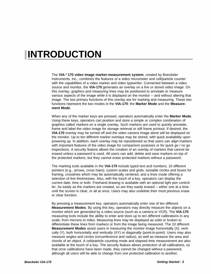
INTRODUCTION
The VIA-® 170 video image marker-measurement system , created by BoeckelerInstruments, Inc., combines the features of a video micrometer and cell/particle counterwith the capabilities of a video marker and video typewriter. Connected between a videosource and monitor, the VIA-170 generates an overlay on a live or stored video image. Onthis overlay, graphics and measuring lines may be positioned to annotate or measurevarious aspects of the image while it is displayed on the monitor -- and without altering thatimage. The two primary functions of this overlay are for marking and measuring. These twofunctions represent the two modes in the VIA-170: the Marker Mode and the Measure-ment Mode .
When any of the marker keys are pressed, operators automatically enter the Marker Mode .Using these keys, operators can position and store a simple or complex combination ofgraphics called markers on a single overlay. Such markers are used to quickly annotate,frame and label the video image for storage retrieval or still frame printout. If desired, theVIA-170 overlay may be turned off and the video camera image alone will be displayed onthe monitor. Up to ten different marker overlays may be stored, with quick availability uponpowering up. In addition, each overlay may be repositioned so that users can align markerswith important features of the video image for comparison purposes or for quick go / no goinspections. A security feature allows the creation of an overlay of markers that cannot beerased unless a password is used. All users can add, delete and save markers on top ofthe protected markers, but they cannot erase protected markers without a password.
The marking tools available in the VIA-170 include typed text and numbers, 10 differentpointers (e.g., arrows, cross hairs), custom scales and grids, sizeable circles and boxes forframing, crosslines which may be automatically centered, and a lines mode offering aselection of line thicknesses. Also, with the touch of a key, operators can display thecurrent date, time or both. Freehand drawing is available with an optional light pen control-ler. As easily as the markers are created, so are they easily erased -- either one at a timeuntil the screen is clear, or all at once. Users may also undelete their most previous eraseor clear function.
By pressing a measurement key, operators automatically enter one of ten differentMeasurement Modes . By using this key, operators may directly measure the objects on amonitor which are generated by a video source (such as a camera or VCR). The VIA-170measuring tools include the ability to enter and store up to ten different calibrations in anyscale, from microns to miles. Measuring lines may be displayed as solid or broken todifferentiate these lines from markers or from the image being measured. The 10 differentMeasurement Modes assist users in measuring the monitor image horizontally (X), verti-cally (Y), both horizontally and vertically (XY) or diagonally (point-to-point). Users may alsomeasure angles and circles (circumference and radius), as well as measure the area andchords of an object. A cell/particle counting mode and elapsed time measurement are alsoavailable at the touch of a key. The security feature allows protection of all calibrations, sothat once calibrations have been made, they cannot be changed without a password,although all users will be able to change from one protected calibration to another.

4 - Getting Started Boeckeler VIA-170
Once in a Measurement Mode , users may select whether to measure with or without theability to enter measurements into a Statistics Table . This table can contain up to 500measurement values and display calculations for the count, mean, high value, low value,and standard deviation. Statistics and measurements can be output as ASCII data via anRS-232 serial port for use with computers or printers.
While measuring or marking, users are aided with the availability of on screen help. A briefdemonstration of features is also offered, should a quick overview of the VIA-170 beneeded in training other users.
Standard components of the VIA-170 include a keyboard controller. Optional featuresinclude an LP-32 light pen which adds freehand drawing and path length features to theVIA-170. Also available is the KS-30 knob controller or JS-40 joystick controller, bothergonomically designed for ease in fine measuring. The VIA-170 is also compatible withMSTM and Microsoft TM mouse devices.
The VIA-170 is compatible with most common video standards, including monochrome RS-170 and color NTSC composite cameras, monitors, recorders, video presentation productsand other NTSC video equipments. Boeckeler video interfaces may be purchased to createbrightly colored marker overlays for use with Y/C (S-Video) or RGB video equipment. Anexport model of the VIA-170 is compatible with European CCIR and PAL video standards.

Boeckeler VIA-170 Getting Started - 5
FEATURES
•Ten marking tools (in keyboard order):
1. Typed Text Label video images for video print, still image recorder or projectiondisplay. Useful in record keeping, presentations, video confer-ences, meetings and more. Upper and lower case characters areavailable and positionable anywhere on screen.
2. Pointers 10 different pointers can assist in marking a video image to pointout important aspects of the image under study. Pointers includefour different arrows, standard cross hairs, pointed cross hairs, atarget circle, a small circle, a target box and a small box. Each arepositionable anywhere on screen.
3. Grids Custom grids may be created in horizontal, vertical or box patterns(horizontal and vertical).
4. Scales Size and position scales to create reticles for dimensional mea-surements or subdivide scales with cross hairs for fine measure-ments. Sizeable horizontal and vertical scales available.
5. Circles Sizeable circles and ellipses may be placed anywhere on screen.
6. Boxes Sizeable boxes or rectangles may be placed anywhere on screen.
7. Crosslines Crosslines can be automatically centered and fixed, or customdesigned. Horizontal and vertical lines can be displayed in avariety of line patterns, including scaled, dotted, dashed and solid.Intersections can be displayed open or closed.
8. Lines Horizontal, vertical or diagonal lines may be positioned in one ofthree different line thickness selections.
9. Date/Time Set the date and time, then place the label anywhere on thescreen. The date/time label will remain active even after theVIA-170 is powered down.
10. Draw With the optional LP-32 light pen or other mouse controller, userscan draw or write over the video image. Autointercept option allowsusers to easily close a drawing before measuring the area of thatdrawing.
VIDEO IMAGE MARKER

6 - Getting Started Boeckeler VIA-170
• Align Mode allows users to position markers in unison over important aspects of thevideo image. Marker alignment assists in quickly comparing features of objects beinginspected or studied.
• On screen display of marker width and height or length as users size the box, circle,scale, grid, or crossline markers. Display of path length is shown while creating straightlines. With optional drawing devices, path length can be displayed as freehand lines aredrawn.
• On screen display of marker position .
• Battery backed up memory allows many different markers to be combined and stored inten different overlays, each of which can be recalled even after the unit has been pow-ered down.
• Easy adjustment of gray level or color of markers for optimal contrast with the videoimage (color markers will be displayed only if an optional VIA-RGB or VIA-Y/C interfaceis being used).
• Hide or show stored markers with the touch of a key to instantly view the video imagealone or with the markers.
• Erase markers from the overlay all at once or one at a time. An Undelete option allowsusers to undo their most recent erase or clear.
• Protect marker overlays when desired, so that certain markers cannot be erased unlessa password is entered. Other users may add markers to the protected overlay, and theseadded markers can be erased, but the protected markers cannot be erased.
• Separate X-axis and Y-axis calibration ensures accuracy of all measurements.
• Ten calibrations may be set up and stored for multiple measurements. Each set up islabelled and accessible from the working screen.
• Nonvolatile memory stores and recalls all calibrations even after the unit has beenpowered down.
• Protect calibrations when desired, so that once calibrations have been set, they cannotbe altered without entering a password. Operators can change from one protectedcalibration to another.
• 10 Measurement Modes :
1. Horizontal, X Operators move two vertical lines to each edge of anobject. The measurement is continuously displayed on screen.
2. Vertical, Y Operators move two horizontal lines to the top and bottomedge of an object. The measurement is continuously displayedon screen.
3. 2-dimensional, X-Y Operators position two horizontal and two vertical lines at theedges of an object. X and Y measurements are continuouslydisplayed on screen.
VIDEO MEASUREMENT

Boeckeler VIA-170 Getting Started - 7
4. Point-to-Point, P-P Operators place two cross hairs at points to be measured onthe object. The distance between the two points is continuouslydisplayed on the screen.
5. Angles Operators place two or more points to define each leg of anangle. The degree of the angle formed by the legs is displayedon the screen, whether or not the vertex of the angle isapparent. Users can turn on or off a graphic display of theangle as it is being measured.
6. Circles Operators place three or more points along the perimeter of acircular image. The radius and circumference of the circle aredisplayed on the screen, even when only part of the circle is inthe field of view. Users can turn on or off a graphic display ofthe circle as it is being measured.
7. Count Operators position a tag and drop it over each cell or particle tobe counted. Hundreds of particles may be counted, and eachmay be tagged with one of 10 letters (A-J), which preventsaccidental recounting and allows operators to count up to 10different types of particles visible in a field of view.
8. Area Operators fill a closed graphic (or freehand drawing with anoptional light pen or mouse device). The area of the closedshape is instantly calculated and continuously displayed onscreen with the image.
9. Chord Operators place cursors on the extreme points of the object'sperimeter to obtain the long chord, and at narrow points of theperimeter to obtain the short chord. The two distances aredisplayed on screen continuously along with the area.
10. Timer A timer may be started and stopped to measure an eventwhich takes place on the screen, either in the Marker Mode orin one of the four linear measurement modes ( X, Y, XY, andPoint-to-Point). Time is continuously displayed to thehundredths of a second and may be used to track a singleevent up to 99 hours.
• Statistics Mode in which displayed measurements can be entered into a StatisticsTable . Up to 500 measurements can be stored in the table, which also displays thecurrent count, mean, standard deviation, low value, high value and range. Statisticalcalculations change as each new measurement is added or deleted in the table.
• RS-232 data output transmits ASCII measurement data and statistics to printers orcomputers.
• The ability to change the gray level or color of measuring lines for optimum contrastwith the video image.
• The ability to view the camera image alone without a measurement overlay. Operatorsmay also choose between viewing the image with measuring lines only or with measuringlines and markers.
• The ability to select solid or dashed measuring lines to aid in differentiating measuringlines from the camera image or from the markers.

8 - Getting Started Boeckeler VIA-170
ADDITIONAL FEATURES
• On screen Help can be accessed at any time during measuring or marking.
• A Demonstration of Features can be activated to briefly show the various measuringand marking functions of the VIA-170 should a quick overview be needed in training otherusers.

Boeckeler VIA-170 Getting Started - 9
COMPONENTS
KEYBOARD CONTROLLERThe keyboard is the user's primary interface with the VIA-170. Figure 1.1 below depicts theVIA-170 keyboard controller. In general, the keyboard is used to select, type, position, saveand erase the markers on the video overlay. The keyboard is also used to calibrate andmeasure as well as guide the user through menu selections. A few of these functions mayalso be controlled with a separately purchased light pen, joystick or knob controller, mousepen or other mouse controllers (refer to "Optional Components " on page 12). Generaldefinitions of each function key on the keyboard follow.
MARKER KEYS(Graphics)
ACTION KEYS
MARKER KEYS(Text/Numbers)
MEASUREMENT KEYS
Figure 1.1VIA-170 Keyboard Controller
Keyboard Controller Definitions
MARKER KEYS(Graphics)
These keys allow operators to select the graphics or markersdesired and the appearance of those markers. Such keys include POINTERS [F1] , SCALES/GRIDS [F2] , SHAPES [F3] ,CROSSLINES [F4] , LINES [F5] , DRAW [F6] , SHOW DATE/TIME[F7] and CHANGE COLOR [F8] . Auxiliary functions which supportthese keys are activated by pressing CTRL + a marker key . Auxil-iary marker keys are those for SHOW MARKER SIZE/COORDS,SIZE OBJECTS/TEXT , ALIGN, CALIBRATE LIGHT PEN, SETDATE/TIME and SET COLOR & BRIGHTNESS .

10 - Getting Started Boeckeler VIA-170
Text and number keys on the VIA-170 keyboard controller performas alphanumeric labels or markers which are immediately typed onthe screen when pressed. Upper and lower case characters areavailable. Each line of type may be freely positioned on the overlayuntil selected or anchored.
As the name suggests, measurement keys activate the measuringcapabilities of the VIA-170, so that vertical, horizontal, point-to-point,angle or circle measurement, count, area, chords, and elapsed timemeasurements may take place on any video image with or without aselected marker overlay. Such keys include XY MEASURE [F9];ANGLES/CIRCLES [F10]; COUNT [F11]; AREA/CHORDS [F12] .
Auxiliary functions which support these keys are activated by press-ing CTRL (or ALT) + a measurement key . Auxiliary measurementkeys are those for CHANGE LINE PATTERN , CLEAR POINTS ,TIMER W/XY MEASUREMENT, TIMER w/MARKERS , MEASUREW/STATISTICS.
Action keys perform an action with regard to marking or measuring,such as moving to the next or previous overlay, erasing a marker,positioning and anchoring a marker or positioning cursors andmeasurement lines. These keys include ALL GRAPHICS ON/OFF[Esc], RS-232C TRANSMIT [Print Screen], SELECT CALIBRA-TION # [Scroll Lock], HELP [Pause/Break], the ENTER key,ENTER STATISTICS [Insert] , OVERLAY [Home] , PREV OVERLAY[Page Up] , UNDO [Delete] , CLEAR [End] , NEXT OVERLAY [PageDown] , CTRL, and the four POSITIONING keys (left, right, up anddown).
Auxiliary functions which support these keys are activated by press-ing CTRL, ALT or SHIFT + an action key . Auxiliary action keys arethose for SECURITY MENU, SET RS232, CALIBRATE , DEMO OFFEATURES, AUTOINTERCEPT WHILE DRAWING , CLEAR OFF-SET CREATED IN ALIGN MODE , CLEAR STATISTICS TABLE ,POSITION/SIZE in FINER INCREMENTS , REVERSE TOGGLE,SHOW/HIDE ANGLE WHILE MEASURING , SHOW/HIDE CIRCLEWHILE MEASURING , STATISTICS TABLE , UNDELETE.
MARKER KEYS(Text/Numbers)
MEASUREMENTKEYS
ACTION KEYS
Positioning MarkersWhen operating the VIA-170 with the keyboard controller, the active markers may bepositioned vertically by pressing the up and down POSITIONING keys. Pressing the rightand left POSITIONING keys moves the marker horizontally. Once the marker is positioned,operators may anchor and store the marker in the overlay by pressing the ENTER key.
POSITIONING keys are not only used for positioning markers, but also for sizing the activemarkers before they are anchored. For sizing instructions refer to instructions on page 39.

Boeckeler VIA-170 Getting Started - 11
Positioning Measuring Lines or CursorsWhen operating the VIA-170 with the keyboard controller, measuring lines and cursors maybe moved anywhere on the screen by pressing the POSITIONING keys which direct right,left, up and down movement. These keys are located to the right of the ENTER key. Forfine movement, press the CTRL key along with one of the positioning keys.
While measuring, the POSITIONING keys are used to position measuring lines or mea-surement cursors. Left and right keys move vertical lines left and right. Up and down keysmove horizontal lines up and down. When measuring, only the top and/or left lines will beactive. To activate the right and bottom lines, press ENTER. When measuring angles,pressing the SPACE BAR will begin definition of either the first or second leg of the angle.
Moving through MenusWhen users are presented with menus, they may move through the options and entryblanks by pressing any of the appropriate POSITIONING keys. In some cases, users willbe asked to toggle through options by pressing the SPACE BAR . Pressing ENTER selectsthe displayed option.

12 - Getting Started Boeckeler VIA-170
OPTIONAL COMPONENTS
LIGHT PEN CONTROLLERFigure 1.2 below depicts the LP-32 Light Pen Controller. The controller functions as anauxiliary interface with the VIA-170. In general, the pen is used like a writing utensil, and ispressed against the screen to position markers or to freehand draw or write directly on themonitor. Broad definitions of the light pen button functions are listed below. Refer to thissection, if needed, when general instructions later in the manual ask users to anchor amarker, to position a cursor or to draw.
Figure 1.2LP-32 Light Pen Controller
TIP BUTTON
BARREL BUTTON
a button which positions active markers, measurement lines andmeasurement cursors when lightly dragged across the screen. Alsodraws on the screen when the DRAW [F6] key is activated and thepen tip is pressed into the screen while drawing. Quickly clicking theTip Button into the screen anchors active markers or measurementcursors. In the Area/Chords Mode , clicking the pen tip in the dataline activates measurement in the Area or Chords Mode . The lightpen is not active in making menu selections.
zeroes out the display of path length while users are freehanddrawing.

Boeckeler VIA-170 Getting Started - 13
Positioning Measuring Lines or CursorsWhen operating the VIA-170 with the light pen controller, the measuring lines or cursorsmay be moved anywhere on the screen by lightly dragging the light pen across the screen.The marker, measuring line or cursor will follow this movement at a specified offset. Forexample, "dragging" the pen to the left on the screen will correspondingly move the mea-suring line or cursor to the left on the screen, one inch away from the pen tip if the offsetwas calibrated at one inch (for calibration instructions follow the procedure above).
While measuring, the light pen may be used to quickly position measuring lines cursors.When first measuring, only the top and/or left lines will be active. To activate the right andbottom lines, press ENTER on the keyboard, then continue with the light pen.
NOTE: The measuring lines may shift as the pen approaches the screen. For thisreason, Boeckeler recommends that light pens be used for positioning markersrather than for positioning measuring lines.
Moving through MenusExcept for activating one of three measuring modes in the Area/Chords Data Line , orchanging the count tag in the Count Data Line , the light pen has no effect in menu selec-tions. Use the keyboard POSITIONING keys to maneuver within menus.
When operating the VIA-170 with the light pen controller, the active marker may be movedanywhere on the screen by lightly dragging the light pen across the screen. The marker willfollow this movement at a specified offset. For example, "dragging" the pen to the left onthe screen will correspondingly move the marker to the left on the screen, one inch awayfrom the pen tip if the offset was calibrated at one inch (calibration instructions follow).Pressing the pen into the screen will anchor an active graphic. Dragging the pen tip acrossthe screen also serves to quickly size a marker if users have activated the sizing mode bypressing the SIZE OBJECTS/TEXT (CTRL + SHAPES [F3]) . If precise sizing is desired,operators should use the keyboard POSITIONING keys instead of the light pen.
Drawing is accomplished similarly to positioning markers, except instead of dragging thepen tip across the screen, users will press the Tip Button into the screen and draw. Again,the drawing line will be offset from the pen tip in accordance to how the pen was calibrated.
To Calibrate the Light Pen :
1. Press the CTRL key together with the DRAW [F6] key until the light pen calibrationscreen appears displaying a calibration menu.
A cross hairs cursor will appear on the screen along with menu instructions.
2. Press any function key to exit calibration at this point, without making changes.
3. If the user wishes to continue calibration, press the Tip Button directly on the cursor forno offset margin. Or press the Tip Button at a desired distance from the cursor to createan offset margin.
The offset margin is now automatically stored and the offset mode has been exited.
Positioning and Sizing Markers

14 - Getting Started Boeckeler VIA-170
KNOB CONTROLLERAlthough the VIA-170 operates primarily with the standard keyboard controller, for finemeasurement and positioning the KS-30 Knob Controller is recommended (refer to Figure1.3). The knob controller operates simultaneously with the keyboard controller and canoperate simultaneously with optional light pen. In general, the knobs are used to quicklysize and move the markers or quickly position measuring lines or measurement cursors onthe VIA-170 overlay. Broad definitions of the five keys on the knob controller are listedbelow. Refer to this section, if needed, when general instructions later in the manual askusers to position measuring lines or size and anchor a marker.
Knob Controller Key Definitions
AXIS a switch which specifies the axis or point which the knobs currentlycontrol.
SELECT a button which anchors the active marker in its current position.
DATA zeroes out path length (distance display) while drawing with lightpen or mouse. In Measuring w/Statistics Mode , enters displayedmeasurement into the Statistics Table .
COMPARE a switch which fixes the distance between the measuring lines sothat the lines may be moved in unison when in X, Y, or XY Mode ;inactive in P-P Mode ; ANGLES/CIRCLES Mode; COUNT Mode;AREA/CHORDS Mode , and TIMER.
TRANSMIT a button which downloads current measurement readings, markercoordinates, and statistics through the RS-232C serial port. Suchdata must be displayed before being transmitted.
Figure 1.3KS-30 Knob Controller
When operating the VIA-170 with the knob controller, the active markers may be positionedvertically by rotating the LEFT KNOB. Clockwise rotation moves the marker toward the
Positioning and Sizing Markers

Boeckeler VIA-170 Getting Started - 15
bottom of the screen. Counterclockwise rotation moves the marker toward the top. Rotatingthe RIGHT KNOB moves the marker horizontally. Clockwise rotation moves the marker tothe right side of the screen. Counterclockwise rotation moves the marker toward the leftside of the screen. Once the marker is positioned, operators may anchor and store themarker in the overlay by pressing the SELECT button. Drawing can only take place with theoptional light pen or mouse device.
Sizing markers with the knob controller can be accomplished after pressing the keyboardSIZE OBJECTS/TEXT (CTRL + SHAPES [F3]) key. The LEFT KNOB makes the objecttaller or shorter. The RIGHT KNOB makes the object wider or narrower. After objects aresized, users can save the size by pressing the SELECT button on the knob controller.Positioning of the sized object may now take place.
When measuring with the knob controller, the knobs are used to position measuring linesand measuring cursors.
While measuring in the X Mode , the left measuring line is controlled by the LEFT KNOB .The right line is controlled by the RIGHT KNOB . To move both of the lines in unison, pressthe knob controller's COMPARE SWITCH to the ON position.
While measuring in the Y Mode , the top measuring line is controlled by the LEFT KNOB .The bottom measuring line is controlled by the RIGHT KNOB . To move both of the lines inunison, press the knob controller's COMPARE SWITCH to the ON position.
While measuring in the XY Mode , the left measuring line is controlled by the LEFT KNOB .The right measuring line is controlled by the RIGHT KNOB . To activate the top and bottomlines, place the AXIS switch in the P2 position. To move parallel lines in unison, press theknob controller's COMPARE SWITCH to the ON position.
When measuring in the P-P Mode (point-to-point), the left cross hairs cursor is activated byplacing the AXIS switch in the P1 position. Rotate the LEFT KNOB to position the cursorvertically and the RIGHT KNOB to position the cursor horizontally. Then place the AXISswitch in the P2 position to activate the second cursor. Rotate the LEFT KNOB to positionthe point vertically and the RIGHT KNOB to position the point horizontally.
When measuring in the ANGLE Mode or CIRCLE Mode , the first cross hairs cursor willappear on screen alone. Rotate the LEFT KNOB to position the cursor vertically and theRIGHT KNOB to position the cursor horizontally. When the cursor is positioned on thescreen, press SELECT. The first cursor will be anchored in place and the second crosshairs cursor will appear, ready for positioning. Follow this procedure until all cross hairscursors are anchored. It does not matter whether the AXIS switch is in the P1 or P2 posi-tion while in these modes.
When measuring in the AREA/CHORDS or COUNT Mode , the cursors or alphanumericletters are positioned individually, one at a time. Rotate the LEFT KNOB to position thecursor or active letter vertically, and the RIGHT KNOB to position the cursor or letterhorizontally. When the cursor is positioned on the screen, press SELECT. In AREA Mode ,the area enclosed around the cursor will fill. In CHORDS Mode and COUNT Mode the firstcursor/letter will be anchored in place and the second cursor/letter will appear, ready forpositioning. It does not matter whether the AXIS switch is in the P1 or P2 position while inthese modes. It does not matter whether the COMPARE switch is on or off.
Positioning Measuring Lines or Cursors

16 - Getting Started Boeckeler VIA-170
Moving through MenusExcept for activating one of three measuring modes in the Area/Chords Data Line , theknob controller has no effect in menu selections. Use the keyboard POSITIONING keysinstead.
JOYSTICK CONTROLLERThe VIA-170 may operate with either the joystick or knob controller while the keyboardcontroller is connected. If all three controllers are connected, the VIA-170 will automaticallydefault to the joystick controller. Figure 1.4 below depicts the JS-40 Joystick Controller.This controller functions as the user's auxiliary interface with the VIA-170. In general, thejoystick is used to position markers and measuring lines on the overlay. Broad definitions ofthe three keys on the joystick controller are listed below. Refer to this section, if needed,when general instructions later in the manual ask users to position measuring lines or sizeand anchor a marker.
SELECT a button which anchors the active marker in its current position.Also selects which measuring line or cursor will be activated forpositioning.
DATA zeroes out path length (distance display) while drawing with lightpen or mouse. In Measuring w/Statistics Mode , enters displayedmeasurement into the Statistics Table .
TRANSMIT a button which downloads displayed measurements or displayedmarker size and coordinates through the RS-232C serial port.
When operating the VIA-170 with the joystick controller, the active markers may be posi-tioned vertically by tilting the joystick forward or backward. Tilting the joystick forwardmoves the marker toward the top of the screen. Tilting the joystick backward (toward the
Figure 1.4JS-40 Joystick Controller
Positioning and Sizing Markers

Boeckeler VIA-170 Getting Started - 17
Except for activating one of three measuring modes in the Area/Chords Data Line , thejoystick controller has no effect in menu selections. Use the keyboard POSITIONING keysinstead.
Moving through Menus
operator) moves the marker toward the bottom of the screen. Tilting the joystick rightmoves the marker to the right side of the screen. Tilting the joystick left moves the markertoward the left side of the screen. Once the marker is positioned, operators may anchor andstore the marker in the overlay by pressing the SELECT button. Drawing can only takeplace with the optional light pen or mouse device.
Sizing markers with the joystick controller can be accomplished after pressing the keyboardSIZE OBJECTS/TEXT (CTRL + SHAPES [F3]) key. Tilting the joystick forward and back-ward makes the object taller or shorter. Tilting the joystick left and right makes the objectwider or narrower. After objects are sized, users can save the size by pressing the SELECTbutton on the joystick. Positioning of the sized object may now take place.
When measuring with the joystick controller, tilting the joystick positions measuring linesand measuring cursors.
While measuring in the X Mode , the vertical measuring lines are controlled by tilting thejoystick to the left and right. To move the lines individually, press the SELECT button whiletilting the joystick to the left or right.
While measuring in the Y Mode , the horizontal measuring lines are controlled by tilting thejoystick forward and backward. To move a line independent of the other, press the SELECTbutton while tilting the joystick forward or backward.
While measuring in the XY Mode , the horizontal measuring lines are controlled by tilting thejoystick forward and backward, and the vertical measuring lines are controlled by tilting thejoystick to the left and right. To move a line independent of the other, press the SELECTbutton while tilting the joystick.
When measuring in the P-P Mode (point-to-point), one cross hairs cursor will move. Tomove the other cross hairs cursor, press the SELECT button and tilt the joystick forward orbackward, left or right, or diagonally.
When measuring in the ANGLE Mode or CIRCLE Mode , the first cross hairs cursor willappear on screen alone. Tilt the joystick forward or backward to position the cursor verti-cally and tilt the joystick left or right to position the cursor horizontally. When the cursor ispositioned on the screen, press SELECT. The first cursor will be anchored in place and thesecond cross hairs cursor will appear, ready for positioning. Follow this procedure until allcross hairs cursors are anchored.
When measuring in the AREA/CHORDS or COUNT Mode , the cursors or alphanumericletters are positioned individually, one at a time. Tilt the joystick forward or backward toposition the cursor or letter vertically, and tilt the joystick left or right to position the cursor orletter horizontally. When the cursor is positioned on the screen, press SELECT. In AREAMode , the area enclosed around the cursor will fill. In CHORDS Mode and COUNT Mode ,the first cursor/letter will be anchored in place and the second cursor/letter will appear,ready for positioning.
Positioning Measuring Lines or Cursors

18 - Getting Started Boeckeler VIA-170
MOUSE PEN OR MOUSE CONTROLLERFigure 1.5 below depicts an optional mouse pen controller. The mouse pen (or other MSTM
or MicrosoftTM mouse device) functions as the user's auxiliary interface with the VIA-170. Ingeneral, the mouse pen is used to draw, write and position active markers or measurementlines on the video screen by tracing the pen on the mouse pad or other smooth surface(some operators even use the sides of their legs). This allows users to mark on the monitorat a distance. The mouse pen can also be used to anchor and size markers on the screen,which is also a keyboard function. Definitions of the three keys on the mouse pen arediscussed below. Refer to this section, if needed, when general instructions later in themanual ask users to position lines or anchor a marker.
Figure 1.5MP-30 Mouse Pen Controller
SELECTBUTTON #1
SELECTBUTTON #2
SPEEDSWITCH
TRACK BALL
SELECTBUTTON #1 (or First Button) a button which anchors the active marker in its
current position. Also selects which measuring line or cursor will beactivated for positioning. While in the DRAW mode , this button ispressed as the pen is "drawn" across the mouse pad. A drawingline will be displayed accordingly on screen.
SELECTBUTTON #2 (or Second Button) zeroes out the display of path length while
users are freehand drawing.
SPEEDSWITCH switches the speed of the mouse pen track ball from slow to fast.
TRACK BALL moves the cursor, active markers or measurement lines anywhereon the screen according to how the ball is rolled across a smoothsurface.
Positioning and Sizing Markers
When operating the VIA-170 with the mouse pen controller, the active marker may bemoved anywhere on the screen by lightly dragging the mouse pen across a smooth surface(such as a mouse pad or the side of one's leg). The marker will follow this movement. Forexample, dragging the pen to the left will correspondingly move the marker to the left on the

Boeckeler VIA-170 Getting Started - 19
screen. Clicking the First Button will anchor an active graphic. Dragging the penalso serves to quickly size a marker if users have activated the sizing mode by pressing theSIZE OBJECTS/TEXT (CTRL + SHAPES [F3] ) key. If concise sizing is desired, operatorsshould use the keyboard POSITIONING keys instead of the mouse pen.
To draw, users press the First Button while dragging the pen across the mouse pad.
When operating the VIA-170 with the mouse pen controller, the measuring lines or cursorsmay be moved anywhere on the screen by lightly dragging the mouse pen across a smoothsurface. The marker or measuring line will follow this movement. For example, dragging thepen to the left will correspondingly move the measuring line or cursor to the left on thescreen.
While measuring, the mouse pen may be used to quickly position measuring lines orcursors. When first measuring, only the top and/or left lines will be active. To activate theright and bottom lines, press ENTER on the keyboard, then continue with the light pen.
NOTE: The measuring lines may shift as the pen is jarred or set upon a desk. Forthis reason, Boeckeler recommends that mouse pens be used for positioningmarkers rather than for positioning measuring lines.
Moving through MenusExcept for activating one of three measuring modes in the Area/Chords Data Line , themouse pen controller has no effect in menu selections. Use the keyboard POSITIONINGkeys instead.
OTHER MOUSE CONTROLLERS
Positioning Measuring Lines or Cursors
In general, when operating the VIA-170 with other than MS or Microsoft mouse controllers,using the buttons on the mouse should achieve the same functions as using the selectbuttons on the mouse pen (refer to previous page). Select Button #1 would be the leftbutton on a mouse device. Select Button #2 would be the right button on a mouse device.


Section Two:Installation

Boeckeler VIA-17022 - Installation

Boeckeler VIA-170 Installation - 23
INSTALLATION
Figure 2.1Back Panel of VIA-170
(for composite video systems)
To install the VIA-170 with composite monochrome EIA RS-170, monochrome CCIR,composite color (NTSC or PAL) video sources and monitors (refer to Figure 2.1):
1. Make all connections before applying power.
2. Video source connection:
Connect a 75 OHM BNC coaxial cable between the video output of the videosource and the CAMERA connector on the back of the VIA-170.
3. Video monitor connection:
Connect a 75 OHM BNC coaxial cable between the MONITOR connector on theVIA-170 and the video monitor.
4. Keyboard connection:
Using the keyboard cable provided, connect the VIA-170 keyboard to the KEY-BOARD connector on the back of the VIA-170.
5. Knob controller connection (optional):
Using the 25-pin cable provided, connect the optional KS-30 knob controller tothe CONTROLLER/ENCODER connector on the back of the VIA-170.
KEYBOARD
RS-232C
JOYSTICK
RS-232C
CONTROLLER / ENCODER
VIDEO CONTROL
CAMERA MONITOR
FUSEHOLDER(1/2 AMP)
TO KEYBOARD
TO PRINTER OR COMPUTER
NOT USED INCOMPOSITE SYSTEMS
TO POWER
DUALVOLTAGESWITCH
TO OPTIONALJOYSTICK
TO OPTIONALKNOB CONTROLLER
BNC CABLETO VIDEO
BNC CABLETO MONITOR
TO OPTIONALMOUSE DEVICE
LIGHT PEN
TO OPTIONALLIGHT PEN

Boeckeler VIA-17024 - Installation
6. Joystick controller connection (optional):
Using the 9-pin cable provided, connect the JS-40 joystick controller to the JOY-STICK connector on the back of the VIA-170.
NOTE: If both a knob controller and a joystick controller are connected whenpower is initially applied, the VIA-170 will default to the joystick controller. To usethe knob controller, power off, disconnect the joystick, and power up again.
The joystick or the knob controller may be used with the keyboard controller andwith any of the optional mouse or light pen controllers listed below.
7. Mouse pen or other MS Mouse or Microsoft mouse controller (optional):
Connect the mouse cable to the left-most RS-232 port on the back of the VIA-170(the other RS-232 port is used for printer or computer output).
8. Light pen connections (optional):
A. Using the DB-9 connector at the end of the light pen, connect the light pen tothe LIGHT PEN port on the back of the VIA-170 (refer to Figure 2.1).
NOTE: For installing the optional light pen driver with extension cable, refer tospecial instructions beginning on page 29).
NOTE: The light pen may be operated while other optional controllers areinstalled.
9. Power supply:
A. Ensure that the DUAL VOLTAGE SWITCH is in the proper position tocoincide with the incoming power supply.
B. Plug the power cord into the back of the VIA-170 and then into a groundedoutlet of the proper voltage and current rating .
C. Plug the video source and monitor power cords into a grounded outlet ofthe proper voltage and current rating .
D. For optional light pen driver and extension: Plug wall transformer into agrounded outlet of the proper voltage and current rating.
E. Turn on the video source, monitor and VIA-170.
NOTE: In order for the VIA-170 to sync with the video, the video source must beturned on first.
After a moment, the monitor will display a video image of the object(s) in the field ofview. A copyright message will briefly appear (refer to Figure 2.2). This messagewill disappear and be followed by overlay #1 or the overlay and mode users werelast in before powering down. If either of these images are displayed, then the VIA-170 is working properly and installation is complete. If these images are not prop-erly displayed on the screen, refer to the Troubleshooting Guide in Section Six:Appendices .

Boeckeler VIA-170 Installation - 25
Figure 2.2VIA-170 Sample Copyright Message
(version numbers may vary)
VIA-170VIDEO IMAGE MARKER-MEASUREMENT SYSTEM
A001753 V1.0
COPYRIGHT 1994BOECKELER INSTRUMENTS INC.
KEYBOARD INTERFACE:A001544 V1.0

Boeckeler VIA-17026 - Installation
To install the VIA-170 with RGB (NTSC or PAL), or Y/C (NTSC or PAL) video sourcesand monitors (refer to Figure 2.3):
1. Make all connections before applying power.
2. VIA-RGB (or VIA-Y/C) interface placement:
The Boeckeler VIA-RGB or Boeckeler VIA-Y/C video interfaces can be easilystacked on top of the VIA-170 base unit . NOTE: Installations are the same forVIA-RGB-P and VIA-Y/C-P interfaces (PAL versions of the video interfaces).
3. VIA-RGB (or VIA-Y/C) to video source connections:
A. RGB systems:Connect the red, green, blue and sync lines from the video source to thecorresponding red, green, blue and sync input connections on the back ofthe Boeckeler VIA-RGB interface unit (refer to Figure 2.4). Connect thevideo output end of the cable to the corresponding connection on thevideo source.
B. Y/C systems:Connect the Y/C cable from the video source to the correspondinginput connections in the VIA-Y/C interface unit (refer to Figure 2.4).
4. VIA-RGB (or VIA-Y/C) to monitor connections:
A. RGB systems:Connect the red, green, blue and sync lines of the monitor cable tothe corresponding output connection on the VIA-RGB interface. Connectthe monitor end of the cable to the corresponding monitor input connec-tions.
B. Y/C systems:Connect the Y/C monitor cable to the corresponding output connec-tion of the Boeckeler Y/C interface unit. Connect the monitor end ofthe cable to the corresponding monitor input connections .
Figure 2.3Back Panel of VIA-170
(for RGB, Y/C)
KEYBOARD
RS-232C
JOYSTICK
RS-232C
CONTROLLER / ENCODER
VIDEO CONTROL
CAMERA MONITOR
FUSEHOLDER(1/2 AMP)
TO KEYBOARD
TO PRINTER OR COMPUTER
TO OPTIONALVIA-RGB OR VIA-Y/CINTERFACE
TO POWER
DUALVOLTAGESWITCH
TO OPTIONALJOYSTICK
TO OPTIONALKNOB CONTROLLER
NOT USED IF VIA-RGBOR VIA-Y/C IS CONNECTED
TO OPTIONALMOUSE DEVICE
LIGHT PEN
TO OPTIONALLIGHT PEN

Boeckeler VIA-170 Installation - 27
RIN
VIDEO CONTROL
RIBBON CABLECONNECTION FORVIA-170 BASE UNIT
GIN
BIN
SYN CIN
ROUT
GOUT
BOUT
SYNCOUT
VIDEO CONTROLINY/C
OUT INNTSC
OUT
RIBBON CABLECONNECTION FORVIA-170 BASE UNIT
RED, GREEN, BLUE &SYNC LINE CONNECTIONSFOR VIDEO & MONITOR
NOT USED FORY/C CONNECTION
Y/C CABLECONNECTIONS FORVIDEO & MONITOR
Figure 2.4RGB Interface (top) andY/C Interface (bottom)
5. VIA-RGB (or VIA-Y/C) to VIA-170 connections:
Using the middle connection on the 37-pin ribbon cable provided, connect theVIDEO CONTROL port of the Boeckeler VIA-RGB (or VIA-Y/C) interface to theVIDEO CONTROL port on the VIA-170.
6. Keyboard connection:
Using the keyboard cable provided, connect the VIA-170 keyboard to theKEYBOARD connector on the back of the VIA-170.
7. Knob controller connection (optional):
Using the 25-pin cable provided, connect the KS-30 knob controller to theCONTROLLER/ENCODER connector on the back of the VIA-170.
8. Joystick controller connection (optional):
Using the 9-pin cable provided, connect the JS-40 joystick controller to theJOYSTICK connector on the back of the VIA-170.
NOTE: If both a knob controller and a joystick controller are connected when poweris initially applied, the VIA-170 will default to the joystick controller. To use the knobcontroller, power off, disconnect the joystick and power up again.
The joystick or the knob controller may be used simultaneously with the keyboardcontroller or with any of the optional mouse or light pen controllers listed inSection One: Getting Started , Optional Components.
9. Mouse pen or other MS Mouse or Microsoft mouse controller (optional):
Connect the mouse cable to the left-most RS-232 port on the back of theVIA-170 (the other RS-232 port is used for printer or computer output).
NOTE: The mouse may be operated while other optional controllers are installed.

Boeckeler VIA-17028 - Installation
10. Light pen connections (refer to Figure 2.6):
A. Using the DB-9 connector at the end of the light pen, connect the light pen tothe LIGHT PEN port on the back of the VIA-170 (refer to Figure 2.1).
NOTE: For installing the optional light pen driver with extension cable, refer tospecial instructions beginning on page 29).
NOTE: The light pen may be operated while other optional controllers areinstalled.
10. Power supply:
A. Ensure that the DUAL VOLTAGE SWITCH is in the proper position tocoincide with the incoming power supply.
B. Plug the power cord into the back of the VIA-170 and then into a groundedoutlet of the proper voltage and current rating .
C. Plug the video source and monitor power cords into a grounded outlet ofthe proper voltage and current rating .
D. For optional light pen driver and extension: Plug wall transformer into agrounded outlet of the proper voltage and current rating .
E. Turn on the video source, monitor and VIA-170.
NOTE: In order for the VIA-170 to sync with the video, the video source mustbe turned on first.
After a moment, the monitor will display a video image of the object(s) in the field ofview. A copyright message will briefly appear (refer to Figure 2.5). This messagewill disappear and be followed by overlay #1 or the overlay and mode users were inlast before powering down. If either of these images are displayed, then the VIA-170 is working properly and installation is complete. If the images are not properlydisplayed on the screen, refer to the Troubleshooting Guide in Section Six:Appendices .
Figure 2.5Sample Copyright Message(version numbers may vary)
VIA-170VIDEO IMAGE MARKER-MEASUREMENT SYSTEM
A001753 V1.0
COPYRIGHT 1994BOECKELER INSTRUMENTS INC.
KEYBOARD INTERFACE:A001544 V1.0

Boeckeler VIA-170 Installation - 29
INSTALLATION FOR OPTIONALLIGHT PEN EXTENSION
The LPX-DRV extension driver and LPX-CBL cable extensions are accessories providedby Boeckeler Instruments which extend the distance between the VIA-170 and the lightpen. This extension allows operators to use a light pen at the front of a large room, whilethe VIA-170 is conveniently placed at the back of the room. In order to ensure that signalpower remains strong throughout the length of the light pen cable, a transmitter, receiverand power supply are necessary components of the driver.
This section describes the installation procedures for the light pen, light pen extensioncable and driver, the latter of which consists of a cable transmitter, cable receiver and cablepower supply. Instructions for installation of the VIA-170 to a video display and videosource begin on page 23.
Figure 2.6Configuration for the LPX Light Pen Extension
Receiver, Transmitter and Related Cables.
To install the VIA-170 with optional light pen driver and extension cable (refer toFigure 2.6):
1. Make all connections before applying power .
2. Extension Receiver to VIA-170:
A. Using the DB-9 cable provided, connect the LPX Extension Receiver tothe LIGHT PEN port on the VIA-170.
3. Extension Receiver to power supply:
A. Using the power cord attached to the power supply, connect the DC-9Vconnector on one side of the receiver to the power supply.
4. Extension Cable Connections:
A. Connect one end of the beige extension cable to the RJ-45 connector on
Light Pen
LPX ExtensionTransmitter
LPX ExtensionReceiver
Extra Cable
DB-9 Connector
RJ-45 Connector
DC-9V Connectorto Power Supply
Power Supply
(like phone jack)
DB-9 Connection to VIA-170 Light Pen Port
DB-9 Connector
Boeckeler VIA-17030 - Installation
the receiver . An RJ-45 connector is similar in appearance to a phone jack.
B. Connect the other end of the beige extension cable to the input connectoron the LPX Extension Transmitter box .
5. Extension Transmitter to Light Pen Connections:
A. Using the DB-9 light pen cable attached to the light pen, connect the lightpen to the other end of extension transmitter.
6. Power connections:
A. Plug the LPX power supply into any grounded outlet.
B. Follow other installation procedures for the VIA-170 which begin on page23.

Boeckeler VIA-170 Marking - 31
Section Three:Video Marking

32 - Marking Boeckeler VIA-170

Boeckeler VIA-170 Marking - 33
OVERVIEW
The VIA-170 equips operators with a variety of graphics, called markers, which areplaced over a video image to assist in analyzing or annotating the image. The markersavailable include typed text and numbers, 10 different pointers (arrows, cross hairs,pointed cross hairs, etc.), custom scales and grids, a date/time label, sizeable circles,boxes, crosslines and straight line drawing. Freehand drawing is also available with theaddition of the optional LP-32 light pen. Any combination of these markers may beplaced on the screen. Such a combination is called an overlay. Figure 3.1 belowdepicts a possible combination of VIA-170 markers, including typed text, scales (laidend to end to create a reticle), a circle, a box, a handwritten approval and a date/timelabel.
While power is on, an overlay may be changed or erased. When powered down, theVIA-170 will automatically store up to ten different overlays.
Markers must first be saved or anchored on an overlay before they are stored in theVIA-170 memory. To anchor a marker, operators will press the ENTER key on thekeyboard, or press the tip of the optional light pen into the screen, or press SELECT onthe joystick or knob controller. Until a marker is anchored in such a way, the markerremains freely positionable and is referred to as an active marker. Once a marker isanchored, it cannot be repositioned or changed. However, an anchored marker can beerased.
TYPE VA0123
09-12-9312:00
Figure 3.1A combination of VIA-170 graphics.

34 - Marking Boeckeler VIA-170
USING THE MARKER KEYS
Figure 3.2 illustrates the VIA-170 keyboard and the various function keys. The key-board is basically divided into three types of functions keys: marker keys, measure-ment keys and action keys. The marker keys include graphics, text and number keys.All marker keys are used to annotate a video image in a variety of combinations for avariety of labelling functions before or after measuring.
The Marker Mode is entered any time one of the marker keys is pressed. If users arein the Measurement Mode (e.g., having pressed the XY MEASURE [F9] key), press-ing a marker key will automatically exit measuring and enter marking. The measuringlines will disappear and the selected active marker or cursor will appear on screen.Marking of the video image can now take place.
Serving users in both the Marker Mode and the Measurement Mode are the actionkeys (refer to Figure 3.2). In the Marker Mode , these keys perform actions with regardto the positioning, anchoring and erasing of the markers. Action keys also allow usersto move through the different marker overlays and menus, or to begin RS-232 trans-mission.
A description of marking functions begins on the next page. Following the descriptionof marking keys is a description of action keys and how they affect the markingfunctions.
Figure 3.2VIA-170 Keyboard Controller
MARKER KEYS(Graphics)
ACTION KEYS
MARKER KEYS(Text/Numbers)
MEASUREMENT KEYS

Boeckeler VIA-170 Marking - 35
General Marking ProcedureThe following is a general procedure for selecting and placing a marker. Specificmarker key functions are discussed in the following pages.
To select and place a marker:
1. Press the desired marker key.
2. If the size or the coordinates of a marker are critical, press the SHOW MARKERSIZE/COORDINATES key combination, which is CTRL + SCALES/GRIDS [F2],and choose display selections (size only, coordinates only or both). Size dimen-sions are not displayed for pointers, the date/time label, crosslines, or drawingcursor. Grids do not display coordinates.
NOTE: The size display (X:, Y: or D:) is based upon calibrations set andassigned to the displayed CAL#. To change the CAL#, press the SELECTCALIBRATION # [Scroll Lock] key. To recalibrate a CAL#, refer to the calibra-tion procedures listed on page 70 in Section Four: Video Measuring . Sizedisplays are given for the width and height of a shape, or the length of a line orscale.
The coordinates display (X=, Y= ) is based entirely upon pixel arrangements,not a calibration. Coordinates 1,1 represent the lower left corner of the screen.Pixel coordinates, depending on the camera and monitor, may be displayed ashigh as 1024 pixels by 482 pixels. Coordinates are given for the center point ofan active shape, scale, crosslines, or cross hairs; for the end point of an activeline, arrow or text label; or for the center point of the drawing cursor.
3. Size the marker, if the marker is a scale, grid, circle, box or text label.
A. Press the SIZE OBJECTS/TEXT key combination (CTRL + SHAPES[F3]).
B. Use the keyboard POSITIONING keys or other controller to size themarker. If desired, use the size display to aid in sizing. Press ENTER .
NOTE: An active text label is selected as large or small by pressing the SIZEOBJECTS/TEXT key combination (CTRL + SHAPES [F3]).
4. Position the active marker on the overlay. If desired, use the coordinates displayto aid in positioning.
A. For lines, position the cursor at the point where the line is to begin.Press ENTER to anchor this point. Position the second cursor wherethe line is to end.
5. Anchor the active marker/cursor on the overlay by pressing ENTER.
6. To select and place another marker, repeat steps 1-5 .
7. To view the image without the marker overlay, press the ALL GRAPHICS ON/OFF[Esc] key.

36 - Marking Boeckeler VIA-170
Marker Keys
POINTERS [F1]
Selects a different pointer each time this key is pressed. Arrow graphics availableinclude four arrows, each pointing in one of four different directions. Following thesequence of four arrow graphics is a cross hairs, a pointed cross hairs, a small targetcircle, small circle, small target box, and a small box.
Select a pointer by pressing the POINTERS [F1] key until the desired pointer isdisplayed. To cycle backwards through the pointer selections press the SHIFT key plusthe POINTERS [F1] key. Position the pointer using keyboard POSITIONING keys orother controller. Press ENTER to anchor the pointer in the marker overlay. In aprotected overlay, users can anchor pointers, but they can erase and clear only theseadded pointers (or other added markers). For Security Menu setup, refer to instructionson page 48.
F1
Pointers
SCALES/GRIDS [ F2]
Selects a different scale or grid each time this key is pressed. At the first press of thekey, a horizontal scale will appear. The second press will display a vertical scale. Atsubsequent presses, a full box grid will appear, then a horizontal grid (horizontal linesonly), followed by a vertical grid (vertical lines only). All scales and grids will be dis-played where the last active marker was displayed. The active grid or scale will remainsizeable and positionable until anchored. To cycle backwards through the scale andgrid selections press the SHIFT key plus the SCALES/GRIDS [F2] key. In a protectedoverlay, users can anchor scales/grids, but they can erase and clear only these addedscales/grids (or other added markers).
To size a scale or grid, press the SIZE OBJECTS/TEXT key combination (CTRL +SHAPES [F3] ) and use the POSITIONING keys or other controller to adjust the size.For fine sizing press the CTRL key along with the desired POSITIONING key. Pressingthe LEFT POSITIONING key will make the grid narrower, while pressing the RIGHTPOSITIONING key will make the grid wider. Pressing the UP POSITIONING key willmake the scale or grid taller, while pressing the DOWN key will make the scale or gridshorter. Vertical scales are sized using the UP and DOWN POSITIONING keys .Horizontal scales are sized using the LEFT and RIGHT POSITIONING keys .
When the desired size is displayed, press ENTER to store the size. The sized grid orscale may now be positioned anywhere on the overlay using keyboard POSITIONINGkeys or other controller. Anchor the grid or scale by pressing ENTER.
TIP: Use cross hairs pointers as tick marks on a scale to create custom rulers.First, size and position, then anchor a scale at the edge of the screen. Pressthe POINTERS [F1] key. Select a cross hairs pointer, then position the crosshairs over the scale so that one of the cross hairs lines overlaps the line of thescale. Anchor the cross hairs pointer by pressing ENTER. Another cross hairspointer of the same type can be placed along the scale at a desired distancefrom the first pointer. Anchor the second cross hairs pointer. This sameprocedure can be repeated to create as many tick marks on the scale asneeded.
F2
Scales/Grids

Boeckeler VIA-170 Marking - 37
Figure 3.3Creating a Custom Ruler or Reticle
Coordinates displayed at lower left are for the active scale (small scale to right of reticle).Size display in upper part of screen represents the size of the active scale.
Y : 00015. Microns 1000 XCal 1
X=612Y=302
Ctrl + CTRL + SCALES/GRIDS [ F2] = Show Marker Size/Coordinates
Although this key combination has a measuring function, it is used primarily in conjunc-tion with marking keys to assist in sizing and positioning. Pressing this key combina-tion while in the Marker Mode displays the Marker Display Menu in which users canchoose to display the size of an active marker and/or the coordinates of an activemarker. Marker size and coordinates are not displayed while users are in theMeasurement Mode . Follow instructions in the Marker Display Menu . After making adisplay selection and choosing SAVE or CANCEL, users will be returned to the currentmarker overlay. The marker size and/or coordinates display that was selected, if any,will be displayed on screen with the markers. Below are explanations of the threeavailable options in the Marker Display Menu .
DISPLAY SIZE displays the length of an active scale or line, the heightand width between active grid lines, or the height andwidth of an active circle or box, displayed in the upper leftcorner as X:, Y: or D:. There is no size display for apointer, crossline, or date/time label. The size display isbased upon calibrations set and assigned to the displayedCAL# . Change CAL# (0-9) to obtain the proper calibra-tion, or recalibrate (refer to page 70).
NOTE: For shapes and grids, sizes are calculated by the
Tick marks may also be created simply by placing sized scales end to end,either vertically or horizontally. Vertical and horizontal scales on the sameoverlay create a custom reticle (refer to Figure 3.3).

38 - Marking Boeckeler VIA-170
VIA-170 using the inside edges of parallel lines (e.g., in thehorizontal measurement of a box, the measurement iscalculated from the inside edge of the left side of the box tothe inside edge of the right side of the box). For scales, sizesare calculated using the outside edge of the left or top line,and the inside edge of the right or bottom line. Size displayedfor straight lines or freehand drawing lines is a point-to-pointdistance.
DISPLAY COORD. displays the horizontal and vertical coordinates for the centerpoint of an active circle, box, crossline, cross hairs pointer orscale, or for the end point of an active line, drawn line, arrowor text label. Displayed in the lower left corner as X= and Y=.There are no coordinates for grids. The coordinates displayis based entirely upon pixel arrangements fixed within theVIA-170. Coordinates 1,1 represent the lower left corner ofthe screen. Depending on the camera and monitor, pixelcoordinates may be displayed as high as 1024 pixels by 482pixels.
NOTE: Coordinates for a shape, crossline, or cursor repre-sent the center point of the shape, crossline, or cursor.Coordinates for an active arrow pointer represent the tip ofthe arrow. Coordinates for active scales represent theintersection of the base scale line and the left or top end line.For an active line of text or an active date/time label, coordi-nates represent the upper left corner of the display.
DISPLAY BOTH displays both the size (in upper left corner) and the coordi-nates (in lower left corner) of an active marker.
NO INFORMATION allows users to remove the display from the marker overlay.
SHAPES [F3]
F3
Shapes
Selects a box or a circle each time this key is pressed. Circles and boxes will remainactive (sizeable and positionable) until anchored.
To size an active box or circle, press the SIZE OBJECTS/TEXT [F3] key, then use thekeyboard POSITIONING keys or other controller to adjust the shape. For fine sizing,press the CTRL key along with the desired POSITIONING key . Pressing the LEFTPOSITIONING key will make the shape narrower, while pressing the RIGHT key willmake the shape wider. Pressing the UP POSITIONING key will make the shape taller,while pressing the DOWN key will make the shape shorter.
When the desired size is displayed, press ENTER to store the size. The sized circle orbox may now be positioned anywhere on the overlay.
After positioning, anchor the circle or box by pressing ENTER. In a protected overlay,users can anchor shapes, but they can erase and clear only these added shapes (orother added markers).

Boeckeler VIA-170 Marking - 39
Ctrl + CTRL + SHAPES [ F3] = Size Objects/Text
Activates the sizing mode for objects (scales, grids, boxes and circles) and text. Sizingmay only take place for active objects or active text blocks. Once objects or text havebeen anchored, they may not be sized again. To size objects, users must first havepressed the appropriate marker key, and the active marker must be displayed onscreen. To enter the sizing mode, press the SIZE OBJECTS/TEXT key combination(CTRL + SHAPES [F3] ). Size objects by operating the positioning keys on the key-board. To rapidly size objects, use an optional controller. For finer sizing control, pressthe CTRL key while pressing a positioning key. To store the size and exit the sizingmode, press ENTER. The object may now be positioned.
To size text, users must first have pressed a text or number key, and a text cursormust be displayed on screen. To sequence to the available text sizes, small and large,press the SIZE OBJECTS/TEXT key combination (CTRL + SHAPES [F3] ). Begintyping. After typing the first line, position it anywhere on the screen by using keyboardpositioning keys or other controller. To anchor the label, press ENTER. The next line oftext may be sized and positioned independently from the previous line or can be addedto the previous line to form a text block.
CROSSLINES [F4]
F4
CrossLines
Selects a crossline in one of 10 different line patterns each time this key is pressed.Patterns include fine, medium and bold solid lines; fine, medium and bold dashed lines;fine and bold dotted lines; and fine and bold scaled lines. To cycle backwards throughthe patterns, press SHIFT + CROSSLINES [F4] .
NOTE: Since many customers have asked for a crossline that is 1 pixel wide,the VIA-170 offers this option, although such a crossline may display a jitteringhorizontal line that is undesirable for some applications.
Position the active crossline using keyboard positioning keys or other controller. Todisplay the coordinates of the intersection while positioning, activate the COORDI-NATES display by pressing the SHOW MARKER SIZE/COORDS key combination(CTRL + SCALES/GRIDS [F2] ). After positioning, anchor the crossline by pressingENTER. In a protected overlay, users can anchor crosslines, but they can erase andclear only these added crosslines (or other added markers). To change the style ofcrossline displayed (e.g. one axis only, open center or closed center, autocenter on oroff), make changes in the Set Crossline Menu accessed by pressing CTRL + CROSS-LINES [F4] .
Ctrl +This key combination is used to access the Set Crossline Menu . Follow instructions toselect the crossline display as VERTICAL, HORIZONTAL, or both VERTICAL ANDHORIZONTAL. Users may also turn on the AUTOCENTER feature which automaticallycenters the intersection of the crossline on the marker overlay. The intersection mayalso be selected as CLOSED or OPEN.
NOTE: Automatically-centered crosslines are locked and cannot be positioned,
CTRL + CROSSLINES [ F4] = Set Crossline Style

40 - Marking Boeckeler VIA-170
even while active. Although seemingly anchored, centered crosslines are notsaved on the overlay until they are anchored by pressing ENTER.
After making selections and choosing SAVE or CANCEL, users will be returned to thecurrent marker overlay. Changes that were saved in the menu will now affect the activecrossline.
Activates straight line drawing and selects one of three line thickness cursors eachtime the key is pressed. Lines are available in fine, medium or bold thicknesses. Tocycle backwards through the line thickness selections, press the SHIFT + LINES [F5] .
Select the thickness displayed by the cursor, then position the cursor where the line isto begin by using the keyboard positioning keys or other controller. To display thelength of the line while drawing, be sure to first activate the SIZE display by pressingCTRL + SCALES/GRIDS [F2] and selecting MARKER SIZE option.
To anchor the first endpoint of the line, press ENTER. Reposition the cursor where theline is to end. A straight line will automatically follow the second cursor until the cursoris anchored. To anchor or save the line press ENTER. In a protected overlay, userscan anchor lines, but they can erase and clear only these added lines (or other addedmarkers).
LINES [F5]
F5
Lines
CTRL + LINES [F5] = Align ModeCtrl +Aligns a marker overlay with an object in the field of view (i.e., to reposition all markersin unison). The Offset Display will appear if users have selected to display the markersize or coordinates, CTRL + [F2] . At the start, the Offset Display in the lower left ofthe screen reads X = 0, Y = 0, which represents a zero offset or no alignment in termsof pixel coordinates of the lower left corner of the overlay. Offset Units will be dis-played across the top of the screen in terms of calibrated units. Use the keyboardPOSITIONING keys or another controller to move the overlay left, right, up or down.The Offset Display will correspondingly reflect pixel coordinates of the lower leftcorner of each new alignment. Negative X values represent marker movement to theleft of the default overlay position. Negative Y values represent marker movementbelow the default overlay position.
To save the offset and exit the Align Mode , press ENTER or press any other functionkey. Markers may be added, erased or cleared at this point. A different offset can beattributed to each of the marker overlays (#1 - #10).
To clear an offset and return the marker overlay to the default coordinates (Y = 0, X =0), press CTRL + CLEAR [End] . A warning message will appear to avoid an uninten-tional clear.
NOTE: Even when users are in a Measurement Mode, the alignment of themarkers can be cleared without influencing measurement lines.
NOTE: Alignments can be made and saved even when marker overlays areprotected. Protection ensures that markers are not inadvertently erased.

Boeckeler VIA-170 Marking - 41
F6
Draw
Activates freehand drawing/writing mode when users have installed the optional LP-32light pen, MP-30 mouse pen, or other MS Mouse or Microsoft mouse device. Alsoselects a different line thickness cursor each time this key is pressed. To cycle back-wards through the line thickness selections, press SHIFT + DRAW [F6] . After selectingthe line width, position it where drawing is to begin. Draw or write with the drawinginstrument (mouse pen, light pen, etc.). LIGHT PEN: Press tip button into screen whiledrawing pen across screen. MOUSE: Press the left or first button while drawing onmouse pad or other smooth surface.
A drawing is automatically anchored on the overlay and may not be positioned. How-ever, the drawing can be partially erased, or cleared from the screen. To erase asegment of the drawing, press UNDO [Delete]. To erase an entire drawing and allother anchored markers on the overlay press CLEAR [End] . In a protected overlay,users can draw as usual, but they can erase and clear only these added drawings (orother added markers).
To obtain the path length of a drawn line as it is being drawn, select the SIZE mode inthe Show Marker Size/Coords Menu (CTRL + [F2] ). If a path length is desired andthe user is drawing more than one object or segment on the overlay, the path lengthvalue will reflect a sum of all segment lengths. To zero out the value before continuingto draw another object, press the barrel button on the light pen, left or second buttonon the mouse, or the DATA button on the joystick or knob controller.
To automatically close a gap between endpoints of a drawn line, activate AUTO-INTERCEPT by pressing ALT + I . This feature is desired when users are preparing tomeasure the area of an image which must be defined with a closed shape or closedfreehand drawing. Turning on the autointercept feature enables users to draw a shapewithout concern for making a complete closure. When the drawing is nearly closed,and the light pen is lifted away from the screen, the VIA-170 will automatically draw aline connecting the two ends of the line, thus forming a shape. To turn off AUTOINTERCEPT, press ALT + I again.
DRAW [F6]
Ctrl + CTRL + DRAW [ F6] = Calibrate Light Pen
Before drawing with the light pen, operators may wish to calibrate the pen. This is doneby accessing the Light Pen Calibration Menu by pressing the key combination CTRL+ DRAW [F6] . The Light Pen Calibration Menu will be displayed on screen alongwith calibration cross hairs (refer to Figure 3.4). Pressing any function key at this pointwill exit the Light Pen Calibration Menu . If operators wish to continue, press the lightpen directly on the cursor for no offset margin - OR - press the light pen at a desireddistance from the cursor to create an offset margin.
Such calibration sets the offset margin between the point that the light pen touches thescreen and the point that the drawing line or positionable markers will be "offset" fromthe pen tip. When the pen tip is pressed on the screen, the offset margin is automati-cally stored and the light pen calibration mode exited.
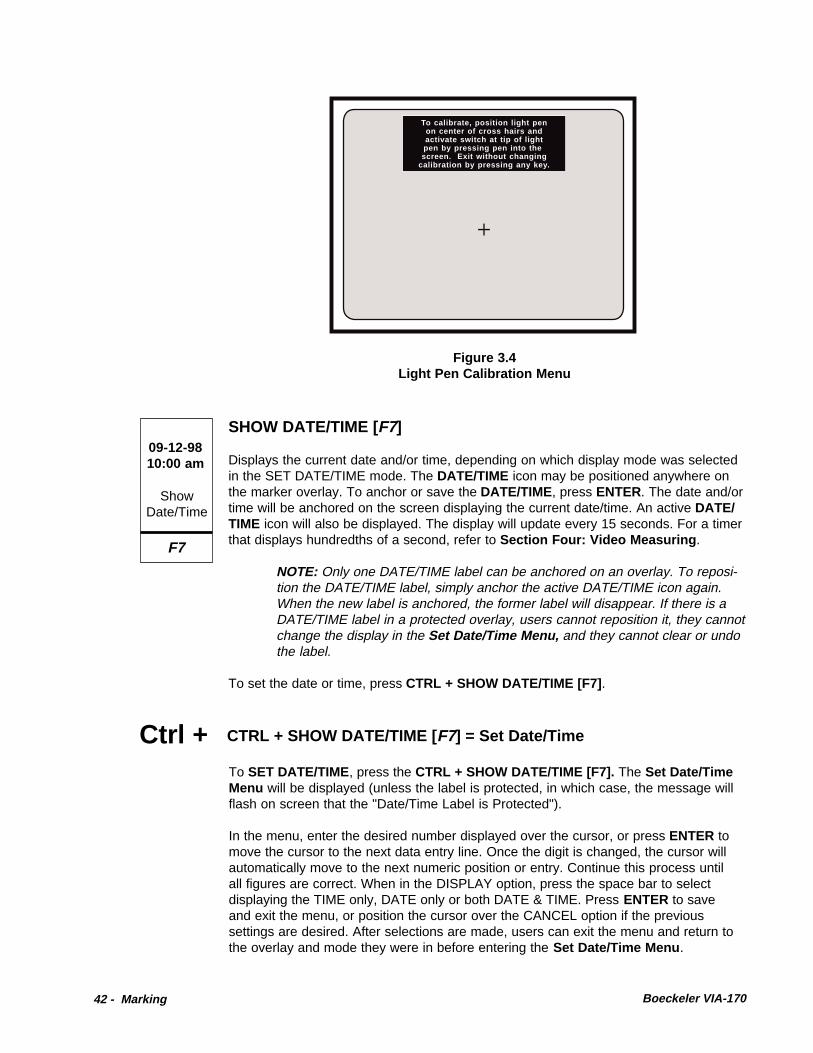
42 - Marking Boeckeler VIA-170
To calibrate, position light penon center of cross hairs andactivate switch at tip of lightpen by pressing pen into thescreen. Exit without changing
calibration by pressing any key.
Figure 3.4Light Pen Calibration Menu
Displays the current date and/or time, depending on which display mode was selectedin the SET DATE/TIME mode. The DATE/TIME icon may be positioned anywhere onthe marker overlay. To anchor or save the DATE/TIME, press ENTER. The date and/ortime will be anchored on the screen displaying the current date/time. An active DATE/TIME icon will also be displayed. The display will update every 15 seconds. For a timerthat displays hundredths of a second, refer to Section Four: Video Measuring .
NOTE: Only one DATE/TIME label can be anchored on an overlay. To reposi-tion the DATE/TIME label, simply anchor the active DATE/TIME icon again.When the new label is anchored, the former label will disappear. If there is aDATE/TIME label in a protected overlay, users cannot reposition it, they cannotchange the display in the Set Date/Time Menu, and they cannot clear or undothe label.
To set the date or time, press CTRL + SHOW DATE/TIME [F7] .
SHOW DATE/TIME [F7]
F7
ShowDate/Time
09-12-9810:00 am
To SET DATE/TIME, press the CTRL + SHOW DATE/TIME [F7]. The Set Date/TimeMenu will be displayed (unless the label is protected, in which case, the message willflash on screen that the "Date/Time Label is Protected").
In the menu, enter the desired number displayed over the cursor, or press ENTER tomove the cursor to the next data entry line. Once the digit is changed, the cursor willautomatically move to the next numeric position or entry. Continue this process untilall figures are correct. When in the DISPLAY option, press the space bar to selectdisplaying the TIME only, DATE only or both DATE & TIME. Press ENTER to saveand exit the menu, or position the cursor over the CANCEL option if the previoussettings are desired. After selections are made, users can exit the menu and return tothe overlay and mode they were in before entering the Set Date/Time Menu .
CTRL + SHOW DATE/TIME [ F7] = Set Date/TimeCtrl +

Boeckeler VIA-170 Marking - 43
CHANGE COLOR [ F8]
ChangeColor
F8
Changes the color or gray level of the active marker for optimum contrast with the videoimage or to contrast the current marker with other markers on the overlay. Repeatedlypressing this key will cycle through the three different colors or gray levels that havebeen assigned by the user in the Set Color Menu (discussed below). When the activemarker displays the desired color, the marker can be positioned and anchored in thatcolor.
NOTE: If the color of the graphics does not change from black, the brightnesslevel is too low and must be increased before selecting the color. Brightness isincreased in the Set Color Palette Menu . Consult the installation section ofthis manual to identify video interfaces which can create color markers for RGBand Y/C systems.
An active text label and active date/time label will appear in one of 9 different colorcombinations, since the background for the text also changes. For text and date/timelabels, users can reverse the sequence of choices by pressing SHIFT + CHANGECOLOR [F8] .
NOTE: For RGB systems with sync on green (and no VIA-RGB interface),color selections will be in hues of green and pink).
NOTE: On some Y/C systems with a VIA-Y/C interface and certain cameras ormonitors, there can be a slight blurring of vertical lines. To solve this problem,users can change the color of the VIA-170 lines to white, gray or black.
CTRL + CHANGE COLOR [ F8] = Set Color & BrightnessCtrl +This key combination calls up two menus that assist users in 1) defining a three-colorpalette and, 2) designing menus using these three colors. By designing a palette andmenus, the VIA-170 markers and menus can be made to optimally contrast with thevideo image, thus reducing eye strain and increasing legibility.
The first menu displayed is the Set Color Palette Menu in which users choose threecolors they would like to use for markers, measuring lines, and menus (refer to Figure3.5). Colors available are red, green, blue, magenta, yellow, white and black. To selecta color, press the CHANGE COLOR [F8] key until the desired color is displayed. Allcolors available for markers, measurement lines, and menus will be based on theselections made in this menu. No two colors can be the same. For example, if Color#1 is black, colors sequenced through for #2 and #3 will skip over the black option. Ifblack is desired for Color #2, operators need to change Color #1 from black to anothercolor.
Additionally, each color may be displayed in a range of brightness levels. If, for ex-ample, the color red is selected for Color #1, it can be displayed in one of five differentbrightness levels.
To select a brightness level for a color, press the SPACE BAR or BACKSPACE key tocycle through the brightness levels. When the desired brightness level is displayed,move on to define Color #2 by pressing the RIGHT POSITIONING key. Repeat theprocedure with Color #2 -- first select the color, then the brightness level, then move on

44 - Marking Boeckeler VIA-170
Figure 3.5Set Color Palette Menu
Set Color Palette
Press CHANGE COLOR [F8] tosequence through color options.Press SPACE BAR or BACKSPACE KEYto sequence through brightness levels.
Color #1
CANCEL SAVE
Color #2 Color #3
Figure 3.6Set Menu Colors Menu
SET MENU COLORS
Press SPACE BAR to sequencethrough options.
#1
CANCEL SAVEPREV MENU
#2 #3 #4
MENU TEXT COLOR: 3
MENU BACKGROUND COLOR: 1

Boeckeler VIA-170 Marking - 45
to Color #3 and repeat. When all three colors are set, select SAVE. Users will exit theSet Color Palette Menu and will be presented with the Set Menu Colors Menu (referto Figure 3.6).
The Set Menu Colors Menu will display the three selected colors plus a "no fill"option. Follow instructions to select MENU TEXT color and MENU BACKGROUNDcolor.
NOTE: The MENU TEXT option will not offer the "no fill" display, that is, textcannot be made to appear transparent. Also, the VIA-170 ensures that theMENU BACKGROUND color will be different than the text color by not offeringan already-used color option.
If the MENU BACKGROUND is #4 (no fill), all three colors will be available for menuTEXT.
When menu colors have been selected, select SAVE. Colors will be saved and userswill be returned to the marker overlay they were in before activating the color menus.
NOTE: Protected markers will reflect any changes made in the color palette.
TEXT/NUMBER KEYS
Pressing any of the 47 text/number keys will automatically activate the text mode. Text,in upper or lower case, will appear on screen wherever the last active marker or cursorwas located. After typing one line, the text label may be positioned anywhere on thescreen with keyboard POSITIONING keys or another controller. The text label may bepositioned before or after typing. To select a small or large size of text, press the SIZEOBJECTS/TEXT SIZE key combination before anchoring the line of text (CTRL +SHAPES [F3] ).
To anchor or save the active line of text, press ENTER. The line of text will beanchored and the text cursor will shift down one line, ready for another line of text. Textdoes not wrap, so press ENTER at each line end.
Pressing SHIFT + a TEXT/NUMBER key will display the upper case version of that key.
To exit the text mode, simply press any other marking or measuring function key.
NOTE: The numeric keypad on the far right of the keyboard can be activatedby pressing the NUM LOCK key.
When changing colors of an active text label, bear in mind that the text will cyclethrough the three available colors, and the text background will cycle through threeavailable colors. Never will the text color match the background color. In addition, thetext background will cycle to "no fill," so that text can be displayed without a back-ground. In total, there are nine different color combinations in which the backgroundand text can be displayed.

46 - Marking Boeckeler VIA-170
USING THE ACTION KEYS IN MARKING
UP/DOWN POSITIONING KEYS
Positions the active marker or cursor up or down one increment at a time, until themarker is anchored by pressing ENTERENTERENTERENTERENTER. For fine positioning, press CTRLCTRLCTRLCTRLCTRL + + + + + the UP UP UP UP UP orDOWNDOWNDOWNDOWNDOWN key. In ALIGN ModeALIGN ModeALIGN ModeALIGN ModeALIGN Mode, positions all markers in unison up or down.
POSITIONING keysPOSITIONING keysPOSITIONING keysPOSITIONING keysPOSITIONING keys are also used to size objects vertically. These objects includehorizontal grids, vertical scales, box grids, boxes and circles. Once in the sizing mode(CTRL + SHAPES [F3]CTRL + SHAPES [F3]CTRL + SHAPES [F3]CTRL + SHAPES [F3]CTRL + SHAPES [F3]), press the UPUPUPUPUP POSITIONING keyPOSITIONING keyPOSITIONING keyPOSITIONING keyPOSITIONING key to make the object taller.Press the DOWNDOWNDOWNDOWNDOWN POSITIONING keyPOSITIONING keyPOSITIONING keyPOSITIONING keyPOSITIONING key to make the object shorter. To save the size andexit sizing, press ENTERENTERENTERENTERENTER. The sized object may now be positioned anywhere on thescreen.
In menus, positions the cursor up or down among options, when such options areavailable. Moves page up or down in help messages.
LEFT/RIGHT POSITIONING KEYS
Positions the active marker or cursor left or right one increment at a time, until themarker is anchored by pressing ENTER. For fine positioning, press CTRL + the LEFTor RIGHT key. In ALIGN Mode , positions all markers in unison left or right.
This key is also used to size objects horizontally. These objects include vertical grids,horizontal scales, box grids, boxes and circles. Once in the sizing mode (CTRL +SHAPES [F3] ), press the LEFT POSITIONING key to make the shape wider. Pressthe RIGHT POSITIONING key to make the shape narrower. To save the size and exitsizing, press ENTER. The sized object may now be positioned anywhere on thescreen.
In menus, positions the cursor left or right among options, when such options areavailable.
ENTER STATISTIC [ Insert ]
Not used in Marking ModeMarking ModeMarking ModeMarking ModeMarking Mode.
OVERLAY [ Home]
Removes the cursor, active markers and data lines (marker size/coordinates; timer)from the screen so that only the anchored markers in the current overlay are visible.This option is usually desired before making a video copy.
To regain an active marker or cursor on the overlay, press any function key.

Boeckeler VIA-170 Marking - 47
CTRL + OVERLAY [ Home] = Undelete
Restores recently deleted marker to its original location on the marker overlay. Ifmarkers were recently cleared, pressing CTRL + OVERLAY [Home] restores the fulloverlay of markers. In a protected marker overlay, the undelete command only affectsadded markers. Undelete does not affect protected markers.
Ctrl +
PREV OVERLAY [ Page Up]
Displays the previous overlay and the markers stored in that overlay (if any). Pressingthis key repeatedly will continue to display each previous overlay in descending order.The number of each new overlay will appear briefly at the bottom right corner of thescreen. Ten different overlays may be stored (#1 - #10).
If the overlay had been aligned, the aligned markers will be displayed at their savedoffset, but the ALIGN Mode will not be active. This means that the entire overlay willnot be positionable until users activate the ALIGN Mode .
UNDO [Delete]
Erases markers one at a time, beginning with the most recently anchored marker. Thiskey may be repeatedly pressed until all anchored graphics have been erased. TheUNDO key will not remove the active marker or cursor. To remove the active graphic orcursor, press OVERLAY [ Home]. If users mistakenly erase a marker, they may "unde-lete" it by pressing CTRL + OVERLAY [Home] .
In a protected marker overlay, the UNDO key only affects added markers. UNDO[Delete] does not affect protected markers. When all added markers have been erasedand only protected markers remain, attempting an UNDO will briefly display the mes-sage "Markers Protected," and users will returned to the protected overlay. To UNDOa protected marker, the password holder needs to enter the Security Menu , CTRL +POINTERS [F1] , select Marker Overlay Protect OFF , exit the menu, erase the desiredmarker(s), then enter the Security Menu and select Marker Overlay Protect ON .
CLEAR [ End]
Clears the overlay of all markers at once. A warning message will appear on screen toavoid an unintentional erase. To proceed with the clearing procedure, select theCLEAR option. To cancel the procedure and retain current markers, select CANCEL .After clearing, the active marker or cursor will remain on screen even when all graphicshave been cleared. To remove the active marker or cursor, press OVERLAY [ Home].To "undelete" cleared markers, press CTRL + OVERLAY [Home] .
In a protected marker overlay, the CLEAR key only affects added markers. CLEAR[End] does not affect protected markers. To CLEAR protected markers, the passwordholder needs to enter the Security Menu , CTRL + POINTERS [F1] , select MarkerOverlay Protect OFF , exit the menu, and clear the markers.

48 - Marking Boeckeler VIA-170
Ctrl +
NEXT OVERLAY [ Page Down ]
Advances users to the next overlay and any markers stored in that overlay. Pressingthis key repeatedly will continue to display the next overlay in ascending order. Thenumber of each new overlay will appear briefly at the bottom right corner of the screen.Ten different overlays may be stored (#1 - #10).
If the overlay was aligned, the aligned markers will be displayed at their saved offset,but the ALIGN Mode will not be active. This means that the entire overlay will not bepositionable until users activate the ALIGN Mode .
ENTER¿Anchors an active marker. Once dropped, a marker cannot be moved or changed.However, markers may be removed by pressing UNDO [Delete] or CLEAR [End] . In aprotected overlay, users can anchor additional markers over protected markers, butthey can erase and clear only the added markers.
In ALIGN Mode, anchors all markers in the current offset and exits ALIGN Mode .
In menus, saves option as displayed and advances user to next option or next action.
CTRL + CLEAR [ End] = Clear Offset Created in Align Mode
Clears the offset (alignment) of markers in the current overlay so that coordinates willreturn to their default position (X = 0, Y = 0). A warning message will appear on screento avoid an unintentional clear. Unaligned overlays will remain unchanged.
NOTE: Even when in a Measurement Mode , users will be able to clear anoffset with this key combination. Also, a protected marker overlay can becleared of its alignment.
Ctrl + CTRL + POINTERS [F1] = Security Menu
Displays the Security Menu if users enter the correct password. Once the password isentered, users may choose to turn ON or OFF the Marker Overlay Protect . Doubleframed options are active. To change the selected option, highlight the option desired
ALL GRAPHICS ON/OFF [ ESC]
Turns off the VIA-170 overlay (including menus) so that only the video image isdisplayed. Pressing this key again, or any other function key, will turn on the VIA-170overlay and display the markers as they were before pressing ALL GRAPHICS ON/OFF.
This key is different from the OVERLAY [Home] key which allows users to view boththe image and markers without the cursor or active marker.
Esc
AllGraphicsOn/Off

Boeckeler VIA-170 Marking - 49
and press ENTER. This new selection will become double framed and remain so untilchanged. To save the new selections, highlight SAVE and press ENTER. MarkerOverlay Protect ON ensures that current markers cannot be erased or cleared exceptwith a password. All users will be able to change between overlays (1-10). All users willbe able to anchor and save additional markers over the protected overlay. However,only the added markers can be erased or cleared from the overlay. Users can changethe color or alignment of the protected overlay. If password holders wish to add pro-tected markers to a protected overlay, they may add the markers, enter the SecurityMenu , and re-select Marker Overlay Protect ON , then SAVE. This will re-save theprotected overlay to include the added markers. Marker Overlay Protect OFF allowsall users to erase or clear all displayed markers. To change the password (or to enter apassword for the first time), select the CHANGE PASSWORD option. Another menuappears which allows the user to enter the new password, confirm it, then SAVE orCANCEL the change. NOTE: Selecting DELETE as the first character deletes thepassword entirely. Pressing ENTER after a character signifies this that the entry iscomplete (it is possible to have a password with less than eight characters). Oncesaved, this new password must be used in order to enter the Security Menu again toprotect new markers or "un-protect" markers so that they can be erased. NOTE: If apassword is not entered into the system, an overlay can still be protected. However,users will not need a password to enter the Security Menu . This method allows allusers to make purposeful changes to protected overlays, but avoids accidental era-sures or changes. For Calibration Protection, refer to page 65.
SelectCalibr. #
Scroll Lock
#SELECT CALIBRATION # [ Scroll Lock]
Calls up the Select Calibration Menu in which operators select which preset calibra-tion to use before sizing markers or before aligning markers in the ALIGN Mode . Userswill have a choice of 10 saved calibrations (#0 - #9). Units and labelling information foreach calibration number are also displayed in the menu to aid in quick selection.
If markers are being sized and users have selected to display marker size, the calibra-
Ctrl + CTRL + RS-232 TRANSMIT = Set RS-232
Displays the RS-232 Menu in which users set RS-232 parameters, including baudrate (300, 600, 1200, 2400, 4800, 9600) and a terminator carriage return (return only,or return plus line feed). The default settings are a baud rate of 9600 and a carriagereturn + line feed. After entering the choices, select ENTER to save the changes orselect CANCEL to exit without saving changes. Users will be returned to the overlayand mode they were in before setting print parameters. To program a computer toaccept the downloaded information, refer to Section Five: Communication .
RS-232 TRANSMIT [Print Screen ]
Transmits the active marker coordinates and/or active marker size, through an RS-232serial port to a computer or ASCII terminal. The coordinates and/or marker size mustbe displayed on screen in order to print. To select the desired display before printing,press the SHOW MARKER SIZE/COORDINATES key combination CTRL + SCALES/GRIDS [F2] and make a display selection. In ALIGN Mode , offset coordinates (inpixels) and offset units (in calibrated units) will be transmitted if they are displayed.
RS-232Transmit
Print Screen

50 - Marking Boeckeler VIA-170
tion number selected will affect the resulting measurements. Also, if users are in theALIGN Mode , the calibration number will affect the offset distance display at the top ofthe screen since this display utilizes calibrated units (the offset coordinates displayedat the lower left of the screen reflects coordinates in pixels).
Calls up a series of Calibration Menus which assist users in changing the calibrationof an overlay. First, select the desired overlay, then press the CTRL + SELECTCALIBRATION # [Scroll Lock] . Follow instructions to position measuring lines andenter XY values. Users are also given the opportunity to label the calibration with units,magnification, ID# or any other label information. NOTE: Always calibrate using astage micrometer or other object of known size, and recheck calibrations. For accurateline positioning and other calibration details, refer to Section 4: Video Measuring ,Calibration. Calibrations cannot be changed if they are protected (see page 66).
SELECT CALIBRATION # [Scroll Lock ] = CalibrateCtrl +
HELP [Pause/Break ]
Activates the HELP Mode. Pressing HELP [Pause/Break] , then any other key (or keycombination) will display information about the use of that key (or key combination).Arrows in the upper right corner of the HELP screen indicate than an additional pageof HELP is available. Press the UP or DOWN POSITIONING key to access that page.
To exit HELP, press ENTER.
?Help
Pause/Break
Activates a demonstration of the VIA-170 features which may be useful in giving newusers an overall orientation on the product. The demonstration is brief. To cancel thedemonstration while in progress, press any function key. To pause the demonstration,press the HELP [Pause/Break] key. To speed up certain portions of the demonstra-tion, repeatedly press [Scroll Lock] until the desired feature is displayed. The demon-stration will not fast forward while motion is displayed.
HELP [Pause/Break ] = Demonstration of FeaturesCtrl +
ALT + I = Autointercept On/OffAlt +Automatically closes the gap between endpoints of a drawn line when those endpointsare fairly close together. This feature is desired when users are preparing to measurethe area of an image, which must be defined with a closed shape or closed freehanddrawing. Turning on the autointercept feature enables users to draw a shape withoutconcern for making a complete closure. When the drawing is nearly closed, and thelight pen is lifted away from the screen, the VIA-170 will automatically draw a lineconnecting the two ends of the line, thus forming a shape. To turn off AUTOINTER-CEPT, press ALT + I again. After turning on or off AUTOINTERCEPT, a brief mes-sage will be displayed as to whether the feature has been turned on or off.

Boeckeler VIA-170 Measuring - 51
Section Four:Video Measuring

52 - Measuring Boeckeler VIA-170

Boeckeler VIA-170 Measuring - 53
OVERVIEW
It is important to understand some of the basic concepts about how the MeasurementMode of the VIA-170 works in order to calibrate and use video measuring effectively.
All measurements performed with the VIA-170 are scalar numbers which are indepen-dent of units. In other words, a measurement displayed as X = 1.000 could representone inch, one millimeter or one micron. The decimal point functions merely as a placeholder and has no mathematical significance. The unit of measure is determined by thedevice used for calibration.
To display a measurement, the VIA-170 performs several internal procedures. In simpleterms, the VIA-170 superimposes an invisible grid over the video image displayed onthe monitor. This grid, using NTSC standards, is 1024 elements wide (X direction) by482 elements high (Y direction). For PAL and CCIR standards, the grid is 1024 by 512.An individual element in the grid is called a pixel, which stands for picture element. Thevertical video measuring lines are four pixels wide, and the horizontal lines are twopixels wide. Any one of the four measuring lines may be moved one pixel at a time.When an operator positions the measuring lines against the edges of an object, theVIA-170 counts the number of pixels between the measuring lines. This number ismultiplied by an internally generated constant called a scale factor. The product isdisplayed as a measurement in the upper left-hand corner of the video screen. Eachmeasuring key's function is described in the next section, followed by step-by-stepinstructions for calibrating and measuring.

54 - Measuring Boeckeler VIA-170
THE MEASUREMENT MODE
DescriptionWhen operators press the XY MEASURE [F9] key, the ANGLES/CIRCLES [F10] key,the COUNT [F11] key or the AREA/CHORDS [F12] key, the VIA-170 displays one of10 different Measurement Modes, over the video image (refer to Figure 4.1). Eachmode includes the corresponding measuring lines or cursors and the measurementdata. The display of this data varies slightly depending upon the Measurement Modein use. A description of each of the nine measurement displays is given below.
The upper left of the screen:
X= continuously displays the distance between the vertical mea-suring lines when in the X Mode .
Y= continuously displays the distance between the horizontalmeasuring lines when in the Y Mode .
X= Y= continuously displays the distance between the vertical andhorizontal measuring lines when in the XY Mode .
D= continuously displays the distance between the cross hairscursors when in the P-P Mode.
A= displays the angle when defined by four points in the ANGLEMode.
R= C= displays the radius and circumference of a circle when definedby the three points in the CIRCLE Mode .
A= displays the area of a closed shape when in the AREA/CHORDS Mode .
D1= D2= displays the short and long chords for a shape when in theAREA/CHORDS Mode .
A(-J)= displays the number of cells or particles counted when in theCOUNT Mode . The count is displayed for the tag selected(A through J).
00:00:00.00 displays the elapsed time when in the TIMER Mode (either theTimer w/ XY Measurement Mode , CTRL + [F10] ; or Timer w/Markers Mode , CTRL + [F12] ).
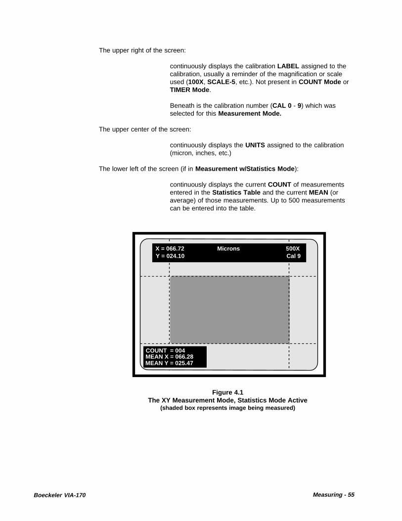
Boeckeler VIA-170 Measuring - 55
The upper right of the screen:
continuously displays the calibration LABEL assigned to thecalibration, usually a reminder of the magnification or scaleused (100X, SCALE-5 , etc.). Not present in COUNT Mode orTIMER Mode .
Beneath is the calibration number (CAL 0 - 9) which wasselected for this Measurement Mode.
The upper center of the screen:
continuously displays the UNITS assigned to the calibration(micron, inches, etc.)
The lower left of the screen (if in Measurement w/Statistics Mode ):
continuously displays the current COUNT of measurementsentered in the Statistics Table and the current MEAN (oraverage) of those measurements. Up to 500 measurementscan be entered into the table.
Figure 4.1The XY Measurement Mode, Statistics Mode Active
(shaded box represents image being measured)
X = 066.72 Microns 500XY = 024.10 Cal 9
COUNT = 004MEAN X = 066.28MEAN Y = 025.47

56 - Measuring Boeckeler VIA-170
USING THE MEASUREMENT KEYS
Highlighted in Figure 4.2 are the VIA-170 keyboard function keys used while in theMeasurement Mode . These measurement keys include keys which select one of tendifferent Measurement Modes , set up ten different measurement calibrations, andselect the line pattern of measuring lines.
The Measurement Mode is entered anytime the XY MEASURE [F9], ANGLES/CIRCLES [F10] , COUNT [F11] or AREA/CHORDS [F12] keys are pressed, or if atimer is activated (CTRL + [F11] or [F12] ). If users are in the Marker Mode , pressingany of the four measurement keys will automatically exit marking and enter measuring.Only the anchored markers in the current overlay will be displayed on screen alongwith the selected measuring lines or cursors. Calibration and measuring of the videoimage can now take place.
Serving users in both the Measurement Mode and the Marker Mode are the actionkeys (refer to Figure 4.2). In the Measurement Mode , these keys perform actions withregard to the calibration and positioning of the measurement lines and cursors. Actionkeys also move users through the ten stored marker overlays or assist in selecting oneof ten calibration numbers. Action keys also erase an anchored marker without exitingthe Measurement Mode . Users may also select to view the object being measured,with or without the measuring lines, at the touch of an action key.
A general measuring procedure is given on the next page, followed by a description ofeach measurement key function. Step-by-step procedures in calibrating and measuringa video image follow these function key descriptions.
Figure 4.2VIA-170 Keyboard Controller
MARKER KEYS(Graphics)
ACTION KEYS
MARKER KEYS(Text/Numbers)
MEASUREMENT KEYS

Boeckeler VIA-170 Measuring - 57
General Measuring ProceduresThe following is a general procedure for measuring. Specific procedures for calibratingand for measuring in each Measurement Mode are discussed in the following pages.
To measure an object in the field of view:
1. Calibrate the VIA-170 and check the calibration by measuring an object ofknown size before critical measurements are begun. Refer to the calibrationprocedures beginning on page 70.
NOTE: Operators will assign the calibration to one of ten different calibrationnumbers (CAL#0-9 ) which are stored in the VIA-170. Each CAL# will beaccompanied by labels to remind users of units used, magnification, etc.
2. Measure the object in the field of view .
A. Select the desired marker overlay by pressing the PREV OVERLAY [PageUp] key or NEXT OVERLAY [Page Down]. The measuring lines or cursorswill remain on screen with the selected marker overlay.
B. Press the XY MEASURE [F9] key, ANGLES/CIRCLES [F10] key, COUNT[F11] key or the AREA CHORDS [F8] key. Press the key until the desiredMeasurement Mode is displayed on screen. If measurements are to beentered into the Statistics Table , press Measure w/ Statistics ALT+ [F9].
C. Select the desired line pattern by pressing the CTRL + XY MEASURE[F9] for solid or dashed lines in X, Y or XY Modes . Selection is notapplicable to other Measurement Modes .
D. Press the SELECT CALIBRATION # [Scroll Lock] key and select CAL# .
E. Properly position the measuring lines or measuring cursors to mea-sure the object in the field of view . Refer to the section on positioningthe lines, if needed, beginning on page 75.
NOTE: To obtain an AREA , operators anchor or draw a closed shape aroundthe object being measured, then press AREA/CHORDS [F12] to measure.
3. Note the displayed measurement reading in the upper left of the screen.
NOTE: To time an event while measuring, press CTRL + TIMER W/ XYMEASUREMENT [F11] . Time is displayed in the lower right of the screen.
4. Store or transmit measurement, or enter measurement in Statistics Table.
A. To transmit via the RS-232 serial port for ASCII terminal or computer,press the RS-232 TRANSMIT [Print Screen] key .
B. To enter measurement into Statistics Table , be sure you are in Measurew/ Statistics Mode (ALT + [F9] ), then press ENTER STATISTIC [Insert] .
5. To exit measuring or begin marking, press any marker key .

58 - Measuring Boeckeler VIA-170
XY MEASURE [F9]
F9
XYMeasure
Measurement Keys
Activates one of four different modes in which an operator may perform a dimensionalmeasurement. Each time this key is pressed, users will cycle to the next MeasurementMode : X, Y, XY and P-P (point-to-point). To cycle backwards through the options pressthe SHIFT + XY MEASURE [F9] .
A brief description of each Measurement Mode is given below.
X the distance between two vertical lines is continuously displayed.
Y the distance between two horizontal lines is continuously displayed.
XY the distance between two vertical lines and the distance between twohorizontal lines are continuously displayed.
P-P the distance between two points is continuously displayed.
To measure XY dimensions in the Measure w/ Statistics Mode , select MeasurementMode desired, then press MEASURE W/STATS, ALT + XY Measure [F9] . The Statis-tics Display will appear on screen along with the measurement lines or cursors.
Detailed XY Measurement procedures begin on page 79.
Ctrl + CTRL + XY MEASURE [ F9] = Change Line Pattern
Pressing the CTRL key together with the XY MEASURE [F9] will change the pattern ofmeasuring lines from solid to dashed, or from dashed to solid. This feature is designedas a visual aid so that operators can more easily differentiate measuring lines from thecamera image or from the markers.
NOTE: The pattern selection only affects measuring lines in the X, Y or XYModes .
ALT + ALT + XY MEASURE [ F9] = Measure w/ Statistics
After entering the desired Measurement Mode (XY MEASURE, ANGLES/CIRCLES ,or AREA/CHORDS ), users can choose to measure while displaying the average oftheir measurements. This requires being in the Measure w/Statistics Mode , becausemeasurement procedures will include creating and maintaining a separately displayedStatistics Table . Pressing the ALT key together with the XY MEASURE [F9] willchange the displayed Measurement Mode to a Measure w/ Statistics Mode . AStatistics Display will appear on screen in the lower left corner, along with the mea-suring lines or cursors (refer to Figure 4.1, page 55). The additional display shows thecurrent COUNT of values that have been entered into the Statistics Table and thecurrent MEAN. "UNDEF" means there aren't enough measurements in the table towarrant a calculation. "INVALID" means that measurements in the Statistics Table are

Boeckeler VIA-170 Measuring - 59
different than those displayed in the Measurement w/Statistics Mode (e.g., the user isin the XY Measure w/ Statistics Mode and the table contains angle measurements).
After measuring, to enter the displayed measurement(s) into the Statistics Table ,press the ENTER STATISTIC [Insert] key. The Statistics Display will now read oneCOUNT higher and the MEAN will incorporate the new value. To view the entireStatistics Table or to edit it, press STATISTICS TABLE, ALT + S .
ANGLES/CIRCLES [ F10]
Activates one of two different modes in which an operator may perform either a mea-surement of an angle or a measurement of a circle. A brief description of the twomeasurement modes is given below.
ANGLE displays the angle when defined by at least four points (or at least twopoints per line segment).
CIRCLE displays the radius and circumference of a circle when defined byat least three points.
To measure angles or circles in the Measure w/Statistics Mode , enter the ANGLE orCIRCLE Measurement Mode , then press ALT + XY Measure [F9] . The StatisticsDisplay will appear on screen along with the measurement cursors.
Detailed ANGLE/CIRCLE Measurement procedures begin on page 89.
F10
Angles,Circles
xx
xxx
CTRL + ANGLES / CIRCLES [ F10] = Clear Points
Clears points from a circle or angle measurement. An active cursor will remain, readyto begin a new circle or angle. If in the Measurement w/Statistics Mode , be sure toinsert the displayed measurement in the Statistics Table before clearing points.
COUNT [F11]
F11
1, 2, 3,
Count
Activates the cell/particle counting mode. Each time this key is pressed, users will cyclethrough to the next tag option (A-J). To cycle backwards through the options press theSHIFT + COUNT [F11] . A brief description of the display options is given below.
A displays the total number of cells/particles counted using the A tag.
B displays the total number of cells/particles counted using the B tag.
C displays the total number of cells/particles counted using the C tag.
D displays the total number of cells/particles counted using the D tag.
etc.,through J displays the total number of cells/particles counted using the J tag.
Ctrl +

60 - Measuring Boeckeler VIA-170
Detailed COUNT Measurement procedures begin on page 98. NOTE: The Measure-ment w/Statistics Mode is not active in COUNT Mode. Also, unlike markers, when tagsare cleared, pressing UNDELETE, CTRL + Overlay [Home] will not retrieve clearedtags. Undelete will only undelete the most recently anchored tag.
Ctrl + CTRL + COUNT [F11] = Timer w / XY Measurement
Displays timer while users are in the XY Measurement Mode . Users can move mea-surement lines and drop cursors while the timer is running. A brief description of thismode is given below.
00:00:00.0 the elapsed time is continuously displayed from the moment thetimer is activated to the moment it is stopped.
Detailed TIMER w/ XY Measurement procedures begin on page 107. NOTE: TheMeasurement w/Statistics Mode is not active in TIMER Mode.
F12
AREA,CHORDS
AREA/CHORDS [ F12]
Activates one of three different options in which an operator may perform area andchord measurement. Each time this key is presesed, users will cycle through to thenext area or chord option. To cycle backwards, press SHIFT + AREA/CHORDS [F12] .A brief description of each option is given below.
A the area within any closed shape (drawing or marker).
D1 the first distance defined by placing two end points.D2 the second distance defined by placing two end points.
When the desired option is selected, a preference arrow will appear immediately rightof the selected measurement display.
To measure areas or chords in the Measure w/ Statistics Mode , enter the AREA/CHORDS Measurement Mode , select the desired option (A, D1 or D2), then pressMEASURE W/ STATISTICS, ALT + XY Measure [F9] . The Statistics Display willappear on screen along with the measurement cursors.
Detailed AREA/CHORDS Measurement procedures begin on page 98.
CTRL + AREA/CHORDS [ F12] = Timer w/ Markers
Displays timer while users are in the Marker Mode . Users cannot change a markeroverlay while the timer is running. A brief description of this mode is given below.
00:00:00.0 the elapsed time is continuously displayed from the moment thetimer is activated to the moment it is stopped.
Detailed TIMER w/ MARKERS procedures begin on page 105. NOTE: The Measure-ment w/Statistics Mode is not active in TIMER Mode.
Ctrl +
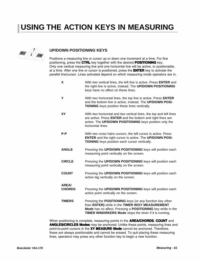
Boeckeler VIA-170 Measuring - 61
USING THE ACTION KEYS IN MEASURING
UP/DOWN POSITIONING KEYS
Positions a measuring line or cursor up or down one increment at a time. For finepositioning, press the CTRLCTRLCTRLCTRLCTRL key together with the desired POSITIONING POSITIONING POSITIONING POSITIONING POSITIONING key.Only one vertical measuring line and one horizontal line will be active, or positionable,at a time. After one line or cursor is positioned, press the ENTERENTERENTERENTERENTER key to activate theparallel line/cursor. Lines activated depend on which measuring mode operators are in.
X With two vertical lines, the left line is active. Press ENTER andthe right line is active, instead. The UP/DOWN POSITIONINGkeys have no affect on these lines.
Y With two horizontal lines, the top line is active. Press ENTERand the bottom line is active, instead. The UP/DOWN POSI-TIONING keys position these lines vertically.
XY With two horizontal and two vertical lines, the top and left linesare active. Press ENTER and the bottom and right lines areactive. The UP/DOWN POSITIONING keys position only thehorizontal lines.
P-P With two cross hairs cursors, the left cursor is active. PressENTER and the right cursor is active. The UP/DOWN POSI-TIONING keys position each cursor vertically.
ANGLE Pressing the UP/DOWN POSITIONING keys will position eachmeasuring point vertically on the screen.
CIRCLE Pressing the UP/DOWN POSITIONING keys will position eachmeasuring point vertically on the screen.
COUNT Pressing the UP/DOWN POSITIONING keys will position eachactive tag vertically on the screen.
AREA/CHORDS Pressing the UP/DOWN POSITIONING keys will position each
active point vertically on the screen.
TIMERS Pressing the POSITIONING keys (or any function key otherthan ENTER) while in the TIMER W/XY MEASUREMENTMode has no affect. Pressing a POSITIONING key while in theTIMER W/MARKERS Mode stops the timer if it is running.
When positioning is complete, measuring points in the AREA/CHORDSAREA/CHORDSAREA/CHORDSAREA/CHORDSAREA/CHORDS, COUNT COUNT COUNT COUNT COUNT andANGLES/CIRCLESANGLES/CIRCLESANGLES/CIRCLESANGLES/CIRCLESANGLES/CIRCLES ModesModesModesModesModes may be anchored. Unlike these points, measuring lines andpoint-to-point cursors in the XYXYXYXYXY MEASURE Mode MEASURE Mode MEASURE Mode MEASURE Mode MEASURE Mode cannot be anchored. Therefore,these are always positionable and cannot be erased. To quit placing these measuringlines, operators may press any other function key to begin a new function.

62 - Measuring Boeckeler VIA-170
Positions a measuring line or cursor left or right one increment at a time. For finepositioning, press the CTRLCTRLCTRLCTRLCTRL key together with the desired POSITIONINGPOSITIONINGPOSITIONINGPOSITIONINGPOSITIONING key.Only one vertical measuring line and one horizontal line will be active, or positionable,at a time. After one line/cursor is positioned, press the ENTERENTERENTERENTERENTER key to activate theparallel line/cursor. Lines activated depend on which measuring mode operators are in.
X With two vertical lines, the left line is active. Press ENTER andthe right line is active, instead. The LEFT/RIGHT POSITION-ING keys position these lines horizontally.
Y With two horizontal lines, the top line is active. Press ENTERand the bottom line is active, instead. LEFT/RIGHT POSITION-ING keys have no affect on these lines.
XY With two horizontal and two vertical lines, the top and left linesare active. Press ENTER and the bottom and right lines areactive. LEFT/RIGHT POSITIONING keys move only thevertical lines.
P-P With two cross hairs cursors, the left cursor is active. PressENTER and the right cursor is active. LEFT/RIGHT POSITION-ING keys move each cursor horizontally.
ANGLE Pressing the LEFT/RIGHT POSITIONING keys move eachactive cursor horizontally on the screen.
CIRCLE Pressing the LEFT/RIGHT POSITIONING keys move eachactive cursor horizontally on the screen.
COUNT Pressing the LEFT/RIGHT POSITIONING keys move eachactive cursor horizontally on the screen.
AREA/CHORDS Pressing the LEFT/RIGHT POSITIONING keys move each
active cursor horizontally on the screen.
TIMERS Pressing the POSITIONING keys (or any function key otherthan ENTER) while in the TIMER W/ XY MEASUREMENTMode has no affect. Pressing a POSITIONING key while in theTIMER W/MARKERS Mode stops the timer if it is running.
When positioning is complete, measuring points in the AREA/CHORDSAREA/CHORDSAREA/CHORDSAREA/CHORDSAREA/CHORDS, COUNT COUNT COUNT COUNT COUNT andANGLES/CIRCLESANGLES/CIRCLESANGLES/CIRCLESANGLES/CIRCLESANGLES/CIRCLES ModesModesModesModesModes may be anchored. Unlike these points, measuring lines andpoint-to-point cursors in the XYXYXYXYXY MEASURE Mode MEASURE Mode MEASURE Mode MEASURE Mode MEASURE Mode cannot be anchored. Therefore,these are always positionable and cannot be erased. To quit placing these measuringlines, operators may press any other function key to begin a new function.
LEFT/RIGHT POSITIONING KEYS

Boeckeler VIA-170 Measuring - 63
ENTER STATISTIC [ Insert ]
While in a Measure w/ Statistics Mode Measure w/ Statistics Mode Measure w/ Statistics Mode Measure w/ Statistics Mode Measure w/ Statistics Mode, enters the displayed measurement into theStatistics Table.Statistics Table.Statistics Table.Statistics Table.Statistics Table. In the Statistics TableStatistics TableStatistics TableStatistics TableStatistics Table, undeletes a deleted statistic. NOTE:NOTE:NOTE:NOTE:NOTE: Userswill be able to enter measurements that were made using different calibrations. Be surethat measurements entered are compatible with those already in the table.
In menus, does not affect cursor. Use ENTER ENTER ENTER ENTER ENTER key to select option.
OVERLAY [ Home]
Removes the measurement overlay from the screen so that only the anchored mark-ers in the current overlay are visible. This option may be desired before making avideo copy. To regain a measurement overlay, press the desired measurement key.
CTRL + OVERLAY [ Home] = UndeleteCtrl +Restores recently deleted marker to its original location on the overlay, even while thein a Measurement Mode . If markers were recently cleared, pressing Undelete, CTRL+ OVERLAY [Home] , restores the full overlay of markers. In a protected overlay,Undelete only affects added markers. Undelete does not affect protected markers.
PREV OVERLAY [ Page Up]
Displays the previous overlay and any markers stored in that overlay, along with thecurrent measuring lines or cursors (measuring points in ANGLES/CIRCLES Mode willbe erased). Pressing this key repeatedly will continue to display each previous overlayin descending order, along with the current measuring lines. The number of each newoverlay will appear briefly at the bottom right corner of the screen (#1-#10).
These overlays cannot take on new markers while in the current Measurement Mode .However, markers may be erased in the Measurement Mode (refer to the UNDO andCLEAR functions descriptions which follow). To create new markers in an overlay,press any marker function key. The measurement lines will disappear and markingfunctions will begin. After marking, press the desired Measurement Mode key to recallthe measuring lines or cursors last used.
UNDO [Delete]
Pressing UNDO [Delete] while in XY MEASURE Mode will erase anchored markersone at a time, beginning with the most recently anchored marker. The measurementoverlay will remain on screen during this process. In the COUNT Mode , pressing thiskey erases count tags (A, B, C, etc.) one at a time, beginning with the most recentlyanchored tag. Pressing this key in CIRCLES / ANGLES Mode or AREA/CHORDSMode will erase both a marker and all the measuring points. In a protected markeroverlay, UNDO only affects added markers. UNDO does not affect protected markers(refer to page 47). In the Statistics Table , deletes a statistic from the table.

64 - Measuring Boeckeler VIA-170
CLEAR [ End]
In the XY Measurement Modes , pressing this key will clear all the markers at once,but not the measuring lines or cursors. A warning message will appear on screen toavoid an unintentional erase. Press ENTER to confirm a full erase or press any key toexit the procedure without erasure. Measuring lines and measurement displays willremain on screen during this process. Protected markers will not be cleared.
In the ANGLES/CIRCLES Mode and AREA/CHORDS Mode , pressing CLEAR [End]will not only clear the screen of all markers, but will also clear the measurement cursorsso that operators may quickly begin a new calculation. Protected markers will not becleared.
In the COUNT Mode , pressing CLEAR [End] gives users the option to clear all thetags and set all counts to zero, or to clear only the tags while retaining the currentcounts. A warning message will appear on screen to avoid an unintentional erase.
To undelete a screen of recently cleared markers in all Measurement Modes exceptCOUNT, press CTRL + OVERLAY [Home] . In COUNT, this key combination undeletesthe most recently erased tag only.
CTRL + CLEAR [End] = Clear Offset Created in Align ModeCtrl +Clears the offset (alignment) of markers in the current overlay even while users are ina Measurement Mode . A warning message will appear on screen to avoid an uninten-tional clear. Offset coordinates will return to the default position (X=0, Y=0).
A protected overlay can be cleared of its alignment. Protection ensures that certainmarkers cannot be erased or cleared.
NEXT OVERLAY [ Page Down ]
Advances users to the next overlay and any markers stored in that overlay, along withthe current measuring lines or cursors (measuring points in ANGLES/CIRCLES Modewill be erased). Pressing this key repeatedly will continue to display the next overlay inascending order, along with the current measuring lines. The number of each newoverlay will appear briefly at the bottom right corner of the screen.
These overlays cannot take on new markers while in the current Measurement Mode .However, markers may be erased in the Measurement Mode (refer to the UNDO andCLEAR functions above). To create new markers in an overlay, press any markerfunction key. The measurement lines will disappear and marking functions will begin.After marking, press the desired Measurement key to recall measuring lines last used.
In measuring, activates a measuring line or cursor for positioning. Pressing it againactivates the parallel line or second cursor. In COUNT Mode , anchors a tag.
ENTER¿

Boeckeler VIA-170 Measuring - 65
In CIRCLES/ANGLES Mode , anchors a point. In menus, saves option as displayedand advances user to next option or next action.
CTRL + POINTERS [F1] = Security MenuCtrl +Displays the Security Menu if user enters the correct password. If there is no pass-word, user will advance to Security Menu . Once in the Security Menu , user maychoose to turn ON or OFF the Calibration Protect feature. Double framed options areactive. To change the selected option, highlight the option desired and press ENTER.This new selection will become double framed and remain so until changed. To saveselections, highlight SAVE and press ENTER. Calibration Protect ON ensures thatcalibrations cannot be altered except with a password. All users will be able to changebetween calibration #'s (0-9). Calibration Protect OFF makes all calibrations suscep-tible to being changed.
To change the password (or to enter a password for the first time), select the CHANGEPASSWORD option. A second menu appears which allows the user to enter the newpassword, confirm it, then SAVE or CANCEL the new password. NOTE: SelectingDELETE as the first character deletes the password entirely. Pressing ENTER after acharacter signifies that the entry is complete (it is possible to have a password with lessthan eight characters). Once saved, this password must be used in order to be able tochange protected calibrations, or to enter the Security Menu. NOTE: If a password isnot entered into the system (e.g., deleted), calibrations can still be protected. However,users will not need a password to enter the Security Menu . This method allows pur-poseful changes to protected calibrations, but not accidental changes. For instructionson Marker Overlay Protect, refer to page 49.
RS-232Transmit
PrintScreen
Turns off the VIA-170 marker overlay, measurement overlay, or menu so that only thevideo image is displayed.
Pressing this key again, or any other key, will turn on the VIA-170 overlay and displaythe measuring lines, data and markers as they were before pressing ALL GRAPHICSON/OFF [Esc] .
Different from the OVERLAY [Home] key which allows users to view both the imageand the anchored markers. Measuring lines, cursors and active markers will not bedisplayed.
ALL GRAPHICS ON/OFF [ ESC]
Esc
AllGraphicsOn/Off
RS-232 TRANSMIT [Print Screen ]
Pressing this key transmits the displayed measurements through an RS-232 serial portto a computer or ASCII terminal. The measurements must be displayed on screen inorder to print, so operators must be in a Measurement Mode . The results of eachmeasurement may be transmitted whether in the XY MEASURE, ANGLES/CIRCLES,COUNT, AREA/CHORDS or either of the TIMER Modes .
If in a Measure w/Statistics Mode , the Statistics Summary (current mean, standard

66 - Measuring Boeckeler VIA-170
deviation, low value, high value, and range) is transmitted, along with the displayedmeasurement. In the RS-232 Setup Menu, users have the option to transmit thesummary only or the summary plus all of the entered statistics.
Ctrl + CTRL + RS-232 TRANSMIT = Set RS-232 Parameters
Displays the RS-232 Menu in which users set RS-232 parameters, including baud rate(300, 600, 1200, 2400, 4800, 9600), terminator carriage return (return only, or returnplus line feed), and how to send statistics (summary only or summary with all statistics).The factory settings are a baud rate of 9600, a carriage return + line feed, and sendingthe summary of statistics only.
After entering the choices, select ENTER to save the changes or select CANCEL toexit without saving changes. To program a computer to accept the downloaded infor-mation, refer to Section Five: Communication .
SELECT CALIBRATION # [ Scroll Lock ]
Calls up the Select Calibration Menu in which operators select which preset calibra-tion to use before measuring. Users will have a choice of 10 saved calibrations (#0 -#9). Units and labelling information for each calibration number are also displayed inthe menu to aid in quick selection.
A CAL# may be selected before entering a Measurement Mode or while in a Mea-surement Mode (or Measurement w/Statistics Mode ). In any case, the CAL# shouldbe selected before measuring takes place since the measurement results are depen-dent upon the calibration used.
Some operators will use more than one CAL# on a single measurement. For example,users may have calibrated CAL#8 in inches and CAL#9 in metric units (millimeters,microns, etc.), thus two calibrations may be used as a means to convert a singlemeasurement into other units of measure. While the measurement display is in theupper left of the screen, the CAL # is shown in the upper right of the screen along withany label information that was entered during calibration.
If in the Measure w/Statistics Mode , users may change the CAL# as above, and entervalues into the Statistics Table using the new CAL# . WARNING: Users will be able toenter measurements that were made using different calibrations. Be sure that mea-surements entered are compatible with those already in the table. A warning messagewill only appear if values being entered into the table are from a different Measure-ment Mode than those already in the table (e.g., XY measurements -vs- angle mea-surements). The warning message will offer users the opportunity to clear the table ofcurrent values and enter the new value, or to proceed measuring without entering newvalues in the table.
#Select
Calibr. #
Scroll Lock
Calls up a series of Calibration Menus which assist users in changing the calibrationof an overlay. If calibrations are protected, a message will appear briefly on screen
SELECT CALIBRATION # [Scroll Lock ] = CalibrateCtrl +

Boeckeler VIA-170 Measuring - 67
reminding users "Calibrations are protected." To change a calibration, the passwordholder will need to enter the Security Menu , turn Calibration Protect OFF , SAVE thisselection, then exit the menu. If there is no password, any user can enter the SecurityMenu to make this selection. Now calibrations can be changed.
Once in the Calibration menu , select the desired marker overlay, then press the CTRLkey together with the SELECT CALIBRATION # [Scroll Lock] key. Follow instructionsto position measuring lines and enter XY values. Users are also given the opportunityto label the calibration number with units, magnification, ID# or any other label informa-tion. NOTE: Always calibrate using a stage micrometer or other object of known size,and recheck calibrations. For accurate line positioning and other calibration details,refer to Section 4: Video Measuring , Calibration.
After storing the new calibration, the VIA-170 will return operators to the measurementor marker overlay that displayed before entering the calibration mode. Detailed calibra-tion procedures begin on page 70.
?Help
HELP [Pause/Break ]
Activates the HELP Mode. Pressing HELP [Pause/Break] then any other key (or keycombination) will display information about the use of that key. Arrows in the upperright corner of the HELP screen indicate than an additional page of HELP is available.Press the UP or DOWN POSITIONING key to access that page. To exit HELP, pressENTER. If users are in a menu, they should exit the menu before accessing HELP.
Pause/Break
HELP [Pause/Break] = Demonstration of Features
Activates a demonstration of the VIA-170 features which may be useful in giving newusers an overall orientation on the product. The demonstration is brief. To cancel thedemonstration while in progress, press any function key. To pause the demonstration,press the HELP [Pause/Break] key. To speed up certain portions of the demonstra-tion, repeatedly press SELECT CALIBR. # [Scroll Lock] until the desired feature isdisplayed. The demonstration will not fast forward while the screen is displayingmotion.
Ctrl +
TEXT/NUMBER KEYS
In the Select Calibration Menu , numbers 0 through 9 may be typed in the NEWCALIBRATION # option box.
NOTE: The numeric keypad on the far right of the keyboard can be activatedby pressing the NUM LOCK key.
In the second Calibration Menu , users may type alphanumeric characters to label thecalibration # with units and any other calibration information.
In ANGLES Mode , pressing the SPACE BAR ends the definition of the first leg of an

68 - Measuring Boeckeler VIA-170
angle, so that users can begin defining the second leg (and vice versa).
In some menus, repeatedly pressing the SPACE BAR cycles through the availableoptions. The option displayed can then be selected by pressing ENTER.
Alt + ALT + A = Show/Hide Angle While Measuring Angles
Toggles on and off the VIA-170 angle display shown while users define an angle.Turning on the angle display can help users align each leg of the angle against theobject in the field of view. Turning off the display may be preferred when users need anunobstructed view of the video image being measured.
NOTE: If users have placed the first leg of the angle and are defining thesecond leg of the angle when they turn on or off the display, the new displaywill affect only the second leg.
ALT + C = Show/Hide Circle While Measuring Circles
Toggles on and off the VIA-170 circle display shown while users define a circle. Turn-ing on the circle display can help users visualize the circle or arc being measured.Turning off the display may be preferred when users need an unobstructed view of thevideo image being measured.
NOTE: If users have placed the first leg of the angle and are defining thesecond leg of the angle when they turn on or off the display, the new displaywill affect only the second leg.
Alt +
ALT + D = Clear Statistics Table
Clears the Statistics Table of all entered values. Users may clear the table from anymode, measuring or marking. A warning message will appear to avoid an unintentionalclear.
Alt +
ALT + S = Statistics Table
Displays the Statistics Table and all values (if any) that were entered while in aMeasure w/Statistics Mode . If the table is empty of entries, values will be displayed"UNDEF" for undefined. This table may be accessed from any mode, although it onlyreflects values entered from a Measure w/Statistics Mode .
The Statistics Summary (refer to Figure 4.3) is at the top of the table and displays theCOUNT or the total number of active values entered in the table. The MEAN is the sumof all the active values divided by the COUNT. ST DEV (Standard Deviation) is ameasure of the variability of the data. RANGE is the difference between the HI (high-est) and LO (lowest) active values. This area cannot be edited, although it can changeas values are added, deleted, undeleted or cleared from the table.
Alt +

Boeckeler VIA-170 Measuring - 69
To delete a value, highlight the value and press DELETE [Undo] . To undelete a value,highlight the value and press ENTER STATISTIC [Insert] . To clear all values, pressCLEAR STATISTICS TABLE, ALT + D .
Up to 500 values can be stored in the Statistics Table . To view the next page ofvalues, highlight the NEXT option and press ENTER. To view the previous page ofvalues, highlight the PREV option and press ENTER. To exit the Statistics Table ,highlight the EXIT option and press ENTER.
Statistics are transmitted by entering the desired Measure w/ Statistics Mode , thenpressing the RS-2323 TRANSMIT [Print Screen] key. To select whether all statisticsget printed or just the Statistics Summary , press CTRL + RS-232 [Print screen] .
WARNING: Users will be able to enter measurements that were made using differentcalibrations. Be sure that measurements entered are compatible with those already inthe table. A warning message will only appear if values being entered into the table arefrom a different Measurement Mode than those already in the table (e.g., XY measure-ments -vs- angle measurements). This warning message will offer users the opportu-nity to clear the table of current values and enter the new value or to proceed measur-ing without entering new values in the table.
Statistics Table
PREV EXIT
MEAN: 0041.2 0258.6 R C
ST DEV: 0000.4 0002.5LO: 0040.8 0256.0
NEXT
HI: 0041.6 0261.1RANGE: 0000.8 0005.1DEL #
001 0041.2 0258.7002 0041.6 0261.1003 0040.8 0256.0
007 UNDEF UNDEF
005 UNDEF UNDEF006 UNDEF UNDEF
005 UNDEF UNDEF
008 UNDEF UNDEF
Figure 4.3The Statistics Table
for Circle Measurement(Radius, Circumference)
Shift + SHIFT + Function Key = Reverse Toggle
Allows users to cycle backwards through the available choices. Measurement functionskeys with which SHIFT can be used include XY MEASURE [F9] and COUNT [F11] .

70 - Measuring Boeckeler VIA-170
CALIBRATIONThe basic concept behind calibration is simple. The operator places an object of knownsize in the field of view of the camera, positions measuring lines against its edges, andenters the object’s dimensions on the screen. The VIA-170 then calculates a scalefactor, and calibration is complete. Although the calibration process is easy, subsequentmeasurement errors may occur if an operator does not adhere to the calibration proce-dures which follow.
As discussed in the Overview on page 53, the video measuring lines move within a gridwhich is, for NTSC standards, 1024 pixels wide by 482 pixels high (or, for CCIR andPAL standards, 1024 pixels wide by 512 pixels high). In other words, a vertical measur-ing line may be positioned in any one of 1024 locations from left to right on the screen.Similarly, a horizontal line has 482 potential locations from top to bottom.
The VIA-170 maintains a continuous count of the number of pixels between the mea-suring lines. Measurements are internally calculated by multiplying the number of pixelscounted between the lines by a scale factor. The scale factor is equal to the amount themeasurement value changes when one measuring line is moved one pixel. For ex-ample, if the screen initially displayed X = 0.2000 and then displayed X = 0.2005 afterone measuring line was moved one pixel, then the scale factor would be five (5). Thus,in this example every time a measuring line is moved one pixel, the measurement willchange by an increment of five.
During calibration, operators position the measuring lines and then manually enter thevalues for the X and Y axes. The VIA-170 divides the value for each axis by the numberof pixels between the measuring lines. The result is then stored as the new scale factor.For example, if an operator entered the value X = 4.0000 and the VIA-170 counted 400pixels between the measuring lines, then the resulting scale factor would be 100. If theoperator then moved the lines apart by one more pixel, the measurement would read X= 4.0100. The decimal point is positioned by the operator and has no mathematicalsignificance.
The internally calculated scale factor discussed above should not be confused with thecalibration number (CAL# ) which is a label displayed in the upper right-hand corner ofthe measurement screen. This label allows the operator to assign a different number toeach calibration. A maximum of ten different calibration numbers may be stored. Alsodisplayed in the upper right corner is the calibration label. Typically, calibration labelsserve as reminders of the power of magnification (if any) used during calibration.Calibration numbers and calibration labels do not affect measurement calculations inany way.
The calibration of the VIA-170 is valid only for a particular measurement situation.Recalibration is required if the focal distance or any other parameter is changed. Ifoperators are using the VIA-170 in a permanent installation where the field of view isfixed, then the set up and calibration numbers stored in the unit may be used again andagain without recalibration.

Boeckeler VIA-170 Measuring - 71
General Calibration Procedures
Calibration for all Measurement Modes can be completed most efficiently in XYMeasurement Mode . It is for this reason that the VIA-170 is programmed to help userscalibrate using both horizontal and vertical measurements. Since many VIA-170applications include a video system attached to a microscope, the calibration proce-dure described herein utilizes a stage micrometer. Calibration may be performed,however, by placing any object of known size within the field of view of the camera.The particular object used for calibration should be chosen with attention to the specificapplication for which the VIA-170 is being used.
To calibrate the VIA-170:
1. Place a stage micrometer (or another object of known size) in the field of view ofthe camera.
2. On the VIA-170 keyboard controller, press the CTRL + SELECT CALIBRATION #[Scroll Lock] key combination .
The First Calibration Menu will appear along with the image of the stagemicrometer. The menu will display two horizontal measuring lines, twovertical measuring lines and initial instructions (refer to Figure 4.4). Ifcalibrations are protected, the password holder will need to enter theSecurity Menu to turn Calibration Protect OFF . Otherwise, calibrationscannot be changed.
3. Position the measuring lines along the edges of the stage micrometer .
NOTE: For greater accuracy in calibration refer to the section on position-ing lines which follows these procedures. Remember that the stage mi-crometer should fill 75% to 80% of the screen.
Position the lines for calibration,then press the space bar to continue.Press delete to cancel calibration.
Figure 4.4First Calibration Menu

72 - Measuring Boeckeler VIA-170
4. Press the space bar to continue calibration.
The Second Calibration Menu will appear along with the image of thestage micrometer. This menu will display an X and a Y measurement valueat the top of the screen (refer to Figure 4.5). Brief instructions are includedto assist in this step of calibration.
5. Before entering X and Y dimensions, select the position of the decimal point bypressing the SPACE BAR on the keyboard controller .
The decimal point position is not independent for each axis. Positioning thedecimal point in X automatically positions it at the same place in Y.
Each time the SPACE BAR key is pressed, the decimal point will move oneplace. When it reaches the end of a cycle, the decimal point wraps around tothe left. The maximum possible number of decimal places is five.
NOTE: In order to achieve the highest possible resolution without overflowingthe total number of digits possible in a subsequent measurement, it is recom-mended that the calibration number be placed as a whole number as far aspossible to the left of the decimal point. For example, if the X measurement ofthe micrometer stage is .001 inches (1 millimeter), operators would enter1.0000 rather than .00100. That way, when a measurement reaches four timesthat of the stage, a reading of 4.0000 can be easily displayed. Likewise, whena measurement is made which is many times smaller than the stage, operatorswill receive very resolute readings, down to one ten-thousandths of the stagemeasurement.
6. On the keyboard controller, press any number key(s) to enter or change thevalue of the X (horizontal) dimension .
Figure 4.5Second Calibration Menu
Y = 02.990
EnterX and Y
Delete KeyCancels
Space BarMoves Dec. Pt.
X = 07.170

Boeckeler VIA-170 Measuring - 73
Operators may press the backspace key to overwrite a previously entered digit.
To bypass any entry which operators do not wish to change, press the ENTERkey until the cursor cycles through to the desired entry line.
Once values for the last digit in the X-axis are correct, the cursor will automati-cally move to the next line, ready for vertical (Y-axis) dimension entry.
7. Repeat step #6 to change the values for the Y (vertical) dimension until all thedigits reflect values corresponding to the known horizontal and vertical dimensionsof the stage micrometer.
8. Once the values and decimal point placements are correct, press ENTER.
The Third Calibration Menu will appear displaying units, label, and calibrationnumber options (refer to Figure 4.6).
9. Press the text or number keys to enter the UNITS ascribed to the calibration(mils, microns, inches, etc.).
Operators may press the backspace key to overwrite a previously enteredcharacter. Operators may use up to 10 characters for the UNITS entry.Once 10 characters for UNITS are entered the cursor will automatically moveto the next line, ready for LABEL entry. If less than 10 characters are used,press ENTER to proceed to the LABEL entry line.
10. Press the text or number keys to enter the LABEL information ascribed to thecalibration.
This LABEL is often used to signify magnification, such as 1000X, 100X, etc.Operators may use up to 10 characters for the LABEL entry. The label servesonly as a reminder of the scale factor (or magnification) corresponding to thecurrent calibration. This label has no impact upon actual measurements
Figure 4.6Third Calibration Menu
X = 07.170
Y = 02.990
UNITS = Microns
LABEL = 500X
CALIBRATION 9
CANCEL SAVE

74 - Measuring Boeckeler VIA-170
performed. Once 10 characters for LABEL are entered, the cursor will auto-matically move to the next line, ready for CALIBRATION # entry. If less than10 characters are used, press ENTER to proceed to the LABEL entry line.
11. Press ENTER to save the changes under the displayed CAL# or press theSPACE BAR or any number key to change the displayed CAL#.
NOTE: All of the calibration data will be stored to the CAL# that is dis-played in this menu.
12. Select SAVE to save all calibration settings in the VIA-170 memory or selectCANCEL to cancel calibration procedures .
Operators will be automatically returned to the Measurement Mode ormarker overlay they were in before beginning the calibration procedure.
13. Before making critical measurements, be sure to check the X-axis and Y-axiscalibration by measuring an object of known size .
NOTE: If an error message appears, please refer to the TroubleshootingGuide in Section Six: Appendices .
14. Once calibration has been checked, a password holder may protect it from acci-dentally being changed by other users. To protect calibrations, enter the SecurityMenu, CTRL + POINTERS [F1], and select Calibration Protect ON .

Boeckeler VIA-170 Measuring - 75
Positioning the Lines
To ensure that accurate measurements may be obtained after calibration, operatorsmust pay particular attention to the manner in which they position the video measuringlines during calibration. The vertical measuring lines are four pixels thick and thehorizontal measuring lines are two pixels thick. If the lines are not properly positioned,the line widths may create measurement errors.
Operators must position the inside edges of the video measuring lines to the sameedges (e.g. both left-hand edges or both top edges) of the graduation marks (seeFigure 4.6). If operators fail to do so, the calibration will be incorrect.
Assume an operator followed the correct calibration procedure and positioned theinside edges of the measuring lines to both left-hand edges of the graduation marks ona stage micrometer. The operator then entered a value of X = 0.2250. If there were 450pixels between the two measuring lines, then the VIA-170 would calculate a scalefactor of five (5), giving an increment of 0.000 5 per pixel.
In the same scenario, if the operator incorrectly used the outside edges of the measur-ing lines for positioning, then the VIA-170 would count only 448 pixels between themeasuring lines. The resulting scale factor would be 5.0223, yielding an increment of0.000 502 23 per pixel. This scale factor would result in a 0.5% error in measurement.
During the following procedure to establish calibration, it is important to focus thecamera to obtain the sharpest possible image of the stage micrometer. Do not beconcerned with other objects in the field of view.

76 - Measuring Boeckeler VIA-170
To position the lines in the X-axis:
1. Orient the stage micrometer so that its graduation marks are parallel to thevertical measurement lines.
2. If using a knob controller, place the AXIS switch in the X position and set theCOMPARE switch to the OFF position.
3. Using the keyboard POSITIONING KEYS or an optional controller, position theinside edge of the left measurement line to the left edge of the selectedgraduation mark on the stage micrometer (see Figure 4.7).
4. Position the inside edge of the right measurement line to the left edge of asecond selected graduation mark on the stage micrometer (see Figure 4.7).
The right-hand measurement line will overlap the graduation mark.
Figure 4.7Calibration: X-axis Line Placement
VIA-170 Measurement Lines
Stage Micrometer Lines
Inside Edges ofMeasurement Lines
Left Edges ofGraduation Marks

Boeckeler VIA-170 Measuring - 77
To position the lines in the Y-axis:
1. Orient the stage micrometer so that its graduation marks are parallel to thehorizontal measurement lines.
2. If using a knob controller, place the AXIS switch in the Y position.
3. Using the keyboard controller POSITIONING KEYS or optional controller, positionthe lower edge of the top measurement line to the top edge of the selectedgraduation mark on the stage micrometer (see Figure 4.8).
4. Position the upper edge of the bottom measurement line to the top edge of asecond selected graduation on the stage micrometer (see Figure 4.8).
The bottom measurement line will overlap the graduation mark.
The final process in calibration is entering the actual dimensions of the known standard.Keep in mind that the dimensions the VIA-170 displays on screen are scalar numbers,i.e., they are independent of units.
Figure 4.8Calibration: Y-axis Line Placement
VIA-170 Measurement Lines
Stage Micrometer Lines
Lower Edge ofTop Measurement Line
Upper Edge ofBottom Measurement Line
Top Edges ofGraduation Marks

78 - Measuring Boeckeler VIA-170
MEASURING
Basic OperationBefore performing any measurements, the VIA-170 must first be calibrated or allmeasurements will be meaningless.
The VIA-170 measuring functions allow operators to measure objects within the field ofview in both the X and Y axes and between any two points. Calibration in the XY Modeis required for any measurements in the XY MEASURE Mode , the ANGLES/CIRCLESMode and in the AREA/CHORDS Mode . Measurements for all modes are continuouslydisplayed in the upper left-hand corner of the screen.

Boeckeler VIA-170 Measuring - 79
X-Axis Measurement
To measure in the X Mode:
1. On the keyboard controller, press the XY MEASURE [ F9] key .
2. If needed, sequence through each of the four Measurement Modes until twovertical lines are displayed over the video image (refer to Figure 4.9).
This is the X Measurement Mode .
Figure 4.9X Measurement Mode
3. If measurements will be used in statistical calculations, press MEASURE W/STATS, ALT + XY MEASURE [ F9].
The Statistics Display with the current COUNT and MEAN will appear inthe lower left corner of the screen, along with the measuring lines. If thecurrent MEAN is INVALID, this means that there are measurements in theStatistics Table that are incompatible with X Mode measurements. Toclear the Statistics Table , press CLEAR STATS, ALT + D .
4. Select the desired line pattern (dashed or solid) by pressing the CTRL +XY MEASURE [F9] key combination .
5. If not already selected, select the desired calibration number by pressing theSELECT CALIBRATION # [ Scroll Lock ] key .
The Select Calibration # Menu will appear on screen. Follow instructions toselect the desired CAL# . Operators will be automatically returned to the XMeasurement Mode and the selected CAL# will be displayed in the upperright corner of the screen.
X = 032.95 MICRONS 500XCal 9

80 - Measuring Boeckeler VIA-170
6. To measure the object in view:
A. Align the left measurement line along the left perimeter of the objectto be measured. Align the right measurement line along the rightperimeter of the object (refer to Figure 4.10).
B. Be certain to position the inside edges of the measuring lines againstthe object to be measured. Refer to Positioning the Lines in the Calibra-tion section of this manual.
The distance between the two vertical measurement lines will continuously bedisplayed in the upper left-hand corner of the video screen.
Figure 4.10Positioning the X-Axis Measuring
Lines against Sample Image
X = 062.24 MICRONS 500XCal 9
To perform comparison measurements in X Mode:
1. Position each measuring line at a fixed distance apart.
2. If operators have an optional knob controller, set the COMPARE switch to the ONposition. Rotate the right knob to move the measuring lines in unison.
3. If operators have an optional joystick controller, tilt the joystick left or right tomove the measuring lines in unison .
By positioning the pair of measuring lines at different locations on the screen,operators may quickly determine whether or not objects in the field of viewmeet size specifications.

Boeckeler VIA-170 Measuring - 81
To enter the displayed X value into the Statistics Table:
1. From the Measure w/ Statistics Mode, press the ENTER STATISTIC [Insert]key.
The Statistics Display will now read one COUNT higher and the MEANwill incorporate the new value. To view the entire Statistics Table or toedit it, press STATISTICS TABLE , ALT + S .
WARNING: Users will be able to enter measurements that were made usingdifferent calibrations. Be sure that measurements entered are compatible withthose already in the table. A warning message will appear only if values beingentered into the table are from a different Measurement Mode than thosealready in the table.
To quit measuring or comparing in X Mode:
1. If using the optional knob controller, place the COMPARE switch in the OFFposition.
2. On the keyboard controller, press any function key .
Measuring lines will disappear and operators will have exited the X Measure-ment Mode.
Y-Axis Measurement
To measure in the Y Mode:
1. On the keyboard controller, press the XY MEASURE [F9] key.
2. If needed, sequence through each of the four Measurement Modes until twohorizontal lines are displayed over the video image (refer to Figure 4.10).
This is the Y Measurement Mode .
3. If measurements will be used in statistical calculations, press MEASURE W/STATS, ALT + XY MEASURE [ F9].
The Statistics Display with the current COUNT and MEAN will appear inthe lower left corner of the screen, along with the measuring lines. If thecurrent MEAN is INVALID, this means that there are measurements in theStatistics Table that are incompatible with Y Mode measurements. Toclear the Statistics Table , press CLEAR STATS, ALT + D .
4. Select the desired line pattern (dashed or solid) by pressing the CTRL +XY MEASURE [F9] key combination .

82 - Measuring Boeckeler VIA-170
Figure 4.11Y Measurement Mode
Y = 019.64 MICRONS 500XCal 9
4. If not already selected, select the desired calibration number by pressing theSELECT CALIBRATION # [ Scroll Lock ] key .
The Select Calibration # Menu will appear on screen. Follow instructions toselect the desired CAL# . Operators will be automatically returned to the YMeasurement Mode , and the selected CAL# will be displayed in the upperright corner of the screen.
5. To measure the object ine view:
A. Align the top measurement line along the top perimeter of the objectto be measured. Align the bottom measurement line along thebottom perimeter of the object (refer to Figure 4.11).
B. Be certain to position the inside edges of the measuring lines againstthe object to be measured. Refer to Positioning the Lines in theCalibration section of this manual.
The distance between the two horizontal measurement lines will continuouslybe displayed in the upper left-hand corner of the video screen.
To perform comparison measurements in Y Mode:
1. Position each measuring line at a fixed distance apart.
2. If operators have an optional knob controller, set the COMPARE switch to the ONposition. Rotate the left knob to move the measuring lines in unison.
3. If operators have an optional joystick controller, tilt the joystick forward or
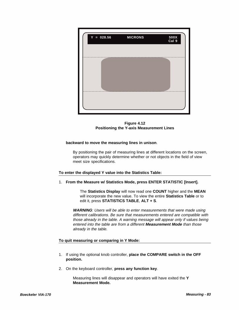
Boeckeler VIA-170 Measuring - 83
Figure 4.12Positioning the Y-axis Measurement Lines
Y = 028.56 MICRONS 500XCal 9
backward to move the measuring lines in unison .
By positioning the pair of measuring lines at different locations on the screen,operators may quickly determine whether or not objects in the field of viewmeet size specifications.
To enter the displayed Y value into the Statistics Table:
1. From the Measure w/ Statistics Mode, press ENTER STATISTIC [Insert].
The Statistics Display will now read one COUNT higher and the MEANwill incorporate the new value. To view the entire Statistics Table or toedit it, press STATISTICS TABLE , ALT + S .
WARNING: Users will be able to enter measurements that were made usingdifferent calibrations. Be sure that measurements entered are compatible withthose already in the table. A warning message will appear only if values beingentered into the table are from a different Measurement Mode than thosealready in the table.
To quit measuring or comparing in Y Mode:
1. If using the optional knob controller, place the COMPARE switch in the OFFposition.
2. On the keyboard controller, press any function key .
Measuring lines will disappear and operators will have exited the YMeasurement Mode.

84 - Measuring Boeckeler VIA-170
X and Y Measurement
To measure in the XY Mode:
1. On the keyboard controller, press the XY MEASURE [ F9] key .
2. If needed, sequence through each Measurement Mode until two horizontallines and two vertical lines are displayed over the video image (refer to Figure4.13).
This is the XY Measurement Mode . At this point only the top and left lines arepositionable or active.
Figure 4.13 XY Measurement Mode
X = 052.07 MICRONS 500XY = 028.56 Cal 9
3. If measurements will be used in statistical calculations, press MEASURE W/STATS, ALT + XY MEASURE [ F9].
The Statistics Display with the current COUNT and MEAN will appear inthe lower left corner of the screen, along with the measuring lines. If thecurrent MEAN is INVALID, this means that there are measurements in theStatistics Table that are incompatible with XY Mode measurements. Toclear the Statistics Table , press CLEAR STATS, ALT + D .
4. Select the desired line pattern (dashed or solid) by pressing the CTRL + XYMEASURE [F9] key combination .
5. If not already selected, select the desired calibration number by pressing theSELECT CALIBRATION # [ Scroll Lock ] key .
The Select Calibration # Menu will appear on screen. Follow instructions toselect the desired CAL# . Operators will be automatically returned to the XY

Boeckeler VIA-170 Measuring - 85
Figure 4.14Positioning the X and Y
Measurement Lines
X = 066.72 Microns 500XY = 024.10 Cal 9
COUNT = 004MEAN X = 066.28MEAN Y = 025.47
B. Be certain to position the inside edges of the measuring linesagainst the object to be measured .
Refer to Positioning the Lines in the Calibration section of this manual.
C. Press ENTER .
The right and bottom measuring lines are now active.
D. Position the right measurement line along the right perimeter ofthe object to be measured. Position the bottom measurement linealong the bottom perimeter of the object to be measured . (refer toFigure 4.14).
E. Be certain to position the inside edges of the measuring linesagainst the object to be measured .
Refer to Positioning the Lines in the Calibration section of this manual.
The distance between the two vertical measurement lines will continuously be
Measurement Mode , and the selected CAL# will be displayed in the upperright corner of the screen.
5. To measure the object in view:
A. Position the left measurement line along the left perimeter of theobject to be measured. Position the top measurement line along thetop perimeter of the object to be measured (refer to Figure 4.14).

86 - Measuring Boeckeler VIA-170
displayed in the upper left-hand corner of the video screen as X= . The dis-tance between the two horizontal measurement lines will continuously bedisplayed in the upper left-hand corner of the video screen as Y= .
To perform comparison measurements in XY Mode:
1. Position all four measuring lines at a fixed distance apart.
2. If operators have an optional knob controller, set the COMPARE switch to the ONposition. Rotate the right knob to move the vertical measuring lines in uni-son. Rotate the left knob to move the horizontal measuring lines in unison .
3. If operators have an optional joystick controller, tilt the joystick left or right tomove vertical the measuring lines in unison . Tilt the joystick forward orbackward to move the horizontal measuring lines in unison.
By positioning the pair of measuring lines at different locations on the screen,operators may quickly determine whether or not objects in the field of viewmeet size specifications.
To enter the displayed X and Y values into the Statistics Table:
1. From the Measure w/ Statistics Mode, press ENTER STATISTIC [Insert].
The Statistics Display will now read one COUNT higher and the MEANwill incorporate the new value. To view the entire Statistics Table or to editit, press STATISTICS TABLE , ALT + S .
WARNING: Users will be able to enter measurements that were made usingdifferent calibrations. Be sure that measurements entered are compatible withthose already in the table. A warning message will appear only if values beingentered into the table are from a different Measurement Mode than thosealready in the table.
To quit measuring or comparing in XY Mode:
1. If using the optional knob controller, place the COMPARE switch in the OFFposition.
2. On the keyboard controller, press any function key .
Measuring lines will disappear and operators will have exited the XY Measure-ment Mode.

Boeckeler VIA-170 Measuring - 87
Point-to-Point Measurement
To measure in the P-P (Point-to-Point) Mode:
1. On the keyboard controller, press the XY MEASURE [ F9] key .
2. If needed, sequence through each of the four Measurement Modes until twocross hairs cursors are displayed over the video image (refer to Figure 4.15).
This is the P-P (Point-to-Point) Measurement Mode . At this point, only onecross hairs cursor is positionable or active.
Figure 4.15P-P Measurement Mode
E3. If measurements will be used in statistical calculations, press MEASURE W/STATS, ALT + XY MEAURE [ F9].
The Statistics Display with the current COUNT and MEAN will appear inthe lower left corner of the screen, along with the cross hairs cursors. If thethe current MEAN is INVALID, this means that there are measurements inthe Statistics Table that are incompatible with P-P Mode measurements.To clear the Statistics Table , press CLEAR STATS, ALT + D .
4. If not already selected, select the desired calibration number by pressing theSELECT CALIBRATION # [Scroll Lock ] key .
The Select Calibration # Menu will appear on screen. Follow instructions toselect the desired CAL# . Operators will be automatically returned to the P-PMeasurement Mode and the selected CAL# will be displayed in the upperright corner of the screen.
D = 037.55 MICRONS 500XCal 9

88 - Measuring Boeckeler VIA-170
Figure 4.16Positioning the Point-to-Point
Cross Hairs Cursors
5. To measure the object in the field of view:
A. Position the first active cross hairs at the first point of theobject to be measured (refer to Figure 4.16).
B. Be certain to position the inside edges of the cross hairs against theobject to be measured . Refer to Positioning the Lines in the Calibrationsection of this manual.
C. Press ENTER .
The second cross hairs cursor is now active.
D. Position the second active cross hairs at the second point of theobject to be measured (refer to Figure 4.16).
E. Be certain to position the inside edges of the cross hairs againstthe object to be measured .
Refer to Positioning the Lines in the Calibration section. The distance betweenthe two cross hairs will continuously be displayed in the upper left-hand cornerof the video screen as D= .
The COMPARE function that is available with the optional knob and joystickcontrollers is not used in the P-P Measurement Mode.
D = 042.85 MICRONS 500XCal 9

Boeckeler VIA-170 Measuring - 89
To quit measuring in P-P Mode:
1. On the keyboard controller, press any function key .
The cross hairs will disappear and operators will have exited the P-P Measure-ment Mode.
To enter the displayed distance into the Statistics Table:
1. From the Measure w/ Statistics Mode, press ENTER STATISTIC [Insert].
The Statistics Display will now read one COUNT higher and the MEANwill incorporate the new value. To view the entire Statistics Table or to editit, press STATISTICS TABLE , ALT + S .
WARNING: Users will be able to enter measurements that were made usingdifferent calibrations. Be sure that measurements entered are compatible withthose already in the table. A warning message will appear only if values beingentered into the table are from a different Measurement Mode than thosealready in the table.
Angle Measurement
To determine an angle with the VIA-170, operators will place four or more points on thevideo overlay, thereby defining two lines. One pair of points will define one line seg-ment (the first leg), and a second pair of points will define a second line segment (thesecond leg). The VIA-170 will automatically determine the angle of the vertex formedby these two lines, even if the vertex is only implied, that is, not visible within the field ofview.
To measure in the ANGLE Mode:
1. On the keyboard controller, press the ANGLES/CIRCLES [ F10] key .
2. Sequence through the two Measurement Modes until the "A=" display isshown in the upper left corner of the screen (refer to Figure 4.17).
This is the ANGLE Measurement Mode .
3. If measurements will be used in statistical calculations, press MEASURE W/STATS, ALT + XY MEASURE [ F9].
The Statistics Display with the current COUNT and MEAN will appear inthe lower left corner of the screen, along with the cross hairs cursor. If thecurrent MEAN is INVALID, this means that there are measurements in theStatistics Table that are incompatible with Angle Mode measurements.To clear the Statistics Table , press CLEAR STATS, ALT + D .

90 - Measuring Boeckeler VIA-170
Figure 4.17ANGLE Mode
A = Degrees 500XLeg 1 -- SPACE for Leg 2 Cal 1
3. If not already selected, select the desired calibration number by pressing theSELECT CALIBRATION # [Scroll Lock] key .
The Select Calibration # Menu will appear on screen. Follow instructions toselect the desired CAL# . Operators will be automatically returned to theANGLE Measurement Mode and the selected CAL# will be displayed in theupper right corner of the screen.
4. To measure the first leg of the angle:
A. Position the first cross hairs cursor along one leg of the angle to bemeasured (refer to Figure 4.18).
B. Be certain to position the inside edges of the cross hairs against theobject to be measured . Refer to Positioning the Lines in the Calibrationsection of this manual.
NOTE: The top left of the data line will display LEG 1, to remind users they aremeasuring the first leg of the angle.
C. Press ENTER .
The first point will be anchored, and a second cross hairs cursor willappear, ready for positioning. If the Angle Display is on, a line represent-ing the first leg of the angle will continuously connect the first and secondpoints.
D. Turn on or off the Angle Display to aid in point placement by pressingSHOW/HIDE ANGLE WHILE MEASURING (ALT + A) .

Boeckeler VIA-170 Measuring - 91
NOTE: Turning on the Angle Display can help users align each leg of theangle against the object in the field of view. Turning off the angle display maybe preferred when users need an unobstructed view of the object beingmeasured.
E. Repeat steps A-D to position the second, third, and etc., points alongthe same leg of the angle being measured (refer to Figure 4.18).
After each point is anchored a cross hairs cursor will appear, ready forpositioning. If the Angle Display is on, the line representing the first leg ofthe angle will now transverse the anchored points.
NOTE: Users may anchor up to 20 points per leg. However, in doing so, eachpoint will become increasingly less significant in determining the line segment.For this reason, we recommend not exceeding 4-5 points per leg.
5. To measure the second leg of the angle:
A. Press the SPACE BAR .
The display in the upper left of the screen will change from LEG 1 to LEG2. Users can now place points along the second leg of the angle.
B. Position the first cross hairs cursor along the second leg of the anglebeing measured .
C. Be certain to position the inside edges of the cross hairs againstthe object to be measured (refer to Figure 4.18 ). Refer to Positioning theLines in the Calibration section.
The distance between the two cross hairs will continuously be displayed inthe upper left-hand corner of the video screen as A= .
Figure 4.18ANGLE Mode, Placing the First Leg
(angular object represents image being measured)
A = Degrees 500XLeg 2 -- SPACE for Leg 1 Cal 1

92 - Measuring Boeckeler VIA-170
D. Press ENTER .
The first point will be anchored and a second cross hairs cursor will appearready for positioning. If the Angle Display is on, the line representing thesecond leg of the angle will also appear, continuously connecting the firstand second points.
NOTE: At this point, the measurement of the implied angle will be dis-played in the upper left of the screen. However, because the second crosshairs cursor is still positionable, the reading will change with any movementof that cursor. If this is not desired, the measurement can be made final byanchoring one or more additional cursors.
E. Repeat steps A-D to position the second, third and etc., points alongthe second leg of the angle (refer to Figure 4.19).
After each point is anchored a cross hairs cursor will appear, ready forpositioning. If the Angle Display is on, the line representing the second legof the angle will now transverse the anchored points.
NOTE: When two lines are defined, four angles are also defined (refer toFigure 4.20). The VIA-170 measures and displays only one of the angles.Knowing one angle, operators can quickly perform the simple calculationsdepicted in Figure 4.20 in order to determine the measurements of the remain-ing angles, if desired. Use these formulas to calculate other angles.
NOTE: While placing points along the second leg, there are certain caseswherein an obviously obtuse angle may suddenly "appear" to display an acutemeasurement; or an acute angle may suddenly display an obtuse measure-ment. This is not an error. The new measurement displayed is actually of thecomplementary angle, from which the first angle measurement can be easily
Figure 4.19ANGLE Mode, Placing the Second Leg
(angular object represents image being measured)
A = 26.5 Degrees 500XSecond Leg Cal 1

Boeckeler VIA-170 Measuring - 93
Figure 4.20Measuring Other Angles
When One Angle is Known
Angle 1 = X Angle 2 = 360minus Angle 1
Angle 3 = 180minus Angle 1
Angle 4 = 180plus Angle 1
To measure an angle using only three points:
1. Place the first and second points of the first leg as described in Step #4, onpages 90-91 .
The second point will be anchored. Users should be sure not to position the secondactive cross hairs cursor. Instead, let it lie directly on top of the second point of thefirst leg (it will be anchored there).
2. Press the SPACE BAR to activate the second leg of the angle .
To quit measuring in ANGLE Mode:
1. On the keyboard controller, press any function key .
The cross hairs and any measuring lines will disappear and operators will haveexited the ANGLE Mode.
To enter the displayed angle into the Statistics Table:
1. From the Measure w/ Statistics Mode, press ENTER STATISTIC [Insert].
The Statistics Display will now read one COUNT higher and the MEANwill incorporate the new value. To view the entire Statistics Table or to editit, press STATISTICS TABLE , ALT + S .
WARNING: Users will be able to enter measurements that were made usingdifferent calibrations. Be sure that measurements entered are compatible withthose already in the table. A warning message will appear only if values beingentered into the table are from a different Measurement Mode than thosealready in the table.
determined. Due to the way the averaging algorithm of the VIA-170 works,there will be times when the VIA-170 will switch from measuring angle A tomeasuring angle B. In either case, the complementary angle can be deter-mined using the formulas in Figure 4.20.

94 - Measuring Boeckeler VIA-170
Figure 4.21Measuring an Angle Using Three Points
A = 26.5 Degrees 500XLeg 2 -- SPACE for Leg 1 Cal 1
To quit measuring in Angles Mode:
1. On the keyboard controller, press any function key .
The cross hairs will disappear and operators will have exited the AngleMeasurement Mode.
To clear points:
1. While in the ANGLES Mode, press CLEAR POINTS (CTRL + ANGLES/CIRCLES[F10] ).
All points will be cleared from the overlay and an active cursor will remain. Allanchored markers present in the overlay will remain unaffected by this clear.
3. Press ENTER .
The first point of the second leg will be anchored on top of the previous leg'scursor. Another cross hairs cursor will appear, ready for positioning. The linerepresenting the second leg of the angle will also appear (refer to Figure 4.21).
4. Position the second point along the second leg of the angle being measured.
5. Press ENTER.
The last point will of the second leg will be anchored. The measurement of theangle created by the two lines is displayed in the upper left-hand corner of thevideo screen.

Boeckeler VIA-170 Measuring - 95
Circle MeasurementTo determine the radius or circumference of a circle with the VIA-170, operators willplace three or more points on the video overlay, thereby defining a circle. The VIA-170will automatically determine the radius and circumference of that circle, even if thecircle is only implied, that is, not entirely visible in the field of view. Measurementsreflect those of a perfect circle, and are used only as approximations when measuringirregularly shaped circles or ellipses.
To measure in the CIRCLE MODE:
1. On the keyboard controller, press the ANGLES/CIRCLES [F10] key.
2. Sequence through the two Measurement Modes until the "R= C=" display isshown in the upper left corner of the screen (refer to Figure 4.22).
This is the CIRCLE Measurement Mode .
3. If measurements will be used in statistical calculations, press MEASURE W/STATS, ALT + XY MEASURE [ F9].
The Statistics Display with the current COUNT and MEAN will appear inthe lower left corner of the screen, along with the cross hairs cursor. If thecurrent MEAN is INVALID, this means that there are measurements in theStatistics Table that are incompatible with Circle Mode measurements.To clear the Statistics Table , press CLEAR STATS, ALT + D .
Figure 4.22CIRCLE Measurement Mode
(circle represents image being measured)
R = MICRONS 500XC = Cal 9

96 - Measuring Boeckeler VIA-170
4. If not already selected, select the desired calibration number by pressing theSELECT CALIBRATION # [Scroll Lock ] key .
The Select Calibration # Menu will appear on screen. Follow instructions toselect the desired CAL# . Operators will be automatically returned to theCIRCLE Measurement Mode and the selected CAL# will be displayed in theupper right corner of the screen.
5. To measure the object in view:
A. Position the first cross hairs cursor along the perimeter of the circularimage being measured. Press ENTER.
The first point will be anchored and a second cross hairs cursor will ap-pear, ready for positioning. If the Circle Display is on, a circular graphicrepresenting the circle being measured will also be displayed.
B. Turn on or off the Circle Display to aid in point placement by pressingSHOW/HIDE CIRCLE WHILE MEASURING (ALT + C) .
NOTE: Turning on the Circle Display can help users align the circle againstthe object in the field of view. Turning off the angle display may be preferredwhen users need an unobstructed view of the object being measured.
C. Position the second cursor along the perimeter of the circular imagebeing measured. Press ENTER.
The second point will be anchored and a third cross hairs cursor willappear, ready for positioning.
Figure 4.23 CIRCLE Mode:
Anchoring the Third Point (circle represents image being measured)
R = 034.52 MICRONS 500XC = 216.87 Cal 9

Boeckeler VIA-170 Measuring - 97
NOTE: At this point, the measurement of the implied circle will be displayed inthe upper left of the screen. However, because the third cross hairs cursor isstill positionable, the display will change with any movement of the cursor. Ifthis is not desired, the measurement can be made final by anchoring the thirdor final cursor.
C. Position the third point along the perimeter of the circular imagebeing measured. Press ENTER.
The third point will be anchored and the radius and circumference of thecircular image will be displayed in the upper left-hand corner of the videoscreen (refer to Figure 4.23). A fourth cross hairs cursor will have appeared,ready to begin a new measurement, or add additional points to the currentmeasurement. If the latter, the measurement will change slightly as each newpoint is added.
NOTE: While users can define an arc or circle using a minimum of three points,for best results, we recommend placing more points, preferably 8 or 16, sincethese can be placed equidistant in a triangular pattern. Whatever the numberof points used, keep in mind the triangular pattern while placing points. Thepattern is much like cutting a pie: first cut it in half with points 1 and 2, then inquarters with points 3 and 4, then in eighths with points 5, 6, 7, and 8; and soon.
To enter the displayed radius and circumference into the Statistics Table:
1. From the Measure w/ Statistics Mode, press ENTER STATISTIC [Insert].
The Statistics Display will now read one COUNT higher and the MEANwill incorporate the new value. To view the entire Statistics Table or to editit, press STATISTICS TABLE , ALT + S .
WARNING: Users will be able to enter measurements that were made usingdifferent calibrations. Be sure that measurements entered are compatible withthose already in the table. A warning message will appear only if values beingentered into the table are from a different Measurement Mode than thosealready in the table.
To clear points:
1. While in the CIRCLES Mode, press CLEAR POINTS (CTRL +ANGLES/CIRCLES[F10] ).
All points will be cleared from the overlay and an active cursor will remain. Allanchored markers present in the overlay will remain unaffected by this clear.
To quit measuring in Circles Mode:
1. On the keyboard controller, press any function key .
The cross hairs will disappear and operators will have exited Circle Measure-ment Mode.

98 - Measuring Boeckeler VIA-170
Count Measurement
To count cells/particles in the COUNT Mode:
1. On the keyboard controller, press the COUNT [ F11] key .
This is the COUNT Measurement Mode (refer to Figure 4.24). The letter A:and measurement display, will appear in the upper left of the screen. Thisdisplay represents the total count of all specimens marked with the tag A. Apositionable counting cursor " " is also present in the overlay, along with anyanchored markers.
2. Select a different marker overlay (#1 - #10), if desired , by pressing the PREVOVERLAY [Page Up] key or the NEXT OVERLAY [Page Down] key.
NOTE: Sized grids, scales, circles or boxes created in the Marker Mode canassist in counting by providing users with a reference for distance, area, etc.
Figure 4.24Count Mode
3. To count the objects in view:
A. Position the counting cursor over the object to be counted.
B. Press ENTER on the keyboard controller - or - press the pen tip intothe screen on top of the cursor with the optional light pen. Selectbuttons on other optional controllers will achieve this same function.
The cursor will anchor a tag A over the object. The cursor will remainpositionable, ready to tag and count another object. The resulting count willbe displayed in the upper left of the screen (refer to Figure 4.25).
NOTE: A tag can be erased by pressing the UNDO [delete] key.
A = 0000

Boeckeler VIA-170 Measuring - 99
C. Repeat the above two steps until all the objects are counted whichbelong to the A group.
D. To count a second group of objects visible in the same field of view,press the COUNT [F11] key again - or - press the barrel button on thelight pen .
Figure 4.25Counting Objects, Group A
AA
A
AA
A
AA
AAA
AAAA
AA
A
AAA
AA
AAA
A = 0026
The letter B: and measurement display, will appear in the upper left of thescreen. This display represents the total count of all specimens markedwith a B tag. The positionable counting cursor will also be present in theoverlay, along with any anchored markers.
E. Anchor the B tag on each object until all the objects are counted whichbelong to the B group.
F. If desired, repeat the above two steps to anchor C through J tags (referto Figure 4.26 for an example of count combinations).
NOTE: To cycle backwards through the alphabet (J down to A), press theSHIFT key plus the COUNT [F11] key.
4. To obtain a final count of all tagged objects:
A. After all desired tags are anchored on screen, repeatedly press theCOUNT [F11] key. A display of the final count for each tag will appear onscreen in the upper left corner.
NOTE: Measure w/ Statistics is not active in COUNT Mode .

100 - Measuring Boeckeler VIA-170
AA
A
AA
A
AA
AAA
AAAA
AA
A
AAA
AA
AAA
B
BB
BB
B
B
BC
C
C C C
D
C
C
C
C
DD
D
D
DDD
E
E
EE
E
E
E
E
E = 0008
Figure 4.26Combination of Tags
5. To clear the screen of tags while retaining the count:
A. If operators wish to retain totals while continuing to count on a new sampleor video image, press the CLEAR [End] key .
A Clear Tags Menu will appear on screen, giving users two options inclearing tags: to clear all tags (A-J) and all counts - or - to clear all tags (A-J) and retain all counts.
B. Select the CLEAR TAGS WHILE RETAINING COUNT option, and SAVEto confirm the desired option.
The screen will be cleared of markers, and all counts will remain as theywere before pressing CLEAR [End] .
6. To clear the screen of all tags and all counts:
A. If operators wish to zero out all counts and erase all tags (A-J), press theCLEAR [End] key .
A Clear Tags Menu will appear on screen, giving users two options inclearing tags: to clear all tags (A-J) and all counts - or - to clear all tags (A-J) and retain all counts.
B. Select the CLEAR ALL TAGS AND COUNTS option, and SAVE toconfirm the desired option.
The screen will be cleared of markers, and all counts will be displayed as0000 (refer to Figure 4.24). NOTE: An "undelete" command, CTRL +OVERLAY [Home] , will retreive only the most recently erased tag.
7. To quit the COUNT Mode press any function key .

Boeckeler VIA-170 Measuring - 101
Area/Chords Measurement
To measure AREA in the AREA/CHORDS Mode:
1. Define the perimeters of the area to be measured.
A. On the keyboard controller, select, size and anchor a marker that en-closes an empty shape (e.g., a circle or box) - or - create a closed shapewith straight lines or freehand drawing lines .
NOTE: Freehand drawing is available only with the optional light pen or mousedevice. It is important to understand that the area will be calculated from withinthe inside edges of the shape or drawn line. The entire illuminated line will notbe calculated in the area. Additionally, any line segment or marker that fallswithin the shape will be discounted from the total area measurement. Thismeans that in drawing one continuous line, any overlap of endpoints must takeplace outside of the drawn shape (refer to Figure 4.27).
Figure 4.27Drawing Perimeter of Area
2. After the shape or drawing is complete and anchored, press the AREA/CHORDS[F12] key .
This is the AREA/CHORDS Measurement Mode (refer to Figure 4.28). Apreference arrow is positioned after the area display (A), designating the optionwhich is currently active. A positionable cross hairs cursor is present in theoverlay, along with the drawn shape and any other anchored markers.
3. If measurements will be used in statistical calculations, press MEASURE W/STATS, ALT + XY MEAURE [ F9].
The Statistics Display with the current COUNT and MEAN will appear in

102 - Measuring Boeckeler VIA-170
the lower left corner of the screen, along with the cross hairs cursor. If thethe current MEAN is INVALID, this means that there are measurements inthe Statistics Table that are incompatible with Area Mode measurements.To clear the Statistics Table , press CLEAR STATS, ALT + D .
4. If not already selected, select the desired calibration number by pressing theSELECT CALIBRATION # [ Scroll Lock ] key .
The Select Calibration # Menu will appear on screen. Follow instructions toselect the desired CAL# . Operators will be automatically returned to the AREA/CHORDS Measurement Mode and the selected CAL# will be displayed in theupper right corner of the screen. Operators may begin measuring when thedesired number is displayed.
5. To measure the area of the object in view:
A. Position the cross hairs cursor inside the shape to be measured (referto Figure 4.28).
B. Press the pen tip into the screen on top of the cursor - or - pressENTER on the keyboard controller. Select buttons on optional controllerswill achieve this same function.
The shape will fill with a solid color, and the resulting area will be displayed inthe upper left of the screen (refer to Figure 4.29).
NOTE: If the area outside of the shape filled as well as the inside, check to besure the shape was entirely closed.
6. To measure the area on a new sample or marker overlay:
Figure 4.28Area Measurement Option
A= 000000.0000 MICRONSD1= 000.00 1000XD2= 000.00 CAL 7

Boeckeler VIA-170 Measuring - 103
Figure 4.29Calculating the Area
A= 001547.6787 MICRONSD1= 000.00 1000XD2= 000.00 CAL 7
A. Press UNDO [delete] to erase the drawn shape or marker - or -
Change to another marker overlay (1-10) by pressing the PREV OVER-LAY [Page Up] key or NEXT OVERLAY [Page Down] key.
Repeat steps 1 through 5.
To enter the displayed area into the Statistics Table:
1. From the Measure w/ Statistics Mode, press ENTER STATISTIC [Insert].
The Statistics Display will now read one COUNT higher and the MEANwill incorporate the new value. To view the entire Statistics Table or to editit, press STATISTICS TABLE , ALT + S .
WARNING: Users will be able to enter measurements that were made usingdifferent calibrations. Be sure that measurements entered are compatible withthose already in the table. A warning message will appear only if values beingentered into the table are from a different Measurement Mode than thosealready in the table.
To quit measuring in Area Mode:
1. On the keyboard controller, press any function key .
The cross hairs will disappear and operators will have exited AreaMeasurement Mode.

104 - Measuring Boeckeler VIA-170
Figure 4.30Chord Measurement Option
AREA 1
A= 001547.6787 MICRONSD1= 000.00 1000XD2= 000.00 CAL 7
To measure CHORDS in the AREA/CHORDS Mode:
1. To activate the first chord option (D1), press the AREA/CHORDS [F12] key sothat the preference arrow is positioned next to the D1 display - or - press thepen tip into the D1 display to select it.
NOTE: To cycle backwards through the area and chord options, press theSHIFT key plus the AREA/CHORDS [F12] key.
The preference arrow will be positioned after the D1= xxx.xx display, and across hairs cursor labelled with a "1" will appear on screen (refer to Figure4.30). If operators enter this mode immediately after calculating the area, thearea measurement will continue to be displayed in the upper left of the screen.The filled area of the shape will disappear and the word "AREA" will appear onthe shape to remind operators which image corresponds with the area mea-surement display (refer to Figure 4.30).
2. Position the cursor along the perimeter of the object. This will be the firstendpoint of the distance displayed as D1.
NOTE: In this mode, the VIA-170 will measure the distance from the center ofthe cursor. Also, the Measure w/ Statistics Mode is only active for enteringarea measurements. Chord measurements cannot be entered.
3. Anchor the cursor by pressing the pen tip into the screen on top of the cursor orby pressing ENTER on the keyboard controller. The select buttons on optionalcontrollers will achieve this same function.
The cursor will be anchored and the second cursor will appear, ready forpositioning.

Boeckeler VIA-170 Measuring - 105
Figure 4.31Measuring the D1 Chord
AREA
1
1
A= 001547.6787 MICRONSD1= 013.45 1000XD2= 000.00 CAL 7
4. Position the second cursor along the perimeter of the object. This will be thesecond endpoint of D1.
NOTE: Be sure to position the cursor so that its center lies just inside theline representing the object's perimeter.
5. Anchor the second cursor by pressing the pen tip into the screen on top of thecursor or by pressing ENTER on the keyboard controller. The select buttons onoptional controllers will achieve this same function.
The second cursor will be anchored and a straight line will connect the twoendpoints. The resulting measurement is displayed in the upper left of thescreen (refer to Figure 4.31).
6. Measure the second chord or distance:
A. Press the AREA/CHORDS [F12] key to activate the D2 option - or - pressthe pen tip into the D2 display to select it.
The preference arrow will be positioned after the D2= xxx.xx display and across hairs cursor labelled with a "2" will appear on screen (refer to Figure4.32).
B. Position the cursor along the perimeter of the object. This will be thefirst endpoint of D2, which can be any point-to-point measurement.
NOTE: In this mode, the VIA-170 will measure a distance from the centerof the cursor.
C. Anchor the first cursor by pressing the pen tip into the screen on top ofthe cursor or by pressing ENTER on the keyboard controller. The select

106 - Measuring Boeckeler VIA-170
Figure 4.32Measuring the D2 Chord
AREA
1
2
2
A= 001547.6787 MICRONSD1= 013.45 1000XD2= 086.77 CAL 7
buttons on optional controllers will achieve this same function.
The first cursor will be anchored and the second cursor will appear, readyfor positioning.
D. Position the second cursor along the perimeter of the object. This willbe the second endpoint of D2.
E. Anchor the second cursor by pressing the pen tip into the screen on topof the cursor or by pressing ENTER on the keyboard controller. Selectbuttons on optional controllers will achieve this same function.
The second cursor will be anchored and a straight line will connect the twoendpoints. The resulting measurement is displayed in the upper left of thescreen (refer to Figure 4.32).
7. To repeat the same chord or distance measurement position and anchor theactive cursor as the first endpoint of the new chord (refer to step #4).
8. To measure chords on a new sample or marker overlay:
A. Press UNDO [delete] to erase the drawn shape or marker - or - changeto another marker overlay (1-10) by pressing the PREV OVERLAY [PageUp] key or NEXT OVERLAY [Page Down] key.
B. Repeat steps 1 through 5 .
To quit measuring in Chords Mode:
1. On the keyboard controller, press any function key .

Boeckeler VIA-170 Measuring - 107
Timers
To use the Timer w/XY Measurements :
1. Enter XY Measurement by repeatedly pressing XY MEASURE [F9] until thedesired mode is displayed.
2. Position the lines or cursors at the desired distance apart .
3. Press the TIMER W/XY MEASURE key combination CTRL + COUNT [F11] .
The TIMER Display will appear in the lower right corner of the screen, alongwith the measurement overlay and any markers anchored in that overlay (referto Figure 4.33)
Figure 4.33Timer w/XY Measurement
00 : 00 : 00 . 00
4. To time an event in the field of view:
A. To start the Timer, press the SPACE BAR.
The TIMER will continuously display elapsed time to the hundredths of asecond. Measurement lines/cursors can be positioned while timer is active.
B. To stop the TIMER, press the SPACE BAR a second time.
C. To zero out the TIMER, press the SPACE BAR a third time.
NOTE: Steps A through C can be repeated as often as desired.
5. To remove the TIMER from the display, press CTRL + COUNT [F11] .
NOTE: Timer displays cannot be entered in the Statistics Table.

108 - Measuring Boeckeler VIA-170
Figure 4.34Timer w/ Markers Mode
00:00:00.00To ready timer press enter. Toexit timer, press any marker key.
To use the Timer w/ Markers :
1. On the keyboard controller, press CTRL + AREA/CHORDS [ F12].
The TIMER Display will appear along with any anchored markers that might beon the overlay (refer to Figure 4.34)
2. To time an event in the field of view:
A. Press the SPACE BAR to ready the TIMER .
The TIMER display will show "TIMER READY ."
B. Press the SPACE BAR a second time to start the TIMER .
The TIMER will continuously display elapsed time, to the hundredths of asecond.
C. Press the SPACE BAR a third time (or any other function key) to stopthe TIMER. Note the time elapsed .
NOTE: The TIMER display will show "TIMER READY ."
D. Press SPACE BAR a fourth time to restart the TIMER from zero.
NOTE: Steps B through D can be repeated as often as desired.
NOTE: New markers cannot be anchored on an overlay while the timer isrunning.

Boeckeler VIA-170 Measuring - 109
To exit the TIMER Mode:
1. At "TIMER READY" status, press any function key except the SPACE BAR .
The TIMER display will offer the option to ready the TIMER again or to exit theTIMER.
2. Again, press any function key except the SPACE BAR .
The TIMER display will disappear. Users will have exited the TIMER Mode andthey will have entered the Marker Mode or another Measurement Mode,depending on which function key was pressed.


Boeckeler VIA-170 Communication - 111
Section Five:Communication

112 - Communication Boeckeler VIA-170

Boeckeler VIA-170 Communication - 113
USE OF THE RS-232 PORT
BASIC OPERATIONOutput is provided for most printers, terminals or computers that will accept data inASCII format and meet RS-232 electrical specifications.
Before operators use the RS-232 data output, they must verify the parameters for theirspecific printer or computer. The VIA-170 RS-232 parameters are factory set at 9600baud, 8 data bits, 1 stop bit, no parity, CR data block terminator, and output for Statis-tics Summary Only. All but two of these parameters are permanently fixed. Operatorsmay select baud rates, how statistics are output, and whether a data block terminatorhas a carriage return with a line feed or a carriage return without a line feed. To changethe factory setting for these three parameters, follow the instructions on the next page.
Also, before computers can use the RS-232 data output, they must be programmed toreceive the information. Program instructions are on page 116.

114 - Communication Boeckeler VIA-170
Before using the RS-232 data output capability, operators must verify and/or set theparameters through the RS-232 Set-Up Menu .
Set Up
E
To set up RS-232 communications:
1. Press CTRL+ RS-232 TRANSMIT [Print Screen].
The RS-232 Setup Menu will appear on the video screen (see Figure 5.1). TheBAUD RATE option will highlighted (factory setting is 9600 baud).
2. To change the baud rate, press the SPACE BAR to toggle through the availablebaud rates until the desired rate is displayed on screen .
Figure 5.1RS-232 Setup Menu
RS232 SETUP
CANCEL
BAUD RATE: 9600
SAVE
TERMINATOR:Carriage Return + Line Feed
STATISTICS:Send Statistics Summary Only
Press the space bar to toggle throughpossible selections.
3. Press ENTER .
The TERMINATOR option will be highlighted, ready for selection.
4. To change the terminator, press the SPACE BAR to toggle through the availableselections until the desired terminator return and line feed is displayed .
NOTE: The factory setting is a Carriage Return + Line Feed. Some printersrequire a line feed after the carriage return to advance the paper, some ad-vance it automatically. Set terminator to suit specific needs.
5. Press ENTER.
The STATISTICS option will be highlighted, ready for selection.
Boeckeler VIA-170 Communication - 115
6. To change how statistics will be ouput, press the SPACE BAR to toggle throughthe available selections until the desired option is displayed .
NOTE: SEND STATISTICS SUMMARY ONLY means the current count, mean,standard deviation, low value, high value, and range will be transmitted alongwith the displayed measurement. SEND ALL STATISTICS means that thesummary, the displayed measurement and all values that are in the StatisticsTable will be transmitted (up to 500 values). Values that have been deleted anddisplay a DEL in the table will be printed with a DEL following their transmis-sion. Users must be in a Measure w/Statistics Mode before transmittingstatistics.
7. Select SAVE or CANCEL to save or cancel displayed settings .
The RS-232 Setup Menu will automatically disappear and users will return to theircurrent Measurement or Marker Overlay .
Transmitting Data
When users are operating the VIA-170, they may transmit the measurements displayedin the upper left-hand corner of the measurement screen. Also, while in the MarkerMode , operators may transmit the marker coordinates and/or marker size (if displayedin the lower left-hand corner of the marker overlay). While in the Align Mode , theOffset Display can be transmitted. These display(s) must be present in order to betransmitted. While in a Measure w/ Statistics Mode , the displayed measurement andstatistics can be transmitted.
Measurement data is output in different forms depending on the specific mode of theVIA-170. In general, the measurement information on the screen is output to the remotedevice. When the VIA-170 is in X Mode , X = x.xxx will be transmitted (x.xxx being theactual measurement displayed on the screen). In Y Mode , Y= y.yyy is sent. In XYMode , X= x.xxx Y= y.yyy is sent. In P-P Mode , D=d.ddd is sent. In ANGLE MODE, A=aaa.a is sent, and in CIRCLE MODE, R= rrrr. C= cccc. is sent. In the COUNT Mode ,all nonzero counts will be transmitted by tag letter groups, e.g., A= aaaa. B= bbbb. C=cccc., etc. (users only have to transmit once to send all counts). In AREA/CHORDSMode , A= xx.xxxxxxxx D1= x.xxxx D2 = x.xxxx is sent. In either of the TIMER Modes(marker or measurement), TIMER = xx:xx:xx.xx will be transmitted. All measurementdata will be followed by a carriage return and the UNITS displayed in the measurementoverlay (e.g., MICRONS, DEGREES). An optional line feed can be selected from theterminator option in the RS-232 Menu .
On the keyboard controller, the transmit function is operated by pressing the RS-232TRANSMIT [Print Screen] key. On either the knob or joystick controller, the transmitfunction is operated by the button labeled TRANSMIT. At any time, operators maysimply press the RS-232 TRANSMIT key or button, and any marker or measurementreadings on screen will be transmitted through the RS-232 port.
NOTE: In some cases, a leading zero is transmitted which causes a fifth digit tobe transmitted. This is the case when the decimal point is moved farthest to theleft. The transmission will be, then, X = 0.xxxx.
116 - Communication Boeckeler VIA-170
If transmitting TIMER data, users must allow the transmission to completebefore restarting the TIMER again.
Program to Test Port
To test the RS-232 computer connection to the VIA-170, a program will need to bewritten for the computer. The requirements for such a program are as follows:
1. a personal computer with at least one serial port.
2. a version of BASICA, GWBASIC or Quick BASIC installed on the computer (otherversions of BASIC may or may not have the same syntax as the program printedbelow).
3. a cable to connect the VIA-170 RS-232 port to the computer port (VIA-170 unitshave DB-9 connectors for RS-232 output).
4. the VIA-170 powered up and in one of the Measurement Modes , with camera andvideo monitor also operating (be sure the camera is turned on first).
The program is as follows:
10 REM PROGRAM TO TEST RS-232 INTERFACE ON VIA PRODUCTS20 REM SET THE VIA FOR 9600 BAUD THRU ITS RS232 MENU30 PRINT "NOW PRESS TRANSMIT BUTTON..."40 OPEN "COM2:9600,N,8,1,DS"AS #150 INPUT #1, X$60 PRINT X$70 GOTO 50
Line 40 of this program can be changed to specify any COM port the user prefers.
When this program is run on the computer, users will be prompted to press theRS-232 TRANSMIT [Print Screen] key on the VIA-170. If the VIA-170 RS-232 connec-tion is functioning properly, the measurement reading on the VIA-170 will be displayedon the computer monitor. If there are any questions, users are welcome to call theService Department at Boeckeler Instruments, Inc., at (800) 552-2262 or (520) 573-7100.

Boeckeler VIA-170 Communication - 117
RS-232 Connector Pin OutThe RS-232RS-232RS-232RS-232RS-232 connector is on the rear panel of the VIA-170VIA-170VIA-170VIA-170VIA-170 and is a standard DB-9. Ifoperators are connecting the RS-232RS-232RS-232RS-232RS-232 connector to a printer or computer, they will needa cable which has nine pins on one end and a connector on the other end compatiblewith the printer or computer. Such cables are available at most electronic stores or fromyour Boeckeler dealer. The following pin out is standard except for pin 9 which isunused in the EIA Standard.
NOTE: When establishing an RS-232 communications link, the following tableshould be utilized. The most commonly asked pin out question is regardingpin #7.
Table 5.2Table 5.2Table 5.2Table 5.2Table 5.2RS-232 Connector Pin OutRS-232 Connector Pin OutRS-232 Connector Pin OutRS-232 Connector Pin OutRS-232 Connector Pin Out
PIN #PIN #PIN #PIN #PIN # NAMENAMENAMENAMENAME DESCRIPTIONDESCRIPTIONDESCRIPTIONDESCRIPTIONDESCRIPTION
1
2
5
6
7
8
9
DCD
RXD
GND
DSR
RTS
CTS
SEND
Data Carrier Detect. The VIA-170VIA-170VIA-170VIA-170VIA-170 sets this controlline to an active high.
Receive Data. The VIA-170VIA-170VIA-170VIA-170VIA-170 transmits data on thispin.
Signal Ground. This pin must be connected toThis pin must be connected toThis pin must be connected toThis pin must be connected toThis pin must be connected tosignal ground at the remote device connectorsignal ground at the remote device connectorsignal ground at the remote device connectorsignal ground at the remote device connectorsignal ground at the remote device connector.
Data Set Ready. The VIA-170VIA-170VIA-170VIA-170VIA-170 sets this controlline to an active high.
Request to Send. This control line must be setThis control line must be setThis control line must be setThis control line must be setThis control line must be setactive high.active high.active high.active high.active high.
Clear to Send. The VIA-170VIA-170VIA-170VIA-170VIA-170 sets this control lineto an active high.
Used as a foot pedal switch. This is not a stan-dard RS-232RS-232RS-232RS-232RS-232 signal; pin 9 is not used in thestandard fashion. Grounding this pin causes theinterface to send a block of data. This is anoptional method of initiating transmission whenthe VIA-170VIA-170VIA-170VIA-170VIA-170 is connected to a computer.

118 - Communication Boeckeler VIA-170
Using a Video PrinterThe VIA-170 is compatible with most video printers which may be purchased fromdealers around the country. Unlike text printers, which print only measurement coordi-nates on a tape roll similar to calculators, video printers will print everything displayedon the screen, including the camera image.
This means that the video printer will also print the active marker if it is present in theoverlay. In the Marking Mode , the active marker is the unanchored pointer, scale, grid,box, circle, crossline, date/time label or text line. If operators wish to print an overlaywithout the active marker, they may eliminate the marker from the overlay, therebyeliminating the extra marker from the printout. The following procedure eliminates theactive marker from the overlay.
To eliminate the active marker from the overlay before printing:
1. Press the OVERLAY [Home] key.
The desired overlay will appear on screen without the active marker and maybe printed at this point.
2. To recover the active marker, press the desired marker key .

Boeckeler VIA-170 Appendices - 119
Section Six:Appendices

120 - Appendices Boeckeler VIA-170

Boeckeler VIA-170 Appendices - 121
TROUBLESHOOTING GUIDE
The quality inspectors at Boeckeler Instruments test each VIA-170 for software andhardware performance prior to shipment. Therefore, most problems which operatorsencounter are related to installation. Table 6.1 below describes common problems andtheir solutions. If, after referring to this table, a problem still exists, call BoeckelerInstruments, Inc., at (800) 552-2262 and ask for technical assistance. There are nouser serviceable parts in the VIA-170. Do not open the cabinet.
Table 6.1Troubleshooting Guide
(continued on next page)
Symptoms Possible Solutions
1. Check that the VIA-170 is plugged into a liveoutlet.
2. On the back panel of the VIA-170 remove theplastic cover above the power supply connectorand check for a blown fuse. Replace the fuseonly with a BUSS MDL 1/2 amp slow blow. Seefull instructions page 125.
The green indicator lighton the front of theVIA-170 does not lightup.
Monitor does not lightup.
1. Check that the monitor is plugged into a liveoutlet.
2. Check that the monitor is switched on.
3. Check that the monitor brightness control isproperly adjusted.
Monitor displays ascrambled picture.
1. Check the horizontal hold control on the videomonitor for proper adjustment.
2. Check that the Dual Voltage Switch (110V/220V)located on the back panel of the VIA-170 isproperly set.

122 - Appendices Boeckeler VIA-170
Table 6.1Troubleshooting Guide
(continued)
Symptoms Possible Solutions
Monitor lights up butdoes not display apicture.
4. If the video source or monitor has a switch for 75OHM or high Z, ensure this switch is in the 75OHM position.
5. On the back panel of the VIA-170 remove theplastic cover above the power supply connectorand check for a blown fuse.
6. Bypass the VIA-170 by connecting the monitordirectly to the video source. If the video imagestill does not appear, have the video source andmonitor checked.
1. Adjust system parameters on the video outputdevice, monitor or camera (if in use)such ascontrast, gain, brightness, color, light and intensity.
2. Adjust the color or gray level of the VIA-170.
The VIA-170 graphicsbloom.
1. If using composite input, ensure that the 37-pinribbon cable between the VIA-170 and Y/Cor RGB interface is disconnected.
Light pen cursor ordrawing line will notfollow the light penover the darker area ofan image.
Video image onmonitor scrolls.
1. The image is too dark for the light pen to detectand alter the cursor/line position. Increase thebrightness of the monitor.
1. Check that the video source and VIA-170 areeach plugged into a live outlet.
2. Check that the video source and VIA-170 are bothswitched on.
3. Check that the coaxial cables are connected tothe proper BNC connectors on the video source,the VIA-170 and the monitor. Some cameras andmonitors have multiple output and input connec-tors. Consult your video manuals for correctconnection information.
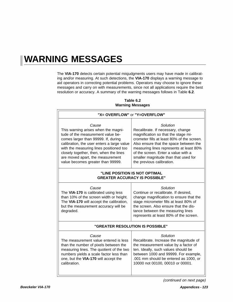
Boeckeler VIA-170 Appendices - 123
WARNING MESSAGES
(continued on next page)
CauseThis warning arises when the magni-tude of the measurement value be-comes larger than 99999. If, duringcalibration, the user enters a large valuewith the measuring lines positioned tooclosely together, then, when the linesare moved apart, the measurementvalue becomes greater than 99999.
SolutionRecalibrate. If necessary, changemagnification so that the stage mi-crometer fills at least 80% of the screen.Also ensure that the space between themeasuring lines represents at least 80%of the screen. Enter a value with asmaller magnitude than that used forthe previous calibration.
"LINE POSITION IS NOT OPTIMALGREATER ACCURACY IS POSSIBLE"
CauseThe VIA-170 is calibrated using lessthan 10% of the screen width or height.The VIA-170 will accept the calibration,but the measurement accuracy will bedegraded.
SolutionContinue or recalibrate. If desired,change magnification to ensure that thestage micrometer fills at least 80% ofthe screen. Also ensure that the dis-tance between the measuring linesrepresents at least 80% of the screen.
"GREATER RESOLUTION IS POSSIBLE"
CauseThe measurement value entered is lessthan the number of pixels between themeasuring lines. The quotient of the twonumbers yields a scale factor less thanone, but the VIA-170 will accept thecalibration.
SolutionRecalibrate. Increase the magnitude ofthe measurement value by a factor often. Ideally, such values should bebetween 1000 and 99999. For example,.001 mm should be entered as 1000, or10000 not 00100, 00010 or 00001.
"X= OVERFLOW" or "Y=OVERFLOW"
The VIA-170 detects certain potential misjudgments users may have made in calibrat-ing and/or measuring. At such detections, the VIA-170 displays a warning message toaid operators in correcting potential problems. Operators may choose to ignore thesemessages and carry on with measurements, since not all applications require the bestresolution or accuracy. A summary of the warning messages follows in Table 6.2.
Table 6.2Warning Messages

124 - Appendices Boeckeler VIA-170
Table 6.2Warning Messages
(continued)
"MEMORY OVERFLOW"
CauseThe overlay has as many markers on itas can be stored.
SolutionSwitch to a new marker overlay or erasemarkers by using the CLEAR or UNDOkey.
CauseThe overlay has as many freehanddrawings on it as can be stored.
SolutionSwitch to a new marker overlay or erasedrawn lines by using the CLEAR orUNDO key. As drawn lines take aseparate memory than markers, erasingmarkers will not free memory space fordrawn lines.
"MARKERS PROTECTED" or "CALIBRATIONS PROTECTED"
Cause"Markers Protected" -- Certain markerson each overlay have been protected bya password holder. This means userscannot erase or clear them, althoughthey can save, align, delete and clearmarkers added to the protected overlay.They can even align and change thecolor of protected markers. This protec-tion ensures that an accidental erasureof certain markers does not take place.
Cause"Calibrations Protected" -- All calibra-tions have been protected by a pass-word holder. This means that oncecalibrations have been set, users arenot able to change them.
SolutionPassword holder can change markers.With the password, the user can enterthe Security Menu, unprotect markers,exit the menu, make all deletions andadditions needed in the marker overlay,then enter the Security Menu and protectthe markers as changed.
SolutionPassword holder can change calibra-tions. With the password, the user canenter the Security Menu, unprotectcalibrations, exit the menu, make newcalibrations in the Calibration Menu, thenenter the Security Menu and protect thecalibrations as changed.

Boeckeler VIA-170 Appendices - 125
In the VIA-170 Operating Instructions beginning on page 23, installation instructionsand illustrations refer to a 3/8 amp fuse. This is now a 1/2 amp fuse. In the "Trouble-shooting Guide" on page 121, the reference to a 3/8 amp fuse can be changed to read"1/2 amp fuse."
In addition, a spare fuse has been provided since the manual was written. Please notethe following procedures for replacing the fuse and using the spare fuse.
To replace a VIA-170 fuse with the spare fuse:
1. Power down the VIA-170 and disconnect the power cord from its attachmentto the back of the VIA-170 .
2. On the back of the VIA-170, to the right of the now-vacated power port, there is aremovable fuse holder identified by a drawing of a fuse. Dislodge the fuse holderby using a small slotted screwdriver .
3. Remove the exposed fuse from the holder .
4. Next to the exposed fuse is a black casing for the spare fuse. With a small tool,poke the top of the casing downward so that the spare fuse will be dislodgedalong with its envelope .
5. Remove the spare fuse from its envelope and return the envelope to thespare fuse casing .
6. Place the spare fuse in the exposed holder that was occupied by the old fuse .
7. Slide the entire fuse holder back into the back of the VIA-170 . The VIA-170power cord may now be attached and the unit powered up.
RELEASE NOTESFOR VIA-170 WITH 2 FUSES
Two 1/2 Amp Fuses

126 - Appendices Boeckeler VIA-170
The VIA-170 video image marker-measurement system now features a warmrestarting command.
A warm start, initiated by pressing CTRL+ALT+DELETE , restarts the VIA-170 whilesaving all calibrations, anchored markers, passwords, and menu settings. A warm startmay be desired when new controllers have been installed so that the VIA-170 candetect the new devices on power up.
For additional advice concerning restarts, call for technical assistance at(520)745-0001 or toll free in the U.S. at (800)552-2262.
RELEASE NOTESFOR VIA-170 WITH RESTART
Warm Restart Command

Boeckeler VIA-170 Appendices - 127
GLOSSARY
ACTION KEYS- keyboard function keys which allow users to perform actions or begin a given process.These keys are used with marker keys and measurement keys.
ACTIVE MARKER- an unanchored graphic or text block which is positionable on the overlay.
ANCHORED MARKER- the opposite of an active marker. An anchored marker has been placed in a fixedposition on the overlay and cannot be moved again. However, anchored markers maybe erased or cleared.
ANGLE- the shape formed by two straight lines or two planes meeting at a common point oredge. The unit of measure between the two sides of an angle is a degree, each degreebeing one 360th part of the circumference of a circle.
ANGLE DISPLAY- the feature in the VIA-170 which allows users to display a graphic of an angle whileusers place points to define an angle. This display will change slightly as each point isadded. Turning on the display can help users align each leg of the angle against theobject in the field of view. Turning off the display may be preferred when users need anunobstructed view of the video image.
APEX- the vertex of an angle. See also: vertex.
AREA- the size of a region or surface.
ASCII- the American Standard Code for Information Interchange is one of the standardformats for representing characters.
BAUD RATE- the rate at which data is transmitted over a serial interface. The transmitting andreceiving devices must be set at the same rate.
BLOOM- markers or measuring lines which enlarge or blur on the monitor due to excessivebrightness.
BNC COAXIAL CABLE- a cable consisting of a tube of electrically conducting material surrounding a central

128 - Appendices Boeckeler VIA-170
conductor held in place by insulators and that is used to transmit high frequencytelevision signals.
BOX- a square or rectangular marker which may be sized and placed on a VIA-170 overlay ,in any number or in combination with other markers.
CALIBRATION- the process of determining the scalar magnitude of each row or column of pixels. Anoperator places an object of known size in the field of view and enters the object’sdimensions. The VIA-170 calculates the corresponding constants, or scale factors.
CCIR- the specifications describing monochrome television electrical performance standardsissued by the International Radio Consultative Committee, an international telecommu-nications standards-setting body of the United Nations. The CCIR standard is usedthroughout most of Europe and Africa (except France and parts of northern Africa).
CHORD- a line segment which joins any two points of an area's perimeter.
CIRCLE- a circle or elliptical marker. In the VIA-170, circles may be sized into perfect or ovalshapes. Such markers may be placed in an overlay in any number and in combinationwith other markers.
CIRCLE DISPLAY- the feature in the VIA-170 which allows users to display a graphic of a circle whileusers place points to define that circle. This display will change slightly as each point isadded. Turning on the display can help users align the edges of the circle against theobject in the field of view. Turning off the circle display may be preferred when usersneed an unobstructed view of the video image.
CIRCUMFERENCE- the distance of a line bounding a circle or any approximately circular area.
CLEAR- the action key which allows operators to clear the overlay of all markers at once. Asingle active marker will remain on screen.
CONTROLLER- a device which controls the creation, positioning and storage of markers or measuringlines on a VIA-170 overlay, such as a keyboard, light pen or knob controller.
COORDINATES- a set of numbers used to specify the location of a point on the video monitor.
COUNT- to add up units or groups of units for a total.
CROSS HAIRS- a symbol consisting of two perpendicular lines. In the VIA-170, there is a cross hairspointer used in marking. In measuring, a cross hairs cursor is used to designate pointsof measurement.

Boeckeler VIA-170 Appendices - 129
CROSSLINE-- two perpendicular lines that intersect each other at their centers. Similar to crosshairs, but larger. In the VIA-170, crosslines extend to the edges of the screen.
CURSOR- in the VIA-170, a symbol used to designate the menu options or a point of measure-ment, such as used in defining endpoints of a chord. A cursor is also used to positionstraight and drawn lines.
DRAW- the capability to freehand draw or write on a VIA-170 marker overlay. Drawn linesmay be combined with other markers on a single overlay.
EIA RS-170- the specifications describing monochrome electrical performance standards issued bythe Electronic Industries Association (EIA), also referred to as RS-170 (RecommendedStandard # 170). The EIA standard is used in North and South America, Japan andmost of Asia.
FIELD OF VIEW- the live video image which can be observed within the boundaries of the video moni-tor.
GRAY LEVEL- the degree of white, gray, or black used to display the VIA-170 measuring lines andgraphics on the video screen. When the VIA-170 is used with RGB or Y/C cameras andmonitors and with VIA-RGB or VIA-Y/C interfaces, gray level controls become colorselection controls, used to create brightly colored markers and measuring lines.
GRID- a marker consisting of several evenly spaced parallel lines. Vertical grids consist ofvertical lines, horizontal grids consist of horizontal lines, and box grids consist of bothhorizontal and vertical lines.
LINES, MARKING- graphic lines which are superimposed on a video image and positioned by operatorsto mark or annotate the object in the field of view. Unlike measuring lines, marking linesare anchored, stored and erased. Once anchored, marking lines may not be reposi-tioned, although they may be erased or cleared from the overlay.
LINES, MEASURING- graphic lines which are superimposed on a video image and positioned by operatorsto measure the object in the field of view. Measuring lines are not erasable, nor canthey be anchored, like marking lines. Measuring lines are always positionable.
MARKER- graphic symbols (pointers, scales, grids, boxes, circles, date/time labels, freehanddrawings and text) which are superimposed on a video image and positioned byoperators to mark or annotate the object in the field of view. Once anchored, markersmay not be repositioned, although they may be erased or cleared from the overlay.
NONVOLATILE MEMORY- memory which retains information whether or not power is being supplied to the unit.

130 - Appendices Boeckeler VIA-170
NTSC- the North American National Television System Committee 525-line color-TV stan-dard. The NTSC standard is used in North and South America, Japan and most of Asia.
OVERLAY- a combination of one or more graphic symbols placed on the screen using the mark-ing or measuring capabilities of the VIA-170.
PAL- the European 625-line, 25-frame color TV Phase Alternate Line standard. The PALstandard is used throughout most of Europe and Africa (except France and parts ofnorthern Africa).
PIXEL- condensed form of the phrase "picture element" used to describe a unit of visual data,usually applied to a video screen or video overlay.
POINTERS- markers used to point at or draw attention to important aspects of a video image. Inthe VIA-170, these include arrows, cross hairs, pointed cross hairs, small boxes, smallcircles, target boxes and target circles.
PREFERENCE ARROW- a symbol which indicates the option chosen by users before performing actual opera-tions, as in the AREA/CHORDS Mode , which offers three preference options (area,chord 1, chord 2). The position of the arrow designates which option is active.
PROTECTED OVERLAYS/CALIBRATIONS- a feature of the VIA-170 which allows a password holder to protect markers that havebeen anchored in an overlay and/or calibrations that have been set. This avoids anunintentional erasure of markers or an unintentional re-setting of calibrations. Protec-tion is turned on or off in the Security Menu , which must be entered with the password.If a password was never initially entered in the Security Menu , markers and calibra-tions can still be protected from an inadvertent change. However, any user is free toselect protection options in the Security Menu.
RADIUS- the length of a line which extends from the center point of a circle to the periphery ofthat circle.
RGB- a video signal which is segregated into three or four picture component signals: red(R), green (G) and blue (B) signals. Synchronization information may be included withthe G signal or may be separate.
RS-170- see EIA RS-170.
RS-232C- the specifications describing serial interface communication standards.
SCALE- a linear marker with two end points expressing one unit of measure. In the VIA-170,scales may be sized vertically or horizontally, to any length. Scales may be placed on
Boeckeler VIA-170 Appendices - 131
an overlay in any number and in combination with other markers. Placed end to end, orin combination with cross hairs markers, scales may be used to create custom rulers onan overlay.
SCALE FACTOR- a constant generated by the VIA-170 during calibration. The constant represents theincremental value by which the measurement display changes when a measuring lineis moved one pixel width.
STAGE MICROMETER- a precision reference tool used for calibration, with graduation marks engraved orphotographically reproduced on glass; usually used with a microscope.
STATISTICS- the collection, organization, and interpretation of numerical data, especially datagathered from a series of samples. In the VIA-170, statistics are calculated based onthe measurements that users have entered into a Statistics Table . Up to 500 valuescan be entered into the Statistics Table. From these measurements, or values, theVIA-170 determines and displays the total count, mean, low value, high value, standarddeviation and range.
TAG- an alphabetical character generated by the VIA-170 which is used by the operator tolabel a cell or particle in the COUNT Mode .
TEXT BLOCK- one line of text generated by the VIA-170 keyboard and displayed on the markeroverlay. A text block is positionable until it is anchored.
VERTEX- the point at which the two sides of an angle intersect.
VIDEO SOURCE- a device from which the VIA-170 receives a video image. The VIA-170 incorporatesthe image with its graphic overlay capabilities, then outputs the image and graphics tothe corresponding monitor. Examples of video sources include VHS recorders/players,macroscopic cameras and microscopic cameras.
VOLATILE MEMORY- memory which is only retained when a continuous source of power is supplied to theunit.
X-AXIS- horizontal measurement.
Y-AXIS- vertical measurement.
Y/C- a video signal which is segregated into two picture component signals: luminance orYIQ/YIV (Y) signals and chrominance or color (C) signals.

132 - Appendices Boeckeler VIA-170
From its beginnings as a small manufacturer of precision micrometer heads in the early1940s to its cutting edge precision measurement products today, Boeckeler Instru-ments, Inc., has remained a cornerstone of innovation and reliability in the worlds ofscience and industry.
Representing a team well-rounded in design, development, and service, Boeckelerproducts have long been applied to fields as diverse as precision machining, aviationand aerospace, electronics, biomedical research, clinical diagnostics, metallurgy, andforensics.
Aas Boeckeler grew over the decades, its creative staff introduced such innovations asa toolmaker’s microscope to handle shop floor capacity with watchmaking precision andspeed; digital micrometers and readouts; digital filar eyepieces for microscopic mea-surement; video image analysis systems and auto positioning systems for microscopestages controlled by computer.
If you are interested in Boeckeler’s other products or in keeping informed ofBoeckeler’s latest developments, contact a Boeckeler dealer in your area or callBoeckeler Instruments, Inc., in Tucson, Arizona at (800) 552-2262 or (520) 573-7100.
ABOUT BOECKELER INSTRUMENTS, Inc.
Other Fine Boeckeler Products
* VIA-®20 Video Pointer* VIA-®30J Video Crossline Generator* VIA-®50 Video Image Marker* VIA-®100 Video Measurement System* VIA-®110 Video Hardness Measurement System* VIA-®150 Video Image Marker-Measurement System* Digital Readouts* Digital Micrometers* Mechanical Micrometers* Linear Measuring Systems* Digital Dial Indicators* Digital Filar Eyepieces* Digital Linear Gages* Auto Positioning Systems* Pointmaker® PVI-70 Multiple-sync Video Marker* Pointmaker® PVI-80 Multiple-sync Video Marker with Keyboard

Boeckeler VIA-170 Appendices - 133
INDEX
A
action keys 34, 46, 56, 61, 127, 126active marker 46, 47, 118, 127
to eliminate from overlay 118align markers 3align mode 6, 9, 40, 48, 49
w/ protected markers 40anchor 33anchored marker 56, 1257
erasing an 33, 47anchoring button
on mouse pen 12angle
definition of 127measurement 15, 59, 61
anglesdefining 89determining other 92measuring. See four point angle: measuring
angles/circleskey 10, 54, 56, 57, 59, 64, 65, 89, 95
apex (vertex) 1257appendices 119area
chordsmode 10, 15, 17, 54, 56, 57, 60, 61, 64, 65, 101
chords transmit 65definition of 127measurement 102
arrowpointers 5
ascii data 65, 113, 125autointercept
while drawing 5, 41, 50axis switch
knob controller 14, 15, 76, 77
B
background colorfor text 45
backspace key 43barrel button
light pen 12, 18
basic (computer) 116battery backed up memory 6baud rate 49, 66, 113, 127bloom 122, 127bnc coaxial cable 23, 122, 127boeckeler instruments iv, 3, 121, 130
interfaces 4, 43boxes
in marking 33sizing 9
brightnessblooming 122, 128change. See color: changemonitor 121, 122
buttondata 14, 16transmit 14, 115, 116
C
calculationsfor determining angles 92
calibration 57, 70, 1286 key 49
label 50, 55, 70, 73of light pen 13
calibration number 3, 6, 55, 57, 70, 74, 79, 82selection 10, 35
calibration of via-170general procedures 56
calibration protect 65, 66, 71, 74. See alsoprotected calibrations
cameraconnector 23
cancel full erase 64carriage return
for rs-232c 49, 66ccir 128ccir/pal
standards 53, 70change color 43
key 43change line pattern
key 10

134 - Appendices Boeckeler VIA-170
chorddefinition of 126measurement option 60, 104
circle 128measurement 15, 17, 54, 59, 61
circlesin marking 33sizing 9
circumferencedefinition of 128measurement of 95, 97
clear 64protected markers 47, 64end key 10, 47, 63, 64, 100offset 10, 48, 64overlay 64, 128statistics table 10, 68, 69, 79, 81, 84, 87, 89,95, 102. See also: statistics tabletags 100
menu 100clear points
from angle / circle measurements 59, 94, 97color
change 6, 43, 122color & brightness
set 9, 43. See also brightness: changechange for protected markers 45
compare switchknob controller 14, 15, 80, 82, 86, 88
comparison measurements 80, 82, 86composite video 4, 23, 122, 130
installation 23, 29connector
9-pin 117control key 10, 39, 61, 62controller
definition of 128knob
features 15, 17coordinates
definition of 128copyright iv
message 24, 28count
definition of 128mode 10, 15, 17, 54, 55, 56, 57, 59, 61, 62, 64,65, 98
cross hairs 128cursor 126pointer 5, 33, 36, 128
crosslines 3, 9, 33, 35, 39, 129set style 39
cursor 46, 129active 47
cross hairs (measuring) 90, 128custom rulers 36cycle backwards
key combination 36
D
databutton 14, 16transmitting 115, 117
date/timelabel 33, 42
protected 42set 42show 9
decimal point 70to change 72
definingan angle
ways to. See angles: definingdelete key 10demonstration of features 8, 10, 50, 67display marker coord. 38display marker size 6
/coordinates key 10, 37, 49draw
mode 12, 33, 41, 129drawing instrument 18, 101drawings
too many 124dual voltage switch 24, 28, 121
E
eia rs-170 129. See also eia rs-170enter key 10, 11, 38, 40, 48, 50, 64, 67, 98enter statistic
insert key 33, 40, 57, 59, 63, 69, 81, 83,86, 89, 93, 97, 103
erase 3, 9, 33, 47, 64erase markers 6, 47, 63extension driver 29. See also light extension driver
F
field of view 70, 129fine control
in sizing 39freehand
drawingwriting 33, 41, 101
function keykeyboard 56
function keyskeyboard 9
fuse 121, 125

Boeckeler VIA-170 Appendices - 135
G
graphics on/offkey 10, 35, 65
gray level 6, 129. See also brightness: changegrids
in marking 9, 33, 36, 129
H
help 4, 8, 50, 67horizontal (X)
measurement 129
I
implied angle 89implied circle 95, 97insert key
enter statistic 63. See also enter statistic: insertkey
installationlpx light pen extension 29problems 121with composite systems 23with rgb systems 26with y/c systems 26
interfacergb 26
interfacesfor color 4
J
joystick controller 4, 9, 16comparison mode 82, 86connection 24, 27default to 24
K
keyboard 4, 9, 34, 56function key 36, 56
knob controller 4, 9, 14, 24, 76, 77, 80, 86connection 23, 27features 14, 15, 17
L
labelcalibration 50, 55, 66, 70, 73units 55, 66
left/rightpositioning 46
light pen extension driver 29light
pen 4, 9, 12, 13, 14, 17, 19, 33, 41, 98, 122
calibration 13, 41pen tip 13
linepattern
measuring 3, 57, 79thickness
cursor 40, 41in drawing 41
lineskey 40marker 129measurement 129
list of figures vi
M
magnificationpower of 70, 73
markeractive 33, 118, 127anchored 127coordinates
transmitting 115display coordinates of 6display size of 6, 10keys 34, 36mode 3, 34overlays
ten 3to anchor 33
marker display menu 37markers 3, 9, 33, 129
blooming 122combination of 33erase 6hide/show 6protected. See: protected markers.too many 124
markinggeneral procedures 35
measurekey 58, 79, 98
measure w/statistics mode 7, 10, 55, 57, 58,59, 60, 63, 65, 66, 68, 69, 81, 83, 86, 89,93, 97, 103, 104measurement
displaytransmitting 115
keys 34, 56mode 34, 53, 56modes
seven 3ten 3
x-axis 79, 98, 101y-axis 81

136 - Appendices Boeckeler VIA-170
pointersin marking 3key 9, 36, 48, 65
positioningkeys 10, 11, 36, 38, 40, 46, 61, 62, 67, 76measuring lines 75
positioning linesproper procedure 76, 77
power supply 24, 33, 121, 122preference options 60, 101, 104, 105, 130prev overlay
page up key 10, 57, 63program
to test rs-232c port 116protected calibrations 65, 66, 71, 74, 128protected markers 3, 6protected overlay 36, 38, 39, 40, 41, 42, 47,48, 49, 130
and align mode 40and clear function 47, 64and color changes 45and date/time label 42and undo function 47, 63
R
radiusdefinition of 130measurement of 95
resolution 72restart command 126reverse toggle 69rgb 4
definition of 130installation 26interface 27, 43with sync on green 43
rs-170. See eia rs-170rs-232 7, 113, 114, 130
basic operation 113connector pin-out 117menu 49, 66, 114parameters 49, 66serial port 49set up 10, 114test port 116transmit key 10, 57, 65. See also rs-232:
transmit keytransmitting data 34, 115
rulerscreating custom 36
S
scalar numbers 53
measuringgeneral procedure 56
measuring linepattern 57, 58, 79, 81, 84
key 58measuring lines
positioning 75memory 6
overflow 124menu colors 45mouse controllers
other 4, 19, 24, 27mouse pad 18mouse pen 9, 18, 27, 41
N
next overlaypage down key 10, 57, 64
nonvolatile memory 6, 129ntsc video
standards 53, 130number
and text keys 45, 67calibration. See select calibration #: key
O
offsetclear (in align mode) 48coordinates. See offset: display (in align mode)display (in align mode) 40units (in align mode) 40, 50
ohm position 122options
preference 130overlay 63, 130
home key 10, 47, 63, 65overlays
graphic 33
P
pal 128pal/ccir
standards 53path length 6, 12, 18, 41pattern
measuring line 58, 79pixel 35, 38, 53, 70, 128placing a marker 35point-to-point
measurement 7, 54, 58, 61, 87pointer
cross hairs 128

Boeckeler VIA-170 Appendices - 137
scale factor 53, 70, 131scales
in marking 9, 33, 130scales/grids 9scales/grids key 9, 36, 39security menu 47, 48, 49, 65, 67, 71, 74select calibration #
key 66, 84, 87, 90, 96, 102menu 49, 66, 82, 84, 87, 90, 96, 102
select buttonjoystick controller 16knob controller 14
select calibration #key 10, 35, 57
send statistics summary optionrs-232 menu 115
set color & brightness 9, 43, 45set crossline style 39set date/time
key 10, 42set menu colors 45set rs-232. See rs-232c: parametersshapes
key 9, 38, 41, 42, 58, 60show date/time
key 9, 42show marker size / coordinates
key 35, 37, 39, 41show marker size/coords.
key 9show/hide circle
while measuring 68, 96show/hide angle
while measuring 68, 90size
in fine increments 39objects/text 9, 35, 36, 39, 46
key 35, 38space bar
on keyboard 11, 42, 43, 68, 72, 91,107, 108, 109, 114, 115
stage micrometer 50, 71, 75, 76, 77, 131statistics
clearing 69definition 131display 55, 58, 59, 60, 79, 81, 83, 84,86, 87, 89, 93, 95, 97, 101, 103entering 14, 16, 63measure mode 7transmitting 66 See also: transmit statistics
statistics summaryin table 65, 66, 68, 69, 113
statistics table 4, 10, 55, 57, 58, 59, 63,66, 68, 69, 79, 81, 83, 84, 86, 87, 89, 93, 95, 97,
102, 103
T
tag 98, 99, 131tags
combination of 100technical assistance 121terminator carriage return
(rs-232c) 49, 114text
and number keys 5, 33, 45, 67block of 131typing 5
text background 45text block 39, 45text size
key 45three point angle
measurement 93timer
modes (both) 54, 61, 62, 65w/markers 54, 60, 108w/xy measurement 54, 57, 60, 61, 62, 107
tip buttonlight pen 12, 13
toggle backwardskey combination 36
track ballmouse pen 18
transmitbutton 116
joystick 16knob controller 14
marker coordinates 115measurements 57, 115statistics 66, 69, 113.
troubleshooting guide 24, 28, 121typed
text. See text: typing
U
undelete 3, 6, 47, 63, 64in statistics table 69.
undodelete key 10, 63, 64, 98, 103, 106protected markers 47, 63
unitslabel 55
V
vertexof angle 89, 129

vertical (y)measurement 129
via-® 3via-® 170 3video
copy 46image 24image marker-
measurement system 3printer 118sources 131standards 4
volatile memory 131
W
warning message 47, 64, 66, 67,68, 69, 81, 83, 86, 89, 93, 97, 103, 123
X
x- and y-axismeasurement 6, 54, 58, 61, 62
x-axismeasurement 54, 58, 61, 62, 79, 98, 101, 131
Y
y-axismeasurement 54, 58, 61, 62, 81, 131
y/c (s-video) 131color problems (some systems) 43installation 26interface 43, 129