Operating Instructions and Parts Manual Wide Belt Sanders
68
Operating Instructions and Parts Manual Wide Belt Sanders Models WB-25, WB-37, WB-43 model WB-37 shown Powermatic 427 New Sanford Rd. LaVergne, TN 37086 Part No. M-1790825 Ph.: 800-274-6848 Revision D2 08/2015 www.powermatic.com Copyright © 2015 Powermatic
Transcript of Operating Instructions and Parts Manual Wide Belt Sanders

Operating Instructions and Parts Manual Wide Belt Sanders Models WB-25, WB-37, WB-43
model WB-37 shown
Powermatic 427 New Sanford Rd. LaVergne, TN 37086 Part No. M-1790825 Ph.: 800-274-6848 Revision D2 08/2015 www.powermatic.com Copyright © 2015 Powermatic
Tom Gauger
This .pdf document is bookmarked

2
1.0 Warranty and Service Powermatic warrants every product it sells against manufacturers’ defects. If one of our tools needs service or repair, please contact Technical Service by calling 1-800-274-6846, 8AM to 5PM CST, Monday through Friday.
Warranty Period The general warranty lasts for the time period specified in the literature included with your product or on the official Powermatic branded website.
• Powermatic products carry a limited warranty which varies in duration based upon the product. (See chart below)
• Accessories carry a limited warranty of one year from the date of receipt. • Consumable items are defined as expendable parts or accessories expected to become inoperable within a
reasonable amount of use and are covered by a 90 day limited warranty against manufacturer’s defects.
Who is Covered This warranty covers only the initial purchaser of the product from the date of delivery.
What is Covered This warranty covers any defects in workmanship or materials subject to the limitations stated below. This warranty does not cover failures due directly or indirectly to misuse, abuse, negligence or accidents, normal wear-and-tear, improper repair, alterations or lack of maintenance. Powermatic woodworking machinery is designed to be used with Wood. Use of these machines in the processing of metal, plastics, or other materials outside recommended guidelines may void the warranty. The exceptions are acrylics and other natural items that are made specifically for wood turning.
Warranty Limitations Woodworking products with a Five Year Warranty that are used for commercial or industrial purposes default to a Two Year Warranty. Please contact Technical Service at 1-800-274-6846 for further clarification.
How to Get Technical Support Please contact Technical Service by calling 1-800-274-6846. Please note that you will be asked to provide proof of initial purchase when calling. If a product requires further inspection, the Technical Service representative will explain and assist with any additional action needed. Powermatic has Authorized Service Centers located throughout the United States. For the name of an Authorized Service Center in your area call 1-800-274-6846 or use the Service Center Locator on the Powermatic website.
More Information Powermatic is constantly adding new products. For complete, up-to-date product information, check with your local distributor or visit the Powermatic website.
How State Law Applies This warranty gives you specific legal rights, subject to applicable state law.
Limitations on This Warranty POWERMATIC LIMITS ALL IMPLIED WARRANTIES TO THE PERIOD OF THE LIMITED WARRANTY FOR EACH PRODUCT. EXCEPT AS STATED HEREIN, ANY IMPLIED WARRANTIES OF MERCHANTABILITY AND FITNESS FOR A PARTICULAR PURPOSE ARE EXCLUDED. SOME STATES DO NOT ALLOW LIMITATIONS ON HOW LONG AN IMPLIED WARRANTY LASTS, SO THE ABOVE LIMITATION MAY NOT APPLY TO YOU. POWERMATIC SHALL IN NO EVENT BE LIABLE FOR DEATH, INJURIES TO PERSONS OR PROPERTY, OR FOR INCIDENTAL, CONTINGENT, SPECIAL, OR CONSEQUENTIAL DAMAGES ARISING FROM THE USE OF OUR PRODUCTS. SOME STATES DO NOT ALLOW THE EXCLUSION OR LIMITATION OF INCIDENTAL OR CONSEQUENTIAL DAMAGES, SO THE ABOVE LIMITATION OR EXCLUSION MAY NOT APPLY TO YOU. Powermatic sells through distributors only. The specifications listed in Powermatic printed materials and on the official Powermatic website are given as general information and are not binding. Powermatic reserves the right to effect at any time, without prior notice, those alterations to parts, fittings, and accessory equipment which they may deem necessary for any reason whatsoever.
Product Listing with Warranty Period 90 Days – Parts; Consumable items 1 Year – Motors, Machine Accessories 2 Year – Woodworking Machinery used for industrial or commercial purposes 5 Year – Woodworking Machinery
NOTE: Powermatic is a division of JPW Industries, Inc. References in this document to Powermatic also apply to JPW Industries, Inc., or any of its successors in interest to the Powermatic brand.

3
2.0 Table of Contents Section Page
1.0 Warranty and Service ....................................................................................................................... 2 2.0 Table of Contents ............................................................................................................................. 3 3.0 Safety warnings ................................................................................................................................ 5 4.0 Introduction ....................................................................................................................................... 7 5.0 Specifications ................................................................................................................................... 7 6.0 Unpacking ........................................................................................................................................ 8
6.1 Contents of Shipping Container ..................................................................................................... 8 7.0 Assembly .......................................................................................................................................... 9
7.1 Air Supply Connection ................................................................................................................... 9 7.2 Dust Collection .............................................................................................................................. 9 7.3 Installing/Replacing Sanding Belt................................................................................................. 10
8.0 Electrical ......................................................................................................................................... 10 8.1 Grounding Instructions ................................................................................................................ 10 8.2 230 Volt Operation ...................................................................................................................... 11 8.3 460 Volt Conversion .................................................................................................................... 12 8.4 Extension cords ........................................................................................................................... 12
9.0 Adjustments .................................................................................................................................... 12 9.1 Sanding Belt Tracking and Oscillation ........................................................................................... 12 9.2 Oscillation Air Flow ...................................................................................................................... 13 9.3 Oscillation Speed ........................................................................................................................ 13 9.4 Platen Position ............................................................................................................................ 14 9.5 Replacing Graphite and Felt Pad ................................................................................................. 14 9.6 V-Belt Tension and Replacement ................................................................................................ 14 9.7 Conveyor Belt Tension ................................................................................................................ 15 9.8 Conveyor Belt Tracking ............................................................................................................... 15 9.9 Feed Rate ................................................................................................................................... 16 9.10 Pressure Bar Adjustment ........................................................................................................... 16 9.11 Table Parallelism ....................................................................................................................... 17
10.0 Operating Controls ........................................................................................................................ 18 10.1 Amperage Meter ....................................................................................................................... 18 10.2 LED Controller and Keypad ....................................................................................................... 18
11.0 Operation ...................................................................................................................................... 19 11.1 Braking System ......................................................................................................................... 19
12.0 Maintenance ................................................................................................................................. 20 13.0 Dust Port Layout ........................................................................................................................... 20 14.0 Troubleshooting the Sander .......................................................................................................... 21 15.0 Troubleshooting the LED Unit ....................................................................................................... 23 16.0 Replacement Parts ....................................................................................................................... 23
16.1.1 Base and Motor Assembly – Model WB-25 ONLY ................................................................... 24 16.1.2 Parts List: Base and Motor Assembly – Model WB-25 ............................................................. 25 16.2.1 Base and Motor Assembly – Model WB-37 ONLY ................................................................... 26 16.2.2 Parts List: Base and Motor Assembly – Model WB-37 ............................................................. 27 16.3.1 Base and Motor Assembly – Model WB-43 ONLY ................................................................... 28 16.3.2 Parts List: Base and Motor Assembly – Model WB-43 ............................................................. 29 16.4.1 Upper Cabinet Assembly – Model WB-25 ONLY ..................................................................... 30 16.4.2 Parts List: Upper Cabinet Assembly – Model WB-25 ............................................................... 31 16.5.1 Upper Cabinet Assembly – Models WB-37, WB-43 ................................................................. 32 16.5.2 Parts List: Upper Cabinet Assembly – Model WB-37 ............................................................... 33 16.5.3 Parts List: Upper Cabinet Assembly – Model WB-43 ............................................................... 33 16.6.1 Table Raising Assembly – Models WB-25, WB-37, WB-43...................................................... 34 16.6.2 Parts List: Table Raising Assembly – Model WB-25 ................................................................ 35 16.6.3 Parts List: Table Raising Assembly – Model WB-37 ................................................................ 36 16.6.4 Parts List: Table Raising Assembly – Model WB-43 ................................................................ 37 16.7.1 Table and Conveyor Belt Assembly – Models WB-25, WB-37, WB-43..................................... 39 16.7.2 Parts List: Table and Conveyor Belt Assembly – Model WB-25 ............................................... 40 16.7.3 Parts List: Table and Conveyor Belt Assembly – Model WB-37 ............................................... 41 16.7.4 Parts List: Table and Conveyor Belt Assembly – Model WB-43 ............................................... 42

4
16.8.1 Pressure Bar Assembly – Models WB-25, WB-37, WB-43 ...................................................... 43 16.8.2 Parts List: Pressure Bar Assembly – Model WB-25 ................................................................. 43 16.8.3 Parts List: Pressure Bar Assembly – Model WB-37 ................................................................. 44 16.8.4 Parts List: Pressure Bar Assembly – Model WB-43 ................................................................. 44 16.9.1 Platen Assembly – Model WB-25 only .................................................................................... 45 16.9.2 Parts List: Platen Assembly – Model WB-25 ........................................................................... 45 16.10.1 Platen Assembly – Models WB-37, WB-43............................................................................ 47 16.10.2 Parts List: Platen Assembly – Model WB-37 ......................................................................... 47 16.10.3 Parts List: Platen Assembly – Model WB-43 ......................................................................... 48 16.11.1 Air Regulator Assembly – Models WB-25, WB-37, WB-43..................................................... 50 16.11.2 Parts List: Air Regulator Assembly – Model WB-25 ............................................................... 50 16.11.3 Parts List: Air Regulator Assembly – Model WB-37 ............................................................... 51 16.11.4 Parts List: Air Regulator Assembly – Model WB-43 ............................................................... 52 16.12.1 Sanding Belt and Accessories – Models WB-25, WB-37, WB-43 ........................................... 53 16.12.2 Parts List: Sanding Belt and Accessories – Model WB-25 ..................................................... 54 16.12.3 Parts List: Sanding Belt and Accessories – Model WB-37 ..................................................... 54 16.12.4 Parts List: Sanding Belt and Accessories – Model WB-43 ..................................................... 54 16.13.1 Tension Roller Assembly – Models WB-25 and WB-37 ONLY ............................................... 55 16.13.2 Parts List: Tension Roller Assembly – Model WB-25 ............................................................. 56 16.13.3 Parts List: Tension Roller Assembly – Model WB-37 ............................................................. 57 16.14.1 Tension Roller Assembly – Model WB-43 ONLY ................................................................... 59 16.14.2 Parts List: Tension Roller Assembly – Model WB-43 ............................................................. 60 16.15.1 Electrical Box Assembly – Models WB-25 and WB-37........................................................... 62 16.15.2 Parts List: Electrical Box Assembly – Model WB-25 .............................................................. 63 16.15.3 Parts List: Electrical Box Assembly – Model WB-37 .............................................................. 64 16.16.1 Electrical Box Assembly – Model WB-43 ONLY .................................................................... 65 16.16.2 Parts List: Electrical Box Assembly – Model WB-43 .............................................................. 66
17.0 Electrical Connections................................................................................................................... 67 17.1 Models WB-25 and WB-37 ONLY .............................................................................................. 67 17.2 Model WB-43 ONLY .................................................................................................................. 68

5
3.0 Safety warnings 1. Read and understand the entire owner’s manual before attempting assembly or operation.
2. Read and understand the warnings posted on the machine and in this manual. Failure to comply with all of these warnings may cause serious injury.
3. Replace the warning labels if they become obscured or removed.
4. This sander is designed and intended for use by properly trained and experienced personnel only. If you are not familiar with the proper and safe operation of a sander, do not use until proper training and knowledge have been obtained.
5. Do not use this sander for other than its intended use. If used for other purposes, Powermatic disclaims any real or implied warranty and holds itself harmless from any injury that may result from that use.
6. Always wear approved safety glasses/face shields while using this sander. Everyday eyeglasses only have impact resistant lenses; they are not safety glasses.
7. Before operating this sander, remove tie, rings, watches and other jewelry, and roll sleeves up past the elbows. Remove all loose clothing and confine long hair. Non-slip footwear or anti-skid floor strips are recommended. Do not wear gloves. Steel toed shoes are recommended because heavy parts can fall off the conveyor table onto feet.
8. Wear ear protectors (plugs or muffs) during extended periods of operation.
9. Some dust created by power sanding, sawing, grinding, drilling and other construction activities contain chemicals known to cause cancer, birth defects or other reproductive harm. Some examples of these chemicals are:
• Lead from lead based paint. • Crystalline silica from bricks, cement and other masonry products. • Arsenic and chromium from chemically treated lumber.
Your risk of exposure varies, depending on how often you do this type of work. To reduce your exposure to these chemicals, work in a well-ventilated area and work with approved safety equipment, such as face or dust masks that are specifically designed to filter out microscopic particles.
10. Do not operate this machine while tired or under the influence of drugs, alcohol or any medication.
11. Make certain the switch is in the OFF position before connecting the machine to the power supply.
12. Make certain the machine is properly grounded.
13. Remove adjusting keys and wrenches. Form a habit of checking to see that keys and adjusting wrenches are removed from the machine before turning it on.
14. Keep safety guards in place at all times when the machine is in use. If removed for maintenance purposes, use extreme caution and replace the guards immediately.
15. Check damaged parts. Before further use of the machine, a guard or other part that is damaged should be carefully checked to determine that it will operate properly and perform its intended function. Check for alignment of moving parts, binding of moving parts, breakage of parts, mounting and any other conditions that may affect its operation. A guard or other part that is damaged should be properly repaired or replaced.
16. Provide for adequate space surrounding work area and non-glare, overhead lighting.
17. Keep the floor around the machine clean and free of scrap material, oil and grease.
18. Keep visitors a safe distance from the work area. Keep children away.

6
3.0 Safety warnings 19. Make your workshop child proof with padlocks, master switches or by removing starter keys.
20. Give your work undivided attention. Looking around, carrying on a conversation and “horse-play” are careless acts that can result in serious injury.
21. Remove loose items and unnecessary work pieces from the area before starting the machine.
22. Maintain a balanced stance at all times so that you do not fall or lean against the conveyor belt or other moving parts. Do not overreach or use excessive force to perform any machine operation.
23. Keep hands clear while feeding workpieces onto the conveyor table. The workpiece will be forced down as it begins to feed into the machine, causing a pinching action between workpiece and conveyor table.
24. Stand to one side of the conveyor table and do not let anyone else stand in line with the table while a workpiece is being fed through the machine.
25. Do not attempt to sand stock shorter than 12 inches long without butting a board of equal thickness behind it to help it through the machine. Do not sand stock less than 1/8” thick.
26. Never reach into a running machine. Turn off and disconnect from power source before attempting to retrieve parts from within the machine.
27. Use the right tool at the correct speed and feed rate. Do not force a tool or attachment to do a job for which it was not designed. The right tool will do the job better and safer.
28. Use recommended accessories; improper accessories may be hazardous.
29. Turn off the machine and disconnect from power before cleaning. Use a brush or compressed air to remove chips or debris — do not use your hands.
30. Do not stand on the machine. Serious injury could occur if the machine tips over.
31. Never leave the machine running unattended. Turn the power off and do not leave the machine until all parts come to a complete stop.
Familiarize yourself with the following safety notices used in this manual:
This means that if precautions are not heeded, it may result in minor injury and/or possible machine damage.
This means that if precautions are not heeded, it may result in serious injury or possibly even death.
- - SAVE THESE INSTRUCTIONS - -

7
4.0 Introduction This manual is provided by Powermatic covering the safe operation and maintenance procedures for a Powermatic WB Series Wide Belt Sander. This manual contains instructions on installation, safety precautions, general operating procedures, maintenance instructions and parts breakdown. This machine has been designed and constructed to provide years of trouble free operation if used in accordance with instructions set forth in this manual. If there are any questions or comments, please contact either your local supplier or Powermatic. Powermatic can also be reached at our web site: www.powermatic.com.
5.0 Specifications Model Number ............................................ WB-25 ................................ WB-37 ............................. WB-43 Stock Number.......................................... 1790825 ............................. 1790837 ...........................1790843 Working Width (in.) ............................................ 25 ....................................... 37 .................................... 43 Maximum Stock Thickness (in.) ........................... 6 .........................................6 ...................................... 6 Minimum Stock Thickness (in.) ......................... 1/8 ...................................... 1/8 ................................... 1/8 Minimum Board Length (in.) ............................... 12 ....................................... 12 .................................... 12 Table Height from Floor (in.) ......... 31-3/8 to 37-3/8 .................. 31-3/8 to 37-3/8 ................31-3/8 to 37-3/8 Main Drive Motor ................ 15HP, 3Ph, 230/460V* ........20HP, 3Ph, 230/460V* ..... 25HP, 3Ph, 230/460V* Power Feed Motor .................................. 1HP, 3Ph ............................ 1HP, 3Ph ......................... 2HP, 3Ph Table Hoist Motor ................................ 1/4HP, 3Ph ......................... 1/4HP, 3Ph ...................... 1/4HP, 3Ph Sanding Belt Size (in.) ................................. 25x75 ................................. 37x75 ...............................43x75 Dust Ports ................................ two @ 5” diameter ............three @ 5” diameter ......... three @ 5” diameter Dust Collection CFM Required ......................... 800 ................................... 1600 ................................ 1900 Required Air Pressure (PSI)...................... 75 to 80 .............................. 75 to 80 ........................... 75 to 80 Overall Dimensions (LxWxH/in.) ......... 53 x 45 x 72 ........................53 x 58 x 72 ..................... 53 x 65 x 72 Gross Weight (lbs.) ....................................... 1,760 .................................. 2,090 ............................... 2,530 Net Weight (lbs.) ........................................... 1,650 .................................. 1,970 ............................... 2,400 * NOTE: The sander is pre-wired 230V. Conversion to 460V requires the purchase and installation of two overload relays. See parts list for stock numbers.
The above specifications were current at the time this manual was published, but because of our policy of continuous improvement, Powermatic reserves the right to change specifications at any time and without prior notice, without incurring obligations.

8
6.0 Unpacking Open shipping container and check for shipping damage. Report any damage immediately to your distributor and shipping agent. Do not discard any shipping material until the sander is installed and running properly.
Compare the contents of your container with the following parts list to make sure all parts are intact. Missing parts, if any, should be reported to your distributor. Read this instruction manual thoroughly for assembly, maintenance and safety instructions.
6.1 Contents of Shipping Container 1 Sander 2 Sanding belts (100 and 180 grit) 1 Felt pad 1 Graphite strip 1 Tool box containing: 1 Door key 1 Platen pull hook 1 Adjusting rod 2 Limit switch tubes 1 Flat blade screwdriver 1 Cross point screwdriver 3 Open-end wrenches, 8-10, 12-14, 17-19 1 Set of hex wrenches 1 Owner's manual 1 Warranty card
Read and understand the entire contents of this manual before attempting set-up
or operation! Failure to comply may cause serious injury.

9
7.0 Assembly The sander should be placed on a level, sturdy floor, preferably concrete, with plenty of space surrounding it for on- and off-loading of stock, and general maintenance work.
Open the two lower side panels and use the leveling screws inside the cabinet (Figure 1) to level the sander. The machine can also be secured to the floor with high quality lag screws (not provided) through the four mounting holes inside the cabinet.
Remove the protective coating from exposed metal surfaces with a soft cloth moistened with kerosene or a good commercial solvent. Do not use acetone, gasoline or lacquer thinner, as these have a low flash point and can be a fire hazard, as well as damage the paint finish. Do not get solvents on rubber or plastic areas of the machine.
7.1 Air Supply Connection The sander must be connected to an air supply unit. The recommended working pressure is 75 to 80 PSI.
The air connection is on the Filter/Regulator unit located at the back of the sander (Figure 2). Attach the incoming air supply to the connector with a flexible hose.
The working pressure can be adjusted with the pressure regulator. Lift up on the adjustment knob and rotate it clockwise to increase air pressure, counterclockwise to decrease air pressure. When the desired pressure is shown on the pressure gauge, push down the adjustment knob to lock the setting.
7.2 Dust Collection Connect a dust collection system (not provided) to the dust ports atop the sander cabinet with 5” flexible hose and hose clamps. Make sure your dust collector has sufficient capacity for this machine.
Always turn on the dust collector prior to operating the sander.
Figure 1
Figure 2

10
7.3 Installing/Replacing Sanding Belt 1. Machine should be disconnected from
power source.
2. Turn the air valve switch (A, Figure 3) to Off position.
3. Remove the lock screw (B, Figure 3) by turning it counterclockwise and lifting up.
4. Remove the spacer block (C, Figure 3).
5. Inspect the sanding belt for defects such as chipped or torn edges. Do not use a belt if it is damaged.
Make sure the direction of the arrows on the inside of the sanding belt matches the rotation of the machine. See Figure 4.
6. Install the new belt by placing it first over the upper roller, then over the free and contact rollers, and slide the belt all the way onto the rollers.
7. Center the belt while avoiding contact with the limit switch fingers that are located on each side of the belt.
8. Re-install the spacer block (C, Figure 3) and lock screw (B, Figure 3) and tighten the lock screw by turning clockwise.
9. Turn the air valve switch (A, Figure 3) to ON to tension the sanding belt.
10. Make sure there is clearance between sanding belt edges and the limit switch fingers on either side. If there is not, make the appropriate corrections (with the air valve turned OFF).
NOTE: The sander will not start if a limit switch is engaged.
11. Before doing any sanding, the sanding belt should be tested for proper tracking and oscillation. See the appropriate sections in this manual.
8.0 Electrical 8.1 Grounding Instructions
Electrical connections must be made by a qualified electrician in compliance with all relevant codes. This machine must be properly grounded while in use to help protect the operator from electrical shock and possible fatal injury.
In the event of a malfunction or breakdown, grounding provides a path of least resistance for
Figure 3
Figure 4

11
electric current to reduce the risk of electric shock to the operator.
Improper connection of the equipment-grounding conductor can result in risk of electric shock. The conductor, with insulation having an outer surface that is green with or without yellow stripes, is the equipment-grounding conductor. If repair or replacement of the electric cord or plug is necessary, do not connect the equipment-grounding conductor to a live terminal.
Check with a qualified electrician or service personnel if the grounding instructions are not completely understood, or if in doubt as to whether the tool is properly grounded.
The sander should be connected to a dedicated circuit with a minimum 100 Amp service. The sander has been factory wired to run at 230 volt operation. It can be converted to 460 volt if desired. See the appropriate sections below.
8.2 230 Volt Operation The sander may be fitted with a 230 volt plug, or may be “hard-wired” directly to an electrical control panel. If hard-wired to a panel, make sure a disconnect is available for the operator.
Refer to the diagram inside the sander’s electrical box for clarification of electrical connections. These diagrams are also shown in sections 17.0 and 18.0 of this manual.
1. Make sure the machine’s plug is disconnected from the power source. If it will be hard-wired, make sure the fuses have been removed or the breakers have been tripped in the circuit to which the sander will be connected. Place a warning placard on the fuse holder or circuit breaker to prevent it being turned on while the machine is being wired. Always follow proper Lock Out/Tag Out procedures when performing any wiring on this machine.
2. Make sure the power source corresponds to the specifications of the sander as recorded on the sander’s motor plate.
3. Open the sander’s electrical box and connect the three incoming power leads to the terminals marked R,S,T. See Figure 5. Connect the green ground wire to grounding terminal E.
4. Connect the machine to power (or install the fuses or reset the breaker at the power source). The power light (see Figure 19) should now be lit.
Figure 5
(Model WB-25 shown)

12
5. Press the Up or Down button on the keypad (see page 18 for detailed keypad instructions). Make sure the conveyor table moves in the same direction as indicated on the button.
6. If the conveyor table moves in the wrong direction, turn off the machine and disconnect from power. Switch any two of the three incoming power leads at R,S,T.
7. Re-connect power to the sander.
8.3 460 Volt Conversion To convert the sander to 460V:
1. Disconnect sander from power source.
2. In the electrical cabinet, switch the “R” wire on the transformer from the 220V to the 440V terminal. See Figure 6. (Refer to the wiring diagram on the inside cover of the electrical box for clarification.)
3. Replace two 230V overload relays with two 460V overload relays (not included; see parts list for stock numbers).
4. Change the wiring at the main motor, the conveyor table motor, and the table elevating motor, according to the wiring diagrams inside their respective junction boxes.
5. If using a plug, install a UL/CSA-listed plug appropriate for 460V operation.
8.4 Extension cords The use of an extension cord for this sander is discouraged, because of the machine’s high amperage draw. If an extension cord becomes necessary, make sure the cord rating is suitable for the amperage listed on the machine’s motor plate. An undersized cord will cause a drop in line voltage resulting in loss of power and overheating.
9.0 Adjustments 9.1 Sanding Belt Tracking and
Oscillation The sanding belt should oscillate left and right without a tendency to slide off the rollers. If the sanding belt runs outside of the normal track, it will contact a limit switch and the machine will stop automatically.
The oscillation settings have been made at the factory, but should be checked by the operator. NOTE: When a new sanding belt is installed, there may be a slight length tolerance between the right and left sides of the sanding belt which
Figure 6
13
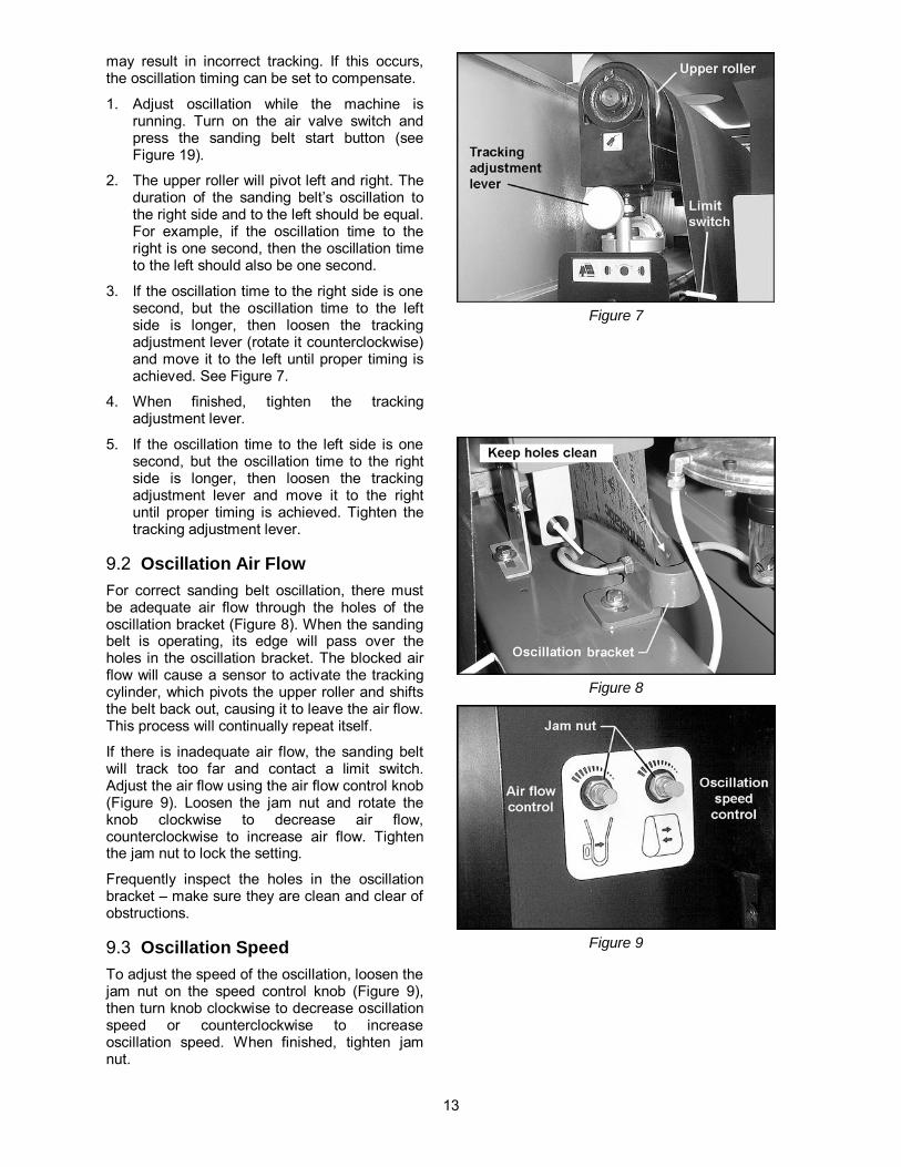
may result in incorrect tracking. If this occurs, the oscillation timing can be set to compensate.
1. Adjust oscillation while the machine is running. Turn on the air valve switch and press the sanding belt start button (see Figure 19).
2. The upper roller will pivot left and right. The duration of the sanding belt’s oscillation to the right side and to the left should be equal. For example, if the oscillation time to the right is one second, then the oscillation time to the left should also be one second.
3. If the oscillation time to the right side is one second, but the oscillation time to the left side is longer, then loosen the tracking adjustment lever (rotate it counterclockwise) and move it to the left until proper timing is achieved. See Figure 7.
4. When finished, tighten the tracking adjustment lever.
5. If the oscillation time to the left side is one second, but the oscillation time to the right side is longer, then loosen the tracking adjustment lever and move it to the right until proper timing is achieved. Tighten the tracking adjustment lever.
9.2 Oscillation Air Flow For correct sanding belt oscillation, there must be adequate air flow through the holes of the oscillation bracket (Figure 8). When the sanding belt is operating, its edge will pass over the holes in the oscillation bracket. The blocked air flow will cause a sensor to activate the tracking cylinder, which pivots the upper roller and shifts the belt back out, causing it to leave the air flow. This process will continually repeat itself.
If there is inadequate air flow, the sanding belt will track too far and contact a limit switch. Adjust the air flow using the air flow control knob (Figure 9). Loosen the jam nut and rotate the knob clockwise to decrease air flow, counterclockwise to increase air flow. Tighten the jam nut to lock the setting.
Frequently inspect the holes in the oscillation bracket – make sure they are clean and clear of obstructions.
9.3 Oscillation Speed To adjust the speed of the oscillation, loosen the jam nut on the speed control knob (Figure 9), then turn knob clockwise to decrease oscillation speed or counterclockwise to increase oscillation speed. When finished, tighten jam nut.
Figure 7
Figure 8
Figure 9

14
9.4 Platen Position The sander has a removable platen with a graphite strip and a felt pad to reduce friction against the sanding belt. Positioning of the platen depends upon the type of wood being used.
The height of the platen is set at the factory, but can be re-adjusted by rotating the platen adjustment knob (Figure 10). Each mark on the scale indicates a raising or lowering measurement of 0.005mm. One complete rotation of the scale moves the platen 0.2mm or approximately 8/1000 of an inch.
Theoretically, optimum finish sanding results are obtained when the bottom of the platen extends slightly below the bottom of the conveyor rollers. The main consideration in adjusting the platen is to make sure that both ends are symmetrical and level.
NOTE: The platen must be kept clean. After sanding, if the workpiece has straight notches across it, the graphite and felt pad have worn out and should be replaced immediately.
9.5 Replacing Graphite and Felt Pad To replace the graphite strip and felt pad, proceed as follows:
1. Remove the lock screw (B, Figure 3) and the spacer block (C, Figure 3).
2. Place the platen pull hook into the hole on the end of the platen and pull out the lower portion of the platen assembly, as shown in Figure 10. NOTE: The platen is tightly fitted and will require a firm pull with the pull hook.
3. Note carefully how the current graphite and felt strip are mounted. Replace them with the new ones.
4. Re-install the platen by aligning the end of it with the dovetail track on the fixed portion of the platen assembly, and push it all the way in using the pull hook.
5. Replace the spacer block and lock screw.
9.6 V-Belt Tension and Replacement For the first few days of operation a new belt should be checked occasionally and adjusted for tension as necessary until the belt is properly “worn in.”
The v-belts on the main motor and table elevating motor should be checked for proper tension.
Tighten any of the v-belts as follows:
Figure 10
Figure 11
Figure 12

15
1. Disconnect sander from power source.
2. Loosen the lower hex nut (A, Figure 11/12) on the motor base.
3. Tighten the top hex nut (B, Figure 11/12) to lower the motor plate until proper tension is achieved.
4. When the belt is properly tensioned, you should be able to push in the belt approximately 3/4” at a point midway between the pulleys using moderate finger pressure.
5. Re-tighten the bottom hex nut (B, Figure 11/12) against the bottom of the motor plate.
If installing a new v-belt, use the hex nuts to raise the motor plate enough to remove the old belt and mount the new one.
NOTE: When replacing v-belts on the main motor, replace the entire set of three simultaneously.
9.7 Conveyor Belt Tension Check the tension of the conveyor belt on the infeed and outfeed rollers – the conveyor belt should be tight enough that you cannot shift it with your hands. If the conveyor belt needs tightening, proceed as follows.
1. Disconnect sander from power source.
2. Rotate the adjustment screws (the left one is shown in Figure 13) as needed with a 19mm wrench. Rotate clockwise to increase tension, counter-clockwise to decrease tension. (NOTE: Removal of the emergency stop cover is not necessary for tensioning.)
NOTE: Do not over-tighten the screws as this will hasten wear of the conveyor belt.
9.8 Conveyor Belt Tracking The conveyor belt should remain centered upon the rollers during operation. If it approaches to either the left or right side, adjustment is necessary.
First check that the conveyor belt tension is correct. If the tension needs adjustment, do this first before you adjust the tracking (see “Conveyor Belt Tension”). Then proceed as follows.
Conveyor belt tracking should be adjusted while the conveyor belt is running. Make adjustments in increments and allow the conveyor belt time to respond to each change.
Keep hands away from the moving conveyor belt.
Figure 13

16
1. Remove the four screws securing the emergency stop cover and remove the cover. See Figure 13. This will allow better inspection of the belt’s movement on the roller.
2. Turn on the conveyor belt.
3. Adjust tracking using the same adjustment screws that were used for tensioning in Figure 13.
4. If the conveyor belt is moving to the right side, turn the right screw clockwise. This will return the tracking toward the left.
5. If the conveyor belt is moving to the left side, turn the left screw clockwise. This will return the tracking toward the right.
6. A positioning wheel (Figure 14) has been provided on the right and left sides of the conveyor belt to limit the belt tracking. When adjusting the tracking, the conveyor belt should be moved until its edge just touches the positioning wheels.
7. Allow the sander to run for several minutes while observing the conveyor belt tracking and readjust if necessary.
8. Turn off the conveyor belt and re-install emergency stop cover.
9.9 Feed Rate The feed rate is infinitely variable within the provided range, in order to meet the sanding requirements of a wide variety of materials. Selecting a proper feed rate is largely a matter of experience. In general, soft woods require a higher feed rate, while hard woods require a lower feed rate.
Change the feed rate only while the conveyor belt is running. Failure to comply may cause damage to the gearbox.
Adjust the feed rate with the selector knob on the worm gear reducer (Figure 15). Turn the selector knob clockwise to decrease the conveyor belt speed, counterclockwise to increase it.
9.10 Pressure Bar Adjustment The front and rear sets of pressure bars have been factory adjusted. This setting should, however, be checked before operating the sander.
The pressure bars should be parallel to the conveyor table with equal pressure on each end, and are set slightly below the level of the sanding belt.
Figure 14
Figure 15

17
If the ends of the workpiece are sniped, the front pressure bars are too low. The pressure should be enough to firmly hold the workpiece against the conveyor, but not so hard that the ends of the workpiece spring up after clearing the bar.
Also, if the ends of the bars are not exerting equal pressure, the workpiece will tend to move sideways on the conveyor during sanding.
To raise or lower each set of pressure bars:
1. Disconnect sander from power source.
2. The sanding belt should be installed, and the air valve turned ON.
3. Place a sanded panel with even thickness on the conveyor table and under the pressure bars. The panel should be long enough to contact both front and back sets of pressure bars.
4. Raise the table manually using the handwheel (Figure 16) until the panel contacts the pressure bars.
5. Make sure the pressure at the right and left side of pressure bars is even.
6. If adjustment is needed, release the lock nut (A, Figure 17) with a 14mm wrench.
7. Insert the adjusting tool (B, Figure 17) into a hole in the adjusting knob. Rotate the adjusting knob clockwise to raise that side of the pressure bar, counterclockwise to lower it.
8. When finished, re-tighten lock nut (A, Figure 17).
9.11 Table Parallelism Parallelism of the conveyor table to the contact roller has been factory-set and should not require further adjustment. However, as the machine receives extended use, this setting should be checked.
Inspect parallelism by one of two methods:
1. Use a sanded board of equal thickness. Pass the board several times through the machine at a sanding depth of approximately 1/64”, then measure the thickness of the board at different points along the edges with calipers. If excessive variation occurs, the table needs adjusting.
OR, remove the sanding belt and place a gauge of some kind at one side of the conveyor table and below the contact roller. Raise the table manually using the handwheel until the gauge just touches the contact roller. Repeat at the other side of the table and compare the gauge readings.
Figure 16
Figure 17

18
If the readings are different, the table needs adjusting.
2. Disconnect sander from power source.
3. At the area of the table that needs adjustment, loosen the two screws (A, Figure 18) on the bracket of the elevation screw, and rotate the bracket as needed. (The elevation screw is protected by the dust guard bellow.) Turn the elevating screw clockwise to lower the table in that area, counterclockwise to raise the table (see Figure 18).
IMPORTANT: Turn both elevating screws at one side of the table an equal amount, in order to maintain front-to-back parallelism with the rollers.
4. Tighten screws (A, Figure 18).
5. Re-connect sander to power, and make further test runs. Make additional adjustments as needed, with the machine disconnected from power.
10.0 Operating Controls Figure 19 shows the control panel functions.
The emergency stop button shuts down all machine operations. The button remains engaged after being pushed. To disengage, rotate the ring until the emergency stop button pops back out.
The emergency stop cover has a plate (shown in Figure 16) which shuts down all machine operations when it is pushed.
10.1 Amperage Meter The amperage meter (Figure 19) continually monitors the load upon the sander. To avoid tripping of the circuit breaker and the overload relays, reduce the load immediately when the amperage meter indicates excessive amperage pull.
10.2 LED Controller and Keypad The controller is used for precise positioning of the conveyor table based upon the workpiece thickness and your desired sanding depth.
Figure 20 shows the key features of the unit.
The LED control unit comes pre-programmed from the factory. Do NOT alter the specifications of your control unit without authorization from WMH Tool Group. Incorrect programming of the device could cause unit failure as well as risk of injury to people and damage to the sander.
Figure 18
Figure 19
Figure 20

19
10.2.1 Calibration To establish the distance between conveyor table and sanding belt, proceed as follows:
1. Connect power and air to the sander, and turn the air valve switch on to tighten the sanding belt. NOTE: The controller will not move the table if the air valve switch is off.
2. Press and hold the UP button on the keypad to raise the conveyor table until the thicknesser knob (Figure 21) contacts the limit switch. The table will automatically stop while making slight contact with the sanding belt.
3. Press “0” (zero) on the keypad (the display will begin flashing and the input light will be lit). Then press SET for 2 to 3 seconds. The display will now read zero. This is the distance between sanding belt and conveyor table, upon which further movement of the table can be based.
4. Input a number using the keypad (display will begin flashing and the input light will be illuminated).
5. While the display is still flashing, press the START button on the keypad (run light will now be illuminated). The conveyor table will move to the desired distance from the sanding belt.
10.2.2 Using the LED for Operations The sander has a thicknesser which automatically sets the table at the thickness of your workpiece:
1. Place your workpiece upon the conveyor table and move it below the thicknesser, as shown in Figure 21. Keep the workpiece flat upon the table. Press and hold the UP button on the keypad to raise the conveyor table. When the workpiece contacts the limit switch the conveyor table will stop. The table is now positioned at the thickness of your workpiece.
2. Remove the workpiece.
3. Press and release the UP button, which will raise the table for the first sanding pass. NOTE: The arrow buttons are programmed to move the table in .005” increments.
10.2.3 Inch/Metric Toggle At any time you may switch between standard and metric measurements by pressing and holding SET for ten seconds.
Figure 21
4. Press the sanding belt START button and the conveyor table START button on the control panel, and feed the workpiece through the machine.
5. Make further passes as needed, raising the table each time using the UP button.
11.0 Operation Before operating the sander, make sure that:
1. The dust collection system is turned on. 2. Sanding belt tracking and oscillation are
working properly. 3. Conveyor belt tracking is correct. 4. All screws and handles are tightened
securely. 5. Working air pressure is correct. (Normal
working pressure is 75 to 80 PSI.) Do not operate sander until normal pressure is reached.
6. Thickness is correctly input into the LED unit.
7. Feed rate is correctly set. 8. Workpiece is free of nails, knots and other
obstructions.
11.1 Braking System The sander will not start or will halt operations if any of the following occur:
• No air supply to the machine. • No sanding belt installed. • Improper belt tension. • Sanding belt runs out of track. • The emergency stop button on the control
panel is pressed. • The emergency stop plate on the conveyor
table is pushed.

20
If the sanding belt breaks, all movement will be stopped, though the conveyor table can still be raised or lowered.
Once the machine has stopped, the operator should find where the braking system was tripped, and make the necessary adjustments. The machine can then be re-set and started.
12.0 Maintenance Before doing any
maintenance on the sander, disconnect it from the electrical supply by pulling out the plug or switching off the main switch. Failure to comply may cause serious injury.
The interior of the machine should be thoroughly cleaned each day after using the sander. Remove the sanding belt before cleaning and re-install it when finished.
Keep the sanding belt clean using cleaning sticks or pads (not provided).
Blow dust off the conveyor belt with compressed air or use a dust collector vacuum attachment.
The bearings should be greased after every 150 work hours.
The water should be removed daily from inside the filter cups. On the filter/regulator at the back of the cabinet, press the drain cock (see Figure 2). On the filter inside the cabinet, unscrew the cup to empty it.
The oil inside the gear reducer should be replaced after the first 100 work hours and every 2500 work hours thereafter. Recommended oil is #90 gear oil. Pour oil into the filler hole until the level is above the dot on the sight glass. See Figure 22.
Figure 22
13.0 Dust Port Layout

21
14.0 Troubleshooting the Sander
Trouble Probable Cause Remedy
Sander will not start. No incoming power. Check that sander is connected to power, fuses are not blown or circuit breakers are not tripped.
Low voltage. Check voltage at power source.
Loose wiring. Inspect and remedy any loose connections on sander.
Starting switch is defective. Replace switch.
Motor is defective. Replace motor.
Sanding belt clogs too quickly.
Grit of sanding belt is too fine. Choose a larger grit of sanding paper.
Too much material being sanded off. Reduce the amount of material being removed.
Wood is too oily. Choose different stock.
Too much dirt or glue on the wood. Choose cleaner stock.
Wood is too moist. Allow wood to dry before sanding.
Sanding belt will not run, or slips on the rollers.
Air valve switch is Off. Turn on air valve.
Emergency stop button is engaged. Disengage the stop button.
Limit switches are activated. Position sanding belt so it is between the limit switches.
Insufficient air pressure causing belt to slip on rollers.
Make sure air pressure regulator is set at 75 to 80 PSI (page 9).
Dust or debris on conveyor rollers Clean conveyor rollers.
Sanding belt keeps triggering the limit switches.
Tracking adjustment/oscillation is not correct.
Set tracking correctly. See page 12 and 13.
Air flow control is closed. Open air flow control (page 13).
Sensors are blocked on the air cylinder bracket.
Clean the sensor areas on the cylinder bracket. See page 13.
Machine takes too long to stop after emergency switch is activated.
Air pressure is too low. Set air pressure to 75 to 80 PSI.
Brake pads are worn. Replace brake pads.
Grinding noise when brake is activated.
Brake pads are worn. Replace brake pads (rotor may need turning also).
Too much rounding occurs along edges when solid wood is sanded.
Too much material is being removed, making the contact drum press too tightly.
Reduce the amount of material being removed.
The front end of stock is thinner than the rear.
Rear pressure bar is too low in relation to the contact drum.
Raise rear pressure bar (page 16-17).

22
Trouble Probable Cause Remedy
The rear end of stock is thinner than the front.
Front pressure bar is too low in relation to the contact drum.
Raise front pressure bar (page 16).
Uneven thickness between the left and right sides of the workpiece.
Table not positioned correctly in relation to contact drum.
Adjust table until it is parallel left to right (pages 17-18).
Front pressure bar not in correct position in relation to contact drum.
Adjust front pressure bar to parallel. See page 16.
Graphite strip and felt pad are worn out.
Replace graphite strip and felt pad. See page 14.
Conveyor belt is worn. Replace conveyor belt (contact Powermatic Technical Service).
Uneven thickness between the front and rear ends of the workpiece.
Feed rate is too high. Reduce feed rate. See page 16.
Too much stock removal. Reduce amount of material being removed.
Grit of sanding belt too fine. Use larger grit sanding belt.
Unequal position of pressure bars. Adjust pressure bars to produce equal pressure on stock.
Table not parallel front to back. Adjust table until it is parallel front to back (pages 17-18).
Workpiece slips on conveyor belt.
Not enough pressure between pressure bar and workpiece.
Increase pressure between pressure bar and workpiece.
Too much dust or debris on conveyor belt.
Clean conveyor belt with compressed air.
Rear pressure bar too low, halts the workpiece.
Raise rear pressure bar until proper contact is achieved.
Straight strip of notches or grooves in the workpiece.
Dirty pressure bar. Clean pressure bar.
Contact drum is scratched. Replace contact drum.
Graphite strip and felt pad are worn. Replace graphite and pad.
“Snake” marks on workpiece.
Local damage to the sanding belt. Replace sanding belt.
Straight parallel running stripes over entire width of workpiece.
Joint of the sanding belt is too thick or is open.
Repair joint or replace sanding belt.
Glossy spots on the wood.
Sanding belt is too old. Replace with new sanding belt.
Rear pressure bar is too low. Raise rear pressure bar.

23
15.0 Troubleshooting the LED Unit Trouble Probable Cause Remedy
The display fails to show figures.
Fuse is burned out. Replace 1A fuse.
Control unit is malfunctioning. Unit must be repaired or replaced by authorized service personnel.
Display shows abnormal figures.
Wrong figures were input. Input the proper numbers in accordance with the actual dimensions.
If the above step is ineffective, turn the power off and then on. If the display is still not working properly, it should be repaired or replaced. Contact Powermatic Technical Service.
Display shows figures, but they do not change in conjunction with the hoist motor’s operation.
Proximity switch is not functioning. Have proximity switch replaced by authorized service personnel.
Distance between induction unit and induction sheet is more than 1mm.
Adjust distance between induction unit and induction sheet to less than 1mm.
Encoder not running in accordance with the table movement.
Encoder should be repaired or replaced by a service representative.
Travel dimension incorrect.
Distance between sanding roller and conveyor belt has not been input correctly into the unit.
Correct control unit parameter. See page 19.
Table will not respond to figures input into unit.
Air valve turned off, sanding belt not tensioned.
Turn air valve on.
16.0 Replacement Parts Replacement parts are listed on the following pages. To order parts or reach our service department, call 1-800-274-6848, Monday through Friday (see our website for business hours, www.powermatic.com). Having the Model Number and Serial Number of your machine available when you call will allow us to serve you quickly and accurately.

24
16.1.1 Base and Motor Assembly – Model WB-25 ONLY Parts list on page 25.

25
16.1.2 Parts List: Base and Motor Assembly – Model WB-25 Exploded view on page 24.
Index No. Part No. Description Size Qty 1 ............... WB25-201 ................Machine Base........................................................................................ 1 2 ............... WB25-202 ................Motor Plate ............................................................................................ 1 3 ............... WB25-203 ................Rod ....................................................................................................... 1 4 ............... WB25-149 ................Hex Nut ..............................................................1/2-12 ......................... 3 5 ............... WB25-205 ................Motor Adjusting Screw ........................................................................... 1 6 ............... TS-0720111 .............Lock Washer ......................................................1/2 .............................. 1 7 ............... TS-0060061 .............Hex Cap Screw ..................................................3/8-16x1-1/4 ............... 4 8 ............... TS-0680061 .............Flat Washer ........................................................1/2 .............................. 2 9 ............... WB25-209 ................Motor ..................................................................15HP, 230/460V, 3Ph . 1 10 ............. WB25-210 ................Motor Pulley .......................................................................................... 1 11 ............. TS-0208071 .............Socket Head Cap Screw .....................................5/16-18x1-1/4 ............. 3 12 ............. WB25-212 ................Leveling Nut .......................................................................................... 4 13 ............. WB25-213 ................Key.....................................................................8x10x74 ..................... 1 14 ............. TS-0051051 .............Hex Cap Screw ..................................................5/16-18x1 ................... 4 15 ............. TS-0720081 .............Lock Washer ......................................................5/16 ............................ 4 16 ............. WB25-216 ................Disc Brake ............................................................................................. 1 17 ............. WB25-217 ................Pulley Bushing....................................................................................... 1 18 ............. VB-B73 ....................V-Belt .................................................................B-73 ........................... 2 19 ............. WB25-219 ................Brake Base ............................................................................................ 1 20 ............. TS-0680041 .............Flat Washer ........................................................3/8 .............................. 2 21 ............. TS-0060031 .............Hex Cap Screw ..................................................3/8-16x3/4 .................. 2 22 ............. 6294280...................Limit Switch ........................................................................................... 2 23 ............. 6294281...................Limit Switch Plate .................................................................................. 2 24 ............. TS-0050021 .............Hex Cap Screw ..................................................1/4-20x5/8 .................. 2 25 ............. TS-0680021 .............Flat Washer ........................................................1/4 .............................. 2 26 ............. TS-0270071 .............Set Screw ...........................................................5/16-18x3/4 ................ 4 27 ............. WB25-227 ................Bushing ................................................................................................. 2 28 ............. WB25-131 ................Flat Head Screw .................................................M5x8 .......................... 4 29 ............. TS-0720071 .............Lock Washer ......................................................1/4 .............................. 2 30 ............. WB25-230 ................Brake Housing ....................................................................................... 1 31 ............. WB25-231 ................Front Cover ........................................................................................... 1 32 ............. WB25-232 ................Brake Lining .......................................................................................... 1 33 ............. WB25-233 ................Brake Lining .......................................................................................... 1 34 ............. WB25-234 ................Bushing ................................................................................................. 1 35 ............. WB25-235 ................Spring.................................................................................................... 1 36 ............. WB25-236 ................Inner Plate ............................................................................................. 1 37 ............. TS-1514041 .............Flat Head Socket Screw .....................................M6x25 ........................ 1 38 ............. WB25-238 ................Pin......................................................................................................... 2 39 ............. TS-1502051 .............Socket Head Cap Screw .....................................M5x20 ........................ 6 40 ............. TS-0720091 .............Lock Washer ......................................................3/8 .............................. 7 41 ............. TS-0561031 .............Hex Nut ..............................................................3/8-16 ......................... 2 42 ............. TS-1503031 .............Socket Head Cap Screw .....................................M6x12 ........................ 1 43 ............. WB25-243 ................Gasket................................................................................................... 1 44 ............. WB25-244 ................Leveling Screw ...................................................................................... 4

26
16.2.1 Base and Motor Assembly – Model WB-37 ONLY Parts list on page 27.

27
16.2.2 Parts List: Base and Motor Assembly – Model WB-37 Exploded view on page 26.
Index No. Part No. Description Size Qty 1 ............... WB37-201 ................Machine Base........................................................................................ 1 2 ............... WB37-202 ................Motor Plate ............................................................................................ 1 3 ............... WB37-203 ................Rod ....................................................................................................... 1 4 ............... WB25-149 ................Hex Nut ..............................................................1/2-12 ......................... 4 5 ............... WB37-205 ................Motor Adjusting Screw ........................................................................... 1 6 ............... TS-0720111 .............Lock Washer ......................................................1/2 .............................. 6 7 ............... WB25-701 ................Hex Cap Screw ..................................................1/2-12x1-1/2 ............... 4 8 ............... TS-0680061 .............Flat Washer ........................................................1/2 .............................. 2 9 ............... WB37-209 ................Motor ..................................................................20HP, 230/460V, 3Ph . 1 10 ............. WB37-210 ................Motor Pulley .......................................................................................... 1 11 ............. TS-0208071 .............Socket Head Cap Screw .....................................5/16-18x1-1/4 ............. 3 12 ............. WB25-212 ................Leveling Nut .......................................................................................... 4 13 ............. WB37-213 ................Key.....................................................................8x12x105 ................... 1 14 ............. TS-0051051 .............Hex Cap Screw ..................................................5/16-18x1 ................... 4 15 ............. TS-0720081 .............Lock Washer ......................................................5/16 ............................ 4 16 ............. WB25-216 ................Disc Brake ............................................................................................. 1 17 ............. WB37-217 ................Pulley Bushing....................................................................................... 1 18 ............. VB-B73 ....................V-Belt .................................................................B-73 ........................... 3 19 ............. WB37-219 ................Brake Base ............................................................................................ 1 20 ............. TS-0680041 .............Flat Washer ........................................................3/8 .............................. 2 21 ............. TS-0060031 .............Hex Cap Screw ..................................................3/8-16x3/4 .................. 2 22 ............. 6294280...................Limit Switch ........................................................................................... 2 23 ............. 6294281...................Limit Switch Plate .................................................................................. 2 24 ............. TS-0050021 .............Hex Cap Screw ..................................................1/4-20x5/8 .................. 2 25 ............. TS-0680021 .............Flat Washer ........................................................1/4 .............................. 2 26 ............. WB25-131 ................Flat Head Screw .................................................M5x8 .......................... 4 27 ............. TS-0720071 .............Lock Washer ......................................................1/4 .............................. 2 28 ............. 6294284...................Brake Housing ....................................................................................... 1 29 ............. 6294285...................Front Cover ........................................................................................... 1 30 ............. 6294286...................Brake Lining .......................................................................................... 1 31 ............. 6294661...................Rear Brake Lining .................................................................................. 1 32 ............. 6294287...................Bushing ................................................................................................. 1 33 ............. 6294288...................Spring.................................................................................................... 1 34 ............. 6294289...................Inner Plate ............................................................................................. 1 35 ............. TS-081F031 .............Flat Head Screw .................................................1/4-20x1/2 .................. 1 36 ............. 6294291...................Pin......................................................................................................... 2 37 ............. TS-0206041 .............Socket Head Cap Screw .....................................10-24x3/4 ................... 8 38 ............. TS-0720091 .............Lock Washer ......................................................3/8 .............................. 3 39 ............. TS-0561031 .............Hex Nut ..............................................................3/8-16 ......................... 2 40 ............. TS-0207031 .............Socket Head Cap Screw .....................................1/4-20x5/8 .................. 2 41 ............. 6294296...................Gasket................................................................................................... 1 42 ............. WB25-244 ................Leveling Screw ...................................................................................... 4

28
16.3.1 Base and Motor Assembly – Model WB-43 ONLY Parts list on page 29.

29
16.3.2 Parts List: Base and Motor Assembly – Model WB-43 Exploded view on page 28.
Index No. Part No. Description Size Qty 1 ............... WB43-201 ................Machine Base........................................................................................ 1 2 ............... WB43-202 ................Motor Plate ............................................................................................ 1 3 ............... WB43-203 ................Rod ....................................................................................................... 1 4 ............... WB25-149 ................Hex Nut ..............................................................1/2-12 ......................... 4 5 ............... 6294262...................Motor Adjusting Screw ........................................................................... 1 6 ............... TS-0720111 .............Lock Washer ......................................................1/2 .............................. 6 7 ............... WB25-701 ................Hex Cap Screw ..................................................1/2-12x1-1/2 ............... 4 8 ............... TS-0680061 .............Flat Washer ........................................................1/2 .............................. 2 9 ............... WB43-209 ................Motor ..................................................................25HP, 230/460V, 3Ph . 1 10 ............. WB43-210 ................Motor Pulley .......................................................................................... 1 11 ............. TS-0208071 .............Socket Head Cap Screw .....................................5/16-18x1-1/4 ............. 3 12 ............. WB25-212 ................Leveling Nut .......................................................................................... 4 13 ............. WB43-213 ................Key.....................................................................9×14×105 ................... 1 14 ............. TS-0051051 .............Hex Cap Screw ..................................................5/16-18x1 ................... 4 15 ............. TS-0720081 .............Lock Washer ......................................................5/16 ............................ 4 16 ............. WB25-216 ................Disc Brake ............................................................................................. 1 17 ............. WB43-217 ................Pulley Bushing....................................................................................... 1 18 ............. VB-B70 ....................V-Belt .................................................................B-70 ........................... 3 19 ............. WB37-219 ................Brake Base ............................................................................................ 1 20 ............. TS-0680041 .............Flat Washer ........................................................3/8 .............................. 2 21 ............. TS-0060031 .............Hex Cap Screw ..................................................3/8-16x3/4 .................. 2 22 ............. 6294280...................Limit Switch ........................................................................................... 2 23 ............. 6294281...................Limit Switch Plate .................................................................................. 2 24 ............. TS-0050021 .............Hex Cap Screw ..................................................1/4-20x5/8 .................. 2 25 ............. TS-0680021 .............Flat Washer ........................................................1/4 .............................. 2 26 ............. WB25-131 ................Flat Head Screw .................................................M5x8 .......................... 4 27 ............. TS-0720071 .............Lock Washer ......................................................1/4 .............................. 3 28 ............. WB43-228 ................Motor Cover .......................................................................................... 1 29 ............. TS-0207031 .............Socket Head Cap Screw .....................................1/4-20x5/8 .................. 2 30 ............. 6294284...................Brake Housing ....................................................................................... 1 31 ............. 6294285...................Front Cover ........................................................................................... 1 32 ............. 6294286...................Brake Lining .......................................................................................... 1 33 ............. 6294661...................Brake Lining .......................................................................................... 1 34 ............. 6294287...................Bushing ................................................................................................. 1 35 ............. 6294288...................Spring.................................................................................................... 1 36 ............. 6294289...................Inner Plate ............................................................................................. 1 37 ............. TS-081F031 .............Flat Head Screw .................................................1/4-20x1/2 .................. 1 38 ............. 6294291...................Pin......................................................................................................... 2 39 ............. TS-0206041 .............Socket Head Cap Screw .....................................10-24x3/4 ................... 8 40 ............. TS-0720091 .............Lock Washer ......................................................3/8 .............................. 3 41 ............. TS-0561031 .............Hex Nut ..............................................................3/8-16 ......................... 2 42 ............. TS-0207031 .............Socket Head Cap Screw .....................................1/4-20x5/8 .................. 2 43 ............. 6294296...................Gasket................................................................................................... 1 44 ............. WB25-244 ................Leveling Screw ...................................................................................... 4

30
16.4.1 Upper Cabinet Assembly – Model WB-25 ONLY Parts list on page 31.

31
16.4.2 Parts List: Upper Cabinet Assembly – Model WB-25 Exploded view on page 30.
Index No. Part No. Description Size Qty 1 ............... WB25-301 ................Upper Cabinet ....................................................................................... 1 2 ............... TS-1534032 .............Pan Head Screw ................................................M6x10 ........................ 7 3 ............... WB25-303 ................Upper Left Door ..................................................................................... 1 4 ............... WB25-304 ................Upper Right Door................................................................................... 1 5 ............... 6294509...................Door Lock .............................................................................................. 2 6 ............... TS-0208041 .............Socket Head Cap Screw .....................................5/16-18x3/4 ................ 4 7 ............... TS-0720081 .............Lock Washer ......................................................5/16 ............................ 5 8 ............... WB25-308 ................Lower Door ............................................................................................ 2 9 ............... TS-0561021 .............Hex Nut ..............................................................5/16-18 ....................... 1 10 ............. TS-081F031 .............Flat Head Screw .................................................1/4-20x1/2 .................. 8 11 ............. WB25-311 ................Emergency Plate ................................................................................... 1 12 ............. WB25-312 ................Door Hinge Pin ...................................................................................... 4 13 ............. TS-2361061 .............Lock Washer ......................................................M6 .............................. 6 14 ............. TS-1482021 .............Hex Cap Screw ..................................................M6x12 ........................ 4 15 ............. TS-0680031 .............Flat Washer ........................................................5/16 ............................ 5 16 ............. 6294280...................Limit Switch ........................................................................................... 1 17 ............. WB25-317 ................Limit Switch Holder ................................................................................ 1 18 ............. TS-1533032 .............Pan Head Screw ................................................M5x10 ........................ 1 19 ............. TS-0680021 .............Flat Washer ........................................................1/4 .............................. 3 20 ............. WB25-320 ................Fixed Bracket ........................................................................................ 1 21 ............. WB25-321 ................Thicknesser Post ................................................................................... 1 22 ............. TS-0207031 .............Socket Head Cap Screw .....................................1/4-20x5/8 .................. 2 23 ............. WB25-323 ................Cover .................................................................................................... 1

32
16.5.1 Upper Cabinet Assembly – Models WB-37, WB-43 Parts list on page 33.

33
16.5.2 Parts List: Upper Cabinet Assembly – Model WB-37 Exploded view on page 32.
Index No. Part No. Description Size Qty 1 ............... WB37-301 ................Upper Cabinet ....................................................................................... 1 2 ............... TS-1534032 .............Pan Head Screw ................................................M6x10 ........................ 8 3 ............... WB25-303 ................Upper Left Door ..................................................................................... 1 4 ............... WB25-304 ................Upper Right Door................................................................................... 1 5 ............... 6294509...................Door Lock .............................................................................................. 2 6 ............... TS-0208041 .............Socket Head Cap Screw .....................................5/16-18x3/4 ................ 4 7 ............... TS-0720081 .............Lock Washer ......................................................5/16 ............................ 5 8 ............... WB25-308 ................Lower Door ............................................................................................ 2 9 ............... TS-0561021 .............Hex Nut ..............................................................5/16-18 ....................... 1 10 ............. TS-081F031 .............Flat Head Screw .................................................1/4-20x1/2 .................. 8 11 ............. WB37-311 ................Emergency Plate ................................................................................... 1 12 ............. WB25-312 ................Door Hinge Pin ...................................................................................... 4 13 ............. TS-2361061 .............Lock Washer ......................................................M6 .............................. 6 14 ............. TS-1482021 .............Hex Cap Screw ..................................................M6x12 ........................ 4 15 ............. TS-0680031 .............Flat Washer ........................................................5/16 ............................ 5 16 ............. 6294280...................Limit Switch ........................................................................................... 1 17 ............. WB25-317 ................Limit Switch Holder ................................................................................ 1 18 ............. TS-1533032 .............Pan Head Screw ................................................M5x10 ........................ 1 19 ............. TS-0680021 .............Flat Washer ........................................................1/4 .............................. 2 20 ............. WB25-320 ................Fixed Bracket ........................................................................................ 1 21 ............. WB25-321 ................Thicknesser Post ................................................................................... 1 22 ............. TS-0207031 .............Socket Head Cap Screw .....................................1/4-20x5/8 .................. 2 23 ............. WB25-323 ................Cover .................................................................................................... 1
16.5.3 Parts List: Upper Cabinet Assembly – Model WB-43 Exploded view on page 32.
Index No. Part No. Description Size Qty 1 ............... WB43-301 ................Upper Cabinet ....................................................................................... 1 2 ............... TS-1534032 .............Pan Head Screw ................................................M6x10 ........................ 8 3 ............... WB43-303 ................Upper Left Door ..................................................................................... 1 4 ............... WB43-304 ................Upper Right Door................................................................................... 1 5 ............... 6294509...................Door Lock .............................................................................................. 2 6 ............... TS-0208041 .............Socket Head Cap Screw .....................................5/16-18x3/4 ................ 4 7 ............... TS-0720081 .............Lock Washer ......................................................5/16 ............................ 5 8 ............... WB43-308 ................Lower Door ............................................................................................ 2 9 ............... TS-0561021 .............Hex Nut ..............................................................5/16-18 ....................... 1 10 ............. TS-081F031 .............Flat Head Screw .................................................1/4-20x1/2 .................. 8 11 ............. WB43-311 ................Emergency Plate ................................................................................... 1 12 ............. WB25-312 ................Door Hinge Pin ...................................................................................... 4 13 ............. TS-2361061 .............Lock Washer ......................................................M6 .............................. 6 14 ............. TS-1482021 .............Hex Cap Screw ..................................................M6x12 ........................ 4 15 ............. TS-0680031 .............Flat Washer ........................................................5/16 ............................ 5 16 ............. 6294280...................Limit Switch ........................................................................................... 1 17 ............. WB25-317 ................Limit Switch Holder ................................................................................ 1 18 ............. TS-1533032 .............Pan Head Screw ................................................M5x10 ........................ 1 19 ............. TS-0680021 .............Flat Washer ........................................................1/4 .............................. 2 20 ............. WB25-320 ................Fixed Bracket ........................................................................................ 1 21 ............. WB25-321 ................Thicknesser Post ................................................................................... 1 22 ............. TS-0207031 .............Hex Socket Cap Screw .......................................1/4-20x5/8 .................. 2 23 ............. WB25-323 ................Cover .................................................................................................... 1

34
16.6.1 Table Raising Assembly – Models WB-25, WB-37, WB-43 Parts list on page 35 (WB-25), page 36 (WB-37) and page 37 (WB-43).

35
16.6.2 Parts List: Table Raising Assembly – Model WB-25 Exploded view on page 34.
Index No. Part No. Description Size Qty 1 ............... 6294297...................Elevation Screw ..................................................................................... 4 2 ............... TS-0051051 .............Hex Cap Screw ..................................................5/16-18x1 ................... 8 3. .............. TS-0680031 .............Flat Washer ........................................................5/16 ............................ 8 4 ............... TS-0720081 .............Lock Washer ......................................................5/16 .......................... 20 5 ............... TS-0720091 .............Lock Washer ......................................................3/8 .............................. 4 6 ............... TS-0060051 .............Hex Cap Screw ..................................................3/8-16x1 ..................... 4 7 ............... 6294302...................Elevation Slide....................................................................................... 2 8 ............... 6294303...................Dust Guard Bellow ................................................................................. 4 9 ............... TS-0081031 .............Hex Cap Screw ..................................................5/16-18x3/4 .............. 12 10 ............. TS-0680041 .............Flat Washer ........................................................3/8 .............................. 6 11 ............. 6294305...................Chain .................................................................................................... 1 12 ............. 6294306...................Nut Housing .......................................................................................... 4 13 ............. 6294307...................Nut ........................................................................................................ 4 14 ............. 6294308...................Thrust Bearing ....................................................................................... 4 15 ............. 6294309...................C-Circlip ................................................................................................ 4 16 ............. 6294310...................Sprocket Wheel ..................................................................................... 4 17 ............. 6294311...................Elevation Gearbox ................................................................................. 1 18 ............. 6294312...................Worm Gear ............................................................................................ 1 19 ............. BB-6005Z ................Ball Bearing ........................................................6005Z ......................... 2 20 ............. 6294314...................Bearing Cap .......................................................................................... 1 21 ............. TS-0207041 .............Socket Head Cap Screw .....................................1/4-20x3/4 .................. 3 22 ............. 6294316...................Worm Gear ............................................................................................ 1 23 ............. BB-6002Z ................Ball Bearing ........................................................6002Z ......................... 2 24 ............. 6294318...................Bearing Cap .......................................................................................... 1 25 ............. TS-0206031 .............Socket Head Cap Screw .....................................10-24x5/8 ................... 3 26 ............. 6294320...................Bearing Cap .......................................................................................... 1 27 ............. TS-0207031 .............Socket Head Cap Screw .....................................1/4-20x5/8 .................. 3 28 ............. 6294322...................Sprocket Wheel ..................................................................................... 1 29 ............. TS-0270051 .............Set Screw ...........................................................5/16-18x1/2 ................ 2 30 ............. 6294324...................Pulley .................................................................................................... 1 31 ............. VB-A37 ....................V-Belt .................................................................A-37 ........................... 1 32 ............. 6294326...................Motor Pulley .......................................................................................... 1 33 ............. TS-0267051 .............Set Screw ...........................................................1/4-20x1/2 .................. 3 34 ............. TS-0561031 .............Hex Nut ..............................................................3/8-16 ......................... 1 35 ............. TS-0561021 .............Hex Nut ..............................................................5/16-18 ....................... 1 36 ............. 6294330...................Hand Wheel .......................................................................................... 1 37 ............. 6294331...................Motor Base ............................................................................................ 1 38 ............. TS-0050051 .............Hex Cap Screw ..................................................1/4-20×1 ..................... 4 39 ............. TS-0720071 .............Lock Washer ......................................................1/4 .............................. 5 40 ............. 6294333...................Motor Base Adjustment Rod .................................................................. 1 41 ............. TS-0680061 .............Flat Washer ........................................................1/2 .............................. 2 42 ............. WB25-149 ................Hex Nut ..............................................................1/2-12 ......................... 3 43 ............. TS-0720111 .............Lock Washer ......................................................1/2 .............................. 2 44 ............. TS-0680021 .............Flat Washer ........................................................1/4 .............................. 1 45 ............. 6294334...................Motor ..................................................................1/4HP, 230/460V, 3Ph 1 46 ............. TS-0561011 .............Hex Nut ..............................................................1/4-20 ......................... 4 47 ............. WB25-447 ................Hex Head Screw ................................................1/2-12x4 ..................... 1 48 ............. WB25-448 ................Switch Plate .......................................................................................... 1 49 ............. TS-0050011 .............Hex Cap Screw ..................................................1/4-20x1/2 .................. 1 50 ............. WB25-450 ................Switch ................................................................................................... 1 51 ............. TS-2283302 .............Pan Head Screw ................................................M3x30 ........................ 2 52 ............. TS-1540011 .............Hex Nut ..............................................................M3 .............................. 2 53 ............. 6294337...................Key.....................................................................5/16x5/16x3/4 ............. 1 54 ............. 6294338...................Key.....................................................................4x4x20 ....................... 1 55 ............. 6294339...................Key.....................................................................4x4x16 ....................... 1

36
56 ............. 6294340...................Sprocket Wheel Adjustment Piece ......................................................... 1 57 ............. 6294341...................Sprocket Wheel Shaft ............................................................................ 1 58 ............. BB-6003ZZ ..............Bearing...............................................................6003ZZ....................... 1 59 ............. 6294343...................Adjustment Sprocket Wheel ................................................................... 1 60 ............. 6294344...................Sprocket Wheel Adjustment Rod ........................................................... 1 16.6.3 Parts List: Table Raising Assembly – Model WB-37 Exploded view on page 34.
Index No. Part No. Description Size Qty 1 ............... 6294297...................Elevation Screw ..................................................................................... 4 2 ............... TS-0051051 .............Hex Cap Screw ..................................................5/16-18x1 ................... 8 3. .............. TS-0680031 .............Flat Washer ........................................................5/16 ............................ 8 4 ............... TS-0720081 .............Lock Washer ......................................................5/16 .......................... 20 5 ............... TS-0720091 .............Lock Washer ......................................................3/8 .............................. 4 6 ............... TS-0060051 .............Hex Cap Screw ..................................................3/8-16x1 ..................... 4 7 ............... 6294302...................Elevation Slide....................................................................................... 2 8 ............... 6294303...................Dust Guard Bellow ................................................................................. 4 9 ............... TS-0081031 .............Hex Cap Screw ..................................................5/16-18×3/4 .............. 12 10 ............. TS-0680041 .............Flat Washer ........................................................3/8 .............................. 6 11 ............. 6294305...................Chain .................................................................................................... 1 12 ............. 6294306...................Nut Housing .......................................................................................... 4 13 ............. 6294307...................Nut ........................................................................................................ 4 14 ............. 6294308...................Thrust Bearing ....................................................................................... 4 15 ............. 6294309...................C-Circlip ................................................................................................ 4 16 ............. 6294310...................Sprocket Wheel ..................................................................................... 4 17 ............. 6294311...................Elevation Gearbox ................................................................................. 1 18 ............. 6294312...................Worm Gear ............................................................................................ 1 19 ............. BB-6005Z ................Ball Bearing ........................................................6005Z ......................... 2 20 ............. 6294314...................Bearing Cap .......................................................................................... 1 21 ............. TS-0207041 .............Socket Head Cap Screw .....................................1/4-20x3/4 .................. 3 22 ............. 6294316...................Worm Gear ............................................................................................ 1 23 ............. BB-6002Z ................Ball Bearing ........................................................6002Z ......................... 2 24 ............. 6294318...................Bearing Cap .......................................................................................... 1 25 ............. TS-0206031 .............Socket Head Cap Screw .....................................10-24x5/8 ................... 3 26 ............. 6294320...................Bearing Cap .......................................................................................... 1 27 ............. TS-0207031 .............Socket Head Cap Screw .....................................1/4-20x5/8 .................. 3 28 ............. 6294322...................Sprocket Wheel ..................................................................................... 1 29 ............. TS-0270051 .............Set Screw ...........................................................5/16-18x1/2 ................ 2 30 ............. 6294324...................Pulley .................................................................................................... 1 31 ............. VB-A37 ....................V-Belt .................................................................A-37 ........................... 1 32 ............. 6294326...................Motor Pulley .......................................................................................... 1 33 ............. TS-0267051 .............Set Screw ...........................................................1/4-20x1/2 .................. 3 34 ............. TS-0561031 .............Hex Nut ..............................................................3/8-16 ......................... 1 35 ............. TS-0561021 .............Hex Nut ..............................................................5/16-18 ....................... 1 36 ............. 6294330...................Hand Wheel .......................................................................................... 1 37 ............. 6294331...................Motor Base ............................................................................................ 1 38 ............. TS-0050051 .............Hex Cap Screw ..................................................1/4-20x1 ..................... 4 39 ............. TS-0720071 .............Lock Washer ......................................................1/4 .............................. 5 40 ............. 6294333...................Motor Base Adjustment Rod .................................................................. 1 41 ............. TS-0680061 .............Flat Washer ........................................................1/2 .............................. 2 42 ............. WB25-149 ................Hex Nut ..............................................................1/2-12 ......................... 3 43 ............. TS-0720111 .............Lock Washer ......................................................1/2 .............................. 2 44 ............. TS-0680021 .............Flat Washer ........................................................1/4 .............................. 1 45 ............. 6294334...................Motor ..................................................................1/4HP, 230/460V, 3Ph 1 46 ............. TS-0561011 .............Hex Nut ..............................................................1/4-20 ......................... 4 47 ............. WB25-447 ................Hex Head Screw ................................................1/2-12x4 ..................... 1

37
48 ............. WB25-448 ................Switch Plate .......................................................................................... 1 49 ............. TS-0050011 .............Hex Cap Screw ..................................................1/4-20x1/2 .................. 1 50 ............. WB25-450 ................Switch ................................................................................................... 1 51 ............. TS-2283302 .............Screw .................................................................M3x30 ........................ 2 52 ............. TS-1540011 .............Hex Nut ..............................................................M3 .............................. 2 53 ............. 6294337...................Key.....................................................................5/16x5/16x3/4 ............. 1 54 ............. 6294338...................Key.....................................................................4x4x20 ....................... 1 55 ............. 6294339...................Key.....................................................................4x4x16 ....................... 1 56 ............. 6294340...................Sprocket Wheel Adjustment Piece ......................................................... 1 57 ............. 6294341...................Sprocket Wheel Shaft ............................................................................ 1 58 ............. BB-6003ZZ ..............Bearing...............................................................6003ZZ....................... 1 59 ............. 6294343...................Adjustment Sprocket Wheel ................................................................... 1 60 ............. 6294344...................Sprocket Wheel Adjustment Rod ........................................................... 1 16.6.4 Parts List: Table Raising Assembly – Model WB-43 Exploded view on page 34.
Index No. Part No. Description Size Qty 1 ............... 6294297...................Elevation Screw ..................................................................................... 4 2 ............... TS-0051051 .............Hex Cap Screw ..................................................5/16-18x1 ................... 8 3. .............. TS-0680031 .............Flat Washer ........................................................5/16 ............................ 8 4 ............... TS-0720081 .............Lock Washer ......................................................5/16 .......................... 20 5 ............... TS-0720091 .............Lock Washer ......................................................3/8 .............................. 4 6 ............... TS-0060051 .............Hex Cap Screw ..................................................3/8-16x1 ..................... 4 7 ............... 6294302...................Elevation Slide....................................................................................... 2 8 ............... 6294303...................Dust Guard Bellow ................................................................................. 4 9 ............... TS-0081031 .............Hex Cap Screw ..................................................5/16-18x3/4 .............. 12 10 ............. TS-0680041 .............Flat Washer ........................................................3/8 .............................. 6 11 ............. 6294305...................Chain .................................................................................................... 1 12 ............. 6294306...................Nut Housing .......................................................................................... 4 13 ............. 6294307...................Nut ........................................................................................................ 4 14 ............. 6294308...................Thrust Bearing ....................................................................................... 4 15 ............. 6294309...................C-Circlip ................................................................................................ 4 16 ............. 6294310...................Sprocket Wheel ..................................................................................... 4 17 ............. 6294311...................Elevation Gearbox ................................................................................. 1 18 ............. 6294312...................Worm Gear ............................................................................................ 1 19 ............. BB-6005Z ................Ball Bearing ........................................................6005Z ......................... 2 20 ............. 6294314...................Bearing Cap .......................................................................................... 1 21 ............. TS-0207041 .............Socket Head Cap Screw .....................................1/4-20x3/4 .................. 3 22 ............. 6294316...................Worm Gear ............................................................................................ 1 23 ............. BB-6002Z ................Ball Bearing ........................................................6002Z ......................... 2 24 ............. 6294318...................Bearing Cap .......................................................................................... 1 25 ............. TS-0206031 .............Socket Head Cap Screw .....................................10-24x5/8 ................... 3 26 ............. 6294320...................Bearing Cap .......................................................................................... 1 27 ............. TS-0207031 .............Socket Head Cap Screw .....................................1/4-20x5/8 .................. 3 28 ............. 6294322...................Sprocket Wheel ..................................................................................... 1 29 ............. TS-0270051 .............Set Screw ...........................................................5/16-18x1/2 ................ 2 30 ............. 6294324...................Pulley .................................................................................................... 1 31 ............. VB-A36 ....................V-Belt .................................................................A-36 ........................... 1 32 ............. 6294326...................Motor Pulley .......................................................................................... 1 33 ............. TS-0267051 .............Set Screw ...........................................................1/4-20x1/2 .................. 3 34 ............. TS-0561031 .............Hex Nut ..............................................................3/8-16 ......................... 1 35 ............. TS-0561021 .............Hex Nut ..............................................................5/16-18 ....................... 1 36 ............. 6294330...................Hand Wheel .......................................................................................... 1 37 ............. 6294331...................Motor Base ............................................................................................ 1 38 ............. TS-0050051 .............Hex Cap Screw ..................................................1/4-20x1 ..................... 4 39 ............. TS-0720071 .............Lock Washer ......................................................1/4 .............................. 5

38
40 ............. 6294333...................Motor Base Adjustment Rod .................................................................. 1 41 ............. TS-0680061 .............Flat Washer ........................................................1/2 .............................. 2 42 ............. WB25-149 ................Hex Nut ..............................................................1/2-12 ......................... 3 43 ............. TS-0720111 .............Lock Washer ......................................................1/2 .............................. 2 44 ............. TS-0680021 .............Flat Washer ........................................................1/4 .............................. 1 45 ............. 6294334...................Motor ..................................................................1/4HP, 230/460V, 3Ph 1 46 ............. TS-0561011 .............Hex Nut ..............................................................1/4-20 ......................... 4 47 ............. WB25-447 ................Hex Screw ..........................................................1/2-12x4 ..................... 1 48 ............. WB25-448 ................Switch Plate .......................................................................................... 1 49 ............. TS-0050011 .............Hex Cap Screw ..................................................1/4-20x1/2 .................. 1 50 ............. WB25-450 ................Switch ................................................................................................... 1 51 ............. TS-2283302 .............Pan Head Screw ................................................M3x30 ........................ 2 52 ............. TS-1540011 .............Hex Nut ..............................................................M3 .............................. 2 53 ............. 6294337...................Key.....................................................................5/16x5/16x3/4 ............. 1 54 ............. 6294338...................Key.....................................................................4x4x20 ....................... 1 55 ............. 6294339...................Key.....................................................................4x4x16 ....................... 1 56 ............. 6294340...................Sprocket Wheel Adjustment Piece ......................................................... 1 57 ............. 6294341...................Sprocket Wheel Shaft ............................................................................ 1 58 ............. BB-6003ZZ ..............Bearing...............................................................6003ZZ....................... 1 59 ............. 6294343...................Adjustment Sprocket Wheel ................................................................... 1 60 ............. 6294344...................Sprocket Wheel Adjustment Rod ........................................................... 1

39
16.7.1 Table and Conveyor Belt Assembly – Models WB-25, WB-37, WB-43 Parts list on page 40 (WB-25), page 41 (WB-37) and page 42 (WB-43).

40
16.7.2 Parts List: Table and Conveyor Belt Assembly – Model WB-25 Exploded view on page 39.
Index No. Part No. Description Size Qty 1 ............... WB25-501 ................Conveyor Table ..................................................................................... 1 2 ............... WB25-502 ................Conveyor Belt ........................................................................................ 1 3 ............... WB25-503 ................Mounting Bracket................................................................................... 1 4 ............... WB25-504 ................Washer.................................................................................................. 2 5 ............... TS-1550071 .............Flat Washer ........................................................M10 ............................ 4 6 ............... TS-1491031 .............Hex Cap Screw ..................................................M10x25 ...................... 2 7 ............... WB25-507 ................Outfeed Roller ....................................................................................... 1 8 ............... 6294352...................Bearing, Flange Mount .......................................................................... 1 9 ............... WB25-509 ................Reducer ................................................................................................ 1 10 ............. WB25-510 ................Plug ....................................................................................................... 1 11 ............. WB25-511 ................Cover .................................................................................................... 1 12 ............. 6290231...................Bearing, Flange Mount .......................................................................... 1 13 ............. TS-2361101 .............Lock Washer ......................................................M10 .......................... 10 14 ............. TS-0060061 .............Hex Cap Screw ..................................................3/8-16x1-1/4 ............... 2 15 ............. 6294356...................Bearing Cap .......................................................................................... 1 16 ............. WB25-516 ................Driven Pulley ......................................................................................... 1 17 ............. TS-0060071 .............Hex Cap Screw ..................................................3/8-16x1-1/2 ............... 6 18 ............. WB25-518 ................Driving Pulley ........................................................................................ 1 19 ............. WB25-519 ................Key.....................................................................8x8x55 ....................... 1 20 ............. TS-1490041 .............Hex Cap Screw ..................................................M8x25 ........................ 4 21 ............. TS-2361081 .............Lock Washer ......................................................M8 .............................. 8 22 ............. WB25-522 ................Motor ..................................................................1HP, 230/460V, 3Ph ... 1 23 ............. TS-1551071 .............Lock Washer ......................................................M10 ............................ 4 24 ............. WB25-524 ................Timing Belt ............................................................................................ 1 25 ............. TS-1505031 .............Socket Head Cap Screw .....................................M10x25 ...................... 4 26 ............. 6294383...................Variable Speed Unit Base Plate ............................................................. 1 27 ............. 6294387...................Variable Speed Unit Cover .................................................................... 1 28 ............. TS-1490031 .............Hex Cap Screw ..................................................M8x20 ........................ 1 29 ............. WB25-529 ................Infeed Roller Bracket, Right ................................................................... 1 30 ............. TS-0209031 .............Socket Head Cap Screw .....................................3/8-16x3/4 .................. 4 31 ............. WB25-531 ................Infeed Roller Bracket, Left ..................................................................... 1 32 ............. 6294372...................Conveyor Belt Position Wheel ................................................................ 2 33 ............. TS-0208101 .............Socket Head Cap Screw .....................................5/16-18x2 ................... 2 34 ............. TS-0720081 .............Lock Washer ......................................................5/16 ............................ 2 35 ............. TS-0561021 .............Hex Nut ..............................................................5/16-18 ....................... 2 36 ............. WB25-536 ................Emergency Stop Cover .......................................................................... 1 37 ............. TS-081F032 .............Pan Head Screw ................................................1/4-20x1/2 .................. 4 38 ............. 6294376...................Limit Switch ........................................................................................... 1 39 ............. TS-0810102 .............Round Head Screw ............................................10-24x1-3/4 ................ 2 ................. WB25-IRA ................Infeed Roller Assembly (Includes Index #40 thru #44) ............................ 1 40 ............. WB25-540 ................Adjustment Screw...............................................1/2-12x3 ..................... 2 41 ............. WB25-541 ................Infeed Roller Shaft ................................................................................. 1 42 ............. WB25-542 ................Infeed Roller .......................................................................................... 1 43 ............. BB-6206VV ..............Bearing...............................................................6206-2RS ................... 2 44 ............. 6294573...................C-Circlip ................................................................................................ 2 45 ............. 6294576...................Elevation Aluminum Limiter ................................................................... 1 46 ............. TS-0207081 .............Socket Head Cap Screw .....................................1/4-20x1-1/2 ............... 1 47 ............. WB25-547 ................Plug ....................................................................................................... 2
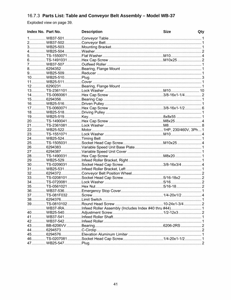
41
16.7.3 Parts List: Table and Conveyor Belt Assembly – Model WB-37 Exploded view on page 39.
Index No. Part No. Description Size Qty 1 ............... WB37-501 ................Conveyor Table ..................................................................................... 1 2 ............... WB37-502 ................Conveyor Belt ........................................................................................ 1 3 ............... WB25-503 ................Mounting Bracket................................................................................... 1 4 ............... WB25-504 ................Washer.................................................................................................. 2 5 ............... TS-1550071 .............Flat Washer ........................................................M10 ............................ 4 6 ............... TS-1491031 .............Hex Cap Screw ..................................................M10x25 ...................... 2 7 ............... WB37-507 ................Outfeed Roller ....................................................................................... 1 8 ............... 6294352...................Bearing, Flange Mount .......................................................................... 1 9 ............... WB25-509 ................Reducer ................................................................................................ 1 10 ............. WB25-510 ................Plug ....................................................................................................... 3 11 ............. WB25-511 ................Cover .................................................................................................... 1 12 ............. 6290231...................Bearing, Flange Mount .......................................................................... 1 13 ............. TS-2361101 .............Lock Washer ......................................................M10 .......................... 10 14 ............. TS-0060061 .............Hex Cap Screw ..................................................3/8-16x1-1/4 ............... 2 15 ............. 6294356...................Bearing Cap .......................................................................................... 1 16 ............. WB25-516 ................Driven Pulley ......................................................................................... 1 17 ............. TS-0060071 .............Hex Cap Screw ..................................................3/8-16x1-1/2 ............... 6 18 ............. WB25-518 ................Driving Pulley ........................................................................................ 1 19 ............. WB25-519 ................Key.....................................................................8x8x55 ....................... 1 20 ............. TS-1490041 .............Hex Cap Screw ..................................................M8x25 ........................ 4 21 ............. TS-2361081 .............Lock Washer ......................................................M8 .............................. 8 22 ............. WB25-522 ................Motor ..................................................................1HP, 230/460V, 3Ph ... 1 23 ............. TS-1551071 .............Lock Washer ......................................................M10 ............................ 4 24 ............. WB25-524 ................Timing Belt ............................................................................................ 1 25 ............. TS-1505031 .............Socket Head Cap Screw .....................................M10x25 ...................... 4 26 ............. 6294383...................Variable Speed Unit Base Plate ............................................................. 1 27 ............. 6294387...................Variable Speed Unit Cover .................................................................... 1 28 ............. TS-1490031 .............Hex Cap Screw ..................................................M8x20 ........................ 1 29 ............. WB25-529 ................Infeed Roller Bracket, Right ................................................................... 1 30 ............. TS-0209031 .............Socket Head Cap Screw .....................................3/8-16x3/4 .................. 4 31 ............. WB25-531 ................Infeed Roller Bracket, Left ..................................................................... 1 32 ............. 6294372...................Conveyor Belt Position Wheel ................................................................ 2 33 ............. TS-0208101 .............Socket Head Cap Screw .....................................5/16-18x2 ................... 2 34 ............. TS-0720081 .............Lock Washer ......................................................5/16 ............................ 2 35 ............. TS-0561021 .............Hex Nut ..............................................................5/16-18 ....................... 2 36 ............. WB37-536 ................Emergency Stop Cover .......................................................................... 1 37 ............. TS-081F032 .............Screw .................................................................1/4-20x1/2 .................. 4 38 ............. 6294376...................Limit Switch ........................................................................................... 1 39 ............. TS-0810102 .............Round Head Screw ............................................10-24x1-3/4 ................ 2 ................. WB37-IRA ................Infeed Roller Assembly (Includes Index #40 thru #44) ............................ 1 40 ............. WB25-540 ................Adjustment Screw...............................................1/2-12x3 ..................... 2 41 ............. WB37-541 ................Infeed Roller Shaft ................................................................................. 1 42 ............. WB37-542 ................Infeed Roller .......................................................................................... 1 43 ............. BB-6206VV ..............Bearing...............................................................6206-2RS ................... 2 44 ............. 6294573...................C-Circlip ................................................................................................ 2 45 ............. 6294576...................Elevation Aluminum Limiter ................................................................... 1 46 ............. TS-0207081 .............Socket Head Cap Screw .....................................1/4-20x1-1/2 ............... 1 47 ............. WB25-547 ................Plug ....................................................................................................... 2

42
16.7.4 Parts List: Table and Conveyor Belt Assembly – Model WB-43 Exploded view on page 39.
Index No. Part No. Description Size Qty 1 ............... WB43-501 ................Conveyor Table ..................................................................................... 1 2 ............... WB43-502 ................Conveyor Belt ........................................................................................ 1 3 ............... WB43-503 ................Mounting Bracket................................................................................... 1 4 ............... WB25-504 ................Washer.................................................................................................. 2 5 ............... TS-1550071 .............Flat Washer ........................................................M10 ............................ 4 6 ............... TS-1491031 .............Hex Cap Screw ..................................................M10x25 ...................... 2 7 ............... WB43-507 ................Outfeed Roller ....................................................................................... 1 8 ............... 6294352...................Bearing, Flange Mount .......................................................................... 1 9 ............... WB43-509 ................Reducer ................................................................................................ 1 10 ............. WB25-510 ................Plug ....................................................................................................... 3 11 ............. WB25-511 ................Cover .................................................................................................... 1 12 ............. 6290231...................Bearing, Flange Mount .......................................................................... 1 13 ............. TS-2361101 .............Lock Washer ......................................................M10 .......................... 10 14 ............. TS-0060061 .............Hex Cap Screw ..................................................3/8-16x1-1/4 ............... 2 15 ............. 6294356...................Bearing Cap .......................................................................................... 1 16 ............. 6294386...................Driven Pulley ......................................................................................... 1 17 ............. TS-0060071 .............Hex Cap Screw ..................................................3/8-16x1-1/2 ............... 6 18 ............. 6294385...................Driving Pulley ........................................................................................ 1 19 ............. WB25-519 ................Key.....................................................................8x8x55 ....................... 1 20 ............. TS-1490041 .............Hex Cap Screw ..................................................M8x25 ........................ 4 21 ............. TS-2361081 .............Lock Washer ......................................................M8 .............................. 8 22 ............. 6294363...................Motor ..................................................................2HP, 230/460V, 3Ph ... 1 23 ............. TS-1551071 .............Lock Washer ......................................................M10 ............................ 4 24 ............. WB25-524 ................Timing Belt ............................................................................................ 1 25 ............. TS-1505031 .............Socket Head Cap Screw .....................................M10x25 ...................... 4 26 ............. 6294383...................Variable Speed Unit Base Plate ............................................................. 1 27 ............. 6294387...................Variable Speed Unit Cover .................................................................... 1 28 ............. TS-1490031 .............Hex Cap Screw ..................................................M8x20 ........................ 1 29 ............. WB25-529 ................Infeed Roller Bracket, Right ................................................................... 1 30 ............. TS-0209031 .............Socket Head Cap Screw .....................................3/8-16x3/4 .................. 4 31 ............. WB25-531 ................Infeed Roller Bracket, Left ..................................................................... 1 32 ............. 6294372...................Conveyor Belt Position Wheel ................................................................ 2 33 ............. TS-0208101 .............Socket Head Cap Screw .....................................5/16-18x2 ................... 2 34 ............. TS-0720081 .............Lock Washer ......................................................5/16 ............................ 2 35 ............. TS-0561021 .............Hex Nut ..............................................................5/16-18 ....................... 2 36 ............. WB43-536 ................Emergency Stop Cover .......................................................................... 1 37 ............. TS-081F032 .............Pan Head Screw ................................................1/4-20x1/2 .................. 4 38 ............. 6294376...................Limit Switch ........................................................................................... 1 39 ............. TS-0810102 .............Round Head Screw ............................................10-24×1-3/4 ................ 2 ................. WB43-IRA ...............Infeed Roller Assembly (Includes Index #40 thru #44) ............................ 1 40 ............. WB25-540 ................Adjustment Screw...............................................1/2-12x3 ..................... 2 41 ............. 6294388...................Infeed Roller Shaft ................................................................................. 1 42 ............. WB43-542 ................Infeed Roller .......................................................................................... 1 43 ............. BB-6206VV ..............Bearing...............................................................6206-2RS ................... 2 44 ............. 6294573...................C-Circlip ................................................................................................ 2 45 ............. 6294576...................Elevation Aluminum Limiter ................................................................... 1 47 ............. WB25-547 ................Plug ....................................................................................................... 2

43
16.8.1 Pressure Bar Assembly – Models WB-25, WB-37, WB-43 Parts list on page 43 (WB-25) and page 44 (WB-37, WB-43).
16.8.2 Parts List: Pressure Bar Assembly – Model WB-25
Index No. Part No. Description Size Qty 1 ............... WB25-601 ................Roller Slider, Female ............................................................................. 2 2 ............... 6294391...................Roller Slider, Male ................................................................................. 2 3 ............... 6294392...................Front Roller Slider, Female .................................................................... 1 4 ............... 6294393...................Front Roller Slider, Male ........................................................................ 1 5 ............... 6294394...................Back Roller Slider, Female .................................................................... 1 6 ............... 6294395...................Back Roller Slider, Male ........................................................................ 1 7 ............... 6294396...................Roller Adjusting Screw ........................................................................... 4 8 ............... 6294397...................Spring Pin.............................................................................................. 4 9 ............... 6294398...................Spring.................................................................................................... 4 10 ............. 6294399...................Roller Slider Cover ................................................................................ 4 11 ............. TS-0207031 .............Socket Head Cap Screw .....................................1/4-20x5/8 .................. 8 12 ............. 6294401...................Roller Adjusting Knob ............................................................................ 4 13 ............. TS-0561031 .............Hex Nut ..............................................................3/8-16 ......................... 4 ................. WB25-PBA ..............Pressure Bar Assembly (Includes Index #14 thru #17) ........................... 1 14 ............. 6288605...................Pressure Bar Shaft ................................................................................ 4 15 ............. 6290278...................Pressure Bar Cover ............................................................................... 4 16 ............. BB-6001ZZ ..............Ball Bearing ........................................................6001ZZ....................... 8 17 ............. 6294405...................Bearing Cover ....................................................................................... 8 18 ............. TS-0267071 .............Set Screw ...........................................................1/4-20x3/4 .................. 8 19 ............. TS-0561011 .............Hex Nut ..............................................................1/4-20 ......................... 8 20 ............. TS-0720081 .............Lock Washer ......................................................5/16 ............................ 8 21 ............. TS-0051061 .............Hex Cap Screw ..................................................5/16-18x1-1/4 ............. 8

44
16.8.3 Parts List: Pressure Bar Assembly – Model WB-37 Exploded view on page 43.
Index No. Part No. Description Size Qty 1 ............... WB25-601 ................Roller Slider, Female ............................................................................. 2 2 ............... 6294391...................Roller Slider, Male ................................................................................. 2 3 ............... 6294392...................Front Roller Slider, Female .................................................................... 1 4 ............... 6294393...................Front Roller Slider, Male ........................................................................ 1 5 ............... 6294394...................Back Roller Slider, Female .................................................................... 1 6 ............... 6294395...................Back Roller Slider, Male ........................................................................ 1 7 ............... 6294396...................Roller Adjusting Screw ........................................................................... 4 8 ............... 6294397...................Spring Pin.............................................................................................. 4 9 ............... 6294398...................Spring.................................................................................................... 4 10 ............. 6294399...................Roller Slider Cover ................................................................................ 4 11 ............. TS-0207031 .............Socket Head Cap Screw .....................................1/4-20x5/8 .................. 8 12 ............. 6294401...................Roller Adjusting Knob ............................................................................ 4 13 ............. TS-0561031 .............Hex Nut ..............................................................3/8-16 ......................... 4 ................. WB37-PBA ..............Pressure Bar Assembly (Includes Index #14 thru #17) ........................... 1 14 ............. 6288705...................Pressure Bar Shaft ................................................................................ 4 15 ............. 6288723...................Pressure Bar Cover ............................................................................... 4 16 ............. BB-6001ZZ ..............Ball Bearing ........................................................6001ZZ....................... 8 17 ............. 6294405...................Bearing Cover ....................................................................................... 8 18 ............. TS-0267071 .............Set Screw ...........................................................1/4-20x3/4 .................. 8 19 ............. TS-0561011 .............Hex Nut ..............................................................1/4-20 ......................... 8 20 ............. TS-0720081 .............Lock Washer ......................................................5/16 ............................ 8 21 ............. TS-0051061 .............Hex Head Screw ................................................5/16-18x1-1/4 ............. 8 16.8.4 Parts List: Pressure Bar Assembly – Model WB-43 Exploded view on page 43.
Index No. Part No. Description Size Qty 1 ............... WB25-601 ................Roller Slider, Female ............................................................................. 2 2 ............... 6294391...................Roller Slider, Male ................................................................................. 2 3 ............... 6294392...................Front Roller Slider, Female .................................................................... 1 4 ............... 6294393...................Front Roller Slider, Male ........................................................................ 1 5 ............... 6294394...................Back Roller Slider, Female .................................................................... 1 6 ............... 6294395...................Back Roller Slider, Male ........................................................................ 1 7 ............... 6294396...................Roller Adjusting Screw ........................................................................... 4 8 ............... 6294397...................Spring Pin.............................................................................................. 4 9 ............... 6294398...................Spring.................................................................................................... 4 10 ............. 6294399...................Roller Slider Cover ................................................................................ 4 11 ............. TS-0207031 .............Socket Head Cap Screw .....................................1/4-20x5/8 .................. 8 12 ............. 6294401...................Roller Adjusting Knob ............................................................................ 4 13 ............. TS-0561031 .............Hex Nut ..............................................................3/8-16 ......................... 4 ................. WB43-PBA ..............Pressure Bar Assembly (Includes Index #14 thru #17) ........................... 1 14 ............. 6294402...................Pressure Bar Shaft ................................................................................ 4 15 ............. 6294403...................Pressure Bar Cover ............................................................................... 4 16 ............. BB-6001ZZ ..............Ball Bearing ........................................................6001ZZ....................... 8 17 ............. 6294405...................Bearing Cover ....................................................................................... 8 18 ............. TS-0267071 .............Set Screw ...........................................................1/4-20x3/4 .................. 8 19 ............. TS-0561011 .............Hex Nut ..............................................................1/4-20 ......................... 8 20 ............. TS-0720081 .............Lock Washer ......................................................5/16 ............................ 8 21 ............. TS-0051061 .............Hex Head Screw ................................................5/16-18x1-1/4 ............. 8

45
16.9.1 Platen Assembly – Model WB-25 only Parts list on page 45.
16.9.2 Parts List: Platen Assembly – Model WB-25 Index No. Part No. Description Size Qty 1 ............... WB25-701 ................Hex Cap Screw ..................................................1/2-12x1-1/2 ............... 4 2 ............... TS-0720111 .............Lock Washer ......................................................1/2 .............................. 4 3 ............... TS-0060061 .............Hex Cap Screw ..................................................3/8-16x1-1/4 ............... 3 4 ............... TS-0720091 .............Lock Washer ......................................................3/8 .............................. 3 5 ............... 6290291...................Diaphragm............................................................................................. 1 6 ............... 6290292...................Adjustment Knob ................................................................................... 1

46
Index No. Part No. Description Size Qty 7 ............... TS-0207041 .............Socket Head Cap Screw .....................................1/4-20x3/4 .................. 2 8 ............... 6290294...................Screw Rod............................................................................................. 1 9 ............... 6290295...................Platen Lock Lever .................................................................................. 1 10 ............. 6290296...................Scale Ring Base .................................................................................... 1 11 ............. 6290297...................Scale Ring Base Screw ......................................5/32x3/8 ..................... 2 12 ............. 6290298...................Scale Ring ............................................................................................. 1 13 ............. TS-0267051 .............Set Screw ...........................................................1/4-20x1/2 .................. 1 14 ............. 6290300...................Roller Pulley .......................................................................................... 1 15 ............. 6290301...................Key.....................................................................5/16x5/16x1-3/16 ........ 1 16 ............. TS-0208071 .............Socket Head Cap Screw .....................................5/16-18x1-1/4 ............. 3 17 ............. WB25-717 ................Seal Plate, Right .................................................................................... 1 18 ............. TS-081F032 .............Pan Head Screw ................................................1/4-20x1/2 .................. 4 19 ............. WB25-719 ................Seal Plate, Left. ..................................................................................... 1 20 ............. WB25-720 ................Bushing ................................................................................................. 1 21 ............. 6290310...................Bearing Base ......................................................................................... 1 22 ............. 6290311...................Bearing Frame....................................................................................... 1 23 ............. 6288623...................Free Roller ............................................................................................ 1 24 ............. 6288604...................Contact Roller........................................................................................ 1 25 ............. 6290312...................Oil Seal ................................................................................................. 4 26 ............. BB-6206...................Bearing...............................................................6206 ........................... 2 27 ............. 6290314...................Bearing Lock Nut ................................................................................... 2 28 ............. 6290315...................Bearing Cover ....................................................................................... 3 29 ............. TS-0207021 .............Socket Head Cap Screw .....................................1/4-20x1/2 ................ 12 30 ............. 6290317...................Grease Fitting ........................................................................................ 3 31 ............. 6290318...................Fastening Ring ...................................................................................... 1 32 ............. 6290321...................Bearing...............................................................22207 ......................... 1 33 ............. 6290322...................Bearing Cover ....................................................................................... 1 34 ............. 6290323...................Grease Fitting ........................................................................................ 1 35 ............. 6062032...................Bearing ..............................................................22206 ......................... 1 36 ............. 6290465...................Lock Nut .............................................................30mm (LH) ................. 1 37 ............. WB25-737 ................Mounting Frame .................................................................................... 1 38 ............. 6290325...................Graphite Base Gearbox, Left ................................................................. 1 39 ............. 6290326...................Graphite Base Gearbox, Right ............................................................... 1 40 ............. 6290327...................Gear Nut ............................................................................................... 2 41 ............. 6290328...................Platen Bar Adjusting Rod ....................................................................... 2 42 ............. 6290329...................Bushing ................................................................................................. 2 43 ............. 6290330...................Worm Gear Rod, Right .......................................................................... 1 44 ............. 6290331...................Worm Gear Rod Connector ................................................................... 1 45 ............. TS-0267051 .............Set Screw ...........................................................1/4-20x1/2 .................. 2 46 ............. TS-0561011 .............Hex Nut ..............................................................1/4-20 ......................... 2 47 ............. 6290334...................Worm Gear Rod, Left. ............................................................................ 1 48 ............. 6290335...................Sliding Platen, Male ............................................................................... 1 49 ............. TS-0060051 .............Hex Cap Screw ..................................................3/8-16x1 ..................... 4 50 ............. TS-0720091 .............Lock Washer ......................................................3/8 .............................. 7 51 ............. 6288601...................Sliding Platen, Female ........................................................................... 1 52 ............. 6288602...................Felt ........................................................................................................ 1 53 ............. 6288603...................Graphite ................................................................................................ 1 54 ............. 6290339...................Bar ........................................................................................................ 2 55 ............. 6294433...................Bar Screw.............................................................................................. 7 56 ............. 6290319...................Adaptor Assembly (includes #31 and 57) ............................................... 1 57 ............. 6290320...................Lock Nut ................................................................................................ 1 58 ............. WB25-758 ................Pulley Guard ......................................................................................... 1 59 ............. TS-081F032 .............Pan Head Screw ................................................1/4-20x1/2 .................. 2

47
16.10.1 Platen Assembly – Models WB-37, WB-43 Parts list on page 47 (WB-37) and page 48 (WB-43).
16.10.2 Parts List: Platen Assembly – Model WB-37 Index No. Part No. Description Size Qty 1 ............... WB25-701 ................Hex Cap Screw ..................................................1/2-12x1-1/2 ............... 4 2 ............... TS-0720111 .............Lock Washer ......................................................1/2 .............................. 4 3 ............... TS-0060061 .............Hex Cap Screw ..................................................3/8-16x1-1/4 ............... 3 4 ............... TS-0720091 .............Lock Washer ......................................................3/8 .............................. 3 5 ............... 6290291...................Diaphragm............................................................................................. 1 6 ............... 6290292...................Adjustment Knob ................................................................................... 1 7 ............... TS-0207041 .............Socket Head Cap Screw .....................................1/4-20x3/4 .................. 2

48
Index No. Part No. Description Size Qty 8 ............... 6290294...................Screw Rod............................................................................................. 1 9 ............... 6290295...................Platen Lock Lever .................................................................................. 1 10 ............. 6290296...................Scale Ring Base .................................................................................... 1 11 ............. 6290297...................Scale Ring Base Screw ......................................5/32x3/8 ..................... 2 12 ............. 6290298...................Scale Ring ............................................................................................. 1 13 ............. TS-0267051 .............Set Screw ...........................................................1/4-20x1/2 .................. 1 14 ............. 6288737...................Roller Pulley .......................................................................................... 1 15 ............. 6290301...................Key.....................................................................5/16x5/16x1-3/16 ........ 1 16 ............. TS-0208071 .............Socket Head Cap Screw .....................................5/16-18x1-1/4 ............. 3 17 ............. WB37-717 ................Seal Plate, Right. ................................................................................... 1 18 ............. TS-081F032 .............Pan Head Screw ................................................1/4-20x1/2 .................. 4 19 ............. WB37-719 ................Seal Plate, Left. ..................................................................................... 1 20 ............. WB25-720 ................Bushing ................................................................................................. 1 21 ............. 6290310...................Bearing Base ......................................................................................... 1 22 ............. 6290311...................Bearing Frame....................................................................................... 1 23 ............. WB37-723 ................Free Roller ............................................................................................ 1 24 ............. 6288704...................Contact Roller........................................................................................ 1 25 ............. 6290312...................Oil Seal ................................................................................................. 4 26 ............. BB-6206...................Bearing...............................................................6206 ........................... 2 27 ............. 6290314...................Lock Nut ................................................................................................ 2 28 ............. 6290315...................Bearing Cover ....................................................................................... 3 29 ............. TS-0207021 .............Socket Head Cap Screw .....................................1/4-20x1/2 ................ 12 30 ............. 6290317...................Grease Fitting ........................................................................................ 3 31 ............. 6290318...................Fastening Ring ...................................................................................... 1 32 ............. 6290321...................Bearing...............................................................22207 ......................... 1 33 ............. 6290322...................Bearing Cover ....................................................................................... 1 34 ............. 6290323...................Grease Fitting ........................................................................................ 1 35 ............. 6062032...................Bearing ..............................................................22206 ......................... 1 36 ............. 6209465...................Lock Nut .............................................................30mm (LH) ................. 1 37 ............. WB37-737 ................Mounting Frame .................................................................................... 1 38 ............. 6290325...................Graphite Base Gearbox, Left. ................................................................ 1 39 ............. 6290326...................Graphite Base Gearbox, Right. .............................................................. 1 40 ............. 6290327...................Gear Nut ............................................................................................... 2 41 ............. 6290328...................Platen Bar Adjusting Rod ....................................................................... 2 42 ............. 6290329...................Bushing ................................................................................................. 2 43 ............. 6288727...................Worm Gear Rod, Right. ......................................................................... 1 44 ............. 6290331...................Worm Gear Rod Connector ................................................................... 1 45 ............. TS-0267051 .............Set Screw ...........................................................1/4-20x1/2 .................. 2 46 ............. TS-0561011 .............Hex Nut ..............................................................1/4-20 ......................... 2 47 ............. 6290334...................Worm Gear Rod, Left. ............................................................................ 1 48 ............. 6288728...................Sliding Platen, Male ............................................................................... 1 49 ............. TS-0060051 .............Hex Cap Screw ..................................................3/8-16x1 ..................... 4 50 ............. TS-0720091 .............Lock Washer ......................................................3/8 .............................. 7 51 ............. 6288701...................Sliding Platen, Female ........................................................................... 1 52 ............. 6288702...................Felt ........................................................................................................ 1 53 ............. 6288703...................Graphite ................................................................................................ 1 54 ............. 6288730...................Bar ........................................................................................................ 1 55 ............. 6294433...................Bar Screw.............................................................................................. 7 56 ............. 6290319...................Adaptor Assembly (includes #31 and 57) ............................................... 1 57 ............. 6290320...................Lock Nut ................................................................................................ 1 58 ............. WB37-758 ................Pulley Guard ......................................................................................... 1 59 ............. TS-081F032 .............Pan Head Screw ................................................1/4-20x1/2 .................. 2 16.10.3 Parts List: Platen Assembly – Model WB-43 Exploded view on page 47. Index No. Part No. Description Size Qty 1 ............... WB25-701 ................Hex Cap Screw ..................................................1/2-12x1-1/2 ............... 4 2 ............... TS-0720111 .............Lock Washer ......................................................1/2 .............................. 4
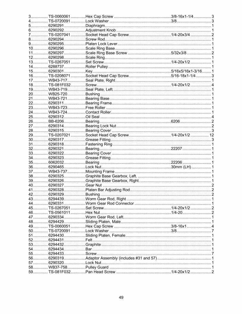
49
3 ............... TS-0060061 .............Hex Cap Screw ..................................................3/8-16x1-1/4 ............... 3 4 ............... TS-0720091 .............Lock Washer ......................................................3/8 .............................. 3 5 ............... 6290291...................Diaphragm............................................................................................. 1 6 ............... 6290292...................Adjustment Knob ................................................................................... 1 7 ............... TS-0207041 .............Socket Head Cap Screw .....................................1/4-20x3/4 .................. 2 8 ............... 6290294...................Screw Rod............................................................................................. 1 9 ............... 6290295...................Platen Lock Lever .................................................................................. 1 10 ............. 6290296...................Scale Ring Base .................................................................................... 1 11 ............. 6290297...................Scale Ring Base Screw ......................................5/32x3/8 ..................... 2 12 ............. 6290298...................Scale Ring ............................................................................................. 1 13 ............. TS-0267051 .............Set Screw ...........................................................1/4-20x1/2 .................. 1 14 ............. 6288737...................Roller Pulley .......................................................................................... 1 15 ............. 6290301...................Key.....................................................................5/16x5/16x1-3/16 ........ 1 16 ............. TS-0208071 .............Socket Head Cap Screw .....................................5/16-18x1-1/4 ............. 3 17 ............. WB43-717 ................Seal Plate, Right .................................................................................... 1 18 ............. TS-081F032 .............Screw .................................................................1/4-20x1/2 .................. 4 19 ............. WB43-719 ................Seal Plate, Left. ..................................................................................... 1 20 ............. WB25-720 ................Bushing ................................................................................................. 1 21 ............. WB43-721 ................Bearing Base ......................................................................................... 1 22 ............. 6290311...................Bearing Frame....................................................................................... 1 23 ............. WB43-723 ................Free Roller ............................................................................................ 1 24 ............. WB43-724 ................Contact Roller........................................................................................ 1 25 ............. 6290312...................Oil Seal ................................................................................................. 4 26 ............. BB-6206...................Bearing...............................................................6206 ........................... 2 27 ............. 6290314...................Bearing Lock Nut ................................................................................... 2 28 ............. 6290315...................Bearing Cover ....................................................................................... 3 29 ............. TS-0207021 .............Socket Head Cap Screw .....................................1/4-20x1/2 ................ 12 30 ............. 6290317...................Grease Fitting ........................................................................................ 3 31 ............. 6290318...................Fastening Ring ...................................................................................... 1 32 ............. 6290321...................Bearing...............................................................22207 ......................... 1 33 ............. 6290322...................Bearing Cover ....................................................................................... 1 34 ............. 6290323...................Grease Fitting ........................................................................................ 1 35 ............. 6062032...................Bearing ..............................................................22206 ......................... 1 36 ............. 6290465...................Lock Nut .............................................................30mm (LH) ................. 1 37 ............. WB43-737 ................Mounting Frame .................................................................................... 1 38 ............. 6290325...................Graphite Base Gearbox, Left. ................................................................ 1 39 ............. 6290326...................Graphite Base Gearbox, Right. .............................................................. 1 40 ............. 6290327...................Gear Nut ............................................................................................... 2 41 ............. 6290328...................Platen Bar Adjusting Rod ....................................................................... 2 42 ............. 6290329...................Bushing ................................................................................................. 2 43 ............. 6294439...................Worm Gear Rod, Right .......................................................................... 1 44 ............. 6290331...................Worm Gear Rod Connector ................................................................... 1 45 ............. TS-0267051 .............Set Screw ...........................................................1/4-20x1/2 .................. 2 46 ............. TS-0561011 .............Hex Nut ..............................................................1/4-20 ......................... 2 47 ............. 6290334...................Worm Gear Rod, Left. ............................................................................ 1 48 ............. 6294429...................Sliding Platen, Male ............................................................................... 1 49 ............. TS-0060051 .............Hex Cap Screw ..................................................3/8-16x1 ..................... 4 50 ............. TS-0720091 .............Lock Washer ......................................................3/8 .............................. 7 51 ............. 6294430...................Sliding Platen, Female ........................................................................... 1 52 ............. 6294431...................Felt ........................................................................................................ 1 53 ............. 6294432...................Graphite ................................................................................................ 1 54 ............. 6294434...................Bar ........................................................................................................ 1 55 ............. 6294433...................Screw .................................................................................................... 7 56 ............. 6290319...................Adaptor Assembly (includes #31 and 57) ............................................... 1 57 ............. 6290320...................Lock Nut ................................................................................................ 1 58 ............. WB37-758 ................Pulley Guard ......................................................................................... 1 59 ............. TS-081F032 .............Pan Head Screw ................................................1/4-20x1/2 .................. 2

50
16.11.1 Air Regulator Assembly – Models WB-25, WB-37, WB-43 Parts list on page 50 (WB-25), page 51 (WB-37) and page 52 (WB-43).
16.11.2 Parts List: Air Regulator Assembly – Model WB-25
Index No. Part No. Description Size Qty ................. WB25-FCA ..............Filter Cup Assembly (index # 1,2,3,5,6,7) ............................................... 1 1 ............... 6294544...................Filter Cup .............................................................................................. 1 2 ............... 6294545...................Pressure Regulator ................................................................................ 1 3 ............... 6294546...................Bronze Connector.................................................................................. 2 4 ............... 6294547...................Flexible Hose......................................................................................... 1 5 ............... 6294548...................Air Switch .............................................................................................. 1 6 ............... 6294549...................Elbow .................................................................................................... 1 7 ............... TS-081C042 ............Screw .................................................................10-24x5/8 ................... 2 8 ............... 6294551...................Elbow .................................................................................................... 2 9 ............... 6294552...................Solenoid Valve ...................................................................................... 1 10 ............. 6294553...................T-Joint ................................................................................................... 1 11 ............. 6294554...................Bronze Connector.................................................................................. 6 12 ............. 6294555...................Multiple Hole Connector ........................................................................ 1 14 ............. 6294557...................Bronze Elbow ........................................................................................ 1 17 ............. 6294560...................Throttle Valve ........................................................................................ 2 18 ............. 6294561...................Bronze Connector.................................................................................. 2 19 ............. 6294562...................Bronze Connector.................................................................................. 1 20 ............. 6294563...................Bronze Connector.................................................................................. 1 21 ............. WB25-921 ................Bronze Connector.................................................................................. 1 22 ............. 6294565...................Air Switch .............................................................................................. 1 25 ............. 6294568...................Buffer .................................................................................................... 2 26 ............. WB25-926 ................Buffer .................................................................................................... 1 28 ............. WB25-928 ................Flexible Hose......................................................ψ8×700mm................. 1

51
Index No. Part No. Description Size Qty 29 ............. 6294571...................Flexible Hose......................................................ψ8×1400mm ............... 1 30 ............. WB25-930 ................Flexible Hose......................................................ψ6×1100mm ............... 1 31 ............. WB25-931 ................Flexible Hose......................................................ψ6×500mm................. 1 32 ............. WB25-932 ................Flexible Hose......................................................ψ6×560mm................. 1 33 ............. 6294664...................Flexible Hose......................................................ψ6×250mm................. 1 34 ............. 6294665...................Flexible Hose......................................................ψ6×650mm................. 1 35 ............. 6294666...................Flexible Hose......................................................ψ6×300mm................. 1 36 ............. 6294667...................Flexible Hose......................................................ψ6×650mm................. 1 37 ............. WB25-937 ................Flexible Hose......................................................ψ6×860mm................. 1 16.11.3 Parts List: Air Regulator Assembly – Model WB-37 Exploded view on page 50.
Index No. Part No. Description Size Qty ................. WB25-FCA ..............Filter Cup Assembly (index # 1,2,3,5,6,7) ............................................... 1 1 ............... 6294544...................Filter Cup .............................................................................................. 1 2 ............... 6294545...................Pressure Regulator ................................................................................ 1 3 ............... 6294546...................Bronze Connector.................................................................................. 2 4 ............... 6294547...................Flexible Hose......................................................................................... 1 5 ............... 6294548...................Air Switch .............................................................................................. 1 6 ............... 6294549...................Elbow .................................................................................................... 1 7 ............... TS-081C042 ............Pan Head Screw ................................................10-24x5/8 ................... 2 8 ............... 6294551...................Elbow .................................................................................................... 2 9 ............... 6294552...................Solenoid Valve ...................................................................................... 1 10 ............. 6294553...................T-Joint ................................................................................................... 1 11 ............. 6294554...................Bronze Connector.................................................................................. 6 12 ............. 6294555...................Multiple Hole Connector ........................................................................ 1 14 ............. 6294557...................Bronze Elbow ........................................................................................ 1 17 ............. 6294560...................Throttle Valve ........................................................................................ 2 18 ............. 6294561...................Bronze Connector.................................................................................. 2 19 ............. 6294562...................Bronze Connector.................................................................................. 1 20 ............. 6294563...................Bronze Connector.................................................................................. 1 21 ............. WB25-921 ................Bronze Connector.................................................................................. 1 22 ............. 6294565...................Air Switch .............................................................................................. 1 25 ............. 6294568...................Buffer .................................................................................................... 2 26 ............. WB25-926 ................Buffer .................................................................................................... 1 28 ............. WB25-928 ................Flexible Hose......................................................ψ8×700mm................. 1 29 ............. 6294571...................Flexible Hose......................................................ψ8×1400mm ............... 1 30 ............. WB37-930 ................Flexible Hose......................................................ψ6×1420mm ............... 1 31 ............. WB37-931 ................Flexible Hose......................................................ψ6×620mm................. 1 32 ............. WB25-932 ................Flexible Hose......................................................ψ6×560mm................. 1 33 ............. 6294664...................Flexible Hose......................................................ψ6×250mm................. 1 34 ............. 6294665...................Flexible Hose......................................................ψ6×650mm................. 1 35 ............. 6294666...................Flexible Hose......................................................ψ6×300mm................. 1 36 ............. 6294667...................Flexible Hose......................................................ψ6×650mm................. 1 37 ............. WB37-937 ................Flexible Hose......................................................ψ6×1350mm ............... 1

52
16.11.4 Parts List: Air Regulator Assembly – Model WB-43 Exploded view on page 50.
Index No. Part No. Description Size Qty ................. WB25-FCA ..............Filter Cup Assembly (index # 1,2,3,5,6,7) ............................................... 1 1 ............... 6294544...................Filter Cup .............................................................................................. 1 2 ............... 6294545...................Pressure Regulator ................................................................................ 1 3 ............... 6294546...................Bronze Connector.................................................................................. 2 4 ............... 6294547...................Flexible Hose......................................................................................... 1 5 ............... 6294548...................Air Switch .............................................................................................. 1 6 ............... 6294549...................Elbow .................................................................................................... 1 7 ............... TS-081C042 ............Screw .................................................................10-24x5/8 ................... 2 8 ............... 6294551...................Elbow .................................................................................................... 2 9 ............... 6294552...................Solenoid Valve ...................................................................................... 1 10 ............. 6294553...................T-Joint ................................................................................................... 3 11 ............. 6294554...................Bronze Connector.................................................................................. 6 12 ............. 6294555...................Multiple Hole Connector ........................................................................ 1 14 ............. 6294557...................Bronze Elbow ........................................................................................ 1 17 ............. 6294560...................Throttle Valve ........................................................................................ 2 18 ............. 6294561...................Bronze Connector.................................................................................. 2 19 ............. 6294562...................Bronze Connector.................................................................................. 1 20 ............. 6294563...................Bronze Connector.................................................................................. 1 21 ............. WB43-921 ................Bronze Connector.................................................................................. 1 22 ............. 6294565...................Air Switch .............................................................................................. 1 25 ............. 6294568...................Buffer .................................................................................................... 2 26 ............. WB25-926 ................Buffer .................................................................................................... 1 28 ............. WB25-928 ................Flexible Hose......................................................ψ8×700mm................. 1 29 ............. 6294571...................Flexible Hose......................................................ψ8×1400mm ............... 1 30 ............. 6294657...................Flexible Hose......................................................ψ6×1600mm ............... 1 31 ............. 6294658...................Flexible Hose......................................................ψ6×750mm................. 1 32 ............. 6294663...................Flexible Hose......................................................ψ6×600mm................. 1 33 ............. 6294664...................Flexible Hose......................................................ψ6×250mm................. 1 34 ............. 6294665...................Flexible Hose......................................................ψ6×650mm................. 1 35 ............. 6294666...................Flexible Hose......................................................ψ6×300mm................. 1 36 ............. 6294667...................Flexible Hose......................................................ψ6×650mm................. 1 37 ............. 6294662...................Flexible Hose......................................................ψ6×1500mm ............... 1

53
16.12.1 Sanding Belt and Accessories – Models WB-25, WB-37, WB-43 Parts list on page 54.

54
16.12.2 Parts List: Sanding Belt and Accessories – Model WB-25 Exploded view on page 53.
Index No. Part No. Description Size Qty 1 ............... 6290281...................Platen Pull Hook .................................................................................... 1 2 ............... 6294461...................Limit Switch Tube .................................................................................. 2 3 ............... WB25-1003 ..............Tool Box ................................................................................................ 1 4 ............... 6288602...................Felt ........................................................................................................ 1 5 ............... 6288603...................Graphite ................................................................................................ 2 6 ............... 6294256...................Door Lock Key ....................................................................................... 2 7 ............... ................................Sanding Belt (local purchase) .............................25”x75” (100 Grit) ....... 1 ................. ................................Sanding Belt (local purchase) .............................25”x75” (180 Grit) ....... 1 8 ............... WB25-1008 ..............Cross Point Screwdriver ........................................................................ 1 9 ............... WB25-1009 ..............Flat Blade Screwdriver ........................................................................... 1 10 ............. WB25-1010 ..............Open End Wrench ..............................................8/10 mm ..................... 1 11 ............. WB25-1011 ..............Open End Wrench ..............................................12/14 mm ................... 1 12 ............. WB25-1012 ..............Open End Wrench ..............................................17/19 mm ................... 1 13 ............. WB25-1013 ..............Hex Wrench Set .................................................................................... 1 14 ............. WB25-1014 ..............Adjusting Rod ........................................................................................ 1 16.12.3 Parts List: Sanding Belt and Accessories – Model WB-37
Index No. Part No. Description Size Qty 1 ............... 6290281...................Platen Pull Hook .................................................................................... 1 2 ............... 6294461...................Limit Switch Tube .................................................................................. 2 3 ............... WB25-1003 ..............Tool Box ................................................................................................ 1 4 ............... 6288702...................Felt ........................................................................................................ 1 5 ............... 6288703...................Graphite ................................................................................................ 2 6 ............... 6294256...................Door Lock Key ....................................................................................... 2 7 ............... ................................Sanding Belt (local purchase) .............................37”×75” (100Grit) ........ 1 ................. ................................Sanding Belt (local purchase) .............................37”×75” (180Grit) ........ 1 8 ............... WB25-1008 ..............Cross Point Screwdriver ........................................................................ 1 9 ............... WB25-1009 ..............Flat Blade Screwdriver ........................................................................... 1 10 ............. WB25-1010 ..............Open End Wrench ..............................................8/10 mm ..................... 1 11 ............. WB25-1011 ..............Open End Wrench ..............................................12/14 mm ................... 1 12 ............. WB25-1012 ..............Open End Wrench ..............................................17/19 mm ................... 1 13 ............. WB25-1013 ..............Hex Wrench Set .................................................................................... 1 14 ............. WB25-1014 ..............Adjusting Rod ........................................................................................ 1 16.12.4 Parts List: Sanding Belt and Accessories – Model WB-43
Index No. Part No. Description Size Qty 1 ............... 6290281...................Platen Pull Hook .................................................................................... 1 2 ............... 6294461...................Limit Switch Tube .................................................................................. 2 3 ............... WB25-1003 ..............Tool Box ................................................................................................ 1 4 ............... 6294431...................Felt ........................................................................................................ 1 5 ............... 6294432...................Graphite ................................................................................................ 2 6 ............... 6294256...................Door Lock Key ....................................................................................... 2 7 ............... ................................Sanding Belt (local purchase) .............................43”×75” (100Grit) ........ 1 ................. ................................Sanding Belt (local purchase) .............................43”×75” (180Grit) ........ 1 8 ............... WB25-1008 ..............Cross Point Screwdriver ........................................................................ 1 9 ............... WB25-1009 ..............Flat Blade Screwdriver ........................................................................... 1 10 ............. WB25-1010 ..............Open End Wrench ..............................................8/10 mm ..................... 1 11 ............. WB25-1011 ..............Open End Wrench ..............................................12/14 mm ................... 1 12 ............. WB25-1012 ..............Open End Wrench ..............................................17/19 mm ................... 1 13 ............. WB25-1013 ..............Hex Wrench Set .................................................................................... 1 14 ............. WB25-1014 ..............Adjusting Rod ........................................................................................ 1

55
16.13.1 Tension Roller Assembly – Models WB-25 and WB-37 ONLY Parts list on page 56 (WB-25) and page 57 (WB-37).

56
16.13.2 Parts List: Tension Roller Assembly – Model WB-25 Exploded view on page 55.
Index No. Part No. Description Size Qty 1. .............. TS-0720111 .............Lock Washer ......................................................1/2 .............................. 1 2. .............. TS-0208041 .............Socket Head Cap Screw .....................................5/16-18x3/4 ................ 6 3 ............... TS-1490031 .............Hex Cap Screw ..................................................M8x20 ........................ 4 4 ............... WB25-104 ................Air Cylinder 63-30 .................................................................................. 1 5 ............... 6294459...................Limit Switch Holder (L Type) .................................................................. 1 6 ............... 6294460...................Limit Switch ........................................................................................... 2 7 ............... 6294653...................Limit Switch ........................................................................................... 1 8 ............... 6294461...................Limit Switch Tube .................................................................................. 2 9 ............... 6294462...................Limit Switch Holder ................................................................................ 2 10 ............. 6294463...................Air Sensor Nozzle (Female) ................................................................... 1 11 ............. 6294464...................Air Cylinder Bracket ............................................................................... 1 12 ............. 6294465...................Air Sensor Nozzle (Male) ....................................................................... 1 13 ............. 6294466...................Throttle Valve ........................................................................................ 1 14 ............. 6294467...................Throttle Valve Base ............................................................................... 1 15 ............. 6294468...................Plate ...................................................................................................... 1 16 ............. 6294469...................Aluminum Disc ...................................................................................... 1 17 ............. 6294470...................Oil Cup .................................................................................................. 1 18 ............. 6294471...................Aluminum Plate ..................................................................................... 1 19 ............. TS-2284202 .............Pan Head Screw ................................................M4x20 ........................ 2 20 ............. WB25-120 ................Sanding Belt Power Off Plate................................................................. 1 21 ............. TS-0561032 .............Hex Nut ..............................................................3/8-24 ......................... 2 22 ............. TS-0680031 .............Flat Washer ........................................................5/16 ............................ 5 23 ............. TS-0720081 .............Lock Washer ......................................................5/16 .......................... 14 24 ............. TS-0081031 .............Hex Cap Screw ..................................................5/16-18x3/4 ................ 5 25 ............. TS-0206041 .............Socket Head Cap Screw .....................................10-24x3/4 ................... 6 26 ............. TS-0560071 .............Hex Nut ..............................................................10-24 .......................... 6 27 ............. 6294478...................Connector, Oil Cap ................................................................................ 1 28 ............. 6294479...................Shaft, Oil Cup ........................................................................................ 1 29 ............. TS-0208111 .............Socket Head Cap Screw .....................................5/16-18x2-1/4 ............. 1 30 ............. TS-1532032 .............Pan Head Screw ................................................M4x10 ........................ 2 31 ............. WB25-131 ................Flat Head Screw .................................................M5x8 .......................... 4 32 ............. WB25-132 ................Upper Roller Frame ............................................................................... 1 33 ............. WB25-133 ................Upper Roller .......................................................................................... 1 34 ............. WB25-134 ................Bearing Housing .................................................................................... 2 35 ............. WB25-135 ................Bearing...............................................................C205 .......................... 2 36 ............. TS-1523011 .............Set Screw ...........................................................M6x6 .......................... 4 37 ............. TS-0209031 .............Socket Head Cap Screw .....................................3/8-16x3/4 .................. 4 38 ............. TS-0720091 .............Lock Washer ......................................................3/8 .............................. 2 39 ............. WB25-139 ................Grease Fitting with Cover ...................................................................... 2 40 ............. 6294490...................Trimming Screw .................................................................................... 1 41 ............. 6294491...................Eccentric Rod ........................................................................................ 1 42 ............. WB25-142 ................Socket Head Cap Screw .....................................1/2-12x3-1/2 ............... 1 43 ............. 6294265...................Copper Plate ......................................................................................... 2 44 ............. 6294493...................Eccentric Piece ...................................................................................... 1 45 ............. 6294494...................Universal Joint Fork ............................................................................... 1 46 ............. JWP15H-224 ...........Retaining Ring ....................................................STW-15 ...................... 1 47 ............. TS-1540071 .............Hex Nut .............................................................M10 ............................ 1 48 ............. 6294496...................Shaft, Air Cylinder.................................................................................. 1 49 ............. WB25-149 ................Hex Nut ..............................................................1/2-12 ......................... 1 56 ............. TS-0720051 .............Lock Washer ......................................................#10 ............................. 6 57 ............. TS-0051011 .............Hex Cap Screw ..................................................5/16-18x1/2 ................ 3 59 ............. WB25-159 ................Eccentric Shaft Housing ........................................................................ 1 60 ............. TS-0561021 .............Hex Nut ..............................................................5/16-18 ....................... 1

57
Index No. Part No. Description Size Qty 61 ............. TS-1533032 .............Pan Head Screw ................................................M5x10 ........................ 6 62 ............. WB25-162 ................Seal ....................................................................................................... 1 63 ............. WB25-ACA ..............Air Cylinder Assembly ............................................................................ 1 16.13.3 Parts List: Tension Roller Assembly – Model WB-37 Exploded view on page 55.
Index No. Part No. Description Size Qty 1 ............... TS-0720111 .............Lock Washer ......................................................1/2 .............................. 1 2. .............. TS-0208041 .............Socket Head Cap Screw .....................................5/16-18x3/4 ................ 6 3 ............... TS-1490031 .............Hex Cap Screw ..................................................M8x20 ........................ 4 4 ............... WB25-104 ................Air Cylinder 63-30 .................................................................................. 1 5 ............... 6294459...................Limit Switch Holder (L Type) .................................................................. 1 6 ............... 6294460...................Limit Switch ........................................................................................... 2 7 ............... 6294653...................Limit Switch ........................................................................................... 1 8 ............... 6294461...................Limit Switch Tube .................................................................................. 2 9 ............... 6294462...................Limit Switch Holder ................................................................................ 2 10 ............. 6294463...................Air Sensor Nozzle (Female) ................................................................... 1 11 ............. 6294464...................Air Cylinder Bracket ............................................................................... 1 12 ............. 6294465...................Air Sensor Nozzle (Male) ....................................................................... 1 13 ............. 6294466...................Throttle Valve ........................................................................................ 1 14 ............. 6294467...................Throttle Valve Base ............................................................................... 1 15 ............. 6294468...................Plate ...................................................................................................... 1 16 ............. 6294469...................Aluminum Disc ...................................................................................... 1 17 ............. 6294470...................Oil Cup .................................................................................................. 1 18 ............. 6294471...................Aluminum Plate ..................................................................................... 1 19 ............. TS-2284202 .............Pan Head Screw ................................................M4x20 ........................ 2 20 ............. WB25-120 ................Sanding Belt Power Off Plate................................................................. 1 21 ............. TS-0561032 .............Hex Nut ..............................................................3/8-24 ......................... 2 22 ............. TS-0680031 .............Flat Washer ........................................................5/16 ............................ 5 23 ............. TS-0720081 .............Lock Washer ......................................................5/16 .......................... 14 24 ............. TS-0081031 .............Hex Cap Screw ..................................................5/16-18x3/4 ................ 5 25 ............. TS-0206041 .............Socket Head Cap Screw .....................................10-24x3/4 ................... 6 26 ............. TS-0560071 .............Hex Nut ..............................................................10-24 .......................... 6 27 ............. 6294478...................Connector, Oil Cap ................................................................................ 1 28 ............. 6294479...................Shaft, Oil Cup ........................................................................................ 1 29 ............. TS-0208111 .............Socket Head Cap Screw .....................................5/16-18x2-1/4 ............. 1 30 ............. TS-1532032 .............Pan Head Screw ................................................M4x10 ........................ 2 31 ............. WB25-131 ................Flat Head Screw .................................................M5x8 .......................... 4 32 ............. WB37-132 ................Upper Roller Frame ............................................................................... 1 33 ............. WB37-133 ................Upper Roller .......................................................................................... 1 34 ............. WB25-134 ................Bearing Housing .................................................................................... 2 35 ............. WB25-135 ................Bearing...............................................................C205 .......................... 2 36 ............. TS-1523011 .............Set Screw ...........................................................M6x6 .......................... 4 37 ............. TS-0209031 .............Socket Head Cap Screw .....................................3/8-16x3/4 .................. 4 38 ............. TS-0720091 .............Lock Washer ......................................................3/8 .............................. 2 39 ............. WB25-139 ................Grease Fitting with Cover ...................................................................... 2 40 ............. 6294490...................Trimming Screw .................................................................................... 1 41 ............. 6294491...................Eccentric Rod ........................................................................................ 1 42 ............. WB25-142 ................Socket Head Cap Screw .....................................1/2-12x3-1/2 ............... 1 43 ............. 6294265...................Copper Plate ......................................................................................... 2 44 ............. 6294493...................Eccentric Piece ...................................................................................... 1 45 ............. 6294494...................Universal Joint Fork ............................................................................... 1 46 ............. JWP15H-224 ...........Retaining Ring ....................................................STW-15 ...................... 1 47 ............. TS-1540071 .............Hex Nut .............................................................M10 ............................ 1 48 ............. 6294496...................Shaft, Air Cylinder.................................................................................. 1
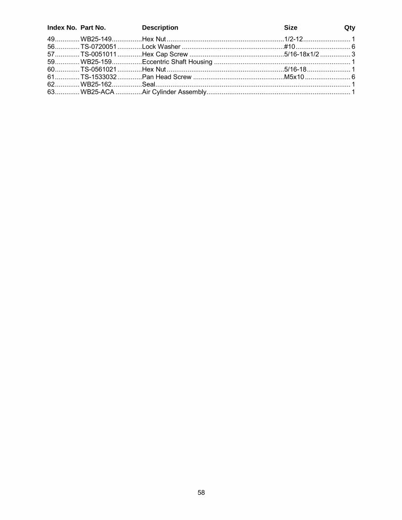
58
Index No. Part No. Description Size Qty 49 ............. WB25-149 ................Hex Nut ..............................................................1/2-12 ......................... 1 56 ............. TS-0720051 .............Lock Washer ......................................................#10 ............................. 6 57 ............. TS-0051011 .............Hex Cap Screw ..................................................5/16-18x1/2 ................ 3 59 ............. WB25-159 ................Eccentric Shaft Housing ........................................................................ 1 60 ............. TS-0561021 .............Hex Nut ..............................................................5/16-18 ....................... 1 61 ............. TS-1533032 .............Pan Head Screw ................................................M5x10 ........................ 6 62 ............. WB25-162 ................Seal ....................................................................................................... 1 63 ............. WB25-ACA ..............Air Cylinder Assembly ............................................................................ 1

59
16.14.1 Tension Roller Assembly – Model WB-43 ONLY Parts list on page 60.

60
16.14.2 Parts List: Tension Roller Assembly – Model WB-43 Exploded view on page 59.
Index No. Part No. Description Size Qty 1 ............... WB25-162 ................Seal ....................................................................................................... 1 2. .............. TS-0720111 .............Lock Washer ......................................................1/2 .............................. 7 3 ............... TS-0208041 .............Socket Head Cap Screw .....................................5/16-18x3/4 ................ 6 4 ............... TS-0208041 .............Socket Head Cap Screw .....................................5/16-18x3/4 ................ 4 5 ............... 6294458...................Air Cylinder ............................................................................................ 1 6 ............... 6294459...................Limit Switch Holder (L Type) .................................................................. 1 7 ............... 6294460...................Limit Switch .......................................................................................... 2 8 ............... 6294653...................Limit Switch ........................................................................................... 1 9 ............... 6294461...................Limit Switch Tube .................................................................................. 2 10 ............. 6294462...................Limit Switch Holder ................................................................................ 2 11 ............. 6294463...................Air Sensor Nozzle (Female) ................................................................... 1 12 ............. 6294464...................Air Cylinder Bracket ............................................................................... 1 13 ............. 6294465...................Air Sensor Nozzle (Male) ....................................................................... 1 14 ............. 6294466...................Throttle Valve ........................................................................................ 1 15 ............. 6294467...................Throttle Valve Base ............................................................................... 1 16 ............. 6294468...................Plate ...................................................................................................... 1 17 ............. 6294469...................Aluminum Disc ...................................................................................... 1 18 ............. 6294470...................Oil Cup .................................................................................................. 1 19 ............. 6294471...................Aluminum Plate ..................................................................................... 1 20 ............. TS-2284202 .............Pan Head Screw ................................................M4x20 ........................ 2 21 ............. 6294473...................Sanding Belt Power Off Plate................................................................. 1 22 ............. TS-0561032 .............Hex Nut ..............................................................3/8-24 ......................... 2 23 ............. TS-0680031 .............Flat Washer ........................................................5/16 ............................ 5 24 ............. TS-0720081 .............Lock Washer ......................................................5/16 .......................... 14 25 ............. TS-0206041 .............Socket Head Cap Screw .....................................10-24x3/4 ................... 6 26 ............. TS-0560071 .............Hex Nut ..............................................................10-24 .......................... 6 27 ............. TS-0081031 .............Hex Cap Screw ..................................................5/16-18x3/4 ................ 5 28 ............. 6294478...................Connector, Oil Cap ................................................................................ 1 29 ............. 6294479...................Shaft, Oil Cup ........................................................................................ 1 30 ............. WB43-130 ................Hex Cap Screw ..................................................1/2-12x1 ..................... 4 31 ............. WB43-131 ................Socket Head Cap Screw .....................................1/2-12x1-3/4 ............... 2 32 ............. TS-0208081 .............Socket Head Cap Screw .....................................5/16-18x1-1/2 ............. 1 33 ............. TS-1532032 .............Pan Head Screw ................................................M4x10 ........................ 2 34 ............. WB25-131 ................Flat Head Screw .................................................M5x8 .......................... 4 35 ............. WB43-135 ................Upper Roller Frame ............................................................................... 2 36 ............. WB43-136 ................Upper Roller .......................................................................................... 1 37 ............. WB25-134 ................Bearing Housing .................................................................................... 2 38 ............. WB25-135 ................Bearing...............................................................C205 .......................... 2 39 ............. TS-1523011 .............Set Screw ...........................................................M6x6 .......................... 4 40 ............. TS-0209031 .............Socket Head Cap Screw .....................................3/8-16x3/4 .................. 4 41 ............. TS-0720091 .............Lock Washer ......................................................3/8 .............................. 2 42 ............. WB25-139 ................Grease Fitting with Cover ...................................................................... 2 43 ............. 6294490...................Trimming Screw .................................................................................... 1 44 ............. 6294491...................Eccentric Rod ........................................................................................ 1 45 ............. WB25-142 ................Socket Head Cap Screw .....................................1/2-12x3-1/2 ............... 1 46 ............. JWP15H-224 ...........Retaining Ring ....................................................STW-15 ...................... 1 47 ............. 6294493...................Eccentric Piece ...................................................................................... 1 48 ............. 6294496...................Shaft, Air Cylinder.................................................................................. 1 49 ............. 6294265...................Copper Plate ......................................................................................... 2 56 ............. TS-0720051 .............Lock Washer ......................................................#10 ............................. 6 57 ............. TS-1540071 .............Hex Nut .............................................................M10 ............................ 1 58 ............. 6294494...................Universal Joint Fork ............................................................................... 1 59 ............. WB25-149 ................Hex Nut ..............................................................1/2-12 ......................... 1 60 ............. TS-0561021 .............Hex Nut ..............................................................5/16-18 ....................... 1 62 ............. WB25-159 ................Eccentric Shaft Housing ........................................................................ 1

61
Index No. Part No. Description Size Qty 63 ............. WB43-163 ................Frame Support ...................................................................................... 1 64 ............. TS-1533032 .............Pan Head Screw ................................................M5x10 ........................ 6 65 ............. TS-0051011 .............Hex Cap Screw ..................................................5/16-18x1/2 ................ 4 66 ............. WB43-ACA ..............Air Cylinder Assembly ............................................................................ 1

62
16.15.1 Electrical Box Assembly – Models WB-25 and WB-37 Parts list on page 63 (WB-25) and 64 (WB-37).

63
16.15.2 Parts List: Electrical Box Assembly – Model WB-25 Exploded view on page 62.
Index No. Part No. Description Size Qty 1 ............... WB25-801 ................Electrical Control Box ........................................................................... 1 2 ............... 6294516...................Hinge Pin .............................................................................................. 2 3 ............... WB25-803 ................Electrical Control Box Door .................................................................... 1 4 ............... WB25-804 ................Base Plate ............................................................................................. 1 5 ............... TS-0561011 .............Hex Nut ..............................................................1/4-20 ......................... 4 6 ............... TS-0720071 .............Lock Washer ......................................................1/4 .............................. 4 7 ............... WB25-807 ................Control Panel......................................................................................... 1 8 ............... WB25-808 ................Button Head Socket Screw .................................M4x8 .......................... 4 9 ............... WB25-809 ................Proportional Current Device ................................................................... 1 10 ............. WB25-810 ................Transformer ........................................................................................... 1 11 ............. WB25-811 ................Contactor .............................................................................................. 1 12 ............. WB25-812 ................Overload Relay (for 230V) ..................................................................... 1 ................. WB25-812A .............Overload Relay (for 460V) ..................................................................... 1 13 ............. WB25-813 ................Fuse ..................................................................4A .............................. 2 14 ............. WB25-814 ................Overload Relay (for 230V) ..................................................................... 1 ................. WB25-814A .............Overload Relay (for 460V) ..................................................................... 1 15 ............. 6294647...................Contactor ...........................................................CN-11......................... 3 16 ............. WB25-816 ................Wire Column ......................................................................................... 1 17 ............. WB25-817 ................Controller .............................................................................................. 1 18 ............. WB25-818 ................Power Wire Terminal ............................................................................. 1 19 ............. WB25-819 ................Tap Screw ..........................................................M4x10 ........................ 2 20 ............. WB25-820 ................Terminal Board ...................................................................................... 8 21 ............. TS-0680021 .............Flat Washer ........................................................1/4 .............................. 4 22 ............. TS-0720071 .............Lock Washer ......................................................1/4 .............................. 4 23 ............. TS-081F032 .............Pan Head Screw ................................................1/4-20x1/2 .................. 4 24 ............. 6294532...................PU Connector 1/2” ................................................................................. 4 25 ............. 6294533...................PU Connector 3/4” ................................................................................. 3 26 ............. 6294534...................Cable Connector 1” ............................................................................... 1 27 ............. WB25-827 ................Amp Meter............................................................................................. 1 28 ............. 6294537...................Start Switch ........................................................................................... 2 29 ............. 6294538...................Stop Switch ........................................................................................... 2 30 ............. 6294539...................Power Indication Light ........................................................................... 1 31 ............. 6294540...................Emergency Stop Switch ......................................................................... 1 32 ............. WB25-832 ................Fuse Support Base ................................................................................ 2 33 ............. WB25-833 ................Contactor (Feed Motor only) .................................................................. 1 34 ............. WB25-834 ................Plate ...................................................................................................... 1
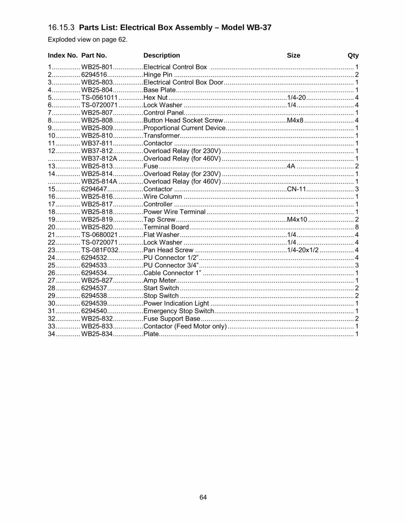
64
16.15.3 Parts List: Electrical Box Assembly – Model WB-37 Exploded view on page 62.
Index No. Part No. Description Size Qty 1 ............... WB25-801 ................Electrical Control Box ........................................................................... 1 2 ............... 6294516...................Hinge Pin .............................................................................................. 2 3 ............... WB25-803 ................Electrical Control Box Door .................................................................... 1 4 ............... WB25-804 ................Base Plate ............................................................................................. 1 5 ............... TS-0561011 .............Hex Nut ..............................................................1/4-20 ......................... 4 6 ............... TS-0720071 .............Lock Washer ......................................................1/4 .............................. 4 7 ............... WB25-807 ................Control Panel......................................................................................... 1 8 ............... WB25-808 ................Button Head Socket Screw .................................M4x8 .......................... 4 9 ............... WB25-809 ................Proportional Current Device ................................................................... 1 10 ............. WB25-810 ................Transformer ........................................................................................... 1 11 ............. WB37-811 ................Contactor .............................................................................................. 1 12 ............. WB37-812 ................Overload Relay (for 230V) ..................................................................... 1 ................. WB37-812A .............Overload Relay (for 460V) ..................................................................... 1 13 ............. WB25-813 ................Fuse ...................................................................4A .............................. 2 14 ............. WB25-814 ................Overload Relay (for 230V) ..................................................................... 1 ................. WB25-814A .............Overload Relay (for 460V) ..................................................................... 1 15 ............. 6294647...................Contactor ...........................................................CN-11......................... 3 16 ............. WB25-816 ................Wire Column ......................................................................................... 1 17 ............. WB25-817 ................Controller .............................................................................................. 1 18 ............. WB25-818 ................Power Wire Terminal ............................................................................. 1 19 ............. WB25-819 ................Tap Screw ..........................................................M4x10 ........................ 2 20 ............. WB25-820 ................Terminal Board ...................................................................................... 8 21 ............. TS-0680021 .............Flat Washer ........................................................1/4 .............................. 4 22 ............. TS-0720071 .............Lock Washer ......................................................1/4 .............................. 4 23 ............. TS-081F032 .............Pan Head Screw ................................................1/4-20x1/2 .................. 4 24 ............. 6294532...................PU Connector 1/2” ................................................................................. 4 25 ............. 6294533...................PU Connector 3/4” ................................................................................. 3 26 ............. 6294534...................Cable Connector 1” ............................................................................... 1 27 ............. WB25-827 ................Amp Meter............................................................................................. 1 28 ............. 6294537...................Start Switch ........................................................................................... 2 29 ............. 6294538...................Stop Switch ........................................................................................... 2 30 ............. 6294539...................Power Indication Light ........................................................................... 1 31 ............. 6294540...................Emergency Stop Switch ......................................................................... 1 32 ............. WB25-832 ................Fuse Support Base ................................................................................ 2 33 ............. WB25-833 ................Contactor (Feed Motor only) .................................................................. 1 34 ............. WB25-834 ................Plate ...................................................................................................... 1

65
16.16.1 Electrical Box Assembly – Model WB-43 ONLY Parts list on page 66.

66
16.16.2 Parts List: Electrical Box Assembly – Model WB-43 Exploded view on page 65.
Index No. Part No. Description Size Qty 1 ............... WB43-801 ................Electrical Control Box ........................................................................... 1 2 ............... 6294516...................Hinge Pin .............................................................................................. 2 3 ............... WB43-803 ................Electrical Control Box Door .................................................................... 1 4 ............... 6294518...................Base Plate ............................................................................................. 1 5 ............... TS-0561011 .............Hex Nut ..............................................................1/4-20 ......................... 4 6 ............... TS-0720071 .............Lock Washer ......................................................1/4 .............................. 4 7 ............... WB25-807 ................Control Panel......................................................................................... 1 8 ............... WB25-808 ................Button Head Socket Screw .................................M4x8 .......................... 4 9 ............... WB25-809 ................Proportional Current Device ................................................................... 1 10 ............. WB43-810 ................Transformer ........................................................................................... 1 11 ............. 6294523...................Contactor ...........................................................CN-35......................... 2 12 ............. 6294540...................Emergency Stop Switch ......................................................................... 1 13 ............. WB25-832 ................Fuse Support Base ................................................................................ 2 14 ............. WB43-814 ................Overload Relay (for 230V) ..................................................................... 1 ................. WB43-814A .............Overload Relay (for 460V) ..................................................................... 1 15 ............. WB25-813 ................Fuse ...................................................................4A .............................. 2 16 ............. WB43-816 ................Overload Relay (for 230V) ..................................................................... 1 ................. WB43-816A .............Overload Relay (for 460V) ..................................................................... 1 17 ............. 6294647...................Contactor ...........................................................CN-11......................... 3 18 ............. WB43-818 ................Wire Column ......................................................................................... 1 19 ............. WB43-819 ................Wire Column ......................................................................................... 1 20 ............. WB25-817 ................Controller .............................................................................................. 1 21 ............. WB43-821 ................Power Wire Terminal ............................................................................. 1 22 ............. WB25-819 ................Tap Screw ..........................................................M4x10 ........................ 2 23 ............. WB43-823 ................Terminal Board ...................................................................................... 8 24 ............. TS-0680021 .............Flat Washer ........................................................1/4 .............................. 4 25 ............. TS-0720071 .............Lock Washer ......................................................1/4 .............................. 4 26 ............. TS-081F032 .............Pan Head Screw ................................................1/4-20x1/2 .................. 4 27 ............. 6294532...................PU Connector 1/2” ................................................................................. 4 28 ............. 6294533...................PU Connector 3/4” ................................................................................. 3 29 ............. 6294534...................Cable Connector 1” ............................................................................... 1 30 ............. WB25-827 ................Amp Meter............................................................................................. 1 31 ............. WB43-831 ................Timer ..................................................................................................... 1 32 ............. 6294537...................Start Switch ........................................................................................... 2 33 ............. 6294538...................Stop Switch ........................................................................................... 2 34 ............. 6294539...................Power Indication Light ........................................................................... 1 35 ............. 6294645...................Contactor ...........................................................CN-25......................... 1 36 ............. WB25-833 ................Contactor (Feed Motor only) .................................................................. 1 37 ............. WB25-834 ................Plate ...................................................................................................... 1

67
17.0 Electrical Connections 17.1 Models WB-25 and WB-37 ONLY

68
17.2 Model WB-43 ONLY