
Operating Instructions and Parts Manual Geared Head Drilling/Tapping...
40
Operating Instructions and Parts Manual Geared Head Drilling/Tapping Presses Models GHD-20/20T/20PF/20PFT Model GHD-20PFT shown JET 427 New Sanford Road LaVergne, Tennessee 37086 Part No. M-354026 Ph.: 800-274-6848 Revision J2 12/2017 www.jettools.com Copyright © 2017 JET
-
Upload
trinhquynh -
Category
Documents
-
view
217 -
download
1
Transcript of Operating Instructions and Parts Manual Geared Head Drilling/Tapping...

Operating Instructions and Parts Manual Geared Head Drilling/Tapping Presses Models GHD-20/20T/20PF/20PFT
Model GHD-20PFT shown
JET 427 New Sanford Road LaVergne, Tennessee 37086 Part No. M-354026 Ph.: 800-274-6848 Revision J2 12/2017 www.jettools.com Copyright © 2017 JET
Tom Gauger
This .pdf document is bookmarked
2
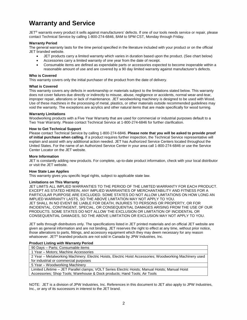
Warranty and Service JET® warrants every product it sells against manufacturers’ defects. If one of our tools needs service or repair, please contact Technical Service by calling 1-800-274-6846, 8AM to 5PM CST, Monday through Friday.
Warranty Period The general warranty lasts for the time period specified in the literature included with your product or on the official JET branded website.
• JET products carry a limited warranty which varies in duration based upon the product. (See chart below) • Accessories carry a limited warranty of one year from the date of receipt. • Consumable items are defined as expendable parts or accessories expected to become inoperable within a
reasonable amount of use and are covered by a 90 day limited warranty against manufacturer’s defects.
Who is Covered This warranty covers only the initial purchaser of the product from the date of delivery.
What is Covered This warranty covers any defects in workmanship or materials subject to the limitations stated below. This warranty does not cover failures due directly or indirectly to misuse, abuse, negligence or accidents, normal wear-and-tear, improper repair, alterations or lack of maintenance. JET woodworking machinery is designed to be used with Wood. Use of these machines in the processing of metal, plastics, or other materials outside recommended guidelines may void the warranty. The exceptions are acrylics and other natural items that are made specifically for wood turning.
Warranty Limitations Woodworking products with a Five Year Warranty that are used for commercial or industrial purposes default to a Two Year Warranty. Please contact Technical Service at 1-800-274-6846 for further clarification.
How to Get Technical Support Please contact Technical Service by calling 1-800-274-6846. Please note that you will be asked to provide proof of initial purchase when calling. If a product requires further inspection, the Technical Service representative will explain and assist with any additional action needed. JET has Authorized Service Centers located throughout the United States. For the name of an Authorized Service Center in your area call 1-800-274-6846 or use the Service Center Locator on the JET website.
More Information JET is constantly adding new products. For complete, up-to-date product information, check with your local distributor or visit the JET website.
How State Law Applies This warranty gives you specific legal rights, subject to applicable state law.
Limitations on This Warranty JET LIMITS ALL IMPLIED WARRANTIES TO THE PERIOD OF THE LIMITED WARRANTY FOR EACH PRODUCT. EXCEPT AS STATED HEREIN, ANY IMPLIED WARRANTIES OF MERCHANTABILITY AND FITNESS FOR A PARTICULAR PURPOSE ARE EXCLUDED. SOME STATES DO NOT ALLOW LIMITATIONS ON HOW LONG AN IMPLIED WARRANTY LASTS, SO THE ABOVE LIMITATION MAY NOT APPLY TO YOU. JET SHALL IN NO EVENT BE LIABLE FOR DEATH, INJURIES TO PERSONS OR PROPERTY, OR FOR INCIDENTAL, CONTINGENT, SPECIAL, OR CONSEQUENTIAL DAMAGES ARISING FROM THE USE OF OUR PRODUCTS. SOME STATES DO NOT ALLOW THE EXCLUSION OR LIMITATION OF INCIDENTAL OR CONSEQUENTIAL DAMAGES, SO THE ABOVE LIMITATION OR EXCLUSION MAY NOT APPLY TO YOU. JET sells through distributors only. The specifications listed in JET printed materials and on official JET website are given as general information and are not binding. JET reserves the right to effect at any time, without prior notice, those alterations to parts, fittings, and accessory equipment which they may deem necessary for any reason whatsoever. JET® branded products are not sold in Canada by JPW Industries, Inc.
Product Listing with Warranty Period 90 Days – Parts; Consumable items 1 Year – Motors; Machine Accessories 2 Year – Metalworking Machinery; Electric Hoists, Electric Hoist Accessories; Woodworking Machinery used for industrial or commercial purposes 5 Year – Woodworking Machinery Limited Lifetime – JET Parallel clamps; VOLT Series Electric Hoists; Manual Hoists; Manual Hoist Accessories; Shop Tools; Warehouse & Dock products; Hand Tools; Air Tools
NOTE: JET is a division of JPW Industries, Inc. References in this document to JET also apply to JPW Industries, Inc., or any of its successors in interest to the JET brand.
3
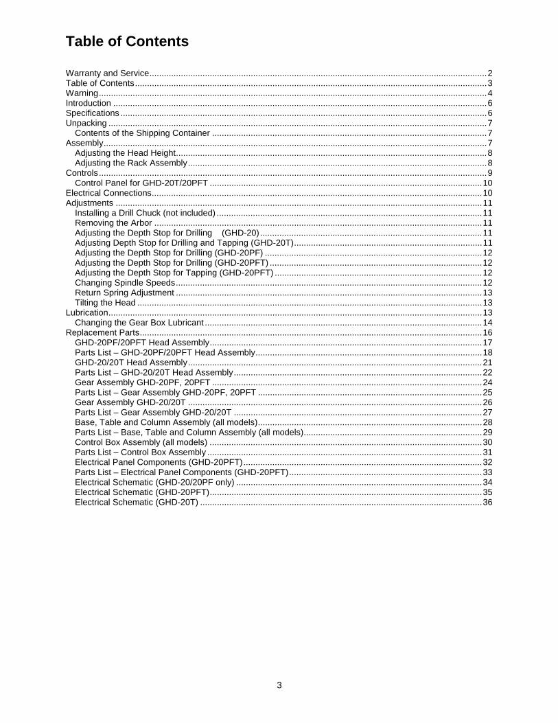
Table of Contents Warranty and Service ............................................................................................................................................ 2 Table of Contents .................................................................................................................................................. 3 Warning ................................................................................................................................................................. 4 Introduction ........................................................................................................................................................... 6 Specifications ........................................................................................................................................................ 6 Unpacking ............................................................................................................................................................. 7
Contents of the Shipping Container .................................................................................................................. 7 Assembly ............................................................................................................................................................... 7
Adjusting the Head Height ................................................................................................................................. 8 Adjusting the Rack Assembly ............................................................................................................................ 8
Controls ................................................................................................................................................................. 9 Control Panel for GHD-20T/20PFT ................................................................................................................. 10
Electrical Connections ......................................................................................................................................... 10 Adjustments ........................................................................................................................................................ 11
Installing a Drill Chuck (not included) .............................................................................................................. 11 Removing the Arbor ........................................................................................................................................ 11 Adjusting the Depth Stop for Drilling (GHD-20) ............................................................................................ 11 Adjusting Depth Stop for Drilling and Tapping (GHD-20T) .............................................................................. 11 Adjusting the Depth Stop for Drilling (GHD-20PF) .......................................................................................... 12 Adjusting the Depth Stop for Drilling (GHD-20PFT) ........................................................................................ 12 Adjusting the Depth Stop for Tapping (GHD-20PFT) ...................................................................................... 12 Changing Spindle Speeds ............................................................................................................................... 12 Return Spring Adjustment ............................................................................................................................... 13 Tilting the Head ............................................................................................................................................... 13
Lubrication ........................................................................................................................................................... 13 Changing the Gear Box Lubricant ................................................................................................................... 14
Replacement Parts .............................................................................................................................................. 16 GHD-20PF/20PFT Head Assembly ................................................................................................................. 17 Parts List – GHD-20PF/20PFT Head Assembly .............................................................................................. 18 GHD-20/20T Head Assembly .......................................................................................................................... 21 Parts List – GHD-20/20T Head Assembly ....................................................................................................... 22 Gear Assembly GHD-20PF, 20PFT ................................................................................................................ 24 Parts List – Gear Assembly GHD-20PF, 20PFT ............................................................................................. 25 Gear Assembly GHD-20/20T .......................................................................................................................... 26 Parts List – Gear Assembly GHD-20/20T ....................................................................................................... 27 Base, Table and Column Assembly (all models) ............................................................................................. 28 Parts List – Base, Table and Column Assembly (all models) .......................................................................... 29 Control Box Assembly (all models) ................................................................................................................. 30 Parts List – Control Box Assembly .................................................................................................................. 31 Electrical Panel Components (GHD-20PFT) ................................................................................................... 32 Parts List – Electrical Panel Components (GHD-20PFT) ................................................................................ 33 Electrical Schematic (GHD-20/20PF only) ...................................................................................................... 34 Electrical Schematic (GHD-20PFT) ................................................................................................................. 35 Electrical Schematic (GHD-20T) ..................................................................................................................... 36
4
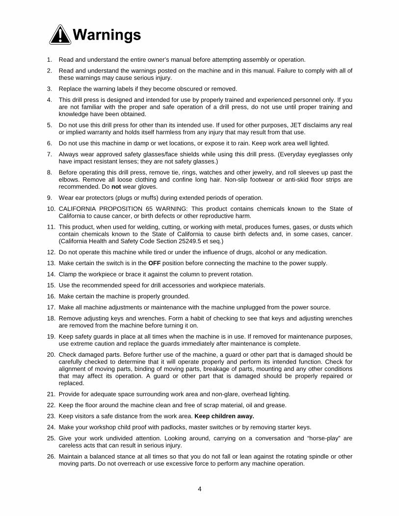
Warning
1. Read and understand the entire owner’s manual before attempting assembly or operation.
2. Read and understand the warnings posted on the machine and in this manual. Failure to comply with all of these warnings may cause serious injury.
3. Replace the warning labels if they become obscured or removed.
4. This drill press is designed and intended for use by properly trained and experienced personnel only. If you are not familiar with the proper and safe operation of a drill press, do not use until proper training and knowledge have been obtained.
5. Do not use this drill press for other than its intended use. If used for other purposes, JET disclaims any real or implied warranty and holds itself harmless from any injury that may result from that use.
6. Do not use this machine in damp or wet locations, or expose it to rain. Keep work area well lighted.
7. Always wear approved safety glasses/face shields while using this drill press. (Everyday eyeglasses only have impact resistant lenses; they are not safety glasses.)
8. Before operating this drill press, remove tie, rings, watches and other jewelry, and roll sleeves up past the elbows. Remove all loose clothing and confine long hair. Non-slip footwear or anti-skid floor strips are recommended. Do not wear gloves.
9. Wear ear protectors (plugs or muffs) during extended periods of operation.
10. CALIFORNIA PROPOSITION 65 WARNING: This product contains chemicals known to the State of California to cause cancer, or birth defects or other reproductive harm.
11. This product, when used for welding, cutting, or working with metal, produces fumes, gases, or dusts which contain chemicals known to the State of California to cause birth defects and, in some cases, cancer. (California Health and Safety Code Section 25249.5 et seq.)
12. Do not operate this machine while tired or under the influence of drugs, alcohol or any medication.
13. Make certain the switch is in the OFF position before connecting the machine to the power supply.
14. Clamp the workpiece or brace it against the column to prevent rotation.
15. Use the recommended speed for drill accessories and workpiece materials.
16. Make certain the machine is properly grounded.
17. Make all machine adjustments or maintenance with the machine unplugged from the power source.
18. Remove adjusting keys and wrenches. Form a habit of checking to see that keys and adjusting wrenches are removed from the machine before turning it on.
19. Keep safety guards in place at all times when the machine is in use. If removed for maintenance purposes, use extreme caution and replace the guards immediately after maintenance is complete.
20. Check damaged parts. Before further use of the machine, a guard or other part that is damaged should be carefully checked to determine that it will operate properly and perform its intended function. Check for alignment of moving parts, binding of moving parts, breakage of parts, mounting and any other conditions that may affect its operation. A guard or other part that is damaged should be properly repaired or replaced.
21. Provide for adequate space surrounding work area and non-glare, overhead lighting.
22. Keep the floor around the machine clean and free of scrap material, oil and grease.
23. Keep visitors a safe distance from the work area. Keep children away.
24. Make your workshop child proof with padlocks, master switches or by removing starter keys.
25. Give your work undivided attention. Looking around, carrying on a conversation and “horse-play” are careless acts that can result in serious injury.
26. Maintain a balanced stance at all times so that you do not fall or lean against the rotating spindle or other moving parts. Do not overreach or use excessive force to perform any machine operation.

5
27. Use the right tool at the correct speed and feed rate. Do not force a tool or attachment to do a job for which
it was not designed. The right tool will do the job better and more safely.
28. Use recommended accessories; improper accessories may be hazardous.
29. Maintain tools with care. Keep cutting tools sharp and clean for the best and safest performance. Follow instructions for lubricating and changing accessories.
30. Make sure the workpiece is securely attached or clamped to the table. Never use your hand to hold the work piece.
31. Turn off the machine and disconnect from power before cleaning. Use a brush or compressed air to remove chips or debris — do not use your hands.
32. Do not stand on the machine. Serious injury could occur if the machine tips over.
33. Never leave the machine running unattended. Turn the power off and do not leave the machine until it comes to a complete stop.
34. Remove loose items and unnecessary work pieces from the area before starting the machine.
Familiarize yourself with the following safety notices used in this manual:
This means that if precautions are not heeded, it may result in minor injury and/or possible machine damage.
This means that if precautions are not heeded, it may result in serious or even fatal injury.
- - SAVE THESE INSTRUCTIONS - -
6
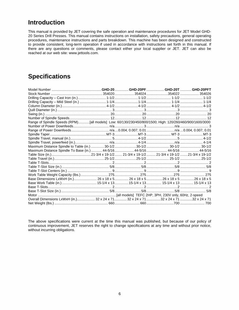
Introduction This manual is provided by JET covering the safe operation and maintenance procedures for JET Model GHD-20 Series Drill Presses. This manual contains instructions on installation, safety precautions, general operating procedures, maintenance instructions and parts breakdown. This machine has been designed and constructed to provide consistent, long-term operation if used in accordance with instructions set forth in this manual. If there are any questions or comments, please contact either your local supplier or JET. JET can also be reached at our web site: www.jettools.com.
Specifications Model Number ..................................................... GHD-20 ............... GHD-20PF ................... GHD-20T ............ GHD-20PFT Stock Number ....................................................... 354020 ..................... 354024 .......................354022 .................... 354026 Drilling Capacity – Cast Iron (in.) .............................. 1-1/2 ......................... 1-1/2 .......................... 1-1/2 ........................ 1-1/2 Drilling Capacity – Mild Steel (in.) ............................ 1-1/4 ......................... 1-1/4 .......................... 1-1/4 ........................ 1-1/4 Column Diameter (in.) ............................................... 4-1/2 ......................... 4-1/2 .......................... 4-1/2 ........................ 4-1/2 Quill Diameter (in.) .......................................................... 3 ............................... 3 ................................. 3 .............................. 3 Swing (in.) ..................................................................... 20 ............................. 20 ............................... 20 ............................ 20 Number of Spindle Speeds ........................................... 12 ............................. 12 ............................... 12 ............................ 12 Range of Spindle Speeds (RPM)............[all models] Low: 60/130/230/450/800/1500; High: 120/260/460/900/1600/3000 Number of Power Downfeeds ...................................... n/a ............................... 3 .............................. n/a .............................. 3 Range of Power Downfeeds ........................................ n/a .... 0.004, 0.007, 0.01 .............................. n/a ... 0.004, 0.007, 0.01 Spindle Taper ............................................................ MT-3 ......................... MT-3 .......................... MT-3 ........................ MT-3 Spindle Travel, manual (in.) ............................................ 5 ......................... 4-1/2 ................................. 5 ........................ 4-1/2 Spindle Travel, powerfeed (in.).................................... n/a ......................... 4-1/4 .............................. n/a ........................ 4-1/4 Maximum Distance Spindle to Table (in.) .............. 30-1/2 ....................... 30-1/2 ........................ 30-1/2 ...................... 30-1/2 Maximum Distance Spindle To Base (in.) ............ 44-5/16 ..................... 44-5/16 ...................... 44-5/16 .................... 44-5/16 Table Size (in.) .......................................... 21-3/4 x 19-1/2 ........ 21-3/4 x 19-1/2 .......... 21-3/4 x 19-1/2 ........ 21-3/4 x 19-1/2 Table Travel (in.) ..................................................... 25-1/2 ....................... 25-1/2 ........................ 25-1/2 ...................... 25-1/2 Table T-Slots ................................................................... 2 ............................... 2 ................................. 2 .............................. 2 Table T-Slot Size (in.) .................................................. 5/8 ............................ 5/8 .............................. 5/8 ........................... 5/8 Table T-Slot Centers (in.) ............................................... 9 ............................... 9 ................................. 9 .............................. 9 Work Table Weight Capacity (lbs.) ............................. 275 ........................... 275 ............................. 275 .......................... 275 Base Dimensions LxWxH (in.) ........................ 26 x 18 x 5 ............... 26 x 18 x 5 ................. 26 x 18 x 5 ............... 26 x 18 x 5 Base Work Table (in.) ..................................... 15-1/4 x 13 ............... 15-1/4 x 13 ................ 15-1/4 x 13 .............. 15-1/4 x 13 Base T-Slots.................................................................... 2 ............................... 2 ................................. 2 .............................. 2 Base T-Slot Size (in.) ................................................... 5/8 ............................ 5/8 .............................. 5/8 ........................... 5/8 Motor ..................................................................................[all models] TEFC 2HP, 3PH, 230V only, 60Hz, 2-speed Overall Dimensions LxWxH (in.)................... 32 x 24 x 71 ............. 32 x 24 x 71 ............... 32 x 24 x 71 .............32 x 24 x 71 Net Weight (lbs.) ......................................................... 660 ........................... 660 ............................. 700 .......................... 700 The above specifications were current at the time this manual was published, but because of our policy of continuous improvement, JET reserves the right to change specifications at any time and without prior notice, without incurring obligations.

7
Unpacking
Contents of the Shipping Container 1 Gear Head Drill Press 1 Lug Wrench 1 Can of Gray Touch-Up Paint 1 Drill Chuck Arbor (MT-3 x JT-6) 1 Drawbar 1 Drift Key 1 Crank 1 Handle 3 Downfeed Handles (GHD-20/20T only) 3 Knobs (two with GHD-20PF/20PFT) 1 3mm Hex Wrench 1 4mm Hex Wrench 1 5mm Hex Wrench 1 Main Shaft Cover 1 Owner's Manual 1 Warranty Card
1. Finish removing the contents of the shipping container.
2. Compare the contents of the shipping container with the list above. Report any shortages or damage to your JET distributor.
3. Clean all rust protected surfaces with kerosene or a light solvent. Do not use lacquer thinner, paint thinner or gasoline. These will damage plastic components and painted surfaces.
Assembly 1. Slide crank (A, Figure 1) onto the table raising
assembly shaft.
2. Tighten the set screw (B, Figure 1) to hold the crank in place
3. Install the handle (C, Figure 1) onto the crank
4. For the GHD-20/20T, install three handles with knobs (A, Figure 2) into the downfeed hub. For the GHD-20PF/20PFT, screw two knobs onto the handles of the power downfeed assembly.
5. Install chuck guard by sliding the support bar up into the base mounted to the head. Tighten screws.
Figure 1
Figure 2
8
Adjusting the Head Height To facilitate shipping, the Drill Press is packed with the head adjusted down on the column. The head assembly should be moved to the top of the column before drilling operation starts.
The head assembly is very heavy. Use caution when adjusting the head and make sure it is supported by the table or locked in place. Failure to comply may cause damage to property and/or personal injury!
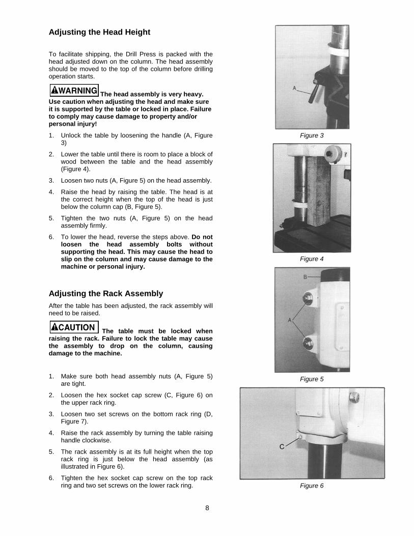
1. Unlock the table by loosening the handle (A, Figure 3)
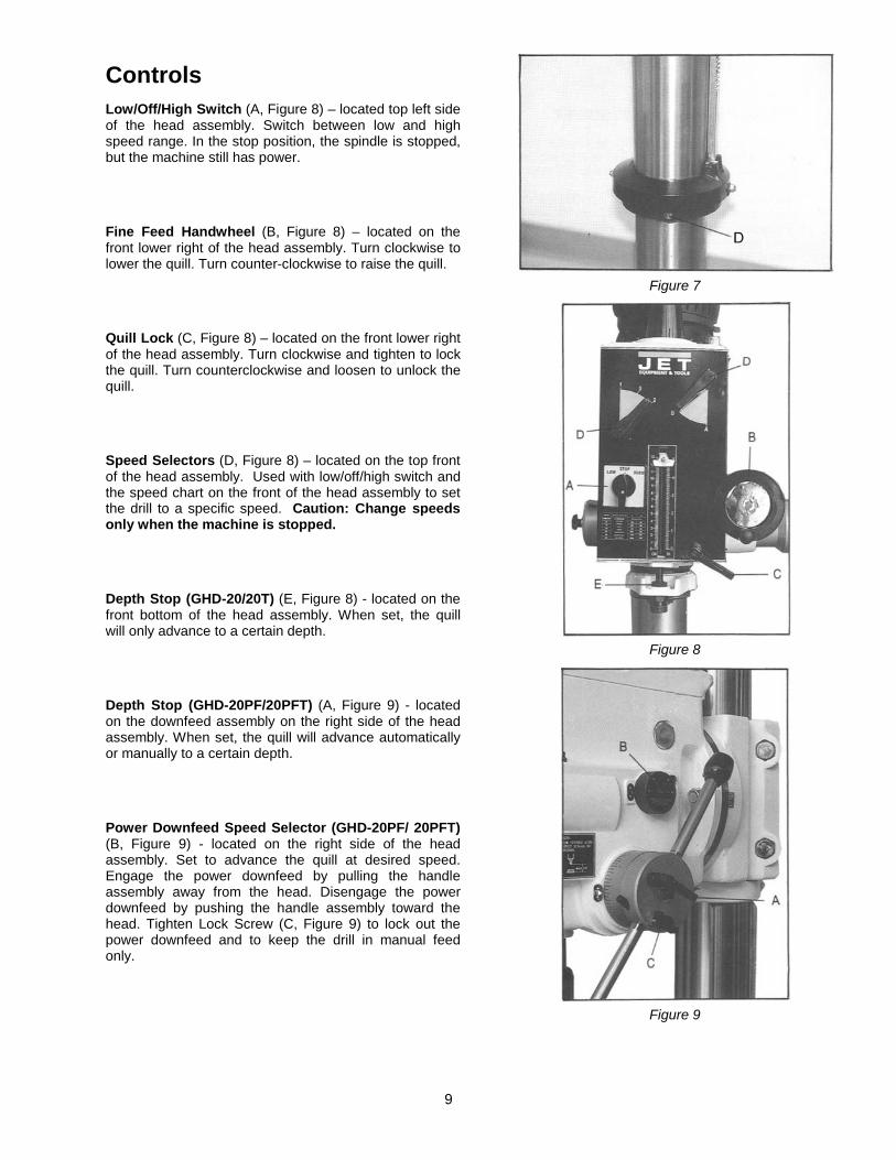
2. Lower the table until there is room to place a block of wood between the table and the head assembly (Figure 4).
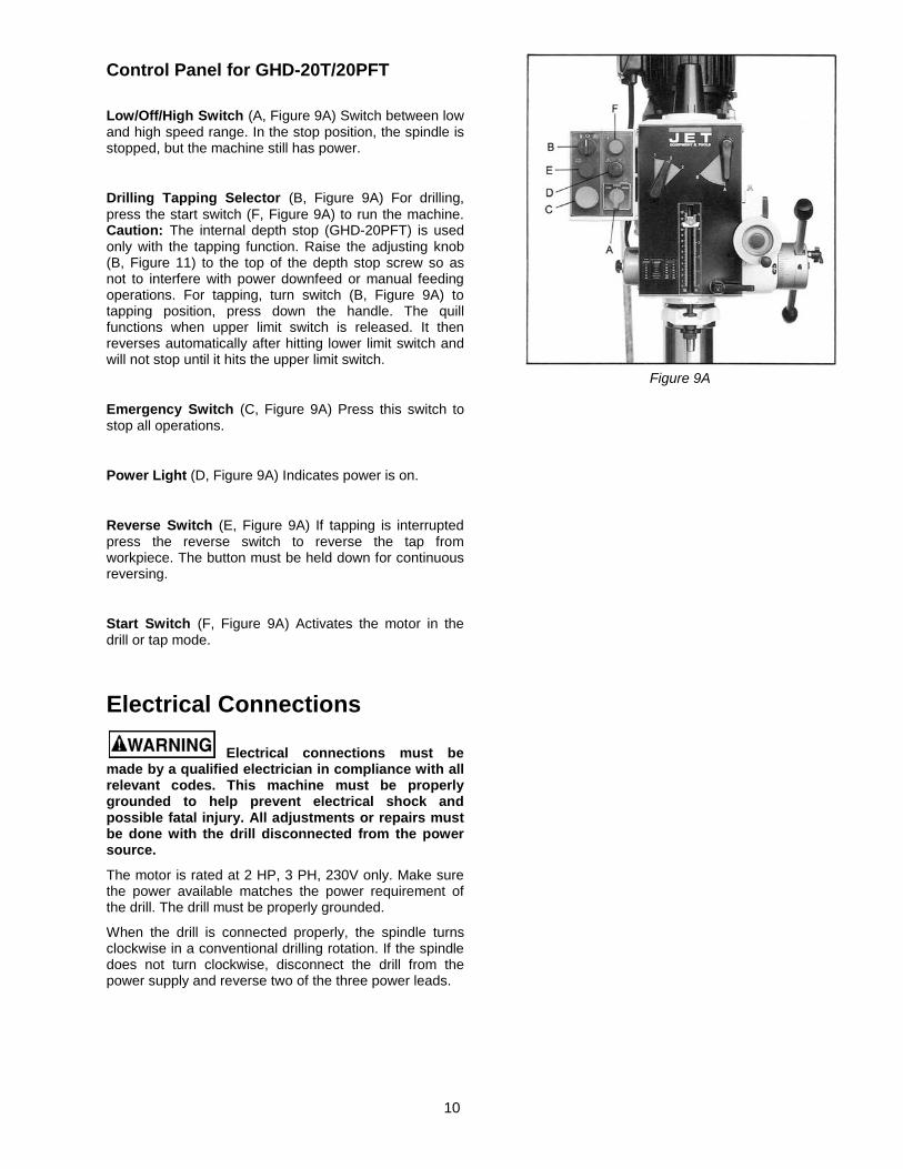
3. Loosen two nuts (A, Figure 5) on the head assembly.
4. Raise the head by raising the table. The head is at the correct height when the top of the head is just below the column cap (B, Figure 5).
5. Tighten the two nuts (A, Figure 5) on the head assembly firmly.
6. To lower the head, reverse the steps above. Do not loosen the head assembly bolts without supporting the head. This may cause the head to slip on the column and may cause damage to the machine or personal injury.
Adjusting the Rack Assembly After the table has been adjusted, the rack assembly will need to be raised.
The table must be locked when raising the rack. Failure to lock the table may cause the assembly to drop on the column, causing damage to the machine.
1. Make sure both head assembly nuts (A, Figure 5) are tight.
2. Loosen the hex socket cap screw (C, Figure 6) on the upper rack ring.
3. Loosen two set screws on the bottom rack ring (D, Figure 7).
4. Raise the rack assembly by turning the table raising handle clockwise.
5. The rack assembly is at its full height when the top rack ring is just below the head assembly (as illustrated in Figure 6).
6. Tighten the hex socket cap screw on the top rack ring and two set screws on the lower rack ring.
Figure 3
Figure 4
Figure 5
Figure 6
9
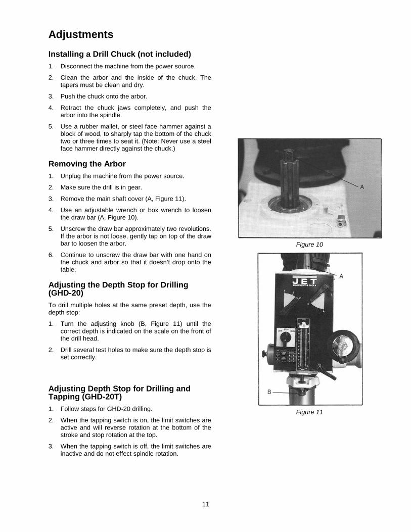
Controls Low/Off/High Switch (A, Figure 8) – located top left side of the head assembly. Switch between low and high speed range. In the stop position, the spindle is stopped, but the machine still has power.
Fine Feed Handwheel (B, Figure 8) – located on the front lower right of the head assembly. Turn clockwise to lower the quill. Turn counter-clockwise to raise the quill.
Quill Lock (C, Figure 8) – located on the front lower right of the head assembly. Turn clockwise and tighten to lock the quill. Turn counterclockwise and loosen to unlock the quill.
Speed Selectors (D, Figure 8) – located on the top front of the head assembly. Used with low/off/high switch and the speed chart on the front of the head assembly to set the drill to a specific speed. Caution: Change speeds only when the machine is stopped.
Depth Stop (GHD-20/20T) (E, Figure 8) - located on the front bottom of the head assembly. When set, the quill will only advance to a certain depth.
Depth Stop (GHD-20PF/20PFT) (A, Figure 9) - located on the downfeed assembly on the right side of the head assembly. When set, the quill will advance automatically or manually to a certain depth.
Power Downfeed Speed Selector (GHD-20PF/ 20PFT) (B, Figure 9) - located on the right side of the head assembly. Set to advance the quill at desired speed. Engage the power downfeed by pulling the handle assembly away from the head. Disengage the power downfeed by pushing the handle assembly toward the head. Tighten Lock Screw (C, Figure 9) to lock out the power downfeed and to keep the drill in manual feed only.
Figure 7
Figure 8
Figure 9
10
Control Panel for GHD-20T/20PFT Low/Off/High Switch (A, Figure 9A) Switch between low and high speed range. In the stop position, the spindle is stopped, but the machine still has power.
Drilling Tapping Selector (B, Figure 9A) For drilling, press the start switch (F, Figure 9A) to run the machine. Caution: The internal depth stop (GHD-20PFT) is used only with the tapping function. Raise the adjusting knob (B, Figure 11) to the top of the depth stop screw so as not to interfere with power downfeed or manual feeding operations. For tapping, turn switch (B, Figure 9A) to tapping position, press down the handle. The quill functions when upper limit switch is released. It then reverses automatically after hitting lower limit switch and will not stop until it hits the upper limit switch.
Emergency Switch (C, Figure 9A) Press this switch to stop all operations.
Power Light (D, Figure 9A) Indicates power is on.
Reverse Switch (E, Figure 9A) If tapping is interrupted press the reverse switch to reverse the tap from workpiece. The button must be held down for continuous reversing.
Start Switch (F, Figure 9A) Activates the motor in the drill or tap mode.
Electrical Connections
Electrical connections must be made by a qualified electrician in compliance with all relevant codes. This machine must be properly grounded to help prevent electrical shock and possible fatal injury. All adjustments or repairs must be done with the drill disconnected from the power source.
The motor is rated at 2 HP, 3 PH, 230V only. Make sure the power available matches the power requirement of the drill. The drill must be properly grounded.
When the drill is connected properly, the spindle turns clockwise in a conventional drilling rotation. If the spindle does not turn clockwise, disconnect the drill from the power supply and reverse two of the three power leads.
Figure 9A
11
Adjustments
Installing a Drill Chuck (not included) 1. Disconnect the machine from the power source.
2. Clean the arbor and the inside of the chuck. The tapers must be clean and dry.
3. Push the chuck onto the arbor.
4. Retract the chuck jaws completely, and push the arbor into the spindle.
5. Use a rubber mallet, or steel face hammer against a block of wood, to sharply tap the bottom of the chuck two or three times to seat it. (Note: Never use a steel face hammer directly against the chuck.)
Removing the Arbor 1. Unplug the machine from the power source.
2. Make sure the drill is in gear.
3. Remove the main shaft cover (A, Figure 11).
4. Use an adjustable wrench or box wrench to loosen the draw bar (A, Figure 10).
5. Unscrew the draw bar approximately two revolutions. If the arbor is not loose, gently tap on top of the draw bar to loosen the arbor.
6. Continue to unscrew the draw bar with one hand on the chuck and arbor so that it doesn’t drop onto the table.
Adjusting the Depth Stop for Drilling (GHD-20) To drill multiple holes at the same preset depth, use the depth stop:
1. Turn the adjusting knob (B, Figure 11) until the correct depth is indicated on the scale on the front of the drill head.
2. Drill several test holes to make sure the depth stop is set correctly.
Adjusting Depth Stop for Drilling and Tapping (GHD-20T) 1. Follow steps for GHD-20 drilling.
2. When the tapping switch is on, the limit switches are active and will reverse rotation at the bottom of the stroke and stop rotation at the top.
3. When the tapping switch is off, the limit switches are inactive and do not effect spindle rotation.
Figure 10
Figure 11

12
Adjusting the Depth Stop for Drilling (GHD-20PF) 1. Loosen the depth stop lock handle (A, Figure 12).
2. Manually advance the quill to the desired depth with one hand.
3. With the other hand, turn the depth stop scale (B, Figure 12) counter-clockwise to zero.
4. Tighten the depth stop lock handle (A, Figure 12). The depth stop will now stop the drill at the pre-determined setting.
Adjusting the Depth Stop for Drilling (GHD-20PFT) 1. Turn the adjusting knob (B, Figure 11) until full travel
is possible. Do not use this scale as a reference when drilling. This depth stop is for tapping only and should not interfere with drilling operations.
2. Follow steps for GHD-20PF drilling.
Adjusting the Depth Stop for Tapping (GHD-20PFT) 1. Loosen the depth stop lock handle (A, Figure 12) so
that it does not interfere with the internal depth stop located on the front of the drill head.
2. Adjust the front depth stop for the proper depth.
3. Manually advance the quill releasing the upper limit switch for tapping. This will start the motor. The quill will reverse directions upon triggering the lower limit switch.
4. Do not powerfeed and tap at the same time.
Changing Spindle Speeds To change spindle speeds:
1. Stop the drill by turning the low/stop/high switch to stop.
2. Adjust the levers (A, Figure 13) to the desired speed as indicated by the speed chart. Turning the spindle by hand will help the gear teeth mesh.
Figure 12
Figure 13
13
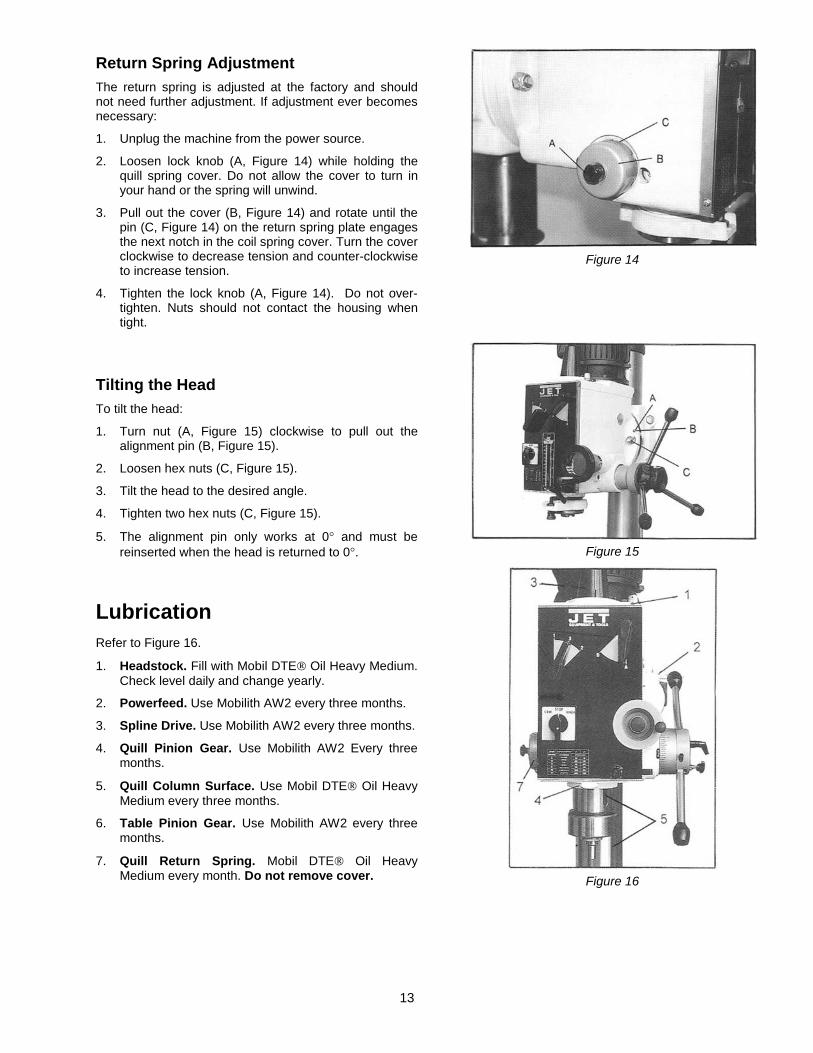
Return Spring Adjustment The return spring is adjusted at the factory and should not need further adjustment. If adjustment ever becomes necessary:
1. Unplug the machine from the power source.
2. Loosen lock knob (A, Figure 14) while holding the quill spring cover. Do not allow the cover to turn in your hand or the spring will unwind.
3. Pull out the cover (B, Figure 14) and rotate until the pin (C, Figure 14) on the return spring plate engages the next notch in the coil spring cover. Turn the cover clockwise to decrease tension and counter-clockwise to increase tension.
4. Tighten the lock knob (A, Figure 14). Do not over-tighten. Nuts should not contact the housing when tight.
Tilting the Head To tilt the head:
1. Turn nut (A, Figure 15) clockwise to pull out the alignment pin (B, Figure 15).
2. Loosen hex nuts (C, Figure 15).
3. Tilt the head to the desired angle.
4. Tighten two hex nuts (C, Figure 15).
5. The alignment pin only works at 0° and must be reinserted when the head is returned to 0°.
Lubrication Refer to Figure 16.
1. Headstock. Fill with Mobil DTE® Oil Heavy Medium. Check level daily and change yearly.
2. Powerfeed. Use Mobilith AW2 every three months.
3. Spline Drive. Use Mobilith AW2 every three months.
4. Quill Pinion Gear. Use Mobilith AW2 Every three months.
5. Quill Column Surface. Use Mobil DTE® Oil Heavy Medium every three months.
6. Table Pinion Gear. Use Mobilith AW2 every three months.
7. Quill Return Spring. Mobil DTE® Oil Heavy Medium every month. Do not remove cover.
Figure 14
Figure 15
Figure 16
14
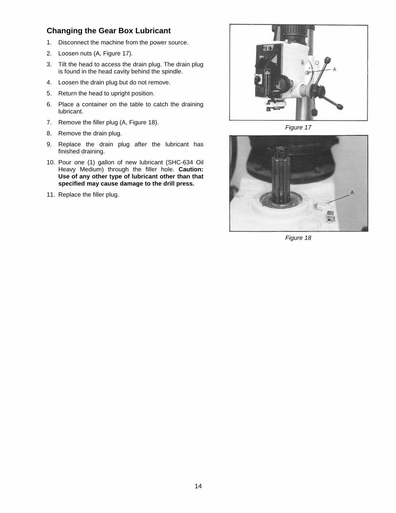
Changing the Gear Box Lubricant 1. Disconnect the machine from the power source.
2. Loosen nuts (A, Figure 17).
3. Tilt the head to access the drain plug. The drain plug is found in the head cavity behind the spindle.
4. Loosen the drain plug but do not remove.
5. Return the head to upright position.
6. Place a container on the table to catch the draining lubricant.
7. Remove the filler plug (A, Figure 18).
8. Remove the drain plug.
9. Replace the drain plug after the lubricant has finished draining.
10. Pour one (1) gallon of new lubricant (SHC-634 Oil Heavy Medium) through the filler hole. Caution: Use of any other type of lubricant other than that specified may cause damage to the drill press.
11. Replace the filler plug.
Figure 17
Figure 18
15
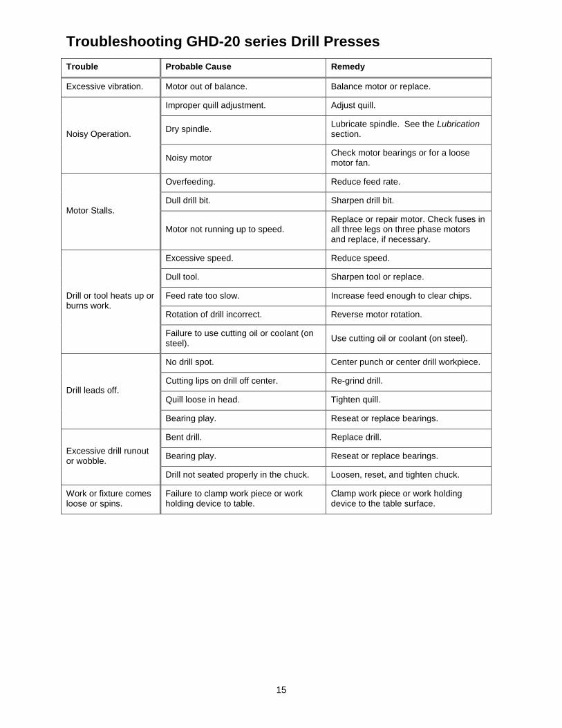
Troubleshooting GHD-20 series Drill Presses Trouble Probable Cause Remedy
Excessive vibration. Motor out of balance. Balance motor or replace.
Noisy Operation.
Improper quill adjustment. Adjust quill.
Dry spindle. Lubricate spindle. See the Lubrication section.
Noisy motor Check motor bearings or for a loose motor fan.
Motor Stalls.
Overfeeding. Reduce feed rate.
Dull drill bit. Sharpen drill bit.
Motor not running up to speed. Replace or repair motor. Check fuses in all three legs on three phase motors and replace, if necessary.
Drill or tool heats up or burns work.
Excessive speed. Reduce speed.
Dull tool. Sharpen tool or replace.
Feed rate too slow. Increase feed enough to clear chips.
Rotation of drill incorrect. Reverse motor rotation.
Failure to use cutting oil or coolant (on steel). Use cutting oil or coolant (on steel).
Drill leads off.
No drill spot. Center punch or center drill workpiece.
Cutting lips on drill off center. Re-grind drill.
Quill loose in head. Tighten quill.
Bearing play. Reseat or replace bearings.
Excessive drill runout or wobble.
Bent drill. Replace drill.
Bearing play. Reseat or replace bearings.
Drill not seated properly in the chuck. Loosen, reset, and tighten chuck.
Work or fixture comes loose or spins.
Failure to clamp work piece or work holding device to table.
Clamp work piece or work holding device to the table surface.

16
Replacement Parts Replacement parts are listed on the following pages. To order parts or reach our service department, call 1-800-274-6848 Monday through Friday, 8:00 a.m. to 5:00 p.m. CST. Having the Model Number and Serial Number of your machine available when you call will allow us to serve you quickly and accurately.
Non-proprietary parts, such as fasteners, can be found at local hardware stores, or may be ordered from JET.
Some parts are shown for reference only, and may not be available individually.
17
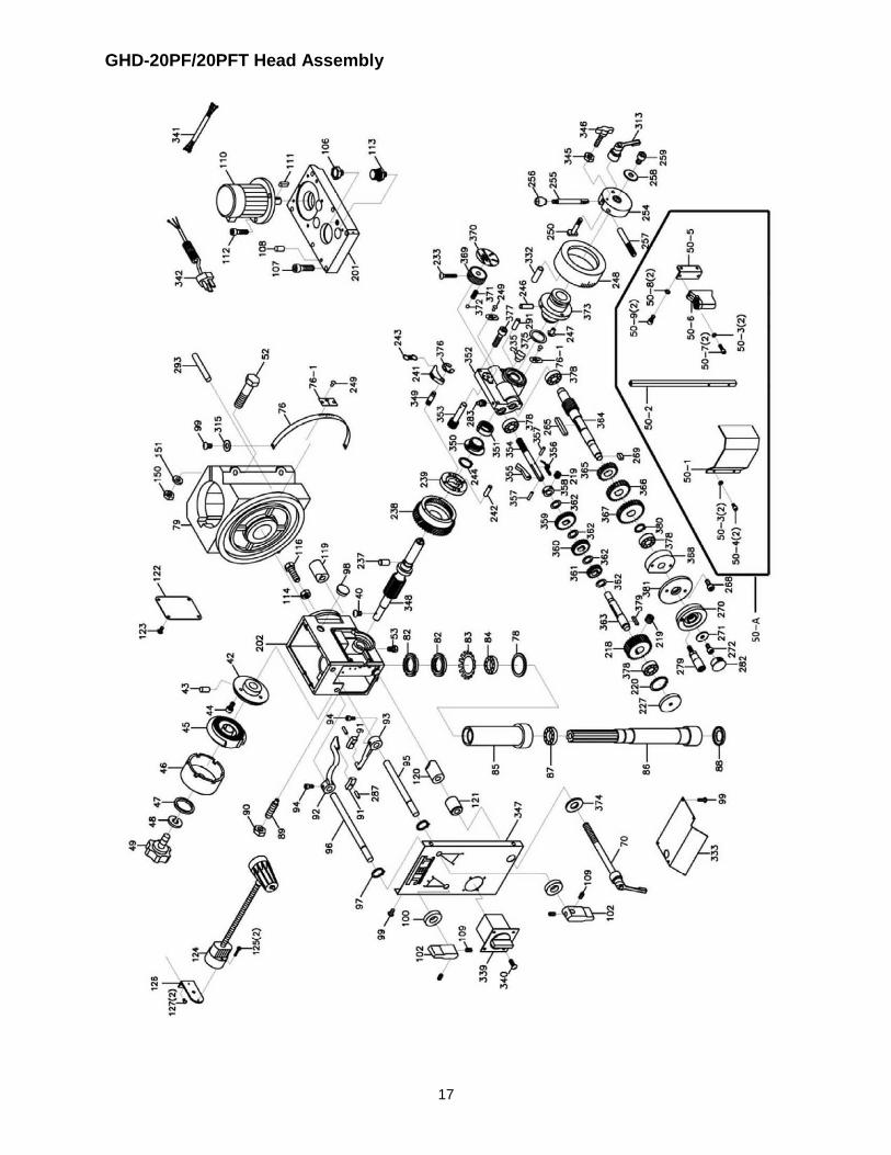
GHD-20PF/20PFT Head Assembly
18
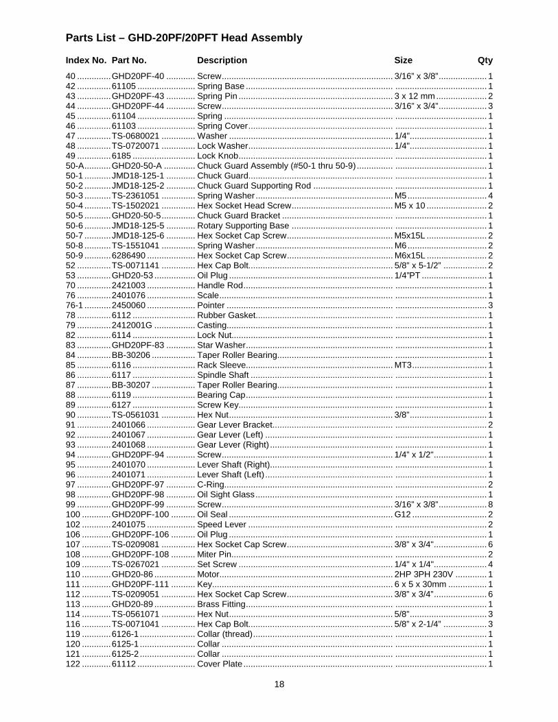
Parts List – GHD-20PF/20PFT Head Assembly
Index No. Part No. Description Size Qty 40 .............. GHD20PF-40 ............ Screw ....................................................................... 3/16” x 3/8” .................... 1 42 .............. 61105 ........................ Spring Base ............................................................. ...................................... 1 43 .............. GHD20PF-43 ............ Spring Pin ................................................................ 3 x 12 mm ..................... 2 44 .............. GHD20PF-44 ............ Screw ....................................................................... 3/16” x 3/4” .................... 3 45 .............. 61104 ........................ Spring ...................................................................... ...................................... 1 46 .............. 61103 ........................ Spring Cover ............................................................ ...................................... 1 47 .............. TS-0680021 .............. Washer .................................................................... 1/4" ................................ 1 48 .............. TS-0720071 .............. Lock Washer ............................................................ 1/4" ................................ 1 49 .............. 6185 .......................... Lock Knob ................................................................ ...................................... 1 50-A ........... GHD20-50-A ............. Chuck Guard Assembly (#50-1 thru 50-9) ............... ...................................... 1 50-1 ........... JMD18-125-1 ............ Chuck Guard............................................................ ...................................... 1 50-2 ........... JMD18-125-2 ............ Chuck Guard Supporting Rod ................................. ...................................... 1 50-3 ........... TS-2361051 .............. Spring Washer ......................................................... M5 ................................. 4 50-4 ........... TS-1502021 .............. Hex Socket Head Screw .......................................... M5 x 10 ......................... 2 50-5 ........... GHD20-50-5 .............. Chuck Guard Bracket .............................................. ...................................... 1 50-6 ........... JMD18-125-5 ............ Rotary Supporting Base .......................................... ...................................... 1 50-7 ........... JMD18-125-6 ............ Hex Socket Cap Screw ............................................ M5x15L ......................... 2 50-8 ........... TS-1551041 .............. Spring Washer ......................................................... M6 ................................. 2 50-9 ........... 6286490 .................... Hex Socket Cap Screw ............................................ M6x15L ......................... 2 52 .............. TS-0071141 .............. Hex Cap Bolt............................................................ 5/8” x 5-1/2” .................. 2 53 .............. GHD20-53 ................. Oil Plug .................................................................... 1/4”PT ........................... 1 70 .............. 2421003 .................... Handle Rod .............................................................. ...................................... 1 76 .............. 2401076 .................... Scale ........................................................................ ...................................... 1 76-1 ........... 2450060 .................... Pointer ..................................................................... ...................................... 3 78 .............. 6112 .......................... Rubber Gasket......................................................... ...................................... 1 79 .............. 2412001G ................. Casting..................................................................... ...................................... 1 82 .............. 6114 .......................... Lock Nut................................................................... ...................................... 1 83 .............. GHD20PF-83 ............ Star Washer ............................................................. ...................................... 1 84 .............. BB-30206 .................. Taper Roller Bearing................................................ ...................................... 1 85 .............. 6116 .......................... Rack Sleeve............................................................. MT3 ............................... 1 86 .............. 6117 .......................... Spindle Shaft ........................................................... ...................................... 1 87 .............. BB-30207 .................. Taper Roller Bearing................................................ ...................................... 1 88 .............. 6119 .......................... Bearing Cap ............................................................. ...................................... 1 89 .............. 6127 .......................... Screw Key................................................................ ...................................... 1 90 .............. TS-0561031 .............. Hex Nut .................................................................... 3/8” ................................ 1 91 .............. 2401066 .................... Gear Lever Bracket.................................................. ...................................... 2 92 .............. 2401067 .................... Gear Lever (Left) ..................................................... ...................................... 1 93 .............. 2401068 .................... Gear Lever (Right) ................................................... ...................................... 1 94 .............. GHD20PF-94 ............ Screw ....................................................................... 1/4” x 1/2" ...................... 1 95 .............. 2401070 .................... Lever Shaft (Right)................................................... ...................................... 1 96 .............. 2401071 .................... Lever Shaft (Left) ..................................................... ...................................... 1 97 .............. GHD20PF-97 ............ C-Ring...................................................................... ...................................... 2 98 .............. GHD20PF-98 ............ Oil Sight Glass ......................................................... ...................................... 1 99 .............. GHD20PF-99 ............ Screw ....................................................................... 3/16” x 3/8” .................... 8 100 ............ GHD20PF-100 .......... Oil Seal .................................................................... G12 ............................... 2 102 ............ 2401075 .................... Speed Lever ............................................................ ...................................... 2 106 ............ GHD20PF-106 .......... Oil Plug .................................................................... ...................................... 1 107 ............ TS-0209081 .............. Hex Socket Cap Screw ............................................ 3/8” x 3/4" ...................... 6 108 ............ GHD20PF-108 .......... Miter Pin................................................................... ...................................... 2 109 ............ TS-0267021 .............. Set Screw ................................................................ 1/4" x 1/4"...................... 4 110 ............ GHD20-86 ................. Motor........................................................................ 2HP 3PH 230V ............. 1 111 ............ GHD20PF-111 .......... Key........................................................................... 6 x 5 x 30mm ................ 1 112 ............ TS-0209051 .............. Hex Socket Cap Screw ............................................ 3/8” x 3/4” ...................... 6 113 ............ GHD20-89 ................. Brass Fitting ............................................................. ...................................... 1 114 ............ TS-0561071 .............. Hex Nut .................................................................... 5/8” ................................ 3 116 ............ TS-0071041 .............. Hex Cap Bolt............................................................ 5/8” x 2-1/4” .................. 3 119 ............ 6126-1 ....................... Collar (thread) .......................................................... ...................................... 1 120 ............ 6125-1 ....................... Collar ....................................................................... ...................................... 1 121 ............ 6125-2 ....................... Collar ....................................................................... ...................................... 1 122 ............ 61112 ........................ Cover Plate .............................................................. ...................................... 1
19
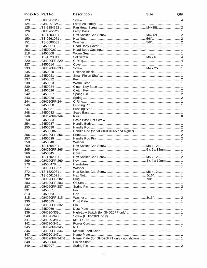
Index No. Part No. Description Size Qty 123 ............ GHD20-123 ............... Screw ....................................................................... ...................................... 4 124 ............ GHD20-124 ............... Lamp Assembly ....................................................... ...................................... 1 125 ............ TS-2284352 .............. Pan Head Screw ...................................................... M4x35L ......................... 2 126 ............ GHD20-126 ............... Lamp Base .............................................................. ...................................... 1 127 ............ TS-1503031 .............. Hex Socket Cap Screw ............................................ M6x12L ......................... 2 150 ............ TS-0561071 .............. Hex Nut .................................................................... 5/8” ................................ 2 151 ............ TS-0680081 .............. Washer .................................................................... 5/8” ................................ 2 201 ............ 2450001G ................. Head Body Cover .................................................... ...................................... 1 202 ............ 2450002G ................. Head Body Casting .................................................. ...................................... 1 218 ............ 2450008 .................... Worm Gear .............................................................. ...................................... 1 219 ............ TS-1523011 .............. Set Screw ................................................................ M6 x 6 ........................... 4 220 ............ GHD20PF-220 .......... C-Ring...................................................................... ...................................... 4 227 ............ 2450014 .................... Cover ....................................................................... ...................................... 1 233 ............ GHD20PF-233 .......... Screw ....................................................................... M4 x 25 ......................... 1 235 ............ 2450020 .................... Release Block .......................................................... ...................................... 1 236 ............ 2450021 .................... Small Pinion Shaft ................................................... ...................................... 1 237 ............ 2450022 .................... Key........................................................................... ...................................... 2 238 ............ 2450023 .................... Worm Gear .............................................................. ...................................... 1 239 ............ 2450024 .................... Clutch Key Base ...................................................... ...................................... 1 241 ............ 2450026 .................... Clutch Key ............................................................... ...................................... 2 242 ............ 2450027 .................... Spring Pin ................................................................ ...................................... 2 243 ............ 2450028 .................... Spring ...................................................................... ...................................... 2 244 ............ GHD20PF-244 .......... C-Ring...................................................................... ...................................... 1 246 ............ 2450030 .................... Bushing Pin ............................................................. ...................................... 1 247 ............ 2450031 .................... Bushing Stop ........................................................... ...................................... 1 248 ............ 2450032 .................... Scale Base .............................................................. ...................................... 1 249 ............ GHD20PF-249 .......... Rivet......................................................................... ...................................... 8 250 ............ 2450033 .................... Scale Base Set Screw ............................................. ...................................... 1 254 ............ 2450037 .................... Handle Body ............................................................ ...................................... 1 255 ............ 2450038 .................... Handle Rod .............................................................. ...................................... 2 .................. 2450038N .................. Handle Rod (serial #16031665 and higher) ............. ...................................... 2 256 ............ GHD20PF-256 .......... Knob ........................................................................ ...................................... 2 257 ............ 2450039 .................... Handle Rod Pin ....................................................... ...................................... 2 258 ............ 2450040 .................... Washer .................................................................... ...................................... 1 259 ............ TS-1504021 .............. Hex Socket Cap Screw ............................................ M8 x 12 ......................... 1 265 ............ GHD20PF-265 .......... Key........................................................................... 5 x 5 x 32mm ................ 1 266 ............ 2450045 .................... Cover ....................................................................... ...................................... 1 268 ............ TS-1502031 .............. Hex Socket Cap Screw ............................................ M5 x 12 ......................... 2 269 ............ GHD20PF-269 .......... Key........................................................................... 4 x 4 x 10mm ................ 1 270 ............ 24500470 .................. Handwheel ............................................................... ...................................... 1 271 ............ GHD20PF-271 .......... Washer .................................................................... ...................................... 1 272 ............ TS-1523031 .............. Hex Socket Cap Screw ............................................ M6 x 12 ......................... 1 279 ............ TS-0561021 .............. Hex Nut .................................................................... 5/16” .............................. 1 282 ............ GHD20PF-282 .......... Plug.......................................................................... 7/8” ................................ 1 283 ............ GHD20PF-283 .......... Oil Seal .................................................................... ...................................... 1 287 ............ GHD20PF-287 .......... Spring Pin ................................................................ ...................................... 2 291 ............ 2450051 .................... Pin............................................................................ ...................................... 1 313 ............ 2450063 .................... Grip .......................................................................... ...................................... 1 315 ............ GHD20PF-315 .......... Washer .................................................................... 3/16” .............................. 2 330 ............ 2401085 .................... Dust Plate ................................................................ ...................................... 1 332 ............ GHD20PF-332 .......... Pin............................................................................ ...................................... 1 333 ............ 2450069 .................... Dust Plate ................................................................ ...................................... 1 339 ............ GHD20-339 ............... High-Low Switch (for GHD20PF only) ..................... ...................................... 1 340 ............ GHD20-340 ............... Screw (GHD-20PF only) .......................................... ...................................... 1 341 ............ GHD20-341 ............... Motor Cord ............................................................... ...................................... 1 342 ............ GHD20-342 ............... Power Cord .............................................................. ...................................... 1 345 ............ GHD20PF-345 .......... Nut ........................................................................... ...................................... 1 346 ............ GHD20PF-346 .......... Manual Feed Knob .................................................. ...................................... 1 347 ............ GHD20-347 ............... Name Plate .............................................................. ...................................... 1 347-1 ......... GHD20PF-347-1 ....... Name Plate (for GHD20PFT only - not shown) ....... ...................................... 1 348 ............ 2450086A .................. Pinion Shaft ............................................................. ...................................... 1 349 ............ 2450097 .................... Spring Pin ................................................................ ...................................... 2
20
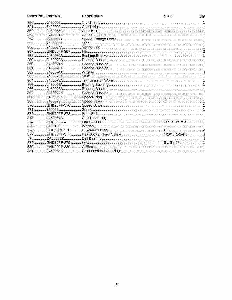
Index No. Part No. Description Size Qty 350 ............ 2450096 .................... Clutch Screw............................................................ ...................................... 1 351 ............ 2450095 .................... Clutch Nut ................................................................ ...................................... 1 352 ............ 2450068G ................. Gear Box.................................................................. ...................................... 1 353 ............ 2450081A .................. Gear Shaft ............................................................... ...................................... 1 354 ............ 2450082A .................. Speed Change Lever ............................................... ...................................... 1 355 ............ 2450083A .................. Stop ......................................................................... ...................................... 1 356 ............ 2450084A .................. Spring Leaf .............................................................. ...................................... 1 357 ............ GHD20PF-357 .......... Pin............................................................................ ...................................... 2 358 ............ 2450089A .................. Bushing Bracket ...................................................... ...................................... 1 359 ............ 2450072A .................. Bearing Bushing ...................................................... ...................................... 1 360 ............ 2450071A .................. Bearing Bushing ...................................................... ...................................... 1 361 ............ 2450070A .................. Bearing Bushing ...................................................... ...................................... 1 362 ............ 2450074A .................. Washer .................................................................... ...................................... 4 363 ............ 2450073A .................. Shaft ........................................................................ ...................................... 1 364 ............ 2450078A .................. Transmission Worm ................................................. ...................................... 1 365 ............ 2450075A .................. Bearing Bushing ...................................................... ...................................... 1 366 ............ 2450076A .................. Bearing Bushing ...................................................... ...................................... 1 367 ............ 2450077A .................. Bearing Bushing ...................................................... ...................................... 1 368 ............ 2450085A .................. Spacer Ring ............................................................. ...................................... 1 369 ............ 2450079 .................... Speed Lever ............................................................ ...................................... 1 370 ............ GHD20PF-370 .......... Speed Scale ............................................................ ...................................... 1 371 ............ 290089 ...................... Spring ...................................................................... ...................................... 1 372 ............ GHD20PF-372 .......... Steel Ball.................................................................. ...................................... 1 373 ............ 2450087A .................. Clutch Bushing ........................................................ ...................................... 1 374 ............ GHD20-374 ............... Flat Washer ............................................................. 1/2” x 7/8” x 2” ............... 1 375 ............ 2450100 .................... Washer .................................................................... ...................................... 1 376 ............ GHD20PF-376 .......... E-Retainer Ring ....................................................... E5 ................................. 2 377 ............ GHD20PF-377 .......... Hex Socket Head Screw .......................................... 5/16” x 1-1/4”L .............. 4 378 ............ CA6003ZZ ................. Ball Bearing ............................................................. ...................................... 4 379 ............ GHD20PF-379 .......... Key........................................................................... 5 x 5 x 28L mm ............. 1 380 ............ GHD20PF-380 .......... C-Ring...................................................................... ...................................... 1 381 ............ 2450088A .................. Graduated Bottom Ring ........................................... ...................................... 1
21
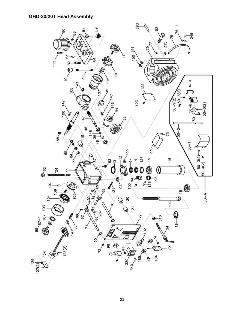
GHD-20/20T Head Assembly
22
Parts List – GHD-20/20T Head Assembly
Index No. Part No. Description Size Qty 11 .............. 2401011G ................. Head Casting ........................................................... ...................................... 1 12 .............. 6112 .......................... Rubber Gasket......................................................... ...................................... 1 13 .............. 6513 .......................... Feed Base ............................................................... ...................................... 1 14 .............. 6114 .......................... Lock Nut................................................................... ...................................... 2 15 .............. BB-30206 .................. Taper Roller Bearing................................................ ...................................... 1 16 .............. 6116 .......................... Rack Sleeve............................................................. MT3 ............................... 1 17 .............. 6117 .......................... Spindle Shaft ........................................................... MT3 ............................... 1 18 .............. BB-30207 .................. Taper Roller Bearing................................................ ...................................... 1 19 .............. 6119 .......................... Bearing Cap ............................................................. ...................................... 1 24 .............. 2421003 .................... Handle Rod .............................................................. ...................................... 1 27 .............. 6127 .......................... Screw Key................................................................ ...................................... 1 35 .............. 6135 .......................... Bearing Spacer ........................................................ ...................................... 1 39 .............. 6139 .......................... Handle Rod .............................................................. ...................................... 3 .................. 6139N ........................ Handle Rod (serial #16031665 and higher) ............. ...................................... 3 40 .............. 290086 ...................... Knob ........................................................................ ...................................... 3 44 .............. 6144 .......................... Micro Adjusting Indicator ......................................... ...................................... 1 45 .............. 6145 .......................... Worm Cover............................................................. ...................................... 1 46 .............. BB-6202Z .................. Ball Bearing ............................................................. ...................................... 2 47 .............. 6147 .......................... Worm Shaft .............................................................. ...................................... 1 50-A ........... GHD20-50-A ............. Chuck Guard Assembly (#50-1 thru 50-9) ............... ...................................... 1 50-1 ........... JMD18-125-1 ............ Chuck Guard............................................................ ...................................... 1 50-2 ........... JMD18-125-2 ............ Chuck Guard Supporting Rod ................................. ...................................... 1 50-3 ........... TS-2361051 .............. Spring Washer ......................................................... M5 ................................. 4 50-4 ........... TS-1502021 .............. Hex Socket Head Screw .......................................... M5 x 10 ......................... 2 50-5 ........... GHD20-50-5 .............. Chuck Guard Bracket .............................................. ...................................... 1 50-6 ........... JMD18-125-5 ............ Rotary Supporting Base .......................................... ...................................... 1 50-7 ........... JMD18-125-6 ............ Hex Socket Cap Screw ............................................ M5x15L ......................... 2 50-8 ........... TS-1551041 .............. Spring Washer ......................................................... M6 ................................. 2 50-9 ........... 6286490 .................... Hex Socket Cap Screw ............................................ M6x15L ......................... 2 52 .............. TS-0071141 .............. Hex Cap Bolt............................................................ 5/8” x 5-1/2” .................. 2 53 .............. GHD20-53 ................. Oil Plug .................................................................... ...................................... 1 54 .............. GHD20-54 ................. Threaded Rod .......................................................... ...................................... 1 62 .............. 6142-2 ....................... Head Wheel ............................................................. ...................................... 1 63 .............. TS-0561071 .............. Hex Nut .................................................................... 5/8” ................................ 3 64 .............. TS-0680081 .............. Washer .................................................................... ...................................... 2 65 .............. TS-0071041 .............. Hex Screw ............................................................... 5/8” x 2-1/4” .................. 3 66 .............. 2401066 .................... Gear Lever Bracket.................................................. ...................................... 2 67 .............. 2401067 .................... Gear Lever (Left) ..................................................... ...................................... 1 68 .............. 2401068 .................... Gear Lever (Right) ................................................... ...................................... 1 69 .............. GHD20-69 ................. Screw ....................................................................... 1/4” x 1/2" ...................... 2 70 .............. 2401070 .................... Lever Shaft (Right)................................................... ...................................... 1 71 .............. 2401071 .................... Lever Shaft (Left) ..................................................... ...................................... 1 72 .............. 2401072 .................... Name Plate (for GHD-20 only)................................. ...................................... 1 .................. GHD20T-72 ............... Name Plate (for GHD20T only not - shown) ............ ...................................... 1 73 .............. GHD20-73 ................. Screw ....................................................................... 3/16” x 3/8” .................... 8 74 .............. TS-0267021 .............. Set Screw ................................................................ 1/4" x 1/4"...................... 8 75 .............. 2401075 .................... Speed Lever ............................................................ ...................................... 2 76 .............. GHD20-76 ................. Scale ........................................................................ ...................................... 1 76-1 ........... 2401076-1 ................. Pointer ..................................................................... ...................................... 1 77 .............. GHD20-77 ................. Screw ....................................................................... ...................................... 2 79 .............. 2412001G ................. Block ........................................................................ ...................................... 1 81 .............. GHD20-81 ................. Oil Plug .................................................................... ...................................... 1 82 .............. TS-0209061 .............. Hex Socket Cap Screw ............................................ 3/8” x 3/4” ...................... 6 83 .............. GHD20-83 ................. Miter Pin................................................................... ...................................... 2 84 .............. 2401084G ................. Cover ....................................................................... ...................................... 1 85 .............. 6185 .......................... Lock Handle ............................................................. ...................................... 1 86 .............. GHD20-86 ................. Motor........................................................................ 2HP 3PH 230V ............. 1 87 .............. GHD20-87 ................. Oil Sight Glass ......................................................... ...................................... 1 88 .............. GHD20-88 ................. Key........................................................................... 6 x 6 x 30mm ................ 1 89 .............. GHD20-89 ................. Brass Fitting ............................................................. ...................................... 1
23
Index No. Part No. Description Size Qty 90 .............. GHD20-90 ................. C-Ring...................................................................... ...................................... 2 92 .............. 6192 .......................... Block ........................................................................ ...................................... 1 93 .............. 6193 .......................... Nut ........................................................................... ...................................... 1 94 .............. 6194 .......................... Support Base ........................................................... ...................................... 1 95 .............. 6195 .......................... Knob Assembly ........................................................ ...................................... 1 96 .............. GHD20-96 ................. Oil Seal .................................................................... ...................................... 2 101 ............ 61101 ........................ Bracket..................................................................... ...................................... 1 102 ............ 61102 ........................ Limit Plate ................................................................ ...................................... 1 103 ............ 61103 ........................ Spring Cover ............................................................ ...................................... 1 104 ............ 61104 ........................ Spring ...................................................................... ...................................... 1 105 ............ 61105 ........................ Spring Base ............................................................. ...................................... 1 106 ............ 61106 ........................ Pinion Shaft ............................................................. ...................................... 1 107 ............ 61107 ........................ Worm Gear .............................................................. ...................................... 1 108 ............ 61108G ..................... Feed Cover .............................................................. ...................................... 1 110 ............ 61110 ........................ Spring Base ............................................................. ...................................... 1 111 ............ 6138 .......................... Lock Bolt w/ Knob .................................................... ...................................... 1 112 ............ TS-0209051 .............. Hex Socket Cap Screw ............................................ 3/8” x 1” ......................... 3 115 ............ 61115 ........................ Spring ...................................................................... ...................................... 1 119 ............ 6126-1 ....................... Collar (thread) .......................................................... ...................................... 1 120 ............ 6125-1 ....................... Collar ....................................................................... ...................................... 1 121 ............ 6125-2 ....................... Collar ....................................................................... ...................................... 1 122 ............ 61112G ..................... Cover ....................................................................... ...................................... 1 123 ............ GHD20-123 ............... Screw ....................................................................... ...................................... 4 124 ............ GHD20-124 ............... Lamp Assembly ....................................................... ...................................... 1 124-1 ......... GHD20-124-1 ............ Lamp Assembly (Independent power for GHD-20) . ...................................... 1 125 ............ TS-2284352 .............. Pan Head Screw ...................................................... M4x35L ......................... 2 126 ............ GHD20-126 ............... Lamp Base .............................................................. ...................................... 1 127 ............ TS-1503031 .............. Hex Socket Cap Screw ............................................ M6x12L ......................... 2 130 ............ TS-1501021 .............. Hex Socket Cap Screw ............................................ M4 x 8 ........................... 1 134 ............ TS-005091 ................ Hex Cap Bolt............................................................ 1/4" x 2” ......................... 1 135 ............ TS-0561011 .............. Hex Nut .................................................................... 1/4" ................................ 1 136 ............ 6195 .......................... Spring Pin ................................................................ ...................................... 1 137 ............ GHD20-137 ............... Star Washer ............................................................. ...................................... 1 139 ............ GHD20-139 ............... Screw ....................................................................... 3/16” x 3/4” .................... 3 140 ............ GHD20-140 ............... Spring Pin ................................................................ ...................................... 1 141 ............ TS-0561031 .............. Hex Nut .................................................................... 3/8” ................................ 1 142 ............ GHD20-142 ............... Key........................................................................... 7 x 7 x 20 ...................... 1 143 ............ TS-0208021 .............. Hex Socket Cap Screw ............................................ 5/16” x 1/2" .................... 2 145 ............ TS-0270021 .............. Set Screw ................................................................ 5/16” x 5/16” .................. 1 146 ............ TS-0267021 .............. Set Screw ................................................................ 1/4” x 1/4" ...................... 1 147 ............ GHD20-147 ............... Hex Socket Cap Screw ............................................ 3/16” x 7/16” .................. 2 148 ............ GHD20-148 ............... C-Ring...................................................................... ...................................... 1 150 ............ TS-0561071 .............. Hex Nut .................................................................... 5/8” ................................ 2 151 ............ TS-0680081 .............. Washer .................................................................... 5/8” ................................ 2 184 ............ GHD20-184 ............... Screw ....................................................................... 5/32” x 1/4" .................... 1 185 ............ GHD20-185 ............... Washer .................................................................... 1/4" ................................ 1 187 ............ TS-0680021 .............. Washer .................................................................... 1/4" ................................ 1 187-1 ......... TS-0720071 .............. Lock Washer ............................................................ 1/4" ................................ 1 188 ............ GHD20-188 ............... Screw ....................................................................... 3/16” x 3/8” .................... 1 249 ............ GHD20-249 ............... Rivet......................................................................... ...................................... 2 287 ............ GHD20-287 ............... Spring Pin ................................................................ ...................................... 2 330 ............ 2401085 .................... Dust Plate ................................................................ ...................................... 1 339 ............ GHD20-339 ............... Switch ...................................................................... ...................................... 1 340 ............ GHD20-340 ............... Screw ....................................................................... ...................................... 2 341 ............ GHD20-341 ............... Motor Cord ............................................................... ...................................... 1 342 ............ GHD20-342 ............... Power Cord .............................................................. ...................................... 1
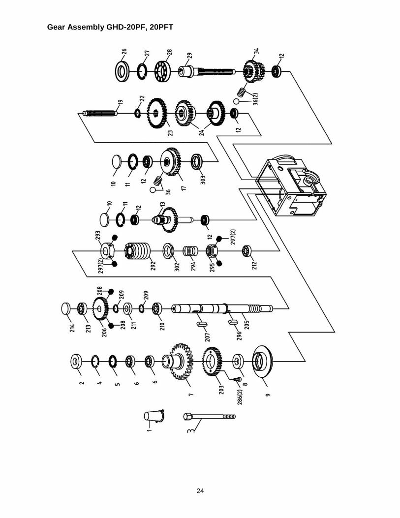
24
Gear Assembly GHD-20PF, 20PFT
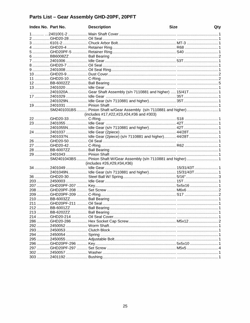
25
Parts List – Gear Assembly GHD-20PF, 20PFT
Index No. Part No. Description Size Qty 1….…... …2401001-2 .................. Main Shaft Cover ..................................................... ...................................... 1 2 ................ GHD20-28 ................. Oil Seal .................................................................... ...................................... 1 3 ................ 6101-2 ....................... Chuck Arbor Bolt...................................................... MT-3 ............................. 1 4 ................ GHD20-4 ................... Retainer Ring ........................................................... R68 ............................... 1 5 ................ GHD20PF-5 .............. Retainer Ring ........................................................... S40 ............................... 1 6 ................ BB6008ZZ ................. Ball Bearing ............................................................. ...................................... 2 7 ................ 2401006 .................... Idle Gear .................................................................. 53T ................................ 1 8 ................ GHD20-7 ................... Oil Seal .................................................................... ...................................... 1 9 ................ 2401008 .................... Oil Seal Ring ............................................................ ...................................... 1 10 .............. GHD20-9 ................... Dust Cover ............................................................... ...................................... 2 11 .............. GHD20-10 ................. C-Ring...................................................................... ...................................... 2 12 .............. BB-6002ZZ ................ Ball Bearing ............................................................. ...................................... 5 13 .............. 2401020 .................... Idle Gear .................................................................. ...................................... 1 .................. 2401020A .................. Gear Shaft Assembly (s/n 7110881 and higher) ..... 15/41T ........................... 1 17 .............. 2401029 .................... Idle Gear ................................................................. 35T ................................ 1 .................. 2401029N .................. Idle Gear (s/n 7110881 and higher) ......................... 35T ................................ 1 19 .............. 2401031 .................... Pinion Shaft ............................................................. ...................................... 1 .................. SM2401031BS .......... Pinion Shaft w/Gear Assembly (s/n 7110881 and higher) ............................. 1 (includes #17,#22,#23,#24,#36 and #303) 22 .............. GHD20-33 ................. C-Ring...................................................................... S18 ............................... 1 23 .............. 2401055 .................... Idle Gear ................................................................. 42T ................................ 1 .................. 2401055N .................. Idle Gear (s/n 7110881 and higher) ......................... 42T ................................ 1 24 .............. 2401037 .................... Idle Gear (2piece) .................................................... 44/28T ........................... 1 .................. 2401037N .................. Idle Gear (2piece) (s/n 7110881 and higher) ........... 44/28T ........................... 1 26 .............. GHD20-50 ................. Oil Seal .................................................................... ...................................... 1 27 .............. GHD20-42 ................. C-Ring...................................................................... R62 ............................... 1 28 .............. BB-6007ZZ ................ Ball Bearing ............................................................. ...................................... 1 29 .............. 2401043 .................... Pinion Shaft ............................................................. ...................................... 1 .................. SM2401043BS .......... Pinion Shaft W/Gear Assembly (s/n 7110881 and higher) ............................. 1 (includes #26,#29,#34,#36) 34 .............. 2401049 .................... Idle Gear .................................................................. 15/31/43T ...................... 1 .................. 2401049N .................. Idle Gear (s/n 7110881 and higher) ......................... 15/31/43T ...................... 1 36 .............. GHD20-30 ................. Steel Ball W/ Spring ................................................. 5/16” .............................. 3 203 ............ 2450003 .................... Idle Gear .................................................................. 15T ................................ 1 207 ............ GHD20PF-207 .......... Key........................................................................... 5x5x16 .......................... 1 208 ............ GHD20PF-208 .......... Set Screw ................................................................ M6x6 ............................. 2 209 ............ GHD20PF-209 .......... C-Ring...................................................................... S17 ............................... 2 210 ............ BB-6003ZZ ................ Ball Bearing ............................................................. ...................................... 1 211 ............ GHD20PF-211 .......... Oil Seal .................................................................... ...................................... 1 212 ............ BB-6001ZZ ................ Ball Bearing ............................................................. ...................................... 1 213 ............ BB-6202ZZ ................ Ball Bearing ............................................................. ...................................... 1 214 ............ GHD20-214 ............... Oil Seal Cover.......................................................... ...................................... 1 286 ............ GHD20-286 ............... Hex Socket Cap Screw ............................................ M5x12 ........................... 2 292 ............ 2450052 .................... Worm Shaft .............................................................. ...................................... 1 293 ............ 2450053 .................... Clutch Block ............................................................. ...................................... 1 294 ............ 2450054 .................... Spring ...................................................................... ...................................... 1 295 ............ 2450055 .................... Adjustable Bolt ......................................................... ...................................... 1 296 ............ GHD20PF-296 .......... Key........................................................................... 5x5x10 .......................... 1 297 ............ GHD20PF-297 .......... Set Screw ................................................................ M5x5 ............................. 4 302 ............ 2450057 .................... Washer .................................................................... ...................................... 1 303 ............ 2401192 .................... Bushing .................................................................... ...................................... 1

26
Gear Assembly GHD-20/20T
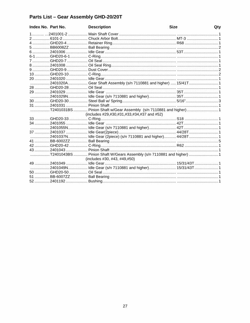
27
Parts List – Gear Assembly GHD-20/20T
Index No. Part No. Description Size Qty 1….…... …2401001-2 .................. Main Shaft Cover ..................................................... ...................................... 1 2 ................ 6101-2 ....................... Chuck Arbor Bolt...................................................... MT-3 ............................. 1 4 ................ GHD20-4 ................... Retainer Ring ........................................................... R68 ............................... 1 5 ................ BB6008ZZ ................. Ball Bearing ............................................................. ...................................... 2 6 ................ 2401006 .................... Idle Gear .................................................................. 53T ................................ 1 6-1 ............. GHD20-6-1 ................ C-Ring...................................................................... ...................................... 1 7 ................ GHD20-7 ................... Oil Seal .................................................................... ...................................... 1 8 ................ 2401008 .................... Oil Seal Ring ............................................................ ...................................... 1 9 ................ GHD20-9 ................... Dust Cover ............................................................... ...................................... 2 10 .............. GHD20-10 ................. C-Ring...................................................................... ...................................... 2 20 .............. 2401020 .................... Idle Gear .................................................................. ...................................... 1 .................. 2401020A .................. Gear Shaft Assembly (s/n 7110881 and higher) ..... 15/41T ........................... 1 28 .............. GHD20-28 ................. Oil Seal .................................................................... ...................................... 1 29 .............. 2401029 .................... Idle Gear ................................................................. 35T ................................ 1 .................. 2401029N .................. Idle Gear (s/n 7110881 and higher) ......................... 35T ................................ 1 30 .............. GHD20-30 ................. Steel Ball w/ Spring.................................................. 5/16” .............................. 3 31 .............. 2401031 .................... Pinion Shaft ............................................................. ...................................... 1 .................. T2401031BS ............. Pinion Shaft w/Gear Assembly (s/n 7110881 and higher) ............................. 1 (includes #29,#30,#31,#33,#34,#37 and #52) 33 .............. GHD20-33 ................. C-Ring...................................................................... S18 ............................... 1 34 .............. 2401055 .................... Idle Gear ................................................................. 42T ................................ 1 .................. 2401055N .................. Idle Gear (s/n 7110881 and higher) ......................... 42T ................................ 1 37 .............. 2401037 .................... Idle Gear(2piece) ..................................................... 44/28T ........................... 1 .................. 2401037N .................. Idle Gear (2piece) (s/n 7110881 and higher) ........... 44/28T ........................... 1 41 .............. BB-6002ZZ ................ Ball Bearing ............................................................. ...................................... 5 42 .............. GHD20-42 ................. C-Ring...................................................................... R62 ............................... 1 43 .............. 2401043 .................... Pinion Shaft ............................................................. ...................................... 1 .................. T2401043BS ............. Pinion Shaft W/Gears Assembly (s/n 7110881 and higher) ........................... 1 (includes #30, #43, #49,#50) 49 .............. 2401049 .................... Idle Gear .................................................................. 15/31/43T ...................... 1 .................. 2401049N .................. Idle Gear (s/n 7110881 and higher) ......................... 15/31/43T ...................... 1 50 .............. GHD20-50 ................. Oil Seal .................................................................... ...................................... 1 51 .............. BB-6007ZZ ................ Ball Bearing ............................................................. ...................................... 1 52 .............. 2401192 .................... Bushing .................................................................... ...................................... 1
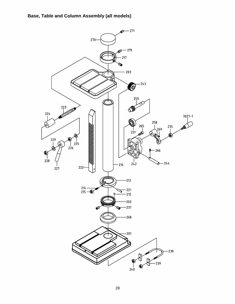
28
Base, Table and Column Assembly (all models)
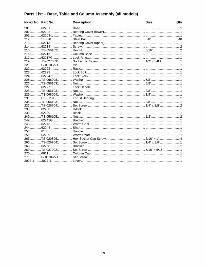
29
Parts List – Base, Table and Column Assembly (all models)
Index No. Part No. Description Size Qty 201 ............ 62201 ........................ Base......................................................................... ...................................... 1 202 ............ 62202 ........................ Bearing Cover (lower) .............................................. ...................................... 1 203 ............ 62203-1 ..................... Table ........................................................................ ...................................... 1 212 ............ SB-3/8 ....................... Steel Ball.................................................................. 3/8” .............................. 40 213 ............ 62213 ........................ Bearing Cover (upper) ............................................. ...................................... 1 214 ............ 62214 ........................ Screw ....................................................................... ...................................... 2 215 ............ TS-0561021 .............. Hex Nut .................................................................... 5/16” .............................. 2 216 ............ 62216 ........................ Column Base ........................................................... ...................................... 1 217 ............ 62217G ..................... Lock Ring ................................................................. ...................................... 1 219 ............ TS-0273031 .............. Socket Set Screw .................................................... 1/2” x 5/8”L .................... 1 221 ............ GHD20-221 ............... Pin............................................................................ ...................................... 1 222 ............ 62222 ........................ Rack......................................................................... ...................................... 1 223 ............ 62223 ........................ Lock Bolt .................................................................. ...................................... 1 224 ............ 62224-1 ..................... Lock Block ............................................................... ...................................... 1 225 ............ TS-0680081 .............. Washer .................................................................... 5/8” ................................ 1 226 ............ TS-0561031 .............. Nut ........................................................................... 5/8” ................................ 1 227 ............ 62227 ........................ Lock Handle ............................................................. ...................................... 1 228 ............ TS-0561031 .............. Nut ........................................................................... 3/8” ................................ 1 229 ............ TS-0680041 .............. Washer .................................................................... 3/8” ................................ 1 231 ............ BB-51103 .................. Thrust Bearing ......................................................... ...................................... 1 235 ............ TS-0561031 .............. Nut ........................................................................... 3/8” ................................ 1 237 ............ TS-0267041 .............. Set Screw ................................................................ 1/4” x 3/8” ...................... 2 238 ............ 62238 ........................ U-Bolt ....................................................................... ...................................... 1 239 ............ 62239 ........................ Block ........................................................................ ...................................... 1 240 ............ TS-0561051 .............. Nut ........................................................................... 1/2" ................................ 2 242 ............ 62242G ..................... Bracket..................................................................... ...................................... 1 243 ............ 62243 ........................ Worm Gear .............................................................. ...................................... 1 244 ............ 62244 ........................ Shaft ........................................................................ ...................................... 1 258 ............ 6158 .......................... Handle ..................................................................... ...................................... 1 259 ............ 62259 ........................ Worm Shaft .............................................................. ...................................... 1 265 ............ TS-0208061 .............. Hex Socket Cap Screw ............................................ 5/16” x 1” ....................... 4 266 ............ TS-0267041 .............. Set Screw ................................................................ 1/4" x 3/8” ...................... 1 268 ............ 62268 ........................ Bracket..................................................................... ...................................... 1 269 ............ TS-0270021 .............. Set Screw ................................................................ 5/16” x 5/16” .................. 1 270 ............ 6611 .......................... Column Cap ............................................................. ...................................... 1 271 ............ GHD20-271 ............... Set Screw ................................................................ ...................................... 1 3027-1 ....... 3027-1 ....................... Lever ........................................................................ ...................................... 1
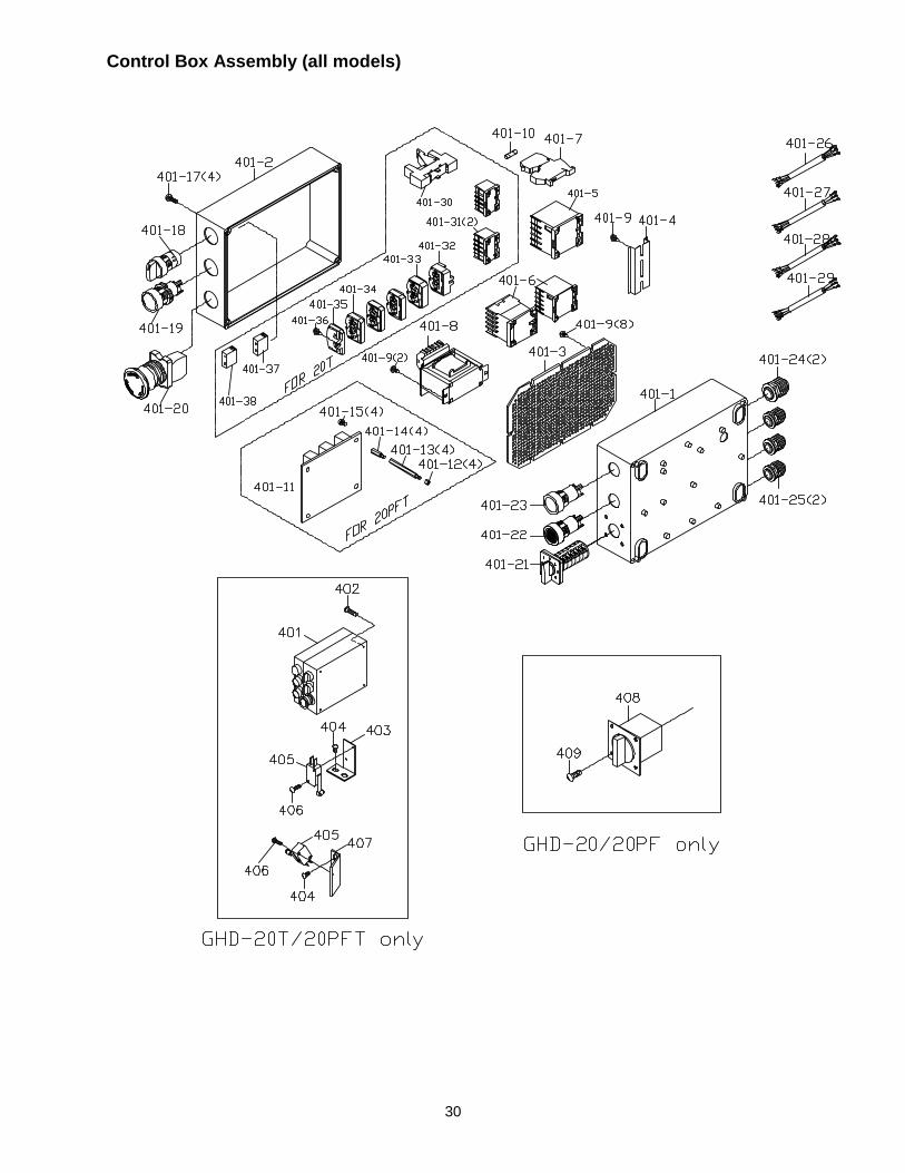
30
Control Box Assembly (all models)
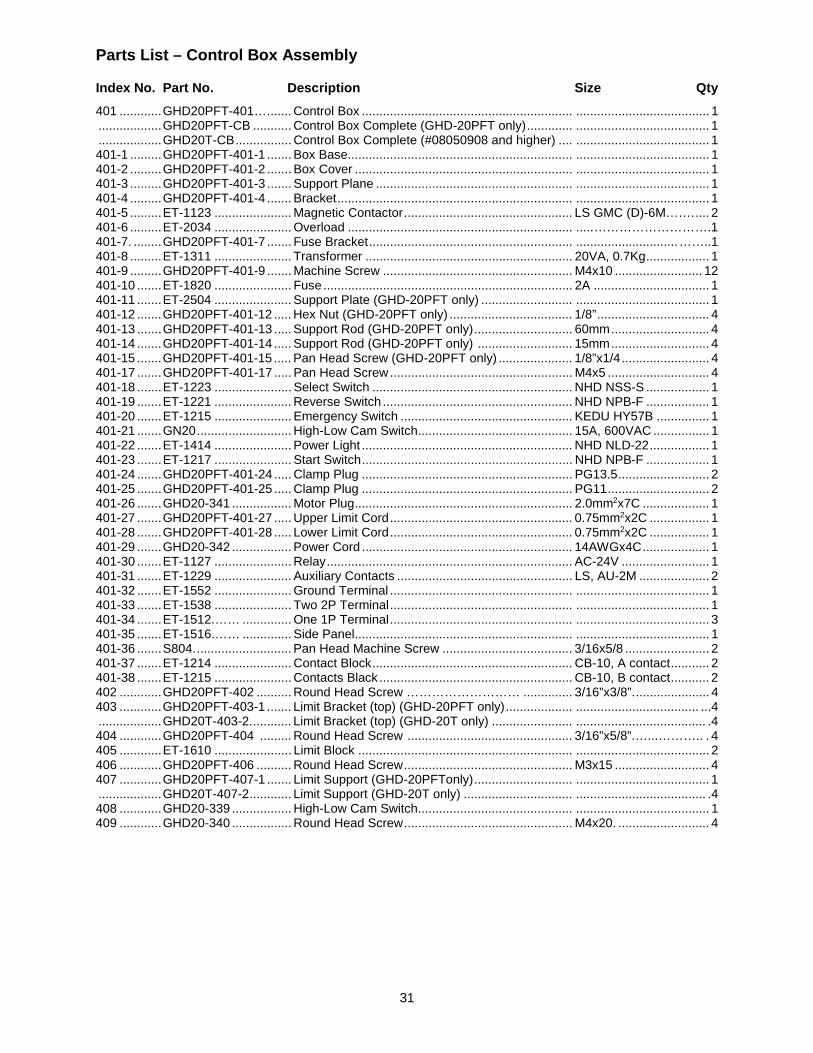
31
Parts List – Control Box Assembly
Index No. Part No. Description Size Qty 401 ............ GHD20PFT-401… ....... Control Box ............................................................ ...................................... 1 .................. GHD20PFT-CB ........... Control Box Complete (GHD-20PFT only) ............. ...................................... 1 .................. GHD20T-CB ................ Control Box Complete (#08050908 and higher) .... ...................................... 1 401-1 ......... GHD20PFT-401-1 ....... Box Base ................................................................ ...................................... 1 401-2 ......... GHD20PFT-401-2 ....... Box Cover .............................................................. ...................................... 1 401-3 ......... GHD20PFT-401-3 ....... Support Plane ........................................................ ...................................... 1 401-4 ......... GHD20PFT-401-4 ....... Bracket ................................................................... ...................................... 1 401-5 ......... ET-1123 ...................... Magnetic Contactor ................................................ LS GMC (D)-6M……. .... 2 401-6 ......... ET-2034 ...................... Overload ................................................................ ..... ……………………….1 401-7. ........ GHD20PFT-401-7 ....... Fuse Bracket .......................................................... ............................. ……..1 401-8 ......... ET-1311 ...................... Transformer ........................................................... 20VA, 0.7Kg .................. 1 401-9 ......... GHD20PFT-401-9 ....... Machine Screw ...................................................... M4x10 ......................... 12 401-10 ....... ET-1820 ...................... Fuse ....................................................................... 2A ................................. 1 401-11 ....... ET-2504 ...................... Support Plate (GHD-20PFT only) .......................... ...................................... 1 401-12 ....... GHD20PFT-401-12 ..... Hex Nut (GHD-20PFT only) ................................... 1/8” ................................ 4 401-13 ....... GHD20PFT-401-13 ..... Support Rod (GHD-20PFT only) ............................ 60mm ............................ 4 401-14 ....... GHD20PFT-401-14 ..... Support Rod (GHD-20PFT only) ........................... 15mm ............................ 4 401-15 ....... GHD20PFT-401-15 ..... Pan Head Screw (GHD-20PFT only) ..................... 1/8”x1/4 ......................... 4 401-17 ....... GHD20PFT-401-17 ..... Pan Head Screw .................................................... M4x5 ............................. 4 401-18 ....... ET-1223 ...................... Select Switch ......................................................... NHD NSS-S .................. 1 401-19 ....... ET-1221 ...................... Reverse Switch ...................................................... NHD NPB-F .................. 1 401-20 ....... ET-1215 ...................... Emergency Switch ................................................. KEDU HY57B ............... 1 401-21 ....... GN20 ........................... High-Low Cam Switch ............................................ 15A, 600VAC ................ 1 401-22 ....... ET-1414 ...................... Power Light ............................................................ NHD NLD-22 ................. 1 401-23 ....... ET-1217 ...................... Start Switch ............................................................ NHD NPB-F .................. 1 401-24 ....... GHD20PFT-401-24 ..... Clamp Plug ............................................................ PG13.5 .......................... 2 401-25 ....... GHD20PFT-401-25 ..... Clamp Plug ............................................................ PG11 ............................. 2 401-26 ....... GHD20-341 ................. Motor Plug .............................................................. 2.0mm2x7C ................... 1 401-27 ....... GHD20PFT-401-27 ..... Upper Limit Cord .................................................... 0.75mm2x2C ................. 1 401-28 ....... GHD20PFT-401-28 ..... Lower Limit Cord .................................................... 0.75mm2x2C ................. 1 401-29 ....... GHD20-342 ................. Power Cord ............................................................ 14AWGx4C ................... 1 401-30 ....... ET-1127 ...................... Relay ...................................................................... AC-24V ......................... 1 401-31 ....... ET-1229 ...................... Auxiliary Contacts .................................................. LS, AU-2M .................... 2 401-32 ....... ET-1552 ...................... Ground Terminal .................................................... ...................................... 1 401-33 ....... ET-1538 ...................... Two 2P Terminal .................................................... ...................................... 1 401-34 ....... ET-1512.…… .............. One 1P Terminal .................................................... ...................................... 3 401-35 ....... ET-1516.…… .............. Side Panel .............................................................. ...................................... 1 401-36 ....... S804. ........................... Pan Head Machine Screw ..................................... 3/16x5/8 ........................ 2 401-37 ....... ET-1214 ...................... Contact Block ......................................................... CB-10, A contact ........... 2 401-38 ....... ET-1215 ...................... Contacts Black ....................................................... CB-10, B contact ........... 2 402 ............ GHD20PFT-402 .......... Round Head Screw ……………………… .............. 3/16”x3/8”. ..................... 4 403 ............ GHD20PFT-403-1 ....... Limit Bracket (top) (GHD-20PFT only) ................... ................................... ...4 .................. GHD20T-403-2. ........... Limit Bracket (top) (GHD-20T only) ....................... ..................................... .4 404 ............ GHD20PFT-404 ......... Round Head Screw ............................................... 3/16”x5/8”.…...……….. . 4 405 ............ ET-1610 ...................... Limit Block ............................................................. ...................................... 2 406 ............ GHD20PFT-406 .......... Round Head Screw ................................................ M3x15 ........................... 4 407 ............ GHD20PFT-407-1 ....... Limit Support (GHD-20PFTonly) ............................ ...................................... 1 .................. GHD20T-407-2 ............ Limit Support (GHD-20T only) ............................... ..................................... .4 408 ............ GHD20-339 ................. High-Low Cam Switch ............................................ ...................................... 1 409 ............ GHD20-340 ................. Round Head Screw ................................................ M4x20. .......................... 4
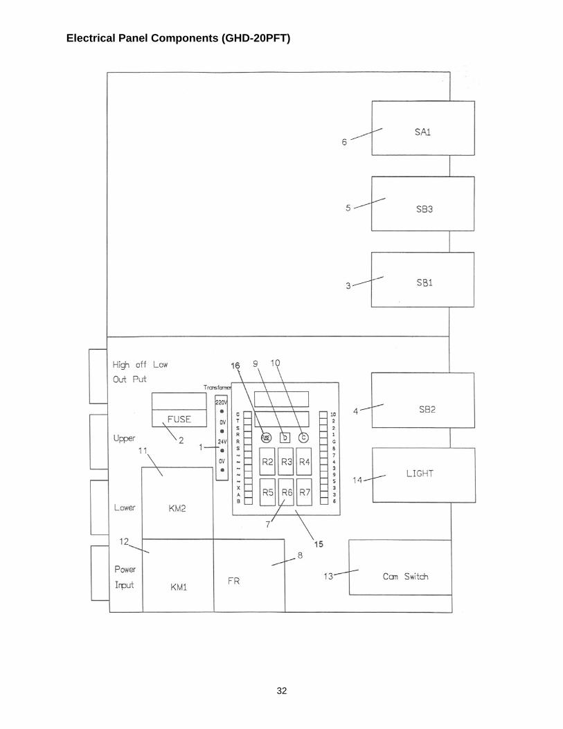
32
Electrical Panel Components (GHD-20PFT)
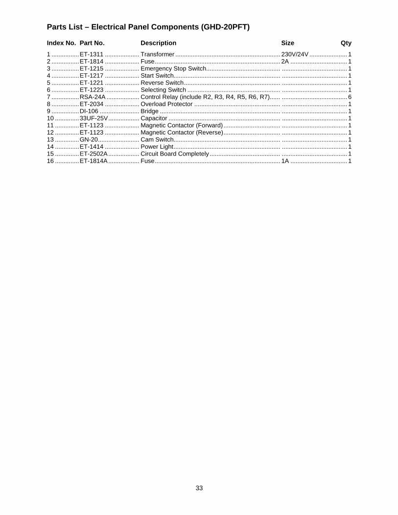
33
Parts List – Electrical Panel Components (GHD-20PFT)
Index No. Part No. Description Size Qty 1 ................ ET-1311 .................... Transformer ............................................................. 230V/24V ...................... 1 2 ................ ET-1814 .................... Fuse ......................................................................... 2A ................................. 1 3 ................ ET-1215 .................... Emergency Stop Switch........................................... ...................................... 1 4 ................ ET-1217 .................... Start Switch.............................................................. ...................................... 1 5 ................ ET-1221 .................... Reverse Switch ........................................................ ...................................... 1 6 ................ ET-1223 .................... Selecting Switch ...................................................... ...................................... 1 7 ................ RSA-24A ................... Control Relay (include R2, R3, R4, R5, R6, R7)...... ...................................... 6 8 ................ ET-2034 .................... Overload Protector .................................................. ...................................... 1 9 ................ DI-106 ....................... Bridge ...................................................................... ...................................... 1 10 .............. 33UF-25V .................. Capacitor ................................................................. ...................................... 1 11 .............. ET-1123 .................... Magnetic Contactor (Forward) ................................. ...................................... 1 12 .............. ET-1123 .................... Magnetic Contactor (Reverse) ................................. ...................................... 1 13 .............. GN-20 ........................ Cam Switch.............................................................. ...................................... 1 14 .............. ET-1414 .................... Power Light .............................................................. ...................................... 1 15 .............. ET-2502A .................. Circuit Board Completely ......................................... ...................................... 1 16 .............. ET-1814A .................. Fuse ......................................................................... 1A ................................. 1

34
Electrical Schematic (GHD-20/20PF only)
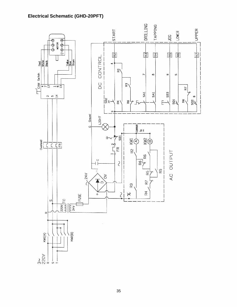
35
Electrical Schematic (GHD-20PFT)
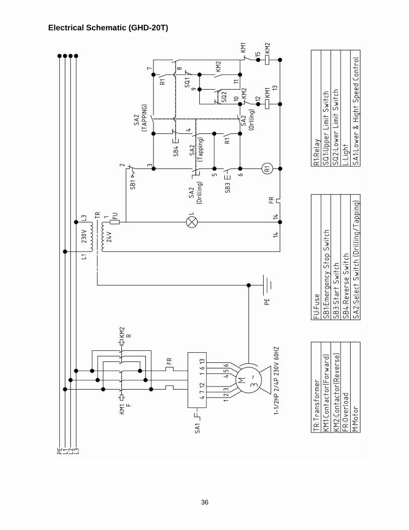
36
Electrical Schematic (GHD-20T)

37
This page intentionally left blank.

38
This page intentionally left blank.

39
This page intentionally left blank.

40
427 New Sanford Road LaVergne, Tennessee 37086
Phone: 800-274-6848 www.jettools.com