OPERATING INSTRUCTION - Graupner · OPERATING INSTRUCTION ... manual contains instructions for...
108
No. S1006 OPERATING INSTRUCTION Prior to use, please read this manual thoroughly. Keep this manual in a convenient place for quick and easy reference.
Transcript of OPERATING INSTRUCTION - Graupner · OPERATING INSTRUCTION ... manual contains instructions for...

No. S1006
OPERATING INSTRUCTION
Prior to use, please read this manual thoroughly. Keep this manual in a convenient place for quick and easy reference.

BASE MENU (Helicopter, Airplane, Gilder)
SYSTEM(Helicopter, Airplane, Gilder)
FUNCTION MENU (Helicopter)
3P3P3P3P3P3P3P4P4P4P5P5P
6P6P
6~10P10P11P
11~12P 12P
12~13P13~14P
14P15P
15~16P16~19P19~23P23~24P24~25P25~26P26~27P27~28P
28P28~29P
29P29~30P
30P30~32P33~36P36~38P38~40P40~41P
41P
42P42~44P44~45P45~50P50~51P51~52P
52P52~53P53~65P65~66P
66P66~72P72~74P
74P74~75P
75P76P76P76P
76~79P79~80P80~82P82~83P83~88P88~89P89~90P
90P90~91P91~92P93~94P94~95P95~97P97~99P
99~100P
100~101P101~102P
102P103P104P105P105P
106~107P
1. Q.Link(Quick Link) 1-1. NEW 1-2. NAM 1-3. CPY 1-4. DEL 1-5 NEXT2. D/R, EXP 3. Wing MIX4. THR.CRV 5. Idel Low6. Prog. MIX 7. Snap Roll 8. Aile Diff 9. Flap MIX 9-1. Flap 9-2. AILE >> FLAP 9-3. ELEV >> FLAP 9-4. FLAP >> ELEV10. Flap Sett (Airplane, Gilder)11. Airbrake (Airplane)12. Butterfly (Gilder)
1. ST mode2. Warning 3. Etc.set 4. Display5. Stick Cali 6. MP3• FIRMWARE UPDATE• SAFETY APPROVAL
1. Q.Link(Quick Link) 1-1 NEW 1-2 NAM 1-3 CPY 1-4 DEL2. D/R,EXP 3. PIT.CRV 4. THR.CRV 5. Gyr/Gover 6. THR.HOLD 7. SWASH
1. Model Select 1-1. SEL(Select model) 1-2. NEW(New Model) 1-3. Int.M(INT. Model) 1-4. EXT.M(EXT.Model) 1-5. RES(Model Reset) 1-6. CPY(Model Copy)2. Model Type 3. E.P.A 4. Reverse 5. Sub-Trim 6. THR.CUT 7. TX ctl8. Timer 9. Fail Safe 10. Trim Step11. SERVO 12. CH Set13. Out Swap
2
Contents • Before Use• Introduction• Support and Service• Openhobby A/S Center1. Box Contents2. Flying Safety 3. Features 4. Specification5. Stick tension adjustment 6.Transmitter Control Identification7. Binding8. Transmitter Programming Setup
FUNCTION MENU (Airplane, Gilder)
8. S.Limit 9. S.MIX10. THR.MIX11. PRO.MIX12. Trainer 13. PIT >> RUDD14. Telemetry 14-1. RX SELECT 14-2. SETTING & DATA VIWE 14-3. SENSOR SELECT 14-4. RF STATUS VIEW 14-5. VOICE TRIGGER 14-6. DISPLAY SETUP FOR TELEMETRY SENSOR

3
• BEFORE USE
• INTRODUCTION
• SUPPORT AND SERVICE
2. FLYING SAFETY
3. FEATURES
1. BOX CONTENTS
• Customer support
• mz-24 Transmitter • GR-24 receiver• Manual
• Transmitter charger• Warranty Card• 1x 4000mAh LiPo Battery
• USB PC interface set • SD Card adapter • SD Card case• USB Cable
• Micro SD Card • USB adapter wire • Transmitter strap• USB interface adapter wire
• A/S regulation
• Internet sales site
• Warranty regulation
Thank you for purchasing mz-24 HoTT 2.4GHz Radio System. This system is extremely versatile and may be used by beginners and pros alike. In order for you to make the best use of your system and to fly safely, please read this manual carefully. If you have any difficulties while using your system, please consult the manual, our online Frequently Asked Questions (on the web pages referenced below), your hobby dealer, or the SJ Service Center.Due to unforeseen changes in production procedures, the information contained in this manual is subject to change without notice.
This is a sophisticated hobby product and NOT a toy. It must be operated with caution and common sense and requires some basic mechanical ability. Failure to operate this product in a safe and responsible manner could result in injury or damage to the product or other property. This product is not intended for use by children without direct adult supervision. Do not attempt disassembly, use with incompatible components or augment product in any way without the approval of Graupner/SJ. This manual contains instructions for safety, operation and maintenance. It is essential to read and follow all the instructions and warnings in the manual, prior to assembly, setup or use, in order to operate correctly and avoid damage or serious injury.
1. Do not fly your model near spectators, parking areas or any other area that could result in injury to people or damage of property.
2. The radio system is affected by signal environment and the electronic jamming signals can cause disorientation and loss of control of your aircraft.
3. Since models are hazardous when operated and maintained incorrectly, install and operate a radio control system correctly and always pilot a model so the model is kept under control in all conditions
4. Ensure that all channels are working in the proper manner. 5. Do not fly during adverse weather conditions. Poor visibility can cause disorientation and loss of
control of your aircraft. Strong winds can cause similar problems6. When working with a model, always power on the transmitter first and power off the transmitter last.7. After a model is bound to a transmitter and the model is set up in the transmitter, always bind the
model to the transmitter again to establish failsafe settings.8. When working with a model, always power on the transmitter first and power off the transmitter last. 9. Ensure all batteries are full charged before flying.10. Only to use the recommended adapter when charging the battery of the transmitter and receiver11.The transmitter shouldn’t be switched off at any time during flight12. Perform a range check of the transmitter and the model before flying the model13. Make sure all control surfaces correctly respond to transmitter controls before flying.14. Perform the programming setup of the transmitter after removing a power battery from a model or
stopping an engine of a model.15. Don’t move or touch the transmitter antenna during flight
1. HoTT (Hopping Telemetry Transmission) The use of up to 75 hopping channels provides advanced reliable operation while keeping from
any external interference. 2. This HoTT radio system gives user real-time information on various useful data such as user model’s RPM, voltage, temperature, user programmable warning, and so on.3. All telemetry data are directly obtained from telemetric speed controllers equipped with this HoTT system without having to install separate sensor devices.4. Future-proof update capability using data interface of USB or Data pin.5. Advanced HoTT wireless trainer system makes Teacher and Pupil system more enjoyable and gives user convenience for the teaching/learning.6. Simple, ultra-fast binding of transmitter and receiver.
Graupner/SJ mz-24 HoTT radio system is used to airplane, helicopter and glider and should be a perfect choice for anyone who needs a high quality radio. This HoTT radio system gives user real-time information on various useful data such as user model’s RPM, voltage, temperature, user programmable warning, and so on which are directly obtained from telemetric speed controllers equipped with this HoTT system without having to install separate sensor devices. Of course, all of those telemetric data can be also transmitted from separate sensor devices.
WARNING : Read the ENTIRE instruction manual to become familiar with the features of the product before operating. Failure to operate the product correctly can result in damage to the product, personal property and cause serious injury.
Please feel free to ask any question by e-mail or phone. We’ve been trying to deal with your ques-tion. We are open from nine to six, Monday to Friday in Korea. We may respond to your question by e-mail as soon as possible when we are close.
Only when the product is faulty after normal operation within the warranty period, we will repair the product for free based on our regulations. The repair is paid for by the consumer when the damage is due to use in improper ways or beyond the warranty period..
Please feel free to contact “www.openhobbby.com” to get all information on product features, specifications, running events and the newest product line up..
Refer the WARRANTY Card in a Package
• OPENHOBBY A/S CENTER
8F, 202 Dong, Chunui Techno-Park II, 18, 198 street, Bucheon-ro, Wonmi-Gu, Bucheon-Shi, Gyungki-Do KOREA 420-857 Phone: 82-32-623-0706 FAX: 82-32-623-0720Customer Service E-mail: [email protected]

4
Frequency band Modulation
Output power Current drain
Operating voltage
2.4~2.4835GHzFHSS
100mWapprox 125mA
3.4V~6V
Transmitter mz-24 Receiver GR-24
2.4~2.4835GHzFHSS
-approx 70mA
3.6V~8.4V
4. SPECIFICATION
You may release the stick tension with ST1 or ST3 tension release bolts. Turn the bolts clockwise then the stick tension is released
- Mode 1: ST1 tension release bolt is used- Mode 2: ST3 tension release bolt is used
The other can be adjusted for your purpose
ST3 tensionadjustment blot
ST2 tensionadjustment blot
ST1 tension adjustment blot for helicopter type
ST1 tension adjustment blot for airplane type
ST3 tension adjustment blot for airplane type
ST3 tension adjustment blot for helicopter type
6. TRANSMITTER CONTROL IDENTIFICATION
5. STICK TENSION ADJUSTMENT
ST1, ST3 tension release blot
ST1 tensionadjustment blot
ST4 tensionadjustment blot
NECKSTRAP LUG
DV4
DT2DV2
DT1
DV1
S5 SWITCH
S2 SWITCH
S1 SWITCH
POWER SWITCH
POWER SWITCH
ELEV/RUDD STICK
ELEV TRIM
RUDD TRIM AILE TRIM
S3 SWITCH
S4 SWITCH
THRO TRIM
ANTENNA
DV3
ENT BUTTONESC BUTTON
THRO/AILE STICK
DIRECTION BUTTONDIRECTION
BUTTON
R S
TELEMETRY
EARPHONE
SD CARD
USB
DSC
L S
Charge Socket
TX Handel
5
Touch
Touch
Touch
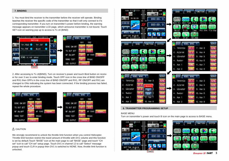
7. BINDING
8. TRANSMITTER PROGRAMMING SETUP
1. You must bind the receiver to the transmitter before the receiver will operate. Binding teaches the receiver the specific code of the transmitter so that it will only connect to it’s corresponding transmitter. If you turn on transmitter’s power before binding, the warning message appears on transmitter LCD page, which announce transmitter is not bound. Touch SET icon on warning pop up to access to Tx ctl (BIND)
2. After accessing to Tx ctl(BIND), Turn on receiver’s power and touch Bind button on receiv-er for over 3 sec to enter binding mode. Touch OFF icon in the cross line of BIND ON/OFF and RX1 then OFFs in the cross line of BIND ON/OFF and RX1, RF ON/OFF and RX1 are changed to ONs indicating the system has been connected. If the binding process has failed, repeat the whole procedure.
BASE MENUTurn on transmitter’s power and touch B icon on the main page to access to BASE menu.
CAUTION
We strongly recommend to unlock the throttle limit function when you control Helicopter. Throttle limit function restrict the travel amount of throttle with DV1 volume and this function is set by default.Touch “BASE” icon at the main page to call “BASE” page and touch “CH set” icon to call “CH set” setup page. Touch DV1 in channel 12 to call “Select” message popup and touch CLR in popup then DV1 is switched to NONE. Now, throttle limit function is unlocked.
Touch
Touch
Touch
YES YES
MODELCHANGE
MODELCHANGE
NO NO
Touch
6
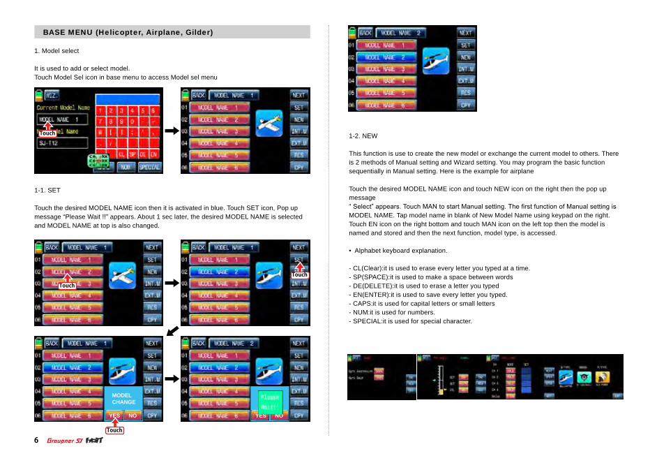
1. Model select
It is used to add or select model. Touch Model Sel icon in base menu to access Model sel menu
1-1. SET
Touch the desired MODEL NAME icon then it is activated in blue. Touch SET icon, Pop up message “Please Wait !!” appears. About 1 sec later, the desired MODEL NAME is selected and MODEL NAME at top is also changed.
1-2. NEW
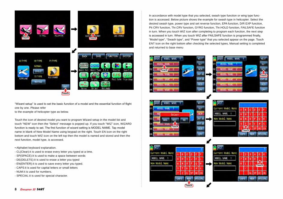
This function is use to create the new model or exchange the current model to others. There is 2 methods of Manual setting and Wizard setting. You may program the basic function sequentially in Manual setting. Here is the example for airplane
Touch the desired MODEL NAME icon and touch NEW icon on the right then the pop up message “ Select” appears. Touch MAN to start Manual setting. The first function of Manual setting is MODEL NAME. Tap model name in blank of New Model Name using keypad on the right. Touch EN icon on the right bottom and touch MAN icon on the left top then the model is named and stored and then the next function, model type, is accessed.
• Alphabet keyboard explanation.
- CL(Clear):it is used to erase every letter you typed at a time.- SP(SPACE):it is used to make a space between words- DE(DELETE):it is used to erase a letter you typed- EN(ENTER):it is used to save every letter you typed. - CAPS:it is used for capital letters or small letters- NUM:it is used for numbers.- SPECIAL:it is used for special character.
BASE MENU (Helicopter, Airplane, Gilder)

Touch
Touch
Touch
Touch
Touch
Touch
Touch
Touch
Touch
Touch
Touch
Touch
Touch
Touch
7
In accordance with model type that you selected, swash type function or wing type function is accessed. Below picture shows the example for wing type in airplane. Select the desired wing type, tail type and power type in turn. If all procedures have been done correctly, all types that you selected appear on the page. Touch ENT icon on the right bottom after check-ing the selected types, Manual setting is completed and returned to base menu
Touch Touch
Touch
Touch
Touch
Touch
Touch
Touch
Touch
8
“Wizard setup” is used to set the basic function of a model and the essential function of flight one by one. Please refer to the example of helicopter type as below.
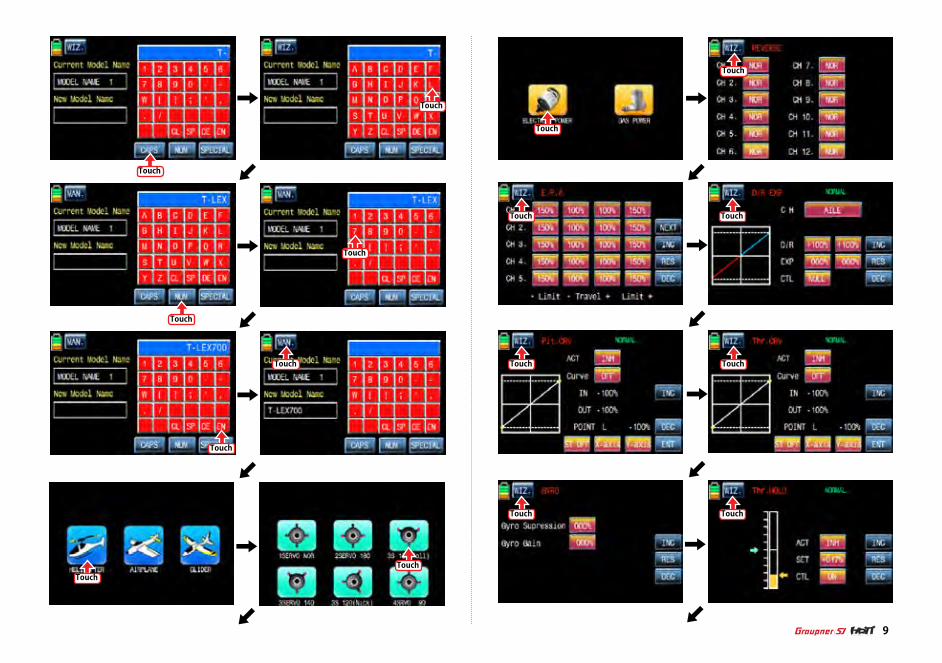
Touch the icon of desired model you want to program Wizard setup in the model list and touch “NEW” icon then the “Select” message is popped up. If you touch “WIZ” icon, WIZARD function is ready to set. The first function of wizard setting is MODEL NAME. Tap model name in blank of New Model Name using keypad on the right. Touch EN icon on the right bottom and touch WIZ icon on the left top then the model is named and stored and then the next function, model type, is accessed.
• Alphabet keyboard explanation.- CL(Clear):it is used to erase every letter you typed at a time.- SP(SPACE):it is used to make a space between words- DE(DELETE):it is used to erase a letter you typed- EN(ENTER):it is used to save every letter you typed. - CAPS:it is used for capital letters or small letters- NUM:it is used for numbers.- SPECIAL:it is used for special character.
In accordance with model type that you selected, swash type function or wing type func-tion is accessed. Below picture shows the example for swash type in helicopter. Select the desired swash type, power type and set reverse function, EPA function, D/R EXP function, Pit CRV function, Thr.CRV function, GYRO function, Thr.HOLD function, FAILSAFE function in turn. When you touch WIZ icon after completing to program each function, the next step is accessed in turn. When you touch WIZ after FAILSAFE function is programmed finally, “Model type”, “Swash type”, and “Power type” that you selected appear on the page. Touch ENT icon on the right bottom after checking the selected types, Manual setting is completed and returned to base menu
Touch
Touch
Touch
Touch
Touch
Touch
Touch
Touch
Touch
Touch
Touch
Touch Touch
Touch
9
Touch Touch

Touch
Touch
Check Check
Touch
Touch
Touch
Touch
Touch
Touch
10
1-3. INT.M (Internal Model)
It is used to copy the model memory in SD Card into the model list of transmitter. To make use of INT.M function, you need SD Card that has the programmed model file. If you put SD Card into SD Card slot on the back of transmitter, “SD Card” icon is lighted in the transmit-ter main page. When the icon is lighted, touch the base setup icon to call the base setup page. In the page, touch “Model Select” icon to call the “Model Sel” setup page and touch the copy destination then it is activated in blue. Touch “INT.M” icon then the model list in SD Card appears and then select the source model to copy. The popup message indicating the destination and source appears. Touch YES, if they are correct, then “Please wait” message is displayed and a few seconds later, the model data in SD Card is copied to the model list in transmitter.

Check Check
Touch
Touch
Touch
Touch
Touch
Touch
Touch
11
1-4. EXT.M (External Model)
This function is used to copy the model in transmitter into SD Card. In order to use EXT.M function, you need to plug SD Card into SD Card slot on the back of transmitter. When it is plugged into the slot, “SD Card” icon is lightened in the transmitter main page. Touch Base setup icon to call the base setup page. In the page, touch “Model Select” icon to call the “Model Select” setup page and touch the source model to copy in transmitter then it is acti-vated in blue. Touch “EXT.M” icon then the popup message “SD Card EXPORT?” appears. Touch YES then “Please wait” message is displayed and a few seconds later, the model data in transmitter is copied to SD Card now
1-5. RES(RESET)
It allows you to remove the selected models in model list. Refer to the example of Model 01 as shown below. At first, you need to select the desired model that you want to remove then the model icon is activated in blue. “Please wait” message is popped up when you touch “YES” icon. All the data of the corresponding model is removed within a few second.
YES
INITIALIZESURE
NO YES
MODELCHANGE
NO
Touch

Touch
Touch
Touch
Touch
Touch
Touch
Touch
Touch
12
1-6. CPY(Model Copy)
The Copy function is used to copy the programmed values of a model into the other model. Touch the source model to copy, it is activated in blue. Now touch “CPY” icon on the right bottom and touch the copy destination then it is activated in blue as well. The popup message indicating the destination and source appear. Touch YES, if they are correct, then “Please wait” message is displayed and a few seconds later, the source data is copied to the copy destination.transmitter.
2. Model type
It is used to reset the model type. Please note that all the value, excepting for model name, is reset when “Model type” is reset. Touch “Model type” icon on base menu page to call the model type setup page, the preset “model type”, “swash type” and “power type” is displayed. The below example tells you how to change from the heli type to air type. If you touch M/TYPE icon, you may select airplane form preset Helicopter at M/TYPE page again. In accordance with the selected model type, ”Swash type” or “Wing type” appear. Since the air-plane type is selected, the wing type is shown in the example below. Select the desired wing type, tail type and power type in turn. If all procedures have been done correctly, all types that you selected appear on the page. Touch ENT icon on the right bottom after checking the selected types, Manual setting is completed and returned to base menu

Touch
Touch
Touch
Touch
Touch
Touch
Touch
Touch
Touch
Touch
Touch
13
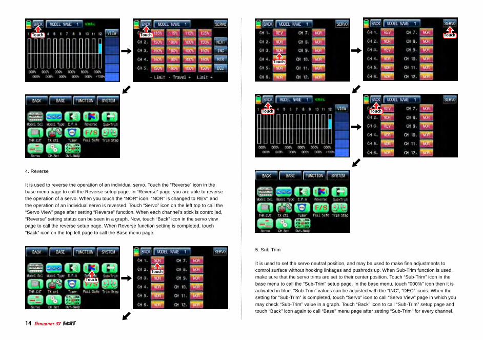
3. E.P.A
E.P.A is used to adjust Servo operation angle and limitation for each channel. Touch “E.P.A” icon on the base menu page to call E.P.A setup page. “Limit” and “travel” can be set individ-ually. When you touch each icon, it is activated in blue and you may adjust the values with “INC” and “DEC” buttons. Touch NEXT icon on the right to go and set more channels’ E.P.A. after setting each channel’s E.P.A, touch “SERVO” icon to call “SERVO VIEW” page. By moving each channel’s stick, you may check E.P.A value in the graph. When “BACK” icon in the “SERVO VIEW” page is touched, you may return to the base menu page.
Touch
Touch
Touch Touch
Touch
Touch
Touch Touch
Touch
Touch
14
5. Sub-Trim
It is used to set the servo neutral position, and may be used to make fine adjustments to control surface without hooking linkages and pushrods up. When Sub-Trim function is used, make sure that the servo trims are set to their center position. Touch “Sub-Trim” icon in the base menu to call the “Sub-Trim” setup page. In the base menu, touch “000%” icon then it is activated in blue. “Sub-Trim” values can be adjusted with the “INC”, “DEC” icons. When the setting for “Sub-Trim” is completed, touch “Servo” icon to call “Servo View” page in which you may check “Sub-Trim” value in a graph. Touch “Back” icon to call “Sub-Trim” setup page and touch “Back” icon again to call “Base” menu page after setting “Sub-Trim” for every channel.
4. Reverse
It is used to reverse the operation of an individual servo. Touch the “Reverse” icon in the base menu page to call the Reverse setup page. In “Reverse” page, you are able to reverse the operation of a servo. When you touch the “NOR” icon, “NOR” is changed to REV” and the operation of an individual servo is reversed. Touch “Servo” icon on the left top to call the “Servo View” page after setting “Reverse” function. When each channel’s stick is controlled, “Reverse” setting status can be seen in a graph. Now, touch “Back” icon in the servo view page to call the reverse setup page. When Reverse function setting is completed, touch “Back” icon on the top left page to call the Base menu page.

Touch
Touch
Touch
Touch
Touch
Touch
Touch
Touch
Touch Touch
15
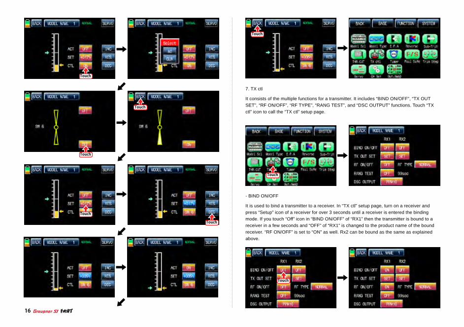
6. THR.CUT
This function is used to stop the operation of engine. THR.CUT function works from below one-third position of the full movement range of throttle stick. Touch “THR.CUT” icon in the base menu page to call the “THR.CUT” setup page. When touching “INH” icon in “ACT” line, you may change the value to “OFF”. When touching “On” icon in “CTL”, the message “Select” is popped up. Now, move the switch with your choice then this switch is set to on/ off switch for “THR.CUT” and the switch setup page appears. You may change ON/OFF by touching icons. When the switch is moved to the direction of ON, the function is operated. After the switch setup is completed, touch “BACK” icon on the left top to return “THR.CUT” setup page then set the value in “SET” line. Touch “017%” icon to activate it in blue and touch “INC” and “DEC” icons to decide the throttle position when “THR.CUT” is on. Now the servo of throttle channel is operated to the corresponding position. Touch “Back” icon to return the base menu page.
Touch
Touch
Touch
Touch
Touch
Touch
Touch
Touch
Touch
Touch
16
7. TX ctl
It consists of the multiple functions for a transmitter. It includes “BIND ON/OFF”, “TX OUT SET”, “RF ON/OFF”, “RF TYPE”, “RANG TEST”, and “DSC OUTPUT” functions. Touch “TX ctl” icon to call the “TX ctl” setup page.
- BIND ON/OFF
It is used to bind a transmitter to a receiver. In “TX ctl” setup page, turn on a receiver and press “Setup” icon of a receiver for over 3 seconds until a receiver is entered the binding mode. If you touch “Off” icon in “BIND ON/OFF” of “RX1” then the transmitter is bound to areceiver in a few seconds and “OFF” of “RX1” is changed to the product name of the bound receiver. “RF ON/OFF” is set to “ON” as well. Rx2 can be bound as the same as explained above.

Touch
Touch
Touch Touch
Touch
Touch
Touch
Touch
17
- TX OUT SET
It is used to edit the receiver’s “out-channel” connected to each channel of transmitter as you want. For example, when “2 Elevator” function is used, the “CH3” and “CH8” out pins of receiver are used in the traditional channel setup, however, if the receiver’s CH4 pin is set for the transmitter’s CH3 using “TX OUT SET” function, the CH4 and CH3 pin are operated for the “2 ELEVATOR” function. To make use of this function, a receiver should be bound first. When you bind the receiver to RX1 and RX2 and then touch “Set” icon in “TX OUT SET” to call “TX OUT SET” setup page. “TX OUT SET” page is differently shown according to the number of receiver’s channel which is bound to a transmitter. Basically, the order of transmit-ter’s channel is set as the same as the order of receiver’s out-pin. Touch the desired channel number to activate in blue and change it to the channel that you want to match with “INC” and “DEC” button and then touch “STO” icon to transmit the setup data to the receiver. The other channels are set as the same as explained above.NOTE: Since “TX OUT SET” function is set the receiver by transmitter, you should touch the “STO” icon to transmit the setup data to the receiver and to save the data on a receiver for operation.
- RF ON/OFF
It is used to turn on or off transmitter’s “RF” function. If you are not flying a model but pro-gramming transmitter only, you are able to save the battery of the transmitter by setting RF to turn off. Under “OFF” status, transmitter is disconnected with the receiver. Touch “ON” icon in “RF ON/OFF” to change to “OFF”
- RF TYPE
mz-12 offers 2 RF types, NORMAL and FRANCE, to comply with country regulation. “NORMAL” type is usually used in most countries, but you need France RF setting to comply with France regulations in FANCE. France RF setting should only be turned on when operat-ing your transmitter in France outdoors. “NORMAL” type can be changed into “FRANCE” type by touching “NORMAL” icon. If the “FRANCE” icon is touched again, it can be changed into “NORMAL” icon.
Touch
Touch
Touch
Touch
Touch
Touch
Touch
Touch
18
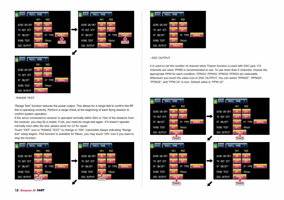
- RANGE TEST
“Range Test” function reduces the power output. This allows for a range test to confirm the RF link is operating correctly. Perform a range check at the beginning of each flying session to confirm system operation.If the servo connected to receiver is operated normally within 50m or 70m of the distance from the receiver, you may fly a model, if not, you need do range test again. If it doesn’t operate normally even after the test, please send mz-12 for repair.Touch “OFF” icon in “RANGE TEST” to change to “ON”, transmitter beeps indicating “Range test” setup begins. This function is available for 99sec. you may touch “ON” icon if you want to stop the function.
- DSC OUTPUT
It is used to set the number of channel when Trainer function is used with DSC jack. If 5 channels are used, PPM5 is recommended to use. To use more than 5 channels, choose the appropriate PPM for each condition. PPM10, PPM16, PPM18, PPM24 are selectable. Whenever you touch the value icon in DSC OUTPUT, You can select “PPM10”, “PPM16”, “PPM18”, and “PPM 24” in turn. Default value is “PPM 10”.

Touch Touch
Touch
Touch Touch
19
8. TIMER
Timer function may be set for any desired time ,i.e. model time, date, time, etc. Two independ-ent timers, TIMER1 and TIMER2, are provided for each model. Touch “Timer” icon in base menu page to call the timer setup page.
To set the model time, touch “MODE” icon and then select “UP” or “DOWN”. The default value is UP. Timer may be set count-down or count-up operation with your choice. Count-up timer continues counting from zero to the setup time and Count-down timer keeps counting from the setup time to zero.
After “MODE” setup, you need to set “ALARM”. The alarm sounds from the last 20 seconds in the setup time. It has the 2 seconds intervals for the first 10 seconds and has the 1 second interval for the next 10 seconds.
In the “Timer” setup page, set “TIMER 1” first. The timer in the first line is used when to save the flight data on SD card. Bind transmitter and receiver and Insert SD card into SD card slot in the rear of transmitter. Touch the value in minute or second to operate or stop timer. The flight data starts to be saved on SD card when timer starts to operate and stop to save when timer stop to operate. Touch “T.RES” icon to reset timer. Since the timer in TIMER 1 is operat-ed with ALARM timer at a time, you need to operated ALARM timer to use it
Touch

Touch
Touch
Touch
Touch
Touch
Touch
20
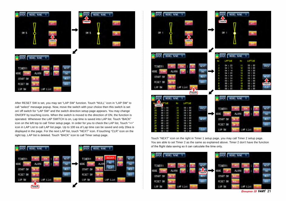
After “ALARM” setup, you may set “START SW”. Touch “NULL” icon in “START SW” to call “Select” message popup. Now, move the switch with your choice then this switch is set on/ off switch for “START SW” and the switch direction setup page appears. You may change ON/OFF by touching icons. When the switch is moved to the direction of on, the function is operated. Touch “Back” icon to return TIMER setup page
When START SW setup is completed, you may set RESET SW function. Touch the “NULL” icon in “RESET SW” to call “select” message popup. Now, move the switch with your choice then this switch is set to on/ off switch for “RESET SW” and the switch direction setup page appears. You may change ON/OFF by touching icons. When the switch is moved to the direc-tion of ON, the function is operated. Touch “Back” icon to return TIMER setup page
Touch
Touch
Touch
Touch
Touch
Touch
Touch
TouchTouch
21
After RESET SW is set, you may set “LAP SW” function. Touch “NULL” icon in “LAP SW” to call “select” message popup. Now, move the switch with your choice then this switch is set on/ off switch for “LAP SW” and the switch direction setup page appears. You may change ON/OFF by touching icons. When the switch is moved to the direction of ON, the function is operated. Whenever the LAP SWITCH is on, Lap time is saved into LAP list. Touch “BACK” icon on the left top to call Timer setup page. In order for you to check the LAP list, Touch “>>” icon in LAP List to call LAP list page. Up to 100 ea of Lap time can be saved and only 20ea is displayed in the page. For the next LAP list, touch “NEXT” icon. If touching “CLR” icon on the right top, LAP list is deleted. Touch “BACK” icon to call Timer setup page.
Touch “NEXT” icon on the right in Timer 1 setup page, you may call Timer 2 setup page.You are able to set Timer 2 as the same as explained above. Timer 2 don’t have the function of the flight data saving so it can calculate the time only.

Touch
Touch
Touch
Touch
Touch
Touch
Touch
Touch
Touch
Touch
Touch
Touch
Touch
Touch
Touch
Touch
22
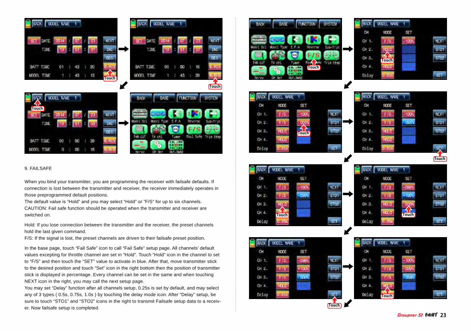
After Timer 2 setup, touch “NEXT” icon on the right. You may call the page of the date/ time setup. Touch “SET” icon to activate it in blue and touch the desired value to activate in blue. With “INC” and “DEC” buttons, you may adjust the values for the date and time as the picture shown below. BATT TIME and MODEL TIME can be reset by touching the corresponding B.RES and M.RES icons.
Touch
Touch
Touch
Touch
Touch
Touch
Touch
TouchTouch
Touch
Touch
23
9. FAILSAFE
When you bind your transmitter, you are programming the receiver with failsafe defaults. If connection is lost between the transmitter and receiver, the receiver immediately operates in those preprogrammed default positions. The default value is “Hold” and you may select “Hold” or ”F/S” for up to six channels. CAUTION: Fail safe function should be operated when the transmitter and receiver are switched on.
Hold: If you lose connection between the transmitter and the receiver, the preset channels hold the last given command.F/S: If the signal is lost, the preset channels are driven to their failsafe preset position.
In the base page, touch “Fail Safe” icon to call “Fail Safe” setup page. All channels’ default values excepting for throttle channel are set in “Hold”. Touch “Hold” icon in the channel to set to “F/S” and then touch the “SET” value to activate in blue. After that, move transmitter stick to the desired position and touch “Set” icon in the right bottom then the position of transmitter stick is displayed in percentage. Every channel can be set in the same and when touching NEXT icon in the right, you may call the next setup page. You may set “Delay” function after all channels setup, 0.25s is set by default, and may select any of 3 types ( 0.5s, 0.75s, 1.0s ) by touching the delay mode icon. After “Delay” setup, be sure to touch “STO1” and “STO2” icons in the right to transmit Failsafe setup data to a receiv-er. Now failsafe setup is completed.

Touch
Touch
TouchTouch
Touch Touch
Touch
Touch
24
Touch
Touch
Touch
Touch
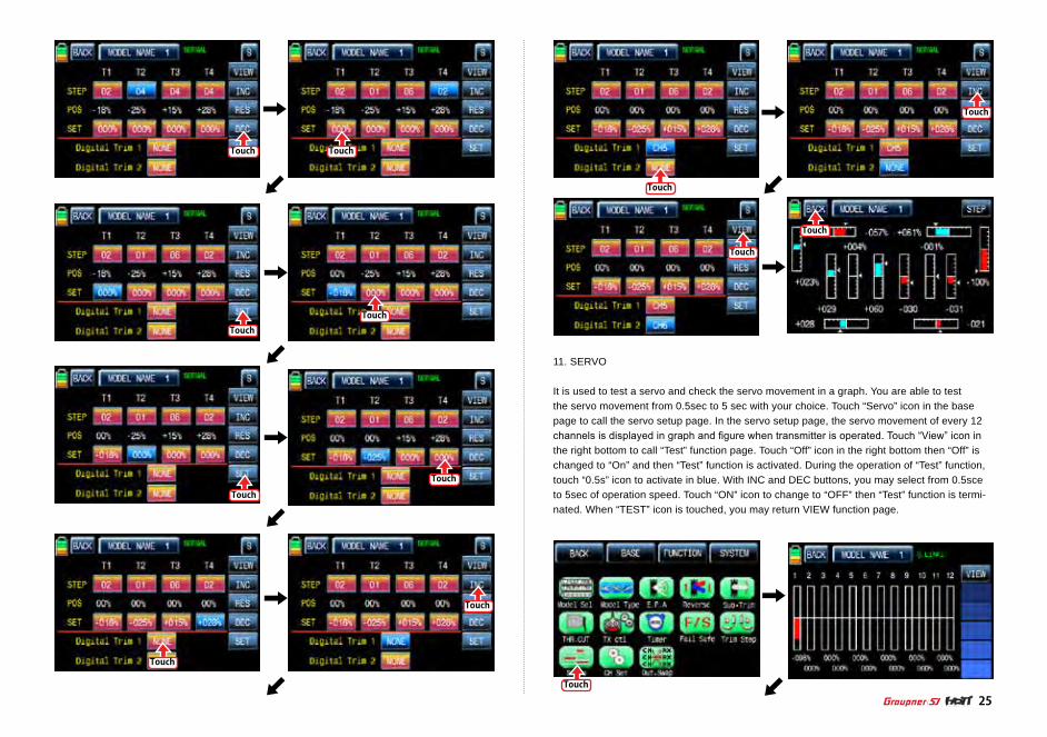
10. TRIM STEP
It allows you to check all function values of “Digital trim step”, “DT1”, “DT2”, ‘Digital volume”, and “Side slide”. Touch “Trim Step” icon in base menu page to call Trim Step setup page. The step value indicates the amount that the trim is moved in the range, 100, when operating trim key one time. “4” is set by default and it means that the trim is moved as much as “4” by operating trim key one time. Touch and activate the values in STEP line and adjust the values with INC” and “DEC” but-tons. The programmed trim values are displayed in “POS” line and can be saved on transmit-ter. If you save the programmed trim, the value is reset to the natural, 00%, and it can be ver-ified in “POS” line as well. Touch and activate the values, 000%, in SET line and touch “SET” icon in the right bottom then the value in POS line is switched to 000%, the programmed trim value is saved in SET line. After Trim STEP and SET setup, you may adjust the function value of “Digital trim 1” and ‘Digital trim 2”. Their default value is set as “None”. Touch any of options for ‘DT1” and “DT2” to activate in blue. You may adjust the function value with “INC” and “DEC” buttons. Touch “View” icon in the right to call the next page that you can see all setup data such as Trim posi-tion, DT1, DT2, Digital volume and Side slide. Touch “BACK” icon to return the previous page.
Touch Touch
Touch
Touch
Touch
Touch
Touch
Touch
Touch
Touch
Touch
Touch
Touch
25
11. SERVO
It is used to test a servo and check the servo movement in a graph. You are able to test the servo movement from 0.5sec to 5 sec with your choice. Touch “Servo” icon in the base page to call the servo setup page. In the servo setup page, the servo movement of every 12 channels is displayed in graph and figure when transmitter is operated. Touch “View” icon in the right bottom to call “Test” function page. Touch “Off” icon in the right bottom then “Off” is changed to “On” and then “Test” function is activated. During the operation of “Test” function, touch “0.5s” icon to activate in blue. With INC and DEC buttons, you may select from 0.5sce to 5sec of operation speed. Touch “ON” icon to change to “OFF” then “Test” function is termi-nated. When “TEST” icon is touched, you may return VIEW function page.

Touch
Touch
Touch
Touch
Touch
Touch
Touch
TouchTouch
Touch
26
12. CH Set
It is used to set the channel of a transmitter. The basic setup of the transmitter’s channel is set differently depending on 3 different types (“model type”, “wing type”, and “swash type”) and mz-12 offers AUX channel to set the switch, volume, and side lever for your purpose. Touch “CH set” icon on base menu page to call to “CH set” setup page. In “Ch Set” setup page, the basic functions of the transmitter which is connected individually to every channel are displayed. AUX channels are displayed as NONE when they are not connected to a servo. To connect AUX channel to a servo, touch “NONE” icon to call the “select” message popup and move the switch, volume or side lever with your choice then the selected switch, volume or side lever is set to AUX channel and the connected servo is controlled. Touch “SERVO” icon on the right to call the “SERVO VIEW” page, you may check the operating status of servo connected AUX channel in this page. Touch “BACK” icon to return the previous page.

Touch
Touch
Touch
Touch
Touch
Touch
Touch
Touch
Touch
Touch
27
13. Out Swap
This function is used to edit the channel connection between transmitter and receiver. (It is similar to TX OUT SET function in TX ctl, but Out Swap function is operated without trans-mitting the setup data to a receiver unlike TX OUT SER function. Even if receiver channels are more than transmitter channels, you are able to set receiver channel in “TX OUT SET” function, but “Out Swap” function allows you to edit only twelve channels connected to the transmitter.)
In base menu page, touch “Out.Swap” icon to call “Out. Swap” setup page. The channel order of transmitter is set as the same as the order of receiver. Touch the channel number to acti-vate in blue and decide the desired channel number with “INC” and “DEC” button. Every chan-nel is set in the same way. After setup, touch “BACK” icon to return to the base menu page.
Touch

Touch
Touch
Touch
Touch
Touch
Touch
TouchHold
ldle-up1
ldle-up2
ldle-up3
Touch
Hold
ldle-up1
ldle-up2
ldle-up3
Hold
ldle-up1
ldle-up2
ldle-up3
Touch
Hold
ldle-up1
ldle-up2
ldle-up3
28
Telemetry
1. Q.LINK
This function is used to set Q.LINK and assign the corresponding switch to cope with the un-expected trouble situation. Since the adjusted value is activated by moving the switch and you can cope with the crisis with just one switch. It makes you operating the flight much easier. Q.LINK for helicopter type consists of 6 types. (NORMAL, HOLD, IDEL UP1, IDEL UP2, IDEL UP3, Q. link5 ) Normal type is set as a default value.
In the transmitter main page, touch “Function” icon to call the Function page and touch “Q.LINK” icon to call Q.LINK setup page. Q.LINK list is displayed. “1.NORMAL” is the default value and it cannot be changed.
1-1 NEW
This function is used when you wish to create new Q.LINK. If you may want to set for new Q.LINK, touch the value in “Q.LINK” line to activate it in blue and touch “NEW” icon in the right to call “CTRL” and “DELAY” options. In “CTRL” setup, touch “NULL” icon to call “Select” message popup and move the switch or stick with your choice then the switch or stick is set to Q.LINK switch. To set “DELAY” function, touch “0.0s” icon to activate in blue and set the delay time with “INC” and “DEC” buttons. DELAY indicates the time till Q.LINK start to work after Q.LINK is switched on
FUNCTION MENU (Helicopter)

Touch
Hold
ldle-up1
ldle-up2
ldle-up3 Touch
Hold
ldle-up1
ldle-up2
ldle-up3
Hold
ldle-up1
ldle-up2
ldle-up3
Touch
Touch
Hold
ldle-up1
ldle-up2
ldle-up3
Touch
TouchHold
ldle-up1
ldle-up2
ldle-up3
Touch
Touch Touch
29
1-2 NAM
It is used when to revise the name of “Q.LINK”. Touch the target value in “Q.LINK” to activate in blue. Now touch “NAM” icon to call NAM setup page. In the page, enter the desired name using the keypad. After that, touch “EN” icon then the revised name is displayed in “New Q.LINK Name”. Now, touch “BACK” icon on the left top left to call “Q.LINK” setup page and the revised name is stored at the corresponding Q.LINK.
1-3 CPY
CPY function is used to copy the preset Q.LINK setup data into another Q.LINK. Touch the desired entry in “Q.LINK” line to activate in blue. Touch “CPY” icon to call “COPY” message popup. Touch the entry in TARGET then all entry in TARGET are displayed in turn. Now, select the desired Q.LINK entry and touch “YES” icon then the preset data is saved into the selected Q.LINK entry and return to Q.LINK setup page.

Touch
Touch
Touch TouchTouch
Touch
Touch
Touch
30Telemetry
1-4 Del
It is used to delete the unused Q.LINK. Touch the entry in Q.LINIK line that you want to delete to activate in blue and touch “DEL” icon. Now, the selected Q.LINK entry is deleted in Q.LINK list. If you touch “NEXT” icon, you may call the next page
2. D/R, EXP
D/R function is used to adjust the operation range of servos that is connected to all channels including aileron, elevator and rudder channels. You can assign them to numerous switches and sticks EXP function is used to set D/R function to aileron, elevator and rudder channels and adjust the sensitivity of natural position of every channel. Positive Exponential reduces the control sensitivity of neutral position for more precise control and negative exponential increase the control sensitivity of neutral position D/R, EXP function can be operated with the assigned switch or connected to Q.LINK for purpose In the function page, touch “D/R, EXP” icon to call D/R, EXP setup page. Touch D/R or EXP icon to activate in blue and perform D/R or EXP programming setup with “INC” and “DEC”.
Touch
Touch
Touch
Touch
Touch
Touch
Touch
Touch
Touch
Touch
31
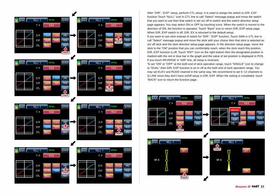
After “D/R”, “EXP” setup, perform CTL setup. It is used to assign the switch to D/R, EXP function Touch “NULL” icon in CTL line to call “Select” message popup and move the switch that you want to use then that switch is set on/ off to switch and the switch direction setup page appears. You may select ON or OFF by touching icons. When the switch is moved to the direction of ON, the function is operated. Touch “Back” icon to return D/R, EXP setup page. When D/R, EXP switch is off, D/R, EX is returned to the default setup.If you want to use stick instead of switch for “D/R”, “EXP” function, Touch SW6 in CTL line to call “Select” message popup and move the stick with your choice then that stick is selected as on/ off stick and the stick direction setup page appears. In the direction setup page, move the stick to the “ON” position that you can comfortably reach, when the stick reach this position, D/R, EXP function is off. Touch “ENT” icon on the right bottom then the designated position is marked with the red or blue bar in the graph and the value of set position is displayed in POS. If you touch REVERSE in “DIR” line, all setup is reversed. To set “ON” or “OFF” at the both end of stick operation range, touch “SINGLE” icon to change to “DUAL” then D/R, EXP function is on or off at the both end of stick operation range. You may set ELEV and RUDD channel in the same way. We recommend to set 5~12 channels to Q.LINK since they don’t have on/off setup in D/R, EXP. When the setting is completed, touch “BACK” icon to return the function page.

Touch
Touch
Touch
Touch
Touch
Touch
Touch
Touch Touch
Touch
Touch
32
Telemetry

Touch
Touch
Hold
ldle-up1
ldle-up2
ldle-up3
Touch
Touch
Touch
TRIM
TRIM TRIM
Touch
Touch
Touch
Touch
TRIM
TRIM
TRIM
TRIM
33
Telemetry
Telemetry
Telemetry
3. PIT.CRV
This function adjusts the pitch operation curve in relation to the movement of the throttle stick for each condition Since pitch curve is closely related with Q.LINK setup, Q.LINK setup should precede PIT.CRV setup. Call Q.LINK setup page and check Q.LINK setup is completed correctly and touch “BACK” icon to return FUNCTION page. (Refer to the manual on Q.LINK setup)
In FUNCTIOPN page, touch “PIT.CRV” icon to call PIT.CRV setup page. You need to mark the point on graph first and then adjust the operation curve with “DEC”, “INC”, X-axis and Y-axis buttons. Touch “ST OFF” to change to “ST ON” then the throttle position line appears on graph. Move throttle stick and place the line at the desired position between point “L” and “H” then touch “ENT” icon on the bottom right. Now the new point is marked in graph. You can mark five points between point “L” and “H” in the same way. Touch ST ON” to change to “ST OFF” and complete the point setup. Now touch “DEC” or “INC” button to select point and touch X-axis or Y-axis to activate and then touch DEC” or “INC” button to adjust the operation curve. Turn on the preset Q.LINK switch then you may adjust the operation curve of every Q.LINK as well.

Q.LINK (Hold)
Q.LINK (idel-up2)
Touch
Touch
TouchTouch
Touch
Touch
Touch
Touch
Touch
Touch
TRIM
TRIM
TRIM
TRIM
TRIM
TRIM
TRIM
TRIM
TRIM
TRIM
TRIM
TRIM
TRIM
TRIM
TRIM
34Telemetry
Touch
TRIM TRIM
35
TRIM
TouchTouch
Touch
Touch
Touch
Touch
Touch
+076%
+076%
TRIM
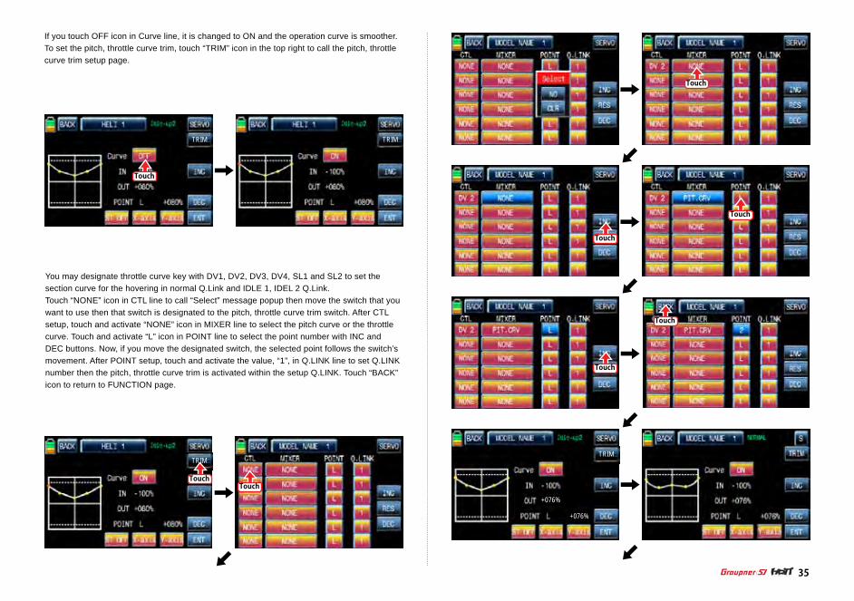
If you touch OFF icon in Curve line, it is changed to ON and the operation curve is smoother. To set the pitch, throttle curve trim, touch “TRIM” icon in the top right to call the pitch, throttle curve trim setup page.
You may designate throttle curve key with DV1, DV2, DV3, DV4, SL1 and SL2 to set the section curve for the hovering in normal Q.Link and IDLE 1, IDEL 2 Q.Link. Touch “NONE” icon in CTL line to call “Select” message popup then move the switch that you want to use then that switch is designated to the pitch, throttle curve trim switch. After CTL setup, touch and activate “NONE” icon in MIXER line to select the pitch curve or the throttle curve. Touch and activate “L” icon in POINT line to select the point number with INC and DEC buttons. Now, if you move the designated switch, the selected point follows the switch’s movement. After POINT setup, touch and activate the value, “1”, in Q.LINK line to set Q.LINK number then the pitch, throttle curve trim is activated within the setup Q.LINK. Touch “BACK” icon to return to FUNCTION page.
Touch
Touch
Touch
Touch
Touch
Touch Touch
Hold
ldle-up1
ldle-up2
ldle-up3
TRIM
TRIM
TRIM
TRIM
TRIM
36
Telemetry
Telemetry
Telemetry
Telemetry
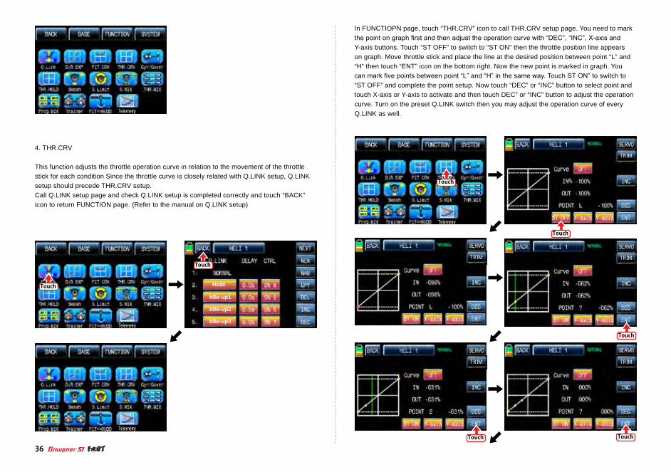
4. THR.CRV
This function adjusts the throttle operation curve in relation to the movement of the throttle stick for each condition Since the throttle curve is closely related with Q.LINK setup, Q.LINK setup should precede THR.CRV setup.Call Q.LINK setup page and check Q.LINK setup is completed correctly and touch “BACK” icon to return FUNCTION page. (Refer to the manual on Q.LINK setup)
In FUNCTIOPN page, touch “THR.CRV” icon to call THR.CRV setup page. You need to mark the point on graph first and then adjust the operation curve with “DEC”, “INC”, X-axis and Y-axis buttons. Touch “ST OFF” to switch to “ST ON” then the throttle position line appears on graph. Move throttle stick and place the line at the desired position between point “L” and “H” then touch “ENT” icon on the bottom right. Now the new point is marked in graph. You can mark five points between point “L” and “H” in the same way. Touch ST ON” to switch to “ST OFF” and complete the point setup. Now touch “DEC” or “INC” button to select point and touch X-axis or Y-axis to activate and then touch DEC” or “INC” button to adjust the operation curve. Turn on the preset Q.LINK switch then you may adjust the operation curve of every Q.LINK as well.

워드:63P63-5W 이미지 수정
Touch
Touch
Touch
Touch Touch
Touch
Touch
Touch
Touch
TRIM
TRIM
TRIM
TRIM
TRIM
TRIM
TRIMTRIM
TRIM
TRIM
TRIM TRIM
TRIM
TRIM
TRIM
37
Telemetry

S
TRIM
ON
MODEL NAME 1 NORMAL
+076%
+076%
Touch
Touch
TRIM
ON
HELI 1
+080%
+080%
TRIM
Y-ax i s
OFF
HELI 1
+100%
+082%H
Hold
ldle-up1
ldle-up2
ldle-up3
Touch
Touch
Touch
Touch
38
Touch
Touch
Touch
Touch
Touch
Telemetry
Telemetry
Telemetry
5. Gyr/Gover
This function is utilized to adjust the mixing of Gyro” and “Governor” for each condition. Since Gyr/Gover is closely related with Q.LINK setup, Q.LINK setup should precede Gyr/Gover setup.
If you touch OFF icon in Curve line, it is changed to ON and the operation curve is smoother. You may set the pitch, throttle curve trim by touching “TRIM” icon in the top right. The setup method is explained at PIT.CRV
Gyro Suppression TRIM Gyro Suppression TRIM
Touch
Touch
Touch
Touch
Touch
Touch
Gyro Suppression TRIM
Gyro Suppression TRIM
Gyro Suppression TRIM
Gyro Suppression TRIM
Gyro Suppression TRIMTouch
Touch
Gyro Suppression TRIM Gyro Suppression TRIM
Gyro Suppression TRIM Gyro Suppression TRIM
39
Telemetry
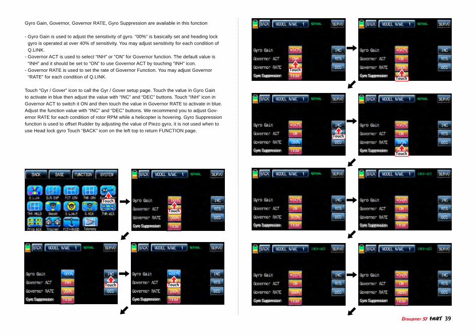
Gyro Gain, Governor, Governor RATE, Gyro Suppression are available in this function
- Gyro Gain is used to adjust the sensitivity of gyro. “00%” is basically set and heading lock gyro is operated at over 40% of sensitivity. You may adjust sensitivity for each condition of Q.LINK.
- Governor ACT is used to select “INH” or “ON” for Governor function. The default value is “INH” and it should be set to “ON” to use Governor ACT by touching “INH” icon.
- Governor RATE is used to set the rate of Governor Function. You may adjust Governor “RATE” for each condition of Q.LINK.
Touch “Gyr / Gover” icon to call the Gyr / Gover setup page. Touch the value in Gyro Gain to activate in blue then adjust the value with “INC” and “DEC” buttons. Touch “INH” icon in Governor ACT to switch it ON and then touch the value in Governor RATE to activate in blue. Adjust the function value with “INC” and “DEC” buttons. We recommend you to adjust Gov-ernor RATE for each condition of rotor RPM while a helicopter is hovering. Gyro Suppression function is used to offset Rudder by adjusting the value of Piezo gyro, it is not used when to use Head lock gyro Touch “BACK” icon on the left top to return FUNCTION page.

Touch
Gyro Suppression TRIM
TouchTouch
Touch
Touch
Touch
Touch
Touch
40
Telemetry
Telemetry
6. THR.HOLD
This function is for powering down an engine or motor using a designated switch. Throttle hold has higher authority than any other flight mode. When you activate THR.HOLD, the throttle channel is driven to its programmed value. It is usually used to turn off an engine or hold in idle position when helicopter’s auto rotation flight
In function page, touch “THR.HOLD” icon to call “THR.HOLD” setup page. Touch “INT” icon in ACT line to switch it on and touch “NULL” icon in CTL line to call “Select” message popup. Move the switch with your choice then that switch is designated as on/ off switch and the switch direction setup page appears. You may select ON or OFF by touching icons. When the switch is moved to the direction of ON, the function is operated. Touch “BACK” icon to return to “THR.HOLD” setup page again. Touch the default value, 17%, to activate in blue and adjust it with “INC” and “DEC” buttons. The red arrow indicates the value for each value. When “THR.HOLD” function is on, the green arrow is positioned in the setup value. After setup, touch “BACK” icon to return FUNCTION page.

Touch
Touch
Touch
Touch
Touch
Touch
Touch
Touch
41
Telemetry
Telemetry Telemetry
7. SWASH
The swash function supports adjustment of the travel amount and direction of the aileron, elevator and pitch in Helicopter mode. Bind a helicopter to a receiver and set the travel amount and direction of the swash channels desirably Touch “SWASH” icon to call “SWASH” setup page. When touching the values in PITC, AILE and ELEV, they are activated in blue. You may adjust the values with INC and DEC buttons. The default value is 60%. If the minus value is programmed, the travel direction of the swash channel is reversed. You may watch the servo operation by touching “ SERVO” icon in the right top. Touch “BACK” icon to return to the function page.

Touch
Touch
Touch
Touch
Touch
Touch
Touch
42
Telemetry
Telemetry
8. S.Limt (Swash Limit)
It is used to have the channels of PITCH, AILE and ELEV operated for the circle movement of the stick and the channels of PITCH, AILE and EL have the travel limits according to the circle setup size. Servo EPA should be set over 100%, if the circle size is over 100%
9. S.MIX (Swash mixing)
S.MIX typically corrects swash plate timing issues by mixing AILE>>ELEV, ELEV>>AILE, PITC>>AILE, PITC>>ELEV. This function can be adjusted for each condition of Q.LINK.
AILE>>ELEV: It is used when a helicopter tends to be UP or DOWN while controlling aileron.ELEV>>AILE: It is used when a helicopter tends to bank to left or right while controlling elevator.PITC >>AILE: It is used when a helicopter tends to bank to left or right while controlling pitch. PITC >>ELEV: It is used when a helicopter tends to be UP or DOWN while controlling pitch.
In function page, touch “S.MIX” icon to call S.MIX setup page. Touch “INH” icon in ACT line to switch to “ON” and touch >> icon to call the mixing setup page. Touch and activate the values in LEFT and RIGHT line and adjust the mixing value with “INC” and “DEC” buttons. The pro-grammed values are indicated in the left graph. The soft or rough movement can be adjusted by touching the values in EXP line, (+) value will make it smoothly and (-) value will make it roughly. You may watch the servo operation by touching “ SERVO” icon in the right top. Touch “BACK” icon to return to S.MIX setup page. Now, you need to set CTL function. Touch “On” icon to call “Select” message popup then move the switch with your choice then that switch is designated as on/ off switch and then the switch direction setup page appears. You may select ON or OFF by touching icons. When the switch is moved to the direction of ON, the function is operated. Touch “BACK” icon to return to S.MIX setup page and confirm the setup data. Touch “BACK” icon to return to FUNCTION page
The Swash rotation function in the bottom is used to make the swash that mz-12 doesn’t support available by rotating the swash angleIn the Function page, touch “S.Limit” icon to call “S.Limit” setup page. Touch “INH” icon in “ACT” line to switch to “ON” then the default value, 100% sized circle appears. Now, touch “100%” icon in SET line to activate in blue. Adjust the cirvle size with “INC” and “DEC” buttons. Touch “00’” icon in “Swash rotation” in the bottom to activate in blue then the swash angle is set with “INC” and “DEC” buttons. Touch “BACK” icon to return to “FUNC-TION” page.

Telemetry
Touch
Touch
Touch
Touch Touch
A (RATE) B
A (RATE) B A (RATE) B
Touch
Touch
Touch
Touch
Touch
Touch
Touch
Touch
A (RATE) B
A (RATE) B
A (RATE) B
A (RATE) B
A (RATE) B
43
Touch Touch

Touch
Touch
Touch
Touch
Touch Touch
A (RATE) B
A (RATE) B A (RATE) B
Touch
Touch
A (RATE) B A (RATE) B
44
Telemetry Telemetry
10. THR.MIX
THR.MIX function prevents RPM decay when PITCH, AILE and ELEV inputs are given. This mix advances the throttle position with mix control to maintain RPM. This function can be adjusted for each condition of Q.LINK and three types is available (AILE>>THRO, ELEV>>THRO, RUDD>>THRO)
AILE>>THRO: It can prevent RPM decay and maintain flight altitude of a helicopter while controlling aileron.ELEV>>THRO: It can prevent RPM decay and maintain flight altitude of a helicopter while controlling elevator.RUDD>>THRO: It can prevent RPM decay and maintain flight altitude of a helicopter when the rudder pitch is changed by controlling rudder
In FUNCTION page, touch “THR.MIX” icon to call THR.MIX setup page. Touch “INH” icon in ACT line to switch to “ON” and touch >> icon to call the mixing setup page. Touch and activate the values in LEFT and RIGHT line and adjust the mixing value with “INC” and “DEC” buttons. The programmed values are indicated in the left graph. You may watch the servo operation by touching “ SERVO” icon in the right top. Touch “BACK” icon to return to THR.MIX setup page. Now, you need to set CTL function. Touch “On” icon to call “Select” message popup then move the switch with your choice then that switch is designated as on/ off switch and then the switch direction setup page appears. You may select ON or OFF by touching icons. When the switch is moved to the direction of ON, the function is operated. Touch “BACK” icon to return to THR.MIX setup page then confirm the setup data. Touch “BACK” icon to return to FUNCTION page
Touch
Touch
Touch
Touch
45
Telemetry
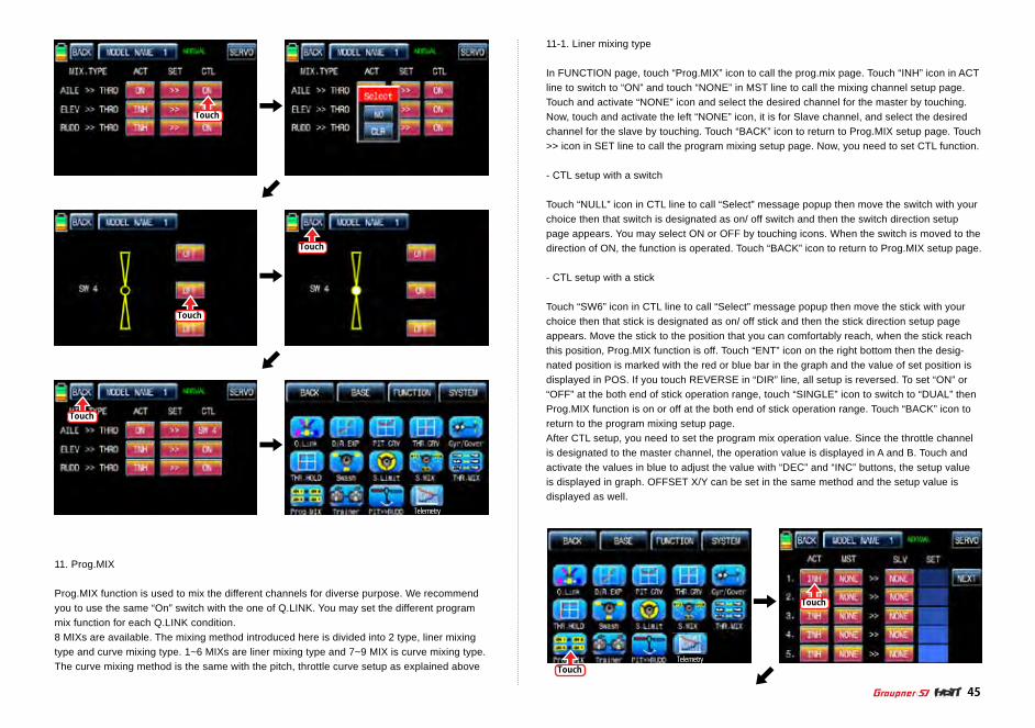
11. Prog.MIX
Prog.MIX function is used to mix the different channels for diverse purpose. We recommend you to use the same “On” switch with the one of Q.LINK. You may set the different program mix function for each Q.LINK condition. 8 MIXs are available. The mixing method introduced here is divided into 2 type, liner mixing type and curve mixing type. 1~6 MIXs are liner mixing type and 7~9 MIX is curve mixing type. The curve mixing method is the same with the pitch, throttle curve setup as explained above
11-1. Liner mixing type
In FUNCTION page, touch “Prog.MIX” icon to call the prog.mix page. Touch “INH” icon in ACT line to switch to “ON” and touch “NONE” in MST line to call the mixing channel setup page. Touch and activate “NONE” icon and select the desired channel for the master by touching. Now, touch and activate the left “NONE” icon, it is for Slave channel, and select the desired channel for the slave by touching. Touch “BACK” icon to return to Prog.MIX setup page. Touch >> icon in SET line to call the program mixing setup page. Now, you need to set CTL function.
- CTL setup with a switch
Touch “NULL” icon in CTL line to call “Select” message popup then move the switch with your choice then that switch is designated as on/ off switch and then the switch direction setup page appears. You may select ON or OFF by touching icons. When the switch is moved to the direction of ON, the function is operated. Touch “BACK” icon to return to Prog.MIX setup page.
- CTL setup with a stick
Touch “SW6” icon in CTL line to call “Select” message popup then move the stick with your choice then that stick is designated as on/ off stick and then the stick direction setup page appears. Move the stick to the position that you can comfortably reach, when the stick reach this position, Prog.MIX function is off. Touch “ENT” icon on the right bottom then the desig-nated position is marked with the red or blue bar in the graph and the value of set position is displayed in POS. If you touch REVERSE in “DIR” line, all setup is reversed. To set “ON” or “OFF” at the both end of stick operation range, touch “SINGLE” icon to switch to “DUAL” then Prog.MIX function is on or off at the both end of stick operation range. Touch “BACK” icon to return to the program mixing setup page.After CTL setup, you need to set the program mix operation value. Since the throttle channel is designated to the master channel, the operation value is displayed in A and B. Touch and activate the values in blue to adjust the value with “DEC” and “INC” buttons, the setup value is displayed in graph. OFFSET X/Y can be set in the same method and the setup value is displayed as well.
Touch
TouchTelemetry

Touch
Touch
Touch
Touch
Touch
ACT
A
CTL
B
Touch
Touch
Touch
Touch
Touch
CTL
B
Touch
Touch
46

Touch
Touch
Touch
Touch
ACT
A
CTL
B
ACT
A
CTL
B
ACT
A
CTL
B
ACT
A
CTL
B
Touch
Touch
Touch
Touch
Touch
Touch
Touch
Touch
ACT
A
CTL
B
ACT
A
CTL
B
ACT
A
CTL
B
ACT
A
CTL
B
ACT
A
CTL
B
ACT
A
CTL
B
47
Telemetry

48
Touch
Touch
Touch
Touch
Touch
Touch
Touch
Touch
Touch
Touch
11-2. Curve mixing type
In the prog.mix page, touch “NEXT” icon to call the next page and touch “INH” icon in the cross line of NO7 and ACT to switch to “ON”. Touch “NONE” in MST line to access the channel selection page and touch and activate “NONE” icon to select the desired channel of MST and SLV. Touch “BACK” icon to return to the prog.mix page. Touch “>>” icon to call the program mixing setup page. Now, you need to set CTL function.
- CTL setup with a switch
Touch “ON” icon in CTL line to call “Select” message popup then move the switch with your choice then that switch is designated as on/ off switch and then the switch direction setup page appears. You may select ON or OFF by touching icons. When the switch is moved to the direction of ON, the function is operated. Touch “BACK” icon to return to the program mixing setup page.
- CTL setup with a stick
Hoping that you would refer the explanation as explained above
Here, you need to set the operation value, “L” and “H” points are set by default and you need to mark 5 points between “L” and “H” on graph first and then adjust the operation curve with “DEC”, “INC”, X-axis and Y-axis buttons. Touch “ST OFF” icon to switch to “ST ON” then the blue line appears on graph. Move the designated switch or stick to place the line at the desired position then touch “ENT” icon on the bottom right. Now the new point is marked in graph. You may set five points in your favorable position.Touch “PITT >> RUDD” icon in the function page to call PIT >> RUDD setup page. You need to mark the point on graph first and then adjust the operation curve with “DEC”, “INC”, X-axis and Y-axis buttons. Touch “ST OFF” icon to switch to “ST ON” then the pitch position line appears on graph. Move throttle stick and place the line at the desired position between point “L” and “H” then touch “ENT” icon on the bottom right. Now the new point is marked in graph. Touch ST ON” to switch to “ST OFF” and complete the point setup. Now touch “DEC” or “INC” button to select point and touch X-axis or Y-axis to activate and then touch DEC” or “INC” button to adjust the operation curve.

49
Touch
Touch
Touch
Touch
Touch Touch
Touch
Touch
Touch
Touch
Touch
Touch
Touch
Touch
Touch
Touch
Touch
Touch
Touch
50
Touch
Telemetry
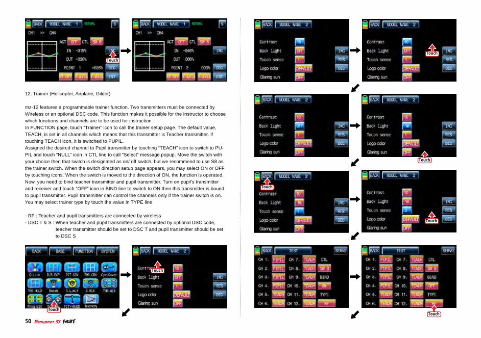
12. Trainer (Helicopter, Airplane, Gilder)
mz-12 features a programmable trainer function. Two transmitters must be connected by Wireless or an optional DSC code. This function makes it possible for the instructor to choose which functions and channels are to be used for instruction.In FUNCTION page, touch “Trainer” icon to call the trainer setup page. The default value, TEACH, is set in all channels which means that this transmitter is Teacher transmitter. If touching TEACH icon, it is switched to PUPIL.Assigned the desired channel to Pupil transmitter by touching “TEACH” icon to switch to PU-PIL and touch “NULL” icon in CTL line to call “Select” message popup. Move the switch with your choice then that switch is designated as on/ off switch, but we recommend to use S8 as the trainer switch. When the switch direction setup page appears, you may select ON or OFF by touching icons. When the switch is moved to the direction of ON, the function is operated. Now, you need to bind teacher transmitter and pupil transmitter. Turn on pupil’s transmitter and receiver and touch “OFF” icon in BIND line to switch to ON then this transmitter is bound to pupil transmitter. Pupil transmitter can control the channels only if the trainer switch is on. You may select trainer type by touch the value in TYPE line.
- RF : Teacher and pupil transmitters are connected by wireless - DSC T & S : When teacher and pupil transmitters are connected by optional DSC code,
teacher transmitter should be set to DSC T and pupil transmitter should be set to DSC S

Touch
TouchTouch
Touch
Touch
Touch
Touch
Touch
51
Telemetry
13. PIT >>RUDD
This function is used to correct the unintended movement of rudder during the flight of a helicopter. It is not necessary when you make use of heading lock gyroTouch “PITT >> RUDD” icon in the function page to call PIT >> RUDD setup page. You need to mark the point on graph first and then adjust the operation curve with “DEC”, “INC”, X-axis and Y-axis buttons. Touch “ST OFF” icon to switch to “ST ON” then the pitch position line appears on graph. Move throttle stick and place the line at the desired position between point “L” and “H” then touch “ENT” icon on the bottom right. Now the new point is marked in graph.
By moving the pitch bar with the throttle stick, you should fix the bar in the desired position between L and H point. Now, touch the “ENT” icon on the bottom right side and then the new point will appear. You may set five points in your favorable position.
You need to mark the point on graph first and then adjust the operation curve with “DEC”, “INC”, X-axis and Y-axis buttons. Touch “ST OFF” to change to “ST ON” then the throttle position line appears on graph. Move throttle stick and place the line at the desired position between point “L” and “H” then touch “ENT” icon on the bottom right. Now the new point is marked in graph. You can mark five points between point “L” and “H” in the same way. Touch ST ON” to switch to “ST OFF” and complete the point setup. Now touch “DEC” or “INC” button to select point and touch X-axis or Y-axis to activate and then touch DEC” or “INC” button to adjust the operation curve. Turn on the preset Q.LINK switch then you may adjust the opera-tion curve of every Q.LINK as well.

Touch
Touch
Touch
Touch
Touch
Touch
Touch
Touch
Touch
Touch
Touch
Touch
Touch
52
Telemetry
14. Telemetry
It is used to perform the programming setup and check HoTT telemetry functions. Touch “Telemetry” icon to call the Telemetry page. You may program 5 types of “RX SELECT”, “SET-TING & DATA VIEW” “SENSOR SELECT”, ”RF STATUS VIEW”, and “VOCIE TRIGGER”.
14-1. RX SELECT
It is used to select a receiver that would transmit the telemetry data to mz-12 when 2 receivers are bound to mz-12. All of the telemetry sensors should be connected to the selected receiver. RX1” is set in RX SELECT line as a default and “RX1” and “RX2” can be switch by touching.

Telemetry
53
Touch
Touch
Touch
Touch
Touch
Touch
Touch
Touch
14-2. SETTING & DATA VIEW
It is used to program or check telemetry data of a receiver and telemetry sensors. Only if trans-mitter and receiver are bound, SETTING & DATA VIEW function is activated. Touch “>>” icon in the telemetry setup page to call “RX DATA VIEW” setup page
- RX DATA VIEW
You may check telemetry data of a receiver in this page. Touch “ENT” icon to access to the next function, “RX SERVO” page.
- RX SERVO
The servo functions, “REVERSE”, “CENTER”, “TRIM”,” LIMIT-“, LIMIT+, and “PERIOD”, can be programmed throughout receiver when servo is connected to each channel of receiver.In “RX DATA VIEW” page, touch “ENT” icon to call RX SERVO page. You may move the cursor “>” to other category with INC button and select the category that you want to program. After deciding the desired category, touch “SET” icon to activate in red and adjust the value with INC and DEC buttons.
• OUTPUT CH
The receiver’s out channel is programmed in OUTPUT CH line. Touch “SET” icon to activate the value in red and select the desired channel with INC and DEC buttons. Touch “SET” icon again to deactivate the value and touch INC button to move the cursor to “Reverse”.
Touch
Touch
Touch
Touch
Touch
Touch
Touch
54
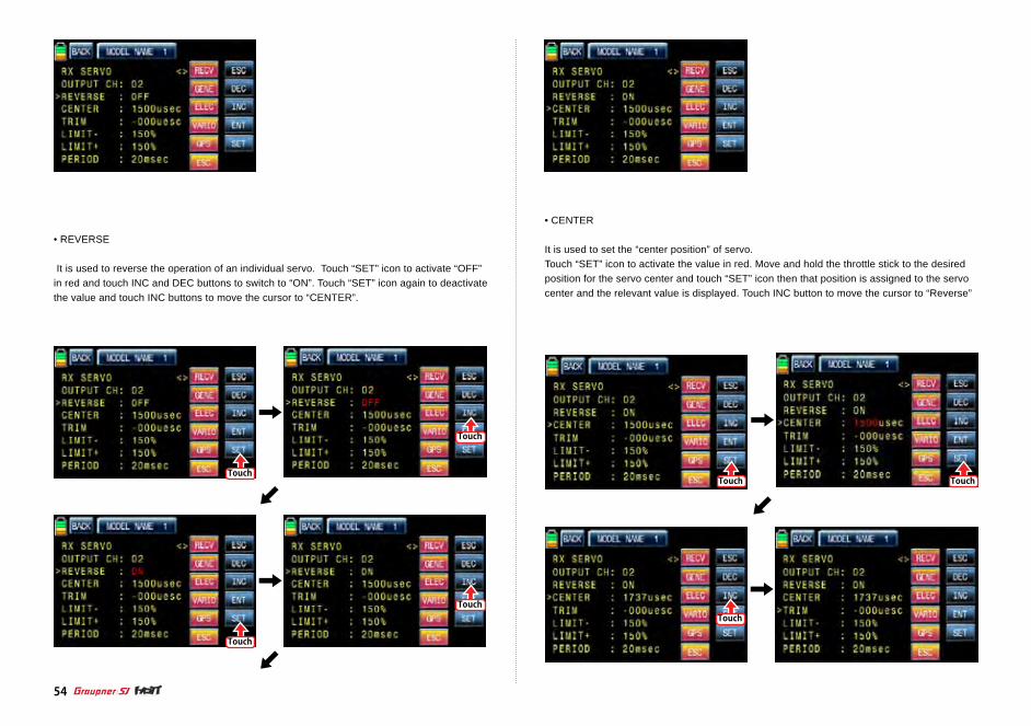
• REVERSE
It is used to reverse the operation of an individual servo. Touch “SET” icon to activate “OFF” in red and touch INC and DEC buttons to switch to “ON”. Touch “SET” icon again to deactivate the value and touch INC buttons to move the cursor to “CENTER”.
• CENTER
It is used to set the “center position” of servo.Touch “SET” icon to activate the value in red. Move and hold the throttle stick to the desired position for the servo center and touch “SET” icon then that position is assigned to the servo center and the relevant value is displayed. Touch INC button to move the cursor to “Reverse”

Touch
Touch
Touch
Touch
Touch
Touch
Touch
Touch
Touch
55
• TRIM
It is used to set the servo’s “Trim position”.Touch “SET” icon then the values of CENTER and TRIM are activated in red. Adjust TRIM values with INC and DEC buttons and touch “SET” icon again to deactivate the value. Touch INC button to move the cursor to “LIMIT -”
NOTICE: When TRIM value is adjusted, the default value of CENTER, 1500usec, is automati-cally set and the trim setup value is added to 1500usec.
• LIMIT -, +
The function supports the adjustment of servo’s maximum travel amount for +,- direction.Even the default value is 150%, the travel amount is limited to 100% that is programmed at SERVO EPA of transmitter so 100%~150% range cannot be programmed and under 100% range can be only programmed at “ LIMIT–“. Only if SERVO EPA of transmitter is set to “150%”, you can set below 150% at LIMIT- value. Touch “SET” icon to activate the value in red and adjust the value with INC and DEC buttons. Touch “SET” icon again to deactivate the value and touch INC button to move the cursor to “PERIOD”.

Touch
Touch
Touch
Touch
Touch
Touch
Touch
Touch
56
• PERIOD
It is used to set the speed of receiver’s output signal. Touch “SET” icon to activate the default value, 20msec, in red and set the value to 10msec with INC and DEC buttons. Touch “SET” icon again to deactivate the value and touch ENT button to call “RX FAIL SAFE” setup page
- RX FAIL SAFE
• OUTPUT CH/ INPUT CH
You may edit and adjust transmitter channel which is connected with a receiver using “OUT-PUT CH” and “INPUT CH”. Receiver CH1, 2, 3, 4, 5, 6 are connected to the same channels of transmitter as the default and you may edit the channel connection of receiver and transmitter. Since OUTPUT CH is changed if INPUT CH would be changed, we recommend that you would change INPUT CH.Touch INC button to move the cursor to “INPUT CH” and touch “SET” icon to activate the value in red then select the channel to be connected to “OUTPUT CH” with INC and DEC buttons. Touch “SET” icon again to deactivate the value. Touch INC button to move the cursor to “MODE”

Touch
Touch
Touch
Touch
Touch
Touch
Touch
Touch
Touch
Touch
57
• MODE
It is used to select the failsafe type. “HOLD” is basically set in all the channels.Touch “SET” icon to activate the value in red then you may select HOLD or OFF or FAIL SAFE with INC and DEC buttons. After selecting one of HOLD, OFF and FAIL SAFE, touch “SET” icon again to deactivate the value. Touch INC button to move the cursor to “F.S.POS”
• F.S.POS
It is used to decide the servo’s position when FAIL SAFE function is activated. Touch “SET” icon to activate the value in red and adjust the value with INC and DEC buttons. Touch “SET” icon again to deactivate the value. Touch INC button to move the cursor to “DELAY”

Touch
Touch
Touch
Touch
Touch
Touch
Touch
58
• DELAY
It is used to set the time delay. The failsafe will delay for the setup time.Touch “SET” icon to activate the value in red and adjust the value with INC and DEC buttons. Touch “SET” icon again to deactivate the value. Touch INC button to move the cursor to “FAIL SAFE ALL”
• FAIL SAFE ALL
This function allows that all failsafe position for every channel can be set at a time without the use of F.S.POS function. Notice that MODE of all channels should be set to FAIL SAFE.Touch “SET” icon to activate the value, NO, in red and move and hold the throttle stick to the desired position for FAIL SAFE operation position. Touch “SET” icon then that position is assigned to FAIL SAFE operation position and the relevant value is displayed in F.S.POS line. The servo that is connected to receiver is operated to the set position of FAIL SAFE when transmitter is turned off Touch INC button to move the cursor to “POSITION”
• POSITION
You may check the operation range of transmitter’s stick which is connected with “INPUT CH”.Touch “ENT” icon on the right to access to the next page, “RX FREE MIXER”.

Touch
Touch
Touch
Touch
Touch
Touch
Touch
Touch
59
- RX FREE MIXER
This function is used to correct the unintended movement of airplane during the flight by mixing master channel and slave channel.
• MIXERYou may decide MIXER number that you want to set. Touch “SET” icon to activate the value in red and select MIXER number with INC and DEC buttons. Touch “SET” icon again to deacti-vate the value. Touch INC button to move the cursor to “MASTER CH”
• MASTER CH
You may set the master channel of FREE MIXER. Touch “SET” icon to activate the value in red and select the master channel number with INC and DEC buttons. Touch “SET” icon again to deactivate the value. Touch INC button to move the cursor to “SLAVE CH”
• SLAVE CH
You may set the salve channel of FREE MIXER. Touch “SET” icon to activate the value in red and select the slave channel number with INC and DEC buttons. Touch “SET” icon again to deactivate the value. Touch INC button to move the cursor to “S-TRAVEL-”

Touch
Touch
Touch
Touch
Touch
Touch
Touch
Touch
Touch
Touch
Touch
60
• “S-TRAVEL -, +” It is used to set the mix operation range of SLAVE CH. Touch “SET” icon to activate the value in red and select the slave channel number with INC and DEC buttons. Touch “SET” icon again to deactivate the value. If you operate the master channel, the slave channel is operated within the setup range at the same time. Touch INC button to move the cursor to “TAIL TYPE”

Touch
Touch
Touch
Touch
Touch
Touch
Touch
Touch
61
• TAIL TYPE
You may select the appropriate tale type for the airplane that you useTouch “SET” icon to activate the value in red and select the appropriate tale type with INC and DEC buttons. Touch “SET” icon again to deactivate the value. Touch “ENT” icon on the right to access to the next page, “RX CURVE”,
- RX CURVE
It is used to set the curve of CH2, CH3, and CH4 and 3 types of A, B, and C are selectable.
> A type : Sensitive operating> B type : Normal operating> C type : smooth operating
The default, B type is set and it is very similar with “EXP” function of transmitter. You may transfer the cursor, >, with INC and DEC buttons and can select the desired category. Touch “SET” icon to activate the value in red and select the channel and type with INC and DEC buttons. Touch “SET” icon again to deactivate the value. If you operate the master chan-nel, the slave channel is operated within the setup range at the same time. Touch “ENT” icon on the right to access to the next page, “RX SERVO TEST”,

Touch
Touch
Touch
Touch
Touch
Touch
Touch
Touch
Touch
Touch
Touch
Touch
62
- RX SERVO TEST This function allows servo operation to be tested and program the receiver’s power voltage, the alarm for the maximum/minimum temperature of receiver and the channel out type of receiver.
• ALL-MAX/ ALL-MIN/ TEST
The travel amount for servo test is decided for the setup value of ALL-MAX and ALL-MIN Touch “SET” icon to activate the value of ALL-MAX and ALL-MIN in red and adjust the value with INC and DEC buttons. Touch “SET” icon again to deactivate the value. Transfer the cursor to TEST line and touch “SET” icon to activate the value, STOP, in red. Now, switch to START with INC and DEC buttons and touch “SET” icon again to deactivate the value then all servos con-nected to receiver are slowly operated within the setup. if you set to STOP by touching “SET” and “INC/DEC” icons, all servos stop operating. Touch INC button to move the cursor to “TAIL TYPE”
Touch “SET” icon again to deactivate the value. If you operate the master channel, the slave channel is operated within the setup range at the same time. Touch INC button to move the cursor to “ALARM VOLT”,

Touch
Touch Touch
Touch
Touch
Touch
Touch
Touch
Touch
Touch
Touch
63
• ALARM VOLT
It is the low voltage alarm setup for receiver power battery. Transmitter sounds an alarm throughout telemetry technology when the battery of receiver reaches the low voltage limit.Touch “SET” icon to activate the value in red and adjust the value with INC and DEC buttons. Touch “SET” icon again to deactivate the value. Touch INC button to move the cursor to “ALARM TEMP+”

Touch
Touch
Touch
Touch
Touch
Touch
Touch
Touch
64
• ALARM TEMP +/-
It is the alarm setup for the maximum/minimum temperature of receiver. Transmitter sounds an alarm throughout telemetry technology when the temperature of receiver reaches the temperature limits.Touch “SET” icon to activate the value in red and adjust the value with INC and DEC buttons. Touch “SET” icon again to deactivate the value. Touch INC button to move the cursor to “CH OUT TYPE”
- CH OUT TYPE
It is used to set the type of receiver’s signal output and it consists of ONCE, SAME, SUMO 12, SUMI, and SUMD HD12.
> ONCE : This type is applied to the analog servo. “20msec” is automatically set to PERIOD in RX SERVO setup
> SAME : This type is usually applied to the digital servo. You need to “10 ~ 20msec” to PERIOD. In case that the analog servo is connected, you need to set “20msec” to PERIOD.
> SUMI : The receiver set to SUMI take the output signal from the receiver set to SUMO and outputs the signal.
> SUMO : Only the selected channel outputs the signal of all channels of receiver. In case that 1 receiver is set to SUMO and the other receiver is set to SUMI and then they are connected in ex code, the receiver set to SUMI take the output signal from the re-ceiver set to SUMO and it is operated at the same time. The final channel of receiver is the output channel of SUMO, but you may change to the desired channel.
> SUMD HD : The digital output signal of all channels in receiver is outputted from the select-ed channel. It is used to the product that needs the receiver digital signal such as Power box and Flybarless system. The factory default for SUMD HD output channel is the last channel of receiver, but you may change it

Touch
Touch
Touch
Touch
Touch
Touch
Touch
TouchTouch
Touch
Touch
65
Touch “SET” icon to activate the value in red and select the desired type with INC and DEC buttons. Touch “SET” icon again to deactivate the value. Touch INC button to move the cursor to “CH OUT TYPE” In order to set for CH OUT TYPE, touch “INC” icon to move the cursor to CH OUT TYPE and then touch the “SET” icon. Now, “SAME” in CH OUT TYPE is activated in a red. When it is activated, touch the INC or DEC icons to select the desirable receiver type and then touch the “SET” icon to remove the cursor. The set type of receiver is activated. When you select SUMO 8 and SUMD HD8 and try to select the different output channel, touch “SET” icon to activate the channel number in red then select the desired channel with INC and DEC buttons. Touch “SET” icon again to deactivate the value. Now, the selected channel outputs PPM signal.
14-3. SENSOR SELECT
This function is used to program telemetry sensor that is connected to HoTT receiver.You should select the sensor first to use and program the function such as voice function, warning and the telemetry data information. Touch “>>” icon in SENSOR SELECT line then RECEIVER, GENERAL MODULE, ELECTRIC AIR, MOD, VARIO MODULE, GPS, and ESC are displayed. RECEIVER is set to ON, the others are set to OFF by default. To select the sensor, touch “OFF” icon to switch to “ON” then voice function, warning and the telemetry data information are available. After the sensor selection is completed, touch “BACK” icon to return to the previous page.

Touch
Touch
Touch
Touch
Touch
Touch
Touch
66
14-4. RF STATUS VIEW
It shows RF status between transmitter and receiver throughout telemetry functionTouch “>>” icon in RF STATUS VIEW line then the indication to show the RF connection status is displayed by graph.
14-5. VOCIE TRIGGER
It is used to program the sensors related with voice function. REPEAT, TRIG, VARIO, TRANS-SMITTER, RECEIVER are available by default and the optional sensors could be attached. If the optional sensor is connected, it is need to add the optional sensor at SENSOR SELECT mode then new category in VOICE TRIGGER is created. The useable sensors are GENERAL MODULE, ELECTRIC AIR MODULE, VARIO MODULE, GPS, AIR ESCTouch “>>” icon in VOICE TRIGGER line to call “VOICE TRIGGER” setup page.
- REPEAT
You may set the time and select the switch. If the switch is on, one of voice functions is repeated for the setup time.Touch the value, “01s”, in blue and adjust the repeat time with INC and DEC buttons. Touch “NULL” icon to call the “Select” message popup. Move the switch or volume with your choice then that switch or volume is designated as on/ off key and then the key direction setup page appears. You may select ON or OFF by touching icons. When the key is moved to the direction of ON, the function is operated. Touch “BACK” icon to return to “VOICE TRIGGER” setup page.
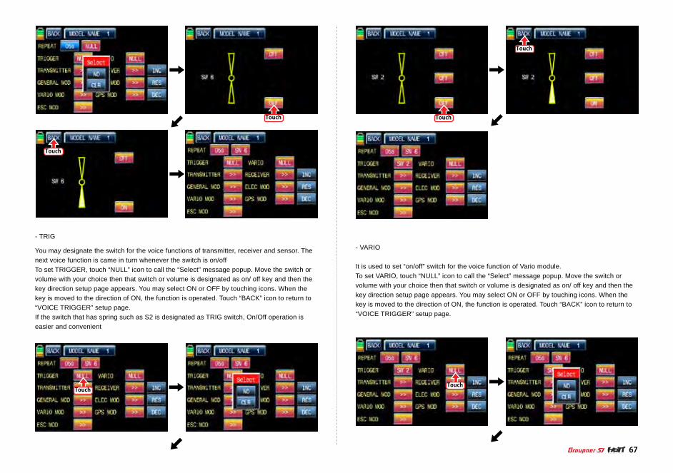
Touch
Touch
Touch
Touch
Touch
Touch
67
- TRIG
You may designate the switch for the voice functions of transmitter, receiver and sensor. The next voice function is came in turn whenever the switch is on/offTo set TRIGGER, touch “NULL” icon to call the “Select” message popup. Move the switch or volume with your choice then that switch or volume is designated as on/ off key and then the key direction setup page appears. You may select ON or OFF by touching icons. When the key is moved to the direction of ON, the function is operated. Touch “BACK” icon to return to “VOICE TRIGGER” setup page.If the switch that has spring such as S2 is designated as TRIG switch, On/Off operation is easier and convenient
- VARIO
It is used to set “on/off” switch for the voice function of Vario module.To set VARIO, touch “NULL” icon to call the “Select” message popup. Move the switch or volume with your choice then that switch or volume is designated as on/ off key and then the key direction setup page appears. You may select ON or OFF by touching icons. When the key is moved to the direction of ON, the function is operated. Touch “BACK” icon to return to “VOICE TRIGGER” setup page.

Touch
Touch Touch
Touch
- RECEIVER
수신기의 텔레메트리VOICE기능 TEMP, STRENGTH, RX VOLT, LOW VOLT 4가지 VOICE기능의 사용을 편집하는 기능입니다.RECIVER기능을 설정하려면 RECIVER기능의 >>를 터치하면 RECIVER 설정화면으로 이동합니다.RECIVER기능으로 이동하면 TEMP, STRENGTH, RX VOLT, LOW VOLT 4가지 RECIVER VOICE기능이 기본으로 빨간색으로 체크되어 있습니다. 사용하고 싶지 않은 기능을 터치하면 빨간색 체크가 흰색으로 해제되고 RECIVER VOICE기능에서 편집 됩니다. RECIVER기능설정이 끝나면 좌측상단의 BACK를 터치하면 VOICE TRIGGER기능 설정화면으로 이동합니다.
Touch
Touch
- TRANSSMITTER
송신기의 텔레메트리VOICE기능 TX VOLT, MODEL TIME, BATT TIME, TIMER 1, TIMER 2, CUR-RENT TIME 6가지 VOICE기능의 사용을 편집하는 기능입니다.TRANSSMITTER기능을 설정하려면 TRANSSMITTER기능의 >>를 터치하면TRANSSMITTER 설정화면으로 이동합니다. TRANSSMITTER기능으로 이동하면 TX VOLT, MODEL TIME, BATT TIME, TIMER 1, TIMER 2, CURRENT TIME 6가지 TRANSSMITTER VOICE기능이 기본으로 빨간색으로 체크되어 있습니다. 사용하고 싶지 않은 기능을 터치하면 빨간색 체크가 흰색으로 해제되고 TRANSSMIT-TER VOICE기능에서 편집 됩니다. TRANSSMITTER기능설정이 끝나면 좌측상단의 BACK를 터치하면 VOICE TRIGGER기능 설정화면으로 이동합니다.
Touch
Touch
68
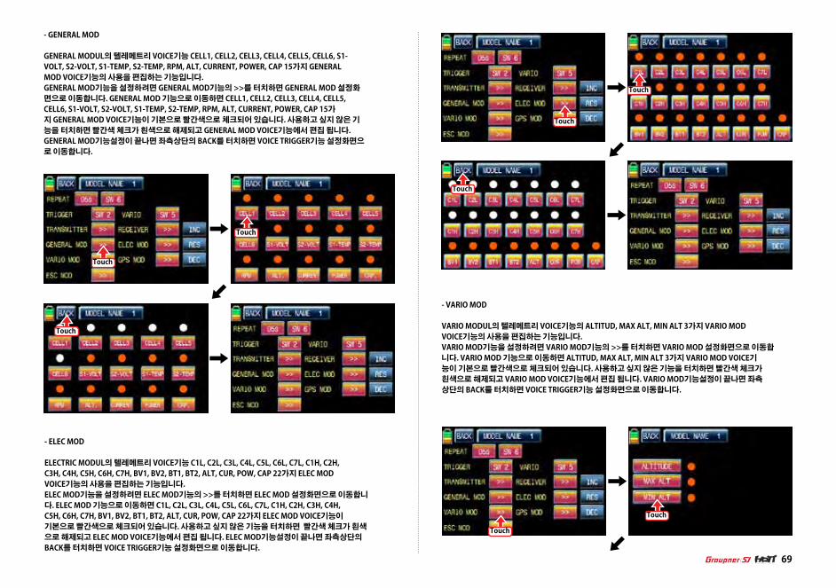
- GENERAL MOD
GENERAL MODUL의 텔레메트리 VOICE기능 CELL1, CELL2, CELL3, CELL4, CELL5, CELL6, S1-VOLT, S2-VOLT, S1-TEMP, S2-TEMP, RPM, ALT, CURRENT, POWER, CAP 15가지 GENERAL MOD VOICE기능의 사용을 편집하는 기능입니다.GENERAL MOD기능을 설정하려면 GENERAL MOD기능의 >>를 터치하면 GENERAL MOD 설정화면으로 이동합니다. GENERAL MOD 기능으로 이동하면 CELL1, CELL2, CELL3, CELL4, CELL5, CELL6, S1-VOLT, S2-VOLT, S1-TEMP, S2-TEMP, RPM, ALT, CURRENT, POWER, CAP 15가지 GENERAL MOD VOICE기능이 기본으로 빨간색으로 체크되어 있습니다. 사용하고 싶지 않은 기능을 터치하면 빨간색 체크가 흰색으로 해제되고 GENERAL MOD VOICE기능에서 편집 됩니다. GENERAL MOD기능설정이 끝나면 좌측상단의 BACK를 터치하면 VOICE TRIGGER기능 설정화면으로 이동합니다.
- ELEC MOD
ELECTRIC MODUL의 텔레메트리 VOICE기능 C1L, C2L, C3L, C4L, C5L, C6L, C7L, C1H, C2H, C3H, C4H, C5H, C6H, C7H, BV1, BV2, BT1, BT2, ALT, CUR, POW, CAP 22가지 ELEC MOD VOICE기능의 사용을 편집하는 기능입니다.ELEC MOD기능을 설정하려면 ELEC MOD기능의 >>를 터치하면 ELEC MOD 설정화면으로 이동합니다. ELEC MOD 기능으로 이동하면 C1L, C2L, C3L, C4L, C5L, C6L, C7L, C1H, C2H, C3H, C4H, C5H, C6H, C7H, BV1, BV2, BT1, BT2, ALT, CUR, POW, CAP 22가지 ELEC MOD VOICE기능이 기본으로 빨간색으로 체크되어 있습니다. 사용하고 싶지 않은 기능을 터치하면 빨간색 체크가 흰색으로 해제되고 ELEC MOD VOICE기능에서 편집 됩니다. ELEC MOD기능설정이 끝나면 좌측상단의 BACK를 터치하면 VOICE TRIGGER기능 설정화면으로 이동합니다.
Touch
Touch
Touch
Touch
Touch
Touch
- VARIO MOD
VARIO MODUL의 텔레메트리 VOICE기능의 ALTITUD, MAX ALT, MIN ALT 3가지 VARIO MOD VOICE기능의 사용을 편집하는 기능입니다.VARIO MOD기능을 설정하려면 VARIO MOD기능의 >>를 터치하면 VARIO MOD 설정화면으로 이동합니다. VARIO MOD 기능으로 이동하면 ALTITUD, MAX ALT, MIN ALT 3가지 VARIO MOD VOICE기능이 기본으로 빨간색으로 체크되어 있습니다. 사용하고 싶지 않은 기능을 터치하면 빨간색 체크가 흰색으로 해제되고 VARIO MOD VOICE기능에서 편집 됩니다. VARIO MOD기능설정이 끝나면 좌측상단의 BACK를 터치하면 VOICE TRIGGER기능 설정화면으로 이동합니다.
Touch
Touch
69

Touch
Touch Touch
Touch
- RECEIVER
수신기의 텔레메트리VOICE기능 TEMP, STRENGTH, RX VOLT, LOW VOLT 4가지 VOICE기능의 사용을 편집하는 기능입니다.RECIVER기능을 설정하려면 RECIVER기능의 >>를 터치하면 RECIVER 설정화면으로 이동합니다.RECIVER기능으로 이동하면 TEMP, STRENGTH, RX VOLT, LOW VOLT 4가지 RECIVER VOICE기능이 기본으로 빨간색으로 체크되어 있습니다. 사용하고 싶지 않은 기능을 터치하면 빨간색 체크가 흰색으로 해제되고 RECIVER VOICE기능에서 편집 됩니다. RECIVER기능설정이 끝나면 좌측상단의 BACK를 터치하면 VOICE TRIGGER기능 설정화면으로 이동합니다.
Touch
Touch
- TRANSSMITTER
송신기의 텔레메트리VOICE기능 TX VOLT, MODEL TIME, BATT TIME, TIMER 1, TIMER 2, CUR-RENT TIME 6가지 VOICE기능의 사용을 편집하는 기능입니다.TRANSSMITTER기능을 설정하려면 TRANSSMITTER기능의 >>를 터치하면TRANSSMITTER 설정화면으로 이동합니다. TRANSSMITTER기능으로 이동하면 TX VOLT, MODEL TIME, BATT TIME, TIMER 1, TIMER 2, CURRENT TIME 6가지 TRANSSMITTER VOICE기능이 기본으로 빨간색으로 체크되어 있습니다. 사용하고 싶지 않은 기능을 터치하면 빨간색 체크가 흰색으로 해제되고 TRANSSMIT-TER VOICE기능에서 편집 됩니다. TRANSSMITTER기능설정이 끝나면 좌측상단의 BACK를 터치하면 VOICE TRIGGER기능 설정화면으로 이동합니다.
Touch
Touch
70

- GENERAL MOD
GENERAL MODUL의 텔레메트리 VOICE기능 CELL1, CELL2, CELL3, CELL4, CELL5, CELL6, S1-VOLT, S2-VOLT, S1-TEMP, S2-TEMP, RPM, ALT, CURRENT, POWER, CAP 15가지 GENERAL MOD VOICE기능의 사용을 편집하는 기능입니다.GENERAL MOD기능을 설정하려면 GENERAL MOD기능의 >>를 터치하면 GENERAL MOD 설정화면으로 이동합니다. GENERAL MOD 기능으로 이동하면 CELL1, CELL2, CELL3, CELL4, CELL5, CELL6, S1-VOLT, S2-VOLT, S1-TEMP, S2-TEMP, RPM, ALT, CURRENT, POWER, CAP 15가지 GENERAL MOD VOICE기능이 기본으로 빨간색으로 체크되어 있습니다. 사용하고 싶지 않은 기능을 터치하면 빨간색 체크가 흰색으로 해제되고 GENERAL MOD VOICE기능에서 편집 됩니다. GENERAL MOD기능설정이 끝나면 좌측상단의 BACK를 터치하면 VOICE TRIGGER기능 설정화면으로 이동합니다.
- ELEC MOD
ELECTRIC MODUL의 텔레메트리 VOICE기능 C1L, C2L, C3L, C4L, C5L, C6L, C7L, C1H, C2H, C3H, C4H, C5H, C6H, C7H, BV1, BV2, BT1, BT2, ALT, CUR, POW, CAP 22가지 ELEC MOD VOICE기능의 사용을 편집하는 기능입니다.ELEC MOD기능을 설정하려면 ELEC MOD기능의 >>를 터치하면 ELEC MOD 설정화면으로 이동합니다. ELEC MOD 기능으로 이동하면 C1L, C2L, C3L, C4L, C5L, C6L, C7L, C1H, C2H, C3H, C4H, C5H, C6H, C7H, BV1, BV2, BT1, BT2, ALT, CUR, POW, CAP 22가지 ELEC MOD VOICE기능이 기본으로 빨간색으로 체크되어 있습니다. 사용하고 싶지 않은 기능을 터치하면 빨간색 체크가 흰색으로 해제되고 ELEC MOD VOICE기능에서 편집 됩니다. ELEC MOD기능설정이 끝나면 좌측상단의 BACK를 터치하면 VOICE TRIGGER기능 설정화면으로 이동합니다.
Touch
Touch
Touch
Touch
Touch
Touch
- VARIO MOD
VARIO MODUL의 텔레메트리 VOICE기능의 ALTITUD, MAX ALT, MIN ALT 3가지 VARIO MOD VOICE기능의 사용을 편집하는 기능입니다.VARIO MOD기능을 설정하려면 VARIO MOD기능의 >>를 터치하면 VARIO MOD 설정화면으로 이동합니다. VARIO MOD 기능으로 이동하면 ALTITUD, MAX ALT, MIN ALT 3가지 VARIO MOD VOICE기능이 기본으로 빨간색으로 체크되어 있습니다. 사용하고 싶지 않은 기능을 터치하면 빨간색 체크가 흰색으로 해제되고 VARIO MOD VOICE기능에서 편집 됩니다. VARIO MOD기능설정이 끝나면 좌측상단의 BACK를 터치하면 VOICE TRIGGER기능 설정화면으로 이동합니다.
Touch
Touch
71

Touch
Touch
Touch
Touch
Touch Touch
Touch
72
- GPS MOD
You may decide the voice functions of GPS MOD to use or not to use. 4 voice functions, SPEED, DISTANCE, ALTITUDE, and DIRECTION, are available.Touch “>>” icon to call the GPS MOD setup page. All the functions are marked with red dot by default in the page. Touch the function icon that you don’t want to use then the red dot is switched to white dot. The functions marked with white dot are edited out from the voice functions. Touch “BACK” icon to return to VOICE TRIGGER setup page.
- ESC MOD
You may decide the voice functions of ESC MOD to use or not to use. 4 voice functions, RPM, CURRENT, POWER-V, and CAPACITY, are available.Touch “>>” icon to call the ESC MOD setup page. All the functions are marked with red dot by default in the page. Touch the function icon that you don’t want to use then the red dot is switched to white dot. The functions marked with white dot are edited out from the voice functions. Touch “BACK” icon to return to VOICE TRIGGER setup page.
14-6. DISPLAY SETUP FOR TELEMETRY SENSOR
All telemetry indication of the sensors are displayed at the receiver telemetry page.Connect option sensors to receiver and access to the sensor select setup page by course of page transfer.Touch “OFF” icon of the connected sensors to switch to “ON” at the sensor select setup page. After that, return to the receiver telemetry page. You may check all telemetry indication here and access to the next page by touching “NEXT” icon on the top left
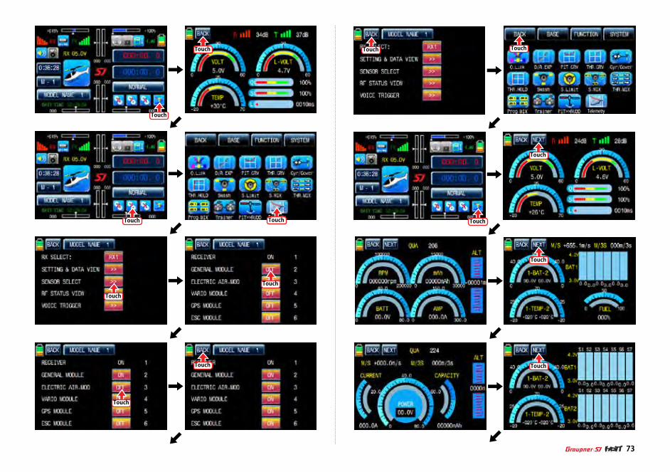
Telemetry
TelemetryTouch
Touch Touch
Touch
Touch
Touch
Touch
Touch Touch
Touch
Touch
Touch
Touch
Touch
73

Touch
Touch
Touch
Touch
Touch
Telemetry
Touch Touch
74
1. Q.LINK
This function is used to set Q.LINK and assign the corresponding switch to cope with the un-expected trouble situation. Since the adjusted value is activated by moving the switch and you can cope with the crisis with just one switch. It makes you operating the flight much easier. Q.LINK for airplane type consists of 8 types. (NORMAL, IDEL UP1, IDLE UP2, IDEL UP3, HOLD, Q.LINK6, Q.LINK7, Q.LINK8) Normal type is set as a default value.
In the transmitter main page, touch “Function” icon to call the Function page and touch “Q.LINK” icon to call Q.LINK setup page. Q.LINK list is displayed. “1.NORMAL” is the default value and it cannot be changed.
1-1 NEW
This function is used when you wish to create new Q.LINK. If you may want to set for new Q.LINK, touch the value in “Q.LINK” line to activate it in blue and touch “NEW” icon in the right to call “CTRL” and “DELAY” options. In “CTRL” setup, touch “NULL” icon to call “Select” message popup and move the switch or stick with your choice then the switch or stick is set to Q.LINK switch or stick. To set “DELAY” function, touch “0.0s” icon to activate in blue and set the delay time with “INC” and “DEC” buttons. DELAY indicates the time till Q.LINK start to work after Q.LINK is switched on
FUNCTION MENU (Airplane, Gilder)

Touch
Touch
Touch
Touch
Touch
Touch
Touch
Touch
Touch
Touch
Touch
75
1-2 NAM
It is used when to revise the name of “Q.LINK”. Touch the target value in “Q.LINK” to activate in blue. Now touch “NAM” icon to call NAM setup page. In the page, enter the desired name using the keypad. After that, touch “EN” icon then the revised name is displayed in “New Q.LINK Name”. Now, touch “BACK” icon on the left top left to call “Q.LINK” setup page and the revised name is stored at the corresponding Q.LINK.

Touch Touch
Touch
Touch
Touch Touch
Touch
76
1-3 CPY
CPY function is used to copy the preset Q.LINK setup data into another Q.LINK. Touch the desired entry in “Q.LINK” line to activate in blue. Touch “CPY” icon to call “COPY” message popup. Touch the entry in TARGET then all entry in TARGET are displayed in turn. Now, select the desired Q.LINK entry and touch “YES” icon then the preset data is saved into the selected Q.LINK entry and return to Q.LINK setup page.
1-4 DEL
It is used to delete the unused Q.LINK. Touch the entry in Q.LINIK line that you want to delete to activate in blue and touch “DEL” icon. Now, the selected Q.LINK entry is deleted in Q.LINK list
2. D/R, EXP
D/R function is used to adjust Servo travel amount that is connected to all channels including aileron, elevator and rudder channels. You can assign them to numerous switches and sticksEXP function is used to set D/R function to aileron, elevator and rudder channels and adjust the sensitivity of natural position of every channel. Positive Exponential reduces the control sensitivity of neutral position for more precise control and negative exponential increase the control sensitivity of neutral position D/R, EXP function can be operated with the assigned switch or connected to Q.LINK for purpose In the function page, touch “D/R, EXP” icon to call D/R, EXP setup page. Touch D/R or EXP icon to activate in blue and perform D/R or EXP programming setup with “INC” and “DEC”.
1-5 NEXT
If you touch “NEXT” icon, you may call the next page

Touch
Touch
Touch
Touch
Touch
Touch
77
Telemetry
Touch
Touch
Touch
After “D/R”, “EXP” setup, perform CTL setup. It is used to assign a switch to D/R, EXP function Touch “NULL” icon in CTL line to call “Select” message popup and move the switch that you want to use then that switch is set on/ off to switch and the switch direction setup page appears. You may select ON or OFF by touching icons. When the switch is moved to the direction of ON, the function is operated. Touch “Back” icon to return D/R, EXP setup page. When D/R, EXP switch is off, D/R, EX is returned to the default setup.If you want to use stick instead of switch for “D/R”, “EXP” function, Touch SW6 in CTL line to call “Select” message popup and move the stick with your choice then that stick is selected as on/ off stick and the stick direction setup page appears. In the direction setup page, move the stick to the position that you can comfortably reach, when the stick reach this position, D/R, EXP function is off. Touch “ENT” icon on the right bottom then the designated position is marked with the red or blue bar in the graph and the value of set position is displayed in POS. If you touch REVERSE in “DIR” line, all setup is reversed. To set “ON” or “OFF” at the both end of stick operation range, touch “SINGLE” icon to change to “DUAL” then D/R, EXP function is on or off at the both end of stick operation range. You may set ELEV and RUDD channel in the same way. We recommend to set 5~12 channels to Q.LINK since they don’t have on/off setup in D/R, EXP. When the setting is completed, touch “BACK” icon to return the function page.
Touch
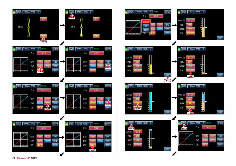
Touch
Touch
Touch
Touch
Touch
Touch
Touch
Touch
Touch
Touch Touch
Touch
Touch
78
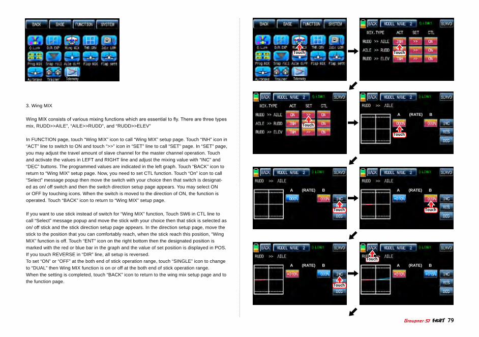
79
Telemetry
Touch Touch
Touch
Touch
Touch
Touch
Touch
Touch
A (RATE) B
A (RATE) B
A (RATE) B
A (RATE) B
A (RATE) B
Telemetry
3. Wing MIX
Wing MIX consists of various mixing functions which are essential to fly. There are three types mix, RUDD>>AILE”, “AILE>>RUDD”, and “RUDD>>ELEV”
In FUNCTION page, touch “Wing MIX” icon to call “Wing MIX” setup page. Touch “INH” icon in “ACT” line to switch to ON and touch “>>” icon in “SET” line to call “SET” page. In “SET” page, you may adjust the travel amount of slave channel for the master channel operation. Touch and activate the values in LEFT and RIGHT line and adjust the mixing value with “INC” and “DEC” buttons. The programmed values are indicated in the left graph. Touch “BACK” icon to return to “Wing MIX” setup page. Now, you need to set CTL function. Touch “On” icon to call “Select” message popup then move the switch with your choice then that switch is designat-ed as on/ off switch and then the switch direction setup page appears. You may select ON or OFF by touching icons. When the switch is moved to the direction of ON, the function is operated. Touch “BACK” icon to return to “Wing MIX” setup page.
If you want to use stick instead of switch for “Wing MIX” function, Touch SW6 in CTL line to call “Select” message popup and move the stick with your choice then that stick is selected as on/ off stick and the stick direction setup page appears. In the direction setup page, move the stick to the position that you can comfortably reach, when the stick reach this position, “Wing MIX” function is off. Touch “ENT” icon on the right bottom then the designated position is marked with the red or blue bar in the graph and the value of set position is displayed in POS. If you touch REVERSE in “DIR” line, all setup is reversed. To set “ON” or “OFF” at the both end of stick operation range, touch “SINGLE” icon to change to “DUAL” then Wing MIX function is on or off at the both end of stick operation range. When the setting is completed, touch “BACK” icon to return to the wing mix setup page and to the function page.

Touch
Touch
Touch
Touch
Touch
Touch
Touch
Touch
Touch
80
Telemetry
4. THR,CRV
This function adjusts the throttle operation curve in relation to the movement of the throttle stick for each conditionSince the throttle curve is closely related with Q.LINK setup, Q.LINK setup should precede THR.CRV setup.Call Q.LINK setup page and check Q.LINK setup is completed correctly and touch “BACK” icon to return FUNCTION page. (Refer to the manual on Q.LINK setup)
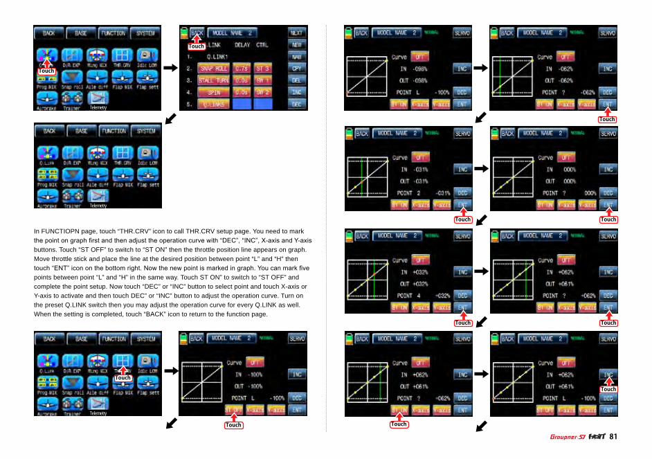
Touch
Touch
Touch
Touch
81
Telemetry
Telemetry
Telemetry
Touch
Touch
Touch
Touch
Touch
Touch
Touch
In FUNCTIOPN page, touch “THR.CRV” icon to call THR.CRV setup page. You need to mark the point on graph first and then adjust the operation curve with “DEC”, “INC”, X-axis and Y-axis buttons. Touch “ST OFF” to switch to “ST ON” then the throttle position line appears on graph. Move throttle stick and place the line at the desired position between point “L” and “H” then touch “ENT” icon on the bottom right. Now the new point is marked in graph. You can mark five points between point “L” and “H” in the same way. Touch ST ON” to switch to “ST OFF” and complete the point setup. Now touch “DEC” or “INC” button to select point and touch X-axis or Y-axis to activate and then touch DEC” or “INC” button to adjust the operation curve. Turn on the preset Q.LINK switch then you may adjust the operation curve for every Q.LINK as well. When the setting is completed, touch “BACK” icon to return to the function page.

Touch Touch
Touch
Touch
Touch
Touch
Touch
82
Telemetry
Telemetry
5. Idle LOW
It is used to lower the idle speed of the engine temporarily when airplane landsIn FUNCTIOPN page, touch “Idle LOW” icon to call “Idle LOW” setup page and touch and switch “INH” in ACT line to “ON” then Idle LOW function is activated. Touch “ON” in CTL line to call “Select” message popup then move the switch with your choice then that switch is des-ignated as on/ off switch and then the switch direction setup page appears. You may select ON or OFF by touching icons. When the switch is moved to the direction of ON, the function is operated. Touch “BACK” icon to return to Idle LOW setup page. Now, you need to set the op-eration value of Idle LOW. Touch and activate the value in SET line and set the desired value with INC and DEC buttons. Touch “BACK” icon to return to FUNCTION pageNOTICE: After setup Idle LOW, make sure to check the arrow direction of throttle channe

Touch
Touch
Touch
Touch
Touch
Touch
83
Telemetry
6. Prog.MIX
Prog.MIX function is used to mix the different channels for diverse purpose. We recommend you to use the same “On” switch with the one of Q.LINK. You may set the different program mix function for each Q.LINK condition. 8 MIXs are available. The mixing method introduced here is divided into 2 type, liner mixing type and curve mixing type. 1~5 MIXs are liner mixing type and 6~8 MIX is curve mixing type.
6-1. Liner mixing type
In FUNCTION page, touch “Prog.MIX” icon to call the prog.mix page. Touch “INH” icon in ACT line to switch to “ON” and touch “NONE” in MST line to call the mixing channel setup page. Touch and activate “NONE” icon and select the desired channel for the master by touching. Now, touch and activate the left “NONE” icon, it is for Slave channel, and select the desired channel for the slave by touching. Touch “BACK” icon to return to Prog.MIX setup page. Touch >> icon in SET line to call the program mixing setup page. Now, you need to set CTL function. - CTL setup with a switch
Touch “NULL” icon in CTL line to call “Select” message popup then move the switch with your choice then that switch is designated as on/ off switch and then the switch direction setup page appears. You may select ON or OFF by touching icons. When the switch is moved to the direction of ON, the function is operated. Touch “BACK” icon to return to Prog.MIX setup page.
- CTL setup with a stick
Touch “SW6” icon in CTL line to call “Select” message popup then move the stick with your choice then that stick is designated as on/ off stick and then the stick direction setup page appears. Move the stick to the position that you can comfortably reach, when the stick reach this position, Prog.MIX function is off.
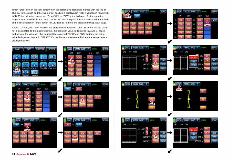
Touch
Touch
Touch
Touch
Touch
Touch
Touch Touch
Touch
Touch
Touch
Touch
ACT
A
CTL
B
ACT
A
CTL
B
ACT
A
CTL
B
ACT
A
CTL
B
84
Telemetry
Touch “ENT” icon on the right bottom then the designated position is marked with the red or blue bar in the graph and the value of set position is displayed in POS. If you touch REVERSE in “DIR” line, all setup is reversed. To set “ON” or “OFF” at the both end of stick operation range, touch “SINGLE” icon to switch to “DUAL” then Prog.MIX function is on or off at the both end of stick operation range. Touch “BACK” icon to return to the program mixing setup page.
After CTL setup, you need to adjust the program mix operation value. Since the throttle chan-nel is designated to the master channel, the operation value is displayed in A and B. Touch and activate the values in blue to adjust the value with “DEC” and “INC” buttons, the setup value is displayed in graph. OFFSET X/Y can be set the same method and the setup value is displayed as well.
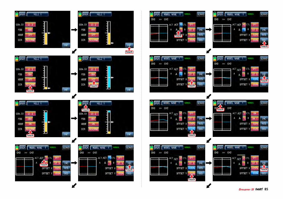
Touch
Touch
Touch
Touch
Touch
Touch
Touch
ACT
A
CTL
B
ACT
A
CTL
B
ACT
A
CTL
B
ACT
A
CTL
BTouch
Touch
85
Touch
Touch
Touch
Touch
Touch
Touch
ACT
A
CTL
B
ACT
A
CTL
B
ACT
A
CTL
B
ACT
A
CTL
B
ACT
A
CTL
B
1
1
1 1
1
1
ACT
A
CTL
B

86
Touch
Touch
Touch
Touch
Touch
Touch
Telemetry
6-2. Curve mixing type
In the prog.mix page, touch “NEXT” icon to call the next page and touch “INH” icon in the cross line of NO7 and ACT to switch to “ON”. Touch “NONE” in MST line to access the channel selection page and touch and activate “NONE” icon to select the desired channel of MST and SLV. Touch “BACK” icon to return to the prog.mix page. Touch “>>” icon to call the program mixing setup page. Now, you need to set CTL function.
- CTL setup with a switchTouch “ON” icon in CTL line to call “Select” message popup then move the switch with your choice then that switch is designated as on/ off switch and then the switch direction setup page appears. You may select ON or OFF by touching icons. When the switch is moved to the direction of ON, the function is operated. Touch “BACK” icon to return to the program mixing setup page.
- CTL setup with a stick Hoping that you would refer the explanation as explained above
Here, you need to set the operation value, “L” and “H” points are set by default and you need to mark 5 points between “L” and “H” on graph first and then adjust the operation curve with “DEC”, “INC”, X-axis and Y-axis buttons. Touch “ST OFF” icon to switch to “ST ON” then the blue line appears on graph. Move the designated switch or stick to place the line at the desired position then touch “ENT” icon on the bottom right. Now the new point is marked in graph. You may set five points in your favorable position.
Touch
Touch
ACT
A
CTL
B
ACT
A
CTL
B
Touch “PITT >> RUDD” icon in the function page to call PIT >> RUDD setup page. You need to mark the point on graph first and then adjust the operation curve with “DEC”, “INC”, X-axis and Y-axis buttons. Touch “ST OFF” icon to switch to “ST ON” then the pitch position line appears on graph. Move throttle stick and place the line at the desired position between point “L” and “H” then touch “ENT” icon on the bottom right. Now the new point is marked in graph. Touch ST ON” to switch to “ST OFF” and complete the point setup. Now touch “DEC” or “INC” button to select point and touch X-axis or Y-axis to activate and then touch DEC” or “INC” button to adjust the operation curve.

87
Touch
Touch
Touch
Touch
Touch
Touch
Touch
Touch
Touch
Touch
Touch Touch

Touch
Touch
Touch
Touch
Touch
Touch
Touch
Touch
88
Touch
Touch
Touch
Telemetry
Touch
Touch
7. Snap roll
It is used to select the switch and adjust the value of AILE, ELEV, RUDD channels for the snap roll function. Four snap roll directions can be set for your convenience.
In function page, touch “Snap roll” icon to call the snap roll setup page. Touch “INH” icon in ACT line to switch to ON. Touch and activate the value in AILE, ELEV and RUDD line to adjust the values with “INC” and “DEC” buttons. Touch “NULL” icon in CTL line to call “Select” message popup then move the switch with your choice then that switch is designated as on/ off switch and then the switch direction setup page appears. You may select ON or OFF by touching icons. When the switch is moved to the direction of ON, the function is operated. Touch “BACK” icon to return to Snap roll setup page and to FUNCTION page

Telemetry
Touch
Touch
TouchTouch
89
Telemetry
Touch
Touch
Touch Touch
Touch
Touch
8. Aile diff
This function decreases the amount an aileron moves down without affecting the amount the other aileron moves up. This can decrease adverse yaw (right or left movement of the aircraft nose) tendencies during roll maneuvers.
Touch “Aile diff” icon to call “Aile diff” setup page. The setup options are different for each wing type. In “Aile diff” setup page, touch and activate the values in “RATE A” and “RATE B” lines to adjust them with INC and DEC buttons. We recommend setting accurately over the flight. Now, touch “Servo” icon on the left top to call SERVO VIEW page. In this page, you may check the value for the aileron stick movement in a graph. Touch “BACK” icon to return to the aile diff setup page and the function page.

Telemetry
Touch
Touch
Touch
Touch
Touch
Touch Touch
90
Telemetry Telemetry
Touch Touch
9. Flap MIX
It consists of 4 mixing types, “FLAP”, ”AILE>>FLAP”, “ELEV>>FLAP”, and “FLAP>>ELEV”.
9-1. FLAP
This function is used to adjust the flap angle to increase or decrease airplane liftTo setup the flap function, you need to designate on/off control key such as switch, stick and volume. When you move the control key, the flap function is operated. Touch “CH SET” in BASE page to call “CH SET” setup page. Touch “NONE” icon in FLAP 1 line to pop up “Select” message. Move the control key with your choice then that control key is designated as on/ off key. Now, touch “SERVO” icon in the right top to call the servo view page. The default value, 30%, for the travel amount of servo is displayed in the graph and this function value can be adjusted. To adjust the function value, touch “Flap MIX” icon in the function page to call Flap Mix page and touch “>>” icon in SET line to call the flap setup page. Touch and activate the function value to adjust with INC and DEC buttons. Now, touch “SER-VO” icon again to call the servo view page then you may check the setup value in this page. After setup, touch “BACK” icon to return to Flap MIX page.

Telemetry
OFFSET
Touch
Touch
Touch
Touch
Touch
Touch
Touch
Touch
91
OFFSETOFFSET
OFFSET
OFFSETOFFSETTouch
TouchTouch
OFFSET
9-2. AILE >> FLAP
This mixing allows the entire trailing edge of the wing (aileron and flap) to operate as ailerons. When active, as aileron is applied the flaps also move so that the airplane rolls faster. In FLAP MIX page, touch “INH” icon in ACT line to switch to “ON” then AILE >>FLAP function is activated. Touch “ON” in CTL line to call the “Select” message popup and move the switch or stick or volume with your choice then that switch or stick or volume is designated as on/ off key and then the key direction setup page appears. You may select ON or OFF by touching icons. When the key is moved to the direction of ON, the function is operated. Touch “BACK” icon to return to FLAP MIX page. Touch “>>” icon in “SET” and “AILE >> FLAP” cross line to call “AILE >> FLAP” setup page. Touch and activate the values in blue and adjust them with INC and DEC buttons. When the setup is completed, touch SERVO icon on the top right to call SERVO page. You may check the setup value for “AILE >> FLAP”.

Touch Touch
Touch
Touch
Touch
Touch
Touch
Touch
Touch
Touch
TouchTouch
92

Touch Touch
Touch
Touch
Touch
93
Touch
Touch
Touch
Touch
Touch
9-3. ELEV >> FLAP
This mixing creates more lift of airplane, allowing a tighter turn. The entire trailing edge of the wing (aileron and flap) operates as flaps when elevator is applied. Touch INH icon in ACT line to switch to “ON” then ELEV >> FLAP is activated. Touch “ON” in CTL line to call the “Select” message popup and move the switch or stick or volume with your choice then that switch or stick or volume is designated as on/ off key and then the key direction setup page appears. You may select ON or OFF by touching icons. When the key is moved to the direction of ON, the function is operated. Touch “BACK” icon to return to FLAP MIX page. Touch “>>” icon in “SET” and “ELEV >> FLAP” cross line to call “ELEV >> FLAP” setup page. You may call “ AILE” and “FLAP” setup page with NEXT button in the top right. Touch and activate the val-ues in blue and adjust them with INC and DEC buttons. When the setup is completed, touch SERVO icon on the top right to call SERVO page. You may check the setup value for “ELEV >> FLAP”.

Touch
Touch
Touch
Touch
Touch
Touch
Touch
Touch Touch
Touch
Touch94
9-4. FLAP >> ELEV
This mixing prevents the change of the nose of airplane that occurs when FLAP is applied by operating elevator In FLAP MIX page, touch “INH” icon in ACT line to switch to “ON” then FLAP >> ELEV function is activated. Touch “ON” in CTL line to call the “Select” message pop-up and move the switch or stick or volume with your choice then that switch or stick or volume is designated as on/ off key and then the key direction setup page appears. You may select ON or OFF by touching icons. When the key is moved to the direction of ON, the function is operated. Touch “BACK” icon to return to FLAP MIX page. Touch “>>” icon in “SET” and “FLAP >> ELEV” cross line to call “FLAP >> ELEV” setup page. Touch and activate the values in blue and adjust them with INC and DEC buttons. When the setup is completed, touch SERVO icon on the top right to call SERVO page. You may check the setup value for “FLAP >> ELEV”. The preset set “FLAP” and the set “FLAP >> ELEV” are activated at the same time when SW5 which was set in “FLAP >> ELEV” is set to “ON”.

Touch
Touch
Touch
Touch
Touch
Touch
Touch
Touch
95
Touch
Flap mix Functions can be adjusted for each Q.LINK condition.
10. Flap sett (Airplane, Gilder)
This mixing allows that the aileron, flap and elevator setups are applied at the same time by operating a switch. Touch “Flap sett” icon to access to the “Flap sett” setup page. The first page is AILE setup and you may access to FLAP and ELEV setup page by touching “NEXT” icon in the top right. Touch “INH” icon in ACT line to switch to “ON” and touch “ON” in CTL line to call the “Select” message popup. Move the switch or stick or volume with your choice then that switch or stick or volume is designated as on/ off key and then the key direction setup page appears. You may select ON or OFF by touching icons. When the key is moved to the direction of ON, the function is operated. Touch “BACK” icon to the previous page then touch and activate the values in blue and adjust them with “INC” and “DEC” buttons. After performing the program-ming setup of AILE and FLAP and ELEV in turn, touch SERVO icon on the top right to call SERVO page. You may check the setup value for Flap sett. When Tx and Ctl are set to DV1, DV2, DV3, DV4, SL1, and SL2 in advance, the setup values are applied by operating “DV” or “SL” while flying

Touch
Touch
Touch
Touch
Touch
Touch
Touch
Touch
Touch
Touch
Touch
Touch
Touch
96
Telemetry

Touch
Touch
Touch
97
Telemetry
Touch
Touch
Touch
Touch
Touch
Touch
Telemetry
11. Airbrake (Airplane)
This mixing is used when the airplane is need to land or descent vertically. Airbrake can be set by AILE, FLAP and ELEV.
Touch “Airbrake” icon in the function setup page to call the airbrake setup page. The first page is AILE setup and you may access to FLAP, ELEV and AIRBRAKE DELAY setup page by
touching “NEXT” icon in the top right. Touch “INH” icon in ACT line to switch to “ON” and touch “ON” in CTL line to call the “Select” message popup. Move the switch or stick or volume with your choice then that switch or stick or volume is designated as on/ off key and then the key direction setup page appears. You may select ON or OFF by touching icons. When the key is moved to the direction of ON, the function is operated. Touch “BACK” icon to the previous page then touch and activate the values in blue and adjust them with “INC” and “DEC” but-tons. After the programming setup of FLAP, ELEV and AIRBRAKE DELAY in turn, touch SER-VO icon on the top right to call SERVO page. You may check the setup value for Airbrake.

Touch
Touch
Touch
Touch
Touch
Touch
Touch
Touch
Touch
Touch
Touch
Touch
98

Touch
Touch
Touch
99
Telemetry Telemetry
Touch
Touch
Touch
Touch
Touch
12. Butterfly (Glider)
It is used in glider type only. This function allows powerful brake operation by simultaneously raising the left and right ailerons and lowering the flaps. Butterfly produces an extremely efficient landing configuration by flying at a slower speed. CAUTION: We recommend that you do several tests on high altitude to make the best use of this function.
For the setup of butterfly function, touch “Butterfly” icon to access to the Butterfly setup page. Touch “INH” icon to switch to “ON” to call the “Select” message popup and move the switch or stick or volume with your choice then that switch or stick or volume is designated as on/ off key and then the key direction setup page appears. You may select ON or OFF by touching icons. When the key is moved to the direction of ON, the function is operated. Touch “BACK” icon to return to the Butterfly setup page. The setup pages of AILE, FLAP, ELEV and BUT-TERFLY OFF appear by touching “NEXT” button. AILE, FLAP values are activated in blue by touching and adjusted with INC and DEC buttons. ELEV can be set with curve in the graph. You need to mark the point on graph first and then adjust the operation curve with “DEC”, “INC”, X-axis and Y-axis buttons. Touch “ST OFF” to change to “ST ON” then the throttle position line appears on graph. Move throttle stick and place the line at the desired position between point “L” and “H” then touch “ENT” icon on the bottom right. Now the new point is marked in graph. You can mark five points between point “L” and “H” in the same way. Touch ST ON” to change to “ST OFF” and complete the point setup. Now touch “DEC” or “INC” but-ton to select point and touch X-axis or Y-axis to activate and then touch DEC” or “INC” button to adjust the operation curve. If you touch OFF icon in Curve line, it is changed to ON and the operation curve is smoother. Now touch “NEXT” icon to call “BUTTERFLY OFF” setup page. This function is used to set whether it is switched off. Move and hold the throttle stick to the desired position for the function off and touch the value then the stick position is decided and the assigned value is displayed. The butterfly function is operated under the assigned value and it is not operated over the assigned value. When the setting for butterfly is completed, touch “S” icon on the top right to access to Servo page. In Servo page, you may check the setup value of AILE, FLAP, and ELEV.

Touch
Touch Touch
Touch
Touch
Touch
Touch
Touch Touch
Touch
Touch
Touch
100
1. ST mode
The Stick model can be selected from 1 to 4. “Mode 1” is widely used in ASIA and Mode 2 is widely used in North America and Europe and also mode 3, 4 are available to use.In the initial page, touch “SYSTEM” icon to call SYSTEM setup page and touch “ST mode” icon to call ST mode setup page. In ST mode setup page, ST mode is selectable from “1” to “4” whenever “ST mode number” is touched and the indications are displayed for each ST mode. When the stick setup is completed, touch “BACK” icon to call the SYSTEM menu page
SYSTEM (Helicopter, Airplane, Gilder)

Etc.Set
Etc.Set
Touch
Touch Touch
Touch
Touch
Touch
101
Touch Touch
Touch
Touch
Touch
Touch
Etc.Set
2. Warning
The Warnings function programs an alarm to sound to be made if specific switches or stick positions are in an unsafe position when the transmitter is powered on. You can program 5 warnings such as “Throttle Hold”, “Throttle Cut”, “Thro Position”, “Quick Link”, and “Power Off time”. “On” is basically set in only “Thro Position” and “Off” is basically set in the others. Touch “ON/OFF” icons to switch to “OFF/ON”. After the setup is completed, touch “BACK” icon on the top left to return to “SYSTEM” menu page.

Etc.SetTouch Touch
Touch
Touch
102
Etc.Set
Etc.Set
ON
03
ON
03
ON
03
ON OFFPower on Melody
Speaker Volume
Power on Melody
Speaker Volume
Power on Melody
Speaker Volume
Power on Melody
Speaker Volume
Power on Melody
Speaker Volume
Power on Melody
Speaker Volume
Power on Melody
Speaker Volume
4.5V
4.5V
4.5V
4.5V
4.5V
03
03
05
05
03
Touch
Touch
Touch
Touch
Touch
Touch
ON
03
ON
03Touch
Power on Melody
Speaker Volume
Power on Melody
Speaker Volume
Power on Melody
Speaker Volume
OFF
OFF
OFF
3. Etc. set It is used to select the battery type and set battery warning voltage, Power on melody and Speaker volume. Touch “Etc. set” icon to call Etc. set page and touch and activate the value in blue. After that, choose the desired battery type, warning time, Power on Melody and Speaker volume with INC and DEC icons. If the setup is completed, touch “BACK” icon to return to the System menu page.

Etc.SetTouch Touch
Touch
Touch
Touch
DEFAULTLogo color
Glaring sun
DEFAULTLogo color
Glaring sun
DEFAULTLogo color
Glaring sun
DEFAULTLogo color
Glaring sun
DEFAULTLogo color
Glaring sun
DEFAULTLogo color
Glaring sun
DEFAULTLogo color
Glaring sun
Touch
Touch
Touch
Logo color Logo color
Glaring sun Glaring sun
Touch
Touch
DEFAULT BLUE
3 3
103
BLUELogo color
Glaring sun
BLUELogo color
Glaring sun
Touch
3 3
ON
Touch
4. Display
It is used to adjust TFT LCD’s contrast, back light off time, the sensitivity of Touch sense, Logo color and Glaring sun. Touch “Display” icon in the system menu page to access to the display setup page. In this page, touch and activate the value in blue and set the relevant val-ue to each category with the INC and DEC icons. After the setup is completed, touch “BACK” icon to return to the System menu page. NOTICE: In Glaring sun category, we recommend to switch the value to “ON”. It enables the more clear display in the sun
Etc.Set

104
Touch
Touch
Touch
Touch
Touch
Touch
Touch
Etc.Set
Touch
Etc.Set
5. Stick Cali
It is used to calibrate the stick’s neutral positionTouch “Stick Cali” icon in the system menu page to call “Stick Cali’ page. The right stick and the left stick of transmitter are calibrated in turn and the stick position is indicated on VERTI, HORIZ with percentage
- Center: When the dot is centered on the graph, move and hold the stick at the desired neu-tral position and touch “SET” icon then the stick’s neutral position is saved.
- Full down, Full left: When the dot is at the corner of the top left on the graph, move and hold the stick at the desired end position of the top left and touch “SET” icon then the stick’s Full down/Full left position is saved.
- Full up, Full right: When the dot is at the corner of the bottom right on the graph, move and hold the stick at the desired end position of the bottom right and touch “SET” icon then the stick’s Full up/Full right position is saved.After Full up and Full right setup, ”Stick Calibration complete!” message is popped up. Now, touch “Yes” icon to complete the Stick Calibration setup. Touch the “Back” icon to return to SYSTEM menu page.

Etc.Set
105
Touch
Touch
Touch
Touch
6. MP3
You may listen to the music by storing music files on SD card. You can enjoy music while flying or practicing. To make use of MP3 function, touch “MP3” icon to call the MP3 setup page. You may select folder with <A, A> icons and select the song with “<<, >>” icons. Also you can control a volume with “–“ and ”+” icons. You may repeat the music (all song, one song selectable) and stop the repeat with a repeat icon and play or pause the music with the start and pause icon. When “BACK” icon is touched, you may return to “SYSTEM” menu page.
TouchTouch
Touch
Etc.Set
Touch Touch
• FIRMWARE UPDATE
For more information on the latest firmware and the related software, please refer to the
download menu on our website www.openhobby.com, www.graupner-sj.com
NOTICE: The optional USB adapter is needed to update.

106
Declaration of Conformity
(in accordance with ISO/IEC 17050-1)
- Product(s): Graupner/SJ mz-24 Transmitter
Item Number(s):
Equipment class: 2
The objects of declaration described above are in conformity with the requirements of the
specifications listed below, following the provisions of the European R&TTE directive 1999/5/
EC:
EN 62479:2010 EN 60950-1:2006/A11:2009/A1:2010/A12:2011 EN 301 489-1 V1.9.2 EN 301-489-17 V2.2.1 EN 300 328 V1.7.1
FCC Information
- Graupner /SJ mz-24 Transmitter
Contains FCC ID: SNL-36204410 FCC 47 CFR PART 15C FCC 47 CFR PART 15B
FCC Statement
1. This device complies with Part 15 of the FCC Rules. Operation is subject to the following
two conditions:
(1) This device may not cause harmful interference.
(2) This device must accept any interference received, including interference that may cause
undesired operation.
2. Changes or modifications not expressly approved by the party responsible for compliance
could void the user‘s authority to operate the equipment.
• FCC radiation exposure statement
This equipment complies with FCC radiation exposure limits set forth for an uncontrolled
environment. This equipment should be installed and operated with minimum distance of 20
cm between the radiator and your body.
• KC Information
- Graupner /SJ mz-24 Transmitter
- KCC인증번호: KCC-CRM-sjr-16005200, KCC-CRM-sjr-36204410
- 방송통신위원회고시 제2013-01호 “무선설비규칙”
- 방송통신위원회고시 제2012-102호 “신고하지 아니하고 개설할 수 있는 무선기기”
KN 301 489-1:2009 KN 301 489-17:2009 KN 61000-4-2:2008 KN 61000-4-3:2011
• NOTE
This equipment has been tested and found to comply with the limits for a Class B digital de-
vice, pursuant to Part 15 of the FCC Rules. These limits are designed to provide reasonable
protection against harmful interference in a residential installation. This equipment generates
uses and can radiate radio frequency energy and, if not installed and used in accordance with
the instructions, may cause harmful interference to radio communications. However, there
is no guarantee that interference will not occur in a particular installation. If this equipment
does cause harmful interference to radio or television reception, which can be determined by
turning the equipment off and on, the user is encouraged to try to correct the interference by
one or more of the following measures:
• Reorient or relocate the receiving antenna.
• Increase the separation between the equipment and receiver.
• Connect the equipment into an outlet on a circuit different from that to which the receiver is
connected.
• Consult the dealer or an experienced radio/TV technician for help.
• SAFETY APPROVAL

107
• Caution
• This equipment’s aerial must be at least 20 cm from any person when the system is in use. We
therefore do not recommend using the equipment at a closer range than 20cm.
• Ensure that no other transmitter is closer than 20cm from your equipment, in order to avoid
adverse effects on the system’s electrical characteristics and radiation pattern.
• The radio control system should not be operated until the Country setting has been set correctly
at the transmitter. This is essential in order to fulfill the requirements of various directives -
FCC, ETSI, CE, KC and etc. Please refer to the instructions for your particular transmitter and
receiver for details of this procedure.
• Check all working systems and carry out at least one full range check on the ground before
every flight, in order to show up any errors in the system and the models programming.
• Never make any changes to the programming of the transmitter or receiver whilst operating a
model.
• ENVIRONNEMENTAL PROTECTION NOTES
This product must not be disposed of with other waste. Instead,
it is the user’s responsibility to their waste equipment by handing it over to
a designated collection point for the recycling of waste electrical and
electronic equipment. The separate collection and recycling of
your waste equipment at the time of disposal will help to conserve natural resources and ensure
that it is recycled in a manner that protects human health and the environment. For more infor-
mation about where you can drop off your waste equipment for recycling, please contact your
local city office, your household waste disposal service or where you purchased the produce

No. S1006