Operating information for TROP - P and PW type feed pumps
2
Operating information for TROP - P and PW type feed pumps All P and PW type pumps are subject to the same operating principles. The 'P' type (three-phase current) may be connected to the power net by an electric installer only. The specified phase sequence must be observed by all means. A specialist has suitable measuring instruments and know-how to connect the pump motor with the correct phase- sequence. A protective motor switch with appropriate capacity for the installed motor is definitely required.Prior to the initial operation which must be effected without water the pump's head must be pulled off to the front by loosening and removing the four cap nuts first. The pump's impeller is now visible and the direction of rotation can be determined. For this purpose the motor may be actuated briefly only, i.e. for 5 secs. at most. Longer periods of dry running will damage the pump's seal! Warning: DO NOT touch the impeller when actuating the pump! Burned seals and burned stators (motor winding) by principle are excluded from any guaranty! The 'PW' type pumps by principle have been equipped with a thermofuse which interrupts the power supply in case of the motor overheating. Should this incidence ever happen the reason for this overheating of the motor shall be determined as soon as the fuse has been replaced! The pump's head may be turned by 45 degrees for all pumps, i.e. the pump's head may be pulled off to the front after the cap nuts have been removed and subsequently be reinstalled with the pump's outlet in another position. IMPORTANT: The cap nuts may be tightened slightly only to the point where the gap between the housing parts has been closed! Overtightening of the nuts will destroy the pump's head over a period of time which consequently will be distorted no longer assuring a sealing between the two halves of the head. Every motor requires air for cooling. Never place or install the pump into housings without ventilation! Place pump always horizontally on its footing, never operate in a slanted position! Place the pump in a location where it will be protected against dripping water! DO NOT connect the pump to stiff piping. Running noises may be transferred to the walls. Install a compression-proof tube made of fabric having a length of about 20cm between the pump and the piping (is possible up to type P20 only!). Remember to install a suction basket that should be selected of a dimension to prevent any passage of foreign objects above 3mm! Never try to manipulate the pumps. They have already been laid out for maximum output in their specific class! Exchanging of impellers and pump heads is not permitted and releases the manufacturer from any guarantee and liability! The air inlet at the back shall not be obstructed. Care should be taken to provide always 5cm clearance at least to any wall or similar object. Whenever a pump is removed from the supply lines the following instructions shall be observed: rinse the pump's head several times with tab water, remove the pump's head as instructed, turn the impeller counter- clockwise to remove it from the motor shaft. For this purpose hold the motor shaft in position using a 5mm screw driver to be pushed through one of the ventilator cowl's ventiducts. Warning! Take care not to damage the seal. DO NOT place the impeller on the seal. Even very small damages may cause a leakage! Rinse all pump components under running water. Use water with vinegar to remove possible furring on the seal, no mechanical cleaning! Subsequently the pump components may be reassembled in dry condition. The pump can now be stored until further use. After a storage period of more than 6 months there is a possibility of the bearings emitting loud noises after the renewed initial operation. This is due to the gumming of the bearing lubricant. In this case the pump should be returned for repair. Without hesitation the pumps described in these presents may be throttled on the delivery side, e.g. using ball valves. This will bring down the power consumption. Throttling of the flow by e.g. 20% will result in power savings of about 10%. A closure of more than 80%, however, must definitely be avoided. In cases where pumps of a greater pipe diameter than the pump's outlet are utilised this pipe must be reduced to the original dimension at the end! In case of doubt: measure the current input and compare to the markings on the motor type plate! Maximum operating temperature: 65 degrees C. Maintenance The pumps require no maintenance in the field. Service life depending on ambient humidity is about 35-50,000 hours. Subsequently the ball bearings need to be replaced where required. We strongly recommend to return the pumps to the manufacturer for any repair or overhaul. The accuracy of the repair can be guaranteed under this condition only. Innovations to the extend of being technically feasible will automatically be included in the overhaul work. Overhaul or repair appointments can be made within short delays! We reserve the right to technical modifications! Important!
Transcript of Operating information for TROP - P and PW type feed pumps
Operating information for TROP - P and PW type feed pumps
All P and PW type pumps are subject to the same operating principles. The 'P' type (three-phase current) may beconnected to the power net by an electric installer only. The specified phase sequence must be observed by all means.A specialist has suitable measuring instruments and know-how to connect the pump motor with the correct phase-sequence. A protective motor switch with appropriate capacity for the installed motor is definitely required.Prior to theinitial operation which must be effected without water the pump's head must be pulled off to the front by loosening andremoving the four cap nuts first. The pump's impeller is now visible and the direction of rotation can be determined. Forthis purpose the motor may be actuated briefly only, i.e. for 5 secs. at most. Longer periods of dry running will damagethe pump's seal! Warning: DO NOT touch the impeller when actuating the pump!
Burned seals and burned stators (motor winding) by principle are excluded from any guaranty!
The 'PW' type pumps by principle have been equipped with a thermofuse which interrupts the power supply in case ofthe motor overheating. Should this incidence ever happen the reason for this overheating of the motor shall bedetermined as soon as the fuse has been replaced!
The pump's head may be turned by 45 degrees for all pumps, i.e. the pump's head may be pulled off to the front after thecap nuts have been removed and subsequently be reinstalled with the pump's outlet in another position. IMPORTANT:The cap nuts may be tightened slightly only to the point where the gap between the housing parts has been closed!Overtightening of the nuts will destroy the pump's head over a period of time which consequently will be distorted nolonger assuring a sealing between the two halves of the head.Every motor requires air for cooling. Never place or install the pump into housings without ventilation! Place pumpalways horizontally on its footing, never operate in a slanted position! Place the pump in a location where it will beprotected against dripping water!DO NOT connect the pump to stiff piping. Running noises may be transferred to the walls. Install a compression-prooftube made of fabric having a length of about 20cm between the pump and the piping (is possible up to type P20 only!).Remember to install a suction basket that should be selected of a dimension to prevent any passage of foreign objectsabove 3mm!Never try to manipulate the pumps. They have already been laid out for maximum output in their specific class!Exchanging of impellers and pump heads is not permitted and releases the manufacturer from any guarantee andliability!The air inlet at the back shall not be obstructed. Care should be taken to provide always 5cm clearance at least to anywall or similar object.
Whenever a pump is removed from the supply lines the following instructions shall be observed:rinse the pump's head several times with tab water, remove the pump's head as instructed, turn the impeller counter-clockwise to remove it from the motor shaft. For this purpose hold the motor shaft in position using a 5mm screw driverto be pushed through one of the ventilator cowl's ventiducts. Warning! Take care not to damage the seal. DO NOT placethe impeller on the seal. Even very small damages may cause a leakage!Rinse all pump components under running water. Use water with vinegar to remove possible furring on the seal, nomechanical cleaning! Subsequently the pump components may be reassembled in dry condition. The pump can now bestored until further use. After a storage period of more than 6 months there is a possibility of the bearings emitting loudnoises after the renewed initial operation. This is due to the gumming of the bearing lubricant. In this case the pumpshould be returned for repair.
Without hesitation the pumps described in these presents may be throttled on the delivery side, e.g. using ball valves.This will bring down the power consumption. Throttling of the flow by e.g. 20% will result in power savings of about 10%.A closure of more than 80%, however, must definitely be avoided.
In cases where pumps of a greater pipe diameter than the pump's outlet are utilised this pipe must be reduced to theoriginal dimension at the end! In case of doubt: measure the current input and compare to the markings on the motortype plate! Maximum operating temperature: 65 degrees C.
MaintenanceThe pumps require no maintenance in the field. Service life depending on ambient humidity is about 35-50,000 hours.Subsequently the ball bearings need to be replaced where required. We strongly recommend to return the pumps to themanufacturer for any repair or overhaul. The accuracy of the repair can be guaranteed under this condition only.Innovations to the extend of being technically feasible will automatically be included in the overhaul work. Overhaul orrepair appointments can be made within short delays!
We reserve the right to technical modifications!
Important!

Short operating notes for TROP feed pumps, type P and PW
All pumps of the type P or PW are subject to the identical operating conditions.
A motor- residual current operated circuit breaker is to be fit in correct dimensioning.
Pumps type PW are equipped with a thermo fuse, which one while overloading the motor may cut offOnly tighten the four screws on the pump head easilyThe motor needs cooling, therefore not do the pumps into unventi lated small boxes.Only set up level the pump to the feet, do never assemble into side layer!Please, do the pump at a dry place, take care before dropping water!D o n o t c o n n e c t t h e p u m p s d i r e c t l y t o i n f l e x i b l e t u b e s y s t e m s , r u n n i n g n o i s e s c a n b etransferred.Assemble pressureproof woven tube between pump and tube-Sytems.Set a pump strainerat the entry of the pump, maximal hole item: 3mm!
Do not place too densely the motor to walls, it needs air supply!!
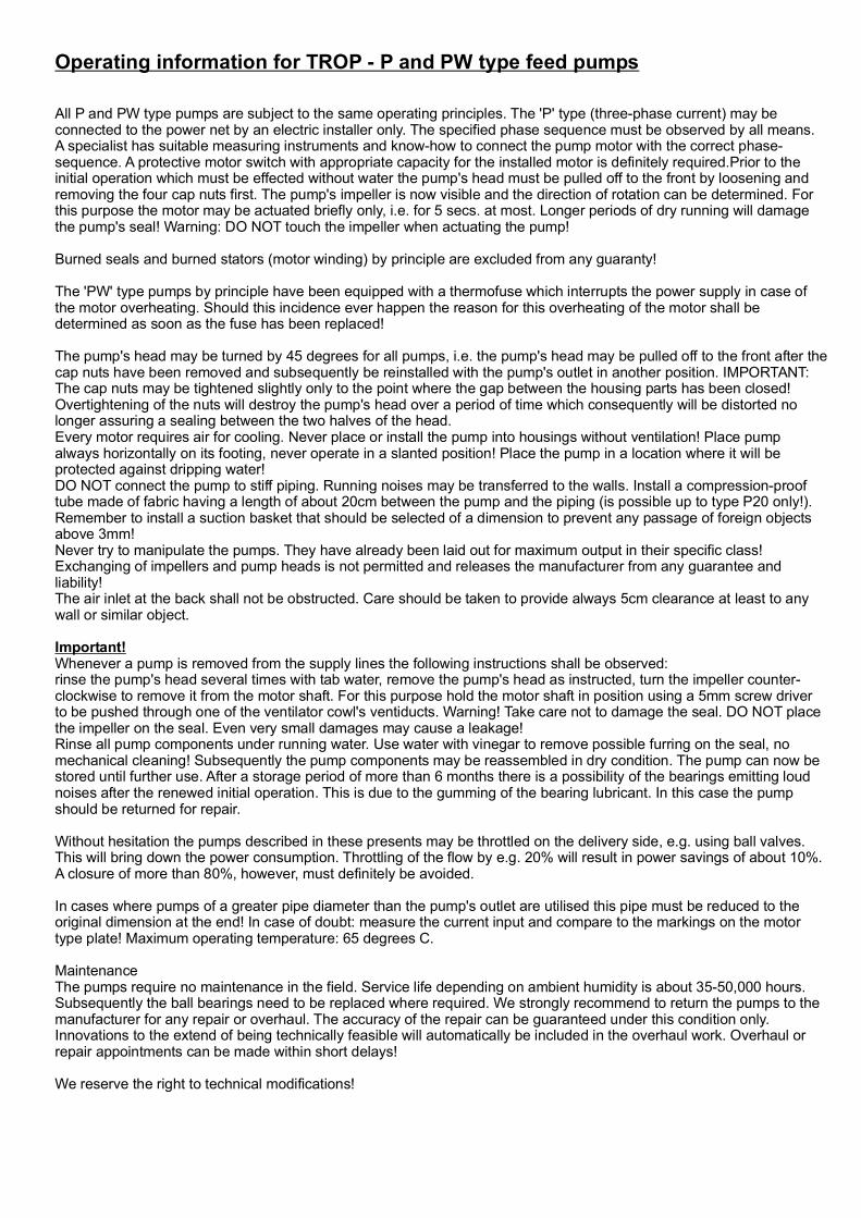
1) Remove four nuts
2) Remove pump head
3) Unscrew impeller anticlockwise, f
4) Clean all units in vinegar water, caution, !
5) Clean motor and blower cap & gear.
THE FIRST INITIATION OF THREE-PHASE PUMPS:
To dismantle pump head:
Set the correct direction of the rotating field during the first init iation of the three-phase pumps.
Burned seals or motor coils are excluded by Assurance!
If the pump is taken out of operation, the pump casing with water is to be rinse.
References to the pump- service
do not damage the seal
The first initiation is to be passed through without water!The pump head must be dismantled, around the direction of the rotating field the motor to con-trol. Let the motor only run short time. Caution! Do not osculate the impeller at current motor!
Please, considerthe rated current information on the motor type designation plate
(sucking side)
The pumps can be choked compression sided (outlet) e.g. with spherical valves, the power consump-tion decreases correspondingly.
irm the motorshaft at the back at the blower gear held.
Nuts
Pump head
Blower gearBlower cap