
Utilization of GPS Based Technology in Row Crop Research and ...

OPERATING AND PARTS MANUAL600 & 800 ROW CROP MODELS
www.DaltonAg.com602 E. VAN BUREN LENOX, IOWA 50851 800.342.7498
Mobility 800 Row Crop Mobility 600 Row Crop
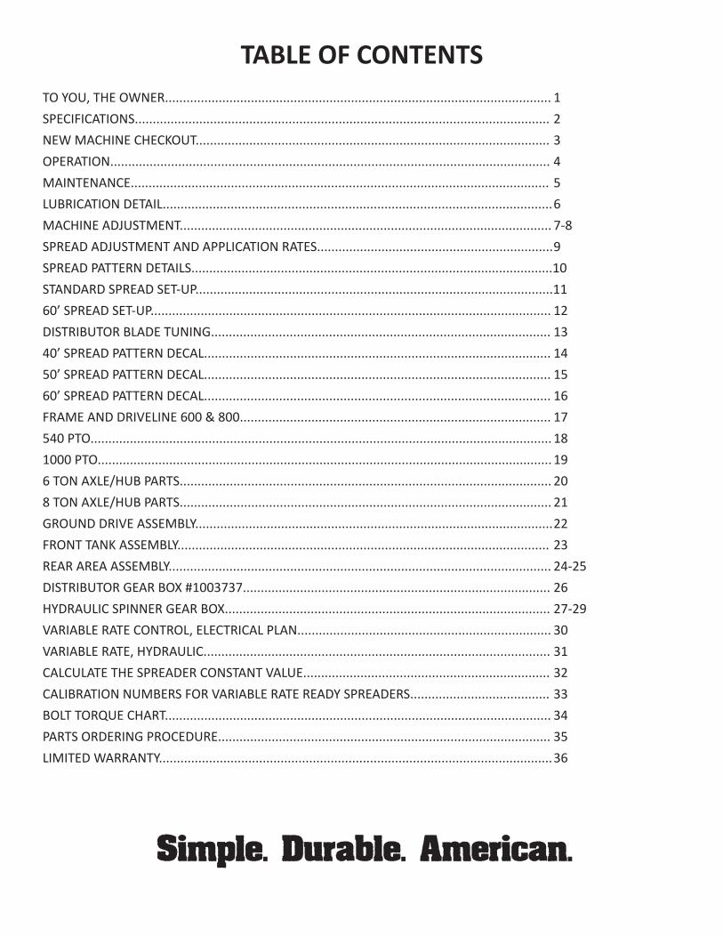
TABLE OF CONTENTSTO YOU, THE OWNER............................................................................................................ 1SPECIFICATIONS.................................................................................................................... 2NEW MACHINE CHECKOUT................................................................................................... 3OPERATION........................................................................................................................... 4MAINTENANCE..................................................................................................................... 5LUBRICATION DETAIL............................................................................................................. 6MACHINE ADJUSTMENT........................................................................................................ 7-8SPREAD ADJUSTMENT AND APPLICATION RATES.................................................................. 9SPREAD PATTERN DETAILS.....................................................................................................10STANDARD SPREAD SET-UP....................................................................................................1160’ SPREAD SET-UP................................................................................................................ 12DISTRIBUTOR BLADE TUNING............................................................................................... 1340’ SPREAD PATTERN DECAL................................................................................................. 1450’ SPREAD PATTERN DECAL................................................................................................. 1560’ SPREAD PATTERN DECAL................................................................................................. 16FRAME AND DRIVELINE 600 & 800....................................................................................... 17540 PTO................................................................................................................................. 181000 PTO............................................................................................................................... 196 TON AXLE/HUB PARTS........................................................................................................ 208 TON AXLE/HUB PARTS........................................................................................................ 21GROUND DRIVE ASSEMBLY.................................................................................................... 22FRONT TANK ASSEMBLY........................................................................................................ 23REAR AREA ASSEMBLY........................................................................................................... 24-25DISTRIBUTOR GEAR BOX #1003737...................................................................................... 26HYDRAULIC SPINNER GEAR BOX........................................................................................... 27-29VARIABLE RATE CONTROL, ELECTRICAL PLAN....................................................................... 30VARIABLE RATE, HYDRAULIC................................................................................................. 31CALCULATE THE SPREADER CONSTANT VALUE..................................................................... 32CALIBRATION NUMBERS FOR VARIABLE RATE READY SPREADERS....................................... 33BOLT TORQUE CHART............................................................................................................ 34PARTS ORDERING PROCEDURE............................................................................................. 35LIMITED WARRANTY.............................................................................................................. 36
Simple. Durable. American.

1
TO YOU, THE OWNER
Your Mobility Spreader is the most modern, up-to-date, versatile, machine available for broadcast application of bulk fertilizer and other granular materials. The machine is the result of many years of experience, research, development and testing of equipment for broadcast application. It is soundly engineered and carefully built to rigid specifications. It is of rugged and simple construction, with a minimum of moving parts.
However, to obtain maximum performance from your spreader, it is necessary to follow the instructions and safety suggestions in this manual. Each section has been carefully prepared for the purpose of providing needed and valuable information to the owner and operator. Each operator of this unit should be familiar with the contents of this manual. Keep it in a safe and convenient location. THERE ARE MANY SAFETY SUGGESTIONS (CAUTION AREAS) PRINTED THROUGHOUT THIS MANUAL. CAREFULLY READ THEM ALL BEFORE OPERATING THIS UNIT.
DESIGN IMPROVEMENTS
Dalton Ag Products follows a policy of continuous products improvement. We therefore reserve the right to make design improvements, and changes in specifications and prices, without incurring obligations to make revisions or additions to equipment previously sold.
1
12
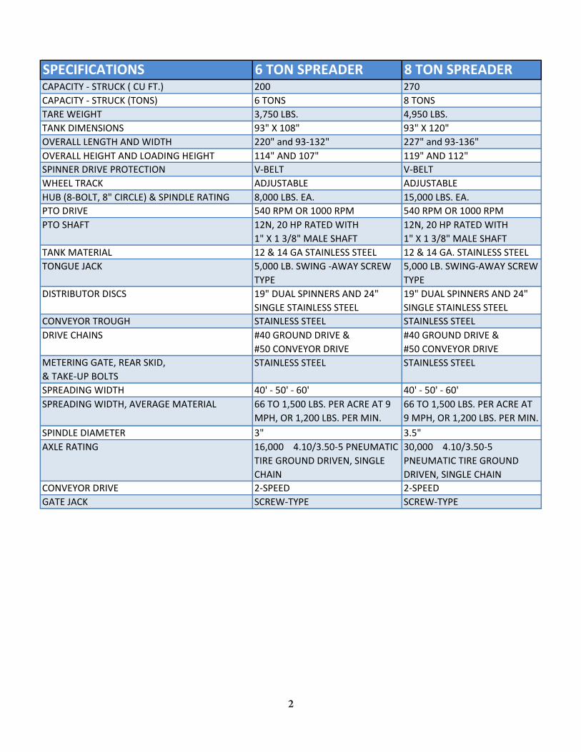
SPECIFICATIONS 6 TON SPREADER 8 TON SPREADERCAPACITY - STRUCK ( CU FT.) 200 270CAPACITY - STRUCK (TONS) 6 TONS 8 TONSTARE WEIGHT 3,750 LBS. 4,950 LBS.TANK DIMENSIONS 93" X 108" 93" X 120"OVERALL LENGTH AND WIDTH 220" and 93-132" 227" and 93-136"OVERALL HEIGHT AND LOADING HEIGHT 114" AND 107" 119" AND 112"SPINNER DRIVE PROTECTION V-BELT V-BELTWHEEL TRACK ADJUSTABLE ADJUSTABLEHUB (8-BOLT, 8" CIRCLE) & SPINDLE RATING 8,000 LBS. EA. 15,000 LBS. EA.PTO DRIVE 540 RPM OR 1000 RPM 540 RPM OR 1000 RPMPTO SHAFT 12N, 20 HP RATED WITH
1" X 1 3/8" MALE SHAFT12N, 20 HP RATED WITH 1" X 1 3/8" MALE SHAFT
TANK MATERIAL 12 & 14 GA STAINLESS STEEL 12 & 14 GA. STAINLESS STEELTONGUE JACK 5,000 LB. SWING -AWAY SCREW
TYPE5,000 LB. SWING-AWAY SCREW TYPE
DISTRIBUTOR DISCS 19" DUAL SPINNERS AND 24" SINGLE STAINLESS STEEL
19" DUAL SPINNERS AND 24" SINGLE STAINLESS STEEL
CONVEYOR TROUGH STAINLESS STEEL STAINLESS STEELDRIVE CHAINS #40 GROUND DRIVE &
#50 CONVEYOR DRIVE#40 GROUND DRIVE & #50 CONVEYOR DRIVE
METERING GATE, REAR SKID, & TAKE-UP BOLTS
STAINLESS STEEL STAINLESS STEEL
SPREADING WIDTH 40' - 50' - 60' 40' - 50' - 60'SPREADING WIDTH, AVERAGE MATERIAL 66 TO 1,500 LBS. PER ACRE AT 9
MPH, OR 1,200 LBS. PER MIN.66 TO 1,500 LBS. PER ACRE AT 9 MPH, OR 1,200 LBS. PER MIN.
SPINDLE DIAMETER 3" 3.5"AXLE RATING 16,000 4.10/3.50-5 PNEUMATIC
TIRE GROUND DRIVEN, SINGLE CHAIN
30,000 4.10/3.50-5 PNEUMATIC TIRE GROUND DRIVEN, SINGLE CHAIN
CONVEYOR DRIVE 2-SPEED 2-SPEEDGATE JACK SCREW-TYPE SCREW-TYPE

NEW MACHINE CHECKOUTBefore attempting to use or operate the spreader it is important to be thoroughly familiarized with the con-tents of this manual. Then the machine should be checked using the following check list:
1. Ground drive tire inflated to 22 PSI. Tires inflated to manufacturing specifications.
2. All bearings lubricated and tightly mounted with collars securely locked. (See lubrication schedule page 5.)
3. Conveyor chains, drive chain & ground drive chain adjusted to correct tension. Conveyor chain should clear frame members by ½ - ¾.
4. Sprockets tightened & in proper alignment.
5. Inspect entire machine for loose bolts, especially in the spinner assembly and drive line area.
6. Distributor fan blades set properly. (See spread adjustment and application rates pages 7 through 25.)
7. Setting of metering gate. With the pointer on the number 1 of the spread rate chart decal, the lower edge of the metering gate should be 1 ¼” above the trough floor.
8. Tighten wheel bolts daily – 95 foot pounds single axle spreaders.
9. Check drive line for ease of operation by turning shaft by hand. If the foregoing inspection reveals that additional lubrication or adjustment is required, refer to the proper section of this manual for detailed instructions.
10. Ground drive wheel and universal joint shear pins in place and tight.
11. Check both spinner gear boxes for oil; fill to level of pipe plug with SAE No. 90 non-detergen
3
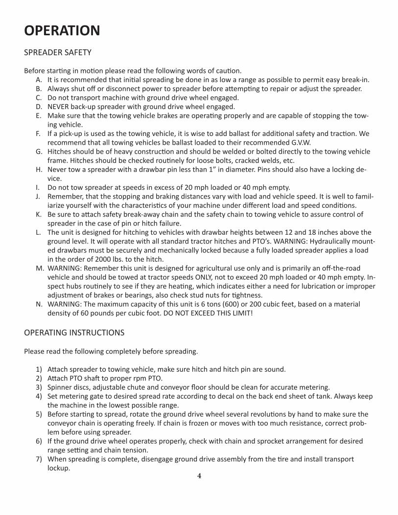
OPERATIONSPREADER SAFETY
Before starting in motion please read the following words of caution.A. It is recommended that initial spreading be done in as low a range as possible to permit easy break-in.B. Always shut off or disconnect power to spreader before attempting to repair or adjust the spreader.C. Do not transport machine with ground drive wheel engaged.D. NEVER back-up spreader with ground drive wheel engaged.E. Make sure that the towing vehicle brakes are operating properly and are capable of stopping the tow-
ing vehicle.F. If a pick-up is used as the towing vehicle, it is wise to add ballast for additional safety and traction. We
recommend that all towing vehicles be ballast loaded to their recommended G.V.W.G. Hitches should be of heavy construction and should be welded or bolted directly to the towing vehicle
frame. Hitches should be checked routinely for loose bolts, cracked welds, etc.H. Never tow a spreader with a drawbar pin less than 1” in diameter. Pins should also have a locking de-
vice.I. Do not tow spreader at speeds in excess of 20 mph loaded or 40 mph empty.J. Remember, that the stopping and braking distances vary with load and vehicle speed. It is well to famil-
iarize yourself with the characteristics of your machine under different load and speed conditions.K. Be sure to attach safety break-away chain and the safety chain to towing vehicle to assure control of
spreader in the case of pin or hitch failure.L. The unit is designed for hitching to vehicles with drawbar heights between 12 and 18 inches above the
ground level. It will operate with all standard tractor hitches and PTO’s. WARNING: Hydraulically mount-ed drawbars must be securely and mechanically locked because a fully loaded spreader applies a load in the order of 2000 lbs. to the hitch.
M. WARNING: Remember this unit is designed for agricultural use only and is primarily an off-the-road vehicle and should be towed at tractor speeds ONLY, not to exceed 20 mph loaded or 40 mph empty. In-spect hubs routinely to see if they are heating, which indicates either a need for lubrication or improper adjustment of brakes or bearings, also check stud nuts for tightness.
N. WARNING: The maximum capacity of this unit is 6 tons (600) or 200 cubic feet, based on a material density of 60 pounds per cubic foot. DO NOT EXCEED THIS LIMIT!
OPERATING INSTRUCTIONS
Please read the following completely before spreading.
1) Attach spreader to towing vehicle, make sure hitch and hitch pin are sound.2) Attach PTO shaft to proper rpm PTO.3) Spinner discs, adjustable chute and conveyor floor should be clean for accurate metering.4) Set metering gate to desired spread rate according to decal on the back end sheet of tank. Always keep
the machine in the lowest possible range.5) Before starting to spread, rotate the ground drive wheel several revolutions by hand to make sure the
conveyor chain is operating freely. If chain is frozen or moves with too much resistance, correct prob-lem before using spreader.
6) If the ground drive wheel operates properly, check with chain and sprocket arrangement for desired range setting and chain tension.
7) When spreading is complete, disengage ground drive assembly from the tire and install transport lockup.
4
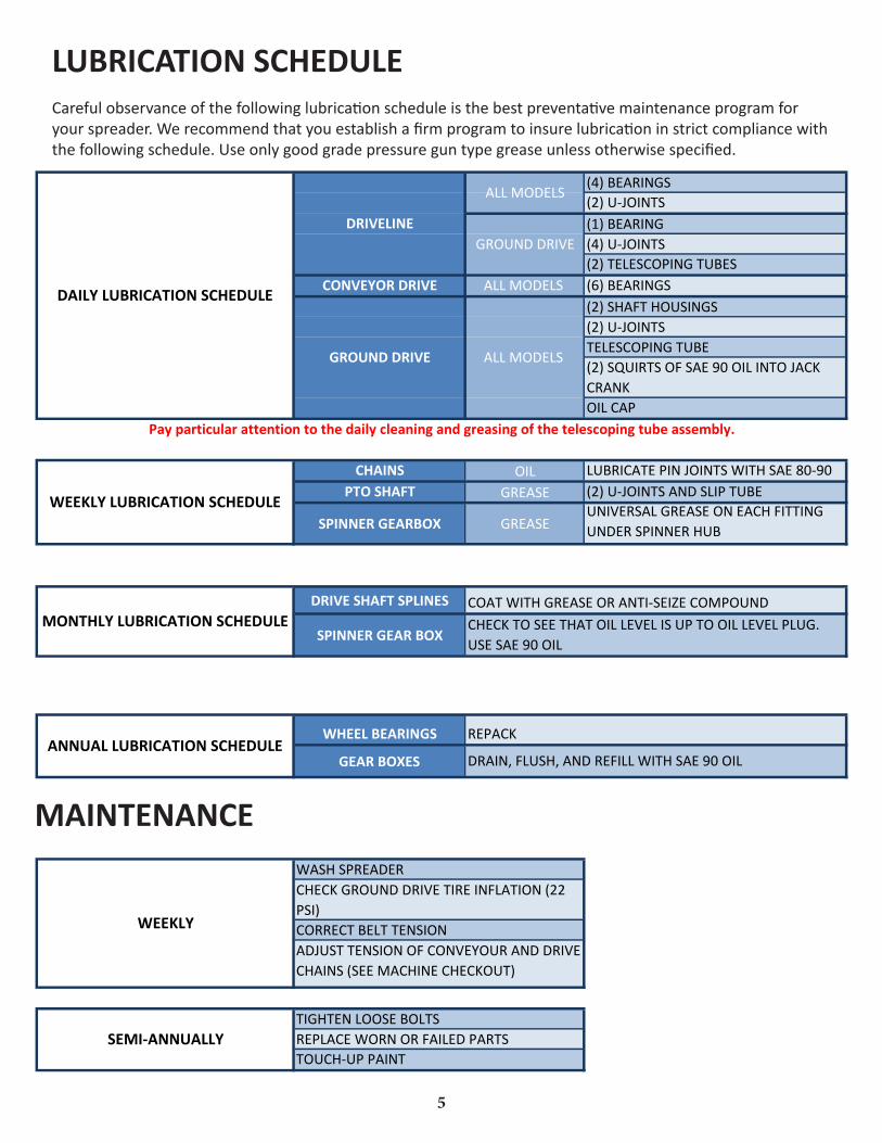
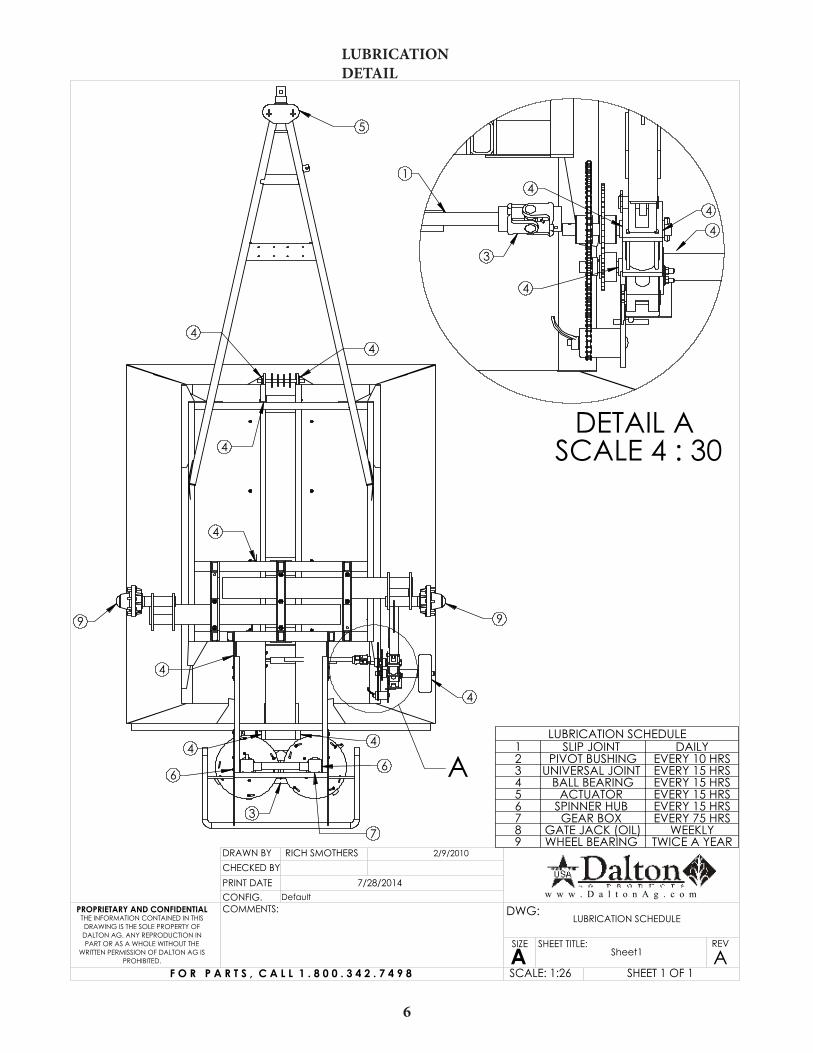
LUBRICATION SCHEDULECareful observance of the following lubrication schedule is the best preventative maintenance program for your spreader. We recommend that you establish a firm program to insure lubrication in strict compliance with the following schedule. Use only good grade pressure gun type grease unless otherwise specified.
5
(4) BEARINGS(2) U-JOINTS(1) BEARING(4) U-JOINTS(2) TELESCOPING TUBES
CONVEYOR DRIVE ALL MODELS (6) BEARINGS(2) SHAFT HOUSINGS(2) U-JOINTSTELESCOPING TUBE(2) SQUIRTS OF SAE 90 OIL INTO JACK CRANKOIL CAP
CHAINS OIL LUBRICATE PIN JOINTS WITH SAE 80-90PTO SHAFT GREASE (2) U-JOINTS AND SLIP TUBE
SPINNER GEARBOX GREASEUNIVERSAL GREASE ON EACH FITTING UNDER SPINNER HUB
DRIVE SHAFT SPLINES
SPINNER GEAR BOX
WHEEL BEARINGS
GEAR BOXES
REPLACE WORN OR FAILED PARTSTIGHTEN LOOSE BOLTS
TOUCH-UP PAINT
DAILY LUBRICATION SCHEDULE
WEEKLY LUBRICATION SCHEDULE
MONTHLY LUBRICATION SCHEDULE
ANNUAL LUBRICATION SCHEDULE
DRIVELINE
GROUND DRIVE
ALL MODELS
GROUND DRIVE
ADJUST TENSION OF CONVEYOUR AND DRIVE CHAINS (SEE MACHINE CHECKOUT)
CHECK GROUND DRIVE TIRE INFLATION (22 PSI)CORRECT BELT TENSIONWEEKLY
SEMI-ANNUALLY
WASH SPREADER
DRAIN, FLUSH, AND REFILL WITH SAE 90 OIL
Pay particular attention to the daily cleaning and greasing of the telescoping tube assembly.
ALL MODELS
COAT WITH GREASE OR ANTI-SEIZE COMPOUNDCHECK TO SEE THAT OIL LEVEL IS UP TO OIL LEVEL PLUG. USE SAE 90 OIL
REPACK
MAINTENANCE
A
99
44
4
4
4
4
446
6
7
5
3
DETAIL A SCALE 4 : 30
44
4
4
3
1
LUBRICATION SCHEDULE1 SLIP JOINT DAILY2 PIVOT BUSHING EVERY 10 HRS3 UNIVERSAL JOINT EVERY 15 HRS4 BALL BEARING EVERY 15 HRS5 ACTUATOR EVERY 15 HRS6 SPINNER HUB EVERY 15 HRS7 GEAR BOX EVERY 75 HRS8 GATE JACK (OIL) WEEKLY9 WHEEL BEARING TWICE A YEAR
CHECKED BY
Sheet1 A
RICH SMOTHERS
THE INFORMATION CONTAINED IN THIS DRAWING IS THE SOLE PROPERTY OF DALTON AG. ANY REPRODUCTION IN PART OR AS A WHOLE WITHOUT THE
WRITTEN PERMISSION OF DALTON AG IS PROHIBITED.
PROPRIETARY AND CONFIDENTIAL
DRAWN BY
CONFIG.PRINT DATE
COMMENTS: DWG:
SIZE
ASHEET TITLE: REV
SCALE: 1:26
Default7/28/2014
2/9/2010
SHEET 1 OF 1
LUBRICATION SCHEDULE
F O R P A R T S , C A L L 1 . 8 0 0 . 3 4 2 . 7 4 9 8
w w w . D a l t o n A g . c o m
LUBRICATION DETAIL
6
WHEEL BEARING ADJUSTMENT
After repacking or when inspecting wheel bearings, the following adjustment procedure should be followed. Place flat washer and spindle nut on spindle. Turn hub as you tighten nut. When a pronounced drag is felt in the bearings, back off nut one complete slot. If necessary continue to back off the nut until the next slot aligns with the cotter pin hole and install cotter pin and dust cap.
CONVEYOR CHAIN ADJUSTMENT
Loosen chain take-up locking nuts on outside of front end of trough. Adjust take-up bolts evenly until chain clears main frame members and axle tube by ¾” ½”. Inspect shaft bearing mounting bolts and shaft locking col-lars for tightness of set screws (6 places). Reset take-up locking nuts.
STORAGE
Before storing the spreader for more than a few days, the machine should be emptied completely and thor-oughly washed both inside and out. This precaution will minimize the severity of fertilizer acid corrosion, extend the useful life of the machine, and prevent damage to drive line and conveyor chain from fertilizer com-paction and caking. We further recommend that the machine be thoroughly greased after washing.
Before operating the machine after extended periods of storage, re-lubricate the entire spreader in accordance with the lubrication section of this manual. Also check the entire spreader, following the New Machine Check-out Procedure to be found in a foregoing section of the manual.
Remember that oil and grease are your least expensive corrosion inhibitors.
MACHINE ADJUSTMENT
7
ADDITIONAL INSTRUCTIONS
The ground drive is equipped with the following sprocket combinations: Low Range Drive Chain on 12 & 72 Tooth Sprockets
High Range Drive Chain on 24 & 48 Tooth Sprockets
CAUTION
Do not operate your spreader with less than one and a half (1 ½) inch of metering gate opening as material will compact against metering gate and cause failure of the conveyor chain.
CAUTION
Do not disconnect implement from tractor with material remaining in box.
8

SPREAD ADJUSTMENT AND APPLICATION RATES
For accurate and precise spreading rates, it is necessary that you know the weight in pounds per cubic foot of the material to be spread. If this is not known, the weight can be quickly and accurately determined by the following method:
1. Weigh an empty one gallon container.2. Fill level full with the material to be used.3. Weigh container and material, and then subtract the weight of the container to obtain the weight
of the material.4. Multiply the weight of the material by 7.5 to obtain the weight of the material in pounds per cubic
foot.Example: Typical Material-Potash
1) Weight of empty one gallon container 1.00 lbs.2) Weight of filled container 10.35 lbs.3) Weight of container (net) 9.35 lbs.4) 9.35 X 7.5 70.125 lbs. /cu ft.
You would therefore use the column on the Spread Chart headed 70 to determine the proper gate opening for the desired application rate.
You’re Mobility Spreader with its heavy-duty distributor discs and blades will apply most materials in a 50 foot wide swath.
9

An operational characteristic of this type of machine is the possibility of overloading the distributors at high rates of application. Such an overload results in an alteration of the spread pattern to a nar-rower swath with heavier application at the center. This can be avoided by reducing speed when using high application rates. MOBILITY DISTRIBUTORS ARE DESIGNED FOR A MAXIMUM APPLICATION RATE OF 1500 POUNDS PER MINUTE OF AVERAGE 60 POUND PER CUBIC FOOT MATERIAL. Caution: Be extra careful to check your spread pattern when using high application rates. Adjust your driving pattern to the actual delivered spread swath, the adjustment of the machine, and the material being used. Recom-mended ground or travel speed for most application rates (up to 700 pounds per acre) is 8 mph. When application rates are in excess of 700 pounds per acre, the ground speed should be proportionately reduced, (for example, at 1400 pounds per acre, maximum ground speed should be 4 mph.) We recom-mend that for very high application rates, to insure uniformity of application, that two lighter applica-tion passes be made preferably placing your second pass over the lap lines of the first pass. This also is recommended practice when spreading under very windy conditions or with a material that segregates easily. If your effective spread pattern is more than 50 feet wide the Metering Gate setting should be increased proportionately, according to the percentage of your spread width in excess of 50 feet. The gate setting should likewise be decreased if your effective spread pattern is less than 50 feet. EXAMPLE: 60 foot effective spread width—increase gate setting from Spread Chart by 20%; 40 foot effective spread pattern width—decrease your gate setting from Spread Chart setting by 20%. Your spread pattern can be checked accurately and visually on a freshly worked, level area of ground. Such an area is also ideally suited to adjusting and fine tuning your machine. The following diagram graphically illustrates a typical spread pattern.
Note on the illustration below that the lap point occurs at the point where the application rate is one-half of the spread chart rate. The profile of the spread pattern tapers at both edges and has a wide uniform area in the center. By careful attention to the lap point during application, a very uniform and even spread rate can be attained. The Mobility Spreaders have been designed to provide this good and uniform tapered profile to make spread width less critical. However, excessive or insufficient overlap of passes will result in a poor application pattern in the lap area of the total spread pattern. If you can at-tain this spread pattern and pay careful attention to the lap points, the dotted line on the illustration will represent your actual overall spread pattern.
EFFECTIVE SPREAD PATTERN WIDTH
OVERLAP
SINGLE PASS SPREAD PATTERN
SPREAD CHART APPLICATION
RATE
LAP POINT
RESULTING OVERALL SPREAD PATTERN
SPREAD PATTERN DETAILS
10

STANDARD SPREAD SETUP
1 53
97
42
68
VIEWED FROM BACK OF SPREADER
ROTATIONROTATION
STANDARD SPREAD, BLADE SETUP# PART NUMBER QTY.1 1003727 DISTRIBUTOR DISC 2
2 MS 1001662 EXTRA LONG DISTRIBUTOR BLADE, 8, RIGHT 1
3 MS 1001705 EXTRA LONG DISTRIBUTOR BLADE, 8, LEFT 1
4 MS 1001718 7 INCH DISTRIBUTOR BLADE, RIGHT 1
5 MS 1001719 7 INCH DISTRIBUTOR BLADE, LEFT 1
6 MS 1001924 4.375 DISTRIBUTOR BLADE, RIGHT 1
7 MS 1001925 4.375 DISTRIBUTOR BLADE, LEFT 1
8 MS 1001926 DISTRIBUTOR BLADE, 5.5, RIGHT 1
9 MS 1001927 DISTRIBUTOR BLADE, 5.5, LEFT 1
CHECKED BY
Sheet1 A
RICH SMOTHERS
THE INFORMATION CONTAINED IN THIS DRAWING IS THE SOLE PROPERTY OF DALTON AG. ANY REPRODUCTION IN PART OR AS A WHOLE WITHOUT THE
WRITTEN PERMISSION OF DALTON AG IS PROHIBITED.
PROPRIETARY AND CONFIDENTIAL
DRAWN BY
CONFIG.PRINT DATE
COMMENTS: DWG:
SIZE
ASHEET TITLE: REV
SCALE: 1:6
STANDARD SPREAD PATERN, BLADE SETUP7/28/2014
9/16/2013
SHEET 1 OF 1
STANDARD SPREAD, BLADE SETUP
F O R P A R T S , C A L L 1 . 8 0 0 . 3 4 2 . 7 4 9 8
w w w . D a l t o n A g . c o m
11
1
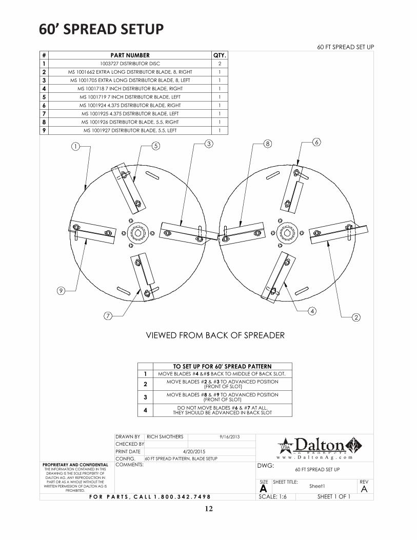
60’ SPREAD SETUP
1 5 3
9
74
2
68
VIEWED FROM BACK OF SPREADER
60 FT SPREAD SET UP# PART NUMBER QTY.1 1003727 DISTRIBUTOR DISC 2
2 MS 1001662 EXTRA LONG DISTRIBUTOR BLADE, 8, RIGHT 1
3 MS 1001705 EXTRA LONG DISTRIBUTOR BLADE, 8, LEFT 1
4 MS 1001718 7 INCH DISTRIBUTOR BLADE, RIGHT 1
5 MS 1001719 7 INCH DISTRIBUTOR BLADE, LEFT 1
6 MS 1001924 4.375 DISTRIBUTOR BLADE, RIGHT 1
7 MS 1001925 4.375 DISTRIBUTOR BLADE, LEFT 1
8 MS 1001926 DISTRIBUTOR BLADE, 5.5, RIGHT 1
9 MS 1001927 DISTRIBUTOR BLADE, 5.5, LEFT 1
TO SET UP FOR 60' SPREAD PATTERN1 MOVE BLADES #4  BACK TO MIDDLE OF BACK SLOT.
2 MOVE BLADES #2 & #3 TO ADVANCED POSITION (FRONT OF SLOT)
3 MOVE BLADES #8 & #9 TO ADVANCED POSITION (FRONT OF SLOT)
4 DO NOT MOVE BLADES #6 & #7 AT ALL. THEY SHOULD BE ADVANCED IN BACK SLOT
CHECKED BY
Sheet1 A
RICH SMOTHERS
THE INFORMATION CONTAINED IN THIS DRAWING IS THE SOLE PROPERTY OF DALTON AG. ANY REPRODUCTION IN PART OR AS A WHOLE WITHOUT THE
WRITTEN PERMISSION OF DALTON AG IS PROHIBITED.
PROPRIETARY AND CONFIDENTIAL
DRAWN BY
CONFIG.PRINT DATE
COMMENTS: DWG:
SIZE
ASHEET TITLE: REV
SCALE: 1:6
60 FT SPREAD PATTERN, BLADE SETUP4/20/2015
9/16/2013
SHEET 1 OF 1
60 FT SPREAD SET UP
F O R P A R T S , C A L L 1 . 8 0 0 . 3 4 2 . 7 4 9 8
w w w . D a l t o n A g . c o m
12
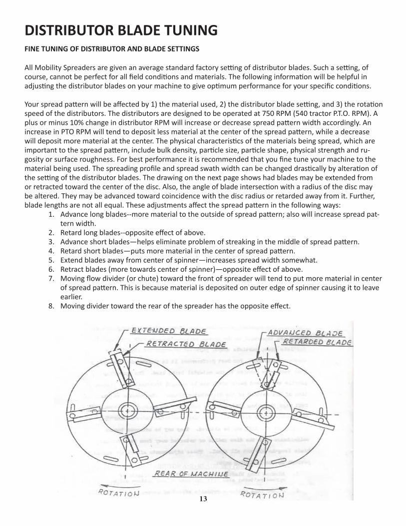
FINE TUNING OF DISTRIBUTOR AND BLADE SETTINGS
All Mobility Spreaders are given an average standard factory setting of distributor blades. Such a setting, of course, cannot be perfect for all field conditions and materials. The following information will be helpful in adjusting the distributor blades on your machine to give optimum performance for your specific conditions.
Your spread pattern will be affected by 1) the material used, 2) the distributor blade setting, and 3) the rotation speed of the distributors. The distributors are designed to be operated at 750 RPM (540 tractor P.T.O. RPM). A plus or minus 10% change in distributor RPM will increase or decrease spread pattern width accordingly. An increase in PTO RPM will tend to deposit less material at the center of the spread pattern, while a decrease will deposit more material at the center. The physical characteristics of the materials being spread, which are important to the spread pattern, include bulk density, particle size, particle shape, physical strength and ru-gosity or surface roughness. For best performance it is recommended that you fine tune your machine to the material being used. The spreading profile and spread swath width can be changed drastically by alteration of the setting of the distributor blades. The drawing on the next page shows had blades may be extended from or retracted toward the center of the disc. Also, the angle of blade intersection with a radius of the disc may be altered. They may be advanced toward coincidence with the disc radius or retarded away from it. Further, blade lengths are not all equal. These adjustments affect the spread pattern in the following ways:
1. Advance long blades--more material to the outside of spread pattern; also will increase spread pat-tern width.
2. Retard long blades--opposite effect of above.3. Advance short blades—helps eliminate problem of streaking in the middle of spread pattern.4. Retard short blades—puts more material in the center of spread pattern.5. Extend blades away from center of spinner—increases spread width somewhat.6. Retract blades (more towards center of spinner)—opposite effect of above.7. Moving flow divider (or chute) toward the front of spreader will tend to put more material in center
of spread pattern. This is because material is deposited on outer edge of spinner causing it to leave earlier.
8. Moving divider toward the rear of the spreader has the opposite effect.
DISTRIBUTOR BLADE TUNING
13
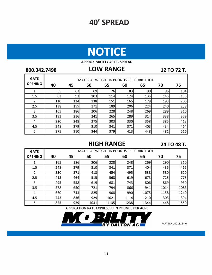
40’ SPREAD
14
800.342.7498 LOW RANGE 12 TO 72 T.
40 45 50 55 60 65 70 751 55 63 69 76 83 90 96 104
1.5 83 93 103 114 124 135 145 1552 110 124 138 151 165 179 193 206
2.5 138 155 171 189 206 224 240 2583 165 186 206 228 248 269 289 310
3.5 193 216 241 265 289 314 338 3594 220 248 275 303 330 358 385 413
4.5 248 279 310 341 371 403 434 4645 275 310 344 379 413 448 481 516
HIGH RANGE 24 TO 48 T.
40 45 50 55 60 65 70 751 165 186 206 228 248 269 290 310
1.5 248 279 310 341 371 404 435 4652 330 371 413 454 495 538 580 620
2.5 413 464 515 568 619 673 725 7753 495 558 619 681 743 806 869 930
3.5 578 650 721 794 866 941 1014 10854 660 743 825 908 990 1075 1158 1240
4.5 743 836 929 1021 1114 1210 1303 13945 825 929 1031 1135 1238 1344 1448 1550
APPLICATION RATE EXPRESSED IN POUNDS PER ACRE
PART NO. 1001118-40
NOTICEAPPROXIMATELY 40 FT. SPREAD
GATE OPENING
MATERIAL WEIGHT IN POUNDS PER CUBIC FOOT
GATE OPENING
MATERIAL WEIGHT IN POUNDS PER CUBIC FOOT
15
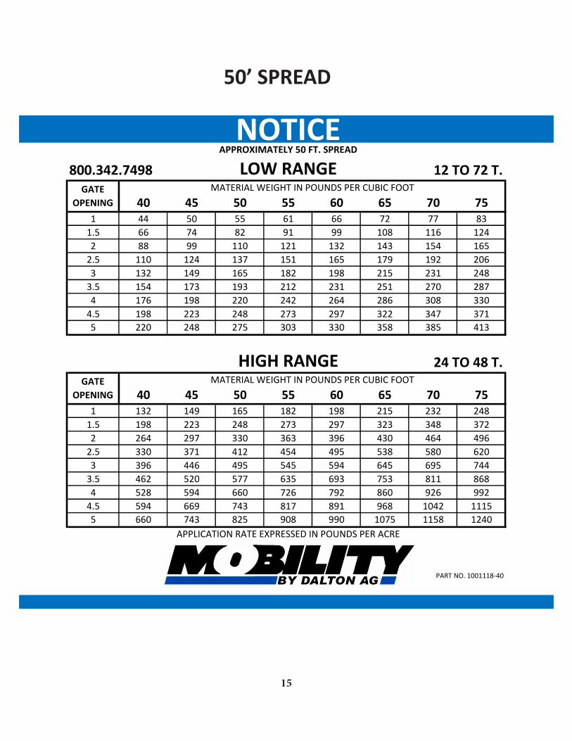
50’ SPREAD
800.342.7498 LOW RANGE 12 TO 72 T.
40 45 50 55 60 65 70 751 44 50 55 61 66 72 77 83
1.5 66 74 82 91 99 108 116 1242 88 99 110 121 132 143 154 165
2.5 110 124 137 151 165 179 192 2063 132 149 165 182 198 215 231 248
3.5 154 173 193 212 231 251 270 2874 176 198 220 242 264 286 308 330
4.5 198 223 248 273 297 322 347 3715 220 248 275 303 330 358 385 413
HIGH RANGE 24 TO 48 T.
40 45 50 55 60 65 70 751 132 149 165 182 198 215 232 248
1.5 198 223 248 273 297 323 348 3722 264 297 330 363 396 430 464 496
2.5 330 371 412 454 495 538 580 6203 396 446 495 545 594 645 695 744
3.5 462 520 577 635 693 753 811 8684 528 594 660 726 792 860 926 992
4.5 594 669 743 817 891 968 1042 11155 660 743 825 908 990 1075 1158 1240
APPLICATION RATE EXPRESSED IN POUNDS PER ACRE
PART NO. 1001118-40
NOTICEAPPROXIMATELY 50 FT. SPREAD
GATE OPENING
MATERIAL WEIGHT IN POUNDS PER CUBIC FOOT
GATE OPENING
MATERIAL WEIGHT IN POUNDS PER CUBIC FOOT

16
800.342.7498 LOW RANGE 12 TO 72 T.
40 45 50 55 60 65 70 751 37 42 46 51 60 60 64 69
1.5 55 62 68 76 90 90 97 1032 73 82 92 101 119 119 128 137
2.5 92 103 114 126 149 149 160 1723 110 124 137 152 179 179 192 207
3.5 128 144 161 177 209 209 225 2394 147 165 183 202 238 238 257 275
4.5 165 186 207 227 268 268 289 3095 183 207 229 252 298 298 321 344
HIGH RANGE 24 TO 48 T.
40 45 50 55 60 65 70 751 110 124 137 152 165 179 193 207
1.5 165 186 207 227 247 269 290 3102 220 247 275 302 330 358 387 413
2.5 275 309 343 378 412 448 483 5173 330 372 412 454 495 537 579 620
3.5 385 433 481 529 577 627 676 7234 440 495 550 605 660 717 772 827
4.5 495 557 619 681 742 807 868 9295 550 619 687 757 825 896 956 1033
APPLICATION RATE EXPRESSED IN POUNDS PER ACRE
PART NO. 1001118-40
NOTICEAPPROXIMATELY 60 FT. SPREAD
GATE OPENING
MATERIAL WEIGHT IN POUNDS PER CUBIC FOOT
GATE OPENING
MATERIAL WEIGHT IN POUNDS PER CUBIC FOOT
60’ SPREAD
17
7
1314
21
22
1615
10
24
3
11
8
10
2
12
9
23
5
2017
18
3
57
3
3
2
10
25
4
2627
22B
STANDARD:4420532 HD CLEVIS
OPTIONAL:4440918 BULL PULL HITCH, CAT 4 19
14B
19BFOR 1000 PTO
FOR 1000 PTOFOR 540 PTO
FOR 540 PTO
REVISIONS
REV. DESCRIPTION DATE APPROVED
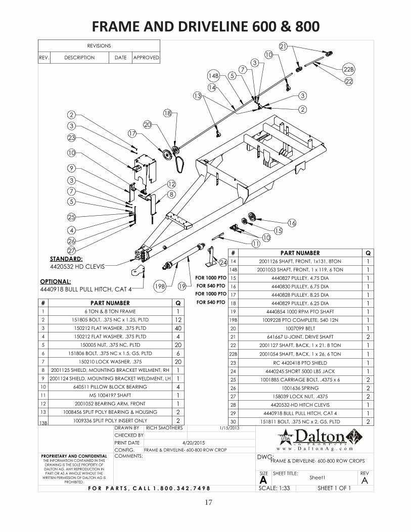
# PART NUMBER Q1 6 TON & 8 TON FRAME 12 151805 BOLT, .375 NC x 1.25, PLTD 123 150212 FLAT WASHER, .375 PLTD 404 150212 FLAT WASHER, .375 PLTD 45 150005 NUT, .375 NC, PLTD 206 151806 BOLT, .375 NC x 1.5, G5, PLTD 67 150210 LOCK WASHER, .375 208 2001125 SHIELD, MOUNTING BRACKET WELMENT, RH 19 2001124 SHIELD, MOUNTING BRACKET WELDMENT, LH 110 640511 PILLOW BLOCK BEARING 411 MS 1004197 SHAFT 112 2001052 BEARING ARM, FRONT 113 1008456 SPLIT POLY BEARING & HOUSING 2
13B 1009336 SPLIT POLY INSERT ONLY 2
# PART NUMBER Q14 2001126 SHAFT, FRONT, 1x131, 8TON 1
14B 2001053 SHAFT, FRONT, 1 x 119, 6 TON 115 4440827 PULLEY, 4.75 DIA 116 4440830 PULLEY, 6.75 DIA 117 4440828 PULLEY, 8.25 DIA 118 4440829 PULLEY, 6.25 DIA 119 4440854 1000 RPM PTO SHAFT 1
19B 1009228 PTO COMPLETE, 540 12N 120 1007099 BELT 121 641667 U-JOINT, DRIVE SHAFT 222 2001127 SHAFT, BACK, 1 x 21, 8 TON 1
22B 2001054 SHAFT, BACK, 1 x 26, 6 TON 123 RC 4420418 PTO SHIELD 124 4440245 SHORT 5000 LBS JACK 125 1001885 CARRIAGE BOLT, .4375 x 6 226 1001636 SPRING 227 158039 LOCK NUT, .4375 228 4420532-HD HITCH CLEVIS 129 4440918 BULL PULL HITCH, CAT 4 130 151811 BOLT, .375 NC x 2, G5, PLTD 2
CHECKED BY
Sheet1 A
RICH SMOTHERS
THE INFORMATION CONTAINED IN THIS DRAWING IS THE SOLE PROPERTY OF DALTON AG. ANY REPRODUCTION IN PART OR AS A WHOLE WITHOUT THE
WRITTEN PERMISSION OF DALTON AG IS PROHIBITED.
PROPRIETARY AND CONFIDENTIAL
DRAWN BY
CONFIG.PRINT DATE
COMMENTS: DWG:
SIZE
ASHEET TITLE: REV
SCALE: 1:33
FRAME & DRIVELINE- 600-800 ROW CROP4/20/2015
1/15/2013
SHEET 1 OF 1
FRAME & DRIVELINE- 600-800 ROW CROPS
F O R P A R T S , C A L L 1 . 8 0 0 . 3 4 2 . 7 4 9 8
w w w . D a l t o n A g . c o m
FRAME AND DRIVELINE 600 & 800
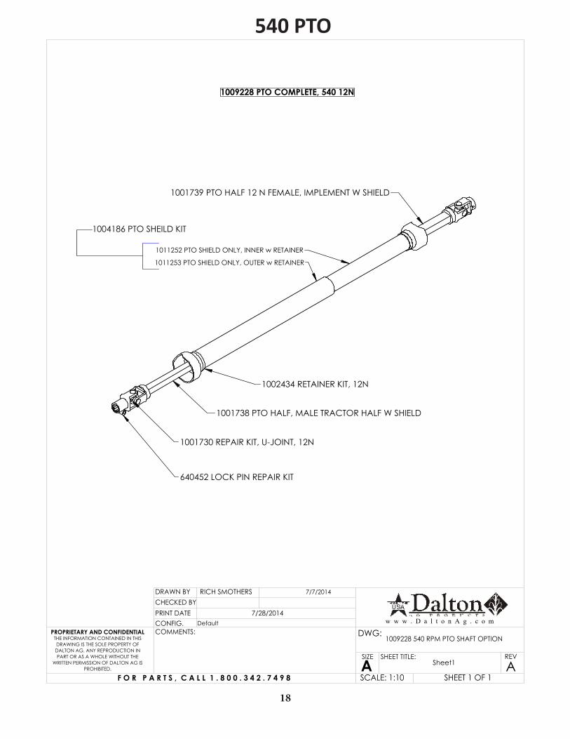
1001739 PTO HALF 12 N FEMALE, IMPLEMENT W SHIELD
1001738 PTO HALF, MALE TRACTOR HALF W SHIELD
1011253 PTO SHIELD ONLY, OUTER w RETAINER
1011252 PTO SHIELD ONLY, INNER w RETAINER
1001730 REPAIR KIT, U-JOINT, 12N
1002434 RETAINER KIT, 12N
1009228 PTO COMPLETE, 540 12N
640452 LOCK PIN REPAIR KIT
1004186 PTO SHEILD KIT
CHECKED BY
Sheet1 A
RICH SMOTHERS
THE INFORMATION CONTAINED IN THIS DRAWING IS THE SOLE PROPERTY OF DALTON AG. ANY REPRODUCTION IN PART OR AS A WHOLE WITHOUT THE
WRITTEN PERMISSION OF DALTON AG IS PROHIBITED.
PROPRIETARY AND CONFIDENTIAL
DRAWN BY
CONFIG.PRINT DATE
COMMENTS: DWG:
SIZE
ASHEET TITLE: REV
SCALE: 1:10
Default7/28/2014
7/7/2014
SHEET 1 OF 1
1009228 540 RPM PTO SHAFT OPTION
F O R P A R T S , C A L L 1 . 8 0 0 . 3 4 2 . 7 4 9 8
w w w . D a l t o n A g . c o m
540 PTO
18

1001739 PTO HALF 12 N FEMALE, IMPLEMENT W SHIELD
4440853 PTO HALF, MALE, TRACTOR
1011253 PTO SHIELD ONLY, OUTER w RETAINER
1011252 PTO SHIELD ONLY, INNER w RETAINER
1001730 REPAIR KIT, U-JOINT, 12N
1002434 RETAINER KIT, 12N
4440854 1000 RPM PTO SHAFT
1011258 PTO KIT, SNAP HITCH 1000 RPM
1004186 PTO SHEILD KIT
CHECKED BY
Sheet1 A
RICH SMOTHERS
THE INFORMATION CONTAINED IN THIS DRAWING IS THE SOLE PROPERTY OF
CMC-DALTON AG. ANY REPRODUCTION IN PART OR AS A WHOLE WITHOUT THE WRITTEN PERMISSION OF CMC-DALTON
AG IS PROHIBITED.
PROPRIETARY AND CONFIDENTIAL
DRAWN BY
CONFIG.PRINT DATE
COMMENTS: DWG:
SIZE
ASHEET TITLE: REV
SCALE: 1:10
Default7/28/2014
7/7/2014
SHEET 1 OF 1
4440854 1000 RPM PTO SHAFT
F O R P A R T S , C A L L 1 . 8 0 0 . 3 4 2 . 7 4 9 8
w w w . D a l t o n A g . c o m
4440854 1000 RPM PTO SHAFT
1000 PTO
19
20
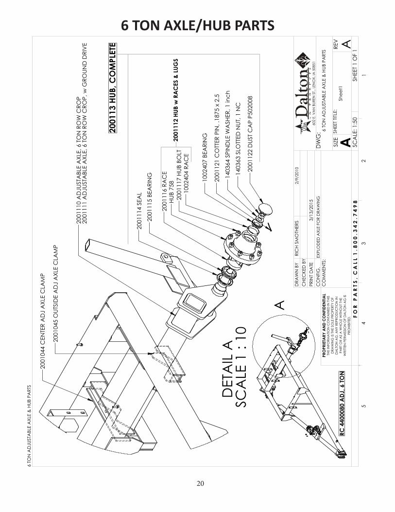
A
RC 4
4000
80 A
DJ, 6
TON
DET
AIL
A
SCA
LE 1
: 10
2001
044
CEN
TER
AD
J A
XLE
CLA
MP
2001
045
OUT
SID
E A
DJ
AXL
E C
LAM
P
2001
110
AD
JUST
ABL
E A
XLE,
6 T
ON
RO
W C
ROP
2001
111
AD
JUST
ABL
E A
XLE,
6 T
ON
RO
W C
ROP,
w G
ROUN
D D
RIV
E
2001
122
DUS
T C
AP
P502
008
1403
63 S
LOTT
ED N
UT, 1
NC
2001
121
CO
TTER
PIN
, .18
75 x
2.5
1403
64 S
PIN
DLE
WA
SHER
, 1 in
ch
1002
407
BEA
RIN
G
1002
404
RAC
E
HUB
758
2001
116
RAC
E
2001
115
BEA
RIN
G
2001
114
SEA
L
2001
13 H
UB, C
OM
PLET
E
2001
112
HUB
w R
AC
ES &
LUG
S20
0111
7 HU
B BO
LT
6 TO
N A
DJU
STA
BLE
AXL
E &
HUB
PA
RTS
SHEE
T 1 O
F 1
2/9/
2010
3/13
/201
5EX
PLO
DED
AXL
E FO
R D
RAW
ING
SCA
LE: 1
:50
REV
SHEE
T TIT
LE:
ASIZE
DW
G:
CO
MM
ENTS
:
PRIN
T D
ATE
CO
NFI
G.
DRA
WN
BY
PRO
PRIE
TARY
AN
D C
ON
FIDE
NTIA
LTH
E IN
FORM
ATIO
N C
ON
TAIN
ED IN
THI
S D
RAW
ING
IS T
HE S
OLE
PRO
PERT
Y O
F D
ALT
ON
AG
. AN
Y RE
PRO
DUC
TION
IN
PART
OR
AS
A W
HOLE
WITH
OUT
THE
W
RITT
EN P
ERM
ISSI
ON
OF
DA
LTO
N A
G IS
PR
OHI
BITE
D.
54
32
1
RIC
H SM
OTH
ERS
A
602
E. V
AN
BUR
EN S
T., L
ENO
X, IA
508
51
Shee
t1
CHE
CKE
D B
Y
F O
R
P A
R T
S ,
C A
L L
1 . 8
0 0
. 3
4 2
. 7 4
9 8
6 TO
N A
DJU
STA
BLE
AXL
E &
HUB
PA
RTS
6 TON AXLE/HUB PARTS
21
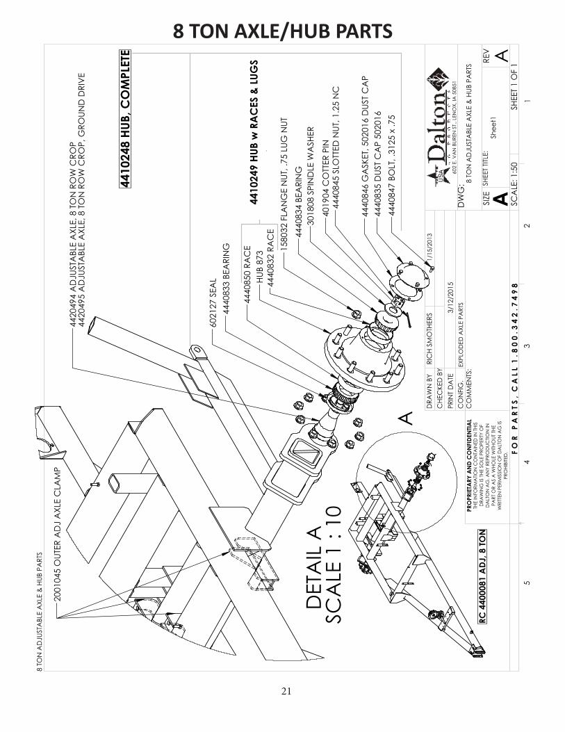
A
RC 4
4000
81 A
DJ, 8
TON
DET
AIL
A
SCA
LE 1
: 10
2001
045
OUT
ER A
DJ
AXL
E C
LAM
P
4420
494
AD
JUST
ABL
E A
XLE,
8 T
ON
RO
W C
ROP
4420
495
AD
JUST
ABL
E A
XLE,
8 T
ON
RO
W C
ROP,
GRO
UND
DRI
VE
4440
847
BOLT
, .31
25 x
.75
4440
835
DUS
T C
AP
5020
1644
4084
6 G
ASK
ET, 5
0201
6 D
UST
CA
P
4440
845
SLO
TTED
NUT
, 1.2
5 N
C40
1904
CO
TTER
PIN
3018
08 S
PIN
DLE
WA
SHER
4440
834
BEA
RIN
G
4440
832
RAC
EHU
B 87
3
4440
833
BEA
RIN
G60
2127
SEA
L
4440
850
RAC
E
4410
248
HUB,
CO
MPL
ETE
4410
249
HUB
w R
AC
ES &
LUG
S
1580
32 F
LAN
GE
NUT
, .75
LUG
NUT
8 TO
N A
DJU
STA
BLE
AXL
E &
HUB
PA
RTS
SHEE
T 1 O
F 1
1/15
/201
3
3/12
/201
5EX
PLO
DED
AXL
E PA
RTS
SCA
LE: 1
:50
REV
SHEE
T TIT
LE:
ASIZE
DW
G:
CO
MM
ENTS
:
PRIN
T D
ATE
CO
NFI
G.
DRA
WN
BY
PRO
PRIE
TARY
AN
D C
ON
FIDE
NTIA
LTH
E IN
FORM
ATIO
N C
ON
TAIN
ED IN
THI
S D
RAW
ING
IS T
HE S
OLE
PRO
PERT
Y O
F D
ALT
ON
AG
. AN
Y RE
PRO
DUC
TION
IN
PART
OR
AS
A W
HOLE
WITH
OUT
THE
W
RITT
EN P
ERM
ISSI
ON
OF
DA
LTO
N A
G IS
PR
OHI
BITE
D.
54
32
1
RIC
H SM
OTH
ERS
A
602
E. V
AN
BUR
EN S
T., L
ENO
X, IA
508
51
Shee
t1
CHE
CKE
D B
Y
F O
R
P A
R T
S ,
C A
L L
1 . 8
0 0
. 3
4 2
. 7 4
9 8
8 TO
N A
DJU
STA
BLE
AXL
E &
HUB
PA
RTS8 TON AXLE/HUB PARTS
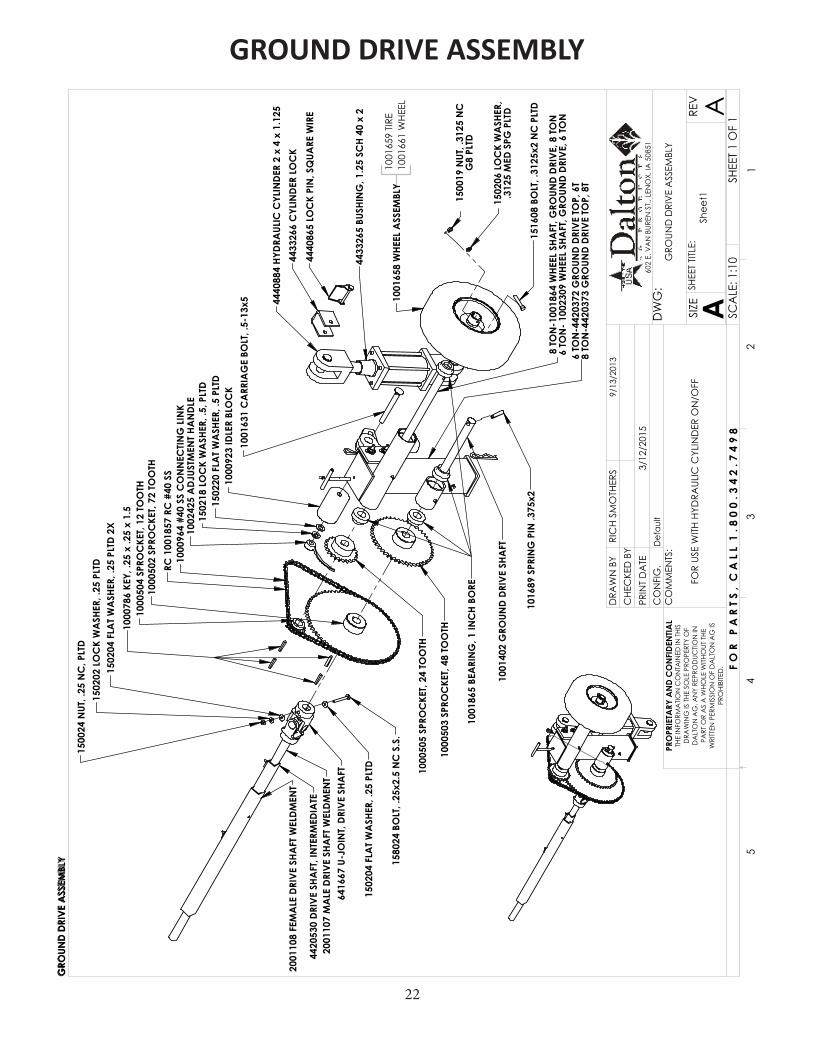
22
1580
24 B
OLT
, .25
x2.5
NC
S.S
.
1502
04 F
LAT W
ASH
ER, .
25 P
LTD
2X
1500
24 N
UT, .
25 N
C, P
LTD
1000
502
SPRO
CKE
T, 72
TOO
THRC
100
1857
RC
#40
SS
1000
504
SPRO
CKE
T, 12
TOO
TH
1000
505
SPRO
CKE
T, 24
TOO
TH
1002
425
ADJ
USTM
ENT H
AN
DLE
1502
18 L
OC
K W
ASH
ER, .
5, P
LTD
1000
503
SPRO
CKE
T, 48
TOO
TH
8 TO
N-1
0018
64 W
HEEL
SHA
FT, G
ROUN
D DR
IVE,
8 TO
N6
TON
- 100
2309
WHE
EL S
HAFT
, GRO
UND
DRIV
E, 6
TON
1001
402
GRO
UND
DRIV
E SH
AFT
1001
865
BEA
RIN
G, 1
INC
H BO
RE
1502
20 F
LAT W
ASH
ER, .
5 PL
TD
1016
89 S
PRIN
G P
IN .3
75x2
1516
08 B
OLT
, .31
25x2
NC
PLT
D
1001
658
WHE
EL A
SSEM
BLY
1502
06 L
OC
K W
ASH
ER,
.312
5 M
ED S
PG P
LTD
1500
19 N
UT, .
3125
NC
G
8 PL
TD
1502
02 L
OC
K W
ASH
ER, .
25 P
LTD
1001
631
CA
RRIA
GE
BOLT
, .5-
13x5
1000
923
IDLE
R BL
OC
K
2001
108
FEM
ALE
DRI
VE S
HAFT
WEL
DMEN
T
2001
107
MA
LE D
RIVE
SHA
FT W
ELDM
ENT
4420
530
DRIV
E SH
AFT
, IN
TERM
EDIA
TE
1001
659
TIRE
1001
661
WHE
EL
6 TO
N-4
4203
72 G
ROUN
D DR
IVE
TOP,
6T
8 TO
N-4
4203
73 G
ROUN
D DR
IVE
TOP,
8T
GRO
UND
DRIV
E A
SSEM
BLY
1502
04 F
LAT W
ASH
ER, .
25 P
LTD
1000
964
#40
SS C
ON
NEC
TING
LIN
K
6416
67 U
-JO
INT,
DRIV
E SH
AFT
4433
266
CYL
INDE
R LO
CK
4440
865
LOC
K PI
N, S
QUA
RE W
IRE
4440
884
HYDR
AUL
IC C
YLIN
DER
2 x
4 x
1.12
5
4433
265
BUSH
ING
, 1.2
5 SC
H 40
x 2
1000
786
KEY,
.25
x .2
5 x
1.5
FOR
USE
WITH
HYD
RAUL
IC C
YLIN
DER
ON
/OFF
GRO
UND
DRI
VE
ASS
EMBL
Y
SHEE
T 1 O
F 1
9/13
/201
3
3/12
/201
5D
efau
lt
SCA
LE: 1
:10
REV
SHEE
T TIT
LE:
ASIZE
DW
G:
CO
MM
ENTS
:
PRIN
T D
ATE
CO
NFI
G.
DRA
WN
BY
PRO
PRIE
TARY
AN
D C
ON
FIDE
NTIA
LTH
E IN
FORM
ATIO
N C
ON
TAIN
ED IN
THI
S D
RAW
ING
IS T
HE S
OLE
PRO
PERT
Y O
F D
ALT
ON
AG
. AN
Y RE
PRO
DUC
TION
IN
PART
OR
AS
A W
HOLE
WITH
OUT
THE
W
RITT
EN P
ERM
ISSI
ON
OF
DA
LTO
N A
G IS
PR
OHI
BITE
D.
54
32
1
RIC
H SM
OTH
ERS
A
602
E. V
AN
BUR
EN S
T., L
ENO
X, IA
508
51
Shee
t1
CHE
CKE
D B
Y
F O
R
P A
R T
S ,
C A
L L
1 . 8
0 0
. 3
4 2
. 7 4
9 8
GRO
UND
DRI
VE
ASS
EMBL
YGROUND DRIVE ASSEMBLY
23
3
1111213
10
8
6
5
7
9
4
2
**OPTIONAL TARP ITEMS
6B
REVISIONS
REV. DESCRIPTION DATE APPROVED
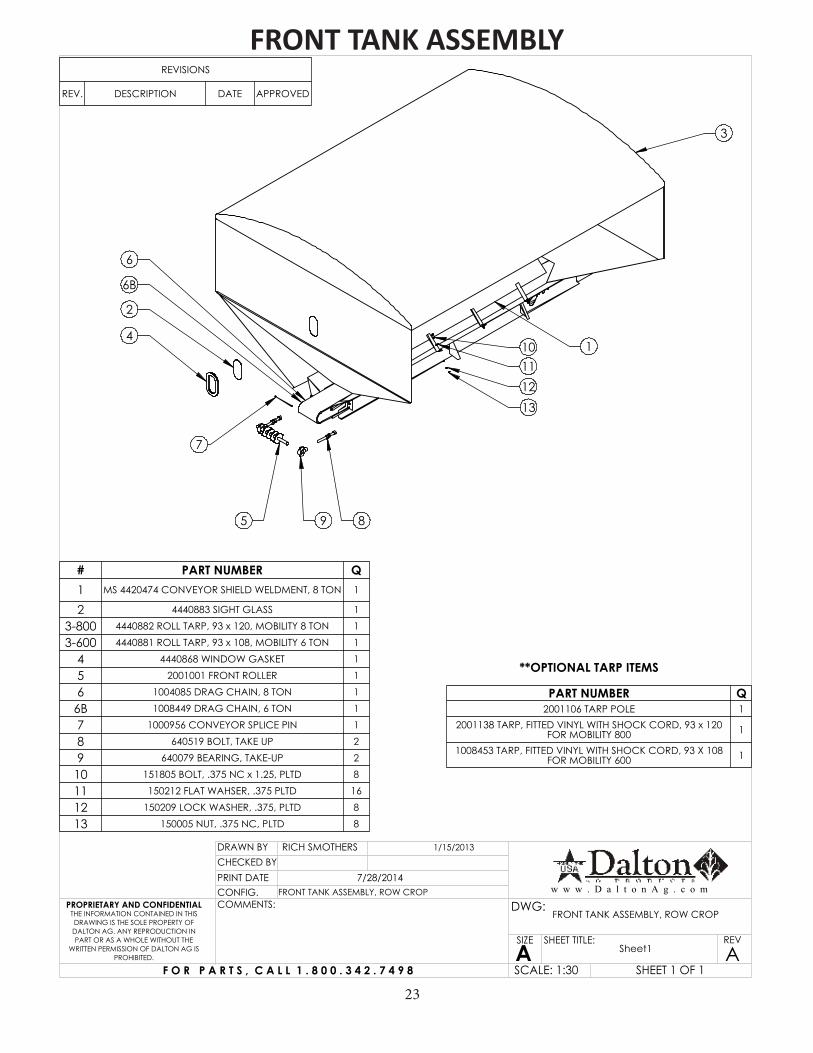
# PART NUMBER Q1 MS 4420474 CONVEYOR SHIELD WELDMENT, 8 TON 1
2 4440883 SIGHT GLASS 1
3-800 4440882 ROLL TARP, 93 x 120, MOBILITY 8 TON 1
3-600 4440881 ROLL TARP, 93 x 108, MOBILITY 6 TON 1
4 4440868 WINDOW GASKET 1
5 2001001 FRONT ROLLER 1
6 1004085 DRAG CHAIN, 8 TON 1
6B 1008449 DRAG CHAIN, 6 TON 1
7 1000956 CONVEYOR SPLICE PIN 1
8 640519 BOLT, TAKE UP 2
9 640079 BEARING, TAKE-UP 2
10 151805 BOLT, .375 NC x 1.25, PLTD 8
11 150212 FLAT WAHSER, .375 PLTD 16
12 150209 LOCK WASHER, .375, PLTD 8
13 150005 NUT, .375 NC, PLTD 8
PART NUMBER Q2001106 TARP POLE 1
2001138 TARP, FITTED VINYL WITH SHOCK CORD, 93 x 120 FOR MOBILITY 800 1
1008453 TARP, FITTED VINYL WITH SHOCK CORD, 93 X 108 FOR MOBILITY 600 1
CHECKED BY
Sheet1 A
RICH SMOTHERS
THE INFORMATION CONTAINED IN THIS DRAWING IS THE SOLE PROPERTY OF DALTON AG. ANY REPRODUCTION IN PART OR AS A WHOLE WITHOUT THE
WRITTEN PERMISSION OF DALTON AG IS PROHIBITED.
PROPRIETARY AND CONFIDENTIAL
DRAWN BY
CONFIG.PRINT DATE
COMMENTS: DWG:
SIZE
ASHEET TITLE: REV
SCALE: 1:30
FRONT TANK ASSEMBLY, ROW CROP7/28/2014
1/15/2013
SHEET 1 OF 1
FRONT TANK ASSEMBLY, ROW CROP
F O R P A R T S , C A L L 1 . 8 0 0 . 3 4 2 . 7 4 9 8
w w w . D a l t o n A g . c o m
FRONT TANK ASSEMBLY

24
62 66 63
3028
2821
41
24
344512
35
68 2627 43 44 42
509 6
1
36
ITEM
S A
REM
OD
EL S
PEC
IFIC
3
3629
2828
22
7023 31 3169 2 32
525
2828
2936
22282936 28
307 22
4 1928
2936
173630
28
2820
18
54 5556 65
53
528 61 6462 57
40393837
15
16
2828
3036
21
10
1311
67
33
14
67
51
REA
R A
REA
ASS
EMBL
Y
SHEE
T 1
OF
2
1/15
/201
3
3/12
/201
5EX
PLO
DED
REA
R V
IEW
SCA
LE: 1
:18
REV
SHEE
T TIT
LE:
ASIZE
DW
G:
CO
MM
ENTS
:
PRIN
T D
ATE
CO
NFI
G.
DRA
WN
BY
PRO
PRIE
TARY
AN
D C
ON
FIDE
NTIA
LTH
E IN
FORM
ATIO
N C
ON
TAIN
ED IN
THI
S D
RAW
ING
IS T
HE S
OLE
PRO
PERT
Y O
F D
ALT
ON
AG
. AN
Y RE
PRO
DUC
TION
IN
PART
OR
AS
A W
HOLE
WITH
OUT
THE
W
RITT
EN P
ERM
ISSI
ON
OF
DA
LTO
N A
G IS
PR
OHI
BITE
D.
54
32
1
RIC
H SM
OTH
ERS
A
602
E. V
AN
BUR
EN S
T., L
ENO
X, IA
508
51
Shee
t1
CHE
CKE
D B
Y
F O
R
P A
R T
S ,
C A
L L
1 . 8
0 0
. 3
4 2
. 7 4
9 8
REA
R A
REA
ASS
EMBL
Y
REAR AREA ASSEMBLY

25
**1004466 DISTRIBUTOR BLADE SET INCLUDES BOTH RIGHT SIDE
AND LEFT SIDE BLADES.
REAR AREA ASSEMBLY
# PART NUMBER Q1 MS 2001004 PARTER PLATE 12 MS 1001501 DIVIDER 13 MS 1001379 DIVIDER WELDMENT 14 2001108 WLD, FEMALE 0.5, DRIVE SHAFT 15 1008033 BUMPER WELDMENT 16 1004557 GATE JACK WELDMENT 17 1003737 GEAR BOX SET 18 1001717 DISC CAP WELDMENT R.H. 19 1001716 DISC CAP WELDMENT L.H 110 1000961 #50 CHAIN IDLER WELDMENT 111 1000838 DRIVE SPROCKET ASSEMBLY 112 1000684 CAST SPROCKET, MACHINED 113 1000644 SPROCKET SHAFT 114 158035 ROLL PIN .3125 x 3.5 215 1000646 BEARING, 1.25 BORE 2-BOLT FLANGE 216 1000507 SPROCKET 50B36 117 1000506 SPROCKET, 50B12 118 640034 BEARING, 1 INCH BORE 2-BOLT 119 151806 BOLT, .375 NC x 1.5, G5, PLTD 420 151805 BOLT, .375 NC x 1.25, PLTD 221 151802 BOLT, .375 NC x 1, PLTD 322 151801 BOLT, .375 NC x .75, PLTD 1423 151603 .3125x1 NC PLTD BOLT 324 151414 BOLT, .25x1 HH NC PLTD 225 150614 BOLT, .375x1 NC PLTD 426 150227 FLAT WASHER, .75 PLTD 227 150226 LOCK WASHER, .75, PLTD 228 150212 FLAT WASHER, .375 PLTD 3429 150210 LOCK WASHER, .375 1430 150209 LOCK WASHER, .375, PLTD 1331 150208 WASHER, .3125 STD Z PLTD 632 150206 LOCK WASHER, .3125 MED SPG PLTD 333 150204 FLAT WASHER, .25 PLTD 434 150202 LOCK WASHER, .25 PLTD 235 150024 NUT, .25 NC, PLTD 236 150005 NUT, .375 NC, PLTD 19
37 4432166-108 STAINLESS #50 CHAIN, 108 PITCH w CONNECTOR (8 TON) 1
# PART NUMBER Q38 4432166-125 STAINLESS #50 CHAIN, 125 PITCH w
CONNECTOR (6 TON) 1
39 641318 LINK 140 641319 1/2 LINK (OFFSET) (6 TON) 141 1003733 DISTRIBUTOR DISC ASSEMBLY, L.H. 142 MS 1001925 4.375 DISTRIBUTOR BLADE, LEFT 143 MS 1001927 DISTRIBUTOR BLADE, 5.5, LEFT 144 MS 1001719 7 INCH DISTRIBUTOR BLADE, LEFT 145 MS 1001705 EXTRA LONG DISTRIBUTOR BLADE, 8, LEFT 146 1003709 SPINNER HUB, STANDARD 147 150019 NUT, .3125 NC G8 PLTD 1248 150209 LOCK WASHER, .375, PLTD 449 151602 BOLT .3125 x .75 NC PLTD 1050 1010175 BOLT .3125 x 1 NC 251 1003727 DISTRIBUTOR DISC 152 1003734 DISTRIBUTOR DISC ASSEMBLY, RH 153 MS 1001718 7 INCH DISTRIBUTOR BLADE, RIGHT 154 MS 1001924 4.375 DISTRIBUTOR BLADE, RIGHT 155 MS 1001662 EXTRA LONG DISTRIBUTOR BLADE, 8, RIGHT 156 MS 1001926 DISTRIBUTOR BLADE, 5.5, RIGHT 157 1003709 SPINNER HUB, STANDARD 158 151603 .3125x1 NC PLTD BOLT 459 150209 LOCK WASHER, .375, PLTD 460 150019 NUT, .3125 NC G8 PLTD 461 151407 BOLT, .25 NC x .75 PLTD 662 150204 FLAT WASHER, .25 PLTD 1663 150202 LOCK WASHER, .25 PLTD 864 150024 NUT, .25 NC, PLTD 865 1003727 DISTRIBUTOR DISC 166 151419 BOLT, .25x1.25 HH NC PLTD 267 641653 KEY, .25 x .25 x 1.25 268 150124 NUT, NF, SS 269 1001390 TROUGH EXTENSION BACK 170 1001633 LOCK NUT, .3125 3
CHECKED BY
Sheet2 A
RICH SMOTHERS
THE INFORMATION CONTAINED IN THIS DRAWING IS THE SOLE PROPERTY OF DALTON AG. ANY REPRODUCTION IN PART OR AS A WHOLE WITHOUT THE
WRITTEN PERMISSION OF DALTON AG IS PROHIBITED.
PROPRIETARY AND CONFIDENTIAL
DRAWN BY
CONFIG.PRINT DATE
COMMENTS: DWG:
SIZE
ASHEET TITLE: REV
SCALE: 1:20 SHEET 2 OF 2
REAR AREA ASSEMBLY
F O R P A R T S , C A L L 1 . 8 0 0 . 3 4 2 . 7 4 9 8
w w w . D a l t o n A g . c o m
26
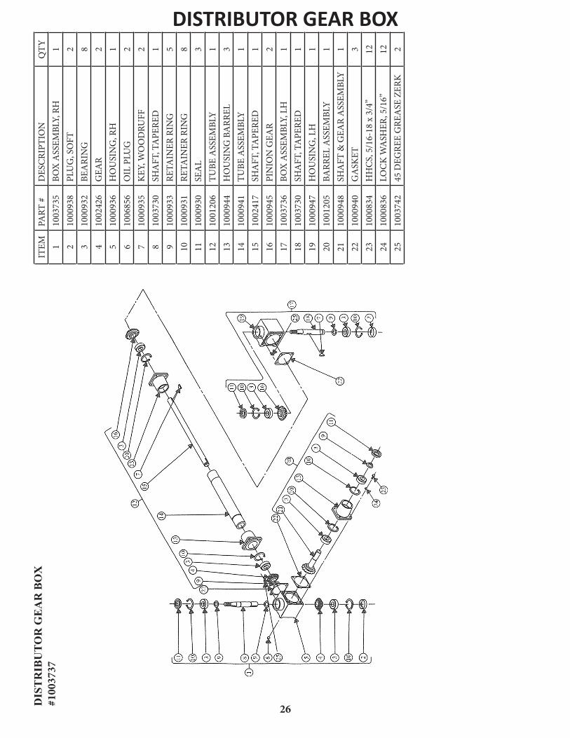
ITEM
PART
#D
ESC
RIPT
ION
QTY
110
0373
5BO
X A
SSEM
BLY,
RH
12
1000
938
PLU
G, S
OFT
23
1000
932
BEA
RIN
G8
410
0242
6G
EAR
25
1000
936
HO
USI
NG
, RH
16
1006
856
OIL
PLU
G2
710
0093
5K
EY, W
OO
DRU
FF2
810
0373
0SH
AFT
, TA
PERE
D1
910
0093
3RE
TAIN
ER R
ING
510
1000
931
RETA
INER
RIN
G8
1110
0093
0SE
AL
312
1001
206
TUBE
ASS
EMBL
Y1
1310
0094
4H
OU
SIN
G B
ARR
EL3
1410
0094
1TU
BE A
SSEM
BLY
115
1002
417
SHA
FT, T
APE
RED
116
1000
945
PIN
ION
GEA
R2
1710
0373
6BO
X A
SSEM
BLY,
LH
118
1003
730
SHA
FT, T
APE
RED
119
1000
947
HO
USI
NG
, LH
120
1001
205
BARR
EL A
SSEM
BLY
121
1000
948
SHA
FT &
GEA
R A
SSEM
BLY
122
1000
940
GA
SKET
323
1000
834
HH
CS,
5/1
6-18
x 3
/4”
1224
1000
836
LOC
K W
ASH
ER, 5
/16”
1225
1003
742
45 D
EGRE
E G
REA
SE Z
ERK
2
DIS
TR
IBU
TOR
GE
AR
BO
X
#100
3737
DISTRIBUTOR GEAR BOX
1008
463
CO
UPLI
NG
, HA
LF, 1
BR
1008
464
CO
UPLI
NG
, CHA
IN, #
60
1008
462
CO
UPLI
NG
, HA
LF, .
625
BR10
0845
9 BR
AC
KET,
MO
TOR
MO
UNT
MS
1008
458
DOUB
LE S
PIN
NER
MO
TOR
MO
UNT
1008
758
HYDR
AUL
IC M
OTO
R
1003
737
GEA
R BO
X SE
T
60-I-
SS #
60 S
S C
ON
NEC
TING
LIN
K
6416
53 K
EY, .
25 x
.25
x 1.
25
1500
05 N
UT, .
375
NC
, PLT
D15
0209
LO
CK
WA
SHER
, .37
5, P
LTD
1502
12 F
LAT W
ASH
ER, .
375
PLTD
1502
02 L
OC
K W
ASH
ER, .
25 P
LTD
1514
07 B
OLT
, .25
NC
x .7
5 PL
TD
1502
12 F
LAT W
ASH
ER, .
375
PLTD
1502
09 L
OC
K W
ASH
ER, .
375,
PLT
D15
0005
NUT
, .37
5 N
C, P
LTD
1502
12 F
LAT W
ASH
ER, .
375
PLTD
1518
06 B
OLT
, .37
5 N
C x
1.5
, G5,
PLT
D
1518
05 B
OLT
, .37
5 N
C x
1.2
5, P
LTD
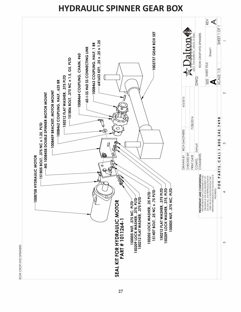
SEA
L KI
T FO
R HY
DRA
ULIC
MO
TOR
PART
# 1
0112
64-1
ROW
CRO
P HY
D S
PIN
NER
S
SHEE
T 1 O
F 1
4/3/
2013
7/28
/201
4D
efau
lt
SCA
LE: 1
:5
REV
SHEE
T TIT
LE:
ASIZE
DW
G:
CO
MM
ENTS
:
PRIN
T D
ATE
CO
NFI
G.
DRA
WN
BY
PRO
PRIE
TARY
AN
D C
ON
FIDE
NTIA
LTH
E IN
FORM
ATIO
N C
ON
TAIN
ED IN
THI
S D
RAW
ING
IS T
HE S
OLE
PRO
PERT
Y O
F D
ALT
ON
AG
. AN
Y RE
PRO
DUC
TION
IN
PART
OR
AS
A W
HOLE
WITH
OUT
THE
W
RITT
EN P
ERM
ISSI
ON
OF
DA
LTO
N A
G IS
PR
OHI
BITE
D.
54
32
1
RIC
H SM
OTH
ERS
A
602
E. V
AN
BUR
EN S
T., L
ENO
X, IA
508
51
Shee
t1
CHE
CKE
D B
Y
F O
R
P A
R T
S ,
C A
L L
1 . 8
0 0
. 3
4 2
. 7 4
9 8
ROW
CRO
P HY
D S
PIN
NER
S
HYDRAULIC SPINNER GEAR BOX
27
B
A
FRO
M T
RAC
TOR
RETU
RN T
O
TRA
CTO
R
CLO
SED
CEN
TER
OPE
N C
ENTE
R
POW
ER5
4
3
11
1
7
10
6
1112
23
3
2
5
7
8
9
9
9
9
4
1008
758
HYD
RAUL
IC M
OTO
R
12
13
13
5
5
FAC
TORY
SET
TO
750
RPM
DO N
OT A
DJUS
T
TRA
CTO
R HY
DRA
ULIC
DRI
VEN
SPI
NN
ERS,
RO
W
CRO
P
SHEE
T 1
OF
2
9/2/
2009
7/28
/201
4D
efau
lt
SCA
LE: 1
:4
REV
SHEE
T TIT
LE:
ASIZE
DW
G:
CO
MM
ENTS
:
PRIN
T D
ATE
CO
NFI
G.
DRA
WN
BY
PRO
PRIE
TARY
AN
D C
ON
FIDE
NTIA
LTH
E IN
FORM
ATIO
N C
ON
TAIN
ED IN
THI
S D
RAW
ING
IS T
HE S
OLE
PRO
PERT
Y O
F D
ALT
ON
AG
. AN
Y RE
PRO
DUC
TION
IN
PART
OR
AS
A W
HOLE
WITH
OUT
THE
W
RITT
EN P
ERM
ISSI
ON
OF
DA
LTO
N A
G IS
PR
OHI
BITE
D.
54
32
1
RIC
H SM
OTH
ERS
A
602
E. V
AN
BUR
EN S
T., L
ENO
X, IA
508
51
SCHE
MA
TIC
CHE
CKE
D B
Y
F O
R
P A
R T
S ,
C A
L L
1 . 8
0 0
. 3
4 2
. 7 4
9 8
TRA
CTO
R HY
DRA
ULIC
DRI
VEN
SPI
NN
ERS,
RO
W C
ROP
28
TRACTOR HYDRAULIC DRIVEN SPINNERS - ROW CROP
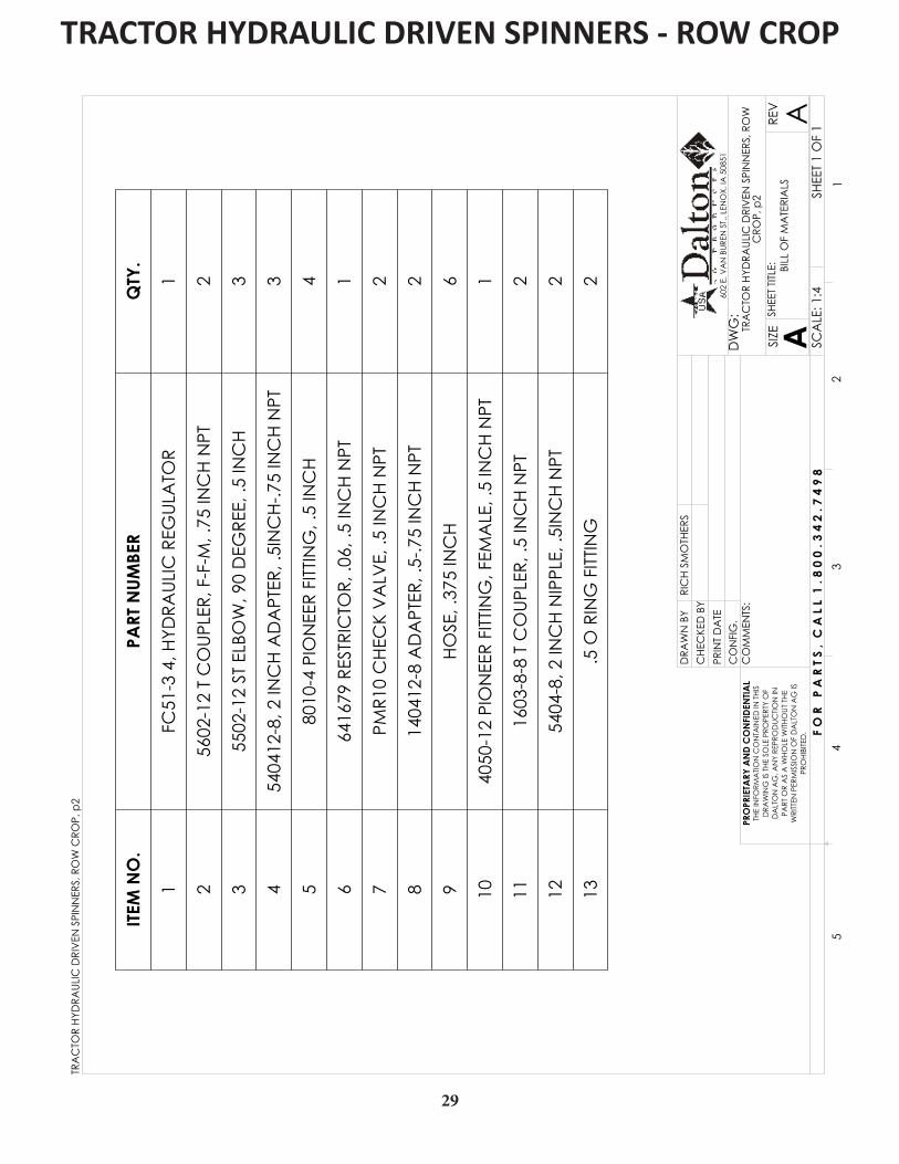
ITEM
NO
.PA
RT N
UMBE
RQ
TY.
1FC
51-3
4, H
YDRA
ULIC
REG
ULA
TOR
1
256
02-1
2 T
CO
UPLE
R, F
-F-M
, .75
INC
H N
PT2
355
02-1
2 ST
ELB
OW
, 90
DEG
REE,
.5 IN
CH
3
454
0412
-8, 2
INC
H A
DA
PTER
, .5I
NC
H-.7
5 IN
CH
NPT
3
580
10-4
PIO
NEE
R FI
TTIN
G, .
5 IN
CH
4
664
1679
RES
TRIC
TOR,
.06,
.5 IN
CH
NPT
1
7PM
R10
CHE
CK
VA
LVE,
.5 IN
CH
NPT
2
814
0412
-8 A
DA
PTER
, .5-
.75
INC
H N
PT2
9HO
SE, .
375
INC
H6
1040
50-1
2 PI
ON
EER
FITT
ING
, FEM
ALE
, .5
INC
H N
PT1
1116
03-8
-8 T
CO
UPLE
R, .5
INC
H N
PT2
1254
04-8
, 2 IN
CH
NIP
PLE,
.5IN
CH
NPT
2
13.5
O R
ING
FITT
ING
2
TRA
CTO
R HY
DRA
ULIC
DRI
VEN
SPI
NN
ERS,
RO
W
CRO
P, p
2 SHEE
T 1 O
F 1
SCA
LE: 1
:4
REV
SHEE
T TIT
LE:
ASIZE
DW
G:
CO
MM
ENTS
:
PRIN
T D
ATE
CO
NFI
G.
DRA
WN
BY
PRO
PRIE
TARY
AN
D C
ON
FIDE
NTIA
LTH
E IN
FORM
ATIO
N C
ON
TAIN
ED IN
THI
S D
RAW
ING
IS T
HE S
OLE
PRO
PERT
Y O
F D
ALT
ON
AG
. AN
Y RE
PRO
DUC
TION
IN
PART
OR
AS
A W
HOLE
WITH
OUT
THE
W
RITT
EN P
ERM
ISSI
ON
OF
DA
LTO
N A
G IS
PR
OHI
BITE
D.
54
32
1
RIC
H SM
OTH
ERS
A
602
E. V
AN
BUR
EN S
T., L
ENO
X, IA
508
51
BILL
OF
MA
TERI
ALS
CHE
CKE
D B
Y
F O
R
P A
R T
S ,
C A
L L
1 . 8
0 0
. 3
4 2
. 7 4
9 8
TRA
CTO
R HY
DRA
ULIC
DRI
VEN
SPI
NN
ERS,
RO
W C
ROP,
p2
29
TRACTOR HYDRAULIC DRIVEN SPINNERS - ROW CROP

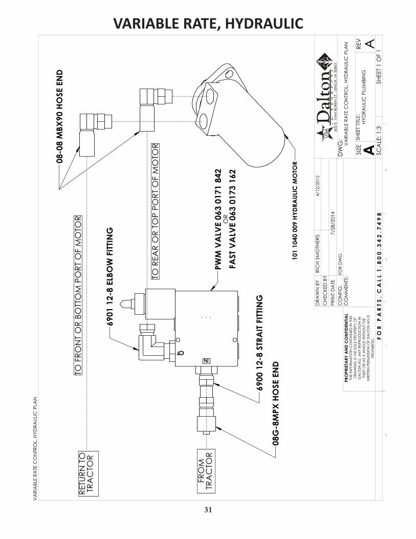
VARIABLE RATE CONTROL, ELECTRICAL PLAN
30
RETU
RN T
O
TRA
CTO
RTO
FRO
NT
OR
BOTT
OM
PO
RT O
F M
OTO
R
TO R
EAR
OR
TOP
PORT
OF
MO
TOR
FRO
M
TRA
CTO
RPW
M V
ALV
E 06
3 01
71 8
42
6900
12-
8 ST
RAIT
FIT
TIN
G
6901
12-
8 EL
BOW
FIT
TIN
G
OR
FAST
VA
LVE
063
0173
162
08G
-8M
PX H
OSE
EN
D
101
1040
009
HYD
RAUL
IC M
OTO
R08-0
8 M
BX90
HO
SE E
ND
VA
RIA
BLE
RATE
CO
NTR
OL,
HYD
RAUL
IC P
LAN
SHEE
T 1
OF
1
4/12
/201
2
7/28
/201
4FO
R D
WG
SCA
LE: 1
:3
REV
SHEE
T TIT
LE:
ASIZE
DW
G:
CO
MM
ENTS
:
PRIN
T D
ATE
CO
NFI
G.
DRA
WN
BY
PRO
PRIE
TARY
AN
D C
ON
FIDE
NTIA
LTH
E IN
FORM
ATIO
N C
ON
TAIN
ED IN
THI
S D
RAW
ING
IS T
HE
SOLE
PRO
PERT
Y O
F D
ALT
ON
AG
. AN
Y RE
PRO
DUC
TION
IN
PART
OR
AS
A W
HO
LE W
ITHO
UT T
HE
WRI
TTEN
PER
MIS
SIO
N O
F D
ALT
ON
AG
IS
PRO
HIBI
TED
.
54
32
1
RIC
H S
MO
THER
S
A
602
E. V
AN
BUR
EN S
T., L
ENO
X, IA
508
51
HYD
RAUL
IC P
LUM
BIN
G
CH
ECKE
D B
Y
F O
R
P A
R T
S ,
C A
L L
1 .
8 0
0 . 3
4 2
. 7
4 9
8
VA
RIA
BLE
RATE
CO
NTR
OL,
HYD
RAUL
IC P
LAN
VARIABLE RATE, HYDRAULIC
31
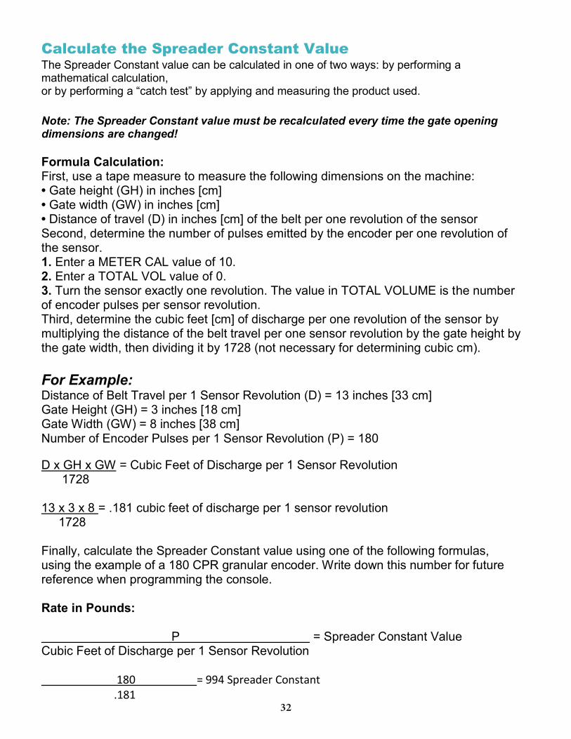
Calculate the Spreader Constant Value The Spreader Constant value can be calculated in one of two ways: by performing a mathematical calculation, or by performing a “catch test” by applying and measuring the product used. Note: The Spreader Constant value must be recalculated every time the gate opening dimensions are changed! Formula Calculation: First, use a tape measure to measure the following dimensions on the machine: • Gate height (GH) in inches [cm] • Gate width (GW) in inches [cm] • Distance of travel (D) in inches [cm] of the belt per one revolution of the sensor Second, determine the number of pulses emitted by the encoder per one revolution of the sensor. 1. Enter a METER CAL value of 10. 2. Enter a TOTAL VOL value of 0. 3. Turn the sensor exactly one revolution. The value in TOTAL VOLUME is the number of encoder pulses per sensor revolution. Third, determine the cubic feet [cm] of discharge per one revolution of the sensor by multiplying the distance of the belt travel per one sensor revolution by the gate height by the gate width, then dividing it by 1728 (not necessary for determining cubic cm). For Example: Distance of Belt Travel per 1 Sensor Revolution (D) = 13 inches [33 cm] Gate Height (GH) = 3 inches [18 cm] Gate Width (GW) = 8 inches [38 cm] Number of Encoder Pulses per 1 Sensor Revolution (P) = 180
D x GH x GW = Cubic Feet of Discharge per 1 Sensor Revolution 1728 13 x 3 x 8 = .181 cubic feet of discharge per 1 sensor revolution 1728 Finally, calculate the Spreader Constant value using one of the following formulas, using the example of a 180 CPR granular encoder. Write down this number for future reference when programming the console. Rate in Pounds: P = Spreader Constant Value Cubic Feet of Discharge per 1 Sensor Revolution 180 = 994 Spreader Constant .181
32

33
CALIBRATION NUMBERS FOR VARIABLE RATE READY SPREADERS
• Inches of belt travel per revolution of rear roller = 13”• Encoder pulses per revolution of rear roller = 180• Gate Width = 8”• Gate Height = Actual inches above the floor (chain is 1/2” thick)• Meter Cal = Product Density• Speed Cal w/Sky Track = 600• Speed Cal w/ Astroll = 783
SPREADER CONSTANT #’S
2.5” Gate Height = 1196 3” Gate Height = 994 3.5” Gate Height = 857 4” Gate Height = 747 4.5” Gate Height = 664 5” Gate Height = 600
The spreader constant is entered by holding dow the meter calibration button until the spreader constant menu comes available.
These numbers are a good starting point and may be adjusted slightly if
your actual rate is off.
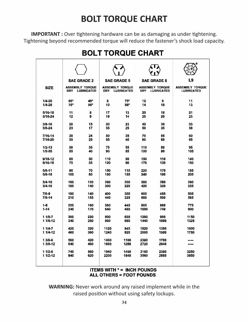
IMPORTANT : Over tightening hardware can be as damaging as under tightening.Tightening beyond recommended torque will reduce the fastener’s shock load capacity.
WARNING: Never work around any raised implement while in the raised position without using safety lockups.
BOLT TORQUE CHART
34

32
DaltonAg.com 800.342.7498602 E. Van Buren Lenox, Iowa 50851100% Employee Owned
PARTS ORDERING PROCEDURE
Your Dalton Ag dealer is interested in your new fertilizer application equipment and has the desire to help you get the most value from it. Through the help of this manual, you will find you can do some of the regular maintenance yourself. For parts and service, contact the Dalton Ag Dealership from which you purchased your fertilizer application equipment or your local Dalton Ag dealer.
When replacement parts are required, consult the applicable illustration and parts list to obtain the correct part name and number. When requesting a replacement part, always include the following information:
1. Complete Part Number 2. Part Name 3. Quantity Required 4. Machine and Model Number 5. Machine Serial Number - located on the topside of the frame near hitch 6. Provide complete name and address for where and how parts are to be shipped.
NOTE: Right and left hand parts and sides of the units are determined by standing at the rear and facing in the direction of forward travel.
EQUIPMENT MODEL:___________________________________
EQUIPMENT SERIAL NO.:________________________________
DATE OF PURCHASE:___________________________________
NAME OF DEALER:_____________________________________
DEALER’S PHONE NUMBER:______________________________
Thank you for your business!
DaltonAg.com 800.342.7498602 E. Van Buren Lenox, Iowa 50851100% Employee Owned
LIMITED WARRANTY
Dalton Ag, Inc. warrants all products, including all equipment and accessories, manufactured by Dalton Ag, Inc. to be free from defects in material and workmanship if the product is operated and serviced according to the manufacturer’s instruction manual. This warranty shall remain effective for twelve months from the date of delivery to the original purchaser.
Dalton Ag, Inc. obligation under this warranty is limited to the repair of replacement of parts (not including labor) which have been returned to Dalton Ag, Inc.factory freight prepaid, and after inspection, are deemed by Dalton Ag, Inc. to be defective. In no event shall Dalton Ag, Inc. be liable for special consequential damages except as may be approved by Dalton Ag, Inc. in advance in writing. This warranty shall not apply to compo-nent parts which are not manufactured by Dalton Ag, Inc. Neither shall this warranty apply to any parts or componenets which are expendable and are expected to wear out in normal service during the course of this warranty.
The provisions of this warranty shall not apply to any Dalton Ag, Inc. product which has been subject to mis-use, negligence, alteration, or accident, or which shall have been repaired in any way so as, in the reasonable judgement of Dalton Ag, Inc. to affect adversely its performance and reliability.
This warranty is expressly in lieu of all other warranties, expressed or implied, including any implied warranty of merchantability or fitness for a particular purpose, and of any other obligations for liability on the part of Dalton Ag, Inc. and Dalton Ag, Inc. neither assumes nor authroizes any other person to assume ofr it any other liability in connection with such products.
COMPANY POLICY
1. Specify catalog numbers, sizes, and all other information necessary to properly fill the order.2. Check merchandise immediately upon receipt. If received in bad condition or there is a shortage of bundles or boxes, do not fail to note this fact on the carrier promptly. Shortages must be reported within fifteen days of receiving the product.3. Returned goods will not be accepted without our consent. All returned merchandise is subject to 10% re-stocking charge.4. Good returned for credit must be prepaid and accompanied by Dalton Ag, Inc. bill of lading letter of expla-nation giving order numbers, invoice number, date purchased and reason for returning merchandise. If error is made by Dalton Ag, Inc., we will accept merchandise freight collect if returned by lowest transportation cost. Goods must be returned within 60 days after purchase.5. Our warranty does not cover the use of chemicals harmful to equipment of the operator. It does cover de-fective material or workmanship, and is limited to value of material only. 6. Cutting or welding on merchandise without our approval voids the warranty.7. Special orders require deposits and are not subject to cancellation without our consent.
36


www.DaltonAg.com602 E. VAN BUREN LENOX, IOWA 50851 800.342.7498