Operating and mounting instructions - Dungs · PDF fileRead the operating and mounting...
114
Printed in Germany / M-BOS • Edition 03.14 • Nr. 231 763 1 … 114 Read the operating and mounting instructions be- fore commissioning. Only specialised personnel may perform work on the auto- matic burner control system. Never perform any work when the control system is live. This also applies if low- voltage components such as servomotors, display or com- munication components are replaced or installed. In case of fuse failure, check the safety function of the automatic burner control system. Otherwise contact weld caused by short-circuit may oc- cur. Only specialised personnel may set operating param- eters. Only use the communica- tion connection together with components expressly ap- proved for this purpose. Perform the connection related to the correct phase and the protective conductor con- nection according to the terminal diagram and check it before com- missioning. Warranty for the control system expires on improper handling of the electronic system or due to incorrect storage. The data contained in these instructions specify the automatic burner control system. They do not imply any characteristics. If you do not follow these instructions, danger to life to the equipment may occur. Technical description The MPA22 is a microprocessor-con- trolled, automatic burner control system with intermittent duty for controlling and monitoring two- and three stage modu- lating blower burners with a single ser- vomotor, electronic modulating blower burners with 2 servomotors in combina- tion with an electronic control unit, and pneumatic modulating blower burners with 1 servomotor.With integrated valve proving system for operation as auto- matic gas burner control system. The MPA22 has an eBUS connection. Operating and mounting instructions Automatic burner control system MPA22 Accessories Flame monitoring device Servomotors Display unit eBUS interface Coding plug Connector plug Classification according to EN 298 FMCLJN, depending on programming FMLLJN, depending on programming Approvals for gas types EU type test approval as per EU Gas Appliance Directive. MPA22 CE-0085AU316 Approvals for oil types Register/type test number MPA22 5F185/99
Transcript of Operating and mounting instructions - Dungs · PDF fileRead the operating and mounting...
Prin
ted
in G
erm
any
/ M-B
OS
• Edi
tion
03.1
4 • N
r. 23
1 76
3
1 … 114
Read the operating and mounting instructions be-
fore commissioning.
Only specialised personnel may perform work on the auto-
matic burner control system.
Never perform any work when the control system
is live. This also applies if low-voltage components such as servomotors, display or com-munication components are replaced or installed.
In case of fuse failure, check the safety function
of the automatic burner control system. Otherwise contact weld caused by short-circuit may oc-cur.
Only specialised personnel may set operating param-
eters.
Only use the communica-tion connection together
with components expressly ap-proved for this purpose.
Perform the connection related to the correct phase
and the protective conductor con-nection according to the terminal diagram and check it before com-missioning.
Warranty for the control system expires on improper
handling of the electronic system or due to incorrect storage.
The data contained in these instructions specify
the automatic burner control system. They do not imply any characteristics.
If you do not follow these instructions, danger to life
to the equipment may occur.
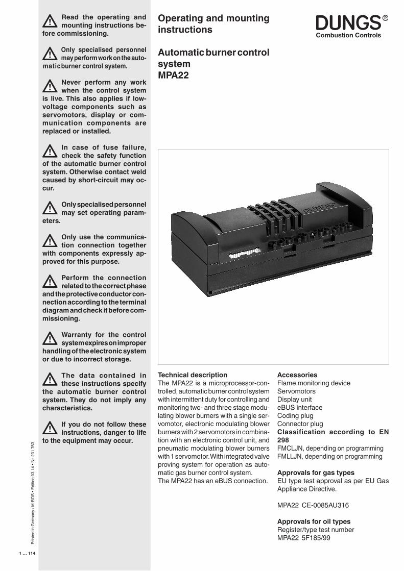
Technical descriptionThe MPA22 is a microprocessor-con-trolled, automatic burner control system with intermittent duty for controlling and monitoring two- and three stage modu-lating blower burners with a single ser-vomotor, electronic modulating blower burners with 2 servomotors in combina-tion with an electronic control unit, and pneumatic modulating blower burners with 1 servomotor. With integrated valve proving system for operation as auto-matic gas burner control system.The MPA22 has an eBUS connection.
Operating and mounting instructions
Automatic burner control system MPA22
AccessoriesFlame monitoring deviceServomotorsDisplay uniteBUS interfaceCoding plugConnector plugClassification according to EN 298FMCLJN, depending on programmingFMLLJN, depending on programming
Approvals for gas typesEU type test approval as per EU Gas Appliance Directive.
MPA22 CE-0085AU316
Approvals for oil typesRegister/type test numberMPA22 5F185/99
Prin
ted
in G
erm
any
/ M-B
OS
• Edi
tion
03.1
4 • N
r. 23
1 76
3
2 … 114
Contents
Specifications...........................................................................................................................................................3-11Operating modes.........................................................................................................................................................12Operating modes Gas firing, electronic modulation ...............................................................................................13-14Terminal diagram - Gas firing, electronic modulation...................................................................................................15Operating mode Gas firing, pneumatic modulation.................................................................................................16-17Terminal diagram - Gas firing, pneumatic modulation..................................................................................................18Operating mode - Oil firing, three stage..................................................................................................................19-20Terminal diagram - Oil firing, three stage......................................................................................................................21Integrated valve proving system, gas firing.............................................................................................................22-25Time diagram - Gas firing, electronic modulation....................................................................................................26-27Time diagram - Gas firing, pneumatic modulation...................................................................................................28-29Time diagram - Oil firing, three stage......................................................................................................................30-31Explanation display......................................................................................................................................................32Display functions..........................................................................................................................................................33Relationships between the individual display modes..............................................................................................34-35Display during standby.................................................................................................................................................36Display when a password is entered in parameterisation or setup mode.....................................................................37Display when the basic configuration is entered.....................................................................................................38-39Commissioning, setup mode.......................................................................................................................................40Commissioning Main parameters................................................................................................................................41Setup mode - Gas firing, electronic modulation......................................................................................................42-51Setup mode - Gas firing, pneumatic modulation.....................................................................................................52-56Setup mode - Oil firing, three stage.........................................................................................................................57-63Display in operating mode Gas firing, electronic modulation and Gas firing, pneumatic modulation..............................................................64-69Display in operating mode „Oil firing, three stage“..................................................................................................70-74Display in information mode Gas firing, electronic modulation; Gas firing, pneumatic modulation; Oil firing, three stage................................75-78Display in service mode Gas firing, electronic modulation...........................................................................................................................79-87Display in service mode; Gas firing, pneumatic modulation..................................................................................88-93Display in service mode; Oil firing, three stage.....................................................................................................94-99Display in parameterisation mode Gas firing, electronic modulation; Gas firing pneumatic modulation; Oil firing, three stage.............................100-108Error indicationGas firing, electronic modulation; Gas firing, pneumatic modulation; Oil firing, three stage ...............................109-110Error messages..................................................................................................................................................111-113Notes.........................................................................................................................................................................114
Prin
ted
in G
erm
any
/ M-B
OS
• Edi
tion
03.1
4 • N
r. 23
1 76
3
3 … 114
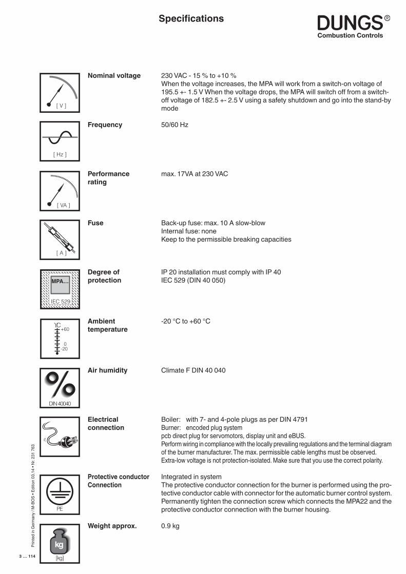
Nominal voltage 230 VAC - 15 % to +10 % When the voltage increases, the MPA will work from a switch-on voltage of
195.5 +- 1.5 V When the voltage drops, the MPA will switch off from a switch-off voltage of 182.5 +- 2.5 V using a safety shutdown and go into the stand-by mode
Frequency 50/60 Hz
Performance max. 17VA at 230 VACrating
Fuse Back-up fuse: max. 10 A slow-blow Internal fuse: none Keep to the permissible breaking capacities
Degree of IP 20 installation must comply with IP 40protection IEC 529 (DIN 40 050)
Ambient -20 °C to +60 °Ctemperature
Air humidity Climate F DIN 40 040
Electrical Boiler: with 7- and 4-pole plugs as per DIN 4791connection Burner: encoded plug system pcb direct plug for servomotors, display unit and eBUS. Perform wiring in compliance with the locally prevailing regulations and the terminal diagram
of the burner manufacturer. The max. permissible cable lengths must be observed. Extra-low voltage is not protection-isolated. Make sure that you use the correct polarity.
Protective conductor Integrated in systemConnection The protective conductor connection for the burner is performed using the pro-
tective conductor cable with connector for the automatic burner control system. Permanently tighten the connection screw which connects the MPA22 and the protective conductor connection with the burner housing.
Weight approx. 0.9 kg
[ Hz ]
[ V ]
[ A ]
IEC 529IEC 529
MPA…
ϒC
0
+60
-20
DIN 40040
PE
[kg]
kg
Specifications
[ VA ]
Prin
ted
in G
erm
any
/ M-B
OS
• Edi
tion
03.1
4 • N
r. 23
1 76
3
4 … 114
Flame supervision
Servomotors
Display module
Minimum display
Coding plug oil three stage
Coding plug gas pneumatic
Fault unlock
Pulse counter input
Breaking capacitiesTotal max. 10 A
Designation Breaking capacityBurner motor 230 VAC/4 A/cos ϕ = 1 230 VAC/1,5 A/cos ϕ = 0,4Burner motor (endurance run) 230 VAC/4 A/cos ϕ = 1 230 VAC/1,5 A/cos ϕ = 0,4Ignition transformer 230 VAC/3 A/cos ϕ = 1 230 VAC/1 A/cos ϕ = 0,2Valve Y1 + status display 230 VAC/2 A/cos ϕ = 0,4Valve Y2 230 VAC/2 A/cos ϕ = 0,4Valve Y3 230 VAC/2 A/cos ϕ = 0,4Fault output 230 VAC/1 A/cos ϕ = 0,4Safety sequence (pressure switch max. gas) 230 VAC/10 APulse generator 24 VDC/2 mAPressure switch air stage 24 VDC/20 mAPressure switch min. gas 24 VDC/20 mAPressure switch VPS 24 VDC/20 mAFlame detector Ionisation electrode 230 VAC UV diode 230 VAC Photoresistor 5 VDC Servomotor gas 24 VDC/max.300 mAServomotor air 24 VDC/max.300 mADisplay board 24 VDC/max.10 mABus interface 5 VDC/10 mATemperature or pressure regulator 230 VAC/10 mANegative capacity or stage 2 230 VAC/10 mAPositive capacity or stage 3 230 VAC/10 mA
Specifications
IonisationUV diode: UV4 (Dungs)Infrared/UV: IRD 1020 ov. IRD 1020.1 or UVD 971 (Satronic) KLC 1000, 1001 or 2002 (BST Solution) FLW10, FLW20 (DUNGS) Please note that the reaction times of the MPA 22 (< 1 s) and of the sensors (< 1 s; see corresponding data) will add up!only for oil burnersPhotoresistor: QRM 1A (Landis & Stefa)Photoresistor: MZ 770 (Satronic)
Stepped-motor servomotor with integrated stepped motor driver and digital acknowledgement via encoder diskSAD 1.2 with 1.2 Nm torque (IP 40)SAD 1.2 WG with 1.2 Nm torque (IP 54)SAD 1.5 with 1.5 Nm torque (IP 40)SAD 1.5 / Pot. 10k with 1.5 Nm torque (IP 40)SAD 3.0 with 3 Nm torque (IP 40)SAD 3.0 WG with 3 Nm torque (IP 54)
Display module AM01 with 7 1/2-digit LCD display and 5 operating keys incl. unlocking key. Connected via a 6-pole cable, cable length: max. 1 m
Unlocking key with fault indicator lamp instead of display unit
Coding plug CS01 for operation as oil burner instead of the servomotor gas
Coding plug CS02 for operation as gas burner in combination with pneumatic system instead of the servomotor gas
Via the unlocking key on the AM xx Display or via a separate unlocking key
Connection possibility for a floating pulse counter contact for fuel volume ac-quisition, adjustable divisor in EEPROM. Max. 255 pulses/unit of volume, max. 6 Hz
Prin
ted
in G
erm
any
/ M-B
OS
• Edi
tion
03.1
4 • N
r. 23
1 76
3
5 … 114
The MPA22 is an eBUS compatible device. Depending on the ap-plication, various interfaces are used for connections. Connections to the eBUS is only permissible using an MPA/eBUS interface or an
MPA/PC interface. The interfaces must be electrically isolated (VDE 0551).
The MPA22 software supports the eBUS protocol in accordance with the eBUS specifications V1.2 at the connection layer OSI 2, the V1.3 application layer OSI 2, and the V1.4 application layer OSI 7.
The following communication commands are implemented for MPA controller communications to the eBUS specification:
Service data commands (Service 03h 04h to 08h)Burner control commands (Service 05h 00h to 03h, 08h, 09hSystem data commands (Service 07h 03h to 05h, FEh and FFh)Broadcast message (Service FEh 01h)
The commands listed can make the following MPA22 information available to other eBUS compatible subscribers via the eBUS:
Number of successful start-upsOperating hoursFuel consumptionPeriodic information from an external controller to the MPA22 concerning heat requirements and modulation grade.Periodic information from the MPA22 to an external controller concerning heat requirements and modulation grade.State numberAir pressure monitor operating statusGas pressure monitor operating statusFlame operating statusValve Y2 operating statusValve Y3 operating statusAlarm signalModulation depthDevice numberSoftware versionHardware version
In case of errorMPA identificationError codeExtra error messageState numberSoftware watchdog valueSubroutine entry codeSubroutine exit code
Comunication
Specifications
Prin
ted
in G
erm
any
/ M-B
OS
• Edi
tion
03.1
4 • N
r. 23
1 76
3
6 … 114
MPA-Vision is a software tool to connect the eBUS to the MPA22. This Software tool contains the following options:
Periodic transmission of operating parametersInternal error memory displayParameterising the MPALoad and save complete parameter setsVarious printing options eBUS monitor for checking proper functioning
The automatic burner control system has a default state so that a basic setting is available for the burner manufacturer or in case of replacement.
arbitrary
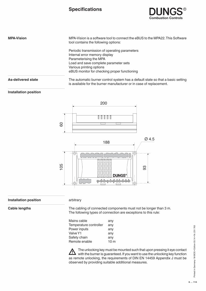
The cabling of connected components must not be longer than 3 m.The following types of connection are exceptions to this rule:
Mains cable anyTemperature controller anyPower inputs anyValve Y1 anySafety chain anyRemote enable 10 m
The unlocking key must be mounted such that upon pressing it eye contact with the burner is guaranteed. If you want to use the unlocking key function
as remote unlocking, the requirements of DIN EN 14459 Appendix J must be observed by providing suitable additional measures.
MPA-Vision
As-delivered state
Installation position
Installation position
Cable lengths
200
188
6010
5
93Ø 4.5
B4S3T2NL1 PET8T7T6B5 T1 T2S3 B4
Specifications
Prin
ted
in G
erm
any
/ M-B
OS
• Edi
tion
03.1
4 • N
r. 23
1 76
3
7 … 114
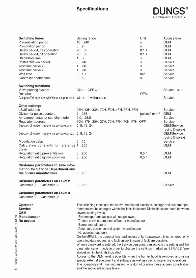
Switching timesPreventilation periodPre-ignition periodSafety period, gas operationSafety period, oil operationStabilising timePostventilation periodTest time, valve Y2Test time, valve Y3Wait timeController enable time
Switching functionsValve proving systemRestartsGas pneu/Oil operation with/without supervision
Other settingseBUS addressDivisor for pulse countersAir damper actuator standby modeRegulator addressDirection of rotation + reference servomotor air
Direction of rotation + reference servomotor gas
Modulation delayCalculating constants for reference curveRegulation ratio pre-ventilationRegulation ratio ignition position
Customer parameters to save infor-mation for Service Department and the burner manufacturer
Customer parameters on Level 2Customer 20…Customer 35
Customer parameters on Level 3Customer 30…Customer 35
OperatorServiceOEMManufacturerNo access
Setting range Unit Access level10…240 s OEM0…2 s OEM20…50 0.1 s OEM20…50 0.1 s OEM1…60 s OEM0…240 s Service1…240 s Service1…240 s Service0…100 min Service0…59 s Service
ON ≥ 1 OFF = 0 Service 0…1 OEMwith ≥ 1 , without = 0 Service
03H, 13H, 33H, 73H, F3H, 1FH, 3FH, 7FH Service1…255 pulses/l or m3 OEM0.0…25.5 ° Service10H, 17H, 30H, 37H, 70H, 77H, F0H, F7H, OFF Service0, 8, 16, 24 OEM/Service (using Display)0, 8, 16, 24 OEM/Service (using Display)0…15 Service1…255 OEM
0…200 0,5 ° OEM0…200 0,5 ° OEM
0…255 OEM
0…255 Service
The switching times and the above-mentioned functions, settings and customer pa-rameters can be changed within the limits indicated. Distinctions are made between several setting levels:- System operator, access without password- Trained service personnel of burner manufacturer- Burner manufacturer- Automatic burner control system manufacturer- No access, read onlyOn the MPA22, the operator has read access only. If a password is not entered, only operating data request and fault unlock in case of fault are possible.When a password is entered, the Service personnel can activate the setting and the parameterisation mode in order to change the settings marked as SERVICE (see above) within the limits indicated.Access to the OEM level is possible when the burner hood is removed and using special external equipment and software as well as specific interactive operations.The operating and mounting instructions do not contain these access possibilities and the subjacent access levels.
Specifications
Prin
ted
in G
erm
any
/ M-B
OS
• Edi
tion
03.1
4 • N
r. 23
1 76
3
8 … 114
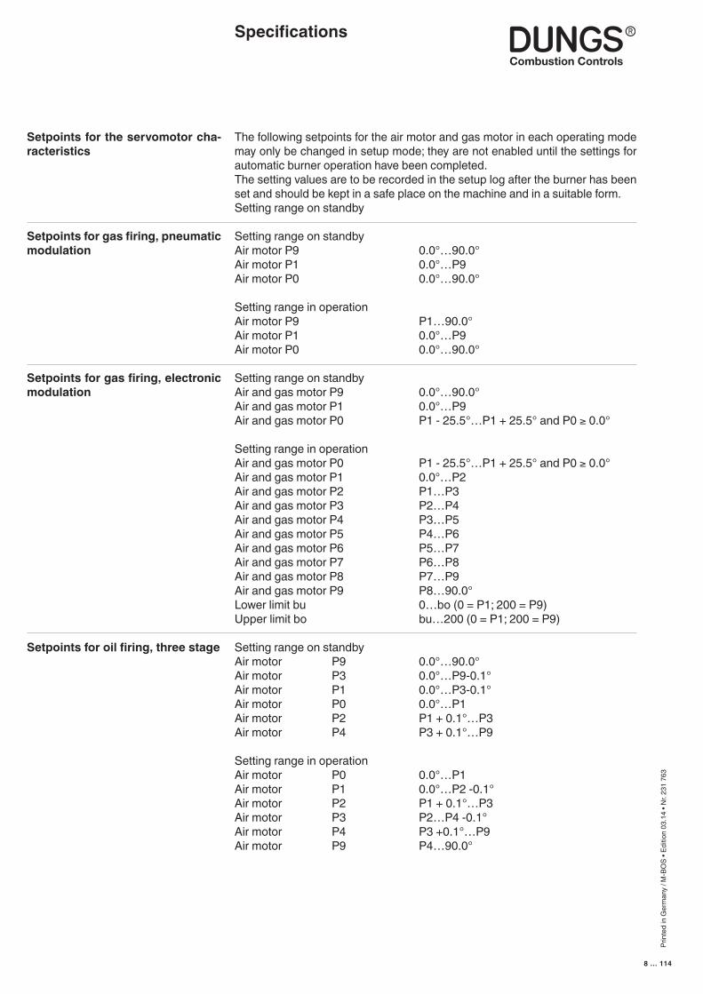
Setpoints for the servomotor cha-racteristics
Setpoints for gas firing, pneumatic modulation
Setpoints for gas firing, electronic modulation
Setpoints for oil firing, three stage
The following setpoints for the air motor and gas motor in each operating mode may only be changed in setup mode; they are not enabled until the settings for automatic burner operation have been completed.The setting values are to be recorded in the setup log after the burner has been set and should be kept in a safe place on the machine and in a suitable form.Setting range on standby
Setting range on standby Air motor P9 0.0°…90.0° Air motor P1 0.0°…P9 Air motor P0 0.0°…90.0° Setting range in operationAir motor P9 P1…90.0°Air motor P1 0.0°…P9Air motor P0 0.0°…90.0°
Setting range on standbyAir and gas motor P9 0.0°…90.0°Air and gas motor P1 0.0°…P9Air and gas motor P0 P1 - 25.5°…P1 + 25.5° and P0 ≥ 0.0°
Setting range in operationAir and gas motor P0 P1 - 25.5°…P1 + 25.5° and P0 ≥ 0.0°Air and gas motor P1 0.0°…P2Air and gas motor P2 P1…P3Air and gas motor P3 P2…P4Air and gas motor P4 P3…P5Air and gas motor P5 P4…P6Air and gas motor P6 P5…P7Air and gas motor P7 P6…P8Air and gas motor P8 P7…P9Air and gas motor P9 P8…90.0°Lower limit bu 0…bo (0 = P1; 200 = P9)Upper limit bo bu…200 (0 = P1; 200 = P9)
Setting range on standbyAir motor P9 0.0°…90.0°Air motor P3 0.0°…P9-0.1°Air motor P1 0.0°…P3-0.1°Air motor P0 0.0°…P1Air motor P2 P1 + 0.1°…P3Air motor P4 P3 + 0.1°…P9
Setting range in operationAir motor P0 0.0°…P1Air motor P1 0.0°…P2 -0.1°Air motor P2 P1 + 0.1°…P3Air motor P3 P2…P4 -0.1°Air motor P4 P3 +0.1°…P9Air motor P9 P4…90.0°
Specifications
Prin
ted
in G
erm
any
/ M-B
OS
• Edi
tion
03.1
4 • N
r. 23
1 76
3
9 … 114
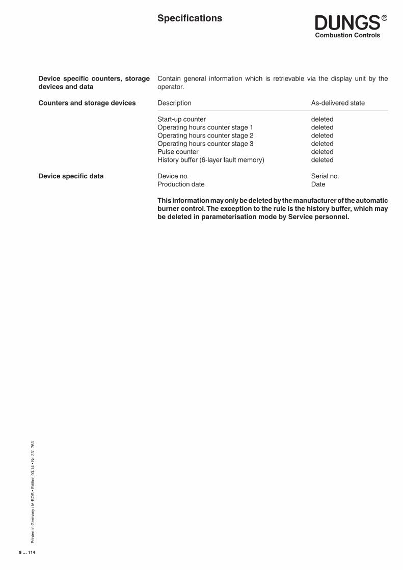
Contain general information which is retrievable via the display unit by the operator.
Description As-delivered state
Start-up counter deletedOperating hours counter stage 1 deletedOperating hours counter stage 2 deletedOperating hours counter stage 3 deletedPulse counter deletedHistory buffer (6-layer fault memory) deleted
Device no. Serial no.Production date Date
This information may only be deleted by the manufacturer of the automatic burner control. The exception to the rule is the history buffer, which may be deleted in parameterisation mode by Service personnel.
Device specific counters, storage devices and data
Counters and storage devices
Device specific data
Specifications
Prin
ted
in G
erm
any
/ M-B
OS
• Edi
tion
03.1
4 • N
r. 23
1 76
3
10 … 114
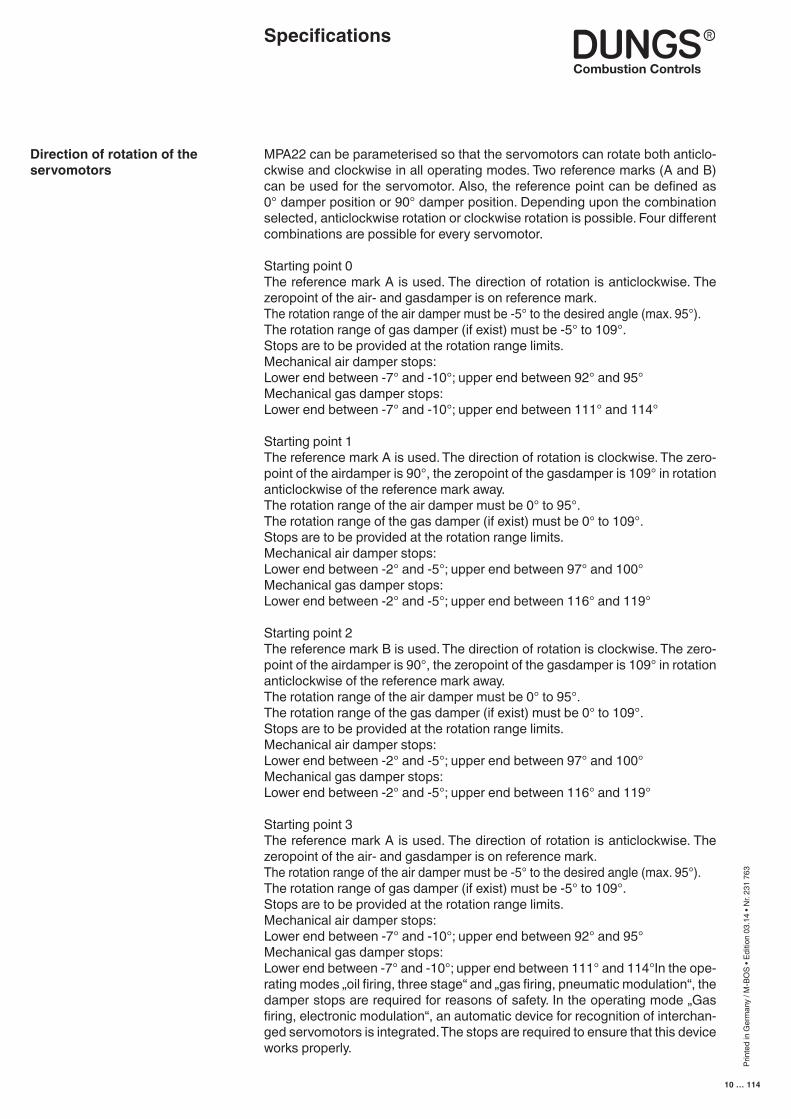
MPA22 can be parameterised so that the servomotors can rotate both anticlo-ckwise and clockwise in all operating modes. Two reference marks (A and B) can be used for the servomotor. Also, the reference point can be defined as 0° damper position or 90° damper position. Depending upon the combination selected, anticlockwise rotation or clockwise rotation is possible. Four different combinations are possible for every servomotor.
Starting point 0The reference mark A is used. The direction of rotation is anticlockwise. The zeropoint of the air- and gasdamper is on reference mark.The rotation range of the air damper must be -5° to the desired angle (max. 95°).The rotation range of gas damper (if exist) must be -5° to 109°.Stops are to be provided at the rotation range limits.Mechanical air damper stops:Lower end between -7° and -10°; upper end between 92° and 95°Mechanical gas damper stops:Lower end between -7° and -10°; upper end between 111° and 114°
Starting point 1The reference mark A is used. The direction of rotation is clockwise. The zero-point of the airdamper is 90°, the zeropoint of the gasdamper is 109° in rotation anticlockwise of the reference mark away.The rotation range of the air damper must be 0° to 95°.The rotation range of the gas damper (if exist) must be 0° to 109°.Stops are to be provided at the rotation range limits.Mechanical air damper stops:Lower end between -2° and -5°; upper end between 97° and 100°Mechanical gas damper stops:Lower end between -2° and -5°; upper end between 116° and 119°
Starting point 2The reference mark B is used. The direction of rotation is clockwise. The zero-point of the airdamper is 90°, the zeropoint of the gasdamper is 109° in rotation anticlockwise of the reference mark away.The rotation range of the air damper must be 0° to 95°.The rotation range of the gas damper (if exist) must be 0° to 109°.Stops are to be provided at the rotation range limits.Mechanical air damper stops:Lower end between -2° and -5°; upper end between 97° and 100°Mechanical gas damper stops:Lower end between -2° and -5°; upper end between 116° and 119°
Starting point 3The reference mark A is used. The direction of rotation is anticlockwise. The zeropoint of the air- and gasdamper is on reference mark.The rotation range of the air damper must be -5° to the desired angle (max. 95°).The rotation range of gas damper (if exist) must be -5° to 109°.Stops are to be provided at the rotation range limits.Mechanical air damper stops:Lower end between -7° and -10°; upper end between 92° and 95°Mechanical gas damper stops:Lower end between -7° and -10°; upper end between 111° and 114°In the ope-rating modes „oil firing, three stage“ and „gas firing, pneumatic modulation“, the damper stops are required for reasons of safety. In the operating mode „Gas firing, electronic modulation“, an automatic device for recognition of interchan-ged servomotors is integrated. The stops are required to ensure that this device works properly.
Direction of rotation of the servomotors
Specifications
Prin
ted
in G
erm
any
/ M-B
OS
• Edi
tion
03.1
4 • N
r. 23
1 76
3
11 … 114
Specifications
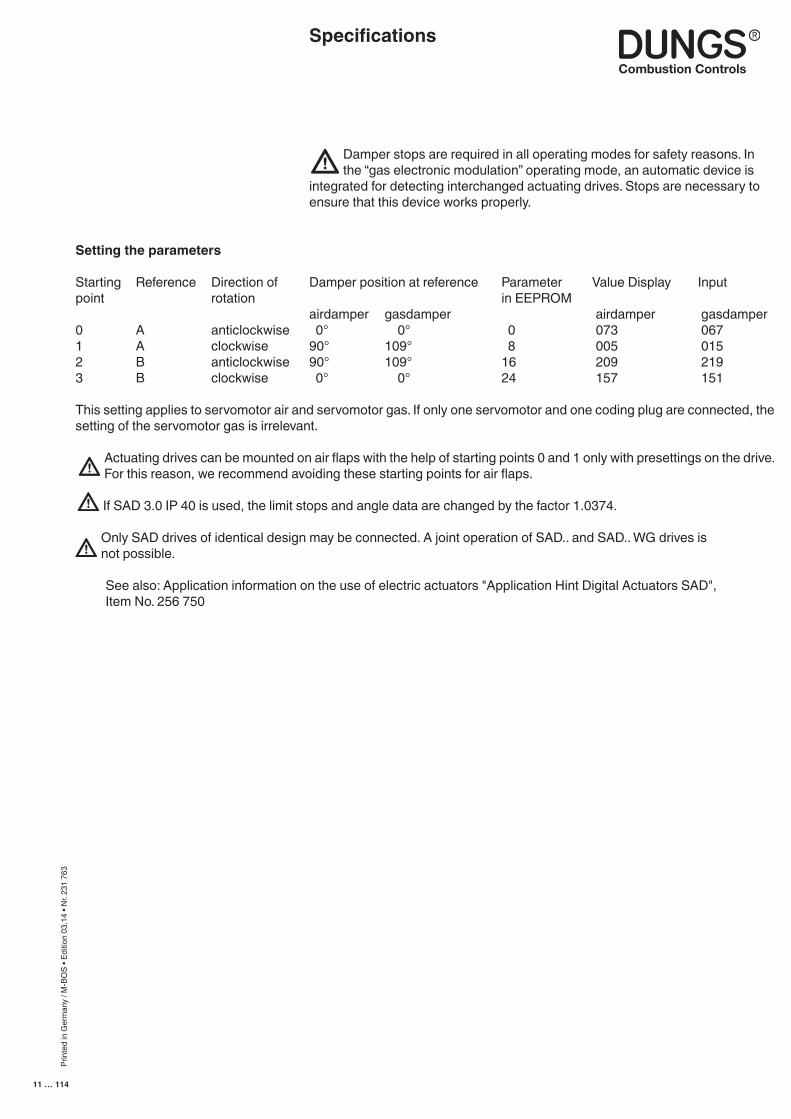
Setting the parameters
Starting Reference Direction of Damper position at reference Parameter Value Display Inputpoint rotation in EEPROM airdamper gasdamper airdamper gasdamper0 A anticlockwise 0° 0° 0 073 067 1 A clockwise 90° 109° 8 005 0152 B anticlockwise 90° 109° 16 209 219 3 B clockwise 0° 0° 24 157 151
This setting applies to servomotor air and servomotor gas. If only one servomotor and one coding plug are connected, the setting of the servomotor gas is irrelevant.
Actuating drives can be mounted on air flaps with the help of starting points 0 and 1 only with presettings on the drive. For this reason, we recommend avoiding these starting points for air flaps.
If SAD 3.0 IP 40 is used, the limit stops and angle data are changed by the factor 1.0374.
Only SAD drives of identical design may be connected. A joint operation of SAD.. and SAD.. WG drives is not possible.
See also: Application information on the use of electric actuators "Application Hint Digital Actuators SAD", Item No. 256 750
Damper stops are required in all operating modes for safety reasons. In the “gas electronic modulation” operating mode, an automatic device is
integrated for detecting interchanged actuating drives. Stops are necessary to ensure that this device works properly.

Prin
ted
in G
erm
any
/ M-B
OS
• Edi
tion
03.1
4 • N
r. 23
1 76
3
12 … 114
Operating modes
■ Operating modes of MPA22
■ Setting the operating mode
Gas modulating mode (electronic) with stepped motor to control the air and gas volume.
Gas modulating mode (pneumatic) with servomotor air damper control
Oil firing, three stage with oil preheater and servomotor air damper control
The operating mode is set at the servomotor gas connection by means of the coding plug and is checked and identified when the automatic burner control is put into operation.

Prin
ted
in G
erm
any
/ M-B
OS
• Edi
tion
03.1
4 • N
r. 23
1 76
3
13 … 114
Servomotor air plugged inServomotor gas plugged in
The internal self-tests are performed when the regulator issues a heating request. First, the servomotor air locates its reference point, then the servomotor gas.The servomotor air then moves to pre-ventilation position P9.The idle position of the air pressure switch is checked and the flame monitoring device is checked for flame simulation. If these checks are successful, the blower is energised.When the air pressure switch is closed, the preset pre-purge period elapses and the remaining pre-purge period is displayed. Pre-purging is monitored by the air pressure switch.During the pre-purge period, the servomotor gas runs to position 109° to check whether the servomotors for gas and air have been interchanged.After the servomotor has reached the 109° position it returns to ignition point P0 during the pre-purge period.If a valve test has still not been performed after a power failure or fault shut-down and the valve proving function has been selected, a valve test and restart are performed once the pre-purge period has expired.
Otherwise, external valve Y1 (liquid gas) of the servomotor air opens and the servomotor air moves to ignition point P0 after the pre-purge period has expired. After the servomotor air has reached ignition point P0, the ignition is turned on for the preset pre-purge period (with pre-ignition period = 2 s).Valve Y2 is opened two seconds before the startup safety period commences (the ignition is also turned on if pre-ignition period = 1s). The gas pressure switch GW_min must indicate the presence of gas pressure within this period of time. Otherwise, a safety shut-down will be triggered and the gas fail-safe program executed. If gas pressure is present after 2 seconds, the ignition is turned on (if pre-ignition period = 0) and valve Y3 is opened.The ignition cuts out at the end of the safety period and, provided that a flame is present, the two servomotors remain in the ignition position for the preset sta-bilising time. After the stabilising time has expired, the servomotors alternately move to position P1 in stepping mode. The burner controller dwells at point P1 for the preset controller enable time. On expiration of the controller enable time, the automatic burner control system is in the operating position.
If the “Lower limit” bu > 0, the automatic burner control operates according to the characteristic curve defined by points P1 to P9, consecutively activating the servomotors until it reaches the predefined minimum capacity point in the closed-loop control mode.The MPA22 is now in closed-loop control mode, i.e. it accepts the control signals applied to the inputs capacity + and capacity - and thus regulates the capacity over the predefined characteristic curve in the range between bu and bo.If the MPA22 has already been in service for 24 hours, a controlled shut-down is executed automatically.If the heating request is cancelled, a controlled shut-down takes place. If the valve proving system is not activated, valves Y2 and Y3 and the external valve Y1 close and the blower runs on for the preset postventilation period.If the valve proving system is activated, a leakage check is performed on gas valves Y2 and Y3. The post-ventilation period elapses in parallel with the leakage check.
When the blower is switched off, the servomotor air runs to the set standby po-sition and then the servomotor gas runs to position 0°.A restart lock-out period (if set) now elapses (the time is indicated on the display), or the automatic burner control enters standby mode (readout on display = OFF).
Operating modeGas firing, electronic modulation
■ Configuration Gas firing, electronic modulation
■ Functional sequence Gas firing, electronic modulation
Prin
ted
in G
erm
any
/ M-B
OS
• Edi
tion
03.1
4 • N
r. 23
1 76
3
14 … 114
Operating modeGas firing, electronic modulation
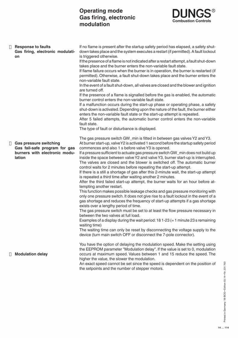
If no flame is present after the startup safety period has elapsed, a safety shut-down takes place and the system executes a restart (if permitted). A fault lockout is triggered otherwise.If the presence of a flame is not indicated after a restart attempt, a fault shut-down takes place and the burner enters the non-variable fault state.If flame failure occurs when the burner is in operation, the burner is restarted (if permitted). Otherwise, a fault shut-down takes place and the burner enters the non-variable fault state.In the event of a fault shut-down, all valves are closed and the blower and ignition are turned off.If the presence of a flame is signalled before the gas is enabled, the automatic burner control enters the non-variable fault state.If a malfunction occurs during the start-up phase or operating phase, a safety shut-down is activated. Depending upon the nature of the fault, the burner either enters the non-variable fault state or the start-up attempt is repeated.After 5 failed attempts, the automatic burner control enters the non-variable fault state.The type of fault or disturbance is displayed.
The gas pressure switch GW_min is fitted in between gas valves Y2 and Y3.At burner start-up, valve Y2 is activated 1 second before the startup safety period commences and also 1 s before valve Y3 is opened.If a pressure sufficient to actuate gas pressure switch GW_min does not build up inside the space between valve Y2 and valve Y3, burner start-up is interrupted. The valves are closed and the blower is switched off. The automatic burner control waits for 2 minutes before repeating the start-up attempt.If there is a still a shortage of gas after this 2-minute wait, the start-up attempt is repeated a third time after waiting another 2 minutes.After the third failed start-up attempt, the burner waits for an hour before at-tempting another restart.This function makes possible leakage checks and gas pressure monitoring with only one pressure switch. It does not give rise to a fault lockout in the event of a gas shortage and reduces the frequency of start-up attempts if a gas shortage exists over a lengthy period of time.The gas pressure switch must be set to at least the flow pressure necessary in between the two valves at full load.Examples of a display during the wait period: 18 1-23 (= 1 minute 23 s remaining waiting time)The waiting time can only be reset by disconnecting the voltage supply to the device (turn main switch OFF or disconnect the 7-pole connector).
You have the option of delaying the modulation speed. Make the setting using the EEPROM parameter "Modulation delay". If the value is set to 0, modulation occurs at maximum speed. Values between 1 and 15 reduce the speed. The higher the value, the slower the modulation.An exact speed cannot be set since the speed is dependent on the position of the setpoints and the number of stepper motors.
■ Response to faults Gas firing, electronic modulati-
on
■ Gas pressure switching Gas fail-safe program for gas
burners with electronic modu-lation
■ Modulation delay
Prin
ted
in G
erm
any
/ M-B
OS
• Edi
tion
03.1
4 • N
r. 23
1 76
3
15 … 114
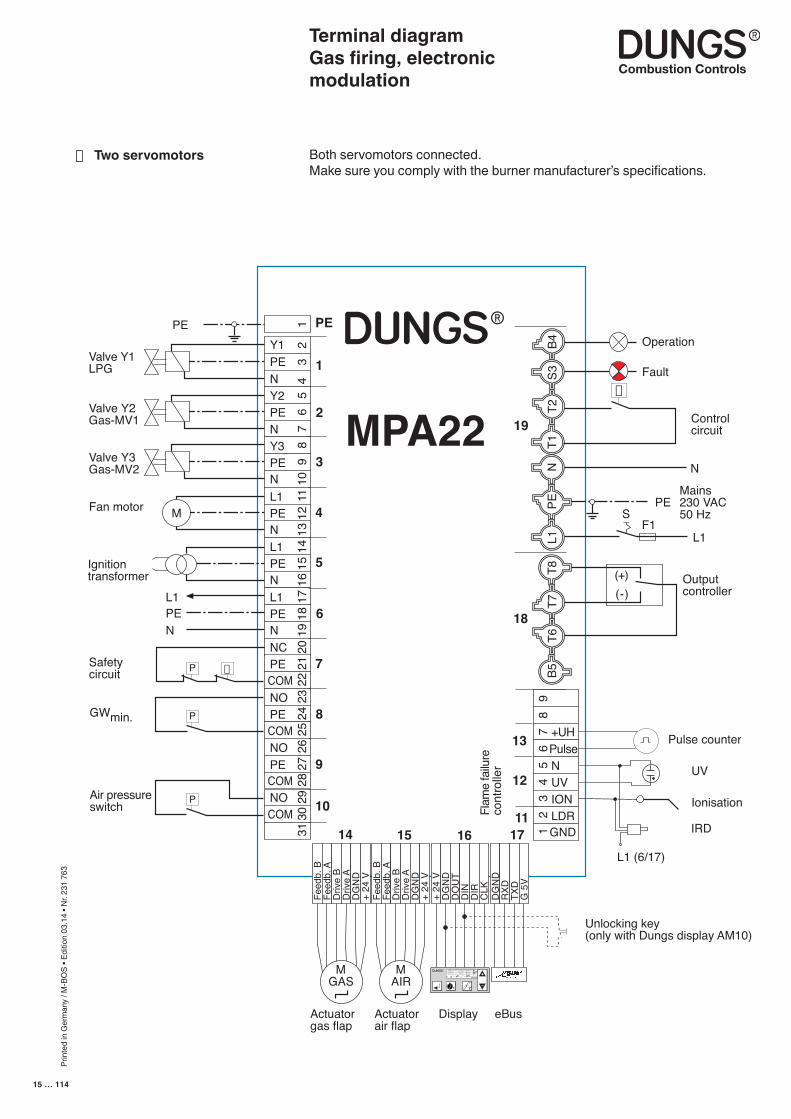
Terminal diagramGas firing, electronic modulation
■ Two servomotors Both servomotors connected.Make sure you comply with the burner manufacturer’s specifications.
L1PEN
MPA22
B4S3
T2N
L1PE
T8T7
T6B5
T1
Feed
b. B
Feed
b. A
Driv
e B
Driv
e A
DG
ND
+ 24
VFe
edb.
BFe
edb.
AD
rive
BD
rive
AD
GN
D+
24 V
M
MGAS
M AIR
P
PE
1
2
3
4
5
6
7
8
9
10
14 15 16 17
12Y1
N
34
5Y2
PE
67
89
PENY3PE
10N
11L1PEN
1213
14L1PE 15
N 1617L1
PE 18
N 1920NC
PE 21
COM 2223NO
PECOM
2425
26
PE 27
NO
COMNOCOM
2829
3031
9
+UH
87
65
43
21
PulseNUVIONLDR
+ 24
VD
GN
DD
OU
TD
IND
IRC
LKD
GN
DR
XDTX
DG
5V
Mains230 VAC50 Hz
Valve Y1LPG
Ignitiontransformer
Fan motor
Operation
Fault
L1
PE
N
PE
Safetycircuit
Valve Y2Gas-MV1
Valve Y3Gas-MV2
Pulse counter
UV
Ionisation
F1S
DisplayActuatorgas flap
eBusActuatorair flap
Flam
e fa
ilure
cont
rolle
r
(-)(+) Output
controller
Controlcircuit
Air pressureswitch
GWmin.
Unlocking key(only with Dungs display AM10)
IRD
L1 (6/17)
11
12
13
18
19
+
–
1 2
P S i G L/A
hl,m3
P
P
GND
Prin
ted
in G
erm
any
/ M-B
OS
• Edi
tion
03.1
4 • N
r. 23
1 76
3
16 … 114
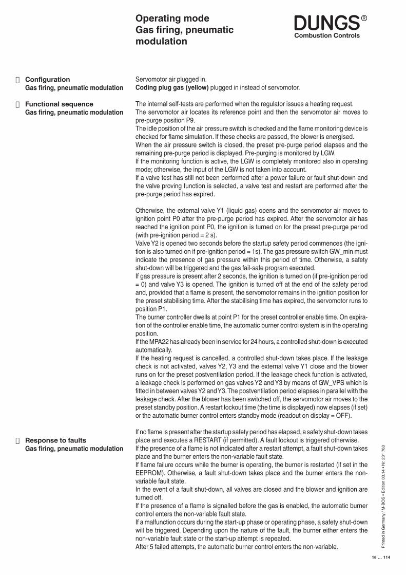
Servomotor air plugged in.Coding plug gas (yellow) plugged in instead of servomotor.
The internal self-tests are performed when the regulator issues a heating request.The servomotor air locates its reference point and then the servomotor air moves to pre-purge position P9.The idle position of the air pressure switch is checked and the flame monitoring device is checked for flame simulation. If these checks are passed, the blower is energised.When the air pressure switch is closed, the preset pre-purge period elapses and the remaining pre-purge period is displayed. Pre-purging is monitored by LGW.If the monitoring function is active, the LGW is completely monitored also in operating mode; otherwise, the input of the LGW is not taken into account.If a valve test has still not been performed after a power failure or fault shut-down and the valve proving function is selected, a valve test and restart are performed after the pre-purge period has expired.
Otherwise, the external valve Y1 (liquid gas) opens and the servomotor air moves to ignition point P0 after the pre-purge period has expired. After the servomotor air has reached the ignition point P0, the ignition is turned on for the preset pre-purge period (with pre-ignition period = 2 s).Valve Y2 is opened two seconds before the startup safety period commences (the igni-tion is also turned on if pre-ignition period = 1s). The gas pressure switch GW_min must indicate the presence of gas pressure within this period of time. Otherwise, a safety shut-down will be triggered and the gas fail-safe program executed.If gas pressure is present after 2 seconds, the ignition is turned on (if pre-ignition period = 0) and valve Y3 is opened. The ignition is turned off at the end of the safety period and, provided that a flame is present, the servomotor remains in the ignition position for the preset stabilising time. After the stabilising time has expired, the servomotor runs to position P1.The burner controller dwells at point P1 for the preset controller enable time. On expira-tion of the controller enable time, the automatic burner control system is in the operating position.If the MPA22 has already been in service for 24 hours, a controlled shut-down is executed automatically.If the heating request is cancelled, a controlled shut-down takes place. If the leakage check is not activated, valves Y2, Y3 and the external valve Y1 close and the blower runs on for the preset postventilation period. If the leakage check function is activated, a leakage check is performed on gas valves Y2 and Y3 by means of GW_VPS which is fitted in between valves Y2 and Y3. The postventilation period elapses in parallel with the leakage check. After the blower has been switched off, the servomotor air moves to the preset standby position. A restart lockout time (the time is displayed) now elapses (if set) or the automatic burner control enters standby mode (readout on display = OFF).
If no flame is present after the startup safety period has elapsed, a safety shut-down takes place and executes a RESTART (if permitted). A fault lockout is triggered otherwise.If the presence of a flame is not indicated after a restart attempt, a fault shut-down takes place and the burner enters the non-variable fault state.If flame failure occurs while the burner is operating, the burner is restarted (if set in the EEPROM). Otherwise, a fault shut-down takes place and the burner enters the non-variable fault state.In the event of a fault shut-down, all valves are closed and the blower and ignition are turned off.If the presence of a flame is signalled before the gas is enabled, the automatic burner control enters the non-variable fault state.If a malfunction occurs during the start-up phase or operating phase, a safety shut-down will be triggered. Depending upon the nature of the fault, the burner either enters the non-variable fault state or the start-up attempt is repeated.After 5 failed attempts, the automatic burner control enters the non-variable.
Operating modeGas firing, pneumatic modulation
■ Configuration Gas firing, pneumatic modulation
■ Functional sequence Gas firing, pneumatic modulation
■ Response to faults Gas firing, pneumatic modulation
Prin
ted
in G
erm
any
/ M-B
OS
• Edi
tion
03.1
4 • N
r. 23
1 76
3
17 … 114
Gas pressure switch GW_min is fitted upstream of the two gas valves of the Ratio control.If a pressure sufficient to actuate gas pressure switch GW_min does not build up one second before the startup safety period commences, burner start-up is interrupted. The valves are closed and the blower is switched off. The automatic burner control waits for 2 minutes before repeating the start-up attempt.If there is a still a shortage of gas after this 2-minute wait, the start-up attempt is repeated a third time after waiting another 2 minutes.After the third failed start-up attempt, the burner waits for an hour before at-tempting another restart.This function does not give rise to a fault lockout in the event of a gas shortage and reduces the frequency of start-up attempts if a gas shortage exists over a lengthy period of time.
Examples of a display during the wait period: 18 1-23 (= 1 minute 23 s remaining waiting time)
The waiting time can only be reset by disconnecting the voltage supply to the device (turn main switch OFF or disconnect the 7-pole connector).
You have the option of delaying the modulation speed. Make the setting using the EEPROM parameter "Modulation delay". If the value is set to 0, modulation occurs at maximum speed. Values between 1 and 15 reduce the speed. The higher the value, the slower the modulation.An exact speed cannot be set since the speed is dependent on the position of the setpoints.
■ Gas pressure switchingGas fail-safe program for gas burners with pneumatic modula-tion
■ Modulation delay
Operating modeGas firing, pneumatic modulation
Prin
ted
in G
erm
any
/ M-B
OS
• Edi
tion
03.1
4 • N
r. 23
1 76
3
18 … 114
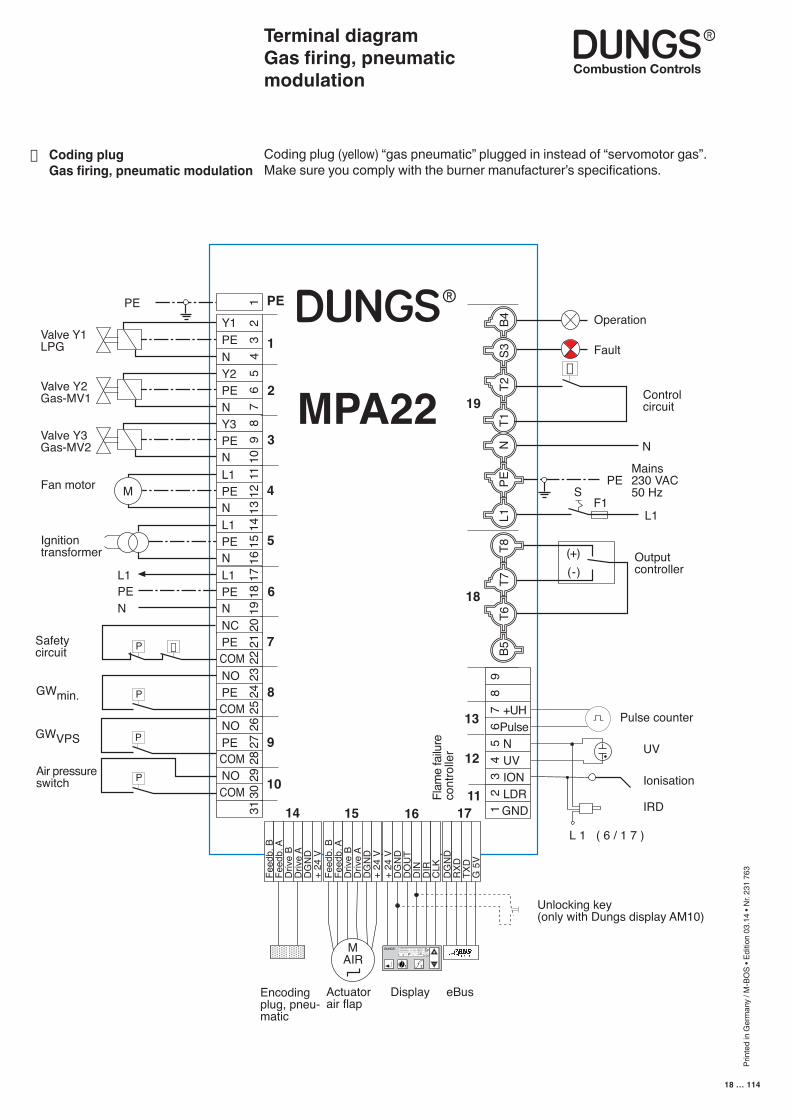
Terminal diagramGas firing, pneumatic modulation
■ Coding plug Gas firing, pneumatic modulation
Coding plug (yellow) “gas pneumatic” plugged in instead of “servomotor gas”.Make sure you comply with the burner manufacturer’s specifications.
L1PEN
MPA22
B4S3
T2N
L1PE
T8T7
T6B5
T1
Feed
b. B
Feed
b. A
Driv
e B
Driv
e A
DG
ND
+ 24
VFe
edb.
BFe
edb.
AD
rive
BD
rive
AD
GN
D+
24 V
M
P
M AIR
PE
1
2
3
4
5
6
7
8
9
10
14 15 16 17 IRD
L 1 ( 6 / 1 7 )
12Y1
N
34
5Y2
PE
67
89
PENY3PE
10N
11L1PEN
1213
14L1PE 15
N 1617L1
PE 18
N 1920NC
PE 21
COM 2223NO
PECOM
2425
26
PE 27
NO
COMNOCOM
2829
3031
9
+UH
87
65
43
21
PulseNUVIONLDR
+ 24
VD
GN
DD
OU
TD
IND
IRC
LKD
GN
DR
XDTX
DG
5V
Mains230 VAC50 Hz
Valve Y1LPG
Ignitiontransformer
Fan motor
Operation
Fault
L1
PE
N
PE
Valve Y2Gas-MV1
Valve Y3Gas-MV2
Pulse counter
UV
Ionisation
F1S
DisplayEncodingplug, pneu-matic
Actuatorair flap
Flam
e fa
ilure
cont
rolle
r
(-)(+) Output
controller
Controlcircuit
eBus
Safetycircuit
Air pressureswitch
GWmin.
GWVPS
Unlocking key(only with Dungs display AM10)
11
12
13
18
19
P
P
P
+
–
1 2
P S i G L/A
hl,m3
GND
Prin
ted
in G
erm
any
/ M-B
OS
• Edi
tion
03.1
4 • N
r. 23
1 76
3
19 … 114
Operating modeOil firing, three stage
Servomotor air plugged inCoding plug oil (black) plugged in instead of servomotor gas.
The internal self-tests are performed when the regulator issues a heating request.The servomotor air locates its reference point and then the servomotor air moves to preventilation position P9. Once the servomotor reaches this position, a 5-second delay commences.The air pressure switch is checked for idle state and the flame monitoring device is checked for flame simulation. If these checks are passed, the blower and the ignition are turned on.The preset pre-purge period elapses and the remaining pre-purge period is displayed. If the switch function has been activated, the preventilation cycle is monitored 3 s after switching on the blower. To ensure that the preventilation cycle is executed at the max. possible flow rate, the desired time should be increased by 3 s in the EEPROM. Once the pre-purge period elapses, the servomotor air moves to ignition point P0 and dwells there for 2 seconds, opens valve Y1 and (if exist) an additional pre-valve connected in parallel with Y1.The ignition cuts out at the end of the preset safety period and, provided that a flame is present, the servomotor air dwells in the ignition position for the preset stabilizing time. When the watchdog function is activated, oil pressure switch input (GW_min) is monitored after the valve opens. If you want to monitor the air pressure but not the gas pressure, a bridge can be attached to inlet GW_min as a substitute.
After the stabilising time elapses, the servomotor air moves to position P1 (stage 1). The burner controller dwells at point P1 for the preset controller enable time. On expi-ration of the controller enable time, the automatic burner control system accepts the signals applied to the capacity control inputs for the second and third stages (Stage 2 and Stage 3).
Changeover from the first stage to the second stage takes place within 6 s after the contact of the second stage closes. The servomotor air moves to the second stage P3 via changeover point P2 within t < 3 s, and valve Y2 (second stage) is connected when the servomotor passes the changeover point.
Changeover from the second stage to the third stage takes place within 6 s after the contact of the third stage closes. The servomotor air moves to the third stage P9 via changeover point P4 within t < 3 s, and valve Y3 (third stage) is connected when the servomotor passes the changeover point.
Changeover to the next lower stage is implemented in the reverse order.Once a changeover has been initiated it is completed.If the MPA22 has already been in service for 24 hours, a controlled shut-down is ex-ecuted automatically.If the heating request is cancelled, a controlled shut-down takes place. Valves Y1, Y2 and Y3 close and the blower runs on for the preset postventilation period.After the blower has been switched off, the servomotor air moves to the preset standby position. A restart lockout time (the time is displayed) now elapses (if set) or the auto-matic burner control enters standby mode (display = OFF).
■ Configuration Oil firing, three stage
■ Functional sequence Oil firing, three stage
Prin
ted
in G
erm
any
/ M-B
OS
• Edi
tion
03.1
4 • N
r. 23
1 76
3
20 … 114
Operating modeOil firing, three stage
If no flame is present after the startup safety period has elapsed, the burner enters the non-variable fault state.If flame failure occurs while the burner is operating, a fault shut-down takes place and the system executes a restart. If the presence of a flame is not signalled, the system enters the non-variable fault state.In the event of a fault shut-down, all valves are closed and the blower and ignition are turned off.If the presence of a flame is signalled before the gas is enabled, the automatic burner control enters the non-variable fault state.The type of fault or disturbance is displayed.If air pressure switch failure is detected during the startup period, provided the watchdog function is activated, a safety shut-down takes place and 5 restart at-tempts are performed; if this occurs when the burner is operating, the automatic burner control enters the non-variable fault state.If the oil pressure drops, the automatic burner control enters the non-variable fault state.
■ Response to faults Oil firing, three stage
Prin
ted
in G
erm
any
/ M-B
OS
• Edi
tion
03.1
4 • N
r. 23
1 76
3
21 … 114
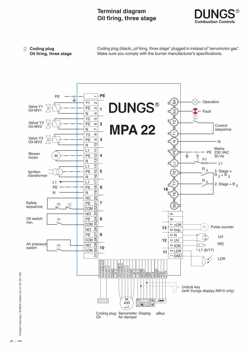
Terminal diagramOil firing, three stage
■ Coding plug Oil firing, three stage
Coding plug (black) „oil firing, three stage“ plugged in instead of “servomotor gas”.Make sure you comply with the burner manufacturer’s specifications.
L1PEN
MPA 22
B4S3
T2N
L1PE
T8T7
T6B5
T1
Ackn
owled
gem
ent B
Ackn
owled
gem
ent A
Activ
atio
n B
Activ
atio
n A
DG
ND
+ 24
VAc
know
ledge
me
Ackn
owled
gem
eAc
tivat
ion
BAc
tivat
ion
AD
GN
D+
24 V
M
P
M AIR
PE
1
2
3
4
5
6
7
8
9
10
12Y1
N
34
5Y2
PE
67
89
PENY3PE
10N
11L1PEN
1213
14L1PE 15
N 1617L1
PE 18
N 1920NC
PE 21
COM 2223NO
PECOM
2425
26
PE 27
NO
COMNOCOM
2829
3031
9
+UH
87
65
43
21
Imp.NUVIONLDR
+ 24
VD
GN
DD
OU
TD
IND
IRC
LKD
GN
DR
XDTX
DG
5V
Mains230 VAC50 Hz
Valve Y1Oil-MV1
Ignitiontransformer
Blowermotor
Operation
Fault
L1
PE
N
PE
Valvel Y2Oil-MV2
Valve Y3Oil-MV3
R 3
R 2
Pulse counter
UV
LDR
Unlock key(with Dungs display AM10 only)
F1S
DisplayServomotorAir damper
Coding plugOil
2. Stage = R 2
3. Stage =R 2 + R 3
Controlsequence
eBus
Safetysequence
Air pressureswitch
Oil switchmin.
IRD
11
12
13
18
GNDL1 (6/17)
+
–
1 2
P S i G L/A
hl,m3
P
P
Prin
ted
in G
erm
any
/ M-B
OS
• Edi
tion
03.1
4 • N
r. 23
1 76
3
22 … 114
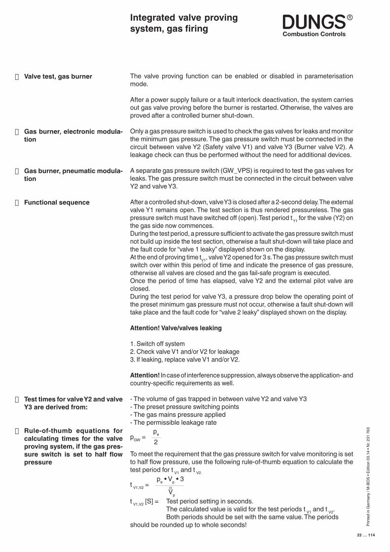
The valve proving function can be enabled or disabled in parameterisation mode.
After a power supply failure or a fault interlock deactivation, the system carries out gas valve proving before the burner is restarted. Otherwise, the valves are proved after a controlled burner shut-down.
Only a gas pressure switch is used to check the gas valves for leaks and monitor the minimum gas pressure. The gas pressure switch must be connected in the circuit between valve Y2 (Safety valve V1) and valve Y3 (Burner valve V2). A leakage check can thus be performed without the need for additional devices.
A separate gas pressure switch (GW_VPS) is required to test the gas valves for leaks. The gas pressure switch must be connected in the circuit between valve Y2 and valve Y3.
After a controlled shut-down, valve Y3 is closed after a 2-second delay. The external valve Y1 remains open. The test section is thus rendered pressureless. The gas pressure switch must have switched off (open). Test period t Y1 for the valve (Y2) on the gas side now commences.During the test period, a pressure sufficient to activate the gas pressure switch must not build up inside the test section, otherwise a fault shut-down will take place and the fault code for “valve 1 leaky” displayed shown on the display.At the end of proving time tV1, valve Y2 opened for 3 s. The gas pressure switch must switch over within this period of time and indicate the presence of gas pressure, otherwise all valves are closed and the gas fail-safe program is executed.Once the period of time has elapsed, valve Y2 and the external pilot valve are closed.During the test period for valve Y3, a pressure drop below the operating point of the preset minimum gas pressure must not occur, otherwise a fault shut-down will take place and the fault code for “valve 2 leaky” displayed shown on the display.
Attention! Valve/valves leaking
1. Switch off system2. Check valve V1 and/or V2 for leakage3. If leaking, replace valve V1 and/or V2.
Attention! In case of interference suppression, always observe the application- and country-specific requirements as well.
- The volume of gas trapped in between valve Y2 and valve Y3- The preset pressure switching points- The gas mains pressure applied- The permissible leakage rate
To meet the requirement that the gas pressure switch for valve monitoring is set to half flow pressure, use the following rule-of-thumb equation to calculate the test period for t V1 and t V2.
t V1,V2 [S] = Test period setting in seconds. The calculated value is valid for the test periods t V1 and t V2. Both periods should be set with the same value. The periods should be rounded up to whole seconds!
pe
2pGW =
Integrated valve proving system, gas firing
■ Valve test, gas burner
■ Gas burner, electronic modula-tion
■ Gas burner, pneumatic modula-tion
■ Functional sequence
■ Test times for valve Y2 and valve Y3 are derived from:
■ Rule-of-thumb equations for calculating times for the valve proving system, if the gas pres-sure switch is set to half flow pressure
pe • Vp • 3t V1,V2 =
Vp
Prin
ted
in G
erm
any
/ M-B
OS
• Edi
tion
03.1
4 • N
r. 23
1 76
3
23 … 114
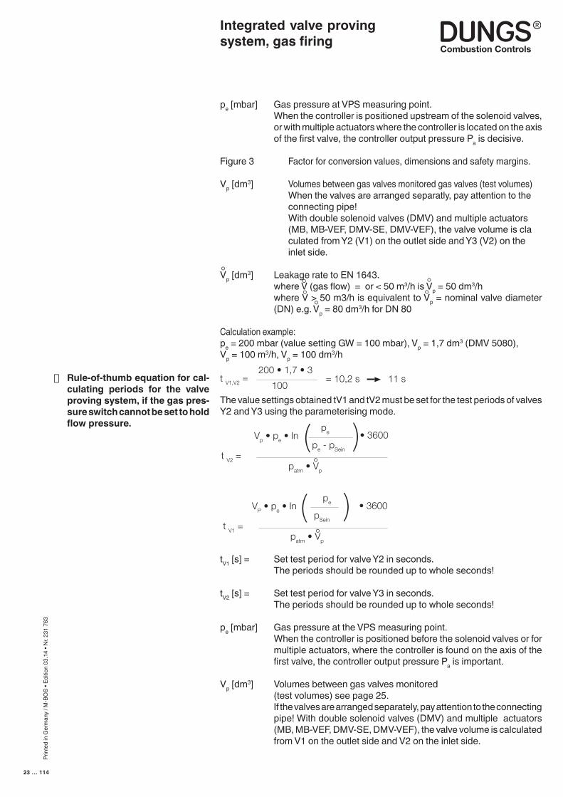
pe [mbar] Gas pressure at VPS measuring point. When the controller is positioned upstream of the solenoid valves,
or with multiple actuators where the controller is located on the axis of the first valve, the controller output pressure Pa is decisive.
Figure 3 Factor for conversion values, dimensions and safety margins.
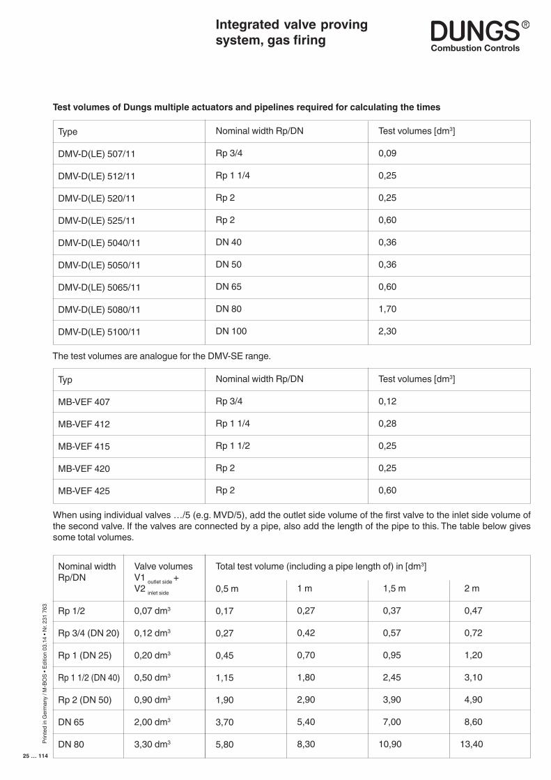
Vp [dm3] Volumes between gas valves monitored gas valves (test volumes) When the valves are arranged separatly, pay attention to the connecting pipe! With double solenoid valves (DMV) and multiple actuators (MB, MB-VEF, DMV-SE, DMV-VEF), the valve volume is cla culated from Y2 (V1) on the outlet side and Y3 (V2) on the inlet side.
Vp [dm3] Leakage rate to EN 1643. where V (gas flow) = or < 50 m3/h is Vp = 50 dm3/h where V > 50 m3/h is equivalent to Vp = nominal valve diameter
(DN) e.g. Vp = 80 dm3/h for DN 80
Calculation example:pe = 200 mbar (value setting GW = 100 mbar), Vp = 1,7 dm3 (DMV 5080),Vp = 100 m3/h, Vp = 100 dm3/h
The value settings obtained tV1 and tV2 must be set for the test periods of valves Y2 and Y3 using the parameterising mode.
tV1 [s] = Set test period for valve Y2 in seconds. The periods should be rounded up to whole seconds!
tV2 [s] = Set test period for valve Y3 in seconds. The periods should be rounded up to whole seconds!
pe [mbar] Gas pressure at the VPS measuring point. When the controller is positioned before the solenoid valves or for
multiple actuators, where the controller is found on the axis of the first valve, the controller output pressure Pa is important.
Vp [dm3] Volumes between gas valves monitored (test volumes) see page 25. If the valves are arranged separately, pay attention to the connecting
pipe! With double solenoid valves (DMV) and multiple actuators (MB, MB-VEF, DMV-SE, DMV-VEF), the valve volume is calculated from V1 on the outlet side and V2 on the inlet side.
■ Rule-of-thumb equation for cal-culating periods for the valve proving system, if the gas pres-sure switch cannot be set to hold flow pressure.
Integrated valve proving system, gas firing
200 • 1,7 • 3
100t V1,V2 = = 10,2 s 11 s
Vp • pe • In
t V2 =
pe
pe - pSein
patm • Vp
VP • pe • In
t V1 =
pe
pSein
patm • Vp
• 3600
• 3600
Prin
ted
in G
erm
any
/ M-B
OS
• Edi
tion
03.1
4 • N
r. 23
1 76
3
24 … 114
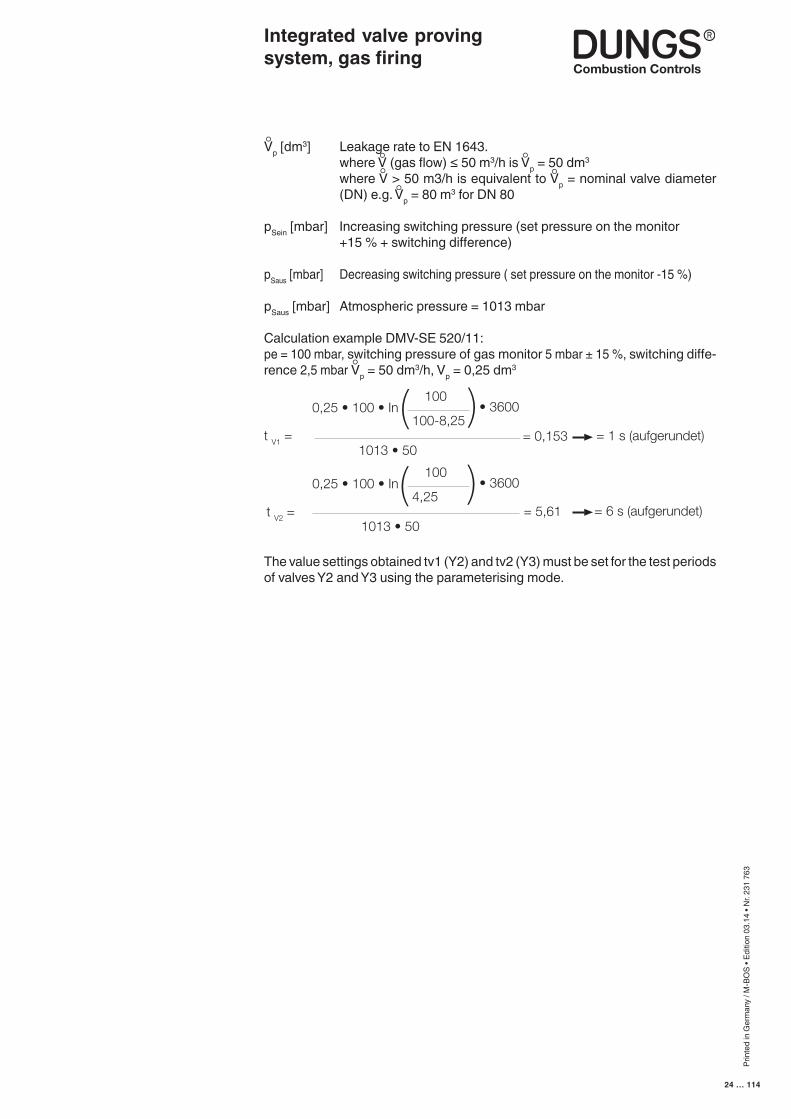
Vp [dm3] Leakage rate to EN 1643. where V (gas flow) ≤ 50 m3/h is Vp = 50 dm3
where V > 50 m3/h is equivalent to Vp = nominal valve diameter (DN) e.g. Vp = 80 m3 for DN 80
pSein [mbar] Increasing switching pressure (set pressure on the monitor +15 % + switching difference)
pSaus [mbar] Decreasing switching pressure ( set pressure on the monitor -15 %)
pSaus [mbar] Atmospheric pressure = 1013 mbar
Calculation example DMV-SE 520/11:pe = 100 mbar, switching pressure of gas monitor 5 mbar ± 15 %, switching diffe-rence 2,5 mbar Vp = 50 dm3/h, Vp = 0,25 dm3
The value settings obtained tv1 (Y2) and tv2 (Y3) must be set for the test periods of valves Y2 and Y3 using the parameterising mode.
Integrated valve proving system, gas firing
t V1 = 1013 • 50
0,25 • 100 • In100
100-8,25• 3600
= 0,153 = 1 s (aufgerundet)
t V2 = 1013 • 50
0,25 • 100 • In100
4,25• 3600
= 5,61 = 6 s (aufgerundet)
Prin
ted
in G
erm
any
/ M-B
OS
• Edi
tion
03.1
4 • N
r. 23
1 76
3
25 … 114
Integrated valve proving system, gas firing
Test volumes of Dungs multiple actuators and pipelines required for calculating the times
The test volumes are analogue for the DMV-SE range.
Type
DMV-D(LE) 507/11
DMV-D(LE) 512/11
DMV-D(LE) 520/11
DMV-D(LE) 525/11
DMV-D(LE) 5040/11
DMV-D(LE) 5050/11
DMV-D(LE) 5065/11
DMV-D(LE) 5080/11
DMV-D(LE) 5100/11
Nominal width Rp/DN
Rp 3/4
Rp 1 1/4
Rp 2
Rp 2
DN 40
DN 50
DN 65
DN 80
DN 100
Test volumes [dm3]
0,09
0,25
0,25
0,60
0,36
0,36
0,60
1,70
2,30
Typ
MB-VEF 407
MB-VEF 412
MB-VEF 415
MB-VEF 420
MB-VEF 425
Nominal width Rp/DN
Rp 3/4
Rp 1 1/4
Rp 1 1/2
Rp 2
Rp 2
Test volumes [dm3]
0,12
0,28
0,25
0,25
0,60
Nominal widthRp/DN
Rp 1/2
Rp 3/4 (DN 20)
Rp 1 (DN 25)
Rp 1 1/2 (DN 40)
Rp 2 (DN 50)
DN 65
DN 80
0,5 m
0,17
0,27
0,45
1,15
1,90
3,70
5,80
1,5 m
0,37
0,57
0,95
2,45
3,90
7,00
10,90
Valve volumesV1 outlet side +V2 inlet side
0,07 dm3
0,12 dm3
0,20 dm3
0,50 dm3
0,90 dm3
2,00 dm3
3,30 dm3
When using individual valves …/5 (e.g. MVD/5), add the outlet side volume of the first valve to the inlet side volume of the second valve. If the valves are connected by a pipe, also add the length of the pipe to this. The table below gives some total volumes.
1 m
0,27
0,42
0,70
1,80
2,90
5,40
8,30
2 m
0,47
0,72
1,20
3,10
4,90
8,60
13,40
Total test volume (including a pipe length of) in [dm3]
Prin
ted
in G
erm
any
/ M-B
OS
• Edi
tion
03.1
4 • N
r. 23
1 76
3
26 … 114
Time diagramGas firing, electronic modulation
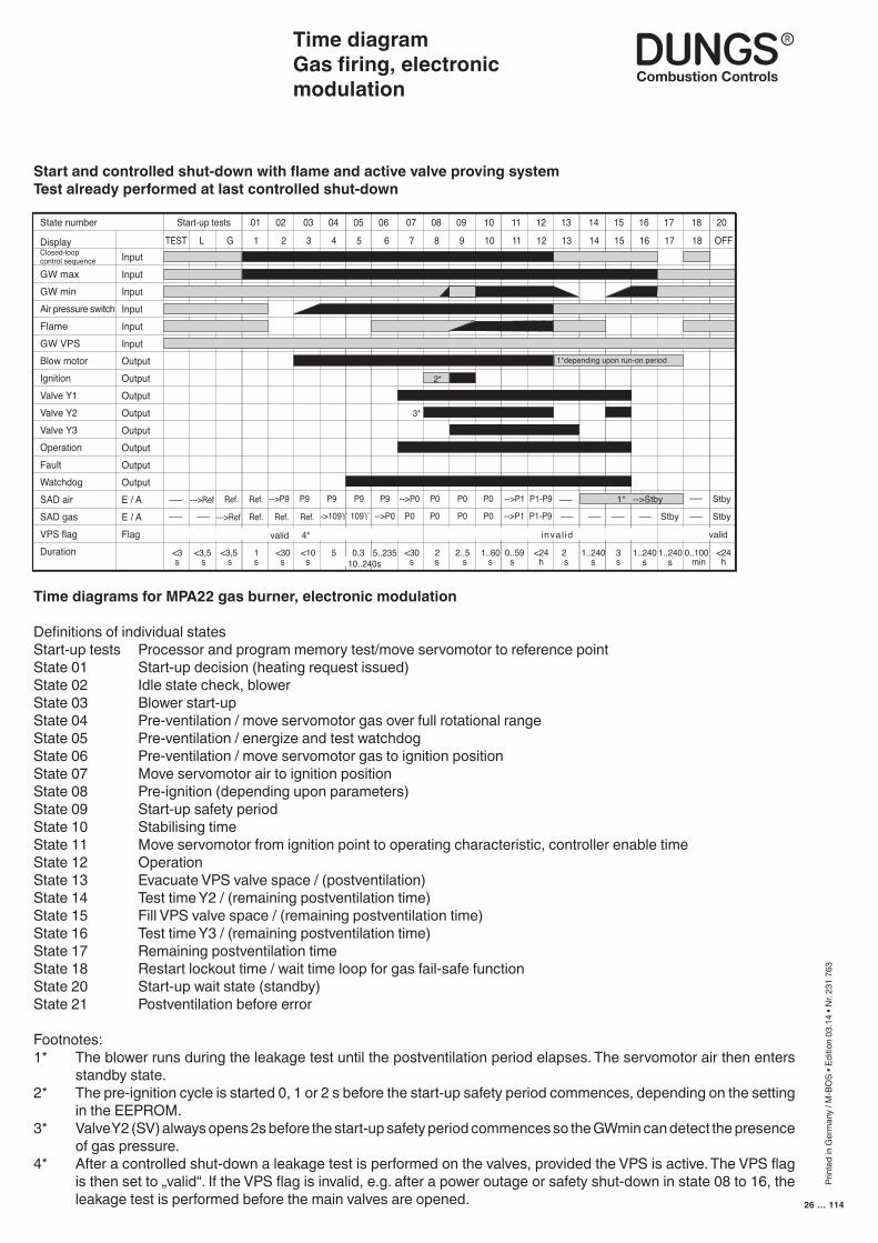
Time diagrams for MPA22 gas burner, electronic modulation
Definitions of individual statesStart-up tests Processor and program memory test/move servomotor to reference pointState 01 Start-up decision (heating request issued)State 02 Idle state check, blowerState 03 Blower start-upState 04 Pre-ventilation / move servomotor gas over full rotational rangeState 05 Pre-ventilation / energize and test watchdogState 06 Pre-ventilation / move servomotor gas to ignition positionState 07 Move servomotor air to ignition positionState 08 Pre-ignition (depending upon parameters)State 09 Start-up safety periodState 10 Stabilising timeState 11 Move servomotor from ignition point to operating characteristic, controller enable timeState 12 OperationState 13 Evacuate VPS valve space / (postventilation)State 14 Test time Y2 / (remaining postventilation time)State 15 Fill VPS valve space / (remaining postventilation time)State 16 Test time Y3 / (remaining postventilation time)State 17 Remaining postventilation timeState 18 Restart lockout time / wait time loop for gas fail-safe functionState 20 Start-up wait state (standby)State 21 Postventilation before error
Footnotes:1* The blower runs during the leakage test until the postventilation period elapses. The servomotor air then enters
standby state.2* The pre-ignition cycle is started 0, 1 or 2 s before the start-up safety period commences, depending on the setting
in the EEPROM.3* Valve Y2 (SV) always opens 2s before the start-up safety period commences so the GWmin can detect the presence
of gas pressure.4* After a controlled shut-down a leakage test is performed on the valves, provided the VPS is active. The VPS flag
is then set to „valid“. If the VPS flag is invalid, e.g. after a power outage or safety shut-down in state 08 to 16, the leakage test is performed before the main valves are opened.
Start and controlled shut-down with flame and active valve proving systemTest already performed at last controlled shut-down
Start-up tests 01 02 03 04 05 06 07 08 09 10 11 12 13 14 15 16 17 18 20State number
DisplayClosed-loopcontrol sequence
GW maxGW minAir pressure switchFlameGW VPSBlow motorIgnitionValve Y1Valve Y2Valve Y3OperationFaultWatchdogSAD airSAD gasVPS flagDuration
InputInputInputInputInputInputOutputOutputOutputOutputOutputOutputOutputOutputE / AE / AFlag
TEST L G 1 2 3 4 5 6 7 8 9 10 11 12 13 14 15 16 17 18 OFF
Zeitdiagramme für MPA22 Gasbrenner elektronisch modulierend
valid 4*
1*depending upon run-on period
<3 s
--->Ref Ref. P9P9-->P9 P9 P9 -->P0 P0 P0 P0 -->P1–––
––– ––– --->Ref Ref. Ref. Ref.
Ref. P1-P9 –––
->109ϒ 109ϒ P0-->P0 P0 P0 P0 -->P1 P1-P9 ––– ––– ––– ––– Stby ––– Stby
1* -->Stby Stby–––
2*
3*
<3,5 s
<3,5 s
1 s
<30 s
<10 s
5 0,3 5..235 <30 s
2 s
2..5 s
1..60 s
0..59 s
<24 h
2 s
1..240 s
3 s
0..100 min 10..240s
1..240 s
1..240 s
<24 h
inval id valid
Prin
ted
in G
erm
any
/ M-B
OS
• Edi
tion
03.1
4 • N
r. 23
1 76
3
27 … 114
Time diagramGas firing, electronic modulation
Start-up tests 01 02 03 04 05 06 07 08 09 Start-up tests 01 02 03 04 05 06 07 08 09 99State number
DisplayClosed-loopcontrol sequence
GW maxGW minAir pressure switchFlameGW VPSBlow motorIgnitionValve Y1Valve Y2Valve Y3OperationFaultWatchdogSAD airSAD gasVPS flagDuration
InputInputInputInputInputInputOutputOutputOutputOutputOutputOutputOutputOutputE / AE / AFlag
TEST L G 1 2 3 4 5 6 7 8 9 TEST L G 1 2 3 4 5 6 7 8 9 F xxh
<3 s
--->Ref Ref. P9P9-->P9 P9 P9 -->P0 P0 P0–––
––– ––– --->Ref Ref. Ref. Ref.
Ref.
->109ϒ 109ϒ P0-->P0 P0 P0
2*
3*
<3,5 s
<3,5 s
1 s
<30 s
<10 s
5 0,3 5..235 <30 s
2 s
2..5 s 10..240 s
disregarded 4*
2*
3*
<3 s
--->Ref Ref. P9P9-->P9 P9 P9 -->P0 P0 P0–––
––– ––– --->Ref Ref. Ref. Ref.
Ref.
->109ϒ 109ϒ P0-->P0 P0 P0
<3,5 s
<3,5 s
1 s
<30 s
<10 s
5 0,3 5..235 <30 s
2 s
2..5 s 10..240 s
–––
–––
>---> 12 12 Start-up tests 01 02 03 04 05 06 07 08 09 99State number
DisplayClosed-loopcontrol sequence
GW maxGW minAir pressure switchFlameGW VPSBlow motorIgnitionValve Y1Valve Y2Valve Y3OperationFaultWatchdogSAD airSAD gasVPS flagDuration
InputInputInputInputInputInputOutputOutputOutputOutputOutputOutputOutputOutputE / AE / AFlag
12 12 TEST L G 1 2 3 4 5 6 7 8 9 F xxh >---> >---> >---> >---> >---> >---> >---> >---> >---> >---> >---> >---> >---> >--->
>---> >--->
<3 s
--->Ref Ref. P9P9-->P9 P9 P9 -->P0 P0 P0
--->Ref Ref. Ref. Ref.
Ref.P1-P9
->109ϒ 109ϒ -->P0 P0 P0 P0 –––
–––
2*
3*
<3,5 s
<3,5 s
1 s
<30 s
<10 s
5 0,3 5..235 <30 s
2 s
2..5 s
<24 h 10..240 s
disregarded
P1-P9 –––
P1-P9 P1-P9 ––– –––
<1 s
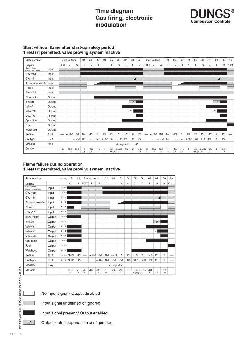
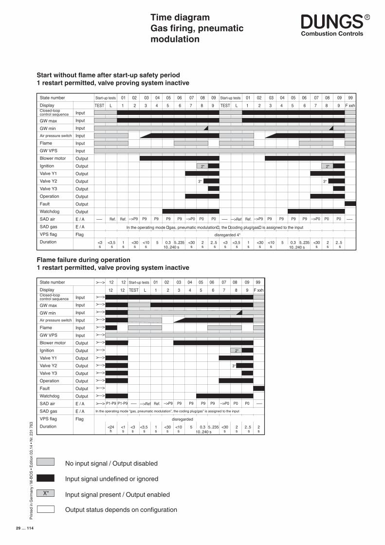
Start without flame after start-up safety period1 restart permitted, valve proving system inactive
Flame failure during operation1 restart permitted, valve proving system inactive
X*
No input signal / Output disabled
Input signal undefined or ignored
Input signal present / Output enabled
Output status depends on configurationX*X*
X*
Prin
ted
in G
erm
any
/ M-B
OS
• Edi
tion
03.1
4 • N
r. 23
1 76
3
28 … 114
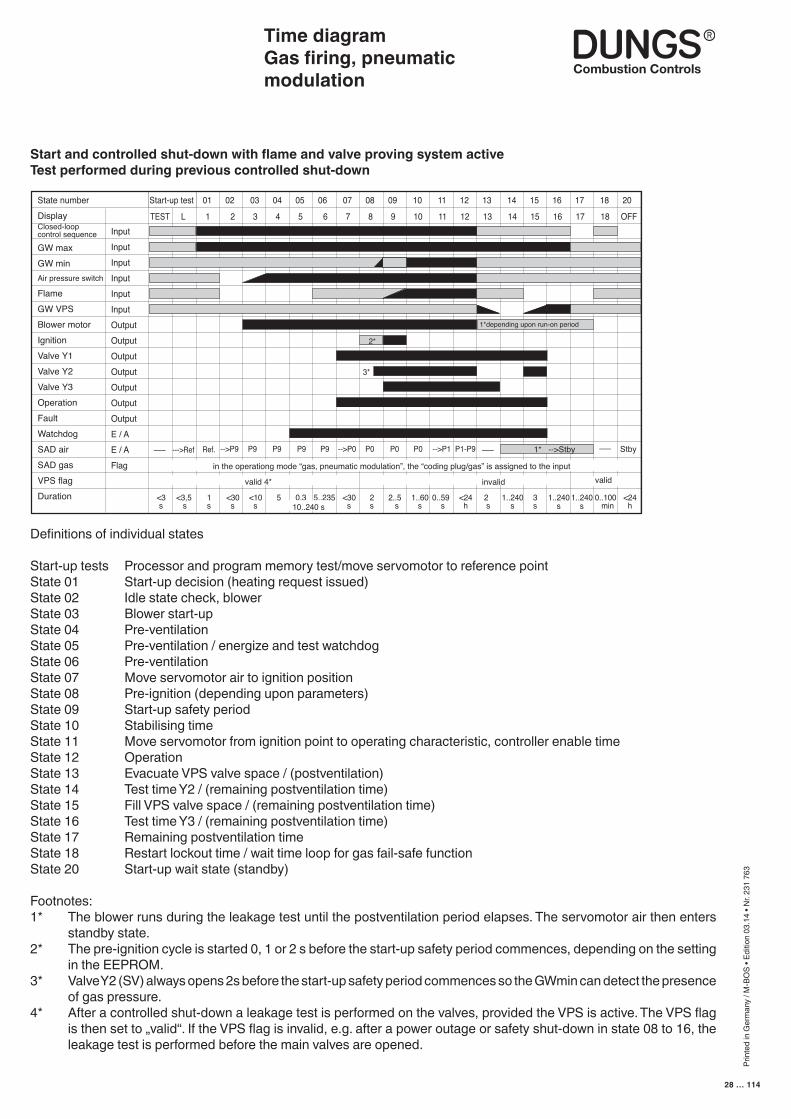
Time diagramGas firing, pneumatic modulation
Definitions of individual states
Start-up tests Processor and program memory test/move servomotor to reference pointState 01 Start-up decision (heating request issued)State 02 Idle state check, blowerState 03 Blower start-upState 04 Pre-ventilationState 05 Pre-ventilation / energize and test watchdogState 06 Pre-ventilationState 07 Move servomotor air to ignition positionState 08 Pre-ignition (depending upon parameters)State 09 Start-up safety periodState 10 Stabilising timeState 11 Move servomotor from ignition point to operating characteristic, controller enable timeState 12 OperationState 13 Evacuate VPS valve space / (postventilation)State 14 Test time Y2 / (remaining postventilation time)State 15 Fill VPS valve space / (remaining postventilation time)State 16 Test time Y3 / (remaining postventilation time)State 17 Remaining postventilation timeState 18 Restart lockout time / wait time loop for gas fail-safe functionState 20 Start-up wait state (standby)
Footnotes:1* The blower runs during the leakage test until the postventilation period elapses. The servomotor air then enters
standby state.2* The pre-ignition cycle is started 0, 1 or 2 s before the start-up safety period commences, depending on the setting
in the EEPROM.3* Valve Y2 (SV) always opens 2s before the start-up safety period commences so the GWmin can detect the presence
of gas pressure.4* After a controlled shut-down a leakage test is performed on the valves, provided the VPS is active. The VPS flag
is then set to „valid“. If the VPS flag is invalid, e.g. after a power outage or safety shut-down in state 08 to 16, the leakage test is performed before the main valves are opened.
Start-up test 01 02 03 04 05 06 07 08 09 10 11 12 13 14 15 16 17 18 20State numberDisplayClosed-loopcontrol sequence
GW maxGW minAir pressure switch
FlameGW VPSBlower motorIgnitionValve Y1Valve Y2Valve Y3OperationFaultWatchdogSAD airSAD gasVPS flagDuration
InputInputInputInputInputInputOutputOutputOutputOutputOutputOutputOutputE / AE / AFlag
TEST L 1 2 3 4 5 6 7 8 9 10 11 12 13 14 15 16 17 18 OFF
<3 s
--->Ref P9P9-->P9 P9 P9 -->P0 P0 P0 P0 -->P1––– Ref. P1-P9 ––– 1* -->Stby Stby–––
1*depending upon run-on period
2*
3*
<3,5 s
1 s
<30 s
<10 s
5 0,3 5..235 <30 s
2 s
2..5 s
1..60 s
0..59 s
<24 h
2 s
1..240 s
3 s
0..100 min 10..240 s
1..240 s
1..240 s
<24 h
valid 4*
in the operationg mode “gas, pneumatic modulation”, the “coding plug/gas” is assigned to the input
invalid valid
Start and controlled shut-down with flame and valve proving system activeTest performed during previous controlled shut-down
Prin
ted
in G
erm
any
/ M-B
OS
• Edi
tion
03.1
4 • N
r. 23
1 76
3
29 … 114
Time diagramGas firing, pneumatic modulation
Start-up tests 01 02 03 04 05 06 07 08 09 Start-up tests 01 02 03 04 05 06 07 08 09 99State numberDisplayClosed-loopcontrol sequence
GW maxGW minAir pressure switch
FlameGW VPSBlower motorIgnitionValve Y1Valve Y2Valve Y3OperationFaultWatchdogSAD airSAD gasVPS flagDuration
InputInputInputInputInputInputOutputOutputOutputOutputOutputOutputOutputOutputE / AE / AFlag
TEST L 1 2 3 4 5 6 7 8 9 TEST L 1 2 3 4 5 6 7 8 9 F xxh
<3 s
Ref. P9P9-->P9 P9 P9 -->P0 P0 P0––– Ref.
2*
3*
<3,5 s
1 s
<30 s
<10 s
5 0,3 5..235 <30 s
2 s
2..5 s
disregarded 4*
2*
3*
<3 s
--->Ref P9P9-->P9 P9 P9 -->P0 P0 P0––– Ref.
<3,5 s
1 s
<30 s
<10 s
5 0,3 5..235 <30 s
2 s
2..5 s 10..240 s
–––
In the operating mode �gas, pneumatic modulation�, the �coding plug/gas� is assigned to the input
10..240 s
>---> 12 12 Start-up tests 01 02 03 04 05 06 07 08 09 99State numberDisplayClosed-loopcontrol sequence
GW maxGW minAir pressure switch
FlameGW VPSBlower motorIgnitionValve Y1Valve Y2Valve Y3OperationFaultWatchdogSAD airSAD gasVPS flagDuration
InputInputInputInputInputInputOutputOutputOutputOutputOutputOutputOutputOutputE / AE / AFlag
12 12 TEST L 1 2 3 4 5 6 7 8 9 F xxh >---> >---> >---> >---> >---> >---> >---> >---> >---> >---> >---> >---> >---> >--->
>--->
<3 s
--->Ref P9P9-->P9 P9 P9 -->P0 P0 P0 Ref.P1-P9 –––
2*
3*
<3,5 s
1 s
<30 s
<10 s
5 0,3 5..235 <30 s
2 s
2..5 s
<24 h
2 s 10..240 s
disregarded
P1-P9 –––
<1 s
In the operating mode “gas, pneumatic modulation”, the coding plug/gas” is assigned to the input
Start without flame after start-up safety period1 restart permitted, valve proving system inactive
Flame failure during operation1 restart permitted, valve proving system inactive
X*
No input signal / Output disabled
Input signal undefined or ignored
Input signal present / Output enabled
Output status depends on configuration
X*X*X*
Prin
ted
in G
erm
any
/ M-B
OS
• Edi
tion
03.1
4 • N
r. 23
1 76
3
30 … 114
Time diagramOil firing, three stage
Definitions of individual states
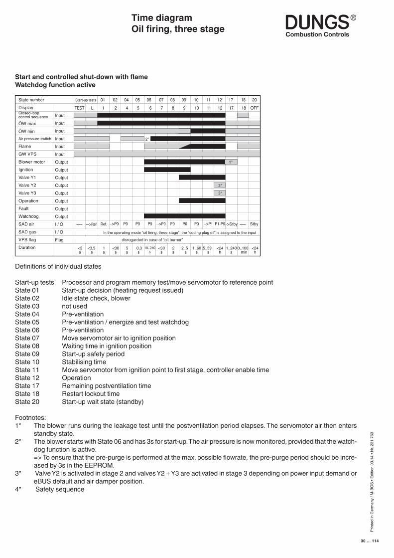
Start-up tests Processor and program memory test/move servomotor to reference pointState 01 Start-up decision (heating request issued)State 02 Idle state check, blowerState 03 not usedState 04 Pre-ventilationState 05 Pre-ventilation / energize and test watchdogState 06 Pre-ventilationState 07 Move servomotor air to ignition positionState 08 Waiting time in ignition positionState 09 Start-up safety periodState 10 Stabilising timeState 11 Move servomotor from ignition point to first stage, controller enable timeState 12 OperationState 17 Remaining postventilation timeState 18 Restart lockout timeState 20 Start-up wait state (standby)
Footnotes:1* The blower runs during the leakage test until the postventilation period elapses. The servomotor air then enters
standby state.2* The blower starts with State 06 and has 3s for start-up. The air pressure is now monitored, provided that the watch-
dog function is active. => To ensure that the pre-purge is performed at the max. possible flowrate, the pre-purge period should be incre-
ased by 3s in the EEPROM.3* Valve Y2 is activated in stage 2 and valves Y2 + Y3 are activated in stage 3 depending on power input demand or
eBUS default and air damper position.4* Safety sequence
Start-up tests 01 02 04 05 06 07 08 09 10 11 12 17 18 20State numberDisplayClosed-loopcontrol sequence
ÖW maxÖW minAir pressure switch
FlameGW VPSBlower motorIgnitionValve Y1Valve Y2Valve Y3OperationFaultWatchdogSAD airSAD gasVPS flagDuration
InputInputInputInputInputInputOutputOutputOutputOutputOutputOutputOutputOutputI / OI / OFlag
TEST L 1 2 4 5 6 7 8 9 10 11 12 17 18 OFF
<3 s
--->Ref P9P9-->P9 P9 -->P0 P0 P0 P0 -->P1––– Ref. P1-P9 –––->Stby Stby
1*
3*
<3,5 s
1 s
<30 s
5 s
0,3 s
10..240 s
<30 s
2 s
2..5 s
1..60 s
5..59 s
<24 h
1..240 s
0..100 min
<24 h
disregarded in case of “oil burner”
In the operating mode “oil firing, three stage”, the “coding plug oil” is assigned to the input
3*
2*
Start and controlled shut-down with flameWatchdog function active
Prin
ted
in G
erm
any
/ M-B
OS
• Edi
tion
03.1
4 • N
r. 23
1 76
3
31 … 114
Time diagramOil firing, three stage
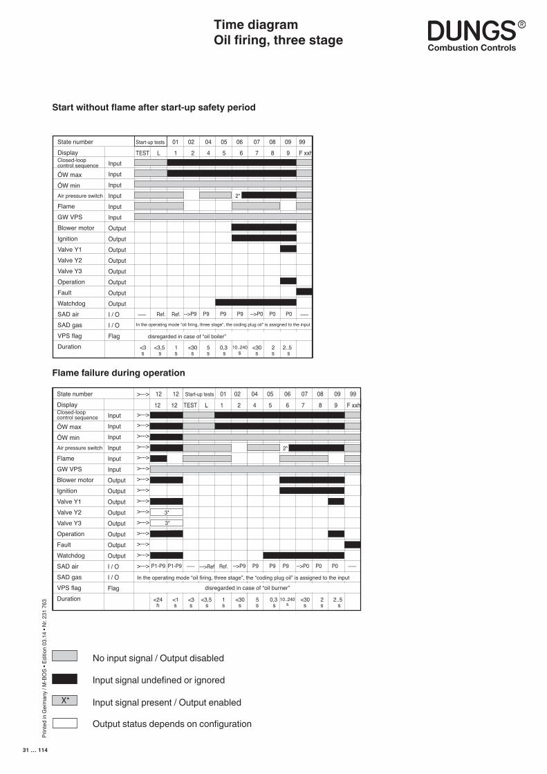
Start without flame after start-up safety period
Start-up tests 01 02 04 05 06 07 08 09 99State numberDisplayClosed-loopcontrol sequence
ÖW maxÖW minAir pressure switch
FlameGW VPSBlower motorIgnitionValve Y1Valve Y2Valve Y3OperationFaultWatchdogSAD airSAD gasVPS flagDuration
InputInputInputInputInputInputOutputOutputOutputOutputOutputOutputOutputOutputI / OI / OFlag
TEST L 1 2 4 5 6 7 8 9 F xxh
<3 s
Ref. P9P9-->P9 P9 -->P0 P0 P0––– Ref.
2*
<3,5 s
1 s
<30 s
5 s
<30 s
2 s
2..5 s
0,3 s
–––
10..240 s
disregarded in case of “oil boiler”
In the operating mode “oil firing, three stage”, the coding plug oil” is assigned to the input
12 12 TEST L 1 2 4 5 6 7 8 9 F xxh
>---> 12 12 Start-up tests 01 02 04 05 06 07 08 09 99State numberDisplayClosed-loopcontrol sequence
ÖW maxÖW minAir pressure switch
FlameGW VPSBlower motorIgnitionValve Y1Valve Y2Valve Y3OperationFaultWatchdogSAD airSAD gasVPS flagDuration
InputInputInputInputInputInputOutputOutputOutputOutputOutputOutputOutputOutputI / OI / OFlag
>---> >---> >---> >---> >---> >---> >---> >---> >---> >---> >---> >---> >---> >--->
>--->
In the operating mode “oil firing, three stage”, the “coding plug oil” is assigned to the input
<3 s
--->Ref P9-->P9 P9 P9 -->P0 P0 P0 Ref.P1-P9 –––
<3,5 s
1 s
<30 s
5 s
0,3 s
<30 s
2 s
2..5 s
<24 h
10..240 s
P1-P9 –––
<1 s
disregarded in case of “oil burner”
2*
3*
3*
Flame failure during operation
X*
No input signal / Output disabled
Input signal undefined or ignored
Input signal present / Output enabled
Output status depends on configuration
X*X*X*
Prin
ted
in G
erm
any
/ M-B
OS
• Edi
tion
03.1
4 • N
r. 23
1 76
3
32 … 114
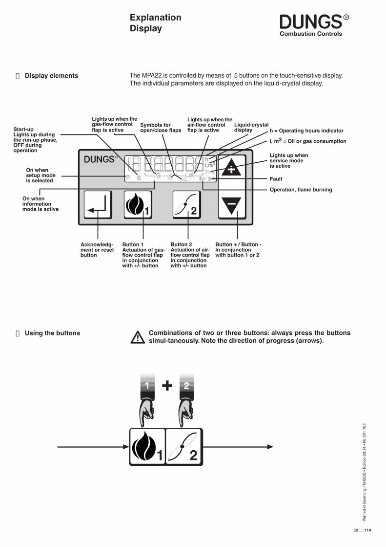
The MPA22 is controlled by means of 5 buttons on the touch-sensitive display.The individual parameters are displayed on the liquid-crystal display.
Combinations of two or three buttons: always press the buttons simul-taneously. Note the direction of progress (arrows).
Explanation Display
■ Display elements
■ Using the buttons
1 2
1 2+
Prin
ted
in G
erm
any
/ M-B
OS
• Edi
tion
03.1
4 • N
r. 23
1 76
3
33 … 114
Display functions
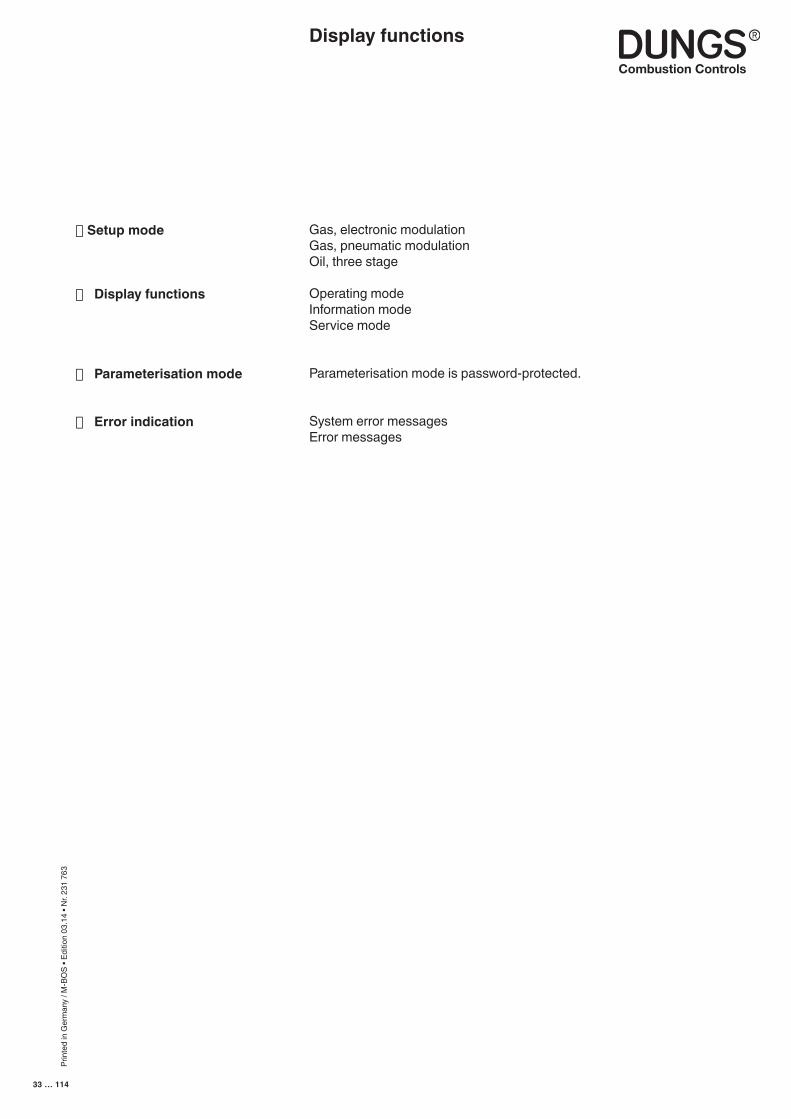
Gas, electronic modulationGas, pneumatic modulationOil, three stage
Operating modeInformation modeService mode
Parameterisation mode is password-protected.
System error messagesError messages
■Setup mode
■ Display functions
■ Parameterisation mode
■ Error indication
Prin
ted
in G
erm
any
/ M-B
OS
• Edi
tion
03.1
4 • N
r. 23
1 76
3
34 … 114
Relationships between the individual display modes
RESET
IDO.K.?
No lD
Password entry
Passwordcorrect?
No
Yes
No
Yes
Fault interlock?
No
Yes
Display duringstart tests
1
Error
Press approx. 0.5 s
Switch on linevoltage
ConfigurationLoad
1
2
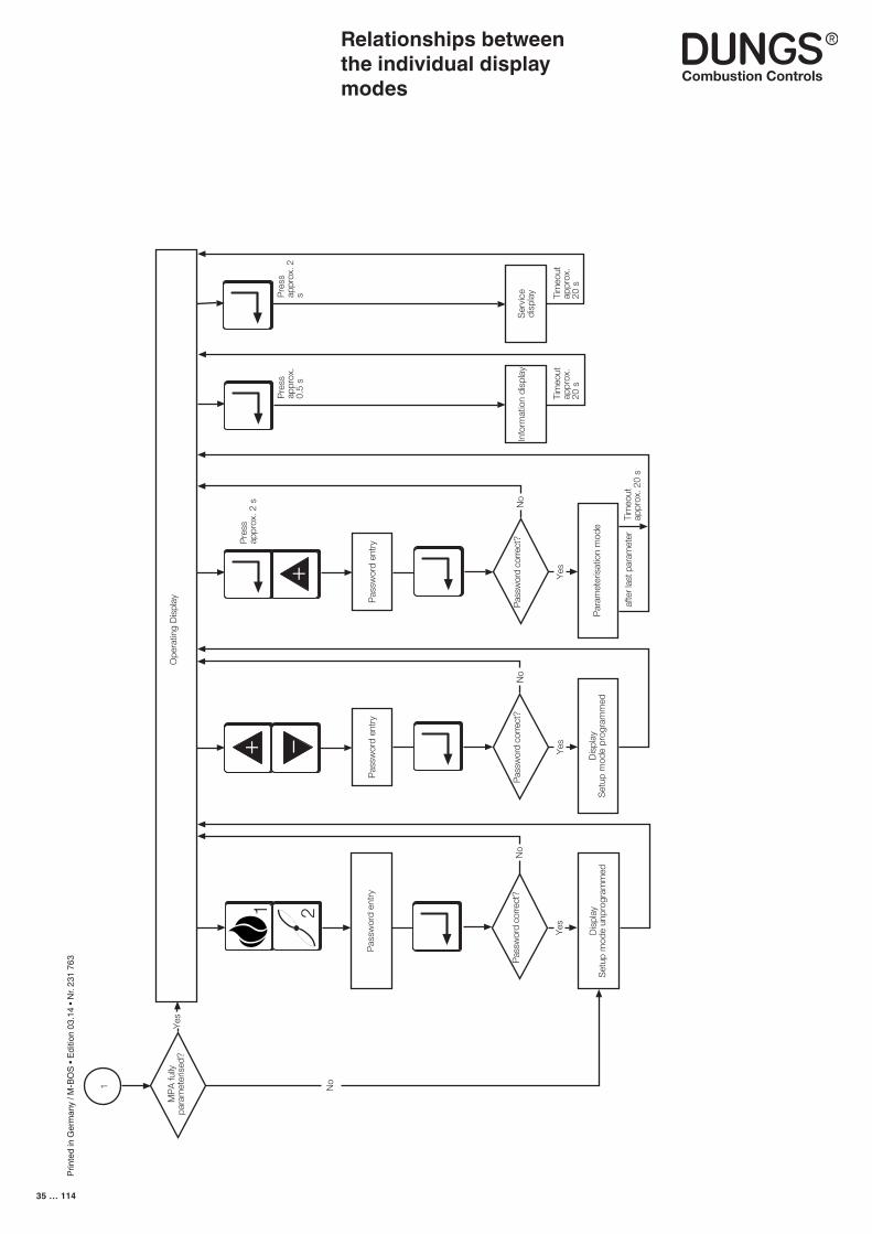
Prin
ted
in G
erm
any
/ M-B
OS
• Edi
tion
03.1
4 • N
r. 23
1 76
3
35 … 114
�
� �
������
�����
���
����
���
����
����
��������
���
����
��
���
���
����
���
������
�������
���
����
� ���
���
���
��
���
����
��
���
���
����
���
������
�������
���
����
� ����
���
��
�
���
����
��
���
���
����
���
������
��
���
����
����
�����
���
����
������
���
��
�
���������
�����
������
���
����
����
�����
���
���
����
���
���
���
���
����
����
���
����
���
����
����
���
���
���
����
���
��� ���
����
����
���
����
���
����
����
����
��
��
��
��
��
�
��
��
Relationships between the individual display modes

Prin
ted
in G
erm
any
/ M-B
OS
• Edi
tion
03.1
4 • N
r. 23
1 76
3
36 … 114
Display during standby
The automatic burner-control system is on standby following a controlled shut-down. No pending request for heat.
The automatic burner-control system is on standby because line voltage is too low.
The automatic burner-control system is on standby because the safety circuit is interrupted.
The automatic burner-control system is on standby because the signal for start prevention is applied via the eBUS.
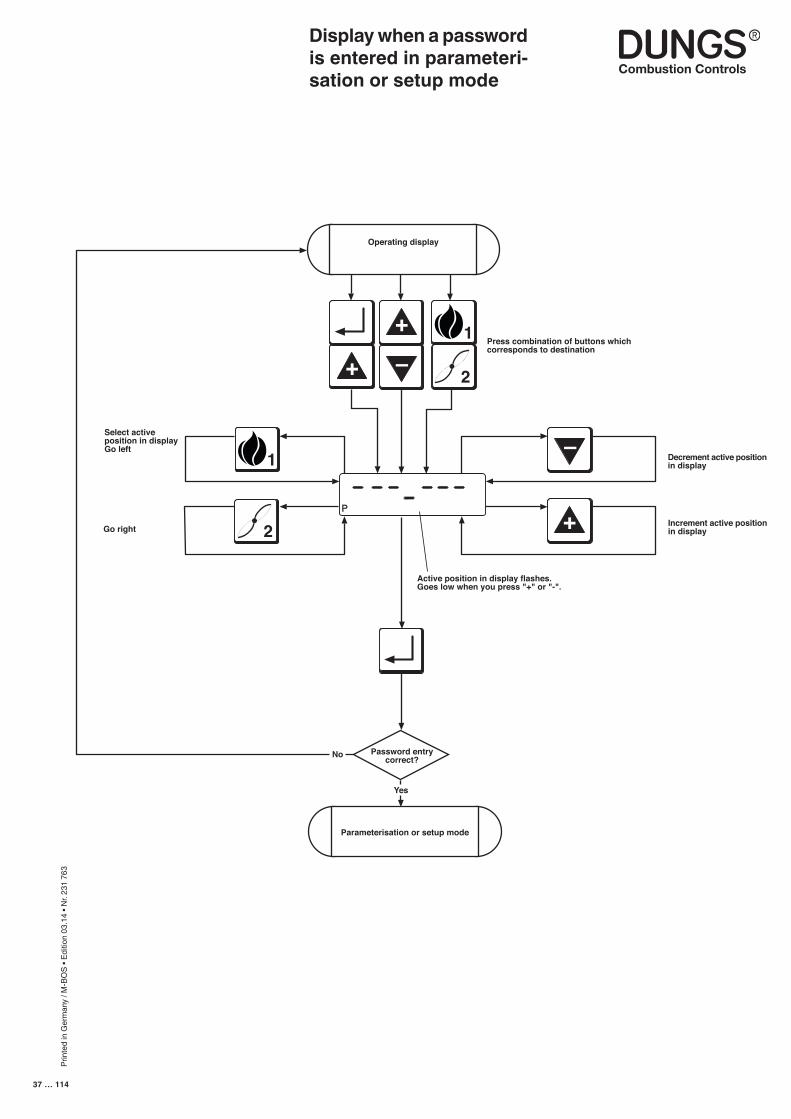
Prin
ted
in G
erm
any
/ M-B
OS
• Edi
tion
03.1
4 • N
r. 23
1 76
3
37 … 114
Display when a password is entered in parameteri-sation or setup mode
+
Active position in display flashes.Goes low when you press "+" or "-".
P
–
+2
Select activeposition in displayGo left
1
+
–
2
1
Operating display
Password entrycorrect?
Yes
Parameterisation or setup mode
Go right
No
Decrement active positionin display
Increment active positionin display
Press combination of buttons whichcorresponds to destination
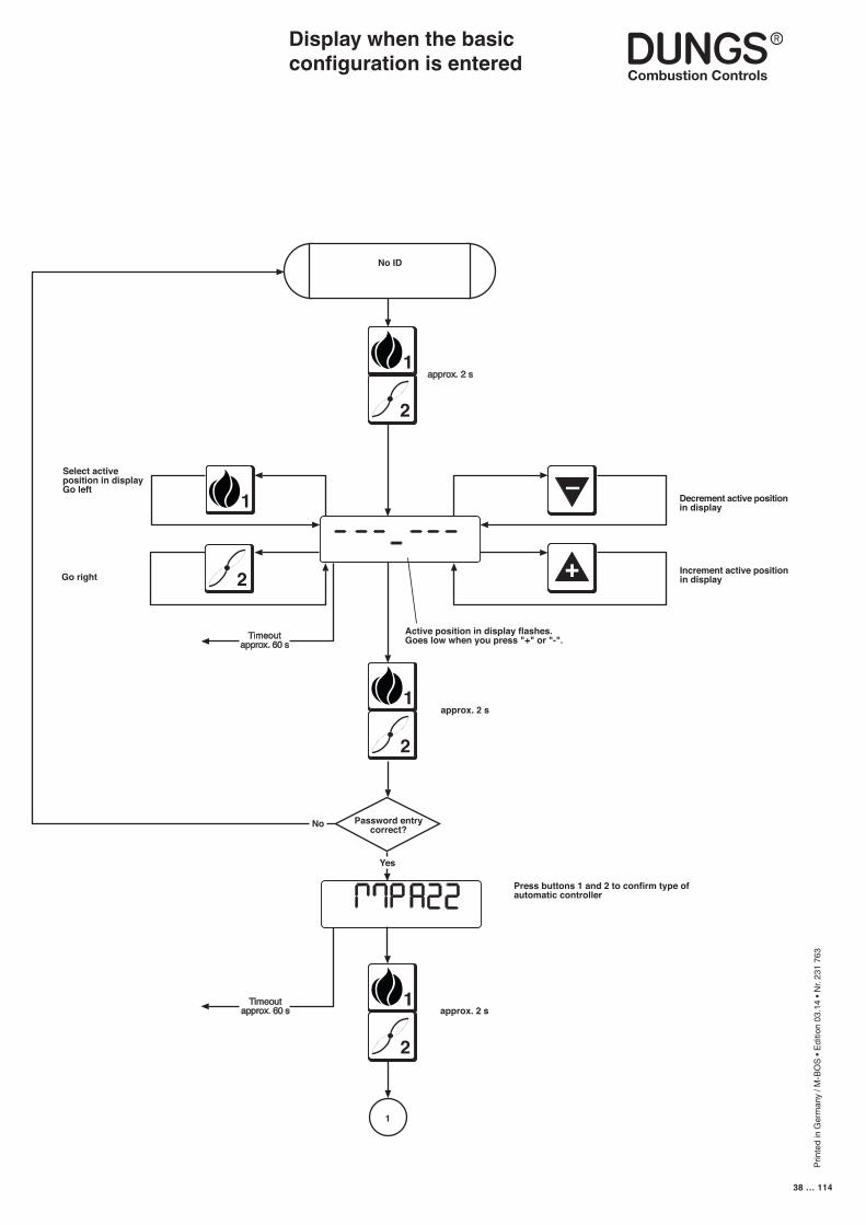
Prin
ted
in G
erm
any
/ M-B
OS
• Edi
tion
03.1
4 • N
r. 23
1 76
3
38 … 114
Display when the basic configuration is entered
–
Active position in display flashes.Goes low when you press "+" or "-".
Select activeposition in displayGo left
Yes
Go right
No
Decrement active positionin display
Increment active positionin display
approx. 2 s
approx. 2 s
Press buttons 1 and 2 to confirm type ofautomatic controller
+2
1
2
1
No ID
Password entrycorrect?
2
1
2
1
1
Timeoutapprox. 60 s
Timeoutapprox. 60 s
approx. 2 s

Prin
ted
in G
erm
any
/ M-B
OS
• Edi
tion
03.1
4 • N
r. 23
1 76
3
39 … 114
Display when the basic configuration is entered
Empty sh
eet
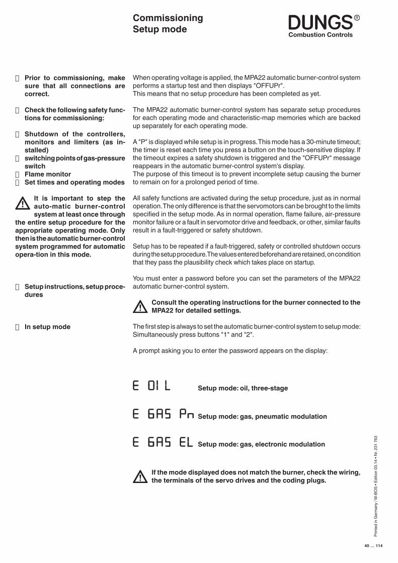
Prin
ted
in G
erm
any
/ M-B
OS
• Edi
tion
03.1
4 • N
r. 23
1 76
3
40 … 114
When operating voltage is applied, the MPA22 automatic burner-control system performs a startup test and then displays "OFFUPr". This means that no setup procedure has been completed as yet.
The MPA22 automatic burner-control system has separate setup procedures for each operating mode and characteristic-map memories which are backed up separately for each operating mode.
A "P" is displayed while setup is in progress. This mode has a 30-minute timeout; the timer is reset each time you press a button on the touch-sensitive display. If the timeout expires a safety shutdown is triggered and the "OFFUPr" message reappears in the automatic burner-control system's display.The purpose of this timeout is to prevent incomplete setup causing the burner to remain on for a prolonged period of time.
All safety functions are activated during the setup procedure, just as in normal operation. The only difference is that the servomotors can be brought to the limits specified in the setup mode. As in normal operation, flame failure, air-pressure monitor failure or a fault in servomotor drive and feedback, or other, similar faults result in a fault-triggered or safety shutdown.
Setup has to be repeated if a fault-triggered, safety or controlled shutdown occurs during the setup procedure. The values entered beforehand are retained, on condition that they pass the plausibility check which takes place on startup.
You must enter a password before you can set the parameters of the MPA22 automatic burner-control system.
Consult the operating instructions for the burner connected to the MPA22 for detailed settings.
The first step is always to set the automatic burner-control system to setup mode: Simultaneously press buttons "1" and "2".
A prompt asking you to enter the password appears on the display:
CommissioningSetup mode
■ Prior to commissioning, make sure that all connections are correct.
■ Check the following safety func-tions for commissioning:
■ Shutdown of the controllers, monitors and limiters (as in-stalled)
■ switching points of gas-pressure switch
■ Flame monitor■ Set times and operating modes
It is important to step the auto-matic burner-control system at least once through
the entire setup procedure for the appropriate operating mode. Only then is the automatic burner-control system programmed for automatic opera-tion in this mode.
■ Setup instructions, setup proce-dures
■ In setup mode
Setup mode: oil, three-stage
Setup mode: gas, pneumatic modulation
Setup mode: gas, electronic modulation
If the mode displayed does not match the burner, check the wiring, the terminals of the servo drives and the coding plugs.
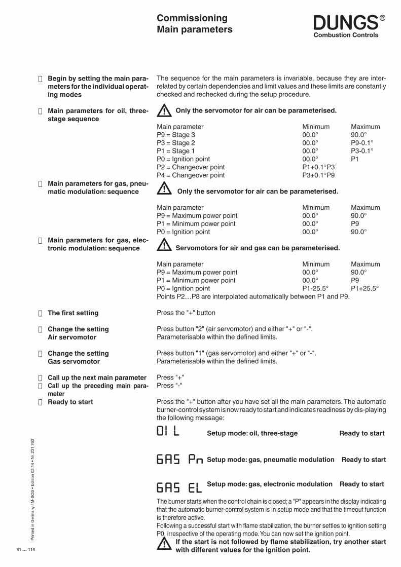
Prin
ted
in G
erm
any
/ M-B
OS
• Edi
tion
03.1
4 • N
r. 23
1 76
3
41 … 114
The sequence for the main parameters is invariable, because they are inter-related by certain dependencies and limit values and these limits are constantly checked and rechecked during the setup procedure.
Only the servomotor for air can be parameterised.
Main parameter Minimum Maximum P9 = Stage 3 00.0° 90.0°P3 = Stage 2 00.0° P9-0.1°P1 = Stage 1 00.0° P3-0.1°P0 = Ignition point 00.0° P1P2 = Changeover point P1+0.1° P3P4 = Changeover point P3+0.1° P9
Only the servomotor for air can be parameterised.
Main parameter Minimum MaximumP9 = Maximum power point 00.0° 90.0°P1 = Minimum power point 00.0° P9P0 = Ignition point 00.0° 90.0°
Servomotors for air and gas can be parameterised.
Main parameter Minimum MaximumP9 = Maximum power point 00.0° 90.0°P1 = Minimum power point 00.0° P9P0 = Ignition point P1-25.5° P1+25.5°Points P2…P8 are interpolated automatically between P1 and P9.
Press the "+" button
Press button "2" (air servomotor) and either "+" or "-".Parameterisable within the defined limits.
Press button "1" (gas servomotor) and either "+" or "-".Parameterisable within the defined limits.
Press "+"Press "-"
Press the "+" button after you have set all the main parameters. The automatic burner-control system is now ready to start and indicates readiness by dis-playing the following message:
The burner starts when the control chain is closed; a "P" appears in the display indicating that the automatic burner-control system is in setup mode and that the timeout function is therefore active.Following a successful start with flame stabilization, the burner settles to ignition setting P0, irrespective of the operating mode. You can now set the ignition point.
If the start is not followed by flame stabilization, try another start with different values for the ignition point.
■ Begin by setting the main para-meters for the individual operat-ing modes
■ Main parameters for oil, three-stage sequence
■ Main parameters for gas, pneu-matic modulation: sequence
■ Main parameters for gas, elec-tronic modulation: sequence
■ The first setting
■ Change the setting Air servomotor
■ Change the setting Gas servomotor
■ Call up the next main parameter■ Call up the preceding main para-
meter■ Ready to start
CommissioningMain parameters
Setup mode: gas, electronic modulation Ready to start
Setup mode: gas, pneumatic modulation Ready to start
Setup mode: oil, three-stage Ready to start
Prin
ted
in G
erm
any
/ M-B
OS
• Edi
tion
03.1
4 • N
r. 23
1 76
3
42 … 114
Setup modeGas firing, electronic modulation
The controller automatically goes to standby status if the automatic burner-control system has not been programmed. In the unprogrammed state, the automatic burner-control system remains on standby. Unprogrammed means that the characteristic has not been fully programmed.Once a valid characteristic has been programmed and the automatic burner-control system detects the presence of the corresponding components when it starts up, the burner starts as soon as the control chain and GWmax are closed.
If you want to correct a characteristic or ignition point P0 without recalculating all other points as well, you can access setup mode by simultaneously pressing the "+" and "-" buttons.
Simultaneously press the "1" and "2" buttons if you want to enter the full setup mode. The "P" symbol always appears in the display to indicate that setup mode is activated. If you do not press a button in setup mode before the timeout expires, setup mode is exited automatically and a RESTART is performed.
■ The burner must be in standby status, otherwise you cannot access the setup mode
■ Changing a characteristic de-fined beforehand
■ Accessing setup mode
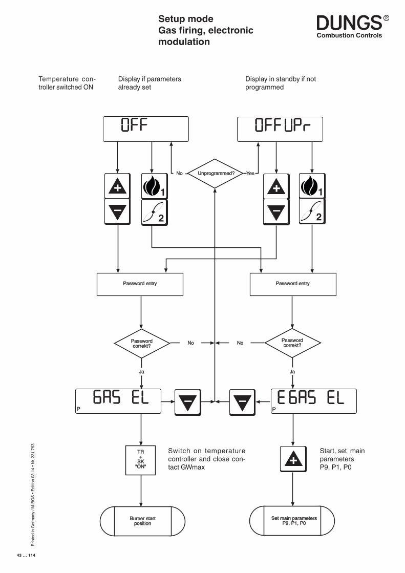
Prin
ted
in G
erm
any
/ M-B
OS
• Edi
tion
03.1
4 • N
r. 23
1 76
3
43 … 114
2
Unprogrammed?No Yes
Password entry Password entry
Passwordcorrekt?
Passwordcorrekt?No
Ja Ja
TR+
SK"ON"
No
Burner startposition
Set main parametersP9, P1, P0
1+
–
+
–
1
2
PP
– –
+
Setup modeGas firing, electronic modulation
Display if parameters already set
Display in standby if not programmed
Switch on temperature controller and close con-tact GWmax
Start, set main parameters P9, P1, P0
Temperature con-troller switched ON
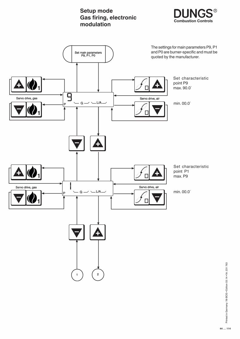
Prin
ted
in G
erm
any
/ M-B
OS
• Edi
tion
03.1
4 • N
r. 23
1 76
3
44 … 114
P G L/A
Set main parametersP9, P1, P0
–
+
–
+
21
P G L/AServo drive, airServo drive, gas
1+
1
–
Servo drive, gas
1+
1
–
Servo drive, air
� +
�
–
� +
�
–
Setup modeGas firing, electronic modulation
The settings for main parameters P9, P1 and P0 are burner-specific and must be quoted by the manufacturer.
min. 00.0°
Set characteristic point P9max. 90.0°
Set characteristic point P1 max. P9
min. 00.0°
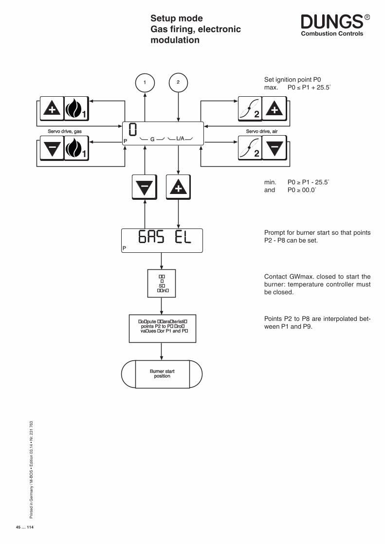
Prin
ted
in G
erm
any
/ M-B
OS
• Edi
tion
03.1
4 • N
r. 23
1 76
3
45 … 114
GServo drive, air
P L/A
P
–
+
Servo drive, gas
Burner startposition
1+
1
–
2
–
2 +
21
���
S���n�
�o�pute ��ara�teristi�points P2 to P� �ro�va�ues �or P1 and P�
Setup modeGas firing, electronic modulation
Set ignition point P0max. P0 ≤ P1 + 25.5°
Prompt for burner start so that points P2 - P8 can be set.
Contact GWmax. closed to start the burner: temperature controller must be closed.
Points P2 to P8 are interpolated bet-ween P1 and P9.
min. P0 ≥ P1 - 25.5°
and P0 ≥ 00.0°
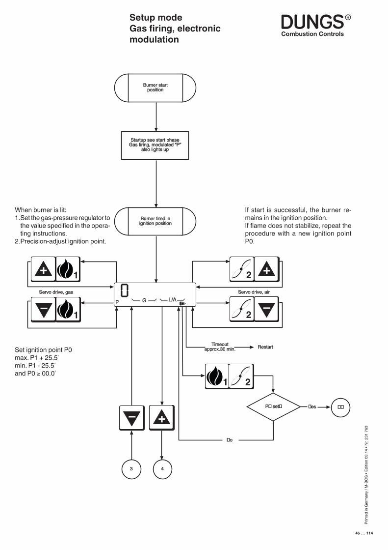
Prin
ted
in G
erm
any
/ M-B
OS
• Edi
tion
03.1
4 • N
r. 23
1 76
3
46 … 114
Burner startposition
Burner fired inignition position
Timeoutapprox.30 min. Restart
Servo drive, gas
1+
1
–
Servo drive, air
P G L/A
2 +
2
–
3
Startup see start phaseGas firing, modulated “P”
also lights up
–
4
1 2
P� set� �es ��
�o
+
Setup modeGas firing, electronic modulation
If start is successful, the burner re-mains in the ignition position.If flame does not stabilize, repeat the procedure with a new ignition point P0.
When burner is lit:1. Set the gas-pressure regulator to
the value specified in the opera-ting instructions.
2. Precision-adjust ignition point.
Set ignition point P0max. P1 + 25.5°
min. P1 - 25.5°
and P0 ≥ 00.0°
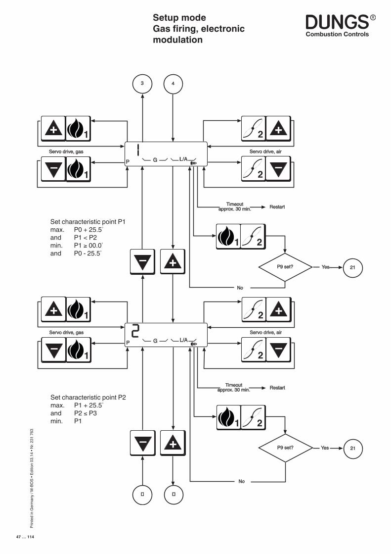
Prin
ted
in G
erm
any
/ M-B
OS
• Edi
tion
03.1
4 • N
r. 23
1 76
3
47 … 114
Timeoutapprox. 30 min. Restart
Servo drive, gas
1+
1
–
Servo drive, air
P G L/A
2 +
2
–
1 2
P9 set? Yes 21
No
3 4
Timeoutapprox. 30 min. Restart
Servo drive, gas
1+
1
–
Servo drive, air
P G L/A
2 +
2
–
–
1 2
P9 set? Yes 21
No
+
–
� �
+
Setup modeGas firing, electronic modulation
Set characteristic point P1 max. P0 + 25.5°
and P1 < P2min. P1 ≥ 00.0°
and P0 - 25.5°
Set characteristic point P2max. P1 + 25.5°
and P2 ≤ P3min. P1
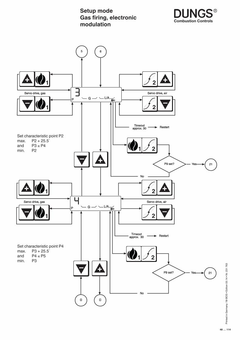
Prin
ted
in G
erm
any
/ M-B
OS
• Edi
tion
03.1
4 • N
r. 23
1 76
3
48 … 114
Timeoutapprox. 30 Restart
Servo drive, gas
1+
1
–
Servo drive, air
P G L/A
2 +
2
–
1 2
P9 set? Yes 21
No
5 6
–
Timeoutapprox. 30 Restart
Servo drive, gas
1+
1
–
Servo drive, air
P G L/A
2 +
2
–
1 2
P9 set? Yes 21
No
–
� �
+
+
Setup modeGas firing, electronic modulation
Set characteristic point P2max. P2 + 25.5°
and P3 ≤ P4min. P2
Set characteristic point P4max. P3 + 25.5°
and P4 ≤ P5min. P3
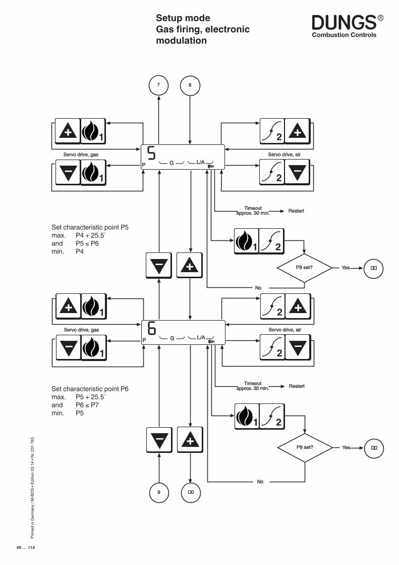
Prin
ted
in G
erm
any
/ M-B
OS
• Edi
tion
03.1
4 • N
r. 23
1 76
3
49 … 114
Timeoutapprox. 30 min. Restart
Servo drive, gas
1+
1
–
Servo drive, air
P G L/A
2 +
2
–
1 2
P9 set?
No
7 8
–
Yes ��
Timeoutapprox. 30 min. Restart
1+
1
–
Servo drive, air
P G L/A
2 +
2
–
–
1 2
P9 set? Yes ��
No
9 �0
Servo drive, gas
+
+
Setup modeGas firing, electronic modulation
Set characteristic point P5max. P4 + 25.5°
and P5 ≤ P6min. P4
Set characteristic point P6max. P5 + 25.5°
and P6 ≤ P7min. P5
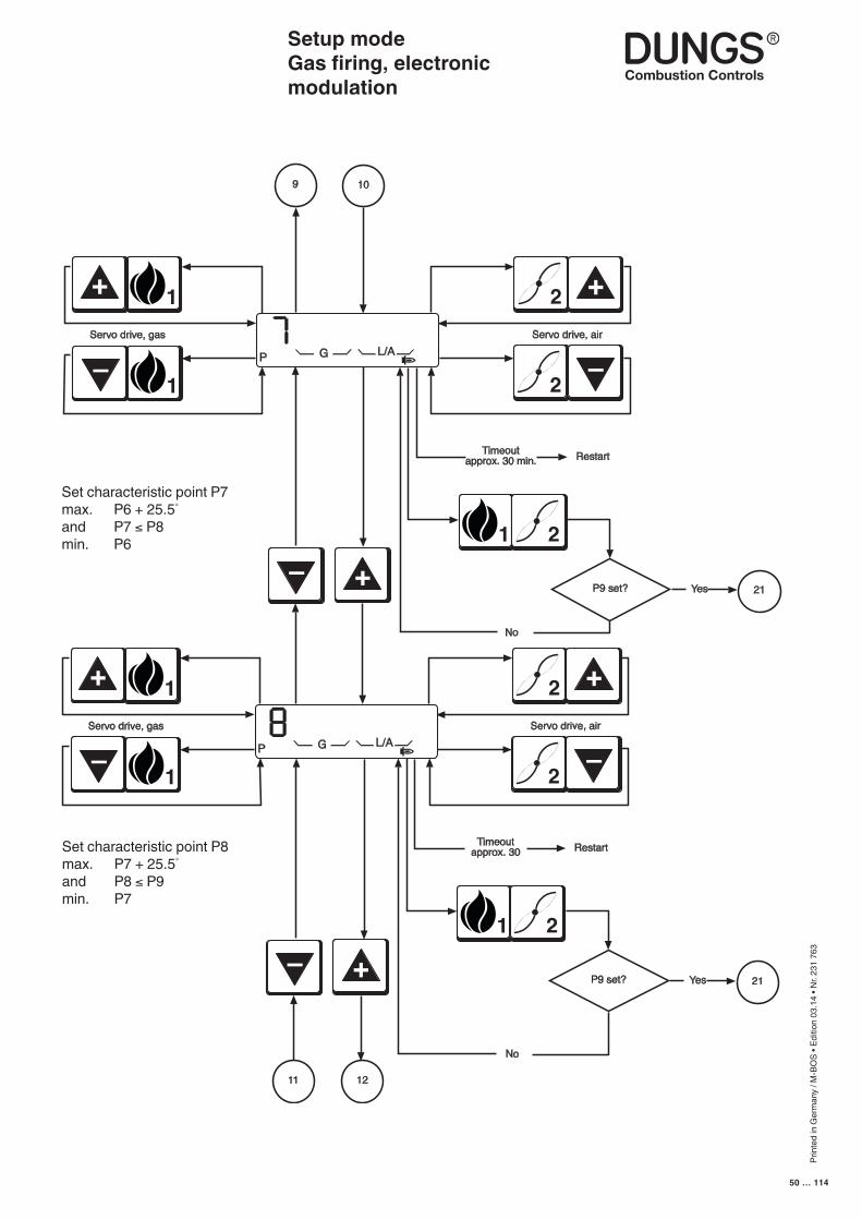
Prin
ted
in G
erm
any
/ M-B
OS
• Edi
tion
03.1
4 • N
r. 23
1 76
3
50 … 114
Timeoutapprox. 30 min. Restart
Servo drive, gas
1+
1
–
Servo drive, air
P G L/A
2 +
2
–
1 2
P9 set? Yes 21
No
9 10
–
Timeoutapprox. 30 Restart
Servo drive, gas
1+
1
–
Servo drive, air
P G L/A
2 +
2
–
1 2
P9 set? Yes 21
No
–
11 12
+
+
Setup modeGas firing, electronic modulation
Set characteristic point P7max. P6 + 25.5°
and P7 ≤ P8min. P6
Set characteristic point P8max. P7 + 25.5°
and P8 ≤ P9min. P7
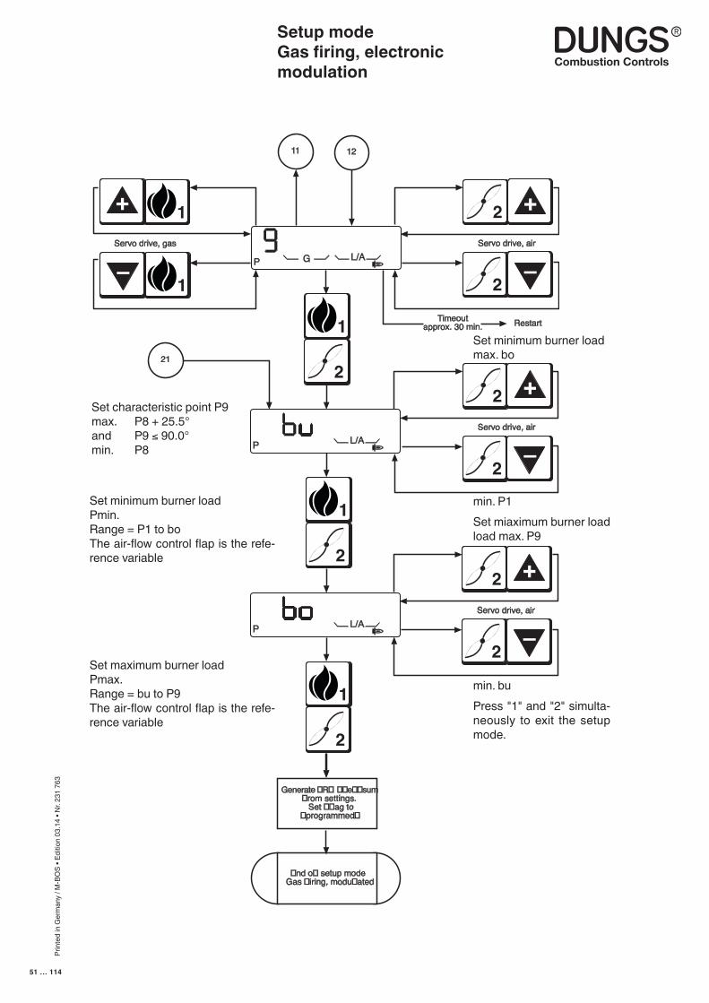
Prin
ted
in G
erm
any
/ M-B
OS
• Edi
tion
03.1
4 • N
r. 23
1 76
3
51 … 114
Timeoutapprox. 30 min. Restart
Servo drive, gas
1+
1
–
Servo drive, air
2 +
2
–
1211
1
2
P G L/A
P L/A
1
2
P L/AServo drive, air
2 +
2
–
1
2
�nd o� setup modeGas �iring, modu�ated
Generate �R� ��e��sum�rom settings.
Set ��ag to�programmed�
21
Servo drive, air
2 +
2
–
Setup modeGas firing, electronic modulation
Set characteristic point P9max. P8 + 25.5°and P9 ≤ 90.0°min. P8
Set minimum burner loadPmin.Range = P1 to boThe air-flow control flap is the refe-rence variable
Set maximum burner loadPmax.Range = bu to P9The air-flow control flap is the refe-rence variable
Set minimum burner loadmax. bo
Set miaximum burner load load max. P9
min. P1
Press "1" and "2" simulta-neously to exit the setup mode.
min. bu
Prin
ted
in G
erm
any
/ M-B
OS
• Edi
tion
03.1
4 • N
r. 23
1 76
3
52 … 114
Setup modeGas firing, pneumatic modulation
The controller automatically goes to standby status if the automatic burner-control system has not been programmed. In the unprogrammed state, the automatic burner-control system remains on standby. Unprogrammed means that the working point has not been fully programmed. Once valid working points have been programmed and the automatic burner-control system detects the presence of the corresponding components when it starts up, the burner starts as soon as the control chain and GWmax are closed.
If progamming has been completed and you want to correct points such as the ignition load P0, low load P1 or high load P9 in operation, press the "+" and "-" buttons simultaneously to access setup mode.
Simultaneously press the "1" and "2" buttons if you want to enter the full setup mode. The "P" symbol always appears in the display to indicate that setup mode is activated. If you do not press a button in setup mode before the timeout expires, setup mode is exited automatically and a RESTART is performed.
■ The burner must be in standby status, otherwise you cannot access the setup mode
■ Changing points defined before-hand
■ Accessing setup mode
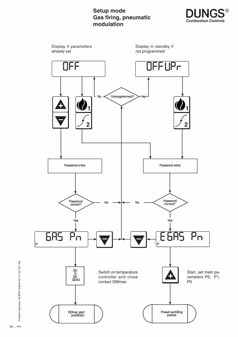
Prin
ted
in G
erm
any
/ M-B
OS
• Edi
tion
03.1
4 • N
r. 23
1 76
3
53 … 114
+
–
– –
+
hl,m3
1
2
Unprogrammed?No Yes
1
2
Password entry Password entry
Passwordcorrect?
Passwordcorrect?No
Yes Yes
���
����n�
No
P P
��rner startpos�t�on
Preset wor��ngpo�nts
Setup modeGas firing, pneumatic modulation
Start, set main pa-rameters P9, P1, P0
Switch on temperature controller and close contact GWmax
Display if parameters already set
Display in standby if not programmed
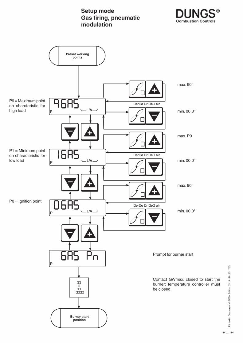
Prin
ted
in G
erm
any
/ M-B
OS
• Edi
tion
03.1
4 • N
r. 23
1 76
3
54 … 114
Setup modeGas firing, pneumatic modulation
–
–
+
+
–
+
Burner startposition
P L/A
Preset workingpoints
P L/A
P L/A
P
er o ri e air
+
–
er o ri e air
+
–
er o ri e air
+
–
���
������
max. 90°
min. 00,0°
max. P9
min. 00,0°
max. 90°
min. 00,0°
Prompt for burner start
Contact GWmax. closed to start the burner: temperature controller must be closed.
P0 = Ignition point
P1 = Minimum point on characteristic for low load
P9 = Maximum point on charcteristic for high load
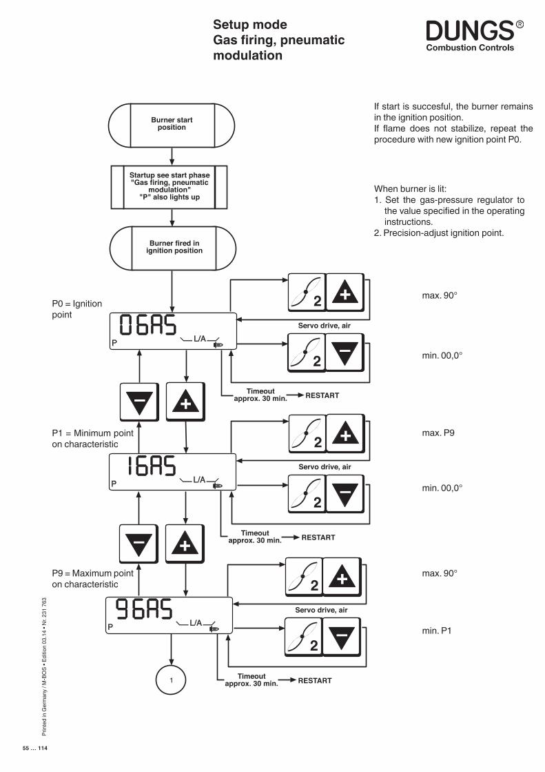
Prin
ted
in G
erm
any
/ M-B
OS
• Edi
tion
03.1
4 • N
r. 23
1 76
3
55 … 114
Setup modeGas firing, pneumatic modulation
–
+
–
+
Burner startposition
Startup see start phase"Gas firing, pneumatic
modulation""P" also lights up
Burner fired inignition position
RESTARTTimeoutapprox. 30 min.
P L/AServo drive, air
2 +
2
–
1
P L/A
Timeoutapprox. 30 min. RESTART
Servo drive, air
2 +
2
–
P L/A
Timeoutapprox. 30 min. RESTART
Servo drive, air
2 +
2
–If start is succesful, the burner remains in the ignition position.If flame does not stabilize, repeat the procedure with new ignition point P0.
When burner is lit:1. Set the gas-pressure regulator to
the value specified in the operating instructions.
2. Precision-adjust ignition point.
max. 90°
min. 00,0°
max. P9
min. 00,0°
max. 90°
min. P1
P0 = Ignitionpoint
P1 = Minimum point on characteristic
P9 = Maximum point on characteristic
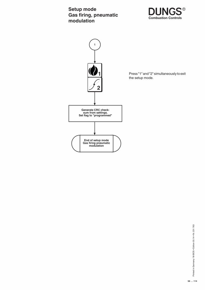
Prin
ted
in G
erm
any
/ M-B
OS
• Edi
tion
03.1
4 • N
r. 23
1 76
3
56 … 114
Setup modeGas firing, pneumatic modulation
1
Generate CRC check-sum from settings.
Set flag to "programmed"
End of setup modeGas firing pneumatic
modulation
1
2
Press "1" and "2" simultaneously to exit the setup mode.
Prin
ted
in G
erm
any
/ M-B
OS
• Edi
tion
03.1
4 • N
r. 23
1 76
3
57 … 114
The controller automatically goes to standby status if the automatic burner-control system has not been programmed. In the unprogrammed state, the automatic burner-control system remains on standby. Unprogrammed means that the working point has not been fully programmed.Once valid working points have been programmed and the automatic burner-control system detects the presence of the corresponding components when it starts up, the burner starts as soon as the control chain and GWmax are closed.
If progamming has been completed and you want to correct points such as the the first stage P1, the second stage P3, the third stage P9 or the changeover points P2 and P4 in operation, press the "+" and "-" buttons simultaneously to access setup mode.
Simultaneously press the "1" and "2" buttons if you want to enter the full setup mode. The "P" symbol always appears in the display to indicate that setup mode is activated. If you do not press a button in setup mode before the timeout expires, setup mode is exited automatically and a RESTART is performed.
Setup modeOil firing, three stage
■ The burner must be in standby status, otherwise you cannot access the setup mode
■ Changing points defined before-hand
■ Accessing setup mode
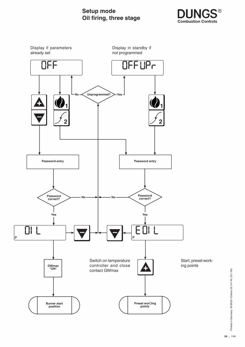
Prin
ted
in G
erm
any
/ M-B
OS
• Edi
tion
03.1
4 • N
r. 23
1 76
3
58 … 114
1
2
Unprogrammed?No Yes
1
2
Password entry Password entry
Passwordcorrect?
Passwordcorrect?No
Yes Yes
+
–
GWmax"ON"
No
Burner startposition
Preset wor�ingpoints
P P
– –
+
Setup modeOil firing, three stage
Start, preset work-ing points
Switch on temperature controller and close contact GWmax
Display if parameters already set
Display in standby if not programmed
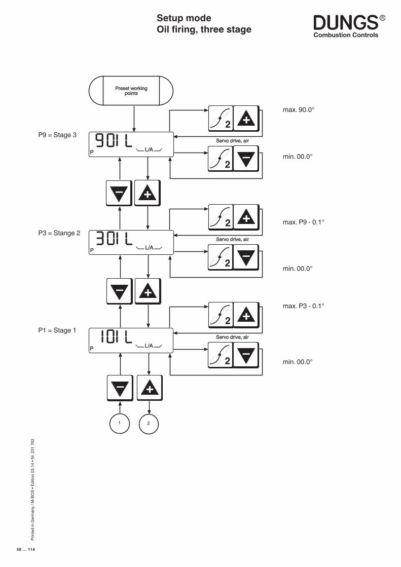
Prin
ted
in G
erm
any
/ M-B
OS
• Edi
tion
03.1
4 • N
r. 23
1 76
3
59 … 114
P9 = Stage 3
P3 = Stange 2
P1 = Stage 1
max. 90.0°
min. 00.0°
max. P9 - 0.1°
min. 00.0°
max. P3 - 0.1°
Setup modeOil firing, three stage
Servo drive, air
2 +
2
–
Preset workingpoints
P L/A
1 2
Servo drive, air
2 +
2
–
Servo drive, air
2 +
2
–
P L/A
P L/A
–
+
–+
–
+
min. 00.0°
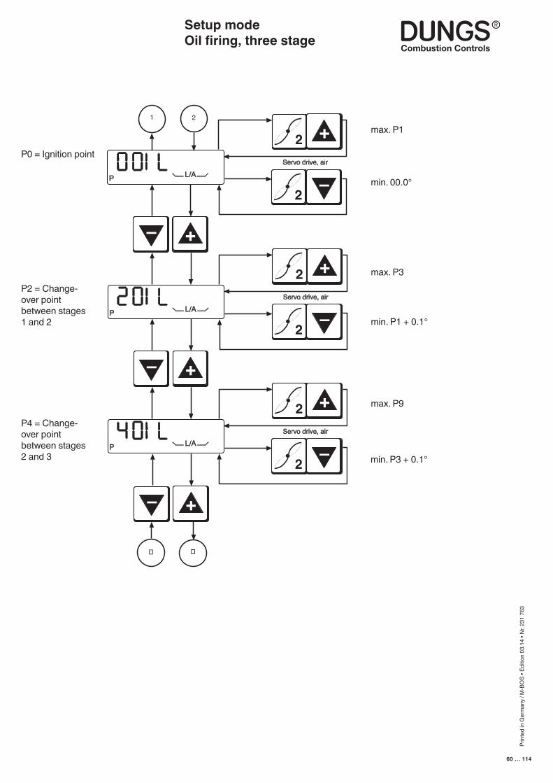
Prin
ted
in G
erm
any
/ M-B
OS
• Edi
tion
03.1
4 • N
r. 23
1 76
3
60 … 114
Servo drive, air
2 +
2
–P L/A
1 2
Servo drive, air
2 +
2
–P L/A
Servo drive, air
2 +
2
–P L/A
� �
–
+
–
+
–
+
max. P1
min. 00.0°
max. P3
min. P1 + 0.1°
min. P3 + 0.1°
max. P9
P0 = Ignition point
P2 = Change-over point between stages 1 and 2
P4 = Change-over point between stages 2 and 3
Setup modeOil firing, three stage
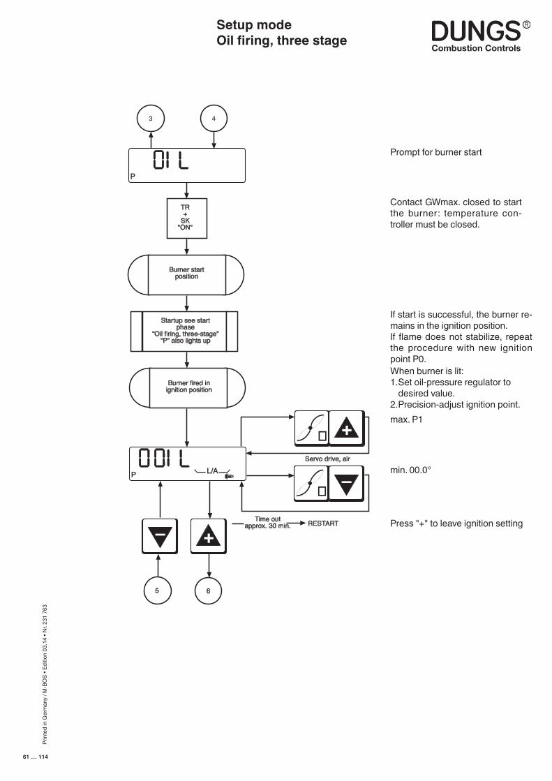
Prin
ted
in G
erm
any
/ M-B
OS
• Edi
tion
03.1
4 • N
r. 23
1 76
3
61 … 114
Prompt for burner start
Contact GWmax. closed to start the burner: temperature con-troller must be closed.
If start is successful, the burner re-mains in the ignition position.If flame does not stabilize, repeat the procedure with new ignition point P0.When burner is lit:1. Set oil-pressure regulator to
desired value.2. Precision-adjust ignition point.max. P1
min. 00.0°
Press "+" to leave ignition setting–
+
3
TR+
SK"ON"
Burner startposition
Startup see startphase
“Oil firing, three-stage”“P” also lights up
Burner fired inignition position
RESTARTTime outapprox. 30 min.
4
P
P L/A
5 6
Servo drive, air
� +
�
–
Setup modeOil firing, three stage
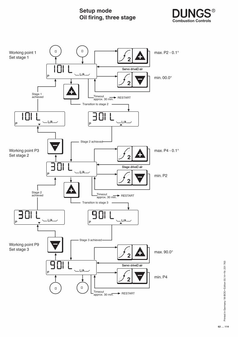
Prin
ted
in G
erm
any
/ M-B
OS
• Edi
tion
03.1
4 • N
r. 23
1 76
3
62 … 114
Transition to stage 2
Stage 1achieved
Stage 2 achieved
Timeoutapprox. 30 min. RESTART
P L/A
P L/A
P L/A
P L/A
� �
Servo drive� air
2 +
2
–
Stage drive� air
2 +
2
–
Timeoutapprox. 30 min. RESTART
Transition to stage 3
Stage 2achieved
Stage 3 achieved
Timeoutapprox. 30 min. RESTART
P L/A
P L/A
P L/A
��
Servo drive� air
2 +
2
–
+
–+
–
max. P2 - 0.1°
min. 00.0°
Working point 1Set stage 1
Working point P3 Set stage 2
max. P4 - 0.1°
min. P2
Setup modeOil firing, three stage
max. 90.0°
min. P4
Working point P9Set stage 3
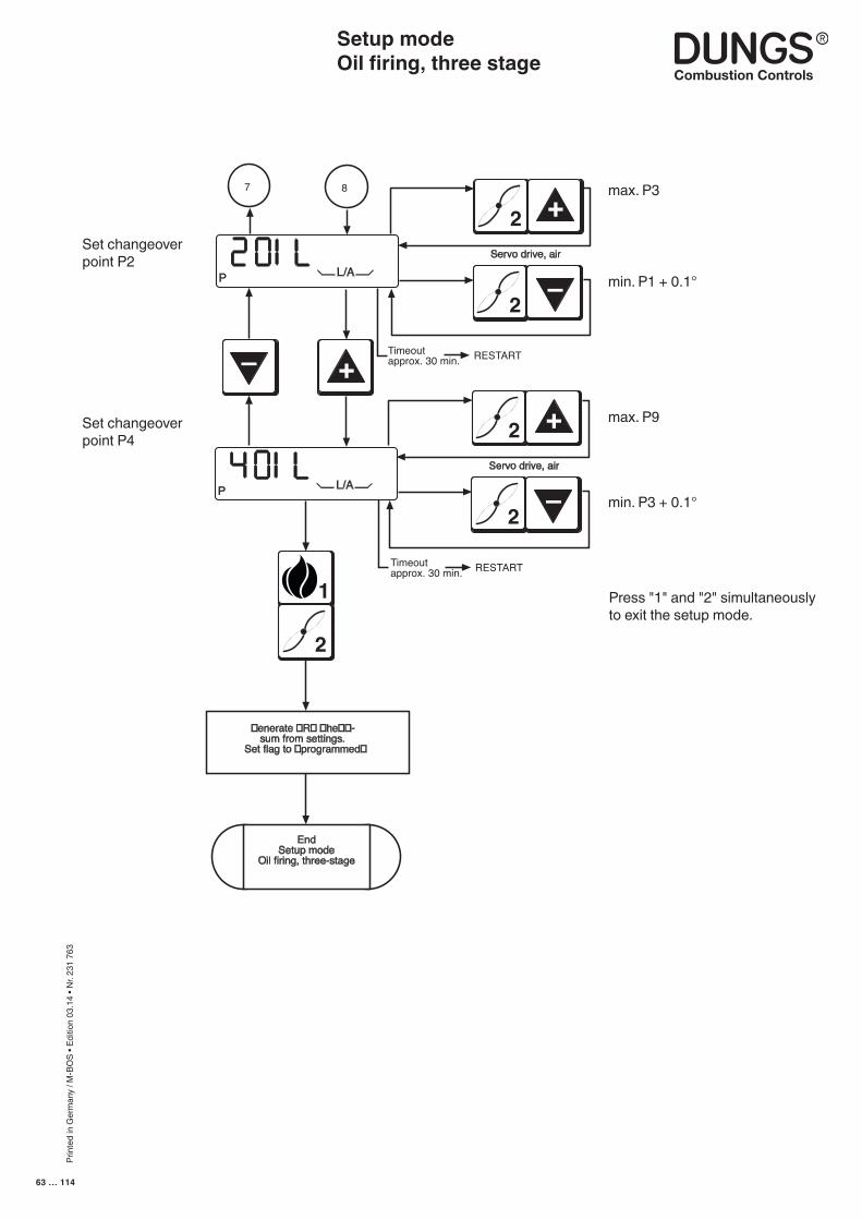
Prin
ted
in G
erm
any
/ M-B
OS
• Edi
tion
03.1
4 • N
r. 23
1 76
3
63 … 114
Timeoutapprox. 30 min. RESTART
7 8
P L/A
1
2
P L/A
Timeoutapprox. 30 min. RESTART
EndSetup mode
Oil firing, three-stage
Servo drive, air
2 +
2
–
Servo drive, air
2 +
2
–
�enerate �R� �he��-sum from settings.
Set flag to �programmed�
–
+
max. P3
min. P1 + 0.1°
Set changeoverpoint P2
max. P9
min. P3 + 0.1°
Setup modeOil firing, three stage
Set changeoverpoint P4
Press "1" and "2" simultaneously to exit the setup mode.

Prin
ted
in G
erm
any
/ M-B
OS
• Edi
tion
03.1
4 • N
r. 23
1 76
3
64 … 114
Display in operating modeGas firing, electronic modulationGas firing, pneumatic modulationDisplay in operating mode, gas firing with electronic modulation and gas firing with pneumatic modulation. If setup mode is activated, the "P" symbol also appears in the start phase.
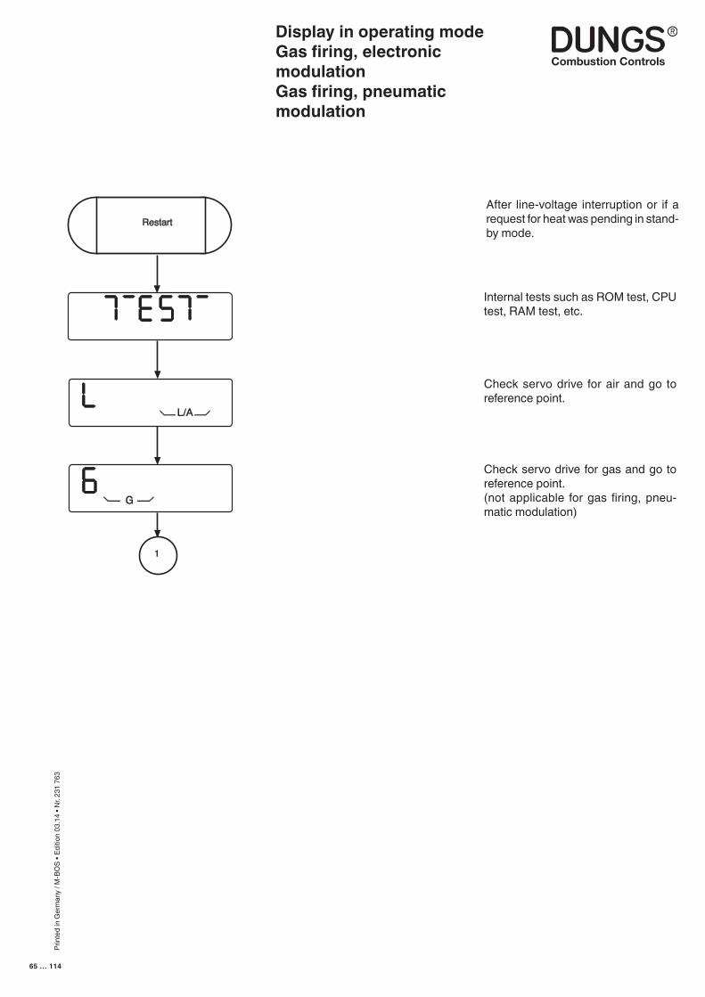
Prin
ted
in G
erm
any
/ M-B
OS
• Edi
tion
03.1
4 • N
r. 23
1 76
3
65 … 114
After line-voltage interruption or if a request for heat was pending in stand-by mode.
Internal tests such as ROM test, CPU test, RAM test, etc.
Check servo drive for air and go to reference point.
Check servo drive for gas and go to reference point.(not applicable for gas firing, pneu-matic modulation)
L/A
G
1
Restart
Display in operating modeGas firing, electronic modulationGas firing, pneumatic modulation
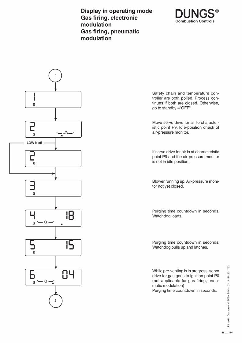
Prin
ted
in G
erm
any
/ M-B
OS
• Edi
tion
03.1
4 • N
r. 23
1 76
3
66 … 114
Safety chain and temperature con-troller are both polled. Process con-tinues if both are closed. Otherwise, go to standby =“OFF“.
Move servo drive for air to character-istic point P9. Idle-position check of air-pressure monitor.
If servo drive for air is at characteristic point P9 and the air-pressure monitor is not in idle position.
Blower running up. Air-pressure moni-tor not yet closed.
Purging time countdown in seconds. Watchdog loads.
While pre-venting is in progress, servo drive for gas goes to ignition point P0 (not applicable for gas firing, pneu-matic modulation)Purging time countdown in seconds.
Display in operating modeGas firing, electronic modulationGas firing, pneumatic modulation
Purging time countdown in seconds. Watchdog pulls up and latches.
S
S
S G
S
S
S L/A
1
LGW is off
S G
2
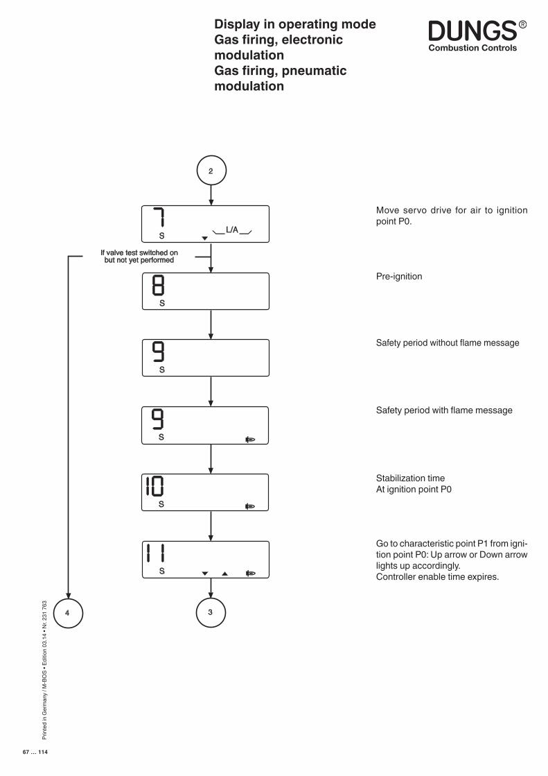
Prin
ted
in G
erm
any
/ M-B
OS
• Edi
tion
03.1
4 • N
r. 23
1 76
3
67 … 114
Move servo drive for air to ignition point P0.
Pre-ignition
Safety period without flame message
Safety period with flame message
Stabilization timeAt ignition point P0
Go to characteristic point P1 from igni-tion point P0: Up arrow or Down arrow lights up accordingly.Controller enable time expires.
Display in operating modeGas firing, electronic modulationGas firing, pneumatic modulation
S
If valve test switched onbut not yet performed
S
S
S
S
S
2
34
L/A
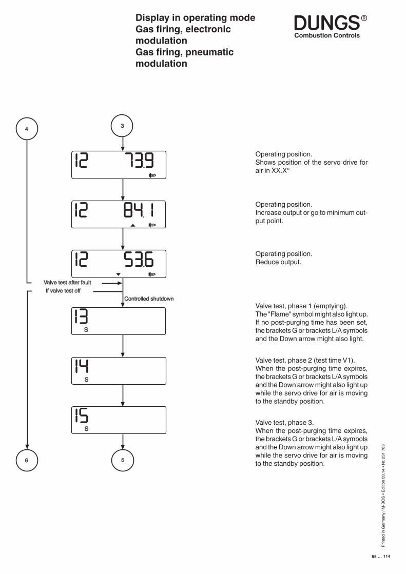
Prin
ted
in G
erm
any
/ M-B
OS
• Edi
tion
03.1
4 • N
r. 23
1 76
3
68 … 114
Operating position.Shows position of the servo drive for air in XX.X°
Operating position.Increase output or go to minimum out-put point.
Operating position.Reduce output.
Valve test, phase 1 (emptying).The "Flame" symbol might also light up. If no post-purging time has been set, the brackets G or brackets L/A symbols and the Down arrow might also light.
Valve test, phase 2 (test time V1).When the post-purging time expires, the brackets G or brackets L/A symbols and the Down arrow might also light up while the servo drive for air is moving to the standby position.
Valve test, phase 3.When the post-purging time expires, the brackets G or brackets L/A symbols and the Down arrow might also light up while the servo drive for air is moving to the standby position.
Valve test after faultIf valve test off
S
S
S
Controlled shutdown
4 3
6 5
Display in operating modeGas firing, electronic modulationGas firing, pneumatic modulation
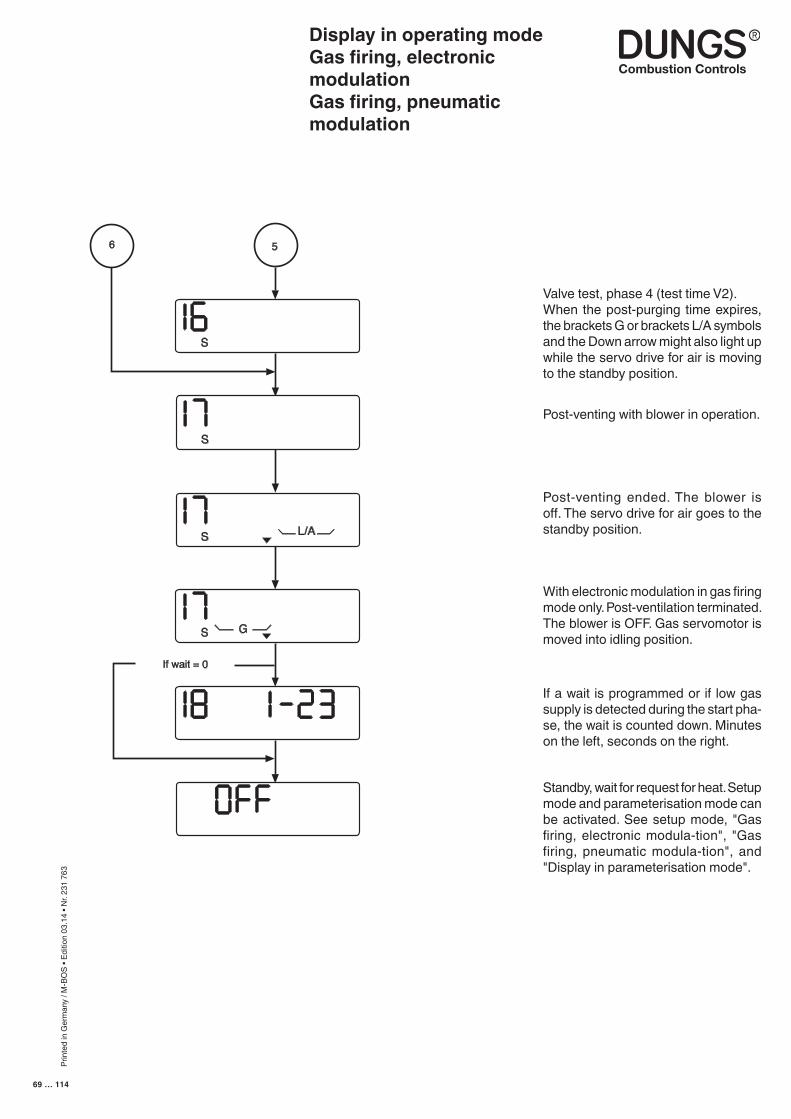
Prin
ted
in G
erm
any
/ M-B
OS
• Edi
tion
03.1
4 • N
r. 23
1 76
3
69 … 114
Valve test, phase 4 (test time V2).When the post-purging time expires, the brackets G or brackets L/A symbols and the Down arrow might also light up while the servo drive for air is moving to the standby position.
Post-venting with blower in operation.
Post-venting ended. The blower is off. The servo drive for air goes to the standby position.
With electronic modulation in gas firing mode only. Post-ventilation terminated. The blower is OFF. Gas servomotor is moved into idling position.
If a wait is programmed or if low gas supply is detected during the start pha-se, the wait is counted down. Minutes on the left, seconds on the right.
Standby, wait for request for heat. Setup mode and parameterisation mode can be activated. See setup mode, "Gas firing, electronic modula-tion", "Gas firing, pneumatic modula-tion", and "Display in parameterisation mode".
S
S
S G
If wait = 0
6 5
S L/A
Display in operating modeGas firing, electronic modulationGas firing, pneumatic modulation

Prin
ted
in G
erm
any
/ M-B
OS
• Edi
tion
03.1
4 • N
r. 23
1 76
3
70 … 114
Display in operating modeOil firing, three stage
Display in operating mode, oil firing, three stage.If setup mode is activated, the "P" symbol also appears in the start phase.
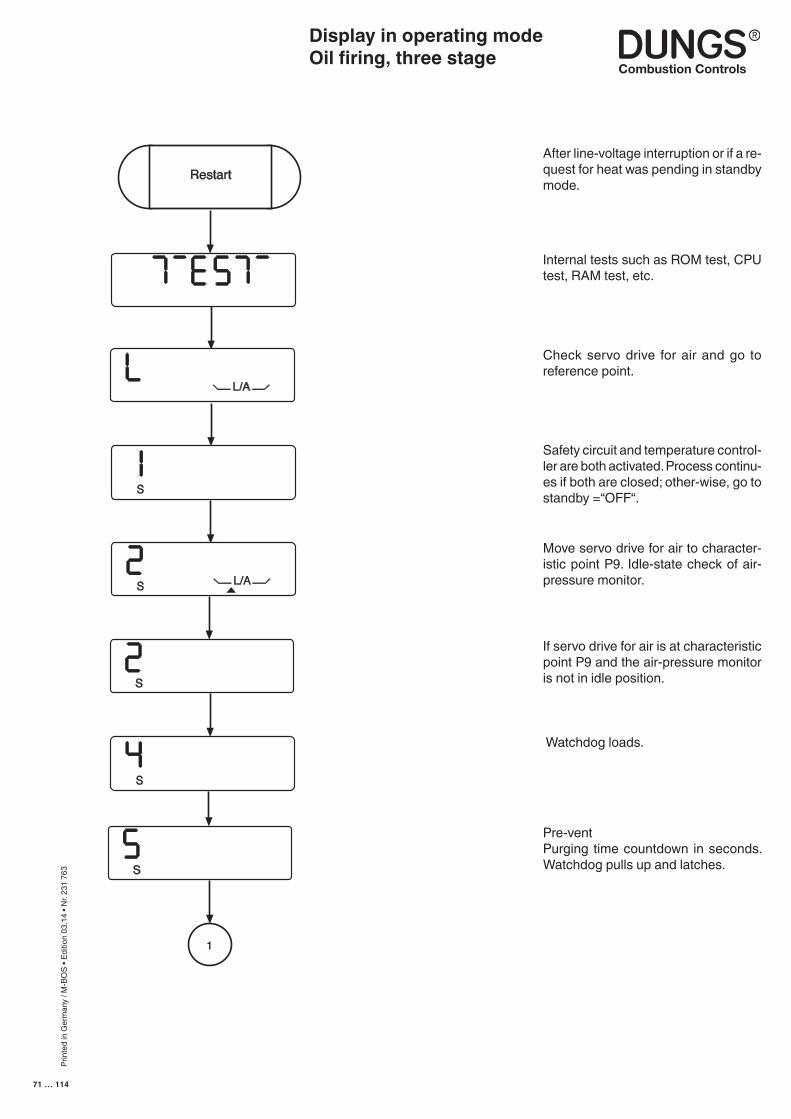
Prin
ted
in G
erm
any
/ M-B
OS
• Edi
tion
03.1
4 • N
r. 23
1 76
3
71 … 114
If servo drive for air is at characteristic point P9 and the air-pressure monitor is not in idle position.
Watchdog loads.
Pre-ventPurging time countdown in seconds. Watchdog pulls up and latches.
Internal tests such as ROM test, CPU test, RAM test, etc.
Check servo drive for air and go to reference point.
Safety circuit and temperature control-ler are both activated. Process continu-es if both are closed; other-wise, go to standby =“OFF“.
After line-voltage interruption or if a re-quest for heat was pending in standby mode.
Move servo drive for air to character-istic point P9. Idle-state check of air-pressure monitor.
Restart
L/A
S
S L/A
S
S
S
1
Display in operating modeOil firing, three stage
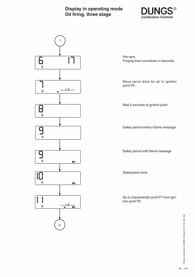
Prin
ted
in G
erm
any
/ M-B
OS
• Edi
tion
03.1
4 • N
r. 23
1 76
3
72 … 114
Move servo drive for air to ignition point P0.
Wait 2 seconds at ignition point
Display in operating modeOil firing, three stage
1
S
S L/A
S
S
S
S
S L/A
2
Pre-ventPurging time countdown in seconds.
Stabilization time
Go to characteristic point P1 from igni-tion point P0
Safety period without flame message
Safety period with flame message
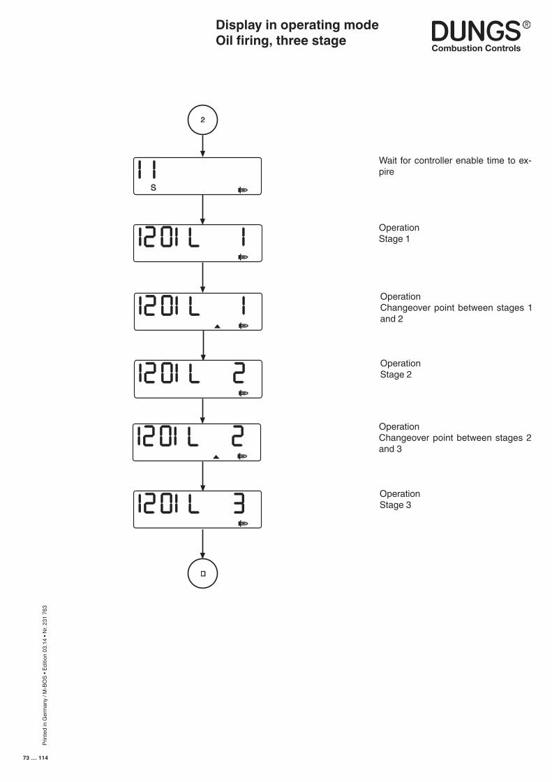
Prin
ted
in G
erm
any
/ M-B
OS
• Edi
tion
03.1
4 • N
r. 23
1 76
3
73 … 114
OperationChangeover point between stages 1 and 2
OperationStage 2
OperationChangeover point between stages 2 and 3
OperationStage 3
Wait for controller enable time to ex-pire
OperationStage 1
2
S
i
�
Display in operating modeOil firing, three stage
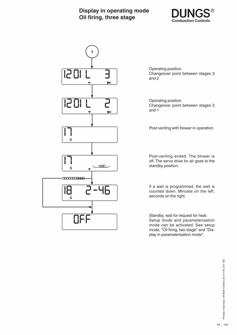
Prin
ted
in G
erm
any
/ M-B
OS
• Edi
tion
03.1
4 • N
r. 23
1 76
3
74 … 114
Display in operating modeOil firing, three stage
S
3
S
S ���
�����������
Operating position.Changeover point between stages 3 and 2
Post-venting with blower in operation.
Post-venting ended. The blower is off. The servo drive for air goes to the standby position.
If a wait is programmed, the wait is counted down. Minutes on the left, seconds on the right.
Standby, wait for request for heat.Setup mode and parameterisation mode can be activated. See setup mode, "Oil firing, two stage" and "Dis-play in parameterisation mode".
Operating position.Changeover point between stages 2 and 1
Prin
ted
in G
erm
any
/ M-B
OS
• Edi
tion
03.1
4 • N
r. 23
1 76
3
75 … 114
Display in information modeGas firing, electronic modulationGas firing, pneumatic modulation Oil firing, three stage
The information-mode display can be accessed only from the operating-mode display. It can be called up irrespective of burner status and provides infor-mation on:
Current counts for
• Fuel quantities• Operating hours• Starts
Information about:
• Software status• Date of production• Machine serial number
This display mode is exited after a 20-second timeout or if the readout is scrolled past the last item.
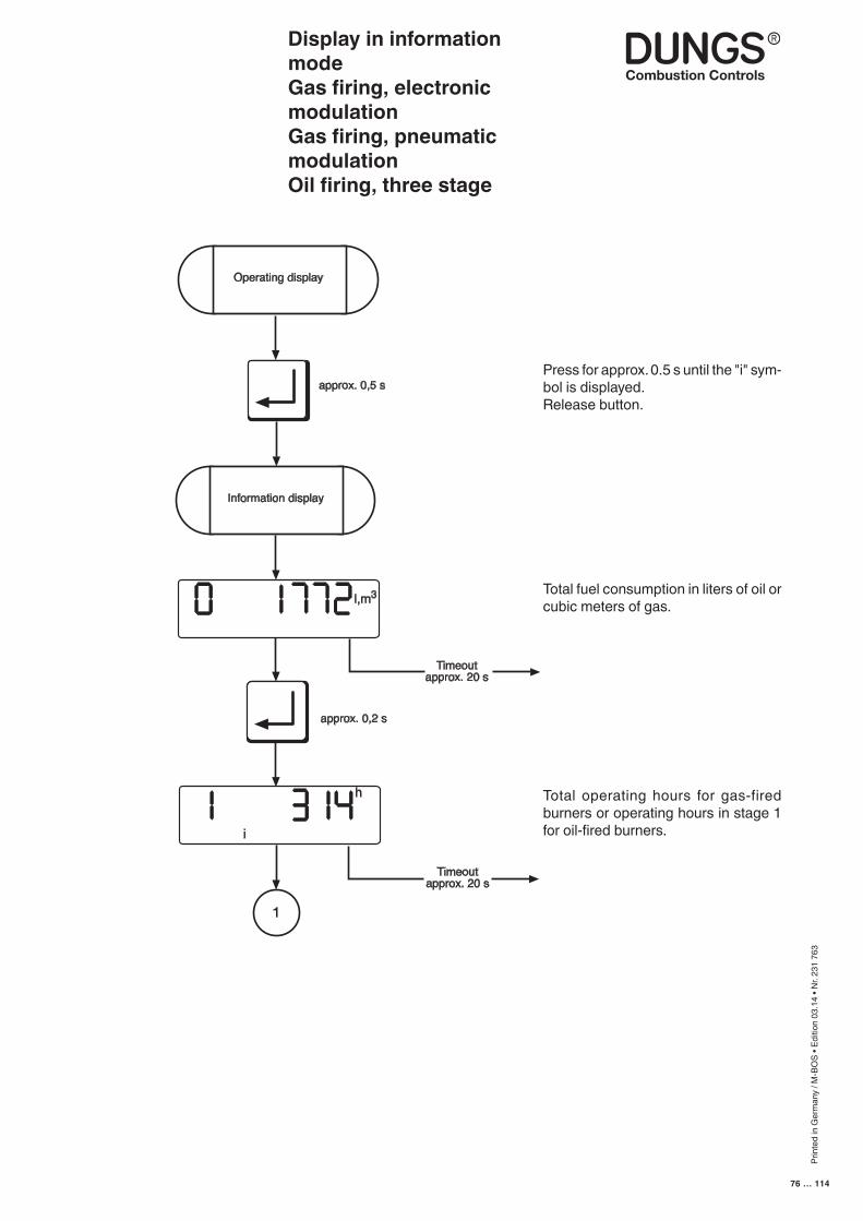
Prin
ted
in G
erm
any
/ M-B
OS
• Edi
tion
03.1
4 • N
r. 23
1 76
3
76 … 114
Display in information modeGas firing, electronic modulationGas firing, pneumatic modulation Oil firing, three stage
Press for approx. 0.5 s until the "i" sym-bol is displayed.Release button.
Total fuel consumption in liters of oil or cubic meters of gas.
Total operating hours for gas-fired burners or operating hours in stage 1 for oil-fired burners.
1
approx. 0,2 s
l,m3
Information display
Operating display
h
i
Timeoutapprox. 20 s
Timeoutapprox. 20 s
approx. 0,5 s
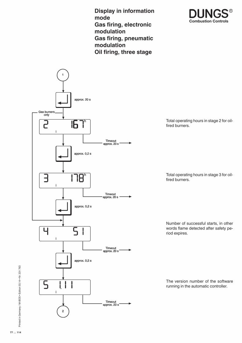
Prin
ted
in G
erm
any
/ M-B
OS
• Edi
tion
03.1
4 • N
r. 23
1 76
3
77 … 114
Display in information modeGas firing, electronic modulationGas firing, pneumatic modulation Oil firing, three stage
Number of successful starts, in other words flame detected after safety pe-riod expires.
The version number of the software running in the automatic controller.
1
approx. 0,2 s
h
i
Timeoutapprox. 20 s
i
h
2
i
i
Gas burnersonly
Timeoutapprox. 20 s
Timeoutapprox. 20 s
Timeoutapprox. 20 s
approx. 0,2 s
approx. 0,2 s
approx. 20 s
Total operating hours in stage 2 for oil-fired burners.
Total operating hours in stage 3 for oil-fired burners.
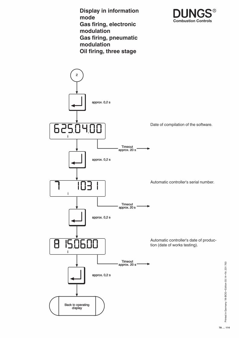
Prin
ted
in G
erm
any
/ M-B
OS
• Edi
tion
03.1
4 • N
r. 23
1 76
3
78 … 114
Automatic controller's serial number.
Automatic controller's date of produc-tion (date of works testing).
Display in information modeGas firing, electronic modulationGas firing, pneumatic modulation Oil firing, three stage
Timeoutapprox. 20 s
approx. 0,2 s
Timeoutapprox. 20 s
approx. 0,2 s
approx. 0,2 s
Timeoutapprox. 20 s
2
i
i
i
Back to operatingdisplay
approx. 0,2 s
Date of compilation of the software.
Prin
ted
in G
erm
any
/ M-B
OS
• Edi
tion
03.1
4 • N
r. 23
1 76
3
79 … 114
Display in service modeGas firing, electronic modulation
The service display can be called irrespective of the burner status and provides information on the characteristic stored in the EEPROM. The following data are displayed:
- The characteristic points P0 - P9- The last 6 error messages- The test times of the valve testing system - Flame quality- The e-BUS address- The switch position of the valve testing system- The limits of the modulation range- Controller address- The controller enable time
This display mode is exited after a 20-second timeout or if the readout is scrolled past the last item.
■ The service-mode display can be accessed only from the operat-ing-mode display.
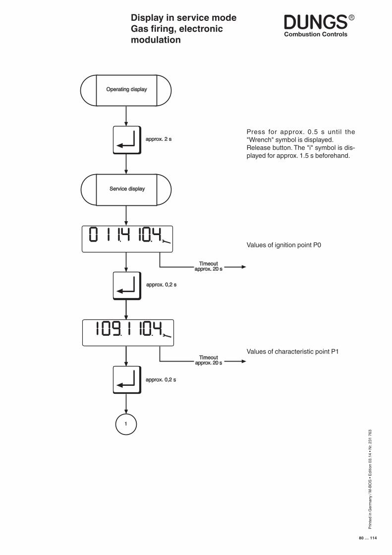
Prin
ted
in G
erm
any
/ M-B
OS
• Edi
tion
03.1
4 • N
r. 23
1 76
3
80 … 114
Display in service modeGas firing, electronic modulation
Press for approx. 0.5 s until the "Wrench" symbol is displayed.Release button. The "i" symbol is dis-played for approx. 1.5 s beforehand.
Values of ignition point P0
Values of characteristic point P1
N
approx. 0,2 s
approx. 0,2 s
Timeoutapprox. 20 s
Timeoutapprox. 20 s
1
Service display
Operating display
approx. 2 s
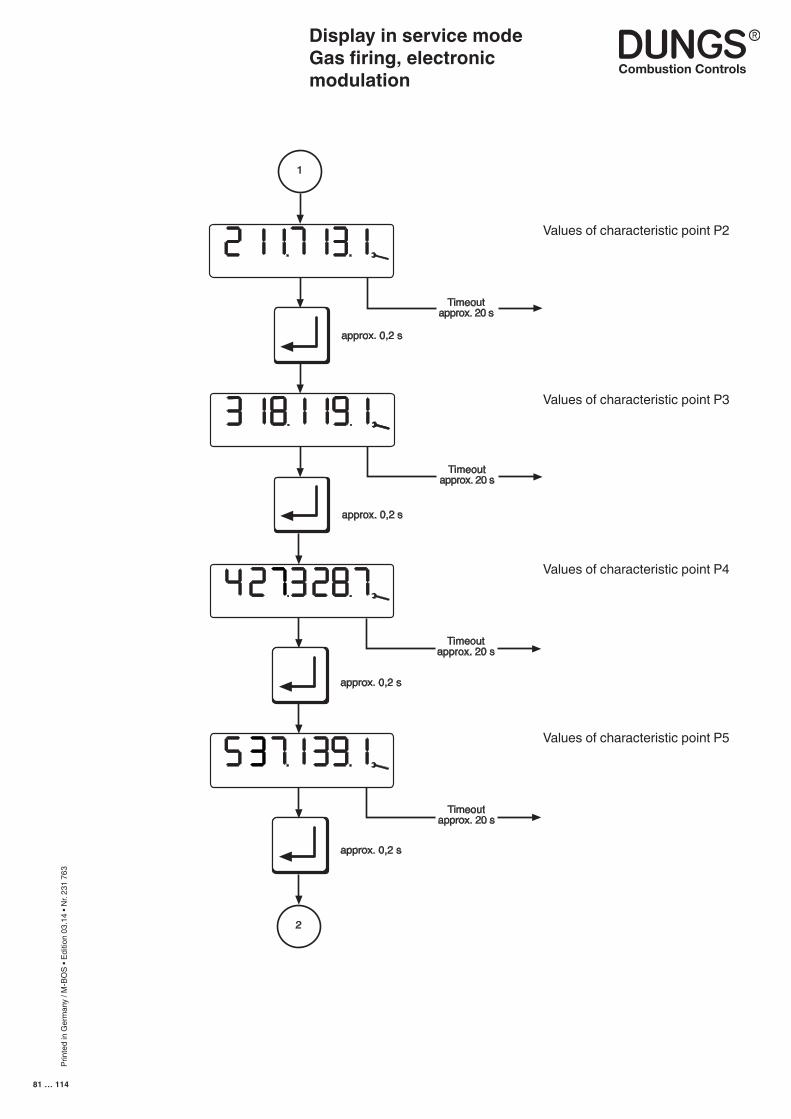
Prin
ted
in G
erm
any
/ M-B
OS
• Edi
tion
03.1
4 • N
r. 23
1 76
3
81 … 114
Display in service modeGas firing, electronicmodulation
Values of characteristic point P2
Values of characteristic point P3
approx. 0,2 s
Timeoutapprox. 20 s
approx. 0,2 s
Timeoutapprox. 20 s
1
Timeoutapprox. 20 s
approx. 0,2 s
Timeoutapprox. 20 s
approx. 0,2 s
2
Values of characteristic point P4
Values of characteristic point P5
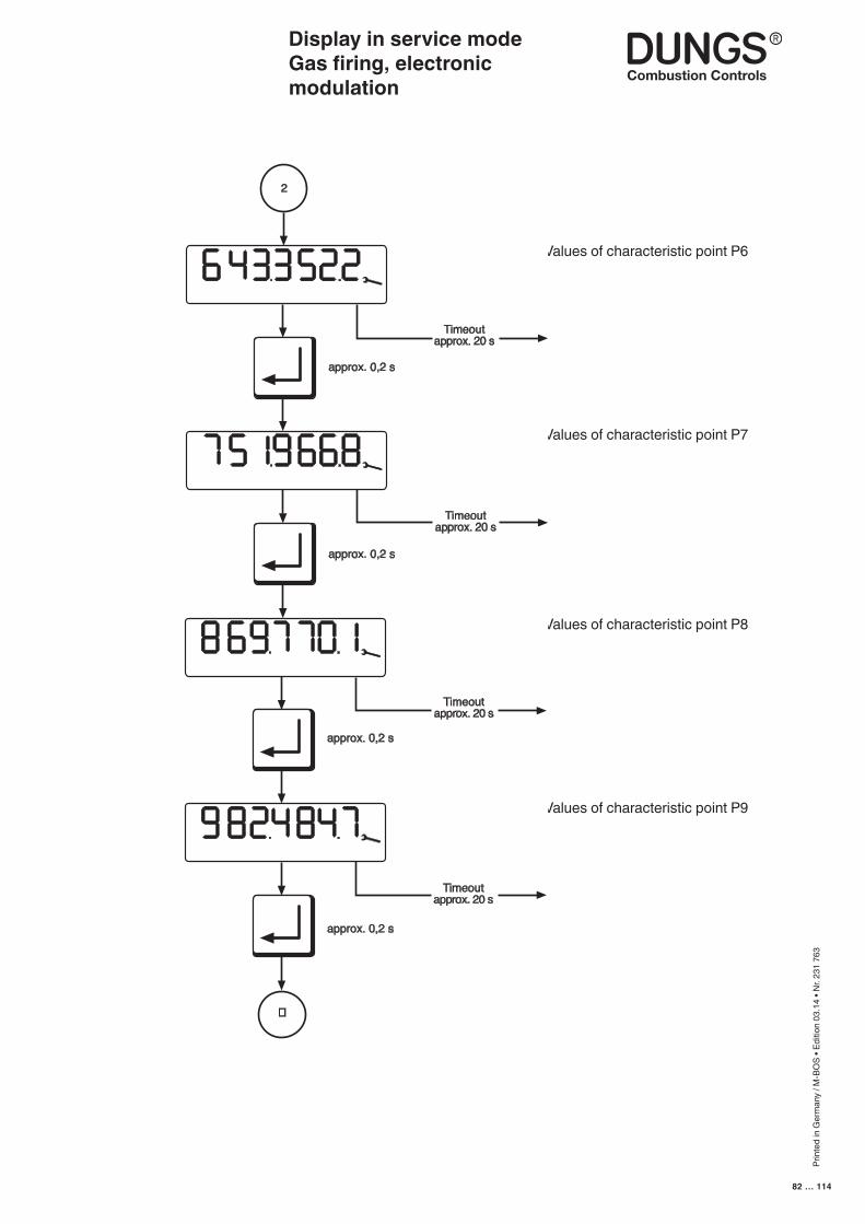
Prin
ted
in G
erm
any
/ M-B
OS
• Edi
tion
03.1
4 • N
r. 23
1 76
3
82 … 114
Values of characteristic point P8
Values of characteristic point P9
Display in service modeGas firing, electronic modulation
Values of characteristic point P6
Values of characteristic point P7
Timeoutapprox. 20 s
approx. 0,2 s
Timeoutapprox. 20 s
approx. 0,2 s
Timeoutapprox. 20 s
approx. 0,2 s
Timeoutapprox. 20 s
approx. 0,2 s
�
2
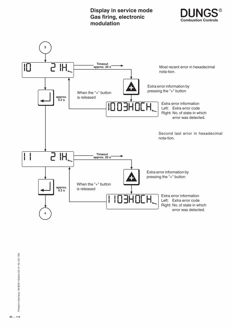
Prin
ted
in G
erm
any
/ M-B
OS
• Edi
tion
03.1
4 • N
r. 23
1 76
3
83 … 114
3
Timeoutapprox. 20 s
approx.0.2 s
approx.0.2 s
+
4
Timeoutapprox. 20 s
+ Extra error information by pressing the "+" button
Extra error informationLeft: Extra error codeRight: No. of state in which
error was detected.
When the "+" buttonis released
Most recent error in hexadecimal nota-tion.
When the "+" buttonis released
Extra error informationLeft: Extra error codeRight: No. of state in which
error was detected.
Extra error information by pressing the "+" button
Second last error in hexadecimal nota-tion.
Display in service modeGas firing, electronic modulation
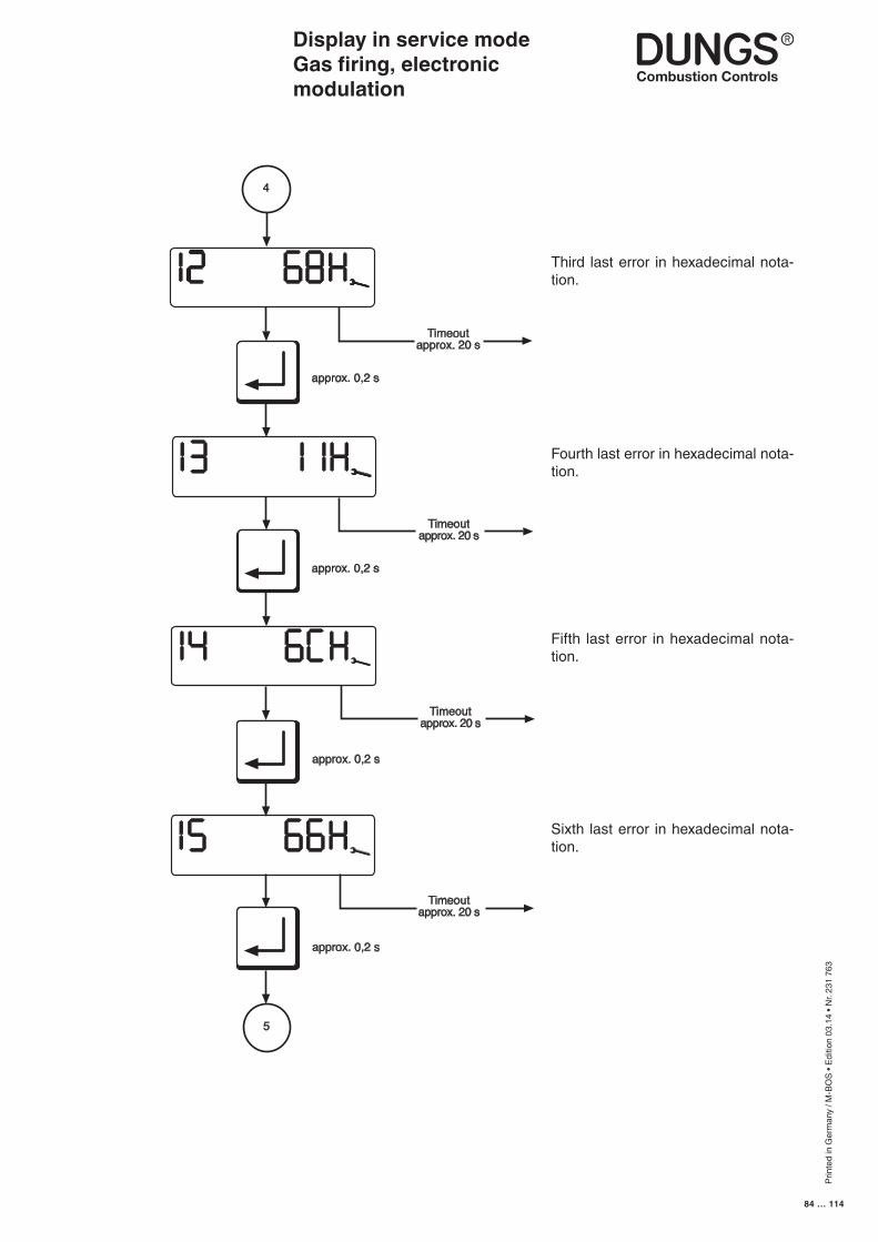
Prin
ted
in G
erm
any
/ M-B
OS
• Edi
tion
03.1
4 • N
r. 23
1 76
3
84 … 114
Display in service modeGas firing, electronic modulation
i
approx. 0,2 s
approx. 0,2 s
Timeoutapprox. 20 s
5
i
4
Timeoutapprox. 20 s
Timeoutapprox. 20 s
Timeoutapprox. 20 s
approx. 0,2 s
approx. 0,2 s
Fifth last error in hexadecimal nota-tion.
Sixth last error in hexadecimal nota-tion.
Third last error in hexadecimal nota-tion.
Fourth last error in hexadecimal nota-tion.
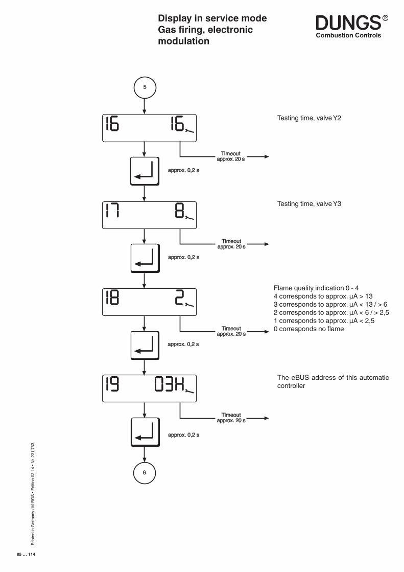
Prin
ted
in G
erm
any
/ M-B
OS
• Edi
tion
03.1
4 • N
r. 23
1 76
3
85 … 114
6
Timeoutapprox. 20 s
Timeoutapprox. 20 s
approx. 0,2 s
approx. 0,2 s
5
approx. 0,2 s
Timeoutapprox. 20 s
Timeoutapprox. 20 s
approx. 0,2 s
Display in service modeGas firing, electronic modulation
Testing time, valve Y2
Flame quality indication 0 - 44 corresponds to approx. µA > 133 corresponds to approx. µA < 13 / > 62 corresponds to approx. µA < 6 / > 2,51 corresponds to approx. µA < 2,5 0 corresponds no flame
The eBUS address of this automatic controller
Testing time, valve Y3
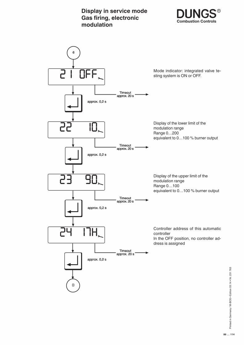
Prin
ted
in G
erm
any
/ M-B
OS
• Edi
tion
03.1
4 • N
r. 23
1 76
3
86 … 114
Display in service modeGas firing, electronic modulation
Timeoutapprox. 20 s
Timeoutapprox. 20 s
approx. 0,2 s
approx. 0,2 s
6
approx. 0,2 s
Timeoutapprox. 20 s
Timeoutapprox. 20 s
approx. 0,2 s
Mode indicator: integrated valve te-sting system is ON or OFF.
Display of the lower limit of the modulation rangeRange 0…200equivalent to 0…100 % burner output
Display of the upper limit of the modulation rangeRange 0…100equivalent to 0…100 % burner output
Controller address of this automatic controllerIn the OFF position, no controller ad-dress is assigned

Prin
ted
in G
erm
any
/ M-B
OS
• Edi
tion
03.1
4 • N
r. 23
1 76
3
87 … 114
Display modulation delay 0-150 = no delay15 = maximum delay
Display starting points - air and gas 0-3
Display in service modeGas firing, electronic modulation
Timeoutapprox. 20 s
7
L/A
G
1
approx. 0,2 s
Back to operatingdisplay
Timeoutapprox. 20 s
approx. 0,2 s
Display controller enable time0..59 s
Prin
ted
in G
erm
any
/ M-B
OS
• Edi
tion
03.1
4 • N
r. 23
1 76
3
88 … 114
Display in service modeGas firing, pneumatic modulation
The service display can be called irrespective of the burner status and provides information on the characteristic stored in the EEPROM.The following data are displayed:
- The characteristic points P0, P1 and P9- The last 6 error messages- The test times of the valve testing system- Flame quality- The e-BUS address- The switch position of the valve testing system- Controller address
This display mode is exited after a 20-second timeout or if the readout is scrolled past the last item.
■ The service-mode display can be accessed only from the operat-ing-mode display.
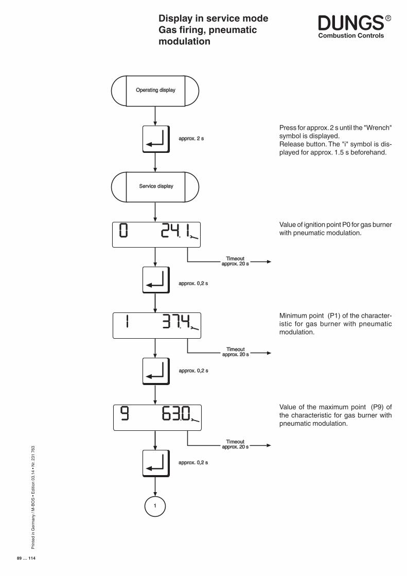
Prin
ted
in G
erm
any
/ M-B
OS
• Edi
tion
03.1
4 • N
r. 23
1 76
3
89 … 114
Display in service modeGas firing, pneumatic modulation
Press for approx. 2 s until the "Wrench" symbol is displayed.Release button. The "i" symbol is dis-played for approx. 1.5 s beforehand.
Value of ignition point P0 for gas burner with pneumatic modulation.
Minimum point (P1) of the character-istic for gas burner with pneumatic modulation.
N
approx. 0,2 s
approx. 0,2 s
Timeoutapprox. 20 s
i
Service display
Operating display
1
approx. 0,2 s
approx. 2 s
Timeoutapprox. 20 s
Timeoutapprox. 20 s
Value of the maximum point (P9) of the characteristic for gas burner with pneumatic modulation.
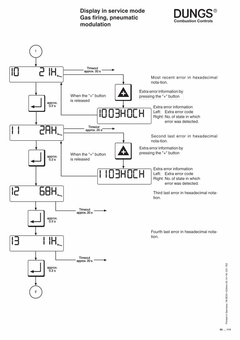
Prin
ted
in G
erm
any
/ M-B
OS
• Edi
tion
03.1
4 • N
r. 23
1 76
3
90 … 114
Display in service modeGas firing, pneumatic modulation
Most recent error in hexadecimal nota-tion.
Second last error in hexadecimal nota-tion.
Third last error in hexadecimal nota-tion.
Fourth last error in hexadecimal nota-tion.
Extra error informationLeft: Extra error codeRight: No. of state in which
error was detected.
When the "+" buttonis released
When the "+" buttonis released
Extra error information by pressing the "+" button
Extra error information by pressing the "+" button
Extra error informationLeft: Extra error codeRight: No. of state in which
error was detected.
approx.0.2 s
1
+
Timeoutapprox. 20 s
Timeoutapprox. 20 s
Timeoutapprox. 20 s
2
approx.0.2 s
approx.0.2 s
approx.0.2 s
Timeoutapprox. 20 s
+
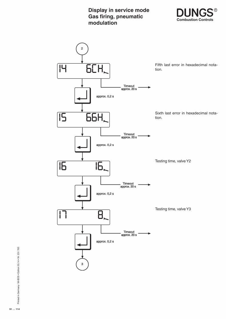
Prin
ted
in G
erm
any
/ M-B
OS
• Edi
tion
03.1
4 • N
r. 23
1 76
3
91 … 114
Display in service modeGas firing, pneumatic modulation
Fifth last error in hexadecimal nota-tion.
Sixth last error in hexadecimal nota-tion.
Testing time, valve Y2
Testing time, valve Y3
approx. 0,2 s
2
approx. 0,2 s
approx. 0,2 s
approx. 0,2 s
3
Timeoutapprox. 20 s
Timeoutapprox. 20 s
Timeoutapprox. 20 s
Timeoutapprox. 20 s
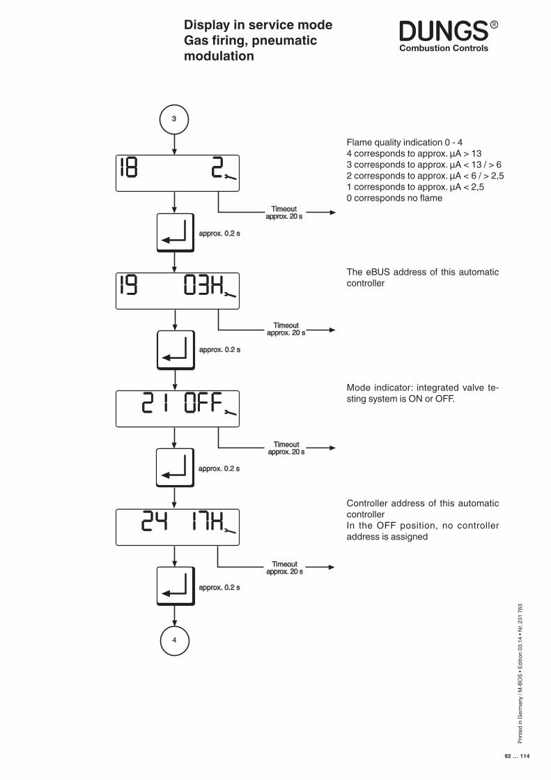
Prin
ted
in G
erm
any
/ M-B
OS
• Edi
tion
03.1
4 • N
r. 23
1 76
3
92 … 114
Display in service modeGas firing, pneumatic modulation
Flame quality indication 0 - 44 corresponds to approx. µA > 133 corresponds to approx. µA < 13 / > 62 corresponds to approx. µA < 6 / > 2,51 corresponds to approx. µA < 2,5 0 corresponds no flame
The eBUS address of this automatic controller
approx. 0.2 s
3
approx. 0.2 s
Timeoutapprox. 20 s
approx. 0.2 s
i
approx. 0.2 s
4
Timeoutapprox. 20 s
Timeoutapprox. 20 s
Timeoutapprox. 20 s
Mode indicator: integrated valve te-sting system is ON or OFF.
Controller address of this automatic controllerIn the OFF position, no controller address is assigned

Prin
ted
in G
erm
any
/ M-B
OS
• Edi
tion
03.1
4 • N
r. 23
1 76
3
93 … 114
Display in service modeGas firing, pneumatic modulation
Timeoutapprox. 20 s
7
L/A
G
1
approx. 0,2 s
Back to operatingdisplay
Timeoutapprox. 20 s
approx. 0,2 s
Display modulation delay 0-150 = no delay15 = maximum delay
Display starting points - air and gas 0-3
Display controller enable time0..59 s
Prin
ted
in G
erm
any
/ M-B
OS
• Edi
tion
03.1
4 • N
r. 23
1 76
3
94 … 114
Display in service modeOil firing, three stage
The service display can be called irrespective of the burner status and provides information on the characteristic stored in the EEPROM.The following data are displayed:
- The characteristic points P0, P1, P3 and P9- The changeover points P2, P4- The last 6 error messages- Flame quality- The e-BUS address- The switch position of the monitor function- Controller address
This display mode is exited after a 20-second timeout or if the readout is scrolled past the last item.
■ The service-mode display can be accessed only from the operat-ing-mode display.
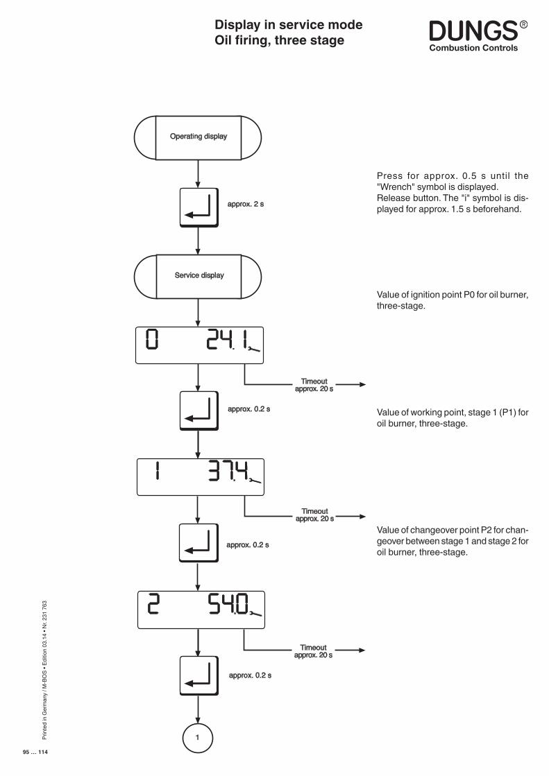
Prin
ted
in G
erm
any
/ M-B
OS
• Edi
tion
03.1
4 • N
r. 23
1 76
3
95 … 114
Display in service modeOil firing, three stage
Value of ignition point P0 for oil burner, three-stage.
Value of working point, stage 1 (P1) for oil burner, three-stage.
Value of changeover point P2 for chan-geover between stage 1 and stage 2 for oil burner, three-stage.
Press for approx. 0.5 s until the "Wrench" symbol is displayed.Release button. The "i" symbol is dis-played for approx. 1.5 s beforehand.
N
approx. 0.2 s
approx. 0.2 s
i
Service display
Operating display
1
approx. 0.2 s
Timeoutapprox. 20 s
approx. 2 s
Timeoutapprox. 20 s
Timeoutapprox. 20 s
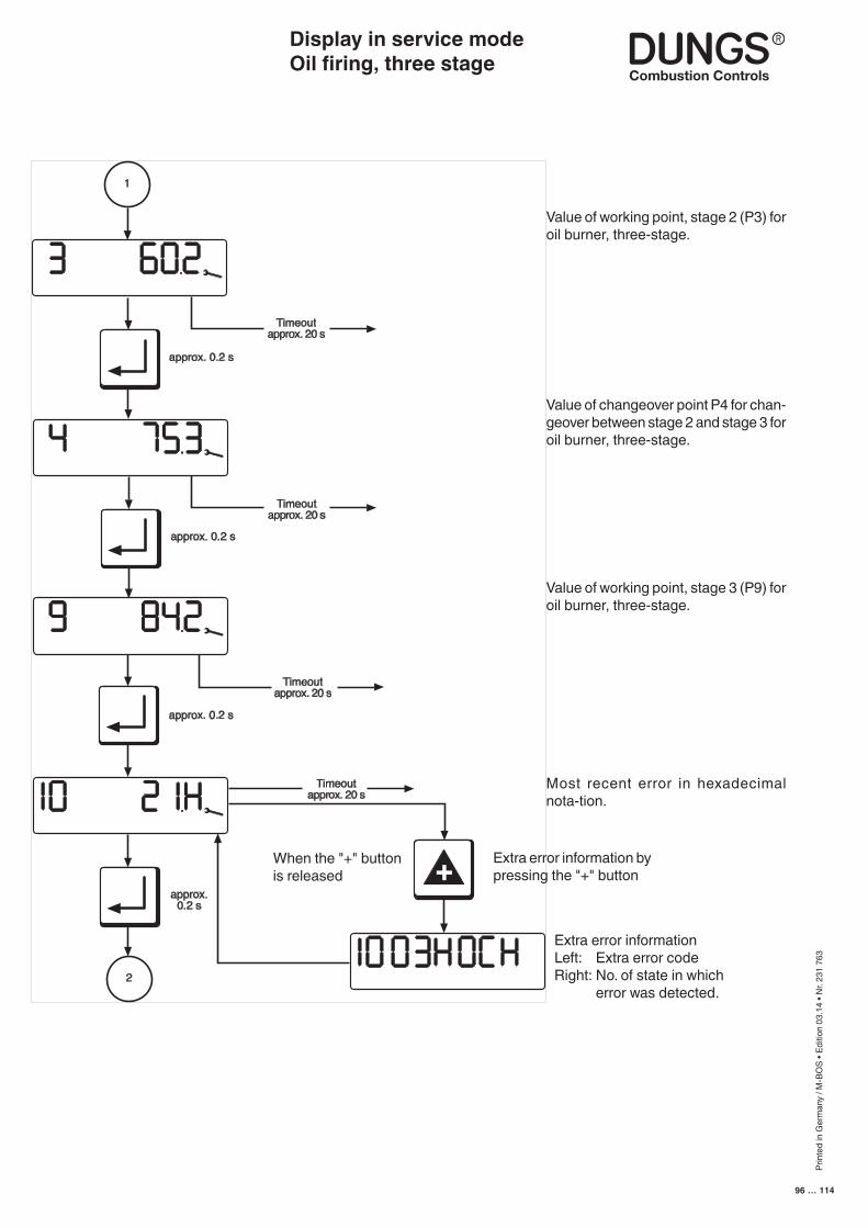
Prin
ted
in G
erm
any
/ M-B
OS
• Edi
tion
03.1
4 • N
r. 23
1 76
3
96 … 114
Display in service modeOil firing, three stage
Value of working point, stage 2 (P3) for oil burner, three-stage.
Value of changeover point P4 for chan-geover between stage 2 and stage 3 for oil burner, three-stage.
Timeoutapprox. 20 s
1
2
+
approx. 0.2 s
approx. 0.2 s
approx. 0.2 s
approx.0.2 s
Timeoutapprox. 20 s
Timeoutapprox. 20 s
Timeoutapprox. 20 s
Value of working point, stage 3 (P9) for oil burner, three-stage.
Most recent error in hexadecimal nota-tion.
Extra error informationLeft: Extra error codeRight: No. of state in which
error was detected.
When the "+" buttonis released
Extra error information by pressing the "+" button
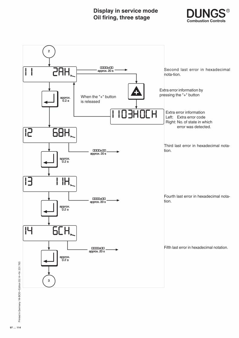
Prin
ted
in G
erm
any
/ M-B
OS
• Edi
tion
03.1
4 • N
r. 23
1 76
3
97 … 114
Display in service modeOil firing, three stage
Second last error in hexadecimal nota-tion.
Third last error in hexadecimal nota-tion.
Fourth last error in hexadecimal nota-tion.
Fifth last error in hexadecimal notation.
Extra error informationLeft: Extra error codeRight: No. of state in which
error was detected.
When the "+" buttonis released
Extra error information by pressing the "+" button
approx. 0.2 s
+
2
3
approx. 0.2 s
����o��approx. 20 s
����o��approx. 20 s
����o��approx. 20 s
����o��approx. 20 s
approx. 0.2 s
approx. 0.2 s
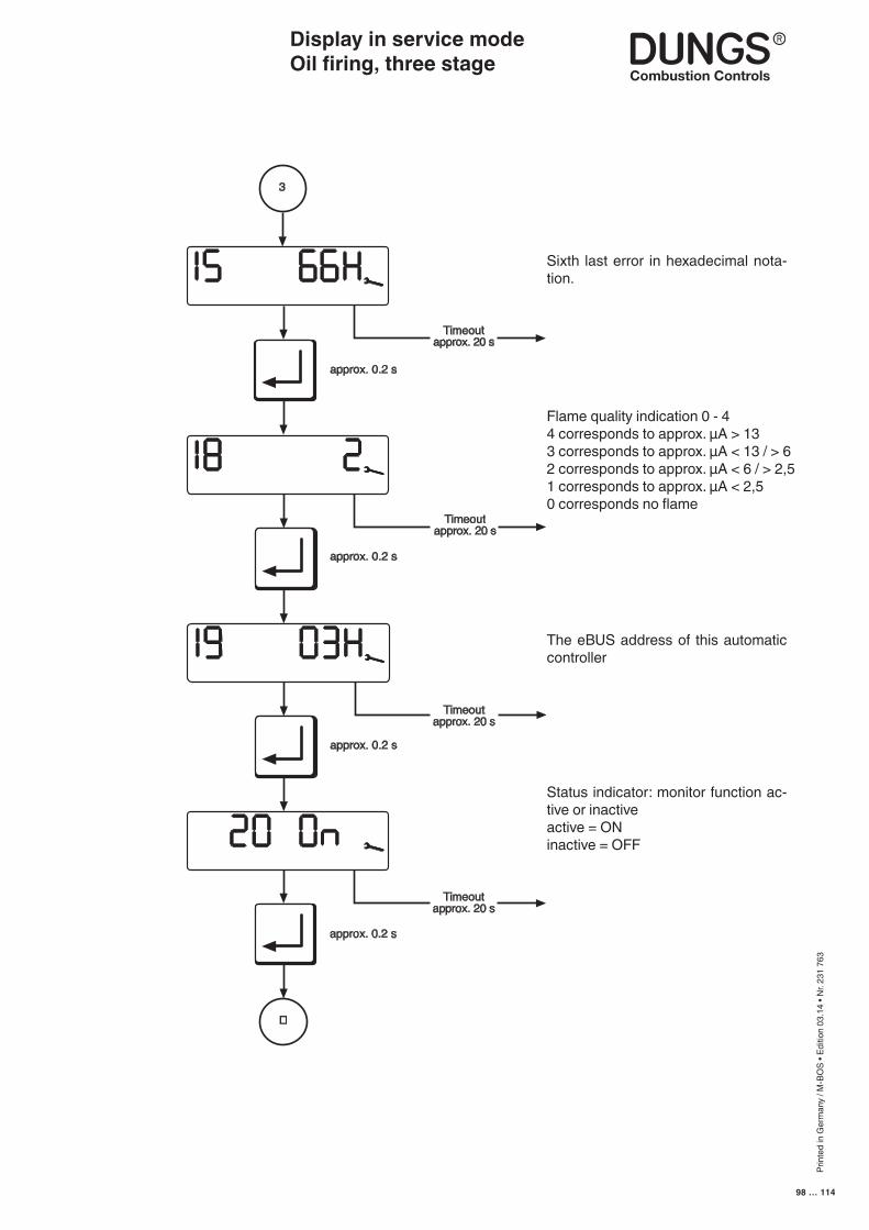
Prin
ted
in G
erm
any
/ M-B
OS
• Edi
tion
03.1
4 • N
r. 23
1 76
3
98 … 114
Display in service mode Oil firing, three stage
Sixth last error in hexadecimal nota-tion.
The eBUS address of this automatic controller
approx. 0.2 s
Timeoutapprox. 20 s
Timeoutapprox. 20 s
3
�
approx. 0.2 s
approx. 0.2 s
approx. 0.2 s
Timeoutapprox. 20 s
Timeoutapprox. 20 s
Flame quality indication 0 - 44 corresponds to approx. µA > 133 corresponds to approx. µA < 13 / > 62 corresponds to approx. µA < 6 / > 2,51 corresponds to approx. µA < 2,5 0 corresponds no flame
Status indicator: monitor function ac-tive or inactiveactive = ONinactive = OFF
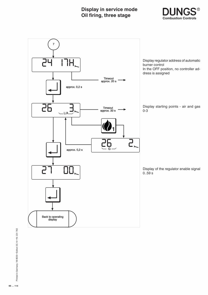
Prin
ted
in G
erm
any
/ M-B
OS
• Edi
tion
03.1
4 • N
r. 23
1 76
3
99 … 114
Display regulator address of automatic burner controlIn the OFF position, no controller ad-dress is assigned
Display in service mode Oil firing, three stage
Timeoutapprox. 20 s
approx. 0,2 s
7
L/A
G
1
Back to operatingdisplay
Timeoutapprox. 20 s
approx. 0,2 s
Display starting points - air and gas 0-3
Display of the regulator enable signal 0..59 s
Prin
ted
in G
erm
any
/ M-B
OS
• Edi
tion
03.1
4 • N
r. 23
1 76
3
100 … 114
Parameterisation mode can be accessed only from the operating-mode display when the controller is on standby ("OFF"). Parameterisation mode is used to view important operating parameters and adjust the settings by means of the buttons on the touch-sensitive display.
Paramterisation mode defines access priority in such a way that all service-level parameters can be configured with MPA Vision.
This display mode is exited after a 20-second timeout or if the readout is scrolled past the last display image.
Display in parameterisation modeGas firing, electronic modulationGas firing, pneumatic modulationOil firing, three stage
■ The parameterisation-mode dis-play can be accessed only from the operating-mode display in standby status.
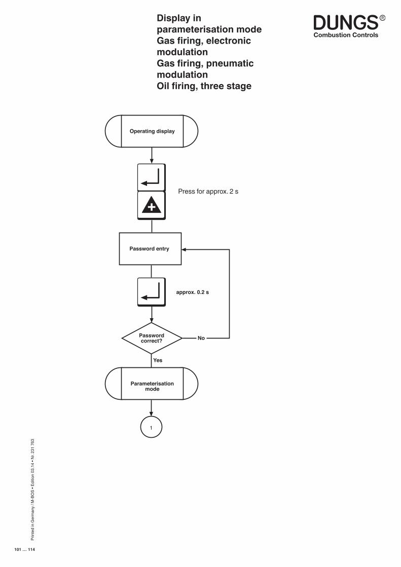
Prin
ted
in G
erm
any
/ M-B
OS
• Edi
tion
03.1
4 • N
r. 23
1 76
3
101 … 114
Display in parameterisation modeGas firing, electronic modulationGas firing, pneumatic modulationOil firing, three stage
+
1
Passwordcorrect?
Password entry
No
Yes
Operating display
Parameterisationmode
approx. 0.2 s
Press for approx. 2 s
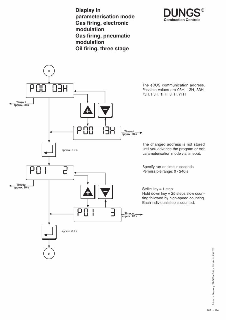
Prin
ted
in G
erm
any
/ M-B
OS
• Edi
tion
03.1
4 • N
r. 23
1 76
3
102 … 114
The changed address is not stored until you advance the program or exit parameterisation mode via timeout.
Specify run-on time in secondsPermissible range: 0 - 240 s
The eBUS communication address. Possible values are 03H, 13H, 33H, 73H, F3H, 1FH, 3FH, 7FH
Display in parameterisation modeGas firing, electronic modulationGas firing, pneumatic modulationOil firing, three stage
Timeoutapprox. 20 s
+
approx. 0.2 s
�
–
+
–
2
Timeoutapprox. 20 s
Timeoutapprox. 20 s
Timeoutapprox. 20 s
approx. 0.2 s
Strike key = 1 stepHold down key = 25 steps slow coun-ting followed by high-speed counting. Each individual step is counted.
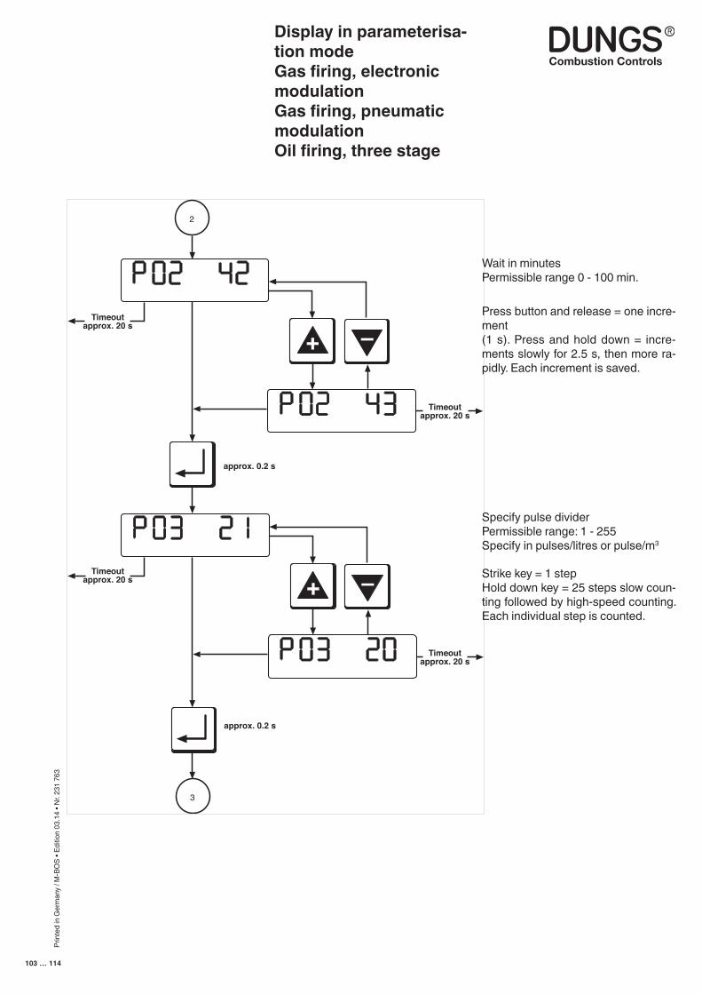
Prin
ted
in G
erm
any
/ M-B
OS
• Edi
tion
03.1
4 • N
r. 23
1 76
3
103 … 114
Wait in minutesPermissible range 0 - 100 min.
Press button and release = one incre-ment (1 s). Press and hold down = incre-ments slowly for 2.5 s, then more ra-pidly. Each increment is saved.
Display in parameterisa-tion modeGas firing, electronic modulationGas firing, pneumatic modulationOil firing, three stage
Specify pulse dividerPermissible range: 1 - 255Specify in pulses/litres or pulse/m3
Strike key = 1 stepHold down key = 25 steps slow coun-ting followed by high-speed counting. Each individual step is counted.
Timeoutapprox. 20 s
Timeoutapprox. 20 s
approx. 0.2 s
2
+
–
Timeoutapprox. 20 s
Timeoutapprox. 20 s
+
–
approx. 0.2 s
3
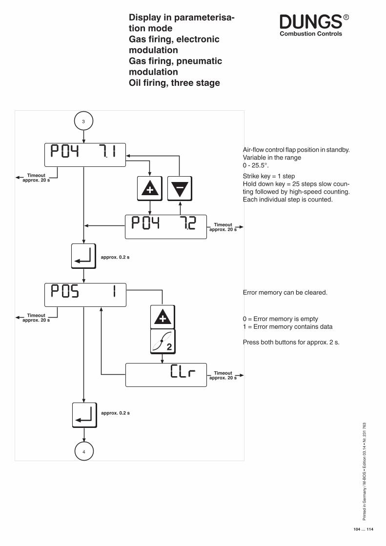
Prin
ted
in G
erm
any
/ M-B
OS
• Edi
tion
03.1
4 • N
r. 23
1 76
3
104 … 114
Timeoutapprox. 20 s
Timeoutapprox. 20 s
approx. 0.2 s
3
+
–
Timeoutapprox. 20 s +
2
Timeoutapprox. 20 s
approx. 0.2 s
4
Display in parameterisa-tion modeGas firing, electronic modulationGas firing, pneumatic modulationOil firing, three stage
Air-flow control flap position in standby. Variable in the range 0 - 25.5°.Strike key = 1 stepHold down key = 25 steps slow coun-ting followed by high-speed counting. Each individual step is counted.
Error memory can be cleared.
0 = Error memory is empty1 = Error memory contains data
Press both buttons for approx. 2 s.
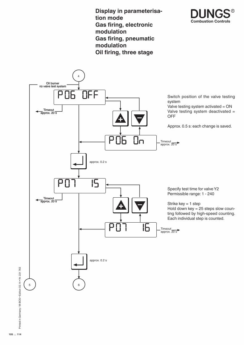
Prin
ted
in G
erm
any
/ M-B
OS
• Edi
tion
03.1
4 • N
r. 23
1 76
3
105 … 114
Timeoutapprox. 20 s
Timeoutapprox. 20 s
approx. 0.2 s
4
+
–
Timeoutapprox. 20 s
approx. 0.2 s
65
Oil burnerno valve test system
+
–
Timeoutapprox. 20 s
Switch position of the valve testing system Valve testing system activated = ONValve testing system deactivated = OFF
Approx. 0.5 s: each change is saved.
Specify test time for valve Y2Permissible range: 1 - 240
Strike key = 1 stepHold down key = 25 steps slow coun-ting followed by high-speed counting. Each individual step is counted.
Display in parameterisa-tion modeGas firing, electronic modulationGas firing, pneumatic modulationOil firing, three stage
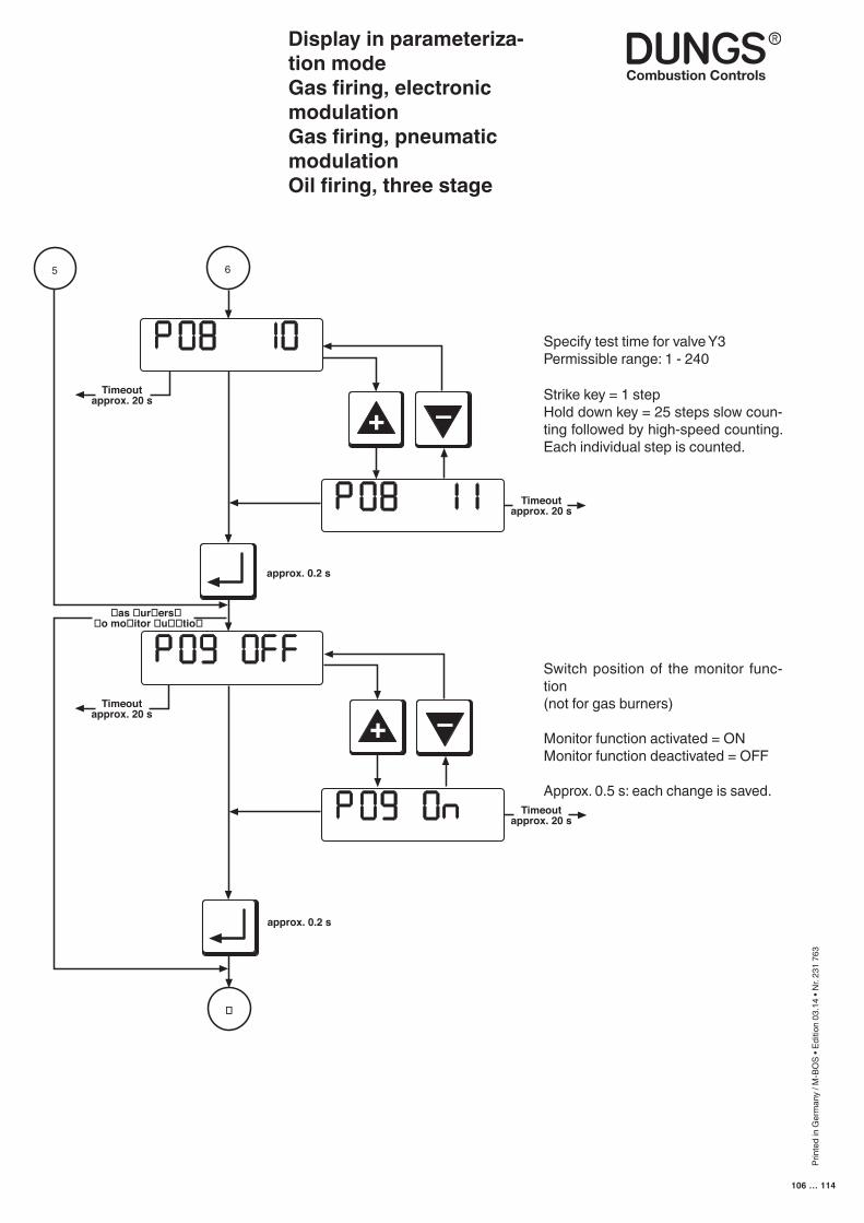
Prin
ted
in G
erm
any
/ M-B
OS
• Edi
tion
03.1
4 • N
r. 23
1 76
3
106 … 114
Timeoutapprox. 20 s
Timeoutapprox. 20 s
approx. 0.2 s
6
+
–
Timeoutapprox. 20 s
approx. 0.2 s
as ur ers o mo itor u tio
+
–
Timeoutapprox. 20 s
5
�
Specify test time for valve Y3Permissible range: 1 - 240
Strike key = 1 stepHold down key = 25 steps slow coun-ting followed by high-speed counting. Each individual step is counted.
Switch position of the monitor func-tion(not for gas burners)
Monitor function activated = ONMonitor function deactivated = OFF
Approx. 0.5 s: each change is saved.
Display in parameteriza-tion modeGas firing, electronic modulationGas firing, pneumatic modulationOil firing, three stage
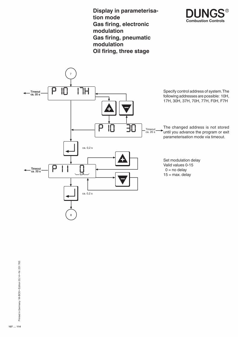
Prin
ted
in G
erm
any
/ M-B
OS
• Edi
tion
03.1
4 • N
r. 23
1 76
3
107 … 114
Display in parameterisa-tion modeGas firing, electronic modulationGas firing, pneumatic modulationOil firing, three stage
Specify control address of system. The following addresses are possible: 10H, 17H, 30H, 37H, 70H, 77H, F0H, F7H
The changed address is not stored until you advance the program or exit parameterisation mode via timeout.
–
+
7
ca. 0,2 s
L/A
Timeoutca. 20 s
8
Timeoutca. 20 s
Timeoutca. 20 s
–+
ca. 0,2 s
Set modulation delayValid values 0-15 0 = no delay15 = max. delay
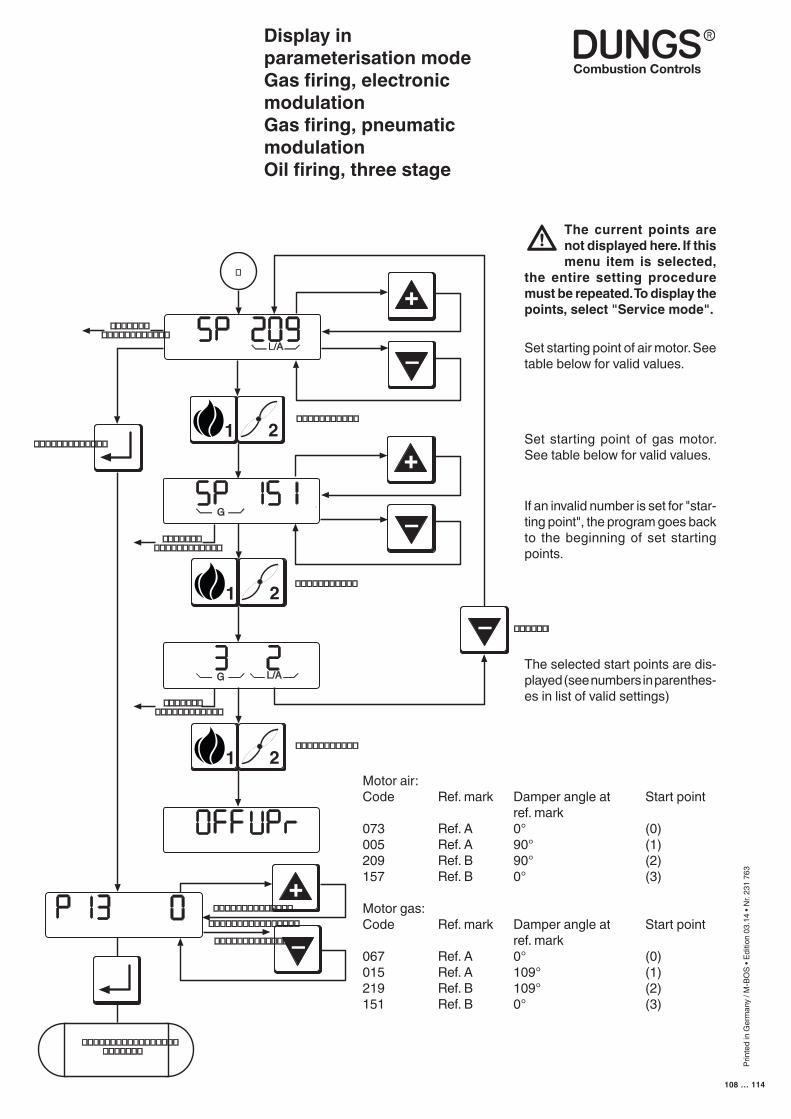
Prin
ted
in G
erm
any
/ M-B
OS
• Edi
tion
03.1
4 • N
r. 23
1 76
3
108 … 114
Display in parameterisation modeGas firing, electronic modulationGas firing, pneumatic modulationOil firing, three stage
–
G L/A
21
G
21–
+
21
L/A
–
+
�������������������
�����������
�����������
�
�������
�������������
�����������
�������������������
�������������������
–
+
������������������������
������������������������������
�������������
Set starting point of air motor. See table below for valid values.
Motor air:Code Ref. mark Damper angle at Start point ref. mark073 Ref. A 0° (0)005 Ref. A 90° (1)209 Ref. B 90° (2)157 Ref. B 0° (3)
Motor gas:Code Ref. mark Damper angle at Start point ref. mark067 Ref. A 0° (0)015 Ref. A 109° (1)219 Ref. B 109° (2)151 Ref. B 0° (3)
Set starting point of gas motor. See table below for valid values.
If an invalid number is set for "star-ting point", the program goes back to the beginning of set starting points.
The selected start points are dis-played (see numbers in parenthes-es in list of valid settings)
The current points are not displayed here. If this menu item is selected,
the entire setting procedure must be repeated. To display the points, select "Service mode".
Prin
ted
in G
erm
any
/ M-B
OS
• Edi
tion
03.1
4 • N
r. 23
1 76
3
109 … 114
Error indicationGas firing, electronic modulationGas firing, pneumatic modulationOil firing, three stage
Error mode overwrites all other display modes.Error mode is not active unless a error is detected.
The following appears on the display:
• An "F" on the left• The "Flame with strike-through" symbol • The error code in hexadecimal notation; occupies the three places on the
right. • The error code flashes
The error codes are listed complete with their individual meanings in the Error Codes list below.
Press the "+" button to call up an extra error code which provides more detailed information on the error, along with details of the program state in which the error occurred. The extra error code does not flash on the display.
You must press the "Acknowledgment" or "Reset" button to reset.
■ Error mode
■ Error indication
■ Error code
■ Extra error code
■ Reset
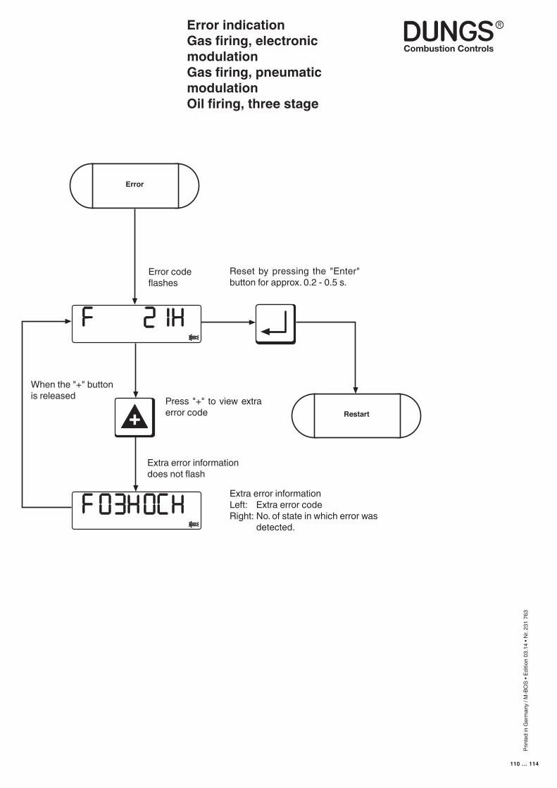
Prin
ted
in G
erm
any
/ M-B
OS
• Edi
tion
03.1
4 • N
r. 23
1 76
3
110 … 114
+
Error
Restart
Error indicationGas firing, electronic modulationGas firing, pneumatic modulationOil firing, three stage
Error codeflashes
Reset by pressing the "Enter" button for approx. 0.2 - 0.5 s.
When the "+" button is released Press "+" to view extra
error code
Extra error informationLeft: Extra error codeRight: No. of state in which error was
detected.
Extra error informationdoes not flash
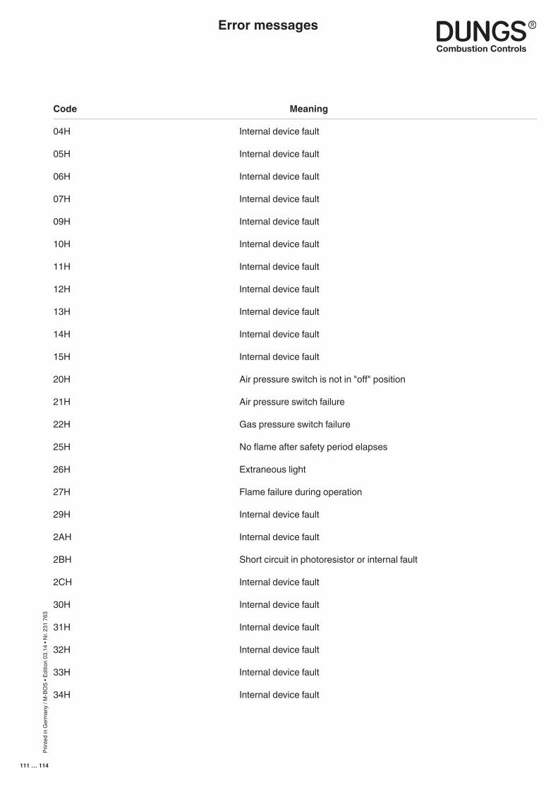
Prin
ted
in G
erm
any
/ M-B
OS
• Edi
tion
03.1
4 • N
r. 23
1 76
3
111 … 114
Code Meaning
04H Internal device fault
05H Internal device fault
06H Internal device fault
07H Internal device fault
09H Internal device fault
10H Internal device fault
11H Internal device fault
12H Internal device fault
13H Internal device fault
14H Internal device fault
15H Internal device fault
20H Air pressure switch is not in "off" position
21H Air pressure switch failure
22H Gas pressure switch failure
25H No flame after safety period elapses
26H Extraneous light
27H Flame failure during operation
29H Internal device fault
2AH Internal device fault
2BH Short circuit in photoresistor or internal fault
2CH Internal device fault
30H Internal device fault
31H Internal device fault
32H Internal device fault
33H Internal device fault
34H Internal device fault
Error messages
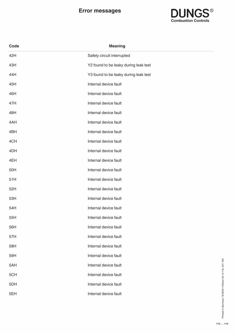
Prin
ted
in G
erm
any
/ M-B
OS
• Edi
tion
03.1
4 • N
r. 23
1 76
3
112 … 114
Code Meaning
42H Safety circuit interrupted
43H Y2 found to be leaky during leak test
44H Y3 found to be leaky during leak test
45H Internal device fault
46H Internal device fault
47H Internal device fault
48H Internal device fault
4AH Internal device fault
4BH Internal device fault
4CH Internal device fault
4DH Internal device fault
4EH Internal device fault
50H Internal device fault
51H Internal device fault
52H Internal device fault
53H Internal device fault
54H Internal device fault
55H Internal device fault
56H Internal device fault
57H Internal device fault
58H Internal device fault
59H Internal device fault 5AH Internal device fault
5CH Internal device fault
5DH Internal device fault
5EH Internal device fault
Error messages
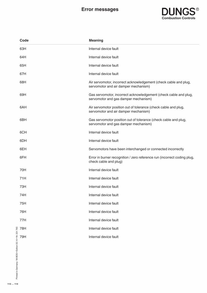
Prin
ted
in G
erm
any
/ M-B
OS
• Edi
tion
03.1
4 • N
r. 23
1 76
3
113 … 114
Code Meaning
63H Internal device fault
64H Internal device fault
65H Internal device fault
67H Internal device fault
68H Air servomotor, incorrect acknowledgement (check cable and plug, servomotor and air damper mechanism)
69H Gas servomotor, incorrect acknowledgement (check cable and plug, servomotor and gas damper mechanism)
6AH Air servomotor position out of tolerance (check cable and plug, servomotor and air damper mechanism)
6BH Gas servomotor position out of tolerance (check cable and plug, servomotor and gas damper mechanism)
6CH Internal device fault
6DH Internal device fault
6EH Servomotors have been interchanged or connected incorrectly
6FH Error in burner recognition / zero reference run (incorrect coding plug, check cable and plug)
70H Internal device fault
71H Internal device fault
73H Internal device fault
74H Internal device fault
75H Internal device fault
76H Internal device fault
77H Internal device fault
78H Internal device fault
79H Internal device fault
Error messages

Prin
ted
in G
erm
any
/ M-B
OS
• Edi
tion
03.1
4 • N
r. 23
1 76
3
114 … 114