OPERATING AND MAINTENANCE INSTRUCTION - … · OPERATING AND MAINTENANCE INSTRUCTION PAINT SPRAYING...
36
PAINT SPRAYING EQUIPMENT OPERATING AND MAINTENANCE INSTRUCTION ENGLISH OPERATING AND MAINTENANCE INSTRUCTION II 2 G c IIB T4 C E R T I F I C A T A A T E X Ed. 006 11 - 12
Transcript of OPERATING AND MAINTENANCE INSTRUCTION - … · OPERATING AND MAINTENANCE INSTRUCTION PAINT SPRAYING...
PAINT SPRAYING EQUIPMENT
OPE
RATI
NG A
ND
MAI
NTEN
ANCE
INST
RUCT
ION
ENGLISHOPE
RATI
NG A
ND
MAI
NTEN
ANCE
INST
RUCT
ION
II 2 G c IIB T4
C e r t i f i C a t a a t e x
Ed.
006
11 -
12

Due to a constant product improvement programme, the factory reserves the right to modify technical details mentioned in this manual without prior notice.
This manual is to be considered as an English language translation of the original manual in Italian. The manufacturer shall bear no responsibility for any damages or inconveniences that may arise due to the incorrect translation of the instructions contained within the original manual in Italian.
1
GHIBLI 30:1/40:1English
Q
ComplETE pumpInG pump GhIBlI SplIT
VERSIon 30:1 / 40:1 ........................................p.20
ComplETE pumpInG pump GhIBlI SplIT
VERSIon STaInlESS STEEl 30:1 / 40:1 .........p.22
aIR REGulaTIon GRoup aIRlESS ...............p.24
aIR REGulaTIon GRoup mISTlESS VERS. ...p.25
paInT SuCTIon SySTEm ................................p.26
ComplETE TRollEy .......................................p.27
aCCESSoRIES ..................................................p.28
ATEX CERTIFICATION
DESCRIpTIon ...................................................p.31
TEChnICal ChaRaCTERISTICS ....................p.31
maRKInGS ........................................................p.32
SaFETy InSTRuCTIonS FoR
InSTallaTIon In haZaRDouS aREaS .........p.32
EXamplE oF InSTallaTIon ...........................p.33
CERTIFICaTE oF ConFoRmITy .....................p.33
n
o
p
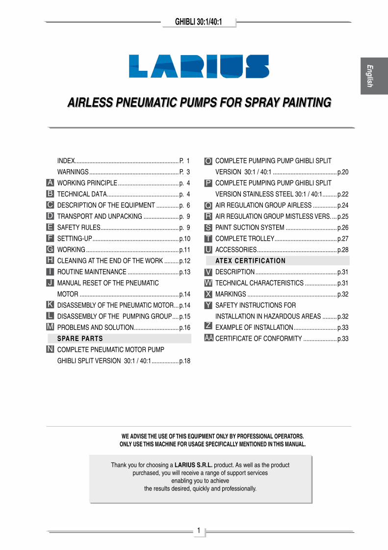
InDEX .................................................................p. 1
WaRnInGS ........................................................p. 3
WoRKInG pRInCIplE ......................................p. 4
TEChnICal DaTa .............................................p. 4
DESCRIpTIon oF ThE EQuIpmEnT ..............p. 6
TRanSpoRT anD unpaCKInG ......................p. 9
SaFETy RulES .................................................p. 9
SETTInG-up ......................................................p.10
WoRKInG ..........................................................p.11
ClEanInG aT ThE EnD oF ThE WoRK .........p.12
RouTInE maInTEnanCE ................................p.13
manual RESET oF ThE pnEumaTIC
moToR ..............................................................p.14
DISaSSEmBly oF ThE pnEumaTIC moToR ...p.14
DISaSSEmBly oF ThE pumpInG GRoup ....p.15
pRoBlEmS anD SoluTIon ............................p.16
SPARE PARTS
ComplETE pnEumaTIC moToR pump
GhIBlI SplIT VERSIon 30:1 / 40:1 .................p.18
aBCDEFGh
J
Klm
I
R
STu
VW
Xy
Z
aa
WE ADVISE THE USE OF THIS EQUIPMENT ONLY BY PROFESSIONAL OPERATORS.ONLY USE THIS MACHINE FOR USAGE SPECIFICALLY MENTIONED IN THIS MANUAL.
Thank you for choosing a LARIUS S.R.L. product. as well as the productpurchased, you will receive a range of support services
enabling you to achievethe results desired, quickly and professionally.
AIRLESS PNEUMATIC PUMPS FOR SPRAY PAINTINGAIRLESS PNEUMATIC PUMPS FOR SPRAY PAINTING

White page
intentionally
3
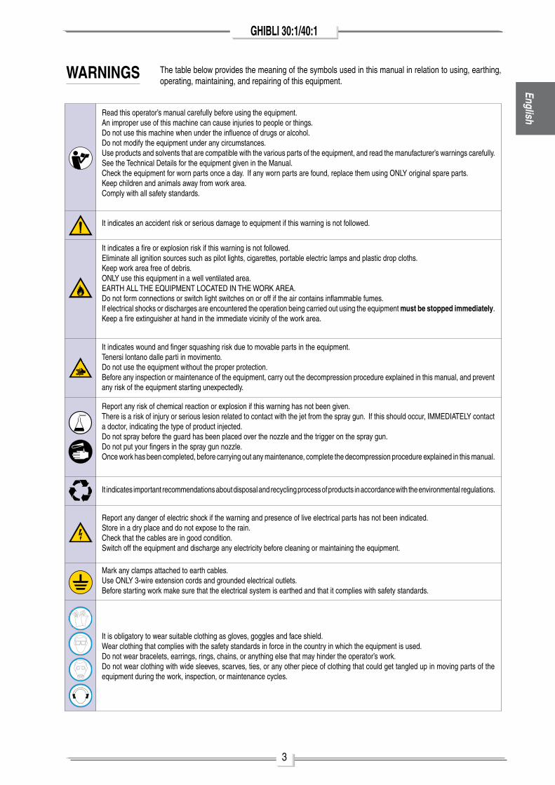
GHIBLI 30:1/40:1EnglishRead this operator’s manual carefully before using the equipment.
an improper use of this machine can cause injuries to people or things.Do not use this machine when under the influence of drugs or alcohol.Do not modify the equipment under any circumstances.use products and solvents that are compatible with the various parts of the equipment, and read the manufacturer’s warnings carefully.See the Technical Details for the equipment given in the manual.Check the equipment for worn parts once a day. If any worn parts are found, replace them using only original spare parts.Keep children and animals away from work area.Comply with all safety standards.
It indicates an accident risk or serious damage to equipment if this warning is not followed.
It indicates important recommendations about disposal and recycling process of products in accordance with the environmental regulations.
WARNINGS The table below provides the meaning of the symbols used in this manual in relation to using, earthing, operating, maintaining, and repairing of this equipment.
It indicates a fire or explosion risk if this warning is not followed.Eliminate all ignition sources such as pilot lights, cigarettes, portable electric lamps and plastic drop cloths.Keep work area free of debris.only use this equipment in a well ventilated area.EaRTh all ThE EQuIpmEnT loCaTED In ThE WoRK aREa.Do not form connections or switch light switches on or off if the air contains inflammable fumes.If electrical shocks or discharges are encountered the operation being carried out using the equipment must be stopped immediately.Keep a fire extinguisher at hand in the immediate vicinity of the work area.
It indicates wound and finger squashing risk due to movable parts in the equipment.Tenersi lontano dalle parti in movimento.Do not use the equipment without the proper protection.Before any inspection or maintenance of the equipment, carry out the decompression procedure explained in this manual, and prevent any risk of the equipment starting unexpectedly.
Report any risk of chemical reaction or explosion if this warning has not been given.There is a risk of injury or serious lesion related to contact with the jet from the spray gun. If this should occur, ImmEDIaTEly contact a doctor, indicating the type of product injected.Do not spray before the guard has been placed over the nozzle and the trigger on the spray gun.Do not put your fingers in the spray gun nozzle.once work has been completed, before carrying out any maintenance, complete the decompression procedure explained in this manual.
Report any danger of electric shock if the warning and presence of live electrical parts has not been indicated.Store in a dry place and do not expose to the rain.Check that the cables are in good condition.Switch off the equipment and discharge any electricity before cleaning or maintaining the equipment.
mark any clamps attached to earth cables.use only 3-wire extension cords and grounded electrical outlets.Before starting work make sure that the electrical system is earthed and that it complies with safety standards.
It is obligatory to wear suitable clothing as gloves, goggles and face shield.Wear clothing that complies with the safety standards in force in the country in which the equipment is used.Do not wear bracelets, earrings, rings, chains, or anything else that may hinder the operator’s work.Do not wear clothing with wide sleeves, scarves, ties, or any other piece of clothing that could get tangled up in moving parts of the equipment during the work, inspection, or maintenance cycles.
4
GHIBLI 30:1/40:1
A
B
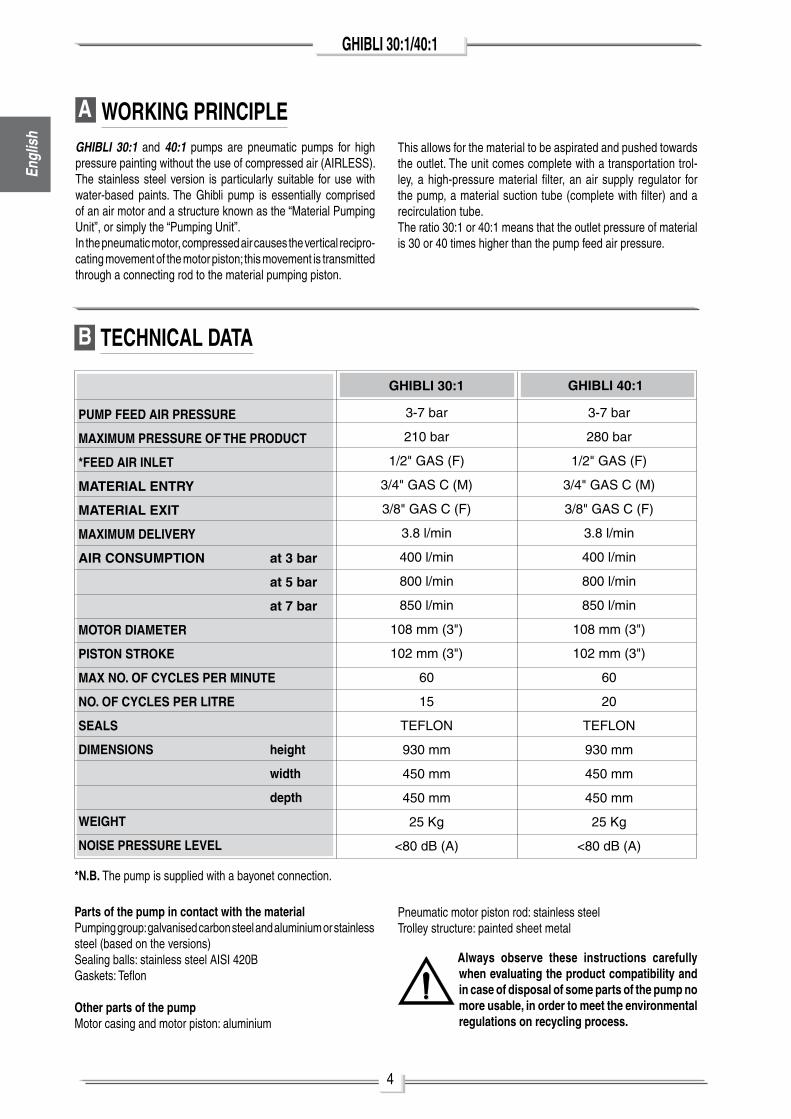
WORKING PRINCIPLEGHIBLI 30:1 and 40:1 pumps are pneumatic pumps for high pressure painting without the use of compressed air (aIRlESS). The stainless steel version is particularly suitable for use with water-based paints. The Ghibli pump is essentially comprised of an air motor and a structure known as the “material pumping unit”, or simply the “pumping unit”. In the pneumatic motor, compressed air causes the vertical recipro-cating movement of the motor piston; this movement is transmitted through a connecting rod to the material pumping piston.
This allows for the material to be aspirated and pushed towards the outlet. The unit comes complete with a transportation trol-ley, a high-pressure material filter, an air supply regulator for the pump, a material suction tube (complete with filter) and a recirculation tube. The ratio 30:1 or 40:1 means that the outlet pressure of material is 30 or 40 times higher than the pump feed air pressure.
TECHNICAL DATA
GHIBLI 30:1
3-7 bar
210 bar
1/2" GaS (F)
3/4" GaS C (m)
3/8" GaS C (F)
3.8 l/min
400 l/min
800 l/min
850 l/min
108 mm (3")
102 mm (3")
60
15
TEFlon
930 mm
450 mm
450 mm
25 Kg
<80 dB (a)
PUMP FEED AIR PRESSURE
MAXIMUM PRESSURE OF THE PRODUCT
*FEED AIR INLET
MATERIAL ENTRY
MATERIAL EXIT
MAXIMUM DELIVERY
AIR CONSUMPTION at 3 bar
at 5 bar
at 7 bar
MOTOR DIAMETER
PISTON STROKE
MAX NO. OF CYCLES PER MINUTE
NO. OF CYCLES PER LITRE
SEALS
DIMENSIONS height
width
depth
WEIGHT
NOISE PRESSURE LEVEL
Parts of the pump in contact with the material pumping group: galvanised carbon steel and aluminium or stainless steel (based on the versions)Sealing balls: stainless steel aISI 420BGaskets: Teflon
Other parts of the pumpmotor casing and motor piston: aluminium
Always observe these instructions carefully when evaluating the product compatibility and in case of disposal of some parts of the pump no more usable, in order to meet the environmental regulations on recycling process.
*N.B. The pump is supplied with a bayonet connection.
GHIBLI 40:1
pneumatic motor piston rod: stainless steelTrolley structure: painted sheet metal
3-7 bar
280 bar
1/2" GaS (F)
3/4" GaS C (m)
3/8" GaS C (F)
3.8 l/min
400 l/min
800 l/min
850 l/min
108 mm (3")
102 mm (3")
60
20
TEFlon
930 mm
450 mm
450 mm
25 Kg
<80 dB (a)
Engl
ish
5
GHIBLI 30:1/40:1English
a
l
p
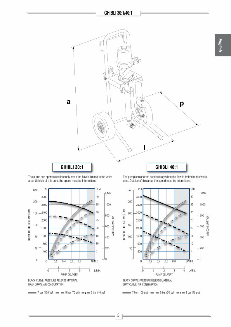
GHIBLI 30:1
O 0,2 0,4 0,6 0,8 GPM0
O 1 2 3 4 L/MIN. PUMPDELIVERY
PREs
sURE
REL
EasE
Mat
ERIa
L
BaR
200
160
120
80
40
0
PsI
3200
2800
2400
2000
1600
1200
800
400
aIR
CONs
UMPt
ION
L/MIN.
1000
800
600
400
200
0
CFM
40
35
30
25
20
15
10
5
BLaCkCURVE:PREssURERELEasEMatERIaLGRaYCURVE:aIRCONsUMPtION
7bar(100psi) 5bar(70psi) 3bar(40psi)
thepumpcanoperatecontinuouslywhentheflowislimitedtothewhitearea.Outsideofthisarea,thespeedmustbeintermittent.
GHIBLI 40:1
O 0,2 0,4 0,6 0,8 GPM0
O 1 2 3 4 L/MIN. PUMPDELIVERY
PREs
sURE
REL
EasE
Mat
ERIa
L
BaR
250
200
150
100
50
0
PsI
4000
3500
3000
2500
2000
1500
1000
500
aIR
CONs
UMPt
ION
L/MIN.
1000
800
600
400
200
0
CFM
40
35
30
25
20
15
10
5
BLaCkCURVE:PREssURERELEasEMatERIaLGRaYCURVE:aIRCONsUMPtION
7bar(100psi) 5bar(70psi) 3bar(40psi)
thepumpcanoperatecontinuouslywhentheflowislimitedtothewhitearea.Outsideofthisarea,thespeedmustbeintermittent.
6
GHIBLI 30:1/40:1
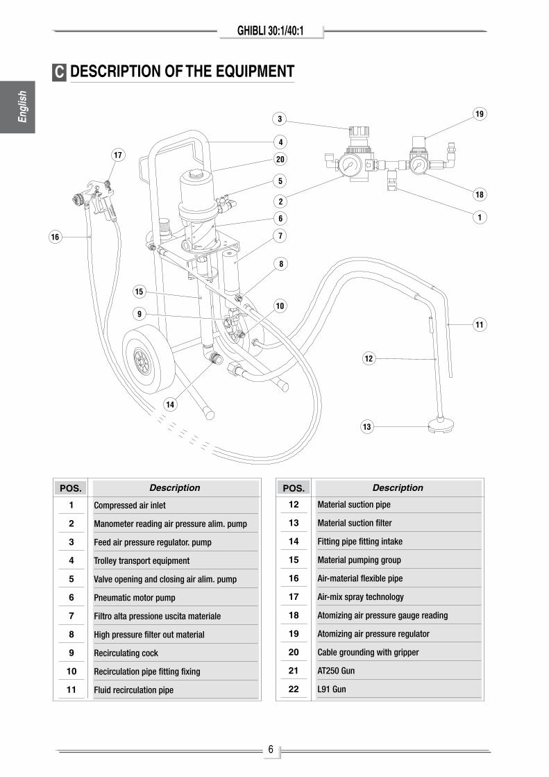
C DESCRIPTION OF THE EQUIPMENT
4
5
6
7
8
910
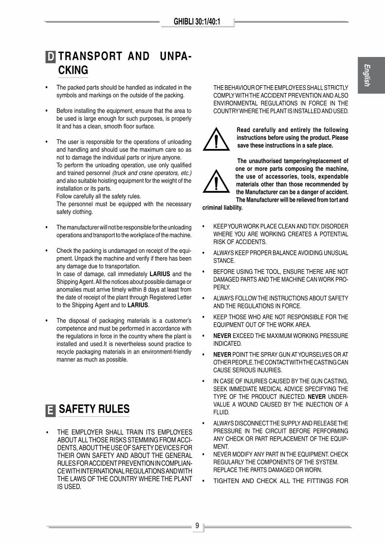
11
12
13
14
15
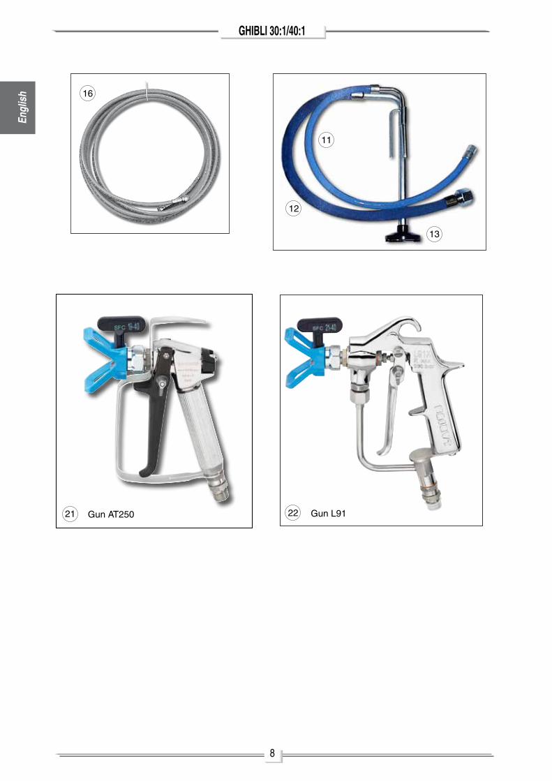
16
17
1
2
319
18
20
POS.
1
2
3
4
5
6
7
8
9
10
11
Description POS. Description
12
13
14
15
16
17
18
19
20
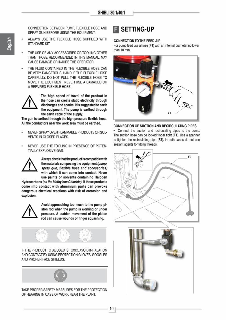
21
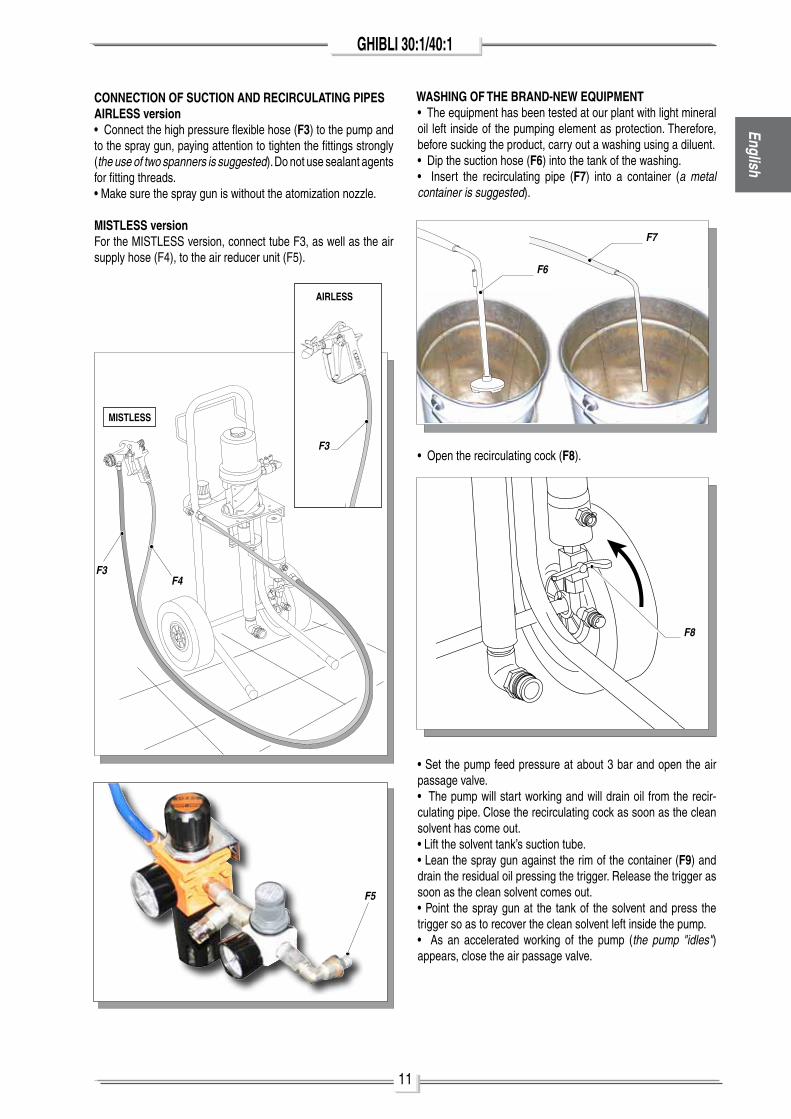
22
Compressed air inlet
Manometer reading air pressure alim. pump
Feed air pressure regulator. pump
Trolley transport equipment
Valve opening and closing air alim. pump
Pneumatic motor pump
Filtro alta pressione uscita materiale
High pressure filter out material
Recirculating cock
Recirculation pipe fitting fixing
Fluid recirculation pipe
Material suction pipe
Material suction filter
Fitting pipe fitting intake
Material pumping group
Air-material flexible pipe
Air-mix spray technology
Atomizing air pressure gauge reading
Atomizing air pressure regulator
Cable grounding with gripper
AT250 Gun
L91 Gun
Engl
ish
7
GHIBLI 30:1/40:1English
5
43
3
2
2
19
181
1
20
6
14
7
8
10
15
9
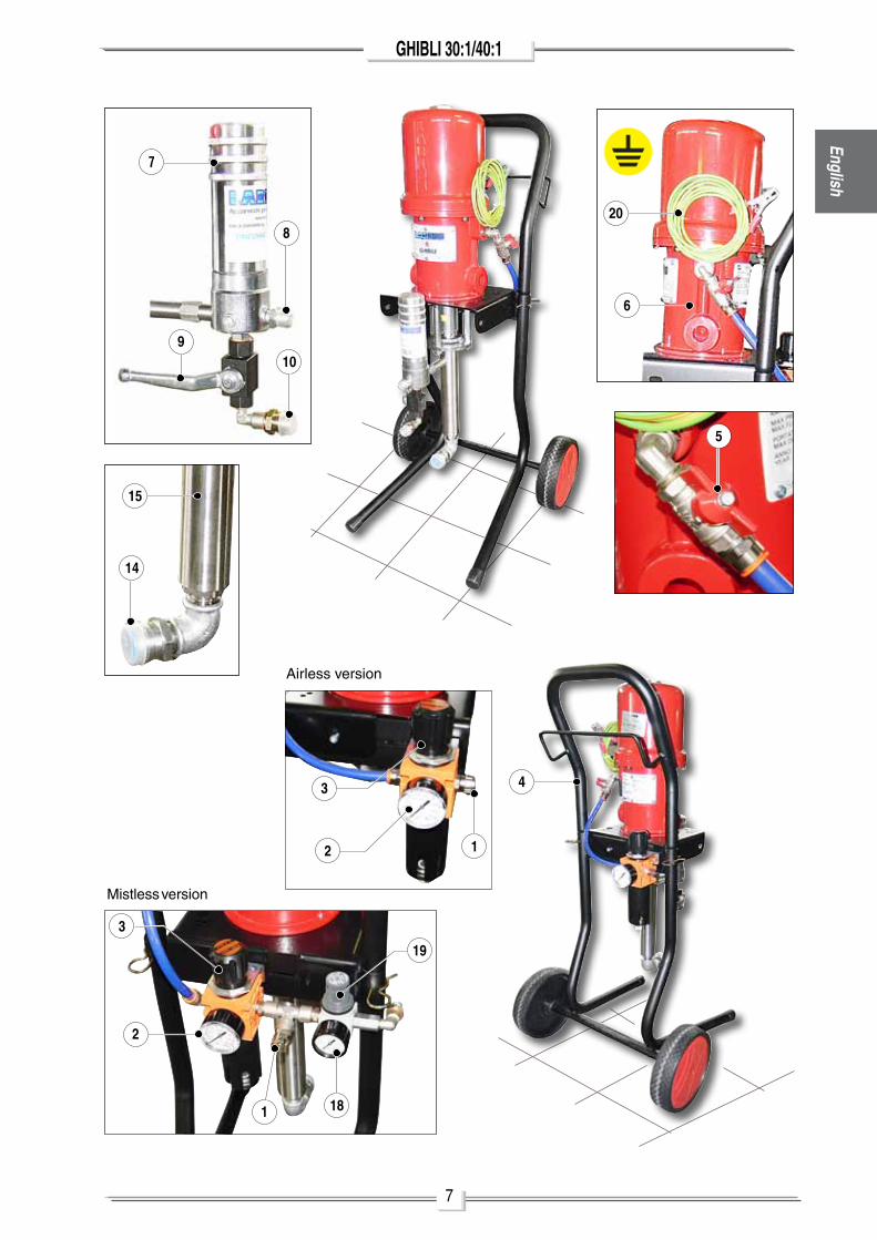
mistless version
airless version
8
GHIBLI 30:1/40:1
16
13
12
11
21 Gun aT250 22 Gun l91
Engl
ish
9
GHIBLI 30:1/40:1English
D
E
TRANSPORT AND UNPA-CKING
• The packed parts should be handled as indicated in the symbols and markings on the outside of the packing.
• Before installing the equipment, ensure that the area to be used is large enough for such purposes, is properly lit and has a clean, smooth floor surface.
• The user is responsible for the operations of unloading and handling and should use the maximum care so as not to damage the individual parts or injure anyone.
To perform the unloading operation, use only qualified and trained personnel (truck and crane operators, etc.) and also suitable hoisting equipment for the weight of the installation or its parts.
Follow carefully all the safety rules. The personnel must be equipped with the necessary
safety clothing.
• The manufacturer will not be responsible for the unloading operations and transport to the workplace of the machine.
• Check the packing is undamaged on receipt of the equi-pment. unpack the machine and verify if there has been any damage due to transportation.
In case of damage, call immediately LARIUS and the Shipping agent. all the notices about possible damage or anomalies must arrive timely within 8 days at least from the date of receipt of the plant through Registered letter to the Shipping agent and to LARIUS.
• The disposal of packaging materials is a customer’s
competence and must be performed in accordance with the regulations in force in the country where the plant is installed and used.It is nevertheless sound practice to recycle packaging materials in an environment-friendly manner as much as possible.
SAFETY RULES
• ThE EmployER Shall TRaIn ITS EmployEES aBouT all ThoSE RISKS STEmmInG FRom aCCI-DEnTS, aBouT ThE uSE oF SaFETy DEVICES FoR ThEIR oWn SaFETy anD aBouT ThE GEnERal RulES FoR aCCIDEnT pREVEnTIon In ComplIan-CE WITh InTERnaTIonal REGulaTIonS anD WITh ThE laWS oF ThE CounTRy WhERE ThE planT IS uSED.
ThE BEhaVIouR oF ThE EmployEES Shall STRICTly
Comply WITh ThE aCCIDEnT pREVEnTIon anD alSo EnVIRonmEnTal REGulaTIonS In FoRCE In ThE CounTRy WhERE ThE planT IS InSTallED anD uSED.
Read carefully and entirely the following instructions before using the product. Please save these instructions in a safe place.
The unauthorised tampering/replacement of one or more parts composing the machine, the use of accessories, tools, expendable materials other than those recommended by the Manufacturer can be a danger of accident. The Manufacturer will be relieved from tort and
criminal liability.
• KEEp youR WoRK plaCE ClEan anD TIDy. DISoRDER WhERE you aRE WoRKInG CREaTES a poTEnTIal RISK oF aCCIDEnTS.
• alWayS KEEp pRopER BalanCE aVoIDInG unuSual STanCE.
• BEFoRE uSInG ThE Tool, EnSuRE ThERE aRE noT DamaGED paRTS anD ThE maChInE Can WoRK pRo-pERly.
• alWayS FolloW ThE InSTRuCTIonS aBouT SaFETy anD ThE REGulaTIonS In FoRCE.
• KEEp ThoSE Who aRE noT RESponSIBlE FoR ThE EQuIpmEnT ouT oF ThE WoRK aREa.
• NEVER EXCEED ThE maXImum WoRKInG pRESSuRE InDICaTED.
• NEVER poInT ThE SpRay Gun aT youRSElVES oR aT oThER pEoplE. ThE ConTaCT WITh ThE CaSTInG Can CauSE SERIouS InJuRIES.
• In CaSE oF InJuRIES CauSED By ThE Gun CaSTInG, SEEK ImmEDIaTE mEDICal aDVICE SpECIFyInG ThE TypE oF ThE pRoDuCT InJECTED. NEVER unDER-ValuE a WounD CauSED By ThE InJECTIon oF a FluID.
• alWayS DISConnECT ThE Supply anD RElEaSE ThE pRESSuRE In ThE CIRCuIT BEFoRE pERFoRmInG any ChECK oR paRT REplaCEmEnT oF ThE EQuIp-mEnT.
• nEVER moDIFy any paRT In ThE EQuIpmEnT. ChECK REGulaRly ThE ComponEnTS oF ThE SySTEm.
REplaCE ThE paRTS DamaGED oR WoRn.
• TIGhTEn anD ChECK all ThE FITTInGS FoR
10
GHIBLI 30:1/40:1
F SETTING-UP
CONNECTION TO THE FEED AIRFor pump feed use a hose (F1) with an internal diameter no lower than 10 mm.
CONNECTION OF SUCTION AND RECIRCULATING PIPES• Connect the suction and recirculating pipes to the pump.The suction hose can be locked finger tight (F1). use a spanner to tighten the recirculating pipe (F2). In both cases do not use sealant agents for fitting threads.
F1
F2
F1
TaKE pRopER SaFETy mEaSuRES FoR ThE pRoTECTIon oF hEaRInG In CaSE oF WoRK nEaR ThE planT.
ConnECTIon BETWEEn pump, FlEXIBlE hoSE anD SpRay Gun BEFoRE uSInG ThE EQuIpmEnT.
• alWayS uSE ThE FlEXIBlE hoSE SupplIED WITh STanDaRD KIT.
• ThE uSE oF any aCCESSoRIES oR ToolInG oThER Than ThoSE RECommEnDED In ThIS manual, may CauSE DamaGE oR InJuRE ThE opERaToR.
• ThE FluID ConTaInED In ThE FlEXIBlE hoSE Can BE VERy DanGERouS. hanDlE ThE FlEXIBlE hoSE CaREFully. Do noT pull ThE FlEXIBlE hoSE To moVE ThE EQuIpmEnT. nEVER uSE a DamaGED oR a REpaIRED FlEXIBlE hoSE.
The high speed of travel of the product in the hose can create static electricity through discharges and sparks. It is suggested to earth the equipment. The pump is earthed through the earth cable of the supply.
The gun is earthed through the high pressure flexible hose. All the conductors near the work area must be earthed.
• nEVER SpRay oVER FlammaBlE pRoDuCTS oR Sol-VEnTS In CloSED plaCES.
• nEVER uSE ThE ToolInG In pRESEnCE oF poTEn-TIally EXploSIVE GaS.
Always check that the product is compatible with the materials composing the equipment (pump, spray gun, flexible hose and accessories) with which it can come into contact. Never use paints or solvents containing Halogen
Hydrocarbons (as the Methylene Chloride). If these products come into contact with aluminium parts can provoke dangerous chemical reactions with risk of corrosion and explosion.
Avoid approaching too much to the pump pi-ston rod when the pump is working or under pressure. A sudden movement of the piston rod can cause wounds or finger squashing.
IF ThE pRoDuCT To BE uSED IS ToXIC, aVoID InhalaTIon anD ConTaCT By uSInG pRoTECTIon GloVES, GoGGlES anD pRopER FaCE ShIElDS.
Engl
ish
11
GHIBLI 30:1/40:1English
CONNECTION OF SUCTION AND RECIRCULATING PIPESAIRLESS version• Connect the high pressure flexible hose (F3) to the pump and to the spray gun, paying attention to tighten the fittings strongly (the use of two spanners is suggested). Do not use sealant agents for fitting threads.• make sure the spray gun is without the atomization nozzle.
MISTLESS versionFor the mISTlESS version, connect tube F3, as well as the air supply hose (F4), to the air reducer unit (F5).
WASHING OF THE BRAND-NEW EQUIPMENT• The equipment has been tested at our plant with light mineral oil left inside of the pumping element as protection. Therefore, before sucking the product, carry out a washing using a diluent.• Dip the suction hose (F6) into the tank of the washing.• Insert the recirculating pipe (F7) into a container (a metal container is suggested).
MISTLESS
F5
F3
F3F4
• open the recirculating cock (F8).
F7
F6
F8
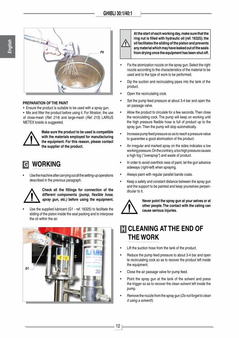
• Set the pump feed pressure at about 3 bar and open the air passage valve.• The pump will start working and will drain oil from the recir-culating pipe. Close the recirculating cock as soon as the clean solvent has come out.• lift the solvent tank’s suction tube.• lean the spray gun against the rim of the container (F9) and drain the residual oil pressing the trigger. Release the trigger as soon as the clean solvent comes out.• point the spray gun at the tank of the solvent and press the trigger so as to recover the clean solvent left inside the pump.• as an accelerated working of the pump (the pump "idles") appears, close the air passage valve.
AIRLESS
12
GHIBLI 30:1/40:1
• allow the product to circulate for a few seconds. Then close the recirculating cock. The pump will keep on working until the high pressure flexible hose is full of product up to the spray gun. Then the pump will stop automatically.
• Increase pump feed pressure so as to reach a pressure value to guarantee a good atomization of the product.
• an irregular and marked spray on the sides indicates a low working pressure. on the contrary, a too high pressure causes a high fog ("overspray") and waste of product.
• In order to avoid overthick ness of paint, let the gun advance sideways (right-left) when spraying.
• always paint with regular parallel bands coats.
• Keep a safety and constant distance between the spray gun and the support to be painted and keep yourselves perpen-dicular to it.
Never point the spray gun at your selves or at other people. The contact with the cating can cause serious injuries.
H CLEANING AT THE END OF THE WORK
• lift the suction hose from the tank of the product.
• Reduce the pump feed pressure to about 3-4 bar and open te recirculating cock so as to recover the product left inside the equipment.
• Close the air passage valve for pump feed.
• point the spray gun at the tank of the solvent and press the trigger so as to recover the clean solvent left inside the pump.
• Remove the nozzle from the spray gun (Do not forget to clean it using a solvent!).
PREPARATION OF THE PAINT• Ensure the product is suitable to be used with a spray gun.• mix and filter the product before using it. For filtration, the use of close-mesh (Ref. 214) and large-mesh (Ref. 215) laRIuS mETEX braids is suggested.
Make sure the product to be used is compatible with the materials employed for manufacturing the equipment. For this reason, please contact the supplier of the product.
G WORKING• use the machine after carrying out all the setting-up operations
described in the previous paragraph.
Check all the fittings for connection of the different components (pump, flexible hose, spray gun, etc.) before using the equipment.
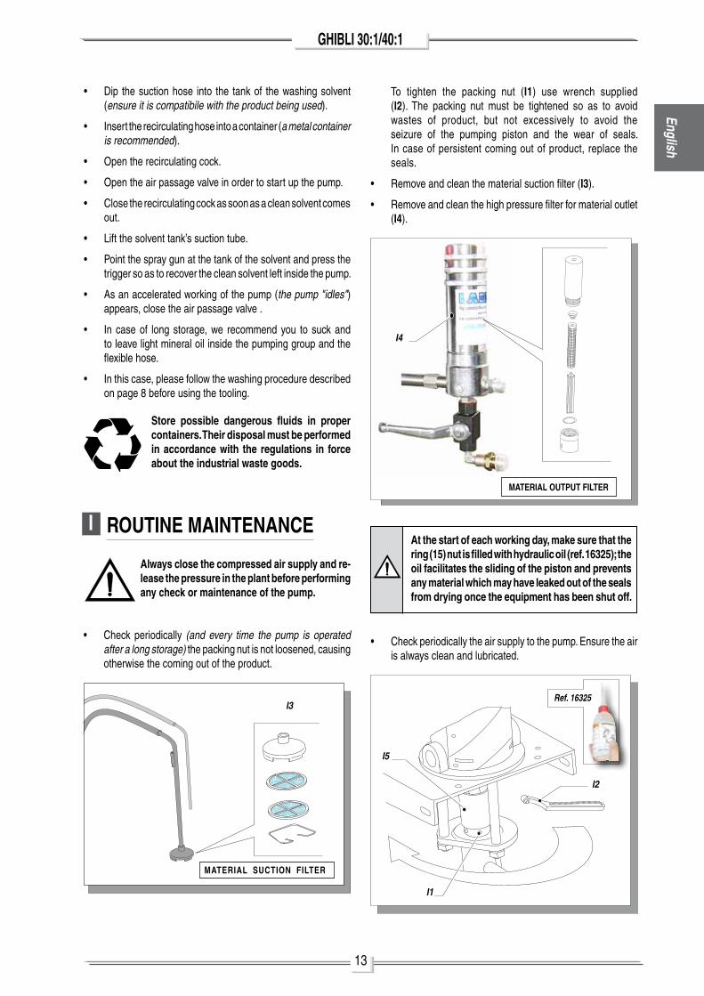
• use the supplied lubricant (G1 - ref. 16325) to facilitate the sliding of the piston inside the seal packing and to interpose the oil within the air.
At the start of each working day, make sure that the ring nut is filled with hydraulic oil (ref. 16325); the oil facilitates the sliding of the piston and prevents any material which may have leaked out of the seals from drying once the equipment has been shut off.
• Fix the atomization nozzle on the spray gun. Select the right nozzle according to the characteristics of the material to be used and to the type of work to be performed.
• Dip the suction and recirculating pipes into the tank of the product.
• open the recirculating cock.
• Set the pump feed pressure at about 3-4 bar and open the air passage valve.
Engl
ish
F9
G1
13
GHIBLI 30:1/40:1English
I ROUTINE MAINTENANCE
Always close the compressed air supply and re-lease the pressure in the plant before performing any check or maintenance of the pump.
• Check periodically (and every time the pump is operated after a long storage) the packing nut is not loosened, causing otherwise the coming out of the product.
I2
I1
I5
• Dip the suction hose into the tank of the washing solvent (ensure it is compatibile with the product being used).
• Insert the recirculating hose into a container (a metal container is recommended).
• open the recirculating cock.
• open the air passage valve in order to start up the pump.
• Close the recirculating cock as soon as a clean solvent comes out.
• lift the solvent tank’s suction tube.
• point the spray gun at the tank of the solvent and press the trigger so as to recover the clean solvent left inside the pump.
• as an accelerated working of the pump (the pump "idles") appears, close the air passage valve .
• In case of long storage, we recommend you to suck and to leave light mineral oil inside the pumping group and the flexible hose.
• In this case, please follow the washing procedure described on page 8 before using the tooling.
Store possible dangerous fluids in proper containers. Their disposal must be performed in accordance with the regulations in force about the industrial waste goods.
MATERIAL SUCTION FILTER
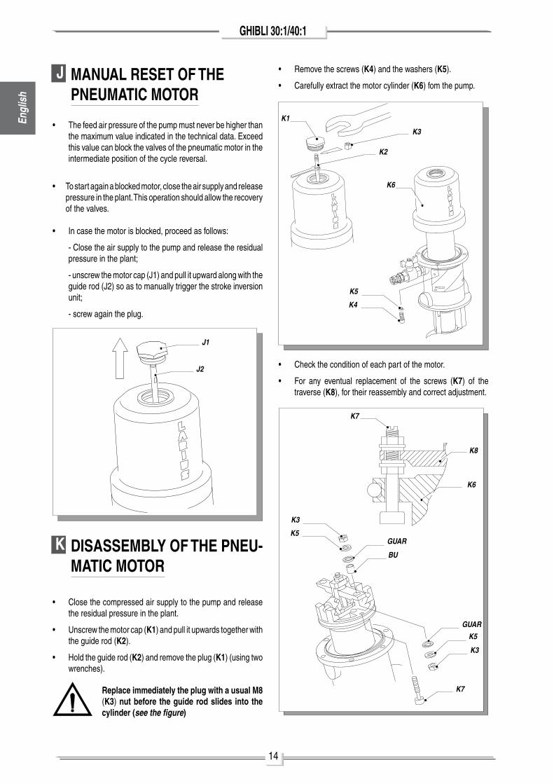
To tighten the packing nut (I1) use wrench supplied (I2). The packing nut must be tightened so as to avoid wastes of product, but not excessively to avoid the seizure of the pumping piston and the wear of seals. In case of persistent coming out of product, replace the seals.
• Remove and clean the material suction filter (I3).
• Remove and clean the high pressure filter for material outlet (I4).
• Check periodically the air supply to the pump. Ensure the air is always clean and lubricated.
At the start of each working day, make sure that the ring (15) nut is filled with hydraulic oil (ref. 16325); the oil facilitates the sliding of the piston and prevents any material which may have leaked out of the seals from drying once the equipment has been shut off.
Ref. 16325I3
MATERIAL OUTPUT FILTER
I4
14
GHIBLI 30:1/40:1
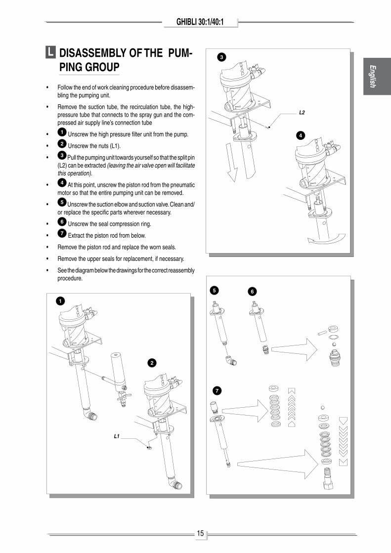
K DISASSEMBLY OF THE PNEU-MATIC MOTOR
• Close the compressed air supply to the pump and release the residual pressure in the plant.
• unscrew the motor cap (K1) and pull it upwards together with the guide rod (K2).
• hold the guide rod (K2) and remove the plug (K1) (using two wrenches).
Replace immediately the plug with a usual M8 (K3) nut before the guide rod slides into the cylinder (see the figure)
• Remove the screws (K4) and the washers (K5).
• Carefully extract the motor cylinder (K6) fom the pump.
K1
K2
K3
K4
K5
K6
K7
K7
K6
K8
K5
K3
K5
K3
GUAR
BU
GUAR
J MANUAL RESET OF THE PNEUMATIC MOTOR
• The feed air pressure of the pump must never be higher than the maximum value indicated in the technical data. Exceed this value can block the valves of the pneumatic motor in the intermediate position of the cycle reversal.
• To start again a blocked motor, close the air supply and release pressure in the plant. This operation should allow the recovery of the valves.
• In case the motor is blocked, proceed as follows:
- Close the air supply to the pump and release the residual pressure in the plant;
- unscrew the motor cap (J1) and pull it upward along with the guide rod (J2) so as to manually trigger the stroke inversion unit;
- screw again the plug.
J1
J2 • Check the condition of each part of the motor.
• For any eventual replacement of the screws (K7) of the traverse (K8), for their reassembly and correct adjustment.
Engl
ish
15
GHIBLI 30:1/40:1English
L DISASSEMBLY OF THE PUM-PING GROUP
• Follow the end of work cleaning procedure before disassem-bling the pumping unit.
• Remove the suction tube, the recirculation tube, the high-pressure tube that connects to the spray gun and the com-pressed air supply line’s connection tube
• 1 unscrew the high pressure filter unit from the pump.
• 2 unscrew the nuts (l1).
• 3 pull the pumping unit towards yourself so that the split pin (l2) can be extracted (leaving the air valve open will facilitate this operation).
• 4 at this point, unscrew the piston rod from the pneumatic motor so that the entire pumping unit can be removed.
• 5 unscrew the suction elbow and suction valve. Clean and/or replace the specific parts wherever necessary.
• 6 unscrew the seal compression ring.
• 7 Extract the piston rod from below.
• Remove the piston rod and replace the worn seals.
• Remove the upper seals for replacement, if necessary.
• See the diagram below the drawings for the correct reassembly procedure.
L1
L2
3
4
5 6
7
2
1
16
GHIBLI 30:1/40:1
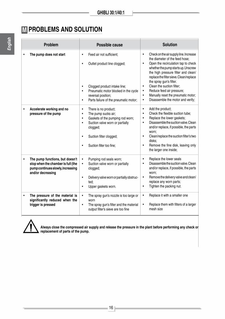
M PROBLEMS AND SOLUTION
SolutionPossible causeProblem
• The pump does not start
• Accelerate working and no pressure of the pump
• The pump functions, but doesn't stop when the chamber is full (the pump continues slowly, increasing and/or decreasing
• The pressure of the material is significantly reduced when the trigger is pressed
• Feed air not sufficient;
• outlet product line clogged;
• Clogged product intake line;• pneumatic motor blocked in the cycle
reversal position;• parts failure of the pneumatic motor;
• There is no product; • The pump sucks air;• Gaskets of the pumping rod worn;• Suction valve worn or partially clogged;
• Suction filter clogged;
• Suction filter too fine;
• pumping rod seals worn;• Suction valve worn or partially clogged;
• Delivery valve worn or partially obstruc-ted;
• upper gaskets worn.
• The spray gun’s nozzle is too large or worn
• The spray gun’s filter and the material output filter’s sieve are too fine
• Check on the air supply line. Increase the diameter of the feed hose;
• open the recirculation tap to check whether the pump starts up. unscrew the high pressure filter and clean/replace the filter sieve. Clean/replace the spray gun’s filter.
• Clean the suction filter;• Reduce feed air pressure;• manually reset the pneumatic motor;• Disassemble the motor and verify;
• add the product;• Check the flexible suction tube;• Replace the lower gaskets;• Disassemble the suction valve. Clean
and/or replace, if possible, the parts worn;
• Clean/replace the suction filter’s two disks;
• Remove the fine disk, leaving only the larger one inside;
• Replace the lower seals• Disassemble the suction valve. Clean
and/or replace, if possible, the parts worn;
• Remove the delivery valve and clean/replace any worn parts;
• Tighten the packing nut.
• Replace it with a smaller one
• Replace them with filters of a larger mesh size
Always close the compressed air supply and release the pressure in the plant before performing any check or replacement of parts of the pump.
Engl
ish
17
GHIBLI 30:1/40:1English
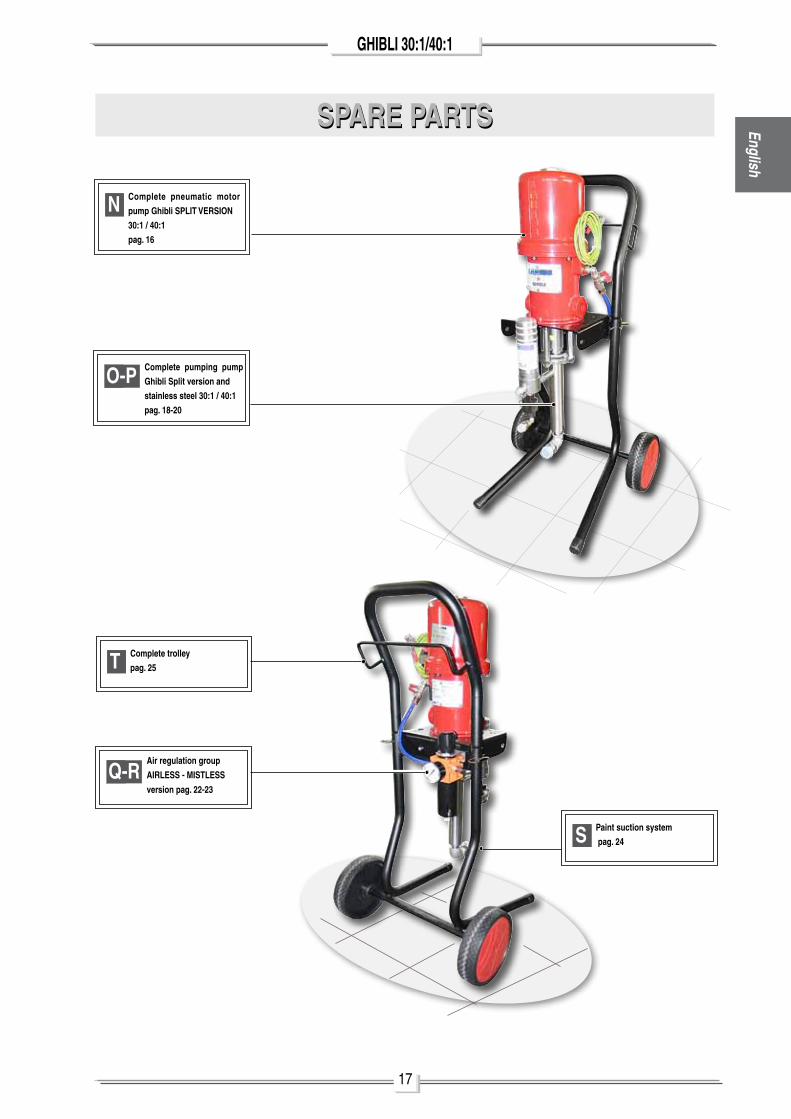
SPARE PARTSSPARE PARTS
ON Complete pneumatic motor
pump Ghibli SPLIT VERSION
30:1 / 40:1
pag. 16
OT Complete trolley
pag. 25
OS Paint suction system
pag. 24
OQ-RAir regulation group
AIRLESS - MISTLESS
version pag. 22-23
Complete pumping pump
Ghibli Split version and
stainless steel 30:1 / 40:1
pag. 18-20
OO-P
18
GHIBLI 30:1/40:1
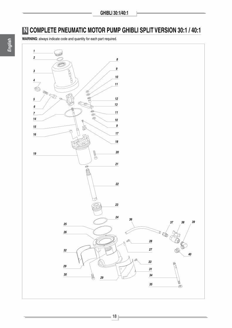
N COMPLETE PNEUMATIC MOTOR PUMP GHIBLI SPLIT VERSION 30:1 / 40:1
2
1
39
9
10
10
11
11
12
13
17
18
4
5
6
7
8
14
15
16
20
21
22
23
19
24
25
27
29
30
26
31
33
32
2934
35
28
3637 38 39
40
WARNING: always indicate code and quantity for each part required.
Engl
ish
19
GHIBLI 30:1/40:1English
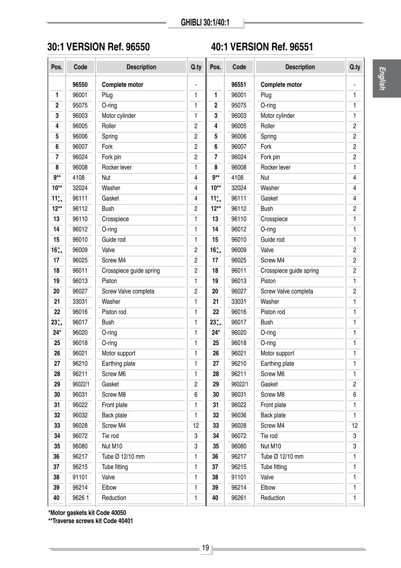
*Motor gaskets kit Code 40050**Traverse screws kit Code 40401
Pos.
Complete motor
plug
o-ring
motor cylinder
Roller
Spring
Fork
Fork pin
Rocker lever
nut
Washer
Gasket
Bush
Crosspiece
o-ring
Guide rod
Valve
Screw m4
Crosspiece guide spring
piston
Screw Valve completa
Washer
piston rod
Bush
o-ring
o-ring
motor support
Earthing plate
Screw m6
Gasket
Screw m8
Front plate
Back plate
Screw m4
Tie rod
nut m10
Tube Ø 12/10 mm
Tube fitting
Valve
Elbow
Reduction
Code Description
,
1
2
3
4
5
6
7
8
9**
10**
11
12**
13
14
15
16
17
18
19
20
21
22
23
24*
25
26
27
28
29
30
31
32
33
34
35
36
37
38
39
40
Q.ty
-
1
1
1
2
2
2
2
1
4
4
4
2
1
1
1
2
2
2
1
2
1
1
1
1
1
1
1
1
2
6
1
1
12
3
3
1
1
1
1
1
96550
96001
95075
96003
96005
96006
96007
96024
96008
4108
32024
96111
96112
96110
96012
96010
96009
96025
96011
96013
96027
33031
96016
96017
96020
96018
96021
96210
96211
96022/1
96031
96022
96032
96028
96072
96080
96217
96215
91101
96214
9626 1
***
30:1 VERSION Ref. 96550
***
***
Pos.
Complete motor
plug
o-ring
motor cylinder
Roller
Spring
Fork
Fork pin
Rocker lever
nut
Washer
Gasket
Bush
Crosspiece
o-ring
Guide rod
Valve
Screw m4
Crosspiece guide spring
piston
Screw Valve completa
Washer
piston rod
Bush
o-ring
o-ring
motor support
Earthing plate
Screw m6
Gasket
Screw m8
Front plate
Back plate
Screw m4
Tie rod
nut m10
Tube Ø 12/10 mm
Tube fitting
Valve
Elbow
Reduction
Code Description
,
1
2
3
4
5
6
7
8
9**
10**
11
12**
13
14
15
16
17
18
19
20
21
22
23
24*
25
26
27
28
29
30
31
32
33
34
35
36
37
38
39
40
Q.ty
-
1
1
1
2
2
2
2
1
4
4
4
2
1
1
1
2
2
2
1
2
1
1
1
1
1
1
1
1
2
6
1
1
12
3
3
1
1
1
1
1
96551
96001
95075
96003
96005
96006
96007
96024
96008
4108
32024
96111
96112
96110
96012
96010
96009
96025
96011
96013
96027
33031
96016
96017
96020
96018
96021
96210
96211
96022/1
96031
96022
96036
96028
96072
96080
96217
96215
91101
96214
96261
***
***
***
40:1 VERSION Ref. 96551
20
GHIBLI 30:1/40:1
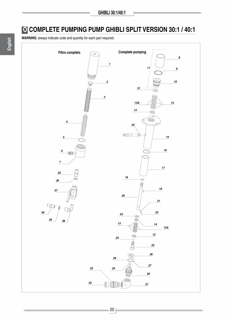
O COMPLETE PUMPING PUMP GHIBLI SPLIT VERSION 30:1 / 40:1
8
10
12
13
14
15
18
19
20
11
23
1413
1224
25
2628
27
30
29
31
32
33
34
9
16
17
22
21
13A
13A
1
2
3
4
5
6
7
35
36
37
3836
39
WARNING: always indicate code and quantity for each part required.
Filtro completo Complete pumping
Engl
ish
21
GHIBLI 30:1/40:1English
*Spare part kit Code 40055
Complete pumpingoil tanko-ringGaskets ring nutComplete tankV female ringTeflon gasketpolyethylene gasketV male ringpumping groupGasketSleeveo-ringWasherpiston rodpinElastic ringWasherBall ø5/16"pumping pistonRingpino-ringBall ø 1/2"Suction valveElbowSuction hose fittingSleeve Filter fitting
-1111264211111112111111111111
*Spare part kit Code 40060
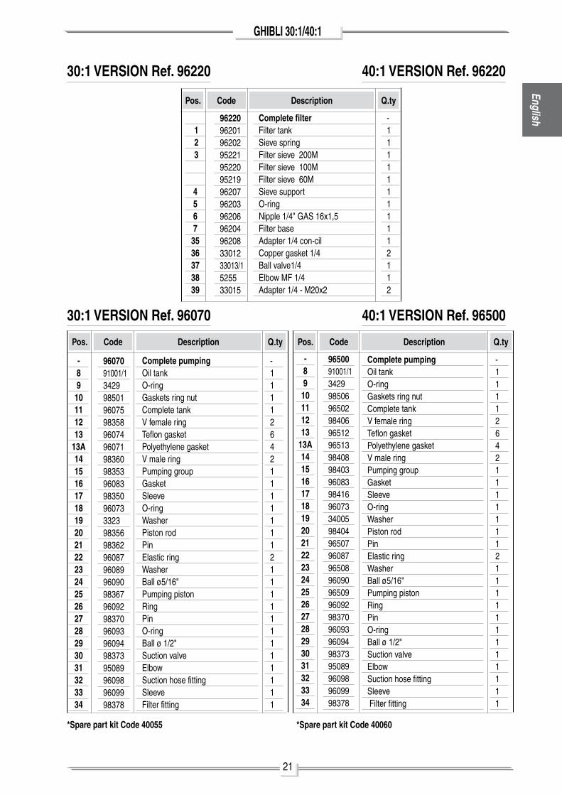
30:1 VERSION Ref. 96220
30:1 VERSION Ref. 96070
Pos. Code Description Q.ty
Complete pumpingoil tanko-ringGaskets ring nutComplete tankV female ringTeflon gasketpolyethylene gasketV male ringpumping groupGasketSleeveo-ringWasherpiston rodpinElastic ringWasherBall ø5/16"pumping pistonRingpino-ringBall ø 1/2"Suction valveElbowSuction hose fittingSleeve Filter fitting
Pos. Code Description Q.ty
-1111264211111112111111111111
9650091001/134299850696502984069651296513984089840396083984169607334005984049650796087965089609096509960929837096093960949837395089960989609998378
40:1 VERSION Ref. 96220
40:1 VERSION Ref. 96500
Pos. Code Description Q.ty
-8910111213
13A141516171819202122232425262728293031323334
9607091001/13429985019607598358960749607198360983539608398350960733323983569836296087960899609098367960929837096093960949837395089960989609998378
-8910111213
13A141516171819202122232425262728293031323334
Complete filterFilter tankSieve springFilter sieve 200mFilter sieve 100mFilter sieve 60mSieve supporto-ringnipple 1/4" GaS 16x1,5Filter baseadapter 1/4 con-cil Copper gasket 1/4Ball valve1/4Elbow mF 1/4adapter 1/4 - m20x2
-11111111112112
, 1 2 3
45673536373839
96220962019620295221952209521996207962039620696204962083301233013/1525533015

22
GHIBLI 30:1/40:1
P COMPLETE PUMPING PUMP GHIBLI SPLIT VERSION STAINLESS 30:1/40:1WARNING: always indicate code and quantity for each part required.
8
10
12
13
14
15
18
19
20
11
23
1413
1224
25
2628
27
30
29
31
32
33
34
9
16
17
22
21
13A
13A
1
2
3
4
5
6
7
35
36
37
3836
39
Filtro completo Complete pumping
Engl
ish
23
GHIBLI 30:1/40:1English
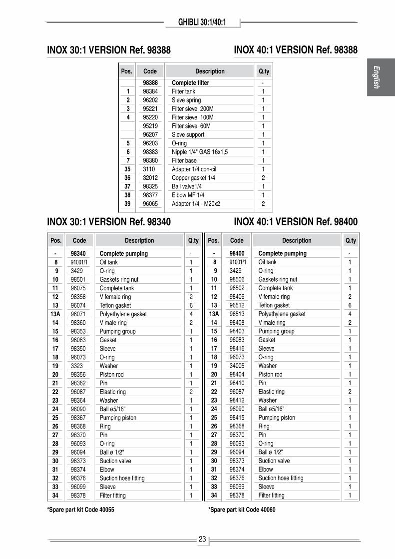
COMPLETE PUMPING PUMP GHIBLI SPLIT VERSION STAINLESS 30:1/40:1
*Spare part kit Code 40055
Complete pumpingoil tanko-ringGaskets ring nutComplete tankV female ringTeflon gasketpolyethylene gasketV male ringpumping groupGasketSleeveo-ringWasherpiston rodpinElastic ringWasherBall ø5/16"pumping pistonRingpino-ringBall ø 1/2"Suction valveElbowSuction hose fittingSleeve Filter fitting
- 8 910111213
13A141516171819202122232425262728293031323334
-1111264211111112111111111111
9834091001/13429985019607598358960749607198360983539608398350960733323983569836296087983649609098367983689837096093960949837398374983769609998378
*Spare part kit Code 40060
INOX 30:1 VERSION Ref. 98388
INOX 30:1 VERSION Ref. 98340
Pos. Code Description Q.ty
Complete pumpingoil tanko-ringGaskets ring nutComplete tankV female ringTeflon gasketpolyethylene gasketV male ringpumping groupGasketSleeveo-ringWasherpiston rodpinElastic ringWasherBall ø5/16"pumping pistonRingpino-ringBall ø 1/2"Suction valveElbowSuction hose fittingSleeve Filter fitting
- 8 910111213
13A141516171819202122232425262728293031323334
Pos. Code Description Q.ty
-1111264211111112111111111111
9840091001/134299850696502984069651296513984089840396083984169607334005984049841096087984129609098415983689837096093960949837398374983769609998378
INOX 40:1 VERSION Ref. 98388
INOX 40:1 VERSION Ref. 98400
Pos. Code Description Q.ty
Complete filterFilter tankSieve springFilter sieve 200mFilter sieve 100mFilter sieve 60mSieve supporto-ringnipple 1/4" GaS 16x1,5Filter baseadapter 1/4 con-cil Copper gasket 1/4Ball valve1/4Elbow mF 1/4adapter 1/4 - m20x2
, 1 2 3 4
5 6 73536373839
-11111111112112
98388983849620295221952209521996207962039838398380311032012983259837796065
24
GHIBLI 30:1/40:1
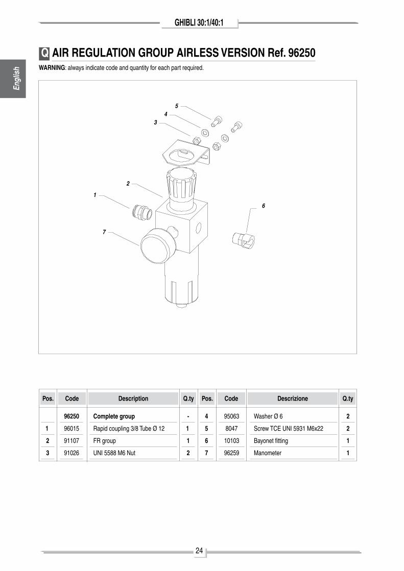
Pos.
Complete group
Rapid coupling 3/8 Tube Ø 12
FR group
unI 5588 m6 nut
Code Description
1.
2
3
Q.ty
-
1.
1
2
Pos. Code Descrizione Q.ty
4
5
6
7
Washer Ø 6
Screw TCE unI 5931 m6x22
Bayonet fitting
manometer
2
2
1
1
96250
96015
91107
91026
95063
8047
10103
96259
Q AIR REGULATION GROUP AIRLESS VERSION Ref. 96250WARNING: always indicate code and quantity for each part required.
1
2
34
5
6
7
Engl
ish
25
GHIBLI 30:1/40:1English
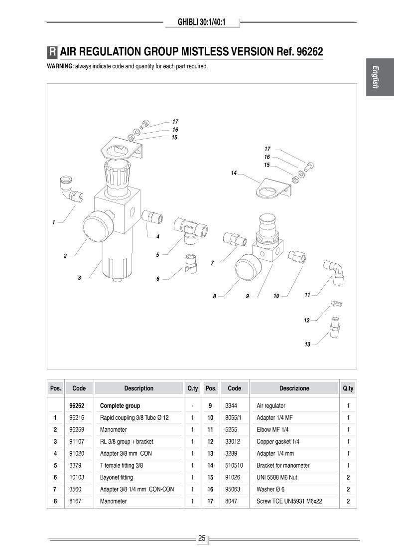
Pos.
Complete group
Rapid coupling 3/8 Tube Ø 12
manometer
Rl 3/8 group + bracket
adapter 3/8 mm Con
T female fitting 3/8
Bayonet fitting
adapter 3/8 1/4 mm Con-Con
manometer
Code Description
1
2
3
4
5,
6
7,
8
Q.ty
-
1
1
1
1
1
1
1
1
Pos. Code Descrizione Q.ty
9
10
11
12
13
14
15
16
17
air regulator
adapter 1/4 mF
Elbow mF 1/4
Copper gasket 1/4
adapter 1/4 mm
Bracket for manometer
unI 5588 m6 nut
Washer Ø 6
Screw TCE unI5931 m6x22
1
1
1
1
1
1
2
2
2
96262
96216
96259
91107
91020
3379
10103
3560
8167
3344
8055/1
5255
33012
3289
510510
91026
95063
8047
R AIR REGULATION GROUP MISTLESS VERSION Ref. 96262WARNING: always indicate code and quantity for each part required.
9
1
2
3
4
5
6
10
7
118
12
13
151617
14
171615
26
GHIBLI 30:1/40:1
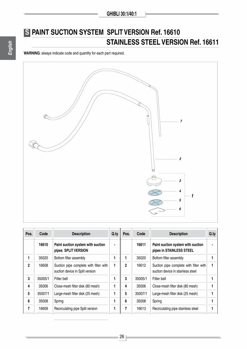
Pos.
Paint suction system with suction pipes SPLIT VERSION
Bottom filter assembly
Suction pipe complete with filter with suction device in Split version
Filter bell
Close-mesh filter disk (80 mesh)
large-mesh filter disk (25 mesh)
Spring
Recirculating pipe Split version
Code Description
1
2
3
4
5
6
7
Q.ty
-
1
1
1
1
1
1
1
Pos. Code Description Q.ty
1
2
3
4
5
6
7
Paint suction system with suction pipes in STAINLESS STEEL
Bottom filter assembly
Suction pipe complete with filter with suction device in stainless steel
Filter bell
Close-mesh filter disk (80 mesh)
large-mesh filter disk (25 mesh)
Spring
Recirculating pipe stainless steel
-
1
1
1
1
1
1
1
16610
35020
16608
35005/1
35006
35007/1
35008
16609
16611
35020
16612
35005/1
35006
35007/1
35008
16613
S PAINT SUCTION SYSTEM SPLIT VERSION Ref. 16610 STAINLESS STEEL VERSION Ref. 16611
WARNING: always indicate code and quantity for each part required.
7
2
3
4
5
6
1
Engl
ish
27
GHIBLI 30:1/40:1English
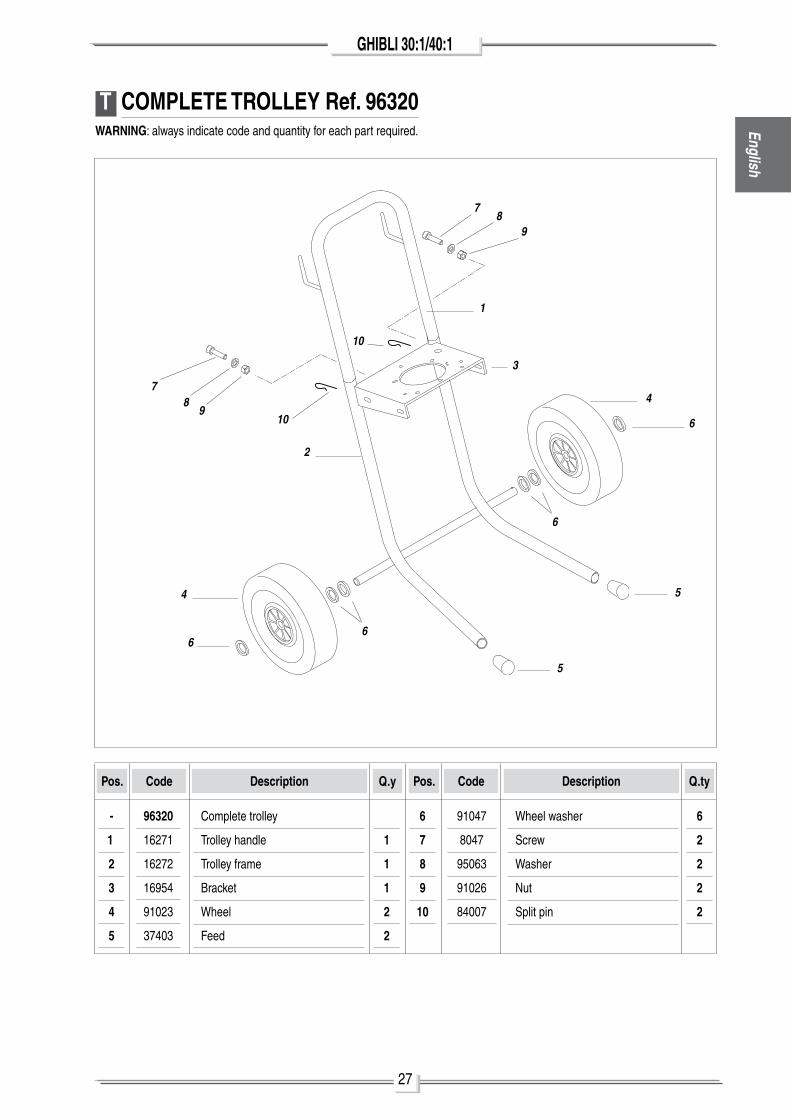
T COMPLETE TROLLEY Ref. 96320WARNING: always indicate code and quantity for each part required.
7
2
3
4
5
6
1
6
89
Pos.
Complete trolley
Trolley handle
Trolley frame
Bracket
Wheel
Feed
Code Description
-
1.
2
3
4
5
Q.y
1
1
1
2
2
Pos. Code Description Q.ty
6
7
8
9
10
Wheel washer
Screw
Washer
nut
Split pin
6
2
2
2
2
96320
16271
16272
16954
91023
37403
91047
8047
95063
91026
84007
10
10
78
9
6
4
6
5
28
GHIBLI 30:1/40:1
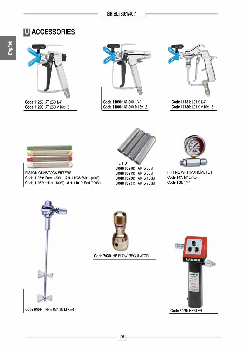
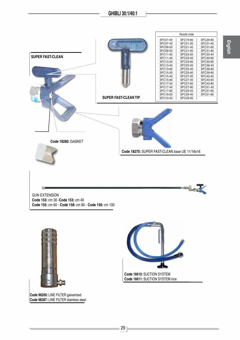
U ACCESSORIES
pISTon GunSToCK FIlTERSCode 11039: Green (30m) - Art. 11038: White (60m)Code 11037: yellow (100m) - Art. 11019: Red (200m)
FIlTRoCode 95218: TamIS 30mCode 95219: TamIS 60mCode 95220: TamIS 100mCode 95221: TamIS 200m
FITTInG WITh manomETERCode 147: m16x1,5Code 150: 1/4"
Code 91044: pnEumaTIC mIXER
Code 7030: hp FloW REGulaToR
Code 6099: hEaTER
Code 11250: aT 250 1/4"Code 11200: aT 250 m16x1,5
Code 11090: aT 300 1/4"Code 11000: aT 300 m16x1,5
Code 11131: l91X 1/4"Code 11130: l91X m16x1,5
Engl
ish
29
GHIBLI 30:1/40:1English
Code 18270: SupER FaST-ClEan base uE 11/16x16
Code 18280: GaSKET
SUPER FAST-CLEAN TIP
SUPER FAST-CLEAN
nozzle code
SFC07-20SFC07-40SFC09-20SFC09-40SFC11-20SFC11-40SFC13-20SFC13-40SFC13-60SFC15-20SFC15-40SFC15-60SFC17-20SFC17-40SFC17-60SFC19-20SFC19-40
SFC19-60SFC21-20SFC21-40SFC21-60SFC23-20SFC23-40SFC23-60SFC25-20SFC25-40SFC25-60SFC27-20SFC27-40SFC27-60SFC27-80SFC29-20SFC29-40SFC29-60
SFC29-80SFC31-40SFC31-60SFC31-80SFC33-40SFC33-60SFC33-80SFC39-40SFC39-60SFC39-80SFC43-40SFC43-60SFC43-80SFC51-40SFC51-60SFC51-80
Code 16610: SuCTIon SySTEmCode 16611: SuCTIon SySTEm inox
Code 96200: lInE FIlTER galvanizedCode 98387: lInE FIlTER stainless steel
Gun EXTEnSIonCode 153: cm 30 -Code 153: cm 40 Code 155: cm 60 - Code 158: cm 80 - Code 156: cm 100
30
GHIBLI 30:1/40:1
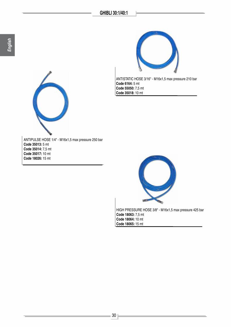
hIGh pRESSuRE hoSE 3/8" - m16x1,5 max pressure 425 barCode 18063: 7,5 mtCode 18064: 10 mtCode 18065: 15 mt
anTISTaTIC hoSE 3/16" - m16x1,5 max pressure 210 barCode 6164: 5 mtCode 55050: 7,5 mtCode 35018: 10 mt
anTIpulSE hoSE 1/4" - m16x1,5 max pressure 250 barCode 35013: 5 mtCode 35014: 7,5 mtCode 35017: 10 mtCode 18026: 15 mt
Engl
ish
31
GHIBLI 30:1/40:1English
V
W
DESCRIPTIONThese safety instructions refer to the installation, use and mainte-nance of laRIuS GhIBlI series pneumatic piston transfer pumps in high risk environments where potentially explosive gasses or vapours are present.
These instructions, along with the indica-tions provided in the user and maintenance manual, must be fully respected.
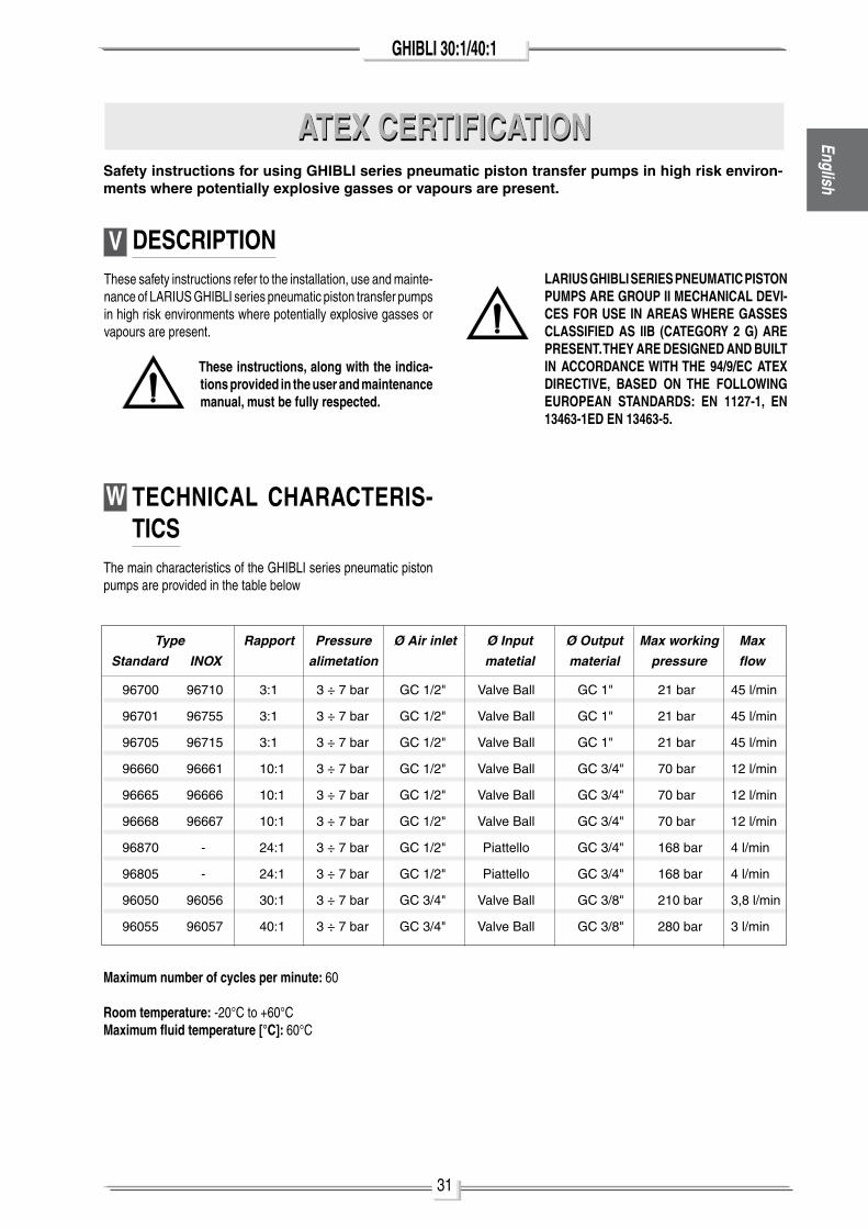
TECHNICAL CHARACTERIS-TICS
The main characteristics of the GhIBlI series pneumatic piston pumps are provided in the table below
LARIUS GHIBLI SERIES PNEUMATIC PISTON PUMPS ARE GROUP II MECHANICAL DEVI-CES FOR USE IN AREAS WHERE GASSES CLASSIFIED AS IIB (CATEGORY 2 G) ARE PRESENT. THEY ARE DESIGNED AND BUILT IN ACCORDANCE WITH THE 94/9/EC ATEX DIRECTIVE, BASED ON THE FOLLOWING EUROPEAN STANDARDS: EN 1127-1, EN 13463-1ED EN 13463-5.
Maximum number of cycles per minute: 60
Room temperature: -20°C to +60°CMaximum fluid temperature [°C]: 60°C
ATEX CERTIFICATIONATEX CERTIFICATIONSafety instructions for using GHIBLI series pneumatic piston transfer pumps in high risk environ-ments where potentially explosive gasses or vapours are present.
96700 96710 3:1 3 ÷ 7 bar GC 1/2" Valve Ball GC 1" 21 bar 45 l/min
96701 96755 3:1 3 ÷ 7 bar GC 1/2" Valve Ball GC 1" 21 bar 45 l/min
96705 96715 3:1 3 ÷ 7 bar GC 1/2" Valve Ball GC 1" 21 bar 45 l/min
96660 96661 10:1 3 ÷ 7 bar GC 1/2" Valve Ball GC 3/4" 70 bar 12 l/min
96665 96666 10:1 3 ÷ 7 bar GC 1/2" Valve Ball GC 3/4" 70 bar 12 l/min
96668 96667 10:1 3 ÷ 7 bar GC 1/2" Valve Ball GC 3/4" 70 bar 12 l/min
96870 - 24:1 3 ÷ 7 bar GC 1/2" piattello GC 3/4" 168 bar 4 l/min
96805 - 24:1 3 ÷ 7 bar GC 1/2" piattello GC 3/4" 168 bar 4 l/min
96050 96056 30:1 3 ÷ 7 bar GC 3/4" Valve Ball GC 3/8" 210 bar 3,8 l/min
96055 96057 40:1 3 ÷ 7 bar GC 3/4" Valve Ball GC 3/8" 280 bar 3 l/min
Type Rapport Pressure Ø Air inlet Ø Input Ø Output Max working Max
Standard INOX alimetation matetial material pressure flow
32
GHIBLI 30:1/40:1
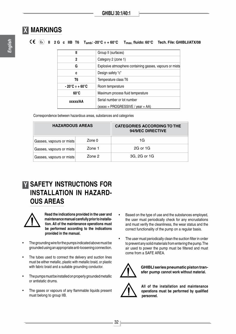
X MARKINGS
3
X II 2 G c IIB T6 Tamb: -20°C ÷ + 60°C Tmax. fluido: 60°C Tech. File: GHIBLI/ATX/08
II
2
G
c
T6
- 20°C ÷ + 60°C
60°C
xxxxx/AA
Group II (surfaces)
Category 2 (zone 1)
Explosive atmosphere containing gasses, vapours or mists
Design safety “c”
Temperature class T6
Room temperature
maximum process fluid temperature
Serial number or lot number
(xxxxx = pRoGRESSIVE / year = aa)
Correspondence between hazardous areas, substances and categories
CATEGORIES ACCORDING TO THE 94/9/EC DIRECTIVE
Gasses, vapours or mists
Gasses, vapours or mists
Gasses, vapours or mists
1G
2G or 1G
3G, 2G or 1G
HAZARDOUS AREAS
Zone 0
Zone 1
Zone 2
Y SAFETY INSTRUCTIONS FOR INSTALLATION IN HAZARD-OUS AREAS
Read the indications provided in the user and maintenance manual carefully prior to installa-tion. All of the maintenance operations must be performed according to the indications provided in the manual.
• The grounding wire for the pumps indicated above must be grounded using an appropriate anti-loosening connection.
• The tubes used to connect the delivery and suction lines must be either metallic, plastic with metallic braid, or plastic with fabric braid and a suitable grounding conductor.
• The pumps must be installed on properly grounded metallic or antistatic drums.
• The gases or vapours of any flammable liquids present must belong to group IIB.
• Based on the type of use and the substances employed, the user must periodically check for any encrustations and must verify the cleanliness, the wear status and the correct functionality of the pump on a regular basis.
• The user must periodically clean the suction filter in order to prevent any solid materials from entering the pump. The air used to power the pump must be filtered and must come from a SaFE aREa.
GHIBLI series pneumatic piston tran-sfer pump cannot work without material.
All of the installation and maintenance operations must be performed by qualified personnel.
Engl
ish
33
GHIBLI 30:1/40:1English
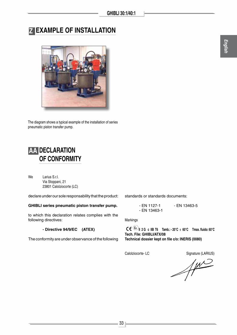
Z EXAMPLE OF INSTALLATION
The diagram shows a typical example of the installation of series pneumatic piston transfer pump.
We larius S.r.l. Via Stoppani, 21 23801 Calolziocorte (lC)
declare under our sole responsability that the product:
GHIBLI series pneumatic piston transfer pump.
to which this declaration relates complies with the following directives:
- Directive 94/9/EC (ATEX)
The conformity are under observance of the following
3
X
standards or standards documents:
- En 1127-1 - En 13463-5 - En 13463-1
markings
II 2 G c IIB T6 Tamb.: - 20°C ÷ 60°C Tmax. fluido: 60°CTech. File: GHIBLI/ATX/08 Technical dossier kept on file c/o: INERIS (0080)
Calolziocorte- lC Signature (laRIuS)
AA DECLARATIONOF CONFORMITY
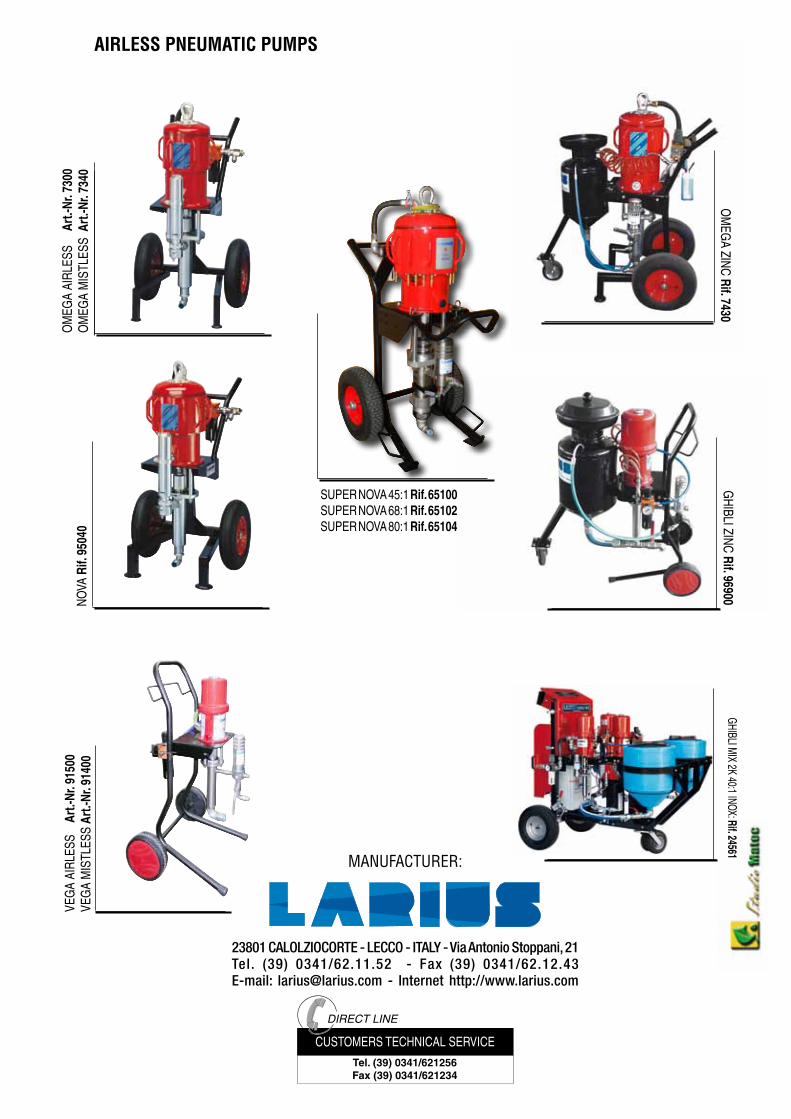
23801 CALOLZIOCORTE - LECCO - ITALY - Via Antonio Stoppani, 21Tel. (39) 0341/62.11.52 - Fax (39) 0341/62.12.43E-mail: [email protected] - Internet http://www.larius.com
AIRLESS PNEUMATIC PUMPS
ManufacTurEr:
DIRECT LINE
Tel. (39) 0341/621256Fax (39) 0341/621234
CuSTomERS TEChnICal SERVICE
noVa
Rif.
950
40G
hIBlI ZInC Rif. 96900o
mEG
a ZInC Rif. 7430o
mEG
a aI
RlES
S
Art.
-Nr.
7300
om
EGa
mIS
TlES
S A
rt.-N
r. 73
40VE
Ga
aIRl
ESS
Ar
t.-Nr
. 915
00VE
Ga
mIS
TlES
S Ar
t.-Nr
. 914
00
SupER noVa 45:1 Rif. 65100SupER noVa 68:1 Rif. 65102SupER noVa 80:1 Rif. 65104
GhIBlI mIX 2K 40:1 InoX: Rif. 24561