OPERATING & MAINTENANCE
31
OPERATING & MAINTENANCE MANUAL ISSUE 8 GROSVENOR PYXEL DIAPHRAGM METERING PUMP 25 th October 1999 Ref No.: om-manua\pump\pyxl.doc Grosvenor Pumps Limited Trevoole, Praze, Camborne, Cornwall. TR14 0PJ England Tel: 01209 831500 Fax: 01209 831939 Email: [email protected]
Transcript of OPERATING & MAINTENANCE
OPERATING &
MAINTENANCE MANUALISSUE 8
GROSVENOR PYXEL DIAPHRAGM METERING PUMP
25th October 1999 Ref No.: om-manua\pump\pyxl.doc
Grosvenor Pumps LimitedTrevoole, Praze,Camborne,Cornwall. TR14 0PJEngland
Tel: 01209 831500Fax: 01209 831939Email: [email protected]
Operating & Maintenance Manual Grosvenor Pumps LtdGrosvenor PYXEL Diaphragm Metering Pump___________________________________________________________________
CONTENTS LIST
SECTION TITLE PAGE1. GENERAL DESCRIPTION 31.1. Grosvenor PYXEL Diaphragm Metering Pump 4
2. TECHNICAL DATA 52.1. Pump 62.2. Motor 62.3 Performance Curves 7
3. PARTS AND DRAWING LIST 83.1. Parts Schedule 103.2. General Assembly - PYXEL Diaphragm Metering Pump 11
GP1731/A1 latest issue3.3. Exploded Assembly - PYXEL Diaphragm Metering Pump 123.4. Installation Detail - PYXEL Diaphragm Metering Pump 13
GP1647/A3 latest issue
4. SAFETY 144.1. Standard Precautions 15
5. INSTALLATION AND COMMISSIONING 175.1. Mounting 185.2. Pipe Connections 185.3. Gearbox Oil 185.4. Electrical 195.5. Commissioning 195.6. General Operation 19
6. MAINTENANCE 216.1. Safety 226.2. General Maintenance 226.3. Motor Removal 226.4. Motor Refitting 226.5. Valve Sub-Assembly Removal 226.6. Valve Sub-Assembly Refitting 236.7. Pump Head Removal 236.8. Pump Head Assembly 236.9. Gearbox Stripping 246.10. Gearbox Reassembly 266.11. Final Assembly 286.12. Spare Parts 286.13. Diaphragm Oil 286.14. Gearbox Lubrication 296.15. Approved Lubricants 29
2
Operating & Maintenance Manual Grosvenor Pumps Ltd.Grosvenor PYXEL Diaphragm Metering Pump___________________________________________________________________
SECTION 1
GENERAL DESCRIPTION
3
Operating & Maintenance Manual Grosvenor Pumps LtdGrosvenor PYXEL Diaphragm Metering Pump___________________________________________________________________
1. GENERAL DESCRIPTION
1.1. Grosvenor PYXEL Diaphragm Metering Pump1.1.1. The PYXEL Diaphragm Metering Pump is a variable output single acting
positive displacement diaphragm pump. The diaphragm is supported by a fully enclosed oil chamber. The volume of oil is displaced by a reciprocating plunger. This deflects the diaphragm by a set amount. The speed and stroke of the plunger equates to the pump delivery. The prime mover is a vertical flange mounted motor driving a worm and wormwheel gear set. This turns an eccentric cam which reciprocates a spring return crosshead and plunger. The flow control is done by a manually variable lost motion micrometer stroke adjuster. Adjustment is from 0 to 100% with through 12.7 turns.
1.1.2. The pumps are manufactured in five standard flow sizes; 3, 5, 10, 25 and 50 l/h. Other sizes can be built to order. The pumps are complete with a standard IP 55 electric motor to give a stroke speed of 60 strokes/minute. Other motor options are available on request for hazardous environments.
1.1.3. High grade engineering materials for wetted parts enable a wide range of aggressive liquids to be handled and the absence of any gland offers zero leakage. The standard construction of the pump head is uPVC with a PTFE diaphragm and glass valve balls suitable with liquids upto 60oC. Other materials are available to special order. The gearbox case is manufactured from cast iron and all internals are in carbon steel.
1.1.4. The standard inlet and outlet port connections is 1/4" BSP. Other port connections, i.e. NPT, flange ports are available on request.
1.1.5. Typical applications are chemical injection, water treatment dosing, sampling or any other application where an economical positive liquid feed is required. The pump can be supplied complete with packaged tank units or in a variety of standard or custom built assemblies.
1.1.6. Various accessories are available including loading valves, relief valves and electrical starters.
4

Operating & Maintenance Manual Grosvenor Pumps LtdGrosvenor PYXEL Diaphragm Metering Pump___________________________________________________________________
SECTION 2
TECHNICAL DATA
5

Operating & Maintenance Manual Grosvenor Pumps LtdGrosvenor PYXEL Diaphragm Metering Pump___________________________________________________________________
2. TECHNICAL DATA
2.1. PumpSizes Plastic 316L stainless
03-10 3 L/Hr 03-70 3 L/Hr05-10 5 L/Hr 05-70 5 L/Hr 10-10 10 L/Hr 10-70 10 L/Hr 25-10 25 L/Hr 25-70 25 L/Hr 50-10 50 L/Hr 50-30 50 L/Hr
PressurePlastic All sizes 10 Bar316L stainless steel All sizes 70 Bar
50-30 30 BarMaterialPump body Standard uPVC
Optional 316L stainless steel25% glass filled PTFEPolypropylene
Diaphragm PTFEValve balls
Standard GlassOptional PTFE
316L stainless steelCeramic
Port Size 1/4" BSPSuction Condition Flooded
Maximum -ve NPSH -1 mViscosity
</= 85 cSt Volumetric efficiency = 100%</= 140 cSt Volumetric efficiency = 90%</= 200 cSt Volumetric efficiency = 80%
2.2. Motor - StandardType IP 55 4 polePower
10 Bar 0.18 kW70/30 Bar 0.37 kW
Speed 1500 rev/minSupply
Standard 415 VAC/3 ph/50 Hz (star)240 VAC/3 ph/50 Hz (delta)
Optional 240 VAC/1 ph/50 HzOperation Continuous
2.3. Weight 20 kg6
Operating & Maintenance Manual Grosvenor Pumps Ltd.Grosvenor PYXEL Diaphragm Metering Pump___________________________________________________________________
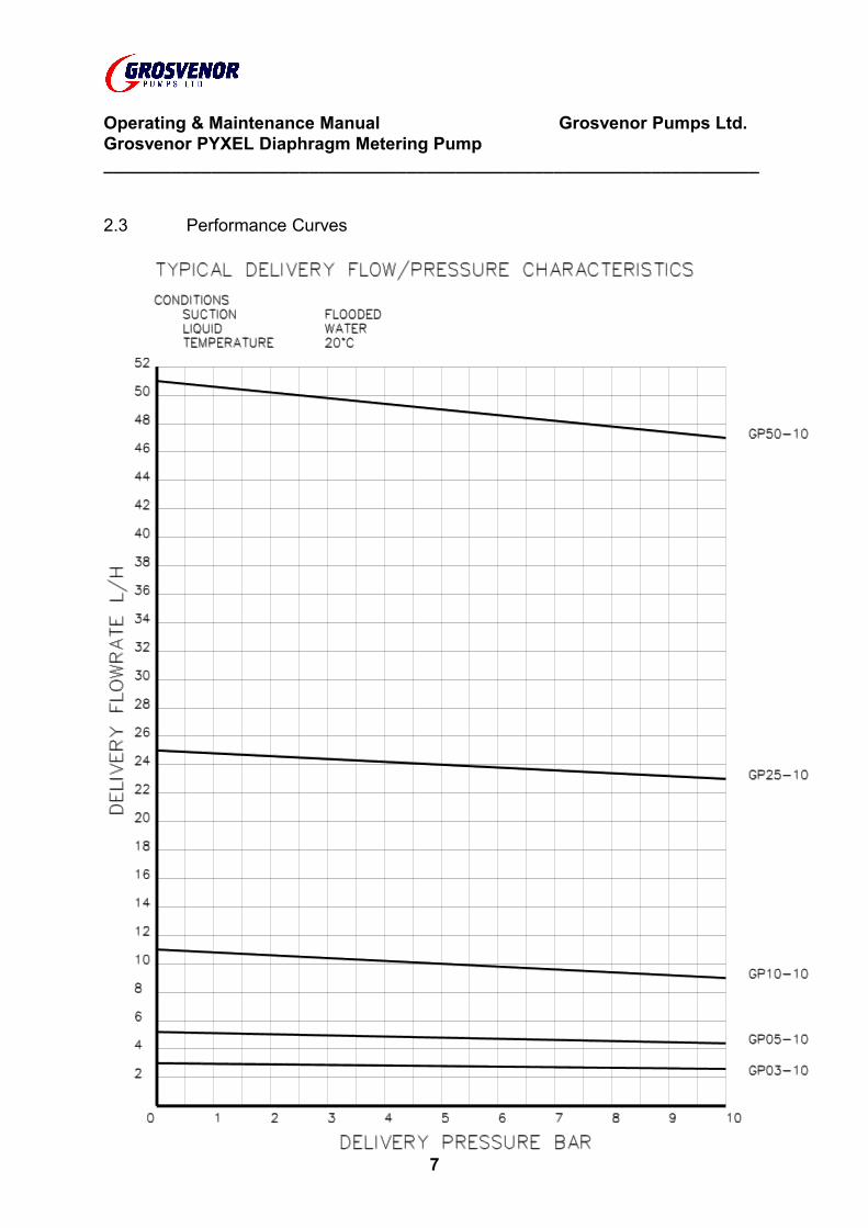
2.3 Performance Curves
7

Operating & Maintenance Manual Grosvenor Pumps Ltd.Grosvenor PYXEL Diaphragm Metering Pump___________________________________________________________________
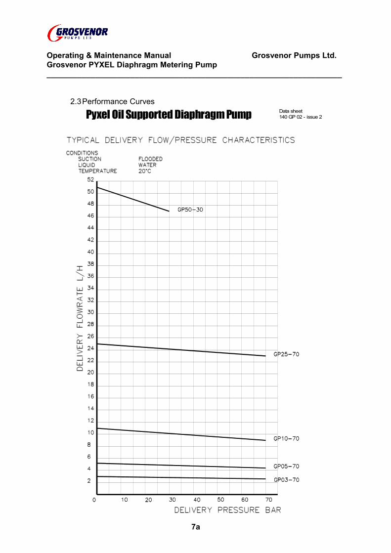
2.3Performance Curves
Pyxel Oil Supported Diaphragm Pump Data sheet 140 GP 02 - issue 2
7a

Operating & Maintenance Manual Grosvenor Pumps Ltd.Grosvenor PYXEL Diaphragm Metering Pump___________________________________________________________________
SECTION 3
PARTS AND DRAWING LIST
8

Operating & Maintenance Manual Grosvenor Pumps Ltd.Grosvenor PYXEL Diaphragm Metering Pump___________________________________________________________________
3. PARTS AND DRAWING LIST3.1. Parts Schedule3.2. General Assembly - PYXEL Diaphragm Metering Pump
GP1731/A1 latest issue3.3. Exploded Assembly - PYXEL Diaphragm Metering Pump3.4. Installation Detail - PYXEL Diaphragm Metering Pump
GP1647/A3 latest issue
9
Operating & Maintenance Manual Grosvenor Pumps Ltd.Grosvenor PYXEL Diaphragm Metering Pump___________________________________________________________________
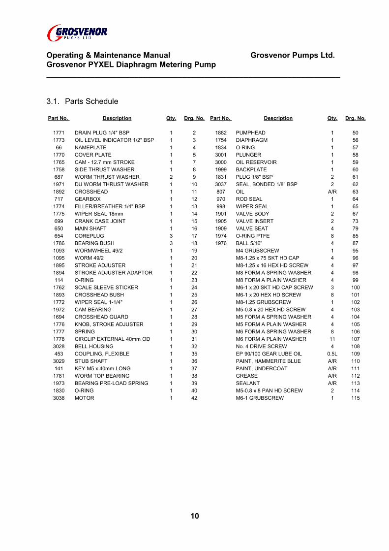
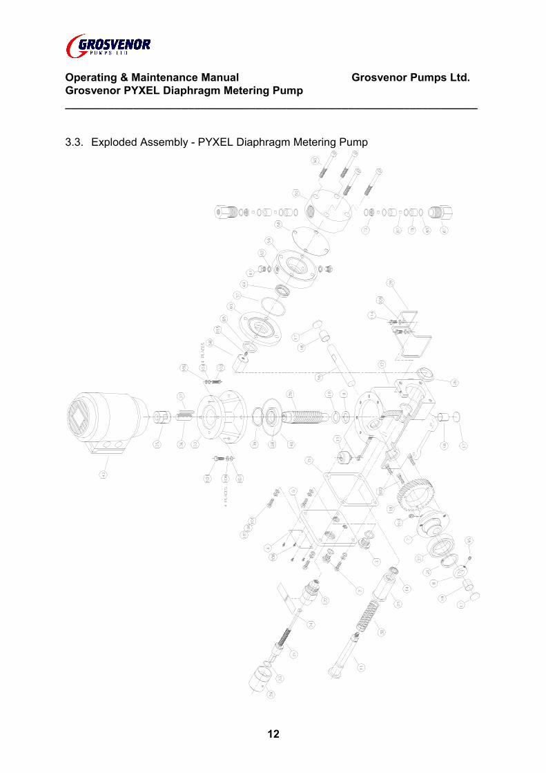
3.1. Parts Schedule
Part No. Description Qty. Drg. No. Part No. Description Qty. Drg. No.
1771 DRAIN PLUG 1/4" BSP 1 2 1882 PUMPHEAD 1 501773 OIL LEVEL INDICATOR 1/2" BSP 1 3 1754 DIAPHRAGM 1 5666 NAMEPLATE 1 4 1834 O-RING 1 57
1770 COVER PLATE 1 5 3001 PLUNGER 1 581765 CAM - 12.7 mm STROKE 1 7 3000 OIL RESERVOIR 1 591758 SIDE THRUST WASHER 1 8 1999 BACKPLATE 1 60687 WORM THRUST WASHER 2 9 1831 PLUG 1/8" BSP 2 611971 DU WORM THRUST WASHER 1 10 3037 SEAL, BONDED 1/8" BSP 2 621892 CROSSHEAD 1 11 807 OIL A/R 63717 GEARBOX 1 12 970 ROD SEAL 1 641774 FILLER/BREATHER 1/4" BSP 1 13 998 WIPER SEAL 1 651775 WIPER SEAL 18mm 1 14 1901 VALVE BODY 2 67699 CRANK CASE JOINT 1 15 1905 VALVE INSERT 2 73650 MAIN SHAFT 1 16 1909 VALVE SEAT 4 79654 COREPLUG 3 17 1974 O-RING PTFE 8 851786 BEARING BUSH 3 18 1976 BALL 5/16" 4 871093 WORMWHEEL 49/2 1 19 M4 GRUBSCREW 1 951095 WORM 49/2 1 20 M8-1.25 x 75 SKT HD CAP
SCREW4 96
1895 STROKE ADJUSTER 1 21 M8-1.25 x 16 HEX HD SCREW 4 971894 STROKE ADJUSTER ADAPTOR 1 22 M8 FORM A SPRING WASHER 4 98114 O-RING 1 23 M8 FORM A PLAIN WASHER 4 991762 SCALE SLEEVE STICKER 1 24 M6-1 x 20 SKT HD CAP SCREW 3 1001893 CROSSHEAD BUSH 1 25 M6-1 x 20 HEX HD SCREW 8 1011772 WIPER SEAL 1-1/4" 1 26 M8-1.25 GRUBSCREW 1 1021972 CAM BEARING 1 27 M5-0.8 x 20 HEX HD SCREW 4 1031694 CROSSHEAD GUARD 1 28 M5 FORM A SPRING WASHER 4 1041776 KNOB, STROKE ADJUSTER 1 29 M5 FORM A PLAIN WASHER 4 1051777 SPRING 1 30 M6 FORM A SPRING WASHER 8 1061778 CIRCLIP EXTERNAL 40mm OD 1 31 M6 FORM A PLAIN WASHER 11 1073028 BELL HOUSING 1 32 No. 4 DRIVE SCREW 4 108453 COUPLING, FLEXIBLE 1 35 EP 90/100 GEAR LUBE OIL 0.5L 1093029 STUB SHAFT 1 36 PAINT, HAMMERITE BLUE A/R 110141 KEY M5 x 40mm LONG 1 37 PAINT, UNDERCOAT A/R 1111781 WORM TOP BEARING 1 38 GREASE A/R 1121973 BEARING PRE-LOAD SPRING 1 39 SEALANT A/R 1131830 O-RING 1 40 M5-0.8 x 8 PAN HD SCREW 2 1143038 MOTOR 1 42 M6-1 GRUBSCREW 1 115
10
Operating & Maintenance Manual Grosvenor Pumps Ltd.Grosvenor PYXEL Diaphragm Metering Pump___________________________________________________________________
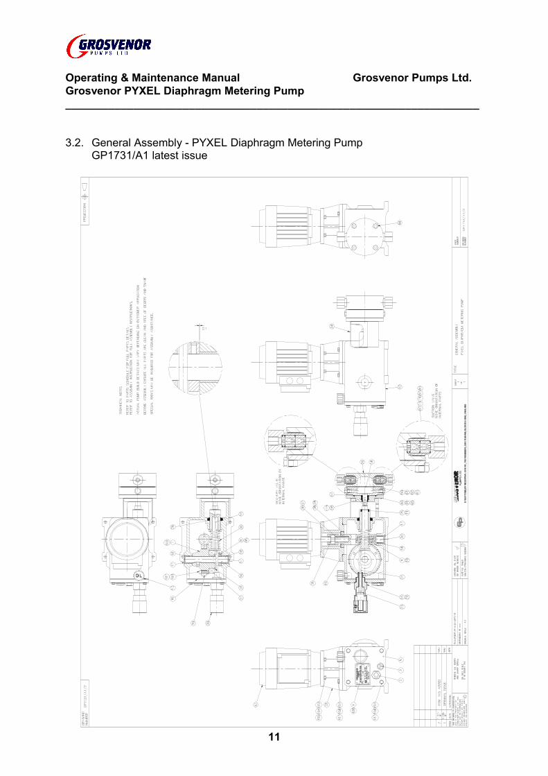
3.2. General Assembly - PYXEL Diaphragm Metering PumpGP1731/A1 latest issue
11
Operating & Maintenance Manual Grosvenor Pumps Ltd.Grosvenor PYXEL Diaphragm Metering Pump___________________________________________________________________
3.3. Exploded Assembly - PYXEL Diaphragm Metering Pump
12
Operating & Maintenance Manual Grosvenor Pumps Ltd.Grosvenor PYXEL Diaphragm Metering Pump___________________________________________________________________
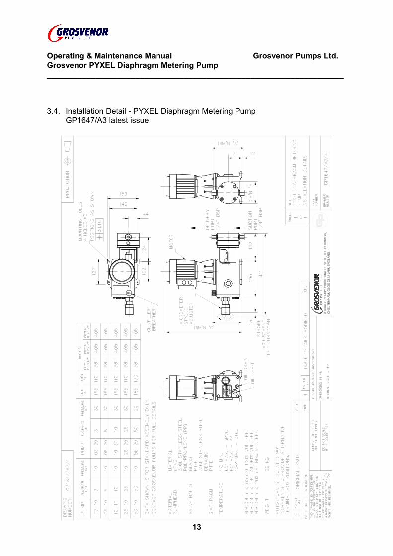
3.4. Installation Detail - PYXEL Diaphragm Metering PumpGP1647/A3 latest issue
13

Operating & Maintenance Manual Grosvenor Pumps Ltd.Grosvenor PYXEL Diaphragm Metering Pump___________________________________________________________________
SECTION 4
SAFETY
14
Operating & Maintenance Manual Grosvenor Pumps Ltd.Grosvenor PYXEL Diaphragm Metering Pump___________________________________________________________________
4. SAFETY
4.1. Standard Precautions4.1.1. To comply with normal safety-standards the following measures are to be
taken:4.1.2. A minimum issue of standard protective clothing to be available to all
personnel involved in the handling of chemicals and operation of the dosing plant, consisting of:
4.1.3. Goggles - with wide-angle vision, contact the skin in complete seal around both eyes and adequately vented without allowing access to spillage.
4.1.4. Safety Helmet - of metal or reinforced plastic to the relevant British Standard or equivalent.
4.1.5. Gloves - wrist length, of soft PVC or rubber permitting full flexure.4.1.6. Overalls - to be worn in conjunction with the items above or a one-piece
chemical suit.4.1.7. Standard site safety provisions, safety precautions and first aid
instructions, in condensed form shall be promulgated at site and in site vehicles. All employees shall be in possession of literature giving full details of safety precautions and first aid action.
4.1.8. The following personal precautions are to be taken when handling chemicals:
4.1.9. Wear standard protective clothing and equipment as detailed above.4.1.10. Ensure that the nature and properties of the chemical being handled are
known in advance.4.1.11. Ensure that the correct precautions for the chemical being handled are
observed. IF IN DOUBT ASK.4.1.12. Treat all materials as harmful.4.1.13. Do not touch chemicals or residues with bare hands.4.1.14. Wash away accidental contact immediately.4.1.15. Keep self and clothes clean.4.1.16. Wash contaminated clothing before re-use.4.1.17. Wash thoroughly after handling chemicals. Do not eat drink or smoke
unless decontaminated.4.1.18. Erect WARNING barriers where necessary.4.1.19. Follow specific process instruction carefully.4.1.20. Mix chemicals in the order specified.4.1.21. CAUTION: CHEMICALS CAN BE HARMFUL. PLEASE OBSERVE
MANUFACTURER'S HANDLING AND STORAGE GUIDELINES.4.1.22. Health Hazards - Harmful in contact with the skin and irritating to the eyes.4.1.23. Handling - Avoid contact with the skin and eyes. Wear suitable protective
clothing gloves and eye protection. Wash out empty container thoroughly with water and add solution to system being treated.
4.1.24. Storage - Keep container in a cool, well ventilated place. Keep away from source of ignition. NO SMOKING.
15
Operating & Maintenance Manual Grosvenor Pumps LtdGrosvenor PYXEL Diaphragm Metering Pump___________________________________________________________________
4.1.25. Spillage and Disposal - Shut off all sources of ignition. Absorb spillage in earth and sand, collect up and remove all contaminated clothing. Eye exposure; in case of contact with eyes, rinse immediately with copious quantities of water. Ingestion; remove patient to fresh air, rest and warm. Administer oxygen or artificial respiration as necessary.
IN ALL CASES SEEK MEDICAL ADVICE AS SOON AS POSSIBLE.
16

Operating & Maintenance Manual Grosvenor Pumps LtdGrosvenor PYXEL Diaphragm Metering Pump___________________________________________________________________
SECTION 5
INSTALLATION AND COMMISSIONING
17
Operating & Maintenance Manual Grosvenor Pumps LtdGrosvenor PYXEL Diaphragm Metering Pump___________________________________________________________________
5. INSTALLATION AND COMMISSIONING
5.1. Mounting5.1.1. For maximum operating life, the pump should be located in a clean cool
dry environment. If the site is classified as a hazardous area ensure the pump meets the site requirements. Position the pump on a rigid base preferably as low as possible relative to the supply for the optimum suction condition. Fix the pump gearbox firmly to the base using four M8-1.25 screws or suitable floor bolts.
5.1.2. If the pump is to be installed in an aggressive, hot, dirty environment, it is advisable to provide some cover. However it is essential to leave adequate ventilation for motor cooling. Do not obstruct the motor fan cover.
5.2. Pipe Connections5.2.1. The suction pipe sizes should be larger than the port connection. The
number of pipe bends should be kept to a minimum to reduce flow losses, pulsation and water hammer effects. Increase the pipe size if long pipe runs are unavoidable. If water hammer is present, fit a pulsation damper unit in the delivery pipe line as close to the pump as possible. For technical advice, please refer to Grosvenor Pumps.
5.2.2. The pump is designed to be self-priming. However, if difficulties are experienced with priming, loosen/remove the delivery valve sub-assembly, fill the pumping chamber with the pumped liquid and refit the valve. Appropriate care should be taken if the liquid is harmful.
5.2.3. Allow sufficient time to fill large diameter and/or long pipe lengths to build up hydraulic pressure. If the pressure does not increase, check:-
All joints are tight and fully sealed and any dump/flushing valves are shut.The relief valve is adjusted to the correct pressure.The suction and delivery lines are connected to the correct pump ports.The liquid is free of large debris and contaminants. Large solids will reduce
valve efficiency. Fit a suction strainer/filter.Entrapped air pockets. Bleed the system.
5.2.4. If there is a high suction head present, a loading valve may be required to prevent syphoning.
5.3. Gearbox Oil5.3.1. Note the pump gearbox is supplied without lubrication oil. Unscrew the
orange filler breather unit and fill the gearbox with a sufficient quantity of suitable oil (refer to Section 5 - Maintenance for approved lubricants). The level should be half way up the oil level indicator glass.
18
Operating & Maintenance Manual Grosvenor Pumps Ltd.Grosvenor PYXEL Diaphragm Metering Pump___________________________________________________________________
5.4. Electrical5.4.1. Before beginning any electrical work, isolate the supply at the mains.5.4.2. Open up the motor terminal box. Connect up a suitably rated power
supply to the motor. Use suitable power multi-core power cable with a cable gland nut. Fasten the power leads firmly to the terminal points. Always connect the supply earth lead.
5.4.3. Three phase motors can be controlled by a direct on-line starter or a frequency inverter. The standard motors can be wired in star or delta with a corresponding voltage variation e.g. either 415 VAC or 240 VAC. Therefore check the power supply.
5.4.4. The motor rotation should be anti-clockwise when viewed from the fan side. For three phase supply, if the rotation is clockwise, change any two of the three supply phases over. The direction for single phase motors has been factory set to be anti-clockwise. However, if the rotation is clockwise interchange the blue and yellow leads on terminals 2 and 3.
5.4.5. As the pump will operate upto the motor stalling point, it is recommended that an electrical overload trip device is fitted and/or a hydraulic relief valve fitted in the delivery line. To allow for start-up current surge, current trips should be 6 to 7 times the full load motor current. If the supply is from a frequency inverter, the motor should be specified with a thermistor which is compatible with the frequency inverter. Unless a blower is fitted to the motor, turndown must be limited to 3:1 with an inverter.
5.5. Commissioning5.5.1. After pipe and electrical installation has been completed run the pump
between 30 and 60 minutes at minimum hydraulic load and full flow. Examine the entire hydraulic system including the pump for any leakages. Check the pump for unusual noises and vibration. For the first 14 days operation, expect the pump gearbox to run at a temperature of 65-70oC. This will in no way affect the overall pump performance.
5.6. General Operation5.6.1. The flow can be varied 0-100% by turning the micrometer stroke adjuster.
The one turn corresponds to 1mm stroke. The total stroke length is 12.7mm (1/2"). The graduated scale provides a visual indication. For accurate calibration, wind in the stroke adjuster until there is no plunger movement. This can be observed at the pumphead end through the transparent guard. Unwind the adjuster 12.7 mm (12.7 turns). Measure the flow. This can be done with a measuring beaker and a stopwatch. Divide the flow by 12.7 to give the flow per turn. The maximum flow figure will vary with pressure. Generally delivery flow decreases as delivery pressure increases.
5.6.2. Do not unwind the micrometer adjuster more than 13 turns from the zero position.
19
Operating & Maintenance Manual Grosvenor Pumps LtdGrosvenor PYXEL Diaphragm Metering Pump___________________________________________________________________
5.6.3. Only ever turn the micrometer adjuster by hand. Do not use tools suchas pliers or molegrips.
5.6.4. Check the system for water and chemical leaks, if the latter, follow the procedures detailed in sections 4.1.1.
5.6.5. Check the pump for excessive vibration, noise and overheating.5.6.6. Ensure that any associated instruments in the system are functioning
correctly and that their displays are meaningful.5.6.7. Operate the pump within the specified duty. Please note that the
performance data specified in section 2.1. is the recommended maximums for each pump. To avoid damaging the pump, do not exceed the operating conditions as stated in the Section 2 Technical Data.
5.6.8. Check the pump will operate satisfactorily if it is to be used for another duty, i.e. different liquid, pressure, environment, power supply.
5.6.9. Always handle the pump by gripping the gearbox case and not by the pump head, valves or any pipework attached to the pump head.
20
Operating & Maintenance Manual Grosvenor Pumps Ltd.Grosvenor PYXEL Diaphragm Metering Pump___________________________________________________________________
SECTION 6
MAINTENANCE
21
Operating & Maintenance Manual Grosvenor Pumps Ltd.Grosvenor PYXEL Diaphragm Metering Pump___________________________________________________________________
6. MAINTENANCE
6.1. SafetyCAUTION: BEFORE STARTING ANY MAINTENANCE PROCEDURE,
ENSURE THAT ALL SAFETY INSTRUCTIONS DETAILED IN THE CURRENT WORKS MANUAL HAVE BEEN COMPLIED WITH.
6.2. General Maintenance6.2.1. General maintenance is an oil change every 6 months. If the pump is in
continuous operation at maximum duty, a detailed inspection of parts will be required at 12 month intervals. The pump unit is easily dismantled but special tools will be required. Full spares and special tools are available from Grosvenor Pumps.
6.3. Motor Removal6.3.1. Isolate the electric power supply at the mains. Disconnect wires from the
Motor terminal box. The Motor lifts off the drive unit after removing the four screws on the motor flange part of the Bell-housing. The top section of the flexible coupling will come away with the motor shaft. The Motor is non-serviceable. Examine for wear and/or damage. Replace if necessary.
6.4. Motor Refitting6.4.1. Replace the top section of the flexible coupling. Reposition the Motor onto
the bell housing location spigot. Ensure the flexible coupling sections interlock. Tighten the four flange screws.
6.4.2. Connect wiring to ensure rotation is anti-clockwise when viewing Motor on fan end. Refer to Section 5.4 Electrical of Installation and Commissioning.
6.5. Valve Sub-Assembly Removal6.5.1. To remove the suction and delivery Valve Sub-Assemblies, first
disconnect suction and delivery piping from the Valve Body connection.6.5.2. Unscrew the suction and the delivery Valve Sub-Assemblies from the
Pump Head. Tip out the two Valve Seats (1909), one Valve Insert (1905), two Balls (1976) and four O-Rings (1974) from the Valve Body (1901). Note the different orientation of the parts for the suction and the delivery valves. Examine valve components for wear and damage. Discard and replace as necessary. Always rebuild with new seals. The components for the Suction and Delivery Valve Sub-Assemblies are identical, but are different in orientation.
22
Operating & Maintenance Manual Grosvenor Pumps Ltd.Grosvenor PYXEL Diaphragm Metering Pump___________________________________________________________________
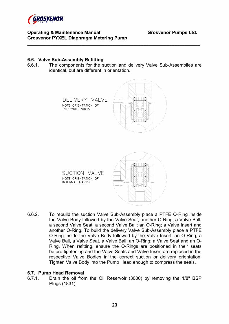
6.6. Valve Sub-Assembly Refitting6.6.1. The components for the suction and delivery Valve Sub-Assemblies are
identical, but are different in orientation.
6.6.2. To rebuild the suction Valve Sub-Assembly place a PTFE O-Ring inside the Valve Body followed by the Valve Seat, another O-Ring, a Valve Ball, a second Valve Seat, a second Valve Ball; an O-Ring; a Valve Insert and another O-Ring. To build the delivery Valve Sub-Assembly place a PTFE O-Ring inside the Valve Body followed by the Valve Insert, an O-Ring, a Valve Ball, a Valve Seat, a Valve Ball; an O-Ring; a Valve Seat and an O-Ring. When refitting, ensure the O-Rings are positioned in their seats before tightening and the Valve Seats and Valve Insert are replaced in the respective Valve Bodies in the correct suction or delivery orientation. Tighten Valve Body into the Pump Head enough to compress the seals.
6.7. Pump Head Removal6.7.1. Drain the oil from the Oil Reservoir (3000) by removing the 1/8" BSP
Plugs (1831).
23
Operating & Maintenance Manual Grosvenor Pumps Ltd.Grosvenor PYXEL Diaphragm Metering Pump___________________________________________________________________
6.7.2. Remove the four capscrews securing the Pump Head Assembly to the Gearbox Assembly. The Pump Head (1882), Diaphragm (1754), Oil Reservoir and Backplate (1999) can be removed. Hold the Crosshead with a 15 mm A/F spanner. Unscrew the Plunger (3001) from the Crosshead with a 3 mm A/F allen key. Do not mark the Plunger or the Crosshead sealing faces by using mole grips.
6.7.3. The Rod Seal (970) and the Wiper Seal (998) can be extracted from the Backplate. Always rebuild with new seals.
6.7.4. Always discard and replace the Diaphragm.
6.8. Pumphead Assembly6.8.1. Discard and replace the Plunger if the surface is anything but smooth and
mirror finish (Ra 0.4 microns maximum).6.8.2. Screw the Plunger onto the Crosshead with a 3 mm A/F allen key. Hold
the Crosshead with a 15 mm A/F spanner and turn the allen key to screw in the Plunger. Do not mark the Plunger or the Crosshead sealing faces by using mole grips.
6.8.3. Fit the Wiper Seal and Rod Seal into the Backplate. Smear clean oil onto the Plunger, Wiper and Rod Seal. Slide the Backplate onto the Plunger to locate onto the Gearbox Pumphead mounting flange. Turn the backplate to align the mounting holes. Fit the Oil Reservoir, Diaphragm and Pumphead fastened with four M8-1.25 x 75 Capscrews. Fit the bottom Plug with Bonded Seal onto the Oil Reservoir.
6.8.4. Turn the worm to wind back the Crosshead to its Bottom Dead Centre (BTDC) position. Through the top hole fill the Oil Reservoir with Oil pouring it in slowly to avoid air pockets. Leave to stand for a three minutes to allow any suspended air to rise out. Top up as necessary. Fit the top Plug and Bonded Seal.
6.8.5. The diaphragm must be stretched into shape before full recommissioning. The amount it stretches is the volume of oil displaced by the plunger. Turning the worm will reciprocate the plunger and stretch the diaphragm. Check for leaks and smoothness of operation.
6.9. Gearbox Stripping6.9.1. Special tools required will be required stripping the gearbox:-
Crosshead Spring Compressor - Grosvenor Part No. 1840Bush liner mandrel - Grosvenor Part No. 1841Crosshead bush mandrel - Grosvenor Part No. 1842
6.9.2. Remove the Motor and Pump End assembly. It is impractical to strip the Gearbox Assembly with the Pump still mounted in its installed environment.
6.9.3. Drain the gearbox oil by undoing the drain Plug (1771). Discard the oil.
24
Operating & Maintenance Manual Grosvenor Pumps Ltd.Grosvenor PYXEL Diaphragm Metering Pump___________________________________________________________________
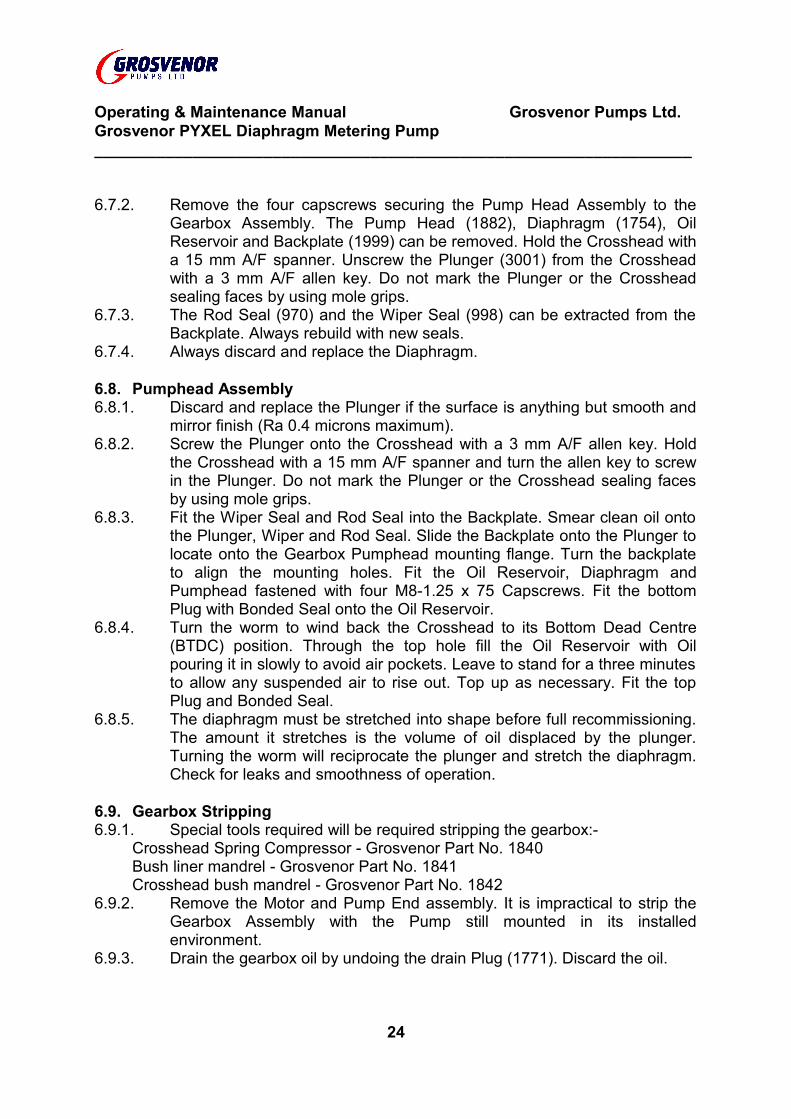
6.9.4. Access to the internal parts is after removing Crankcase Cover Plate (1770). Undo the four screws holding the Bell Housing (3028) to the Gearbox (717). Tip out the Bearing (1781) and the Pre-Load Spring (1973). Lift out the Flexible Coupling (453), the Worm (1095) with the Stub Shaft (3029), the plain Worm Thrust Washer (687) and the DU Worm Thrust Washer (1971). Place the Crosshead Spring Compressor onto the Pumphead mounting flange on the Gearbox.
Wind in the M16-2.0 compressor screw to fully fasten onto the M8-1.25 threaded section of the Crosshead. Without unscrewing the Crosshead unwind the compressor screw to pull in the Crosshead. To remove the internals first loosen the lock grubscrew in the Cam (1765) and the lock screw in the Side Thrust Washer (1758). With a centre punch, hammer out the Core Plugs (654) from either side. Ease out the Main Shaft (650). The Cam Sub-Assembly and the Side Thrust Washer will drop out. Carefully unwind the Crosshead Spring Compressor to take the load off the spring. Unscrew the compressor screw from the Crosshead. Extract the Crosshead and the Spring. Examine the crosshead bearing surface. Repolish to a mirror finish (Ra 0.4 microns maximum) or discard and replace if badly scored.
6.9.5 Examine the two Main Shaft, the Worm journal DU Liner and Crosshead Bushes for wear and/or damage. If required press them out with their respective mandrels and replace.
25
Operating & Maintenance Manual Grosvenor Pumps Ltd.Grosvenor PYXEL Diaphragm Metering Pump___________________________________________________________________
6.9.6 Remove the Circlip (1778) holding the Bearing (1972) to the Cam. Lift off the Bearing. Examine for wear and/or damage. Replace is necessary.
Unscrew the three capscrews holding the Wormwheel (1093) to the Cam. Lift off the Wormwheel. Examine for wear and/or damage. Replace is necessary.
Unscrew the Stroke Adjuster (1895) from the Stroke Adjuster Adaptor (1894). Discard and replace the O-Ring (114).
6.10. Gearbox Reassembly6.10.1. Special tools required will be required assembling the gearbox:-
Crosshead Spring Compressor - Grosvenor Part No. 1840Bush liner mandrel - Grosvenor Part No. 1841Crosshead bush mandrel - Grosvenor Part No. 1842
6.10.2. Clean all loose debris from all parts. Pay extra attention to the Gearbox (Item 12) internals.
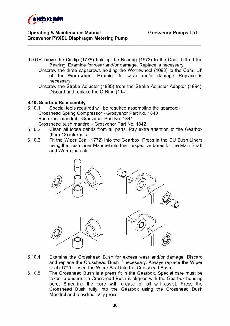
6.10.3. Fit the Wiper Seal (1772) into the Gearbox. Press in the DU Bush Liners using the Bush Liner Mandrel into their respective bores for the Main Shaft and Worm journals.
6.10.4. Examine the Crosshead Bush for excess wear and/or damage. Discard and replace the Crosshead Bush if necessary. Always replace the Wiper seal (1775). Insert the Wiper Seal into the Crosshead Bush.
6.10.5. The Crosshead Bush is a press fit in the Gearbox. Special care must be taken to ensure the Crosshead Bush is aligned with the Gearbox housing bore. Smearing the bore with grease or oil will assist. Press the Crosshead Bush fully into the Gearbox using the Crosshead Bush Mandrel and a hydraulic/fly press.
26
Operating & Maintenance Manual Grosvenor Pumps Ltd.Grosvenor PYXEL Diaphragm Metering Pump___________________________________________________________________
6.10.6. Fit the Worm Wheel onto the Cam with the three M6-1.0 Capscrews. Before fully tightening the Capscrews, check that they do not protrude beyond the surface on the otherside of the cam. If they do, they will foul with the Cam Bearing. File/grind/machine or fit M6 Plain Washers to suit.
6.10.7. Fit the Cam Bearing onto the Cam and hold inplace with the Circlip. Screw in the M8-1.25 Grubscrew into the Cam by a few threads.
6.10.8. Slide the Spring onto the Crosshead. Insert the Crosshead into the Crosshead Bush. The Spring must be compressed to allow the other internal parts to be fitted. Place the crosshead spring compressor on to the Pumphead mounting flange on the Gearbox. Wind in the M16-2.0 compressor screw to fully fasten onto the M8-1.25 threaded section of the Crosshead. Without unscrewing the Crosshead wind the compressor screw to pull in the Crosshead allowing sufficient room for the internal parts. Take care that the Crosshead does not damage the Wiper Seal as it is pulled into the Crosshead Bush. If it appears to snag on the Wiper Seal lip, using a blunt instrument ease the lip back over the Crosshead.
6.10.9. Place the Cam sub-assembly inside the Gearbox. Align the Main Shaft (Item 16) with the machined flat section facing the M6-1.0 Grubscrew in the Cam and slide it through the DU Liner Bush, Cam, Side Thrust Washer (Item 8) and the second Du Bush Liner.
6.10.10. Turn the Gearbox onto its side. Squirt some oil onto the DU Bush Liner. Coat waterproof sealant (Hermetite/liquid gasket) around the edge of a Core Plug (Item 17) and place it onto the DU Bush Liner counterbore. Hammer the Core Plug firmly into place. Repeat for the other DU Bush Liners.
6.10.11. Slide the Cam against the the Gearbox side and tighten the M6-1.0 Grubscrew in the Cam to lock it onto the Main Shaft. Place a feeler gauge set to 0.1 mm (4 thou) between the Slide the Side Thust Washer and Gearbox. Press the Side Thrust Washer against the Gearbox and screw in the M4-0.7 Grubscrew to lock the Side Thrust washer onto the Main Shaft.
6.10.12. Carefully unscrew the Spring compressor to release the spring tension and lower the Crosshead onto the Cam Bearing.
6.10.13. Fit the Stroke Adaptor with thread sealant around the 3/4" BSP threaded section into the Cover Plate. Slip the O-Ring onto the Stroke Adjuster seal groove. Apply oil around the Stroke Adjuster and O-Ring and screw it into the Stroke Adjuster Adaptor. Place a Gearbox Gasket onto the Gearbox end. Fit the Cover Plate onto the Gearbox end without disturbing the Gasket. It may be necessary to unwind the Stroke Adjuster to allow to allow the Cover Plate to sit flush against Gearbox. Fasten the Cover Plate with four M6-1.0 x 20 Hexagonal Head Screws, four M6 Spring Washers and four M6 Plain Washers.
6.10.14. Fit the Drain Plug, Oil Level Indicator and Filler Breather.6.10.15. Fit the Worm with a Worm Thrust Washer and DU Worm Thrust Washer
into the Gearbox.27
Operating & Maintenance Manual Grosvenor Pumps Ltd.Grosvenor PYXEL Diaphragm Metering Pump___________________________________________________________________
6.10.16. Pour in enough oil upto the Oil Level Indicator. Turn the Worm with the worm crank handle. Check for smoothness of operation.
6.10.17. Fit the Stub Shaft, Key, Flexible Coupling and the Worm Top Bearing onto the Worm. Fit the Bearing Pre-Load Spring and the O-Ring into the Bell Housing. Fit the Bell Housing onto the Gearbox and fasten with four M6-1.0 x 20 Hexagonal Head Screws, four M6 Spring Washers and four M6 Plain Washers.
6.11. Final Assembly6.11.1. Fit the Motor with four M5-0.8 x 20 Screws, four M5 Spring Washers and
four M5 Plain Washers.6.11.2. Set the Crosshead to its Bottom Dead Centre (BTDC) position. Apply the
Scale Sleeve Sticker (Item 24) onto the Stroke Adjuster Adaptor such that the graduations on the Knob (Item 29) are aligned with the marks on the sticker.
6.11.3. Fit Nameplate (Item 4) and Crosshead Guard6.11.4. Connect wiring to give correct rotation, 6.4.2. (b).6.11.5. Replace pumphead and valve assemblies as in 6.6 and 6.8..6.11.6. Run-in for 2 hours. Drain the gearbox and refill with fresh oil.
6.12. Spare Parts (Refer to Section 6.1. Key to Diagram of Parts)6.12.1. Spare parts and special tools are available from Grosvenor Pumps. Parts
can be identified on the drawing by part number. ALWAYS QUOTE THE SERIAL NUMBER which can be found on pump crankcase cover. Parts and special tools should be ordered from:-
Grosvenor Pumps LimitedTrevoole, Praze,
Camborne,Cornwall. TR14 0PJTel. 01209 831500Fax. 01209 831939
6.13. Diaphragm Oil6.13.1. The Diaphragm is supported by an oil filled reservoir. Pumps are filled
when supplied but should be checked before commissioning. A refill bottle is supplied with the pump with the correct oil grade.Oil reservoir capacity - Approx. 70 mL
28
Operating & Maintenance Manual Grosvenor Pumps Ltd.Grosvenor PYXEL Diaphragm Metering Pump___________________________________________________________________
6.14. Gearbox Lubrication6.14.1. Pump gearbox is empty when supplied and should be filled before
commissioning. Recommended grades are shown on pump nameplate. Equivalent grades are listed. The oil level is shown on the transparent level plug and should be checked weekly. Change the oil every 6 months. All gearbox parts are lubricated by splash. Motor bearings are fully charged with grease and sealed for life by the manufacturer.Gearbox capacity - Approx. 300 mL
6.15. Approved Lubricants - Gearboxes6.15.1. Oil grades based on ambient temperatures, suitable for normal
applications. The recommendations are based on current information available and responsibility cannot be accepted for quality or suitability of oil supplied nor to any mechanical defect due to unsatisfactory lubrication.
6.15.2. Oils marked * contain mild E.P. additives and should not be used for units operating above 80oC normal running temperatures.
6.15.3. In general these oils should not be used below -4oC. If intended for such use, Grosvenor Pumps can recommend suitable oils for lower temperatures.
6.15.4. Oils marked # are usually obtainable at garages and motor factors.
SUPPLIER OILS
BP Oil Ltd. Energol HLP 320Energol CS 320 *Hypogear 90 EP #
Burmah - Castrol (UK) Ltd. Alpha ZN 320Castrol ST 90 #Hypoy EP 90 #
Esso Petroleum Ltd. Teresso 320GX 85W/90
Gulf Oil (GB) Ltd. Harmony 320Mobil Oil Co. Ltd. DTE AA
HD 140 #GX 140 #
Shell Vitrea 320 *Macoma R 320 *Tellus V320HD 90/140#
Texaco Ltd. Regal R & O 320
29