OpenStack Networking Guide
98
Draft docs.openstack.org
-
Upload
doankhuong -
Category
Documents
-
view
228 -
download
0
Transcript of OpenStack Networking Guide
Dra
ft -
Dra
ft -
Dra
ft -
Dra
ft -
Dra
ft -
Dra
ft -
Dra
ft -
Dra
ft -
Dra
ft -
Dra
ft -
Dra
ft -
Dra
ft -
Dra
ft -
Dra
ft -
Dra
ft -
Dra
ft -
Dra
ft -
Dra
ft -
Dra
ft -
Dra
ft -
Dra
ft -
Dra
ft -
Dra
ft -
Dra
ft -
Dra
ft -
Dra
ft -
Dra
ft -
Dra
ft -
Dra
ft -
Dra
ft -
Dra
ft -
Dra
ft -
Dra
ft -
Dra
ft -
Dra
ft -
Networking Guide March 31, 2015 current
ii
OpenStack Networking Guidecurrent (2015-03-31)Copyright © 2014, 2015 OpenStack Foundation Some rights reserved.
This guide targets OpenStack administrators seeking to deploy and manage OpenStack Networking.
Licensed under the Apache License, Version 2.0 (the "License"); you may not use this file except in compliance with the License. Youmay obtain a copy of the License at
http://www.apache.org/licenses/LICENSE-2.0
Unless required by applicable law or agreed to in writing, software distributed under the License is distributed on an "AS IS" BASIS,WITHOUT WARRANTIES OR CONDITIONS OF ANY KIND, either express or implied. See the License for the specific language governingpermissions and limitations under the License.
Except where otherwise noted, this document is licensed underCreative Commons Attribution ShareAlike 3.0 License.http://creativecommons.org/licenses/by-sa/3.0/legalcode
Dra
ft -
Dra
ft -
Dra
ft -
Dra
ft -
Dra
ft -
Dra
ft -
Dra
ft -
Dra
ft -
Dra
ft -
Dra
ft -
Dra
ft -
Dra
ft -
Dra
ft -
Dra
ft -
Dra
ft -
Dra
ft -
Dra
ft -
Dra
ft -
Dra
ft -
Dra
ft -
Dra
ft -
Dra
ft -
Dra
ft -
Dra
ft -
Dra
ft -
Dra
ft -
Dra
ft -
Dra
ft -
Dra
ft -
Dra
ft -
Dra
ft -
Dra
ft -
Dra
ft -
Dra
ft -
Dra
ft -
Networking Guide March 31, 2015 current
iii
Table of ContentsPreface .......................................................................................................................... vii
Conventions ........................................................................................................... viiDocument change history ...................................................................................... vii
1. Get started with OpenStack ........................................................................................ 1Conceptual architecture .......................................................................................... 2Logical architecture ................................................................................................. 2OpenStack services .................................................................................................. 4Feedback ............................................................................................................... 18
2. Introduction to networking ....................................................................................... 19Networking layers ................................................................................................. 19Switches ................................................................................................................ 20Routers ................................................................................................................. 20Firewalls ................................................................................................................ 20Tunnel (segmentation) technologies ...................................................................... 21Namespaces .......................................................................................................... 21Neutron data model ............................................................................................. 21
3. Networking architecture ............................................................................................ 22Tenant and provider networks .............................................................................. 22VMware NSX integration ...................................................................................... 23Overview ............................................................................................................... 23Server .................................................................................................................... 24Plug-ins .................................................................................................................. 24Agents .................................................................................................................. 24
4. Plugins ...................................................................................................................... 26ML2 ...................................................................................................................... 26Proprietary ............................................................................................................ 27
5. Deployment .............................................................................................................. 28Example architecture ............................................................................................. 29Authentication ...................................................................................................... 29Scenarios ............................................................................................................... 29
6. Scalability and high availability .................................................................................. 52DHCP Agents ......................................................................................................... 52L3 Agents .............................................................................................................. 52Distributed Virtual Router (DVR) ........................................................................... 52
7. Advanced configuration options ................................................................................ 56Advanced agent options ....................................................................................... 56Advanced operational features .............................................................................. 62Advanced features through API extensions ............................................................ 64Firewall-as-a-Service ............................................................................................... 81VPN-as-a-service ..................................................................................................... 81Service chaining ..................................................................................................... 81
8. Troubleshoot OpenStack Networking ........................................................................ 82Visualize OpenStack Networking service traffic in the cloud ................................... 82Troubleshoot network namespace issues ............................................................... 82Troubleshoot Open vSwitch ................................................................................... 83Debug DNS issues .................................................................................................. 84
A. Community support .................................................................................................. 86Documentation ..................................................................................................... 86

Dra
ft -
Dra
ft -
Dra
ft -
Dra
ft -
Dra
ft -
Dra
ft -
Dra
ft -
Dra
ft -
Dra
ft -
Dra
ft -
Dra
ft -
Dra
ft -
Dra
ft -
Dra
ft -
Dra
ft -
Dra
ft -
Dra
ft -
Dra
ft -
Dra
ft -
Dra
ft -
Dra
ft -
Dra
ft -
Dra
ft -
Dra
ft -
Dra
ft -
Dra
ft -
Dra
ft -
Dra
ft -
Dra
ft -
Dra
ft -
Dra
ft -
Dra
ft -
Dra
ft -
Dra
ft -
Dra
ft -
Networking Guide March 31, 2015 current
iv
ask.openstack.org .................................................................................................. 87OpenStack mailing lists .......................................................................................... 87The OpenStack wiki ............................................................................................... 88The Launchpad Bugs area ..................................................................................... 88The OpenStack IRC channel ................................................................................... 89Documentation feedback ...................................................................................... 89OpenStack distribution packages ........................................................................... 89
Glossary ......................................................................................................................... 90

Dra
ft -
Dra
ft -
Dra
ft -
Dra
ft -
Dra
ft -
Dra
ft -
Dra
ft -
Dra
ft -
Dra
ft -
Dra
ft -
Dra
ft -
Dra
ft -
Dra
ft -
Dra
ft -
Dra
ft -
Dra
ft -
Dra
ft -
Dra
ft -
Dra
ft -
Dra
ft -
Dra
ft -
Dra
ft -
Dra
ft -
Dra
ft -
Dra
ft -
Dra
ft -
Dra
ft -
Dra
ft -
Dra
ft -
Dra
ft -
Dra
ft -
Dra
ft -
Dra
ft -
Dra
ft -
Dra
ft -
Networking Guide March 31, 2015 current
v
List of Figures1.1. OpenStack conceptual architecture ........................................................................... 21.2. Logical architecture .................................................................................................. 35.1. Example VXLAN tunnel .......................................................................................... 396.1. DVR configuration diagram .................................................................................... 53
Dra
ft -
Dra
ft -
Dra
ft -
Dra
ft -
Dra
ft -
Dra
ft -
Dra
ft -
Dra
ft -
Dra
ft -
Dra
ft -
Dra
ft -
Dra
ft -
Dra
ft -
Dra
ft -
Dra
ft -
Dra
ft -
Dra
ft -
Dra
ft -
Dra
ft -
Dra
ft -
Dra
ft -
Dra
ft -
Dra
ft -
Dra
ft -
Dra
ft -
Dra
ft -
Dra
ft -
Dra
ft -
Dra
ft -
Dra
ft -
Dra
ft -
Dra
ft -
Dra
ft -
Dra
ft -
Dra
ft -
Networking Guide March 31, 2015 current
vi
List of Tables1.1. OpenStack services ................................................................................................... 11.2. Storage types ........................................................................................................... 83.1. General distinct physical data center networks ........................................................ 227.1. Settings .................................................................................................................. 577.2. Settings .................................................................................................................. 577.3. Settings .................................................................................................................. 587.4. Settings .................................................................................................................. 607.5. Provider extension terminology .............................................................................. 657.6. Provider network attributes .................................................................................... 667.7. Router .................................................................................................................... 687.8. Floating IP .............................................................................................................. 687.9. Basic L3 operations ................................................................................................. 697.10. Security group attributes ...................................................................................... 707.11. Security group rules .............................................................................................. 707.12. Basic security group operations ............................................................................. 717.13. Firewall rules ........................................................................................................ 737.14. Firewall policies .................................................................................................... 747.15. Firewalls ............................................................................................................... 747.16. VMware NSX QoS attributes ................................................................................. 757.17. Basic VMware NSX QoS operations ....................................................................... 767.18. Recommended values for max_lp_per_bridged_ls .................................................. 767.19. Configuration options for tuning operational status synchronization in the NSXplug-in ........................................................................................................................... 777.20. Big Switch Router rule attributes .......................................................................... 787.21. Label .................................................................................................................... 797.22. Rules .................................................................................................................... 797.23. Basic L3 operations ............................................................................................... 81
Dra
ft -
Dra
ft -
Dra
ft -
Dra
ft -
Dra
ft -
Dra
ft -
Dra
ft -
Dra
ft -
Dra
ft -
Dra
ft -
Dra
ft -
Dra
ft -
Dra
ft -
Dra
ft -
Dra
ft -
Dra
ft -
Dra
ft -
Dra
ft -
Dra
ft -
Dra
ft -
Dra
ft -
Dra
ft -
Dra
ft -
Dra
ft -
Dra
ft -
Dra
ft -
Dra
ft -
Dra
ft -
Dra
ft -
Dra
ft -
Dra
ft -
Dra
ft -
Dra
ft -
Dra
ft -
Dra
ft -
Networking Guide March 31, 2015 current
vii
Preface
ConventionsThe OpenStack documentation uses several typesetting conventions.
Notices
Notices take these forms:
Note
A handy tip or reminder.
Important
Something you must be aware of before proceeding.
Warning
Critical information about the risk of data loss or security issues.
Command prompts
$ prompt Any user, including the root user, can run commands that are prefixed withthe $ prompt.
# prompt The root user must run commands that are prefixed with the # prompt. Youcan also prefix these commands with the sudo command, if available, to runthem.
Document change historyThis version of the guide replaces and obsoletes all earlier versions.
The following table describes the most recent changes:
Revision Date Summary of Changes
August 8, 2014 • Creation of document.

Dra
ft -
Dra
ft -
Dra
ft -
Dra
ft -
Dra
ft -
Dra
ft -
Dra
ft -
Dra
ft -
Dra
ft -
Dra
ft -
Dra
ft -
Dra
ft -
Dra
ft -
Dra
ft -
Dra
ft -
Dra
ft -
Dra
ft -
Dra
ft -
Dra
ft -
Dra
ft -
Dra
ft -
Dra
ft -
Dra
ft -
Dra
ft -
Dra
ft -
Dra
ft -
Dra
ft -
Dra
ft -
Dra
ft -
Dra
ft -
Dra
ft -
Dra
ft -
Dra
ft -
Dra
ft -
Dra
ft -
Networking Guide March 31, 2015 current
1
1. Get started with OpenStack
Table of ContentsConceptual architecture .................................................................................................. 2Logical architecture ......................................................................................................... 2OpenStack services .......................................................................................................... 4Feedback ....................................................................................................................... 18
The OpenStack project is an open source cloud computing platform for all types of clouds,which aims to be simple to implement, massively scalable, and feature rich. Developers andcloud computing technologists from around the world create the OpenStack project.
OpenStack provides an Infrastructure-as-a-Service (IaaS) solution through a set of interrelat-ed services. Each service offers an application programming interface (API) that facilitatesthis integration. Depending on your needs, you can install some or all services.
The following table describes the OpenStack services that make up the OpenStack architec-ture:
Table 1.1. OpenStack services
Service Project name Description
Dashboard Horizon Provides a web-based self-service portal to interact with underlyingOpenStack services, such as launching an instance, assigning IP ad-dresses and configuring access controls.
Compute Nova Manages the lifecycle of compute instances in an OpenStack environ-ment. Responsibilities include spawning, scheduling and decommis-sioning of virtual machines on demand.
Networking Neutron Enables Network-Connectivity-as-a-Service for other OpenStack ser-vices, such as OpenStack Compute. Provides an API for users to definenetworks and the attachments into them. Has a pluggable architec-ture that supports many popular networking vendors and technolo-gies.
Storage
Object Stor-age
Swift Stores and retrieves arbitrary unstructured data objects via a RESTful,HTTP based API. It is highly fault tolerant with its data replication andscale-out architecture. Its implementation is not like a file server withmountable directories. In this case, it writes objects and files to multi-ple drives, ensuring the data is replicated across a server cluster.
Block Storage Cinder Provides persistent block storage to running instances. Its pluggabledriver architecture facilitates the creation and management of blockstorage devices.
Shared services
Identity ser-vice
Keystone Provides an authentication and authorization service for other Open-Stack services. Provides a catalog of endpoints for all OpenStack ser-vices.
Image Service Glance Stores and retrieves virtual machine disk images. OpenStack Computemakes use of this during instance provisioning.
Telemetry Ceilometer Monitors and meters the OpenStack cloud for billing, benchmarking,scalability, and statistical purposes.
Higher-level services
Dra
ft -
Dra
ft -
Dra
ft -
Dra
ft -
Dra
ft -
Dra
ft -
Dra
ft -
Dra
ft -
Dra
ft -
Dra
ft -
Dra
ft -
Dra
ft -
Dra
ft -
Dra
ft -
Dra
ft -
Dra
ft -
Dra
ft -
Dra
ft -
Dra
ft -
Dra
ft -
Dra
ft -
Dra
ft -
Dra
ft -
Dra
ft -
Dra
ft -
Dra
ft -
Dra
ft -
Dra
ft -
Dra
ft -
Dra
ft -
Dra
ft -
Dra
ft -
Dra
ft -
Dra
ft -
Dra
ft -
Networking Guide March 31, 2015 current
2
Service Project name Description
Orchestration Heat Orchestrates multiple composite cloud applications by using either thenative HOT template format or the AWS CloudFormation templateformat, through both an OpenStack-native REST API and a CloudFor-mation-compatible Query API.
Database Ser-vice
Trove Provides scalable and reliable Cloud Database-as-a-Service functionali-ty for both relational and non-relational database engines.
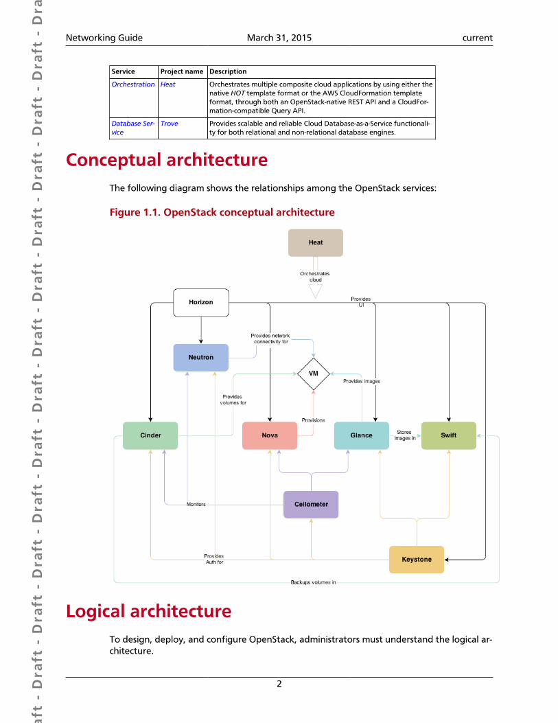
Conceptual architectureThe following diagram shows the relationships among the OpenStack services:
Figure 1.1. OpenStack conceptual architecture
Logical architectureTo design, deploy, and configure OpenStack, administrators must understand the logical ar-chitecture.
Dra
ft -
Dra
ft -
Dra
ft -
Dra
ft -
Dra
ft -
Dra
ft -
Dra
ft -
Dra
ft -
Dra
ft -
Dra
ft -
Dra
ft -
Dra
ft -
Dra
ft -
Dra
ft -
Dra
ft -
Dra
ft -
Dra
ft -
Dra
ft -
Dra
ft -
Dra
ft -
Dra
ft -
Dra
ft -
Dra
ft -
Dra
ft -
Dra
ft -
Dra
ft -
Dra
ft -
Dra
ft -
Dra
ft -
Dra
ft -
Dra
ft -
Dra
ft -
Dra
ft -
Dra
ft -
Dra
ft -
Networking Guide March 31, 2015 current
3
OpenStack modules are one of the following types:
Daemon Runs as a background process. On Linux platforms, adaemon is usually installed as a service.
Script Installs a virtual environment and runs tests. For exam-ple, the run_tests.sh script installs a virtual environ-ment and runs unit tests on a service.
Command-line interface (CLI) Enables users to submit API calls to OpenStack servicesthrough easy-to-use commands.
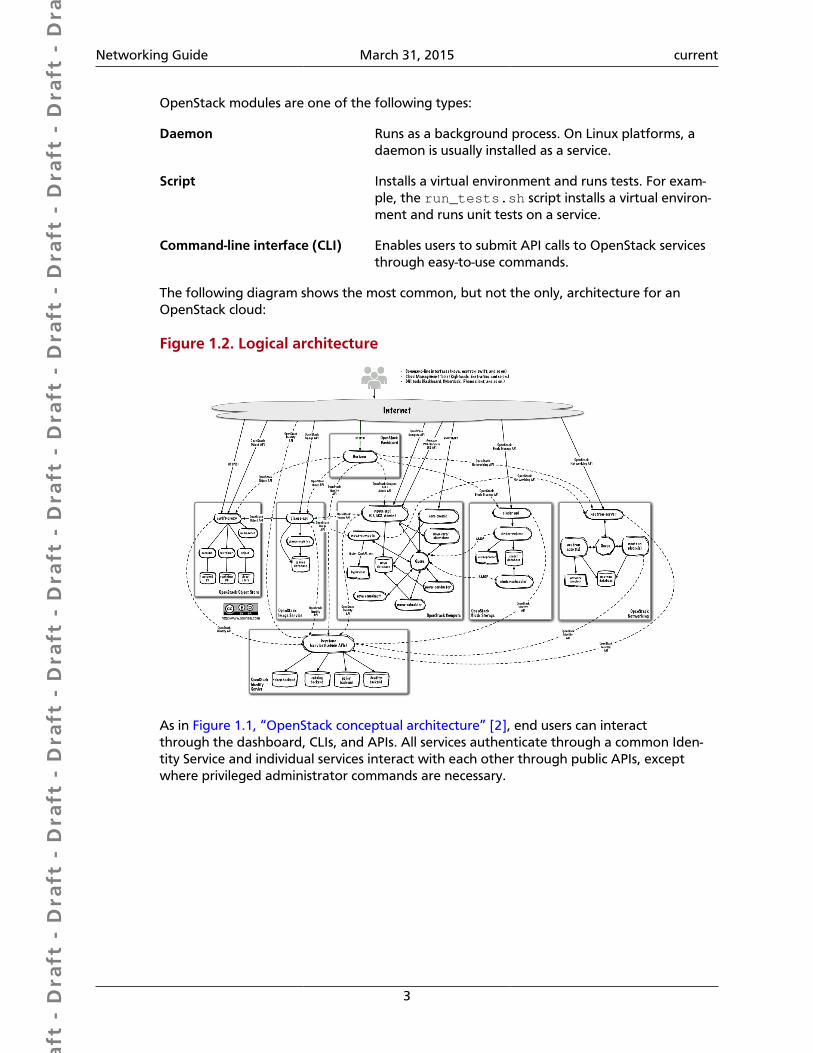
The following diagram shows the most common, but not the only, architecture for anOpenStack cloud:
Figure 1.2. Logical architecture
As in Figure 1.1, “OpenStack conceptual architecture” [2], end users can interactthrough the dashboard, CLIs, and APIs. All services authenticate through a common Iden-tity Service and individual services interact with each other through public APIs, exceptwhere privileged administrator commands are necessary.
Dra
ft -
Dra
ft -
Dra
ft -
Dra
ft -
Dra
ft -
Dra
ft -
Dra
ft -
Dra
ft -
Dra
ft -
Dra
ft -
Dra
ft -
Dra
ft -
Dra
ft -
Dra
ft -
Dra
ft -
Dra
ft -
Dra
ft -
Dra
ft -
Dra
ft -
Dra
ft -
Dra
ft -
Dra
ft -
Dra
ft -
Dra
ft -
Dra
ft -
Dra
ft -
Dra
ft -
Dra
ft -
Dra
ft -
Dra
ft -
Dra
ft -
Dra
ft -
Dra
ft -
Dra
ft -
Dra
ft -
Networking Guide March 31, 2015 current
4
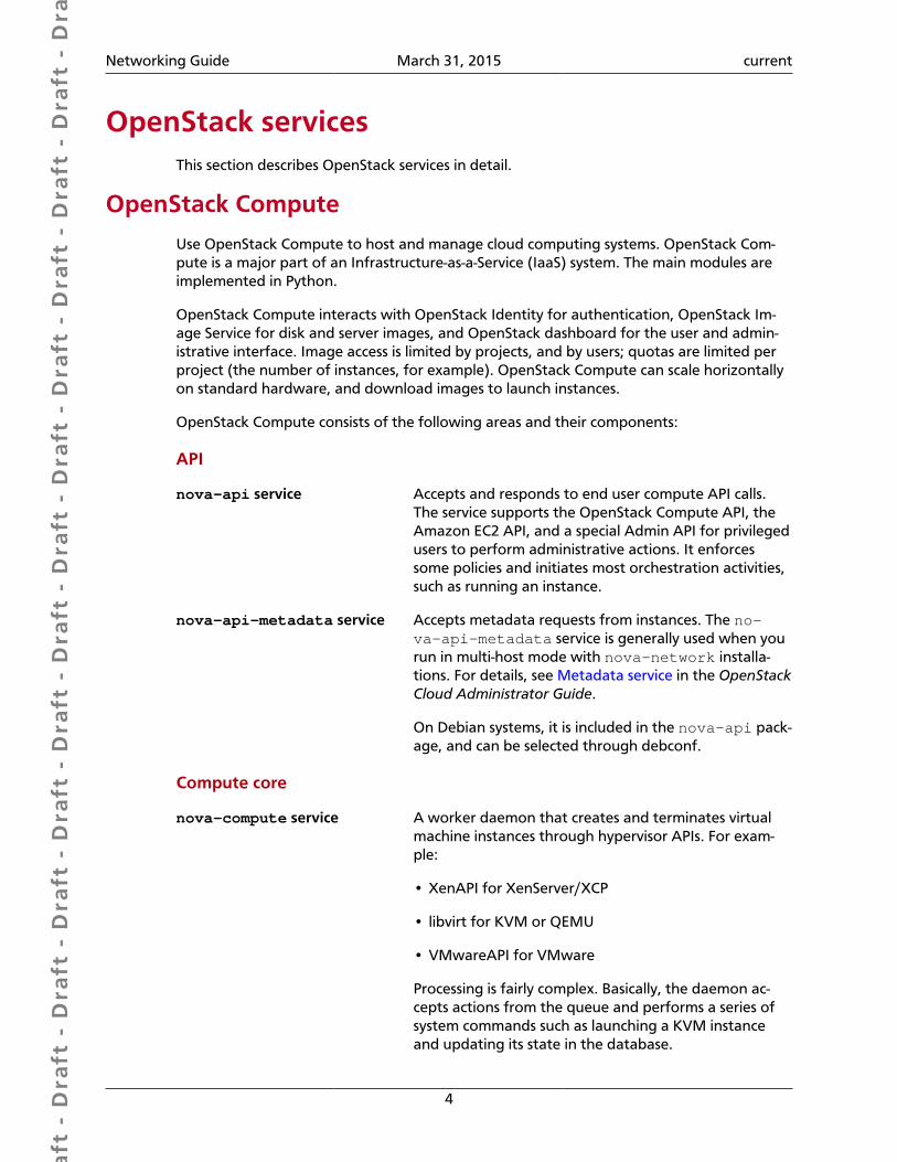
OpenStack servicesThis section describes OpenStack services in detail.
OpenStack Compute
Use OpenStack Compute to host and manage cloud computing systems. OpenStack Com-pute is a major part of an Infrastructure-as-a-Service (IaaS) system. The main modules areimplemented in Python.
OpenStack Compute interacts with OpenStack Identity for authentication, OpenStack Im-age Service for disk and server images, and OpenStack dashboard for the user and admin-istrative interface. Image access is limited by projects, and by users; quotas are limited perproject (the number of instances, for example). OpenStack Compute can scale horizontallyon standard hardware, and download images to launch instances.
OpenStack Compute consists of the following areas and their components:
API
nova-api service Accepts and responds to end user compute API calls.The service supports the OpenStack Compute API, theAmazon EC2 API, and a special Admin API for privilegedusers to perform administrative actions. It enforcessome policies and initiates most orchestration activities,such as running an instance.
nova-api-metadata service Accepts metadata requests from instances. The no-va-api-metadata service is generally used when yourun in multi-host mode with nova-network installa-tions. For details, see Metadata service in the OpenStackCloud Administrator Guide.
On Debian systems, it is included in the nova-api pack-age, and can be selected through debconf.
Compute core
nova-compute service A worker daemon that creates and terminates virtualmachine instances through hypervisor APIs. For exam-ple:
• XenAPI for XenServer/XCP
• libvirt for KVM or QEMU
• VMwareAPI for VMware
Processing is fairly complex. Basically, the daemon ac-cepts actions from the queue and performs a series ofsystem commands such as launching a KVM instanceand updating its state in the database.

Dra
ft -
Dra
ft -
Dra
ft -
Dra
ft -
Dra
ft -
Dra
ft -
Dra
ft -
Dra
ft -
Dra
ft -
Dra
ft -
Dra
ft -
Dra
ft -
Dra
ft -
Dra
ft -
Dra
ft -
Dra
ft -
Dra
ft -
Dra
ft -
Dra
ft -
Dra
ft -
Dra
ft -
Dra
ft -
Dra
ft -
Dra
ft -
Dra
ft -
Dra
ft -
Dra
ft -
Dra
ft -
Dra
ft -
Dra
ft -
Dra
ft -
Dra
ft -
Dra
ft -
Dra
ft -
Dra
ft -
Networking Guide March 31, 2015 current
5
nova-scheduler service Takes a virtual machine instance request from thequeue and determines on which compute server host itruns.
nova-conductor module Mediates interactions between the nova-compute ser-vice and the database. It eliminates direct accesses tothe cloud database made by the nova-compute ser-vice. The nova-conductor module scales horizontal-ly. However, do not deploy it on nodes where the no-va-compute service runs. For more information, see Anew Nova service: nova-conductor.
nova-cert module A server daemon that serves the Nova Cert service forX509 certificates. Used to generate certificates for eu-ca-bundle-image. Only needed for the EC2 API.
Networking for VMs
nova-network worker dae-mon
Similar to the nova-compute service, accepts network-ing tasks from the queue and manipulates the network.Performs tasks such as setting up bridging interfaces orchanging IPtables rules.

Dra
ft -
Dra
ft -
Dra
ft -
Dra
ft -
Dra
ft -
Dra
ft -
Dra
ft -
Dra
ft -
Dra
ft -
Dra
ft -
Dra
ft -
Dra
ft -
Dra
ft -
Dra
ft -
Dra
ft -
Dra
ft -
Dra
ft -
Dra
ft -
Dra
ft -
Dra
ft -
Dra
ft -
Dra
ft -
Dra
ft -
Dra
ft -
Dra
ft -
Dra
ft -
Dra
ft -
Dra
ft -
Dra
ft -
Dra
ft -
Dra
ft -
Dra
ft -
Dra
ft -
Dra
ft -
Dra
ft -
Networking Guide March 31, 2015 current
6
Console interface
nova-consoleauth daemon Authorizes tokens for users that console proxies pro-vide. See nova-novncproxy and nova-xvpn-vcproxy. This service must be running for console prox-ies to work. You can run proxies of either type against asingle nova-consoleauth service in a cluster configu-ration. For information, see About nova-consoleauth.
nova-novncproxy daemon Provides a proxy for accessing running instancesthrough a VNC connection. Supports browser-basednovnc clients.
nova-spicehtml5proxy dae-mon
Provides a proxy for accessing running instancesthrough a SPICE connection. Supports browser-basedHTML5 client.
nova-xvpnvncproxy daemon Provides a proxy for accessing running instancesthrough a VNC connection. Supports an OpenStack-spe-cific Java client.
nova-cert daemon x509 certificates.
In Debian, a unique nova-consoleproxy package provides the nova-novncproxy, no-va-spicehtml5proxy, and nova-xvpvncproxy packages. To select packages, edit the /etc/default/nova-consoleproxy file or use the debconf interface. You can also manuallyedit the /etc/default/nova-consoleproxy file, and stop and start the console dae-mons.
Image management (EC2 scenario)
nova-objectstore daemon An S3 interface for registering images with the Open-Stack Image Service. Used primarily for installations thatmust support euca2ools. The euca2ools tools talk tonova-objectstore in S3 language, and nova-ob-jectstore translates S3 requests into Image Servicerequests.
euca2ools client A set of command-line interpreter commands for man-aging cloud resources. Although it is not an OpenStackmodule, you can configure nova-api to support thisEC2 interface. For more information, see the Eucalyptus3.4 Documentation.
Command-line clients and other interfaces
nova client Enables users to submit commands as a tenant administrator or end user.
Other components
The queue A central hub for passing messages between daemons. Usually imple-mented with RabbitMQ, but can be implemented with an AMQP mes-sage queue, such as Apache Qpid or Zero MQ.
Dra
ft -
Dra
ft -
Dra
ft -
Dra
ft -
Dra
ft -
Dra
ft -
Dra
ft -
Dra
ft -
Dra
ft -
Dra
ft -
Dra
ft -
Dra
ft -
Dra
ft -
Dra
ft -
Dra
ft -
Dra
ft -
Dra
ft -
Dra
ft -
Dra
ft -
Dra
ft -
Dra
ft -
Dra
ft -
Dra
ft -
Dra
ft -
Dra
ft -
Dra
ft -
Dra
ft -
Dra
ft -
Dra
ft -
Dra
ft -
Dra
ft -
Dra
ft -
Dra
ft -
Dra
ft -
Dra
ft -
Networking Guide March 31, 2015 current
7
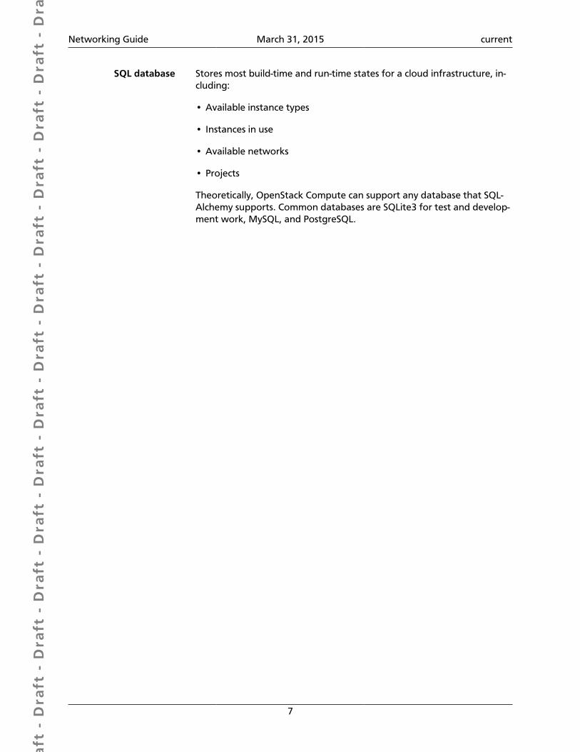
SQL database Stores most build-time and run-time states for a cloud infrastructure, in-cluding:
• Available instance types
• Instances in use
• Available networks
• Projects
Theoretically, OpenStack Compute can support any database that SQL-Alchemy supports. Common databases are SQLite3 for test and develop-ment work, MySQL, and PostgreSQL.
Dra
ft -
Dra
ft -
Dra
ft -
Dra
ft -
Dra
ft -
Dra
ft -
Dra
ft -
Dra
ft -
Dra
ft -
Dra
ft -
Dra
ft -
Dra
ft -
Dra
ft -
Dra
ft -
Dra
ft -
Dra
ft -
Dra
ft -
Dra
ft -
Dra
ft -
Dra
ft -
Dra
ft -
Dra
ft -
Dra
ft -
Dra
ft -
Dra
ft -
Dra
ft -
Dra
ft -
Dra
ft -
Dra
ft -
Dra
ft -
Dra
ft -
Dra
ft -
Dra
ft -
Dra
ft -
Dra
ft -
Networking Guide March 31, 2015 current
8
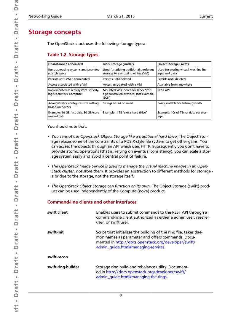
Storage concepts
The OpenStack stack uses the following storage types:
Table 1.2. Storage types
On-instance / ephemeral Block storage (cinder) Object Storage (swift)
Runs operating systems and providesscratch space
Used for adding additional persistentstorage to a virtual machine (VM)
Used for storing virtual machine im-ages and data
Persists until VM is terminated Persists until deleted Persists until deleted
Access associated with a VM Access associated with a VM Available from anywhere
Implemented as a filesystem underly-ing OpenStack Compute
Mounted via OpenStack Block Stor-age controlled protocol (for example,iSCSI)
REST API
Administrator configures size setting,based on flavors
Sizings based on need Easily scalable for future growth
Example: 10 GB first disk, 30 GB/coresecond disk
Example: 1 TB "extra hard drive" Example: 10s of TBs of data set stor-age
You should note that:
• You cannot use OpenStack Object Storage like a traditional hard drive. The Object Stor-age relaxes some of the constraints of a POSIX-style file system to get other gains. Youcan access the objects through an API which uses HTTP. Subsequently you don't have toprovide atomic operations (that is, relying on eventual consistency), you can scale a stor-age system easily and avoid a central point of failure.
• The OpenStack Image Service is used to manage the virtual machine images in an Open-Stack cluster, not store them. It provides an abstraction to different methods for storage -a bridge to the storage, not the storage itself.
• The OpenStack Object Storage can function on its own. The Object Storage (swift) prod-uct can be used independently of the Compute (nova) product.
Command-line clients and other interfaces
swift client Enables users to submit commands to the REST API through acommand-line client authorized as either a admin user, reselleruser, or swift user.
swift-init Script that initializes the building of the ring file, takes dae-mon names as parameter and offers commands. Docu-mented in http://docs.openstack.org/developer/swift/admin_guide.html#managing-services.
swift-recon
swift-ring-builder Storage ring build and rebalance utility. Document-ed in http://docs.openstack.org/developer/swift/admin_guide.html#managing-the-rings.
Dra
ft -
Dra
ft -
Dra
ft -
Dra
ft -
Dra
ft -
Dra
ft -
Dra
ft -
Dra
ft -
Dra
ft -
Dra
ft -
Dra
ft -
Dra
ft -
Dra
ft -
Dra
ft -
Dra
ft -
Dra
ft -
Dra
ft -
Dra
ft -
Dra
ft -
Dra
ft -
Dra
ft -
Dra
ft -
Dra
ft -
Dra
ft -
Dra
ft -
Dra
ft -
Dra
ft -
Dra
ft -
Dra
ft -
Dra
ft -
Dra
ft -
Dra
ft -
Dra
ft -
Dra
ft -
Dra
ft -
Networking Guide March 31, 2015 current
9
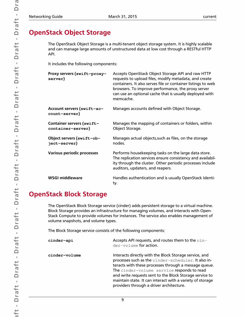
OpenStack Object Storage
The OpenStack Object Storage is a multi-tenant object storage system. It is highly scalableand can manage large amounts of unstructured data at low cost through a RESTful HTTPAPI.
It includes the following components:
Proxy servers (swift-proxy-server)
Accepts OpenStack Object Storage API and raw HTTPrequests to upload files, modify metadata, and createcontainers. It also serves file or container listings to webbrowsers. To improve performance, the proxy servercan use an optional cache that is usually deployed withmemcache.
Account servers (swift-ac-count-server)
Manages accounts defined with Object Storage.
Container servers (swift-container-server)
Manages the mapping of containers or folders, withinObject Storage.
Object servers (swift-ob-ject-server)
Manages actual objects,such as files, on the storagenodes.
Various periodic processes Performs housekeeping tasks on the large data store.The replication services ensure consistency and availabil-ity through the cluster. Other periodic processes includeauditors, updaters, and reapers.
WSGI middleware Handles authentication and is usually OpenStack Identi-ty.
OpenStack Block Storage
The OpenStack Block Storage service (cinder) adds persistent storage to a virtual machine.Block Storage provides an infrastructure for managing volumes, and interacts with Open-Stack Compute to provide volumes for instances. The service also enables management ofvolume snapshots, and volume types.
The Block Storage service consists of the following components:
cinder-api Accepts API requests, and routes them to the cin-der-volume for action.
cinder-volume Interacts directly with the Block Storage service, andprocesses such as the cinder-scheduler. It also in-teracts with these processes through a message queue.The cinder-volume service responds to readand write requests sent to the Block Storage service tomaintain state. It can interact with a variety of storageproviders through a driver architecture.

Dra
ft -
Dra
ft -
Dra
ft -
Dra
ft -
Dra
ft -
Dra
ft -
Dra
ft -
Dra
ft -
Dra
ft -
Dra
ft -
Dra
ft -
Dra
ft -
Dra
ft -
Dra
ft -
Dra
ft -
Dra
ft -
Dra
ft -
Dra
ft -
Dra
ft -
Dra
ft -
Dra
ft -
Dra
ft -
Dra
ft -
Dra
ft -
Dra
ft -
Dra
ft -
Dra
ft -
Dra
ft -
Dra
ft -
Dra
ft -
Dra
ft -
Dra
ft -
Dra
ft -
Dra
ft -
Dra
ft -
Networking Guide March 31, 2015 current
10
cinder-scheduler daemon Selects the optimal storage provider node on whichto create the volume. A similar component to the no-va-scheduler.
Messaging queue Routes information between the Block Storage process-es.
Dra
ft -
Dra
ft -
Dra
ft -
Dra
ft -
Dra
ft -
Dra
ft -
Dra
ft -
Dra
ft -
Dra
ft -
Dra
ft -
Dra
ft -
Dra
ft -
Dra
ft -
Dra
ft -
Dra
ft -
Dra
ft -
Dra
ft -
Dra
ft -
Dra
ft -
Dra
ft -
Dra
ft -
Dra
ft -
Dra
ft -
Dra
ft -
Dra
ft -
Dra
ft -
Dra
ft -
Dra
ft -
Dra
ft -
Dra
ft -
Dra
ft -
Dra
ft -
Dra
ft -
Dra
ft -
Dra
ft -
Networking Guide March 31, 2015 current
11
OpenStack Networking
OpenStack Networking allows you to create and attach interface devices managed by oth-er OpenStack services to networks. Plug-ins can be implemented to accommodate differentnetworking equipment and software, providing flexibility to OpenStack architecture anddeployment.
It includes the following components:
neutron-server Accepts and routes API requests to the appropriateOpenStack Networking plug-in for action.
OpenStack Networking plug-insand agents
Plugs and unplugs ports, creates networks or subnets,and provides IP addressing. These plug-ins and agentsdiffer depending on the vendor and technologies usedin the particular cloud. OpenStack Networking shipswith plug-ins and agents for Cisco virtual and physicalswitches, NEC OpenFlow products, Open vSwitch, Linuxbridging, and the VMware NSX product.
The common agents are L3 (layer 3), DHCP (dynamichost IP addressing), and a plug-in agent.
Messaging queue Used by most OpenStack Networking installations toroute information between the neutron-server and var-ious agents, as well as a database to store networkingstate for particular plug-ins.
OpenStack Networking mainly interacts with OpenStack Compute to provide networks andconnectivity for its instances.
Dra
ft -
Dra
ft -
Dra
ft -
Dra
ft -
Dra
ft -
Dra
ft -
Dra
ft -
Dra
ft -
Dra
ft -
Dra
ft -
Dra
ft -
Dra
ft -
Dra
ft -
Dra
ft -
Dra
ft -
Dra
ft -
Dra
ft -
Dra
ft -
Dra
ft -
Dra
ft -
Dra
ft -
Dra
ft -
Dra
ft -
Dra
ft -
Dra
ft -
Dra
ft -
Dra
ft -
Dra
ft -
Dra
ft -
Dra
ft -
Dra
ft -
Dra
ft -
Dra
ft -
Dra
ft -
Dra
ft -
Networking Guide March 31, 2015 current
12
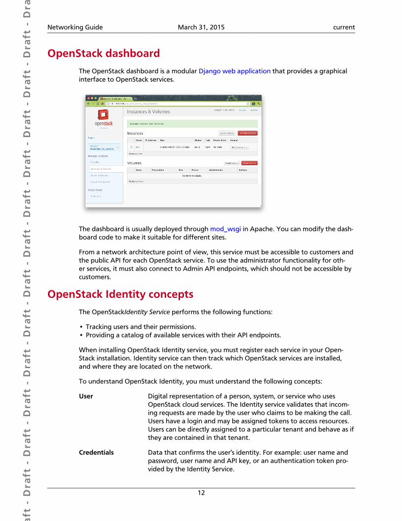
OpenStack dashboardThe OpenStack dashboard is a modular Django web application that provides a graphicalinterface to OpenStack services.
The dashboard is usually deployed through mod_wsgi in Apache. You can modify the dash-board code to make it suitable for different sites.
From a network architecture point of view, this service must be accessible to customers andthe public API for each OpenStack service. To use the administrator functionality for oth-er services, it must also connect to Admin API endpoints, which should not be accessible bycustomers.
OpenStack Identity conceptsThe OpenStackIdentity Service performs the following functions:
• Tracking users and their permissions.• Providing a catalog of available services with their API endpoints.
When installing OpenStack Identity service, you must register each service in your Open-Stack installation. Identity service can then track which OpenStack services are installed,and where they are located on the network.
To understand OpenStack Identity, you must understand the following concepts:
User Digital representation of a person, system, or service who usesOpenStack cloud services. The Identity service validates that incom-ing requests are made by the user who claims to be making the call.Users have a login and may be assigned tokens to access resources.Users can be directly assigned to a particular tenant and behave as ifthey are contained in that tenant.
Credentials Data that confirms the user's identity. For example: user name andpassword, user name and API key, or an authentication token pro-vided by the Identity Service.
Dra
ft -
Dra
ft -
Dra
ft -
Dra
ft -
Dra
ft -
Dra
ft -
Dra
ft -
Dra
ft -
Dra
ft -
Dra
ft -
Dra
ft -
Dra
ft -
Dra
ft -
Dra
ft -
Dra
ft -
Dra
ft -
Dra
ft -
Dra
ft -
Dra
ft -
Dra
ft -
Dra
ft -
Dra
ft -
Dra
ft -
Dra
ft -
Dra
ft -
Dra
ft -
Dra
ft -
Dra
ft -
Dra
ft -
Dra
ft -
Dra
ft -
Dra
ft -
Dra
ft -
Dra
ft -
Dra
ft -
Networking Guide March 31, 2015 current
13
Authentication The process of confirming the identity of a user. OpenStack Identityconfirms an incoming request by validating a set of credentials sup-plied by the user.
These credentials are initially a user name and password, or a username and API key. When user credentials are validated, OpenStackIdentity issues an authentication token which the user provides insubsequent requests.
Token An alpha-numeric string of text used to access OpenStack APIs andresources. A token may be revoked at any time and is valid for a fi-nite duration.
While OpenStack Identity supports token-based authentication inthis release, the intention is to support additional protocols in the fu-ture. Its main purpose is to be an integration service, and not aspireto be a full-fledged identity store and management solution.
Tenant A container used to group or isolate resources. Tenants also groupor isolate identity objects. Depending on the service operator, a ten-ant may map to a customer, account, organization, or project.
Service An OpenStack service, such as Compute (nova), Object Storage(swift), or Image Service (glance). It provides one or more endpointsin which users can access resources and perform operations.
Endpoint A network-accessible address where you access a service, usually aURL address. If you are using an extension for templates, an end-point template can be created, which represents the templates of allthe consumable services that are available across the regions.
Role A personality with a defined set of user rights and privileges to per-form a specific set of operations.
In the Identity service, a token that is issued to a user includes thelist of roles. Services that are being called by that user determinehow they interpret the set of roles a user has and to which opera-tions or resources each role grants access.
Keystone Client A command line interface for the OpenStack Identity API. For exam-ple, users can run the keystone service-create and keystone end-point-create commands to register services in their OpenStack instal-lations.
The following diagram shows the OpenStack Identity process flow:

Dra
ft -
Dra
ft -
Dra
ft -
Dra
ft -
Dra
ft -
Dra
ft -
Dra
ft -
Dra
ft -
Dra
ft -
Dra
ft -
Dra
ft -
Dra
ft -
Dra
ft -
Dra
ft -
Dra
ft -
Dra
ft -
Dra
ft -
Dra
ft -
Dra
ft -
Dra
ft -
Dra
ft -
Dra
ft -
Dra
ft -
Dra
ft -
Dra
ft -
Dra
ft -
Dra
ft -
Dra
ft -
Dra
ft -
Dra
ft -
Dra
ft -
Dra
ft -
Dra
ft -
Dra
ft -
Dra
ft -
Networking Guide March 31, 2015 current
14
Dra
ft -
Dra
ft -
Dra
ft -
Dra
ft -
Dra
ft -
Dra
ft -
Dra
ft -
Dra
ft -
Dra
ft -
Dra
ft -
Dra
ft -
Dra
ft -
Dra
ft -
Dra
ft -
Dra
ft -
Dra
ft -
Dra
ft -
Dra
ft -
Dra
ft -
Dra
ft -
Dra
ft -
Dra
ft -
Dra
ft -
Dra
ft -
Dra
ft -
Dra
ft -
Dra
ft -
Dra
ft -
Dra
ft -
Dra
ft -
Dra
ft -
Dra
ft -
Dra
ft -
Dra
ft -
Dra
ft -
Networking Guide March 31, 2015 current
15
OpenStack Image Service
The OpenStack Image Service is central to Infrastructure-as-a-Service (IaaS) as shown in thesection called “Conceptual architecture” [2]. It accepts API requests for disk or server im-ages, and image metadata from end users or OpenStack Compute components. It also sup-ports the storage of disk or server images on various repository types, including OpenStackObject Storage.
A number of periodic processes run on the OpenStack Image Service to support caching.Replication services ensure consistency and availability through the cluster. Other periodicprocesses include auditors, updaters, and reapers.
The OpenStack Image Service includes the following components:
glance-api Accepts Image API calls for image discovery, retrieval,and storage.
glance-registry Stores, processes, and retrieves metadata about images.Metadata includes items such as size and type.
Security note
The registry is a private internal servicemeant for use by OpenStack Image Service.Do not disclose it to users.
Database Stores image metadata and you can choose yourdatabase depending on your preference. Most deploy-ments use MySQL or SQLite.
Storage repository for imagefiles
Various repository types are supported including nor-mal file systems, Object Storage, RADOS block devices,HTTP, and Amazon S3. Note that some repositories willonly support read-only usage.
Telemetry module
The Telemetry module performs the following functions:
• Efficiently collects the metering data about the CPU and network costs.
• Collects data by monitoring notifications sent from services or by polling the infrastruc-ture.
• Configures the type of collected data to meet various operating requirements. It accessesand inserts the metering data through the REST API.
• Expands the framework to collect custom usage data by additional plug-ins.
• Produces signed metering messages that cannot be repudiated.
The Telemetry module consists of the following components:
Dra
ft -
Dra
ft -
Dra
ft -
Dra
ft -
Dra
ft -
Dra
ft -
Dra
ft -
Dra
ft -
Dra
ft -
Dra
ft -
Dra
ft -
Dra
ft -
Dra
ft -
Dra
ft -
Dra
ft -
Dra
ft -
Dra
ft -
Dra
ft -
Dra
ft -
Dra
ft -
Dra
ft -
Dra
ft -
Dra
ft -
Dra
ft -
Dra
ft -
Dra
ft -
Dra
ft -
Dra
ft -
Dra
ft -
Dra
ft -
Dra
ft -
Dra
ft -
Dra
ft -
Dra
ft -
Dra
ft -
Networking Guide March 31, 2015 current
16
A compute agent (ceilome-ter-agent-compute)
Runs on each compute node and polls for resource uti-lization statistics. There may be other types of agents inthe future, but for now our focus is creating the com-pute agent.
A central agent (ceilome-ter-agent-central)
Runs on a central management server to poll for re-source utilization statistics for resources not tied to in-stances or compute nodes.
A notification agent (ceilome-ter-agent-notification)
Runs on a central management server to initiate alarmactions, such as calling out to a webhook with a descrip-tion of the alarm state transition.
A collector (ceilometer-col-lector)
Runs on central management server(s) to monitor themessage queues (for notifications and for metering da-ta coming from the agent). Notification messages areprocessed and turned into metering messages, whichare sent to the message bus using the appropriate topic.Telemetry messages are written to the data store with-out modification.
An alarm evaluator (ceilome-ter-alarm-evaluator)
Runs on one or more central management servers to de-termine when alarms fire due to the associated statistictrend crossing a threshold over a sliding time window.
An alarm notifier (ceilome-ter-alarm-notifier)
Runs on one or more central management servers to al-low alarms to be set based on the threshold evaluationfor a collection of samples.
A data store A database capable of handling concurrent writes (fromone or more collector instances) and reads (from theAPI server).
An API server (ceilome-ter-api)
Runs on one or more central management servers toprovide data access from the data store.
These services communicate by using the OpenStack messaging bus. Only the collector andAPI server have access to the data store.
Orchestration module concepts
The Orchestration module provides a template-based orchestration for describing a cloudapplication, by running OpenStack API calls to generate running cloud applications. Thesoftware integrates other core components of OpenStack into a one-file template system.The templates allow you to create most OpenStack resource types, such as instances, float-ing IPs, volumes, security groups and users. It also provides advanced functionality, such asinstance high availability, instance auto-scaling, and nested stacks. This enables OpenStackcore projects to receive a larger user base.
The service enables deployers to integrate with the Orchestration module directly orthrough custom plug-ins.
The Orchestration module consists of the following components:
Dra
ft -
Dra
ft -
Dra
ft -
Dra
ft -
Dra
ft -
Dra
ft -
Dra
ft -
Dra
ft -
Dra
ft -
Dra
ft -
Dra
ft -
Dra
ft -
Dra
ft -
Dra
ft -
Dra
ft -
Dra
ft -
Dra
ft -
Dra
ft -
Dra
ft -
Dra
ft -
Dra
ft -
Dra
ft -
Dra
ft -
Dra
ft -
Dra
ft -
Dra
ft -
Dra
ft -
Dra
ft -
Dra
ft -
Dra
ft -
Dra
ft -
Dra
ft -
Dra
ft -
Dra
ft -
Dra
ft -
Networking Guide March 31, 2015 current
17
heat command-line client A CLI that communicates with the heat-api to run AWSCloudFormation APIs. End developers can directly usethe Orchestration REST API.
heat-api component An OpenStack-native REST API that processes API re-quests by sending them to the heat-engine over RemoteProcedure Call (RPC).
heat-api-cfn component An AWS Query API that is compatible with AWS Cloud-Formation. It processes API requests by sending them tothe heat-engine over RPC.
heat-engine Orchestrates the launching of templates and providesevents back to the API consumer.
Database service overviewThe Database service provides scalable and reliable cloud provisioning functionality for bothrelational and non-relational database engines. Users can quickly and easily use databasefeatures without the burden of handling complex administrative tasks. Cloud users anddatabase administrators can provision and manage multiple database instances as needed.
The Database service provides resource isolation at high performance levels, and automatescomplex administrative tasks such as deployment, configuration, patching, backups, re-stores, and monitoring.
Process flow example. This example is a high-level process flow for using Database ser-vices:
1. The OpenStack Administrator configures the basic infrastructure using the followingsteps:
a. Install the Database service.
b. Create an image for each type of database. For example, one for MySQL and onefor MongoDB.
c. Use the trove-manage command to import images and offer them to tenants.
2. The OpenStack end user deploys the Database service using the following steps:
a. Create a Database service instance using the trove create command.
b. Use the trove list command to get the ID of the instance, followed by the troveshow command to get the IP address of it.
c. Access the Database service instance using typical database access commands. Forexample, with MySQL:
$ mysql -u myuser -p -h TROVE_IP_ADDRESS mydb
The Database service includes the following components:
python-troveclient com-mand-line client
A CLI that communicates with the trove-api compo-nent.

Dra
ft -
Dra
ft -
Dra
ft -
Dra
ft -
Dra
ft -
Dra
ft -
Dra
ft -
Dra
ft -
Dra
ft -
Dra
ft -
Dra
ft -
Dra
ft -
Dra
ft -
Dra
ft -
Dra
ft -
Dra
ft -
Dra
ft -
Dra
ft -
Dra
ft -
Dra
ft -
Dra
ft -
Dra
ft -
Dra
ft -
Dra
ft -
Dra
ft -
Dra
ft -
Dra
ft -
Dra
ft -
Dra
ft -
Dra
ft -
Dra
ft -
Dra
ft -
Dra
ft -
Dra
ft -
Dra
ft -
Networking Guide March 31, 2015 current
18
trove-api component Provides an OpenStack-native RESTful API that supportsJSON to provision and manage Trove instances.
trove-conductor service Runs on the host, and receives messages from guest in-stances that want to update information on the host.
trove-taskmanager service Instruments the complex system flows that support pro-visioning instances, managing the lifecycle of instances,and performing operations on instances.
trove-guestagent service Runs within the guest instance. Manages and performsoperations on the database itself.
Data processing service
The Data processing service for OpenStack (sahara) aims to provide users with a simplemeans to provision data processing (Hadoop, Spark) clusters by specifying several parame-ters like Hadoop version, cluster topology, node hardware details and a few more. After auser fills in all the parameters, the Data processing service deploys the cluster in a few min-utes. Sahara also provides a means to scale already provisioned clusters by adding/remov-ing worker nodes on demand.
The solution addresses the following use cases:
• Fast provisioning of Hadoop clusters on OpenStack for development and QA.
• Utilization of unused compute power from general purpose OpenStack IaaS cloud.
• Analytics-as-a-Service for ad-hoc or bursty analytic workloads.
Key features are:
• Designed as an OpenStack component.
• Managed through REST API with UI available as part of OpenStack dashboard.
• Support for different Hadoop distributions:
• Pluggable system of Hadoop installation engines.
• Integration with vendor specific management tools, such as Apache Ambari or Cloud-era Management Console.
• Predefined templates of Hadoop configurations with the ability to modify parameters.
• User-friendly UI for ad-hoc analytics queries based on Hive or Pig.
FeedbackTo provide feedback on documentation, join and use the<[email protected]> mailing list at OpenStack DocumentationMailing List, or report a bug.
Dra
ft -
Dra
ft -
Dra
ft -
Dra
ft -
Dra
ft -
Dra
ft -
Dra
ft -
Dra
ft -
Dra
ft -
Dra
ft -
Dra
ft -
Dra
ft -
Dra
ft -
Dra
ft -
Dra
ft -
Dra
ft -
Dra
ft -
Dra
ft -
Dra
ft -
Dra
ft -
Dra
ft -
Dra
ft -
Dra
ft -
Dra
ft -
Dra
ft -
Dra
ft -
Dra
ft -
Dra
ft -
Dra
ft -
Dra
ft -
Dra
ft -
Dra
ft -
Dra
ft -
Dra
ft -
Dra
ft -
Networking Guide March 31, 2015 current
19
2. Introduction to networking
Table of ContentsNetworking layers ......................................................................................................... 19Switches ........................................................................................................................ 20Routers ......................................................................................................................... 20Firewalls ........................................................................................................................ 20Tunnel (segmentation) technologies .............................................................................. 21Namespaces .................................................................................................................. 21Neutron data model ..................................................................................................... 21
The OpenStack Networking service provides an API that allows users to set up and definenetwork connectivity and addressing in the cloud. The project code-name for Networkingservices is neutron. OpenStack Networking handles the creation and management of a vir-tual networking infrastructure, including networks, switches, subnets, and routers for de-vices managed by the OpenStack Compute service (nova). Advanced services such as fire-walls or virtual private networks (VPNs) can also be used.
OpenStack Networking consists of the neutron-server, a database for persistent stor-age, and any number of plugin agents, which provide other services such as interfacingwith native Linux networking mechanisms, external devices, or SDN controllers.
OpenStack Networking is entirely standalone and can be deployed to a dedicated host. Ifyour deployment uses a controller host to run centralized Compute components, you candeploy the Networking server to that specific host instead.
OpenStack Networking integrates with various other OpenStack components:
• OpenStack Identity (keystone) is used for authentication and authorization of API re-quests.
• OpenStack Compute (nova) is used to plug each virtual NIC on the VM into a particularnetwork.
• OpenStack dashboard (horizon) for administrators and tenant users to create and man-age network services through a web-based graphical interface.
Networking layersNetwork communication is commonly described in terms of the OSI model. The OSI modelis a seven-layer model that describes how various protocols and mechanisms fit together.Each layer depends on the protocols in the layer beneath it.
7 Application The Application layer of the OSI model is the user interface layer.Everything here is application specific. Some examples at this layerwhich could be Telnet, FTP, email.
6 Presentation Here is where data gets translated from the application into networkformat and back again. The presentation layer transforms data into a
Dra
ft -
Dra
ft -
Dra
ft -
Dra
ft -
Dra
ft -
Dra
ft -
Dra
ft -
Dra
ft -
Dra
ft -
Dra
ft -
Dra
ft -
Dra
ft -
Dra
ft -
Dra
ft -
Dra
ft -
Dra
ft -
Dra
ft -
Dra
ft -
Dra
ft -
Dra
ft -
Dra
ft -
Dra
ft -
Dra
ft -
Dra
ft -
Dra
ft -
Dra
ft -
Dra
ft -
Dra
ft -
Dra
ft -
Dra
ft -
Dra
ft -
Dra
ft -
Dra
ft -
Dra
ft -
Dra
ft -
Networking Guide March 31, 2015 current
20
form that the application layer can accept. The presentation layer for-mats and encrypts data which prevents compatibility problems.
5 Session The Session layer manages connections between applications. It is re-sponsible for session and connection coordination.
4 Transport This layer deals with transporting data usually over TCP or Transmis-sion Control Protocol. TCP enables two hosts to establish, connect,and exchange streams of data together. TCP also guarantees deliveryof data and the order in which packets are sent.
3 Network This layer handles transmission for data from node to node. The net-work layer handles routing, forwarding, addressing, inter-networking,and error handling. Usually this is the IP portion of TCP/IP.
2 Data link The data link layer is where most LAN technologies such as Ethernetlive. This layer is divided into two sub layers: MAC (Media Access Con-trol): Handles access to data and permissions to translate it. LLC (Logi-cal Link Control): Manages traffic across the physical layer.
1 Physical The physical layer is the description of the physical media or signalsused in networking. Examples include the size of the Ethernet, hubs,or other physical devices used to establish a network.
OpenStack Networking is primarily concerned with Layer 2 and Layer 3.
Layer-3 protocols include the Internet Protocol Suite, which includes IPv4, IPv6, and the In-ternet Control Message Protocol (ICMP).
SwitchesA switch is a device that is used to connect devices on a network. Switches forward packetson to other devices, using packet switching to pass data along only to devices that need toreceive it. Switches operate at Layer 2 of the OSI model.
RoutersA router is a networking device that connects multiple networks together. Routers are con-nected to two or more networks. When they receive data packets, they use a routing tableto determine which networks to pass the information to.
FirewallsA firewall is a network security system that controls the network traffic using a set of rules.Firewalls can be implemented in both hardware and software, or a mix of the two. For ex-ample, a firewall might disallow traffic originating from a range of IP addresses or only al-low traffic on specific ports. Firewalls are often used between internal networks, where da-ta is trusted, and on external networks such as the Internet.
Many firewalls incorporate Network Address Translation (NAT). Network address transla-tion masks the IP addresses of the devices on the internal network, so that external devicessee only the single public IP address of the device hosting the firewall.
Dra
ft -
Dra
ft -
Dra
ft -
Dra
ft -
Dra
ft -
Dra
ft -
Dra
ft -
Dra
ft -
Dra
ft -
Dra
ft -
Dra
ft -
Dra
ft -
Dra
ft -
Dra
ft -
Dra
ft -
Dra
ft -
Dra
ft -
Dra
ft -
Dra
ft -
Dra
ft -
Dra
ft -
Dra
ft -
Dra
ft -
Dra
ft -
Dra
ft -
Dra
ft -
Dra
ft -
Dra
ft -
Dra
ft -
Dra
ft -
Dra
ft -
Dra
ft -
Dra
ft -
Dra
ft -
Dra
ft -
Networking Guide March 31, 2015 current
21
Tunnel (segmentation) technologiesTunneling allows one network protocol to encapsulate another payload protocol, such thatpackets from the payload protocol are passed as data on the delivery protocol. This can beused, for example, to pass data securely over an untrusted network.
Layer 2
Virtual local area network(VLAN)
A VLAN partitions a single layer-2 network into multipleisolated broadcast domains.
Layer 3
Generic routing encapsulation(GRE)
GRE carries IP packets with private IP address over theInternet using delivery packets with public IP addresses.
Virtual extensible local areanetwork (VXLAN)
VXLAN encapsulates layer-2 Ethernet frames over lay-er-4 UDP packets.
NamespacesA namespace is a container for a set of identifiers. Namespaces provide a level of direc-tion to specific identifiers and make it possible to differentiate between identifiers withthe same exact name. With network namespaces, you can have different and separate in-stances of network interfaces and routing tables that operate separate from each other.
Neutron data modelFIXME: Explain Neutron terminology and how it maps to networking concepts presentedin previous chapters. A small amount of terminology is at http://docs.openstack.org/ad-min-guide-cloud/content/api_abstractions.html . Probably not worth subsections as out-lined here. table or variablelist?
Networks
FIXME
Subnets
FIXME
Ports
FIXME
Extensions
FIXME
Dra
ft -
Dra
ft -
Dra
ft -
Dra
ft -
Dra
ft -
Dra
ft -
Dra
ft -
Dra
ft -
Dra
ft -
Dra
ft -
Dra
ft -
Dra
ft -
Dra
ft -
Dra
ft -
Dra
ft -
Dra
ft -
Dra
ft -
Dra
ft -
Dra
ft -
Dra
ft -
Dra
ft -
Dra
ft -
Dra
ft -
Dra
ft -
Dra
ft -
Dra
ft -
Dra
ft -
Dra
ft -
Dra
ft -
Dra
ft -
Dra
ft -
Dra
ft -
Dra
ft -
Dra
ft -
Dra
ft -
Networking Guide March 31, 2015 current
22
3. Networking architecture
Table of ContentsTenant and provider networks ...................................................................................... 22VMware NSX integration .............................................................................................. 23Overview ....................................................................................................................... 23Server ............................................................................................................................ 24Plug-ins .......................................................................................................................... 24Agents .......................................................................................................................... 24
A standard network architecture design includes a cloud controller host, a network gate-way host, and a number of hypervisors for hosting virtual machines. The cloud controllerand network gateway can be on the same host. However, if you expect VMs to send sig-nificant traffic to or from the Internet, a dedicated network gateway host helps avoid CPUcontention between the neutron-l3-agent and other OpenStack services that forwardpackets.
You can run OpenStack Networking across multiple physical devices. It is also possible torun all service daemons on a single physical host for evaluation purposes. However, this isnot generally robust enough for production purposes. For greater redundancy, you can runeach service on a dedicated physical host and replicate any essential services across multiplehosts.
For more information about networking architecture options, see the Network Design sec-tion of the OpenStack Operations Guide.
A standard OpenStack Networking deployment usually includes one or more of the follow-ing physical networks:
Table 3.1. General distinct physical data center networks
Network Description
Management net-work
Provides internal communication between OpenStack components. IP addresses on this net-work should be reachable only within the data center.
Data network Provides VM data communication within the cloud deployment. The IP addressing require-ments of this network depend on the Networking plug-in that is used.
External network Provides VMs with Internet access in some deployment scenarios. Anyone on the Internet canreach IP addresses on this network.
API network Exposes all OpenStack APIs, including the Networking API, to tenants. IP addresses on this net-work should be reachable by anyone on the Internet. The API network might be the same asthe external network because it is possible to create an external-network subnet that has allo-cated IP ranges, which use less than the full range of IP addresses in an IP block.
Tenant and provider networksThe following diagram presents an overview of the tenant and provider network types,and illustrates how they interact within the overall Networking topology:
Dra
ft -
Dra
ft -
Dra
ft -
Dra
ft -
Dra
ft -
Dra
ft -
Dra
ft -
Dra
ft -
Dra
ft -
Dra
ft -
Dra
ft -
Dra
ft -
Dra
ft -
Dra
ft -
Dra
ft -
Dra
ft -
Dra
ft -
Dra
ft -
Dra
ft -
Dra
ft -
Dra
ft -
Dra
ft -
Dra
ft -
Dra
ft -
Dra
ft -
Dra
ft -
Dra
ft -
Dra
ft -
Dra
ft -
Dra
ft -
Dra
ft -
Dra
ft -
Dra
ft -
Dra
ft -
Dra
ft -
Networking Guide March 31, 2015 current
23
Tenant networks. Users create tenant networks for connectivity within projects; theyare fully isolated by default and are not shared with other projects. Networking supports arange of tenant network types:
Flat All instances reside on the same network, which can also be sharedwith the hosts. No VLAN tagging or other network segregation takesplace.
Local Instances reside on the local compute host and are effectively isolatedfrom any external networks.
VLAN Networking allows users to create multiple provider or tenant net-works using VLAN IDs (802.1Q tagged) that correspond to VLANspresent in the physical network. This allows instances to communicatewith each other across the environment. They can also communicatewith dedicated servers, firewalls, load balancers, and other networkinginfrastructure on the same layer 2 VLAN.
VXLAN and GRE VXLAN and GRE use network overlays to support private communica-tion between instances. A Networking router is required to enable traf-fic to traverse outside of the GRE or VXLAN tenant network. A routeris also required to connect directly-connected tenant networks with ex-ternal networks, including the Internet. The router provides the abilityto connect to instances directly from an external network using float-ing IP addresses.
Provider networks. The OpenStack administrator creates provider networks. These net-works map to existing physical networks in the data center. Useful network types in thiscategory are flat (untagged) and VLAN (802.1Q tagged). It is possible to share providernetworks among tenants as part of the network creation process.
VMware NSX integrationOpenStack Networking uses the NSX plug-in for Networking to integrate with an existingVMware vCenter deployment. When installed on the network nodes, the NSX plug-in en-ables a NSX controller to centrally manage configuration settings and push them to man-aged network nodes. Network nodes are considered managed when they're added as hy-pervisors to the NSX controller.
The following diagram depicts an example NSX deployment and illustrates the route in-ter-VM traffic takes between separate Compute nodes. Note the placement of the VMwareNSX plug-in and the neutron-server service on the network node. The NSX controllerfeatures centrally with a green line to the network node to indicate the management rela-tionship:
OverviewBacon ipsum dolor sit amet biltong meatloaf andouille, turducken bresaola pork belly beefribs ham hock capicola tail prosciutto landjaeger meatball pork loin. Swine turkey jowl,porchetta doner boudin meatloaf. Shoulder capicola prosciutto, shank landjaeger shortribs sirloin turducken pork belly boudin frankfurter chuck. Salami shankle bresaola cow filetmignon ham hock shank.
Dra
ft -
Dra
ft -
Dra
ft -
Dra
ft -
Dra
ft -
Dra
ft -
Dra
ft -
Dra
ft -
Dra
ft -
Dra
ft -
Dra
ft -
Dra
ft -
Dra
ft -
Dra
ft -
Dra
ft -
Dra
ft -
Dra
ft -
Dra
ft -
Dra
ft -
Dra
ft -
Dra
ft -
Dra
ft -
Dra
ft -
Dra
ft -
Dra
ft -
Dra
ft -
Dra
ft -
Dra
ft -
Dra
ft -
Dra
ft -
Dra
ft -
Dra
ft -
Dra
ft -
Dra
ft -
Dra
ft -
Networking Guide March 31, 2015 current
24
Service/component hierarchy
Neutron server -> plug-in -> agents
Example architectures
XIncluded below from Cloud Admin Guide. May need to be reworked. See also http://docs.openstack.org/grizzly/openstack-network/admin/content/use_cases.html and ad-min-guide-cloud/networking/section_networking-scenarios.xml .
ServerBacon ipsum dolor sit amet biltong meatloaf andouille, turducken bresaola pork belly beefribs ham hock capicola tail prosciutto landjaeger meatball pork loin. Swine turkey jowl,porchetta doner boudin meatloaf. Shoulder capicola prosciutto, shank landjaeger shortribs sirloin turducken pork belly boudin frankfurter chuck. Salami shankle bresaola cow filetmignon ham hock shank.
Plug-insThe legacy networking (nova-network) implementation assumed a basic model of isolationthrough Linux VLANs and IP tables. Networking introduces support for vendor plug-ins,which offer a custom back-end implementation of the Networking API. A plugin can usea variety of technologies to implement the logical API requests. Some networking plug-insmight use basic Linux VLANs and IP tables, while others might use more advanced technolo-gies, such as L2-in-L3 tunneling or OpenFlow, to provide similar benefits.
AgentsBacon ipsum dolor sit amet ribeye rump pork loin shankle jowl pancetta bacon. Chickenandouille capicola filet mignon shoulder, turducken corned beef boudin hamburger fat-back pork chop t-bone kevin. Leberkas turducken short loin t-bone pork belly pig prosciuttochicken beef ribs pork loin short ribs shoulder jerky bacon strip steak.
neutron-server A Python daemon, which manages user requests (and expos-es the API). It is configured with a plugin that implements theOpenStack Networking API operations using a specific set ofnetworking mechanisms. A wide choice of plugins are also avail-able. For example, the open vSwitch and linuxbridge plugins uti-lize native Linux networking mechanisms, while other plugins in-terface with external devices or SDN controllers.
neutron-l3-agent An agent providing L3/NAT forwarding.
neutron-*-agent A plug-in agent that runs on each node to perform local net-working configuration for the node's virtual machines and net-working services.
neutron-dhcp-agent An agent providing DHCP services to tenant networks.
Dra
ft -
Dra
ft -
Dra
ft -
Dra
ft -
Dra
ft -
Dra
ft -
Dra
ft -
Dra
ft -
Dra
ft -
Dra
ft -
Dra
ft -
Dra
ft -
Dra
ft -
Dra
ft -
Dra
ft -
Dra
ft -
Dra
ft -
Dra
ft -
Dra
ft -
Dra
ft -
Dra
ft -
Dra
ft -
Dra
ft -
Dra
ft -
Dra
ft -
Dra
ft -
Dra
ft -
Dra
ft -
Dra
ft -
Dra
ft -
Dra
ft -
Dra
ft -
Dra
ft -
Dra
ft -
Dra
ft -
Networking Guide March 31, 2015 current
25
Database Provides persistent storage.
Overview
provide layer-2/3 connectivity to instances, handle physical-virtual network transition, han-dle metadata, etc
Layer 2
Linux Bridge overview/concepts
configuration file
Open vSwitch overview/concepts
configuration file
Layer 3 (IP/Routing)
l3 overview/concepts
configuration file
DHCP overview/concepts
configuration file
Miscellaneous
Metadata overview/concepts
configuration file
Dra
ft -
Dra
ft -
Dra
ft -
Dra
ft -
Dra
ft -
Dra
ft -
Dra
ft -
Dra
ft -
Dra
ft -
Dra
ft -
Dra
ft -
Dra
ft -
Dra
ft -
Dra
ft -
Dra
ft -
Dra
ft -
Dra
ft -
Dra
ft -
Dra
ft -
Dra
ft -
Dra
ft -
Dra
ft -
Dra
ft -
Dra
ft -
Dra
ft -
Dra
ft -
Dra
ft -
Dra
ft -
Dra
ft -
Dra
ft -
Dra
ft -
Dra
ft -
Dra
ft -
Dra
ft -
Dra
ft -
Networking Guide March 31, 2015 current
26
4. Plugins
Table of ContentsML2 .............................................................................................................................. 26Proprietary .................................................................................................................... 27
Bacon ipsum dolor sit amet biltong meatloaf andouille, turducken bresaola pork belly beefribs ham hock capicola tail prosciutto landjaeger meatball pork loin. Swine turkey jowl,porchetta doner boudin meatloaf. Shoulder capicola prosciutto, shank landjaeger shortribs sirloin turducken pork belly boudin frankfurter chuck. Salami shankle bresaola cow filetmignon ham hock shank.
ML2
Overview
architecture
configuration file organization, relationships, etc
Network type drivers
Flat FIXME
VLAN FIXME
GRE FIXME
VXLAN FIXME
Tenant network types
• Local
• VLAN, VLAN ID ranges
• GRE, Tunnel ID ranges
• VXLAN, VNI ID ranges
See admin-guide-cloud/networking/section_networking_arch.xml
Mechanisms
Linux Bridge FIXME
Open vSwitch FIXME
Dra
ft -
Dra
ft -
Dra
ft -
Dra
ft -
Dra
ft -
Dra
ft -
Dra
ft -
Dra
ft -
Dra
ft -
Dra
ft -
Dra
ft -
Dra
ft -
Dra
ft -
Dra
ft -
Dra
ft -
Dra
ft -
Dra
ft -
Dra
ft -
Dra
ft -
Dra
ft -
Dra
ft -
Dra
ft -
Dra
ft -
Dra
ft -
Dra
ft -
Dra
ft -
Dra
ft -
Dra
ft -
Dra
ft -
Dra
ft -
Dra
ft -
Dra
ft -
Dra
ft -
Dra
ft -
Dra
ft -
Networking Guide March 31, 2015 current
27
Open Daylight FIXME
L2 Population FIXME
Proprietary FIXME
Security
Options FIXME
ProprietaryFIXME
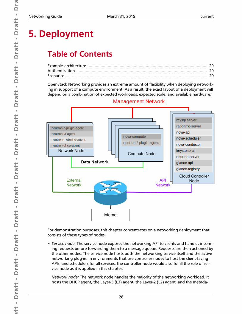
Dra
ft -
Dra
ft -
Dra
ft -
Dra
ft -
Dra
ft -
Dra
ft -
Dra
ft -
Dra
ft -
Dra
ft -
Dra
ft -
Dra
ft -
Dra
ft -
Dra
ft -
Dra
ft -
Dra
ft -
Dra
ft -
Dra
ft -
Dra
ft -
Dra
ft -
Dra
ft -
Dra
ft -
Dra
ft -
Dra
ft -
Dra
ft -
Dra
ft -
Dra
ft -
Dra
ft -
Dra
ft -
Dra
ft -
Dra
ft -
Dra
ft -
Dra
ft -
Dra
ft -
Dra
ft -
Dra
ft -
Networking Guide March 31, 2015 current
28
5. Deployment
Table of ContentsExample architecture ..................................................................................................... 29Authentication .............................................................................................................. 29Scenarios ....................................................................................................................... 29
OpenStack Networking provides an extreme amount of flexibility when deploying network-ing in support of a compute environment. As a result, the exact layout of a deployment willdepend on a combination of expected workloads, expected scale, and available hardware.
For demonstration purposes, this chapter concentrates on a networking deployment thatconsists of these types of nodes:
• Service node: The service node exposes the networking API to clients and handles incom-ing requests before forwarding them to a message queue. Requests are then actioned bythe other nodes. The service node hosts both the networking service itself and the activenetworking plug-in. In environments that use controller nodes to host the client-facingAPIs, and schedulers for all services, the controller node would also fulfill the role of ser-vice node as it is applied in this chapter.
Network node: The network node handles the majority of the networking workload. Ithosts the DHCP agent, the Layer-3 (L3) agent, the Layer-2 (L2) agent, and the metada-
Dra
ft -
Dra
ft -
Dra
ft -
Dra
ft -
Dra
ft -
Dra
ft -
Dra
ft -
Dra
ft -
Dra
ft -
Dra
ft -
Dra
ft -
Dra
ft -
Dra
ft -
Dra
ft -
Dra
ft -
Dra
ft -
Dra
ft -
Dra
ft -
Dra
ft -
Dra
ft -
Dra
ft -
Dra
ft -
Dra
ft -
Dra
ft -
Dra
ft -
Dra
ft -
Dra
ft -
Dra
ft -
Dra
ft -
Dra
ft -
Dra
ft -
Dra
ft -
Dra
ft -
Dra
ft -
Dra
ft -
Networking Guide March 31, 2015 current
29
ta proxy. In addition to plug-ins that require an agent, it runs an instance of the plug-inagent (as do all other systems that handle data packets in an environment where suchplug-ins are in use). Both the Open vSwitch and Linux Bridge mechanism drivers includean agent.
Compute node: The compute node hosts the compute instances themselves. To con-nect compute instances to the networking services, compute nodes must also run the L2agent. Like all other systems that handle data packets it must also run an instance of theplug-in agent.
Example architecture
Controller nodeFunctions (provides API)
Network nodeFunctions (handles routing, NAT, floating IPs, etc)
Compute nodesFunctions (implements security groups
AuthenticationBacon ipsum dolor sit amet biltong meatloaf andouille, turducken bresaola pork belly beefribs ham hock capicola tail prosciutto landjaeger meatball pork loin. Swine turkey jowl,porchetta doner boudin meatloaf. Shoulder capicola prosciutto, shank landjaeger shortribs sirloin turducken pork belly boudin frankfurter chuck. Salami shankle bresaola cow filetmignon ham hock shank.
Scenarios(provide configuration, diagrams, and flow of communications when launching an in-stance)
• Linux Bridge using VLAN
• Linux Bridge using GRE
• Linux Bridge using VXLAN
• Open vSwitch with VLAN
• Open vSwitch with GRE
• Open vSwitch with VXLAN
• Mixed Linux Bridge and Open vSwitch
XIncluded content for possible reuse below
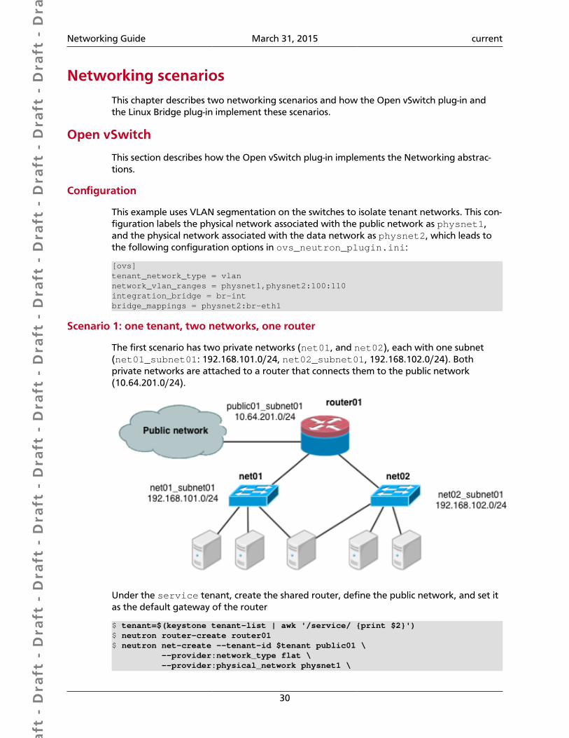
Dra
ft -
Dra
ft -
Dra
ft -
Dra
ft -
Dra
ft -
Dra
ft -
Dra
ft -
Dra
ft -
Dra
ft -
Dra
ft -
Dra
ft -
Dra
ft -
Dra
ft -
Dra
ft -
Dra
ft -
Dra
ft -
Dra
ft -
Dra
ft -
Dra
ft -
Dra
ft -
Dra
ft -
Dra
ft -
Dra
ft -
Dra
ft -
Dra
ft -
Dra
ft -
Dra
ft -
Dra
ft -
Dra
ft -
Dra
ft -
Dra
ft -
Dra
ft -
Dra
ft -
Dra
ft -
Dra
ft -
Networking Guide March 31, 2015 current
30
Networking scenariosThis chapter describes two networking scenarios and how the Open vSwitch plug-in andthe Linux Bridge plug-in implement these scenarios.
Open vSwitch
This section describes how the Open vSwitch plug-in implements the Networking abstrac-tions.
Configuration
This example uses VLAN segmentation on the switches to isolate tenant networks. This con-figuration labels the physical network associated with the public network as physnet1,and the physical network associated with the data network as physnet2, which leads tothe following configuration options in ovs_neutron_plugin.ini:
[ovs]tenant_network_type = vlannetwork_vlan_ranges = physnet1,physnet2:100:110integration_bridge = br-intbridge_mappings = physnet2:br-eth1
Scenario 1: one tenant, two networks, one router
The first scenario has two private networks (net01, and net02), each with one subnet(net01_subnet01: 192.168.101.0/24, net02_subnet01, 192.168.102.0/24). Bothprivate networks are attached to a router that connects them to the public network(10.64.201.0/24).
Under the service tenant, create the shared router, define the public network, and set itas the default gateway of the router
$ tenant=$(keystone tenant-list | awk '/service/ {print $2}')$ neutron router-create router01$ neutron net-create --tenant-id $tenant public01 \ --provider:network_type flat \ --provider:physical_network physnet1 \
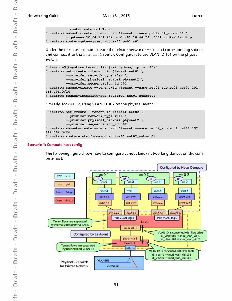
Dra
ft -
Dra
ft -
Dra
ft -
Dra
ft -
Dra
ft -
Dra
ft -
Dra
ft -
Dra
ft -
Dra
ft -
Dra
ft -
Dra
ft -
Dra
ft -
Dra
ft -
Dra
ft -
Dra
ft -
Dra
ft -
Dra
ft -
Dra
ft -
Dra
ft -
Dra
ft -
Dra
ft -
Dra
ft -
Dra
ft -
Dra
ft -
Dra
ft -
Dra
ft -
Dra
ft -
Dra
ft -
Dra
ft -
Dra
ft -
Dra
ft -
Dra
ft -
Dra
ft -
Dra
ft -
Dra
ft -
Networking Guide March 31, 2015 current
31
--router:external True$ neutron subnet-create --tenant-id $tenant --name public01_subnet01 \ --gateway 10.64.201.254 public01 10.64.201.0/24 --disable-dhcp$ neutron router-gateway-set router01 public01
Under the demo user tenant, create the private network net01 and corresponding subnet,and connect it to the router01 router. Configure it to use VLAN ID 101 on the physicalswitch.
$ tenant=$(keystone tenant-list|awk '/demo/ {print $2}'$ neutron net-create --tenant-id $tenant net01 \ --provider:network_type vlan \ --provider:physical_network physnet2 \ --provider:segmentation_id 101$ neutron subnet-create --tenant-id $tenant --name net01_subnet01 net01 192.168.101.0/24$ neutron router-interface-add router01 net01_subnet01
Similarly, for net02, using VLAN ID 102 on the physical switch:
$ neutron net-create --tenant-id $tenant net02 \ --provider:network_type vlan \ --provider:physical_network physnet2 \ --provider:segmentation_id 102$ neutron subnet-create --tenant-id $tenant --name net02_subnet01 net02 192.168.102.0/24$ neutron router-interface-add router01 net02_subnet01
Scenario 1: Compute host config
The following figure shows how to configure various Linux networking devices on the com-pute host:
Dra
ft -
Dra
ft -
Dra
ft -
Dra
ft -
Dra
ft -
Dra
ft -
Dra
ft -
Dra
ft -
Dra
ft -
Dra
ft -
Dra
ft -
Dra
ft -
Dra
ft -
Dra
ft -
Dra
ft -
Dra
ft -
Dra
ft -
Dra
ft -
Dra
ft -
Dra
ft -
Dra
ft -
Dra
ft -
Dra
ft -
Dra
ft -
Dra
ft -
Dra
ft -
Dra
ft -
Dra
ft -
Dra
ft -
Dra
ft -
Dra
ft -
Dra
ft -
Dra
ft -
Dra
ft -
Dra
ft -
Networking Guide March 31, 2015 current
32
Types of network devices
Note
There are four distinct type of virtual networking devices: TAP devices, vethpairs, Linux bridges, and Open vSwitch bridges. For an Ethernet frame to trav-el from eth0 of virtual machine vm01 to the physical network, it must passthrough nine devices inside of the host: TAP vnet0, Linux bridge qbrNNN, vethpair (qvbNNN, qvoNNN), Open vSwitch bridge br-int, veth pair (int-br-eth1, phy-br-eth1), and, finally, the physical network interface cardeth1.
A TAP device, such as vnet0 is how hypervisors such as KVM and Xen implement a virtualnetwork interface card (typically called a VIF or vNIC). An Ethernet frame sent to a TAP de-vice is received by the guest operating system.
A veth pair is a pair of directly connected virtual network interfaces. An Ethernet frame sentto one end of a veth pair is received by the other end of a veth pair. Networking uses vethpairs as virtual patch cables to make connections between virtual bridges.
A Linux bridge behaves like a simple MAC learning switch: you can connect multiple (phys-ical or virtual) network interfaces devices to a Linux bridge. The Linux bridge uses a MACcaching table to record which interface on the bridge is used to communicate with a hoston the link. For any Ethernet frames that come in from one interface attached to thebridge, the host MAC address and port on which the frame was received is recorded in theMAC caching table for a limited time. When the bridge needs to forward a frame, it willcheck to see if the frame's destination MAC address is recorded in the table. If so, the Lin-ux bridge forwards the frame through only that port. If not, the frame is flooded to all net-work ports in the bridge, with the exception of the port where the frame was received.
An Open vSwitch bridge behaves like a virtual switch: network interface devices connect toOpen vSwitch bridge's ports, and the ports can be configured much like a physical switch'sports, including VLAN configurations.
Integration bridge
The br-int Open vSwitch bridge is the integration bridge: all guests running on the com-pute host connect to this bridge. Networking implements isolation across these guests byconfiguring the br-int ports.
Physical connectivity bridge
The br-eth1 bridge provides connectivity to the physical network interface card, eth1. Itconnects to the integration bridge by a veth pair: (int-br-eth1, phy-br-eth1).
VLAN translation
In this example, net01 and net02 have VLAN ids of 1 and 2, respectively. However, thephysical network in our example only supports VLAN IDs in the range 101 through 110.The Open vSwitch agent is responsible for configuring flow rules on br-int and br-eth1to do VLAN translation. When br-eth1 receives a frame marked with VLAN ID 1 on theport associated with phy-br-eth1, it modifies the VLAN ID in the frame to 101. Similar-
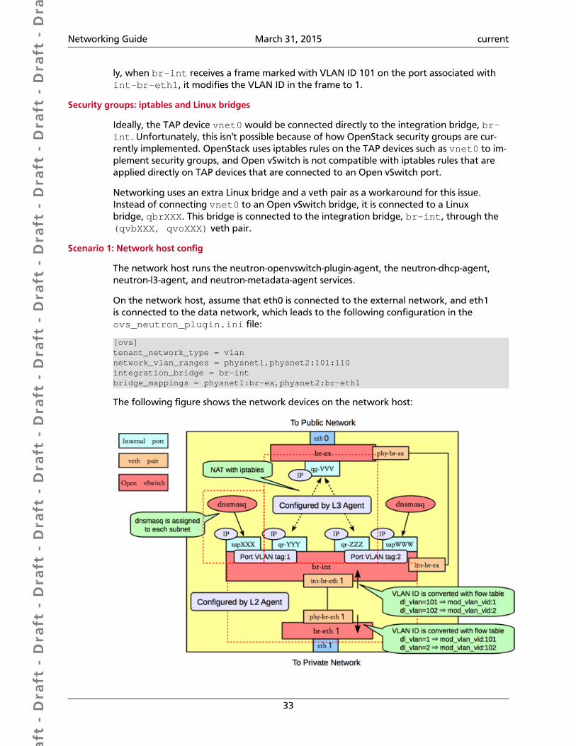
Dra
ft -
Dra
ft -
Dra
ft -
Dra
ft -
Dra
ft -
Dra
ft -
Dra
ft -
Dra
ft -
Dra
ft -
Dra
ft -
Dra
ft -
Dra
ft -
Dra
ft -
Dra
ft -
Dra
ft -
Dra
ft -
Dra
ft -
Dra
ft -
Dra
ft -
Dra
ft -
Dra
ft -
Dra
ft -
Dra
ft -
Dra
ft -
Dra
ft -
Dra
ft -
Dra
ft -
Dra
ft -
Dra
ft -
Dra
ft -
Dra
ft -
Dra
ft -
Dra
ft -
Dra
ft -
Dra
ft -
Networking Guide March 31, 2015 current
33
ly, when br-int receives a frame marked with VLAN ID 101 on the port associated withint-br-eth1, it modifies the VLAN ID in the frame to 1.
Security groups: iptables and Linux bridges
Ideally, the TAP device vnet0 would be connected directly to the integration bridge, br-int. Unfortunately, this isn't possible because of how OpenStack security groups are cur-rently implemented. OpenStack uses iptables rules on the TAP devices such as vnet0 to im-plement security groups, and Open vSwitch is not compatible with iptables rules that areapplied directly on TAP devices that are connected to an Open vSwitch port.
Networking uses an extra Linux bridge and a veth pair as a workaround for this issue.Instead of connecting vnet0 to an Open vSwitch bridge, it is connected to a Linuxbridge, qbrXXX. This bridge is connected to the integration bridge, br-int, through the(qvbXXX, qvoXXX) veth pair.
Scenario 1: Network host config
The network host runs the neutron-openvswitch-plugin-agent, the neutron-dhcp-agent,neutron-l3-agent, and neutron-metadata-agent services.
On the network host, assume that eth0 is connected to the external network, and eth1is connected to the data network, which leads to the following configuration in theovs_neutron_plugin.ini file:
[ovs]tenant_network_type = vlannetwork_vlan_ranges = physnet1,physnet2:101:110integration_bridge = br-intbridge_mappings = physnet1:br-ex,physnet2:br-eth1
The following figure shows the network devices on the network host:
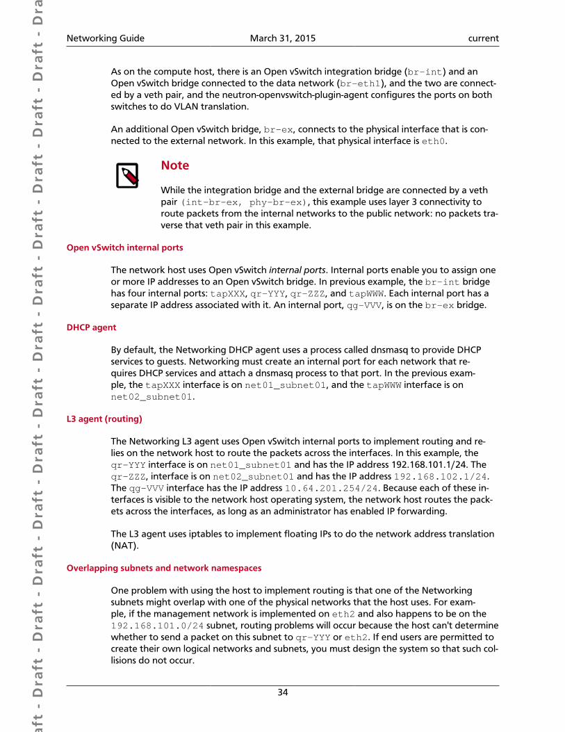
Dra
ft -
Dra
ft -
Dra
ft -
Dra
ft -
Dra
ft -
Dra
ft -
Dra
ft -
Dra
ft -
Dra
ft -
Dra
ft -
Dra
ft -
Dra
ft -
Dra
ft -
Dra
ft -
Dra
ft -
Dra
ft -
Dra
ft -
Dra
ft -
Dra
ft -
Dra
ft -
Dra
ft -
Dra
ft -
Dra
ft -
Dra
ft -
Dra
ft -
Dra
ft -
Dra
ft -
Dra
ft -
Dra
ft -
Dra
ft -
Dra
ft -
Dra
ft -
Dra
ft -
Dra
ft -
Dra
ft -
Networking Guide March 31, 2015 current
34
As on the compute host, there is an Open vSwitch integration bridge (br-int) and anOpen vSwitch bridge connected to the data network (br-eth1), and the two are connect-ed by a veth pair, and the neutron-openvswitch-plugin-agent configures the ports on bothswitches to do VLAN translation.
An additional Open vSwitch bridge, br-ex, connects to the physical interface that is con-nected to the external network. In this example, that physical interface is eth0.
Note
While the integration bridge and the external bridge are connected by a vethpair (int-br-ex, phy-br-ex), this example uses layer 3 connectivity toroute packets from the internal networks to the public network: no packets tra-verse that veth pair in this example.
Open vSwitch internal ports
The network host uses Open vSwitch internal ports. Internal ports enable you to assign oneor more IP addresses to an Open vSwitch bridge. In previous example, the br-int bridgehas four internal ports: tapXXX, qr-YYY, qr-ZZZ, and tapWWW. Each internal port has aseparate IP address associated with it. An internal port, qg-VVV, is on the br-ex bridge.
DHCP agent
By default, the Networking DHCP agent uses a process called dnsmasq to provide DHCPservices to guests. Networking must create an internal port for each network that re-quires DHCP services and attach a dnsmasq process to that port. In the previous exam-ple, the tapXXX interface is on net01_subnet01, and the tapWWW interface is onnet02_subnet01.
L3 agent (routing)
The Networking L3 agent uses Open vSwitch internal ports to implement routing and re-lies on the network host to route the packets across the interfaces. In this example, theqr-YYY interface is on net01_subnet01 and has the IP address 192.168.101.1/24. Theqr-ZZZ, interface is on net02_subnet01 and has the IP address 192.168.102.1/24.The qg-VVV interface has the IP address 10.64.201.254/24. Because each of these in-terfaces is visible to the network host operating system, the network host routes the pack-ets across the interfaces, as long as an administrator has enabled IP forwarding.
The L3 agent uses iptables to implement floating IPs to do the network address translation(NAT).
Overlapping subnets and network namespaces
One problem with using the host to implement routing is that one of the Networkingsubnets might overlap with one of the physical networks that the host uses. For exam-ple, if the management network is implemented on eth2 and also happens to be on the192.168.101.0/24 subnet, routing problems will occur because the host can't determinewhether to send a packet on this subnet to qr-YYY or eth2. If end users are permitted tocreate their own logical networks and subnets, you must design the system so that such col-lisions do not occur.
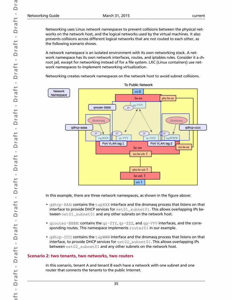
Dra
ft -
Dra
ft -
Dra
ft -
Dra
ft -
Dra
ft -
Dra
ft -
Dra
ft -
Dra
ft -
Dra
ft -
Dra
ft -
Dra
ft -
Dra
ft -
Dra
ft -
Dra
ft -
Dra
ft -
Dra
ft -
Dra
ft -
Dra
ft -
Dra
ft -
Dra
ft -
Dra
ft -
Dra
ft -
Dra
ft -
Dra
ft -
Dra
ft -
Dra
ft -
Dra
ft -
Dra
ft -
Dra
ft -
Dra
ft -
Dra
ft -
Dra
ft -
Dra
ft -
Dra
ft -
Dra
ft -
Networking Guide March 31, 2015 current
35
Networking uses Linux network namespaces to prevent collisions between the physical net-works on the network host, and the logical networks used by the virtual machines. It alsoprevents collisions across different logical networks that are not routed to each other, asthe following scenario shows.
A network namespace is an isolated environment with its own networking stack. A net-work namespace has its own network interfaces, routes, and iptables rules. Consider it a ch-root jail, except for networking instead of for a file system. LXC (Linux containers) use net-work namespaces to implement networking virtualization.
Networking creates network namespaces on the network host to avoid subnet collisions.
In this example, there are three network namespaces, as shown in the figure above:
• qdhcp-AAA: contains the tapXXX interface and the dnsmasq process that listens on thatinterface to provide DHCP services for net01_subnet01. This allows overlapping IPs be-tween net01_subnet01 and any other subnets on the network host.
• qrouter-BBBB: contains the qr-YYY, qr-ZZZ, and qg-VVV interfaces, and the corre-sponding routes. This namespace implements router01 in our example.
• qdhcp-CCC: contains the tapWWW interface and the dnsmasq process that listens on thatinterface, to provide DHCP services for net02_subnet01. This allows overlapping IPsbetween net02_subnet01 and any other subnets on the network host.
Scenario 2: two tenants, two networks, two routers
In this scenario, tenant A and tenant B each have a network with one subnet and onerouter that connects the tenants to the public Internet.

Dra
ft -
Dra
ft -
Dra
ft -
Dra
ft -
Dra
ft -
Dra
ft -
Dra
ft -
Dra
ft -
Dra
ft -
Dra
ft -
Dra
ft -
Dra
ft -
Dra
ft -
Dra
ft -
Dra
ft -
Dra
ft -
Dra
ft -
Dra
ft -
Dra
ft -
Dra
ft -
Dra
ft -
Dra
ft -
Dra
ft -
Dra
ft -
Dra
ft -
Dra
ft -
Dra
ft -
Dra
ft -
Dra
ft -
Dra
ft -
Dra
ft -
Dra
ft -
Dra
ft -
Dra
ft -
Dra
ft -
Networking Guide March 31, 2015 current
36
Under the service tenant, define the public network:
$ tenant=$(keystone tenant-list | awk '/service/ {print $2}')$ neutron net-create --tenant-id $tenant public01 \ --provider:network_type flat \ --provider:physical_network physnet1 \ --router:external True$ neutron subnet-create --tenant-id $tenant --name public01_subnet01 \ --gateway 10.64.201.254 public01 10.64.201.0/24 --disable-dhcp
Under the tenantA user tenant, create the tenant router and set its gateway for the pub-lic network.
$ tenant=$(keystone tenant-list|awk '/tenantA/ {print $2}')$ neutron router-create --tenant-id $tenant router01$ neutron router-gateway-set router01 public01
Then, define private network net01 using VLAN ID 101 on the physical switch, along withits subnet, and connect it to the router.
$ neutron net-create --tenant-id $tenant net01 \ --provider:network_type vlan \ --provider:physical_network physnet2 \ --provider:segmentation_id 101$ neutron subnet-create --tenant-id $tenant --name net01_subnet01 net01 192.168.101.0/24$ neutron router-interface-add router01 net01_subnet01
Similarly, for tenantB, create a router and another network, using VLAN ID 102 on thephysical switch:
$ tenant=$(keystone tenant-list|awk '/tenantB/ {print $2}')
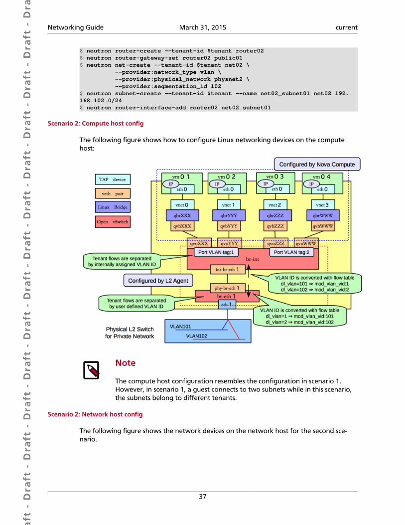
Dra
ft -
Dra
ft -
Dra
ft -
Dra
ft -
Dra
ft -
Dra
ft -
Dra
ft -
Dra
ft -
Dra
ft -
Dra
ft -
Dra
ft -
Dra
ft -
Dra
ft -
Dra
ft -
Dra
ft -
Dra
ft -
Dra
ft -
Dra
ft -
Dra
ft -
Dra
ft -
Dra
ft -
Dra
ft -
Dra
ft -
Dra
ft -
Dra
ft -
Dra
ft -
Dra
ft -
Dra
ft -
Dra
ft -
Dra
ft -
Dra
ft -
Dra
ft -
Dra
ft -
Dra
ft -
Dra
ft -
Networking Guide March 31, 2015 current
37
$ neutron router-create --tenant-id $tenant router02$ neutron router-gateway-set router02 public01$ neutron net-create --tenant-id $tenant net02 \ --provider:network_type vlan \ --provider:physical_network physnet2 \ --provider:segmentation_id 102$ neutron subnet-create --tenant-id $tenant --name net02_subnet01 net02 192.168.102.0/24$ neutron router-interface-add router02 net02_subnet01
Scenario 2: Compute host config
The following figure shows how to configure Linux networking devices on the computehost:
Note
The compute host configuration resembles the configuration in scenario 1.However, in scenario 1, a guest connects to two subnets while in this scenario,the subnets belong to different tenants.
Scenario 2: Network host config
The following figure shows the network devices on the network host for the second sce-nario.
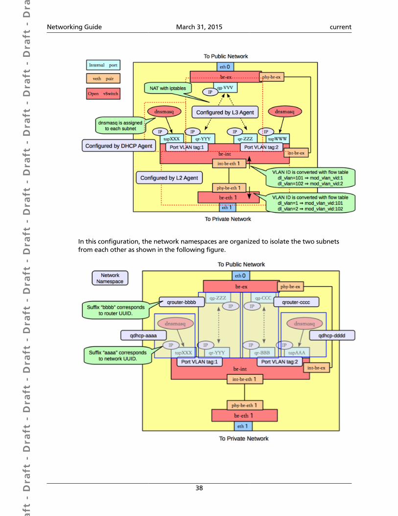
Dra
ft -
Dra
ft -
Dra
ft -
Dra
ft -
Dra
ft -
Dra
ft -
Dra
ft -
Dra
ft -
Dra
ft -
Dra
ft -
Dra
ft -
Dra
ft -
Dra
ft -
Dra
ft -
Dra
ft -
Dra
ft -
Dra
ft -
Dra
ft -
Dra
ft -
Dra
ft -
Dra
ft -
Dra
ft -
Dra
ft -
Dra
ft -
Dra
ft -
Dra
ft -
Dra
ft -
Dra
ft -
Dra
ft -
Dra
ft -
Dra
ft -
Dra
ft -
Dra
ft -
Dra
ft -
Dra
ft -
Networking Guide March 31, 2015 current
38
In this configuration, the network namespaces are organized to isolate the two subnetsfrom each other as shown in the following figure.

Dra
ft -
Dra
ft -
Dra
ft -
Dra
ft -
Dra
ft -
Dra
ft -
Dra
ft -
Dra
ft -
Dra
ft -
Dra
ft -
Dra
ft -
Dra
ft -
Dra
ft -
Dra
ft -
Dra
ft -
Dra
ft -
Dra
ft -
Dra
ft -
Dra
ft -
Dra
ft -
Dra
ft -
Dra
ft -
Dra
ft -
Dra
ft -
Dra
ft -
Dra
ft -
Dra
ft -
Dra
ft -
Dra
ft -
Dra
ft -
Dra
ft -
Dra
ft -
Dra
ft -
Dra
ft -
Dra
ft -
Networking Guide March 31, 2015 current
39
In this scenario, there are four network namespaces (qhdcp-AAA, qrouter-BBBB,qrouter-CCCC, and qhdcp-DDDD), instead of three. Because there is no connectivity be-tween the two networks, each router is implemented by a separate namespace.
Configure Open vSwitch tunneling
Tunneling encapsulates network traffic between physical Networking hosts and allowsVLANs to span multiple physical hosts. Instances communicate as if they share the same lay-er 2 network. Open vSwitch supports tunneling with the VXLAN and GRE encapsulationprotocols.
Figure 5.1. Example VXLAN tunnel
This diagram shows two instances running on separate hosts connected by a VXLAN tun-nel. The required physical and virtual components are also illustrated. The following pro-cedure creates a VXLAN or GRE tunnel between two Open vSwitches running on separateNetworking hosts:
Example tunnel configuration
1. Create a virtual bridge named OVS-BR0 on each participating host:
ovs-vsctl add-br OVS-BR0
2. Create a tunnel to link the OVS-BR0 virtual bridges. Run the ovs-vsctl command onHOST1 to create the tunnel and link it to the bridge on HOST2:
GRE tunnel command:
ovs-vsctl add-port OVS-BR0 gre1 -- set Interface gre1 type=gre options:remote_ip=192.168.1.11
VXLAN tunnel command:
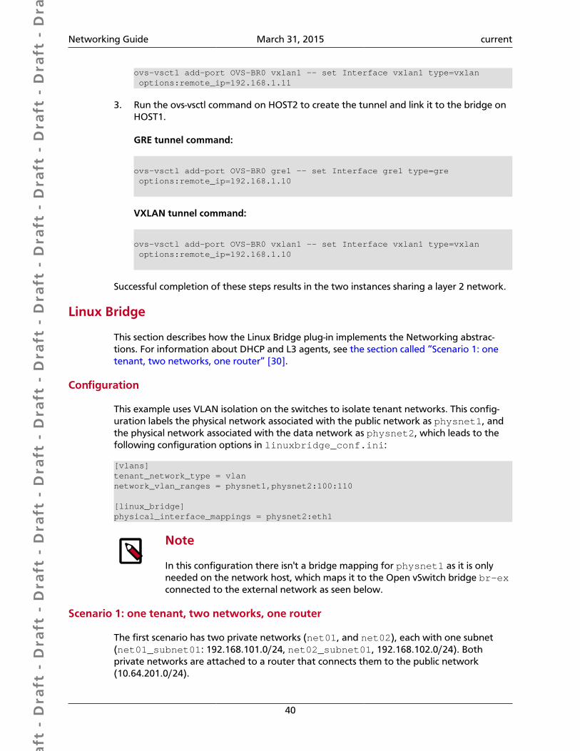
Dra
ft -
Dra
ft -
Dra
ft -
Dra
ft -
Dra
ft -
Dra
ft -
Dra
ft -
Dra
ft -
Dra
ft -
Dra
ft -
Dra
ft -
Dra
ft -
Dra
ft -
Dra
ft -
Dra
ft -
Dra
ft -
Dra
ft -
Dra
ft -
Dra
ft -
Dra
ft -
Dra
ft -
Dra
ft -
Dra
ft -
Dra
ft -
Dra
ft -
Dra
ft -
Dra
ft -
Dra
ft -
Dra
ft -
Dra
ft -
Dra
ft -
Dra
ft -
Dra
ft -
Dra
ft -
Dra
ft -
Networking Guide March 31, 2015 current
40
ovs-vsctl add-port OVS-BR0 vxlan1 -- set Interface vxlan1 type=vxlan options:remote_ip=192.168.1.11
3. Run the ovs-vsctl command on HOST2 to create the tunnel and link it to the bridge onHOST1.
GRE tunnel command:
ovs-vsctl add-port OVS-BR0 gre1 -- set Interface gre1 type=gre options:remote_ip=192.168.1.10
VXLAN tunnel command:
ovs-vsctl add-port OVS-BR0 vxlan1 -- set Interface vxlan1 type=vxlan options:remote_ip=192.168.1.10
Successful completion of these steps results in the two instances sharing a layer 2 network.
Linux Bridge
This section describes how the Linux Bridge plug-in implements the Networking abstrac-tions. For information about DHCP and L3 agents, see the section called “Scenario 1: onetenant, two networks, one router” [30].
Configuration
This example uses VLAN isolation on the switches to isolate tenant networks. This config-uration labels the physical network associated with the public network as physnet1, andthe physical network associated with the data network as physnet2, which leads to thefollowing configuration options in linuxbridge_conf.ini:
[vlans]tenant_network_type = vlannetwork_vlan_ranges = physnet1,physnet2:100:110
[linux_bridge]physical_interface_mappings = physnet2:eth1
Note
In this configuration there isn't a bridge mapping for physnet1 as it is onlyneeded on the network host, which maps it to the Open vSwitch bridge br-exconnected to the external network as seen below.
Scenario 1: one tenant, two networks, one router
The first scenario has two private networks (net01, and net02), each with one subnet(net01_subnet01: 192.168.101.0/24, net02_subnet01, 192.168.102.0/24). Bothprivate networks are attached to a router that connects them to the public network(10.64.201.0/24).
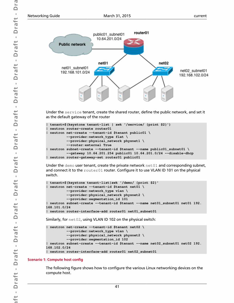
Dra
ft -
Dra
ft -
Dra
ft -
Dra
ft -
Dra
ft -
Dra
ft -
Dra
ft -
Dra
ft -
Dra
ft -
Dra
ft -
Dra
ft -
Dra
ft -
Dra
ft -
Dra
ft -
Dra
ft -
Dra
ft -
Dra
ft -
Dra
ft -
Dra
ft -
Dra
ft -
Dra
ft -
Dra
ft -
Dra
ft -
Dra
ft -
Dra
ft -
Dra
ft -
Dra
ft -
Dra
ft -
Dra
ft -
Dra
ft -
Dra
ft -
Dra
ft -
Dra
ft -
Dra
ft -
Dra
ft -
Networking Guide March 31, 2015 current
41
Under the service tenant, create the shared router, define the public network, and set itas the default gateway of the router
$ tenant=$(keystone tenant-list | awk '/service/ {print $2}')$ neutron router-create router01$ neutron net-create --tenant-id $tenant public01 \ --provider:network_type flat \ --provider:physical_network physnet1 \ --router:external True$ neutron subnet-create --tenant-id $tenant --name public01_subnet01 \ --gateway 10.64.201.254 public01 10.64.201.0/24 --disable-dhcp$ neutron router-gateway-set router01 public01
Under the demo user tenant, create the private network net01 and corresponding subnet,and connect it to the router01 router. Configure it to use VLAN ID 101 on the physicalswitch.
$ tenant=$(keystone tenant-list|awk '/demo/ {print $2}'$ neutron net-create --tenant-id $tenant net01 \ --provider:network_type vlan \ --provider:physical_network physnet2 \ --provider:segmentation_id 101$ neutron subnet-create --tenant-id $tenant --name net01_subnet01 net01 192.168.101.0/24$ neutron router-interface-add router01 net01_subnet01
Similarly, for net02, using VLAN ID 102 on the physical switch:
$ neutron net-create --tenant-id $tenant net02 \ --provider:network_type vlan \ --provider:physical_network physnet2 \ --provider:segmentation_id 102$ neutron subnet-create --tenant-id $tenant --name net02_subnet01 net02 192.168.102.0/24$ neutron router-interface-add router01 net02_subnet01
Scenario 1: Compute host config
The following figure shows how to configure the various Linux networking devices on thecompute host.
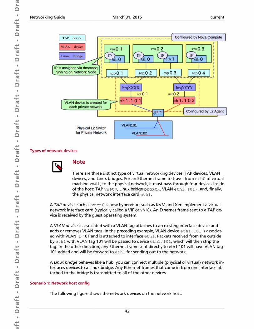
Dra
ft -
Dra
ft -
Dra
ft -
Dra
ft -
Dra
ft -
Dra
ft -
Dra
ft -
Dra
ft -
Dra
ft -
Dra
ft -
Dra
ft -
Dra
ft -
Dra
ft -
Dra
ft -
Dra
ft -
Dra
ft -
Dra
ft -
Dra
ft -
Dra
ft -
Dra
ft -
Dra
ft -
Dra
ft -
Dra
ft -
Dra
ft -
Dra
ft -
Dra
ft -
Dra
ft -
Dra
ft -
Dra
ft -
Dra
ft -
Dra
ft -
Dra
ft -
Dra
ft -
Dra
ft -
Dra
ft -
Networking Guide March 31, 2015 current
42
Types of network devices
Note
There are three distinct type of virtual networking devices: TAP devices, VLANdevices, and Linux bridges. For an Ethernet frame to travel from eth0 of virtualmachine vm01, to the physical network, it must pass through four devices insideof the host: TAP vnet0, Linux bridge brqXXX, VLAN eth1.101), and, finally,the physical network interface card eth1.
A TAP device, such as vnet0 is how hypervisors such as KVM and Xen implement a virtualnetwork interface card (typically called a VIF or vNIC). An Ethernet frame sent to a TAP de-vice is received by the guest operating system.
A VLAN device is associated with a VLAN tag attaches to an existing interface device andadds or removes VLAN tags. In the preceding example, VLAN device eth1.101 is associat-ed with VLAN ID 101 and is attached to interface eth1. Packets received from the outsideby eth1 with VLAN tag 101 will be passed to device eth1.101, which will then strip thetag. In the other direction, any Ethernet frame sent directly to eth1.101 will have VLAN tag101 added and will be forward to eth1 for sending out to the network.
A Linux bridge behaves like a hub: you can connect multiple (physical or virtual) network in-terfaces devices to a Linux bridge. Any Ethernet frames that come in from one interface at-tached to the bridge is transmitted to all of the other devices.
Scenario 1: Network host config
The following figure shows the network devices on the network host.
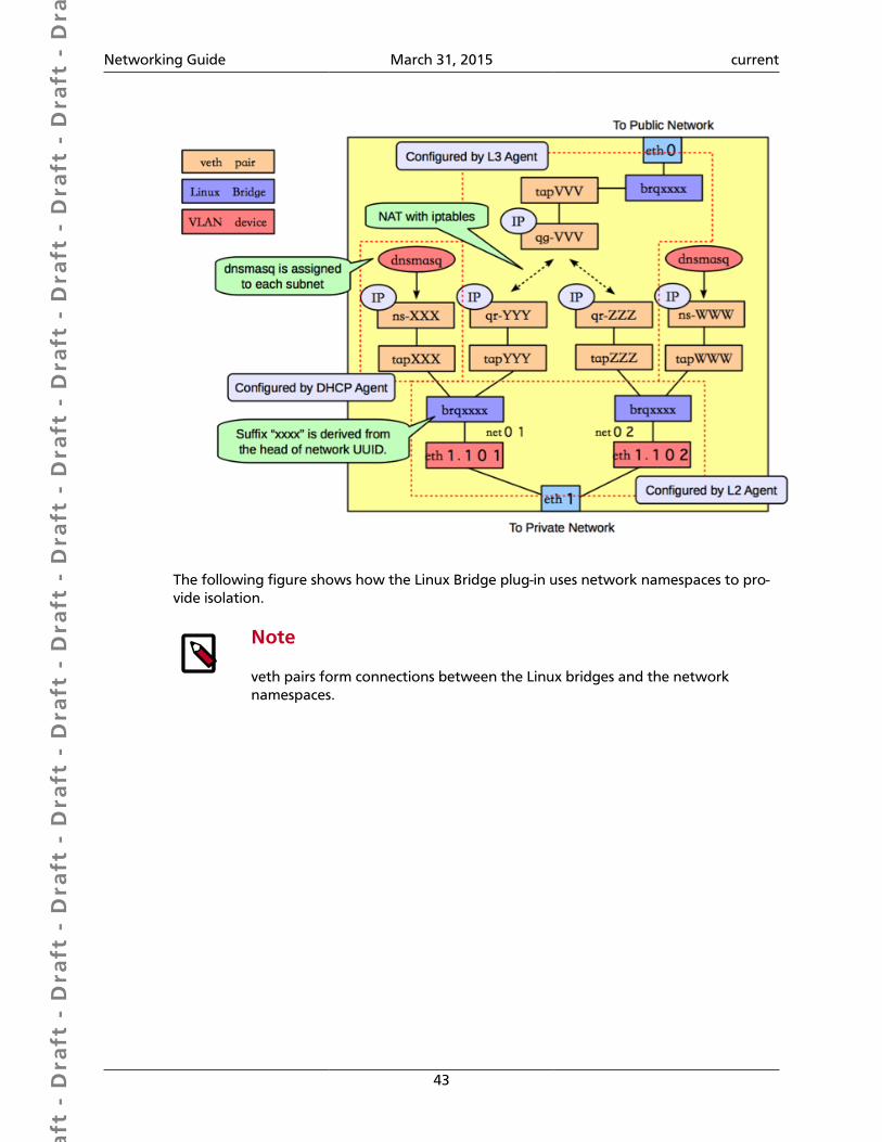
Dra
ft -
Dra
ft -
Dra
ft -
Dra
ft -
Dra
ft -
Dra
ft -
Dra
ft -
Dra
ft -
Dra
ft -
Dra
ft -
Dra
ft -
Dra
ft -
Dra
ft -
Dra
ft -
Dra
ft -
Dra
ft -
Dra
ft -
Dra
ft -
Dra
ft -
Dra
ft -
Dra
ft -
Dra
ft -
Dra
ft -
Dra
ft -
Dra
ft -
Dra
ft -
Dra
ft -
Dra
ft -
Dra
ft -
Dra
ft -
Dra
ft -
Dra
ft -
Dra
ft -
Dra
ft -
Dra
ft -
Networking Guide March 31, 2015 current
43
The following figure shows how the Linux Bridge plug-in uses network namespaces to pro-vide isolation.
Note
veth pairs form connections between the Linux bridges and the networknamespaces.
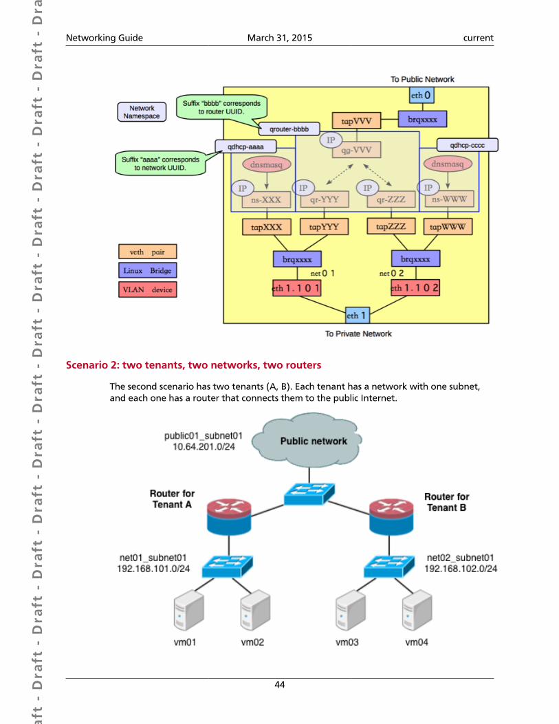
Dra
ft -
Dra
ft -
Dra
ft -
Dra
ft -
Dra
ft -
Dra
ft -
Dra
ft -
Dra
ft -
Dra
ft -
Dra
ft -
Dra
ft -
Dra
ft -
Dra
ft -
Dra
ft -
Dra
ft -
Dra
ft -
Dra
ft -
Dra
ft -
Dra
ft -
Dra
ft -
Dra
ft -
Dra
ft -
Dra
ft -
Dra
ft -
Dra
ft -
Dra
ft -
Dra
ft -
Dra
ft -
Dra
ft -
Dra
ft -
Dra
ft -
Dra
ft -
Dra
ft -
Dra
ft -
Dra
ft -
Networking Guide March 31, 2015 current
44
Scenario 2: two tenants, two networks, two routers
The second scenario has two tenants (A, B). Each tenant has a network with one subnet,and each one has a router that connects them to the public Internet.
Dra
ft -
Dra
ft -
Dra
ft -
Dra
ft -
Dra
ft -
Dra
ft -
Dra
ft -
Dra
ft -
Dra
ft -
Dra
ft -
Dra
ft -
Dra
ft -
Dra
ft -
Dra
ft -
Dra
ft -
Dra
ft -
Dra
ft -
Dra
ft -
Dra
ft -
Dra
ft -
Dra
ft -
Dra
ft -
Dra
ft -
Dra
ft -
Dra
ft -
Dra
ft -
Dra
ft -
Dra
ft -
Dra
ft -
Dra
ft -
Dra
ft -
Dra
ft -
Dra
ft -
Dra
ft -
Dra
ft -
Networking Guide March 31, 2015 current
45
Under the service tenant, define the public network:
$ tenant=$(keystone tenant-list | awk '/service/ {print $2}')$ neutron net-create --tenant-id $tenant public01 \ --provider:network_type flat \ --provider:physical_network physnet1 \ --router:external True$ neutron subnet-create --tenant-id $tenant --name public01_subnet01 \ --gateway 10.64.201.254 public01 10.64.201.0/24 --disable-dhcp
Under the tenantA user tenant, create the tenant router and set its gateway for the pub-lic network.
$ tenant=$(keystone tenant-list|awk '/tenantA/ {print $2}')$ neutron router-create --tenant-id $tenant router01$ neutron router-gateway-set router01 public01
Then, define private network net01 using VLAN ID 102 on the physical switch, along withits subnet, and connect it to the router.
$ neutron net-create --tenant-id $tenant net01 \ --provider:network_type vlan \ --provider:physical_network physnet2 \ --provider:segmentation_id 101$ neutron subnet-create --tenant-id $tenant --name net01_subnet01 net01 192.168.101.0/24$ neutron router-interface-add router01 net01_subnet01
Similarly, for tenantB, create a router and another network, using VLAN ID 102 on thephysical switch:
$ tenant=$(keystone tenant-list|awk '/tenantB/ {print $2}')$ neutron router-create --tenant-id $tenant router02$ neutron router-gateway-set router02 public01$ neutron net-create --tenant-id $tenant net02 \ --provider:network_type vlan \ --provider:physical_network physnet2 \ --provider:segmentation_id 102$ neutron subnet-create --tenant-id $tenant --name net02_subnet01 net01 192.168.101.0/24$ neutron router-interface-add router02 net02_subnet01
Scenario 2: Compute host config
The following figure shows how the various Linux networking devices would be configuredon the compute host under this scenario.
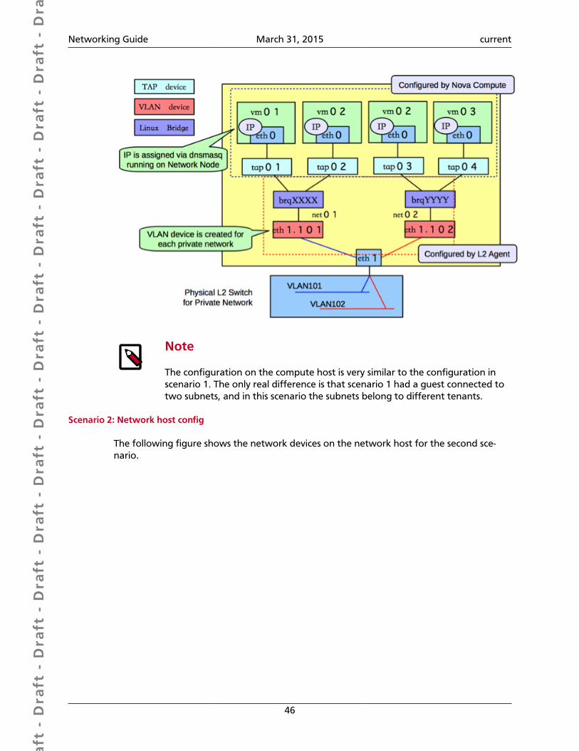
Dra
ft -
Dra
ft -
Dra
ft -
Dra
ft -
Dra
ft -
Dra
ft -
Dra
ft -
Dra
ft -
Dra
ft -
Dra
ft -
Dra
ft -
Dra
ft -
Dra
ft -
Dra
ft -
Dra
ft -
Dra
ft -
Dra
ft -
Dra
ft -
Dra
ft -
Dra
ft -
Dra
ft -
Dra
ft -
Dra
ft -
Dra
ft -
Dra
ft -
Dra
ft -
Dra
ft -
Dra
ft -
Dra
ft -
Dra
ft -
Dra
ft -
Dra
ft -
Dra
ft -
Dra
ft -
Dra
ft -
Networking Guide March 31, 2015 current
46
Note
The configuration on the compute host is very similar to the configuration inscenario 1. The only real difference is that scenario 1 had a guest connected totwo subnets, and in this scenario the subnets belong to different tenants.
Scenario 2: Network host config
The following figure shows the network devices on the network host for the second sce-nario.
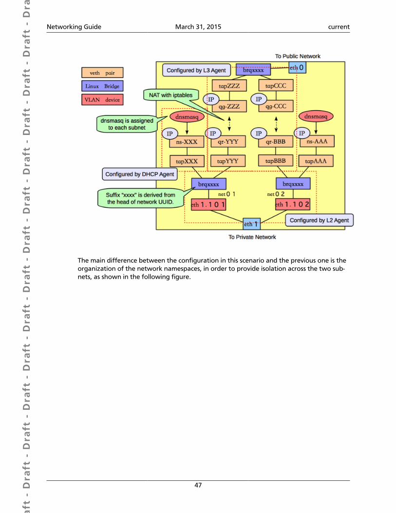
Dra
ft -
Dra
ft -
Dra
ft -
Dra
ft -
Dra
ft -
Dra
ft -
Dra
ft -
Dra
ft -
Dra
ft -
Dra
ft -
Dra
ft -
Dra
ft -
Dra
ft -
Dra
ft -
Dra
ft -
Dra
ft -
Dra
ft -
Dra
ft -
Dra
ft -
Dra
ft -
Dra
ft -
Dra
ft -
Dra
ft -
Dra
ft -
Dra
ft -
Dra
ft -
Dra
ft -
Dra
ft -
Dra
ft -
Dra
ft -
Dra
ft -
Dra
ft -
Dra
ft -
Dra
ft -
Dra
ft -
Networking Guide March 31, 2015 current
47
The main difference between the configuration in this scenario and the previous one is theorganization of the network namespaces, in order to provide isolation across the two sub-nets, as shown in the following figure.
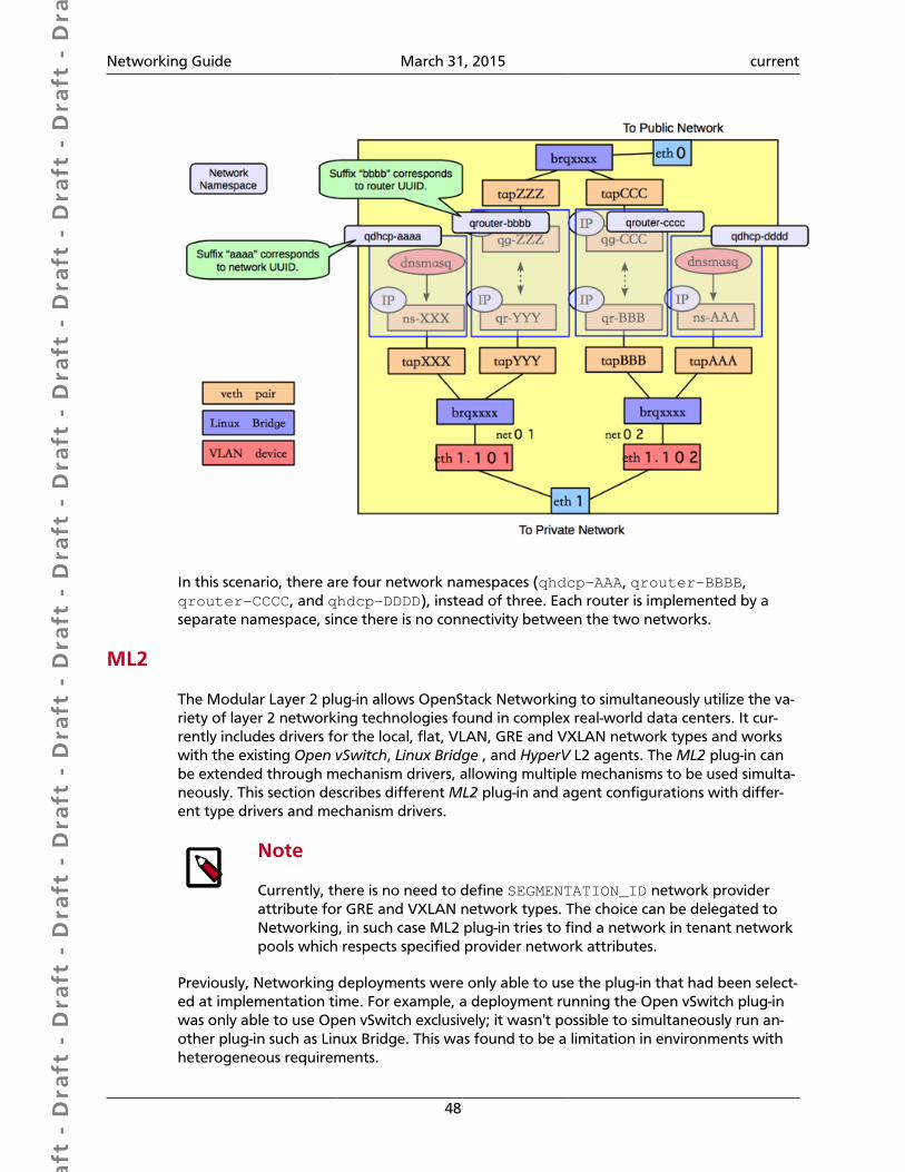
Dra
ft -
Dra
ft -
Dra
ft -
Dra
ft -
Dra
ft -
Dra
ft -
Dra
ft -
Dra
ft -
Dra
ft -
Dra
ft -
Dra
ft -
Dra
ft -
Dra
ft -
Dra
ft -
Dra
ft -
Dra
ft -
Dra
ft -
Dra
ft -
Dra
ft -
Dra
ft -
Dra
ft -
Dra
ft -
Dra
ft -
Dra
ft -
Dra
ft -
Dra
ft -
Dra
ft -
Dra
ft -
Dra
ft -
Dra
ft -
Dra
ft -
Dra
ft -
Dra
ft -
Dra
ft -
Dra
ft -
Networking Guide March 31, 2015 current
48
In this scenario, there are four network namespaces (qhdcp-AAA, qrouter-BBBB,qrouter-CCCC, and qhdcp-DDDD), instead of three. Each router is implemented by aseparate namespace, since there is no connectivity between the two networks.
ML2
The Modular Layer 2 plug-in allows OpenStack Networking to simultaneously utilize the va-riety of layer 2 networking technologies found in complex real-world data centers. It cur-rently includes drivers for the local, flat, VLAN, GRE and VXLAN network types and workswith the existing Open vSwitch, Linux Bridge , and HyperV L2 agents. The ML2 plug-in canbe extended through mechanism drivers, allowing multiple mechanisms to be used simulta-neously. This section describes different ML2 plug-in and agent configurations with differ-ent type drivers and mechanism drivers.
Note
Currently, there is no need to define SEGMENTATION_ID network providerattribute for GRE and VXLAN network types. The choice can be delegated toNetworking, in such case ML2 plug-in tries to find a network in tenant networkpools which respects specified provider network attributes.
Previously, Networking deployments were only able to use the plug-in that had been select-ed at implementation time. For example, a deployment running the Open vSwitch plug-inwas only able to use Open vSwitch exclusively; it wasn't possible to simultaneously run an-other plug-in such as Linux Bridge. This was found to be a limitation in environments withheterogeneous requirements.
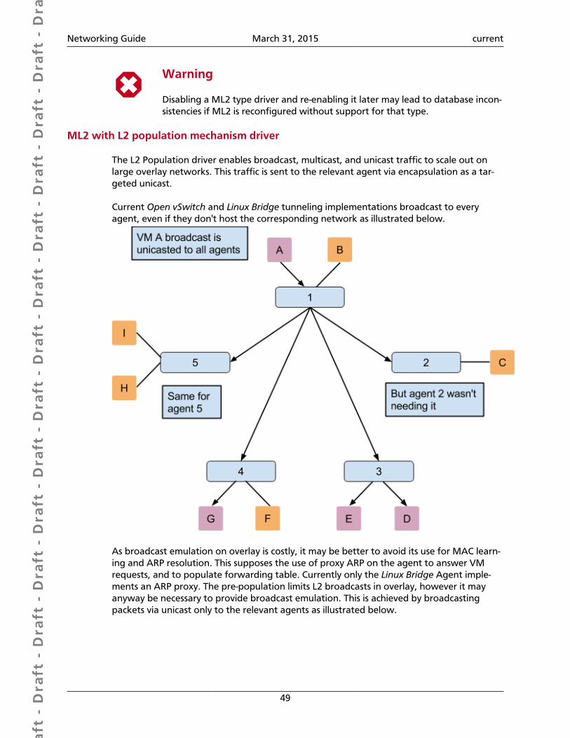
Dra
ft -
Dra
ft -
Dra
ft -
Dra
ft -
Dra
ft -
Dra
ft -
Dra
ft -
Dra
ft -
Dra
ft -
Dra
ft -
Dra
ft -
Dra
ft -
Dra
ft -
Dra
ft -
Dra
ft -
Dra
ft -
Dra
ft -
Dra
ft -
Dra
ft -
Dra
ft -
Dra
ft -
Dra
ft -
Dra
ft -
Dra
ft -
Dra
ft -
Dra
ft -
Dra
ft -
Dra
ft -
Dra
ft -
Dra
ft -
Dra
ft -
Dra
ft -
Dra
ft -
Dra
ft -
Dra
ft -
Networking Guide March 31, 2015 current
49
Warning
Disabling a ML2 type driver and re-enabling it later may lead to database incon-sistencies if ML2 is reconfigured without support for that type.
ML2 with L2 population mechanism driver
The L2 Population driver enables broadcast, multicast, and unicast traffic to scale out onlarge overlay networks. This traffic is sent to the relevant agent via encapsulation as a tar-geted unicast.
Current Open vSwitch and Linux Bridge tunneling implementations broadcast to everyagent, even if they don't host the corresponding network as illustrated below.
As broadcast emulation on overlay is costly, it may be better to avoid its use for MAC learn-ing and ARP resolution. This supposes the use of proxy ARP on the agent to answer VMrequests, and to populate forwarding table. Currently only the Linux Bridge Agent imple-ments an ARP proxy. The pre-population limits L2 broadcasts in overlay, however it mayanyway be necessary to provide broadcast emulation. This is achieved by broadcastingpackets via unicast only to the relevant agents as illustrated below.
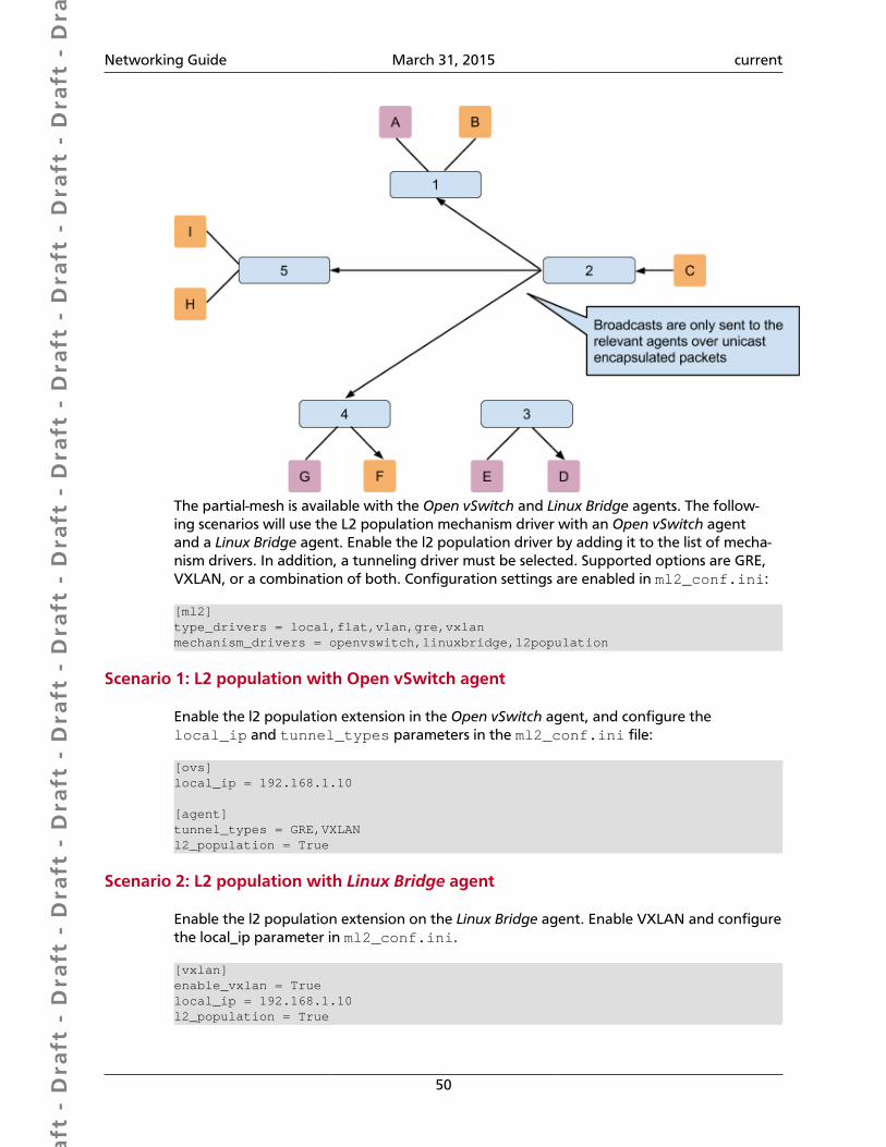
Dra
ft -
Dra
ft -
Dra
ft -
Dra
ft -
Dra
ft -
Dra
ft -
Dra
ft -
Dra
ft -
Dra
ft -
Dra
ft -
Dra
ft -
Dra
ft -
Dra
ft -
Dra
ft -
Dra
ft -
Dra
ft -
Dra
ft -
Dra
ft -
Dra
ft -
Dra
ft -
Dra
ft -
Dra
ft -
Dra
ft -
Dra
ft -
Dra
ft -
Dra
ft -
Dra
ft -
Dra
ft -
Dra
ft -
Dra
ft -
Dra
ft -
Dra
ft -
Dra
ft -
Dra
ft -
Dra
ft -
Networking Guide March 31, 2015 current
50
The partial-mesh is available with the Open vSwitch and Linux Bridge agents. The follow-ing scenarios will use the L2 population mechanism driver with an Open vSwitch agentand a Linux Bridge agent. Enable the l2 population driver by adding it to the list of mecha-nism drivers. In addition, a tunneling driver must be selected. Supported options are GRE,VXLAN, or a combination of both. Configuration settings are enabled in ml2_conf.ini:
[ml2]type_drivers = local,flat,vlan,gre,vxlanmechanism_drivers = openvswitch,linuxbridge,l2population
Scenario 1: L2 population with Open vSwitch agent
Enable the l2 population extension in the Open vSwitch agent, and configure thelocal_ip and tunnel_types parameters in the ml2_conf.ini file:
[ovs]local_ip = 192.168.1.10
[agent]tunnel_types = GRE,VXLANl2_population = True
Scenario 2: L2 population with Linux Bridge agent
Enable the l2 population extension on the Linux Bridge agent. Enable VXLAN and configurethe local_ip parameter in ml2_conf.ini.
[vxlan]enable_vxlan = Truelocal_ip = 192.168.1.10l2_population = True
Dra
ft -
Dra
ft -
Dra
ft -
Dra
ft -
Dra
ft -
Dra
ft -
Dra
ft -
Dra
ft -
Dra
ft -
Dra
ft -
Dra
ft -
Dra
ft -
Dra
ft -
Dra
ft -
Dra
ft -
Dra
ft -
Dra
ft -
Dra
ft -
Dra
ft -
Dra
ft -
Dra
ft -
Dra
ft -
Dra
ft -
Dra
ft -
Dra
ft -
Dra
ft -
Dra
ft -
Dra
ft -
Dra
ft -
Dra
ft -
Dra
ft -
Dra
ft -
Dra
ft -
Dra
ft -
Dra
ft -
Networking Guide March 31, 2015 current
51
Enable security group API
The ML2 plug-in can concurrently support different L2 agents (or other mecha-nisms) with different configuration files, so each L2 agent configuration file (suchas ovs_neutron_plugin.ini or linuxbridge_conf.ini) should containthe appropriate firewall_driver value for that agent in addition to settingenable_security_group to True (which is the default).
The firewall_driver value in the API server's ml2_conf.ini file does not matter.
To disable the securitygroup API, edit the ml2_conf.ini file on the API server, andovs_neutron_plugin.ini, linuxbridge_conf.ini or other L2 agent configurationfiles on the agent servers :
[securitygroup]enable_security_group = Falsefirewall_driver = neutron.agent.firewall.NoopFirewallDriver
Dra
ft -
Dra
ft -
Dra
ft -
Dra
ft -
Dra
ft -
Dra
ft -
Dra
ft -
Dra
ft -
Dra
ft -
Dra
ft -
Dra
ft -
Dra
ft -
Dra
ft -
Dra
ft -
Dra
ft -
Dra
ft -
Dra
ft -
Dra
ft -
Dra
ft -
Dra
ft -
Dra
ft -
Dra
ft -
Dra
ft -
Dra
ft -
Dra
ft -
Dra
ft -
Dra
ft -
Dra
ft -
Dra
ft -
Dra
ft -
Dra
ft -
Dra
ft -
Dra
ft -
Dra
ft -
Dra
ft -
Networking Guide March 31, 2015 current
52
6. Scalability and high availability
Table of ContentsDHCP Agents ................................................................................................................ 52L3 Agents ...................................................................................................................... 52Distributed Virtual Router (DVR) ................................................................................... 52
Bacon ipsum dolor sit amet biltong meatloaf andouille, turducken bresaola pork belly beefribs ham hock capicola tail prosciutto landjaeger meatball pork loin. Swine turkey jowl,porchetta doner boudin meatloaf. Shoulder capicola prosciutto, shank landjaeger shortribs sirloin turducken pork belly boudin frankfurter chuck. Salami shankle bresaola cow filetmignon ham hock shank.
DHCP AgentsBacon ipsum dolor sit amet biltong meatloaf andouille, turducken bresaola pork belly beefribs ham hock capicola tail prosciutto landjaeger meatball pork loin. Swine turkey jowl,porchetta doner boudin meatloaf. Shoulder capicola prosciutto, shank landjaeger shortribs sirloin turducken pork belly boudin frankfurter chuck. Salami shankle bresaola cow filetmignon ham hock shank.
L3 AgentsThe Neutron L3 Agent enables layer 3 forwarding and floating IP support. It provides L3/NAT forwarding to ensure external network access for VMs on tenant networks. The L3agent achieves High Availability by adopting Pacemaker.
Distributed Virtual Router (DVR)DVR stands for Distributed Virtual Router. For OpenStack Networking you can provide highavailability across compute nodes using a DVR configuration. Both the layer-2 and layer-3agents work together on a compute node, and the L2 agent works in an enhanced modefor DVR, providing management for OVS rules. In this scenario you do not use a separatenetworking node unless a legacy one is in place already.
Here is a sample network topology showing how distributed routing occurs.
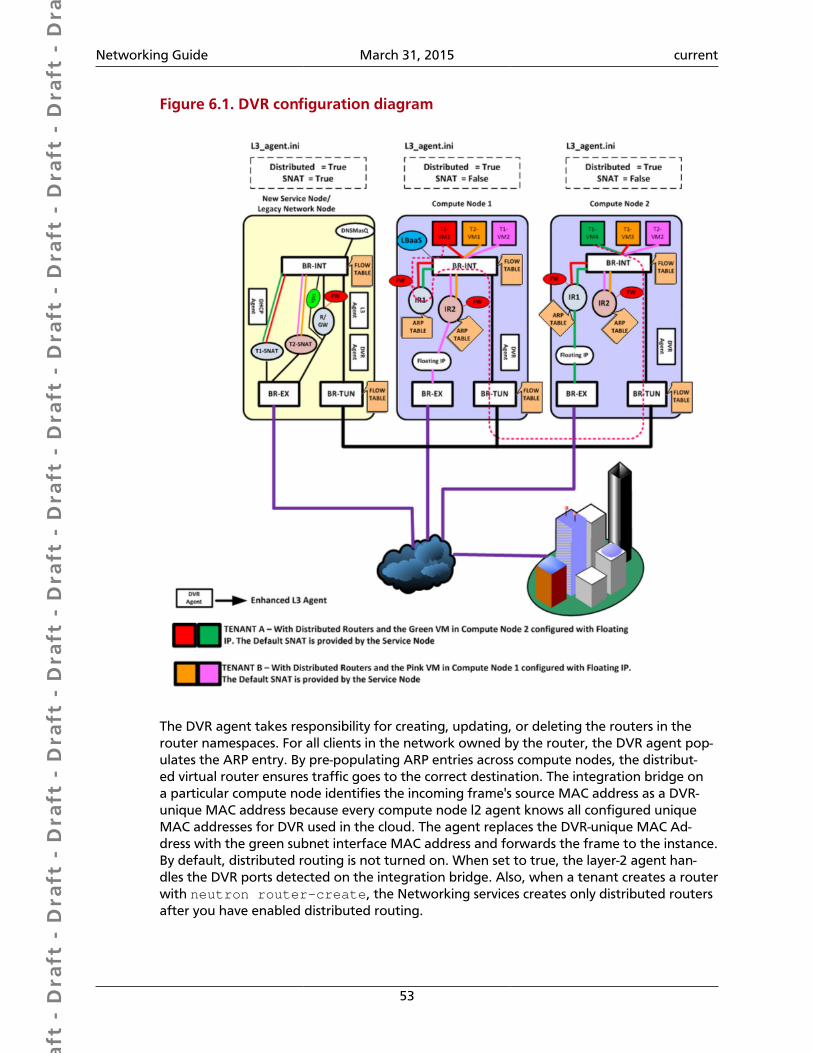
Dra
ft -
Dra
ft -
Dra
ft -
Dra
ft -
Dra
ft -
Dra
ft -
Dra
ft -
Dra
ft -
Dra
ft -
Dra
ft -
Dra
ft -
Dra
ft -
Dra
ft -
Dra
ft -
Dra
ft -
Dra
ft -
Dra
ft -
Dra
ft -
Dra
ft -
Dra
ft -
Dra
ft -
Dra
ft -
Dra
ft -
Dra
ft -
Dra
ft -
Dra
ft -
Dra
ft -
Dra
ft -
Dra
ft -
Dra
ft -
Dra
ft -
Dra
ft -
Dra
ft -
Dra
ft -
Dra
ft -
Networking Guide March 31, 2015 current
53
Figure 6.1. DVR configuration diagram
The DVR agent takes responsibility for creating, updating, or deleting the routers in therouter namespaces. For all clients in the network owned by the router, the DVR agent pop-ulates the ARP entry. By pre-populating ARP entries across compute nodes, the distribut-ed virtual router ensures traffic goes to the correct destination. The integration bridge ona particular compute node identifies the incoming frame's source MAC address as a DVR-unique MAC address because every compute node l2 agent knows all configured uniqueMAC addresses for DVR used in the cloud. The agent replaces the DVR-unique MAC Ad-dress with the green subnet interface MAC address and forwards the frame to the instance.By default, distributed routing is not turned on. When set to true, the layer-2 agent han-dles the DVR ports detected on the integration bridge. Also, when a tenant creates a routerwith neutron router-create, the Networking services creates only distributed routersafter you have enabled distributed routing.
Dra
ft -
Dra
ft -
Dra
ft -
Dra
ft -
Dra
ft -
Dra
ft -
Dra
ft -
Dra
ft -
Dra
ft -
Dra
ft -
Dra
ft -
Dra
ft -
Dra
ft -
Dra
ft -
Dra
ft -
Dra
ft -
Dra
ft -
Dra
ft -
Dra
ft -
Dra
ft -
Dra
ft -
Dra
ft -
Dra
ft -
Dra
ft -
Dra
ft -
Dra
ft -
Dra
ft -
Dra
ft -
Dra
ft -
Dra
ft -
Dra
ft -
Dra
ft -
Dra
ft -
Dra
ft -
Dra
ft -
Networking Guide March 31, 2015 current
54
Configure Distributed Virtual Router (DVR)1. Edit the ovs_neutron_plugin.ini file to change
enable_distributed_routing to True:
enable_distributed_routing = True
2. Edit the /etc/neutron/neutron.conf file to set the base MAC address that theDVR system uses for unique MAC allocation with the dvr_base_mac setting:
dvr_base_mac = fa:16:3f:00:00:00
Note
This dvr_base_mac value must be different from the base_mac valueassigned for virtual ports to ensure port isolation and for troubleshootingpurposes. The default is fa:16:3f:00:00:00. If you want four octetsused, substitute again for the fourth octet (00), otherwise three octets arekept the same and the others are randomly generated.
3. Edit the /etc/neutron/neutron.conf file to set router_distributed toTrue.
router_distributed = True
4. Edit the l3_agent.ini file to set agent_mode to dvr on compute nodes for mul-ti-node deployments:
agent_mode = dvr
Note
When using a separate networking host, set agent_mode to dvr_snat.Use dvr_snat for Devstack or other single-host deployments also.
5. In the [ml2] section, edit the ml2_conf.ini file to add l2population:
[ml2]mechanism_drivers = openvswitch,l2population
6. In the [agent] section of the ml2_conf.ini file, set these configuration options tothese values:
[agent]l2_population = Truetunnel_types = vxlanenable_distributed_routing = True
7. Restart the OVS L2 agent.
• Ubuntu/Debian:
# service neutron-plugin-openvswitch-agent restart restart
• RHEL/CentOS/Fedora:
# service neutron-openvswitch-agent restart
Dra
ft -
Dra
ft -
Dra
ft -
Dra
ft -
Dra
ft -
Dra
ft -
Dra
ft -
Dra
ft -
Dra
ft -
Dra
ft -
Dra
ft -
Dra
ft -
Dra
ft -
Dra
ft -
Dra
ft -
Dra
ft -
Dra
ft -
Dra
ft -
Dra
ft -
Dra
ft -
Dra
ft -
Dra
ft -
Dra
ft -
Dra
ft -
Dra
ft -
Dra
ft -
Dra
ft -
Dra
ft -
Dra
ft -
Dra
ft -
Dra
ft -
Dra
ft -
Dra
ft -
Dra
ft -
Dra
ft -
Networking Guide March 31, 2015 current
55
• SLES/openSUSE:
# service openstack-neutron-openvswitch-agent restart
DVR requirements
• You must use the ML2 plug-in for Open vSwitch (OVS) to enable DVR.
• Be sure that your firewall or security groups allows UDP traffic over the VLAN, GRE, orVXLAN port to pass between the compute hosts.
DVR limitations
• Distributed virtual router configurations work with the Open vSwitch Modular Layer 2driver only for Juno.
• In order to enable true north-south bandwidth between hypervisors (compute nodes),you must use public IP addresses for every compute node and enable floating IPs.
• For now, based on the current neutron design and architecture, DHCP cannot becomedistributed across compute nodes.
Dra
ft -
Dra
ft -
Dra
ft -
Dra
ft -
Dra
ft -
Dra
ft -
Dra
ft -
Dra
ft -
Dra
ft -
Dra
ft -
Dra
ft -
Dra
ft -
Dra
ft -
Dra
ft -
Dra
ft -
Dra
ft -
Dra
ft -
Dra
ft -
Dra
ft -
Dra
ft -
Dra
ft -
Dra
ft -
Dra
ft -
Dra
ft -
Dra
ft -
Dra
ft -
Dra
ft -
Dra
ft -
Dra
ft -
Dra
ft -
Dra
ft -
Dra
ft -
Dra
ft -
Dra
ft -
Dra
ft -
Networking Guide March 31, 2015 current
56
7. Advanced configuration options
Table of ContentsAdvanced agent options ............................................................................................... 56Advanced operational features ..................................................................................... 62Advanced features through API extensions .................................................................... 64Firewall-as-a-Service ....................................................................................................... 81VPN-as-a-service ............................................................................................................. 81Service chaining ............................................................................................................. 81
The following topics describe advanced configuration options for various system compo-nents. For example, configuration options where the default works but that the user wantsto customize options. After installing from packages, $NEUTRON_CONF_DIR is /etc/neu-tron.
Advanced agent optionsThis section describes advanced configuration options for server plug-ins and agents.
OpenStack Networking server with plug-inThis web server runs the OpenStack Networking API Web Server. It loads a plug-in andpasses the API calls to the plug-in for processing. The neutron-server service receivesone or more configuration files as input. For example:
neutron-server --config-file NEUTRON_CONFIG_FILE --config-file PLUGIN_CONFIG_FILE
The neutron configuration file contains the common neutron configuration options.
The plug-in configuration file contains the plug-in specific options.
The plug-in that runs on the service is loaded through the core_plugin configuration op-tion. In some cases, a plug-in might have an agent that performs the actual networking.
Most plug-ins require an SQL database. After you install and start the database server, set apassword for the root account and delete the anonymous accounts:
$ > mysql -u rootmysql> update mysql.user set password = password('iamroot') where user = 'root';mysql> delete from mysql.user where user = '';
Create a database and user account specifically for plug-in:
mysql> create database DATABASE_NAMEmysql> create user 'USER_NAME'@'localhost' identified by 'USER_NAME';mysql> create user 'USER_NAME'@'%' identified by 'USER_NAME';mysql> grant all on DATABASE_NAME.* to 'USER_NAME'@'%';
After this step completes, you can update the settings in the relevant plug-in configurationfiles. Find the plug-in specific configuration files at $NEUTRON_CONF_DIR/plugins.
Dra
ft -
Dra
ft -
Dra
ft -
Dra
ft -
Dra
ft -
Dra
ft -
Dra
ft -
Dra
ft -
Dra
ft -
Dra
ft -
Dra
ft -
Dra
ft -
Dra
ft -
Dra
ft -
Dra
ft -
Dra
ft -
Dra
ft -
Dra
ft -
Dra
ft -
Dra
ft -
Dra
ft -
Dra
ft -
Dra
ft -
Dra
ft -
Dra
ft -
Dra
ft -
Dra
ft -
Dra
ft -
Dra
ft -
Dra
ft -
Dra
ft -
Dra
ft -
Dra
ft -
Dra
ft -
Dra
ft -
Networking Guide March 31, 2015 current
57
Some plug-ins have an L2 agent that performs the actual networking. That is, the agent at-taches the virtual machine NIC to the OpenStack Networking network. Each node shouldrun an L2 agent. Note that the agent receives the following input parameters:
neutron-plugin-agent --config-file NEUTRON_CONFIG_FILE --config-file PLUGIN_CONFIG_FILE
You must complete these tasks before you can work with the plug-in:
1. Ensure that the core plug-in is updated.
2. Ensure that the database connection is correctly set.
The following table shows sample values for the configuration options. Some Linux pack-ages might provide installation utilities that configure these values.
Table 7.1. Settings
Option Value
Open vSwitch
core_plugin ($NEUTRON_CONF_DIR/neutron.conf) openvswitch
connection (in the plugin configuration file, section[database])
mysql://USERNAME:PASSWORD@localhost/ovs_neutron?charset=utf8
Plug-in Configuration File $NEUTRON_CONF_DIR/plugins/open-vswitch/ovs_neutron_plugin.ini
Agent neutron-openvswitch-agent
Linux Bridge
core_plugin ($NEUTRON_CONF_DIR/neutron.conf) linuxbridge
connection (in the plug-in configuration file, section[database])
mysql://USERNAME:PASSWORD@localhost/neutron_linux_bridge?charset=utf8
Plug-in Configuration File $NEUTRON_CONF_DIR/plugins/lin-uxbridge/linuxbridge_conf.ini
Agent neutron-linuxbridge-agent
DHCP agentYou can run a DHCP server that allocates IP addresses to virtual machines that run on thenetwork. When a subnet is created, by default, the subnet has DHCP enabled.
The node that runs the DHCP agent should run:
neutron-dhcp-agent --config-file NEUTRON_CONFIG_FILE --config-file DHCP_CONFIG_FILE
Currently the DHCP agent uses dnsmasq to perform that static address assignment.
You must configure a driver that matches the plug-in that runs on the service.
Table 7.2. Settings
Option Value
Open vSwitch
interface_driver ($NEUTRON_CONF_DIR/dhcp_agent.ini) neutron.agent.linux.interface.OVSInterfaceDriver
Linux Bridge
Dra
ft -
Dra
ft -
Dra
ft -
Dra
ft -
Dra
ft -
Dra
ft -
Dra
ft -
Dra
ft -
Dra
ft -
Dra
ft -
Dra
ft -
Dra
ft -
Dra
ft -
Dra
ft -
Dra
ft -
Dra
ft -
Dra
ft -
Dra
ft -
Dra
ft -
Dra
ft -
Dra
ft -
Dra
ft -
Dra
ft -
Dra
ft -
Dra
ft -
Dra
ft -
Dra
ft -
Dra
ft -
Dra
ft -
Dra
ft -
Dra
ft -
Dra
ft -
Dra
ft -
Dra
ft -
Dra
ft -
Networking Guide March 31, 2015 current
58
Option Value
interface_driver ($NEUTRON_CONF_DIR/dhcp_agent.ini) neutron.agent.linux.interface.BridgeInterfaceDriver
Namespace
By default, the DHCP agent uses Linux network namespaces to support overlapping IP ad-dresses. For information about network namespaces support, see the Limitations section.
If the Linux installation does not support network namespaces, you must disable networknamespaces in the DHCP agent configuration file. The default value of use_namespacesis True.
use_namespaces = False
L3 agent
You can run an L3 agent that enables layer 3 forwarding and floating IP support.
The node that runs the L3 agent should run:
neutron-l3-agent --config-file NEUTRON_CONFIG_FILE --config-file L3_CONFIG_FILE
You must configure a driver that matches the plug-in that runs on the service. This drivercreates the routing interface.
Table 7.3. Settings
Option Value
Open vSwitch
interface_driver ($NEUTRON_CONF_DIR/l3_agent.ini) neutron.agent.linux.interface.OVSInterfaceDriver
external_network_bridge ($NEUTRON_CONF_DIR/l3_agent.ini)
br-ex
Linux Bridge
interface_driver ($NEUTRON_CONF_DIR/l3_agent.ini) neutron.agent.linux.interface.BridgeInterfaceDriver
external_network_bridge ($NEUTRON_CONF_DIR/l3_agent.ini)
This field must be empty (or the bridge name for the ex-ternal network).
The L3 agent communicates with the OpenStack Networking server through the OpenStackNetworking API, so the following configuration is required:
1. OpenStack Identity authentication:
auth_url="$KEYSTONE_SERVICE_PROTOCOL://$KEYSTONE_AUTH_HOST:$KEYSTONE_AUTH_PORT/v2.0"
For example:
http://10.56.51.210:5000/v2.0
2. Administrative user details:
admin_tenant_name $SERVICE_TENANT_NAMEadmin_user $Q_ADMIN_USERNAMEadmin_password $SERVICE_PASSWORD
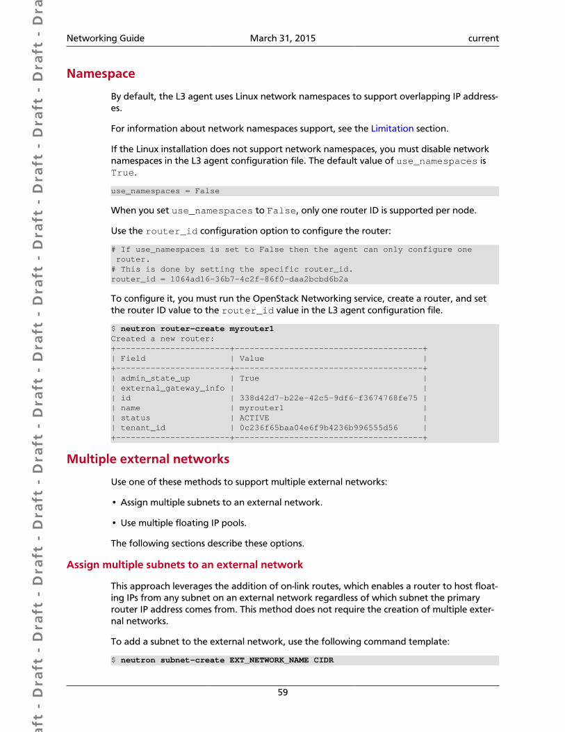
Dra
ft -
Dra
ft -
Dra
ft -
Dra
ft -
Dra
ft -
Dra
ft -
Dra
ft -
Dra
ft -
Dra
ft -
Dra
ft -
Dra
ft -
Dra
ft -
Dra
ft -
Dra
ft -
Dra
ft -
Dra
ft -
Dra
ft -
Dra
ft -
Dra
ft -
Dra
ft -
Dra
ft -
Dra
ft -
Dra
ft -
Dra
ft -
Dra
ft -
Dra
ft -
Dra
ft -
Dra
ft -
Dra
ft -
Dra
ft -
Dra
ft -
Dra
ft -
Dra
ft -
Dra
ft -
Dra
ft -
Networking Guide March 31, 2015 current
59
Namespace
By default, the L3 agent uses Linux network namespaces to support overlapping IP address-es.
For information about network namespaces support, see the Limitation section.
If the Linux installation does not support network namespaces, you must disable networknamespaces in the L3 agent configuration file. The default value of use_namespaces isTrue.
use_namespaces = False
When you set use_namespaces to False, only one router ID is supported per node.
Use the router_id configuration option to configure the router:
# If use_namespaces is set to False then the agent can only configure one router.# This is done by setting the specific router_id.router_id = 1064ad16-36b7-4c2f-86f0-daa2bcbd6b2a
To configure it, you must run the OpenStack Networking service, create a router, and setthe router ID value to the router_id value in the L3 agent configuration file.
$ neutron router-create myrouter1Created a new router:+-----------------------+--------------------------------------+| Field | Value |+-----------------------+--------------------------------------+| admin_state_up | True || external_gateway_info | || id | 338d42d7-b22e-42c5-9df6-f3674768fe75 || name | myrouter1 || status | ACTIVE || tenant_id | 0c236f65baa04e6f9b4236b996555d56 |+-----------------------+--------------------------------------+
Multiple external networks
Use one of these methods to support multiple external networks:
• Assign multiple subnets to an external network.
• Use multiple floating IP pools.
The following sections describe these options.
Assign multiple subnets to an external network
This approach leverages the addition of on-link routes, which enables a router to host float-ing IPs from any subnet on an external network regardless of which subnet the primaryrouter IP address comes from. This method does not require the creation of multiple exter-nal networks.
To add a subnet to the external network, use the following command template:
$ neutron subnet-create EXT_NETWORK_NAME CIDR
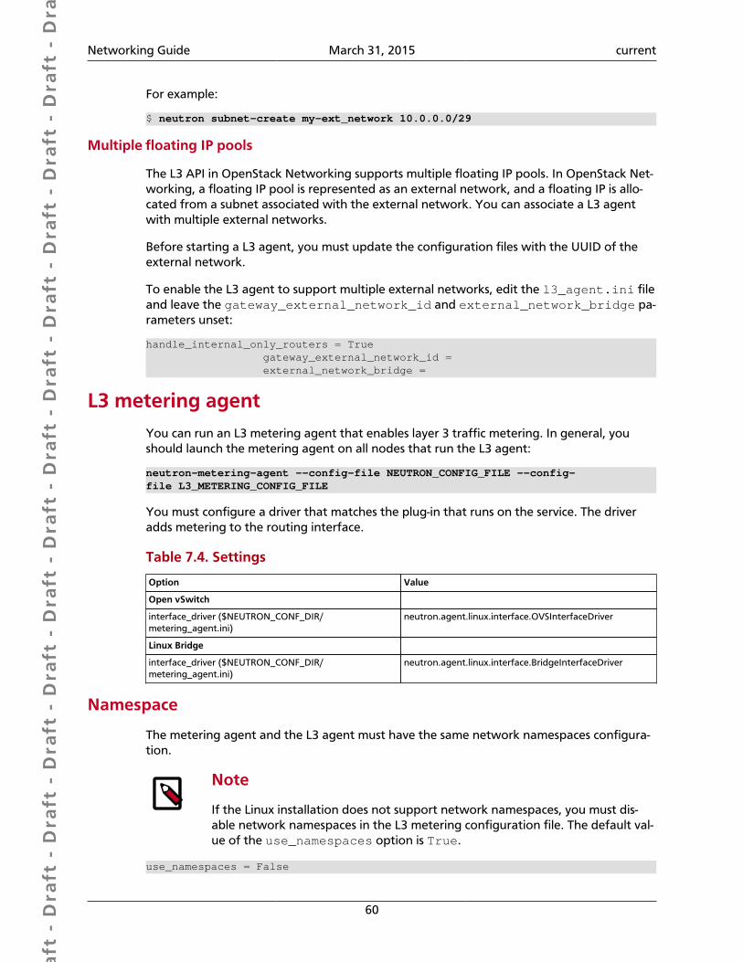
Dra
ft -
Dra
ft -
Dra
ft -
Dra
ft -
Dra
ft -
Dra
ft -
Dra
ft -
Dra
ft -
Dra
ft -
Dra
ft -
Dra
ft -
Dra
ft -
Dra
ft -
Dra
ft -
Dra
ft -
Dra
ft -
Dra
ft -
Dra
ft -
Dra
ft -
Dra
ft -
Dra
ft -
Dra
ft -
Dra
ft -
Dra
ft -
Dra
ft -
Dra
ft -
Dra
ft -
Dra
ft -
Dra
ft -
Dra
ft -
Dra
ft -
Dra
ft -
Dra
ft -
Dra
ft -
Dra
ft -
Networking Guide March 31, 2015 current
60
For example:
$ neutron subnet-create my-ext_network 10.0.0.0/29
Multiple floating IP pools
The L3 API in OpenStack Networking supports multiple floating IP pools. In OpenStack Net-working, a floating IP pool is represented as an external network, and a floating IP is allo-cated from a subnet associated with the external network. You can associate a L3 agentwith multiple external networks.
Before starting a L3 agent, you must update the configuration files with the UUID of theexternal network.
To enable the L3 agent to support multiple external networks, edit the l3_agent.ini fileand leave the gateway_external_network_id and external_network_bridge pa-rameters unset:
handle_internal_only_routers = True gateway_external_network_id = external_network_bridge =
L3 metering agentYou can run an L3 metering agent that enables layer 3 traffic metering. In general, youshould launch the metering agent on all nodes that run the L3 agent:
neutron-metering-agent --config-file NEUTRON_CONFIG_FILE --config-file L3_METERING_CONFIG_FILE
You must configure a driver that matches the plug-in that runs on the service. The driveradds metering to the routing interface.
Table 7.4. Settings
Option Value
Open vSwitch
interface_driver ($NEUTRON_CONF_DIR/metering_agent.ini)
neutron.agent.linux.interface.OVSInterfaceDriver
Linux Bridge
interface_driver ($NEUTRON_CONF_DIR/metering_agent.ini)
neutron.agent.linux.interface.BridgeInterfaceDriver
Namespace
The metering agent and the L3 agent must have the same network namespaces configura-tion.
Note
If the Linux installation does not support network namespaces, you must dis-able network namespaces in the L3 metering configuration file. The default val-ue of the use_namespaces option is True.
use_namespaces = False

Dra
ft -
Dra
ft -
Dra
ft -
Dra
ft -
Dra
ft -
Dra
ft -
Dra
ft -
Dra
ft -
Dra
ft -
Dra
ft -
Dra
ft -
Dra
ft -
Dra
ft -
Dra
ft -
Dra
ft -
Dra
ft -
Dra
ft -
Dra
ft -
Dra
ft -
Dra
ft -
Dra
ft -
Dra
ft -
Dra
ft -
Dra
ft -
Dra
ft -
Dra
ft -
Dra
ft -
Dra
ft -
Dra
ft -
Dra
ft -
Dra
ft -
Dra
ft -
Dra
ft -
Dra
ft -
Dra
ft -
Networking Guide March 31, 2015 current
61
L3 metering driver
You must configure any driver that implements the metering abstraction. Currently the on-ly available implementation uses iptables for metering.
driver = neutron.services.metering.drivers.iptables.iptables_driver.IptablesMeteringDriver
L3 metering service driver
To enable L3 metering, you must set the following option in the neutron.conf file on thehost that runs neutron-server:
service_plugins = metering
Limitations• No equivalent for nova-network --multi_host option. Nova-network has a model
where the L3, NAT, and DHCP processing happen on the compute node itself, ratherthan a dedicated networking node. OpenStack Networking now support running multi-ple l3-agent and dhcp-agents with load being split across those agents, but the tight cou-pling of that scheduling with the location of the VM is not supported in Icehouse. TheJuno release is expected to include an exact replacement for the --multi_host optionin nova-network.
• Linux network namespace required on nodes running neutron-l3-agent or neu-tron-dhcp-agent if overlapping IPs are in use. To support overlapping IP addresses,the OpenStack Networking DHCP and L3 agents use Linux network namespaces by de-fault. The hosts running these processes must support network namespaces. To supportnetwork namespaces, the following are required:
• Linux kernel 2.6.24 or later (with CONFIG_NET_NS=y in kernel configuration)
• iproute2 utilities ('ip' command) version 3.1.0 (aka 20111117) or later
To check whether your host supports namespaces, run these commands as root:
# ip netns add test-ns# ip netns exec test-ns ifconfig
If these commands succeed, your platform is likely sufficient to use the dhcp-agent or l3-agent with namespaces. In our experience, Ubuntu 12.04 or later support namespaces asdoes Fedora 17 and later, but some earlier RHEL platforms do not by default. It might bepossible to upgrade the iproute2 package on a platform that does not support names-paces by default.
If you must disable namespaces, make sure that the neutron.conf file that is used byneutron-server has the following setting:
allow_overlapping_ips=False
Also, ensure that the dhcp_agent.ini and l3_agent.ini files have the followingsetting:
use_namespaces=False
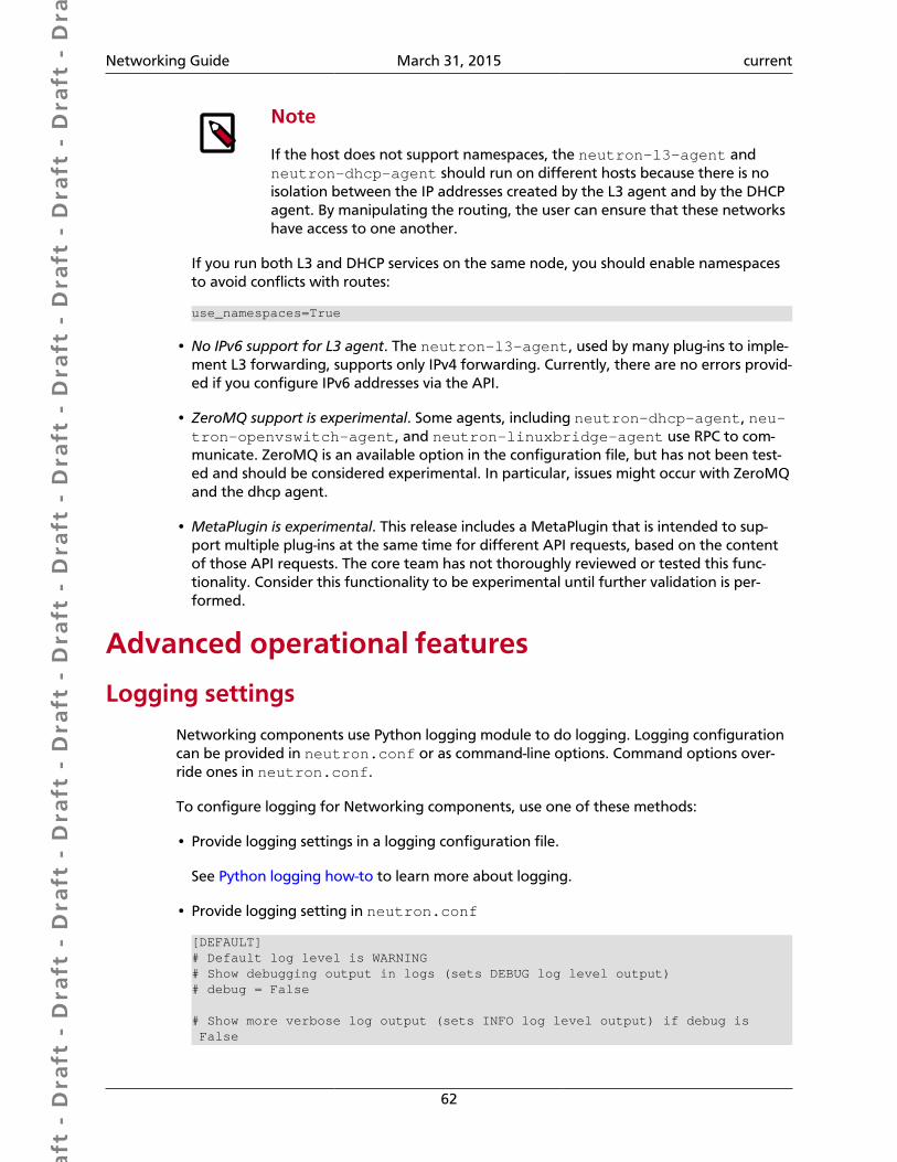
Dra
ft -
Dra
ft -
Dra
ft -
Dra
ft -
Dra
ft -
Dra
ft -
Dra
ft -
Dra
ft -
Dra
ft -
Dra
ft -
Dra
ft -
Dra
ft -
Dra
ft -
Dra
ft -
Dra
ft -
Dra
ft -
Dra
ft -
Dra
ft -
Dra
ft -
Dra
ft -
Dra
ft -
Dra
ft -
Dra
ft -
Dra
ft -
Dra
ft -
Dra
ft -
Dra
ft -
Dra
ft -
Dra
ft -
Dra
ft -
Dra
ft -
Dra
ft -
Dra
ft -
Dra
ft -
Dra
ft -
Networking Guide March 31, 2015 current
62
Note
If the host does not support namespaces, the neutron-l3-agent andneutron-dhcp-agent should run on different hosts because there is noisolation between the IP addresses created by the L3 agent and by the DHCPagent. By manipulating the routing, the user can ensure that these networkshave access to one another.
If you run both L3 and DHCP services on the same node, you should enable namespacesto avoid conflicts with routes:
use_namespaces=True
• No IPv6 support for L3 agent. The neutron-l3-agent, used by many plug-ins to imple-ment L3 forwarding, supports only IPv4 forwarding. Currently, there are no errors provid-ed if you configure IPv6 addresses via the API.
• ZeroMQ support is experimental. Some agents, including neutron-dhcp-agent, neu-tron-openvswitch-agent, and neutron-linuxbridge-agent use RPC to com-municate. ZeroMQ is an available option in the configuration file, but has not been test-ed and should be considered experimental. In particular, issues might occur with ZeroMQand the dhcp agent.
• MetaPlugin is experimental. This release includes a MetaPlugin that is intended to sup-port multiple plug-ins at the same time for different API requests, based on the contentof those API requests. The core team has not thoroughly reviewed or tested this func-tionality. Consider this functionality to be experimental until further validation is per-formed.
Advanced operational features
Logging settings
Networking components use Python logging module to do logging. Logging configurationcan be provided in neutron.conf or as command-line options. Command options over-ride ones in neutron.conf.
To configure logging for Networking components, use one of these methods:
• Provide logging settings in a logging configuration file.
See Python logging how-to to learn more about logging.
• Provide logging setting in neutron.conf
[DEFAULT]# Default log level is WARNING# Show debugging output in logs (sets DEBUG log level output)# debug = False
# Show more verbose log output (sets INFO log level output) if debug is False
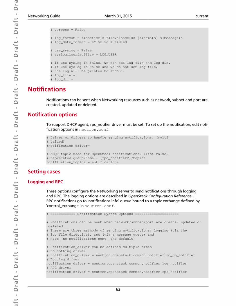
Dra
ft -
Dra
ft -
Dra
ft -
Dra
ft -
Dra
ft -
Dra
ft -
Dra
ft -
Dra
ft -
Dra
ft -
Dra
ft -
Dra
ft -
Dra
ft -
Dra
ft -
Dra
ft -
Dra
ft -
Dra
ft -
Dra
ft -
Dra
ft -
Dra
ft -
Dra
ft -
Dra
ft -
Dra
ft -
Dra
ft -
Dra
ft -
Dra
ft -
Dra
ft -
Dra
ft -
Dra
ft -
Dra
ft -
Dra
ft -
Dra
ft -
Dra
ft -
Dra
ft -
Dra
ft -
Dra
ft -
Networking Guide March 31, 2015 current
63
# verbose = False
# log_format = %(asctime)s %(levelname)8s [%(name)s] %(message)s# log_date_format = %Y-%m-%d %H:%M:%S
# use_syslog = False# syslog_log_facility = LOG_USER
# if use_syslog is False, we can set log_file and log_dir.# if use_syslog is False and we do not set log_file,# the log will be printed to stdout.# log_file =# log_dir =
Notifications
Notifications can be sent when Networking resources such as network, subnet and port arecreated, updated or deleted.
Notification options
To support DHCP agent, rpc_notifier driver must be set. To set up the notification, edit noti-fication options in neutron.conf:
# Driver or drivers to handle sending notifications. (multi# valued)#notification_driver=
# AMQP topic used for OpenStack notifications. (list value)# Deprecated group/name - [rpc_notifier2]/topicsnotification_topics = notifications
Setting cases
Logging and RPC
These options configure the Networking server to send notifications through loggingand RPC. The logging options are described in OpenStack Configuration Reference .RPC notifications go to 'notifications.info' queue bound to a topic exchange defined by'control_exchange' in neutron.conf.
# ============ Notification System Options =====================
# Notifications can be sent when network/subnet/port are create, updated or deleted.# There are three methods of sending notifications: logging (via the# log_file directive), rpc (via a message queue) and# noop (no notifications sent, the default)
# Notification_driver can be defined multiple times# Do nothing driver# notification_driver = neutron.openstack.common.notifier.no_op_notifier# Logging drivernotification_driver = neutron.openstack.common.notifier.log_notifier# RPC drivernotification_driver = neutron.openstack.common.notifier.rpc_notifier
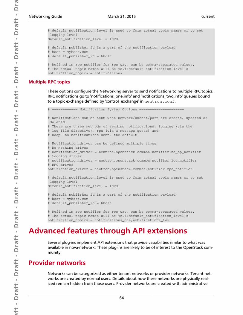
Dra
ft -
Dra
ft -
Dra
ft -
Dra
ft -
Dra
ft -
Dra
ft -
Dra
ft -
Dra
ft -
Dra
ft -
Dra
ft -
Dra
ft -
Dra
ft -
Dra
ft -
Dra
ft -
Dra
ft -
Dra
ft -
Dra
ft -
Dra
ft -
Dra
ft -
Dra
ft -
Dra
ft -
Dra
ft -
Dra
ft -
Dra
ft -
Dra
ft -
Dra
ft -
Dra
ft -
Dra
ft -
Dra
ft -
Dra
ft -
Dra
ft -
Dra
ft -
Dra
ft -
Dra
ft -
Dra
ft -
Networking Guide March 31, 2015 current
64
# default_notification_level is used to form actual topic names or to set logging leveldefault_notification_level = INFO
# default_publisher_id is a part of the notification payload# host = myhost.com# default_publisher_id = $host
# Defined in rpc_notifier for rpc way, can be comma-separated values.# The actual topic names will be %s.%(default_notification_level)snotification_topics = notifications
Multiple RPC topics
These options configure the Networking server to send notifications to multiple RPC topics.RPC notifications go to 'notifications_one.info' and 'notifications_two.info' queues boundto a topic exchange defined by 'control_exchange' in neutron.conf.
# ============ Notification System Options =====================
# Notifications can be sent when network/subnet/port are create, updated or deleted.# There are three methods of sending notifications: logging (via the# log_file directive), rpc (via a message queue) and# noop (no notifications sent, the default)
# Notification_driver can be defined multiple times# Do nothing driver# notification_driver = neutron.openstack.common.notifier.no_op_notifier# Logging driver# notification_driver = neutron.openstack.common.notifier.log_notifier# RPC drivernotification_driver = neutron.openstack.common.notifier.rpc_notifier
# default_notification_level is used to form actual topic names or to set logging leveldefault_notification_level = INFO
# default_publisher_id is a part of the notification payload# host = myhost.com# default_publisher_id = $host
# Defined in rpc_notifier for rpc way, can be comma-separated values.# The actual topic names will be %s.%(default_notification_level)snotification_topics = notifications_one,notifications_two
Advanced features through API extensionsSeveral plug-ins implement API extensions that provide capabilities similar to what wasavailable in nova-network: These plug-ins are likely to be of interest to the OpenStack com-munity.
Provider networksNetworks can be categorized as either tenant networks or provider networks. Tenant net-works are created by normal users. Details about how these networks are physically real-ized remain hidden from those users. Provider networks are created with administrative
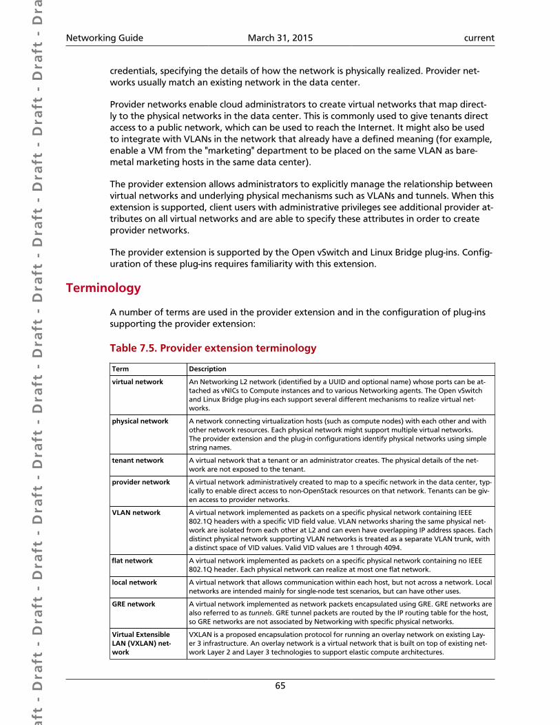
Dra
ft -
Dra
ft -
Dra
ft -
Dra
ft -
Dra
ft -
Dra
ft -
Dra
ft -
Dra
ft -
Dra
ft -
Dra
ft -
Dra
ft -
Dra
ft -
Dra
ft -
Dra
ft -
Dra
ft -
Dra
ft -
Dra
ft -
Dra
ft -
Dra
ft -
Dra
ft -
Dra
ft -
Dra
ft -
Dra
ft -
Dra
ft -
Dra
ft -
Dra
ft -
Dra
ft -
Dra
ft -
Dra
ft -
Dra
ft -
Dra
ft -
Dra
ft -
Dra
ft -
Dra
ft -
Dra
ft -
Networking Guide March 31, 2015 current
65
credentials, specifying the details of how the network is physically realized. Provider net-works usually match an existing network in the data center.
Provider networks enable cloud administrators to create virtual networks that map direct-ly to the physical networks in the data center. This is commonly used to give tenants directaccess to a public network, which can be used to reach the Internet. It might also be usedto integrate with VLANs in the network that already have a defined meaning (for example,enable a VM from the "marketing" department to be placed on the same VLAN as bare-metal marketing hosts in the same data center).
The provider extension allows administrators to explicitly manage the relationship betweenvirtual networks and underlying physical mechanisms such as VLANs and tunnels. When thisextension is supported, client users with administrative privileges see additional provider at-tributes on all virtual networks and are able to specify these attributes in order to createprovider networks.
The provider extension is supported by the Open vSwitch and Linux Bridge plug-ins. Config-uration of these plug-ins requires familiarity with this extension.
Terminology
A number of terms are used in the provider extension and in the configuration of plug-inssupporting the provider extension:
Table 7.5. Provider extension terminology
Term Description
virtual network An Networking L2 network (identified by a UUID and optional name) whose ports can be at-tached as vNICs to Compute instances and to various Networking agents. The Open vSwitchand Linux Bridge plug-ins each support several different mechanisms to realize virtual net-works.
physical network A network connecting virtualization hosts (such as compute nodes) with each other and withother network resources. Each physical network might support multiple virtual networks.The provider extension and the plug-in configurations identify physical networks using simplestring names.
tenant network A virtual network that a tenant or an administrator creates. The physical details of the net-work are not exposed to the tenant.
provider network A virtual network administratively created to map to a specific network in the data center, typ-ically to enable direct access to non-OpenStack resources on that network. Tenants can be giv-en access to provider networks.
VLAN network A virtual network implemented as packets on a specific physical network containing IEEE802.1Q headers with a specific VID field value. VLAN networks sharing the same physical net-work are isolated from each other at L2 and can even have overlapping IP address spaces. Eachdistinct physical network supporting VLAN networks is treated as a separate VLAN trunk, witha distinct space of VID values. Valid VID values are 1 through 4094.
flat network A virtual network implemented as packets on a specific physical network containing no IEEE802.1Q header. Each physical network can realize at most one flat network.
local network A virtual network that allows communication within each host, but not across a network. Localnetworks are intended mainly for single-node test scenarios, but can have other uses.
GRE network A virtual network implemented as network packets encapsulated using GRE. GRE networks arealso referred to as tunnels. GRE tunnel packets are routed by the IP routing table for the host,so GRE networks are not associated by Networking with specific physical networks.
Virtual ExtensibleLAN (VXLAN) net-work
VXLAN is a proposed encapsulation protocol for running an overlay network on existing Lay-er 3 infrastructure. An overlay network is a virtual network that is built on top of existing net-work Layer 2 and Layer 3 technologies to support elastic compute architectures.
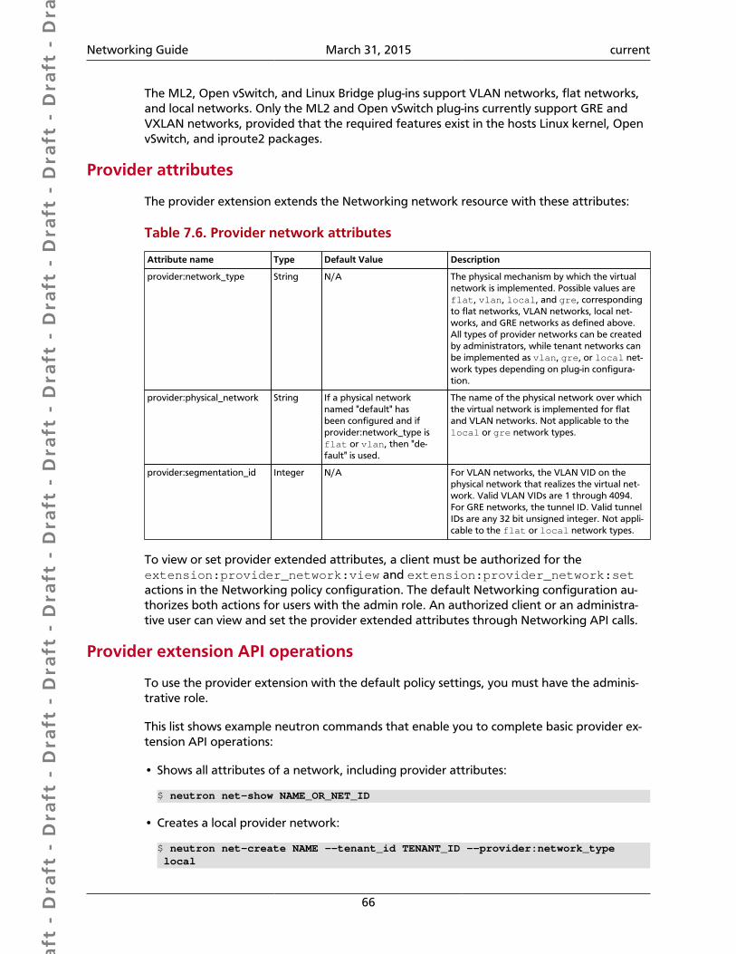
Dra
ft -
Dra
ft -
Dra
ft -
Dra
ft -
Dra
ft -
Dra
ft -
Dra
ft -
Dra
ft -
Dra
ft -
Dra
ft -
Dra
ft -
Dra
ft -
Dra
ft -
Dra
ft -
Dra
ft -
Dra
ft -
Dra
ft -
Dra
ft -
Dra
ft -
Dra
ft -
Dra
ft -
Dra
ft -
Dra
ft -
Dra
ft -
Dra
ft -
Dra
ft -
Dra
ft -
Dra
ft -
Dra
ft -
Dra
ft -
Dra
ft -
Dra
ft -
Dra
ft -
Dra
ft -
Dra
ft -
Networking Guide March 31, 2015 current
66
The ML2, Open vSwitch, and Linux Bridge plug-ins support VLAN networks, flat networks,and local networks. Only the ML2 and Open vSwitch plug-ins currently support GRE andVXLAN networks, provided that the required features exist in the hosts Linux kernel, OpenvSwitch, and iproute2 packages.
Provider attributes
The provider extension extends the Networking network resource with these attributes:
Table 7.6. Provider network attributes
Attribute name Type Default Value Description
provider:network_type String N/A The physical mechanism by which the virtualnetwork is implemented. Possible values areflat, vlan, local, and gre, correspondingto flat networks, VLAN networks, local net-works, and GRE networks as defined above.All types of provider networks can be createdby administrators, while tenant networks canbe implemented as vlan, gre, or local net-work types depending on plug-in configura-tion.
provider:physical_network String If a physical networknamed "default" hasbeen configured and ifprovider:network_type isflat or vlan, then "de-fault" is used.
The name of the physical network over whichthe virtual network is implemented for flatand VLAN networks. Not applicable to thelocal or gre network types.
provider:segmentation_id Integer N/A For VLAN networks, the VLAN VID on thephysical network that realizes the virtual net-work. Valid VLAN VIDs are 1 through 4094.For GRE networks, the tunnel ID. Valid tunnelIDs are any 32 bit unsigned integer. Not appli-cable to the flat or local network types.
To view or set provider extended attributes, a client must be authorized for theextension:provider_network:view and extension:provider_network:setactions in the Networking policy configuration. The default Networking configuration au-thorizes both actions for users with the admin role. An authorized client or an administra-tive user can view and set the provider extended attributes through Networking API calls.
Provider extension API operations
To use the provider extension with the default policy settings, you must have the adminis-trative role.
This list shows example neutron commands that enable you to complete basic provider ex-tension API operations:
• Shows all attributes of a network, including provider attributes:
$ neutron net-show NAME_OR_NET_ID
• Creates a local provider network:
$ neutron net-create NAME --tenant_id TENANT_ID --provider:network_type local

Dra
ft -
Dra
ft -
Dra
ft -
Dra
ft -
Dra
ft -
Dra
ft -
Dra
ft -
Dra
ft -
Dra
ft -
Dra
ft -
Dra
ft -
Dra
ft -
Dra
ft -
Dra
ft -
Dra
ft -
Dra
ft -
Dra
ft -
Dra
ft -
Dra
ft -
Dra
ft -
Dra
ft -
Dra
ft -
Dra
ft -
Dra
ft -
Dra
ft -
Dra
ft -
Dra
ft -
Dra
ft -
Dra
ft -
Dra
ft -
Dra
ft -
Dra
ft -
Dra
ft -
Dra
ft -
Dra
ft -
Networking Guide March 31, 2015 current
67
• When you create flat networks, PHYS_NET_NAME must be known to the plug-in. See theOpenStack Configuration Reference for details. Creates a flat provider network:
$ neutron net-create NAME --tenant_id TENANT_ID --provider:network_type flat --provider:physical_network PHYS_NET_NAME
• When you create VLAN networks, PHYS_NET_NAME must be known to the plug-in. Seethe OpenStack Configuration Reference for details on configuring network_vlan_rangesto identify all physical networks. When you create VLAN networks, VID can fall eitherwithin or outside any configured ranges of VLAN IDs from which tenant networks are al-located. Creates a VLAN provider network:
$ neutron net-create NAME --tenant_id TENANT_ID --provider:network_type vlan --provider:physical_network PHYS_NET_NAME --provider:segmentation_id VID
• When you create GRE networks, TUNNEL_ID can be either inside or outside any tunnelID ranges from which tenant networks are allocated.
After you create provider networks, you can allocate subnets, which you can use in thesame way as other virtual networks, subject to authorization policy based on the speci-fied TENANT_ID. Creates a GRE provider network:
$ neutron net-create NAME --tenant_id TENANT_ID --provider:network_type gre --provider:segmentation_id TUNNEL_ID
L3 routing and NAT
The Networking API provides abstract L2 network segments that are decoupled from thetechnology used to implement the L2 network. Networking includes an API extension thatprovides abstract L3 routers that API users can dynamically provision and configure. TheseNetworking routers can connect multiple L2 Networking networks and can also provide agateway that connects one or more private L2 networks to a shared external network. Forexample, a public network for access to the Internet. See the OpenStack Configuration Ref-erence for details on common models of deploying Networking L3 routers.
The L3 router provides basic NAT capabilities on gateway ports that uplink the router toexternal networks. This router SNATs all traffic by default and supports floating IPs, whichcreates a static one-to-one mapping from a public IP on the external network to a privateIP on one of the other subnets attached to the router. This allows a tenant to selectivelyexpose VMs on private networks to other hosts on the external network (and often to allhosts on the Internet). You can allocate and map floating IPs from one port to another, asneeded.
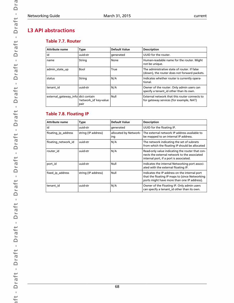
Dra
ft -
Dra
ft -
Dra
ft -
Dra
ft -
Dra
ft -
Dra
ft -
Dra
ft -
Dra
ft -
Dra
ft -
Dra
ft -
Dra
ft -
Dra
ft -
Dra
ft -
Dra
ft -
Dra
ft -
Dra
ft -
Dra
ft -
Dra
ft -
Dra
ft -
Dra
ft -
Dra
ft -
Dra
ft -
Dra
ft -
Dra
ft -
Dra
ft -
Dra
ft -
Dra
ft -
Dra
ft -
Dra
ft -
Dra
ft -
Dra
ft -
Dra
ft -
Dra
ft -
Dra
ft -
Dra
ft -
Networking Guide March 31, 2015 current
68
L3 API abstractions
Table 7.7. Router
Attribute name Type Default Value Description
id uuid-str generated UUID for the router.
name String None Human-readable name for the router. Mightnot be unique.
admin_state_up Bool True The administrative state of router. If false(down), the router does not forward packets.
status String N/A Indicates whether router is currently opera-tional.
tenant_id uuid-str N/A Owner of the router. Only admin users canspecify a tenant_id other than its own.
external_gateway_info dict contain'network_id' key-valuepair
Null External network that this router connects tofor gateway services (for example, NAT)
Table 7.8. Floating IP
Attribute name Type Default Value Description
id uuid-str generated UUID for the floating IP.
floating_ip_address string (IP address) allocated by Network-ing
The external network IP address available tobe mapped to an internal IP address.
floating_network_id uuid-str N/A The network indicating the set of subnetsfrom which the floating IP should be allocated
router_id uuid-str N/A Read-only value indicating the router that con-nects the external network to the associatedinternal port, if a port is associated.
port_id uuid-str Null Indicates the internal Networking port associ-ated with the external floating IP.
fixed_ip_address string (IP address) Null Indicates the IP address on the internal portthat the floating IP maps to (since Networkingports might have more than one IP address).
tenant_id uuid-str N/A Owner of the Floating IP. Only admin userscan specify a tenant_id other than its own.
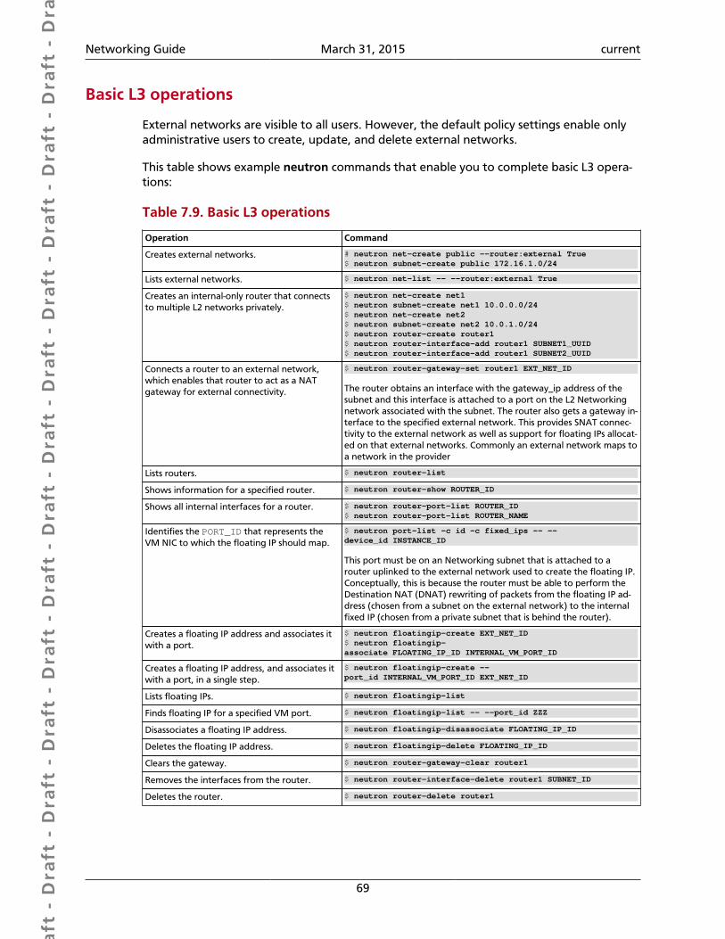
Dra
ft -
Dra
ft -
Dra
ft -
Dra
ft -
Dra
ft -
Dra
ft -
Dra
ft -
Dra
ft -
Dra
ft -
Dra
ft -
Dra
ft -
Dra
ft -
Dra
ft -
Dra
ft -
Dra
ft -
Dra
ft -
Dra
ft -
Dra
ft -
Dra
ft -
Dra
ft -
Dra
ft -
Dra
ft -
Dra
ft -
Dra
ft -
Dra
ft -
Dra
ft -
Dra
ft -
Dra
ft -
Dra
ft -
Dra
ft -
Dra
ft -
Dra
ft -
Dra
ft -
Dra
ft -
Dra
ft -
Networking Guide March 31, 2015 current
69
Basic L3 operations
External networks are visible to all users. However, the default policy settings enable onlyadministrative users to create, update, and delete external networks.
This table shows example neutron commands that enable you to complete basic L3 opera-tions:
Table 7.9. Basic L3 operations
Operation Command
Creates external networks. # neutron net-create public --router:external True$ neutron subnet-create public 172.16.1.0/24
Lists external networks. $ neutron net-list -- --router:external True
Creates an internal-only router that connectsto multiple L2 networks privately.
$ neutron net-create net1$ neutron subnet-create net1 10.0.0.0/24$ neutron net-create net2$ neutron subnet-create net2 10.0.1.0/24$ neutron router-create router1$ neutron router-interface-add router1 SUBNET1_UUID$ neutron router-interface-add router1 SUBNET2_UUID
Connects a router to an external network,which enables that router to act as a NATgateway for external connectivity.
$ neutron router-gateway-set router1 EXT_NET_ID
The router obtains an interface with the gateway_ip address of thesubnet and this interface is attached to a port on the L2 Networkingnetwork associated with the subnet. The router also gets a gateway in-terface to the specified external network. This provides SNAT connec-tivity to the external network as well as support for floating IPs allocat-ed on that external networks. Commonly an external network maps toa network in the provider
Lists routers. $ neutron router-list
Shows information for a specified router. $ neutron router-show ROUTER_ID
Shows all internal interfaces for a router. $ neutron router-port-list ROUTER_ID$ neutron router-port-list ROUTER_NAME
Identifies the PORT_ID that represents theVM NIC to which the floating IP should map.
$ neutron port-list -c id -c fixed_ips -- --device_id INSTANCE_ID
This port must be on an Networking subnet that is attached to arouter uplinked to the external network used to create the floating IP.Conceptually, this is because the router must be able to perform theDestination NAT (DNAT) rewriting of packets from the floating IP ad-dress (chosen from a subnet on the external network) to the internalfixed IP (chosen from a private subnet that is behind the router).
Creates a floating IP address and associates itwith a port.
$ neutron floatingip-create EXT_NET_ID$ neutron floatingip-associate FLOATING_IP_ID INTERNAL_VM_PORT_ID
Creates a floating IP address, and associates itwith a port, in a single step.
$ neutron floatingip-create --port_id INTERNAL_VM_PORT_ID EXT_NET_ID
Lists floating IPs. $ neutron floatingip-list
Finds floating IP for a specified VM port. $ neutron floatingip-list -- --port_id ZZZ
Disassociates a floating IP address. $ neutron floatingip-disassociate FLOATING_IP_ID
Deletes the floating IP address. $ neutron floatingip-delete FLOATING_IP_ID
Clears the gateway. $ neutron router-gateway-clear router1
Removes the interfaces from the router. $ neutron router-interface-delete router1 SUBNET_ID
Deletes the router. $ neutron router-delete router1
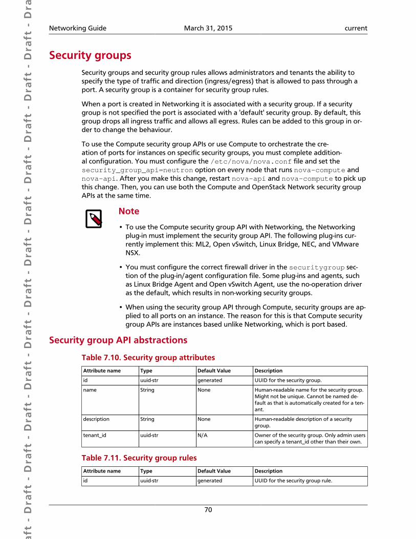
Dra
ft -
Dra
ft -
Dra
ft -
Dra
ft -
Dra
ft -
Dra
ft -
Dra
ft -
Dra
ft -
Dra
ft -
Dra
ft -
Dra
ft -
Dra
ft -
Dra
ft -
Dra
ft -
Dra
ft -
Dra
ft -
Dra
ft -
Dra
ft -
Dra
ft -
Dra
ft -
Dra
ft -
Dra
ft -
Dra
ft -
Dra
ft -
Dra
ft -
Dra
ft -
Dra
ft -
Dra
ft -
Dra
ft -
Dra
ft -
Dra
ft -
Dra
ft -
Dra
ft -
Dra
ft -
Dra
ft -
Networking Guide March 31, 2015 current
70
Security groupsSecurity groups and security group rules allows administrators and tenants the ability tospecify the type of traffic and direction (ingress/egress) that is allowed to pass through aport. A security group is a container for security group rules.
When a port is created in Networking it is associated with a security group. If a securitygroup is not specified the port is associated with a 'default' security group. By default, thisgroup drops all ingress traffic and allows all egress. Rules can be added to this group in or-der to change the behaviour.
To use the Compute security group APIs or use Compute to orchestrate the cre-ation of ports for instances on specific security groups, you must complete addition-al configuration. You must configure the /etc/nova/nova.conf file and set thesecurity_group_api=neutron option on every node that runs nova-compute andnova-api. After you make this change, restart nova-api and nova-compute to pick upthis change. Then, you can use both the Compute and OpenStack Network security groupAPIs at the same time.
Note
• To use the Compute security group API with Networking, the Networkingplug-in must implement the security group API. The following plug-ins cur-rently implement this: ML2, Open vSwitch, Linux Bridge, NEC, and VMwareNSX.
• You must configure the correct firewall driver in the securitygroup sec-tion of the plug-in/agent configuration file. Some plug-ins and agents, suchas Linux Bridge Agent and Open vSwitch Agent, use the no-operation driveras the default, which results in non-working security groups.
• When using the security group API through Compute, security groups are ap-plied to all ports on an instance. The reason for this is that Compute securitygroup APIs are instances based unlike Networking, which is port based.
Security group API abstractions
Table 7.10. Security group attributes
Attribute name Type Default Value Description
id uuid-str generated UUID for the security group.
name String None Human-readable name for the security group.Might not be unique. Cannot be named de-fault as that is automatically created for a ten-ant.
description String None Human-readable description of a securitygroup.
tenant_id uuid-str N/A Owner of the security group. Only admin userscan specify a tenant_id other than their own.
Table 7.11. Security group rules
Attribute name Type Default Value Description
id uuid-str generated UUID for the security group rule.
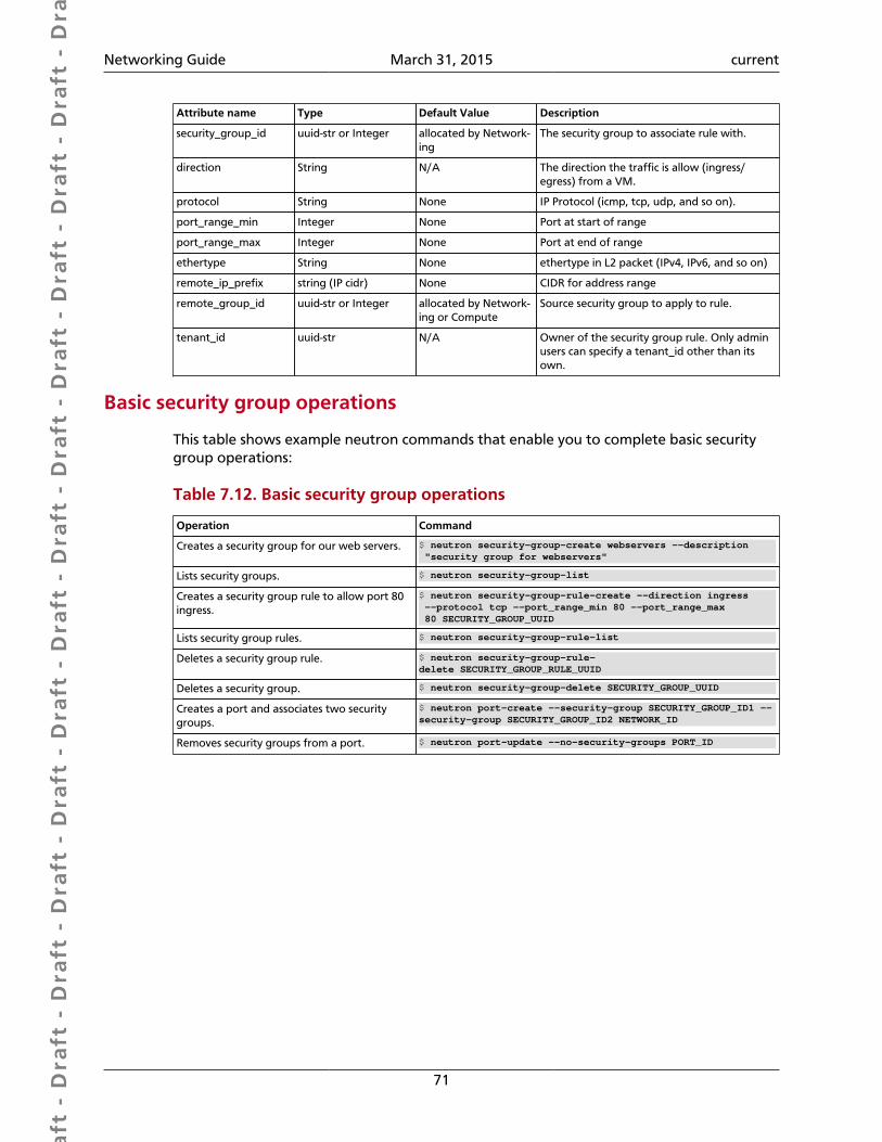
Dra
ft -
Dra
ft -
Dra
ft -
Dra
ft -
Dra
ft -
Dra
ft -
Dra
ft -
Dra
ft -
Dra
ft -
Dra
ft -
Dra
ft -
Dra
ft -
Dra
ft -
Dra
ft -
Dra
ft -
Dra
ft -
Dra
ft -
Dra
ft -
Dra
ft -
Dra
ft -
Dra
ft -
Dra
ft -
Dra
ft -
Dra
ft -
Dra
ft -
Dra
ft -
Dra
ft -
Dra
ft -
Dra
ft -
Dra
ft -
Dra
ft -
Dra
ft -
Dra
ft -
Dra
ft -
Dra
ft -
Networking Guide March 31, 2015 current
71
Attribute name Type Default Value Description
security_group_id uuid-str or Integer allocated by Network-ing
The security group to associate rule with.
direction String N/A The direction the traffic is allow (ingress/egress) from a VM.
protocol String None IP Protocol (icmp, tcp, udp, and so on).
port_range_min Integer None Port at start of range
port_range_max Integer None Port at end of range
ethertype String None ethertype in L2 packet (IPv4, IPv6, and so on)
remote_ip_prefix string (IP cidr) None CIDR for address range
remote_group_id uuid-str or Integer allocated by Network-ing or Compute
Source security group to apply to rule.
tenant_id uuid-str N/A Owner of the security group rule. Only adminusers can specify a tenant_id other than itsown.
Basic security group operations
This table shows example neutron commands that enable you to complete basic securitygroup operations:
Table 7.12. Basic security group operations
Operation Command
Creates a security group for our web servers. $ neutron security-group-create webservers --description "security group for webservers"
Lists security groups. $ neutron security-group-list
Creates a security group rule to allow port 80ingress.
$ neutron security-group-rule-create --direction ingress --protocol tcp --port_range_min 80 --port_range_max 80 SECURITY_GROUP_UUID
Lists security group rules. $ neutron security-group-rule-list
Deletes a security group rule. $ neutron security-group-rule-delete SECURITY_GROUP_RULE_UUID
Deletes a security group. $ neutron security-group-delete SECURITY_GROUP_UUID
Creates a port and associates two securitygroups.
$ neutron port-create --security-group SECURITY_GROUP_ID1 --security-group SECURITY_GROUP_ID2 NETWORK_ID
Removes security groups from a port. $ neutron port-update --no-security-groups PORT_ID

Dra
ft -
Dra
ft -
Dra
ft -
Dra
ft -
Dra
ft -
Dra
ft -
Dra
ft -
Dra
ft -
Dra
ft -
Dra
ft -
Dra
ft -
Dra
ft -
Dra
ft -
Dra
ft -
Dra
ft -
Dra
ft -
Dra
ft -
Dra
ft -
Dra
ft -
Dra
ft -
Dra
ft -
Dra
ft -
Dra
ft -
Dra
ft -
Dra
ft -
Dra
ft -
Dra
ft -
Dra
ft -
Dra
ft -
Dra
ft -
Dra
ft -
Dra
ft -
Dra
ft -
Dra
ft -
Dra
ft -
Networking Guide March 31, 2015 current
72
Basic Load-Balancer-as-a-Service operations
Note
The Load-Balancer-as-a-Service (LBaaS) API provisions and configures load bal-ancers. The Havana release offers a reference implementation that is based onthe HAProxy software load balancer.
This list shows example neutron commands that enable you to complete basic LBaaS opera-tions:
• Creates a load balancer pool by using specific provider.
--provider is an optional argument. If not used, the pool is created with de-fault provider for LBaaS service. You should configure the default provider in the[service_providers] section of neutron.conf file. If no default provider is speci-fied for LBaaS, the --provider option is required for pool creation.
$ neutron lb-pool-create --lb-method ROUND_ROBIN --name mypool --protocol HTTP --subnet-id SUBNET_UUID --provider PROVIDER_NAME
• Associates two web servers with pool.
$ neutron lb-member-create --address WEBSERVER1_IP --protocol-port 80 mypool$ neutron lb-member-create --address WEBSERVER2_IP --protocol-port 80 mypool
• Creates a health monitor that checks to make sure our instances are still running on thespecified protocol-port.
$ neutron lb-healthmonitor-create --delay 3 --type HTTP --max-retries 3 --timeout 3
• Associates a health monitor with pool.
$ neutron lb-healthmonitor-associate HEALTHMONITOR_UUID mypool
• Creates a virtual IP (VIP) address that, when accessed through the load balancer, directsthe requests to one of the pool members.
$ neutron lb-vip-create --name myvip --protocol-port 80 --protocol HTTP --subnet-id SUBNET_UUID mypool
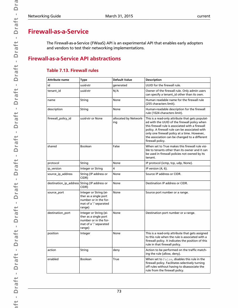
Dra
ft -
Dra
ft -
Dra
ft -
Dra
ft -
Dra
ft -
Dra
ft -
Dra
ft -
Dra
ft -
Dra
ft -
Dra
ft -
Dra
ft -
Dra
ft -
Dra
ft -
Dra
ft -
Dra
ft -
Dra
ft -
Dra
ft -
Dra
ft -
Dra
ft -
Dra
ft -
Dra
ft -
Dra
ft -
Dra
ft -
Dra
ft -
Dra
ft -
Dra
ft -
Dra
ft -
Dra
ft -
Dra
ft -
Dra
ft -
Dra
ft -
Dra
ft -
Dra
ft -
Dra
ft -
Dra
ft -
Networking Guide March 31, 2015 current
73
Firewall-as-a-Service
The Firewall-as-a-Service (FWaaS) API is an experimental API that enables early adoptersand vendors to test their networking implementations.
Firewall-as-a-Service API abstractions
Table 7.13. Firewall rules
Attribute name Type Default Value Description
id uuid-str generated UUID for the firewall rule.
tenant_id uuid-str N/A Owner of the firewall rule. Only admin userscan specify a tenant_id other than its own.
name String None Human readable name for the firewall rule(255 characters limit).
description String None Human-readable description for the firewallrule (1024 characters limit).
firewall_policy_id uuid-str or None allocated by Network-ing
This is a read-only attribute that gets populat-ed with the UUID of the firewall policy whenthis firewall rule is associated with a firewallpolicy. A firewall rule can be associated withonly one firewall policy at a time. However,the association can be changed to a differentfirewall policy.
shared Boolean False When set to True makes this firewall rule visi-ble to tenants other than its owner and it canbe used in firewall policies not owned by itstenant.
protocol String None IP protocol (icmp, tcp, udp, None).
ip_version Integer or String 4 IP version (4, 6).
source_ip_address String (IP address orCIDR)
None Source IP address or CIDR.
destination_ip_address String (IP address orCIDR)
None Destination IP address or CIDR.
source_port Integer or String (ei-ther as a single portnumber or in the for-mat of a ':' separatedrange)
None Source port number or a range.
destination_port Integer or String (ei-ther as a single portnumber or in the for-mat of a ':' separatedrange)
None Destination port number or a range.
position Integer None This is a read-only attribute that gets assignedto this rule when the rule is associated with afirewall policy. It indicates the position of thisrule in that firewall policy.
action String deny Action to be performed on the traffic match-ing the rule (allow, deny).
enabled Boolean True When set to False, disables this rule in thefirewall policy. Facilitates selectively turningoff rules without having to disassociate therule from the firewall policy.
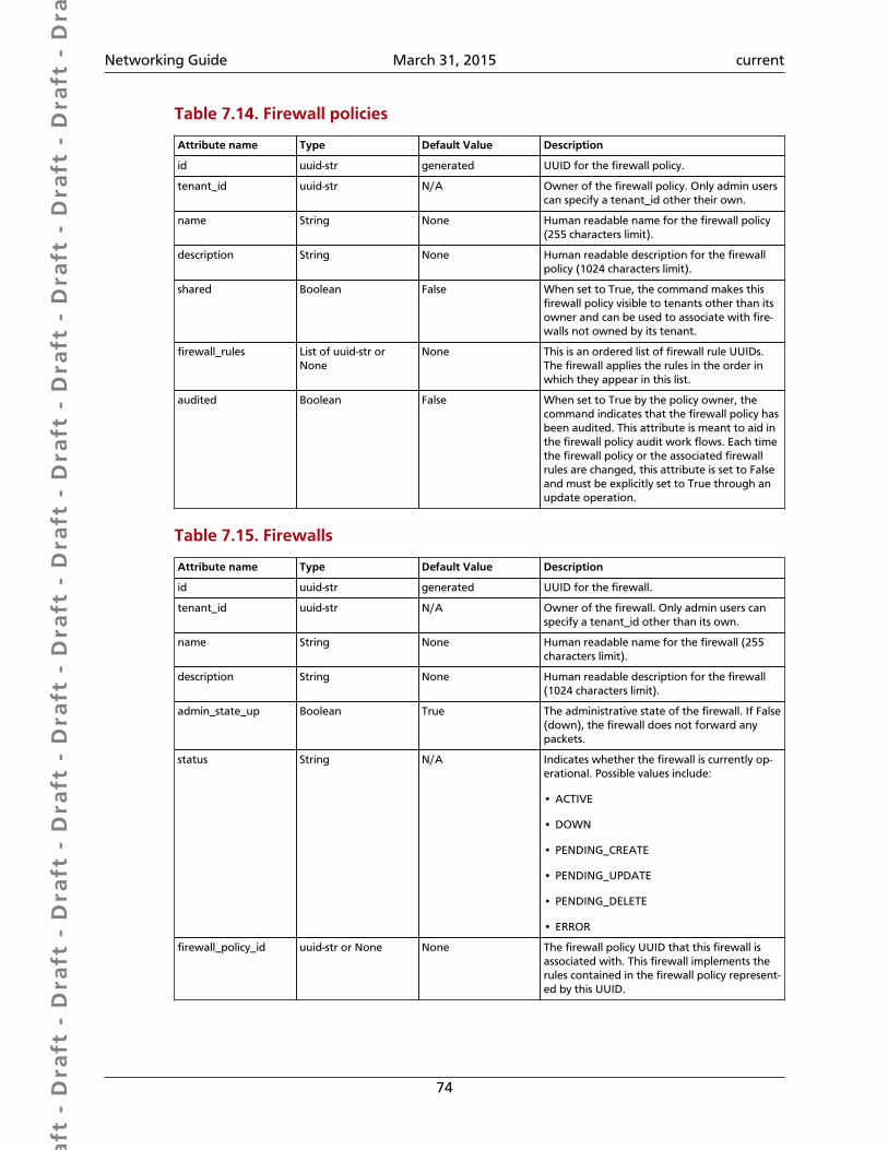
Dra
ft -
Dra
ft -
Dra
ft -
Dra
ft -
Dra
ft -
Dra
ft -
Dra
ft -
Dra
ft -
Dra
ft -
Dra
ft -
Dra
ft -
Dra
ft -
Dra
ft -
Dra
ft -
Dra
ft -
Dra
ft -
Dra
ft -
Dra
ft -
Dra
ft -
Dra
ft -
Dra
ft -
Dra
ft -
Dra
ft -
Dra
ft -
Dra
ft -
Dra
ft -
Dra
ft -
Dra
ft -
Dra
ft -
Dra
ft -
Dra
ft -
Dra
ft -
Dra
ft -
Dra
ft -
Dra
ft -
Networking Guide March 31, 2015 current
74
Table 7.14. Firewall policies
Attribute name Type Default Value Description
id uuid-str generated UUID for the firewall policy.
tenant_id uuid-str N/A Owner of the firewall policy. Only admin userscan specify a tenant_id other their own.
name String None Human readable name for the firewall policy(255 characters limit).
description String None Human readable description for the firewallpolicy (1024 characters limit).
shared Boolean False When set to True, the command makes thisfirewall policy visible to tenants other than itsowner and can be used to associate with fire-walls not owned by its tenant.
firewall_rules List of uuid-str orNone
None This is an ordered list of firewall rule UUIDs.The firewall applies the rules in the order inwhich they appear in this list.
audited Boolean False When set to True by the policy owner, thecommand indicates that the firewall policy hasbeen audited. This attribute is meant to aid inthe firewall policy audit work flows. Each timethe firewall policy or the associated firewallrules are changed, this attribute is set to Falseand must be explicitly set to True through anupdate operation.
Table 7.15. Firewalls
Attribute name Type Default Value Description
id uuid-str generated UUID for the firewall.
tenant_id uuid-str N/A Owner of the firewall. Only admin users canspecify a tenant_id other than its own.
name String None Human readable name for the firewall (255characters limit).
description String None Human readable description for the firewall(1024 characters limit).
admin_state_up Boolean True The administrative state of the firewall. If False(down), the firewall does not forward anypackets.
status String N/A Indicates whether the firewall is currently op-erational. Possible values include:
• ACTIVE
• DOWN
• PENDING_CREATE
• PENDING_UPDATE
• PENDING_DELETE
• ERROR
firewall_policy_id uuid-str or None None The firewall policy UUID that this firewall isassociated with. This firewall implements therules contained in the firewall policy represent-ed by this UUID.
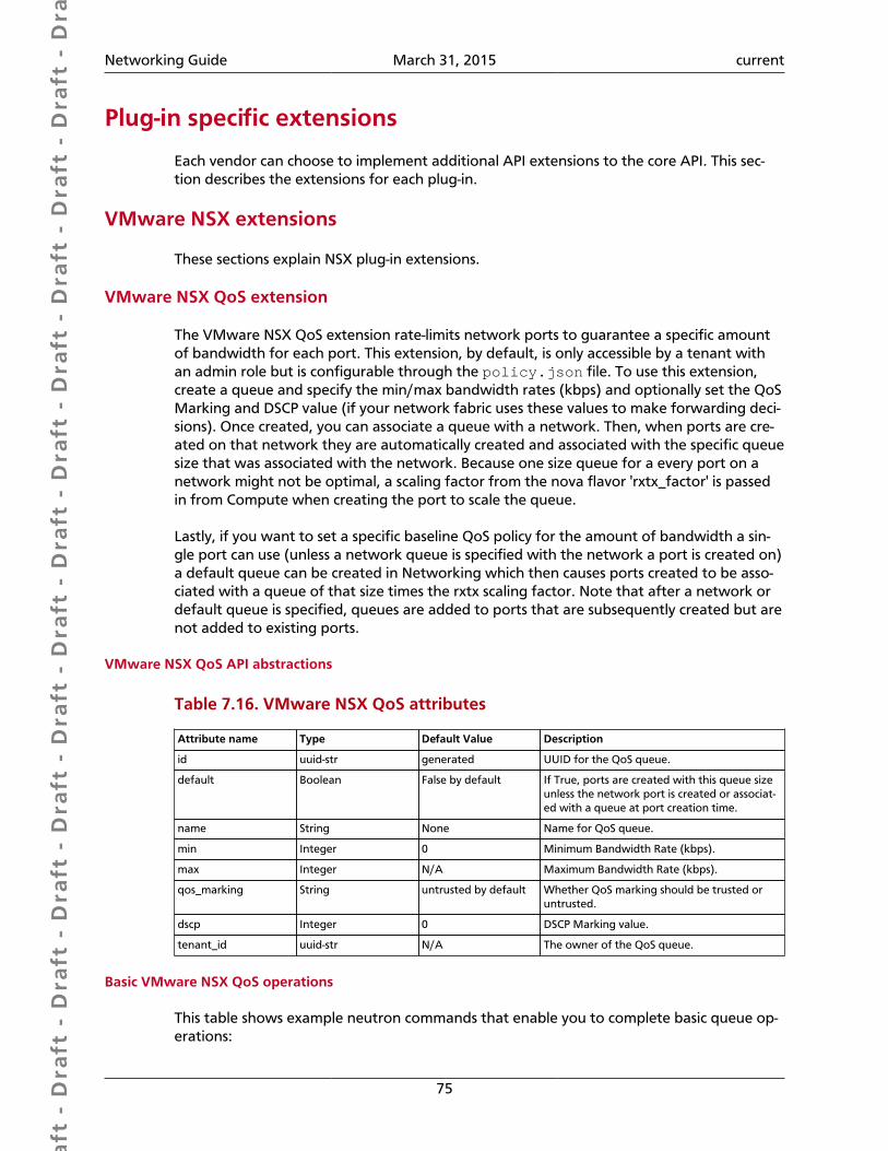
Dra
ft -
Dra
ft -
Dra
ft -
Dra
ft -
Dra
ft -
Dra
ft -
Dra
ft -
Dra
ft -
Dra
ft -
Dra
ft -
Dra
ft -
Dra
ft -
Dra
ft -
Dra
ft -
Dra
ft -
Dra
ft -
Dra
ft -
Dra
ft -
Dra
ft -
Dra
ft -
Dra
ft -
Dra
ft -
Dra
ft -
Dra
ft -
Dra
ft -
Dra
ft -
Dra
ft -
Dra
ft -
Dra
ft -
Dra
ft -
Dra
ft -
Dra
ft -
Dra
ft -
Dra
ft -
Dra
ft -
Networking Guide March 31, 2015 current
75
Plug-in specific extensions
Each vendor can choose to implement additional API extensions to the core API. This sec-tion describes the extensions for each plug-in.
VMware NSX extensions
These sections explain NSX plug-in extensions.
VMware NSX QoS extension
The VMware NSX QoS extension rate-limits network ports to guarantee a specific amountof bandwidth for each port. This extension, by default, is only accessible by a tenant withan admin role but is configurable through the policy.json file. To use this extension,create a queue and specify the min/max bandwidth rates (kbps) and optionally set the QoSMarking and DSCP value (if your network fabric uses these values to make forwarding deci-sions). Once created, you can associate a queue with a network. Then, when ports are cre-ated on that network they are automatically created and associated with the specific queuesize that was associated with the network. Because one size queue for a every port on anetwork might not be optimal, a scaling factor from the nova flavor 'rxtx_factor' is passedin from Compute when creating the port to scale the queue.
Lastly, if you want to set a specific baseline QoS policy for the amount of bandwidth a sin-gle port can use (unless a network queue is specified with the network a port is created on)a default queue can be created in Networking which then causes ports created to be asso-ciated with a queue of that size times the rxtx scaling factor. Note that after a network ordefault queue is specified, queues are added to ports that are subsequently created but arenot added to existing ports.
VMware NSX QoS API abstractions
Table 7.16. VMware NSX QoS attributes
Attribute name Type Default Value Description
id uuid-str generated UUID for the QoS queue.
default Boolean False by default If True, ports are created with this queue sizeunless the network port is created or associat-ed with a queue at port creation time.
name String None Name for QoS queue.
min Integer 0 Minimum Bandwidth Rate (kbps).
max Integer N/A Maximum Bandwidth Rate (kbps).
qos_marking String untrusted by default Whether QoS marking should be trusted oruntrusted.
dscp Integer 0 DSCP Marking value.
tenant_id uuid-str N/A The owner of the QoS queue.
Basic VMware NSX QoS operations
This table shows example neutron commands that enable you to complete basic queue op-erations:
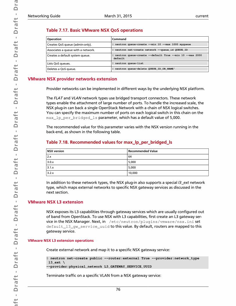
Dra
ft -
Dra
ft -
Dra
ft -
Dra
ft -
Dra
ft -
Dra
ft -
Dra
ft -
Dra
ft -
Dra
ft -
Dra
ft -
Dra
ft -
Dra
ft -
Dra
ft -
Dra
ft -
Dra
ft -
Dra
ft -
Dra
ft -
Dra
ft -
Dra
ft -
Dra
ft -
Dra
ft -
Dra
ft -
Dra
ft -
Dra
ft -
Dra
ft -
Dra
ft -
Dra
ft -
Dra
ft -
Dra
ft -
Dra
ft -
Dra
ft -
Dra
ft -
Dra
ft -
Dra
ft -
Dra
ft -
Networking Guide March 31, 2015 current
76
Table 7.17. Basic VMware NSX QoS operations
Operation Command
Creates QoS queue (admin-only). $ neutron queue-create --min 10 --max 1000 myqueue
Associates a queue with a network. $ neutron net-create network --queue_id QUEUE_ID
Creates a default system queue. $ neutron queue-create --default True --min 10 --max 2000 default
Lists QoS queues. $ neutron queue-list
Deletes a QoS queue. $ neutron queue-delete QUEUE_ID_OR_NAME'
VMware NSX provider networks extension
Provider networks can be implemented in different ways by the underlying NSX platform.
The FLAT and VLAN network types use bridged transport connectors. These networktypes enable the attachment of large number of ports. To handle the increased scale, theNSX plug-in can back a single OpenStack Network with a chain of NSX logical switches.You can specify the maximum number of ports on each logical switch in this chain on themax_lp_per_bridged_ls parameter, which has a default value of 5,000.
The recommended value for this parameter varies with the NSX version running in theback-end, as shown in the following table.
Table 7.18. Recommended values for max_lp_per_bridged_ls
NSX version Recommended Value
2.x 64
3.0.x 5,000
3.1.x 5,000
3.2.x 10,000
In addition to these network types, the NSX plug-in also supports a special l3_ext networktype, which maps external networks to specific NSX gateway services as discussed in thenext section.
VMware NSX L3 extension
NSX exposes its L3 capabilities through gateway services which are usually configured outof band from OpenStack. To use NSX with L3 capabilities, first create an L3 gateway ser-vice in the NSX Manager. Next, in /etc/neutron/plugins/vmware/nsx.ini setdefault_l3_gw_service_uuid to this value. By default, routers are mapped to thisgateway service.
VMware NSX L3 extension operations
Create external network and map it to a specific NSX gateway service:
$ neutron net-create public --router:external True --provider:network_type l3_ext \--provider:physical_network L3_GATEWAY_SERVICE_UUID
Terminate traffic on a specific VLAN from a NSX gateway service:
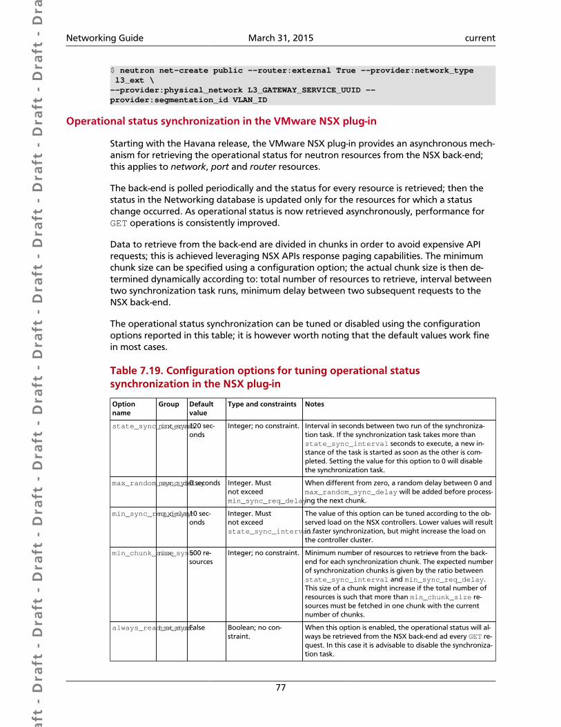
Dra
ft -
Dra
ft -
Dra
ft -
Dra
ft -
Dra
ft -
Dra
ft -
Dra
ft -
Dra
ft -
Dra
ft -
Dra
ft -
Dra
ft -
Dra
ft -
Dra
ft -
Dra
ft -
Dra
ft -
Dra
ft -
Dra
ft -
Dra
ft -
Dra
ft -
Dra
ft -
Dra
ft -
Dra
ft -
Dra
ft -
Dra
ft -
Dra
ft -
Dra
ft -
Dra
ft -
Dra
ft -
Dra
ft -
Dra
ft -
Dra
ft -
Dra
ft -
Dra
ft -
Dra
ft -
Dra
ft -
Networking Guide March 31, 2015 current
77
$ neutron net-create public --router:external True --provider:network_type l3_ext \--provider:physical_network L3_GATEWAY_SERVICE_UUID --provider:segmentation_id VLAN_ID
Operational status synchronization in the VMware NSX plug-in
Starting with the Havana release, the VMware NSX plug-in provides an asynchronous mech-anism for retrieving the operational status for neutron resources from the NSX back-end;this applies to network, port and router resources.
The back-end is polled periodically and the status for every resource is retrieved; then thestatus in the Networking database is updated only for the resources for which a statuschange occurred. As operational status is now retrieved asynchronously, performance forGET operations is consistently improved.
Data to retrieve from the back-end are divided in chunks in order to avoid expensive APIrequests; this is achieved leveraging NSX APIs response paging capabilities. The minimumchunk size can be specified using a configuration option; the actual chunk size is then de-termined dynamically according to: total number of resources to retrieve, interval betweentwo synchronization task runs, minimum delay between two subsequent requests to theNSX back-end.
The operational status synchronization can be tuned or disabled using the configurationoptions reported in this table; it is however worth noting that the default values work finein most cases.
Table 7.19. Configuration options for tuning operational statussynchronization in the NSX plug-in
Optionname
Group Defaultvalue
Type and constraints Notes
state_sync_intervalnsx_sync120 sec-onds
Integer; no constraint. Interval in seconds between two run of the synchroniza-tion task. If the synchronization task takes more thanstate_sync_interval seconds to execute, a new in-stance of the task is started as soon as the other is com-pleted. Setting the value for this option to 0 will disablethe synchronization task.
max_random_sync_delaynsx_sync0 seconds Integer. Mustnot exceedmin_sync_req_delay
When different from zero, a random delay between 0 andmax_random_sync_delay will be added before process-ing the next chunk.
min_sync_req_delaynsx_sync10 sec-onds
Integer. Mustnot exceedstate_sync_interval.
The value of this option can be tuned according to the ob-served load on the NSX controllers. Lower values will resultin faster synchronization, but might increase the load onthe controller cluster.
min_chunk_sizensx_sync500 re-sources
Integer; no constraint. Minimum number of resources to retrieve from the back-end for each synchronization chunk. The expected numberof synchronization chunks is given by the ratio betweenstate_sync_interval and min_sync_req_delay.This size of a chunk might increase if the total number ofresources is such that more than min_chunk_size re-sources must be fetched in one chunk with the currentnumber of chunks.
always_read_statusnsx_syncFalse Boolean; no con-straint.
When this option is enabled, the operational status will al-ways be retrieved from the NSX back-end ad every GET re-quest. In this case it is advisable to disable the synchroniza-tion task.

Dra
ft -
Dra
ft -
Dra
ft -
Dra
ft -
Dra
ft -
Dra
ft -
Dra
ft -
Dra
ft -
Dra
ft -
Dra
ft -
Dra
ft -
Dra
ft -
Dra
ft -
Dra
ft -
Dra
ft -
Dra
ft -
Dra
ft -
Dra
ft -
Dra
ft -
Dra
ft -
Dra
ft -
Dra
ft -
Dra
ft -
Dra
ft -
Dra
ft -
Dra
ft -
Dra
ft -
Dra
ft -
Dra
ft -
Dra
ft -
Dra
ft -
Dra
ft -
Dra
ft -
Dra
ft -
Dra
ft -
Networking Guide March 31, 2015 current
78
When running multiple OpenStack Networking server instances, the status synchronizationtask should not run on every node; doing so sends unnecessary traffic to the NSX back-endand performs unnecessary DB operations. Set the state_sync_interval configurationoption to a non-zero value exclusively on a node designated for back-end status synchro-nization.
The fields=status parameter in Networking API requests always triggers an explicitquery to the NSX back end, even when you enable asynchronous state synchronization. Forexample, GET /v2.0/networks/NET_ID?fields=status&fields=name.
Big Switch plug-in extensions
This section explains the Big Switch neutron plug-in-specific extension.
Big Switch router rules
Big Switch allows router rules to be added to each tenant router. These rules can be usedto enforce routing policies such as denying traffic between subnets or traffic to externalnetworks. By enforcing these at the router level, network segmentation policies can be en-forced across many VMs that have differing security groups.
Router rule attributes
Each tenant router has a set of router rules associated with it. Each router rule has the at-tributes in this table. Router rules and their attributes can be set using the neutron router-update command, through the horizon interface or the Networking API.
Table 7.20. Big Switch Router rule attributes
Attribute name Required Input Type Description
source Yes A valid CIDR or one of thekeywords 'any' or 'external'
The network that a packet's source IP mustmatch for the rule to be applied
destination Yes A valid CIDR or one of thekeywords 'any' or 'external'
The network that a packet's destination IPmust match for the rule to be applied
action Yes 'permit' or 'deny' Determines whether or not the matched pack-ets will allowed to cross the router
nexthop No A plus-separated (+)list of next-hop IP ad-dresses. For example,1.1.1.1+1.1.1.2.
Overrides the default virtual router used tohandle traffic for packets that match the rule
Order of rule processing
The order of router rules has no effect. Overlapping rules are evaluated using longest prefixmatching on the source and destination fields. The source field is matched first so it alwaystakes higher precedence over the destination field. In other words, longest prefix match-ing is used on the destination field only if there are multiple matching rules with the samesource.
Big Switch router rules operations
Router rules are configured with a router update operation in OpenStack Networking. Theupdate overrides any previous rules so all rules must be provided at the same time.
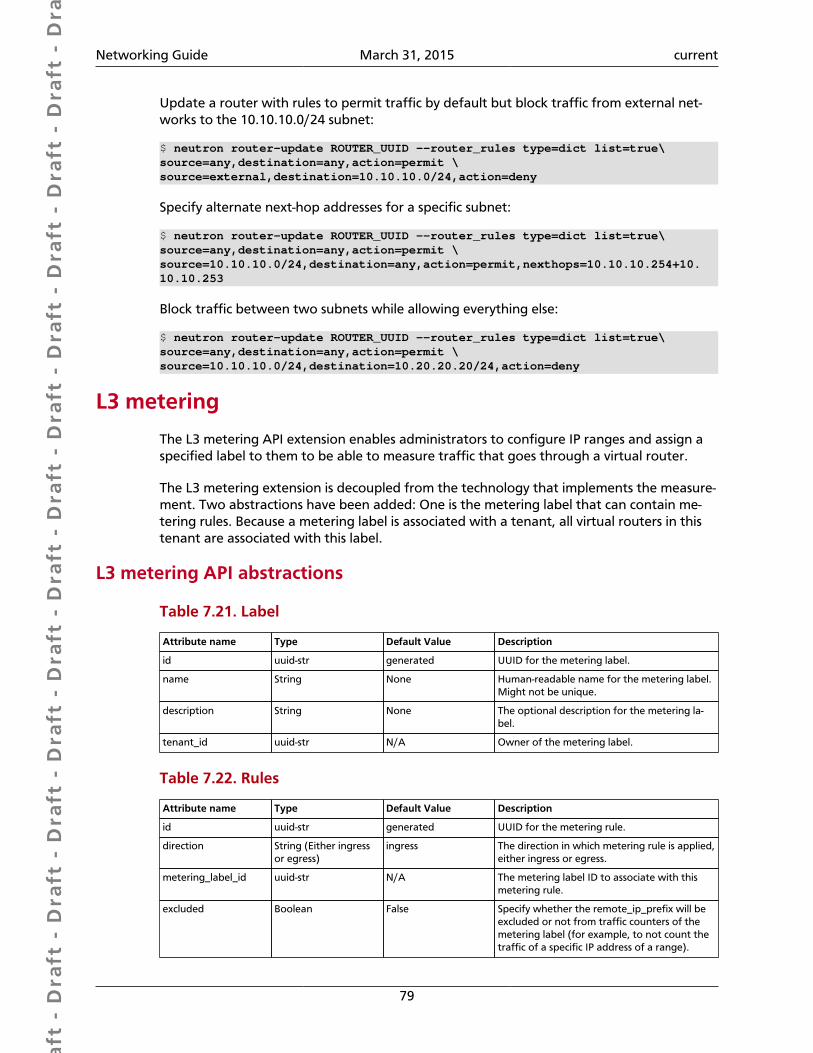
Dra
ft -
Dra
ft -
Dra
ft -
Dra
ft -
Dra
ft -
Dra
ft -
Dra
ft -
Dra
ft -
Dra
ft -
Dra
ft -
Dra
ft -
Dra
ft -
Dra
ft -
Dra
ft -
Dra
ft -
Dra
ft -
Dra
ft -
Dra
ft -
Dra
ft -
Dra
ft -
Dra
ft -
Dra
ft -
Dra
ft -
Dra
ft -
Dra
ft -
Dra
ft -
Dra
ft -
Dra
ft -
Dra
ft -
Dra
ft -
Dra
ft -
Dra
ft -
Dra
ft -
Dra
ft -
Dra
ft -
Networking Guide March 31, 2015 current
79
Update a router with rules to permit traffic by default but block traffic from external net-works to the 10.10.10.0/24 subnet:
$ neutron router-update ROUTER_UUID --router_rules type=dict list=true\source=any,destination=any,action=permit \source=external,destination=10.10.10.0/24,action=deny
Specify alternate next-hop addresses for a specific subnet:
$ neutron router-update ROUTER_UUID --router_rules type=dict list=true\source=any,destination=any,action=permit \source=10.10.10.0/24,destination=any,action=permit,nexthops=10.10.10.254+10.10.10.253
Block traffic between two subnets while allowing everything else:
$ neutron router-update ROUTER_UUID --router_rules type=dict list=true\source=any,destination=any,action=permit \source=10.10.10.0/24,destination=10.20.20.20/24,action=deny
L3 metering
The L3 metering API extension enables administrators to configure IP ranges and assign aspecified label to them to be able to measure traffic that goes through a virtual router.
The L3 metering extension is decoupled from the technology that implements the measure-ment. Two abstractions have been added: One is the metering label that can contain me-tering rules. Because a metering label is associated with a tenant, all virtual routers in thistenant are associated with this label.
L3 metering API abstractions
Table 7.21. Label
Attribute name Type Default Value Description
id uuid-str generated UUID for the metering label.
name String None Human-readable name for the metering label.Might not be unique.
description String None The optional description for the metering la-bel.
tenant_id uuid-str N/A Owner of the metering label.
Table 7.22. Rules
Attribute name Type Default Value Description
id uuid-str generated UUID for the metering rule.
direction String (Either ingressor egress)
ingress The direction in which metering rule is applied,either ingress or egress.
metering_label_id uuid-str N/A The metering label ID to associate with thismetering rule.
excluded Boolean False Specify whether the remote_ip_prefix will beexcluded or not from traffic counters of themetering label (for example, to not count thetraffic of a specific IP address of a range).

Dra
ft -
Dra
ft -
Dra
ft -
Dra
ft -
Dra
ft -
Dra
ft -
Dra
ft -
Dra
ft -
Dra
ft -
Dra
ft -
Dra
ft -
Dra
ft -
Dra
ft -
Dra
ft -
Dra
ft -
Dra
ft -
Dra
ft -
Dra
ft -
Dra
ft -
Dra
ft -
Dra
ft -
Dra
ft -
Dra
ft -
Dra
ft -
Dra
ft -
Dra
ft -
Dra
ft -
Dra
ft -
Dra
ft -
Dra
ft -
Dra
ft -
Dra
ft -
Dra
ft -
Dra
ft -
Dra
ft -
Networking Guide March 31, 2015 current
80
Attribute name Type Default Value Description
remote_ip_prefix String (CIDR) N/A Indicates remote IP prefix to be associatedwith this metering rule.
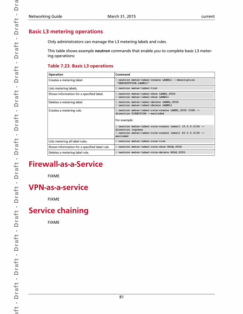
Dra
ft -
Dra
ft -
Dra
ft -
Dra
ft -
Dra
ft -
Dra
ft -
Dra
ft -
Dra
ft -
Dra
ft -
Dra
ft -
Dra
ft -
Dra
ft -
Dra
ft -
Dra
ft -
Dra
ft -
Dra
ft -
Dra
ft -
Dra
ft -
Dra
ft -
Dra
ft -
Dra
ft -
Dra
ft -
Dra
ft -
Dra
ft -
Dra
ft -
Dra
ft -
Dra
ft -
Dra
ft -
Dra
ft -
Dra
ft -
Dra
ft -
Dra
ft -
Dra
ft -
Dra
ft -
Dra
ft -
Networking Guide March 31, 2015 current
81
Basic L3 metering operations
Only administrators can manage the L3 metering labels and rules.
This table shows example neutron commands that enable you to complete basic L3 meter-ing operations:
Table 7.23. Basic L3 operations
Operation Command
Creates a metering label. $ neutron meter-label-create LABEL1 --description "DESCRIPTION_LABEL1"
Lists metering labels. $ neutron meter-label-list
Shows information for a specified label. $ neutron meter-label-show LABEL_UUID$ neutron meter-label-show LABEL1
Deletes a metering label. $ neutron meter-label-delete LABEL_UUID$ neutron meter-label-delete LABEL1
Creates a metering rule. $ neutron meter-label-rule-create LABEL_UUID CIDR --direction DIRECTION --excluded
For example:
$ neutron meter-label-rule-create label1 10.0.0.0/24 --direction ingress$ neutron meter-label-rule-create label1 20.0.0.0/24 --excluded
Lists metering all label rules. $ neutron meter-label-rule-list
Shows information for a specified label rule. $ neutron meter-label-rule-show RULE_UUID
Deletes a metering label rule. $ neutron meter-label-rule-delete RULE_UUID
Firewall-as-a-ServiceFIXME
VPN-as-a-serviceFIXME
Service chainingFIXME
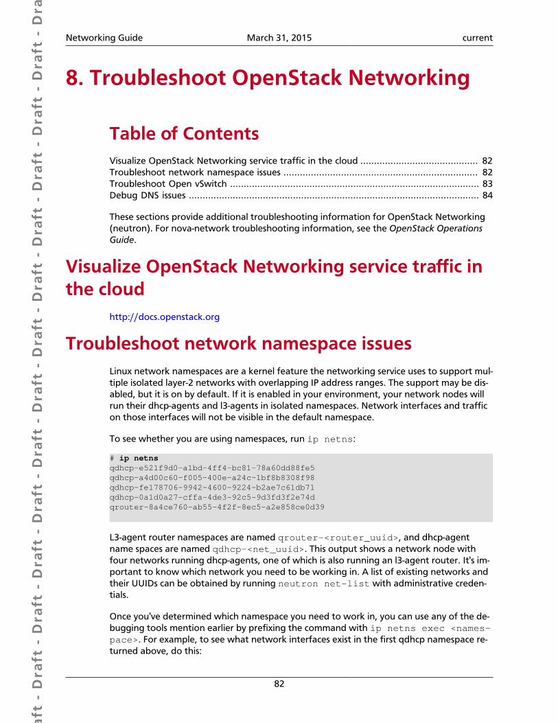
Dra
ft -
Dra
ft -
Dra
ft -
Dra
ft -
Dra
ft -
Dra
ft -
Dra
ft -
Dra
ft -
Dra
ft -
Dra
ft -
Dra
ft -
Dra
ft -
Dra
ft -
Dra
ft -
Dra
ft -
Dra
ft -
Dra
ft -
Dra
ft -
Dra
ft -
Dra
ft -
Dra
ft -
Dra
ft -
Dra
ft -
Dra
ft -
Dra
ft -
Dra
ft -
Dra
ft -
Dra
ft -
Dra
ft -
Dra
ft -
Dra
ft -
Dra
ft -
Dra
ft -
Dra
ft -
Dra
ft -
Networking Guide March 31, 2015 current
82
8. Troubleshoot OpenStack Networking
Table of ContentsVisualize OpenStack Networking service traffic in the cloud ........................................... 82Troubleshoot network namespace issues ....................................................................... 82Troubleshoot Open vSwitch ........................................................................................... 83Debug DNS issues .......................................................................................................... 84
These sections provide additional troubleshooting information for OpenStack Networking(neutron). For nova-network troubleshooting information, see the OpenStack OperationsGuide.
Visualize OpenStack Networking service traffic inthe cloud
http://docs.openstack.org
Troubleshoot network namespace issuesLinux network namespaces are a kernel feature the networking service uses to support mul-tiple isolated layer-2 networks with overlapping IP address ranges. The support may be dis-abled, but it is on by default. If it is enabled in your environment, your network nodes willrun their dhcp-agents and l3-agents in isolated namespaces. Network interfaces and trafficon those interfaces will not be visible in the default namespace.
To see whether you are using namespaces, run ip netns:
# ip netnsqdhcp-e521f9d0-a1bd-4ff4-bc81-78a60dd88fe5qdhcp-a4d00c60-f005-400e-a24c-1bf8b8308f98qdhcp-fe178706-9942-4600-9224-b2ae7c61db71qdhcp-0a1d0a27-cffa-4de3-92c5-9d3fd3f2e74dqrouter-8a4ce760-ab55-4f2f-8ec5-a2e858ce0d39
L3-agent router namespaces are named qrouter-<router_uuid>, and dhcp-agentname spaces are named qdhcp-<net_uuid>. This output shows a network node withfour networks running dhcp-agents, one of which is also running an l3-agent router. It's im-portant to know which network you need to be working in. A list of existing networks andtheir UUIDs can be obtained by running neutron net-list with administrative creden-tials.
Once you've determined which namespace you need to work in, you can use any of the de-bugging tools mention earlier by prefixing the command with ip netns exec <names-pace>. For example, to see what network interfaces exist in the first qdhcp namespace re-turned above, do this:
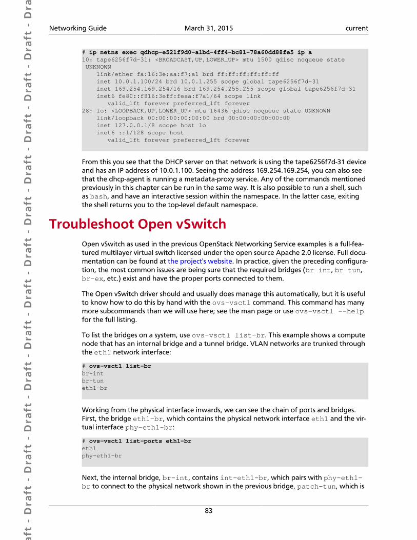
Dra
ft -
Dra
ft -
Dra
ft -
Dra
ft -
Dra
ft -
Dra
ft -
Dra
ft -
Dra
ft -
Dra
ft -
Dra
ft -
Dra
ft -
Dra
ft -
Dra
ft -
Dra
ft -
Dra
ft -
Dra
ft -
Dra
ft -
Dra
ft -
Dra
ft -
Dra
ft -
Dra
ft -
Dra
ft -
Dra
ft -
Dra
ft -
Dra
ft -
Dra
ft -
Dra
ft -
Dra
ft -
Dra
ft -
Dra
ft -
Dra
ft -
Dra
ft -
Dra
ft -
Dra
ft -
Dra
ft -
Networking Guide March 31, 2015 current
83
# ip netns exec qdhcp-e521f9d0-a1bd-4ff4-bc81-78a60dd88fe5 ip a10: tape6256f7d-31: <BROADCAST,UP,LOWER_UP> mtu 1500 qdisc noqueue state UNKNOWN link/ether fa:16:3e:aa:f7:a1 brd ff:ff:ff:ff:ff:ff inet 10.0.1.100/24 brd 10.0.1.255 scope global tape6256f7d-31 inet 169.254.169.254/16 brd 169.254.255.255 scope global tape6256f7d-31 inet6 fe80::f816:3eff:feaa:f7a1/64 scope link valid_lft forever preferred_lft forever28: lo: <LOOPBACK,UP,LOWER_UP> mtu 16436 qdisc noqueue state UNKNOWN link/loopback 00:00:00:00:00:00 brd 00:00:00:00:00:00 inet 127.0.0.1/8 scope host lo inet6 ::1/128 scope host valid_lft forever preferred_lft forever
From this you see that the DHCP server on that network is using the tape6256f7d-31 deviceand has an IP address of 10.0.1.100. Seeing the address 169.254.169.254, you can also seethat the dhcp-agent is running a metadata-proxy service. Any of the commands mentionedpreviously in this chapter can be run in the same way. It is also possible to run a shell, suchas bash, and have an interactive session within the namespace. In the latter case, exitingthe shell returns you to the top-level default namespace.
Troubleshoot Open vSwitchOpen vSwitch as used in the previous OpenStack Networking Service examples is a full-fea-tured multilayer virtual switch licensed under the open source Apache 2.0 license. Full docu-mentation can be found at the project's website. In practice, given the preceding configura-tion, the most common issues are being sure that the required bridges (br-int, br-tun,br-ex, etc.) exist and have the proper ports connected to them.
The Open vSwitch driver should and usually does manage this automatically, but it is usefulto know how to do this by hand with the ovs-vsctl command. This command has manymore subcommands than we will use here; see the man page or use ovs-vsctl --helpfor the full listing.
To list the bridges on a system, use ovs-vsctl list-br. This example shows a computenode that has an internal bridge and a tunnel bridge. VLAN networks are trunked throughthe eth1 network interface:
# ovs-vsctl list-brbr-intbr-tuneth1-br
Working from the physical interface inwards, we can see the chain of ports and bridges.First, the bridge eth1-br, which contains the physical network interface eth1 and the vir-tual interface phy-eth1-br:
# ovs-vsctl list-ports eth1-breth1phy-eth1-br
Next, the internal bridge, br-int, contains int-eth1-br, which pairs with phy-eth1-br to connect to the physical network shown in the previous bridge, patch-tun, which is
Dra
ft -
Dra
ft -
Dra
ft -
Dra
ft -
Dra
ft -
Dra
ft -
Dra
ft -
Dra
ft -
Dra
ft -
Dra
ft -
Dra
ft -
Dra
ft -
Dra
ft -
Dra
ft -
Dra
ft -
Dra
ft -
Dra
ft -
Dra
ft -
Dra
ft -
Dra
ft -
Dra
ft -
Dra
ft -
Dra
ft -
Dra
ft -
Dra
ft -
Dra
ft -
Dra
ft -
Dra
ft -
Dra
ft -
Dra
ft -
Dra
ft -
Dra
ft -
Dra
ft -
Dra
ft -
Dra
ft -
Networking Guide March 31, 2015 current
84
used to connect to the GRE tunnel bridge and the TAP devices that connect to the instancescurrently running on the system:
# ovs-vsctl list-ports br-intint-eth1-brpatch-tuntap2d782834-d1tap690466bc-92tap8a864970-2d
The tunnel bridge, br-tun, contains the patch-int interface and gre-<N> interfaces foreach peer it connects to via GRE, one for each compute and network node in your cluster:
# ovs-vsctl list-ports br-tunpatch-intgre-1...gre-<N>
If any of these links is missing or incorrect, it suggests a configuration error. Bridges can beadded with ovs-vsctl add-br, and ports can be added to bridges with ovs-vsctladd-port. While running these by hand can be useful debugging, it is imperative thatmanual changes that you intend to keep be reflected back into your configuration files.
Debug DNS issuesIf you are able to use SSH to log into an instance, but it takes a very long time (on the orderof a minute) to get a prompt, then you might have a DNS issue. The reason a DNS issue cancause this problem is that the SSH server does a reverse DNS lookup on the IP address thatyou are connecting from. If DNS lookup isn't working on your instances, then you must waitfor the DNS reverse lookup timeout to occur for the SSH login process to complete.
When debugging DNS issues, start by making sure that the host where the dnsmasq pro-cess for that instance runs is able to correctly resolve. If the host cannot resolve, then the in-stances won't be able to either.
A quick way to check whether DNS is working is to resolve a hostname inside your instanceby using the host command. If DNS is working, you should see:
$ host openstack.orgopenstack.org has address 174.143.194.225openstack.org mail is handled by 10 mx1.emailsrvr.com.openstack.org mail is handled by 20 mx2.emailsrvr.com.
If you're running the Cirros image, it doesn't have the "host" program installed, in whichcase you can use ping to try to access a machine by hostname to see whether it resolves. IfDNS is working, the first line of ping would be:
$ ping openstack.orgPING openstack.org (174.143.194.225): 56 data bytes
If the instance fails to resolve the hostname, you have a DNS problem. For example:
Dra
ft -
Dra
ft -
Dra
ft -
Dra
ft -
Dra
ft -
Dra
ft -
Dra
ft -
Dra
ft -
Dra
ft -
Dra
ft -
Dra
ft -
Dra
ft -
Dra
ft -
Dra
ft -
Dra
ft -
Dra
ft -
Dra
ft -
Dra
ft -
Dra
ft -
Dra
ft -
Dra
ft -
Dra
ft -
Dra
ft -
Dra
ft -
Dra
ft -
Dra
ft -
Dra
ft -
Dra
ft -
Dra
ft -
Dra
ft -
Dra
ft -
Dra
ft -
Dra
ft -
Dra
ft -
Dra
ft -
Networking Guide March 31, 2015 current
85
$ ping openstack.orgping: bad address 'openstack.org'
In an OpenStack cloud, the dnsmasq process acts as the DNS server for the instances in ad-dition to acting as the DHCP server. A misbehaving dnsmasq process may be the source ofDNS-related issues inside the instance. As mentioned in the previous section, the simplestway to rule out a misbehaving dnsmasq process is to kill all the dnsmasq processes on themachine and restart nova-network. However, be aware that this command affects every-one running instances on this node, including tenants that have not seen the issue. As a lastresort, as root:
# killall dnsmasq# restart nova-network
After the dnsmasq processes start again, check whether DNS is working.
If restarting the dnsmasq process doesn't fix the issue, you might need to use tcpdump tolook at the packets to trace where the failure is. The DNS server listens on UDP port 53. Youshould see the DNS request on the bridge (such as, br100) of your compute node. Let's sayyou start listening with tcpdump on the compute node:
# tcpdump -i br100 -n -v udp port 53tcpdump: listening on br100, link-type EN10MB (Ethernet), capture size 65535bytes
Then, if you use SSH to log into your instance and try ping openstack.org, you shouldsee something like:
16:36:18.807518 IP (tos 0x0, ttl 64, id 56057, offset 0, flags [DF],proto UDP (17), length 59) 192.168.100.4.54244 > 192.168.100.1.53: 2+ A? openstack.org. (31)16:36:18.808285 IP (tos 0x0, ttl 64, id 0, offset 0, flags [DF],proto UDP (17), length 75) 192.168.100.1.53 > 192.168.100.4.54244: 2 1/0/0 openstack.org. A 174.143.194.225 (47)
Dra
ft -
Dra
ft -
Dra
ft -
Dra
ft -
Dra
ft -
Dra
ft -
Dra
ft -
Dra
ft -
Dra
ft -
Dra
ft -
Dra
ft -
Dra
ft -
Dra
ft -
Dra
ft -
Dra
ft -
Dra
ft -
Dra
ft -
Dra
ft -
Dra
ft -
Dra
ft -
Dra
ft -
Dra
ft -
Dra
ft -
Dra
ft -
Dra
ft -
Dra
ft -
Dra
ft -
Dra
ft -
Dra
ft -
Dra
ft -
Dra
ft -
Dra
ft -
Dra
ft -
Dra
ft -
Dra
ft -
Networking Guide March 31, 2015 current
86
Appendix A. Community support
Table of ContentsDocumentation ............................................................................................................. 86ask.openstack.org .......................................................................................................... 87OpenStack mailing lists .................................................................................................. 87The OpenStack wiki ...................................................................................................... 88The Launchpad Bugs area ............................................................................................. 88The OpenStack IRC channel ........................................................................................... 89Documentation feedback .............................................................................................. 89OpenStack distribution packages ................................................................................... 89
The following resources are available to help you run and use OpenStack. The OpenStackcommunity constantly improves and adds to the main features of OpenStack, but if youhave any questions, do not hesitate to ask. Use the following resources to get OpenStacksupport, and troubleshoot your installations.
DocumentationFor the available OpenStack documentation, see docs.openstack.org.
To provide feedback on documentation, join and use the<[email protected]> mailing list at OpenStack DocumentationMailing List, or report a bug.
The following books explain how to install an OpenStack cloud and its associated compo-nents:
• Installation Guide for openSUSE 13.1 and SUSE Linux Enterprise Server 11 SP3
• Installation Guide for Red Hat Enterprise Linux 7, CentOS 7, and Fedora 20
• Installation Guide for Ubuntu 14.04
The following books explain how to configure and run an OpenStack cloud:
• Architecture Design Guide
• Cloud Administrator Guide
• Configuration Reference
• Operations Guide
• High Availability Guide
• Security Guide
Dra
ft -
Dra
ft -
Dra
ft -
Dra
ft -
Dra
ft -
Dra
ft -
Dra
ft -
Dra
ft -
Dra
ft -
Dra
ft -
Dra
ft -
Dra
ft -
Dra
ft -
Dra
ft -
Dra
ft -
Dra
ft -
Dra
ft -
Dra
ft -
Dra
ft -
Dra
ft -
Dra
ft -
Dra
ft -
Dra
ft -
Dra
ft -
Dra
ft -
Dra
ft -
Dra
ft -
Dra
ft -
Dra
ft -
Dra
ft -
Dra
ft -
Dra
ft -
Dra
ft -
Dra
ft -
Dra
ft -
Networking Guide March 31, 2015 current
87
• Virtual Machine Image Guide
The following books explain how to use the OpenStack dashboard and command-lineclients:
• API Quick Start
• End User Guide
• Admin User Guide
• Command-Line Interface Reference
The following documentation provides reference and guidance information for the Open-Stack APIs:
• OpenStack API Complete Reference (HTML)
• API Complete Reference (PDF)
• OpenStack Block Storage Service API v2 Reference
• OpenStack Compute API v2 and Extensions Reference
• OpenStack Identity Service API v2.0 Reference
• OpenStack Image Service API v2 Reference
• OpenStack Networking API v2.0 Reference
• OpenStack Object Storage API v1 Reference
The Training Guides offer software training for cloud administration and management.
ask.openstack.orgDuring the set up or testing of OpenStack, you might have questions about how a spe-cific task is completed or be in a situation where a feature does not work correctly. Usethe ask.openstack.org site to ask questions and get answers. When you visit the http://ask.openstack.org site, scan the recently asked questions to see whether your question hasalready been answered. If not, ask a new question. Be sure to give a clear, concise summaryin the title and provide as much detail as possible in the description. Paste in your commandoutput or stack traces, links to screen shots, and any other information which might be use-ful.
OpenStack mailing listsA great way to get answers and insights is to post your question or problematic scenarioto the OpenStack mailing list. You can learn from and help others who might have simi-lar issues. To subscribe or view the archives, go to http://lists.openstack.org/cgi-bin/mail-man/listinfo/openstack. You might be interested in the other mailing lists for specificprojects or development, which you can find on the wiki. A description of all mailing lists isavailable at http://wiki.openstack.org/MailingLists.
Dra
ft -
Dra
ft -
Dra
ft -
Dra
ft -
Dra
ft -
Dra
ft -
Dra
ft -
Dra
ft -
Dra
ft -
Dra
ft -
Dra
ft -
Dra
ft -
Dra
ft -
Dra
ft -
Dra
ft -
Dra
ft -
Dra
ft -
Dra
ft -
Dra
ft -
Dra
ft -
Dra
ft -
Dra
ft -
Dra
ft -
Dra
ft -
Dra
ft -
Dra
ft -
Dra
ft -
Dra
ft -
Dra
ft -
Dra
ft -
Dra
ft -
Dra
ft -
Dra
ft -
Dra
ft -
Dra
ft -
Networking Guide March 31, 2015 current
88
The OpenStack wikiThe OpenStack wiki contains a broad range of topics but some of the information can bedifficult to find or is a few pages deep. Fortunately, the wiki search feature enables you tosearch by title or content. If you search for specific information, such as about networkingor nova, you can find a large amount of relevant material. More is being added all the time,so be sure to check back often. You can find the search box in the upper-right corner of anyOpenStack wiki page.
The Launchpad Bugs areaThe OpenStack community values your set up and testing efforts and wants your feedback.To log a bug, you must sign up for a Launchpad account at https://launchpad.net/+login.You can view existing bugs and report bugs in the Launchpad Bugs area. Use the searchfeature to determine whether the bug has already been reported or already been fixed. Ifit still seems like your bug is unreported, fill out a bug report.
Some tips:
• Give a clear, concise summary.
• Provide as much detail as possible in the description. Paste in your command output orstack traces, links to screen shots, and any other information which might be useful.
• Be sure to include the software and package versions that you are using, especially ifyou are using a development branch, such as, "Juno release" vs git commitbc79c3ecc55929bac585d04a03475b72e06a3208.
• Any deployment-specific information is helpful, such as whether you are using Ubuntu14.04 or are performing a multi-node installation.
The following Launchpad Bugs areas are available:
• Bugs: OpenStack Block Storage (cinder)
• Bugs: OpenStack Compute (nova)
• Bugs: OpenStack Dashboard (horizon)
• Bugs: OpenStack Identity (keystone)
• Bugs: OpenStack Image Service (glance)
• Bugs: OpenStack Networking (neutron)
• Bugs: OpenStack Object Storage (swift)
• Bugs: Bare Metal (ironic)
• Bugs: Data Processing Service (sahara)
• Bugs: Database Service (trove)
Dra
ft -
Dra
ft -
Dra
ft -
Dra
ft -
Dra
ft -
Dra
ft -
Dra
ft -
Dra
ft -
Dra
ft -
Dra
ft -
Dra
ft -
Dra
ft -
Dra
ft -
Dra
ft -
Dra
ft -
Dra
ft -
Dra
ft -
Dra
ft -
Dra
ft -
Dra
ft -
Dra
ft -
Dra
ft -
Dra
ft -
Dra
ft -
Dra
ft -
Dra
ft -
Dra
ft -
Dra
ft -
Dra
ft -
Dra
ft -
Dra
ft -
Dra
ft -
Dra
ft -
Dra
ft -
Dra
ft -
Networking Guide March 31, 2015 current
89
• Bugs: Orchestration (heat)
• Bugs: Telemetry (ceilometer)
• Bugs: Queue Service (marconi)
• Bugs: OpenStack API Documentation (developer.openstack.org)
• Bugs: OpenStack Documentation (docs.openstack.org)
The OpenStack IRC channelThe OpenStack community lives in the #openstack IRC channel on the Freenode network.You can hang out, ask questions, or get immediate feedback for urgent and pressing issues.To install an IRC client or use a browser-based client, go to http://webchat.freenode.net/.You can also use Colloquy (Mac OS X, http://colloquy.info/), mIRC (Windows, http://www.mirc.com/), or XChat (Linux). When you are in the IRC channel and want to sharecode or command output, the generally accepted method is to use a Paste Bin. The Open-Stack project has one at http://paste.openstack.org. Just paste your longer amounts of textor logs in the web form and you get a URL that you can paste into the channel. The Open-Stack IRC channel is #openstack on irc.freenode.net. You can find a list of all Open-Stack IRC channels at https://wiki.openstack.org/wiki/IRC.
Documentation feedbackTo provide feedback on documentation, join and use the<[email protected]> mailing list at OpenStack DocumentationMailing List, or report a bug.
OpenStack distribution packagesThe following Linux distributions provide community-supported packages for OpenStack:
• Debian: http://wiki.debian.org/OpenStack
• CentOS, Fedora, and Red Hat Enterprise Linux: http://openstack.redhat.com/
• openSUSE and SUSE Linux Enterprise Server: http://en.opensuse.org/Portal:OpenStack
• Ubuntu: https://wiki.ubuntu.com/ServerTeam/CloudArchive
Dra
ft -
Dra
ft -
Dra
ft -
Dra
ft -
Dra
ft -
Dra
ft -
Dra
ft -
Dra
ft -
Dra
ft -
Dra
ft -
Dra
ft -
Dra
ft -
Dra
ft -
Dra
ft -
Dra
ft -
Dra
ft -
Dra
ft -
Dra
ft -
Dra
ft -
Dra
ft -
Dra
ft -
Dra
ft -
Dra
ft -
Dra
ft -
Dra
ft -
Dra
ft -
Dra
ft -
Dra
ft -
Dra
ft -
Dra
ft -
Dra
ft -
Dra
ft -
Dra
ft -
Dra
ft -
Dra
ft -
Networking Guide March 31, 2015 current
90
GlossaryAPI
Application programming interface.
Block StorageThe OpenStack core project that enables management of volumes, volume snapshots, and volumetypes. The project name of Block Storage is cinder.
ComputeThe OpenStack core project that provides compute services. The project name of Compute serviceis nova.
Database ServiceAn integrated project that provide scalable and reliable Cloud Database-as-a-Service functionalityfor both relational and non-relational database engines. The project name of Database Service istrove.
distributed virtual router (DVR)Mechanism for highly-available multi-host routing when using OpenStack Networking (neutron).
firewallUsed to restrict communications between hosts and/or nodes, implemented in Compute using ipt-ables, arptables, ip6tables, and etables.
IaaSInfrastructure-as-a-Service. IaaS is a provisioning model in which an organization outsources phys-ical components of a data center, such as storage, hardware, servers, and networking compo-nents. A service provider owns the equipment and is responsible for housing, operating and main-taining it. The client typically pays on a per-use basis. IaaS is a model for providing cloud services.
Identity ServiceThe OpenStack core project that provides a central directory of users mapped to the OpenStackservices they can access. It also registers endpoints for OpenStack services. It acts as a common au-thentication system. The project name of the Identity Service is keystone.
Image ServiceAn OpenStack core project that provides discovery, registration, and delivery services for disk andserver images. The project name of the Image Service is glance.
networkA virtual network that provides connectivity between entities. For example, a collection of virtualports that share network connectivity. In Networking terminology, a network is always a layer-2network.
NetworkingA core OpenStack project that provides a network connectivity abstraction layer to OpenStackCompute. The project name of Networking is neutron.
Object StorageThe OpenStack core project that provides eventually consistent and redundant storage and re-trieval of fixed digital content. The project name of OpenStack Object Storage is swift.
Dra
ft -
Dra
ft -
Dra
ft -
Dra
ft -
Dra
ft -
Dra
ft -
Dra
ft -
Dra
ft -
Dra
ft -
Dra
ft -
Dra
ft -
Dra
ft -
Dra
ft -
Dra
ft -
Dra
ft -
Dra
ft -
Dra
ft -
Dra
ft -
Dra
ft -
Dra
ft -
Dra
ft -
Dra
ft -
Dra
ft -
Dra
ft -
Dra
ft -
Dra
ft -
Dra
ft -
Dra
ft -
Dra
ft -
Dra
ft -
Dra
ft -
Dra
ft -
Dra
ft -
Dra
ft -
Dra
ft -
Networking Guide March 31, 2015 current
91
OrchestrationAn integrated project that orchestrates multiple cloud applications for OpenStack. The projectname of Orchestration is heat.
RESTfulA kind of web service API that uses REST, or Representational State Transfer. REST is the style ofarchitecture for hypermedia systems that is used for the World Wide Web.
routerA physical or virtual network device that passes network traffic between different networks.
subnetLogical subdivision of an IP network.
TelemetryAn integrated project that provides metering and measuring facilities for OpenStack. The projectname of Telemetry is ceilometer.
virtual private network (VPN)Provided by Compute in the form of cloudpipes, specialized instances that are used to create VPNson a per-project basis.