Open pre-cabled motor starters Technical Data for
10
Open pre-cabled motor starters A2/19 Technical Data for Designers Open pre-cabled motor starters Contents Non-reversing / Reversing starters ..... A2/20 to A2/23 Star-delta starters ............................... A2/24 to A2/28
Transcript of Open pre-cabled motor starters Technical Data for

Ope
n
pre-
cabl
ed
mot
or
star
ters
A2/19
Technical Data for Designers
Ope
n pr
e-ca
bled
mot
or s
tart
ers
ContentsNon-reversing / Reversing starters ..... A2/20 to A2/23 Star-delta starters ............................... A2/24 to A2/28
A2/20
Ope
n
pre-
cabl
ed
mot
or
star
ters
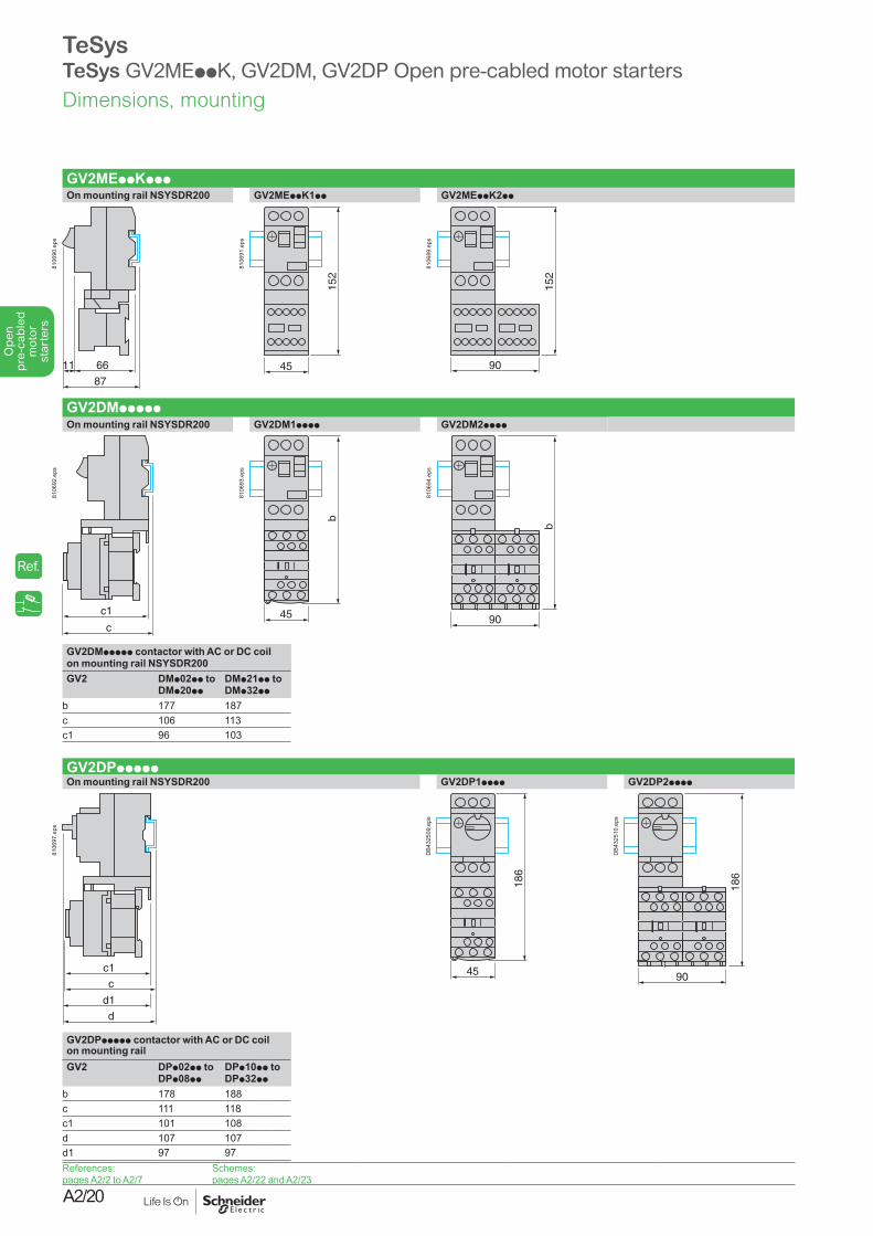
GV2MEppKpppOn mounting rail NSYSDR200 GV2MEppK1pp GV2MEppK2pp
66
87
11
8106
90.e
ps
45
152
8106
91.e
ps
90
152
8106
89.e
ps
GV2DMpppppOn mounting rail NSYSDR200 GV2DM1pppp GV2DM2pppp
c1
c
8106
92.e
ps
45
b
8106
93.e
ps
90
b
8106
94.e
ps
GV2DMppppp contactor with AC or DC coil on mounting rail NSYSDR200GV2 DMp02pp to
DMp20ppDMp21pp to DMp32pp
b 177 187c 106 113c1 96 103
GV2DPpppppOn mounting rail NSYSDR200 GV2DP1pppp GV2DP2pppp
c1
c
d1
d
8106
97.e
ps
45
186
DB4
3250
9.ep
s
90
186
DB4
3251
0.ep
s
GV2DPppppp contactor with AC or DC coil on mounting railGV2 DPp02pp to
DPp08ppDPp10pp to DPp32pp
b 178 188c 111 118c1 101 108d 107 107d1 97 97References:pages A2/2 to A2/7
Schemes:pages A2/22 and A2/23
Dimensions, mounting
TeSysTeSys GV2MEppK, GV2DM, GV2DP Open pre-cabled motor starters
Ref.
A2/21
Ope
n
pre-
cabl
ed
mot
or
star
ters
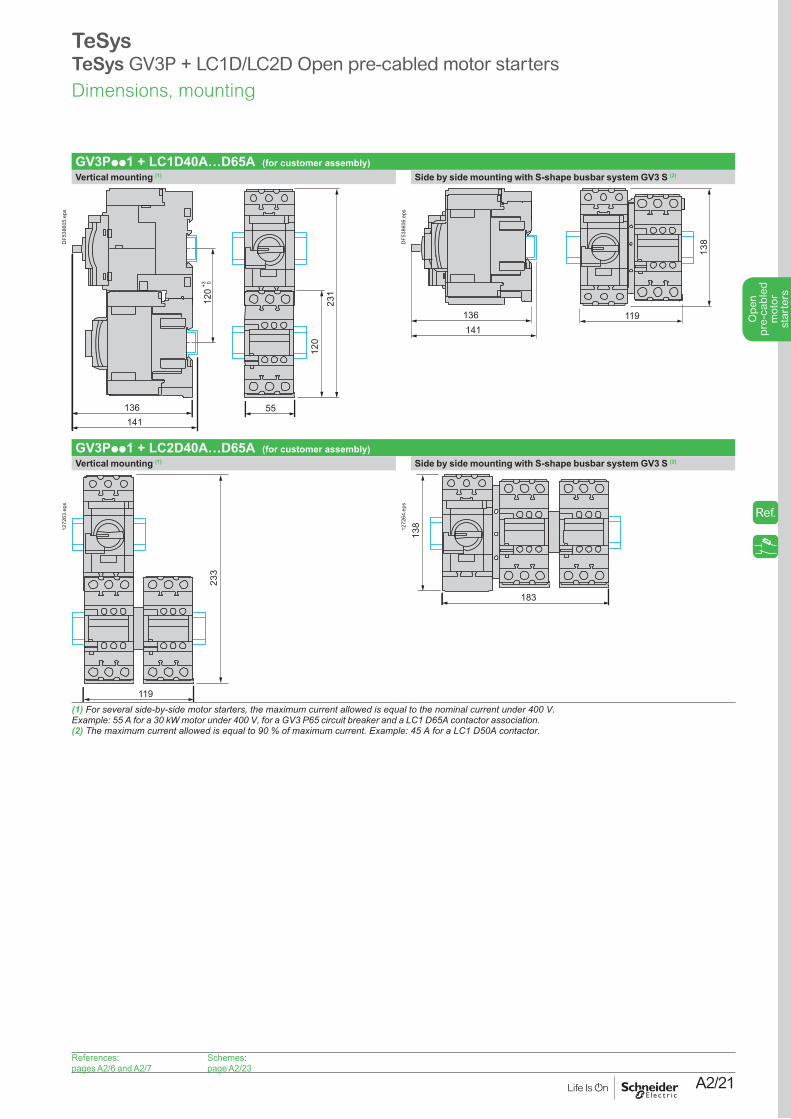
GV3Ppp1 + LC1D40A…D65A (for customer assembly)Vertical mounting (1) Side by side mounting with S-shape busbar system GV3 S (2)
231
120
136 55141
120
+3 0
DF5
3860
5.ep
s
136141
119
138D
F538
606.
eps
GV3Ppp1 + LC2D40A…D65A (for customer assembly)Vertical mounting (1) Side by side mounting with S-shape busbar system GV3 S (2)
233
119
1272
63.e
ps
138
183
1272
64.e
ps
(1) For several side-by-side motor starters, the maximum current allowed is equal to the nominal current under 400 V.Example: 55 A for a 30 kW motor under 400 V, for a GV3 P65 circuit breaker and a LC1 D65A contactor association.(2) The maximum current allowed is equal to 90 % of maximum current. Example: 45 A for a LC1 D50A contactor.
References:pages A2/6 and A2/7
Schemes:page A2/23
Dimensions, mounting
TeSysTeSys GV3P + LC1D/LC2D Open pre-cabled motor starters
Ref.
A2/22
Ope
n
pre-
cabl
ed
mot
or
star
ters
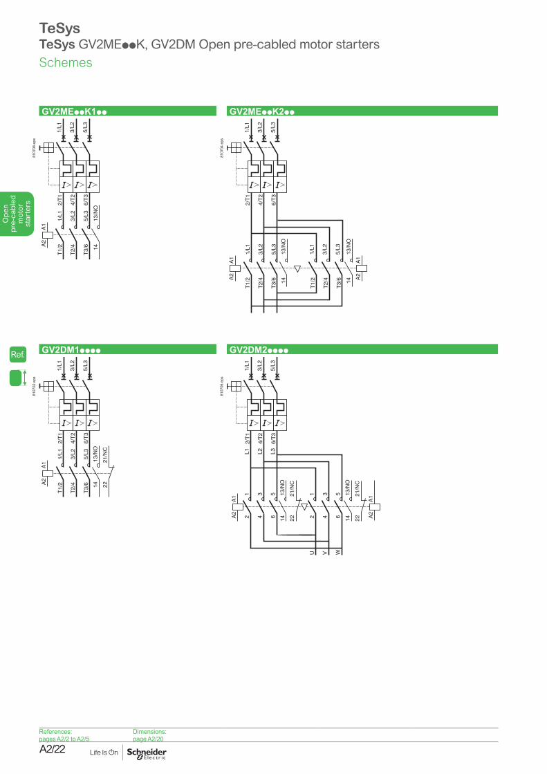
GV2MEppK1pp GV2MEppK2pp
2/T
1
4/T
2
6/T
3
1/L1
3/L2
5/L3
1/L1
3/L2
5/L3
T1/
2
T2/
4
T3/
6
13/N
O14
A1
A2
8107
08.e
ps
2/T
1
4/T
2
6/T
3
1/L1
3/L2
5/L3
1/L1
3/L2
5/L3
T1/
2
T2/
4
T3/
6
13/N
O
T1/
2
T2/
4
T3/
614
13/N
O14
A1
A2
1/L1
3/L2
5/L3
A1
A2
8107
04.e
ps
GV2DM1pppp GV2DM2pppp
2/T
1
4/T
2
6/T
3
1/L1
3/L2
5/L3
1/L1
3/L2
5/L3
T1/
2
T2/
4
T3/
6
A1
A2
1413
/NO
2221
/NC
8107
02.e
ps
2/T
1
4/T
2
6/T
3
1/L1
3/L2
5/L3
14
A1
A2
12
34
56
L1 L2 L3
12
34
56
U V W
13/N
O
1413
/NO
A1
A2
2221
/NC
2221
/NC
GV2DM2••••-SCH-2-M
8107
06.e
ps
References:pages A2/2 to A2/5
Dimensions:page A2/20
Schemes
TeSysTeSys GV2MEppK, GV2DM Open pre-cabled motor starters
Ref.
A2/23
Ope
n
pre-
cabl
ed
mot
or
star
ters
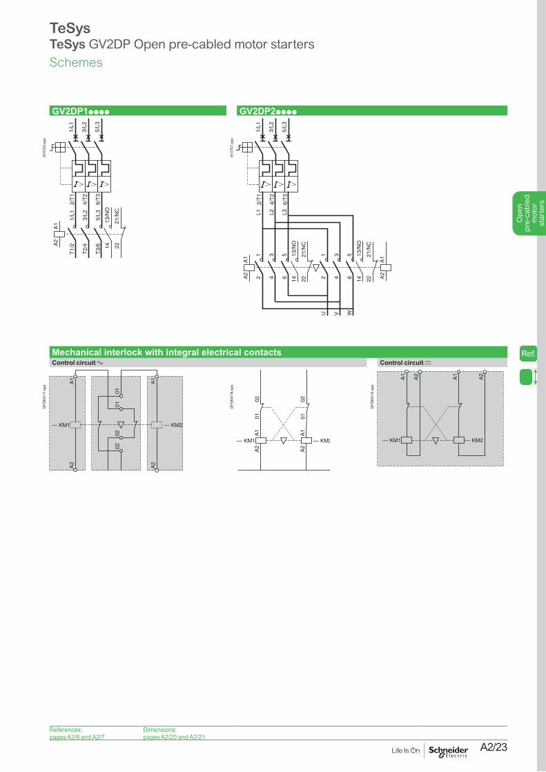
GV2DP1pppp GV2DP2pppp
2/T
1
4/T
2
6/T
3
1/L1
3/L2
5/L3
1/L1
3/L2
5/L3
T1/
2
T2/
4
T3/
6
A1
A2
1413
/NO
2221
/NC
8107
03.e
ps
2/T
1
4/T
2
6/T
3
1/L1
3/L2
5/L3
14
A1
A2
12
34
56
L1 L2 L3
12
34
56
U V W
13/N
O
1413
/NO
A1
A2
2221
/NC
2221
/NC
GV2DP2••••-SCH-2-M
8107
07.e
ps
Mechanical interlock with integral electrical contactsControl circuit a Control circuit c
— KM1
A1
A2
A1
A2
0101
0202
— KM2
DF5
8041
7.ep
s
— KM1
A2
A2
0102 02
— KM2
01
A1
A1
DF5
8041
8.ep
s
— KM1 — KM2
A1
A2
A2
A1
DF5
8041
9.ep
s
References:pages A2/6 and A2/7
Dimensions:pages A2/20 and A2/21
Schemes
TeSysTeSys GV2DP Open pre-cabled motor starters
Ref.
A2/24
Ope
n
pre-
cabl
ed
mot
or
star
ters
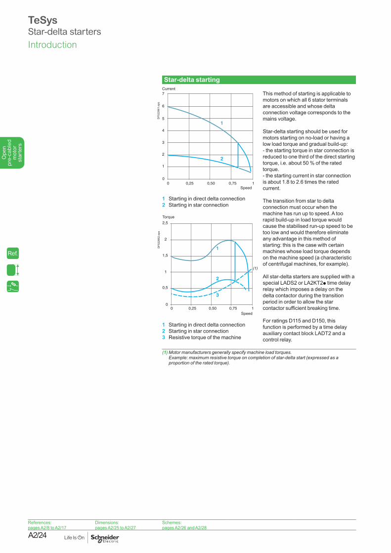
Star-delta starting This method of starting is applicable to motors on which all 6 stator terminals are accessible and whose delta connection voltage corresponds to the mains voltage. Star-delta starting should be used for motors starting on no-load or having a low load torque and gradual build-up: - the starting torque in star connection is reduced to one third of the direct starting torque, i.e. about 50 % of the rated torque. - the starting current in star connection is about 1.8 to 2.6 times the rated current. The transition from star to delta connection must occur when the machine has run up to speed. A too rapid build-up in load torque would cause the stabilised run-up speed to be too low and would therefore eliminate any advantage in this method of starting: this is the case with certain machines whose load torque depends on the machine speed (a characteristic of centrifugal machines, for example). All star-delta starters are supplied with a special LADS2 or LA2KT2p time delay relay which imposes a delay on the delta contactor during the transition period in order to allow the star contactor sufficient breaking time. For ratings D115 and D150, this function is performed by a time delay auxiliary contact block LADT2 and a control relay.
(1) Motor manufacturers generally specify machine load torques. Example: maximum resistive torque on completion of star-delta start (expressed as a proportion of the rated torque).
0
1
2
3
4
5
6
7
0 0,25 0,50 0,75 1
1
2D
F522
661.
eps
Current
Speed
1 Starting in direct delta connection2 Starting in star connection
1 Starting in direct delta connection2 Starting in star connection3 Resistive torque of the machine
Torque
Speed
0
0,5
0 0,25 0,50 0,75 1
1
2
3
(1)1
1,5
2
2,5
DF5
2266
2.ep
s
References:pages A2/8 to A2/17
Dimensions:pages A2/25 to A2/27
Schemes:pages A2/26 and A2/28
Introduction
TeSysStar-delta starters
Ref.
A2/25
Ope
n
pre-
cabl
ed
mot
or
star
ters
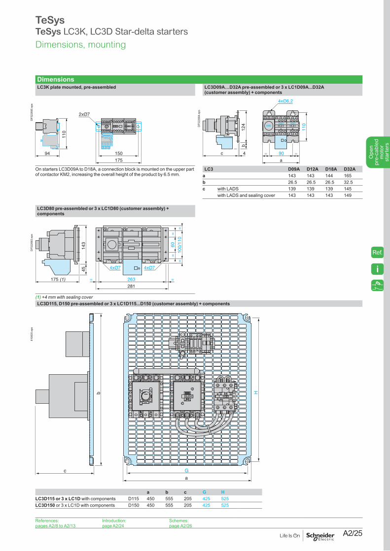
DimensionsLC3K plate mounted, pre-assembled LC3D09A…D32A pre-assembled or 3 x LC1D09A...D32A
(customer assembly) + components
94
110
175
150
DF5
2268
5.ep
s
c 4
124
b
90= =
a
110KM2
KM3 KM1
110DF5
2268
4.ep
s
On starters LC3D09A to D18A, a connection block is mounted on the upper part of contactor KM2, increasing the overall height of the product by 6.5 mm.
LC3 D09A D12A D18A D32Aa 143 143 144 165b 26.5 26.5 26.5 32.5c with LADS 139 139 139 145
with LADS and sealing cover 143 143 143 149
LC3D80 pre-assembled or 3 x LC1D80 (customer assembly) + components
175 (1)
4514
3
263
281
==
60
=10
0/11
0
==
=
DF5
2268
3.ep
s
(1) +4 mm with sealing coverLC3D115, D150 pre-assembled or 3 x LC1D115...D150 (customer assembly) + components
a
G
H
c
b
8108
35.e
ps
References:pages A2/8 to A2/13
Introduction:page A2/24
Schemes:page A2/26
a b c G HLC3D115 or 3 x LC1D with components D115 450 555 205 425 525LC3D150 or 3 x LC1D with components D150 450 555 205 425 525
Dimensions, mounting
TeSysTeSys LC3K, LC3D Star-delta starters
Ref.
i
A2/26
Ope
n
pre-
cabl
ed
mot
or
star
ters
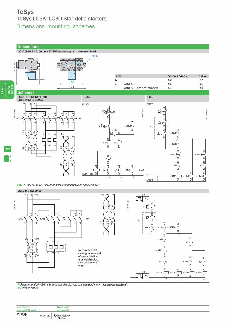
DimensionsLC3D090A à D320A on NSYSDR mounting rail, pre-assembled
c
b
2xØ7
160
175
KM2KM3 KM1
8108
37.e
ps
LC3 D090A à D180A D320Ab 153 137c with LADS 139 145
with LADS and sealing cover 143 149
SchemesLC3K, LC3D09A to D80LC3D090A to D320A
LC3K LC3D
U1
V1
W1
U2
V2
W2
2 4 6
– KM2
12
34
56
– KM3
12
34
56
– KM1
12
34
56
U1
V1
W1
U2
V2
W2
1 3 5
2 4 6
L1 L2 L3
(1)
DB4
2505
0.ep
s
KM2/1 (N)
O
T
T
I
Y
L
KM3/5
– KM3 – KM2– KM1
– KM154 53
A1
A2
A1
A2
A1
A2
A1
A2
– KM1– KM3
2122
2221
1516
9596
– KM2
1413
DF5
1049
0.ep
s
A1
A2
– KM1
1314
2122
2221
– KM3
5556
– KM2
1314
– KM1
9596
KM3/5
O
l
6867
– KM2
A1
A2
– KM3
2221
– KM1
A1
A2
– KM213
14
– KM2
KM3/1
N
(2)
DF5
1048
8.ep
s
Note: LC3D09A to D18A: Mechanical interlock between KM3 and KM1.
LC3D115 and D150
– KM2
12
34
56
– KM3
12
34
56
– KM1
12
34
56
U1
V1 W1
U2
V2 W2
1 3 5
2 4 6
L1 L2 L3
U1
V1 W1
U2
V2 W2
2 4 6
DB4
2505
1.ep
s
Recommended cabling for reversal of motor rotation (standard motor, viewed from shaft end).
A1
A2
– KM1
1314
2122
162
161
– KM3
5556
– KM2
184
183
– KM1
9596
– F1
– F1
O
l
153
154
– KM2
A1
A2
– KA1
A1
A2
– KM2
153
154
– KM1
– F2
171
6768
– KM2
172
– KM1
1314
A1
A2
– KM3
– KA1
Y L
(2)
DB4
1987
7.ep
s
(1) Recommended cabling for reversal of motor rotation (standard motor, viewed from shaft end).(2) Remote control.
References:pages A2/8 to A2/13
Dimensions:page A2/25
Dimensions, mounting, schemes
TeSysTeSys LC3K, LC3D Star-delta starters
Ref.
A2/27
Ope
n
pre-
cabl
ed
mot
or
star
ters
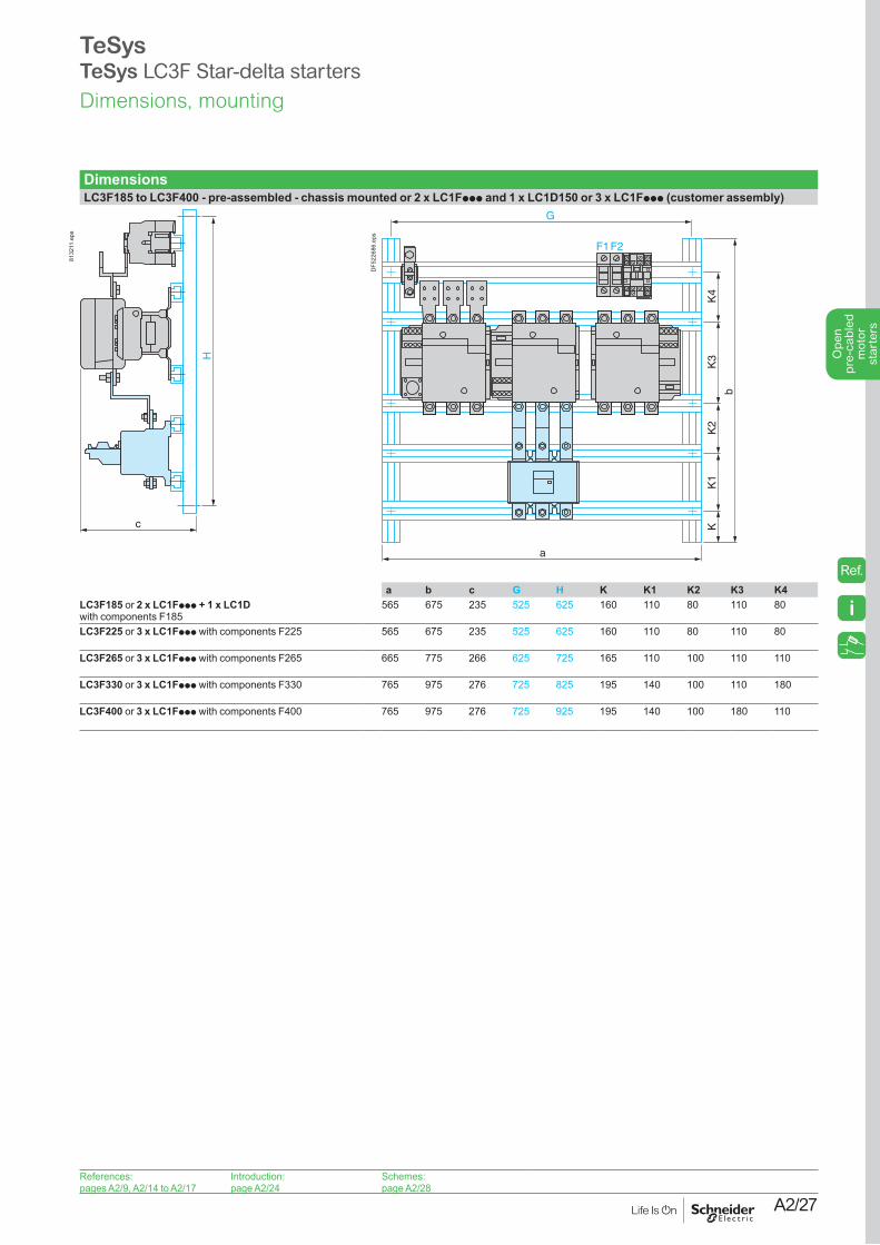
DimensionsLC3F185 to LC3F400 - pre-assembled - chassis mounted or 2 x LC1Fppp and 1 x LC1D150 or 3 x LC1Fppp (customer assembly)
c
H
8132
11.e
ps
KM3KM2 KM1
b
a
G
KK
1K
2K
3K
4
F1F2
DF5
2268
6.ep
s
a b c G H K K1 K2 K3 K4LC3F185 or 2 x LC1Fppp + 1 x LC1D with components F185
565 675 235 525 625 160 110 80 110 80
LC3F225 or 3 x LC1Fppp with components F225 565 675 235 525 625 160 110 80 110 80
LC3F265 or 3 x LC1Fppp with components F265 665 775 266 625 725 165 110 100 110 110
LC3F330 or 3 x LC1Fppp with components F330 765 975 276 725 825 195 140 100 110 180
LC3F400 or 3 x LC1Fppp with components F400 765 975 276 725 925 195 140 100 180 110
References:pages A2/9, A2/14 to A2/17
Introduction:page A2/24
Schemes:page A2/28
Dimensions, mounting
TeSysTeSys LC3F Star-delta starters
i
Ref.
A2/28
Ope
n
pre-
cabl
ed
mot
or
star
ters
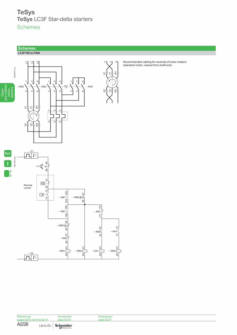
SchemesLC3F185 to F400
– KM2
12
34
56
– KM3
12
34
56
– KM1
12
34
56
U1
V1 W1
U2
V2 W2
1 3 5
2 4 6
L1 L2 L3
U1
V1 W1
U2
V2 W2
2 4 6
DB4
2505
1.ep
s
Recommended cabling for reversal of motor rotation (standard motor, viewed from shaft end).
A1
A2
– KM1
1314
2122
6261
– KM3
5556
– KM2
184
183
– KM1
9596
– F1
– F1
O
l
A1
A2
– KA1
A1
A2
– KM2
153
154
– KM1
– F2
171
6768
– KM2
172
– KM1
1314
A1
A2
– KM3
– KA1
5354
– KM2
Remote control
DB4
1987
8.ep
s
References:pages A2/9, A2/14 to A2/17
Introduction:page A2/24
Dimensions:page A2/27
Schemes
TeSysTeSys LC3F Star-delta starters
i
Ref.