open Design and experimental analysis of dual‑band ...
13
1 Vol.:(0123456789) SCIENTIFIC REPORTS | (2020) 10:15393 | https://doi.org/10.1038/s41598-020-71959-y www.nature.com/scientificreports Design and experimental analysis of dual‑band polarization converting metasurface for microwave applications Bilawal Khan 1 , Babar Kamal 2 , Sadiq Ullah 1* , Imran Khan 3 , Jawad Ali Shah 4* & Jingdong Chen 2 The manipulation of polarization state of electromagnetic waves is of great importance in many practical applications. In this paper, the reflection characteristics of a thin and dual-band metasurface are examined in the microwave frequency regime. The metasurface consists of a 22 × 22 element array of periodic unit cells. The geometry of the unit cell consists of three layers, including a 45° inclined dipole shape metal patch on top, which is backed by a 1.6 mm thick FR-4 substrate in the middle, and a fully reflective metallic mirror at the bottom. The proposed surface is exposed to horizontally (x) or vertically (y) polarized plane waves and the co and cross polarization reflection coefficients of the reflected waves are investigated experimentally in the 6–26 GHz frequency range. The metasurface is designed to convert incident waves of known polarization state (horizontal or vertical) to orthogonal polarization state (vertical and horizontal) in two distinct frequency bands, i.e. 7.1–8 GHz and 13.3–25.8 GHz. In these two frequency bands the simulated and experimental results are in good agreement. The polarization conversion ratio (PCR) of the surface is greater than 95% in the targeted frequency bands. A detailed parametric analysis of the metasurface is also discussed in this work and it has been estimated that the surface has the additional ability to convert linearly polarized waves to circularly polarized waves at several distinct frequencies. The proposed metasurface can be utilized in sensor applications, stealth technology, electromagnetic measurements, and antennas design. Metasurfaces are widely used for polarization control and wave-front shaping of electromagnetic waves in the microwave and optical frequency bands. Polarization is the alignment of electric field component of an elec- tromagnetic wave in space. e manipulation of the polarization of electromagnetic wave in the microwave- to-optical frequency range, has received a great attention, from researchers around the globe due to its diverse applications 1,2 . Applications of polarization manipulative metsurfaces includes, optical vertex converters 2 , optical metrology 3 , quarter 4 and half-wave plates 5 , polarimetry 6 , planar lenses 7 , GPR detection 8 , multi spectral photography 9 , biological sensing 10 and antennas 11 . Polarization can be manipulated either through conventional methods of using natural materials 12 or through artificially engineered materials. Faraday Effect, the optical activity of crystals, proteins with helical secondary structure, gases or solutions of chiral molecules (sugar), and chiral liquid crystals are few of the conventional techniques 12 to control polarization. However, the mentioned converters have the limitation of narrowband frequency response as well as thicker and bulky volume, due to which these converters are inappropriate for use within ultra-thin device sensors and nanophotonic devices. Consequently, artificially engineered materials have been developed for wideband and miniaturized polarization control devices. e most prominent and artificially man-made materials designed for diverse range of micro- wave and optical applications are known as Metamaterials (MMs) 13,14 . ese materials acquired bigger attention because of their fascinating applications such as invisible cloaks 15,16 , negative refraction 17,18 , super diffraction OPEN 1 Department of Telecommunication Engineering, UET Mardan, Mardan 23200, Pakistan. 2 Center of Intelligent Acoustics and Immersive Communications, Northwestern Polytechnical University, Xi’an, Shaanxi, China. 3 Department of Electrical Engineering, UET Mardan, Mardan 23200, Pakistan. 4 Electronic Technology, Universiti Kuala Lumpur, British Malaysian Institute, Selangor, Malaysia. * email: [email protected]; [email protected]
Transcript of open Design and experimental analysis of dual‑band ...

1
Vol.:(0123456789)
Scientific RepoRtS | (2020) 10:15393 | https://doi.org/10.1038/s41598-020-71959-y
www.nature.com/scientificreports
Design and experimental analysis of dual‑band polarization converting metasurface for microwave applicationsBilawal Khan1, Babar Kamal2, Sadiq Ullah1*, imran Khan3, Jawad Ali Shah4* & Jingdong chen2
the manipulation of polarization state of electromagnetic waves is of great importance in many practical applications. In this paper, the reflection characteristics of a thin and dual-band metasurface are examined in the microwave frequency regime. The metasurface consists of a 22 × 22 element array of periodic unit cells. The geometry of the unit cell consists of three layers, including a 45° inclined dipole shape metal patch on top, which is backed by a 1.6 mm thick FR-4 substrate in the middle, and a fully reflective metallic mirror at the bottom. The proposed surface is exposed to horizontally (x) or vertically (y) polarized plane waves and the co and cross polarization reflection coefficients of the reflected waves are investigated experimentally in the 6–26 GHz frequency range. The metasurface is designed to convert incident waves of known polarization state (horizontal or vertical) to orthogonal polarization state (vertical and horizontal) in two distinct frequency bands, i.e. 7.1–8 GHz and 13.3–25.8 GHz. In these two frequency bands the simulated and experimental results are in good agreement. The polarization conversion ratio (PCR) of the surface is greater than 95% in the targeted frequency bands. A detailed parametric analysis of the metasurface is also discussed in this work and it has been estimated that the surface has the additional ability to convert linearly polarized waves to circularly polarized waves at several distinct frequencies. the proposed metasurface can be utilized in sensor applications, stealth technology, electromagnetic measurements, and antennas design.
Metasurfaces are widely used for polarization control and wave-front shaping of electromagnetic waves in the microwave and optical frequency bands. Polarization is the alignment of electric field component of an elec-tromagnetic wave in space. The manipulation of the polarization of electromagnetic wave in the microwave-to-optical frequency range, has received a great attention, from researchers around the globe due to its diverse applications1,2. Applications of polarization manipulative metsurfaces includes, optical vertex converters2, optical metrology3, quarter4 and half-wave plates5, polarimetry6, planar lenses7, GPR detection8, multi spectral photography9, biological sensing10 and antennas11. Polarization can be manipulated either through conventional methods of using natural materials12 or through artificially engineered materials. Faraday Effect, the optical activity of crystals, proteins with helical secondary structure, gases or solutions of chiral molecules (sugar), and chiral liquid crystals are few of the conventional techniques12 to control polarization. However, the mentioned converters have the limitation of narrowband frequency response as well as thicker and bulky volume, due to which these converters are inappropriate for use within ultra-thin device sensors and nanophotonic devices. Consequently, artificially engineered materials have been developed for wideband and miniaturized polarization control devices. The most prominent and artificially man-made materials designed for diverse range of micro-wave and optical applications are known as Metamaterials (MMs)13,14. These materials acquired bigger attention because of their fascinating applications such as invisible cloaks15,16, negative refraction17,18, super diffraction
open
1Department of Telecommunication Engineering, UET Mardan, Mardan 23200, Pakistan. 2Center of Intelligent Acoustics and Immersive Communications, Northwestern Polytechnical University, Xi’an, Shaanxi, China. 3Department of Electrical Engineering, UET Mardan, Mardan 23200, Pakistan. 4Electronic Technology, Universiti Kuala Lumpur, British Malaysian Institute, Selangor, Malaysia. *email: [email protected]; [email protected]

2
Vol:.(1234567890)
Scientific RepoRtS | (2020) 10:15393 | https://doi.org/10.1038/s41598-020-71959-y
www.nature.com/scientificreports/
imaging19,20, fano-resonance21, multi-functional reflectors22, transformation optics23, beam manipulation24,25 and flat lens26, to name but a few.
Metasurfaces27–30 are the two-dimensional equivalent of metamaterials, having the advantage of relaxed fabrication complexity. These metasurfaces can be designed and characterized in two distinct modes, i.e. trans-mission and reflection. A flexible and ultra-thin metasurface (MS) consisting of a single cross placed in a split ring resonator (SRR)31 was used for transmission purposes. The surface was able to achieve half-mirror and quarter-wave plate operation in the microwave region. Similarly, a bi-layer anisotropic metasurface working as a half and quarter wave plate32 was designed using a double SRR on both sides of the substrate with a concentric metallic loop inside. In transmission-mode, higher transmission efficiency can be achieved if the metsurface is thin33. Higher efficiency can be attained if the surface is operated in the reflection mode due to the total reflection of the incoming wave. Recently, several metasurfaces working in the reflection mode have been reported in the literature for polarization conversion in the microwave34–38 and terahertz39 frequency ranges. Two SRRs were proposed on a sub wavelength unit cell structure for multi plasmonic34 resonance in the microwave frequency region. Another anchor shaped metasurface38 was designed using genetic optimization algorithm, which give ultra-wideband polarization conversion bandwidth in five plasmonic resonances. Despite of the many advantages like excellent polarization conversion efficiency, sub-wavelength thickness, wide bandwidth, there is still an issue with polarization converting metasurface; that is dual band, i.e., to convert incident waves of known polarization state to orthogonal polarization state in the microwave frequency range.
In this article, a unique dipole shaped metasurface is realized in the microwave frequency regime, which gives conversion of x-polarized waves to y-polarized waves and vice versa in two distinct frequency bands. It is also estimated that the proposed metasurface has the ability to give linear-to-circular polarization conversion at four distinct frequencies.
Structure design and related theoryDesign of the proposed polarization converting metasurface is shown in Fig. 1a. The upper layer of the unit cell of the metasurface is a leaf-shaped dipole made of copper with a conductivity of 5.8 × 10⁷S/m. The middle layer is FR-4 substrate having dielectric constant, loss tangent, and thickness of 4.4, 0.02 and 1.6 mm, respectively. The bottom layer is a fully reflective copper ground plane. The thickness of the copper patch used in both top and bottom layers is 0.018 mm. The remaining dimensions of the unit cell are labelled in Fig. 1b: i.e., B = 7, I = 7, A = 0.5, W = 1, C = 4.4, L = 1 mm. The angle between the major axis of each elliptical leaf and the dipole is T1 = T2 = 20 degrees.
Figure 1. The proposed metasurface: (a) schematic diagram, (b) angled view of the unit cell, (c) simulation setup (d) top view of the unit cell along u and v coordinate system, (e) picture of the fabricated metasurface, (f) zoomed view of the surface.
3
Vol.:(0123456789)
Scientific RepoRtS | (2020) 10:15393 | https://doi.org/10.1038/s41598-020-71959-y
www.nature.com/scientificreports/
The structure is analyzed and optimized using the Finite Difference Time Domain (FDTD) approach employed in CST Microwave Studio. Periodic boundary conditions have been applied along the x and y direc-tions to simulate and characterize scattering parameters of the periodic array of the unit cell. The structure has been illuminated with linear (x and y) polarized plane waves by assigning a Floquet port at the top of the unit cell. The simulation setup is shown in Fig. 1c. The generalized mathematical representation of the aforemen-tioned x and y polarized incident waves are Exi = ExiexandEyi = Eyiey , where ( ex , ey ) are the unit vectors along the x and y directions, respectively, and the subscript ‘i’ is used for ‘incident’ waves. For a y-polarized incident wave, the reflected waves can be expressed as Er = Exrex + Eyrex = Rxy exp
(
j∅xy)
Eyiex + Ryy exp(
j∅yy)
Eyiey ; where Rxy =
∣
∣Exr/
Eyi∣
∣ and Ryy =∣
∣Eyr/
Eyi∣
∣ , are the cross and co-polarized reflection coefficients, respectively. The former (i.e. Rxy ) gives the fraction of x-polarized component of the reflected wave. The latter (i.e. Ryy ), gives the fraction of the y-polarized component of the reflected wave. The phase angles of the co and cross polariza-tion reflection coefficients are represented by ∅yy and ∅xy , respectively. If an anisotropy is introduced in the unit cell of the metasurface, the relative magnitude and phase of the reflected wave ( Exr and Eyr ) may be different40. Similarly the possibility of conversion of the incident wave from linear to circular wave can occur under special circumstances, i.e., if Rxy = Ryy and �∅ = ∅yy − ∅xy = ±90◦ = 2nπ ± π/2 , where n is an integer. Depending on the frequency, �∅ can take values within the range of − 180° to 180°, showing all possible conversion states (i.e., linear, elliptical and circular.) for the waves upon reflection40,41.
To better comprehend the polarization conversion property of the proposed metasurface, we analyze another parameter called polarization conversion ratio (PCR), which has been used in the literature42–45. The PCR is the ratio of square of the cross-polarization reflection coefficient to the sum of the square of the co and cross polari-zation reflection coefficients. For x-polarization incidence, cross and co-polarized reflection coefficients are Ryx =
EyrExi
and Rxx = ExrExi
, whereas the corresponding coefficients for the y-polarization incident waves are
Rxy =ExrEyi
and Ryy =EyrEyi
, respectively; where the subscripts “i” and “r” represent incident and reflected waves. The PCR can be deduced as follows35:
Results and discussionFrequency response of the reflection coefficient. For experimental validation, the proposed 154*154 mm2 metasurface was fabricated on FR-4 substrate, backed by metallic (copper) ground plane. The number of unit cells accommodated within the area of the fabricated metasurface are 424 (= 22 × 22). The measurement is conducted using the setup shown in Fig. 2. The co and cross polarization reflection coefficients are measured using two ridged broadband (18–26 GHz) horn antennas, both connected to the Agilent N5232A vector net-work analyzer (VNA). One horn act as a transmitting antenna while the other works as a receiving antenna. One horn antenna irradiates the metasurface while the other is used to receive the reflected wave from the metasur-face. The co-polarization reflection coefficients (Rxx, Ryy) are measured by positioning both horn antennas along horizontal or vertical orientation, respectively. To measure the cross-polarization reflection coefficient (Ryx), the receiving antenna was placed in vertical state while the transmitting horn antenna was horizontally positioned. However, for measuring Rxy, the transmitting and receiving horn antennas were employed in vertical and hori-zontal positions, respectively.
The setup was carefully calibrated and the measurements of the metasurface under test were carried out with reference to a metallic (copper) surface. Using the measurement setup in Fig. 2, the radar cross section (RCS) of the metasurface ( σMS ) and the reference copper surface ( σCu ) were measured for an incident wave of known polarization (i.e. x or y). The measured reflection coefficients were extracted by normalizing the measured RCS of the metasurface, relative to the RCS of the reference copper surface. The following expressions were used in the evaluation of the measured reflection coefficients:
where Sr and Si are the power density of the scattered and incident waves, respectively in Wm−2. ρ , is the distance between the horn antennas and the surface under the test. The power density of the scattered and incident waves from the reference copper surface was equal and hence the ratio of Sr to Si is unity and hence the RCS of the copper surface is given by:
The reflection coefficient for a given state of polarization was evaluated by normalizing the RCS of the meta-surface relative to that of the metallic surface, i.e.
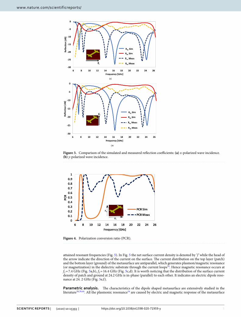
Figure 3a,b illustrate the comparison of the simulated and measured reflection coefficients for x and y polarized wave incidence, respectively. Based on simulated and experimental results, the engineered structure can function as a dual-band polarization conversion device in two distinct frequency bands: 7–8 GHz and 13–25 GHz. The co-polarization reflection coefficients (Rxx and Ryy) are less than − 10 dB in the two frequency
(1)PCR =
∣
∣Ryx∣
∣
2
∣
∣Ryx∣
∣
2+ |Rxx|
2=
∣
∣Rxy∣
∣
2
∣
∣Rxy∣
∣
2+
∣
∣Ryy∣
∣
2
(2)σMS = 4πρ2 Sr
Si
(3)σCu = 4πρ2(1)
(4)Rij =σMS
σCui, j = x or y

4
Vol:.(1234567890)
Scientific RepoRtS | (2020) 10:15393 | https://doi.org/10.1038/s41598-020-71959-y
www.nature.com/scientificreports/
bands, which shows that the reflected waves do not retain the original polarization state of the incident waves. On the other hand, the cross-polarization reflection coefficients (Rxy and Ryx) are predominantly higher (≥ − 3 dB) than their co-polarization counterparts in these frequency bands, which confirms that the polarization state of the incident waves has been transformed into the orthogonal polarization state, after reflection from the proposed metasurface. Except minor differences, the experimental and simulated results are in good agreement. The slight variance in the two is mainly due to the default periodic boundary conditions used in simulations, where an infinite repetition of the unit cells along x and y directions is assumed, which is impossible in the real environ-ment, where we have actually tested a prototype of finite size (22 × 22 unit cells). The finite size of the structure leads to edge diffraction, which results in a slight deviation between the simulated and experimental results. Other reasons that may cause deviation include fabrication tolerances, calibration and human errors involved in fixing the relative angle between the metasurface, transmitting, and receiving antennas.
The phenomenon of polarization conversion is better illustrated by the PCR of the proposed metasurface, which shows the two prominent resonances with excellent measured PCR (> 95%) in the first resonant band and a PCR ~ 60–95% in the second resonant band. The first resonance occurs at 7.4 GHz while the second wideband resonance covers the 13.5 to 25.7 GHz frequency range. In these frequency ranges a linearly polarized incident wave of known polarization state (x or y) is converted to the orthogonally polarized reflected wave (y or x), respectively (Fig. 4). The main reason for the reduction of PCR in the higher resonant band is the lossy nature of the FR-4 substrate at higher frequencies. However, if low loss substrates are used the losses at higher frequen-cies can be minimized.
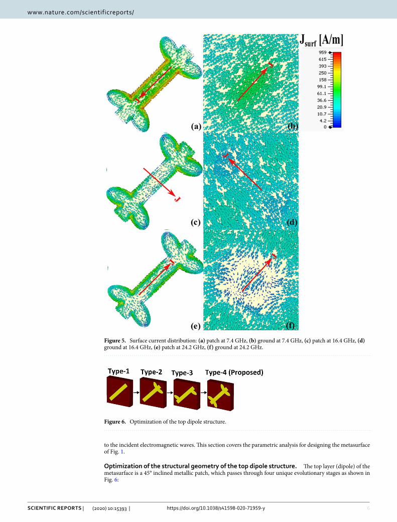
Surface current distribution. The distribution of surface current density on the patch and ground indi-cate the cause of electric or magnetic resonance. For an electric dipole resonance, the distribution of current density on the surface of patch should be in phase (parallel) to the distribution of current on the ground. But when the distribution of current density on the patch is out of phase (anti-parallel) to the distribution of current density on the ground then magnetic resonance will occur. To give more physical insight into the polarization conversion ability of the proposed metasurface, the distribution of surface current density is demonstrated at the
Figure 2. Experimental setup.
5
Vol.:(0123456789)
Scientific RepoRtS | (2020) 10:15393 | https://doi.org/10.1038/s41598-020-71959-y
www.nature.com/scientificreports/
attained resonant frequencies (Fig. 5). In Fig. 5 the net surface current density is denoted by ‘J’ while the head of the arrow indicate the direction of the current on the surface. The current distribution on the top layer (patch) and the bottom layer (ground) of the metasurface are antiparallel, which generates plasmon/magnetic resonance (or magnetization) in the dielectric substrate through the current loops34. Hence magnetic resonance occurs at f1 = 7.4 GHz (Fig. 5a,b), f2 = 16.4 GHz (Fig. 5c,d). It is worth noticing that the distribution of the surface current density of patch and ground at 24.2 GHz is in-phase (parallel) to each other. It indicates an electric dipole reso-nance at 24. 2 GHz (Fig. 5e,f).
parametric analysis. The characteristics of the dipole shaped metasurface are extensively studied in the literature38,39,44. All the plasmonic resonance34 are caused by electric and magnetic response of the metasurface
Figure 3. Comparison of the simulated and measured reflection coefficients: (a) x-polarized wave incidence. (b) y-polarized wave incidence.
Figure 4. Polarization conversion ratio (PCR).
6
Vol:.(1234567890)
Scientific RepoRtS | (2020) 10:15393 | https://doi.org/10.1038/s41598-020-71959-y
www.nature.com/scientificreports/
to the incident electromagnetic waves. This section covers the parametric analysis for designing the metasurface of Fig. 1.
optimization of the structural geometry of the top dipole structure. The top layer (dipole) of the metasurface is a 45° inclined metallic patch, which passes through four unique evolutionary stages as shown in Fig. 6:
Figure 5. Surface current distribution: (a) patch at 7.4 GHz, (b) ground at 7.4 GHz, (c) patch at 16.4 GHz, (d) ground at 16.4 GHz, (e) patch at 24.2 GHz, (f) ground at 24.2 GHz.
Figure 6. Optimization of the top dipole structure.

7
Vol.:(0123456789)
Scientific RepoRtS | (2020) 10:15393 | https://doi.org/10.1038/s41598-020-71959-y
www.nature.com/scientificreports/
Type-1 Simple microstrip.Type-2 Microstrip with two leaf stubs connected to the top-right corner.Type-3 Microstrip with a single leaf stub connected to the top-right and bottom-left corners.Type-4 Proposed microstrip with two leaf stubs connected to the top-right and bottom-left corners.
Initially, each of the metasurface of type-1 to type-4 have been exposed to x-polarized incident to investigate the polarization conversion phenomenon by analyzing the co (Rxx) and cross (Ryx) polarization reflection coef-ficients (Fig. 7). A threshold of Ryx ≥ − 3 dB has been set as a benchmark to define the purity and bandwidth of polarization conversion of the proposed metasurface. It can be clearly noticed that optimization of the dipole structure mainly controls the purity and associated bandwidth of polarization conversion of the metasurface in the upper resonant band (13–25 GHz). The lower resonant band is also shifted due to these design changes. For type-1 a dominant resonance is observed at 10 GHz, where the value of the cross-polarization reflection coefficient (Ryx) is greater than − 3 dB in the lower resonant band (Fig. 7a). The polarization conversion is poor (i.e., Ryx ≤ − 3 dB) in the upper frequency band (17.5–26 GHz). Type-2 gives two dominant resonant bands with Ryx ≥ − 3 dB in the lower (8.5 GHz) and upper (15–18 GHz) frequency bands (Fig. 7b). The polarization conver-sion response of type-3 metasurface is significantly degraded relative to type-1 and 2 (Fig. 7c). The proposed metasurface (type-4) has two prominent polarization conversion bands with a Ryx ≥ − 3 dB, the first narrowband
Figure 7. Comparison of the co- and cross-polarization reflection coefficients by varying the geometry of the dipole structure: (a) type-1, (b) type-2, (c) type-3, (d) type-4, (e) type-4 (y-polarized incident waves).

8
Vol:.(1234567890)
Scientific RepoRtS | (2020) 10:15393 | https://doi.org/10.1038/s41598-020-71959-y
www.nature.com/scientificreports/
resonance covers 7–8 GHz frequency range, while second wideband resonance covers 13.3–25.5 GHz frequency range (Fig. 7d). The introduction of four elliptical shape leaves in type-4 causes the resonance at higher frequency due to the asymmetry of the elliptical leaves attach to the dipole. The proposed resonator supports, two orthogo-nal modes, named as “low mode” and “high mode”. The ‘low mode’ is the transverse magnetic (TM) mode, which is excited in the lower resonant bands (7.4 GHz and 16.4 GHz), and the ‘high mode’ is the transverse electric (TE) mode, excited in the upper resonant band (24. 2 GHz). An identical response has been observed due to the symmetry of the proposed structure for y-polarized incident waves (Fig. 7e). In general, the co-polarization coefficient “Rxx” for the frequency range is lower than − 7 dB, while it reaches to the maximum of − 25 dB at 16 GHz and 24.5 GHz. The cross-polarization coefficient “Ryx” in the frequency range from 13.3 to 25.5 GHz is higher than − 1.6 dB. The PCR in this frequency range is most equal to 1 with a fractional bandwidth of 62%.
For the x-polarized incident wave, the phase difference ( �φ = φxx − φyx ) between the co- and cross-polarized reflected waves is shown in Fig. 8. It is evident from Fig. 7d that the magnitude of the co- and cross-polarization reflection coefficients attain identical values (Ryx = Rxx) at four unique frequencies of 7 GHz, 8.1 GHz, 13.1 GHz and 26 GHz with a phase difference of �∅ = ±90◦ or ±270◦ in these frequency bands (as shown in Fig. 8). Based on these findings it can be estimated that the reflected wave at these four frequencies is circularly polar-ized. In other words, the proposed metasurface has the ability to convert a linearly polarized incident wave into a circular polarized reflected wave of specific handedness. At 7 GHz, Rxx = Ryx and the phase difference (Δϕ) at this frequency is equal to + 90° (i.e., x-polarized component of the reflected wave is 90° ahead of the y-polarized counterpart), which show that the resultant reflected wave is left-hand circularly polarized (LHCP). For the frequencies of 8.1, 13.1 and 26 GHz, the phase difference (Δϕ) is equal to −90° or 270°. The magnitude of the co and cross-polarization reflection are also equal in these bands. The phase difference of − 90° or 270° can lead to a right-hand circularly polarized (RHCP) reflected wave.
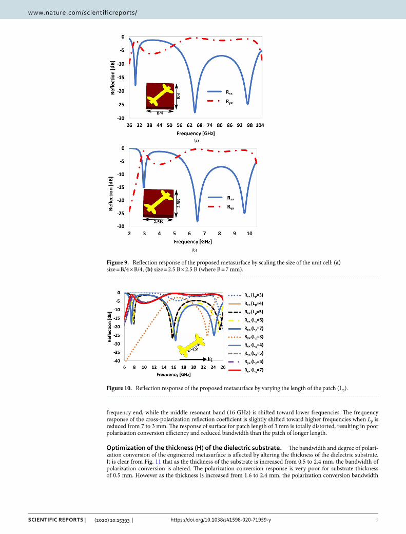
Optimization of size (length × width) of the unit cell of the proposed metasurface. In this sec-tion, the reflection response of the proposed metasurface is investigated by scaling the size (length × width) of the unit cell. As discussed in the previous section, the unit cell of the proposed metasurface of Fig. 1 has a length and width both equal, i.e. B = 7 mm. When it was excited with waves of known polarization, the metasurface generates three resonant frequencies at which the co-polarization reflection coefficient is minimum and the cross-polarization coefficient is maximum. These resonant frequencies are f = 7.4 GHz, 16.4 GHz and 24.2 GHz, as shown in Fig. 7d,e.
When the size of the unit cell is reduced to one quarter (i.e., size = B/4 × B/4), the collective load capacity of the unit cell is reduced and a proportional increase in the resonant frequency occurs as shown in Fig. 9a. Alter-natively, when the size of the unit cell is downscaled by a factor of 4, the resonant frequencies of the original cell (i.e. 7. 4, 16. 4 and 24. 2 GHz), were increased by a factor of four, to 29 GHz, 65 GHz and 97 GHz, respectively. Similarly, when the size of the unit cell is scaled up to 2.5B × 2.5B, the load capacity of the structure has been raised, which results in a proportional decrease in the frequency response of reflection coefficient as depicted in Fig. 9b, i.e., f = 3 GHz, 6.5 GHz and 9.6 GHz. It is worth mentioning that the shape of the frequency response of the reflection coefficient remain unchanged irrespective of upscaling or downscaling the size of the unit cell. It is worth mentioning that the electromagnetic boundary conditions were kept identical for the original unit cell and its scaled counterparts. The simulation frequency sweep for the scaled or transformed versions of the metasurface unit cells have been carefully selected based on the inverse relationship between size of the cell under test and the frequency.
Optimization of the length (Lp) of the dipole structure. To further explore the design, we illustrate the response of the unit cell by changing the length (Lp) of the dipole patch. For x-polarized incident waves, the co- and cross-polarization coefficients are analyzed by changing the length (Lp) from 3 to 7 mm (Fig. 10). It can be seen from Fig. 10 that as the length of the patch decreases (from 7 to 3 mm) the co-polarization reflec-tion coefficient (Rxx) in the lower (7 GHz) and higher (24 GHz) resonant bands is shifted towards the higher
Figure 8. Reflection phase analysis of the proposed metasurface for x-polarized incident waves.
9
Vol.:(0123456789)
Scientific RepoRtS | (2020) 10:15393 | https://doi.org/10.1038/s41598-020-71959-y
www.nature.com/scientificreports/
frequency end, while the middle resonant band (16 GHz) is shifted toward lower frequencies. The frequency response of the cross-polarization reflection coefficient is slightly shifted toward higher frequencies when Lp is reduced from 7 to 3 mm. The response of surface for patch length of 3 mm is totally distorted, resulting in poor polarization conversion efficiency and reduced bandwidth than the patch of longer length.
Optimization of the thickness (H) of the dielectric substrate. The bandwidth and degree of polari-zation conversion of the engineered metasurface is affected by altering the thickness of the dielectric substrate. It is clear from Fig. 11 that as the thickness of the substrate is increased from 0.5 to 2.4 mm, the bandwidth of polarization conversion is altered. The polarization conversion response is very poor for substrate thickness of 0.5 mm. However as the thickness is increased from 1.6 to 2.4 mm, the polarization conversion bandwidth
Figure 9. Reflection response of the proposed metasurface by scaling the size of the unit cell: (a) size = B/4 × B/4, (b) size = 2.5 B × 2.5 B (where B = 7 mm).
Figure 10. Reflection response of the proposed metasurface by varying the length of the patch (Lp).

10
Vol:.(1234567890)
Scientific RepoRtS | (2020) 10:15393 | https://doi.org/10.1038/s41598-020-71959-y
www.nature.com/scientificreports/
gets expanded (17.47 GHz) and the three resonant frequencies of Rxx (f1 = 7.4, f2 = 16.4 and f3 = 24.2 GHz) are shifted downwards (to f1 = 6.5 GHz, f2 = 12 GHz and f3 = 18.5 GHz. This is due to the fact that as the substrate gets thicker, the effective inductance of the unit cell is increased. However, by increasing the thickness of the substrate beyond certain range, the design not only become bulkier in volume but also the performance of the metasurface degrades due to the surface wave losses in thicker substrates. Thus, in designing a polarization converter, perfor-mance, volume and fabrication complexities of the metasurface must be taken into consideration.
parametric extraction. The effective permittivity, effective permeability, effective impedance of the pro-posed design is extracted by S-parameter-retrieval method46–48 as shown in Fig. 12. The following expressions were employed to extract these intrinsic parameters of the metasurface:
where z, S11, S21, are the normalized impedance, reflection coefficient and transmission coefficient, respectively. Likewise, n is the refractive index, ko is the wave number and H is the thickness of the substrate. The effective permittivity, εeff and effective permeability, µeff are evaluated using (7) and (8), respectively.
It is observed that the extracted real and imaginary parts of the retrieved permittivity and permeability at three resonance frequencies of 7.4, 16. 4 and 24.2 GHz are nearly equal. This satisfy the condition of impedance matching of the medium (proposed surface) with the free space resulting in minimum co-polarization reflection and maximum PCR of the surface49. The retrieved effective parameters are listed in Table. 1.
conclusionsWe have simulated and fabricated a thin, dual-band polarization conversion metasurface in the microwave frequency range. The metasurface converts incident waves of known linear polarization state (x or y) to the orthogonal or cross linear polarization state (y and x) in the reflection mode. This polarization conversion has been attained in two distinct frequency bands, i.e., a narrowband ranging from 7.1 GHz to 8 GHz with a PCR > 95% and a wideband ranging from 13.3 GHz to 25.8 GHz, with a PCR ~ 60–95%. Also, at four distinct frequencies, linear polarized wave can be converted into circular polarized wave at 7, 8.1, 13.1, and 26.2 GHz. The intrinsic parameters of the metasurface were retrieved using the S-parameter extraction method, and the values of permittivity and permeability were found nearly equal at the three resonant frequencies (7. 4 GHz, 16.2 GHz and 24. 2 GHz) which supports the argument of polarization convertion in the targeted frequency bands. The proposed metasurface should have great potential in sensor application, stealth technology, electromagnetic measurements, and antenna design because of its ultra-wideband, highly efficient and dual band performance.
(5)z = ±
√
(1+ S11)2 − S221
(1− S11)2 − S221
(6)ejnk0H =S21
1− S11z−1z+1
(7)εeff =n
z
(8)µeff = n× z
Figure 11. Reflection response of the proposed metasurface by varying the thickness of the substrate.

11
Vol.:(0123456789)
Scientific RepoRtS | (2020) 10:15393 | https://doi.org/10.1038/s41598-020-71959-y
www.nature.com/scientificreports/
Figure 12. Extracted parameters of the metasurface (a) real components of εeff, and µeff (b) imaginary components of εeff, and µeff and (c) impedance of the metasurface.
Table 1. Extracted parameters of the proposed metasurface.
Frequency (GHz)
Permittivity (εeff) Permeability (μeff) Impedance (z)
Re (εeff) Im (εeff) Re (μeff) Im (μeff) Re (z) Im (z)
7.4 7.591 1.680 7.827 − 0.585 1.1 − 0.15
16.4 0.810 0.019 0.885 0.177 1.05 0.09
24.2 − 2.618 0.318 − 2.639 − 0.070 0.98 0.07
12
Vol:.(1234567890)
Scientific RepoRtS | (2020) 10:15393 | https://doi.org/10.1038/s41598-020-71959-y
www.nature.com/scientificreports/
Received: 16 December 2019; Accepted: 11 August 2020
References 1. Chen, H. T., Taylor, A. J. & Yu, N. A review of metasurfaces: physics and applications. Rep. Progr. Phys. 79, 076401 (2016). 2. Hsiao, H. H., Chu, C. H. & Tsai, D. P. Fundamentals and applications of metasurfaces. Small Methods 1, 1600064 (2017). 3. Li, J. et al. Simultaneous control of light polarization and phase distributions using plasmonic metasurfaces. Adv. Funct. Mater.
25, 704–710 (2015). 4. Yu, N. et al. A broadband, background-free quarter-wave plate based on plasmonic metasurfaces. Nano Lett. 12, 6328–6333 (2012). 5. Zhang, X., Kong, D., Yuan, Y., Mei, S. & Wang, G. Broadband and dispersion-free reflective silver metasurfaces as half-wave plate
and vortex-beam generator. Opt. Commun. 465, 125561 (2020). 6. Wen, D. et al. Metasurface for characterization of the polarization state of light. Opt. Expr. 23, 10272–10281 (2015). 7. Liu, Y. Q., Che, Y., Qi, K., Li, L. & Yin, H. Design and demonstration of a wide-angle and high-efficient planar metasurface lens.
Opt. Comm. 474, 126061 (2020). 8. Hao, T., Zheng, W., He, W. & Lin, K. Air-ground impedance matching by depositing metasurfaces for enhanced GPR detection.
IEEE Trans. Geosci. Rem. Sens. 58, 4061–4075 (2020). 9. Xiang, M. et al. All-dielectric meta-surface for multispectral photography by theta modulation. Nanomaterials 10, 369 (2020). 10. Heydari, S., Bazgir, M., Zarrabi, F. B., Gandji, N. P. & Rastan, I. Novel optical polarizer design based on metasurface nano aperture
for biological sensing in mid-infrared regime. Opt. Quantum Electron. 49, 83 (2017). 11. Ullah, S., Flint, J. A. & Seager, R. D. Polarisation-dependent electromagnetic bandgap incorporating a slanted sheet via. IET Microw.
Ant. Prop. 5, 519–527 (2011). 12. Bea, S. & Teich, M. C. Fundamentals of Photonics 313 (Wiley, New York, 1991). 13. Zheludev, N. I. & Kivshar, Y. S. From metamaterials to metadevices. Nat. Mater. 11, 917–924 (2012). 14. Holloway, C. L. et al. An overview of the theory and applications of metasurfaces: the two-dimensional equivalents of metamateri-
als. IEEE Ant. Prop. Mag. 54, 10–35 (2012). 15. Schurig, D. et al. Metamaterial electromagnetic cloak at microwave frequencies. Science 314, 977–980 (2006). 16. Ergin, T., Stenger, N., Brenner, P., Pendry, J. B. & Wegener, M. Three-dimensional invisibility cloak at optical wavelengths. Science
328, 337–339 (2010). 17. Shelby, R. A., Smith, D. R. & Schultz, S. Experimental verification of a negative index of refraction. Science 292, 77–79 (2001). 18. Xu, T., Agrawal, A., Abashin, M., Chau, K. J. & Lezec, H. J. All-angle negative refraction and active flat lensing of ultraviolet light.
Nature 497, 470–474 (2013). 19. Luo, X. & Ishihara, T. Surface plasmon resonant interference nanolithography technique. Appl. Phys. Lett. 84, 4780–4782 (2004). 20. Fang, N., Lee, H., Sun, C. & Zhang, X. Sub–diffraction-limited optical imaging with a silver superlens. Science 308, 534–537 (2005). 21. Luk’yanchuk, B. et al. The Fano resonance in plasmonic nanostructures and metamaterials. Nat. Mater. 9, 707–715 (2010). 22. Huang, C., Pan, W., Ma, X. & Luo, X. Multi-spectral metasurface for different functional control of reflection waves. Sci. Rep. 6,
1–7 (2016). 23. Pendry, J. B., Schurig, D. & Smith, D. R. Controlling electromagnetic fields. Science 312, 1780–1782 (2006). 24. Kundtz, N. & Smith, D. R. Extreme-angle broadband metamaterial lens. Nat. Mater. 9, 129–132 (2010). 25. Pan, W. et al. A beam steering horn antenna using active frequency selective surface. IEEE Trans. Ant. Prop. 61, 6218–6223 (2013). 26. Zhu, W. et al. A flat lens with tunable phase gradient by using random access reconfigurable metamaterial. Adv. Mater. 27,
4739–4743 (2015). 27. Pfeiffer, C. & Grbic, A. Bianisotropic metasurfaces for optimal polarization control: Analysis and synthesis. Phys. Rev. Appl. 2,
044011 (2014). 28. Xia, R., Jing, X., Gui, X., Tian, Y. & Hong, Z. Broadband terahertz half-wave plate based on anisotropic polarization conversion
metamaterials. Opt. Mat. Expr. 7, 977–988 (2017). 29. Li, R. et al. Ultra-thin circular polarization analyzer based on the metal rectangular split-ring resonators. Opt. Expr. 22, 27968
(2014). 30. Li, R. et al. Ultra-thin circular polarization analyzer based on the metal rectangular split-ring resonators. Opt. Expr. 22, 27968–
27975 (2014). 31. Zhao, Y., Cao, X., Gao, J., Liu, X. & Li, S. Jigsaw puzzle metasurface for multiple functions: polarization conversion, anomalous
reflection and diffusion. Opt. Expr. 24, 11208–11217 (2016). 32. Khan, M. I. & Tahir, F. A. Simultaneous quarter-wave plate and half-mirror operation through a highly flexible single layer aniso-
tropic metasurface. Sci. Rep. 7, 1–9 (2017). 33. Khan, M. I. & Tahir, F. A. A compact half and quarter-wave plate based on bi-layer anisotropic metasurface. J. Phys. D. 50, 43LT40
(2017). 34. Qin, F. et al. Hybrid bilayer plasmonic metasurface efficiently manipulates visible light. Sci. Adv. 2, e1501168 (2016). 35. Khan, M. I., Fraz, Q. & Tahir, F. A. Ultra-wideband cross polarization conversion metasurface insensitive to incidence angle. J.
Appl. Phys. 121, 045103 (2017). 36. Khan, M. I. & Tahir, F. A. An angularly stable dual-broadband anisotropic cross polarization conversion metasurface. J. Appl. Phys.
122, 053103 (2017). 37. Hong, Y. C. et al. Broadband perfect polarization conversion metasurfaces. Chin. Phys. B 24, 014201 (2015). 38. Feng, M. et al. Broadband polarization rotator based on multi-order plasmon resonances and high impedance surfaces. J. Appl.
Phys. 114, 074508 (2013). 39. Yin, J. Y., Wan, X., Zhang, Q. & Cui, T. J. Ultra wideband polarization-selective conversions of electromagnetic waves by metasurface
under large-range incident angles. Sci. Rep. 5, 12476 (2015). 40. Grady, N. K. et al. Terahertz metamaterials for linear polarization conversion and anomalous refraction. Science 340, 1304–1307
(2013). 41. Jiang, Y., Wang, L., Wang, J., Akwuruoha, C. N. & Cao, W. Ultra-wideband high-efficiency reflective linear-to-circular polarization
converter based on metasurface at terahertz frequencies. Opt. Expr. 25, 27616–27623 (2017). 42. Liu, Y., Xia, S., Shi, H., Zhang, A. & Xu, Z. Dual-band and high-efficiency polarization converter based on metasurfaces at micro-
wave frequencies. Appl. Phys. B 122, 178 (2016). 43. Mustafa, M. E., Tahir, F. A. & Amin, M. Broadband waveplate operation by orthotropic metasurface reflector. J. Appl. Phys. 126,
185108 (2019). 44. Li, J. et al. Dual-band transmissive cross-polarization converter with extremely high polarization conversion ratio using transmi-
tarray. Materials 12, 1827 (2019). 45. Cao, H. et al. Dual-band polarization conversion based on non-twisted Q-shaped metasurface. Opt. Comm. 370, 311–318 (2016). 46. Numan, A. B. & Sharawi, M. S. Extraction of material parameters for metamaterials using a full-wave simulator [education column].
IEEE Ant. Prop. Mag. 55, 202–211 (2013). 47. Smith, D. R., Schultz, S., Markoš, P. & Soukoulis, C. M. Determination of effective permittivity and permeability of metamaterials
from reflection and transmission coefficients. Phys. Rev. B 65, 195104 (2002).
13
Vol.:(0123456789)
Scientific RepoRtS | (2020) 10:15393 | https://doi.org/10.1038/s41598-020-71959-y
www.nature.com/scientificreports/
48. Iqbal, A. et al. Electromagnetic bandgap backed millimeter-wave MIMO antenna for wearable applications. IEEE Access 7, 111135–111144 (2019).
49. Bhattacharyya, S., Ghosh, S. & Srivastava, K. V. A wideband cross polarization conversion using metasurface. Radio Sci. 52, 1395–1404 (2017).
Author contributionsS.U. has supervised the research and conducted the post-processing of the attained results and critically reviewed the work. B.K. is a research students who did the surface design, simulation work, and prepared the initial draft of the manuscript. I.K., J.A.S., J.C., and B.K., helped in the fabrication, testing of the prototype, literature review and the parametric extraction and analysis of the research work.
competing interests The authors declare no competing interests.
Additional informationCorrespondence and requests for materials should be addressed to S.U. or J.A.S.
Reprints and permissions information is available at www.nature.com/reprints.
Publisher’s note Springer Nature remains neutral with regard to jurisdictional claims in published maps and institutional affiliations.
Open Access This article is licensed under a Creative Commons Attribution 4.0 International License, which permits use, sharing, adaptation, distribution and reproduction in any medium or
format, as long as you give appropriate credit to the original author(s) and the source, provide a link to the Creative Commons license, and indicate if changes were made. The images or other third party material in this article are included in the article’s Creative Commons license, unless indicated otherwise in a credit line to the material. If material is not included in the article’s Creative Commons license and your intended use is not permitted by statutory regulation or exceeds the permitted use, you will need to obtain permission directly from the copyright holder. To view a copy of this license, visit http://creat iveco mmons .org/licen ses/by/4.0/.
© The Author(s) 2020