oncentrating Solar Fuels Roadmap: Final Report · oncentrating Solar Fuels Roadmap: Final Report...
152
Concentrating Solar Fuels Roadmap: Final Report Towards sustainable energy ARENA Project Solar Hybrid Fuels (3-A018) Jim Hinkley, Jenny Hayward, Robbie McNaughton, Jim Edwards and Keith Lovegrove (IT Power) 22 January 2016 CSIRO ENERGY
Transcript of oncentrating Solar Fuels Roadmap: Final Report · oncentrating Solar Fuels Roadmap: Final Report...

Concentrating Solar Fuels Roadmap: Final Report Towards sustainable energy
ARENA Project Solar Hybrid Fuels (3-A018)
Jim Hinkley, Jenny Hayward, Robbie McNaughton, Jim Edwards and Keith Lovegrove (IT Power)
22 January 2016
CSIRO ENERGY

CSIRO Energy
Citation
Hinkley J, Hayward JA, McNaughton R, Edwards J and Lovegrove K (2016) Concentrating solar fuels
roadmap – final report. CSIRO, Australia.
Copyright
© Commonwealth Scientific and Industrial Research Organisation 2016. To the extent permitted
by law, all rights are reserved and no part of this publication covered by copyright may be
reproduced or copied in any form or by any means except with the written permission of CSIRO.
Important disclaimer
CSIRO advises that the information contained in this publication comprises general statements
based on scientific research. The reader is advised and needs to be aware that such information
may be incomplete or unable to be used in any specific situation. No reliance or actions must
therefore be made on that information without seeking prior expert professional, scientific and
technical advice. To the extent permitted by law, CSIRO (including its employees and consultants)
excludes all liability to any person for any consequences, including but not limited to all losses,
damages, costs, expenses and any other compensation, arising directly or indirectly from using this
publication (in part or in whole) and any information or material contained in it.
CSIRO is committed to providing web-accessible content wherever possible. If you are having
difficulties with accessing this document, please contact [email protected].
Concentrating Solar Fuels Roadmap: Final Report | i
Contents
Acknowledgments vii
Executive summary viii
The potential of concentrating solar fuels to reduce carbon emissions ...................................... viii
Market evaluation ........................................................................................................................... ix
Technology overview ....................................................................................................................... x
Levelised cost of fuel and business case .......................................................................................... x
Roadmap – summary and research, development and demonstration priorities ......................... xi
Recommended actions to establish and support an Australian concentrating solar fuels
industry ............................................................................................................................. xiii
1 Introduction 2
1.1 Definition of a concentrating solar fuel .............................................................................. 3
1.2 Current and future fluid-phase fuels .................................................................................. 4
1.3 Hydrogen from photovoltaics and electrolysis as an alternative solar fuel ....................... 5
1.4 Previous relevant roadmaps and studies ........................................................................... 6
1.5 Study methodology ........................................................................................................... 11
2 Creating fuels from the sun: technology review 13
2.1 Overview of solar thermal technology ............................................................................. 13
2.2 Paths to solar fuels and syngas ......................................................................................... 15
2.3 Solar reaction systems ...................................................................................................... 19
2.4 Solar fuels – chemical reaction pathways ........................................................................ 20
2.5 Hybrid solar-carbon fuel technologies ............................................................................. 21
2.6 Carbon-free solar fuel production .................................................................................... 25
2.7 Carbothermic solar processes .......................................................................................... 29
2.8 Solar fuels and synthesis ................................................................................................... 30
2.9 Emissions reduction potential of solar fuels .................................................................... 34
3 Markets 38
3.1 Oil and gas industry context ............................................................................................. 38
3.2 Existing commodities markets .......................................................................................... 44
ii | Concentrating Solar Fuels Roadmap: Final Report
3.3 The global future transport fuels market ......................................................................... 49
3.4 The Australian transport fuels market ............................................................................. 50
3.5 Export opportunities ......................................................................................................... 57
3.6 Summary ........................................................................................................................... 68
4 Techno-economic analysis of options 70
4.1 Technical screening assessment ....................................................................................... 70
4.2 Economic assessment ....................................................................................................... 71
4.3 Stakeholder assessment ................................................................................................... 73
4.4 Screening of solar process options ................................................................................... 73
4.5 Results of techno-economic analysis – levelised cost of fuel for key options ................. 79
5 Case studies of potential business opportunities 81
5.1 Capital, operating and maintenance cost and production assumptions ......................... 81
5.2 Financial assumptions ....................................................................................................... 84
5.3 Results ............................................................................................................................. 86
6 Challenges and strategies 88
6.1 Introduction ...................................................................................................................... 88
6.2 Technology development ................................................................................................. 89
6.3 Societal acceptance .......................................................................................................... 97
6.4 Market development ........................................................................................................ 97
6.5 Customer demand ............................................................................................................ 99
6.6 Actions needed from stakeholders ................................................................................. 103
7 Conclusions and recommendations 108
References 112
A.1 Appendix 1: Review of the current status of solar thermochemical fuels production
technologies ........................................................................................................................... 122
A.2 Appendix 2: Technology readiness level scale ............................................................... 123
A.3 Appendix 3: Levelised cost of fuel method .................................................................... 124
A.4 Appendix 4: Summary tables from screening analysis ................................................... 133

Concentrating Solar Fuels Roadmap: Final Report | iii
Figures
Figure 1: Currently deployed renewable energy technologies do not address a large fraction of
Australia’s energy demand ............................................................................................................. ix
Figure 2: Overlap of Australia’s solar and natural gas resources ................................................... 2
Figure 3: Share of energy use by fuel in Australia .......................................................................... 3
Figure 4: Broad outline of the approach taken in the roadmap project delivery ........................ 12
Figure 5: Summary of solar technology, focusing on solar thermal systems ............................... 13
Figure 6: Commercial linear concentrating trough system .......................................................... 14
Figure 7: Examples of point focus systems – Gemasolar tower (left) and the Australian National
University’s SG4 ‘Big Dish’ (right) .................................................................................................. 15
Figure 8: The CSIRO 200-kWth solar thermal steam reforming receiver ...................................... 16
Figure 9: Types of solar cavity receivers/reactors ........................................................................ 16
Figure 10: Summary of solar fuel options ..................................................................................... 20
Figure 11: CSIRO 200-kW steam reformer .................................................................................... 22
Figure 12: Schematic of SolSyn two-cavity beam-down reactor (left) and installation of 150-kWth
SolSyn reactor on solar tower at the Plataforma Solar de Almeria (right) ................................... 24
Figure 13: 3-D layout of the 100-kWth solar pilot plant for thermal dissociation of ZnO (left) and
view of the large solar furnace of PROMES-CNRS in Odeillo, France (right) ................................ 26
Figure 14: Summary of solar fuels synthesis options ................................................................... 30
Figure 15: UniSim simulation of a natural-gas-fired primary steam reformer ............................. 35
Figure 16: Historical annual average oil price ............................................................................... 38
Figure 17: Variability in oil price projections ................................................................................ 39
Figure 18: Oil production costs for various resource categories .................................................. 40
Figure 19: World oil demand and price by scenario ..................................................................... 40
Figure 20: Oil price projections assumed in this study ................................................................. 41
Figure 21: Indices for commodities for comparison purposes prepared using World Bank
Commodity Price data and United States Geological Survey data; data for ammonia begins in
1991............................................................................................................................................... 42
Figure 22: Historical annual average natural gas prices and gas price index ............................... 42
Figure 23: Projected liquefied natural gas (LNG) price into Japan ............................................... 43
Figure 24: Indices for crude oil, natural gas and methanol using monthly price data ................. 45
Figure 25: Projected methanol prices (AUD) ................................................................................ 46
Figure 26: Projected prices of liquid hydrogen imported into Japan. 1 kg = 0.142 GJ ................. 47
Figure 27: Projected price of ammonia ........................................................................................ 48
iv | Concentrating Solar Fuels Roadmap: Final Report
Figure 28: Projected price of diesel in Australia. 1 GJ = 25.9 L ..................................................... 49
Figure 29: Annual value of Australian net imports of crude oil and petroleum products ........... 50
Figure 30: Projected Australian transport fuel mix to 2050 ......................................................... 51
Figure 31: Projected Australian road transport fuel mix under deep greenhouse gas emission
cuts ................................................................................................................................................ 52
Figure 32: Projected Australian road transport engine types in vehicle kilometres travelled ..... 53
Figure 33: Spatial representation of the potential total biomass (kt) available annually in each of
Australia’s 60 statistical divisions in 2050..................................................................................... 55
Figure 34: Direct normal irradiance across Australia.................................................................... 56
Figure 35: Japanese primary energy consumption (a) and sources for oil (b) ............................. 59
Figure 36: Balance of trade between Australia and Japan ........................................................... 59
Figure 37: Liquefied natural gas (LNG) trade between Australia and Japan ................................ 60
Figure 38: Kawasaki Heavy Industries’ vision for the cryogenic liquid hydrogen market ............ 62
Figure 39: China’s primary energy consumption and source of crude oil imports ...................... 64
Figure 40: Source of liquefied natural gas (LNG) imports into China ........................................... 65
Figure 41: South Korea’s primary energy consumption and source of crude oil imports ............ 66
Figure 42: Source of liquefied natural gas (LNG) imports into South Korea ................................ 67
Figure 43: Balance of trade in coal between Australia and South Korea ..................................... 67
Figure 44: Projected levelised cost of fuel for ammonia compared with expected market price 80
Figure 45: Projected gas price used in the financial analysis........................................................ 85
Figure 46: Energy technology dissemination model ..................................................................... 88
Figure 47: Global deployment of wind, photovoltaic (PV) and concentrating solar power (CSP)
technologies .................................................................................................................................. 89
Figure 48: Typical cost variations for commercialising new power technologies ........................ 90
Figure 49: Time scale for the development steps of hydrogen production processes ................ 93
Figure 50: High-level concentrating solar fuels (CSF) roadmap .................................................... 93
Figure 51: Detailed roadmap for commercialisation of concentrating solar fuels based on solar
reforming ...................................................................................................................................... 94
Figure 52: Potential deployment of concentrating solar thermal (CST) technologies for power
and fuel to 2030 .......................................................................................................................... 103
Figure 53: Potential deployment of concentrating solar thermal (CST) technologies for power
and fuel to 2050 .......................................................................................................................... 103
Figure 54: Plataforma Solar de Almeria (Spain) – the European Union’s key concentrating solar
thermal test platform .................................................................................................................. 107

Concentrating Solar Fuels Roadmap: Final Report | v
Tables
Table 1: Projected 2020 levelised cost of fuel (LCOF), technology readiness level and
greenhouse gas (GHG) intensity for key concentrating solar fuels technologies........................... xi
Table 2: Recommended research, development and demonstration priorities to establish a
concentrating solar fuels industry in Australia ............................................................................... xi
Table 3: Current and future costs of hydrogen from photovoltaics (PV) and electrolysis ............. 6
Table 4: Selected energy storage densities .................................................................................. 19
Table 5: Emissions reduction potential of three scenarios for steam reforming ......................... 36
Table 6: Relevant commodity data for concentrating solar fuels options ................................... 44
Table 7: Summary of solar hybrid biomass fuels opportunity in the Fitzroy region of
Queensland, Australia ................................................................................................................... 56
Table 8: Australian energy exports by fuel type for the 2013–2014 financial year ..................... 57
Table 9: Comparison of Japanese and Australian parameters relevant to the concentrating solar
fuel (CSF) trade .............................................................................................................................. 58
Table 10: Japanese investments in Australian energy projects .................................................... 60
Table 11: Comparison of Chinese and Australian parameters relevant to the concentrating solar
fuel (CSF) trade .............................................................................................................................. 63
Table 12: Comparison of South Korean and Australian parameters relevant to the concentrating
solar fuel (CSF) trade ..................................................................................................................... 66
Table 13: Techno-economic analysis results for all systems, sorted by decreasing levelised cost
of solar product gas (LCOE) ........................................................................................................... 74
Table 14: Highest ranked technologies from techno-economic analysis screening .................... 77
Table 15: Projected 2020 levelised cost of fuel (LCOF), technology readiness level and
greenhouse gas (GHG) emission intensity for key concentrating solar fuel technologies ........... 79
Table 16: Summary of solar cost components used in the financial analysis .............................. 82
Table 17: Assumed liquid hydrogen production parameters used in the financial analysis ........ 82
Table 18: Assumed ammonia production parameters used in the financial analysis .................. 83
Table 19: Assumed diesel production parameters used in the financial analysis ........................ 83
Table 20: Assumed methanol production parameters used in the financial analysis .................. 84
Table 21: Financial assumptions used for calculating net present value and equity internal rate
of return for the different cases ................................................................................................... 84
Table 22: Shipping prices for solar fuels used in the financial analysis ........................................ 85
Table 23: Equity internal rate of return (%) for concentrating solar fuels under various cases .. 86
Table 24: Equity net present value ($ million) for concentrating solar fuels under various
cases .............................................................................................................................................. 87
vi | Concentrating Solar Fuels Roadmap: Final Report
Table 25: Recommended research, development and demonstration (RD&D) activities to
support development of concentrating solar fuels ...................................................................... 95
Table 26: Recommended actions for various stakeholders to establish and grow a concentrating
solar fuels (CSF) industry in Australia ......................................................................................... 104
Table 27: Financial and cost reduction parameter assumptions used for levelised cost of energy
analysis ........................................................................................................................................ 125
Table 28: Design point information for the solar field ............................................................... 126
Table 29: Cost of solar field components (in 2014 AUD) ............................................................ 126
Table 30: Summary of solar field energy cost calculation (2020), costs in 2014 AUD ............... 127
Table 31: Key parameters for syngas storage and gas-to-liquid synthesis ................................. 131
Table 32: Key model parameters for electricity generation from recuperated energy ............. 132
Concentrating Solar Fuels Roadmap: Final Report | vii
Acknowledgments
This project is supported by the Australian Government through the Australian Renewable Energy
Agency.
The project team was able to draw on the expertise of many of the leading researchers in the field,
including the following international experts:
– Dr Christian Sattler, German Aerospace Research Centre
– Professor Aldo Steinfeld, ETH Zurich, Switzerland
– Dr Anton Meier, Paul Scherrer Insitut, Switzerland
– Professor Ellen Stechel, Arizona State University, United States
– Professor Tatsuya Kodama, Niigata University, Japan
– Dr Stephanie Trottier, Alberta Innovates Technology Futures, Canada
– Dr Michael Epstein, (formerly) Weizmann Institute of Science, Israel
The team would also like to acknowledge the invaluable efforts of Mr Wes Stein of CSIRO who was
instrumental in the initial conception and approval of the project, including securing industry
support and funding.
The team is also extremely grateful to the 70 people from industry, research and government
organisations who attended the three stakeholders’ workshops that were a vital part of the
industrial engagement of this project.
viii | Concentrating Solar Fuels Roadmap: Final Report
Executive summary
Australia has a wealth of both renewable and fossil energy resources. It also has strong and
economically significant energy export relationships with other countries, exporting coal and
liquefied natural gas. As the world transitions to lower carbon sources for its primary energy
consumption, Australia is ideally placed to provide the next generation of traded energy
commodities – which will be produced from renewable energy, in part or in full.
The Concentrating Solar Fuels (CSF) Roadmap study was established by the Australian Solar
Institute, the predecessor of the Australian Renewable Energy Agency (ARENA), to identify what
Australia needs to do to become a world leader in this area. The key milestone outcomes of the
project were reports that detailed the:
– Australian context for solar fuels and state of the art for solar technologies
– evaluation and ranking of solar fuel technologies in consultation with industry
– techno-economic analysis and commercial assessment
– roadmap and strategic recommendations for solar hybrid fuel technology options and
opportunities suitable for Australia, including the research required to expand Australia’s
capability base at that time.
The study’s initial scope focused on concentrating solar thermal technologies, and while the
importance of industry engagement was clear, the level of market analysis was limited. This was
partly because fuel security was a looming issue when the project began, with growing unease
about escalating fuel prices and a growing shortfall between domestic liquid fuel production and
consumption. As the project has progressed, the oil price has dropped unexpectedly, and several
additional activities have been included in the project, including assessments of:
– domestic and export markets and opportunities
– the likely cost of hydrogen from photovoltaics (PV) and electrolysis (presented in a
separate report).
The potential of concentrating solar fuels to reduce carbon emissions
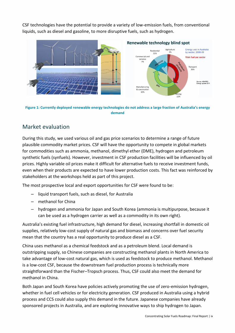
Tremendous advances have been made in the development and deployment of renewable energy
technologies. However, it is not always recognised that while most popular attention is given to
renewable technologies that produce electricity, around 80% of global and Australian primary
energy demand is currently supplied by petroleum and gas, which are largely used for transport
and heat (Figure 1).
The currently deployed renewable technologies are thus only addressing part of the problem of
carbon dioxide (CO2) emissions. Tackling the emission reductions needed for a 2°C climate change
scenario will require either a significant change in energy consumption (e.g. electrified transport),
or identifying sources of combustible fuels with lower carbon intensity than petroleum and gas.
Carbon capture and storage (CCS) is also likely to play a role. It is therefore widely recognised that
a portfolio approach with multiple technologies is likely to be needed.
Concentrating Solar Fuels Roadmap: Final Report | ix
CSF technologies have the potential to provide a variety of low-emission fuels, from conventional
liquids, such as diesel and gasoline, to more disruptive fuels, such as hydrogen.
Figure 1: Currently deployed renewable energy technologies do not address a large fraction of Australia’s energy
demand
Market evaluation
During this study, we used various oil and gas price scenarios to determine a range of future
plausible commodity market prices. CSF will have the opportunity to compete in global markets
for commodities such as ammonia, methanol, dimethyl ether (DME), hydrogen and petroleum
synthetic fuels (synfuels). However, investment in CSF production facilities will be influenced by oil
prices. Highly variable oil prices make it difficult for alternative fuels to receive investment funds,
even when their products are expected to have lower production costs. This fact was reinforced by
stakeholders at the workshops held as part of this project.
The most prospective local and export opportunities for CSF were found to be:
– liquid transport fuels, such as diesel, for Australia
– methanol for China
– hydrogen and ammonia for Japan and South Korea (ammonia is multipurpose, because it
can be used as a hydrogen carrier as well as a commodity in its own right).
Australia’s existing fuel infrastructure, high demand for diesel, increasing shortfall in domestic oil
supplies, relatively low-cost supply of natural gas and biomass and concerns over fuel security
mean that the country has a real opportunity to produce diesel as a CSF.
China uses methanol as a chemical feedstock and as a petroleum blend. Local demand is
outstripping supply, so Chinese companies are constructing methanol plants in North America to
take advantage of low-cost natural gas, which is used as feedstock to produce methanol. Methanol
is a low-cost CSF, because the downstream fuel production process is technically more
straightforward than the Fischer–Tropsch process. Thus, CSF could also meet the demand for
methanol in China.
Both Japan and South Korea have policies actively promoting the use of zero-emission hydrogen,
whether in fuel cell vehicles or for electricity generation. CSF produced in Australia using a hybrid
process and CCS could also supply this demand in the future. Japanese companies have already
sponsored projects in Australia, and are exploring innovative ways to ship hydrogen to Japan.
x | Concentrating Solar Fuels Roadmap: Final Report
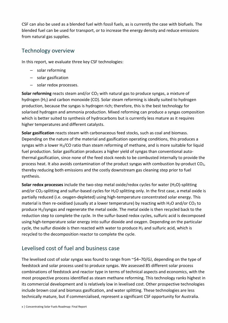
CSF can also be used as a blended fuel with fossil fuels, as is currently the case with biofuels. The
blended fuel can be used for transport, or to increase the energy density and reduce emissions
from natural gas supplies.
Technology overview
In this report, we evaluate three key CSF technologies:
– solar reforming
– solar gasification
– solar redox processes.
Solar reforming reacts steam and/or CO2 with natural gas to produce syngas, a mixture of
hydrogen (H2) and carbon monoxide (CO). Solar steam reforming is ideally suited to hydrogen
production, because the syngas is hydrogen rich; therefore, this is the best technology for
solarised hydrogen and ammonia production. Mixed reforming can produce a syngas composition
which is better suited to synthesis of hydrocarbons but is currently less mature as it requires
higher temperatures and different catalysts.
Solar gasification reacts steam with carbonaceous feed stocks, such as coal and biomass.
Depending on the nature of the material and gasification operating conditions, this produces a
syngas with a lower H2/CO ratio than steam reforming of methane, and is more suitable for liquid
fuel production. Solar gasification produces a higher yield of syngas than conventional auto-
thermal gasification, since none of the feed stock needs to be combusted internally to provide the
process heat. It also avoids contamination of the product syngas with combustion by-product CO2,
thereby reducing both emissions and the costly downstream gas cleaning step prior to fuel
synthesis.
Solar redox processes include the two-step metal oxide/redox cycles for water (H2O)-splitting
and/or CO2-splitting and sulfur-based cycles for H2O splitting only. In the first case, a metal oxide is
partially reduced (i.e. oxygen-depleted) using high-temperature concentrated solar energy. This
material is then re-oxidised (usually at a lower temperature) by reacting with H2O and/or CO2 to
produce H2/syngas and regenerate the metal oxide. The metal oxide is then recycled back to the
reduction step to complete the cycle. In the sulfur-based redox cycles, sulfuric acid is decomposed
using high-temperature solar energy into sulfur dioxide and oxygen. Depending on the particular
cycle, the sulfur dioxide is then reacted with water to produce H2 and sulfuric acid, which is
recycled to the decomposition reactor to complete the cycle.
Levelised cost of fuel and business case
The levelised cost of solar syngas was found to range from ~$4–70/GJ, depending on the type of
feedstock and solar process used to produce syngas. We assessed 85 different solar process
combinations of feedstock and reactor type in terms of technical aspects and economics, with the
most prospective process identified as steam methane reforming. This technology ranks highest in
its commercial development and is relatively low in levelised cost. Other prospective technologies
include brown coal and biomass gasification, and water splitting. These technologies are less
technically mature, but if commercialised, represent a significant CSF opportunity for Australia.
Concentrating Solar Fuels Roadmap: Final Report | xi
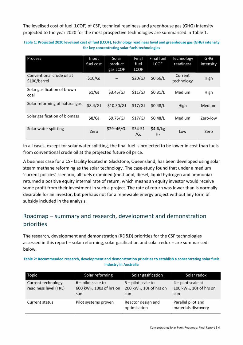
The levelised cost of fuel (LCOF) of CSF, technical readiness and greenhouse gas (GHG) intensity
projected to the year 2020 for the most prospective technologies are summarised in Table 1.
Table 1: Projected 2020 levelised cost of fuel (LCOF), technology readiness level and greenhouse gas (GHG) intensity
for key concentrating solar fuels technologies
Process Input fuel cost
Solar product gas LCOF
Final fuel
LCOF
Final fuel LCOF
Technology readiness
GHG intensity
Conventional crude oil at $100/barrel
$16/GJ – $20/GJ $0.56/L Current
technology High
Solar gasification of brown coal
$1/GJ $3.45/GJ $11/GJ $0.31/L Medium High
Solar reforming of natural gas $8.4/GJ $10.30/GJ $17/GJ $0.48/L High Medium
Solar gasification of biomass $8/GJ $9.75/GJ $17/GJ $0.48/L Medium Zero-low
Solar water splitting Zero
$29–46/GJ $34-51 /GJ
$4-6/kg H2
Low Zero
In all cases, except for solar water splitting, the final fuel is projected to be lower in cost than fuels
from conventional crude oil at the projected future oil price.
A business case for a CSF facility located in Gladstone, Queensland, has been developed using solar
steam methane reforming as the solar technology. The case-study found that under a medium
‘current policies’ scenario, all fuels examined (methanol, diesel, liquid hydrogen and ammonia)
returned a positive equity internal rate of return, which means an equity investor would receive
some profit from their investment in such a project. The rate of return was lower than is normally
desirable for an investor, but perhaps not for a renewable energy project without any form of
subsidy included in the analysis.
Roadmap – summary and research, development and demonstration priorities
The research, development and demonstration (RD&D) priorities for the CSF technologies
assessed in this report – solar reforming, solar gasification and solar redox – are summarised
below.
Table 2: Recommended research, development and demonstration priorities to establish a concentrating solar fuels
industry in Australia
Topic Solar reforming Solar gasification Solar redox
Current technology readiness level (TRL)
6 – pilot scale to 600 kWth, 100s of hrs on sun
5 – pilot scale to 200 kWth, 10s of hrs on sun
4 – pilot scale at 100 kWth, 10s of hrs on sun
Current status Pilot systems proven Reactor design and optimisation
Parallel pilot and materials discovery

xii | Concentrating Solar Fuels Roadmap: Final Report
Topic Solar reforming Solar gasification Solar redox
Ready for demo/scale-up
German Aerospace Research Centre (DLR) constructing 750 kWth demo at the Plataforma Solar de Almeria (Spain)
Barriers Non-technical: need long-term operational experience for bankability
Materials handling (e.g. window, bed material, molten salt, feed stock)
Char conversion
Tar formation
Long-term stability of reactor and operational experience
Long-term stability of reactor materials
Low thermal efficiency
R&D priorities (2 years) Lifetime of alloys Solar integration to the gasification reactor
Materials handling
Fundamental material investigations
Mixed reforming catalyst development
Pilot-scale on-sun performance assessment
Overall system concepts
R&D priorities (5 years) Support demonstration-scale (>=5 MWth) requirements
Laboratory verification of material performance
Innovative microchannel reactor/receivers
On-sun performance assessment
R&D priorities (10 years) Integrated sun to fuel systems
Scale-up to demonstration-scale systems integrated with downstream syngas cleaning and upgrade systems
Scale-up to pilot-scale systems
Pilot system priorities Proof of concept complete
Long-term demonstration facility
Materials handling
Recuperation systems
Pilot system Now 5 years 5–10 years
Demonstration 4–5 years 10 years 10 years
Pre-commercial 5–10 years 10–15 years 10+ years
Ancillary system development (cross-cutting)
Cost-effective syngas storage
Small-scale fuel synthesis (fuel/methanol/ammonia)
Fuel flexible synthesis processes
Hydrogen transport systems (liquid hydrogen, ammonia, methylcyclohexane)
Concentrating Solar Fuels Roadmap: Final Report | xiii
Recommended actions to establish and support an Australian concentrating solar fuels industry
Our assessments indicate that the most prospective domestic market in the near-to-medium term
future is for liquid transport fuels (gasoline, diesel, aviation turbine fuel, and perhaps in the longer
term, methanol). Market forecasts out to the year 2050 indicate Australian liquid transport fuel
usage will continue to be dominated by diesel and gasoline, with electricity providing less than 5%
of the demand and hydrogen not being used at all.
With diminishing domestic supplies of petroleum, liquid fuels from natural gas, coal and oil shale
are expected to play an increasing role. If cost-effective, there will be opportunities to hybridise
these alternatives with solar thermal energy to both reduce emissions and provide a transitional
pathway from fossil fuels to truly renewable sources of transport fuels produced via syngas.
Blending of methanol may also provide an intermediate path as it is expected that methanol
synthesis is likely to be cheaper and more mature for implementation at a scale appropriate for
solar syngas production than Fischer–Tropsch or methanol-to-gasoline processes.
In terms of the international market, opportunities for Australian CSF could come from countries
such as China, South Korea and Japan. Japan, in particular, could ultimately become a major
importer of CSF, with a growing interest in hydrogen for its increasing fuel cell market. Other fuels,
such as methanol, DME and even ammonia are also of interest to Japan as it seeks to ensure its
future energy security while reducing its emissions. All of these fuels could be produced, fully or
partly, from Australian solar energy using the technologies discussed in this roadmap. In view of
Japan’s interest in hydrogen, this fuel has also been included in the roadmap, along with the more
conventional liquid fuels that can be produced from syngas.
We have examined the challenges and solutions to implementation of a CSF industry, considering
technology development, societal acceptance, market development and customer demand. From
this, we have developed a detailed list of R&D priorities. Successful establishment of a CSF
industry in Australia would be aided by suitable actions across stakeholder groups, including
research organisations, state and federal governments, funding agencies and existing industrial
players. A detailed listing of suggested actions for each group has been assembled, which can be
broadly summarised as:
– CSF R&D should be a priority, and should target
parallel development of multiple technology options to enable a staged approach
to reducing carbon intensity
materials discovery for redox metal oxide systems
reactor design and development for gasification based processes
reactor lifetimes
recuperation of heat from reactants to maximise efficiency
full CSF production evaluation to final products
low-cost underground storage of hydrogen/syngas mixtures
high temperature storage and heat transfer fluids.
– ARENA could adopt renewable fuels as a new priority area.

xiv | Concentrating Solar Fuels Roadmap: Final Report
– State mandates for biofuels could be generalised to include all renewable fuels.
– The Renewable Energy Target could be expanded or replicated to include renewable fuels.
– Fossil fuel subsidies (e.g. diesel excise rebates) should be removed and/or appropriate
carbon-pricing measures should be considered.
– A pipeline of Australian concentrating solar power (CSP) deployment is needed to build
capability and a supply chain for a future CSF industry.
– A regional test platform should be established at 5–10 MWth scale for a range of
concentrating solar thermal technologies, including a demonstration of solar steam
methane reforming.
– Bilateral government negotiations with Japan and others could establish the foundation
for an international trade in renewable fuels.
This study’s analysis suggests that CSF approaches to pure solar hydrogen production are likely to
be less than half the cost of PV plus electrolysis. The competitiveness of CSF with advanced
biofuels options will depend on the cost of available biomass; but as there is only a limited supply
potential for cheap biomass, both approaches have a role. The competiveness of CSF with fossil
fuels plus CCS is hard to determine at this stage. Overall, we suggest that major policy initiatives
should be made in a technology-neutral manner, such that all approaches can compete in new,
zero-emission fuel markets.
With suitable strategic initiatives in these directions, an Australian CSF industry established over
the next two decades could become of equal or larger value to our economy than that of the fossil
fuel industry today.

2 | Concentrating Solar Fuels Roadmap: Final Report
1 Introduction
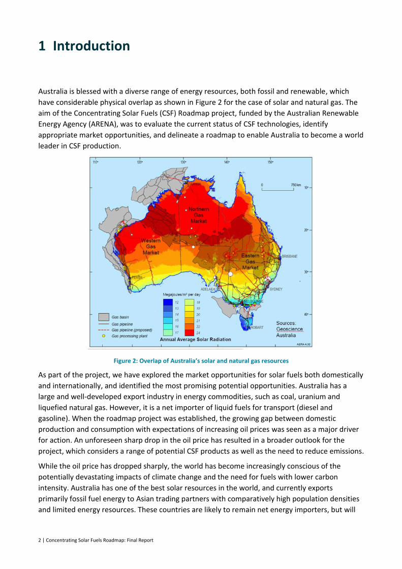
Australia is blessed with a diverse range of energy resources, both fossil and renewable, which
have considerable physical overlap as shown in Figure 2 for the case of solar and natural gas. The
aim of the Concentrating Solar Fuels (CSF) Roadmap project, funded by the Australian Renewable
Energy Agency (ARENA), was to evaluate the current status of CSF technologies, identify
appropriate market opportunities, and delineate a roadmap to enable Australia to become a world
leader in CSF production.
Figure 2: Overlap of Australia’s solar and natural gas resources
As part of the project, we have explored the market opportunities for solar fuels both domestically
and internationally, and identified the most promising potential opportunities. Australia has a
large and well-developed export industry in energy commodities, such as coal, uranium and
liquefied natural gas. However, it is a net importer of liquid fuels for transport (diesel and
gasoline). When the roadmap project was established, the growing gap between domestic
production and consumption with expectations of increasing oil prices was seen as a major driver
for action. An unforeseen sharp drop in the oil price has resulted in a broader outlook for the
project, which considers a range of potential CSF products as well as the need to reduce emissions.
While the oil price has dropped sharply, the world has become increasingly conscious of the
potentially devastating impacts of climate change and the need for fuels with lower carbon
intensity. Australia has one of the best solar resources in the world, and currently exports
primarily fossil fuel energy to Asian trading partners with comparatively high population densities
and limited energy resources. These countries are likely to remain net energy importers, but will
Concentrating Solar Fuels Roadmap: Final Report | 3
seek more sustainable sources of energy. CSF technologies have the potential to make use of
Australia’s unique resources for new export opportunities.
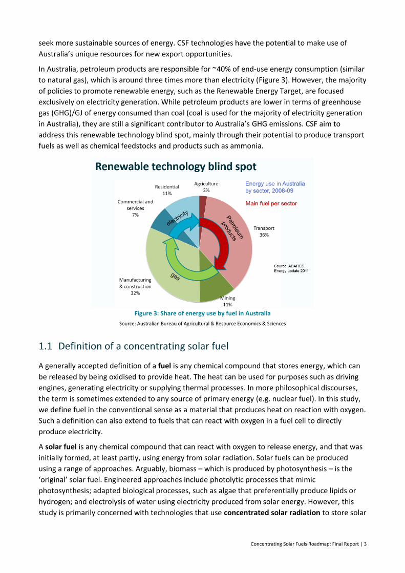
In Australia, petroleum products are responsible for ~40% of end-use energy consumption (similar
to natural gas), which is around three times more than electricity (Figure 3). However, the majority
of policies to promote renewable energy, such as the Renewable Energy Target, are focused
exclusively on electricity generation. While petroleum products are lower in terms of greenhouse
gas (GHG)/GJ of energy consumed than coal (coal is used for the majority of electricity generation
in Australia), they are still a significant contributor to Australia’s GHG emissions. CSF aim to
address this renewable technology blind spot, mainly through their potential to produce transport
fuels as well as chemical feedstocks and products such as ammonia.
Figure 3: Share of energy use by fuel in Australia
Source: Australian Bureau of Agricultural & Resource Economics & Sciences
1.1 Definition of a concentrating solar fuel
A generally accepted definition of a fuel is any chemical compound that stores energy, which can
be released by being oxidised to provide heat. The heat can be used for purposes such as driving
engines, generating electricity or supplying thermal processes. In more philosophical discourses,
the term is sometimes extended to any source of primary energy (e.g. nuclear fuel). In this study,
we define fuel in the conventional sense as a material that produces heat on reaction with oxygen.
Such a definition can also extend to fuels that can react with oxygen in a fuel cell to directly
produce electricity.
A solar fuel is any chemical compound that can react with oxygen to release energy, and that was
initially formed, at least partly, using energy from solar radiation. Solar fuels can be produced
using a range of approaches. Arguably, biomass – which is produced by photosynthesis – is the
‘original’ solar fuel. Engineered approaches include photolytic processes that mimic
photosynthesis; adapted biological processes, such as algae that preferentially produce lipids or
hydrogen; and electrolysis of water using electricity produced from solar energy. However, this
study is primarily concerned with technologies that use concentrated solar radiation to store solar

4 | Concentrating Solar Fuels Roadmap: Final Report
energy in a chemical form as a CSF, via high-temperature thermochemical reactions. This can be
accomplished in both hybrid solar-fossil fuel systems and truly renewable solar-based systems.
In hybrid systems, solar energy is combined with a carbonaceous fuel, such as natural gas, biomass
or coal, to form a product that embodies both renewable and fossil energy. Concentrated, high-
temperature solar energy provides the heat required to drive endothermic (heat-absorbing)
chemical reactions, which convert the carbonaceous fuel into intermediate compounds (typically
syngas, a mixture of carbon monoxide and hydrogen). In doing so, the amount of solar energy
embodied in the final product is equal to the enthalpy change of the heat absorbing chemical
reactions. Syngas is the feed stock for further processing into a range of synthetic liquid fuels and
chemicals, such as conventional liquid hydrocarbons and alcohols.
In a fully renewable system, concentrated solar energy is used to dissociate water and carbon
dioxide to produce hydrogen and/or syngas. These materials can be oxidised by combustion to
drive a heat cycle or, in the case of hydrogen, a fuel cell to drive an electric motor; or in the case of
syngas used to produce a range of possible end products. However, we have excluded solar-
generated electricity from our study, because electron currents are energy carriers (or vectors),
rather than a means of energy storage.
CSF are a potential energy source for the same applications as fossil fuels, such as:
– onboard combustion for transportation
– electrical power generation
– on-demand production of process heat.
Of these, transportation may be the most attractive near-term application in Australia for a solar
fuel, due to both the high demand and inherently high value of liquid transportation fuels.
In a future energy mix that is increasingly supplied by otherwise variable renewable energy
sources such as solar and wind, solar fuels offer high-density energy storage:
– over timescales up to many months
– for cost-effective transport over long distances (including internationally), from point of
capture to point of use.
1.2 Current and future fluid-phase fuels
Fluid fuels will retain an important role for the foreseeable future. However, the choice of the
dominant fluid fuel may well change over time. Possibilities include hydrogen, methane,
methanol, dimethyl ether (DME), ammonia and synthesised ‘drop-in fuels’.
– Hydrogen (H2) can be produced from fossil fuels or splitting of water. It has been the
subject of much promotion and anticipation over many decades, due to its advantage of
combustion to pure water. Its major disadvantage is that it is extremely difficult to achieve
a practical volumetric or mass-based energy density for storage or long-distance
transport.
– Methane (CH4) is the main constituent of natural and coal seam gas. Liquefaction is costly
but practical, and is now proven for international trade. Methane can be synthesised from
other sources, such as coal or biomass, but it is also a key feedstock for chemical synthesis
Concentrating Solar Fuels Roadmap: Final Report | 5
via reforming. Methane is primarily considered as a feedstock for syngas production in this
report, rather than as a CSF product option.
– Methanol (CH3OH) is the simplest alcohol. It can be synthesised from base sources, such
as natural gas, coal or biomass, and it is more convenient for use and transport than
methane. However, it is carcinogenic and has a lower energy density than current oil-
based fuels.
– DME (CH3OCH3) is synthesised from methanol. It requires a slightly elevated pressure to
be maintained as a liquid, similar to liquefied petroleum gas (LPG). It is not carcinogenic
and can be transported relatively easily.
– Ammonia (NH3) is a commercially established commodity product used in the fertiliser,
explosive and chemical industries, and its practicality as a liquid fuel has been extensively
studied. It must be kept at slightly elevated pressure to be maintained as a liquid at
ambient temperature. A large spill is a caustic and cryogenic hazard. It can be seen as a
practical liquid vector for use of hydrogen, since it is made from hydrogen combined with
nitrogen from the air, and can be dissociated back to nitrogen and hydrogen, albeit with a
significant energy input due to the endothermic dissociation reaction.
– Synthesised drop-in fuels that meet existing standards for diesel, gasoline and aviation
fuels have the advantage of use within the existing infrastructure and marketplace. Drop-
in fuels can be synthesised from coal, natural gas or biomass – or any other source of
hydrogen and carbon – via production of syngas.
Of these various options, they fall into one of two opposing groups: those that contain carbon and
those that do not. If the carbon in a fuel originates from biomass, then nature provides a closed
cycle. However, if the carbon originates from a fossil fuel, then its combustion will release carbon
dioxide (CO2) with greater or lesser intensity depending on the processes of producing and using
the fuel. If the CO2 is captured at the point of combustion, it could be sequestered, or, in principle,
be returned for recycling.
1.3 Hydrogen from photovoltaics and electrolysis as an alternative solar fuel
As part of this road map project, we have assessed the production of hydrogen from photovoltaics
(PV) and electrolysis in a companion report. Recent advances and cost reduction in both PV and
proton exchange membrane electrolysis has led to growing interest in this potential pathway for
the production of renewable fuels. Hydrogen produced from PV-driven electrolysis is thus a
baseline to which CSF alternatives can be compared. The following is extracted from the executive
summary of the companion report (Hinkley et al., 2015a), with the hydrogen costs converted to
$/GJ for consistency with the CSF roadmap in Table 3.
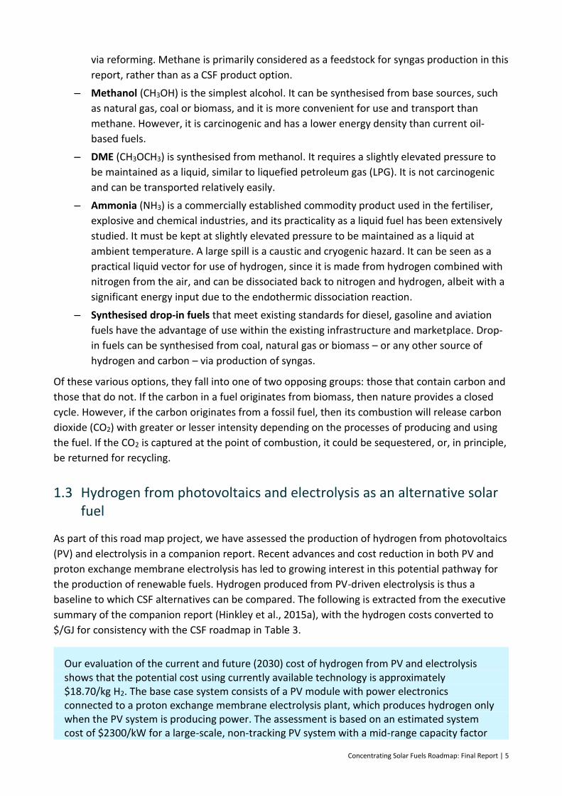
Our evaluation of the current and future (2030) cost of hydrogen from PV and electrolysis shows that the potential cost using currently available technology is approximately $18.70/kg H2. The base case system consists of a PV module with power electronics connected to a proton exchange membrane electrolysis plant, which produces hydrogen only when the PV system is producing power. The assessment is based on an estimated system cost of $2300/kW for a large-scale, non-tracking PV system with a mid-range capacity factor
6 | Concentrating Solar Fuels Roadmap: Final Report
of 20.5% and a weighted average cost of capital of 6.4%, as recently published by the CO2CRC (2015). It is assumed that the uninstalled cost of the electrolyser and associated components is $2285/kW, in line with recent estimates from the European Fuel Cell and Hydrogen Joint Undertaking (Bertuccioli et al., 2014). Significant cost reductions are predicted for both these technologies, cutting the estimated cost of hydrogen to $9.10/kg by 2030.
The study also examined the potential of battery storage to reduce the cost of hydrogen production. In this scenario, the battery system was used to condition the power supply from the PV system, with sufficient storage capacity provided to enable continuous operation of the electrolyser. Lithium-ion battery technology was selected as the most appropriate. In both current and future scenarios, battery storage increased the cost of hydrogen relative to the base case, due to its relatively high cost compared with energy production from PV. Based on current and future battery costs of $540 and $200/kWh, the estimated cost of hydrogen was $28.40 and $11.30/kg in 2015 and 2030, respectively. While the current cost with battery storage is much higher than the case without storage, the gap is expected to close if projected battery cost targets are met. It was also interesting to note that the addition of any amount of Li-ion battery storage to the system increased the hydrogen production cost relative to the base case.
The estimates of hydrogen production costs are significantly higher than the current cost of its production from steam methane reforming, which are around $1.50–2.50/kg H2. Naturally, however, fossil fuels such as methane produce significant greenhouse gas (GHG) emissions, while PV–electrolysis systems are instead based on renewable solar resources and produce zero-emission fuel.
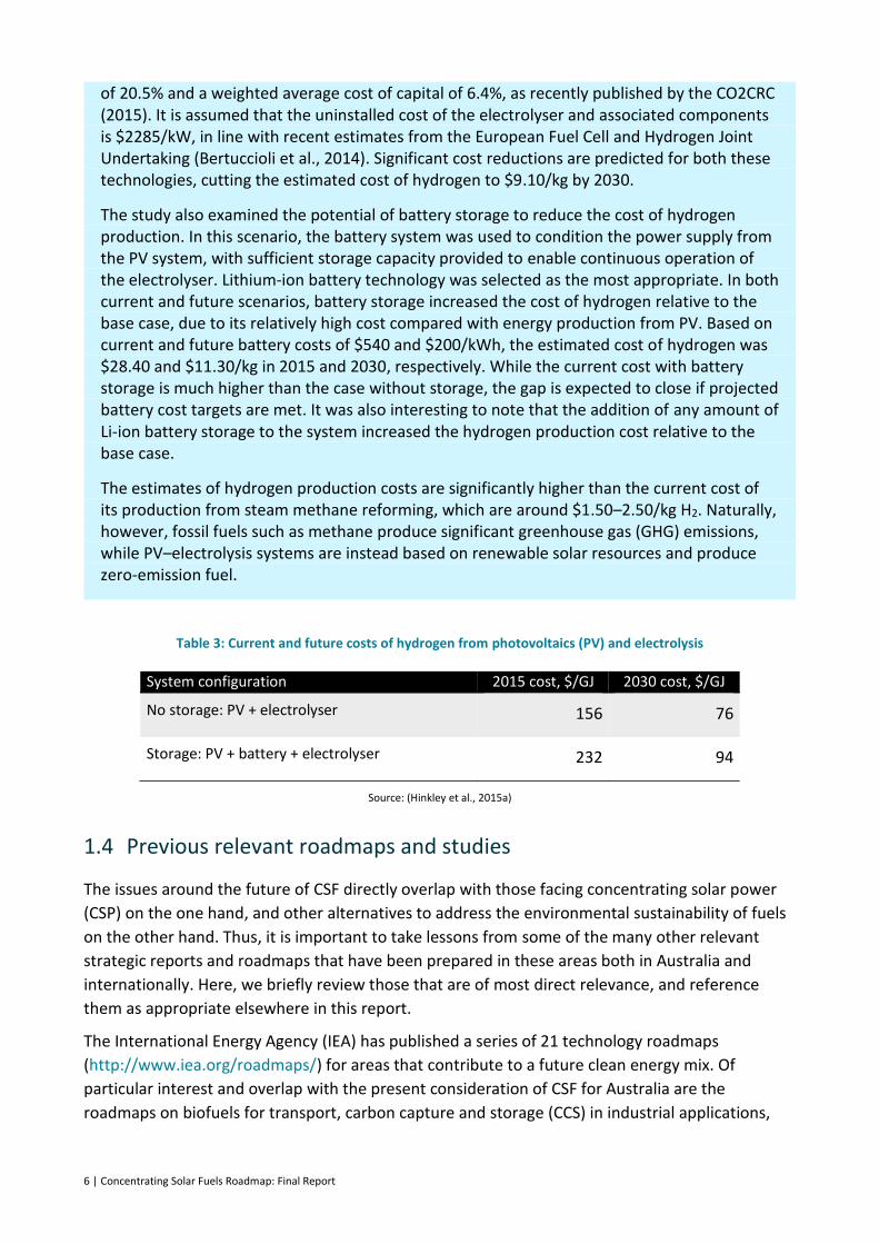
Table 3: Current and future costs of hydrogen from photovoltaics (PV) and electrolysis
System configuration 2015 cost, $/GJ 2030 cost, $/GJ
No storage: PV + electrolyser 156 76
Storage: PV + battery + electrolyser 232 94
Source: (Hinkley et al., 2015a)
1.4 Previous relevant roadmaps and studies
The issues around the future of CSF directly overlap with those facing concentrating solar power
(CSP) on the one hand, and other alternatives to address the environmental sustainability of fuels
on the other hand. Thus, it is important to take lessons from some of the many other relevant
strategic reports and roadmaps that have been prepared in these areas both in Australia and
internationally. Here, we briefly review those that are of most direct relevance, and reference
them as appropriate elsewhere in this report.
The International Energy Agency (IEA) has published a series of 21 technology roadmaps
(http://www.iea.org/roadmaps/) for areas that contribute to a future clean energy mix. Of
particular interest and overlap with the present consideration of CSF for Australia are the
roadmaps on biofuels for transport, carbon capture and storage (CCS) in industrial applications,
Concentrating Solar Fuels Roadmap: Final Report | 7
the chemical industry, hydrogen and fuel cells, and solar thermal electricity. The various IEA
roadmaps are briefly summarised below, together with several other relevant studies.
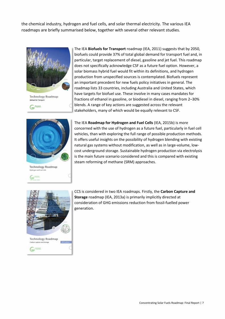
The IEA Biofuels for Transport roadmap (IEA, 2011) suggests that by 2050,
biofuels could provide 37% of total global demand for transport fuel and, in
particular, target replacement of diesel, gasoline and jet fuel. This roadmap
does not specifically acknowledge CSF as a future fuel option. However, a
solar biomass hybrid fuel would fit within its definitions, and hydrogen
production from unspecified sources is contemplated. Biofuels represent
an important precedent for new fuels policy initiatives in general. The
roadmap lists 33 countries, including Australia and United States, which
have targets for biofuel use. These involve in many cases mandates for
fractions of ethanol in gasoline, or biodiesel in diesel, ranging from 2–30%
blends. A range of key actions are suggested across the relevant
stakeholders, many of which would be equally relevant to CSF.
The IEA Roadmap for Hydrogen and Fuel Cells (IEA, 2015b) is more
concerned with the use of hydrogen as a future fuel, particularly in fuel cell
vehicles, than with exploring the full range of possible production methods.
It offers useful insights on the possibility of hydrogen blending with existing
natural gas systems without modification, as well as in large-volume, low-
cost underground storage. Sustainable hydrogen production via electrolysis
is the main future scenario considered and this is compared with existing
steam reforming of methane (SRM) approaches.
CCS is considered in two IEA roadmaps. Firstly, the Carbon Capture and
Storage roadmap (IEA, 2013a) is primarily implicitly directed at
consideration of GHG emissions reduction from fossil-fuelled power
generation.
8 | Concentrating Solar Fuels Roadmap: Final Report
Secondly, the Carbon Capture and Storage in Industrial Applications
(IEA/UNIDO, 2011) roadmap considers the application of CCS to the major
chemical production processes, such as conventional ammonia and
methanol production, plus also other high-emitting industries, such as iron,
steel and cement.
The Energy and GHG Reductions in the Chemical Industry via Catalytic
Processes roadmap (IEA, 2013b)) has useful inputs for the present CSF
roadmap via the possibility that hybrid solar fuels options might be
combined with CCS for an overall least-cost solution. The estimated costs
show that sequestration of a high-purity stream of CO2 resulting from, for
example, SRM (which could be solar driven) costs around half that of
overall CCS applied to iron and steel, where complex capture technologies
must be added in. The Industrial Applications roadmap also flags the
prospect of capturing pure CO2 streams from biomass gasification (which
could be solar driven) for sequestration for an overall negative emissions
process. The Chemical Processes roadmap raises the possibility of
ammonia or methanol production from renewably sourced hydrogen.
Of most direct relevance to CSF is the Innovative Hydrogen Processes
Project (Ewan et al., 2007). This was a European-based collaborative
international investigation that aimed to define an R&D roadmap in high-
temperature technologies for massive hydrogen production. Its scope
included processes driven by nuclear heat; but of most relevance, it
directly considered high-temperature solar thermochemical processes. An
underlying assumption of the study is that a hydrogen economy is
inevitable, but is unlikely to be implemented before 2050. Traditional use
of hydrogen is reported as 50% for ammonia production and 37% for
refinery processes in 2002. It is projected that large and increasing
amounts of hydrogen will be used in the refining of heavy hydrocarbons
and increasingly for advanced biomass conversion to liquids. The report
suggests that this will be the first target market for fully renewable
hydrogen, with use for transport and as storage for renewable energy
emerging progressively from 2020 onwards. A cost analysis of hydrogen
production options suggests that combining solar with SRM would only
increase costs by around 10%. Pure solar thermochemical production, on
the other hand, is suggested to be three times more costly than that of
SRM. PV-driven electrolysis solutions would be more than twice the cost of
solar thermochemical routes as estimated in 2006. Specific technology
choices and timing are suggested, and arguably the progress in R&D since
2006 has followed this to a reasonable degree.
Concentrating Solar Fuels Roadmap: Final Report | 9
CSF is built around the same basic concentrating solar thermal fields as
used in CSP systems. As such, the progress of this existing, well-established
industry will largely set the scene for the development of a CSF industry.
The IEA roadmap on Solar Thermal Electricity (IEA, 2014b) is built on an
earlier (2010) version. It reports strong growth in the concentrated solar
sector, if slower than foreshadowed. Barriers encountered include
insufficiently accurate direct normal irradiance (DNI) data, policy
uncertainty, difficulties with planning and environmental approvals, and
expensive financing. Overall, strong deployment growth is expected to
continue, and this is foreshadowed to be accompanied by a halving of
capital cost by 2050. Most of that cost reduction is in the solar field and
balance-of-system aspects that would be common to CSF systems. Solar
fuels applications are reviewed as an extended future application of
concentrating solar thermal systems. A relevant list of suggested actions
for governments is offered.
The Japanese Government has recently, after the Fukushima disaster,
developed a new strategic energy plan including a Strategic Roadmap for
Hydrogen and Fuel Cells (METI, 2014). This roadmap ‘compiles views on
how Japan would be able to make use of hydrogen, goals to be achieved in
each step of manufacturing, transportation and storage of hydrogen, and
collaborative efforts among industry, academia and government for
achieving these goals, into a road map with clear time frames attached,
taking into account the significance of an initiative for disseminating
hydrogen energy.’
Some relevant studies specific to Australia are also useful to the present CSF roadmap
investigation: these are summarised below.
Realising the Potential for CSP in Australia (IT Power (Australia) Pty
Limited, 2012) is a detailed study carried out for the Australian Solar
Institute (a precursor organisation to ARENA). As well as analysing
technologies, costs and market value of CSP, this study reviewed the
challenges and suggested actions that Australia could take to build a CSP
industry. It proposed an optimistic/realistic growth scenario, which was
built on the assumed starting point of completion of the Solar Flagships
project that was approved by government at that time, leading up to a
major push into CSF in around 2050.
10 | Concentrating Solar Fuels Roadmap: Final Report
The Australian Hydrogen Technology Roadmap (Wyld Group, 2008) was
produced in 2008. As with the IEA hydrogen roadmap, fuel cells and their
uptake were a major part of the consideration, although the report clearly
notes many separate aspects of hydrogen. A vision is offered that: ‘By 2020
Australia is effectively exploiting emerging hydrogen and fuel cell market
and supply-chain opportunities, locally and globally.’ The study compares
the cost of production via SRM, coal gasification and electrolysis, with
renewable electrolysis routes judged to be three times more than SRM. A
detailed analysis of barriers and suggested strategies is offered, many of
which are relevant to CSF.
CSIRO’s Flight Path to Sustainable Aviation Fuels (CSIRO, 2011b) made the
case for an Australian and New Zealand bio-derived jet fuel industry. The
report states that over the next 20 years, this could result in 12,000 new
jobs, reduce Australia’s reliance on fuel imports by $2 billion per year, and
decrease GHG emissions from aviation by 17%. Key challenges for the
sector that apply to CSF include uncertainty in investment for the refining
sector. Access arrangements for new fuel suppliers would also need to be
established.
Fuel for thought (CSIRO, 2008) was the final product of the Future Fuel
Forum, an exercise run by CSIRO that brought together stakeholders across
the transport industry. The forum and report identified key risks,
opportunities and challenges facing the sector into the future. Those most
relevant for CSF include the following:
The future fuel mix will have to be more diverse.
The transport sector will only make modest contributions to
reducing GHG emissions.
Simultaneous, rather than sequential, response is required to
address the challenges.
Australia is vulnerable to changing market conditions.
Government will have a large role in fostering any fuel transition.
Technology alone will not be sufficient to reduce GHG emissions
and meet the supply gap.
Solar fuels were not considered at the forum. However, mapping CSF to
the findings shows that CSF would have a role to play in meeting the
challenges and opportunities identified in the study.

Concentrating Solar Fuels Roadmap: Final Report | 11
The Australian Liquid Fuels Technology Assessment estimates the current
and possible future costs of established and emerging liquid fuel
production technologies under Australian conditions. While a wide range
of technologies are reviewed, the emphasis is on more traditional
approaches, and CSF technologies are not covered in any detail. A single
CSF example (a proprietary unproven water plus CO2 splitting system from
Israel) is considered and analysed to have a suggested high cost of final
fuel. The study also assumed high costs of capital for emerging
technologies in particular, which provided additional barriers in terms of
their perceived cost. The assumed weighted average cost of capital was
12.2% for emerging technologies.
The Advanced Biofuels Study – Strategic Directions for Australia report
(LEK, 2011) closely mirrors the concerns and aspirations of the CSF sector.
Advanced biofuels overlap in technology and end product – and hence,
market – with CSF technologies. The report recognises a: ‘mounting
urgency around the world to find affordable and sustainable alternatives to
non-renewable transport fuels’.
A United States mandate of 136 GL by 2022 and a European mandate for
10% of renewable transport fuel use by 2020 are noted. These mandates
go beyond just traditional ethanol to embrace advanced fuels as well.
Domestically, the industry sectors with high fuel demand and few
alternatives to non-renewable fuels are suggested to be most prospective
for advanced biofuels, and hence by extension, CSF also. These industries
are aviation, defence, freight road transport, mining and marine.
The report postulates a range of possible aspirations for the industry that
include, at the most optimistic end, the possibility of exports. It implies that
it will be more favourable to first meet the vast majority of domestic fuel
demand, and then contemplate exports. A key recommendation,
supported by short, medium and long-term detailed actions, is that the
federal government should lay the foundations to enable the industry to
reach an aspiration of at least 15–30 GL/year.
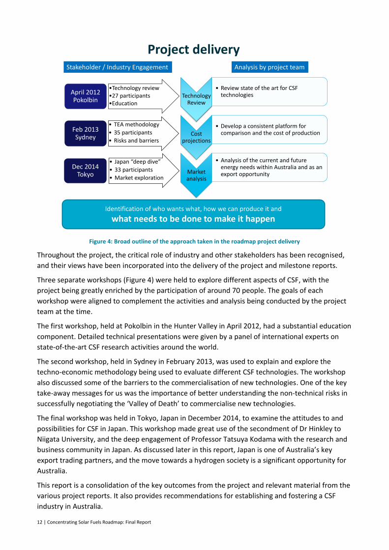
1.5 Study methodology
An overview of the development of this project is provided in Figure 4. The project was sequential
in some respects, in that the following separate activities were reported individually to ARENA in a
series of milestone reports:
– a review of the state of the art of solar technologies for fuel production
– screening and techno-economic evaluation of promising technologies in partnership with
industry
– an assessment of potential markets and product options.
12 | Concentrating Solar Fuels Roadmap: Final Report
Figure 4: Broad outline of the approach taken in the roadmap project delivery
Throughout the project, the critical role of industry and other stakeholders has been recognised,
and their views have been incorporated into the delivery of the project and milestone reports.
Three separate workshops (Figure 4) were held to explore different aspects of CSF, with the
project being greatly enriched by the participation of around 70 people. The goals of each
workshop were aligned to complement the activities and analysis being conducted by the project
team at the time.
The first workshop, held at Pokolbin in the Hunter Valley in April 2012, had a substantial education
component. Detailed technical presentations were given by a panel of international experts on
state-of-the-art CSF research activities around the world.
The second workshop, held in Sydney in February 2013, was used to explain and explore the
techno-economic methodology being used to evaluate different CSF technologies. The workshop
also discussed some of the barriers to the commercialisation of new technologies. One of the key
take-away messages for us was the importance of better understanding the non-technical risks in
successfully negotiating the ‘Valley of Death’ to commercialise new technologies.
The final workshop was held in Tokyo, Japan in December 2014, to examine the attitudes to and
possibilities for CSF in Japan. This workshop made great use of the secondment of Dr Hinkley to
Niigata University, and the deep engagement of Professor Tatsuya Kodama with the research and
business community in Japan. As discussed later in this report, Japan is one of Australia’s key
export trading partners, and the move towards a hydrogen society is a significant opportunity for
Australia.
This report is a consolidation of the key outcomes from the project and relevant material from the
various project reports. It also provides recommendations for establishing and fostering a CSF
industry in Australia.
Project delivery
Identification of who wants what, how we can produce it and
what needs to be done to make it happen
Analysis by project team
Technology Review
• Review state of the art for CSF technologies
Cost projections
• Develop a consistent platform for comparison and the cost of production
Market analysis
• Analysis of the current and future energy needs within Australia and as an export opportunity
•Technology review•27 participants•Education
April 2012 Pokolbin
• TEA methodology
• 35 participants
• Risks and barriers
Feb 2013 Sydney
• Japan “deep dive”
• 33 participants
• Market exploration
Dec 2014 Tokyo
Stakeholder / Industry Engagement
Concentrating Solar Fuels Roadmap: Final Report | 13
2 Creating fuels from the sun: technology review
This section provides an overview of the technologies involved in converting concentrated thermal
energy into a usable fuel. It describes the solar thermal technologies suitable for these
applications, solar receivers, reaction chemistry for fuels production, and downstream processing
options to convert raw solar fuel into a market-ready commodity. Finally, it assesses the carbon
impact of the fuel and process options.
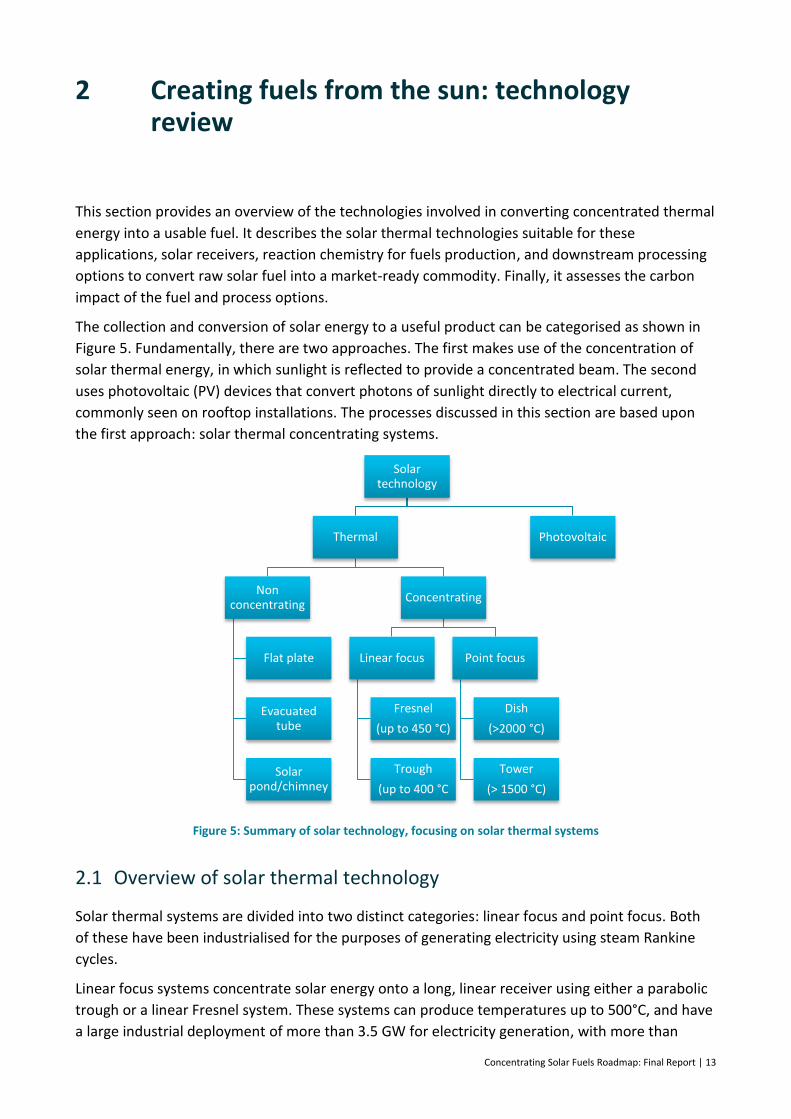
The collection and conversion of solar energy to a useful product can be categorised as shown in
Figure 5. Fundamentally, there are two approaches. The first makes use of the concentration of
solar thermal energy, in which sunlight is reflected to provide a concentrated beam. The second
uses photovoltaic (PV) devices that convert photons of sunlight directly to electrical current,
commonly seen on rooftop installations. The processes discussed in this section are based upon
the first approach: solar thermal concentrating systems.
Figure 5: Summary of solar technology, focusing on solar thermal systems
2.1 Overview of solar thermal technology
Solar thermal systems are divided into two distinct categories: linear focus and point focus. Both
of these have been industrialised for the purposes of generating electricity using steam Rankine
cycles.
Linear focus systems concentrate solar energy onto a long, linear receiver using either a parabolic
trough or a linear Fresnel system. These systems can produce temperatures up to 500°C, and have
a large industrial deployment of more than 3.5 GW for electricity generation, with more than
Solar technology
Thermal
Non concentrating
Flat plate
Evacuated tube
Solar pond/chimney
Concentrating
Linear focus
Fresnel
(up to 450 °C)
Trough
(up to 400 °C
Point focus
Dish
(>2000 °C)
Tower
(> 1500 °C)
Photovoltaic
14 | Concentrating Solar Fuels Roadmap: Final Report
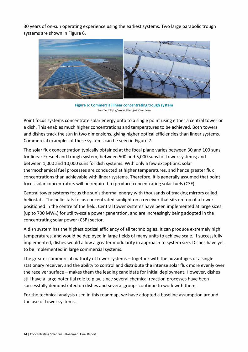
30 years of on-sun operating experience using the earliest systems. Two large parabolic trough
systems are shown in Figure 6.
Figure 6: Commercial linear concentrating trough system Source: http://www.abengoasolar.com
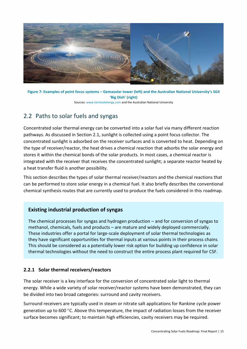
Point focus systems concentrate solar energy onto to a single point using either a central tower or
a dish. This enables much higher concentrations and temperatures to be achieved. Both towers
and dishes track the sun in two dimensions, giving higher optical efficiencies than linear systems.
Commercial examples of these systems can be seen in Figure 7.
The solar flux concentration typically obtained at the focal plane varies between 30 and 100 suns
for linear Fresnel and trough system; between 500 and 5,000 suns for tower systems; and
between 1,000 and 10,000 suns for dish systems. With only a few exceptions, solar
thermochemical fuel processes are conducted at higher temperatures, and hence greater flux
concentrations than achievable with linear systems. Therefore, it is generally assumed that point
focus solar concentrators will be required to produce concentrating solar fuels (CSF).
Central tower systems focus the sun's thermal energy with thousands of tracking mirrors called
heliostats. The heliostats focus concentrated sunlight on a receiver that sits on top of a tower
positioned in the centre of the field. Central tower systems have been implemented at large sizes
(up to 700 MWth) for utility-scale power generation, and are increasingly being adopted in the
concentrating solar power (CSP) sector.
A dish system has the highest optical efficiency of all technologies. It can produce extremely high
temperatures, and would be deployed in large fields of many units to achieve scale. If successfully
implemented, dishes would allow a greater modularity in approach to system size. Dishes have yet
to be implemented in large commercial systems.
The greater commercial maturity of tower systems – together with the advantages of a single
stationary receiver, and the ability to control and distribute the intense solar flux more evenly over
the receiver surface – makes them the leading candidate for initial deployment. However, dishes
still have a large potential role to play, since several chemical reaction processes have been
successfully demonstrated on dishes and several groups continue to work with them.
For the technical analysis used in this roadmap, we have adopted a baseline assumption around
the use of tower systems.
Concentrating Solar Fuels Roadmap: Final Report | 15
Figure 7: Examples of point focus systems – Gemasolar tower (left) and the Australian National University’s SG4
‘Big Dish’ (right) Sources: www.torresolenergy.com and the Australian National University
2.2 Paths to solar fuels and syngas
Concentrated solar thermal energy can be converted into a solar fuel via many different reaction
pathways. As discussed in Section 2.1, sunlight is collected using a point focus collector. The
concentrated sunlight is adsorbed on the receiver surfaces and is converted to heat. Depending on
the type of receiver/reactor, the heat drives a chemical reaction that adsorbs the solar energy and
stores it within the chemical bonds of the solar products. In most cases, a chemical reactor is
integrated with the receiver that receives the concentrated sunlight; a separate reactor heated by
a heat transfer fluid is another possibility.
This section describes the types of solar thermal receiver/reactors and the chemical reactions that
can be performed to store solar energy in a chemical fuel. It also briefly describes the conventional
chemical synthesis routes that are currently used to produce the fuels considered in this roadmap.
Existing industrial production of syngas
The chemical processes for syngas and hydrogen production – and for conversion of syngas to methanol, chemicals, fuels and products – are mature and widely deployed commercially. These industries offer a portal for large-scale deployment of solar thermal technologies as they have significant opportunities for thermal inputs at various points in their process chains. This should be considered as a potentially lower risk option for building up confidence in solar thermal technologies without the need to construct the entire process plant required for CSF.
2.2.1 Solar thermal receivers/reactors
The solar receiver is a key interface for the conversion of concentrated solar light to thermal
energy. While a wide variety of solar receiver/reactor systems have been demonstrated, they can
be divided into two broad categories: surround and cavity receivers.
Surround receivers are typically used in steam or nitrate salt applications for Rankine cycle power
generation up to 600 C. Above this temperature, the impact of radiation losses from the receiver
surface becomes significant; to maintain high efficiencies, cavity receivers may be required.
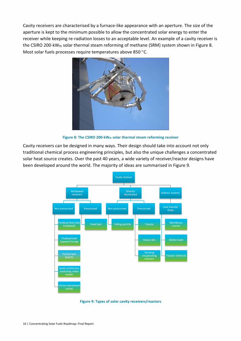
16 | Concentrating Solar Fuels Roadmap: Final Report
Cavity receivers are characterised by a furnace-like appearance with an aperture. The size of the
aperture is kept to the minimum possible to allow the concentrated solar energy to enter the
receiver while keeping re-radiation losses to an acceptable level. An example of a cavity receiver is
the CSIRO 200-kWth solar thermal steam reforming of methane (SRM) system shown in Figure 8.
Most solar fuels processes require temperatures above 850 C.
Figure 8: The CSIRO 200-kWth solar thermal steam reforming receiver
Cavity receivers can be designed in many ways. Their design should take into account not only
traditional chemical process engineering principles, but also the unique challenges a concentrated
solar heat source creates. Over the past 40 years, a wide variety of receiver/reactor designs have
been developed around the world. The majority of ideas are summarised in Figure 9.
Figure 9: Types of solar cavity receivers/reactors
Cavity receiver
Windowed receivers
Non pressurised
Fluidised Bed (side irradiated)
Fluidised bed (upward facing)
Packed bed (batch)
Quasi-continuous (switching redox
mode)
Vortex (windowed cavity)
Pressurised
Fixed bed
Directly illuminated
Non pressurised
Falling particle
Pressurised
Tubular
Rotary kiln
Rotating recuperating
reactors
Indirect systems
Heat transfer fluids
Membrane reactor
Molten bath
Tubular (indirect)

Concentrating Solar Fuels Roadmap: Final Report | 17
Each of the receiver/reactor types is listed below with a typical application. However, for the
techno-economic evaluation in Section 4, all receiver categories were considered with all
categories of reactions.
1. Falling particle receivers are commonly associated with redox systems, where particles are
reduced under intense heat fluxes at up to 1700 C. These receivers employ solid particles
in a falling curtain that is directly irradiated by concentrated sunlight from a field of
heliostats. The particles are required to exhibit high thermal stability; however, this type of
receiver requires solutions for abrasion and high-temperature materials handling.
2. Fluidised bed (side-irradiated) receivers use a bed of small particles which are continually
kept in movement by an upward flow of gases which can be either reactants or additional
inert gases. The side irradiated version is currently being developed in Japan (Kodama et
al., 2002). It has been demonstrated under artificial light conditions for coal gasification.
3. Fluidised bed (upward facing) is a variation on the side-irradiated reactor concept, where
concentrated radiation is introduced from above either though a quartz window or silicon
carbide radiator plate. Recent work has used the concept for redox processes for water
splitting (Gokon et al., 2010).
4. In a membrane reactor (molten media), a selective membrane is used to modify the
chemical equilibrium by separating hydrogen from other reaction products to allow lower
temperature operation (Giaconia et al., 2008). This concept draws on progress made in
molten salt technology widely used in CSP applications to provide thermal energy for
chemical reactions.
5. The molten media bath is a novel approach for the direct thermal cracking of methane or
hydrocarbons to hydrogen and carbon. A high-temperature molten metal (tin or lead) is
used to catalyse the pyrolysis of methane and provide an effective method for recovering
the co-product carbon (Paxman et al., 2014).
6. Packed bed (batch) is a concept for gasification processes. A fixed inventory of
carbonaceous solids is converted to syngas under high-temperature conditions during a
single operating session. Typically, a radiator plate is used rather than a window to
transmit heat to the material to be gasified (Piatkowski et al., 2009).
7. Quasi-continuous (switching redox mode) is the leading method of operating a redox
system for water splitting (Roeb et al., 2011). Here, two reactors can be switched
alternately between reduction and oxidation (water-splitting) modes to provide essentially
continuous production of hydrogen.
8. Rotary kiln involves solarisation of an existing process, where solar energy is directed
within a rotary kiln to facilitate a reaction or drying process. A popular application is
cement manufacture (Gonzalez and Flamant, 2014).
9. Rotating recuperating reactors are a unique approach to the high-temperature
recuperation challenge that redox processes present where solid wheels holding the redox
material are rotated into and then out of the focal region. Use of counter rotating wheels
in close proximity allows recuperation of heat between them (Diver et al., 2010).
10. The tubular (directly irradiated) concept involves the direct irradiation of metal tubes
containing catalysts and/or reactants; for example, the adaptation of the industrial process
for SRM with unique geometry to allow solar capture (Benito et al., 2003).
18 | Concentrating Solar Fuels Roadmap: Final Report
11. The indirectly heated tubular concept (via a heat transfer fluid [HTF]) is a further
adaptation of industrial SRM technology. The HTF transfers heat from the receiver to the
reactor components, and it can also enable thermal storage (McNaughton et al., 2012).
12. Volumetric (windowed, fixed media) receivers are a highly efficient method of solar
capture. Radiation is transmitted through a quartz glass window to allow direct heating of
the reaction (Tamme et al., 2001).
13. Vortex (windowed cavity) pressurised receivers transmit solar energy through a window to
allow energy to be adsorbed directly onto particles moving in a vortex (Hirsch and
Steinfeld, 2004).
Each of the reactor/receiver types listed above has differing advantages and suitabilities for
producing a solar fuel. Selection is strongly dependent on the phase of the reactants and products
for each reaction. Gaseous reactant/product combinations are suitable for flow reactors, such as
tubular and volumetric; reactions involving solids are more suitable for fixed bed switching and
moving bed designs.
Indirect heat transfer systems for solar fuels and process industries
In general, the process heat required for industrial chemical processes is provided by combusting a fuel. The heat input can be readily controlled, allowing it to be used across a wide temperature band. Solar thermal systems can also provide the correct temperature band but require an intermediate heat transfer medium to provide the necessary control.
The vast majority of solar fuel systems that have been demonstrated rely on direct illumination of the reactor to thermally drive the chemical reaction, because of the extreme temperatures involved. Indirect systems use a heat transfer medium to move heat away from the focal area at very high temperatures to a reactor zone, where heat transfer can occur in a controlled and continuous manner. When used in combination with appropriately sized buffers, heat can be supplied 24/7 to the fuel reactor. Taking the heat buffer approach allows the chemical system to operate in a steady-state mode, increasing reliability and allowing product (syngas composition) distributions to be better controlled. This concept has been
extensively proven in CSP plants where 590 C molten salt is used to store heat at efficiencies of 99% for 24/7 electricity generation.
Solar fuels reactors operate above 750 C, with many above 1000 C; consequently, molten salt is not suitable for these systems. Alternative heat transfer media that have been demonstrated in solar thermal systems include gases, such as air, helium or CO2; liquids, such as sodium, tin, carbonate salts, or chloride salts; and solids, such as sand, graphite, silicon carbide and alumina.
Each of the proposed new heat transfer media presents unique challenges. In particular, issues such as stability under thermal cycling conditions, operating temperature ranges, freezing points and pumping/handling capabilities all require novel solutions.
Developing a suite of heat transfer solutions for high-temperature solar thermal systems would allow integration of solar energy into existing fuel synthesis plants, accelerating the uptake of solar-based fuels while demonstrating the technology on a more practical size. It would also open up solar thermal integration options to a much wider industry audience.
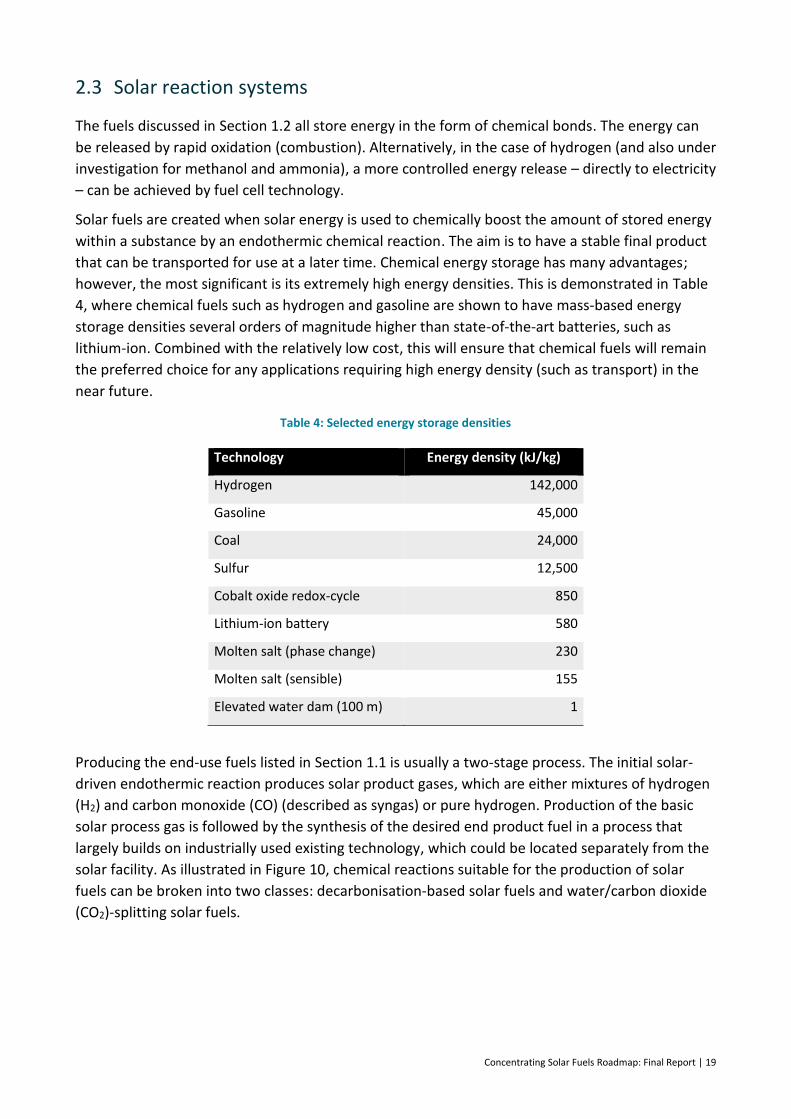
Concentrating Solar Fuels Roadmap: Final Report | 19
2.3 Solar reaction systems
The fuels discussed in Section 1.2 all store energy in the form of chemical bonds. The energy can
be released by rapid oxidation (combustion). Alternatively, in the case of hydrogen (and also under
investigation for methanol and ammonia), a more controlled energy release – directly to electricity
– can be achieved by fuel cell technology.
Solar fuels are created when solar energy is used to chemically boost the amount of stored energy
within a substance by an endothermic chemical reaction. The aim is to have a stable final product
that can be transported for use at a later time. Chemical energy storage has many advantages;
however, the most significant is its extremely high energy densities. This is demonstrated in Table
4, where chemical fuels such as hydrogen and gasoline are shown to have mass-based energy
storage densities several orders of magnitude higher than state-of-the-art batteries, such as
lithium-ion. Combined with the relatively low cost, this will ensure that chemical fuels will remain
the preferred choice for any applications requiring high energy density (such as transport) in the
near future.
Table 4: Selected energy storage densities
Technology Energy density (kJ/kg)
Hydrogen 142,000
Gasoline 45,000
Coal 24,000
Sulfur 12,500
Cobalt oxide redox-cycle 850
Lithium-ion battery 580
Molten salt (phase change) 230
Molten salt (sensible) 155
Elevated water dam (100 m) 1
Producing the end-use fuels listed in Section 1.1 is usually a two-stage process. The initial solar-
driven endothermic reaction produces solar product gases, which are either mixtures of hydrogen
(H2) and carbon monoxide (CO) (described as syngas) or pure hydrogen. Production of the basic
solar process gas is followed by the synthesis of the desired end product fuel in a process that
largely builds on industrially used existing technology, which could be located separately from the
solar facility. As illustrated in Figure 10, chemical reactions suitable for the production of solar
fuels can be broken into two classes: decarbonisation-based solar fuels and water/carbon dioxide
(CO2)-splitting solar fuels.

20 | Concentrating Solar Fuels Roadmap: Final Report
Figure 10: Summary of solar fuel options
Source: Paul Scherrer Institute
Carbon-based solar fuels are similar to common fuels in use today, and are seen as short-term
intermediate solar fuel products that will enable lower-emissions fuels to be produced without the
need for large changes in infrastructure or technology. Because these fuels are produced using
largely known chemical processes already used in industrial settings, they are therefore a more
mature technology option. Short and midterm processes use conventional unprocessed fuels as a
feedstock for energy upgrading of fuels by embedding solar energy into the products.
Hydrogen-based solar fuels will require more development of solar reactor technology, the
required infrastructure to distribute the fuel, and end-use applications (probably fuel cell based).
They are therefore seen as longer-term CSF options, but do offer the promise of truly zero carbon
emission fuels. Other longer-term options look to combined water and CO2-splitting processes.
Common to all solar fuel products is that their production processes will enable subsequent
synthesis of today’s fuels, such as diesel and gasoline, or recognised alternatives such as hydrogen.
2.4 Solar fuels – chemical reaction pathways
Chemical reaction pathways are characterised by endothermic reactions that adsorb thermal
energy to create high-energy fuels. While many candidate reactions are theoretically possible,
substantive screening processes (Kodama and Gokon, 2007) (Abanades et al., 2006) have
identified a select few that have progressed to on-sun experiments.
The chemical reaction pathways and current state-of-the-art developments for solar fuels options
are presented in detail in Appendix A.1, and are summarised below within two high-level groups:
hybrid solar-carbon fuel technologies and carbon-free solar fuels.
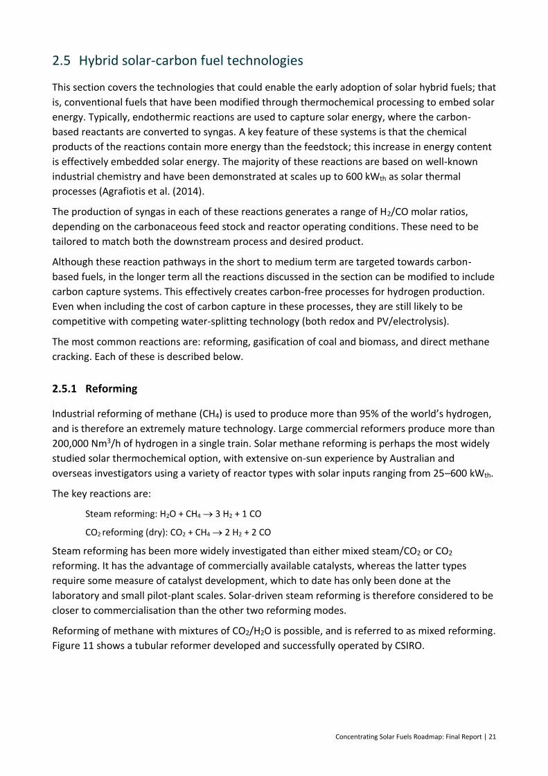
Concentrating Solar Fuels Roadmap: Final Report | 21
2.5 Hybrid solar-carbon fuel technologies
This section covers the technologies that could enable the early adoption of solar hybrid fuels; that
is, conventional fuels that have been modified through thermochemical processing to embed solar
energy. Typically, endothermic reactions are used to capture solar energy, where the carbon-
based reactants are converted to syngas. A key feature of these systems is that the chemical
products of the reactions contain more energy than the feedstock; this increase in energy content
is effectively embedded solar energy. The majority of these reactions are based on well-known
industrial chemistry and have been demonstrated at scales up to 600 kWth as solar thermal
processes (Agrafiotis et al. (2014).
The production of syngas in each of these reactions generates a range of H2/CO molar ratios,
depending on the carbonaceous feed stock and reactor operating conditions. These need to be
tailored to match both the downstream process and desired product.
Although these reaction pathways in the short to medium term are targeted towards carbon-
based fuels, in the longer term all the reactions discussed in the section can be modified to include
carbon capture systems. This effectively creates carbon-free processes for hydrogen production.
Even when including the cost of carbon capture in these processes, they are still likely to be
competitive with competing water-splitting technology (both redox and PV/electrolysis).
The most common reactions are: reforming, gasification of coal and biomass, and direct methane
cracking. Each of these is described below.
2.5.1 Reforming
Industrial reforming of methane (CH4) is used to produce more than 95% of the world’s hydrogen,
and is therefore an extremely mature technology. Large commercial reformers produce more than
200,000 Nm3/h of hydrogen in a single train. Solar methane reforming is perhaps the most widely
studied solar thermochemical option, with extensive on-sun experience by Australian and
overseas investigators using a variety of reactor types with solar inputs ranging from 25–600 kWth.
The key reactions are:
Steam reforming: H2O + CH4 3 H2 + 1 CO
CO2 reforming (dry): CO2 + CH4 2 H2 + 2 CO
Steam reforming has been more widely investigated than either mixed steam/CO2 or CO2
reforming. It has the advantage of commercially available catalysts, whereas the latter types
require some measure of catalyst development, which to date has only been done at the
laboratory and small pilot-plant scales. Solar-driven steam reforming is therefore considered to be
closer to commercialisation than the other two reforming modes.
Reforming of methane with mixtures of CO2/H2O is possible, and is referred to as mixed reforming.
Figure 11 shows a tubular reformer developed and successfully operated by CSIRO.
22 | Concentrating Solar Fuels Roadmap: Final Report
Figure 11: CSIRO 200-kW steam reformer
Over the last 25 years or so there has been an extensive research and development (R&D) effort
worldwide on the solar reforming of methane in all three modes (steam, mixed (H2O/CO2) and dry
CO2), with more than 20 organisations/research groups contributing to the knowledge base. This
work has recently been comprehensively reviewed (Sheu et al., 2015; Simakov et al., 2015;
Agrafiotis et al., 2014).
Outlook for solar reforming
Worldwide, research groups have accumulated hundreds of hours of on-sun experience, making solar-based steam reforming the most demonstrated and advanced solar fuels technology. When combined with the close similarity to industry-based steam reforming, it is a standout as today’s most understood and scalable technology.
Some technical risks remain for steam reforming; namely, quantifying the impact of daily thermal cycling on the receiver reactor components, including both catalysts and the tubular receiver materials. This can be addressed with operational experience in a demonstration facility as a precursor to commercial-scale operations.
2.5.2 Gasification of coal and biomass
The solar steam gasification of coal and other carbonaceous materials, such as biomass, to
produce high-quality syngas is a potentially attractive industrial process. It can be represented by a
generic, simplified net stoichiometric reaction (neglecting the relatively small amounts of sulfur
and nitrogen in the coal and most biomass):
C1HxOy + zH2O + Ash + (1-y-z)H2O → CO +(1-y+x/2)H2 + Ash
The x and y in the feedstock formula are parameters that change according to the material. For
example, black coal is dominated by carbon, while biomass has large amounts of hydrogen and
oxygen (O2). Additionally, if the biomass is derived from a truly renewable and sustainable source,
then gasifying it using solar thermal energy to provide the reaction enthalpy is a potentially
attractive means of producing emission-free syngas. As with solarised coal gasification, using solar

Concentrating Solar Fuels Roadmap: Final Report | 23
energy as the heat source increases both the yield and quality of the syngas, since no internal
oxidation (combustion) processes are required.
Depending on the operating conditions, components such as tars and other volatile organics may
also be formed, especially when using coal.
In conventional autothermal gasification, about 35% of the feed stock is combusted internally with
pure O2 to supply the high-temperature heat for this highly endothermic reaction. This inherently
decreases the hydrogen and CO yield and contaminates the gas with significant amounts of CO2.
When solar energy is used to provide the reaction heat, it offers the following benefits over
conventional autothermal gasification:
It produces a higher yield of syngas (H2 and CO) per unit of feed stock, since no portion of
the feed is combusted for process heat.
It avoids contamination of the syngas with combustion by-products (mainly CO2), and
consequently reduces costly downstream gas cleaning and separation requirements.
It eliminates the need for an air separation plant for pure O2, since steam is the gasifying
agent.
It offers a means of storing intermittent solar energy in a transportable chemical form.
As no portion of the feed stock is combusted for process heat, the chemical energy
content of the feed can be upgraded by up to 33%.
Outlook for solar gasification
The world has significant expertise in traditional gasification processes, and several research groups have adapted it to solar thermal-based systems working at laboratory scale. Pilot-scale demonstrations are limited to two systems at 150 kW (Figure 12) and 500 kW with on-sun operations of tens of hours.
The challenges remaining for solar-driven gasification are common across all of the carbonaceous feed stocks, including biomass materials. These include feeding solids or slurries into the gasification zone and removing solids (ash and unconverted carbon) from the reactor in a controlled manner. Continued work at pilot scale is required to develop a solution for these challenges. However, the potential to utilise low-cost feedstocks to produce low-cost solar fuels makes solar gasification a promising approach.
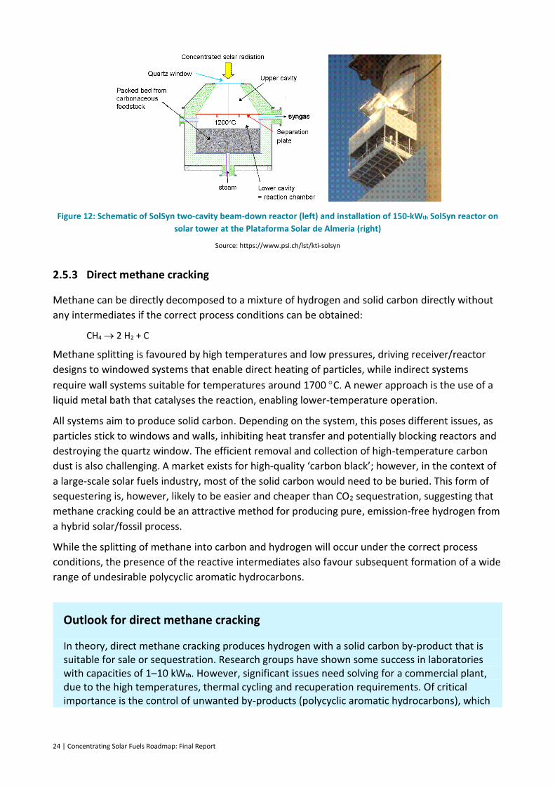
24 | Concentrating Solar Fuels Roadmap: Final Report
Figure 12: Schematic of SolSyn two-cavity beam-down reactor (left) and installation of 150-kWth SolSyn reactor on
solar tower at the Plataforma Solar de Almeria (right)
Source: https://www.psi.ch/lst/kti-solsyn
2.5.3 Direct methane cracking
Methane can be directly decomposed to a mixture of hydrogen and solid carbon directly without
any intermediates if the correct process conditions can be obtained:
CH4 2 H2 + C
Methane splitting is favoured by high temperatures and low pressures, driving receiver/reactor
designs to windowed systems that enable direct heating of particles, while indirect systems
require wall systems suitable for temperatures around 1700 C. A newer approach is the use of a
liquid metal bath that catalyses the reaction, enabling lower-temperature operation.
All systems aim to produce solid carbon. Depending on the system, this poses different issues, as
particles stick to windows and walls, inhibiting heat transfer and potentially blocking reactors and
destroying the quartz window. The efficient removal and collection of high-temperature carbon
dust is also challenging. A market exists for high-quality ‘carbon black’; however, in the context of
a large-scale solar fuels industry, most of the solid carbon would need to be buried. This form of
sequestering is, however, likely to be easier and cheaper than CO2 sequestration, suggesting that
methane cracking could be an attractive method for producing pure, emission-free hydrogen from
a hybrid solar/fossil process.
While the splitting of methane into carbon and hydrogen will occur under the correct process
conditions, the presence of the reactive intermediates also favour subsequent formation of a wide
range of undesirable polycyclic aromatic hydrocarbons.
Outlook for direct methane cracking
In theory, direct methane cracking produces hydrogen with a solid carbon by-product that is suitable for sale or sequestration. Research groups have shown some success in laboratories with capacities of 1–10 kWth. However, significant issues need solving for a commercial plant, due to the high temperatures, thermal cycling and recuperation requirements. Of critical importance is the control of unwanted by-products (polycyclic aromatic hydrocarbons), which
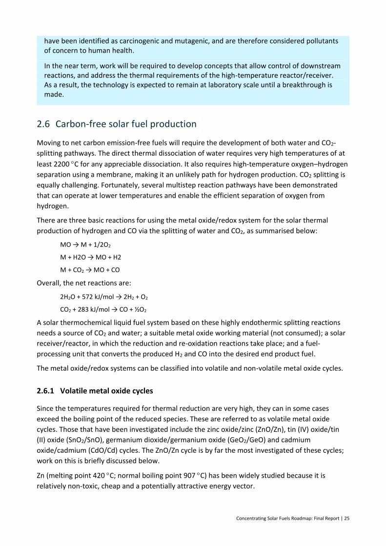
Concentrating Solar Fuels Roadmap: Final Report | 25
have been identified as carcinogenic and mutagenic, and are therefore considered pollutants of concern to human health.
In the near term, work will be required to develop concepts that allow control of downstream reactions, and address the thermal requirements of the high-temperature reactor/receiver. As a result, the technology is expected to remain at laboratory scale until a breakthrough is made.
2.6 Carbon-free solar fuel production
Moving to net carbon emission-free fuels will require the development of both water and CO2-
splitting pathways. The direct thermal dissociation of water requires very high temperatures of at
least 2200 C for any appreciable dissociation. It also requires high-temperature oxygen–hydrogen
separation using a membrane, making it an unlikely path for hydrogen production. CO2 splitting is
equally challenging. Fortunately, several multistep reaction pathways have been demonstrated
that can operate at lower temperatures and enable the efficient separation of oxygen from
hydrogen.
There are three basic reactions for using the metal oxide/redox system for the solar thermal
production of hydrogen and CO via the splitting of water and CO2, as summarised below:
MO → M + 1/2O2
M + H2O → MO + H2
M + CO2 → MO + CO
Overall, the net reactions are:
2H2O + 572 kJ/mol → 2H2 + O2
CO2 + 283 kJ/mol → CO + ½O2
A solar thermochemical liquid fuel system based on these highly endothermic splitting reactions
needs a source of CO2 and water; a suitable metal oxide working material (not consumed); a solar
receiver/reactor, in which the reduction and re-oxidation reactions take place; and a fuel-
processing unit that converts the produced H2 and CO into the desired end product fuel.
The metal oxide/redox systems can be classified into volatile and non-volatile metal oxide cycles.
2.6.1 Volatile metal oxide cycles
Since the temperatures required for thermal reduction are very high, they can in some cases
exceed the boiling point of the reduced species. These are referred to as volatile metal oxide
cycles. Those that have been investigated include the zinc oxide/zinc (ZnO/Zn), tin (IV) oxide/tin
(II) oxide (SnO2/SnO), germanium dioxide/germanium oxide (GeO2/GeO) and cadmium
oxide/cadmium (CdO/Cd) cycles. The ZnO/Zn cycle is by far the most investigated of these cycles;
work on this is briefly discussed below.
Zn (melting point 420 C; normal boiling point 907 C) has been widely studied because it is
relatively non-toxic, cheap and a potentially attractive energy vector.
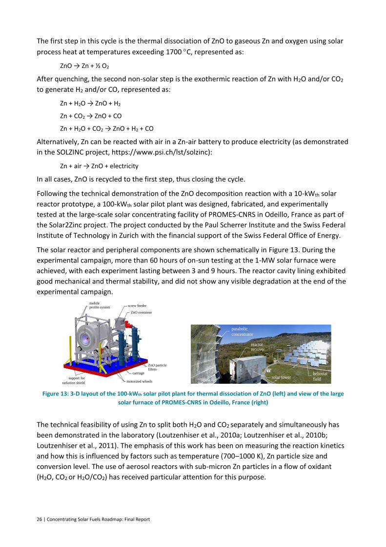
26 | Concentrating Solar Fuels Roadmap: Final Report
The first step in this cycle is the thermal dissociation of ZnO to gaseous Zn and oxygen using solar
process heat at temperatures exceeding 1700 C, represented as:
ZnO → Zn + ½ O2
After quenching, the second non-solar step is the exothermic reaction of Zn with H2O and/or CO2
to generate H2 and/or CO, represented as:
Zn + H2O → ZnO + H2
Zn + CO2 → ZnO + CO
Zn + H2O + CO2 → ZnO + H2 + CO
Alternatively, Zn can be reacted with air in a Zn-air battery to produce electricity (as demonstrated
in the SOLZINC project, https://www.psi.ch/lst/solzinc):
Zn + air → ZnO + electricity
In all cases, ZnO is recycled to the first step, thus closing the cycle.
Following the technical demonstration of the ZnO decomposition reaction with a 10-kWth solar
reactor prototype, a 100-kWth solar pilot plant was designed, fabricated, and experimentally
tested at the large-scale solar concentrating facility of PROMES-CNRS in Odeillo, France as part of
the Solar2Zinc project. The project conducted by the Paul Scherrer Institute and the Swiss Federal
Institute of Technology in Zurich with the financial support of the Swiss Federal Office of Energy.
The solar reactor and peripheral components are shown schematically in Figure 13. During the
experimental campaign, more than 60 hours of on-sun testing at the 1-MW solar furnace were
achieved, with each experiment lasting between 3 and 9 hours. The reactor cavity lining exhibited
good mechanical and thermal stability, and did not show any visible degradation at the end of the
experimental campaign.
Figure 13: 3-D layout of the 100-kWth solar pilot plant for thermal dissociation of ZnO (left) and view of the large
solar furnace of PROMES-CNRS in Odeillo, France (right)
The technical feasibility of using Zn to split both H2O and CO2 separately and simultaneously has
been demonstrated in the laboratory (Loutzenhiser et al., 2010a; Loutzenhiser et al., 2010b;
Loutzenhiser et al., 2011). The emphasis of this work has been on measuring the reaction kinetics
and how this is influenced by factors such as temperature (700–1000 K), Zn particle size and
conversion level. The use of aerosol reactors with sub-micron Zn particles in a flow of oxidant
(H2O, CO2 or H2O/CO2) has received particular attention for this purpose.
mobile profile system
carriage
screw feeder
ZnO container
support for
radiation shield
ZnO particle filters
motorized wheels
heliostat
field
parabolic
concentrator
solar tower
reactor receiver
Concentrating Solar Fuels Roadmap: Final Report | 27
Outlook for volatile metal oxide cycles
Volatile metal oxide cycles have been demonstrated on sun at scales up to 100 kWth and operating times of up to 100 hours in several collaborative European projects. The required
operating temperatures – over 1700 C – are relatively high, but promise the production of a relatively pure metal that can either be used for hydrogen production or directly in a metal-air battery system. Significant challenges must still be solved in the system during the condensation of the metal vapour, where problems such as re-oxidation, side reaction or inappropriate condensation/solidification causing blockages could prevent long-term operation. As a method of storing solar energy, the condensation process also presents difficulties in recuperating heat: this is a vital component to efficient storage of solar energy in the product fuel.
Although volatile metal oxide systems have been developed and operated at reasonable scale on-sun, they have to date only demonstrated very low conversion of solar to stored energy, predominately due to challenges in the condensation stage and recuperation system. In the near term, research will continue to be focused in this area, but there is little likelihood of a commercial-scale application of this technology until workable solutions are developed.
2.6.2 Non-volatile metal oxide cycles
As in the volatile metal oxide splitting cycles, non-volatile metal oxide cycles produce hydrogen
and/or syngas from CO2 and water. The cycled oxide material however always remains in the solid
phase. The general reactions for these cycles can be represented as:
1
d𝑀𝑂𝑥,𝑠𝑜𝑙𝑖𝑑
ℎ𝑒𝑎𝑡→
1
d𝑀𝑂𝑥−d,𝑠𝑜𝑙𝑖𝑑 + ½𝑂2
1
d𝑀𝑂𝑥−d + 𝐶𝑂2
1
d𝑀𝑂𝑥 + 𝐶𝑂
1
d𝑀𝑂𝑥−d + 𝐻2𝑂
1
d𝑀𝑂𝑥 + 𝐻2
where MO = metal oxide. In essence, the reduction reaction results in a partially reduced oxide
with the parameter, ∂, representing the degree of reduction, non-stoichiometry or the reversible
oxygen storage capacity.
Cycles based on iron oxides/ferrites, ceria, perovskites and cobalt ferrite/hercynites are among
those that have been most widely investigated to date, with the ceria cycle receiving the most
attention.
The ceria cycle
The capacity of cerium oxides (Ce2O3/CeO2) to store and release O2 under varying
reduction/oxidation atmospheres has been applied for decades in automobile catalytic convertor
technology. However, it was not until 2006 that a group from French research unit, PROMES,
proposed that a cycle based on this feature of cerium be investigated for solar-driven H2O or CO2-
splitting. The group demonstrated the reduction of CeO2 to Ce2O3 and O2 in a laboratory-scale
solar reactor, followed by oxidation of the Ce2O3 back to CeO2 with steam to produce H2
(Abanades and Flamant, 2006). However, the reduction step was conducted at pressures of 100–
200 mbar and temperatures higher than 1950 C, where the CeO2 was in the molten state.
28 | Concentrating Solar Fuels Roadmap: Final Report
To avoid the CeO2 melting problem, a research group at the California Institute of Technology
(Caltech) proposed a non-stoichiometric cycle, to become known as the ceria cycle, involving the
following reactions (Chueh and Haile, 2009):
CeO2 CeO2-δ + (2-δ) O2 (>1773 K)
CeO2-δ + δH2O CeO2 + δH2 (900–1300 K)
CeO2-δ + δCO2 CeO2 + δCO (900–1300 K)
Work on this cycle has been largely motivated by the following desirable characteristics of the
ceria system:
– CeO2 can be reduced to a significant degree of non-stoichiometry without any phase
changes while retaining a cubic fluorite structure.
– The cycle is capable of faster hydrogen and syngas production kinetics and high selectivity
during the oxidation step.
– Ceria has high thermal stability and maintains its oxygen transfer capability over repeated
cycling between reduction and oxidation, largely due to its fluorite-type structure.
However, the reduction step occurs at temperatures not lower than 1773 K, even when
the O2 partial pressure is as low as 10-5 atm (Chueh et al., 2010; Chueh and Haile, 2010)
Work on the ceria cycle has been conducted primarily in the following areas:
– thermodynamic analyses to examine the effect of key process parameters on overall cycle
performance
– the use of metal dopants to lower the reduction temperature while increasing both the
degree of reduction (non-stoichiometry) and thermal stability/cyclability
– kinetic studies of the reduction and H2O- and/or CO2-splitting steps over a variety of Ce-
based materials
– development of support structures/substrates to deposit ceria on for use in practical
reactor systems in which there is efficient heat and mass transfer to maximise the
performance of the cycle under real solar conditions
– performance testing of the reduction and oxidation steps using laboratory and pilot-scale
reactors integrated with concentrated solar energy.
Outlook for non-volatile metal oxide cycles
Non-volatile metal oxide cycles have seen large growth in the number of research groups investigating them worldwide over the past 10 years. The more established groups are now working on sun with systems up to 100 kWth, and are proposing to scale this up to 750 kWth in 2016. Significantly, theoretical investigations show that conversion of solar energy to stored chemical energy could be higher than 40% (Ermanoski et al., 2014) under ideal conditions. Major challenges remain in achieving these efficiencies, with recuperation, material stability, very low reversible oxygen storage capacity and high inert material loads all keeping current system efficiencies well below 10%.
Concentrating Solar Fuels Roadmap: Final Report | 29
In the near term, the large R&D effort should begin to address these challenges, but we expect that systems suitable for commercial application are still some time away. This option does, however, offer the most likely technology to achieve direct water splitting.
2.6.3 Sulfur cycles
The other promising redox options for water splitting are sulfur-based cycles. Most of these
processes are based on the thermal splitting of sulfuric acid into sulfur dioxide and oxygen. Even
with efficient catalysts, this process requires temperatures above 850 C:
𝐻2𝑆𝑂4 → 𝐻2𝑂 + 𝑆𝑂2 +1
2𝑂2
Sulfur cycles were primarily developed to be coupled with high-temperature heat from nuclear
fission power plants. The main work has been carried out by General Atomics and Westinghouse
in the United States, the European Joint Research Centre in Ispra, Italy and the Japan Atomic
Energy Research Institute (now Japan Atomic Energy Agency). Since no very-high-temperature
reactor is yet in operation, concentrated solar energy is the only available heat source that can be
coupled to the cycles at a large scale. While we note that no industrial scale solar plant has yet
been coupled to a chemical process either, the hurdles to overcome are considered to be lower
than coupling to a very-high-temperature reactor.
A major advantage of the sulfur-based processes is their close relationship to sulfuric acid
production. Therefore, the high-temperature step – namely, the decomposition of sulfuric acid – is
considered to be scalable, although has currently only been demonstrated with a solar input at the
10-kW range.
2.7 Carbothermic solar processes
The carbothermic reduction of metal oxides is an alternative to the very high temperature
dissociation processes discussed in Section 2.6.1. In carbothermic reduction, a carbon source is
used to react with the metal oxide to reduce it to the elemental metal. The carbon source can be
derived from traditional fossil fuels or an appropriate biomass.
The key advantage of the carbothermic approach is that it lowers the temperature for reduction of
the metal oxide by up to 1000 K. In the case of the Zn/ZnO process the operating temperatures for
the reduction are close to 2000 K for the purely solar approach and below 1000 K for the
carbothermic alternative.
As with the processes discussed in Section 2.6.1, the pure metal product produced can be used
either as a reactant in the splitting of water/carbon dioxide or in a metal/air fuel cell depending on
the application required.
While outside the scope of this report, it should be noted that a large number of industrial
processes for the reduction of metals ores incorporate a carbothermic reduction step where the
carbon source is used chemically to reduce the ore as well as being combusted to provide process
heat (e.g. iron production in a blast furnace). These industrial processes also have the potential to
incorporate solar thermal energy to displace the combustion of fossil fuels.
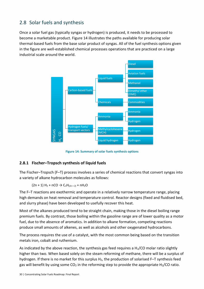
30 | Concentrating Solar Fuels Roadmap: Final Report
2.8 Solar fuels and synthesis
Once a solar fuel gas (typically syngas or hydrogen) is produced, it needs to be processed to
become a marketable product. Figure 14 illustrates the paths available for producing solar
thermal-based fuels from the base solar product of syngas. All of the fuel synthesis options given
in the figure are well-established chemical processes operations that are practiced on a large
industrial scale around the world.
Figure 14: Summary of solar fuels synthesis options
2.8.1 Fischer–Tropsch synthesis of liquid fuels
The Fischer–Tropsch (F–T) process involves a series of chemical reactions that convert syngas into
a variety of alkane hydrocarbon molecules as follows:
(2n + 1) H2 + nCO → CnH(2n + 2) + nH2O
The F–T reactions are exothermic and operate in a relatively narrow temperature range, placing
high demands on heat removal and temperature control. Reactor designs (fixed and fluidised bed,
and slurry phase) have been developed to usefully recover this heat.
Most of the alkanes produced tend to be straight chain, making those in the diesel boiling range
premium fuels. By contrast, those boiling within the gasoline range are of lower quality as a motor
fuel, due to the absence of aromatics. In addition to alkane formation, competing reactions
produce small amounts of alkenes, as well as alcohols and other oxygenated hydrocarbons.
The process requires the use of a catalyst, with the most common being based on the transition
metals iron, cobalt and ruthenium.
As indicated by the above reaction, the synthesis gas feed requires a H2/CO molar ratio slightly
higher than two. When based solely on the steam reforming of methane, there will be a surplus of
hydrogen. If there is no market for this surplus H2, the production of solarised F–T synthesis feed
gas will benefit by using some CO2 in the reforming step to provide the appropriate H2/CO ratio.
SYN
GA
S
H2
CO
Carbon-based fuels
Liquid fuels
Diesel
Aviation fuels
Methanol
Dimethyl ether (DME)
Chemicals Commodities
Hydrogen fuels/ transport vectors
Ammonia
Ammonia
Hydrogen
Methylcyclohexane (MCH)
Hydrogen
Liquid hydrogen Hydrogen
Concentrating Solar Fuels Roadmap: Final Report | 31
Generally, the F–T process is operated in the temperature range 150–300 C. Higher temperatures
lead to faster reactions and higher conversion rates, but also tend to favour the undesired
formation of methane. For this reason, the temperature is usually maintained at the low to middle
part of the range. Increasing pressure leads to higher conversion rates and also favours formation
of long-chain alkanes, both of which are favourable. Typical operating pressures are 20–30 bar.
The F–T process can produce the full range of hydrocarbons, from methane to heavy waxes.
Perhaps the most efficient commercially practiced operation of the F–T process produces waxes
(to minimise the formation of methane), which can subsequently be refined by mild hydro-
cracking to produce liquid transport fuels. Waxes for non-fuel applications can also be valuable
products in limited supply.
The largest scale implementation of F–T technology is in a series of plants operated by Sasol in
South Africa, a country with large coal reserves but little oil. The first coal-based plant commenced
operation in 1952 and there are now three others, based on both coal and natural gas, producing
a variety of synthetic petroleum products, including most of the country’s diesel fuel. Other F–T
plants are located around the world, based largely on natural gas, and more are planned.
F-T technology traditionally involves extremely large plants; an active area of commercial interest
is the development of smaller more modular FT reactors systems.
2.8.2 Methanol
The conversion of synthesis gas to methanol over a Cu/Zn catalyst can be summarised by the
following reactions:
CO + 2H2 ↔ CH3OH ∆H298 K 50 Bar = –90.7 kJ/mol
CO2 + 3H2 ↔ CH3OH + H2O ∆H298 K 50 Bar = –40.9 kJ/mol
Methanol synthesis is exothermic; hence conversion is increased by operating at low temperature
(220–270 C) and high pressure (up to 100 bar). Thermodynamics, reaction mechanism, kinetics
and catalyst properties are discussed in Hansen and Nielsen (2008).
Unlike in F–T synthesis, methanol can be produced from CO2 as well as from CO. Methanol
synthesis gas is characterised by the stoichiometric ratio (H2 – CO2)/ (CO + CO2), often referred to
as the module M. A module value of two defines a stoichiometric synthesis gas for the formation
of methanol by the above reactions.
Methanol production involves the steps of synthesis gas preparation, methanol synthesis
(including gas compression) and purification (Aasberg-Petersen et al., 2013).
The challenge in the design of a methanol synthesis reactor is to remove the heat of reaction
efficiently and economically – that is, at as high a temperature as possible – while at the same
time equilibrating the synthesis reactions at low temperature to maximise the per-pass
conversion. Three designs of methanol synthesis reactors have been used.
Unlike F–T synthesis, methanol synthesis is highly selective, with carbon selectivity to methanol
being as high as 99.9%. This is remarkable, since the by-products are thermodynamically more
favoured than methanol itself. Typical by-products include dimethyl ether (DME), higher alcohols,
other oxygenates and trace amounts of acids and aldehydes.

32 | Concentrating Solar Fuels Roadmap: Final Report
This is a very mature technology, with 2013 global methanol production reaching 65 million
tonnes, primarily for chemical feedstock uses, rather than fuel. By volume, methanol is one of the
top five chemical commodities shipped around the world each year. It can and has been used
directly as a fuel or in combination with gasoline and diesel.
Single-train methanol plants with capacities of greater than 5,000 tonnes/day of methanol are in
operation today with plants double this capacity being planned for the future. Ferrostaal have a
5000 tonnes/day plant in Trinidad1.
Overall, methanol plants are lower in capital cost and available in smaller sizes than F-T plants.
2.8.3 Dimethyl ether
DME, also known as methoxymethane (CH3OCH3), is primarily produced by the catalytic
dehydration of methanol using a silica-alumina catalyst:
2CH3OH ↔ (CH3)2O + H2O ∆H298K = –23.3 kJ/mol
This is a two-step (indirect) synthesis that starts with methanol synthesis (e.g. from natural gas)
followed by methanol dehydration. The same process can be based any type of fossil fuel, organic
waste or biomass.
Alternatively, DME can be produced through direct synthesis from syngas, using a dual-catalyst
system that permits both methanol synthesis and dehydration in the same process unit, with no
methanol isolation and purification. By eliminating the intermediate methanol synthesis stage, the
process licensors claim efficiency advantages and cost benefits (Sai Prasad et al., 2008). This one-
step process is endothermic and could in principle be solar driven, although no investigation of
this appears to have been reported to date.
DME is the sole fuel product. It is a promising fuel for diesel engines, owing to its high cetane
number (55, compared with 40–53 for most diesel fuels) and clean-burning attributes. Only
moderate modifications are needed to convert a diesel engine to burn DME. It can also be used in
adapted spark ignition (petrol) engines (30% DME/70% liquefied petroleum gas) and gas turbines.
The combustion of this simple short-carbon-chain compound results in very low emissions of
particulate matter, oxides of nitrogen (NOx) and CO. For these reasons, as well as being sulfur-free,
DME meets even the most stringent emission regulations in Europe, the United States and Japan.
Both the one-step and two-step processes are commercially available. Currently, the two-step
process is more widely applied, since it is relatively simple and has lower start-up costs.
2.8.4 Methanol to gasoline
Syngas can be converted to gasoline using methanol as an intermediate. This process is far more
selective than the F–T synthesis, but is restricted to producing gasoline rather than diesel fuel.
1 http://www.ferrostaal.com/de/petrochemicals/methanol/
Concentrating Solar Fuels Roadmap: Final Report | 33
Methanol can be converted to hydrocarbons boiling in the gasoline range by reactions occurring
over a synthetic zeolite catalyst (ZSM 5) thus:
2CH3OH → (CH3)2O + H2O → light olefins → higher olefins + n/iso-paraffins + aromatics + naphthenes
As can be seen from the reaction scheme, methanol is first dehydrated to DME. The equilibrium
mixture of methanol, DME and water is then converted to light olefins (C2–C4). A final reaction
step leads to a mixture of higher olefins, n/iso-paraffins, aromatics and naphthenes, to produce a
gasoline that needs only minor further refining to attain the quality of unleaded premium gasoline.
In the methanol-to-gasoline section of the process, methanol is vaporised and fed into the DME
reactor, where it is catalytically equilibrated over a special alumina catalyst to a mixture of DME,
methanol and water. The reaction takes place at a reactor inlet temperature of 310–320 C and a
pressure of around 26 bar. Approximately 15–20% of the exothermic heat of reaction is released
in this first step, which is controlled by chemical equilibrium. The DME reactor effluent is mixed
with recycle gas to moderate the temperature rise over the second reactor, and then fed to the
ZSM 5 reactor, the inlet temperature of which is 350–370 C.
The most notable commercial application of this technology is the synfuel plant commissioned at
Motonui, Taranaki, New Zealand in 1985. This plant, which included two 2,200 tonnes per day
methanol production units, was capable of producing 570,000 tonnes per annum of gasoline
(Maiden, 1987). It was successfully operated for about 10 years before the methanol-to-gasoline
section was shut down and the plant was converted to chemical-grade methanol production.
Mobil also developed a modified version of its process in an effort to produce diesel. This process,
referred to as the Mobil olefins to gasoline and diesel process, was tested in a Mobil refinery in
1981 to demonstrate the technology. Other processes that may merit evaluation for the
conversion of methanol to liquid fuels in a solar context include the methanol to olefins (MTO)
process developed by UOP/Norsk Hydro and Haldor Topsoe’s Topsoe Improved Gasoline Synthesis
(TIGASTM) process (Keil, 1999). A 15,500 barrel per day plant using the TIGASTM process is planned
in Turkmenistan.
2.8.5 Ammonia
Ammonia is a major industrial chemical produced in massive quantities worldwide primarily for
the production of fertilisers and explosives. There is increasing interest, particularly in Japan, in
using ammonia as both a liquid fuel and hydrogen storage medium. Worldwide production of
ammonia was 198 million tonnes in 2012, and is predicted to increase by about 35 million tonnes
by 2019. It is traded and shipped around the world.
The Haber–Bosch ammonia synthesis process, which is used to produce the vast majority of
ammonia today, involves the reaction of nitrogen from the air with hydrogen derived mainly from
natural gas (methane) via the following reversible and exothermic reaction:
N2 + 3H2 ↔ 2NH3(g) ∆H298K = –92 kJmol-1
In existing commercial plants, ammonia synthesis feed gas is produced by a combination of
primary (steam) reforming and secondary (catalytic partial oxidation with air) reforming of
methane. After high and low-temperature water-gas shift, CO2 removal and methanation to
convert any residual CO (an ammonia synthesis catalyst poison) to methane, this produces a gas
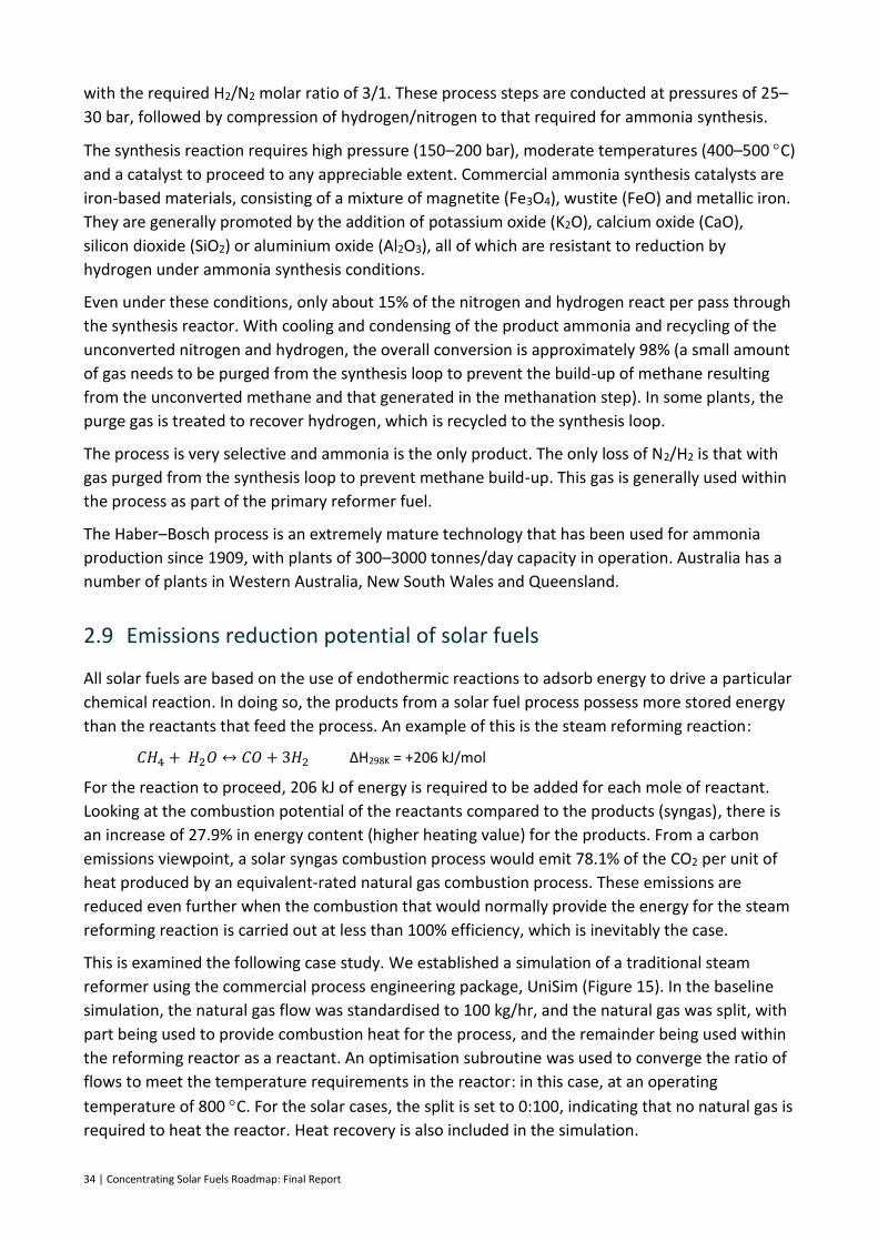
34 | Concentrating Solar Fuels Roadmap: Final Report
with the required H2/N2 molar ratio of 3/1. These process steps are conducted at pressures of 25–
30 bar, followed by compression of hydrogen/nitrogen to that required for ammonia synthesis.
The synthesis reaction requires high pressure (150–200 bar), moderate temperatures (400–500 C)
and a catalyst to proceed to any appreciable extent. Commercial ammonia synthesis catalysts are
iron-based materials, consisting of a mixture of magnetite (Fe3O4), wustite (FeO) and metallic iron.
They are generally promoted by the addition of potassium oxide (K2O), calcium oxide (CaO),
silicon dioxide (SiO2) or aluminium oxide (Al2O3), all of which are resistant to reduction by
hydrogen under ammonia synthesis conditions.
Even under these conditions, only about 15% of the nitrogen and hydrogen react per pass through
the synthesis reactor. With cooling and condensing of the product ammonia and recycling of the
unconverted nitrogen and hydrogen, the overall conversion is approximately 98% (a small amount
of gas needs to be purged from the synthesis loop to prevent the build-up of methane resulting
from the unconverted methane and that generated in the methanation step). In some plants, the
purge gas is treated to recover hydrogen, which is recycled to the synthesis loop.
The process is very selective and ammonia is the only product. The only loss of N2/H2 is that with
gas purged from the synthesis loop to prevent methane build-up. This gas is generally used within
the process as part of the primary reformer fuel.
The Haber–Bosch process is an extremely mature technology that has been used for ammonia
production since 1909, with plants of 300–3000 tonnes/day capacity in operation. Australia has a
number of plants in Western Australia, New South Wales and Queensland.
2.9 Emissions reduction potential of solar fuels
All solar fuels are based on the use of endothermic reactions to adsorb energy to drive a particular
chemical reaction. In doing so, the products from a solar fuel process possess more stored energy
than the reactants that feed the process. An example of this is the steam reforming reaction:
𝐶𝐻4 + 𝐻2𝑂 ↔ 𝐶𝑂 + 3𝐻2 ∆H298K = +206 kJ/mol
For the reaction to proceed, 206 kJ of energy is required to be added for each mole of reactant.
Looking at the combustion potential of the reactants compared to the products (syngas), there is
an increase of 27.9% in energy content (higher heating value) for the products. From a carbon
emissions viewpoint, a solar syngas combustion process would emit 78.1% of the CO2 per unit of
heat produced by an equivalent-rated natural gas combustion process. These emissions are
reduced even further when the combustion that would normally provide the energy for the steam
reforming reaction is carried out at less than 100% efficiency, which is inevitably the case.
This is examined the following case study. We established a simulation of a traditional steam
reformer using the commercial process engineering package, UniSim (Figure 15). In the baseline
simulation, the natural gas flow was standardised to 100 kg/hr, and the natural gas was split, with
part being used to provide combustion heat for the process, and the remainder being used within
the reforming reactor as a reactant. An optimisation subroutine was used to converge the ratio of
flows to meet the temperature requirements in the reactor: in this case, at an operating
temperature of 800 C. For the solar cases, the split is set to 0:100, indicating that no natural gas is
required to heat the reactor. Heat recovery is also included in the simulation.

Concentrating Solar Fuels Roadmap: Final Report | 35
Figure 15: UniSim simulation of a natural-gas-fired primary steam reformer

36 | Concentrating Solar Fuels Roadmap: Final Report
Three cases were considered. The first is typical of ammonia production, where the primary
reformer products are fed to a secondary reformer at the operating temperature of the primary
reformer. In this case there is no heat recovery required, and hence up to 33% of the natural gas
feed is diverted to combustion to fire the reactor. The second considers a case where the
downstream processing is driving towards hydrogen production, so the heat recovery is limited to
a temperature suitable for the water-gas shift reaction to occur. In the final case, syngas is the
desired product, so we were able to maximise the heat recovery, and therefore minimise the
required diversion of feed gas.
The results are summarised in Table 5. It follows logically that in the first case, where solar thermal
energy can make the greatest contribution, that the emissions savings are greatest. All are higher
than the 21.9% reduction suggested by the simple change in HHV alone based on the reaction.
Table 5: Emissions reduction potential of three scenarios for steam reforming
Description Ammonia 1 –
traditional reforming/
no heat recovery
Ammonia 2 – solar
reforming/no heat recovery
Hydrogen 1 – traditional reforming/
heat recovery to 450 °C (to
feed HTWGS reactor)
Hydrogen 2 –solar
reforming/ heat
recovery to 450 °C (to
feed HTWGS reactor)
Syngas 1 –traditional reforming/
heat recovery to 150 °C (to maximise
energy capture)
Syngas 2 – solar
reforming/ heat
recovery to 150 °C (to maximise
energy capture)
CO2 emissions (kg/hr)
260.86 260.86 260.86 260.86 260.86 260.86
Energy output as syngas (MW)
0.963 1.455 1.025 1.455 1.07 1.455
Solar input (MW)
– 0.565 – 0.469 – 0.394
Solar to chemical efficiency (%)
– 35.6 – 43.6 – 51.8
Heat recovery temp (oC)
800 800 450 450 150 150
Emission kg CO2/MW
270 179 254 179 243 179
Emissions reduction, %
– 33.8 – 29.6 – 26.5
HTWGS = high-temperature water-gas shift
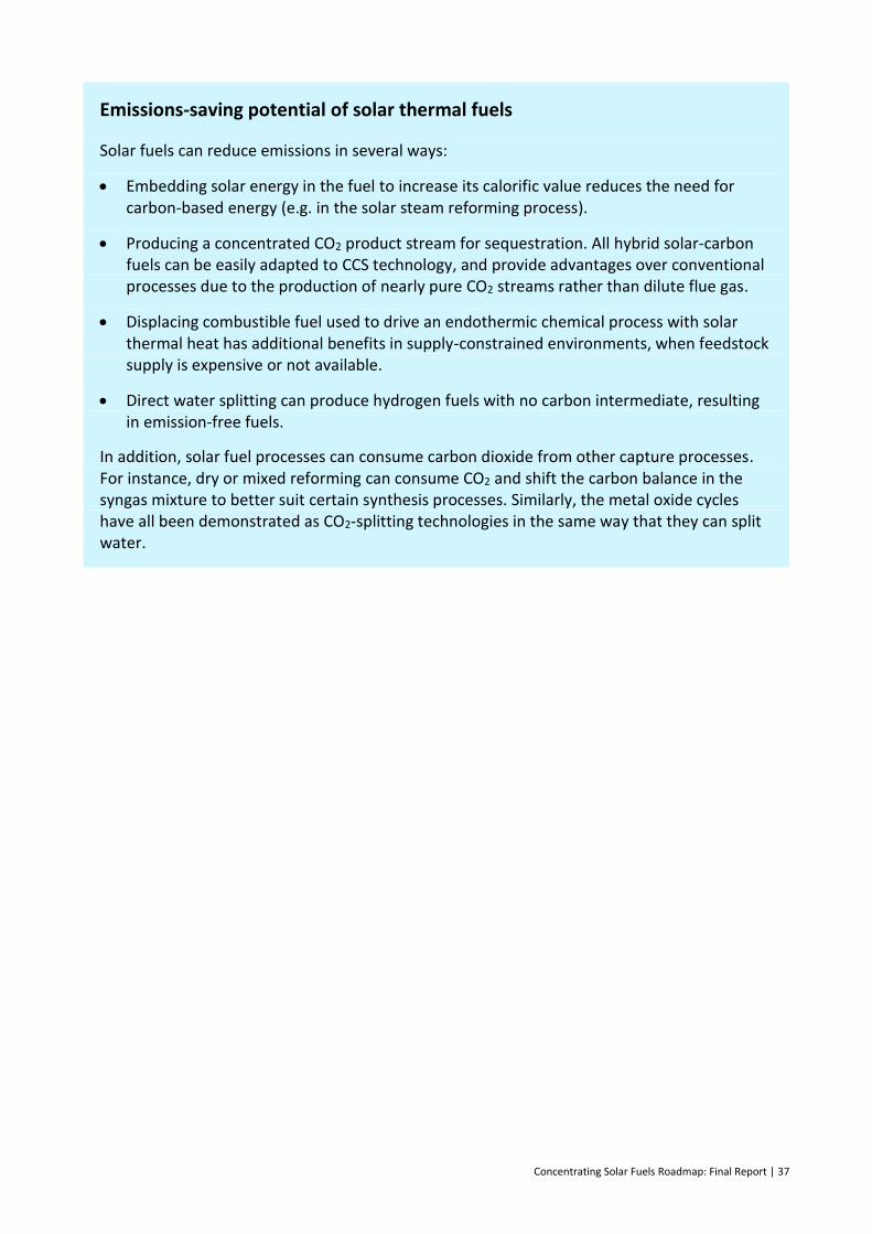
Concentrating Solar Fuels Roadmap: Final Report | 37
Emissions-saving potential of solar thermal fuels
Solar fuels can reduce emissions in several ways:
Embedding solar energy in the fuel to increase its calorific value reduces the need for carbon-based energy (e.g. in the solar steam reforming process).
Producing a concentrated CO2 product stream for sequestration. All hybrid solar-carbon fuels can be easily adapted to CCS technology, and provide advantages over conventional processes due to the production of nearly pure CO2 streams rather than dilute flue gas.
Displacing combustible fuel used to drive an endothermic chemical process with solar thermal heat has additional benefits in supply-constrained environments, when feedstock supply is expensive or not available.
Direct water splitting can produce hydrogen fuels with no carbon intermediate, resulting in emission-free fuels.
In addition, solar fuel processes can consume carbon dioxide from other capture processes. For instance, dry or mixed reforming can consume CO2 and shift the carbon balance in the syngas mixture to better suit certain synthesis processes. Similarly, the metal oxide cycles have all been demonstrated as CO2-splitting technologies in the same way that they can split water.
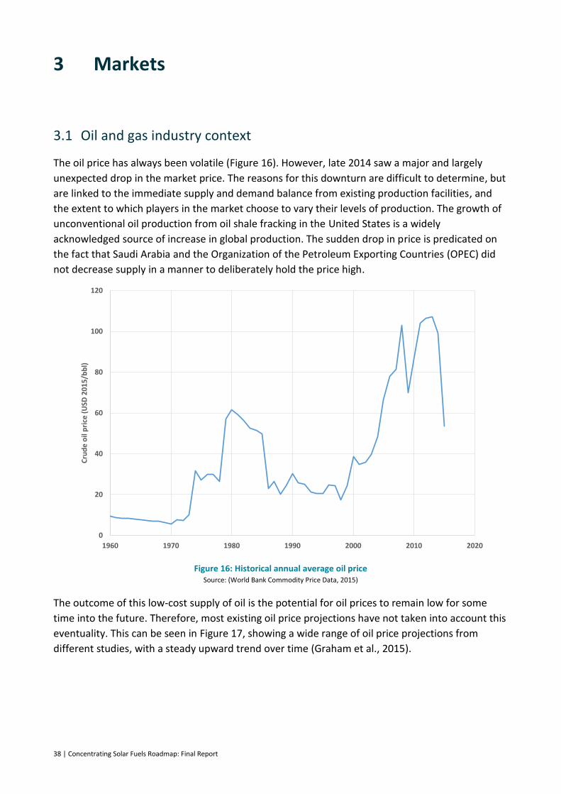
38 | Concentrating Solar Fuels Roadmap: Final Report
3 Markets
3.1 Oil and gas industry context
The oil price has always been volatile (Figure 16). However, late 2014 saw a major and largely
unexpected drop in the market price. The reasons for this downturn are difficult to determine, but
are linked to the immediate supply and demand balance from existing production facilities, and
the extent to which players in the market choose to vary their levels of production. The growth of
unconventional oil production from oil shale fracking in the United States is a widely
acknowledged source of increase in global production. The sudden drop in price is predicated on
the fact that Saudi Arabia and the Organization of the Petroleum Exporting Countries (OPEC) did
not decrease supply in a manner to deliberately hold the price high.
Figure 16: Historical annual average oil price Source: (World Bank Commodity Price Data, 2015)
The outcome of this low-cost supply of oil is the potential for oil prices to remain low for some
time into the future. Therefore, most existing oil price projections have not taken into account this
eventuality. This can be seen in Figure 17, showing a wide range of oil price projections from
different studies, with a steady upward trend over time (Graham et al., 2015).
0
20
40
60
80
100
120
1960 1970 1980 1990 2000 2010 2020
Cru
de
oil
pri
ce (
USD
20
15
/bb
l)
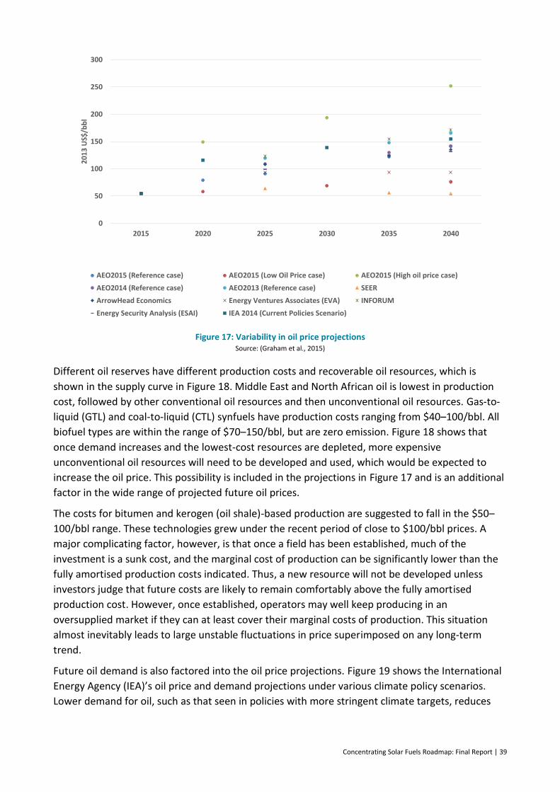
Concentrating Solar Fuels Roadmap: Final Report | 39
Figure 17: Variability in oil price projections Source: (Graham et al., 2015)
Different oil reserves have different production costs and recoverable oil resources, which is
shown in the supply curve in Figure 18. Middle East and North African oil is lowest in production
cost, followed by other conventional oil resources and then unconventional oil resources. Gas-to-
liquid (GTL) and coal-to-liquid (CTL) synfuels have production costs ranging from $40–100/bbl. All
biofuel types are within the range of $70–150/bbl, but are zero emission. Figure 18 shows that
once demand increases and the lowest-cost resources are depleted, more expensive
unconventional oil resources will need to be developed and used, which would be expected to
increase the oil price. This possibility is included in the projections in Figure 17 and is an additional
factor in the wide range of projected future oil prices.
The costs for bitumen and kerogen (oil shale)-based production are suggested to fall in the $50–
100/bbl range. These technologies grew under the recent period of close to $100/bbl prices. A
major complicating factor, however, is that once a field has been established, much of the
investment is a sunk cost, and the marginal cost of production can be significantly lower than the
fully amortised production costs indicated. Thus, a new resource will not be developed unless
investors judge that future costs are likely to remain comfortably above the fully amortised
production cost. However, once established, operators may well keep producing in an
oversupplied market if they can at least cover their marginal costs of production. This situation
almost inevitably leads to large unstable fluctuations in price superimposed on any long-term
trend.
Future oil demand is also factored into the oil price projections. Figure 19 shows the International
Energy Agency (IEA)’s oil price and demand projections under various climate policy scenarios.
Lower demand for oil, such as that seen in policies with more stringent climate targets, reduces
0
50
100
150
200
250
300
2015 2020 2025 2030 2035 2040
20
13
US$
/bb
l
AEO2015 (Reference case) AEO2015 (Low Oil Price case) AEO2015 (High oil price case)
AEO2014 (Reference case) AEO2013 (Reference case) SEER
ArrowHead Economics Energy Ventures Associates (EVA) INFORUM
Energy Security Analysis (ESAI) IEA 2014 (Current Policies Scenario)
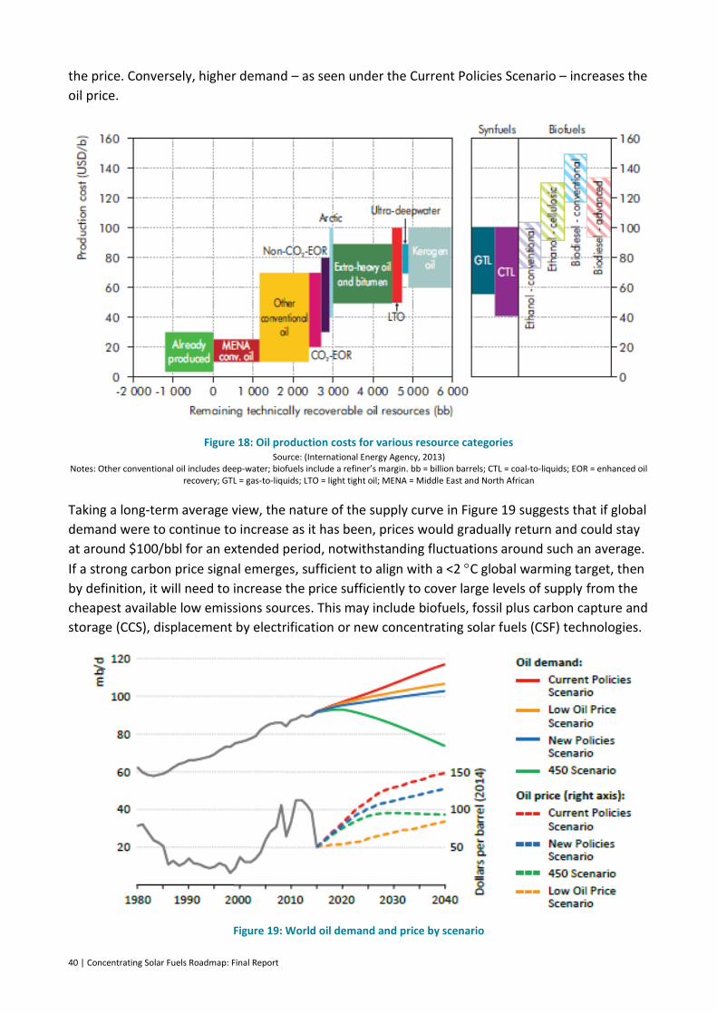
40 | Concentrating Solar Fuels Roadmap: Final Report
the price. Conversely, higher demand – as seen under the Current Policies Scenario – increases the
oil price.
Figure 18: Oil production costs for various resource categories Source: (International Energy Agency, 2013)
Notes: Other conventional oil includes deep-water; biofuels include a refiner’s margin. bb = billion barrels; CTL = coal-to-liquids; EOR = enhanced oil recovery; GTL = gas-to-liquids; LTO = light tight oil; MENA = Middle East and North African
Taking a long-term average view, the nature of the supply curve in Figure 19 suggests that if global
demand were to continue to increase as it has been, prices would gradually return and could stay
at around $100/bbl for an extended period, notwithstanding fluctuations around such an average.
If a strong carbon price signal emerges, sufficient to align with a <2 C global warming target, then
by definition, it will need to increase the price sufficiently to cover large levels of supply from the
cheapest available low emissions sources. This may include biofuels, fossil plus carbon capture and
storage (CCS), displacement by electrification or new concentrating solar fuels (CSF) technologies.
Figure 19: World oil demand and price by scenario
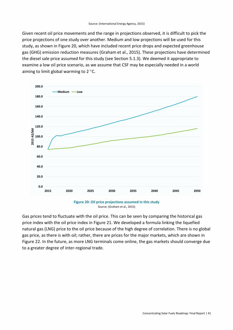
Concentrating Solar Fuels Roadmap: Final Report | 41
Source: (International Energy Agency, 2015)
Given recent oil price movements and the range in projections observed, it is difficult to pick the
price projections of one study over another. Medium and low projections will be used for this
study, as shown in Figure 20, which have included recent price drops and expected greenhouse
gas (GHG) emission reduction measures (Graham et al., 2015). These projections have determined
the diesel sale price assumed for this study (see Section 5.1.3). We deemed it appropriate to
examine a low oil price scenario, as we assume that CSF may be especially needed in a world
aiming to limit global warming to 2 C.
Figure 20: Oil price projections assumed in this study Source: (Graham et al., 2015)
Gas prices tend to fluctuate with the oil price. This can be seen by comparing the historical gas
price index with the oil price index in Figure 21. We developed a formula linking the liquefied
natural gas (LNG) price to the oil price because of the high degree of correlation. There is no global
gas price, as there is with oil; rather, there are prices for the major markets, which are shown in
Figure 22. In the future, as more LNG terminals come online, the gas markets should converge due
to a greater degree of inter-regional trade.
0.0
20.0
40.0
60.0
80.0
100.0
120.0
140.0
160.0
180.0
200.0
2015 2020 2025 2030 2035 2040 2045 2050
20
15
A$
/bb
l
Medium Low
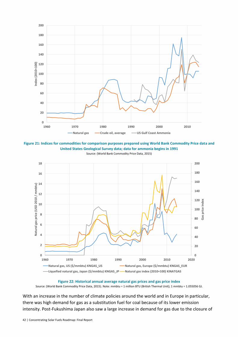
42 | Concentrating Solar Fuels Roadmap: Final Report
Figure 21: Indices for commodities for comparison purposes prepared using World Bank Commodity Price data and
United States Geological Survey data; data for ammonia begins in 1991 Source: (World Bank Commodity Price Data, 2015)
Figure 22: Historical annual average natural gas prices and gas price index Source: (World Bank Commodity Price Data, 2015). Note: mmbtu = 1 million BTU (British Thermal Unit); 1 mmbtu = 1.055056 GJ.
With an increase in the number of climate policies around the world and in Europe in particular,
there was high demand for gas as a substitution fuel for coal because of its lower emission
intensity. Post-Fukushima Japan also saw a large increase in demand for gas due to the closure of
0
20
40
60
80
100
120
140
160
180
200
1960 1970 1980 1990 2000 2010
Ind
ex (
201
0=10
0)
Natural gas Crude oil, average US Gulf Coast Ammonia
0
20
40
60
80
100
120
140
160
180
200
0
2
4
6
8
10
12
14
16
18
1960 1970 1980 1990 2000 2010 2020
Gas
pri
ce in
dex
Nat
ura
l gas
pri
ce (
USD
20
10
/ m
mb
tu)
Natural gas, US ($/mmbtu) KNGAS_US Natural gas, Europe ($/mmbtu) KNGAS_EUR
Liquefied natural gas, Japan ($/mmbtu) KNGAS_JP Natural gas index (2010=100) KiNATGAS

Concentrating Solar Fuels Roadmap: Final Report | 43
nuclear plants. The high oil price also drives countries that are still using oil for significant levels of
power generation to move to gas. These factors have also helped to keep gas prices high until
recently (International Energy Agency, 2012; International Energy Agency, 2015).
Lately, gas prices around the world have fallen, which is due to several factors. An increased
supply of LNG has come online since the shortfall, demand has fallen somewhat for gas as overall
world economic growth has slowed, and the oil price has dropped. Also, once LNG facilities are
brought online in the United States, the price should fall (or stay low) again for gas. This is because
the United States will be a low-cost supplier (blue line in Figure 22), given the low price of gas in
their domestic market.
In Australia, the west coast has historically had higher domestic gas prices than the east coast. The
west coast’s LNG facilities forced a linkage between international LNG market prices and the
domestic market, even though Western Australia has a reservation policy that requires producers
to reserve 15% of natural gas production for domestic use. The east coast was not exposed to this
international market until late 2014, when LNG facilities in Gladstone, Queensland, first exported
LNG to Asia (van Vonderen, 2015). There was a great deal of speculation that this would also
increase domestic gas prices on the east coast. However, because of the fall in the oil price – and
thus, gas price globally – domestic prices have so far not increased as much as expected.
Global gas prices influence commodity prices downstream where gas is used as a feedstock for
their production. In this study, such commodities of interest are methanol, ammonia and
hydrogen. Since these commodities represent export opportunities for Australia, their future price
will be linked to an Asian LNG price. The IEA’s World Energy Outlook (WEO) has provided
projections out to the year 2040 of the LNG price in Japan, as shown in Figure 23. The forecast
prices are lower than previous WEOs; this reflects the downturn in the oil price since the last
projections were made.
Figure 23: Projected liquefied natural gas (LNG) price into Japan
0
5
10
15
20
25
2015 2020 2025 2030 2035 2040
Pro
ject
ed
LN
G p
rice
in J
apan
(A
UD
20
15
/GJ)
Current policies New policies 450ppm Low oil price

44 | Concentrating Solar Fuels Roadmap: Final Report
Source: (International Energy Agency, 2015)
3.2 Existing commodities markets
The majority of CSF under consideration in this roadmap are currently produced from fossil fuels
and traded internationally; methanol, petroleum liquids and ammonia in particular. This means
that in the early stages of a CFS industry, they could be sold into an existing market with a known
market price. The potential advantage of CSF over existing, conventionally produced commodities
is their more stable production cost, because the capital cost outweighs the feedstock cost and
the capital repayments are known in advance. This reduces the variability in the final fuel price.
Basic market data on each CSF commodity are shown in Table 6.
Table 6: Relevant commodity data for concentrating solar fuels options
Product Market price traditional
units
Market price AUD
2015/GJ
Global production
Application Issues
Methanol $386/t 20a 61 Mt/year Chemical synthesis (plastics), fuel blending
Toxicity, hygroscopic
Dimethyl ether (DME)
$0.54/gallon 6b 4 Mt/year Fuel (LPG blend), propellant
Volatile, requires engine modification for use in transport
Petroleum liquids
$1.10/L 20–21c 4,000 Mt/year
Transport, lubrication Plant scale, source of oil
Hydrogen $3/kg 21d 50 Mt/year Ammonia production, refining, methanol production, fuel cells (vehicles)
Disruptive, storage, transport
Ammonia $740/t 40e 180 Mt/year Fertiliser, industrial and transport
Competition with food industry for fertiliser, currently not used as a fuel, expensive to convert to hydrogen
a December 2015 Asia–Pacific Price. Available from: https://www.methanex.com/our-business/pricing b United States Energy Information Administration, 2015. U.S. average wholesale propane. Available from: https://www.eia.gov/petroleum/heatingoilpropane/. [Accessed 29 November 2015]. c Australian Institute of Petroleum, 2015. Terminal Gate Prices [Online]. http://www.aip.com.au/pricing/tgp/index.htm. [Accessed 29 November 2015]. d ACIL Tasman and Parsons Brinckerhoff, 2003. National Hydrogen Study. Available online at: http://www.industry.gov.au/Energy/Documents/national_hydro_study.pdf. e 2014 annual United States Gulf Coast price, from Apodaca, L.E., 2015. Nitrogen (fixed)-ammonia, US Geological Survey, Mineral Commodity Summaries, January 2015. Available online at: minerals.usgs.gov/minerals/pubs/commodity/nitrogen/mcs-2015-nitro.pdf.
In Table 6, methanol and ammonia in particular are classified as high-value chemicals, the current
main use of which is in the chemical industry. As a whole, this industry is a large user of global
energy. In 2010, it was responsible for 10% of global energy demand (largely petrochemical/oil)
and 7% of global GHG emissions (IEA, 2013b). The ammonia and methanol production processes
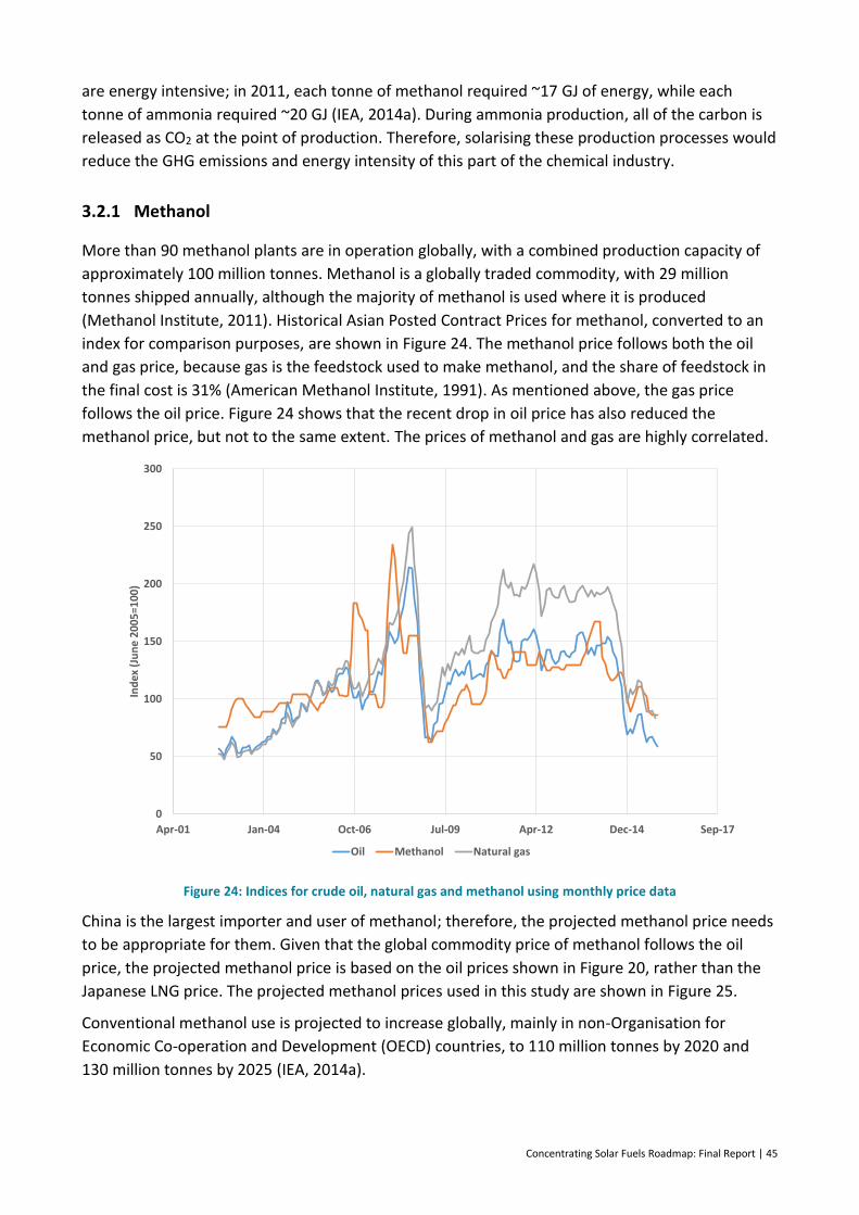
Concentrating Solar Fuels Roadmap: Final Report | 45
are energy intensive; in 2011, each tonne of methanol required ~17 GJ of energy, while each
tonne of ammonia required ~20 GJ (IEA, 2014a). During ammonia production, all of the carbon is
released as CO2 at the point of production. Therefore, solarising these production processes would
reduce the GHG emissions and energy intensity of this part of the chemical industry.
3.2.1 Methanol
More than 90 methanol plants are in operation globally, with a combined production capacity of
approximately 100 million tonnes. Methanol is a globally traded commodity, with 29 million
tonnes shipped annually, although the majority of methanol is used where it is produced
(Methanol Institute, 2011). Historical Asian Posted Contract Prices for methanol, converted to an
index for comparison purposes, are shown in Figure 24. The methanol price follows both the oil
and gas price, because gas is the feedstock used to make methanol, and the share of feedstock in
the final cost is 31% (American Methanol Institute, 1991). As mentioned above, the gas price
follows the oil price. Figure 24 shows that the recent drop in oil price has also reduced the
methanol price, but not to the same extent. The prices of methanol and gas are highly correlated.
Figure 24: Indices for crude oil, natural gas and methanol using monthly price data
China is the largest importer and user of methanol; therefore, the projected methanol price needs
to be appropriate for them. Given that the global commodity price of methanol follows the oil
price, the projected methanol price is based on the oil prices shown in Figure 20, rather than the
Japanese LNG price. The projected methanol prices used in this study are shown in Figure 25.
Conventional methanol use is projected to increase globally, mainly in non-Organisation for
Economic Co-operation and Development (OECD) countries, to 110 million tonnes by 2020 and
130 million tonnes by 2025 (IEA, 2014a).
0
50
100
150
200
250
300
Apr-01 Jan-04 Oct-06 Jul-09 Apr-12 Dec-14 Sep-17
Ind
ex (
Jun
e 2
00
5=1
00
)
Oil Methanol Natural gas
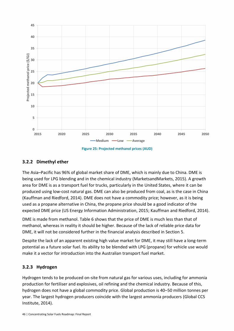
46 | Concentrating Solar Fuels Roadmap: Final Report
Figure 25: Projected methanol prices (AUD)
3.2.2 Dimethyl ether
The Asia–Pacific has 96% of global market share of DME, which is mainly due to China. DME is
being used for LPG blending and in the chemical industry (MarketsandMarkets, 2015). A growth
area for DME is as a transport fuel for trucks, particularly in the United States, where it can be
produced using low-cost natural gas. DME can also be produced from coal, as is the case in China
(Kauffman and Riedford, 2014). DME does not have a commodity price; however, as it is being
used as a propane alternative in China, the propane price should be a good indicator of the
expected DME price (US Energy Information Administration, 2015; Kauffman and Riedford, 2014).
DME is made from methanol. Table 6 shows that the price of DME is much less than that of
methanol, whereas in reality it should be higher. Because of the lack of reliable price data for
DME, it will not be considered further in the financial analysis described in Section 5.
Despite the lack of an apparent existing high value market for DME, it may still have a long-term
potential as a future solar fuel. Its ability to be blended with LPG (propane) for vehicle use would
make it a vector for introduction into the Australian transport fuel market.
3.2.3 Hydrogen
Hydrogen tends to be produced on-site from natural gas for various uses, including for ammonia
production for fertiliser and explosives, oil refining and the chemical industry. Because of this,
hydrogen does not have a global commodity price. Global production is 40–50 million tonnes per
year. The largest hydrogen producers coincide with the largest ammonia producers (Global CCS
Institute, 2014).
0
5
10
15
20
25
30
35
40
45
2015 2020 2025 2030 2035 2040 2045 2050
Pro
ject
ed
met
han
ol p
rice
($
/GJ)
Medium Low Average

Concentrating Solar Fuels Roadmap: Final Report | 47
Hydrogen production prices are available, but these should be considered as the lowest possible
price, because no transport is involved. The current price at a refinery in Australia is estimated to
be from $2–5/kg ($14–35/GJ), but this will fluctuate with the natural gas price, since gas is used as
a hydrogen production feedstock (ACIL Tasman and Parsons Brinckerhoff, 2003; Dolan et al.,
2015).
A study examining potential hydrogen sale prices in Japan, where the hydrogen is sourced from
overseas, has calculated a range of hydrogen prices (Kameyama et al., 2010). The prices depend
on the method of hydrogen production and transport to Japan. The study found the price of
hydrogen to be ~$6/kg ($42/GJ), when produced using a fossil fuel process with CCS and transport
of hydrogen in liquid form. The price of hydrogen produced from renewables (mainly wind
energy), as liquid hydrogen, was ~$8/kg ($56/GJ). However, using the same fossil fuel method of
production but transporting as a liquid organic hydride reduced the price to ~$3/kg ($21/GJ).
These prices are expected to increase in the future, because ~80% of the cost of hydrogen is based
on the gas price (Dolan et al., 2015). Because the hydrogen is assumed to be exported to Asia, the
Japanese LNG price trajectory is the most appropriate to use for future gas prices. The projected
prices are shown in Figure 26, where the average price is shown as a blue line, and the ‘new
policies’ and ‘low oil price’ LNG price trajectories form the upper and lower bounds. These
projections assume that the capital and operating components of the price of hydrogen
production remain fixed over time. Thus, the proportional contribution of the gas price to the
hydrogen price increases as the gas price rises. The projection begins in 2020, because the
hydrogen prices expected in Japan were aspirational and not current (Kameyama et al., 2010).
Figure 26: Projected prices of liquid hydrogen imported into Japan. 1 kg = 0.142 GJ
0
2
4
6
8
10
12
14
16
2020 2025 2030 2035 2040 2045 2050
Pro
ject
ed
pri
ce o
f liq
uid
hyd
roge
n (
$/k
g)

48 | Concentrating Solar Fuels Roadmap: Final Report
3.2.4 Ammonia
Currently, 80% of ammonia production is for either urea or other fertilisers. The remainder is used
for industrial purposes, such as explosives (PotashCorp, 2015). However, ammonia is now also
used in conjunction with diesel in modern trucks to comply with European emission standards.
Ammonia demand has grown by ~2% per year over the last 10 years. Some have suggested that
the ammonia commodity price will reduce or remain stable as new production capacity comes
online in the United States, which can take advantage of low natural gas feedstock prices (Hazmat
Management, 2014). Of the 180 million tonnes of ammonia produced per year, approximately
22 million is traded. The United States and Asia are the largest importers of ammonia (PotashCorp,
2015).
Ammonia tends to be produced for local use, but unlike hydrogen, it is already sold as a global
commodity. The 2014 average United States gulf coast commodity price was US$530/short tonne
($40/GJ) (Apodaca, 2015). In this study, ammonia is considered as an export commodity to Asia,
whether to be used as a source of hydrogen or combusted directly. Approximately 55% of the cost
of producing ammonia conventionally is due to natural gas as feedstock (Sun et al., 2013). To
project the price of ammonia into the future, we have used the approach for projecting the price
of hydrogen: except in this case, 65% of the existing price will remain fixed throughout time, and
the remaining portion (due to natural gas) will vary with the LNG price. The projected
conventionally produced ammonia price begins in 2015 using the current price data. The resultant
trajectories are shown in Figure 27.
Figure 27: Projected price of ammonia
Ammonia production is projected to increase to 200 million tonnes by 2020, and 210 million
tonnes by 2025 (IEA, 2014a).
0
5
10
15
20
25
30
35
40
45
2015 2020 2025 2030 2035 2040 2045 2050
Pro
ject
ed
am
mo
nia
pri
ce (
$/G
J)
New Policies Low Oil Price Average
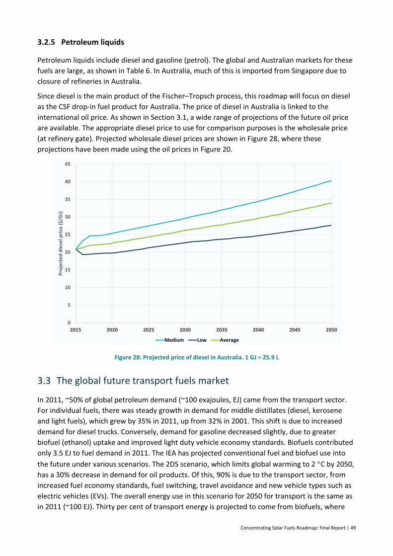
Concentrating Solar Fuels Roadmap: Final Report | 49
3.2.5 Petroleum liquids
Petroleum liquids include diesel and gasoline (petrol). The global and Australian markets for these
fuels are large, as shown in Table 6. In Australia, much of this is imported from Singapore due to
closure of refineries in Australia.
Since diesel is the main product of the Fischer–Tropsch process, this roadmap will focus on diesel
as the CSF drop-in fuel product for Australia. The price of diesel in Australia is linked to the
international oil price. As shown in Section 3.1, a wide range of projections of the future oil price
are available. The appropriate diesel price to use for comparison purposes is the wholesale price
(at refinery gate). Projected wholesale diesel prices are shown in Figure 28, where these
projections have been made using the oil prices in Figure 20.
Figure 28: Projected price of diesel in Australia. 1 GJ = 25.9 L
3.3 The global future transport fuels market
In 2011, ~50% of global petroleum demand (~100 exajoules, EJ) came from the transport sector.
For individual fuels, there was steady growth in demand for middle distillates (diesel, kerosene
and light fuels), which grew by 35% in 2011, up from 32% in 2001. This shift is due to increased
demand for diesel trucks. Conversely, demand for gasoline decreased slightly, due to greater
biofuel (ethanol) uptake and improved light duty vehicle economy standards. Biofuels contributed
only 3.5 EJ to fuel demand in 2011. The IEA has projected conventional fuel and biofuel use into
the future under various scenarios. The 2DS scenario, which limits global warming to 2 C by 2050,
has a 30% decrease in demand for oil products. Of this, 90% is due to the transport sector, from
increased fuel economy standards, fuel switching, travel avoidance and new vehicle types such as
electric vehicles (EVs). The overall energy use in this scenario for 2050 for transport is the same as
in 2011 (~100 EJ). Thirty per cent of transport energy is projected to come from biofuels, where
0
5
10
15
20
25
30
35
40
45
2015 2020 2025 2030 2035 2040 2045 2050
Pro
ject
ed
die
sel p
rice
($
/GJ)
Medium Low Average
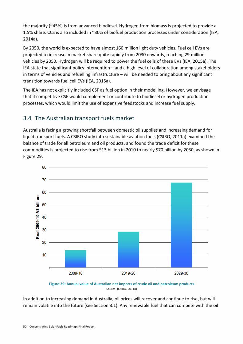
50 | Concentrating Solar Fuels Roadmap: Final Report
the majority (~45%) is from advanced biodiesel. Hydrogen from biomass is projected to provide a
1.5% share. CCS is also included in ~30% of biofuel production processes under consideration (IEA,
2014a).
By 2050, the world is expected to have almost 160 million light duty vehicles. Fuel cell EVs are
projected to increase in market share quite rapidly from 2030 onwards, reaching 29 million
vehicles by 2050. Hydrogen will be required to power the fuel cells of these EVs (IEA, 2015a). The
IEA state that significant policy intervention – and a high level of collaboration among stakeholders
in terms of vehicles and refuelling infrastructure – will be needed to bring about any significant
transition towards fuel cell EVs (IEA, 2015a).
The IEA has not explicitly included CSF as fuel option in their modelling. However, we envisage
that if competitive CSF would complement or contribute to biodiesel or hydrogen production
processes, which would limit the use of expensive feedstocks and increase fuel supply.
3.4 The Australian transport fuels market
Australia is facing a growing shortfall between domestic oil supplies and increasing demand for
liquid transport fuels. A CSIRO study into sustainable aviation fuels (CSIRO, 2011a) examined the
balance of trade for all petroleum and oil products, and found the trade deficit for these
commodities is projected to rise from $13 billion in 2010 to nearly $70 billion by 2030, as shown in
Figure 29.
Figure 29: Annual value of Australian net imports of crude oil and petroleum products Source: (CSIRO, 2011a)
In addition to increasing demand in Australia, oil prices will recover and continue to rise, but will
remain volatile into the future (see Section 3.1). Any renewable fuel that can compete with the oil
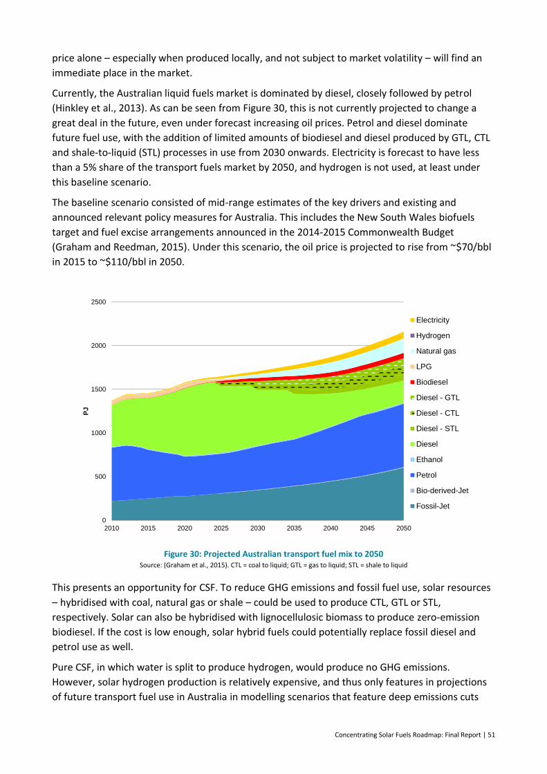
Concentrating Solar Fuels Roadmap: Final Report | 51
price alone – especially when produced locally, and not subject to market volatility – will find an
immediate place in the market.
Currently, the Australian liquid fuels market is dominated by diesel, closely followed by petrol
(Hinkley et al., 2013). As can be seen from Figure 30, this is not currently projected to change a
great deal in the future, even under forecast increasing oil prices. Petrol and diesel dominate
future fuel use, with the addition of limited amounts of biodiesel and diesel produced by GTL, CTL
and shale-to-liquid (STL) processes in use from 2030 onwards. Electricity is forecast to have less
than a 5% share of the transport fuels market by 2050, and hydrogen is not used, at least under
this baseline scenario.
The baseline scenario consisted of mid-range estimates of the key drivers and existing and
announced relevant policy measures for Australia. This includes the New South Wales biofuels
target and fuel excise arrangements announced in the 2014-2015 Commonwealth Budget
(Graham and Reedman, 2015). Under this scenario, the oil price is projected to rise from ~$70/bbl
in 2015 to ~$110/bbl in 2050.
Figure 30: Projected Australian transport fuel mix to 2050 Source: (Graham et al., 2015). CTL = coal to liquid; GTL = gas to liquid; STL = shale to liquid
This presents an opportunity for CSF. To reduce GHG emissions and fossil fuel use, solar resources
– hybridised with coal, natural gas or shale – could be used to produce CTL, GTL or STL,
respectively. Solar can also be hybridised with lignocellulosic biomass to produce zero-emission
biodiesel. If the cost is low enough, solar hybrid fuels could potentially replace fossil diesel and
petrol use as well.
Pure CSF, in which water is split to produce hydrogen, would produce no GHG emissions.
However, solar hydrogen production is relatively expensive, and thus only features in projections
of future transport fuel use in Australia in modelling scenarios that feature deep emissions cuts
0
500
1000
1500
2000
2500
2010 2015 2020 2025 2030 2035 2040 2045 2050
PJ
Electricity
Hydrogen
Natural gas
LPG
Biodiesel
Diesel - GTL
Diesel - CTL
Diesel - STL
Diesel
Ethanol
Petrol
Bio-derived-Jet
Fossil-Jet
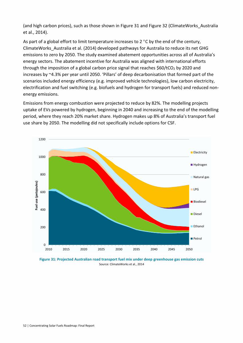
52 | Concentrating Solar Fuels Roadmap: Final Report
(and high carbon prices), such as those shown in Figure 31 and Figure 32 (ClimateWorks_Australia
et al., 2014).
As part of a global effort to limit temperature increases to 2 C by the end of the century,
ClimateWorks_Australia et al. (2014) developed pathways for Australia to reduce its net GHG
emissions to zero by 2050. The study examined abatement opportunities across all of Australia’s
energy sectors. The abatement incentive for Australia was aligned with international efforts
through the imposition of a global carbon price signal that reaches $60/tCO2 by 2020 and
increases by ~4.3% per year until 2050. ‘Pillars’ of deep decarbonisation that formed part of the
scenarios included energy efficiency (e.g. improved vehicle technologies), low carbon electricity,
electrification and fuel switching (e.g. biofuels and hydrogen for transport fuels) and reduced non-
energy emissions.
Emissions from energy combustion were projected to reduce by 82%. The modelling projects
uptake of EVs powered by hydrogen, beginning in 2040 and increasing to the end of the modelling
period, where they reach 20% market share. Hydrogen makes up 8% of Australia’s transport fuel
use share by 2050. The modelling did not specifically include options for CSF.
Figure 31: Projected Australian road transport fuel mix under deep greenhouse gas emission cuts Source: ClimateWorks et al., 2014
0
200
400
600
800
1000
1200
2010 2015 2020 2025 2030 2035 2040 2045 2050
Electricity
Hydrogen
Natural gas
LPG
Biodiesel
Diesel
Ethanol
Petrol
Fue
l use
(p
eta
jou
les)

Concentrating Solar Fuels Roadmap: Final Report | 53
Figure 32: Projected Australian road transport engine types in vehicle kilometres travelled Source: ClimateWorks et al., 2014
The substitution of one fuel with another does not only depend on the cost of producing the fuel.
Because of the large scale required for a CTL or conventional GTL plant, a large capital investment
is required of more than $15 billion, with typical plant sizes greater than 50,000 barrels per day. A
great deal of uncertainty in the oil price (Figure 16) increases the risk involved in any future large
capital investment in alternative fuel technologies, because the returns on that investment are
more uncertain. This higher risk attracts a higher interest/discount rate, which can put off
investors and thus delay these projects. This could potentially be an issue for any large-scale solar
hybrid fuels project.
Blended fuels as a transition to a low emissions future
CSF technologies can produce a range of fuels that can substitute directly for conventional liquid fuels, such as diesel and gasoline, although these may not be the lowest cost CSF to produce. Alternative products such as methanol can be blended with gasoline at up to 20% by volume without adversely affecting fuel quality. Proving this to be the case will be important for society’s acceptance of CSF methanol blends, and a necessary precursor to establishing fuel mandates. Other potential blends to which CSF can contribute up to 20% are DME in LPG, and hydrogen in natural gas pipeline systems.
It is clear from the experience with ethanol that the introduction of new fuels into the market needs to be managed carefully. While it is claimed that ethanol blends up to 10% have no detrimental impact on conventional internal combustion engines, much resistance remains in the community to E10 fuel, with the perception that it is somehow worse than normal unleaded petrol. Introducing new alternative blends of renewable fuels would need to be carefully managed to avoid similar pushback.
0
50
100
150
200
250
300
350
400
2010 2015 2020 2025 2030 2035 2040 2045 2050
Fuel cell
Electric
Plug-inhybridelectric
Hybrid
InternalcombustionV
eh
icle
kilo
me
tre
s tr
ave
lled
(b
illio
n)
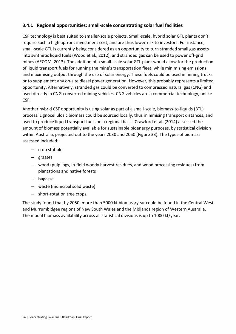
54 | Concentrating Solar Fuels Roadmap: Final Report
3.4.1 Regional opportunities: small-scale concentrating solar fuel facilities
CSF technology is best suited to smaller-scale projects. Small-scale, hybrid solar GTL plants don’t
require such a high upfront investment cost, and are thus lower risk to investors. For instance,
small-scale GTL is currently being considered as an opportunity to turn stranded small gas assets
into synthetic liquid fuels (Wood et al., 2012), and stranded gas can be used to power off-grid
mines (AECOM, 2013). The addition of a small-scale solar GTL plant would allow for the production
of liquid transport fuels for running the mine’s transportation fleet, while minimising emissions
and maximising output through the use of solar energy. These fuels could be used in mining trucks
or to supplement any on-site diesel power generation. However, this probably represents a limited
opportunity. Alternatively, stranded gas could be converted to compressed natural gas (CNG) and
used directly in CNG-converted mining vehicles. CNG vehicles are a commercial technology, unlike
CSF.
Another hybrid CSF opportunity is using solar as part of a small-scale, biomass-to-liquids (BTL)
process. Lignocellulosic biomass could be sourced locally, thus minimising transport distances, and
used to produce liquid transport fuels on a regional basis. Crawford et al. (2014) assessed the
amount of biomass potentially available for sustainable bioenergy purposes, by statistical division
within Australia, projected out to the years 2030 and 2050 (Figure 33). The types of biomass
assessed included:
– crop stubble
– grasses
– wood (pulp logs, in-field woody harvest residues, and wood processing residues) from
plantations and native forests
– bagasse
– waste (municipal solid waste)
– short-rotation tree crops.
The study found that by 2050, more than 5000 kt biomass/year could be found in the Central West
and Murrumbidgee regions of New South Wales and the Midlands region of Western Australia.
The modal biomass availability across all statistical divisions is up to 1000 kt/year.
Concentrating Solar Fuels Roadmap: Final Report | 55
Figure 33: Spatial representation of the potential total biomass (kt) available annually in each of Australia’s 60
statistical divisions in 2050 Source: (Crawford et al., 2014)
As an example, (Hayward et al., 2015; Murphy et al., 2015) have shown that substantial
lignocellulosic biomass resources are in the Fitzroy region of Queensland (north of the Sunshine
Coast and south of Townsville), which were not included in Crawford et al. (2014). These resources
are regrowth, essentially woody weeds, which are a problem for the cattle graziers in the region.
In addition, there are opportunities for the establishment of short-rotation tree plantations. These
would consist of coppicing species of native trees that can be harvested and regrown in 10-year
cycles. The average cost of using both types of biomass has been estimated to be $80/dry-t
($4.44/GJ). While this cost is of the same order of magnitude as the cost of residues, regrowth is
more plentiful (Rodriguez et al., 2011).
The Fitzroy region, which includes the major industrial port of Gladstone, also has a high direct
normal irradiance (DNI) (Figure 34). It was found that the Fitzroy region could supply more than
5250 kt/year of lignocellulosic biomass, which could be used to generate 1.3 GL/year of
hydrocarbon fuels. A fuels industry of such a large scale would have a positive impact on regional
development. Hayward et al. (2015) estimated that this scale of industry would result in $7 billion
of investment, return $400–500 million to the biomass suppliers and farmers, and potentially
generate 3800 jobs at the conversion facilities and more than 6000 indirect jobs in the region.
These figures are for BTL conversion facilities, without solar.
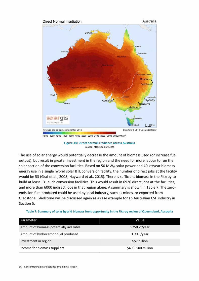
56 | Concentrating Solar Fuels Roadmap: Final Report
Figure 34: Direct normal irradiance across Australia Source: http://solargis.info
The use of solar energy would potentially decrease the amount of biomass used (or increase fuel
output), but result in greater investment in the region and the need for more labour to run the
solar section of the conversion facilities. Based on 50 MWth solar power and 40 kt/year biomass
energy use in a single hybrid solar BTL conversion facility, the number of direct jobs at the facility
would be 53 (Graf et al., 2008; Hayward et al., 2015). There is sufficient biomass in the Fitzroy to
build at least 131 such conversion facilities. This would result in 6926 direct jobs at the facilities,
and more than 6000 indirect jobs in that region alone. A summary is shown in Table 7. The zero-
emission fuel produced could be used by local industry, such as mines, or exported from
Gladstone. Gladstone will be discussed again as a case example for an Australian CSF industry in
Section 5.
Table 7: Summary of solar hybrid biomass fuels opportunity in the Fitzroy region of Queensland, Australia
Parameter Value
Amount of biomass potentially available 5250 kt/year
Amount of hydrocarbon fuel produced 1.3 GJ/year
Investment in region >$7 billion
Income for biomass suppliers $400–500 million
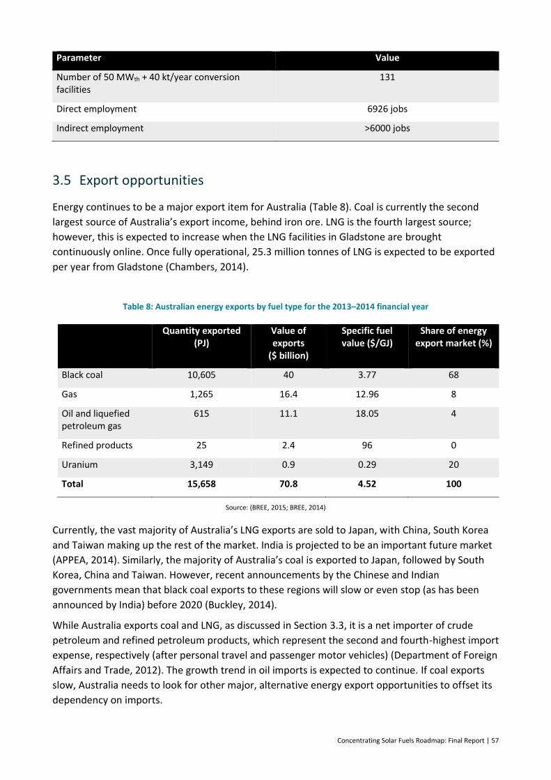
Concentrating Solar Fuels Roadmap: Final Report | 57
Parameter Value
Number of 50 MWth + 40 kt/year conversion facilities
131
Direct employment 6926 jobs
Indirect employment >6000 jobs
3.5 Export opportunities
Energy continues to be a major export item for Australia (Table 8). Coal is currently the second
largest source of Australia’s export income, behind iron ore. LNG is the fourth largest source;
however, this is expected to increase when the LNG facilities in Gladstone are brought
continuously online. Once fully operational, 25.3 million tonnes of LNG is expected to be exported
per year from Gladstone (Chambers, 2014).
Table 8: Australian energy exports by fuel type for the 2013–2014 financial year
Fuel Quantity exported (PJ)
Value of exports
($ billion)
Specific fuel value ($/GJ)
Share of energy export market (%)
Black coal 10,605 40 3.77 68
Gas 1,265 16.4 12.96 8
Oil and liquefied petroleum gas
615 11.1 18.05 4
Refined products 25 2.4 96 0
Uranium 3,149 0.9 0.29 20
Total 15,658 70.8 4.52 100
Source: (BREE, 2015; BREE, 2014)
Currently, the vast majority of Australia’s LNG exports are sold to Japan, with China, South Korea
and Taiwan making up the rest of the market. India is projected to be an important future market
(APPEA, 2014). Similarly, the majority of Australia’s coal is exported to Japan, followed by South
Korea, China and Taiwan. However, recent announcements by the Chinese and Indian
governments mean that black coal exports to these regions will slow or even stop (as has been
announced by India) before 2020 (Buckley, 2014).
While Australia exports coal and LNG, as discussed in Section 3.3, it is a net importer of crude
petroleum and refined petroleum products, which represent the second and fourth-highest import
expense, respectively (after personal travel and passenger motor vehicles) (Department of Foreign
Affairs and Trade, 2012). The growth trend in oil imports is expected to continue. If coal exports
slow, Australia needs to look for other major, alternative energy export opportunities to offset its
dependency on imports.
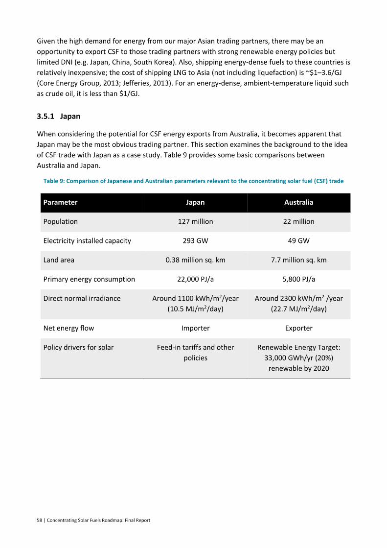
58 | Concentrating Solar Fuels Roadmap: Final Report
Given the high demand for energy from our major Asian trading partners, there may be an
opportunity to export CSF to those trading partners with strong renewable energy policies but
limited DNI (e.g. Japan, China, South Korea). Also, shipping energy-dense fuels to these countries is
relatively inexpensive; the cost of shipping LNG to Asia (not including liquefaction) is ~$1–3.6/GJ
(Core Energy Group, 2013; Jefferies, 2013). For an energy-dense, ambient-temperature liquid such
as crude oil, it is less than $1/GJ.
3.5.1 Japan
When considering the potential for CSF energy exports from Australia, it becomes apparent that
Japan may be the most obvious trading partner. This section examines the background to the idea
of CSF trade with Japan as a case study. Table 9 provides some basic comparisons between
Australia and Japan.
Table 9: Comparison of Japanese and Australian parameters relevant to the concentrating solar fuel (CSF) trade
Parameter Japan Australia
Population 127 million 22 million
Electricity installed capacity 293 GW 49 GW
Land area 0.38 million sq. km 7.7 million sq. km
Primary energy consumption 22,000 PJ/a 5,800 PJ/a
Direct normal irradiance Around 1100 kWh/m2/year
(10.5 MJ/m2/day)
Around 2300 kWh/m2 /year
(22.7 MJ/m2/day)
Net energy flow Importer Exporter
Policy drivers for solar Feed-in tariffs and other
policies
Renewable Energy Target:
33,000 GWh/yr (20%)
renewable by 2020
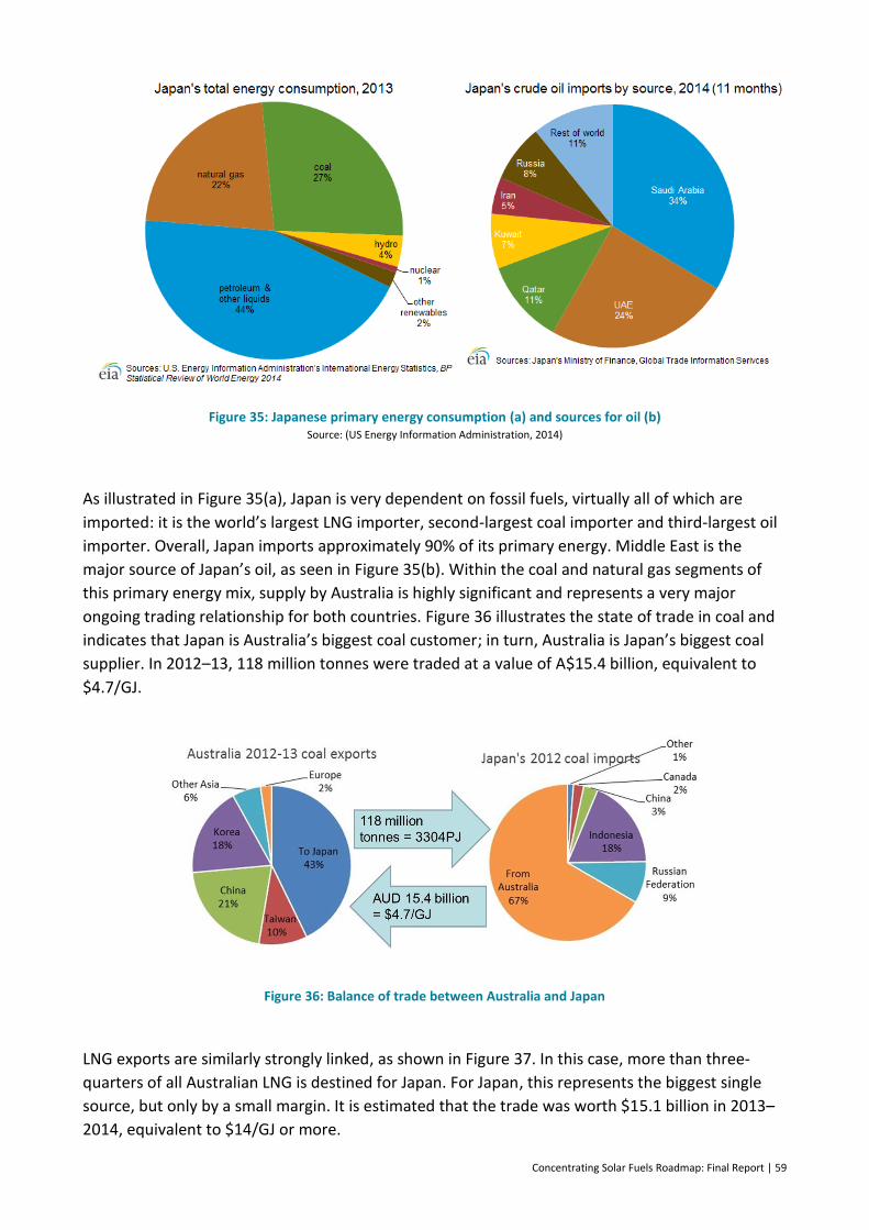
Concentrating Solar Fuels Roadmap: Final Report | 59
Figure 35: Japanese primary energy consumption (a) and sources for oil (b) Source: (US Energy Information Administration, 2014)
As illustrated in Figure 35(a), Japan is very dependent on fossil fuels, virtually all of which are
imported: it is the world’s largest LNG importer, second-largest coal importer and third-largest oil
importer. Overall, Japan imports approximately 90% of its primary energy. Middle East is the
major source of Japan’s oil, as seen in Figure 35(b). Within the coal and natural gas segments of
this primary energy mix, supply by Australia is highly significant and represents a very major
ongoing trading relationship for both countries. Figure 36 illustrates the state of trade in coal and
indicates that Japan is Australia’s biggest coal customer; in turn, Australia is Japan’s biggest coal
supplier. In 2012–13, 118 million tonnes were traded at a value of A$15.4 billion, equivalent to
$4.7/GJ.
Figure 36: Balance of trade between Australia and Japan
LNG exports are similarly strongly linked, as shown in Figure 37. In this case, more than three-
quarters of all Australian LNG is destined for Japan. For Japan, this represents the biggest single
source, but only by a small margin. It is estimated that the trade was worth $15.1 billion in 2013–
2014, equivalent to $14/GJ or more.
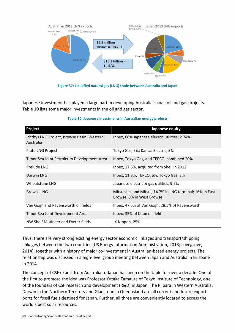
60 | Concentrating Solar Fuels Roadmap: Final Report
Figure 37: Liquefied natural gas (LNG) trade between Australia and Japan
Japanese investment has played a large part in developing Australia’s coal, oil and gas projects.
Table 10 lists some major investments in the oil and gas sector.
Table 10: Japanese investments in Australian energy projects
Project Japanese equity
Ichthys LNG Project, Browse Basin, Western Australia
Inpex, 66% Japanese electric utilities: 2.74%
Pluto LNG Project Tokyo Gas, 5%; Kansai Electric, 5%
Timor Sea Joint Petroleum Development Area Inpex, Tokyo Gas, and TEPCO, combined 20%
Prelude LNG Inpex, 17.5%, acquired from Shell in 2012
Darwin LNG Inpex, 11.3%; TEPCO, 6%; Tokyo Gas, 3%
Wheatstone LNG Japanese electric & gas utilities, 9.5%
Browse LNG Mitsubishi and Mitsui, 14.7% in LNG terminal; 16% in East Browse; 8% in West Browse
Van Gogh and Ravensworth oil fields Inpex, 47.5% of Van Gogh; 28.5% of Ravensworth
Timor Sea Joint Development Area Inpex, 35% of Kitan oil field
NW Shelf Mutineer and Exeter fields JX Nippon, 25%
Thus, there are very strong existing energy sector economic linkages and transport/shipping
linkages between the two countries (US Energy Information Administration, 2013; Lovegrove,
2014), together with a history of major co-investment in Australian-based energy projects. The
relationship was discussed in a high-level group meeting between Japan and Australia in Brisbane
in 2014.
The concept of CSF export from Australia to Japan has been on the table for over a decade. One of
the first to promote the idea was Professor Yutaka Tamaura of Tokyo Institute of Technology, one
of the founders of CSF research and development (R&D) in Japan. The Pilbara in Western Australia,
Darwin in the Northern Territory and Gladstone in Queensland are all current and future export
ports for fossil fuels destined for Japan. Further, all three are conveniently located to access the
world’s best solar resources.
Concentrating Solar Fuels Roadmap: Final Report | 61
Japan recently developed a strategic vision for energy supply and distribution (Government of
Japan, 2014). This rests on three pillars: energy security, economic efficiency and environment.
Energy security is seen as the biggest problem facing Japan. As stated above, it relies heavily on
imported fossil fuels, which has only increased since the Fukushima nuclear accident in 2010. In
particular, Japan’s reliance on the Middle East for 83% of its oil is seen as the largest security
problem. Japan sees diversification of its energy supply (or ‘multilayered’ energy supply) as key to
increasing energy security, which may mean returning to nuclear energy. However, it also provides
an opportunity for alternatives to Middle Eastern oil for transport to enter the market.
Another solution envisaged for increasing energy security, particularly in disaster situations, is to
promote the use of distributed generation, such as fuel cells and photovoltaics; battery storage
and smart grids. The use of methane hydrates, which are located in the oceans surrounding Japan,
is seen as an opportunity for secure, domestic supply, even with the potentially high GHG
emissions associated with this resource.
Improving economic efficiency is the second pillar of Japan’s energy vision. Since the Fukushima
disaster and the increasing reliance on LNG, Japan’s trade deficit has increased to a record high of
11.5 trillion yen. In addition, because of the high cost of LNG, electricity prices in Japan are six
times higher than in the United States. The concern is that industry will relocate from Japan to
regions with lower-cost energy, making Japan’s economic situation worse. Therefore, energy
efficiency and the use of cheaper forms of energy are being promoted.
Removing energy sectoral barriers and increasing competition is also seen as an advantage. One of
the cheaper forms of energy is coal, which Japan currently imports from Australia. Japan is
promoting the development of efficient, integrated gasification combined-cycle coal technologies
in its bid to continue domestic coal use. It is also examining projects in Australia that are
converting low-cost brown coal to transport fuel for use in Japan (Lovegrove, 2014).
The third pillar of Japan’s energy vision is the environment. The country remains committed to
reducing its GHG emissions. It sees cleaner, advanced coal technologies as a key route to this,
together with major initiatives in renewable energy. The main policy for the development of
renewable energy in Japan is a feed-in tariff. Other measures include batteries and hydrogen as
storage for smoothing wind and solar output, and assistance with development proposals. Japan is
also actively promoting the use of hydrogen.
The Japanese Ministry of Economy, Trade and Industry (METI), in collaboration with industry and
other government bodies, produced a roadmap for the uptake of hydrogen in Japan (Tobe, 2014).
Japan is interested in pursuing hydrogen for several reasons (IEA, 2012b):
– Japan currently holds the majority of fuel cell patents, thus a push for hydrogen use in fuel
cells (fuel cell vehicles in particular) will result in greater use of Japanese technology
globally and improve Japan’s economy. By 2025, the IEA estimates that the fuel cell
market will be worth five trillion yen, and that Europe, the United States and South Korea
will have hydrogen and fuel cell programs.
– The use of hydrogen diversifies energy resources and therefore increases energy security.
It can be produced from both fossil fuels and renewable resources, and thus may be
produced locally, reducing reliance on imported oil in particular. Hydrogen in distributed

62 | Concentrating Solar Fuels Roadmap: Final Report
fuel cells (i.e. in EVs) can also be used to supply local electricity in energy supply
disruptions/blackouts.
– Depending on the method of production, hydrogen has zero CO2 emissions at the point of
use and potentially zero emissions overall.
To reach Japan’s goal of at least 6000 hydrogen fuel cell vehicles on the road by 2020, hydrogen
refuelling stations are being set up around the country, the costs of which are subsidised by up to
one-third through a joint agreement between automakers (autoblog, 2015). It is envisaged that
hydrogen will be produced centrally and distributed to the refuelling stations, and that hydrogen
will be imported into Japan as well as being produced locally (Tobe, 2014).
Japan has also promoted the idea of burning hydrogen directly in gas turbines, instead of using
natural gas. Using hydrogen is more efficient and will have zero emissions. The largest future
source of demand for hydrogen in Japan may result from this use (Hinkley et al., 2015a).
Due to limited land availability and the desire to reduce GHG emissions, Japan will need to
supplement its own domestic supply of hydrogen with imported hydrogen. Various means of
transporting the fuel into Japan are under examination. A US$20 million ‘New Energy (hydrogen)
carrier project’ was commenced as a joint effort by the Ministry of Education, Culture Sports,
Science and Technology and METI in April 2013. Various hydrogen transport approaches are being
considered. Chiyoda Corporation is promoting a hydrogen transport system based on the
reversible hydrogenation of toluene. Kawasaki Heavy Industries favour the use of cryogenic liquid
hydrogen for international transport. They are currently engaged in a detailed study for a project
that intends to gasify brown coal from Victoria’s Latrobe Valley: converting all CO to CO2 to
maximise H2 production, sequestering the CO2 as part of the Carbon Net project, and then
liquefying the hydrogen for export in purpose-built ships. A system capable of 770 t/day of
hydrogen production is targeted (Figure 38).
Figure 38: Kawasaki Heavy Industries’ vision for the cryogenic liquid hydrogen market

Concentrating Solar Fuels Roadmap: Final Report | 63
The infrastructure needed for transport and storage of liquid hydrogen is conceptually similar to
that used for LNG. Australia currently exports LNG to Asia from the North West Shelf, Darwin and
Gladstone. However, the temperatures needed for hydrogen liquefaction are considerably lower
and harder to achieve than for LNG.
There may be an opportunity for hydrogen production using solar brown coal gasification,
although the DNI in the Latrobe Valley is relatively low, and other deposits in South Australia may
be more favourable (Lovegrove, 2014; Kodama, 2013).
A third alternative is to use the Haber–Bosch process to synthesise ammonia from hydrogen and
transport ammonia liquid. A large ammonia production facility in the Pilbara, Western Australia,
already exports liquid ammonia around the world, including to Japan. Mitsubishi Corporation, a
major ammonia customer/trader, is understood to have an interest in this approach to hydrogen
trade. As discussed in Section 2.8.5, current conventional ammonia production uses steam
reforming of natural gas to provide the input hydrogen for the Haber–Bosch process. This offers
an immediate opening for solar-driven natural gas reforming as a route to a CSF hybrid that could
address the Japanese hydrogen market.
3.5.2 China
The China Australia Free Trade Agreement (ChAFTA) that came into force on 20 December 2015
Australia and China should increase the level of trade between the two countries. Although China
is the world’s largest energy consumer, it meets much of its own energy needs. Relevant statistics
comparing Australia and China are given in Table 11.
Table 11: Comparison of Chinese and Australian parameters relevant to the concentrating solar fuel (CSF) trade
Parameter China Australia
Population 1,357 million 22 million
Electricity installed capacity 1,174 GW 49 GW
Land area 9.6 million sq. km 7.7 million sq. km
Primary energy consumption 111,711 PJ/a 5,800 PJ/a
Direct normal irradiance Extremely variable: 730–
3285 kWh/m2/year (7.2–
32.4 MJ/m2/day)
~2300 kWh/m2 /year (22.7
MJ/m2/day)
Net energy flow Importer Exporter
Figure 39 breaks down Chinese primary energy consumption by fuel type and crude oil import
sources. The majority of China’s energy comes from coal, which was entirely sourced from within
China until 2009, when demand outstripped supply and it began to be imported. Sixty-five per

64 | Concentrating Solar Fuels Roadmap: Final Report
cent of this imported coal came from Australia and Indonesia. Coal consumption peaked in 2013
and declined by 11% in 2014 to 290 million tonnes. China aims to reduce coal consumption to 62%
of primary energy supply by 2020.
Figure 39: China’s primary energy consumption and source of crude oil imports Source: (US Energy Information Administration, 2014)
China is the world’s largest oil consumer, and even though it has its own oil fields and refineries, it
is the world’s largest oil importer. It currently produces 4.6 million bbl/day of petroleum and other
liquids, and imports 6.1 million bbl/day. Diesel is the most consumed petroleum product, at 34%
of demand, followed by gasoline at 23%. The diesel share is expected to decrease and the gasoline
share to increase in the future, due to improved truck fuel efficiencies and newer fleets, decreased
production from mining and an increase in demand for passenger vehicles.
China has aimed to diversify its oil import sources to increase fuel security. It also aims to build
significant oil storage capacity as a buffer against oil supply disruptions.
Natural gas is only responsible for 5% of China’s primary energy consumption, but the size of this
consumption makes China the world’s third-largest LNG importer (behind Japan and South Korea),
even though it produces ~74% (4.452 exajoules (EJ)/year) of its natural gas domestically and
imports gas through pipelines. Australia is the second-largest source of LNG for China, at 19%,
behind Qatar at 34% (Figure 40).
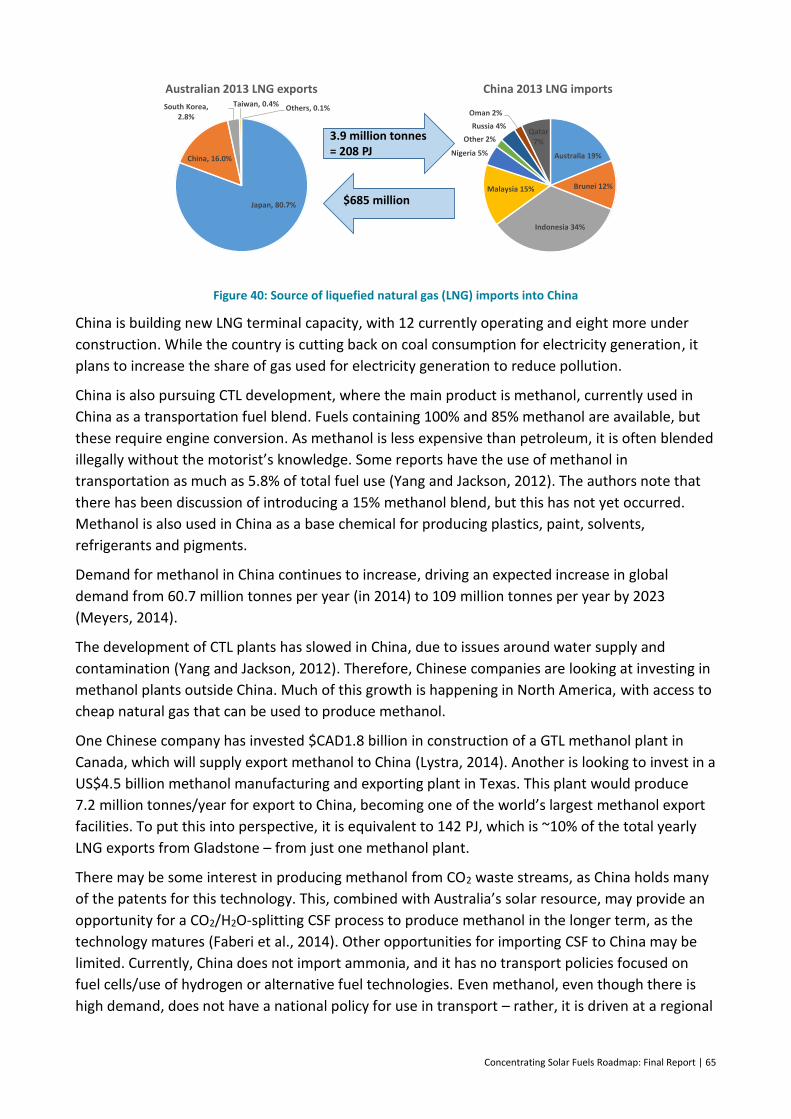
Concentrating Solar Fuels Roadmap: Final Report | 65
Figure 40: Source of liquefied natural gas (LNG) imports into China
China is building new LNG terminal capacity, with 12 currently operating and eight more under
construction. While the country is cutting back on coal consumption for electricity generation, it
plans to increase the share of gas used for electricity generation to reduce pollution.
China is also pursuing CTL development, where the main product is methanol, currently used in
China as a transportation fuel blend. Fuels containing 100% and 85% methanol are available, but
these require engine conversion. As methanol is less expensive than petroleum, it is often blended
illegally without the motorist’s knowledge. Some reports have the use of methanol in
transportation as much as 5.8% of total fuel use (Yang and Jackson, 2012). The authors note that
there has been discussion of introducing a 15% methanol blend, but this has not yet occurred.
Methanol is also used in China as a base chemical for producing plastics, paint, solvents,
refrigerants and pigments.
Demand for methanol in China continues to increase, driving an expected increase in global
demand from 60.7 million tonnes per year (in 2014) to 109 million tonnes per year by 2023
(Meyers, 2014).
The development of CTL plants has slowed in China, due to issues around water supply and
contamination (Yang and Jackson, 2012). Therefore, Chinese companies are looking at investing in
methanol plants outside China. Much of this growth is happening in North America, with access to
cheap natural gas that can be used to produce methanol.
One Chinese company has invested $CAD1.8 billion in construction of a GTL methanol plant in
Canada, which will supply export methanol to China (Lystra, 2014). Another is looking to invest in a
US$4.5 billion methanol manufacturing and exporting plant in Texas. This plant would produce
7.2 million tonnes/year for export to China, becoming one of the world’s largest methanol export
facilities. To put this into perspective, it is equivalent to 142 PJ, which is ~10% of the total yearly
LNG exports from Gladstone – from just one methanol plant.
There may be some interest in producing methanol from CO2 waste streams, as China holds many
of the patents for this technology. This, combined with Australia’s solar resource, may provide an
opportunity for a CO2/H2O-splitting CSF process to produce methanol in the longer term, as the
technology matures (Faberi et al., 2014). Other opportunities for importing CSF to China may be
limited. Currently, China does not import ammonia, and it has no transport policies focused on
fuel cells/use of hydrogen or alternative fuel technologies. Even methanol, even though there is
high demand, does not have a national policy for use in transport – rather, it is driven at a regional
Japan, 80.7%
China, 16.0%
South Korea, 2.8%
Taiwan, 0.4% Others, 0.1%
Australian 2013 LNG exports
Australia 19%
Brunei 12%
Indonesia 34%
Malaysia 15%
Nigeria 5%
Other 2%
Russia 4%
Oman 2%
Qatar7%
China 2013 LNG imports
3.9 million tonnes = 208 PJ
$685 million
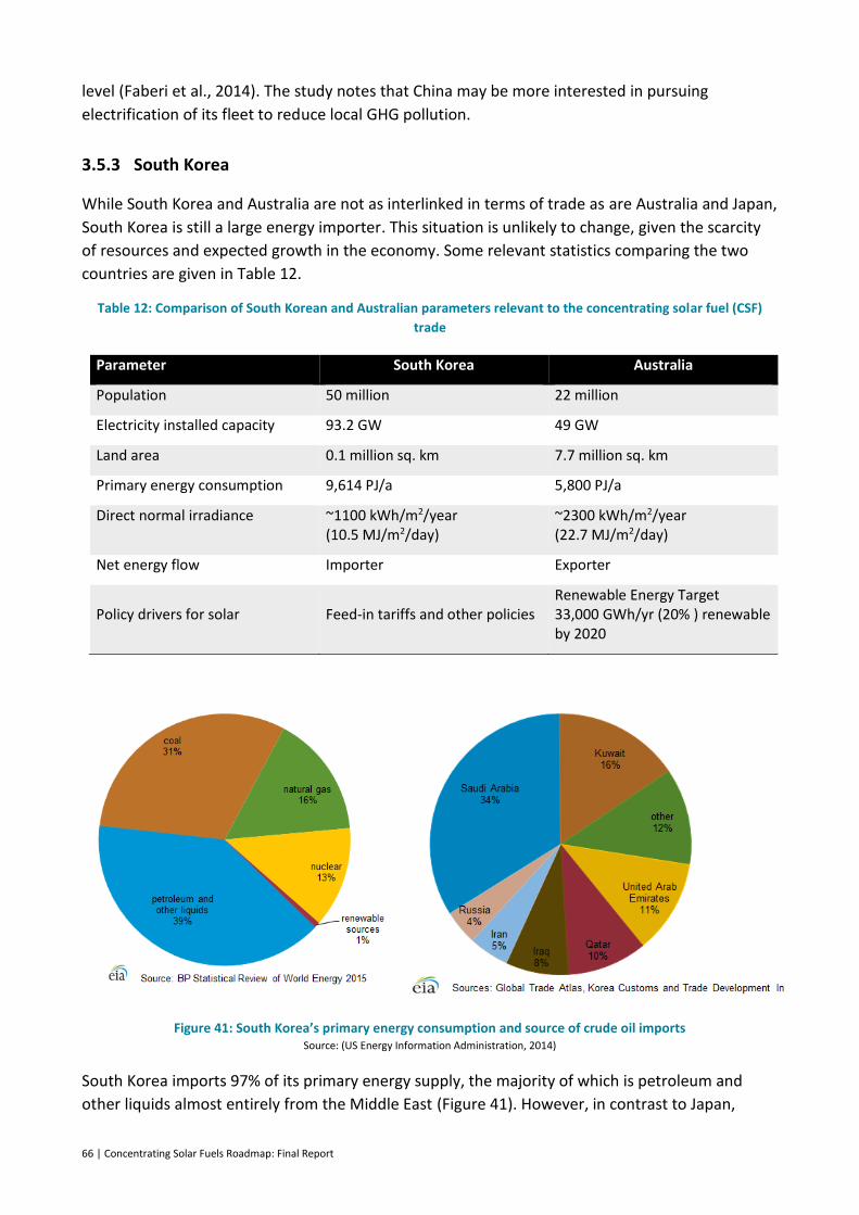
66 | Concentrating Solar Fuels Roadmap: Final Report
level (Faberi et al., 2014). The study notes that China may be more interested in pursuing
electrification of its fleet to reduce local GHG pollution.
3.5.3 South Korea
While South Korea and Australia are not as interlinked in terms of trade as are Australia and Japan,
South Korea is still a large energy importer. This situation is unlikely to change, given the scarcity
of resources and expected growth in the economy. Some relevant statistics comparing the two
countries are given in Table 12.
Table 12: Comparison of South Korean and Australian parameters relevant to the concentrating solar fuel (CSF)
trade
Parameter South Korea Australia
Population 50 million 22 million
Electricity installed capacity 93.2 GW 49 GW
Land area 0.1 million sq. km 7.7 million sq. km
Primary energy consumption 9,614 PJ/a 5,800 PJ/a
Direct normal irradiance ~1100 kWh/m2/year (10.5 MJ/m2/day)
~2300 kWh/m2/year (22.7 MJ/m2/day)
Net energy flow Importer Exporter
Policy drivers for solar Feed-in tariffs and other policies Renewable Energy Target 33,000 GWh/yr (20% ) renewable by 2020
Figure 41: South Korea’s primary energy consumption and source of crude oil imports Source: (US Energy Information Administration, 2014)
South Korea imports 97% of its primary energy supply, the majority of which is petroleum and
other liquids almost entirely from the Middle East (Figure 41). However, in contrast to Japan,

Concentrating Solar Fuels Roadmap: Final Report | 67
South Korea is one of Asia’s largest exporters of refined oil products: mainly middle distillates,
such as gas oil and jet fuel. It has three of the world’s largest top ten oil refineries, with a total
capacity of almost 3 million bbl/day. And, because of the lack of a domestic crude oil supply, South
Korean oil companies invest heavily in overseas exploration and production.
Figure 42: Source of liquefied natural gas (LNG) imports into South Korea (US Energy Information Administration, 2014)
South Korea is the world’s second-largest importer of LNG, with consumption expected to grow by
1.7% per year, mainly for electricity generation, to reduce GHG emissions in line with the country’s
long-term energy plan. Despite its large reliance on LNG, it only receives 2% of its supply from
Australia (Figure 42), but recently signed three major LNG contracts to secure supply from here.
Once full production is complete, South Korea is expected receive 25% of its LNG supply from
Australia, which should make Australia one of its major suppliers (Department of Foreign Affairs
and Trade, 2014).
The situation for coal is quite different from that of LNG. Australia is the largest supplier of coal to
South Korea (Figure 43), exporting an estimated 16.4 Mt of coking and 28.3 Mt of steam coal in
2011 (IEA, 2012a). In South Korea, 62% of the coal supply is used to generate electricity, with the
remainder used in the industrial sector.
Figure 43: Balance of trade in coal between Australia and South Korea
45 million tonnes = 1252 PJ
AUD 7 billion = ~5.6 $/GJ
68 | Concentrating Solar Fuels Roadmap: Final Report
As can be seen from the above statistics, Australia has a strong energy trade relationship with
South Korea, which is expected to grow rapidly in the near future. The prospect of increasing LNG
exports to South Korea also opens up avenues for the export of other forms of energy.
Since 2009, South Korea has had a suite of strategies aimed at reducing emissions based on its
‘Low Carbon Green Growth’ policy (Ministry of Government Registration, 2010). This policy
includes various incentives to encourage the use of renewable energy and increases energy
efficiency, with the specific aims of:
– fighting climate change and other environmental threats
– creating a synergistic relationship between gross domestic product and environmental
protection
– increasing energy security by reducing dependence on imported fossil fuels
– developing new green industries for the future
– improving quality of life and increasing South Korea’s international standing.
The policies are mainly aimed at reducing emissions from electricity generation, such as renewable
portfolio standards, a solar roofs program and reducing energy use in new buildings through
better design and energy efficiency. An emissions trading scheme will be introduced in 2015, with
the aim of reducing emissions by 30% by 2020 (IEA, 2012a).
Although South Korea is promoting the use of public transport, their renewable portfolio
standards encourage the use of fuel cells in the home and in vehicles, with tax breaks, subsidies
and low-interest loans available to assist with uptake. In February 2014, a 59-MW fuel cell park
was commissioned as part of the Gyeonggi Green Energy Facility. The fuel cells use hydrogen
(produced from methane) and provide power and district heating (Overton, 2014). There are plans
to build more of these types of facilities around Seoul, as the capital also has its own emissions
reduction targets of reducing GHG emissions by 25% by 2020, and 40% by 2030, from 1990 levels
(City Climate Leadership Awards, 2014).
Hyundai has been producing fuel cell vehicles since 2013 and plans to increase production, with a
roll out of hydrogen refuelling infrastructure in South Korea, as well as pursuing opportunities in
Europe and California (Shul, 2012; Szondy, 2014). As with Japan, there may be opportunities to
export hydrogen produced using low-emission technologies to South Korea in the longer term.
3.6 Summary
The prices of energy commodities have always been volatile and will continue to be so. However,
it is certain that the majority of commodities are linked to the oil price. We have therefore been
able to project future commodity prices for CSF for export to Asia and domestic use in Australia by
using future oil and LNG price trajectories as a basis.
The use of the fuel determines its price in the market. For example, DME may be produced from
methanol, but its price (on an energy basis) is lower, because its main use is as a propane
alternative in China. For this reason, this fuel is excluded from further financial analysis in this
study.

Concentrating Solar Fuels Roadmap: Final Report | 69
On the other hand, exporting hydrogen to Japan and South Korea – whether as ammonia or liquid
hydrogen – looks to be a promising opportunity for CSF. Japan and South Korea are pursuing fuel
cell technologies, and are thus looking for sources of hydrogen. Japanese companies have already
drawn up plans to convert Victorian brown coal into hydrogen to export to Japan. Adding solar
energy to this process would significantly reduce GHG emissions. Current opportunities are also
available for exporting methanol to China, given that the country is developing large methanol
production facilities in North America, and has now signed a free trade agreement with Australia.
Locally, diesel as a CSF represents a strong opportunity. This is due to high demand, widely-
distributed use in remote regions in particular, and the fact that modelling shows that synfuel
diesel alternatives are projected to be used by 2025. Blending of methanol with gasoline is
another initial market that does not require infrastructure or vehicle changes. Addition of a
modest fraction of solar derived hydrogen in the natural gas pipeline network would also be a
means of contributing to non-transport energy use.
Developing a CSF industry in Australia would also help regional development, particularly if
biomass is used as a feedstock. Biomass feedstocks would also produce a zero-emission fuel.
Within Australia, our reliance on imported oil has raised both energy security and economic
concerns. Domestic CSF production would help to reduce our dependence on foreign oil. Australia
has ample solar, coal and biomass resources to produce pure and/or hybrid CSF. The relative sale
prices of (and demand for) fuels that can be produced using high-temperature solar energy – such
as hydrogen, synthetic drop-in fuels or methanol – will determine which CSF technologies are
most likely to become commercial.
70 | Concentrating Solar Fuels Roadmap: Final Report
4 Techno-economic analysis of options
As outlined in Section 3, there is a significant opportunity for concentrating solar fuels (CSF), as
long as they are economic. This section focuses on the techno-economic assessment of the large
number of different CSF technologies considered in this study. The levelised cost of fuel (LCOF) for
the most prospective technologies is presented at the end of this section. The aim of the techno-
economic analysis was to compare the possible options across a range of metrics including the
LCOF. This comparison leads to rankings either by cost or by a weighted combination of the
individual metrics. The intention with this approach is to provide direction to priority areas for
effort and investment. It also provides a mechanism, for a particular option, to consider its
apparent competitiveness and provide indications on how that might be improved. It is important
to point out however, that the selected options are an approximate categorisation of an enormous
range of possibilities and so the ranking should not be over interpreted. It is also the case that a
new invention or improvement could completely change the future ranking of these options.
4.1 Technical screening assessment
As part of this project, the project team performed a detailed technical assessment of the state-of-
the-art for various solar technologies and research efforts in the area of CSF (Hinkley et al., 2013).
This has been updated and forms the technical appendix of this study (Appendix A.1). Various key
solar technical parameters (e.g. temperatures of reactions, exit conversions, recuperation
efficiency) were estimated using consensus values agreed among the authors. The estimates were
informed by knowledge of reported experimental results to date, as well as the approximate ideal
limits. The values used are intended to be best estimates of ‘realistic/optimistic’ values that would
be encountered during the early years of commercial operation. They have been examined for
accuracy as part of the stakeholder assessment (Section 4.3).
Besides using the material in Appendix A.1 to determine values of technical parameters, for input
to performance and economic analysis, it has also been used to inform an evaluation of qualitative
technical metrics on a consistent basis. The combination of receivers and reactions described in
Section 2 results in a possible 160 permutations. As a primary method of screening, the expert
panel eliminated any combinations of reactor/receiver/chemistry that are technically impossible.
For example rotating recuperating reactors are a concept developed specifically for non-volatile
metal oxide redox processes and so are not considered for volatile metal oxides or gasification
systems with an inflow of solid reactants. This process eliminated 75 combinations, leaving 85 for
further assessment.
The qualitative technical selection criteria used and the reasons for choosing them were:
Greenhouse gas intensity: it is clearly important to reduce GHG emissions from fuel use. In the
absence of a particular price on CO2 as an input to cost of energy calculations, the CO2
intensity of final combustion products was used as a screening metric, and a scale factor was
incorporated to allow a distinction between carbon of biomass or fossil origin.
Concentrating Solar Fuels Roadmap: Final Report | 71
Technology readiness level: the TRL scale (see Appendix A.2) is a commonly-used engineering
metric to assess the technical maturity of a technology. Technologies that have a higher TRL
are more mature and thus more likely to become commercial before those with a lower TRL.
Current Level of R&D effort: if an area has a great deal of research and development (R&D)
activity, a breakthrough is more likely, and thus the technologies move up the TRL scale faster.
Therefore, identifying the current level of R&D activity helps to determine the future maturity
of the technology, or opportunities where increased investment could make a large difference.
Difficulty of unsolved hurdles: the project team worked with the expert panel to identify and
evaluate the technical hurdle(s) that need to be overcome. Solutions to these issues would
greatly improve the maturity and efficiency of the technology while reducing costs.
The summary tables from the qualitative screening analysis are presented in Appendix A.4.
4.2 Economic assessment
The most appropriate economic performance metric for a solar fuels system is the Levelised cost
of Fuel (Energy) (LCOF / E). This is a cost per unit of fuel produced that represents break-even
operation by amortisation of capital investment over the project lifetime using the appropriate
discount rate, plus O&M costs and the cost of any inputs.
In this study, we used a two-part economic assessment. The first is an assessment of the LCOE of
solar product gas (syngas) production from each of the many different solar options considered.
Taking the most prospective solar options from the technical assessment, the second economic
assessment calculates the LCOF of different CSF from various fuel conversion technologies
identified in Section 2.
The method used is detailed in more detail in Appendix A.3. Key financial parameters used
included a weighted average cost of capital 6.4% and a 30 year plant life, consistent with
assumptions in the recent Australian power generation technology report (CO2CRC, 2015).
Analysis began with a solar field calculation that assumed a fixed thermal input to the receiver for
all CSF options and worked backwards to determine a solar field size based on a receiver efficiency
calculation with operating temperature as a key input. Plant capital costs were estimated using
cost parameters by plant area or component (e.g. tower, receiver). Time based cost de-escalation
allowed construction in different future years to be evaluated.
The capital cost of receiver units is important. For this purpose the specific cost of a molten salt
receiver from previous studies of CSP systems was taken as a baseline. Part of the technical
assessment involved the expert panel separately using qualitative judgement to estimate a
receiver complexity scale factor to be applied to this baseline for each basic receiver approach.
The views of the experts were average. Thus a tubular directly irradiated receiver was considered
to be approximately equal cost to a molten salt receiver, whereas a more complex rotating
recuperating reactor for redox processes was judged to be 2.5 times more expensive.
A major determinant of syngas LCOE and the main source of relative differentiation between the
options is the solar to chemical conversion efficiency. While many of the references cited in
Appendix A.1 attempt to estimate this for particular reaction systems, they typically use different
72 | Concentrating Solar Fuels Roadmap: Final Report
assumptions and are difficult to compare. As part of this project a comprehensive first principles
analysis has been used to attempt to compare the options on a consistent basis.
The major determining mechanism is that in each case reactants and other mass flows must be
heated to the operating temperature of the reaction, reacted and then products and inert masses
must be cooled back to ambient conditions. Recovery of heat between cooled products and
heating of reactants is key to improving solar to chemical conversion efficiency, but it is always
imperfect. High operating temperatures, incomplete conversion of reactants and presence of
amounts of inert material all work to lower solar to chemical conversion efficiency.
Thus the analysis as detailed in Appendix A.3 carries out a complete energy balance analysis of an
arbitrary process using mass flows, completeness of reaction, presence of excess reactants,
presence of cycled inert materials and efficiency of recuperation as inputs. These more basic input
parameters were estimated on an ‘optimistic/realistic’ basis by consensus of the panel of experts.
The results gave efficiencies of conversion of thermal energy at the receiver to stored chemical
energy that ranged from around 30% to 70%, a major differentiating factor. Receiver thermal
efficiency in addition to this, was determined from a simple thermal loss model based on
operating temperature.
Building on the results for the solar product gas LCOE, a further calculation was carried out to
determine the LCOF of end use fuels. For this purpose the LCOE of the solar product gas for each
option was used as an input energy stream to a process that then counted the capital costs of gas
storage and the synthesis plant, considering also the estimated efficiencies and other parameters.
Options considered were:
Diesel production from a Fischer Tropsch based plant
Methanol production
Ammonia synthesis using the Haber Bosch process.
To assess the future opportunities of these overall CSF technologies, the future capital costs need
to be determined. For any technology, future cost reductions besides those due to economies of
scale could be achieved through technological learning effects or ‘learning-by-doing’ in the
components that are immature.
Learning-by-doing describes the relationship between cost reductions and cumulative output or
capacity that has been observed in industrial processes, where for every doubling in cumulative
output, the cost of production reduces by a fixed percentage known as the learning rate (LR)
(Ferioli et al., 2009; Grübler et al., 1999). This relationship is represented by the learning curve
equation:
where K is the capital cost of the technology, K0 is the capital cost of first unit or initial cumulative
capacity of the technology, CC is the cumulative number of units or cumulative capacity, b is the
learning index, related to the LR by , where LR is expressed as a percentage.
However, according to the equation, determining potential future cost reductions requires the
future uptake of the technology over time to be estimated.
0
bK K CC
100 1 2bLR
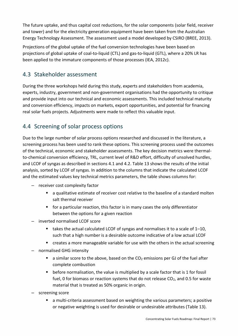
Concentrating Solar Fuels Roadmap: Final Report | 73
The future uptake, and thus capital cost reductions, for the solar components (solar field, receiver
and tower) and for the electricity generation equipment have been taken from the Australian
Energy Technology Assessment. The assessment used a model developed by CSIRO (BREE, 2013).
Projections of the global uptake of the fuel conversion technologies have been based on
projections of global uptake of coal-to-liquid (CTL) and gas-to-liquid (GTL), where a 20% LR has
been applied to the immature components of those processes (IEA, 2012c).
4.3 Stakeholder assessment
During the three workshops held during this study, experts and stakeholders from academia,
experts, industry, government and non-government organisations had the opportunity to critique
and provide input into our technical and economic assessments. This included technical maturity
and conversion efficiency, impacts on markets, export opportunities, and potential for financing
real solar fuels projects. Adjustments were made to reflect this valuable input.
4.4 Screening of solar process options
Due to the large number of solar process options researched and discussed in the literature, a
screening process has been used to rank these options. This screening process used the outcomes
of the technical, economic and stakeholder assessments. The key decision metrics were thermal-
to-chemical conversion efficiency, TRL, current level of R&D effort, difficulty of unsolved hurdles,
and LCOF of syngas as described in sections 4.1 and 4.2. Table 13 shows the results of the initial
analysis, sorted by LCOF of syngas. In addition to the columns that indicate the calculated LCOF
and the estimated values key technical metrics parameters, the table shows columns for:
– receiver cost complexity factor
a qualitative estimate of receiver cost relative to the baseline of a standard molten
salt thermal receiver
for a particular reaction, this factor is in many cases the only differentiator
between the options for a given reaction
– inverted normalised LCOF score
takes the actual calculated LCOF of syngas and normalises it to a scale of 1–10,
such that a high number is a desirable outcome indicative of a low actual LCOF
creates a more manageable variable for use with the others in the actual screening
– normalised GHG intensity
a similar score to the above, based on the CO2 emissions per GJ of the fuel after
complete combustion
before normalisation, the value is multiplied by a scale factor that is 1 for fossil
fuel, 0 for biomass or reaction systems that do not release CO2, and 0.5 for waste
material that is treated as 50% organic in origin.
– screening score
a multi-criteria assessment based on weighting the various parameters; a positive
or negative weighting is used for desirable or undesirable attributes (Table 13).
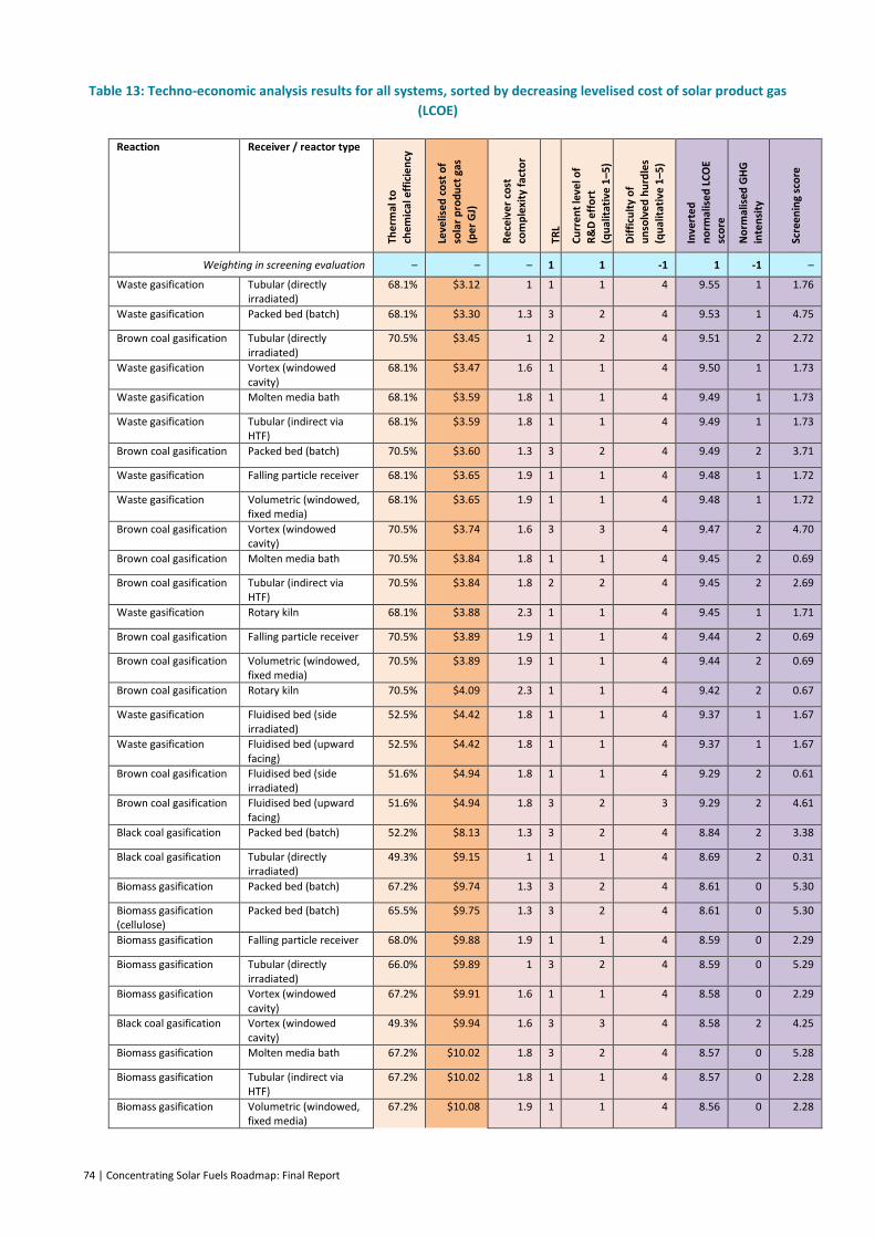
74 | Concentrating Solar Fuels Roadmap: Final Report
Table 13: Techno-economic analysis results for all systems, sorted by decreasing levelised cost of solar product gas
(LCOE)
Reaction Receiver / reactor type
The
rmal
to
chem
ical
eff
icie
ncy
Leve
lise
d c
ost
of
sola
r p
rod
uct
gas
(p
er
GJ)
Re
ceiv
er
cost
co
mp
lexi
ty f
acto
r
TRL
Cu
rre
nt
leve
l of
R&
D e
ffo
rt
(qu
alit
ativ
e 1
–5)
Dif
ficu
lty
of
un
solv
ed
hu
rdle
s
(qu
alit
ativ
e 1
–5)
Inve
rte
d
no
rmal
ise
d L
CO
E sc
ore
No
rmal
ised
GH
G
inte
nsi
ty
Scre
en
ing
sco
re
Weighting in screening evaluation – – – 1 1 -1 1 -1 –
Waste gasification Tubular (directly irradiated)
68.1% $3.12 1 1 1 4 9.55 1 1.76
Waste gasification Packed bed (batch) 68.1% $3.30 1.3 3 2 4 9.53 1 4.75
Brown coal gasification Tubular (directly irradiated)
70.5% $3.45 1 2 2 4 9.51 2 2.72
Waste gasification Vortex (windowed cavity)
68.1% $3.47 1.6 1 1 4 9.50 1 1.73
Waste gasification Molten media bath 68.1% $3.59 1.8 1 1 4 9.49 1 1.73
Waste gasification Tubular (indirect via HTF)
68.1% $3.59 1.8 1 1 4 9.49 1 1.73
Brown coal gasification Packed bed (batch) 70.5% $3.60 1.3 3 2 4 9.49 2 3.71
Waste gasification Falling particle receiver 68.1% $3.65 1.9 1 1 4 9.48 1 1.72
Waste gasification Volumetric (windowed, fixed media)
68.1% $3.65 1.9 1 1 4 9.48 1 1.72
Brown coal gasification Vortex (windowed cavity)
70.5% $3.74 1.6 3 3 4 9.47 2 4.70
Brown coal gasification Molten media bath 70.5% $3.84 1.8 1 1 4 9.45 2 0.69
Brown coal gasification Tubular (indirect via HTF)
70.5% $3.84 1.8 2 2 4 9.45 2 2.69
Waste gasification Rotary kiln 68.1% $3.88 2.3 1 1 4 9.45 1 1.71
Brown coal gasification Falling particle receiver 70.5% $3.89 1.9 1 1 4 9.44 2 0.69
Brown coal gasification Volumetric (windowed, fixed media)
70.5% $3.89 1.9 1 1 4 9.44 2 0.69
Brown coal gasification Rotary kiln 70.5% $4.09 2.3 1 1 4 9.42 2 0.67
Waste gasification Fluidised bed (side irradiated)
52.5% $4.42 1.8 1 1 4 9.37 1 1.67
Waste gasification Fluidised bed (upward facing)
52.5% $4.42 1.8 1 1 4 9.37 1 1.67
Brown coal gasification Fluidised bed (side irradiated)
51.6% $4.94 1.8 1 1 4 9.29 2 0.61
Brown coal gasification Fluidised bed (upward facing)
51.6% $4.94 1.8 3 2 3 9.29 2 4.61
Black coal gasification Packed bed (batch) 52.2% $8.13 1.3 3 2 4 8.84 2 3.38
Black coal gasification Tubular (directly irradiated)
49.3% $9.15 1 1 1 4 8.69 2 0.31
Biomass gasification Packed bed (batch) 67.2% $9.74 1.3 3 2 4 8.61 0 5.30
Biomass gasification (cellulose)
Packed bed (batch) 65.5% $9.75 1.3 3 2 4 8.61 0 5.30
Biomass gasification Falling particle receiver 68.0% $9.88 1.9 1 1 4 8.59 0 2.29
Biomass gasification Tubular (directly irradiated)
66.0% $9.89 1 3 2 4 8.59 0 5.29
Biomass gasification Vortex (windowed cavity)
67.2% $9.91 1.6 1 1 4 8.58 0 2.29
Black coal gasification Vortex (windowed cavity)
49.3% $9.94 1.6 3 3 4 8.58 2 4.25
Biomass gasification Molten media bath 67.2% $10.02 1.8 3 2 4 8.57 0 5.28
Biomass gasification Tubular (indirect via HTF)
67.2% $10.02 1.8 1 1 4 8.57 0 2.28
Biomass gasification Volumetric (windowed, fixed media)
67.2% $10.08 1.9 1 1 4 8.56 0 2.28
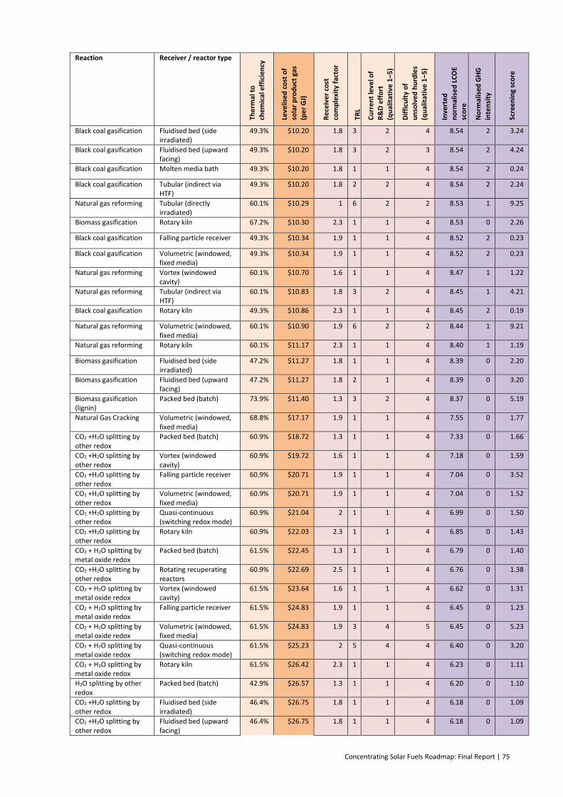
Concentrating Solar Fuels Roadmap: Final Report | 75
Reaction Receiver / reactor type
The
rmal
to
chem
ical
eff
icie
ncy
Leve
lise
d c
ost
of
sola
r p
rod
uct
gas
(p
er
GJ)
Re
ceiv
er
cost
co
mp
lexi
ty f
acto
r
TRL
Cu
rre
nt
leve
l of
R&
D e
ffo
rt
(qu
alit
ativ
e 1
–5)
Dif
ficu
lty
of
un
solv
ed
hu
rdle
s
(qu
alit
ativ
e 1
–5)
Inve
rte
d
no
rmal
ise
d L
CO
E sc
ore
No
rmal
ised
GH
G
inte
nsi
ty
Scre
en
ing
sco
re
Black coal gasification Fluidised bed (side irradiated)
49.3% $10.20 1.8 3 2 4 8.54 2 3.24
Black coal gasification Fluidised bed (upward facing)
49.3% $10.20 1.8 3 2 3 8.54 2 4.24
Black coal gasification Molten media bath 49.3% $10.20 1.8 1 1 4 8.54 2 0.24
Black coal gasification Tubular (indirect via HTF)
49.3% $10.20 1.8 2 2 4 8.54 2 2.24
Natural gas reforming Tubular (directly irradiated)
60.1% $10.29 1 6 2 2 8.53 1 9.25
Biomass gasification Rotary kiln 67.2% $10.30 2.3 1 1 4 8.53 0 2.26
Black coal gasification Falling particle receiver 49.3% $10.34 1.9 1 1 4 8.52 2 0.23
Black coal gasification Volumetric (windowed, fixed media)
49.3% $10.34 1.9 1 1 4 8.52 2 0.23
Natural gas reforming Vortex (windowed cavity)
60.1% $10.70 1.6 1 1 4 8.47 1 1.22
Natural gas reforming Tubular (indirect via HTF)
60.1% $10.83 1.8 3 2 4 8.45 1 4.21
Black coal gasification Rotary kiln 49.3% $10.86 2.3 1 1 4 8.45 2 0.19
Natural gas reforming Volumetric (windowed, fixed media)
60.1% $10.90 1.9 6 2 2 8.44 1 9.21
Natural gas reforming Rotary kiln 60.1% $11.17 2.3 1 1 4 8.40 1 1.19
Biomass gasification Fluidised bed (side irradiated)
47.2% $11.27 1.8 1 1 4 8.39 0 2.20
Biomass gasification Fluidised bed (upward facing)
47.2% $11.27 1.8 2 1 4 8.39 0 3.20
Biomass gasification (lignin)
Packed bed (batch) 73.9% $11.40 1.3 3 2 4 8.37 0 5.19
Natural Gas Cracking Volumetric (windowed, fixed media)
68.8% $17.17 1.9 1 1 4 7.55 0 1.77
CO2 +H2O splitting by other redox
Packed bed (batch) 60.9% $18.72 1.3 1 1 4 7.33 0 1.66
CO2 +H2O splitting by other redox
Vortex (windowed cavity)
60.9% $19.72 1.6 1 1 4 7.18 0 1.59
CO2 +H2O splitting by other redox
Falling particle receiver 60.9% $20.71 1.9 1 1 4 7.04 0 3.52
CO2 +H2O splitting by other redox
Volumetric (windowed, fixed media)
60.9% $20.71 1.9 1 1 4 7.04 0 1.52
CO2 +H2O splitting by other redox
Quasi-continuous (switching redox mode)
60.9% $21.04 2 1 1 4 6.99 0 1.50
CO2 +H2O splitting by other redox
Rotary kiln 60.9% $22.03 2.3 1 1 4 6.85 0 1.43
CO2 + H2O splitting by metal oxide redox
Packed bed (batch) 61.5% $22.45 1.3 1 1 4 6.79 0 1.40
CO2 +H2O splitting by other redox
Rotating recuperating reactors
60.9% $22.69 2.5 1 1 4 6.76 0 1.38
CO2 + H2O splitting by metal oxide redox
Vortex (windowed cavity)
61.5% $23.64 1.6 1 1 4 6.62 0 1.31
CO2 + H2O splitting by metal oxide redox
Falling particle receiver 61.5% $24.83 1.9 1 1 4 6.45 0 1.23
CO2 + H2O splitting by metal oxide redox
Volumetric (windowed, fixed media)
61.5% $24.83 1.9 3 4 5 6.45 0 5.23
CO2 + H2O splitting by metal oxide redox
Quasi-continuous (switching redox mode)
61.5% $25.23 2 5 4 4 6.40 0 3.20
CO2 + H2O splitting by metal oxide redox
Rotary kiln 61.5% $26.42 2.3 1 1 4 6.23 0 1.11
H2O splitting by other redox
Packed bed (batch) 42.9% $26.57 1.3 1 1 4 6.20 0 1.10
CO2 +H2O splitting by other redox
Fluidised bed (side irradiated)
46.4% $26.75 1.8 1 1 4 6.18 0 1.09
CO2 +H2O splitting by other redox
Fluidised bed (upward facing)
46.4% $26.75 1.8 1 1 4 6.18 0 1.09

76 | Concentrating Solar Fuels Roadmap: Final Report
Reaction Receiver / reactor type
The
rmal
to
chem
ical
eff
icie
ncy
Leve
lise
d c
ost
of
sola
r p
rod
uct
gas
(p
er
GJ)
Re
ceiv
er
cost
co
mp
lexi
ty f
acto
r
TRL
Cu
rre
nt
leve
l of
R&
D e
ffo
rt
(qu
alit
ativ
e 1
–5)
Dif
ficu
lty
of
un
solv
ed
hu
rdle
s
(qu
alit
ativ
e 1
–5)
Inve
rte
d
no
rmal
ise
d L
CO
E sc
ore
No
rmal
ised
GH
G
inte
nsi
ty
Scre
en
ing
sco
re
CO2 + H2O splitting by metal oxide redox
Rotating recuperating reactors
61.5% $27.21 2.5 1 1 4 6.11 0 1.06
H2O splitting by other redox
Vortex (windowed cavity)
42.9% $27.98 1.6 1 1 4 6.00 0 1.00
Natural Gas Cracking Vortex (windowed cavity)
68.8% $28.78 1.6 1 1 4 5.89 0 0.94
CO2 + H2O splitting by metal oxide redox
Fluidised bed (side irradiated)
47.0% $29.12 1.8 1 1 4 5.84 0 0.92
CO2 + H2O splitting by metal oxide redox
Fluidised bed (upward facing)
47.0% $29.12 1.8 1 1 4 5.84 0 0.92
H2O splitting by metal oxide redox
Packed bed (batch) 44.5% $29.36 1 1 1 1 5.81 0 3.90
H2O splitting by other redox
Volumetric (windowed, fixed media)
42.9% $29.38 1.9 4 3 4 5.80 0 5.90
H2O splitting by other redox
Quasi-continuous (switching redox mode)
42.9% $29.85 2 1 1 4 5.74 0 0.87
H2O splitting by metal oxide redox
Packed bed (batch) 44.5% $31.00 1.3 1 1 4 5.57 0 0.79
H2O splitting by other redox
Rotary kiln 42.9% $31.26 2.3 1 1 4 5.53 0 0.77
H2O splitting by other redox
Rotating recuperating reactors
42.9% $32.20 2.5 1 1 4 5.40 0 0.70
H2O splitting by metal oxide redox
Vortex (windowed cavity)
44.5% $32.64 1.6 1 1 4 5.34 0 0.67
H2O splitting by metal oxide redox
Falling particle receiver 44.5% $34.28 1.9 1 1 5 5.10 0 -0.45
H2O splitting by metal oxide redox
Volumetric (windowed, fixed media)
44.5% $34.28 1.9 5 4 4 5.10 0 7.55
H2O splitting by metal oxide redox
Quasi-continuous (switching redox mode)
44.5% $34.83 2 5 4 4 5.02 0 7.51
H2O splitting by metal oxide redox
Rotary kiln 44.5% $36.47 2.3 1 1 4 4.79 0 0.39
H2O splitting by metal oxide redox
Rotating recuperating reactors
44.5% $37.57 2.5 4 2 4 4.63 0 4.32
H2O splitting by other redox
Fluidised bed (upward facing)
29.2% $42.53 1.8 1 1 4 3.92 0 -0.04
H2O splitting by metal oxide redox
Fluidised bed (side irradiated)
29.5% $46.46 1.8 1 1 4 3.36 0 -0.32
GHG = greenhouse gas; HTF = heat transfer fluid; TRL = technology readiness level
Table 13 shows that the lowest LCOF is projected for waste material in a tubular or packed be
reactor, with the third-lowest being brown coal (also converted in a tubular reactor). This is an
understandable result, given that these options have the lowest feedstock costs – assumed to be
zero for waste and $1/GJ for brown coal. The tubular reactor has also been estimated as the
cheapest reactor option in principle.
The other brown coal and waste receiver processing options appear variously down the list in a
rank order that approximately follows reactor cost estimates. Note that there is nothing definitive
about this ordering between reactor types. R&D developments with any one of those reactors or
indeed new reactor concepts could easily see a new ‘front runner’ reactor type. Note also that at
this stage, the assessed inputs of operating temperature do not distinguish between reactor types
for a particular reaction. Thus, technical developments that allow a particular reactor design to
operate at a lower temperature could reduce the LCOF enough to outweigh a more expensive
receiver reactor.

Concentrating Solar Fuels Roadmap: Final Report | 77
An exception to this, however, is the appearance of the fluidised bed options at the bottom of the
rank order for brown coal and waste conversion. Use of a fluidised bed is associated with the
assumption that a significant inert gas stream is needed to maintain the fluidisation of particles.
The imperfect recuperation of sensible heat from this stream of inert gas has lowered the thermal-
to-chemical efficiency to pull this option down the rank order. This indicates that pursuit of the
fluidised bed option requires other benefits – such as better heat transfer, leading to lower
operating temperatures – to outweigh the energy cost of recycling the inert gases.
Biomass gasification in a packed bed reactor is the lowest cost option (~$10/GJ) that also has a
greenhouse gas intensity score of zero. Natural gas cracking also has a zero GHG score based on
the assumption that the pure carbon produced is never combusted, but is considerable more
expensive ($17/GJ of H2). It is the only hybrid fossil fuel option that can claim zero GHG emissions
without complex sequestration of CO2. Running counter to this, however, is a potential
commercial market for carbon black, which could offer a lower LCOF. This is probably only possible
at a niche scale, however, since large-scale production would soon swamp the existing carbon
black market. The expert panel also noted that carbon black from solar methane cracking may be a
difficult product to either sell or bury in land, fill due to concerns about hydrocarbon contaminants
such as polycyclic aromatic hydrocarbons.
The remainder of the solar hybrid options appear in an order that reflects the combination of their
input fuel costs, receiver reactor cost and any extra energy recuperation challenges. The ordering
of these alternatives should not be taken as in any way absolute, but rather used as an indicator of
the areas requiring more effort in R&D activities.
The lowest-cost pure solar option comes in at $19/GJ and the highest at $46/GJ. Considerable
differences have been identified in the levels of secondary reactants and gas phase material
requiring thermal recuperation. Again, the order is subject to change as R&D continues. However,
it seems unlikely that the highest cost options would ever be able to catch up with the lower-cost
ones in this way, so some major pragmatic issues would need to come into play to favour them.
Ranking the options on the calculated weighted screening score changes the ordering
considerably, as can be seen in Table 14, which shows the 25 top ranked options.
Table 14: Highest ranked technologies from techno-economic analysis screening
Reaction Receiver / reactor type
The
rmal
to
ch
emic
al e
ffic
ien
cy
Leve
lise
d c
ost
of
sola
r p
rod
uct
gas
(pe
r G
J)
Re
ceiv
er
cost
com
ple
xity
fac
tor
TRL
Cu
rre
nt
leve
l of
R&
D e
ffo
rt
(qu
alit
ativ
e 1
–5)
Dif
ficu
lty
of
un
solv
ed
hu
rdle
s
(qu
alit
ativ
e 1
–5)
Inve
rte
d
no
rmal
ise
d L
CO
E
sco
re
No
rmal
ised
GH
G
inte
nsi
ty
Scre
en
ing
sco
re
Natural gas reforming Tubular (directly irradiated)
60.1% $10.29 1 6 2 2 8.53 1 9.25
Natural gas reforming Volumetric (windowed, fixed media)
60.1% $10.90 1.9 6 2 2 8.44 1 9.21
CO2 + H2O splitting by metal oxide redox
Quasi-continuous (switching redox mode)
61.5% $25.23 2 5 4 4 6.40 0 8.20
H2O splitting by metal oxide redox
Volumetric (windowed, fixed media)
44.5% $34.28 1.9 5 4 4 5.10 0 7.55
H2O splitting by metal oxide redox
Quasi-continuous (switching redox mode)
44.5% $34.83 2 5 4 4 5.02 0 7.51
H2O splitting by other redox
Volumetric (windowed, fixed media)
42.9% $29.38 1.9 4 3 4 5.80 0 5.90
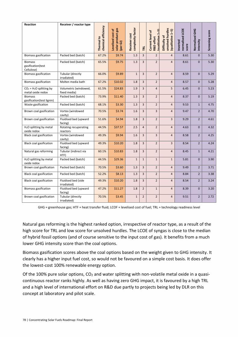
78 | Concentrating Solar Fuels Roadmap: Final Report
Reaction Receiver / reactor type
The
rmal
to
ch
emic
al e
ffic
ien
cy
Leve
lise
d c
ost
of
sola
r p
rod
uct
gas
(pe
r G
J)
Re
ceiv
er
cost
com
ple
xity
fac
tor
TRL
Cu
rre
nt
leve
l of
R&
D e
ffo
rt
(qu
alit
ativ
e 1
–5)
Dif
ficu
lty
of
un
solv
ed
hu
rdle
s
(qu
alit
ativ
e 1
–5)
Inve
rte
d
no
rmal
ise
d L
CO
E
sco
re
No
rmal
ised
GH
G
inte
nsi
ty
Scre
en
ing
sco
re
Biomass gasification Packed bed (batch) 67.2% $9.74 1.3 3 2 4 8.61 0 5.30
Biomass gasification(test Cellulose)
Packed bed (batch) 65.5% $9.75 1.3 3 2 4 8.61 0 5.30
Biomass gasification Tubular (directly irradiated)
66.0% $9.89 1 3 2 4 8.59 0 5.29
Biomass gasification Molten media bath 67.2% $10.02 1.8 3 2 4 8.57 0 5.28
CO2 + H2O splitting by metal oxide redox
Volumetric (windowed, fixed media)
61.5% $24.83 1.9 3 4 5 6.45 0 5.23
Biomass gasification(test lignin)
Packed bed (batch) 73.9% $11.40 1.3 3 2 4 8.37 0 5.19
Waste gasification Packed bed (batch) 68.1% $3.30 1.3 3 2 4 9.53 1 4.75
Brown coal gasification Vortex (windowed cavity)
70.5% $3.74 1.6 3 3 4 9.47 2 4.70
Brown coal gasification Fluidised bed (upward facing)
51.6% $4.94 1.8 3 2 3 9.29 2 4.61
H2O splitting by metal oxide redox
Rotating recuperating reactors
44.5% $37.57 2.5 4 2 4 4.63 0 4.32
Black coal gasification Vortex (windowed cavity)
49.3% $9.94 1.6 3 3 4 8.58 2 4.25
Black coal gasification Fluidised bed (upward facing)
49.3% $10.20 1.8 3 2 3 8.54 2 4.24
Natural gas reforming Tubular (indirect via HTF)
60.1% $10.83 1.8 3 2 4 8.45 1 4.21
H2O splitting by metal oxide redox
Packed bed (batch) 44.5% $29.36 1 1 1 1 5.81 0 3.90
Brown coal gasification Packed bed (batch) 70.5% $3.60 1.3 3 2 4 9.49 2 3.71
Black coal gasification Packed bed (batch) 52.2% $8.13 1.3 3 2 4 8.84 2 3.38
Black coal gasification Fluidised bed (side irradiated)
49.3% $10.20 1.8 3 2 4 8.54 2 3.24
Biomass gasification Fluidised bed (upward facing)
47.2% $11.27 1.8 2 1 4 8.39 0 3.20
Brown coal gasification Tubular (directly irradiated)
70.5% $3.45 1 2 2 4 9.51 2 2.72
GHG = greenhouse gas; HTF = heat transfer fluid; LCOF = levelised cost of fuel; TRL = technology readiness level
Natural gas reforming is the highest ranked option, irrespective of reactor type, as a result of the
high score for TRL and low score for unsolved hurdles. The LCOE of syngas is close to the median
of hybrid fossil options (and of course sensitive to the input cost of gas). It benefits from a much
lower GHG intensity score than the coal options.
Biomass gasification scores above the coal options based on the weight given to GHG intensity. It
clearly has a higher input fuel cost, so would not be favoured on a simple cost basis. It does offer
the lowest-cost 100% renewable energy option.
Of the 100% pure solar options, CO2 and water splitting with non-volatile metal oxide in a quasi-
continuous reactor ranks highly. As well as having zero GHG impact, it is favoured by a high TRL
and a high level of international effort on R&D due partly to projects being led by DLR on this
concept at laboratory and pilot scale.
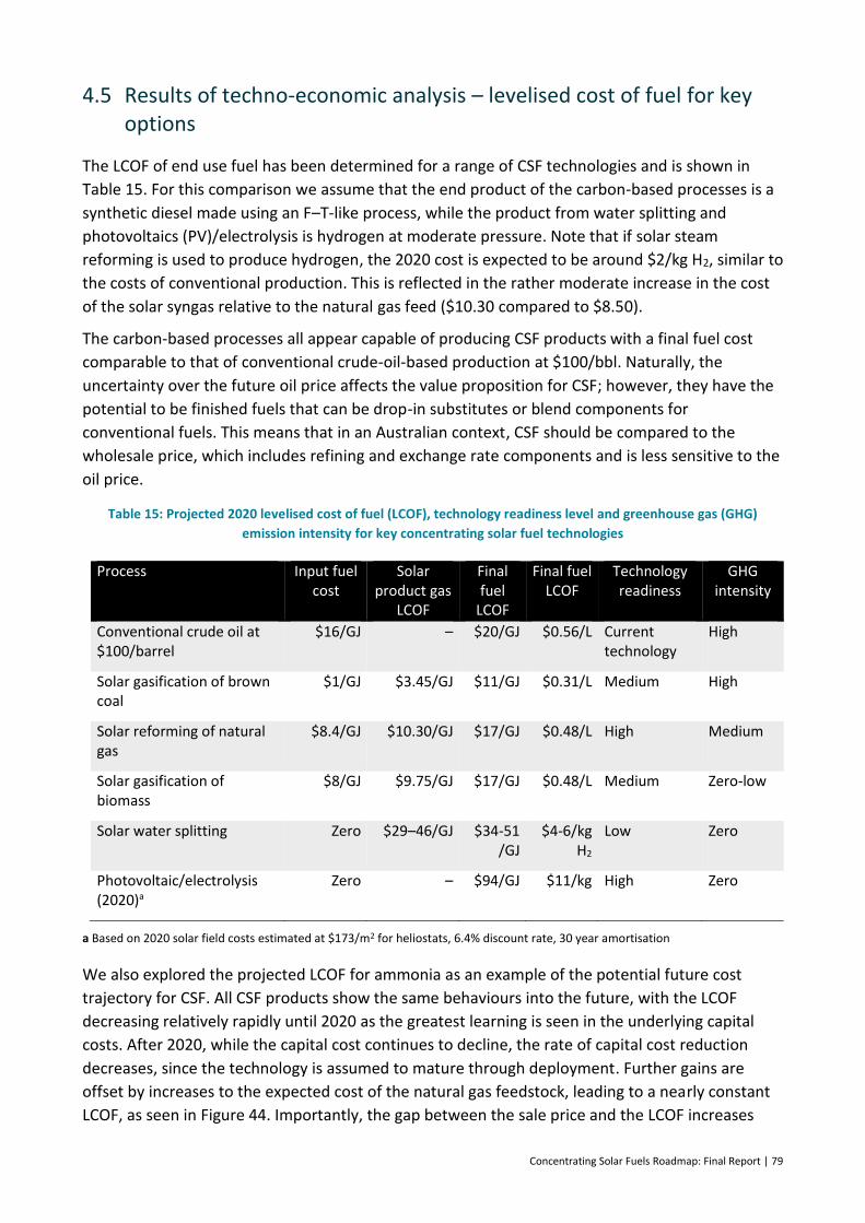
Concentrating Solar Fuels Roadmap: Final Report | 79
4.5 Results of techno-economic analysis – levelised cost of fuel for key options
The LCOF of end use fuel has been determined for a range of CSF technologies and is shown in
Table 15. For this comparison we assume that the end product of the carbon-based processes is a
synthetic diesel made using an F–T-like process, while the product from water splitting and
photovoltaics (PV)/electrolysis is hydrogen at moderate pressure. Note that if solar steam
reforming is used to produce hydrogen, the 2020 cost is expected to be around $2/kg H2, similar to
the costs of conventional production. This is reflected in the rather moderate increase in the cost
of the solar syngas relative to the natural gas feed ($10.30 compared to $8.50).
The carbon-based processes all appear capable of producing CSF products with a final fuel cost
comparable to that of conventional crude-oil-based production at $100/bbl. Naturally, the
uncertainty over the future oil price affects the value proposition for CSF; however, they have the
potential to be finished fuels that can be drop-in substitutes or blend components for
conventional fuels. This means that in an Australian context, CSF should be compared to the
wholesale price, which includes refining and exchange rate components and is less sensitive to the
oil price.
Table 15: Projected 2020 levelised cost of fuel (LCOF), technology readiness level and greenhouse gas (GHG)
emission intensity for key concentrating solar fuel technologies
Process Input fuel cost
Solar product gas
LCOF
Final fuel
LCOF
Final fuel LCOF
Technology readiness
GHG intensity
Conventional crude oil at $100/barrel
$16/GJ – $20/GJ $0.56/L Current technology
High
Solar gasification of brown coal
$1/GJ $3.45/GJ $11/GJ $0.31/L Medium High
Solar reforming of natural gas
$8.4/GJ $10.30/GJ $17/GJ $0.48/L High Medium
Solar gasification of biomass
$8/GJ $9.75/GJ $17/GJ $0.48/L Medium Zero-low
Solar water splitting Zero $29–46/GJ $34-51 /GJ
$4-6/kg H2
Low Zero
Photovoltaic/electrolysis (2020)a
Zero – $94/GJ $11/kg High Zero
a Based on 2020 solar field costs estimated at $173/m2 for heliostats, 6.4% discount rate, 30 year amortisation
We also explored the projected LCOF for ammonia as an example of the potential future cost
trajectory for CSF. All CSF products show the same behaviours into the future, with the LCOF
decreasing relatively rapidly until 2020 as the greatest learning is seen in the underlying capital
costs. After 2020, while the capital cost continues to decline, the rate of capital cost reduction
decreases, since the technology is assumed to mature through deployment. Further gains are
offset by increases to the expected cost of the natural gas feedstock, leading to a nearly constant
LCOF, as seen in Figure 44. Importantly, the gap between the sale price and the LCOF increases
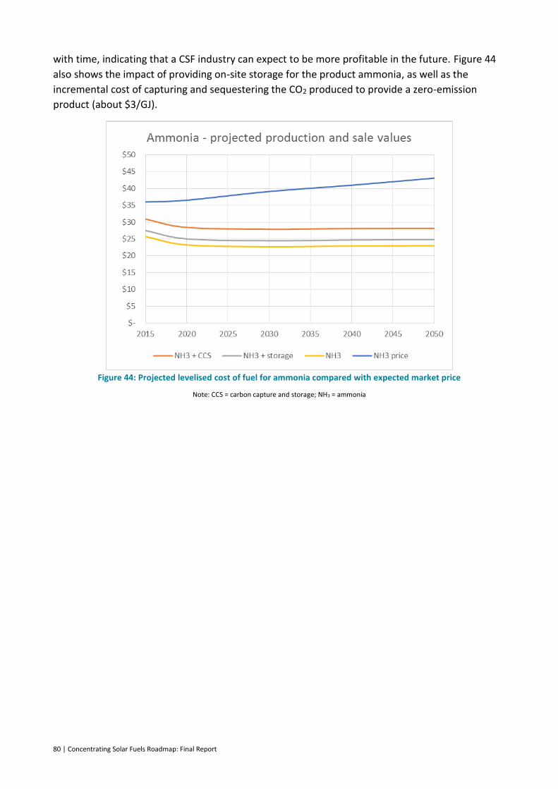
80 | Concentrating Solar Fuels Roadmap: Final Report
with time, indicating that a CSF industry can expect to be more profitable in the future. Figure 44
also shows the impact of providing on-site storage for the product ammonia, as well as the
incremental cost of capturing and sequestering the CO2 produced to provide a zero-emission
product (about $3/GJ).
Figure 44: Projected levelised cost of fuel for ammonia compared with expected market price
Note: CCS = carbon capture and storage; NH3 = ammonia
Concentrating Solar Fuels Roadmap: Final Report | 81
5 Case studies of potential business opportunities
Solar steam reforming of methane (SRM) is currently the most advanced solar fuel technology,
and therefore represents the most prospective commercial opportunity. We performed a case
study financial analysis on this technology coupled to various fuel conversion technologies that
can produce a range of fuel products.
Solar SRM requires both a good direct normal irradiance (DNI) and a source of natural gas, both of
which are in abundance in the Fitzroy region of Queensland; in particular, in the port of Gladstone,
where natural gas is being converted to LNG for export to Australia’s Asian trading partners (see
Section 3.5). Therefore, our case study will focus on using solar SRM in Gladstone.
We assume that all products will be sold in export markets, except for diesel, which is suitable for
local use and has a market value in Australia (Section 3.3). While the analysis involves a single solar
SRM facility, the number of facilities can be scaled up to provide a regional industry perspective.
Higher DNI is available away from the coast, in the Fitzroy; however, Gladstone has the advantage
of port facilities with access to utilities, feedstocks and a considerable workforce. If the industry
was to be scaled up, then it would make economic sense to locate the solar facilities in the regions
with the best DNI and provide any infrastructure necessary for transporting the solar fuel to the
port for export.
5.1 Capital, operating and maintenance cost and production assumptions
We have assumed that the solar SRM facility that produces syngas is common to all processes.
However, the fuel conversion processes (from syngas to a final fuel) differ, as described in
Section 2.8, and thus have different cost assumptions. The solar capital and operating and
maintenance (O&M) costs have been described in detail previously, and thus are only summarised
here in Table 16 (Hinkley et al., 2015b). The costs are for a 50-MWth solar facility in the year 2020.
They do not include indirect costs or contingency, which are 25% of capital. These costs need to be
included for the financial analysis and levelised cost calculations.
Daily syngas production has been calculated to be 2170 GJ. Syngas storage is included, allowing
the fuel production facility to run with a 75% capacity factor. This has been assumed so that the
fuel production facilities can run continuously, albeit with much lower production at night. Fuel
production facilities need to run continuously, because start-up and shutdown procedures can
take several hours, which will affect both output and lifetime of plant components due to material
fatigue (Saw, W 2015, pers. comm. Nov. 2015)
Electricity generation has also been included in the cost, to take advantage of the waste heat from
several of the fuel processes and generate additional revenue. We have assumed that electricity is
sold to the grid for $80/MWh.
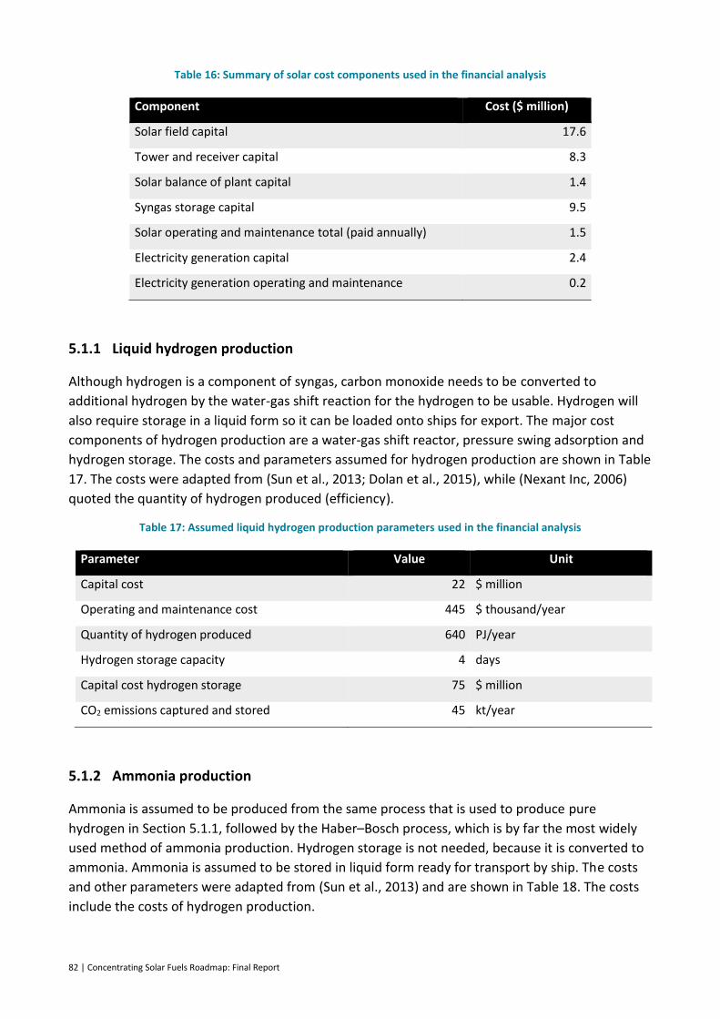
82 | Concentrating Solar Fuels Roadmap: Final Report
Table 16: Summary of solar cost components used in the financial analysis
Component Cost ($ million)
Solar field capital 17.6
Tower and receiver capital 8.3
Solar balance of plant capital 1.4
Syngas storage capital 9.5
Solar operating and maintenance total (paid annually) 1.5
Electricity generation capital 2.4
Electricity generation operating and maintenance 0.2
5.1.1 Liquid hydrogen production
Although hydrogen is a component of syngas, carbon monoxide needs to be converted to
additional hydrogen by the water-gas shift reaction for the hydrogen to be usable. Hydrogen will
also require storage in a liquid form so it can be loaded onto ships for export. The major cost
components of hydrogen production are a water-gas shift reactor, pressure swing adsorption and
hydrogen storage. The costs and parameters assumed for hydrogen production are shown in Table
17. The costs were adapted from (Sun et al., 2013; Dolan et al., 2015), while (Nexant Inc, 2006)
quoted the quantity of hydrogen produced (efficiency).
Table 17: Assumed liquid hydrogen production parameters used in the financial analysis
Parameter Value Unit
Capital cost 22 $ million
Operating and maintenance cost 445 $ thousand/year
Quantity of hydrogen produced 640 PJ/year
Hydrogen storage capacity 4 days
Capital cost hydrogen storage 75 $ million
CO2 emissions captured and stored 45 kt/year
5.1.2 Ammonia production
Ammonia is assumed to be produced from the same process that is used to produce pure
hydrogen in Section 5.1.1, followed by the Haber–Bosch process, which is by far the most widely
used method of ammonia production. Hydrogen storage is not needed, because it is converted to
ammonia. Ammonia is assumed to be stored in liquid form ready for transport by ship. The costs
and other parameters were adapted from (Sun et al., 2013) and are shown in Table 18. The costs
include the costs of hydrogen production.

Concentrating Solar Fuels Roadmap: Final Report | 83
Table 18: Assumed ammonia production parameters used in the financial analysis
Parameter Value Unit
Capital cost 38 $ million
Operating and maintenance (O&M) cost 1 $ million/year
Quantity of ammonia produced 600 PJ/year
Ammonia storage capacity 4 days
Ammonia storage capital cost 8 $ million
Ammonia storage O&M cost 310 $ thousand/year
CO2 emissions captured and stored 45 kt/year
5.1.3 Diesel production
Diesel (and potentially other ‘drop-in’ fuels) are produced from syngas using the Fischer–Tropsch
(F–T) process. This process is exothermic; the excess heat can be used to produce electricity and
thus generate additional revenue for the plant. Therefore, costs of electricity production have
been included. Because we assume that the diesel is sold locally, diesel storage has not been
included in the cost estimates. The costs and other parameters are shown in Table 19 and were
developed by harmonising costs from various F–T liquid studies (Shuster, 2013; Van Bibber et al.,
2007; Swanson et al., 2010).
Table 19: Assumed diesel production parameters used in the financial analysis
Parameter Value Unit
Capital cost 21 $ million
Operating and maintenance (O&M) cost 410 $ thousand/year
Quantity of diesel produced 600 PJ/year
Electricity generation capital cost 2 $ million
Electricity generation O&M cost 180 $ thousand/year
Quantity of electricity produced 15 GWh/year
5.1.4 Methanol production
Methanol is produced from syngas using a process used in the petrochemical industry. As for the
F–T process, the methanol process is exothermic, and thus excess heat can be used to produce
electricity. The costs and other parameters are shown in Table 20, except for the electricity
generation costs, which are the same as those in Table 19. The parameters were developed by
harmonising results from different studies (Phillips et al., 2011; Worley Parsons, 2014).
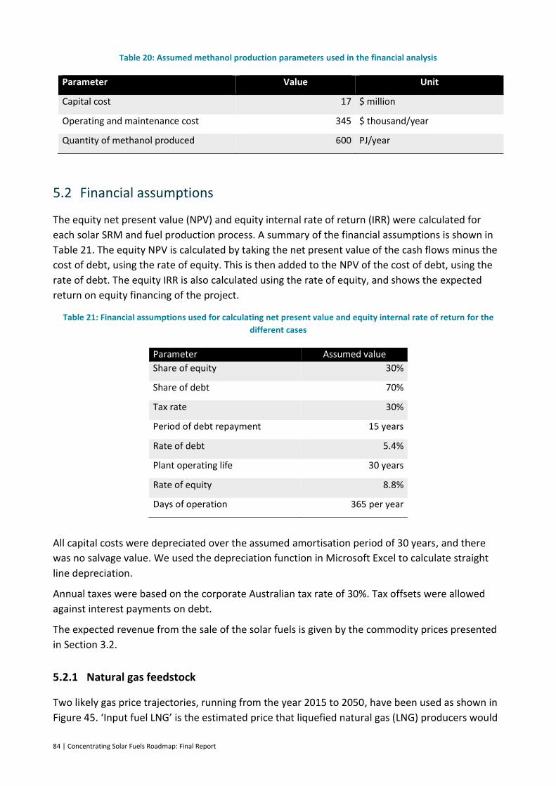
84 | Concentrating Solar Fuels Roadmap: Final Report
Table 20: Assumed methanol production parameters used in the financial analysis
Parameter Value Unit
Capital cost 17 $ million
Operating and maintenance cost 345 $ thousand/year
Quantity of methanol produced 600 PJ/year
5.2 Financial assumptions
The equity net present value (NPV) and equity internal rate of return (IRR) were calculated for
each solar SRM and fuel production process. A summary of the financial assumptions is shown in
Table 21. The equity NPV is calculated by taking the net present value of the cash flows minus the
cost of debt, using the rate of equity. This is then added to the NPV of the cost of debt, using the
rate of debt. The equity IRR is also calculated using the rate of equity, and shows the expected
return on equity financing of the project.
Table 21: Financial assumptions used for calculating net present value and equity internal rate of return for the
different cases
Parameter Assumed value
Share of equity 30%
Share of debt 70%
Tax rate 30%
Period of debt repayment 15 years
Rate of debt 5.4%
Plant operating life 30 years
Rate of equity 8.8%
Days of operation 365 per year
All capital costs were depreciated over the assumed amortisation period of 30 years, and there
was no salvage value. We used the depreciation function in Microsoft Excel to calculate straight
line depreciation.
Annual taxes were based on the corporate Australian tax rate of 30%. Tax offsets were allowed
against interest payments on debt.
The expected revenue from the sale of the solar fuels is given by the commodity prices presented
in Section 3.2.
5.2.1 Natural gas feedstock
Two likely gas price trajectories, running from the year 2015 to 2050, have been used as shown in
Figure 45. ‘Input fuel LNG’ is the estimated price that liquefied natural gas (LNG) producers would

Concentrating Solar Fuels Roadmap: Final Report | 85
have to pay before liquefying the gas (Wagner, 2014). The second trajectory is the projected
wholesale price of gas. This is the price that local users of gas, such as electricity generation plants,
would have to pay (Graham et al., 2015). These are different from the LNG prices shown in Figure
23, because they represent local prices rather than exported prices. Local prices are appropriate as
a feedstock price, since that is what a local industrial buyer would pay for their gas supply.
Figure 45: Projected gas price used in the financial analysis
5.2.2 Shipping
The export commodities analysis includes shipping, the expected prices of which are based on
those of LNG (Jefferies, 2013; Core Energy Group, 2013). The prices have been scaled to take into
account the different energy contents and shipping requirements of the different fuels, and are
presented in Table 22. The maximum value for shipping liquid hydrogen is consistent with that
being proposed by Kawasaki Corporation, which includes the cost of building new ships (Kodama,
2013).
Table 22: Shipping prices for solar fuels used in the financial analysis
Fuel Minimum ($/GJ) Maximum ($/GJ) Average ($/GJ)
Liquefied natural gas (for reference) 1.00 3.61 2.31
Liquefied hydrogen 2.61 9.42 6.02
Ammonia 1.93 6.97 4.45
Methanol 1.42 5.13 3.28
0
2
4
6
8
10
12
14
2020 2025 2030 2035 2040 2045 2050
Pro
ject
ed
gas
pri
ce (
$/G
J)
Input fuel LNG Wholesale gas price
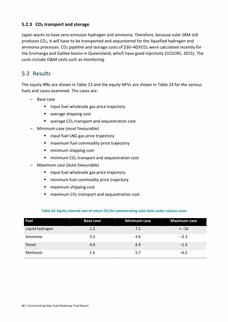
86 | Concentrating Solar Fuels Roadmap: Final Report
5.2.3 CO2 transport and storage
Japan wants to have zero-emission hydrogen and ammonia. Therefore, because solar SRM still
produces CO2, it will have to be transported and sequestered for the liquefied hydrogen and
ammonia processes. CO2 pipeline and storage costs of $30–40/tCO2 were calculated recently for
the Eromanga and Galilee basins in Queensland, which have good injectivity (CO2CRC, 2015). The
costs include O&M costs such as monitoring.
5.3 Results
The equity IRRs are shown in Table 23 and the equity NPVs are shown in Table 24 for the various
fuels and cases examined. The cases are:
– Base case
input fuel wholesale gas price trajectory
average shipping cost
average CO2 transport and sequestration cost
– Minimum case (most favourable)
input fuel LNG gas price trajectory
maximum fuel commodity price trajectory
minimum shipping cost
minimum CO2 transport and sequestration cost
– Maximum case (least favourable)
input fuel wholesale gas price trajectory
minimum fuel commodity price trajectory
maximum shipping cost
maximum CO2 transport and sequestration cost.
Table 23: Equity internal rate of return (%) for concentrating solar fuels under various cases
Fuel Base case Minimum case Maximum case
Liquid hydrogen 1.2 7.1 < –10
Ammonia 3.2 4.6 –2.3
Diesel 4.0 6.4 –1.5
Methanol 1.6 5.7 –6.2
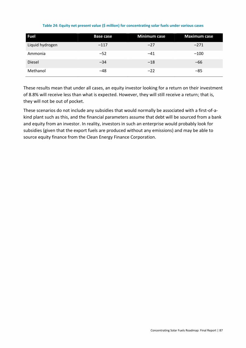
Concentrating Solar Fuels Roadmap: Final Report | 87
Table 24: Equity net present value ($ million) for concentrating solar fuels under various cases
Fuel Base case Minimum case Maximum case
Liquid hydrogen –117 –27 –271
Ammonia –52 –41 –100
Diesel –34 –18 –66
Methanol –48 –22 –85
These results mean that under all cases, an equity investor looking for a return on their investment
of 8.8% will receive less than what is expected. However, they will still receive a return; that is,
they will not be out of pocket.
These scenarios do not include any subsidies that would normally be associated with a first-of-a-
kind plant such as this, and the financial parameters assume that debt will be sourced from a bank
and equity from an investor. In reality, investors in such an enterprise would probably look for
subsidies (given that the export fuels are produced without any emissions) and may be able to
source equity finance from the Clean Energy Finance Corporation.
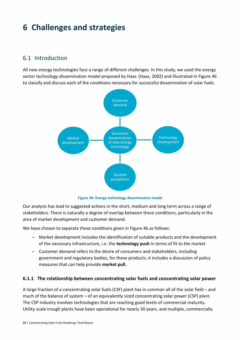
88 | Concentrating Solar Fuels Roadmap: Final Report
6 Challenges and strategies
6.1 Introduction
All new energy technologies face a range of different challenges. In this study, we used the energy
sector technology dissemination model proposed by Haas (Haas, 2002) and illustrated in Figure 46
to classify and discuss each of the conditions necessary for successful dissemination of solar fuels.
Figure 46: Energy technology dissemination model
Our analysis has lead to suggested actions in the short, medium and long term across a range of
stakeholders. There is naturally a degree of overlap between these conditions, particularly in the
area of market development and customer demand.
We have chosen to separate these conditions given in Figure 46 as follows:
– Market development includes the identification of suitable products and the development
of the necessary infrastructure, i.e. the technology push in terms of fit to the market
– Customer demand refers to the desire of consumers and stakeholders, including
government and regulatory bodies, for these products; it includes a discussion of policy
measures that can help provide market pull.
6.1.1 The relationship between concentrating solar fuels and concentrating solar power
A large fraction of a concentrating solar fuels (CSF) plant has in common all of the solar field – and
much of the balance of system – of an equivalently sized concentrating solar power (CSP) plant.
The CSP industry involves technologies that are reaching good levels of commercial maturity.
Utility-scale trough plants have been operational for nearly 30 years, and multiple, commercially
Successful dissemination of new energy
technology
Customer demand
Technology development
Societal acceptance
Market development
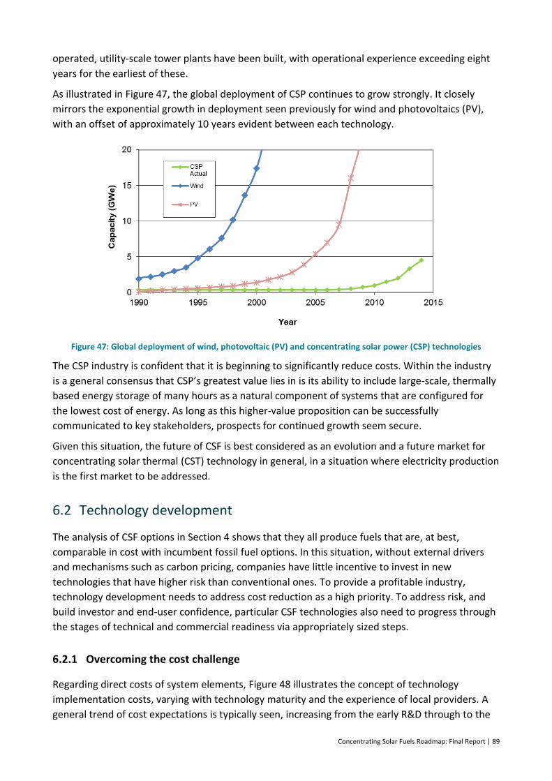
Concentrating Solar Fuels Roadmap: Final Report | 89
operated, utility-scale tower plants have been built, with operational experience exceeding eight
years for the earliest of these.
As illustrated in Figure 47, the global deployment of CSP continues to grow strongly. It closely
mirrors the exponential growth in deployment seen previously for wind and photovoltaics (PV),
with an offset of approximately 10 years evident between each technology.
Figure 47: Global deployment of wind, photovoltaic (PV) and concentrating solar power (CSP) technologies
The CSP industry is confident that it is beginning to significantly reduce costs. Within the industry
is a general consensus that CSP’s greatest value lies in is its ability to include large-scale, thermally
based energy storage of many hours as a natural component of systems that are configured for
the lowest cost of energy. As long as this higher-value proposition can be successfully
communicated to key stakeholders, prospects for continued growth seem secure.
Given this situation, the future of CSF is best considered as an evolution and a future market for
concentrating solar thermal (CST) technology in general, in a situation where electricity production
is the first market to be addressed.
6.2 Technology development
The analysis of CSF options in Section 4 shows that they all produce fuels that are, at best,
comparable in cost with incumbent fossil fuel options. In this situation, without external drivers
and mechanisms such as carbon pricing, companies have little incentive to invest in new
technologies that have higher risk than conventional ones. To provide a profitable industry,
technology development needs to address cost reduction as a high priority. To address risk, and
build investor and end-user confidence, particular CSF technologies also need to progress through
the stages of technical and commercial readiness via appropriately sized steps.
6.2.1 Overcoming the cost challenge
Regarding direct costs of system elements, Figure 48 illustrates the concept of technology
implementation costs, varying with technology maturity and the experience of local providers. A
general trend of cost expectations is typically seen, increasing from the early R&D through to the

90 | Concentrating Solar Fuels Roadmap: Final Report
first commercial pilots. This reflects the almost universal experience that as detail is further
explored, more cost contributions come to light: in other words, things are usually harder than
they first seem. Once the data from the first commercial system is available, technical
improvement and efficiencies in manufacture continue from that starting point. A learning-curve-
based cost reduction trajectory can be expected, with an approximately constant fractional cost
reduction with every doubling of installed capacity. Eventually, costs are expected to level off at a
point that is determined by materials and physical constraints.
Figure 48: Typical cost variations for commercialising new power technologies Source: Electric Power Research Institute, 2009
In the context of CSF, this picture is made more complex by the key cost-determining subsystems,
described below, all being at different stages of development.
Solar field
Solar field components are now quite mature, since they form the major part of commercially
deployed CSP systems. They are at the beginning of what is expected to be a consistent cost
reduction trajectory following a learning curve model. This cost reduction is expected from
technical improvements and more efficient manufacturing, with scale and costs savings from
increasingly larger systems being deployed.
Receiver reactor
The receiver reactor subsystem is the heart of a CSF process. As has been described, much of the
work in this area is still in the laboratory phase, with a few systems now having progressed to the
point of small pilot installations.
Solar product gas storage
Storage of solar product gas at some level would be needed to moderate the variability of
production from solar input. Whilst pressurised gas storage is available in a number of forms, it is
expensive and can be a major contributor to LCOF. Innovative ideas exist for low cost underground
storage of gases. These have been applied to analogous purposes such as natural gas storage,
however work is needed to confirm the best approach for hydrogen and syngas mixtures.
Fuel synthesis
In most approaches, fuel synthesis technologies are an adaptation of technologies from existing
chemical and petrochemical industries. In this sense, they are quite mature; however, many
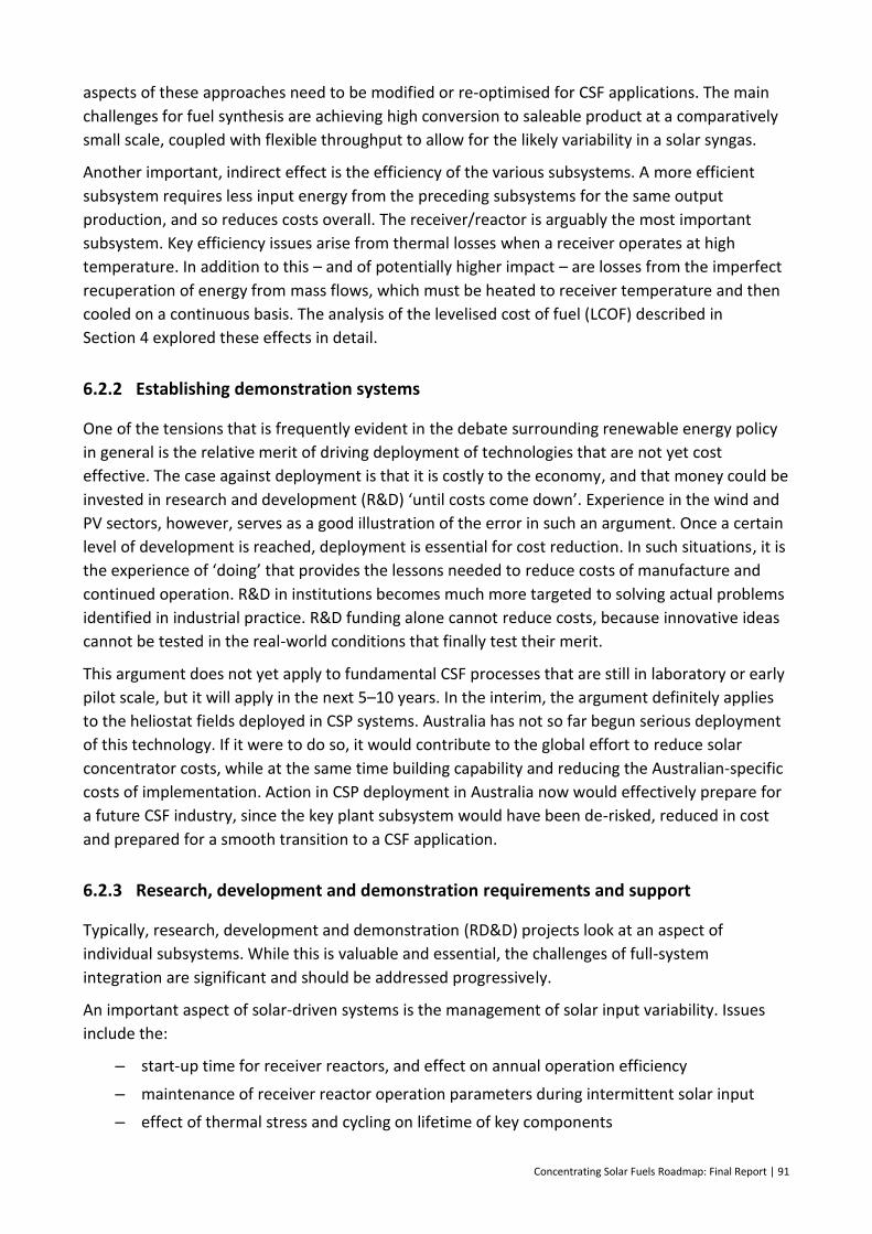
Concentrating Solar Fuels Roadmap: Final Report | 91
aspects of these approaches need to be modified or re-optimised for CSF applications. The main
challenges for fuel synthesis are achieving high conversion to saleable product at a comparatively
small scale, coupled with flexible throughput to allow for the likely variability in a solar syngas.
Another important, indirect effect is the efficiency of the various subsystems. A more efficient
subsystem requires less input energy from the preceding subsystems for the same output
production, and so reduces costs overall. The receiver/reactor is arguably the most important
subsystem. Key efficiency issues arise from thermal losses when a receiver operates at high
temperature. In addition to this – and of potentially higher impact – are losses from the imperfect
recuperation of energy from mass flows, which must be heated to receiver temperature and then
cooled on a continuous basis. The analysis of the levelised cost of fuel (LCOF) described in
Section 4 explored these effects in detail.
6.2.2 Establishing demonstration systems
One of the tensions that is frequently evident in the debate surrounding renewable energy policy
in general is the relative merit of driving deployment of technologies that are not yet cost
effective. The case against deployment is that it is costly to the economy, and that money could be
invested in research and development (R&D) ‘until costs come down’. Experience in the wind and
PV sectors, however, serves as a good illustration of the error in such an argument. Once a certain
level of development is reached, deployment is essential for cost reduction. In such situations, it is
the experience of ‘doing’ that provides the lessons needed to reduce costs of manufacture and
continued operation. R&D in institutions becomes much more targeted to solving actual problems
identified in industrial practice. R&D funding alone cannot reduce costs, because innovative ideas
cannot be tested in the real-world conditions that finally test their merit.
This argument does not yet apply to fundamental CSF processes that are still in laboratory or early
pilot scale, but it will apply in the next 5–10 years. In the interim, the argument definitely applies
to the heliostat fields deployed in CSP systems. Australia has not so far begun serious deployment
of this technology. If it were to do so, it would contribute to the global effort to reduce solar
concentrator costs, while at the same time building capability and reducing the Australian-specific
costs of implementation. Action in CSP deployment in Australia now would effectively prepare for
a future CSF industry, since the key plant subsystem would have been de-risked, reduced in cost
and prepared for a smooth transition to a CSF application.
6.2.3 Research, development and demonstration requirements and support
Typically, research, development and demonstration (RD&D) projects look at an aspect of
individual subsystems. While this is valuable and essential, the challenges of full-system
integration are significant and should be addressed progressively.
An important aspect of solar-driven systems is the management of solar input variability. Issues
include the:
– start-up time for receiver reactors, and effect on annual operation efficiency
– maintenance of receiver reactor operation parameters during intermittent solar input
– effect of thermal stress and cycling on lifetime of key components
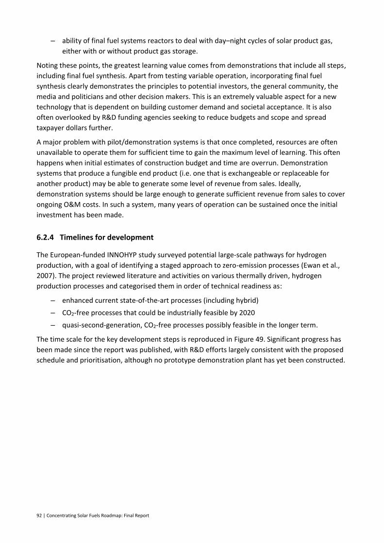
92 | Concentrating Solar Fuels Roadmap: Final Report
– ability of final fuel systems reactors to deal with day–night cycles of solar product gas,
either with or without product gas storage.
Noting these points, the greatest learning value comes from demonstrations that include all steps,
including final fuel synthesis. Apart from testing variable operation, incorporating final fuel
synthesis clearly demonstrates the principles to potential investors, the general community, the
media and politicians and other decision makers. This is an extremely valuable aspect for a new
technology that is dependent on building customer demand and societal acceptance. It is also
often overlooked by R&D funding agencies seeking to reduce budgets and scope and spread
taxpayer dollars further.
A major problem with pilot/demonstration systems is that once completed, resources are often
unavailable to operate them for sufficient time to gain the maximum level of learning. This often
happens when initial estimates of construction budget and time are overrun. Demonstration
systems that produce a fungible end product (i.e. one that is exchangeable or replaceable for
another product) may be able to generate some level of revenue from sales. Ideally,
demonstration systems should be large enough to generate sufficient revenue from sales to cover
ongoing O&M costs. In such a system, many years of operation can be sustained once the initial
investment has been made.
6.2.4 Timelines for development
The European-funded INNOHYP study surveyed potential large-scale pathways for hydrogen
production, with a goal of identifying a staged approach to zero-emission processes (Ewan et al.,
2007). The project reviewed literature and activities on various thermally driven, hydrogen
production processes and categorised them in order of technical readiness as:
– enhanced current state-of-the-art processes (including hybrid)
– CO2-free processes that could be industrially feasible by 2020
– quasi-second-generation, CO2-free processes possibly feasible in the longer term.
The time scale for the key development steps is reproduced in Figure 49. Significant progress has
been made since the report was published, with R&D efforts largely consistent with the proposed
schedule and prioritisation, although no prototype demonstration plant has yet been constructed.
Concentrating Solar Fuels Roadmap: Final Report | 93
Figure 49: Time scale for the development steps of hydrogen production processes Source: INNOHYP study, (Ewan et al., 2007)
The present roadmap broadly supports these suggested timelines by recommending that a range
of CSF technology options be developed in parallel for sequential deployment, with progressively
greater GHG emission reductions. We also expect the range of CSF products to grow as the market
dynamics change with time. Initially, we expect that fully fungible fuels will be the most
prospective, due to the lack of disruption to existing infrastructure. Certain CSF-derived
commodities, such as ammonia, could also be early deployment options. In the medium to longer
term, these commodities may prove to be the best vectors for transporting hydrogen to overseas
markets. Alternatively, other carriers such as methylcyclohexane may take over, as depicted in
Figure 50.
Figure 50: High-level concentrating solar fuels (CSF) roadmap
However, the ability to deploy a solar fuel technology commercially in the medium to longer term
will be dependent on it having been proven at smaller scale in previous years. Developing a CSF
technology to commercial implementation requires a continuous investment in the staged
progression along the technology readiness level (TRL) scale, as shown in Figure 51. This staged
development allows the technology to develop the necessary track record in terms of operability,
cost and bankability.
Lab CommercialPilot DemoReforming
Lab CommercialPilot DemoGasification
LabCommercialPilot Demo
Redox
1975 20202015 20302000
Liquid Fuels
CSF chemicals (e.g. NH3)
Hydrogen Carriers
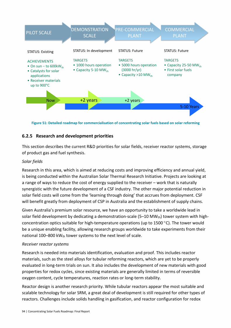
94 | Concentrating Solar Fuels Roadmap: Final Report
Figure 51: Detailed roadmap for commercialisation of concentrating solar fuels based on solar reforming
6.2.5 Research and development priorities
This section describes the current R&D priorities for solar fields, receiver reactor systems, storage
of product gas and fuel synthesis.
Solar fields
Research in this area, which is aimed at reducing costs and improving efficiency and annual yield,
is being conducted within the Australian Solar Thermal Research Initiative. Projects are looking at
a range of ways to reduce the cost of energy supplied to the receiver – work that is naturally
synergistic with the future development of a CSF industry. The other major potential reduction in
solar field costs will come from the ‘learning through doing’ that accrues from deployment. CSF
will benefit greatly from deployment of CSP in Australia and the establishment of supply chains.
Given Australia’s premium solar resource, we have an opportunity to take a worldwide lead in
solar field development by dedicating a demonstration-scale (5–10 MWth) tower system with high-
concentration optics suitable for high-temperature operations (up to 1500 C). The tower would
be a unique enabling facility, allowing research groups worldwide to take experiments from their
national 100–800 kWth tower systems to the next level of scale.
Receiver reactor systems
Research is needed into materials identification, evaluation and proof. This includes reactor
materials, such as the steel alloys for tubular reforming reactors, which are yet to be properly
evaluated in long-term trials on sun. It also includes the development of new materials with good
properties for redox cycles, since existing materials are generally limited in terms of reversible
oxygen content, cycle temperatures, reaction rates or long-term stability.
Reactor design is another research priority. While tubular reactors appear the most suitable and
scalable technology for solar SRM, a great deal of development is still required for other types of
reactors. Challenges include solids handling in gasification, and reactor configuration for redox
PILOT SCALE DEMONSTRATION
SCALEPRE-COMMERCIAL
PLANTCOMMERCIAL
PLANT
STATUS: Existing
ACHIEVEMENTS• On sun – to 600kWth
• Catalysts for solar applications
• Receiver materials up to 900°C
STATUS: In development
TARGETS• 1000 hours operation • Capacity 5-10 MWth
STATUS: Future
TARGETS• 5000 hours operation
(3000 hr/yr)• Capacity >10 MWth
STATUS: Future
TARGETS• Capacity 25-50 MWth
• First solar fuels company
5-10 Years
+2 years+2 yearsNow
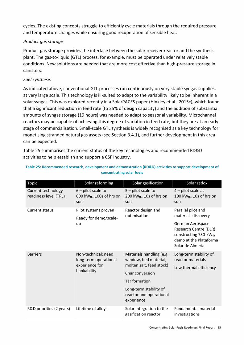
Concentrating Solar Fuels Roadmap: Final Report | 95
cycles. The existing concepts struggle to efficiently cycle materials through the required pressure
and temperature changes while ensuring good recuperation of sensible heat.
Product gas storage
Product gas storage provides the interface between the solar receiver reactor and the synthesis
plant. The gas-to-liquid (GTL) process, for example, must be operated under relatively stable
conditions. New solutions are needed that are more cost effective than high-pressure storage in
canisters.
Fuel synthesis
As indicated above, conventional GTL processes run continuously on very stable syngas supplies,
at very large scale. This technology is ill-suited to adapt to the variability likely to be inherent in a
solar syngas. This was explored recently in a SolarPACES paper (Hinkley et al., 2015c), which found
that a significant reduction in feed rate (to 25% of design capacity) and the addition of substantial
amounts of syngas storage (19 hours) was needed to adapt to seasonal variability. Microchannel
reactors may be capable of achieving this degree of variation in feed rate, but they are at an early
stage of commercialisation. Small-scale GTL synthesis is widely recognised as a key technology for
monetising stranded natural gas assets (see Section 3.4.1), and further development in this area
can be expected.
Table 25 summarises the current status of the key technologies and recommended RD&D
activities to help establish and support a CSF industry.
Table 25: Recommended research, development and demonstration (RD&D) activities to support development of
concentrating solar fuels
Topic Solar reforming Solar gasification Solar redox
Current technology readiness level (TRL)
6 – pilot scale to 600 kWth, 100s of hrs on sun
5 – pilot scale to 200 kWth, 10s of hrs on sun
4 – pilot scale at 100 kWth, 10s of hrs on sun
Current status Pilot systems proven
Ready for demo/scale-up
Reactor design and optimisation
Parallel pilot and materials discovery
German Aerospace Research Centre (DLR) constructing 750-kWth demo at the Plataforma Solar de Almeria
Barriers Non-technical: need long-term operational experience for bankability
Materials handling (e.g. window, bed material, molten salt, feed stock)
Char conversion
Tar formation
Long-term stability of reactor and operational experience
Long-term stability of reactor materials
Low thermal efficiency
R&D priorities (2 years) Lifetime of alloys Solar integration to the gasification reactor
Fundamental material investigations
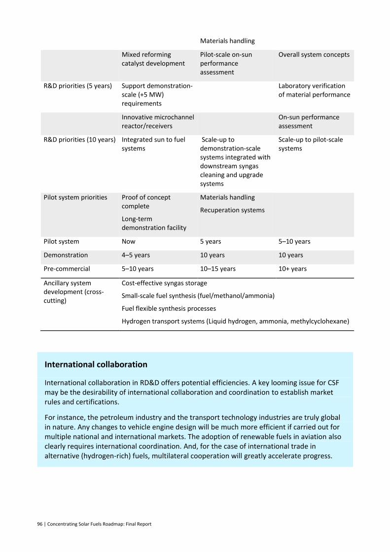
96 | Concentrating Solar Fuels Roadmap: Final Report
Materials handling
Mixed reforming catalyst development
Pilot-scale on-sun performance assessment
Overall system concepts
R&D priorities (5 years) Support demonstration-scale (+5 MW) requirements
Laboratory verification of material performance
Innovative microchannel reactor/receivers
On-sun performance assessment
R&D priorities (10 years) Integrated sun to fuel systems
Scale-up to demonstration-scale systems integrated with downstream syngas cleaning and upgrade systems
Scale-up to pilot-scale systems
Pilot system priorities Proof of concept complete
Long-term demonstration facility
Materials handling
Recuperation systems
Pilot system Now 5 years 5–10 years
Demonstration 4–5 years 10 years 10 years
Pre-commercial 5–10 years 10–15 years 10+ years
Ancillary system development (cross-cutting)
Cost-effective syngas storage
Small-scale fuel synthesis (fuel/methanol/ammonia)
Fuel flexible synthesis processes
Hydrogen transport systems (Liquid hydrogen, ammonia, methylcyclohexane)
International collaboration
International collaboration in RD&D offers potential efficiencies. A key looming issue for CSF may be the desirability of international collaboration and coordination to establish market rules and certifications.
For instance, the petroleum industry and the transport technology industries are truly global in nature. Any changes to vehicle engine design will be much more efficient if carried out for multiple national and international markets. The adoption of renewable fuels in aviation also clearly requires international coordination. And, for the case of international trade in alternative (hydrogen-rich) fuels, multilateral cooperation will greatly accelerate progress.
Concentrating Solar Fuels Roadmap: Final Report | 97
6.3 Societal acceptance
While solar energy in the form of PV has been enthusiastically adopted by the Australian
community, significant challenges remain for the commercialisation of CSF. Some of these issues
are discussed below.
Society now generally recognises that global warming is occurring and that we must make
structural changes and decarbonise our energy supply. The acceptance of more sustainable fuels
for this process will be critical. There has been a considerable backlash to the use of ethanol in
gasoline, rightly or wrongly. To avoid the same fate, any CSF product needs to be appropriately
verified to ensure it meets the necessary quality standards. Risks associated with ‘new fuels’ are
regarded much more critically than existing fuels, so the regulatory and approvals process will
need to be carefully managed. Synthetic diesel or gasoline is therefore likely to be considerably
easier to deploy than any truly novel fuel, since it has essentially the same composition as existing
fuels. It is also unclear whether consumers will be prepared to pay a premium for using a more
sustainable fuel option.
In the stakeholder workshop held in Sydney as part of this project, participants expressed some
concern over the public acceptance of new projects based on coal. Coal is undeniably the cheapest
feedstock in terms of $/GJ, and remains abundant. However, coal gasification technologies are less
well developed than natural gas reforming technologies.
Solar reforming of natural gas is the most readily deployed CSF technology, but still provides only a
partial reduction in carbon emissions: around 30%. The question in this case is whether this is
significant enough to contribute to global emissions reduction.
The uncertainty regarding the environmental and social sustainability of biofuels is a key non-
economic barrier to their use. Introducing a solar component to produce solar/biomass hybrid
fuels would help the case for sustainability overall. In contrast, a solar/fossil hybrid approach will
face major issues of social acceptability regarding its sustainability credentials.
For example, a benefit of solar/biomass hybrids is their potential to significantly increase biofuel
yield while decrease their impact on land use. The IEA Biofuels roadmap suggests that by 2050,
biofuels could provide 37% of total global demand for transport fuel: and in particular, target
replacement of diesel kerosene and jet fuel (IEA, 2011). But this target has major implications for
land use, with the 65 exajoules (EJ) of biofuel feedstock needed per year estimated to require
around 100 million hectares of land area in 2050. The 65 EJ for transport would be in addition to a
projected 80 EJ of biomass for future heat and power processes, competing further with
production of food and fibre. Overall, the roadmap suggests that all these demands could be met
in a sustainable manner. The combination of carbon capture and storage with biomass energy
sources offers the possibility of negative emissions systems. Adding a solar component to such a
configuration would increase the overall benefit.
6.4 Market development
As noted in Section 3, we have defined market development as the identification of suitable
products, and the development of the necessary infrastructure to deliver these products to
consumers. In some ways, market development is therefore the technology push in terms of fit to
98 | Concentrating Solar Fuels Roadmap: Final Report
the market, whereas customer demand includes aspects of the market that can be manipulated to
provide the market pull.
6.4.1 The challenge of low oil prices
Since 2014, the oil price has dropped significantly – and to many observers, unexpectedly. A low
oil price without any significant measures to reduce GHG emissions naturally reduces the incentive
to develop alternatives. But as yet, it is unclear whether the current situation is a short-term
anomaly or a trend to low oil prices in the long term.
Oil price projections are widely variable, ranging from as low as $60/bbl to $200/bbl in 2030
(Figure 17). With such low prices, demand for oil should increase, which will lead to the eventual
rebalance of supply and demand. When this happens, the oil price is expected to move upwards to
prices seen in more recent years. Under high demand, investment in new, more expensive sources
of oil will be required, which will thus increase the price of oil over $80/bbl.
Historically, the price of oil has always shown major fluctuations around an underlying increasing
trend, and that seems likely to continue. Given that oil prices could rise again within much shorter
time frames than the development trajectory of alternative fuels, it is important that effort is not
delayed by the current low prices. Added to this is the uncertain, but likely, observation that the
intended strong efforts to limit global warming to less than 2 C must by definition create a CO2-
emissions cost – either direct or indirect – for fossil fuels.
6.4.2 Most prospective markets
In Sections 3 and 5, the most promising potential markets for CSF were identified as follows:
export of hydrogen (or ammonia as a hydrogen carrier) to Japan and South Korea
export of methanol as a globally traded commodity to China
domestic production of ammonia as a commodity chemical
domestic production of diesel or gasoline as a substitute transport fuel in Australia
domestic production of methanol for blending with gasoline.
Overall, while the uncertainty around the global energy future does make major investment
decisions more difficult, we can also argue that a major initiative in solar and other renewable
fuels is an effective way of insuring against such uncertainty.
For the users of transport fuel in Australia, exchange rates, refining and distribution costs are all
important factors that dilute the effect of crude oil price fluctuations. This suggests that a CSF
strategy that can directly produce a usable transport fuel is preferable to a strategy that produces
a crude oil substitute.
Looking at the Asian export markets, continued demand growth for some form of transport fuel,
plus a trend to reducing emissions, seems fairly certain. Once again, a solar fuel that is in a direct
end-use form, rather than a form that competes with the most volatile international crude oil or
gas markets, seems the wisest.
Concentrating Solar Fuels Roadmap: Final Report | 99
From the point of view of a roadmap to commercial maturity, a parallel argument suggests that
producing a product with an immediate market as a chemical commodity could be a good
strategy. In this regard, the following points are pertinent:
Large-scale ‘conventional’ Fischer–Tropsch plants have the disadvantage of very large sizes
needed for economic operation with consequent high investment needs; the fuel they
produce also requires considerable post-processing.
Methanol plants are smaller and more modular, and methanol has an existing international
market. It can be added directly to gasoline at low percentages, even if it cannot substitute
directly without technical modifications.
Microchannel Fischer–Tropsch reactors potentially offer lower cost and higher modularity
than large systems, and may be able to be customised to directly produce a drop-in
gasoline or diesel substitute. These are still in the R&D phase, but could be commercial
within the same timescale as overall solar-driven systems.
Ammonia is also an internationally traded commodity and is already produced at multiple
sites in Australia. While it does not offer a direct entry to the Australian transport market,
it could prove to be a good vector for international energy exports.
6.5 Customer demand
Customer demand refers to the desire of consumers and stakeholders, including government and
regulatory bodies, for CSF products. The drivers for different stakeholders will vary significantly.
From a state and federal government perspective, a likely key driver is emissions reduction.
However, when consumers have to decide between different products, cost is the dominant
factor. This section discusses policy measures that can help meet the needs of all stakeholders by
establishing the market pull that will lead to the commercialisation of CSF technologies.
Two main types of barriers need to be addressed:
– cost barriers, where CSF are more expensive (or at least not substantially cheaper) than
their conventional fossil competitors
– legislative barriers, such as fuel standards.
6.5.1 Options for developing markets with a cost gap
Our analysis suggests that once the technology is established and deployed at reasonable scale,
CSF can be produced for about the same price as conventional fossil derived alternatives. The first
plants constructed will naturally face a far tougher challenge, due to the higher costs of ‘first-of-a-
kind’ and early-stage commercial projects. As the technology matures, the cost of CSF is expected
to decrease, while the price of conventional fuels is expected to slowly increase in real terms.
Support mechanisms must therefore be put in place to support the construction of early-phase
projects, and to ensure that the market dynamics can provide a long-term return for subsequent
corporate investors. Early-stage projects can be initiated with grant funding, while the ongoing
viability of the industry will require some form of support that can gradually decrease.
100 | Concentrating Solar Fuels Roadmap: Final Report
Typically, Australian governments favour technology-neutral market mechanisms. Experience
gained from other industries, such as biofuels and renewable energy, can help shape effective
policies that support a CSF industry. Examples of such policies are discussed below.
Removing fossil fuel subsidies
Fossil fuel subsidies are a contentious issue, with debated topics including what constitutes a
‘subsidy’ vs a ‘tax rebate on business input’. In any case, the policy measures in place that help the
fossil fuel industry do not advance the cause for moving to renewable alternatives.
One case often raised is the diesel excise rebate for mining or primary producers. We could argue
that fuel excise of any kind might best be replaced by a price on carbon, and that if a particular
industry sector is deserving support, it should not be via a mechanism that implicitly encourages
fossil fuel use.
Blending mandates
Blending mandates or targets for biofuels are a suitable measure to drive production and have
already been adopted in 50 countries. Biofuel mandates and targets represent a good precedent
for CSF, and such measures could be generalised to cover fuels from any renewable resource.
A more challenging philosophical discussion would be needed to argue that such mandates be
extended to solar/fossil hybrid fuels. Arguably, extension of such a fuel mandate could be
accompanied by a GHG penalty applied specifically to qualifying ‘new’ fuels. This would also send
useful market signals regarding sustainability to the biofuels sector, since some biofuel production
systems use much more fossil fuel than others. Queensland has recently introduced a biofuels
mandate and New South Wales is currently considering their options.
Carbon pricing
When this roadmap project began, the price of oil was in excess of $100/bbl and Australia had a
price on carbon. Subsequently, the price of oil has halved, Australia no longer has a price on
carbon and the Australian dollar has fallen considerably against the United States dollar. Current
indications are that global initiatives on reducing carbon emissions are likely to strengthen, even if
the policies in any individual country are subject to sudden changes.
If Australia moves to strengthen its efforts in line with international trends, some form of carbon
pricing needs to emerge. This should provide a major boost for lower-emission fuels. However,
note that under the previous carbon-pricing legislation, transport fuels were exempt, which was
an unfortunately perverse outcome of the political process.
Building on the Renewable Energy Target
The Australian Renewable Energy Target currently addresses renewable electricity production. It is
similar to many such ‘renewable energy portfolio’ standards around the world. A state blending
mandate is, in a sense, also a location and technology-specific renewable purchase obligation. The
Renewable Energy Target has worked well for electricity, and could readily be duplicated to create
a parallel ‘Renewable Fuels Target’ (or Zero-Emission Fuels Target), using the same basic legislative
and administrative approach.
Such a national target could be fuel, technology and end-use neutral. Arguably, if implemented in
a consultative manner, it could replace ad hoc, state-based biofuels mandates. The currently
Concentrating Solar Fuels Roadmap: Final Report | 101
available biofuels would likely be the first to benefit, but the target would provide a market that
CSF could then progressively enter. Target certificates could be earned for any fuel product
entering an existing retail supply chain. Therefore, blending fuels, drop-in fuels, or addition of gas
to natural gas networks could all earn certificates on an energy content basis.
Feed-in tariffs
Feed-in tariffs have played a major role in the emergence of PV technology worldwide. A
predetermined tariff for sale of energy into the ‘traditional’ marketplace gives great certainty to
investors in new technology. And, when sufficiently high, the tariff drives very rapid deployment.
This concept could equally be applied to fuels. One criticism is that overly generous tariffs
represent a greater than necessary impost on the economy, and don’t sufficiently encourage cost
reduction. A reverse auction process to establish a tariff could address this.
Contracts for difference
The Australian Capital Territory government has used a process of reverse auctions for ‘contract
for difference’ tariffs to drive supply outcomes for itself. Such a contract is designed to provide
overall tariff certainty by covering the gap between the agreed tariff cap and the variable income
obtained for existing market processes.
Direct subsidies
Grants offered by organisations such as the Australian Renewable Energy Agency (ARENA) can
clearly drive deployment up to the budget limit of the organisation. They are very effective for
early-stage technologies; however, tax payer funds are not likely to be the best means of support
once an industry has grown beyond a certain size.
Low-cost finance
Loan guarantees and low-interest finance – or even finance provided without technology risk
penalties – reduce risk for project developers with high capital cost projects. This is a role that the
Clean Energy Finance Corporation (CEFC) already usefully fills in Australia.
Tax benefits
In the United States in particular, renewable energy technologies have been supported via the tax
system. Income tax credits are production-based credits that act very much like a feed-in tariff.
Accelerated depreciation schemes assist with high capital costs and encourage corporations with
high tax liabilities to engage with new technologies.
6.5.2 Addressing non-economic barriers
The lack of overall infrastructure for a new fuel is a large barrier to some CSF options. This is very
fuel-specific, and must form a major consideration in setting solar fuels strategies. A fully fungible
drop-in fuel, such as a Fischer–Tropsch diesel product, clearly suffers no impediment other than
the primary production infrastructure. At the other extreme, switching to a pure hydrogen-based
transport system has major infrastructure implications, and represents an important factor in
choosing whether such a route is desirable.

102 | Concentrating Solar Fuels Roadmap: Final Report
For other fuels, some factors allow early introduction to be relatively easy, but production then
reaches a bottleneck. For example, the biofuels roadmap refers to the ‘blending wall’ for ethanol,
which is the 10–15% limit on blending in gasoline for unmodified engines (IEA, 2011). Tax
incentives to encourage ‘flexible fuel vehicles’ are suggested in the roadmap as a possible
response.
Much of the strategic analysis in the Australian hydrogen roadmap provides useful input to the
consideration of CSF (Wyld Group, 2008). The barriers identified – and in some cases, also relevant
to CSF – are categorised as regulatory, public, cost, technical, market entry, policy and programs.
Regulatory barriers deserve particular mention in the context of CSF. In this roadmap, we have not
attempted to examine the relevant regulations in any manner. However, the long history of
engagement with oil and gas, gas transmission and distribution, supply and retail of gasoline, and
diesel and chemical commodities production, reveals a detailed set of regulations specific to each
application. This is in addition to planning requirements for project construction in general. None
of this historic base of regulation has anticipated the new aspects associated with CSF and
renewable fuels in general. A thorough audit of these aspects would therefore be extremely
valuable.
6.5.3 A vision for deployment
Our study has found that CSF represents a very attractive opportunity for Australia. As an industry,
we suggest that CSF should be seen as an extension of a concentrating solar industry that is
currently focused on power generation. We feel it is of great interest to ask what could realistically
be achieved in terms of deployment, if all necessary policy measures and market signals were put
in place.
By the end of 2016, if the Kogan Creek Solar Boost project in south-west Queensland2 is
completed, Australia would have approximately 140 MWth of installed solar field capacity. Since
2006, the global CSP industry has sustained compound growth rates between 30 and 40% per
year; therefore, growth rates of that magnitude are clearly technically feasible.
If Australian CSP growth were to continue from 2016 onwards at 30% per year, and CSF capacity
were to begin with a first commercial installation of 50 MWth in 2020 and then grow at a slightly
faster rate of 35% per year, the resulting deployment trajectory would be as shown in Figure 52
and Figure 53 (note the differing time scales).
2 http://kogansolarboost.com.au/

Concentrating Solar Fuels Roadmap: Final Report | 103
Figure 52: Potential deployment of concentrating solar thermal (CST) technologies for power and fuel to 2030 Note: CSF = concentrating solar fuels; CSP = concentrating solar power
Figure 53: Potential deployment of concentrating solar thermal (CST) technologies for power and fuel to 2050 Note: CSF = concentrating solar fuels; CSP = concentrating solar power
The figures show that CSP begins to make a noticeable contribution to Australia’s electricity
demand by 2030 and then subsequently levels off at around 20% of electricity demand by 2050. By
2030, CSF systems would be providing substantial input to the national economy and by 2050, CSF
systems would overtake CSP as the driver for CST deployment.
6.6 Actions needed from stakeholders
The discussion above leads to this roadmap’s following general recommendations:
– CSF R&D should be a priority, and should target
reactor lifetimes
104 | Concentrating Solar Fuels Roadmap: Final Report
recuperation of heat from reactants to maximise efficiency
low-cost underground storage of hydrogen/syngas mixtures.
– State mandates for biofuels could be generalised to include all renewable fuels.
– The Renewable Energy Target could be expanded or replicated to include renewable fuels.
– Fossil fuel subsidies (e.g. diesel excise rebates) should be removed and/or appropriate
carbon-pricing measures be considered.
– A pipeline of Australian CSP deployment is needed to build capability and supply chain
that can be leveraged for a future CSF industry.
– A regional test platform should be established at 5–10 MW scale for a range of CST
technologies, including a demonstration of solar steam methane reforming.
– Bilateral government negotiations with Japan and others could establish international
renewable fuels trade.
To build a progressive Australian CSF industry, a range of stakeholders could contribute to the
actions required. The key stakeholders are:
Australian federal government
ARENA and/or similar funding agencies
state governments
CST industry
petroleum and other industry
research organisations.
The general recommendations above lead to a range of more detailed, specific actions that each
of the key stakeholders could take. The various roadmaps and strategic studies in aligned fields
reviewed in Section 1.4 and referenced throughout this study offer valuable actions and
responses, which are in many cases directly relevant to CSF in Australia. The following suggested
actions (Table 26) include ideas that have been directly modified from these sources, as well as
those that have become apparent during this study.
Table 26: Recommended actions for various stakeholders to establish and grow a concentrating solar fuels (CSF)
industry in Australia
Stakeholder Action item
Australian federal government
Provide long-term targets and support polices that stimulate investments in sustainable renewable fuels production, and ensure that advanced renewable fuels such as CSF reach commercial production
Pursue bilateral agreements with Japan and others to establish trade in renewable/emission-free fuels
Establish a firm clear price mechanism for greenhouse gas (GHG) emissions
Progressively eliminate subsidies to fossil fuels
Concentrating Solar Fuels Roadmap: Final Report | 105
Implement sound sustainability criteria for advanced renewable fuels based on internationally agreed indicators
Set minimum GHG reduction targets and integrate the environmental and social performance of renewable fuels in national support schemes
Audit regulations and fuel standards and remove barriers to renewable fuel implementation
Develop international standards for new renewable fuels
Establish market rules for renewable gas injection to pipelines
Consider government procurement of renewable fuels for the Australian Department of Defence, as done in the United States, to provide pull through for CSF
Review the Renewable Energy Target and establish a similar or extended mechanism for a Renewable Fuels Target that mandates a growing fraction of renewable fuel use in overall end-use traded fuels
As future GHG policy and legislation emerges, ensure there are no negative perverse outcomes for renewable fuels such as exclusion of transport fuels
Link financial support schemes to the sustainability performance of the fuel; this could include a GHG emissions price subtracted from production incentives over and above any GHG emissions price in the wider community
Australian Renewable Energy Agency or similar funding agencies
Provide increased and sustained research, development and demonstration (RD&D) funding to promote cost and efficiency improvements for advanced renewable fuels such as CSF
When allocating R&D funding, ensure successful projects involve interdisciplinary teams spanning chemical engineering, mechanical engineering and economics
Continue and increase involvement in the International Energy Agency (IEA) SolarPACES, Hydrogen Implementing Agreement and Bioenergy programs, and United States Department of Energy Solar Thermochemical Hydrogen program, and encourage collaborative action among these activities
Support the construction of a first utility-scale CSP tower system in Australia
Support collaborative workshops e.g. Japan–Australia
Support the establishment of an Australia/Asia solar thermal test facility that prioritises pilot-scale demonstration of near-commercial CSF systems
State governments Review existing biofuels mandates and generalise to renewable fuel-blending mandates in all fuel commodities for domestic use to include CSF
Establish a one-stop shop for project approvals to streamline the currently protracted project development process
Establish large areas as solar precincts, pre-approved for large-scale solar projects
106 | Concentrating Solar Fuels Roadmap: Final Report
Concentrating solar thermal (CST) industry
Adopt CSF as part of long-term strategy for the growth of the concentrating solar industry
Demonstrate reduced costs for solar concentrator systems through continued deployment
Establish/strengthen an Australian CST industry association
Continue to lobby and educate governments on the sources of value offered by CST beyond that of variable renewable generation (e.g. grid stabilisation)
Petrochemical and other industries
Embrace advanced renewable fuels as part of a long-term vision for continuing the industry while progressively reducing GHG emissions
Directly engage with research organisation and share relevant data to facilitate R&D
Seek opportunities to deploy CST technologies in existing plants
Research organisations
Seek partnerships with established CSP or petrochemical industry players to pursue technology development in CSF with strong prospects for commercialisation
Demonstrate the full production chain in RD&D pilot projects to include a final fuel synthesis step and maximise outreach and educational value
Prioritise CSF R&D on areas where fundamental efficiencies, materials and component lifetimes will enable commercial viability
Establish national inventories of underground storage opportunities for renewable hydrogen and hydrogen containing gas mixes
The Australia–Asia Concentrating Solar Test Facility (AACSTF)
A key recommendation of the roadmap is the establishment of a demonstration-scale CSF facility. In the order of 5–10 MWth, the facility would encompass high-quality heliostats capable of operation at high solar concentration ratios suitable for a wide range of CSF receiver reactor systems.
The facility would also provide a location for private companies to build and test pilot systems in an area with supporting and shared infrastructure.
We suggest that this be a collaborative effort between Australia and Japan in the first instance, with possible involvement of other countries such as South Korea or China also under consideration.
While the receiver system should be interchangeable to suit a chosen technology, the solar field, downstream processing and fuel synthesis and clean-up could all be standardised to suit a wide range of reactors and products.
As worldwide research efforts lead to maturing CSF technologies, the facility would establish itself as the premium site for scale-up, attracting the world’s best research groups as well as industrial and commercial partners looking to become part of the next wave of solar technology. The facility could also include other CST technology demonstrations and act as a
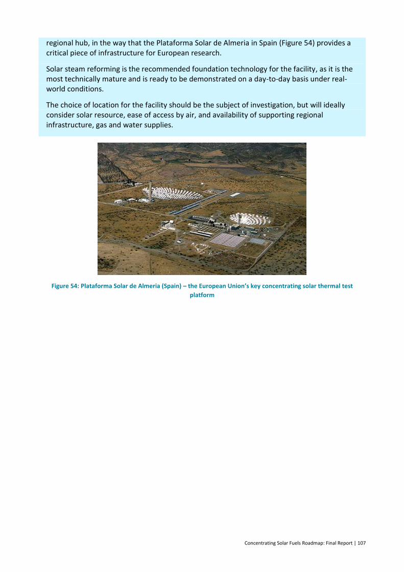
Concentrating Solar Fuels Roadmap: Final Report | 107
regional hub, in the way that the Plataforma Solar de Almeria in Spain (Figure 54) provides a critical piece of infrastructure for European research.
Solar steam reforming is the recommended foundation technology for the facility, as it is the most technically mature and is ready to be demonstrated on a day-to-day basis under real-world conditions.
The choice of location for the facility should be the subject of investigation, but will ideally consider solar resource, ease of access by air, and availability of supporting regional infrastructure, gas and water supplies.
Figure 54: Plataforma Solar de Almeria (Spain) – the European Union’s key concentrating solar thermal test
platform
108 | Concentrating Solar Fuels Roadmap: Final Report
7 Conclusions and recommendations
Oil provides approximately 30% of global primary energy and is the largest single contributor to
greenhouse gas (GHG) emissions. More significantly, trade in oil accounts for around 70% of the
financial turnover in the energy sector as a whole, reflecting the high value that follows from its
versatility, high energy density and key role in transport. To date, world efforts to expand
renewable energy contributions have largely been in the electricity sector, where rapid progress is
being made. However, if international efforts to limit global warming to below 2 C are to succeed,
then emission-free solutions to replace fossil oil and natural gas, particularly for transport, are
urgently needed.
Electrification of transport via passenger vehicles and trains will increase over time and contribute
to reduced emissions. However, the advantages of liquid fuels – high energy density storage, quick
refuelling and efficient distribution infrastructure – make their continued use attractive and
arguably essential for air travel and long-distance freight.
Options for producing liquid fuels in an emission-free manner include fossil fuels combined with
carbon capture and storage (CCS), biofuels, renewable-electricity-driven electrolysis, and
concentrating solar fuels (CSF).
This roadmap has examined the CSF options in detail. We conclude that hybrid options are
attractive in the medium term, while pure solar-driven thermochemical processes for water and
CO2-splitting appear promising in the long term.
CSF technologies will be deployed as a natural evolution of the growth and diversification of a
concentrating solar thermal (CST) sector, which is currently almost exclusively devoted to
concentrating solar power (CSP). CSP globally is growing strongly, with the same growth trajectory
as photovoltaics (PV), but about one decade behind. Growth in CSP will drive cost reductions in
solar field components, which will make CSF competitive as the new receiver technologies mature.
As part of this roadmap, we have carried out the most complete review of the published literature
on CSF to date. During our study, we reviewed 1322 publications, examining factors such as key
operating parameters, technology readiness level (TRL), and limits to conversion efficiencies. The
technologies reviewed range from hybrid solar plus gas, biomass or coal options, with TRLs in the
range 1 to 6, to advanced, multistep water-splitting processes with TRLs in the range 1 to 5.
The process of creating a CSF for market involves a primary solar-driven stage that produces either
pure hydrogen or a mixture of hydrogen, carbon monoxide and carbon dioxide (syngas). This is
followed secondary processes that produce saleable fuels. Many different solar-to-syngas and
syngas-to-fuel technologies are available. However, many are still in the demonstration or
research and development (R&D) phase, and thus require support become a commercial reality.
We have developed an innovative, comprehensive approach to evaluating the levelised cost of the
solar process gases, followed by the final synthesised CSF. This approach has been applied to an
extensive, generalised range of solar receiver reactor plus reaction system combinations. Aside
from the cost of feedstock, the key driver of cost effectiveness is the solar-to-chemical conversion
Concentrating Solar Fuels Roadmap: Final Report | 109
efficiency. Our calculation method uses key parameters of operating temperature and overall
mass-flow rates of species passing through the reactor system to evaluate ‘optimistic/realistic’
values that could be achieved from each receiver/reaction system combination. By doing this in a
consistent manner, a meaningful ranking of technologies was produced. The method clearly
demonstrated the importance of minimising thermodynamically unnecessary mass-flow streams
and maximising the recuperation of sensible heat.
We also conducted a systematic screening process that combines the solar levelised cost of fuel
with criteria that determine the relative prospects for commercialisation, such as the current TRL,
the difficulty of unsolved hurdles, and the GHG reduction potential.
The highest ranked process was steam reforming of natural gas. This was due to its good
economics ($10–15/GJ for solar syngas), current high TRL and relatively low score for unsolved
hurdles. Developing this technology to a higher TRL will require significant investment in a plant
that can operate on a more or less continuous basis, to build up the hours of operation needed to
make the process ‘bankable’.
Water splitting with redox cycles also scored well in the screening. Despite its much higher syngas
production cost (~$30/GJ), it has a reasonable TRL score, having been demonstrated at 100 kWth
scale; a significant amount of international R&D; and most importantly, zero GHG emissions.
Coal and biomass gasification scored slightly lower than water splitting, due to higher GHG
intensity (CCS was not considered), lower R&D effort, and a higher score on the unsolved hurdles
associated with the difficulty of handling solid material instead of gas. However, brown coal did
have a low syngas production cost (~$3.5/GJ), due to its low feedstock cost.
Gasification technologies and redox cycles require more work at the laboratory and pilot
demonstration scale before they can be built at the pre-commercial demonstration plant scale.
However, continued development in these technologies is possible, in parallel with demonstration
of natural gas reforming at a larger scale. Parallel development of various promising options at
different scales moves all of them progressively along the TRL scale towards commercial
realisation.
The key potential markets for solar fuels are offsetting oil imports for transport fuel in Australia,
and export opportunities to Japan, China and Korea. In Australia, net oil imports are one of the
most significant import costs for the country. This cost is growing rapidly as a result of declining
domestic production and growing demand, together with what was an upward trend to
international oil prices and will likely be so again in future decades.
Australia has ample solar, coal and biomass resources to produce pure solar fuels and/or solar
hybrid fuels. The transport costs of final fuel products to international markets are more than
justified by our superior resources.
Japan is Australia’s most important trading partner for energy, and is the largest destination for
the coal and LNG exports that are a major share of Australia’s export income. Because Japan is
dependent on imported energy, it is actively looking to diversify, improve efficiency, reduce its
dependence on Middle East oil and reduce its GHG emissions. It is also actively promoting a
hydrogen economy and developing supply chains for renewable hydrogen. Japan has no significant
solar resource compared with Australia’s world-leading position. Together, these factors make it
an ideal target market for our solar fuels.

110 | Concentrating Solar Fuels Roadmap: Final Report
Ammonia and methanol are two key chemical commodities already traded globally, which may in
future grow to become major fuel vectors. The projected costs for ammonia and methanol
production based on solar-driven reforming suggest that a solar-derived product could be
competitive by 2020, even before consideration of GHG costs.
Domestically, near-term markets could be created with suitable government action via blending.
Additions of 20% methanol to gasoline, blending of dimethyl ether (DME) with liquefied petroleum
gas (LPG) and additions of up to 20% hydrogen to natural gas can all be contemplated without
vehicle and end-use infrastructure changes. We expect that this blending approach would
gradually evolve and that eventually, new emission-free standard fuels may completely replace
diesel and gasoline.
We have also examined the challenges and solutions to implementation of a CSF industry in
Australia, considering technology development, societal acceptance, market development and
customer demand. From this, we have developed a detailed list of R&D priorities. The successful
establishment of an Australian CSF industry would be aided by suitable actions across stakeholder
groups including research organisations, state and federal governments, funding agencies and
industrial players.
The list of suggested actions for each stakeholder group can be broadly summarised as:
– CSF R&D should be a priority, and should target
parallel development of multiple technology options to enable a staged approach
to reducing carbon intensity
materials discovery for redox metal oxide systems
reactor design and development for gasification based processes
reactor lifetimes
recuperation of heat from reactants to maximise efficiency
full CSF production evaluation to final products
low-cost underground storage of hydrogen/syngas mixtures
high temperature storage and heat transfer fluids.
– State mandates for biofuels could be generalised to include all renewable fuels.
– The Renewable Energy Target could be expanded or replicated to include renewable fuels.
– Fossil fuel subsidies (e.g. diesel excise rebates) should be removed and/or appropriate
carbon-pricing measures be considered.
– A pipeline of Australian CSP deployment is needed to build capability and supply chain
that can be leveraged for a future CSF industry.
– A regional test platform should be established at 5–10 MWth scale for a range of CST
technologies, including a demonstration of solar steam methane reforming.
– Bilateral government negotiations with Japan and others could establish international
renewable fuels trade.
Our cost analysis suggests that CSF approaches to pure solar hydrogen production are likely to be
less than half the cost of PV plus electrolysis. Competitiveness against advanced biofuels options
will depend on the cost of available biomass; as there is only a limited supply potential for cheap

Concentrating Solar Fuels Roadmap: Final Report | 111
biomass, both approaches have a role. Competiveness against fossil fuels plus CCS is difficult to
determine at this stage. Overall, we suggest that major policy initiatives should be made in a
technology-neutral manner, such that all approaches can compete in new zero-emission fuel
markets.
With suitable strategic initiatives in these directions, an Australian CSF industry established over
the next two decades could grow to be of equal or larger value to the economy than today’s fossil
fuel industry.
112 | Concentrating Solar Fuels Roadmap: Final Report
References
Aasberg-Petersen, K., Nielsen, C. S., Dybkjaer, I. & Perregaard, J. 2013. Large scale methanol production from natural gas, Haldor Topsoe
Abanades, S., Charvin, P., Flamant, G. & Neveu, P. 2006. Screening of water-splitting
thermochemical cycles potentially attractive for hydrogen production by concentrated solar energy. Energy, 31: pp 2805-2822.
Abanades, S. & Flamant, G. 2006. Solar hydrogen production from the thermal splitting of
methane in a high temperature solar chemical reator. Solar Energy, 80: pp 1321-1332.
ACIL Tasman and Parsons Brinckerhoff. 2003. National Hydrogen Study,
(http://www.industry.gov.au/Energy/Documents/national_hydro_study.pdf).
AECOM. 2013. Australian Remote Renewables: Opportunities for Investment, (Canberra).
Agrafiotis, C., von Storch, H., Roeb, M. & Sattler, C. 2014. Solar thermal reforming of methane
feedstocks for hydrogen and syngas production - a review. Renewable & Sustainable Energy Reviews, 29: pp 656-682.
American Methanol Institute. 1991. Methanol Fact Sheets, Available online at:
http://www.afdc.energy.gov/pdfs/2475.pdf
Apodaca, L. E. 2015. Nitrogen (fixed) - ammonia,
(minerals.usgs.gov/minerals/pubs/commodity/nitrogen/mcs-2015-nitro.pdf).
APPEA. 2014. LNG export markets. Available at: http://www.appea.com.au/oil-gas-
explained/benefits/benefits-of-lng/export-revenue/ [Online].
Apt, J., Newcomer, A., Lave, L. B., Douglas, S. & Dunn, L. M. 2008. An engineering economic
analysis of syngas storage, National Energy Technology Laboratory, U.
autoblog. 2015. Japanese automakers will seriously subsidize hydrogen fuel stations [Online].
http://www.autoblog.com/2015/07/01/japanese-automakers-will-seriously-subsidize-hydrogen-fuel-stati/. [Accessed 26 October 2015].
Benito, R., Duffy, G. J., Do, K. T., McNaughton, R., Edwards, J. H., Dave, N., Chensee, M. & Walters,
C. 2003. Csiro's advanced power generation technology using solar thermal - Fossil energy hybrid systems. Greenhouse Gas Control Technologies, Vols I and Ii, Proceedings: pp 1813-1816.
Concentrating Solar Fuels Roadmap: Final Report | 113
Bertuccioli, L., Chan, A., Hart, D., Lehner, F., Madden, B. & Standen, E. 2014. Study on
development of water electrolysis in the EU, E4tech Sàrl with Element Energy Ltd for the Fuel Cells and Hydrogen Joint Undertaking
BREE. 2013. Australian Energy Technology Assessment 2013 Model Update, (Canberra).
BREE. 2014. Energy in Australia, (Canberra).
BREE. 2015. Australian energy statistics data., (Canberra).
Buckley, T. 2014. India's plan to stop importing coal deals another blow to Australia. Available at:
http://reneweconomy.com.au/2014/indias-plan-stop-importing-coal-deals-another-blow-australia-68894 [Online]. RenewEconomy. [Accessed 13 November 2014].
Chambers, M. 2014. Gladstone pays high price for its new industry. The Australian, 25 January.
Chueh, W., Falter, C., Abbot, A., Scipio, D., Furler, P., Haile, S. & Steinfeld, A. 2010. High flux solar-
driven thermochemical dissociation of carbon dioxide and water using non-stoichiometric ceria. Science, 330: pp 1797 - 1801.
Chueh, W. & Haile, S. 2010. A thermochemical study of ceria: Exploiting an old material for new
modes of energy conversion and carbon dioxide mitigation. Philosophical Transactions of the Royal Society a-Mathematical Physical and Engineering Sciences, 368 (1923): pp 3269 - 3294.
Chueh, W. C. & Haile, S. M. 2009. Ceria as a Thermochemical Reaction Medium for Selectively
Generating Syngas or Methane from H2O and CO2. Chemsuschem, 2 (8): pp 735-739.
City Climate Leadership Awards. 2014. Seoul: Hydrogen Fuel Cells. Available at:
http://cityclimateleadershipawards.com/seoul-hydrogen-fuel-cells/ [Online].
ClimateWorks_Australia, ANU, CSIRO & CoPS. 2014. Pathways to deep decarbonisation in Australia
in 2050: How Australia can prosper in a low carbon world: Technical Report, (Melbourne, Victoria).
CO2CRC. 2015. Australian Power Generation Technology Report,
(http://www.co2crc.com.au/dls/Reports/LCOE_Report_final_web.pdf).
Core Energy Group. 2013. Projections of gas demand for LNG export from Eastern and South
Eastern Australia, Core Energy Group, Available online from http://www.aemo.com.au
114 | Concentrating Solar Fuels Roadmap: Final Report
Crawford, D. F., O'Connor, M. H., Jovanovic, T., Herr, A., Raison, R. J., O'Connell, D. A. & Baynes, T. 2014. The spatial assessment of biomass for bioenergy in Australia in 2010, and potential expansion by 2030 and 2050 (In review). Global Change Biology Bioenergy: pp.
CSIRO. 2008. Fuel for thought: The future of transport fuels: challenges and opportunities.
Available at: http://www.csiro.au/files/files/plm4.pdf, (Canberra).
CSIRO. 2011a. Flight path to sustainable aviation: towards establishing a sustainable aviation fuels
industry in Australia and New Zealand, (CSIRO).
CSIRO. 2011b. Flight path to sustainable aviation: towards establishing a sustainable aviation fuels
industry in Australia and New Zealand., (Canberra).
Department of Foreign Affairs and Trade. 2012. Australia's top 25 imports, goods and services.
Available at: http://dfat.gov.au/publications/tgs/CY2012-goods-services-top-25-imports.pdf,
Department of Foreign Affairs and Trade. 2014. Republic of Korea country brief. Available at:
http://www.dfat.gov.au/geo/rok/brief_index.html,
Diver, R. B., Miller, J. E., Siegel, N. P. & Moss, T. A. 2010. Testing of a Cr5 Solar Thermochemical
Heat Engine Prototype. Es2010: Proceedings of Asme 4th International Conference on Energy Sustainability, Vol 2: pp 97-104.
Dolan, M. D., Hla, S., Beath, A., Fogliaresi, M., Langley, M., Soo Too, Y., Kochanek, M., Viano, D.,
Grigore, M., Morpeth, L., Edwards, J., Duffy, G., Hinkley, J., McNaughton, R., Morgan, S., Smith, M., Weir, S., Rae, M., Dawson, A., Way, J. D. & Abu El Hawa, H. 2015. Solar hybrid fuels: stream 2, (CSIRO).
Ermanoski, I., Miller, J. E. & Allendorf, M. D. 2014. Efficiency maximization in solar-thermochemical
fuel production: challenging the concept ofisothermal water splitting. Physical Chemistry, 16: pp 8418-8427.
Ewan, B., Graf, D., Monnerie, N., Sattler, C., le Naour, F., Stein, W. & Hinkley, J. 2007. INNOHYP CA
- Final Report, (Grenoble, France).
Faberi, S., Paolucci, L., Velte, D. & Jiménez, I. 2014. Methanol: a future transport fuel based on
hydrogen and carbon dioxide? Economic viability and policy options, (Brussels, EU).
Ferioli, F., Schoots, K. & van der Zwaan, B. C. C. 2009. Use and limitations of learning curves for
energy technology policy: A component-learning hypothesis. Energy Policy, 37 (7): pp 2525-2535.
Concentrating Solar Fuels Roadmap: Final Report | 115
Giaconia, A., de Falco, M., Caputo, G., Grena, R. & Tarquini, P. 2008. Solar steam reforming of natural gas for hydrogen production using molten salt heat carriers. Aiche Journal, 54 (7): pp 1932-1944.
Global CCS Institute. 2014. CCS Roadmap for Industry: High-purity CO2 sources,
(http://hub.globalccsinstitute.com/publications/ccs-roadmap-industry-high-purity-co2-sources-sectoral-assessment-%E2%80%93-final-draft-report/1).
Gokon, N., Yamamoto, H., Kondo, N. & Kaodama, T. 2010. Internally circulating fluidized bed
reactor using m-ZrO2 supported NiFeO4 Particles for thermaochemical two-Step Water Splitting. Journal of Solar Energy Engineering, 132 (May): pp 021102 - 1 - 10.
Gonzalez, R. S. & Flamant, G. 2014. Technical and Economic Feasibility Analysis of Using
Concentrated Solar Thermal Technology in the Cement Production Process: Hybrid Approach-A Case Study. Journal of Solar Energy Engineering-Transactions of the Asme, 136 (2): pp.
Government of Japan. 2014. Strategic Energy Plan, (Japan).
Graf, D., Monnerie, N., Roeb, M., Schmitz, M. & Sattler, C. 2008. Economic comparison of solar
hydrogen generation by means of thermochemical cycles and electrolysis. International Journal of Hydrogen Energy, 33: pp 4511-4519.
Graham, P., Reedman, L., Brinsmead, T., Hayward, J. & Ferraro, S. 2015. Future Grid Forum – 2015
Refresh: Technical report., CSIRO report for the Energy Networks Association Australia
Graham, P. W. & Reedman, L. J. 2015. Transport Greenhouse Gas Emissions Projections 2014-
2050: Supplementary results for revised oil prices,
Grübler, A., Nakicenovic, N. & Victor, D. G. 1999. Dynamics of energy technologies and global
change. Energy Policy, 27 (5): pp 247-280.
Haas, R. 2002. Market deployment strategies for PV systems in the built environment – An
evaluation of incentives, support programmes and marketing activities, Report IEA PVPS T7-06: 2002, International Energy Agency Implementing Agreement on Photovoltaic Power Systems (IEA PVP)
Hansen, J. B. & Nielsen, P. E. H. 2008. Methanol synthesis. In: Ertl, G., Knozinger, H., Schuth, F. &
Weitkamp, J. (eds.) Handbook of Heterogeneous Catalysis, Second Edition. Wiley-VCH Verlag GmbH and Co. KGaA, Weinheim.
Hayward, J. A., O'Connell, D. A., Raison, R. J., Warden, A. C., O'Connor, M. H., Murphy, H. T., Booth,
T. H., Braid, A. L., Crawford, D. F., Herr, A., Jovanovic, T., Poole, M. L., Prestwidge, D., Raisbeck-Brown, N. & Rye, L. 2015. The economics of producing sustainable aviation fuel: a regional case study in Queensland, Australia. GCB Bioenergy, 7 (3): pp 497-511.
116 | Concentrating Solar Fuels Roadmap: Final Report
Hazmat Management. 2014. Countries driving global demand for ammonia, IHS study finds
[Online]. http://www.hazmatmag.com/environment/countries-driving-global-demand-for-ammonia-ihs-study-finds/1002949227/. [Accessed 27 November 2015].
Hinkley, J., Hayward, J., McNaughton, R., Edwards, J., Lovegrove, K., Sattler, C., Trottier, S., Meier,
A., Steinfeld, A., Kodama, T. & Stechel, E. B. 2013. Solar hybrid fuels (3-A018) Stream 4: road map technical report, Milestone 3: scoping study, state of the art and outcomes of workshop, (Newcastle, NSW).
Hinkley, J., Hayward, J., McNaughton, R., Gillespie, R., Matsumoto, A., Watt, M. & Lovegrove, K.
2015a. Cost assessment of hydrogen production from PV and electrolysis, CSIRO (Newcastle, NSW).
Hinkley, J., McNaughton, R., Hayward, J., Edwards, J., Lovegrove, K., Sattler, C., Trottier, S., A, M.,
Steinfeld, A., T, K. & Stechel, E. B. 2015b. Solar Hybrid Fuels (3-A018) Stream 4: Road Map Technical Report, Milestone 5: Final technical and economic analysis of solar fuel technologies, (Australia).
Hinkley, J., McNaughton, R., Pye, J., Saw, W. & Stechel, E. 2015c. The challenges and opportunities
for integration of solar syngas production with liquid fuel synthesis. SolarPACES 2015. Cape Town, South Africa.
Hirsch, D. & Steinfeld, A. 2004. Solar hydrogen production by thermal decomposition of natural
gas using a vortex-flow reactor. International Journal of Hydrogen Energy, 29: pp 47-55.
IEA. 2011. Technology Roadmap - Biofuels for Transport, IEA (Paris, France).
IEA. 2012a. Energy Policies of IEA Countries: The Republic of Korea, (Paris, France).
IEA. 2012b. IEA-Advanced Motor Fuels: Annual Report, (France).
IEA. 2012c. World Energy Outlook 2012, (France).
IEA. 2013a. Technology Roadmap - Carbon capture and stoage, International Energy Agency (Paris,
France).
IEA. 2013b. Technology Roadmap: Energy and GHG Reductions in the Chemical Industry via
Catalytic Processes, (http://www.iea.org/publications/freepublications/publication/Chemical_Roadmap_2013_Final_WEB.pdf).
IEA. 2014a. Energy Technology Perspectives 2014: Harnessing Electricity's Potential, (France).

Concentrating Solar Fuels Roadmap: Final Report | 117
IEA. 2014b. Solar Thermal Electricity, (Paris, France).
IEA. 2015a. Energy Technology Perspectives: Mobilising innovation to accelerate climate action,
(Paris, France).
IEA. 2015b. Technology Roadmap for Hydrogen and Fuel Cells, OECD/IEA (Paris, France).
IEA/UNIDO. 2011. Technology Roadmap - Carbon Capture and Storage in Industrial Applications,
IEA (Paris).
International Energy Agency. 2012. World Energy Outlook 2012, (France).
International Energy Agency. 2013. Resources to Reserves 2013, (France).
International Energy Agency. 2015. World Energy Outlook 2015, (France).
IT Power (Australia) Pty Limited. 2012. Realising the Potential of Concentration Solar Power in
Australia, Limited, I. P. A. P.
Jefferies. 2013. LNG and LPG shipping fundamentals. Marine Money Forums.
https://www.marinemoney.com/sites/all/themes/marinemoney/forums/MMWeek13/presentations/Wednesday/4_00%20PM%20Doug%20Mavrinac-LPG.pdf: www.marinemoney.com.
Kameyama, H., Kurokawa, H., Yasuda, I. & Kramer, G. J. The prospects of clean and green hydrogen
in Japan. In: Stolten, D. & Grube, T., eds. 18th World Hydrogen Energy Conference 2010, 2010 Essen, Germany.
Kauffman, D. & Riedford, B. 2014. Dimethyl ether: the most promising fuel you've never heard of
[Online]. http://investingnews.com/daily/resource-investing/energy-investing/gas-investing/dimethyl-ether-the-most-promising-fuel-youve-never-heard-of/: Gas Investing News. [Accessed 29 November 2015].
Keil, F. J. 1999. Methanol-to-hydrocarbons: process technology. Microporous and Mesoporous
Materials, 29: pp 49-66.
Kodama, T. Solar thermochemical water splitting cycles for hydrogen production. Australian Solar
Fuels Roadmap Workshop, 2013 Cypress Lakes Resort, Hunter Valley, Australia.
Kodama, T. & Gokon, N. 2007. Thermochemical Cycles for High -Temperature Solar Hydrogen
Production. Chemical Engineering, 107: pp 4048-4077.
118 | Concentrating Solar Fuels Roadmap: Final Report
Kodama, T., Kondoh, Y., Tamagawa, T., Funatoh, A., Shimizu, K.-I. & Kitayama, Y. 2002. Fluidized bed coal gasification with CO2 under direct irradiation with concentrated visible light. Energy and Fuels, 16: pp 1264-1270.
LEK. 2011. Advanced Biofuels Study - Strategic directions for Australia, (prepared by L.E.K.
Consulting Pty Ltd (“L.E.K.”) on behalf for the Department of Resources, Energy and Tourism,14 December 2011).
Loutzenhiser, P., Galvez, M., Hischier, I., Graf, A. & A.Steinfeld 2010a. CO2 splitting in an aerosol
flow reactor via the two-step Zn/ZnO solar thermochemical cycle. Chemical Engineering Science, 65: pp 1855 - 1864.
Loutzenhiser, P., Meier, A. & Steinfeld, A. 2010b. Review of the Two-step H2O/CO2-splitting Solar
Thermochemical Cycle Based on Zn/ZnO Redox Reactions. Materials, 3: pp 4922 - 4938.
Loutzenhiser, P., Stamatiou, A., Villasmil, W. & Meier, A. 2011. Concentrated Solar Energy for
Thermochemically Producing Liquid Fuels from CO2 and H2O. Journal of Metals: pp 32 - 34.
Lovegrove, K. 2014. Japan - a potential market for solar fuels exports. Solar fuels workshop.
Sydney, NSW.
Lovegrove, K., Watt, M., Passey, R., Pollock, G., Wyder, J. & Dowse, J. 2012. Realising the potential
of concentrating solar power in Australia, (Canberra).
Lystra, T. 2014. China-backed company envisions major methanol export plants at Kalama,
Clatskanie. TDN.com, 22 January.
Maiden, C. J. 1987. The New Zealand gas-to-gasoline project. In: Bibby, D. M. (ed.) Methane
Conversion. Studies in Surface Science and Catalysis 36.
MarketsandMarkets. 2015. Dimethyl ether market by raw materials, by applications and by region
- trends and forecasts to 2020 [Online]. http://www.marketsandmarkets.com/Market-Reports/dimethyl-ether-market-1120.html. [Accessed 27 November 2015].
McNaughton, R., Hart, G. & Collins, M. 2012. Solar steam reforming using a closed cycle gaseous
heat transfer loop. SolarPACES. Marrakech, Morocco: SolarPACES.
Methanol Institute. 2011. The Methanol Industry [Online]. http://www.methanol.org/Methanol-
Basics/The-Methanol-Industry.aspx. [Accessed 27 November 2015].
METI. 2014. Summary of the strategic road map for hydrogen and fuel cells [Online]. Japan:
Japanese Ministry of Economy, Trade and Industry. Available: http://www.meti.go.jp/english/press/2014/pdf/0624_04a.pdf [Accessed December 2014.
Concentrating Solar Fuels Roadmap: Final Report | 119
Meyers, R. 2014. Growing Chinese appetite ignites US methanol renaissance. Fuelfix.
Ministry of Government Registration. 2010. Framework Act and its Presidential Decree on Low
Carbon, Green Growth in Korea,
Murphy, H. T., O'Connell, D. A., Raison, R. J., Warden, A. C., Booth, T. H., Herr, A., Braid, A. L.,
Crawford, D. F., Hayward, J., Jovanovic, T., McIvor, J. G., O'Connor, M. H., Poole, M. L., Prestwidge, D., Raisbeck-Brown, N. & Rye, L. 2015. Biomass production for sustainable aviation fuels: a regional case study in Queensland. Renewable and Sustainable Energy Reviews, 44: pp 738-750.
Nexant Inc. 2006. Equipment design and cost estimation for small modular biomass systems,
synthesis gas cleanup, and oxygen separation equipment,
Overton, T. 2014. World's largest fuel cell plant opens in South Korea. Power Magazine, 25
February.
Paxman, D., Trottier, S., Nikoo, M., Secanell, M. & Ordorica-Garcia, G. 2014. Initial experimental
and theoretical investigation of solar molten media methane cracking for hydrogen production. Energy Procedia, 49: pp 2027-2036.
Phillips, S. D., Tarud, J. K., Biddy, M. J. & Dutta, A. 2011. Gasoline from Wood via Integrated
Gasification, Synthesis, and Methanol-to-Gasoline Technologies,
Piatkowski, N., Wieckert, C. & Steinfeld, A. 2009. Experimental investigation of a packed-bed solar
reactor for the steam-gasification of carbonaceous feedstocks. Fuel Processing Technology, 90: pp 360-366.
PotashCorp. 2015. Nitrogen - Market Overview [Online].
http://www.potashcorp.com/overview/nutrients/nitrogen/market-overview/world-ammonia-consumption. [Accessed 27 November 2015].
Rodriguez, L. C., May, B., Herr, A., Farine, D. R. & O'Connell, D. A. 2011. Biofuel excision and the
viability of ethanol production in the Green Triangle, Australia. Energy Policy, 39: pp 1951-1957.
Roeb, M., Sack, J. P., Rietbrock, P., Prahl, C., Schreiber, H., Neises, M., de Oliveira, L., Graf, D.,
Ebert, M., Reinalter, W., Meyer-Grunefeldt, M., Sattler, C., Lopez, A., Vidal, A., Elsberg, A., Stobbe, P., Jones, D., Steele, A., Lorentzou, S., Pagkoura, C., Zygogianni, A., Agrafiotis, C. & Konstandopoulos, A. G. 2011. Test operation of a 100 kW pilot plant for solar hydrogen production from water on a solar tower. Solar Energy, 85 (4): pp 634-644.
Sai Prasad, P. S., Bae, J. W., Kang, S.-K., Lee, Y.-J. & Jun, K.-W. 2008. Single-step synthesis of DME
from syngas on Cu-ZnO-Al2O3/zeolite bifunctional catalysts: the superiority of ferrierite over other zeolites. Fuel Processing Technology, 89: pp 1281-1286.

120 | Concentrating Solar Fuels Roadmap: Final Report
Sheu, E., Mokheimer, E. & Ghoniem, A. 2015. A review of solar methane reforming systems.
International Journal of Hydrogen Energy, 40: pp 12929 - 12955.
Shul, Y.-G. 2012. Hydrogen and Fuel Cells in Korea. International Partnership for Hydrogen and Fuel
Cells in the Economy: Korea Update.
Shuster, E. 2013. Analysis of natural gas-to-liquid transportation fuels via Fischer-Tropsch, NETL
Simakov, D. S. A., Wright, M. M., Ahmed, S., Mokheimer, E. M. A. & Roman-Leshkov, Y. 2015. Solar
thermal catalytic reforming of natural gas: a review on chemistry, catalysis and system design. Catalysis Science & Technology, 5 (4): pp 1991-2016.
Sun, Y., Beath, A., Morpeth, L., Hla, S., Edwards, J. & Hinkley, J. 2013. Development of a new bi-
functional steam reforming/water gas shift catalyst for ammonia synthesis, CSIRO Report EP135446
Swanson, R. M., Satrio, J. A., Brown, R. C., Platon, A. & Hsu, D. D. 2010. Techno-economic analysis
of biofuels production based on gasification, NREL (Golden, CO).
Szondy, D. 2014. Hyundai Tucson Fuel Cell hits Californian roads with free hydrogen. Available at:
http://www.gizmag.com/2015-hyundai-tucson-fuel-cell-free-hydrogen/32488/. Gizmag, 11 June.
Tamme, R., Buck, R., Epstein, M., Fisher, U. & Sugarmen, C. 2001. Solar upgrading of fuels for
generation of electricity. Journal of Solar Energy Engineering-Transactions of the Asme, 123 (2): pp 160-163.
Tobe, C. 2014. Towards a Hydrogen Energy Society. METI.
US Energy Information Administration. 2013. Japan. US DOE.
US Energy Information Administration. 2014. International Energy Statistics: Korea, South,
US Energy Information Administration. 2015. Propane Daily Price [Online]. Available:
https://www.eia.gov/petroleum/heatingoilpropane/ [Accessed 29 November 2015].
Van Bibber, L., Shuster, E., Haslbeck, J., Rutkowskik, M., Olson, S. & Kramer, S. 2007. Technical and
economic assessment of small-scale Fischer-Tropsch liquids facilities, NETL
van Vonderen, J. 2015. First shipment of LNG to leave Gladstone in central Queensland bound for
Asia. ABC News, 30 December 2014.
Concentrating Solar Fuels Roadmap: Final Report | 121
Wagner, L. 2014. Modelling the Australian Domestic Gas Market: A Mixed Complementarity Approach with Oligopolistic Behaviour. The 37th International Association for Energy Economics Conference. New York, USA.
Wood, D. A., Nwaoha, C. & Towler, B. F. 2012. Gas-to-liquids (GTL): A review of an industry
offering several routes for monetizing natural gas. Journal of Natural Gas Science and Engineering, 9: pp 196-208.
World Bank Commodity Price Data. 2015. The Pink Sheet, World Bank. Available on line at:
http://www.worldbank.org/en/research/commodity-markets
Worley Parsons. 2014. Australian Liquid Fuels Technology Assessment, (Melbourne, VIC).
Wyld Group. 2008. Hydrogen Technology Roadmap, (Canberra, Australia).
Yang, C. J. & Jackson, R. B. 2012. China's growing methanol economy and its implications for
energy and the environment. Energy Policy, 41: pp 878-884.
122 | Concentrating Solar Fuels Roadmap: Final Report
A.1 Appendix 1: Review of the current status of solar thermochemical fuels production technologies
This material is contained in a separate document, due to the length of this section:
Edwards J, Hinkley J, and McNaughton R (2015) Review of the current status of solar
thermochemical fuels production technologies. CSIRO, Australia.
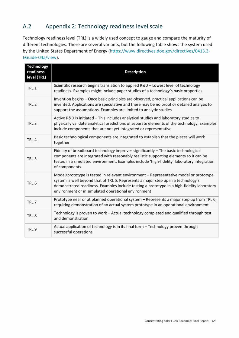
Concentrating Solar Fuels Roadmap: Final Report | 123
A.2 Appendix 2: Technology readiness level scale
Technology readiness level (TRL) is a widely used concept to gauge and compare the maturity of
different technologies. There are several variants, but the following table shows the system used
by the United States Department of Energy (https://www.directives.doe.gov/directives/0413.3-
EGuide-04a/view).
Technology readiness level (TRL)
Description
TRL 1 Scientific research begins translation to applied R&D – Lowest level of technology readiness. Examples might include paper studies of a technology’s basic properties
TRL 2 Invention begins – Once basic principles are observed, practical applications can be invented. Applications are speculative and there may be no proof or detailed analysis to support the assumptions. Examples are limited to analytic studies
TRL 3 Active R&D is initiated – This includes analytical studies and laboratory studies to physically validate analytical predictions of separate elements of the technology. Examples include components that are not yet integrated or representative
TRL 4 Basic technological components are integrated to establish that the pieces will work together
TRL 5
Fidelity of breadboard technology improves significantly – The basic technological components are integrated with reasonably realistic supporting elements so it can be tested in a simulated environment. Examples include ‘high-fidelity’ laboratory integration of components
TRL 6
Model/prototype is tested in relevant environment – Representative model or prototype system is well beyond that of TRL 5. Represents a major step up in a technology’s demonstrated readiness. Examples include testing a prototype in a high-fidelity laboratory environment or in simulated operational environment
TRL 7 Prototype near or at planned operational system – Represents a major step up from TRL 6, requiring demonstration of an actual system prototype in an operational environment
TRL 8 Technology is proven to work – Actual technology completed and qualified through test and demonstration
TRL 9 Actual application of technology is in its final form – Technology proven through successful operations
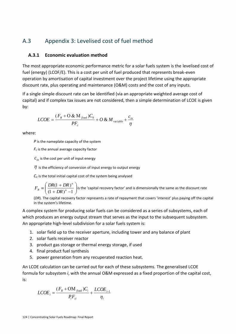
124 | Concentrating Solar Fuels Roadmap: Final Report
A.3 Appendix 3: Levelised cost of fuel method
A.3.1 Economic evaluation method
The most appropriate economic performance metric for a solar fuels system is the levelised cost of
fuel (energy) (LCOF/E). This is a cost per unit of fuel produced that represents break-even
operation by amortisation of capital investment over the project lifetime using the appropriate
discount rate, plus operating and maintenance (O&M) costs and the cost of any inputs.
If a single simple discount rate can be identified (via an appropriate weighted average cost of
capital) and if complex tax issues are not considered, then a simple determination of LCOE is given
by:
where:
P is the nameplate capacity of the system
Fc is the annual average capacity factor
is the cost per unit of input energy
is the efficiency of conversion of input energy to output energy
Co is the total initial capital cost of the system being analysed
is the 'capital recovery factor' and is dimensionally the same as the discount rate
(DR). The capital recovery factor represents a rate of repayment that covers 'interest' plus paying off the capital in the system’s lifetime.
A complex system for producing solar fuels can be considered as a series of subsystems, each of
which produces an energy output stream that serves as the input to the subsequent subsystem.
An appropriate high-level subdivision for a solar fuels system is:
1. solar field up to the receiver aperture, including tower and any balance of plant
2. solar fuels receiver reactor
3. product gas storage or thermal energy storage, if used
4. final product fuel synthesis
5. power generation from any recuperated reaction heat.
An LCOE calculation can be carried out for each of these subsystems. The generalised LCOE
formula for subsystem i, with the annual O&M expressed as a fixed proportion of the capital cost,
is:
in
iable
c
fixedR cMO
PF
CFLCOE
var&
inc
n
n
RDR
DRDRF
i
i
cii
ifixedR
i
LCOE
FP
CFLCOE
1
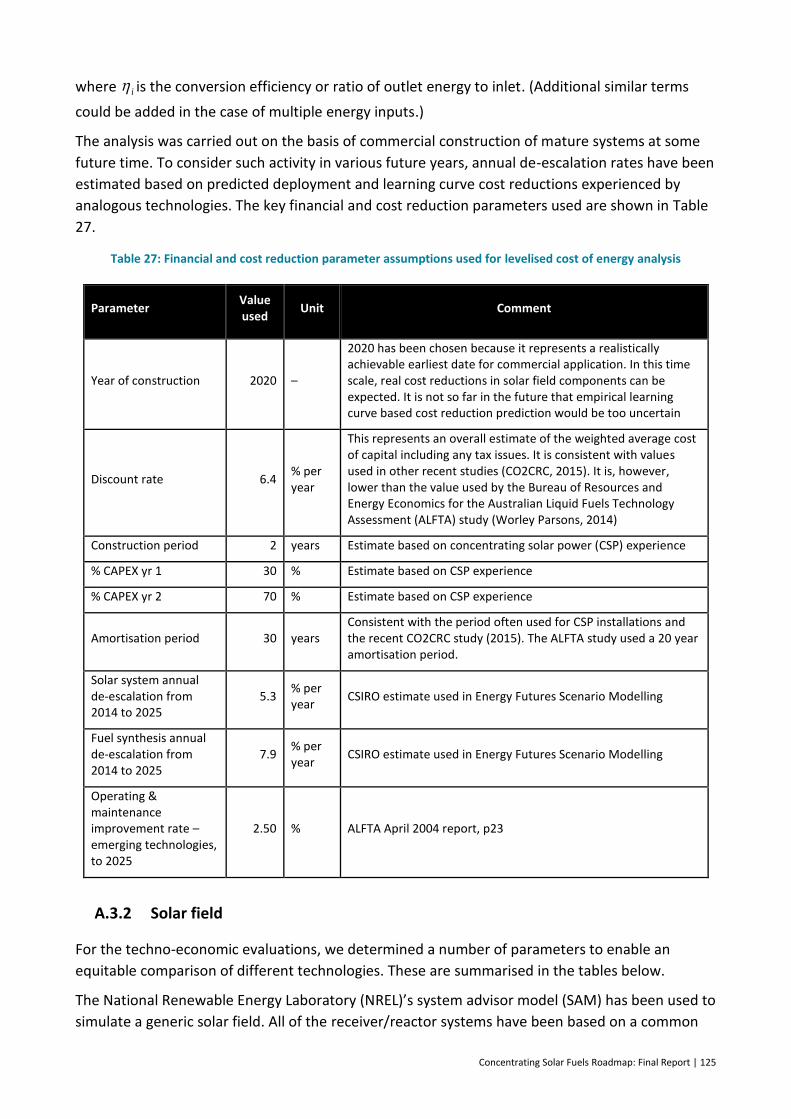
Concentrating Solar Fuels Roadmap: Final Report | 125
where is the conversion efficiency or ratio of outlet energy to inlet. (Additional similar terms
could be added in the case of multiple energy inputs.)
The analysis was carried out on the basis of commercial construction of mature systems at some
future time. To consider such activity in various future years, annual de-escalation rates have been
estimated based on predicted deployment and learning curve cost reductions experienced by
analogous technologies. The key financial and cost reduction parameters used are shown in Table
27.
Table 27: Financial and cost reduction parameter assumptions used for levelised cost of energy analysis
Parameter Value used
Unit Comment
Year of construction 2020 –
2020 has been chosen because it represents a realistically achievable earliest date for commercial application. In this time scale, real cost reductions in solar field components can be expected. It is not so far in the future that empirical learning curve based cost reduction prediction would be too uncertain
Discount rate 6.4 % per year
This represents an overall estimate of the weighted average cost of capital including any tax issues. It is consistent with values used in other recent studies (CO2CRC, 2015). It is, however, lower than the value used by the Bureau of Resources and Energy Economics for the Australian Liquid Fuels Technology Assessment (ALFTA) study (Worley Parsons, 2014)
Construction period 2 years Estimate based on concentrating solar power (CSP) experience
% CAPEX yr 1 30 % Estimate based on CSP experience
% CAPEX yr 2 70 % Estimate based on CSP experience
Amortisation period 30 years Consistent with the period often used for CSP installations and the recent CO2CRC study (2015). The ALFTA study used a 20 year amortisation period.
Solar system annual de-escalation from 2014 to 2025
5.3 % per year
CSIRO estimate used in Energy Futures Scenario Modelling
Fuel synthesis annual de-escalation from 2014 to 2025
7.9 % per year
CSIRO estimate used in Energy Futures Scenario Modelling
Operating & maintenance improvement rate – emerging technologies, to 2025
2.50 % ALFTA April 2004 report, p23
A.3.2 Solar field
For the techno-economic evaluations, we determined a number of parameters to enable an
equitable comparison of different technologies. These are summarised in the tables below.
The National Renewable Energy Laboratory (NREL)’s system advisor model (SAM) has been used to
simulate a generic solar field. All of the receiver/reactor systems have been based on a common
i
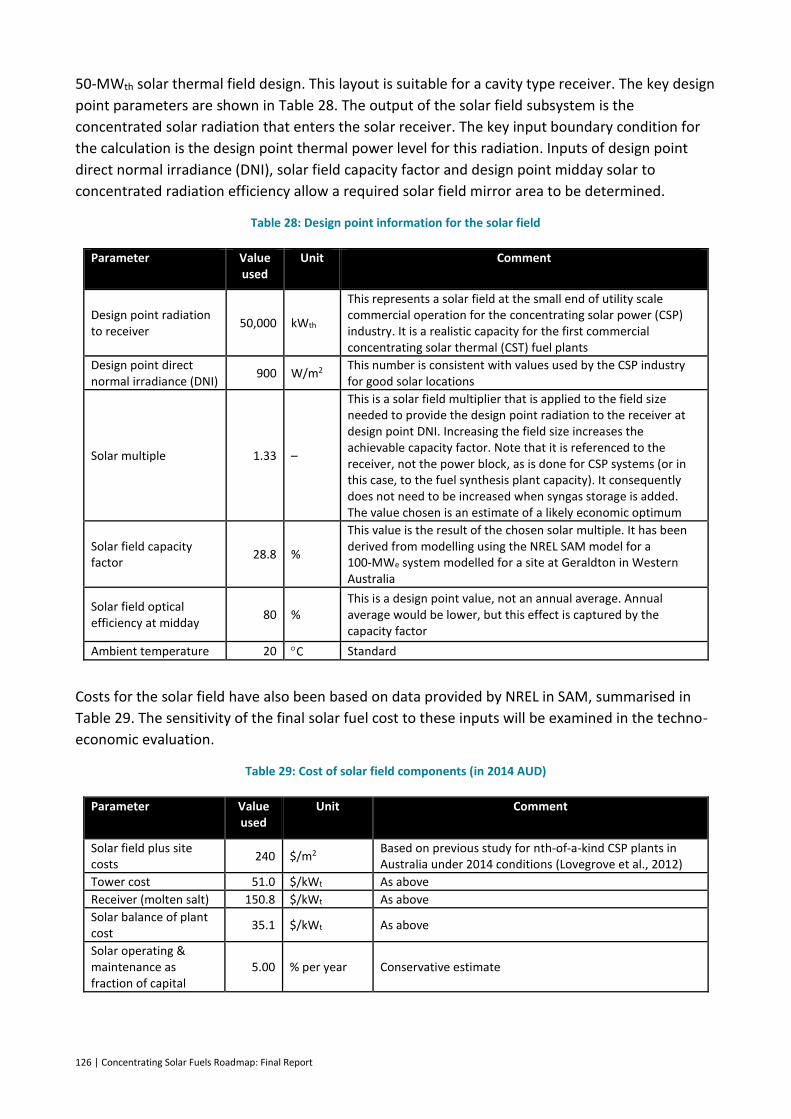
126 | Concentrating Solar Fuels Roadmap: Final Report
50-MWth solar thermal field design. This layout is suitable for a cavity type receiver. The key design
point parameters are shown in Table 28. The output of the solar field subsystem is the
concentrated solar radiation that enters the solar receiver. The key input boundary condition for
the calculation is the design point thermal power level for this radiation. Inputs of design point
direct normal irradiance (DNI), solar field capacity factor and design point midday solar to
concentrated radiation efficiency allow a required solar field mirror area to be determined.
Table 28: Design point information for the solar field
Parameter Value used
Unit Comment
Design point radiation to receiver
50,000 kWth
This represents a solar field at the small end of utility scale commercial operation for the concentrating solar power (CSP) industry. It is a realistic capacity for the first commercial concentrating solar thermal (CST) fuel plants
Design point direct normal irradiance (DNI)
900 W/m2 This number is consistent with values used by the CSP industry for good solar locations
Solar multiple 1.33 –
This is a solar field multiplier that is applied to the field size needed to provide the design point radiation to the receiver at design point DNI. Increasing the field size increases the achievable capacity factor. Note that it is referenced to the receiver, not the power block, as is done for CSP systems (or in this case, to the fuel synthesis plant capacity). It consequently does not need to be increased when syngas storage is added. The value chosen is an estimate of a likely economic optimum
Solar field capacity factor
28.8 %
This value is the result of the chosen solar multiple. It has been derived from modelling using the NREL SAM model for a 100-MWe system modelled for a site at Geraldton in Western Australia
Solar field optical efficiency at midday
80 % This is a design point value, not an annual average. Annual average would be lower, but this effect is captured by the capacity factor
Ambient temperature 20 C Standard
Costs for the solar field have also been based on data provided by NREL in SAM, summarised in
Table 29. The sensitivity of the final solar fuel cost to these inputs will be examined in the techno-
economic evaluation.
Table 29: Cost of solar field components (in 2014 AUD)
Parameter Value used
Unit Comment
Solar field plus site costs
240 $/m2 Based on previous study for nth-of-a-kind CSP plants in Australia under 2014 conditions (Lovegrove et al., 2012)
Tower cost 51.0 $/kWt As above
Receiver (molten salt) 150.8 $/kWt As above
Solar balance of plant cost
35.1 $/kWt As above
Solar operating & maintenance as fraction of capital
5.00 % per year Conservative estimate
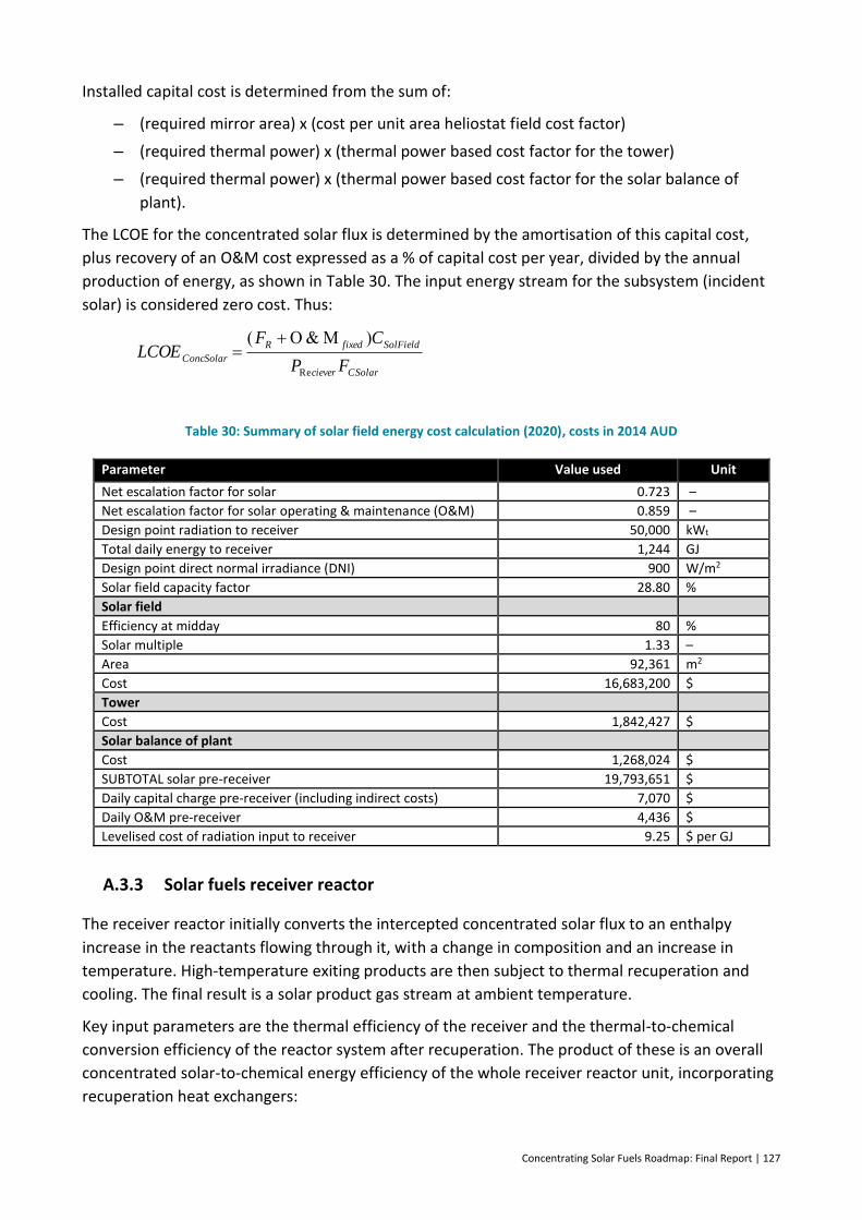
Concentrating Solar Fuels Roadmap: Final Report | 127
Installed capital cost is determined from the sum of:
– (required mirror area) x (cost per unit area heliostat field cost factor)
– (required thermal power) x (thermal power based cost factor for the tower)
– (required thermal power) x (thermal power based cost factor for the solar balance of
plant).
The LCOE for the concentrated solar flux is determined by the amortisation of this capital cost,
plus recovery of an O&M cost expressed as a % of capital cost per year, divided by the annual
production of energy, as shown in Table 30. The input energy stream for the subsystem (incident
solar) is considered zero cost. Thus:
Table 30: Summary of solar field energy cost calculation (2020), costs in 2014 AUD
Parameter Value used Unit
Net escalation factor for solar 0.723 –
Net escalation factor for solar operating & maintenance (O&M) 0.859 –
Design point radiation to receiver 50,000 kWt
Total daily energy to receiver 1,244 GJ
Design point direct normal irradiance (DNI) 900 W/m2
Solar field capacity factor 28.80 %
Solar field
Efficiency at midday 80 %
Solar multiple 1.33 –
Area 92,361 m2
Cost 16,683,200 $
Tower
Cost 1,842,427 $
Solar balance of plant
Cost 1,268,024 $
SUBTOTAL solar pre-receiver 19,793,651 $
Daily capital charge pre-receiver (including indirect costs) 7,070 $
Daily O&M pre-receiver 4,436 $
Levelised cost of radiation input to receiver 9.25 $ per GJ
A.3.3 Solar fuels receiver reactor
The receiver reactor initially converts the intercepted concentrated solar flux to an enthalpy
increase in the reactants flowing through it, with a change in composition and an increase in
temperature. High-temperature exiting products are then subject to thermal recuperation and
cooling. The final result is a solar product gas stream at ambient temperature.
Key input parameters are the thermal efficiency of the receiver and the thermal-to-chemical
conversion efficiency of the reactor system after recuperation. The product of these is an overall
concentrated solar-to-chemical energy efficiency of the whole receiver reactor unit, incorporating
recuperation heat exchangers:
CSolarciever
SolFieldfixedR
ConcSolarFP
CFLCOE
Re
128 | Concentrating Solar Fuels Roadmap: Final Report
The exit energy stream is the sum of the energy value of the initial feedstock and the solar input
that is converted. It is useful to define energy flows based on the steady state design point flows
and enthalpies of reactants at ambient temperature as follows:
The enthalpies are essentially the enthalpies of combustion. X is the exit conversion from the solar
reactor (<= 100%).
Note that in the case of water-splitting reactions, for example, is zero, but for hybrid
systems, it represents a major energy input stream.
These energy flux quantities can be related linearly as:
Which could also be expressed as:
The energy balance for the system also implies:
Thus, the LCOE of the final ambient temperature solar product gas is calculated with both the
concentrated radiation and the feedstock energy as inputs.:
where cFeedstock is the cost per unit energy of the feedstock.
In this calculation, the efficiency of conversion from concentrated solar to chemical determines
the relative amount of input energy per output, and also is a factor in the amount of output
energy over which the incremental capital cost and O&M contribution of the receiver system must
be amortised.
The thermal efficiency of the receiver quantifies the efficiency of conversion of the intercepted
concentrated solar radiation to an enthalpy increase (both chemical and sensible heat) in the
reactant stream prior to recuperation and cooling:
ChemThermalmalcieverTherChemSol Re
conversion
ambient
iiFeedstockhnQ
%0
..
conversion
ambient
ii hnQ%100
.
%100
.
conversionX
ambient
iioductsSolarhnQ
%
.
Pr
.
FeedstockQ.
FeedstockFeedstockoductsSolarQQXQQ.
%100
..
Pr
.
hXnQQ STFeedstockoductsSolar
..
Pr
.
ChemSolcieverFeedstockoductssolarPQQ _Re
.
Pr
.
oductsSolar
FeedstockFeedstock
oductsSolar
ceiverConcSolar
CSolaroductsSolar
ceiverfixedR
oductsSolar
Q
Qc
Q
PLCOE
FQ
CFLCOE
Pr
.
.
Pr
.
Re
Pr
.
Re
Pr
Concentrating Solar Fuels Roadmap: Final Report | 129
Receiver thermal efficiency is thus determined by energy losses due to:
– reflection of incident radiation
– thermal re-radiation (proportional to )
– convection (proportional to )
– cyclic heating of receiver mass (proportional to )
– conduction through receiver walls (proportional to ).
In reality, receivers have complex geometries and varying temperature distributions across their
surfaces. For the approximate modelling of receiver thermal efficiency, a semi-empirical approach
was taken. Noting that is a fixed input for this analysis, the efficiency is assumed to be a
combination of components proportional to a single representative temperature, plus a term
proportional to temperature to the fourth power:
The coefficients A and B are inputs chosen to match a baseline, known receiver thermal efficiency.
Temperatures are absolute. In this approach, reflection losses are ignored.
Thermal to chemical efficiency
The efficiency of conversion of the overall enthalpy increase within the receiver to the enthalpy
increase at ambient temperature can be expressed as:
The receiver reactor system can be considered as having two mass flow streams entering it:
– Stream 1, a stoichiometric mixture of reactants
– Stream 2, any excess of a subset of reactants or other non-reacting species (e.g., inert
sweep gas).
The exit mass flows can be characterised as:
– Stream 3, the fraction of the stoichiometric mix that is converted
– Stream 4, the fraction that is unconverted
– Stream 5, the excess/non-reacting material that is unchanged.
Streams 1 and 2 must be heated from ambient to reactor temperature, either by recuperation of
heat from the exit streams or from the solar input. The exit streams are all cooled to ambient
temperature by a combination of recuperation and the loss of any residual sensible heat to the
environment. The recuperation process itself will have a nominated thermal efficiency, which is
ConcSolar
LossConcSolaralciverTherm
Q
QQ.
..
Re
ambientceiver TT 4Re
4
ambientceiver TT Re
ambientceiver TT Re
ambientceiver TT Re
ConcSolarQ.
ambientceiverambientceiveralciverTherm TTBTTA 4Re
4
ReRe 1
LossConcSolar
ST
LossConcSolar
FeedstockoductsSolarChemicalThermal
hXn
QQ..
.
..
.
Pr
.
_
130 | Concentrating Solar Fuels Roadmap: Final Report
determined by a combination of the quality of the heat exchanger, any mismatch in
temperature/enthalpy relationships, and any pragmatic considerations, such as a need for rapid
quenching to avoid reverse reactions. The overall thermal to chemical efficiency is determined by
the overall level of thermal loss from the recuperation process compared with the amount of
energy absorbed by the reaction.
The net thermal energy input to the receiver must be balanced by the increase in chemical energy
from feedstock to products after they are cooled to ambient temperature, plus the sensible heat
that is lost due to imperfect recuperation:
where the energy lost from imperfect recuperation is:
and hence:
A.3.4 Product gas storage or thermal energy storage (if used)
The possible addition of solar product gas storage to allow final fuel synthesis to operate at higher
capacity factor is assumed to have an efficiency of unity, but to add a capital cost component.
Thus:
A.3.5 Final product fuel synthesis
Final product synthesis is characterised by a potentially independent capacity and capacity factor.
However, we assume that all the solar product gas is processed by the fuel synthesis plant over an
extended time, such that:
.....
RClossSTLossConcSolarQhXnQQ
oducts
ambientiRcceiveriicupRClossThThnQ
Pr
.
Re
.
)()(1
..
.
_
RClossST
STChemTherm
QhXn
hXn
.
Pr
.
Re
.
.
_
)()(1
oducts
ambientiRcceiveriicupST
STChemTherm
ThThnhXn
hXn
hn
ThThn
XST
oducts
ambientiRcceiverii
cup
.
Pr
.
Re
)()(1
1
1
1
Pr
Re
.ProductGasSolar
ChemSolCSolarceiverFeedstock
StorefixedR
oductGasStored
LCOE
FPQ
CFLCOE
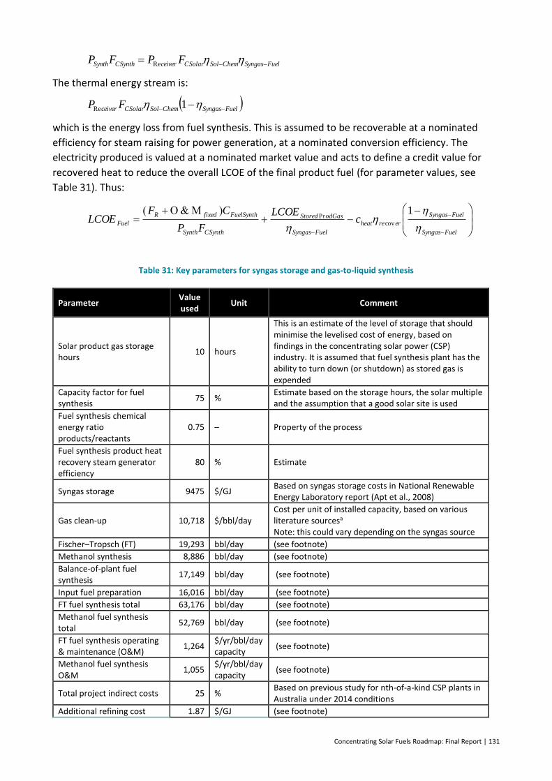
Concentrating Solar Fuels Roadmap: Final Report | 131
The thermal energy stream is:
which is the energy loss from fuel synthesis. This is assumed to be recoverable at a nominated
efficiency for steam raising for power generation, at a nominated conversion efficiency. The
electricity produced is valued at a nominated market value and acts to define a credit value for
recovered heat to reduce the overall LCOE of the final product fuel (for parameter values, see
Table 31). Thus:
Table 31: Key parameters for syngas storage and gas-to-liquid synthesis
Parameter Value used
Unit Comment
Solar product gas storage hours
10 hours
This is an estimate of the level of storage that should minimise the levelised cost of energy, based on findings in the concentrating solar power (CSP) industry. It is assumed that fuel synthesis plant has the ability to turn down (or shutdown) as stored gas is expended
Capacity factor for fuel synthesis
75 % Estimate based on the storage hours, the solar multiple and the assumption that a good solar site is used
Fuel synthesis chemical energy ratio products/reactants
0.75 – Property of the process
Fuel synthesis product heat recovery steam generator efficiency
80 % Estimate
Syngas storage 9475 $/GJ Based on syngas storage costs in National Renewable Energy Laboratory report (Apt et al., 2008)
Gas clean-up 10,718 $/bbl/day Cost per unit of installed capacity, based on various literature sourcesa Note: this could vary depending on the syngas source
Fischer–Tropsch (FT) 19,293 bbl/day (see footnote)
Methanol synthesis 8,886 bbl/day (see footnote)
Balance-of-plant fuel synthesis
17,149 bbl/day (see footnote)
Input fuel preparation 16,016 bbl/day (see footnote)
FT fuel synthesis total 63,176 bbl/day (see footnote)
Methanol fuel synthesis total
52,769 bbl/day (see footnote)
FT fuel synthesis operating & maintenance (O&M)
1,264 $/yr/bbl/day capacity
(see footnote)
Methanol fuel synthesis O&M
1,055 $/yr/bbl/day capacity
(see footnote)
Total project indirect costs 25 % Based on previous study for nth-of-a-kind CSP plants in Australia under 2014 conditions
Additional refining cost 1.87 $/GJ (see footnote)
FuelSyngasChemSolCSolarceiverCSynthSynth FPFP Re
FuelSyngasChemSolCSolarceiver FP 1Re
FuelSyngas
FuelSyngas
erreheat
FuelSyngas
odGasStored
CSynthSynth
FuelSynthfixedR
Fuel cLCOE
FP
CFLCOE
1cov
Pr
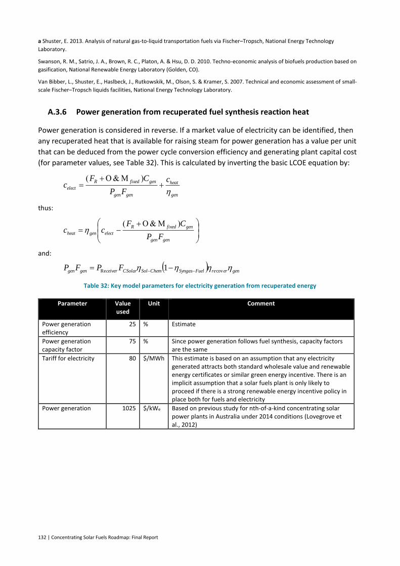
132 | Concentrating Solar Fuels Roadmap: Final Report
a Shuster, E. 2013. Analysis of natural gas-to-liquid transportation fuels via Fischer–Tropsch, National Energy Technology
Laboratory.
Swanson, R. M., Satrio, J. A., Brown, R. C., Platon, A. & Hsu, D. D. 2010. Techno-economic analysis of biofuels production based on
gasification, National Renewable Energy Laboratory (Golden, CO).
Van Bibber, L., Shuster, E., Haslbeck, J., Rutkowskik, M., Olson, S. & Kramer, S. 2007. Technical and economic assessment of small-
scale Fischer–Tropsch liquids facilities, National Energy Technology Laboratory.
A.3.6 Power generation from recuperated fuel synthesis reaction heat
Power generation is considered in reverse. If a market value of electricity can be identified, then
any recuperated heat that is available for raising steam for power generation has a value per unit
that can be deduced from the power cycle conversion efficiency and generating plant capital cost
(for parameter values, see Table 32). This is calculated by inverting the basic LCOE equation by:
thus:
and:
Table 32: Key model parameters for electricity generation from recuperated energy
Parameter Value used
Unit Comment
Power generation efficiency
25 % Estimate
Power generation capacity factor
75 % Since power generation follows fuel synthesis, capacity factors are the same
Tariff for electricity 80 $/MWh This estimate is based on an assumption that any electricity generated attracts both standard wholesale value and renewable energy certificates or similar green energy incentive. There is an implicit assumption that a solar fuels plant is only likely to proceed if there is a strong renewable energy incentive policy in place both for fuels and electricity
Power generation 1025 $/kWe Based on previous study for nth-of-a-kind concentrating solar power plants in Australia under 2014 conditions (Lovegrove et al., 2012)
gen
heat
gengen
genfixedR
elect
c
FP
CFc
gengen
genfixedR
electgenheatFP
CFcc
generreFuelSyngasChemSolCSolarceivergengen FPFP covRe 1
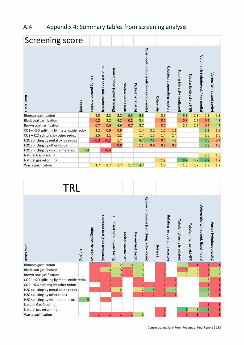
Concentrating Solar Fuels Roadmap: Final Report | 133
A.4 Appendix 4: Summary tables from screening analysis
Screening score
Ro
w Lab
els
F r (any)
Falling p
article re
ceive
r
Fluid
ised
be
d (sid
e irrad
iated
)
Fluid
ised
be
d (u
pw
ard facin
g)
Mo
lten
me
dia b
ath
Packe
d b
ed
(batch
)
Qu
asi-con
tinu
ou
s (switch
ing re
do
x mo
de
)
Ro
tary kiln
Ro
tating re
cup
eratin
g reacto
rs
Tub
ular (d
irectly irrad
iated
)
Tub
ular (in
dire
ct via HTF)
Vo
lum
etric (w
ind
ow
ed
, fixed
me
dia)
Vo
rtex (w
ind
ow
ed
cavity)
Biomass gasification 2.3 2.2 3.2 5.3 5.3 2.3 5.3 2.3 2.3 2.3
Black coal gasification 0.2 3.2 4.2 0.2 3.4 0.2 0.3 2.2 0.2 4.3
Brown coal gasification 0.7 0.6 4.6 0.7 3.7 0.7 2.7 2.7 0.7 4.7
CO2 + H2O splitting by metal oxide redox 1.2 0.9 0.9 1.4 3.2 1.1 1.1 5.2 1.3
CO2 +H2O splitting by other redox 3.5 1.1 1.1 1.7 1.5 1.4 1.4 1.5 1.6
H2O splitting by metal oxide redox -0.4 -0.3 1.7 4.7 7.5 0.4 4.3 7.6 0.7
H2O splitting by other redox 0.0 1.1 0.9 0.8 0.7 5.9 1.0
H2O splitting by volatile metal ox 5.4 -0.3
Natural Gas Cracking 2.3 1.8
Natural gas reforming 1.2 9.2 4.2 9.2 1.2
Waste gasification 1.7 1.7 1.7 1.7 4.7 1.7 1.8 1.7 1.7 1.7
Ro
w Lab
els
F r (any)
Falling p
article re
ceive
r
Fluid
ised
be
d (sid
e irrad
iated
)
Fluid
ised
be
d (u
pw
ard facin
g)
Mo
lten
me
dia b
ath
Packe
d b
ed
(batch
)
Qu
asi-con
tinu
ou
s (switch
ing re
do
x mo
de
)
Ro
tary kiln
Ro
tating re
cup
eratin
g reacto
rs
Tub
ular (d
irectly irrad
iated
)
Tub
ular (in
dire
ct via HTF)
Vo
lum
etric (w
ind
ow
ed
, fixed
me
dia)
Vo
rtex (w
ind
ow
ed
cavity)
Biomass gasification 1 1 2 3 3 1 3 1 1 1
Black coal gasification 1 3 3 1 3 1 1 2 1 3
Brown coal gasification 1 1 3 1 3 1 2 2 1 3
CO2 + H2O splitting by metal oxide redox 1 1 1 1 1 1 3 1
CO2 +H2O splitting by other redox 1 1 1 1 1 1 1 1
H2O splitting by metal oxide redox 1 1 2 2 5 1 4 5 1
H2O splitting by other redox 1 1 1 1 1 4 1
H2O splitting by volatile metal ox 5 1
Natural Gas Cracking 1 1
Natural gas reforming 1 6 3 6 1
Waste gasification 1 1 1 1 3 1 1 1 1 1
TRL
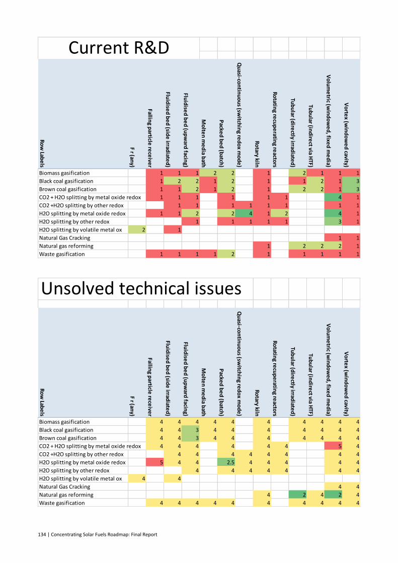
134 | Concentrating Solar Fuels Roadmap: Final Report
Ro
w Lab
els
F r (any)
Falling p
article re
ceive
r
Fluid
ised
be
d (sid
e irrad
iated
)
Fluid
ised
be
d (u
pw
ard facin
g)
Mo
lten
me
dia b
ath
Packe
d b
ed
(batch
)
Qu
asi-con
tinu
ou
s (switch
ing re
do
x mo
de
)
Ro
tary kiln
Ro
tating re
cup
eratin
g reacto
rs
Tub
ular (d
irectly irrad
iated
)
Tub
ular (in
dire
ct via HTF)
Vo
lum
etric (w
ind
ow
ed
, fixed
me
dia)
Vo
rtex (w
ind
ow
ed
cavity)
Biomass gasification 1 1 1 2 2 1 2 1 1 1
Black coal gasification 1 2 2 1 2 1 1 2 1 3
Brown coal gasification 1 1 2 1 2 1 2 2 1 3
CO2 + H2O splitting by metal oxide redox 1 1 1 1 1 1 4 1
CO2 +H2O splitting by other redox 1 1 1 1 1 1 1 1
H2O splitting by metal oxide redox 1 1 2 2 4 1 2 4 1
H2O splitting by other redox 1 1 1 1 1 3 1
H2O splitting by volatile metal ox 2 1
Natural Gas Cracking 1 1
Natural gas reforming 1 2 2 2 1
Waste gasification 1 1 1 1 2 1 1 1 1 1
Current R&D
Unsolved technical issues
Ro
w Lab
els
F r (any)
Falling p
article re
ceive
r
Fluid
ised
be
d (sid
e irrad
iated
)
Fluid
ised
be
d (u
pw
ard facin
g)
Mo
lten
me
dia b
ath
Packe
d b
ed
(batch
)
Qu
asi-con
tinu
ou
s (switch
ing re
do
x mo
de
)
Ro
tary kiln
Ro
tating re
cup
eratin
g reacto
rs
Tub
ular (d
irectly irrad
iated
)
Tub
ular (in
dire
ct via HTF)
Vo
lum
etric (w
ind
ow
ed
, fixed
me
dia)
Vo
rtex (w
ind
ow
ed
cavity)
Biomass gasification 4 4 4 4 4 4 4 4 4 4
Black coal gasification 4 4 3 4 4 4 4 4 4 4
Brown coal gasification 4 4 3 4 4 4 4 4 4 4
CO2 + H2O splitting by metal oxide redox 4 4 4 4 4 4 5 4
CO2 +H2O splitting by other redox 4 4 4 4 4 4 4 4
H2O splitting by metal oxide redox 5 4 4 2.5 4 4 4 4 4
H2O splitting by other redox 4 4 4 4 4 4 4
H2O splitting by volatile metal ox 4 4
Natural Gas Cracking 4 4
Natural gas reforming 4 2 4 2 4
Waste gasification 4 4 4 4 4 4 4 4 4 4


136 | Concentrating Solar Fuels Roadmap: Final Report
CONTACT US
t 1300 363 400 +61 3 9545 2176 e [email protected] w www.csiro.au
AT CSIRO WE SHAPE THE FUTURE
We do this by using science to solve real issues. Our research makes a difference to industry, people and the planet.
As Australia’s national science agency we’ve been pushing the edge of what’s possible for over 85 years. Today we have more than 5,000 talented people working out of 50-plus centres in Australia and internationally. Our people work closely with industry and communities to leave a lasting legacy. Collectively, our innovation and excellence places us in the top ten applied research agencies in the world.
WE ASK, WE SEEK AND WE SOLVE
FOR FURTHER INFORMATION
CSIRO Energy – Solar Thermal Dr Jim Hinkley t +61 2 4960 6128 e [email protected] w www.csiro.au/energy CSIRO Energy – Solar Thermal Robbie McNaughton t +61 2 4960 6047 e [email protected] w www.csiro.au/energy CSIRO Energy – Grids and Energy Efficiency Systems Dr Jenny Hayward t +61 2 4960 6198 e [email protected] w www.csiro.au/energy