Onager physics
70
1 Onager Physics By Donald Siano [email protected] July 11, 2001 Introduction The Onager is a medieval catapult powered by a single bundle of twisted ropes. Very little has been published (1,2) on the physics involved in the design of the device, which has done almost entirely by empirical methods. It would therefore be of interest to apply some simple physical analysis to see what can be done to increase our understanding of this seemingly simple device. Our approach will be to devise a couple of simple models for the device, and to analyze them using elementary physical considerations to derive analytical expressions for the torque on the beam as a function of the Onager dimensions and the configurations of the skein. We hope to thereby arrive at a level of explanation that encompasses enough of the mechanism to be assured that the essence of the machine is captured, but not so complex that it is useless to all but the professional mathematician. The ropes in the bundle or skein can be configured in a myriad of ways, none of which appear to have been described before, or even named. Therefore the examination of the properties of the skein will be the central focus of this paper. We want to understand where the torque comes from, where the energy goes, describe some measures of efficiency of the device and the trade-offs involved in design. We want to have some rational method for choosing the material that will give the best performance and how to best expoit those characteristics. We would also welcome some general guidlines on the scaling properties of the Onager: how does the energy in the skein scale with the linear dimensions of the parts? How does the range of the projectile scale? How should we scale the parts so they don't break? The dynamics of the throw when the beam is released will be treated separately, hopefully, in another paper in this series. The Geometry Fig. 1 shows two schematic views of an Onager: one from the side, and the other from above. The twisted skein or bundle of twisted ropes are separated into two parts by a beam, which is held tightly under tension from the bundle. The tension in the skein is produced by means of one (or two) rotating capstans through which the skein is guided. When the Onager is cocked, the beam is held by some trigger mechanism as shown, the projectile placed in the sling, then released. During the throw, the beam rotates very quickly to a vertical position, where it is stopped by the
-
Upload
sergiu-ivan -
Category
Documents
-
view
23 -
download
2
description
High detail theoretical calculations of forces and variables that occur in construction or firing a projectile with this siege equipment
Transcript of Onager physics

1
Onager Physics
By Donald [email protected]
July 11, 2001
IntroductionThe Onager is a medieval catapult powered by a single bundle of twisted ropes.Very little has been published (1,2) on the physics involved in the design ofthe device, which has done almost entirely by empirical methods. It wouldtherefore be of interest to apply some simple physical analysis to see what canbe done to increase our understanding of this seemingly simple device.
Our approach will be to devise a couple of simple models for the device, and toanalyze them using elementary physical considerations to derive analyticalexpressions for the torque on the beam as a function of the Onager dimensionsand the configurations of the skein. We hope to thereby arrive at a level ofexplanation that encompasses enough of the mechanism to be assured that theessence of the machine is captured, but not so complex that it is useless to allbut the professional mathematician.
The ropes in the bundle or skein can be configured in a myriad of ways, noneof which appear to have been described before, or even named. Therefore theexamination of the properties of the skein will be the central focus of thispaper. We want to understand where the torque comes from, where the energygoes, describe some measures of efficiency of the device and the trade-offsinvolved in design. We want to have some rational method for choosing thematerial that will give the best performance and how to best expoit thosecharacteristics.
We would also welcome some general guidlines on the scaling properties of theOnager: how does the energy in the skein scale with the linear dimensions ofthe parts? How does the range of the projectile scale? How should we scale theparts so they don't break?
The dynamics of the throw when the beam is released will be treatedseparately, hopefully, in another paper in this series.
The GeometryFig. 1 shows two schematic views of an Onager: one from the side, and theother from above. The twisted skein or bundle of twisted ropes are separatedinto two parts by a beam, which is held tightly under tension from the bundle.The tension in the skein is produced by means of one (or two) rotatingcapstans through which the skein is guided.
When the Onager is cocked, the beam is held by some trigger mechanism asshown, the projectile placed in the sling, then released. During the throw, thebeam rotates very quickly to a vertical position, where it is stopped by the

2
padded stopping bar. When the beam rotates CCW, the sling with the projectilerotates outward to the left. At some point in the rotation, the sling opens up,releasing the projectile, which flies off to the right, hopefully bustingsomething not on the Onager.
capstan
beam
skein
beam
sling
side view
stopping bar
projectile yoke
Fig. 1. The Onager and its parts defined.
The Torque on the Beam
The object of central interest in our models is, of course, the torque imparted tothe beam by the rope bundle. We'd like to know, for example, how the torquevaries with the position of the beam, the tension in the ropes of the bundle,and the dimensions of the bundle, the yoke and the beam. We'd like to be ableto use this to look at the forces tending to break the parts of the Onager inorder to make its design and construction more rational.

3
First, we need to review some simple stuff about what torque is, and how itarises in the Onager.
Torque is the quantity that makes the beam rotate, so it is rather important inwhat follows to have a good understanding of it. Appendix I contains a generaldiscussion of torque and how to calculate it for readers who need a little bit ofbrushing up on their high school physics.
Tension in a RopeThe force that creates the torque in the Onager is the tension of the ropes inthe bundle. We think of a flexible string. The force communicated by astretched flexible string is called the tension. It can act only along thedirection of the string. If we connect two bodies by a stretched string, thenthe tension acts in a direction tending to draw the two bodies together.Flexible strings cannot provide thrust, a force tending to separate the twobodies. Consider a simple example:
ϕ
T T
ϕA
PTx Tx
Ty
B
Fig. 2 Example of two strings under a tension T pressing atriangular beam into a base.
Here a string is attached to a base at A, then to the apex, P, of a beam that has atriangular cross-section. Another string goes from P to B that is under thesame tension T. The string makes an angle ϕ with respect to the base. TheTensions can be resolved in the horizontal and vertical directions as shown.We can easily see that force acting at the apex in the horizontal direction iszero because the two components cancel. In the vertical direction, the twocomponents of the tension add, so the force pressing the beam into the base isjust F = 2 T cos(π/2-ϕ) = 2 T sin(ϕ). If we replace the two strings with a singlestring passing over the apex, under the same tension, the force pressing thebeam into the base would be unchanged.
The force pulling on A is also a vector along the string, with a magnitude T,but with a direction opposite to that shown. The force tending to draw the twopoints A and B together is then 2 T cosϕ).
One complication that must be faced in dealing with the Onager is that theskein or rope bundle is made from ropes that have a non-zero diameter, unlikethe strings of the usual mechanical models. In the system shown above amore realistic drawing of the actual set-up would be something like this:

4
A ϕ
C
l2
l1
Fig. 3. The rope is not a string!
Here in Fig. 3, the string is replaced by two parallel lines representing theouter limits of a rope with a certain definite diameter. A real rope is notfastened at a single point, nor does it contact a surface at a single point, unlikethe physicist's string. A rope is quite a complicated object--it consists ofoverlapping fibers that transmit forces between themselves by means of atheir very high mutual friction. Ropes have a certain stiffness and anisotropyin their properties. When placed under tension, their diameter shrinks alittle. They are extensible and compressible. And so on...
To make a tractable model the Onager, however, we still need to extract theright essential properties of the ropes comprising the skein. It will becomeclear later in our discussion that the most important factor is the finitediameter of the ropes needs to be retained.
Where then are we to draw our force vector representing the tension in therope? Although other choices might be made, for the purposes of our model,we will explicitly assume that the force vector representing the tension isdrawn from the point of contact, C, to the center of the point of attachment ofthe rope at A. This is an approximation which will much simplify our analysis.
Note that in this case, with the dimension l1 and l2 as shown, the forcepressing the beam into the base is
2 T sin(φ) = 2 T l2/sqrt(l2^2+l1^2)
which is useful in comparing results to be obtained (vide infra).
Dimensional Analysis of the Onager

5
A useful method to understand the properties of the Onager is to consider howthey scale with changes in dimension of the parts. Does one expect, forexample, an Onager that is twice as big to be twice as powerful? Is the torqueon the beam twice as great? Will it throw a given weight twice as far?
The parts of the Onager have been previously described: the distance betweenthe attachment points, 2 l1, the thickness of the beam, 2 l2, the diameter of therope, 2s, and the thickness of the attachment points, 2t. The tension in therope, T, is the principle force involved.
We assume that the frictional forces are negligible to a first approximation,and base our discussion on this. An Onager scaled by a factor of k, say, wouldhave a distance between the yoke of 2 k l1, beam thickness 2 k l2 and a ropediameter 2 k s.
A simple dimensional analysis (or, by inspection) of the problem of thetension then shows that the torque would be given by
τ = C f(l1/ s,l2/ s,t /s) s T
where C is some constant, and f is some undetermined function. The torque isproportional to the tension, which should come as no surprise.
The energy in the Onager is contained in the rope, and is proportional to itsvolume. Scaling the Onager by a factor k, would increase the volume of therope by a factor k l1 (k s)^2 or by k^3. That is, doubling the dimensions of theOnager would increase the energy in the bundle by 8 . So the scaled Onagerwould have an energy scaled by k^3.
Since the range of a projectile of mass m with initial kinetic energy E is (videinfra) proportional to E/m, we'd expect the range for a given mass to increaseby a factor of k^3 too. The range of a given mass for an Onager twice as largewould be greater by a factor of 8. Or a mass twice as great would go 4 times asfar...
The energy in the Onager scales with the 3rd power of its dimensions. Forcomparison, the trebuchet scales with the 4th power of its dimensions (volumeof counterweight x height).
In scaling up an Onager, an important question is "How should we scale theyoke? " It can be shown (see ref 3) that the maximum stress that a beam with asquare cross-section of thickness, r, supported in the middle, with the supportsa distance L apart, under a weight P scales as PL/r^3. This scales as k^2 k/k^3 =1. So a scaled Onager, with the thickness of the yoke increased by k, should beOK. It won't break.
The energy in the beam crashing into the stop will be proportional to theenergy in the skein, which, as we have seen, scales as the fifth power of thedimensions. This energy is dissipated into a volume of the beam. If the energydeposited per unit volume of the beam exceeds a certain value, the beam will
6
break or be crushed. Therefore to scale up an Onager by a factor of k requiresthat the volume of the beam in which the energy is dissipated be scaled by k^3.If this volume is proportional to the thickness of the beam cubed (squarecross-section), this requires that the thickness be increased by a factor ofk^(3/3). So doubling the size of the Onager requires that the thickness of the(square cross-sectional) beam be increased by a factor of 2. .
A Two Stranded String ModelWe want now to consider a string (zero radius) model first to introduce somefundamental ideas about how to picture the Onager configuration, set up ourcoordinate system and notation, and so on. This is the "two stranded stringmodel". We can easily modify the configuration shown in Fig. 2 to aconfiguration more like an Onager:
ϕ
T T
ϕA
P3
B
T TP4
2 l2ϕ ϕ
O
2 l1
Fig. 4. A beam with diamond cross-section being compressed bytwo strings.
Here A-P3-B are one strand of string (with zero radius) fastened at A and B,and A-P4-B is another strand fastened to the beam (which now has a diamondcross-section) at P4. The points of attachment A and B are fixed to the groundand can't move. The apexes are a distance 2 l2 apart. A-P4 -B-P3 are set-up tobe all in one plane. The base is gone and the beam is supported only at P3 andP4.
Then the force exerted by the string at P4 is now up and has the samemagnitude as the force at P3. The forces acting at P3 and P4 tend to compressthe beam in the vertical direction. As long as all of the tensions are equal, it isclear, and easy to show, that there is no torque about O. This model is not goodenough--something is left out.

7
One might imagine that a better model would have P3 and P4 displaced into andout of the paper by some (equal) amount. Would a torque on the beam beproduced then? It is not hard to set up a coordinate system, get the vectors ofthe tensions, and calculate the torque on the beam analytically as the crossproduct of vectors from O to the points P3 and P4. You'd again get a torque ofzero. Displacing the points of application of the tensions on the beam stillleaves something out.
An easier way to see this is by a consideration of the couples produced by thefour forces. Note that P1, P2, P3 and P4 are still co-planar. At P3 the forceshave a resultant in that plane that points downward towards P4. At P4, the twoforces also have a resultant that lies in that plane, and points upward towardsP3. That is, the two resultant forces are anti-parallel. However, they both actalong the same line P3-O-P4, which means that their moment arm is zero, sothe couple has a zero magnitude, and there is no turning force acting on thebeam.
This configuration of the string looks pretty much like an idealization of thebundle when the Onager is cocked, and so it may come as a surprise that thetorque is zero. So where does the torque in a real Onager come from?
One could suppose that the torque is produced by an asymmetry in the forcesor the positions of the points of application of the forces at P3 and P4. A torquewould certainly be produced, but this is not a very elegant route to take, andwould be quite ad-hockish. The Onager has a symmetry to it that the modelshould preserve.
What appears to be required, as we pointed out before, is to introduce the ideathat the rope (or sling bundle) radius has a definite non-zero value. Thismeans that the points at which the rope separates, P1 and P2 are not reallysingle points.
There is no torque induced in the Two Stranded String model.
Multi-Stranded Open Twisted Model One possibility involves a skein that is highly twisted, which contacts thebeam at a pair of points. Fig. 8 shows this idea embodied in a small model. Thecylindrical white object on the left is a capstan that holds a straight bar ofmetal rod, parallel to the yoke, that the rope can be wound around. Thisconfiguration is arrived at by imparting a few twists in the skein by means ofthe capstan, sliding them over to the right, inserting the beam, then windingthe capstan an equal number of turns in the same direction. The skein shownis composed of four strands that separate at a point some distance away fromthe beam, creating an opening, or gap there. We'll call this the "multi-stranded open twisted" model for the Onager skein.

8
Fig. 5. The open twisted bundle configuration when cocked.
To model this idea, referring to the previous figure, the point at P1 just beforethe untwisting of the rope bundle can be left where it is, and we can introducetwo new points, P5 and P6, which is the start of the rope's straight linetrajectory to the points of attachment to the beam. The region of rope betweenP1 and P3 can have some complicated shape, but we needn't worry about this.Similarly, it appears to be safe enough to leave the points of attachment of therope to the beam where it is, and as a single point. To see this model, considerthe diagram of the Onager with the beam now turned up, and the beam omittedfrom the drawing for greater clarity.

9
Open Twisted Onager Force Diagram
P1(-l3,0,0)
P2(l3,0,0)
P3(0,l2,-d)
P4(0,-l2,d)
2*l3
2*l2
2*l1
T
Ty
x
zo
P5
P6
P7
P8
A
B
d
C
Fig. 6. The open twisted Onager with points of attachment A and B,points of contact P3 and P4 and with the beginning of the eachuntwisted strand displaced by small amounts from the twistedbundle at P1 and P2.
The rope is fastened to the yoke of the Onager at A and B; it separates into 2strands at points P1 and P2 and pulls on the beam at the points of contact, P3and P4.
The origin of the coordinate system is midway along the line P1-P2, designatedby "O"; P1 is on the front left face of the parallelepiped, P2 is on the rear rightface.
P3 and P4 are the points where the rope contacts the beam (not shown) of theonager and the force coming from the rope acts at that point. The origin isalong the central axis of the beam.
Clearly, the point at which each strand becomes free from the other(s) has anx-coordinate that falls between P1 and P2. The transition region, where the
10
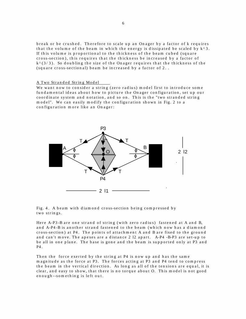
unwinding of the bundle occurs (for the upper strand it is the segment P1-P5.The points P5 and P6 are the points where a strand begins its (straight line)path to the point of contact with the beam.
Thus, P6 and P5 are both inside the parallelepiped. To summarize, the upperstrand of the rope follows the path A-P1-P5-P3-P7-P2-B and the lower strandfollows the path A-P1-P6-P4-P8-P2-B.
P5 is above and inward from P1: P5(-l3+d1,d2,-d3) where d1, d2, and d3 arepositive and, clearly, are lengths of order of the radius of the rope bundle.P6 is below and inward from P1: P6(-l3+d1,-d2,d3).
P3 and P4 are in the yz plane; P3, P4, O and C are all coplanar.P3 has coordinates (0,l2,-d) and P4 has coordinates (0,-l2,d), where d isSqrt(l2^2+l3^2) only if the parallelepiped is a rectangular parallelepiped.
A vector from P3 to P5 is (-l3+d1,d2,-d3)-(0,l2,-d) = (-l3+d1, d2-l2, -d3+d) ≡ v tlA vector from P4 to P6 is (-l3+d1,-d2,d3)-(0,-l2,d) = (-l3+d1, -d2+l2, d3-d) ≡v bl;v means vector, tl means "top left" strand, bl means bottom left strand.
The length of each of these vectors is Sqrt((-l3+d1)^2 + (d2-l2)^2 + (-d3+d)^2) =v, so a unit vector from P3 to P5 is v tl/v and a unit vector from P4 to P6 isv bl/v.
The magnitude of the tension in the half strands of the rope going from P3 toP5 is T', and that going from P4 to P6 is assumed, as before, to be the same.Therefore the vector of the force pulling from the left at P3 is T' v tl/v and thevector of the force pulling on P4 from the leftmost half-strand is T' v bl/v.
The vector from the origin, O, to the point where the force coming from thetop left half strand is (0,l2,-d)-(0,0,0) = (0,l2,-d) ≡ r tl. The torque, τ , about theorigin, due to the upper left half strand, is the cross product of r and theforce: τ tl= r tl x T' v tl/v, and similarly for the lower left half strand. Addingall four tourqes from the half strands will give the torque on the beam.
The calculation is easily done, and the result is that the total torque on thebeam is found to be
τ =4(d d2 − d3 l2) ′ T
(d − d3)2 + (d2 − l2) 2 + (d1− l3)2i
where i is a vector in the x-direction, and T' is the tension in each half strand.Note that when d3 = d2 = d1 = 0, we recover our result from before, that thetorque is zero. While, pretty general, this formula is not terribly useful as itstands.
When d3 = d2 = d1 = rb (effective radius of the bundle) then this simplifies to

11
τ =4(
d
rb − l2
rb) rb ′ T
(1− d
rb)2 + (1− l2
rb)2 + (1− l3
rb)2
i ,
where now all of the lengths have been scaled by the effective bundle radius,rb.
It is not hard to show that the tension in the half strands, T' is given by
′ T =d12 + d22 + d32
2 d1T,
where T is the tension in the twisted strands. In the case where d3 = d2 = d1 =rb, we get
′ T =3
2T
so the torque on the beam finally becomes
τ =2 3(
d
rb − l2
rb) rb T
(1− d
rb)2 + (1− l2
rb)2 + (1− l3
rb)2
i
The equation satisfies our physical intuition in several respects. The torque isproportion to the tension, as expected. It has only an x-component, whichmeans the beam is not being subject to slewing forces tending to drive it to oneside or the other. The factor (d-l2) is a surprise however. This means thatwhen d = l2 the torque is zero--it changes signs there! In the (nominal) casewhere d=0, the magnitude of the torque is
τ =2 3(
l2
rb) rb T
(l2
rb -1)2 + (
l3
rb-1) 2
Since l3, half the distance between the points of attachment, does not appearin the numerator, it is easy to see that the smaller l3 is, the larger the torque.The minimum value l3 can take, of course, is l2, halt the width of the beam. Aspecial case is when the bundle separation point comes right up to the

12
(diamond shaped) beam. We'll can call this the "closed twisted bundle" model.Then l3 = l2 and the torque is
τ =6 (
l2
rb) rb T
(l2
rb -1) 2
And if l2/rb>>1 then the torque is
τ ≈ 6 rb T.
Note that in this model rb < l2 because otherwise, the upper rope would passover the beam without contacting it.
Fig. 7 shows the torque as a function of effective bundle radius, when l2 is 10.The torque increases faster than linearly, showing that a large bundle radiushas some advantages, other things being equal.
Fig. 7. The torque-effective bundle radius relationship for anOnager with l2=10, scaled with respect to the tension.
Tension in the Twisted Bundle ModelWe need to better understand, now, the general origin of the tension in theOnager bundle when the skein is highly twisted, and how it depends upon therotation of the beam and the properties of the rope.
The open twisted model involves just the segments from A to P1 and B to P2.Here the ropes in the bundle are twisted around one another in some way.Visualizing a single rope in isolation shows that the twisting might be most
13
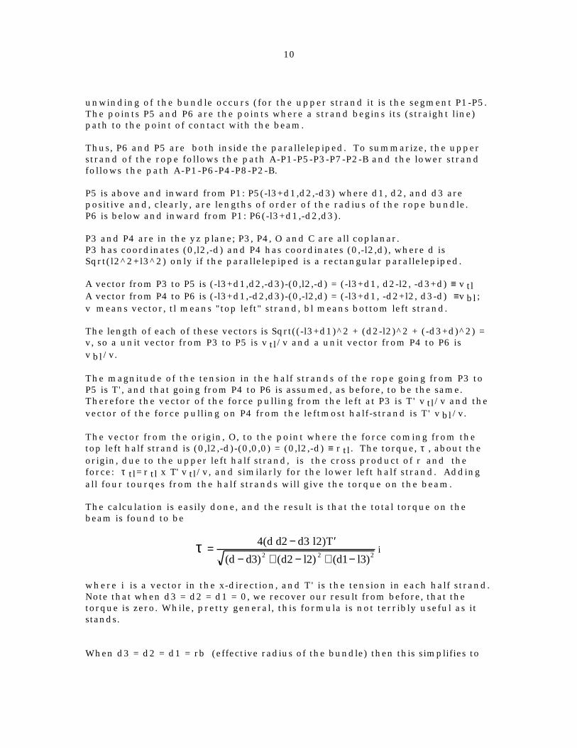
readily modeled as a circular helix. As shown in the diagram, a helix has alength L, in which n turns are made. The distance between the turns is thepitch, p, given by L/n. The radius of the helix is r0. Figure 8 shows a helixwith 8 turns.
P = L/8
L
n=8
r0
Fig. 8. The definition of the parts of a circular helix.
The length of the space curve for a helix with n turns is
S = 2 π n r02 + ( p / 2π )2
or
S = 2 π n r02 + (L / 2π n)2
When cocking the onager, we are increasing the turns in the helix by acertain amount, ∆n. For a first approximation, we can assume that the distanceA-P1 doesn't change during the cocking, and the cocking involves changingthe number of turns by one quarter of a turn. The length of the rope makingup the helix changes therefore changes during cocking by
∆S= π2
r02 + (L / 2π n)2
The rope has a characteristic stress-strain curve which can be used tocalculate the tension. In the linear part of the curve, the tension in the ropeis proportional to how much it has been stretched. That is, T = k ∆s, where k isan elastic constant for the rope. During the throw the helix unwinds by aquarter turn: ∆n = 0.25, and so the tension, and the torque, both decreaseduring the throw--but not to zero.Since

14
θ = 2π/n,
the dependence of the tension on the twist is
T = k θ r02 + (L / θ )2
It should be clear, however, that the bundle is made up of a number of ropeshaving various values for r0, and some number of different helices wouldneed to be considered to make the actual calculation of the overall tension, T.This would vary with the structure of the bundle, and how it relates to thebeam and the points of attachment. Various assumptions could be made for theconfiguration in thicker bundles, but the methodology for working out thetorques and tension would be basically unchanged.
Parallel Bundle modelAnother method of arriving at a twisted bundle involves starting as beforewith a parallel bundle of ropes. If there are four strands of rope, this is calledthe "4-stranded simple parallel bundle" and is a simple configuration. In thistype of skein the ropes are passed through their attachment in a parallelfashion under tension, then the beam is vertically inserted into the bundle,separating them into two pairs, without inducing any twist or crossing over ofthe strands. Then the onager is cocked by moving it into the horizontaldirection. This is depicted in a model in the next three pictures.
15
Fig. 9 Four parallel strands--no crossing of ropes or twists.
Fig. 10. The beam is inserted vertically separating the bundle--still no twists or crossing in the ropes. The beam is perpendicularto the plane of the yoke.

16
Fig. 11. The beam is cocked by moving it to be parallel to theyoke, imparting a twist in the ropes.
In the first of the pictures, we see that we can adopt a simple nomenclature forthe strands. There is an upper strand, in the front nearest the camera. Callthis the upper front strand, or "uf" strand for short. Similarly, there is a lowerfront, upper back, and lower back strand: lf, ub, and lb strands for short. Therope, which is actually one continuous piece enters from the left, then formsthe uf, ub, lf, lb strands successively. It is tied off under some initial tension atthe left capstan.
When the initial tension in the rope is high, we can observe experimentallythat the ropes do not slide along the beam as the beam is moved from thevertical to the horizontal position. It is as if the point of contact of the strandsto the beam are actually fastened to the beam. We will assume this to be thecase here. This may not be the case generally, for it depends upon the frictionbetween the beam and rope.
In the second picture, which has the beam inserted, the order of the strandsare not changed, but the front and back strands are separated in the center bythe height (2 l2) of the beam. This is farther than they were separatedinitially, so the ropes are under greater tension in the second picture than inthe first. To get the beam in, a wedge can be employed to widen the openingbetween the front and back strands.
In the third picture, in which the beam has been cocked by moving ithorizontally, the two nearest (front) strands have moved. The uf strandpasses over the beam and contacts the beam farther from the camera than thelf rope. Similarly, the ub strand contacts the beam farther from the camerathan the lb strand.

17
We are, of course, interested in the torque created by the cocking of the beam--the movement from the vertical to the back, horizontal position. Thereforewe need to get the position of each of the strands where they contact the beam,and where they are fixed at the points of attachment. We then form unitvectors along each of the four strands in the direction of the tension, andperform the cross product of the radius from the origin to the point ofattachment on the beam. The sum of the four tourques is the torque on thebeam. The torque will be along the x-axis.
Let A be the attachment at the left and B the attachment at the right. Theattachments are assumed to have a thickness 2 t so the central axes of the frontand back strands at the attachments are separated by t+s, where 2s is thediameter of the rope.
Two Stranded Parallel Bundle ModelThe simplest arrangement for the skein would involve just two parallelstrands, rather than the four illustrated in the pictures. This is not as strangeas it might seem--a thick complicated bundle can be usefully modeled as asingle thick rope, after all.
We set up a coordinate system with the origin in the center of the beam at 0,midway between the points of attatchment at A and B. Put the x axis throughA-O-B. The z-axis is up, perpendicular to the plane of the yoke. The y-axis isthrough O perpendicular to the xz plane. It is along the beam when it ishorizontal (cocked).
Using the same notation as before, we can write down the coordinates for thepoints of attachment and contact with the beam and calculate the torqueimparted to the beam.
The two strands (f=front, b=back)attached at the left have coordinates
Af = (-l1, t+s, 0);Ab = (-l1, -t-s, 0);
and the two back strands have coordinates at the points of attachment
B f = (l1, t+s, 0);Bb = (l1, -t-s,0).
The points of contact with the beam when it is cocked (i.e., horizontal) are
P f = (0, t+s, l2);P b = (0, -t-s, -l2).
The unit vector from the point of contact to the point of attachment at A forthe forward left (=L) strand is then
TfL=(Af-P f)/|Af-P f|
= (-l1/m, 0, -l2/m)

18
and similarly for the three other half strands, where the || signifiesmagnitude. The magnitude of the vector is
m = |Af-P f| = sqrt(l1^2 + l2^2).
The vector from the origin to the point of contact is just Pf for the front strandand Pb for the back strand. Then the total torque, τ , is the sum of torquescoming from each half-strand, so
τ = T (P f x (TfL +TfR) + P b x (TbL + TbR))
where T is the tension in each half-strand, all assumed to be equal. It is easy tosee by symmetry the two terms on the right are equal, so that this can besimplified to
τ = 2 T (P f x (TfL +TfR).
The sum of the tensions from the left and right strands is
T (T fL + TfR) = T (0, 0, -2 l2/m)
so, finally, the torque on the beam when it is cocked is the cross-product
τ = 2 T (0, t+s, l2) X (0, 0, -2 l2/m),
or, finally,
τ = (- 4 T l2 (t+s)/m, 0, 0),
which shows, as expected, that the torque vector is along the x-axis.
This result can also be readily seen by using the fact that there is a coupleinvolved: the two forces tf and tb are anti-parallel, with a magnitude 2 T xl2/m. The moment arm between them is 2(s+t).
The calculation can also be done using the Mathematica programminglanguage, and is shown for comparison in Appendix II. Comparing the twomethods should allow the reader to understand this language well enough tofollow along in the calculations for more complex cases to come.
The torque on the beam when cocked is proportional to T, and increases withthe beam thickness, both of which is reasonable. It is zero when t and s areboth zero, also as expected, based on our earlier discussion of the stringOnager.
It is also easy to show that the force pulling on the left attachment at A is
FA = 2 T (l1/m, 0, 0)

19
when the beam is cocked. This is only in, along the x-axis. For a fixed l2 thisincreases with l1, so it is better to design for a short distance between the yokearms: they will be less likely to break. Making the beam thicker ( thickness =2 l2) will also decrease the force tending to break the yoke.
Cocking the beam by moving it from the vertical to the horizontal directionwill change the lengths of the two strands, and therefore their tension willchange too. But how do we calculate the length of a half-strand? Do wemeasure along the center of the strand, or along the path that our tensiontakes? The two possibilities give slightly different answers, depending on sand t. There appears to be no easy way to resolve which is the betterapproximation.
It is slightly easier to calculate the latter possibility, and we'll use this method.The distance from the point of contact to the point of attachment when thebeam is cocked is
dc = sqrt((af-pf).(af-pf)) = sqrt(l1^2 + l2^2).
When the beam is upright, the point of contact is at (0, l2, 0), so thecorresponding distance is
du = sqrt(l1^2 + (l2 - s - t)^2),
which is slightly smaller. Therefore cocking the beam increases the tensionin the strands.
Given the initial tension in the strands before the insertion of the beam, andthe elastic constant for the rope allows one to readily calculate the tension ineach rope before and after cocking.
Torque as a function of angleIn order to get the dynamics of the Onager, we need to obtain the torque on thebeam when the beam is at arbitrary angle, θ, with respect to the horizontalaxis. When the beam is fully cocked, θ=0 and when it is vertical, θ is π/2.
At first we will concentrate our attention to the forward strand only. The backstrand analysis follows easily by symmetry. For the Two Stranded ParallelBundle Model, when the beam is upright, the point of contact of the forwardstrand with the beam is at pf = {0, l2, 0}. When the beam is horizontal, it is at{0, t+s, l2}. We need to get pf for an arbitrary angle. Start with the beam inthe vertical configuration. We have assumed that the point of contact doesn'tmove with respect to the beam. Therefore when we rotate the beam toward thehorizontal direction the point of contact will move along a circular path in theyz plane with the axis of rotation going through the origin of the coordinatesystem. The radius of the path will be l2. In the first part of the rotation,therefore, the coordinates of pf will be pf {0, l2 sin(θ), l2 cos(θ)}.
However, this cannot be the case for the entire range of θ because it doesn'thave the right value when theta is zero. A diagram shows that when the beam

20
is rotated, the strand comes to a point where it reaches straight across theyoke, and the axis of the strand has the equation y = t+s. The figure makes thisclear.
t
xy
z
l2O
1
2
3
4∆z
φ
θ
beam right edge
beam toppf(0,t+s,l2)
5
6
strand
pf{0,l2,0}
E
Fig. 13. The movement of the strand is hindered by the width ofthe point of attachment.
Fig. 13 shows the successive positions of the strand as the beam is rotated fromupright to horizontal. The start is at position 1 and the end position when thebeam is horizontal is at 6. At some point in the rotation, shown here as
21
position 4, the strand can't move any more to the left because of the thicknessof the point of attachment, t, and the finite radius of the strand, s. The point ofcontact therefore leaves the circle centered at O and travels upward as φincreases.
The upward travel starts when the point of contact is at E, and a little geometryreveals (love that phrase!) that it has coordinates
pf {0, l2(t+s)/(l2+s), l2*sqrt(1-((t+s)/(l2+s))^2)}; φ = φΕ
and the angle where this occurs is φΕ = arc cos((t+s)/(l2+S)).
The coordinates of the point of contact when φ > φΕ can be shown (moregeometry) to be
pf {0, t+s-s*cos(φ), l2/sin(φ)-(t+s- s cos φ)/tan(φ)}; φ > φΕ
Again, in the first part of the rotation the coordinates of pf will be
pf {0, l2 cos(φ), l2 sin(φ)}; φ < φΕ
where φ = π/2-θ. Using these expressions we can calculate the torque/tensionas a function of angle of rotation of the beam. The expressions are derived inAppendix II, and are
4 l2 s t Cos th
l12 l22 Cos th 2 s t l2 Sin th 2
,
for θ > θE
and for the hindered movement portion of the beam rotation,

22
2 s t Sec th
2 l2 s s Cos 2 th 2 s t Sin th
Sec th 2 l12 2 l22 2 l2 s 2 s2 2 s t t2
l12 2 l2 s 2 s2 2 s t t2 Cos 2 th
4 l2 3 s s t Sin th
s2 Sin 3 th s t Sin 3 th
l12 l22 Sec th 2 2 l2 s t Sec th Tan th
2 l2 s 2 s2 2 s t t2
2 s2 Sin th 2 s t Sin th Tan th 2 ,
0, 0
forθ < θE.
Fig. 13 shows the results for the torque/tension on the beam as a function of θfor the nominal case.
Fig. 13. The Torque over the tension as a function of beam angle.
In this graph, θ = 0 corresponds to the beam being horizontal and π/2 to itbeing vertical. The discontinuity in the slope of the torque corresponds towhere the strand "runs into" the point of attachment of the ends of the strand.

23
During the change in angle, of course, the tension is not a constant, so to getthe torque as a function of angle we need to multiply the torque over thetension by the tension. The tension is proportional to the fractional change inlength of a strand. This is given for one of the half-strands as
L(θ)/L = Sqrt[(pf(th)-af).(pf(th)-af)]/Sqrt[(pf(π/2)-af).(pf(π/2)-af)]
which looks like
Fig. 14. The fractional change in length for a half-strand of the 2stranded Onager.
The length changes by about 1.4%. The torque divided by the elastic constantthen looks like

24
Fig. 15. The torque divided by the elastic constant of the rope forthe 2 stranded Onager.
This is very similar in shape to the torque/tension plot for the nominal case.
The work involved in cocking the Onager by moving the beam from θ=π/2 toθ=θmin is given by the area under the curve between these limits.
The torque as a function of angle for multistranded parallel bundle models canbe derived by similar methods.
Four Stranded Parallel Bundle ModelThe next most complicated case for the parallel bundle model would have fourparallel strands. This introduces one qualitatively new element--the frictionbetween the strands. We will defer the discussion of this for now.
Then the eight half-strands at the points of attachment has coordinates, usingthe notation from before, of
Auf=(-l1,t+s,s)A lf=(-l1,t+s,-s)Aub=(-l1,-t-s,s)A lb=(-l1,-t-s,-s)
and
Buf=(l1,t+s,s)B lf=(l1,t+s,-s)Bub=(l1,-t-s,s)

25
B lb=(l1,-t-s,-s).
These are assumed not to move during the cocking or throw. The yoke isassumed to be rigid and the friction between the points of attachment and thestrands are very high. And the friction between adjacent strands will beassumed to be zero for now.
The points of contact of each strand with the beam when it is oriented alongthe y axis (i.e., beam is cocked) can be seen to be
P uf=(0,t+s,l2 )P lf=(0,t+3s,l2)
P ub=(0,-t-3s,-l2)P lb=(0,-t-s,-l2),
and the vectors from the origin to the point of application of the forces on thebeam are
r uf=P ufr lf=P lf
r ub=P ubr lv=P lb
The unit vector for the tension in each strand goes from the beam to the pointof attachment. There are eight half-strands: four go to the left and four to theright from the points of attachment. Use L and R to denote these directions.
Front half-strands:Tuf,L = T (P uf-Auf)/|P uf-Auf|
Tlf,L = T (P lf-A lf)/|P lf-A lf|Tuf,R = T (P uf-Buf)/|P uf-Buf|
Tlf,R = T (P lf-B lf)/|P lf-B lf|
and similarly for the back half-strands.
As in the two stranded parallel bundle model, the upper front strand ishindered in its movement by the width of the attachment, and since the lowerstrand is parallel to and touching the upper strand, its movement will behindered also.
We show in the Appendix III, using the Mathematica programming languagethe calculations of each of the torques about the origin and their sum. It is nothard to do this by hand, but Mathematica is quicker and more reliable.
As expected, the torque lies along the x-axis, as expected by symmetryconsiderations. The total torque divided by the tension in one of the strands(assumed for now to be the same in both) when the beam is cocked is now alittle more complicated:

26
4 l2 s s t
l12 l2 s 2
4 l2 s t s 3 s t
l12 4 s2 l2 s 2
where 2 l2 is the height of the beam, s is the radius of the strand, and 2t is thethickness of the points of attachment. In the limiting case when s=t=0, thetorque is also zero, as expected. This verifies our notion that the essentialelement of the model is in the finite diameter of the ropes.
The first term in the torque comes from the uf and lb strands, and the secondfrom the lf, ub strands.
A comparison can be made between this two stranded and the four strandedmodels using these formulas.
For the limit when t is zero, l1=10, l2=2, say, and the s is small, the ratio is seento be 2., as expected because the strand numbers is in the same ratio. When,say l1=10, l2=2, t=.5 and s=.5, then the ratio of the two torques is 2.23. Thismeans that the torques are not simply proportional to the number of strands--it is a function of rope radius too.
The angular dependence of the torque/tension for this model is qualitativelysimilar to that for the 2 stranded parallel bundle model--it has two regions thatare continuous, etc.
The General Parallel Bundle Model as a Function of AngleIt is possible to carry these calculations further into a general treatment forthe n-stranded parallel bundle model as a function of angle. This is done inAppendix IV, where the calculations are illustrated for the 4 stranded parallelbundle. This set of calculations could also serve as a starting point for adetailed consideration of more complex configurations of the skein, in which,for example, there are layers of parallel strands. This has not been done yet.
One point to make about the parallel bundle model is that the tension in eachstrand may differ because each of the strands stretch by different amounts.Thus, there are two possibilities to consider.
In the first, which we may denote as the "fixed ends" parallel bundle model,the attachment points of each strand is assumed not to move during thecocking. It would be as if each strand were individually fastened to its point ofattachment. The tension in each strand could differ, according to how muchtension is initially applied and how much each is stretched during themovement of the beam.
In the second model, which may be called the "free ends" model, each of thestrands move freely through the points of attachment during the movement ofthe beam, and the tension in all of the strands are the same.
27
Because the hard part of the calculation for the torque actually only calculatesthe torque/tension for each strand, it is easy to calculate the total torque foreither of the two models, and this is also illustrated by way of an example inAppendix IV.
At this point in our investigation of the Onager, it is not possible to say wheneither of the models apply. Possibly the truth is somewhere between these twoextremes, and it would be best to perform both calculations and average theresults in some way.
One important consideration in connection with the two models is that theygive different predictions on whether or not the rope will break orpermanently deform during the rotation of the beam. When s and t arerelatively large, the length changes are greater, and may exceed the maximumstrain that the rope can sustain without permanent deformation or breaking.In the design of any Onager, it is a fairly simple matter to calculate the lengthchanges for either the fixed or free end models, and compare them to theallowed length changes for the material of choice. Nothing is morefrustrating than to make an Onager, string the strands, and have it breakduring cocking!
General Rules for Parallel Bundle ModelsOne important observation to note in all of these models, is that when thedistance between the attachment points (2 x l1) increases, the torquedecreases, because l1 appears only in the denominators. Also, with increasingl1, the force tending to break the yoke increases too. Other things beingequal, it is better to keep the yoke breadth small for a good design.
For a given tension, rope with a big diameter (2 x s) will give better results. Athick (2 x t) point of attachment gives better results, but note that the analysisimplicitly assumed that s+t <l 2: the rope is in contact with the beam during therotation of the beam. Finally, for any l1, the torque is greater for thicker (2 xl2) beams. For small s, the torque is proportional to the number of strands, butrises faster than linearly for non-zero s and/or t.
Tensioning the Ropes and Friction at Points of AttachmentThe methods available to apply the tension in the ropes during the stringingof the bundle and the problems associated with this are topics which areimportant for any practicing Onager engineer. A lot of work is required toaccomplish it, and it is easy to go wrong. It will be clear from our discussionthat much remains to be discovered.
Consider first the parallel bundle model. Normally, one does not use individualropes tensioned between the points of attachment at the yoke, but rather onecontinuous rope that goes over a cylindrical bar of metal in the capstan(s),snaking between these supports a certain number of times, which is then tiedoff somehow at one end. There are lots of ways to actually generate thisconfiguration.

28
Usually, the supporting fixture where the ropes make their turn at the pointsof attachment have a straight cylindrical cross-section, though we should,perhaps, keep an open mind about this.
Consider the generalized configuration in Fig. 16, in which a rope passes over
T
T0
∆θ
Fig. 16. A rope contacting a rough cylinder through an angle ∆θ.The tensions T and T 0 in the two segments of the rope aredifferent.
a rough cylindrical surface, representing the supporting fixture. Thecylinder is fixed so it cannot move, and the rope is held in static equilibriumby two tensions, T and T0. The rope is in continuous contact with thesupporting fixture between the points P1 and P2, which subtends an angle atthe axis of the cylinder through an angle ∆θ. The static coefficient of frictionbetween the rope and the supporting fixture is taken to be µ.
We all know from experience that if we make a couple of wraps around a pole,we can support a much greater load than without it. This is how one "brakes"moving heavy loads. Evidently the two tensions T and T0 are not the same. Infact, it can be shown that the relationship between the two is
T = T0 e µ∆θ
This shows that the relationship is exponential in the friction coefficient andthe subtended angle. For example, if we take just two turns around thecylinder, ∆θ would be 4 π, and if the coefficient of friction is, say, 0.5, then theratio of the two tensions is e 2π = 535. This is pretty big!
For the case of the Onager, each turn in the rope would have ∆θ = π. Passingthe rope through two of these turns will give a ratio in the tensions, then, of

29
T/T0 = e µπ e µπ = e 2µπ
In the case of passing the rope through n turns would give a ratio of theinitial and final strands of rope,
T/T0 = e µ n π.
So what happens when you just try to thread all of the ropes over theirsupporting fixtures a few times, then pulling on the rope in preparation totying off the end? Well, the first strand in your hand would have a tension, T0,
the next one T0 e - µ π and the next one would have a tension T0 e - µ 2 π and so
on. Suppose the friction coefficient is 0.5, so e µπ = 4.8. Then after only 3turns, giving 4 strands, the tension in the farthest strand is only about 1% ofthe tension of the one in your hand! This would mean, of course, a greatdecrease in the efficiency of the bundle. The first strands would contain verylittle energy.
One way to avoid the problem would be to make the friction between the ropeand the supporting fixture vanish by using a bearing of some kind. Anotherpossibility would be to somehow clamp each rope to the supporting fixtureafter it is threaded and tensioned then thread, tension and clamp the nextstrand, and so on. A third alternative is to use individual ropes in each strand,tensioning and tying them off separately. This would have the advantage thatropes of different elasticity and diameters might be used, tailoring theirproperties to their relative position in the bundle. Exact ly how this problemwas solved in the historical Onager is unknown.
In the twisted model bundle, this problem is largely avoided because the ropeis threaded through the attachments and then the tension is applied to all ofthem as a group by twisting the capstans. Each strand will initially havedifferent, relatively low, tensions at the start of the twisting. If the bundle ishighly twisted, each strand will probably have more or less the same tension.The details of this situation are, however, complicated when considered indetail.
Clearly, our treatment of this leaves some room for improvement.
Internal friction in the BundleAs we have seen, during the movement of the beam, the strands changelengths by different amounts. This means that there will be some frictionbetween adjacent strands, provided there is a force tending to draw themtogether. The situation will be different for the different models.
In the parallel bundle model, we have assumed that the points of contact of thestrands with the beam do not move. Friction is very high there, the same as ifthe strands are fastened to the beam by some sort of fastener. The model alsoassumes that the point of attachments are fixed and the strands are not twistedover one another.

30
A critical assumption in this model, which is worth reiterating, is that thevector, T, representing the tension in a strand goes from the center of thestrand at the attachment point to the point of contact of the strand with thebeam. The line of contact between adjacent strands in the bundle is different,however. The line of contact between the strands terminates at the point ofcontact of the next higher strand, but it starts at a point displaced in the z-direction by s, the radius of the strand. Call this (unit) vector line of contact,between these two points, R . These vectors are different, so the normal forcebetween the strands at the line of contact is the cross product T x R . Thefriction between the two strands is proportional to this normal force, with theconstant of proportionality being the coefficient of friction.
The friction between the two strands is then µ T x R, where µ is thecoefficient of (kinetic) friction of the material in the strands. The net tensionin a strand that is used to create the torque is then
Teff = T- µ T x R/2,
where the factor of two enters because two strands are involved.
If the strands changed lengths by the same amounts during the movement ofthe beam, there would be no relative movement between adjacent points onthe strands and so no work would be expended. If the difference in length ofthe two strands changed by an amount dL , the amount of work would expendedwould be
dW = (µ T x R) .dL,
Integrating over the length of each strand gives, finally, the work expendedin friction between the two strands i, and i+1 during the cocking as
Wi,i+1 = (µ T x R) .( ∆L i+1 - ∆L i ).
where ∆L i is the length change in the ith strand during cocking. To get thetotal energy lost, we need to sum this over all of the lines of contact betweenadjacent strands. If we have N strands, there are N-1 of them.
During the throw, energy is also lost to friction, and the amount lost dependsupon the position (angle, θ) of the beam. For obtaining the dynamics of thebeam, Teff summed over all of the strands, should be used, rather than T.
Onager efficiencyA definition of the range efficiency of the onager may be easily derived.During multiple throws of the Onager, the beam is cocked by being broughtfrom a roughly vertical position to a roughly horizontal one. The torque onthe beam about its axis due to the twisting of the skein varies with the angleand is rather easily measured or (approximately) calculated. If the torque, τ asa function of the rotation angle, θ, is known, then the work, E, expended onthe bundle is given by

31
E = τ (θ )θ i
θ f
∫ dθ
During the throw, this energy is partly transferred into the projectile of massm2, and partly into the rotation of the beam of mass mb, and into friction, andother imperfections. If none of the energy went into the beam and none intoheat, and the projectile left the sling (at 45° with respect to the horizontal),formaximum distance, it would go a distance
Rm = 2 E/(m2 g).
Any real Onager will throw the projectile a distance, Rexp, different from thisbecause of various sources of friction.
The measured range efficiency for a real Onager would then be
Reff = Rexp/Rm.
This has apparently never been measured for any actual Onager.
A theoretical maximum efficiency for a design would involve calculating theintegral exactly to get Rm, and then carrying out a simulation of the dynamicsof the throw, using a non-zero value for the mass of the beam to get atheoretical maximum range of Rth. The range efficiency for the design wouldthen be
Reff = Rth/Rm.
Energy in the BundleThe energy in the bundle available for rotating the beam is a key parameterin designing the Onager. This can and should be understood and calculated foryour design. This requires only some pretty elementary considerations of thegeometry and material used to make the bundle.
First, whatever material is used, we must understand that there is a maximumstrain (fractional length change) that it can withstand without permanentlydeforming or breaking. Our design should not exceed this maximum.
At this maximum strain, the strength of a rope is called its maximum workingstrength. The strength of a rope is proportional to the cross-sectional area ofthe rope.
If the rope is elastic and below the elastic limit, the energy, E, per unit volume,V, of rope contained in a rope with a strain of dl/l and a stress σ is

32
E /V = (dl/l) * σ/2
Here stress is measured in N/m^2 or Pa, in the metric system, and psi in theAmerican system. The strain is dimensionless because it is a fractional lengthchange.
In order to look at the trade-offs involved in selecting a material for the ropein the bundle, one has to survey the properties of ropes made from variousmaterials, with different braids, from different manufacturers, and so on. Ourinitial attempt at this exercise looked at some specifications of different ropesfrom two websites (4,5). I looked for strengths of rope that were 1/2 inch indiameter, and converted that to a stress (strength/area). I then calculated theenergy inone meter of this rope when stretched to the maximum (tabulated) strain,using the formula above. The table shows the results.
strain at strength of str./area E for 1 m long E for 1 mmaterial max stress 1/2" dia at max strain at 2% str.
lbs N/cm^2 MJ MJnylon double braid 0.32 8500 7500 0.61 0.038nylon 8 stranded 0.32 6500 5700 0.46 0.029polyester double braid 0.17 8200 7200 0.31 0.036polypropylene 12 strand 0.2 4900 4300 0.22 0.022manila 0.11 3300 2900 0.08 0.015steel 0.02 2000 1760 0.01 0.010kevlar K 0.01 15000 13200 0.03 breaks
Clearly, a well-designed bundle has the maximum energy per unit volume ofrope. The strain in the rope has to be below the maximum, but as high aspossible. Looked at in this way (respective of cost) nylon double braid appearsto be the best candidate and is definitely superior to polypropylene. Steelcable is not even in the running. Kevlar, though very strong, is also ruled outbecause its maximum strain is so low. The table can be used to quickly estimatethe values for other sizes of ropes: the energy E is proportional to the lengthand directly proportional to the square of the diameter of the rope.
For a parallel bundle model, we can use the energy formula in a verystraightforward way. If the distance between attachments is 2 l1 and there aren strands, each with a diameter 2 s, then we have a volume of rope (neglectingthe small length at the attachment), for the parallel bundle model, givenapproximately by
V = 4 sqrt(l12 + l2 2 ) n π s2
so the energy in the bundle, using the free ends, parallel bundle model is
E = 2 n π s2 (dl/l) sqrt(l12 + l2 2 ) σ.
33
As an example, take a four stranded parallel bundle with s = 0.5 cm, l1= 5 cm, l2= 1 cm, made from nylon with a stress at failure of 57 MPa, and a strain of 0.32it would have an energy of
E = 8 π x 0.0052 x 0.32 x sqrt(0.052 + 0.012) x 57 x 106 =
648 J
This assumes all of the strands are strained almost to breaking, equally.
The range of projectile with a velocity v at 45° with respect to the horizontal isv2/g, where g is the acceleration due to gravity. If all of the energy E goesinto kinetic energy of a projectile having a mass m, therefore, the range willbe
R = 2 E/(m g).
Therefore if all of the energy is deposited into a projectile (i. e., efficiency =100%, no friction) having a mass, say, of 1000 g, that fires off at 45°, it will go
R = 2 x 648/(1 x 9.8) = 132 m,
which is quite respectable. However, as we have showed in the Appendix IVfor this model (having the same l1, l2 , s and t) the strains when cocked ineach of the half-strands varied from 0.014 up to 0.27 with an average of about0.10. This alone decreases the range by a factor of about 0.1/0.32 to 41 m.
The coupling efficiency between the bundle and the projectile will besomething less than 100%, mostly because the bundle must accelerate the beamto some high rotational velocity when the projectile leaves the sling, whichleaves some time before the beam is upright. Inefficiency due to this might beguessed to be ( a simulator can provide this number) on the order of 0.5, so wemight expect a range for this Onager on the order of 20 m. The overallefficiency of this design would then be on the order of 0.3*0.5 or 15%.
If the overall efficiency of the Onager is ε, then the range will be
R = (2 ε n π s2 (dl/l) l1 σ)/(m g).
This formula can be used for measuring the efficiency of a real Onager:measure the range and solve for the efficiency. This has not been done so far,apparently, by any Onager engineer.
Back of the Envelope DesignIn the parallel bundle models, the torque is zero when θ = 90°, and somemaximum torque tc when cocked.

34
If the torque is linear with theta, then the integral can be approximated as thearea of a triangle, so
E = π τc/4.
Combining these relations shows that an estimate for the range would be
Rest ≈ π τc/(2 m2 g),
where g is the acceleration due to gravity.
This formula can serve as a starting point for a first approximation for adesign. As an example, suppose you want to throw a 2 kg pumpkin 100 m, thenyou need a design that can produce a torque of about
τc ≈ (2/π) m2 g Rest = 2 kg x 9.8 m/s2 x 100 m
τc ≈ 2000 kg m2 s-2 = 2000 N m.
Allowing for various inefficiencies in the design, one might want, say, twicethis much, or 4000 N m. Try the very simplest model for a start: the twostranded parallel bundle model, which has
τc = 4 l2(s + t)
l12 + l2 2 T
Starting with thickness of the attachment 2t = 0, and with attachment pointseparation of, say 2 l1 = 50 cm and beam thickness 2*l2 = 10 cm gives a required
s T =l12 + l22
4 l2τc =
0.252 +.0252
4 0.05τc = 1.3 τc ≈ 5200 N m
So if the rope has a radius of s = 1 cm, then we'd better have one that cansustain a tension of 520,000 N without breaking. A useful conversion factorfor the Americans is that 1 N is 0.2248 pounds of force. So we'd need a rope thatcan hold about 120,000 pounds. This would be an awful strong rope! Betterassume a bigger rope, with more strands.
Suppose our nylon rope 0.5 in in diameter has a working strength of about4000 pounds (it is a little old), so s T for the rope is about 0.5 x 2.54 cm/in x 4000p/0.2248 = 225 N m which is still off from the required 5200 Nm by a factor of23.
35
Let's try a model with t=s, and 2 l1 decreased to 30 cm. Then s T would berequired to be about 0.4 τc = 1600 N m, which is better by a factor of 3.25, and 8strands of nylon rope 0.5 in in diameter would about do it.
ConclusionsTwo basic models for the rope bundle have been described. The parallelbundle model, and highly twisted model with two variants, "open" and "closed"are described. The geometry involved in the models are described in terms ofthe dimensions of the parts, and expressions for the torque and tension in astrand as a function of angle are worked out.
By using some elementary physical reasoning, we have been able to showwhere some of the guidelines for a good Onager design comes from: the key isto consider the elementary strand in the bundle as having a non-zero radius.The principle resulting guideline is to make the yoke braces close together,the beam, points of attachment, and the rope should all be thick. Some simpledimensional analysis showed that the energy in the rope scales as the thirdpower of its diameter, and the thickness of the beam should be scaled as thefirst power of the skein (rope) diameter.
Because there is a limit in the travel of the strands in the parallel bundlemodel during cocking, the torque-cocking angle graph has two segments to it,which would need to be incorporated in any accurate dynamical simulations ofthis class of models.
A method for measuring the experimental range efficiency for a real Onagerhas been obtained, and a method to calculate a theoretical range efficiency forsimulated Onagers has also been described. A method for starting a back-of-the envelope design of the bundle based on bundle energetics was illustratedby an example. It appears that nylon is probably the best available materialfor the rope.
Much work remains to be done to improve our understanding of Onagerdesign, but a good start has been made.

36
References1. Marsden, E. W., Greek and Roman Artillery-Technical Treatises, OxfordUniversity Press, Oxford, England, 1971.
2. Payne-Gallway, Sir Ralph, The Crossbow, The Holland Press, London,England, 1958.
3. Siano, D. B., Will It Break? , http://members.home.net/dimona/ , 2000.
4. http://www.usrigging.thomasregister.com
5. http://www.wallrope.com
37

38
Appendix I
The TorqueThe magnitude of the torque of a force about a given axis of rotation is definedas the product of the magnitude of the component of the force in a planeperpendicular to the axis by the lever arm of the force relative to the givenaxis. The lever arm is the perpendicular distance from the axis of rotation tothe line of action of the force. This will be clear by considering the diagram
BO
F
A
C
Fig. A1. The definition of torque, using a door fastened by a hingeat O.
The diagram shows a door fastened to a fixed wall by a hinge at O that allowsrotation about an axis through O perpendicular to the plane of the paper. Weapply a force, F, to the other end of the door at some angle with respect to thedoor. The line of action of the force is then A-B, and the lever arm is thelength of O-C, which we can call L. The magnitude of the torque is then Ltimes F. It has dimensions of length times force, N m in the metric system, orft p in the English system.
Note that if the Force were perpendicular to the door, the torque would bemaximal, because the line of action of the force is as big as it can get. And if Fwere along the door, the line of action, and hence the force, would be zero.Note that we have only considered a force F that is in the plane of the paper.If the force were applied at an angle to the plane of the paper, we would onlyconsider the component of the force in the plane of the paper.
So far we've only discussed the magnitude of the torque. But torque is a vector.It's direction in the case shown is perpendicular to the paper, coming out ofthe paper.
A little more sophisticated definition of torque is shown in Fig. 2 whichrepresents a force, F, being applied to a body at a point of application, A .Think of a string attached at A being pulled with a force F.
39
Fr
A
O
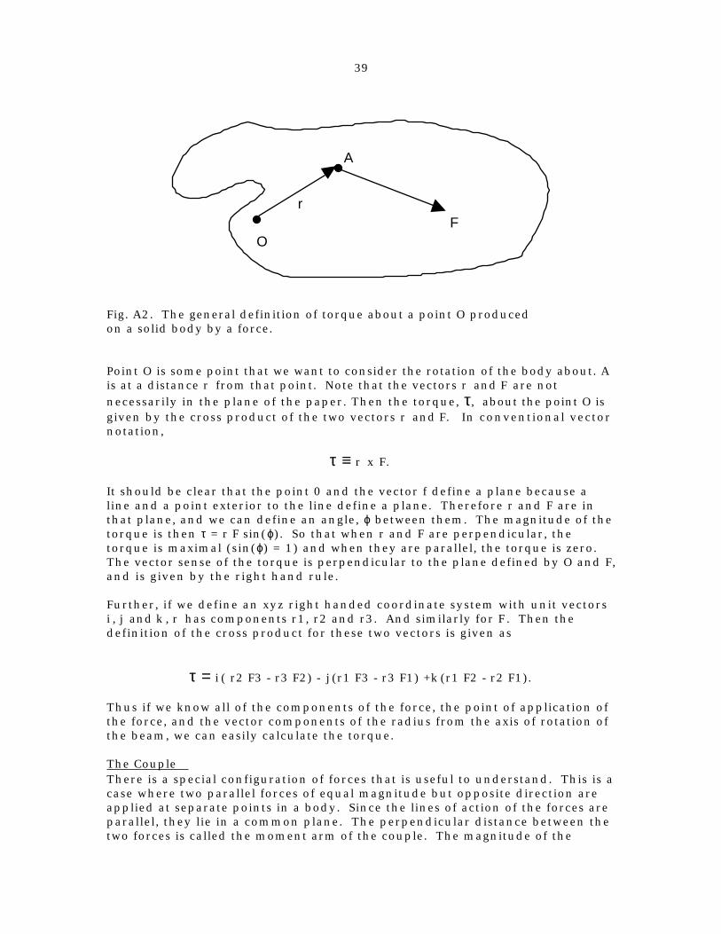
Fig. A2. The general definition of torque about a point O producedon a solid body by a force.
Point O is some point that we want to consider the rotation of the body about. Ais at a distance r from that point. Note that the vectors r and F are notnecessarily in the plane of the paper. Then the torque, τ, about the point O isgiven by the cross product of the two vectors r and F. In conventional vectornotation,
τ ≡ r x F.
It should be clear that the point 0 and the vector f define a plane because aline and a point exterior to the line define a plane. Therefore r and F are inthat plane, and we can define an angle, ϕ between them. The magnitude of thetorque is then τ = r F sin(ϕ). So that when r and F are perpendicular, thetorque is maximal (sin(ϕ) = 1) and when they are parallel, the torque is zero.The vector sense of the torque is perpendicular to the plane defined by O and F,and is given by the right hand rule.
Further, if we define an xyz right handed coordinate system with unit vectorsi , j and k , r has components r1, r2 and r3. And similarly for F. Then thedefinition of the cross product for these two vectors is given as
τ = i ( r2 F3 - r3 F2) - j (r1 F3 - r3 F1) +k (r1 F2 - r2 F1).
Thus if we know all of the components of the force, the point of application ofthe force, and the vector components of the radius from the axis of rotation ofthe beam, we can easily calculate the torque.
The CoupleThere is a special configuration of forces that is useful to understand. This is acase where two parallel forces of equal magnitude but opposite direction areapplied at separate points in a body. Since the lines of action of the forces areparallel, they lie in a common plane. The perpendicular distance between thetwo forces is called the moment arm of the couple. The magnitude of the
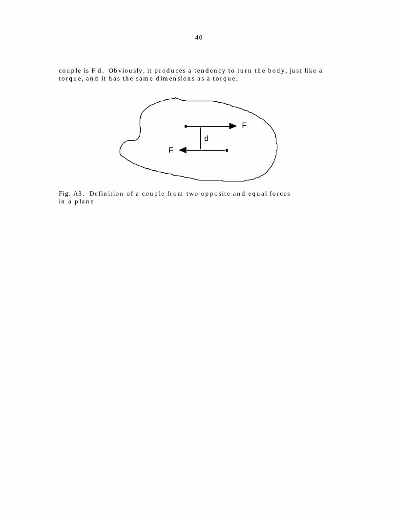
40
couple is F d. Obviously, it produces a tendency to turn the body, just like atorque, and it has the same dimensions as a torque.
d
F
F
Fig. A3. Definition of a couple from two opposite and equal forcesin a plane

41
Appendix II
(* 2 stranded parallel bundle Onager*)(* Donald Siano*)(* May 6 2001 *)(* get torque on Onager beam for general angle of beamwith horizontal, theta*)
(* u means upperl means lowerf means forwardb means backa is attachment at leftb is attachment at rightp is point of contact of strand
2t is thickness of attachment2s is diameter of single strand*)
(* 2 strands attached at left:*)af={-l1,t+s,0};ab={-l1,-t-s,0};
(* 2 strands attached at right:*)bf={l1,t+s,0};bb={l1,-t-s,0};(*first study cocked case, then the uprightcase, then general case:*)
(* points of contact with beam, cocked;*)
pf={0,s+t,l2};pb={0,-s-t,-l2};
(* unit vectors in direction of tension in indicated half-strand*)TfL=Simplify[( -pf+af)/Sqrt[(pf-af).(pf-af)]]TfR=Simplify[(- pf+bf)/Sqrt[(pf-bf).(pf-bf)]]

42
TbL=Simplify[(- pb+ab)/Sqrt[(pb-ab).(pb-ab)]]TbR=Simplify[(- pb+bb)/Sqrt[(pb-bb).(pb-bb)]]
TfL+TfR+TbL+TbR (*check*)
{-(l1/Sqrt[l1^2 + l2^2]), 0, -(l2/Sqrt[l1^2 + l2^2])} {l1/Sqrt[l1^2 + l2^2], 0, -(l2/Sqrt[l1^2 + l2^2])} {-(l1/Sqrt[l1^2 + l2^2]), 0, l2/Sqrt[l1^2 + l2^2]} {l1/Sqrt[l1^2 + l2^2], 0, l2/Sqrt[l1^2 + l2^2]}{0, 0, 0}
(*look at signs for TfL: force on beam at pf from the front strand is to leftand down, which are correct and sum of forces on the beam whencocked is zero*)(* the radius from origin to point of action of tensions*)rf=pf;rb=pb;
(* resultant for the dimensionless tension of the two fronthalf-strands*)tf=TfL+TfR(* and two back strands:*)tb=TbL+TbR
{0, 0, -((2*l2)/Sqrt[l1^2 + l2^2])}{0, 0, (2*l2)/Sqrt[l1^2 + l2^2]}
(* this shows that the front strand pushes only down, and the back strand pushes only up, which is correct*)(* torque on the beam when cocked:*)tk1=Simplify[CrossProduct[rf,tf]+CrossProduct[rb,tb]]
{-((4*l2*(s + t))/Sqrt[l1^2 + l2^2]), 0, 0}
(* this is in the -x-direction, which is correct*)TfLTfR

43
{-(l1/Sqrt[l1^2 + l2^2]), 0, -(l2/Sqrt[l1^2 + l2^2])}{l1/Sqrt[l1^2 + l2^2], 0, -(l2/Sqrt[l1^2 + l2^2])}
TfL+TfR+TbL+TbR
{0, 0, 0}
(*for the upright beam,*)(* points of contact with beam, cocked*)pf={0,l2,0};pb={0,-l2,0};(* unit vectors in direction of tension in indicated half-strand*)TfL=Simplify[( pf-af)/Sqrt[(pf-af).(pf-af)]];TfR=Simplify[( pf-bf)/Sqrt[(pf-bf).(pf-bf)]];TbL=Simplify[( pb-ab)/Sqrt[(pb-ab).(pb-ab)]];TbR=Simplify[( pb-bb)/Sqrt[(pb-bb).(pb-bb)]];
(* the radius from origin to point of action of tensions*)
rf=pf;rb=pb;
(* resultant for the dimensionless tension of the two fronthalf-strands*)tf=TfL+TfRtb=TbL+TbR
{0, (2*(l2 - s - t))/Sqrt[l1^2 + (-l2 + s + t)^2], 0}{0, (2*(-l2 + s + t))/Sqrt[l1^2 + (-l2 + s + t)^2], 0}
tk1=Simplify[CrossProduct[rf,tf]+CrossProduct[rb,tb]](* should be zero for upright beam*)
{0, 0, 0}
(*Now for the general case where beam is at angle th,*)
(* points of contact with beam, while y < t+s *)

44
pf={0,l2 Sin[th],l2 Cos[th]};pb={0,-l2 Sin[th],-l2 Cos[th]};(* unit vectors in direction of tension in indicated half-strand*)TfL=Simplify[( pf-af)/Sqrt[(pf-af).(pf-af)]];TfR=Simplify[( pf-bf)/Sqrt[(pf-bf).(pf-bf)]];TbL=Simplify[( pb-ab)/Sqrt[(pb-ab).(pb-ab)]];TbR=Simplify[( pb-bb)/Sqrt[(pb-bb).(pb-bb)]];
(* the radius from origin to point of action of tensions*)
rf=pf;rb=pb;
(* resultant for the dimensionless tension of the two fronthalf-strands*)tf=TfL+TfRtb=TbL+TbRtk1=Simplify[CrossProduct[rf,tf]+CrossProduct[rb,tb]](* torque is Tension times this:*)
{0, -((2*(s + t - l2*Sin[th]))/ Sqrt[l1^2 + l2^2*Cos[th]^2 + (s + t - l2*Sin[th])^2]), (2*l2*Cos[th])/Sqrt[l1^2 + l2^2*Cos[th]^2 + (s + t - l2*Sin[th])^2]}
{0, (2*(s + t - l2*Sin[th]))/ Sqrt[l1^2 + l2^2*Cos[th]^2 + (s + t - l2*Sin[th])^2], -((2*l2*Cos[th])/Sqrt[l1^2 + l2^2*Cos[th]^2 + (s + t - l2*Sin[th])^2])}
{(4*l2*(s + t)*Cos[th])/Sqrt[l1^2 + l2^2*Cos[th]^2 + (s + t - l2*Sin[th])^2],
0, 0}
(* calculate length of a half-strand*)Simplify[(af-pf).(af-pf)]
l1^2 + l2^2*Cos[th]^2 + (s + t - l2*Sin[th])^2

45
Plot[Simplify[(af-pf).(af-pf)]/.{l1->10,l2->2,s->.5,t->.5},{th,0,Pi/2}]
0.25 0.5 0.75 1 1.25 1.5
102
103
104
105
(*checks:*) tk1/.th->Pi/2
{0,0,0}
tk1/.th->0{(4*l2*(s + t))/Sqrt[l1^2 + l2^2 + (s + t)^2], 0, 0}
(* look at a typical case:*)tkp=tk1/.{l1->10,l2->2,s->.5,t->.5}{(8.*Cos[th])/Sqrt[100 + 4*Cos[th]^2 + (1. - 2*Sin[th])^2], 0, 0}0}
Plot[tkp[[1]],{th,0,Pi/2}]
0.25 0.5 0.75 1 1.25 1.5
0.2
0.4
0.6
0.8

46
(*for the general case where beam is at angle th,*)(* points of contact with beam, while y<t+s*)(*phe=ArcSin[(Sqrt[l2^2-(t+s)^2])/l2];*)phe=.;pf={0,t+s,-(1/Tan[phe])*(t+s-l2* Cos[phe])+l2*Sin[phe]}/.phe->Pi/2-thpb={0,-t-s,(1/Tan[phe])*(t+s-l2* Cos[phe])-l2*Sin[phe]}/.phe->Pi/2-th
(* unit vectors in direction of tension in indicated half-strand*)TfL=Simplify[( pf-af)/Sqrt[(pf-af).(pf-af)]];TfR=Simplify[( pf-bf)/Sqrt[(pf-bf).(pf-bf)]];TbL=Simplify[( pb-ab)/Sqrt[(pb-ab).(pb-ab)]];TbR=Simplify[( pb-bb)/Sqrt[(pb-bb).(pb-bb)]];
{0, s + t, l2*Cos[th] - (s + t - l2*Sin[th])*Tan[th]}{0, -s - t, -l2*Cos[th] + (s + t - l2*Sin[th])*Tan[th]}
pf/.th->0pb/.th->0 (* checks ok*){0, s + t, l2}{0, -s - t, -l2}
(* the radius from origin to point of action of tensions*)
rf=pf;rb=pb;
(* resultant for the dimensionless tension of the two fronthalf-strands*)tf=TfL+TfRtb=TbL+TbRtks=Simplify[CrossProduct[rf,tf]+CrossProduct[rb,tb]](* torque is Tension times this:*){0, 0, (2*Sec[th]*(l2 - (s + t)*Sin[th]))/ Sqrt[l1^2 + Sec[th]^2*(l2 - (s + t)*Sin[th])^2]}
{0, 0, (2*(-l2*Sec[th] + (s + t)*Tan[th]))/ Sqrt[l1^2 + (l2*Sec[th] - (s + t)*Tan[th])^2]}

47
{-((4*Sqrt[2]*(s + t)*Sec[th]*(-l2 + (s + t)*Sin[th]))/ Sqrt[Sec[th]^2*(l1^2 + 2*l2^2 + s^2 + 2*s*t + t^2 + (l1^2 - (s + t)^2)*Cos[2*th] - 4*l2*(s + t)*Sin[th])]), 0, 0}
phe=ArcSin[(Sqrt[l2^2-(t+s)^2])/l2]/.{l1->10,l2->2,s->.5,t->.5}1.0472
(* check alternate form*)phe=ArcCos[(t+s)/l2/.{l1->10,l2->2,s->.5,t->.5}]1.0472
the=Pi/2-phe0.523599
(* the two sections*)tkps=tks1/.{l1->10,l2->2,s->.5,t->.5};tkpe=tk1[[1]]/.{l1->10,l2->2,s->.5,t->.5};
(* Now combine the two sections into one function and plotit*)tkgen[th_]:=If[th<the,tkps,tkpe]Plot[tkgen[th],{th,0,Pi/2},PlotLabel->"l1->10,l2->2,s->.5,t->.5", AxesLabel->{"\[Theta]","torque/tension"}]

48
0.25 0.5 0.75 1 1.25 1.5
0.2
0.4
0.6
0.8
torque tension l1 10,l2 2,s .5,t .5
checks: tk1 . th Pi 2
0, 0, 0
tk1 . th 0
4 l2 s t
l12 l22 s t 2, 0, 0
look at a typical case:tkp tk1 . l1 10, l2 2, s .5, t .5
8. Cos th
100 4 Cos th 2 1. 2 Sin th 2, 0, 0
49
Appendix III
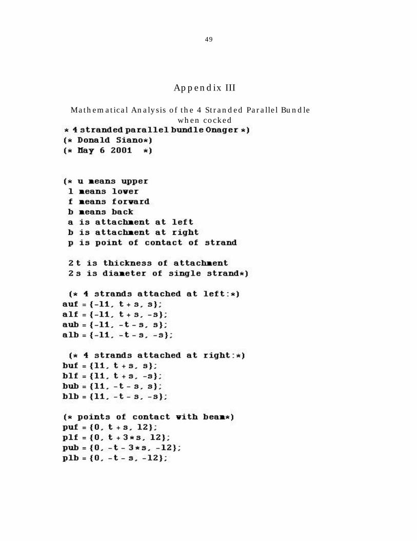
Mathematical Analysis of the 4 Stranded Parallel Bundlewhen cocked

50
unit vectors in direction of tension in indicated half strandTufL Simplify puf auf Sqrt puf auf . puf auf ;TlfL Simplify plf alf Sqrt plf alf . plf alf ;TufR Simplify puf buf Sqrt puf buf . puf buf ;TlfR Simplify plf blf Sqrt plf blf . plf blf ;
TubL Simplify pub aub Sqrt pub aub . pub aub ;TlbL Simplify plb alb Sqrt plb alb . plb alb ;TubR Simplify pub bub Sqrt pub bub . pub bub ;TlbR Simplify plb blb Sqrt plb blb . plb blb ;
the radius from origin to point of action of tensionsruf puf;rlf plf;rub pub;rlb plb;
resultant for the tension of the two front strandstuf TufL TufRtlf TlfL TlfR

51

52
total torquetktot tk1 tk2
4 l2 s s t
l12 l2 s 2
4 l2 s t s 3 s t
l12 4 s2 l2 s 2, 0, 0
this is only in the x direction, as expected
tktot . s 0, t 0should be 0,0,0 to agree with earlier results
0, 0, 0
case when t 0:tktot . t 0
4 l2 s s
l12 l2 s 2
4 l2 s 3 s2
l12 4 s2 l2 s 2, 0, 0
suppose l1 l0, l2 5 t .5 and s varies up to 10this is a plot of torque T vs s
tk10 tktot 1 . l1 10, l2 2, t .5 ;Plot tk10 , s, 0, 1.5 ,PlotLabel "torque T vs s when l1 l0, l2 2, t .5"
0.2 0.4 0.6 0.8 1 1.2 1.4
1.5
2
2.5
3
3.5
4
4.5
torque T vs s when l1 l0, l2 2, t .5
Graphics
When the beam is upright, the points of attachment are unchanged,while the point of contact with the beam becomes

53
points of contact with beambeam is upright
puf 0, l2, s ;plf 0, l2, s ;pub 0, l2, s ;plb 0, l2, s ;
The same calculations shown above can be applied again, and weeasily find in this case that the total torque on the beam is zero when
the beam is in the vertical direction.

54
Appendix IV
nparallelgenangle3.nbcalculates torque tension, etc. for an nstranded parallel bundle model for an Onager
as a function of position of the beam
Donald SianoJune 14 2001
Notation:u means upper
l means lowerf means forwardb means backa is attachment at leftb is attachment at rightp is point of contact of strand
2 t is thickness of attachment2 s is diameter of single strand2 l1 is the thickness of the beam
big means big theta, nearly upright beam
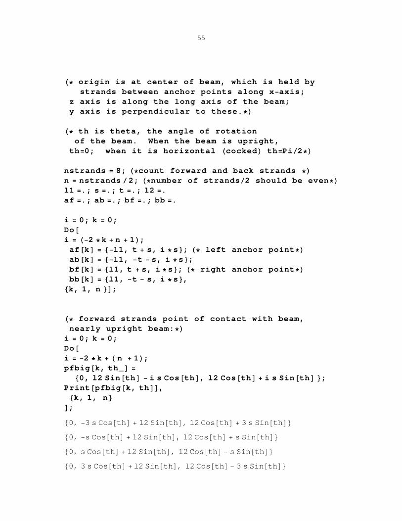
55
origin is at center of beam, which is held bystrands between anchor points along x axis;
z axis is along the long axis of the beam;y axis is perpendicular to these.
th is theta, the angle of rotationof the beam. When the beam is upright,
th 0; when it is horizontal cocked th Pi 2
nstrands 8; count forward and back strandsn nstrands 2; number of strands 2 should be evenl1 .; s .; t .; l2 .af .; ab .; bf .; bb .
i 0; k 0;Doi 2 k n 1 ;af k l1, t s, i s ; left anchor pointab k l1, t s, i s ;bf k l1, t s, i s ; right anchor pointbb k l1, t s, i s ,k, 1, n ;
forward strands point of contact with beam,nearly upright beam:
i 0; k 0;Doi 2 k n 1 ;pfbig k, th_
0, l2 Sin th i s Cos th , l2 Cos th i s Sin th ;Print pfbig k, th ,
k, 1, n;
0, 3 s Cos th l2 Sin th , l2 Cos th 3 s Sin th
0, s Cos th l2 Sin th , l2 Cos th s Sin th
0, s Cos th l2 Sin th , l2 Cos th s Sin th
0, 3 s Cos th l2 Sin th , l2 Cos th 3 s Sin th

56
back strands point of contact with beam,nearly upright beam
i 0; k 0;Doi 2 k n 1 ;pbbig k, th_
0, l2 Sin th i s Cos th , l2 Cos th i s Sin th ;Print pbbig k, th ,
k, 1, n;
0, 3 s Cos th l2 Sin th , l2 Cos th 3 s Sin th
0, s Cos th l2 Sin th , l2 Cos th s Sin th
0, s Cos th l2 Sin th , l2 Cos th s Sin th
0, 3 s Cos th l2 Sin th , l2 Cos th 3 s Sin thcheck these for vertical beam
Do Print pfbig k, Pi 2, k, 1, nDo Print pbbig k, Pi 2, k, 1, n
0, l2, 3 s
0, l2, s
0, l2, s
0, l2, 3 s
0, l2, 3 s
0, l2, s
0, l2, s
0, l2, 3 s
57
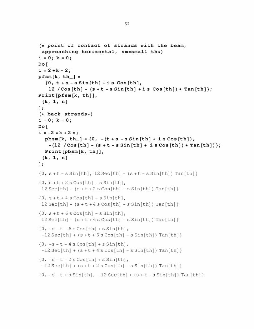
point of contact of strands with the beam,approaching horizontal, sm small th
i 0; k 0;Doi 2 k 2;pfsm k, th_
0, t s s Sin th i s Cos th ,l2 Cos th s t s Sin th i s Cos th Tan th ;
Print pfsm k, th ,k, 1, n
;back strands
i 0; k 0;Doi 2 k 2 n;
pbsm k, th_ 0, t s s Sin th i s Cos th ,l2 Cos th s t s Sin th i s Cos th Tan th ;
Print pbsm k, th ,k, 1, n
;
0, s t s Sin th , l2 Sec th s t s Sin th Tan th
0, s t 2 s Cos th s Sin th ,l2 Sec th s t 2 s Cos th s Sin th Tan th
0, s t 4 s Cos th s Sin th ,l2 Sec th s t 4 s Cos th s Sin th Tan th
0, s t 6 s Cos th s Sin th ,l2 Sec th s t 6 s Cos th s Sin th Tan th
0, s t 6 s Cos th s Sin th ,l2 Sec th s t 6 s Cos th s Sin th Tan th
0, s t 4 s Cos th s Sin th ,l2 Sec th s t 4 s Cos th s Sin th Tan th
0, s t 2 s Cos th s Sin th ,l2 Sec th s t 2 s Cos th s Sin th Tan th
0, s t s Sin th , l2 Sec th s t s Sin th Tan th

58
check for horizontal beamDo Print pfsm k, 0 , k, 1, nDo Print pbsm k, 0 , k, 1, n
0, s t, l2
0, 3 s t, l2
0, 5 s t, l2
0, 7 s t, l2
0, 7 s t, l2
0, 5 s t, l2
0, 3 s t, l2
0, s t, l2

59
input the parameters here,then calculate angle at which the attachment pointsinterfere with the movement of the strands
param l2 2, l1 10., s 1., t 1.param l2 11.4,s 3,t 7limit on movement of strand
solz .phz .
sol Solve Cos phzt s n 1 s Sqrt 1 Cos phz Cos phz l2 s ,
phz ;
k 4; search solutions for correct one
solz phz . sol k the limiting angle for phithe Pi 2 phz . sol k . param
the limiting angle for th
themeans th when top strand hits support, extremal
thdeg 180 Pi the
l2 2, l1 10., s 1., t 1.
Solve::ifun : Inverse functions are being used by Solve,so some solutions may not be found.
ArcCosl2 s s2 l2 t s t 3 s l22 2 l2 s 9 s2 2 s t t2
l22 2 l2 s 10 s2
1.27628
73.1255

60
check that the two solutionsare continuous at the theta extreme
DoPrint pfsm i, the . param ;Print pfbig i, the . param ; Print ,
i, 1, n
0, 1.04306, 3.45138
0, 1.04306, 3.45138
0, 1.62361, 1.5375
0, 1.62361, 1.5375
0, 2.20416, 0.37639
0, 2.20416, 0.37639
0, 2.78471, 2.29028
0, 2.78471, 2.29028

61
check back strands; pairs should be equalDoPrint pbsm i, the . param ;Print pbbig i, the . param ; Print ,
i, 1, n
0, 2.78471, 2.29028
0, 2.78471, 2.29028
0, 2.20416, 0.37639
0, 2.20416, 0.37639
0, 1.62361, 1.5375
0, 1.62361, 1.5375
0, 1.04306, 3.45138
0, 1.04306, 3.45138
Combine these for thegeneral case where beam is at angle thboole True means restricted movement
boole .pfn k_, th_, boole_ : If boole, pfsm k, th , pfbig k, th ;pbn k_, th_, boole_ : If boole, pbsm k, th , pbbig k, th ;

62
The unit vectorsin direction of tension; L left; R right
DoTfL k_, th_, b_ : Simplify pfn k, th, b af k
Sqrt pfn k, th, b af k . pfn k, th, b af k ;TfR k_, th_, b_ : Simplify pfn k, th, b bf k
Sqrt pfn k, th, b bf k . pfn k, th, b bf k ;TbL k_, th_, b_ : Simplify pbn k, th, b ab k
Sqrt pbn k, th, b ab k . pbn k, th, b ab k ;TbR k_, th_, b_ : Simplify pbn k, th, b bb k
Sqrt pbn k, th, b bb k . pbn k, th, b bb k ,k, 1, n
;

63
forces coming from each strandDoforcefn k_, x_, b_ : TfL k, x, b TfR k, x, b ;forcebn k_, x_, b_ : TbL k, x, b TbR k, x, b ,
k, 1, n;rfn k_, th_, b_ : pfn k, th, b ;rbn k_, th_, b_ : pbn k, th, b ;torque tension add in pairs;note the tension is a function of angle;
torqueovten k_, th_, b_ :CrossProduct rfn k, th, b , forcefn k, th, bCrossProduct rbn k, th, b , forcebn k, th, b ;
torqtotovten th_, b_ :Sum torqueovten k, th, b , k, 1, n ;
torqueovtenstot th_ : If th the,torqtotovten th, True , torqtotovten th, False 1 ;
torque tension add in pairs;note the tension is a function of angle;
torqueovten k_, th_, b_ :CrossProduct rfn k, th, b , forcefn k, th, bCrossProduct rbn k, th, b , forcebn k, th, b ;
torqtotovten th_, b_ :Sum torqueovten k, th, b , k, 1, n ;
torqueovtenstot th_ : If th the,torqtotovten th, True , torqtotovten th, False 1 ;

64
check these:j 4;torqueovten j, Pi 2, False should be zeroforcefn j, Pi 2, False should be only along y axisSimplify forcefn j, Pi 2, False forcebn 1, Pi 2, False
should be zero
0, 0, 0
0,2 l2 s t
l12 l2 s t 2, 0
0, 0, 0ListPlot Table th, torqueovtenstot th . param ,
th, 0, Pi 2, .1 , PlotLabel param,AxesLabel " ", "torque tension"
0.2 0.4 0.6 0.8 1 1.2 1.4
2
4
6
8
10
torque tension l2 2, l1 10., s 1., t 1.
Graphics

65
There are two possibilities: the tension maybe unequal in the different strands if theattachment points at the ends of the strandshave high friction. On the other hand,
if there is no friction, the tension is the same inall strands: the length changes experienced by the
strands is distributed over all of the strands.
length of the kth forward strand:lenstrand k_, th_, b_ :Sqrt pfn k, th, b af k . pfn k, th, b af k ;
lenstrandtot k_, th_ : If th the,lenstrand k, th, True , lenstrand k, th, False ;
luprt k_ : lenstrandtot k, Pi 2 ; starting length
frlenchng k_, th_ :lenstrandtot k, th luprt k 1. . param

66
assume high friction at attachment points A and Bto see how the length changes for each strand
ListPlotTable th, frlenchng 1, th . param , th, 0, Pi 2, .02 ,PlotLabel param, AxesLabel " ", "delta len len"
0.25 0.5 0.75 1 1.25 1.5
0.002
0.004
0.006
0.008
0.01
0.012
0.014
delta len len l2 2, l1 10., s 1., t 1.
Graphics

67
ListPlotTable th, frlenchng 2, th . param , th, 0, Pi 2, .02 ,PlotLabel param, AxesLabel " ", "delta len len"
0.25 0.5 0.75 1 1.25 1.5
0.005
0.01
0.015
0.02
0.025
delta len len l2 2, l1 10., s 1., t 1.
GraphicsListPlotTable th, frlenchng 3, th . param , th, 0, Pi 2, .02 ,PlotLabel param, AxesLabel " ", "delta len len"
0.25 0.5 0.75 1 1.25 1.5
0.02
0.04
0.06
0.08
0.1
0.12
delta len len l2 2, l1 10., s 1., t 1.
Graphics

68
ListPlotTable th, frlenchng 4, th . param , th, 0, Pi 2, .02 ,PlotLabel param, AxesLabel " ", "delta len len"
0.25 0.5 0.75 1 1.25 1.5
0.05
0.1
0.15
0.2
0.25
delta len len l2 2, l1 10., s 1., t 1.
Graphicsnow assume that the tensionin the strands are equal, independent of k
torq th_, b_ :Sum torqueovten k, th, b frlenchng k, th , k, 1, n ;
torquetot th_ :If th the, torq th, True , torq th, False 1 ;

69
ListPlotTable th, torquetot th . param , th, 0, Pi 2, .1 ,PlotLabel param, AxesLabel " ", "torque k"
0.2 0.4 0.6 0.8 1 1.2 1.4
0.2
0.4
0.6
0.8
1
1.2
torque k l2 2, l1 10., s 1., t 1.
Graphics
lensum th_ : Sum lenstrandtot k, th , k, 1, n ;lensum 0 length when beam is horizontal
l12 l2 3 s 2 l12 l2 s 2 4 s2 l12 16 s2 l2 s 2
l12 36 s2 l2 3 s 2
lensum Pi 2 length when beam is vertical
4 l12 l2 s t 2

70
length change for allthe strands as a function of th. Assumesall the strands are under equal tension
ListPlot Table th, lensum th lensum Pi 2 . param ,th, 0, Pi 2, .1 , PlotLabel param,
AxesLabel " ", "length"
0.2 0.4 0.6 0.8 1 1.2 1.4
1.02
1.04
1.06
1.08
1.1
length l2 2, l1 10., s 1., t 1.
Graphics