Fault-Tolerant Platform for Intra-Spacecraft Modular Wireless

On TTEthernet for Integrated Fault-Tolerant
Spacecraft Networks
Andrew Loveless∗
NASA Johnson Space Center, Houston, TX, 77058
There has recently been a push for adopting integrated modular avionics (IMA) princi-ples in designing spacecraft architectures. This consolidation of multiple vehicle functionsto shared computing platforms can significantly reduce spacecraft cost, weight, and de-sign complexity. Ethernet technology is attractive for inclusion in more integrated avionicsystems due to its high speed, flexibility, and the availability of inexpensive commercialoff-the-shelf (COTS) components. Furthermore, Ethernet can be augmented with a varietyof quality of service (QoS) enhancements that enable its use for transmitting critical data.TTEthernet introduces a decentralized clock synchronization paradigm enabling the use oftime-triggered Ethernet messaging appropriate for hard real-time applications. TTEther-net can also provide two forms of event-driven communication, therefore accommodatingthe full spectrum of traffic criticality levels required in IMA architectures. This paperexplores the application of TTEthernet technology to future IMA spacecraft architecturesas part of the Avionics and Software (A&S) project chartered by NASA’s Advanced Ex-ploration Systems (AES) program.
Nomenclature
A&S = Avionics and Software ProjectAA2 = Ascent Abort 2AES = Advanced Exploration Systems ProgramANTARES = Advanced NASA Technology Architecture for Exploration StudiesAPI = Application Program InterfaceARM = Asteroid Redirect MissionBAG = Band Allocation GapBE = Best-EffortC&DH = Command and Data HandlingCFS = Core Flight SoftwareCM = Compression MasterCOTS = Commercial Off-The-ShelfCT = Critical TrafficCTID = Critical Traffic IdentifierDMA = Direct Memory AccessEDGE = Engineering DOUG Graphics EnvironmentES = End SystemGNC = Guidance, Navigation, and ControlIMA = Integrated Modular AvionicsIPAS = Integrated Power, Avionics, and SoftwareIPS = Internet Protocol SuiteIPv4 = Internet Protocol version 4ISS = International Space StationJSC = Johnson Space Center
∗Software Engineer, Command and Data Handling Branch, 2101 NASA Parkway, Houston, TX
1 of 23
American Institute of Aeronautics and Astronautics
https://ntrs.nasa.gov/search.jsp?R=20150014489 2020-03-29T15:35:48+00:00Z
LAN = Local Area NetworkLAS = Launch Abort SystemMAC = Media Access ControlMPCV = Multi-Purpose Crew VehiclePCF = Protocol Control FramePIO = Programmed Input/OutputQoS = Quality of ServiceRC = Rate-ConstrainedRTOS = Real-Time Operating SystemSC = Synchronization ClientSLS = Space Launch SystemSM = Synchronization MasterTCP = Transmission Control ProtocolTDM = Time-Division MultiplexingTT = Time-TriggeredUDP = User Datagram ProtocolVL = Virtual LinkVOQ = Virtual Output Queue
I. Introduction
Aerospace projects have traditionally employed federated avionics architectures, in which each computersystem is designed to perform one specific function (e.g. navigation). There are obvious downsides tothis approach, including excessive weight (from so much computing hardware), and inefficient processorutilization (since modern processors are capable of performing multiple tasks). There has therefore been apush for integrated modular avionics (IMA), in which common computing platforms can be leveraged fordifferent functions.1 One major challenge with this approach is the need to prevent non-critical failures frompropagating through shared hardware resources and negatively impacting more critical systems. In fact,most avionic system failures result from ineffective fault containment and the resulting domino effect.2
As the glue connecting integrated systems, the data network plays a crucial role in error prevention andfailure recovery.2 Furthermore, the network must accommodate traffic of mixed criticality and performancelevels – potentially all related to the same shared computer hardware. The difficulty this poses causes mostmodern spacecraft to take a hybrid architecture approach that is neither fully federated nor integrated.Several different types of networks are incorporated, each suited to support a specific vehicle function.
Critical functions are typically driven by precise timing loops, requiring networks with strict guaranteesregarding message latency (i.e. determinism) and fault-tolerance.3 One technique such networks employ istime-division multiplexing (TDM), in which messages are sent among connected nodes one at a time and in aspecific order. This methodology reduces wiring by allowing network resources to be shared without conflicts.Early approaches to TDM in avionics, such as the MIL-STD-1553 data bus, used an asynchronous master-slave architecture. The need for central bus controllers to command remote devices (when to send/receive),however, resulted in low speeds and high overhead.4 Several more contemporary technologies instead follow adistributed time-triggered paradigm, in which clock synchronization between nodes enables precise schedule-driven communication. These architectures offer many advantages in safety-critical applications, loweringjitter while providing additional fault tolerance by removing single points of failure.5
Alternatively, non-critical systems generally employ data networks prioritizing flexibility and high per-formance over reliable operation. Examples of these technologies are often found interfacing communicationequipment and high speed instrumentation to onboard computer systems. The success of switched Ethernettechnology in filling this role in terrestrial applications makes it desirable for inclusion in future spacecraftplatforms. Basic Ethernet configurations have been incorporated into several preexisting aerospace projects,including both the Space Shuttle and International Space Station (ISS).6
But Ethernet’s use has not been limited to handling noncritical data. Over the past several decades,many proprietary Ethernet variants (with various quality of service (QoS) enhancements) have been createdfor time-critical industrial and manufacturing applications. This push for “Industrial Ethernet” largelystems from its scalability, high speed, and the availability of inexpensive commercial off-the-shelf (COTS)components. Similarly, ARINC 664-p7 standardizes an Ethernet variant with increased determinism and
2 of 23
American Institute of Aeronautics and Astronautics
reliability for aerospace applications.7 It accomplishes this through the concept of rate-constrained traffic,in which predetermined knowledge of traffic patterns can ensure a theoretical upper bound on transmissiondelays.
TTEtherneta further closes the gap towards the goal of achieving fully deterministic Ethernet commu-nication by introducing the principles of decentralized clock synchronization and time-triggered messaging.Besides time-triggered messages (TT), TTEthernet is also capable of supporting two forms of event-drivencommunication – rate-constrained (RC) and best-effort (BE). The RC traffic class is functionally equivalentto ARINC 664-p7. BE traffic behaves comparably to traditional layer 2 Ethernet, with no guarantees regard-ing timely (or even successful) message delivery.8 In this way, TTEthernet overcomes difficulties in realizingan IMA architecture, providing three distinct traffic classes covering the entire spectrum of criticality levels.Common computing platforms (e.g. line-replaceable units) can share networking resources in such a waythat failures in non-critical systems (using BE or RC communication modes) cannot impact flight-criticalfunctions (using TT communication). A variant of TTEthernet, named Time-Triggered Gigabit Ethernet(TT-GbE), is deployed as part of the onboard data network (ODN) on NASA’s Orion spacecraft.
This paper explores the application of the TTEthernet technology to future spacecraft as part of theAvionics and Software (A&S) project chartered by NASA’s Advanced Exploration Systems (AES) program.First, goals of the A&S project are stated, and IMA considerations in network development are presented.The shortcomings of classical Ethernet in time-critical applications are discussed, along with how the TTEth-ernet technology overcomes these deficiencies. Next, a general overview of TTEthernet is provided. The useof TTEthernet is then demonstrated, providing real-time failover capability between redundant flight com-puters running Core Flight Software (CFS) in two distinct simulated mission scenarios: 1) Asteroid RedirectMission (ARM) and 2) Orion Ascent Abort 2 (AA2) flight test. The AA2 mission in particular imposedsignificant constraints on the flight control loop – necessitating the development of a software-level networkstack to accommodate larger data payloads, as well as the implementation of network-based flight computersynchronization to handle failure in such a critical mission phase. Lastly, the application of TTEthernet tofuture projects is discussed.
II. The Avionics and Software Project
As private industry begins transporting astronauts to the International Space Station (ISS) throughthe Commercial Crew Program, NASA will shift its focus towards furthering human spaceflight explorationbeyond low earth orbit (LEO). Though future mission scenarios are unknown, possible targets include Earth-Moon Lagrange points, near earth asteroids (NEAs), and Mars.9 Though vehicle requirements differ foreach objective, spacecraft avionics must incorporate similar technologies to enable success in any deep spacemission. Because the field of avionics is advancing so rapidly in terrestrial applications, NASA can minimizedevelopment time and cost by utilizing existing commercial technologies.
It is the goal of the A&S project to discern the most promising of these options, mature them forfuture use, and lower the risk of their inclusion in other projects. Leveraging this work, the A&S project isdeveloping a flexible mission agnostic spacecraft architecture according to IMA principles that is adaptableto a wide variety of future mission scenarios. The A&S team includes participants across NASA centers,other government agencies, and industry partners. The Integrated Power, Avionics, and Software (IPAS)facility at Johnson Space Center (JSC) is used extensively to demonstrate integration, providing a flexibleevaluation environment for avionics components and software in a realistic framework of vehicle subsystems.6
III. IMA Considerations in Networking
Probable future missions (e.g. NEAs, Mars) may take months to years to complete. However, while longterm missions operating in LEO can be periodically resupplied from earth, it is too costly to continuouslysupport vehicles traveling to further destinations.9 This combination of long duration and inaccessibilityhighlights the importance of adopting integrated modular avionics principles when designing future spacecraftarchitectures.
Early manned spacecraft, such as those of the Apollo program, were designed with federated architectures,in which no distinction exists between software and hardware. Each computer system was built to perform
aTTEthernet is the further commercial development of the TT-Ethernet research jointly conducted between the ViennaUniversity of Technology and TTTech Computertechnik AG.8
3 of 23
American Institute of Aeronautics and Astronautics

one specific function. Because software under this paradigm is inherently contained by distinct hardwareplatforms, faults cannot propagate to other systems. Space partitioning also ensures that software need notcompete for processor resources.1,2 Finally, the point-to-point wiring used in such architectures is highlydeterministic.
Though the federated methodology looks good on paper, it has several drawbacks – especially within thecontext of vehicles designed for long duration deep space missions. As many functions exist on a spacecraft,the need for so many computing platforms results in excessive weight and power consumption. This effectis compounded by the duplication of critical components (needed for redundancy) and the large number ofunique spares required to rectify failures. Additionally, long heavy runs of cable are necessary to connect thevehicle’s many discrete systems. The contribution of cabling to total vehicle weight cannot be ignored. Infact, the American Institute of Aeronautics and Astronautics (AIAA) recommends that 5-8% of a vehicle’son-orbit dry mass budget be allocated for cables alone.10
All these drawbacks present major issues when considering future spacecraft with limited ground supportand likely severe volume and mass restrictions. Also, the sheer amount of processors, spares, and wiringneeded to realize a federated architecture significantly increases the cost of avionic systems, which in turncan comprise more than 50% the cost of aerospace projects.11 Moreover, because each system is custombuilt to serve one function, any change to the vehicle architecture (e.g. networking previously unconnecteddevices) necessitates expensive hardware modification.
The IMA approach to avionics design emphasizes the use of shared hardware that performs multipledistinct vehicle functions. This methodology has been made possible by radical advancements in computingtechnology over the last several decades. Modern processors are more than capable of handling multipleconcurrent tasks, and faults can still be contained through techniques such as space partitioning (e.g. ded-icated registers or I/O) and software fault isolation.2 IMA offers significant cost and weight savings overfederated techniques, as the amount of computing platforms, spares, and wiring can be drastically reduced.Additionally, IMA’s emphasis on interchangeable components significantly increases overall system main-tainability by enabling one kind of spare to correct multiple types of failures. Proper use of IMA principlescan also significantly simplify the development process. The use of standard interfaces allows the vehicle’sarchitecture to adapt as its requirements evolve.
The main objective of an integrated architecture is to consolidate spacecraft functions to shared hardwareresources, while keeping the reliability federated designs provide. Accomplishing this task requires a “jackof all trades” data network, capable of accommodating traffic from multiple highly diverse systems (e.g.critical vs non-critical) that may all be realized on one shared computer platform. Because individualnetwork technologies are rarely so competent, however, the adoption of true IMA principles to networkarchitectures often proves unreasonable. Applying the same network architecture to the entire spacecraft,and thus systems of all criticality levels, generally results in undue expense and limited performance.
To illustrate this point, first imagine the communication architecture needed to stream 1080p video froma vehicle’s external cameras to an onboard crew display. What traits must this network possess? Highthroughput is obviously necessary, along with the flexibility to expand the network with new cameras asneeded. Next consider the network required to relay real-time measurements from a spacecraft’s externalproximity sensors to the flight computers. Could the video network also be leveraged to transmit this sensordata? Likely not, as it was not designed to guarantee the constant latency required by such a system.
Another major concern with consolidated networks is the potential for cascading faults between twosystems utilizing the same physical network connections. For example, it may be possible for a video camerato malfunction (e.g. babbling idiot behavior) saturating the network and preventing the delivery of themuch more critical sensor readings. The difficulty of implementing a truly integrated network causes mostmodern spacecraft architectures to take a hybrid approach, including four or more network technologies inone vehicle. For example, NASA’s lunar reconnaissance orbiter (LRO), launched in 2009, employs a MIL-STD-1553 bus, a SpaceWire network, high speed RS-422 lines, and multiple low-voltage differential signaling(LVDS) interfaces.12
IV. Ethernet is Promising
Ethernet technology has advanced tremendously over the last few decades, becoming a promising networkcandidate in the shift to more integrated systems. Ethernet is a family of standardized networking tech-nologies for peer-to-peer communication between nodes within a local area network. Originally developed at
4 of 23
American Institute of Aeronautics and Astronautics
Xerox PARC in the early 1970s, Ethernet quickly overtook competitors to become the dominant local areanetwork (LAN) technology in the business and IT sectors. Early implementations utilized a bus topologyin which multiple devices connect to one shared cable medium. In this case, an access control method isneeded to regulate bus traffic and limit message collisions. One such method, Carrier Sense Multiple Accesswith Collision Detection (CSMA/CD), directs nodes to wait a random interval after a collision is detectedbefore messages can be resent.13 Though a passable solution for low traffic networks, this behavior resultsin unacceptable delays as network utilization rises (and collisions become unavoidable). Switched Ethernetintroduced full duplex operation, consequently eliminating the problem of collision by allowing each nodeto send and receive packets simultaneously. Ethernet has become ubiquitous in day-to-day life and nowpresents a viable option for integrated avionics architectures.
Ethernet’s pervasive nature makes ensuring interoperability among devices easy to accomplish. Almostall hardware required to transmit or receive information, from gyroscopes to power controllers, can commu-nicate using Ethernet either natively or through the use of inexpensive adapters. The widespread availabilityof affordable compatible COTS Ethernet products is one of its most prominent advantages. Because COTScomponents have already been matured to the point of successful operation, minimal additional developmentis necessary before adoption – reducing cost and removing the schedule risk associated with the develop-ment of custom electronics. The high degree of commonality between Ethernet hardware also promotesinterchangeability between network devices and connectors. Furthermore, Ethernet networks are easily ex-panded, permitting the addition of new devices without any expensive hardware modification or changesto the network structure itself. As the architecture evolves, applications can be adapted using well-definedapplication program interfaces (APIs) and programming practices. Similarly, code can be recycled fromprevious projects to meet new requirements.
All these traits are highly desirable in a network required to integrate multiple systems. Additionally,Ethernet’s high throughput expands the range of traffic for which it can be utilized, even accommodatinghigh speed data streaming beyond the capabilities of most competing network technologies. Perhaps mostimportantly, Ethernet can be augmented with a variety of QoS enhancements that enable its use for trans-mitting critical data in hard real-time applications. Ethernet technology and its variants therefore permitthe creation of an integrated network architecture covering the full spectrum of traffic criticality levels.
Through consideration of the above factors, the A&S project has concluded that Ethernet is fundamentalin the design of any future avionics architecture for manned spacecraft. The utilization of Ethernet technologyhas also been encouraged by the A&S project’s decision to maximize the use of Core Flight Software (CFS)whenever possible. Certified for human spaceflight at Johnson Space Center in 2014, CFS provides a set offlexible software services compatible with a variety of processor architectures and operating systems. In CFS,separate applications each perform distinct functions on the vehicle – including controlling power data units(PDUs) and monitoring cabin pressure. These applications all heavily employ the Internet Protocol Suite(IPS) for onboard communication, further supporting the need for Ethernet in future vehicle architectures.The A&S project’s focus on Ethernet communication, and utilization of Core Flight Software, has led tothe development of a well-defined IP-based backbone showcased in Johnson Space Center’s IPAS facility.This infrastructure, however, is only suitable for transmitting nonessential data with low quality of servicerequirements.6
V. The Shortcomings of Classical Ethernet
Though the introduction of switches stopped collisions, timing within an Ethernet network is still notpredictable. This shortcoming stems from the event-driven nature of its communication, in which messagesare only sent in response to environmental or internal events. To understand how this variable delay occurs,it is first necessary to explore the underlying fundamentals of switch operation.
The basic purpose of a network switch is to forward frames from a given input (ingress) port to aparticular output (egress) port. Modern switches accomplish this task through a crosspoint matrix switchingfabric.13 The event-triggered paradigm of Ethernet communication suggests that multiple messages will, atsome point, inevitably need to travel through this matrix simultaneously. This concurrent communication isusually supported by nature of the switch fabric’s parallel arrangement, in which data pathways are separatedthrough space partitioning. Collisions, however, eventually occur as multiple frames are simultaneouslyforwarded to the same output port.14
This phenomenon closely resembles the issue of message collision observed in early Ethernet systems
5 of 23
American Institute of Aeronautics and Astronautics

utilizing shared bus technology. As CSMA/CD was employed to regulate access to a shared data medium,crossbar switches must too utilize a process to regulate input to the switch fabric. This regulation isgoverned by an onboard processor commonly referred to as the switch allocator. For each clock cycle, theswitch allocator must determine which of the switch’s ingress and egress ports should be connected.15 Severalschemes exist to provide fair contention resolution at high rates.
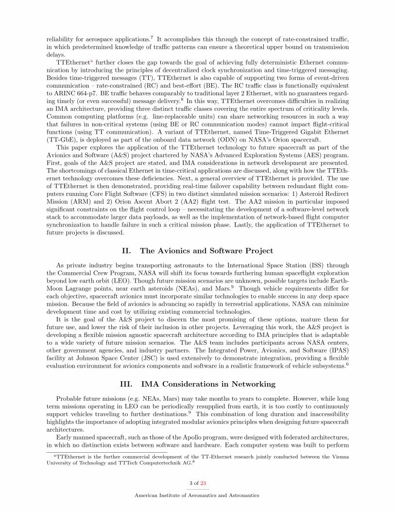
Simple approaches employ queuing buffers at the incoming switch ports. This memory space is managedby the switch allocator and used to temporarily store messages entering the switch. As messages are received,the input buffers send requests to the switch allocator for connections to the output ports based on thedestinations of the frames they contain (determined by routing logic). In an arrangement employing a singlefirst-in, first-out (FIFO) queue per switch input, each ingress queue may make one request per clock cycle.A simplified switch allocator is composed of one fabric arbiter per output channel. Each arbiter recognizeswhen multiple buffers are requesting access to its output port. To prevent collision, it uses an arbitrationscheme to decide which input port to service. Each arbiter performs this operation independently, and mayonly grant one request per clock cycle.14,15
Arbiter
MUX MUX MUX
Arbiter Arbiter
Switching Fabric
Requests
Input Queues
Figure 1. Input-buffered switch described in Ref. 15.
This collision arbitration process makes transmis-sion time in Ethernet networks inherently unpredictable.The delay a message experiences when passing througha switch depends heavily on contention from competinginputs and the arbitration method used. Since messagesmay reach the network switches at any time, the fre-quency and severity of conflicts is highly variable.
Contention within the switch can significantly limitits overall throughput. In fact, basic switches employ-ing input FIFO queues can realistically only exhibit amaximum throughput of 58.6% under uniform traffic ar-rivals.16 In extreme cases, the switch may not be ableto keep up with the rate at which it receives frames, theinternal buffers may overflow, and messages must be dis-carded. Higher level protocols (e.g. Transmission Con-trol Protocol (TCP)) can ensure successful delivery andmessage sequencing, but introduce significant overheadand unpredictable delay from repeated transmissions.
Efforts to increase throughput in network switches include the use of virtual output queues (VOQs),crosspoint buffers, and improved arbitration procedures (matrix, wavefront). The use of VOQs particularlyimproves throughput in modern high performance switches, lowering congestion by having each input portmaintain a separate queue for each possible output. Because each VOQ at a given input port corresponds toa separate output channel, frames intended for busy output ports do not prevent messages destined for freeports from being delivered. In this way, use of VOQs can eliminate the classical head-of-line blocking problemseen in basic FIFO input-buffered switches.15 Switches employing VOQs can achieve 100% throughputunder uniform traffic, but not under more realistic non-uniform traffic patterns. Two-stage switches havebeen proposed to overcome this barrier. The first stage acts as a load balancer, spreading traffic evenlyover the second stage – a typical VOQ input-buffered switch. Such designs have achieved 100% throughputin simulation, but introduce additional complexity as packets may be arbitrarily mis-sequenced betweenstages.17
Even with the addition of VOQs, the amount of delay experienced by any one frame is highly variable.This behavior results from two major limitations: 1) only one VOQ per input port may forward a messageper clock cycle, 2) output ports can only send one message per clock cycle. In the unpredictable case ofmultiple frames competing for access to the same egress port, transmission is delayed an unknown amountas messages are forwarded out one at a time.18
We see then that the uncoordinated nature of Ethernet communication, even with modern advancementsin switch technology, unavoidably leads to message contention within network switches. In all such instancesan arbitration process must be used to resolve conflicts, introducing variation in the time it takes for messagesto be forwarded. Though well suited for some purposes, network technologies requiring an arbitration processfor message transmission are commonly considered inadequate for use in hard real-time spacecraft applica-tions.5 Even priority-based arbitration schemes, in which higher priority messages are expressly favored, do
6 of 23
American Institute of Aeronautics and Astronautics
not provide tolerable certainty. Minor variations in message latency can alter which messages contend atany given arbitration cycle and quickly result in unanticipated system behavior.19 Flight critical functionsmust operate in an entirely predictable manner, and thus require a high level of network determinism thatclassical Ethernet cannot provide.
VI. The Role of TTEthernet in the A&S Project
The A&S project’s investigation of TTEthernet is an effort to extend the capabilities of the currentEthernet backbone to accommodate time-critical data, thus realizing a more closely integrated networkarchitecture. TTEthernet can support the full spectrum of traffic criticality levels by employing event-based and time-triggered traffic classes. These enable the simultaneous transmission of both high speedlow-priority and time-critical data within the same network and over the same physical layer.8 In thisway, TTEthernet solves one major problem faced when designing networks according to IMA principles– finding a network technology suitable for the full range of traffic varieties transmitted from a sharedcomputer system performing functions with multiple criticality levels. Furthermore, TTEthernet’s trafficclasses provide a hard fault containment method within the network itself, as delivery of time-triggeredmessages is guaranteed regardless of erroneous traffic patterns in lower priority classes.
Fault containment, however, is not limited to the interaction between traffic classes. The scheduled natureof time-triggered messaging ensures that critical systems may only access the network at times previouslyspecified in the communication schedule. Furthermore, switches may be configured as bus guardians tocontain the arbitrary failure of individual TTEthernet devices, preventing well known faults likes babblingidiot behavior from affecting other systems. Cascading faults between computing platforms can thus bereduced without the need for complex fault isolation procedures within the software applications themselves.
Additionally, TTEthernet employs the same frame payload size and structure as classical Ethernet. Anexisting application using conventional Ethernet communication can therefore be modified to instead employTTEthernet without requiring major software changes. This similar structure also enables the use of commonhigher level protocols, adding services like fragmentation/assembly, on top of TTEthernet’s data link layer.The A&S project is particularly attracted to the technology’s compatibility with its existing Ethernet networkarchitecture. TTEthernet hardware (e.g. switches, cabling) can be shared by both systems employingTTEthernet and classical Ethernet, saving weight, lowering power, and reducing integration complexity.
VII. TTEthernet Overview
This section explores key aspects of the TTEthernet protocol. Its goal is to provide a detailed overviewof the network structure, the role of each traffic class, and the synchronization process.
VII.A. Network Structure
TTEthernet networks are composed of specialized end systems and network switches connected throughbidirectional copper or fiber Ethernet links. An end system is typically realized as a TTEthernet networkadapter that occupies a standard expansion bus (e.g. CompactPCI, PCIe) in a computing platform. Al-ternatively, an end system can be implemented on a field-programmable gate array (FPGA) or even as astandalone software stack. Radiation hardened switches and end systems are also in development for futurespacecraft missions beyond LEO.
Message transmission between end systems is conducted according to a time-triggered paradigm. Anetwork planning tool is used to allocate each device a finite amount of time in which it may transmita frame. Each time slot is repeated sequentially to form a periodic communication schedule that is thenloaded onto each TTEthernet device (e.g. switches and end systems). Once the devices are configured, adecentralized synchronization process establishes a global time base among all network participants. Thecommunication schedule on each component references this synchronized time in order to dispatch messagesat predetermined instances. This schedule guarantees that no contention exists between time-triggeredEthernet frames in the network switches, therefore eliminating the need for arbitration (and the timingvariation it causes). End-to-end latency can thus be kept extremely low, and most importantly, nearlyconstant (jitter <1µs).20 Also, delivery of time-triggered messages is guaranteed.
Virtual links (VLs) are used to direct time-triggered messages between end systems. Each VL is defined
7 of 23
American Institute of Aeronautics and Astronautics

during the scheduling process and designates a logical connection between one sender and one or morerecipients. The virtual link associated with each time-triggered frame is denoted by a critical traffic identifier(CTID) occupying two bytes within the Ethernet header. The CTID is used to replace traditional mediaaccess control (MAC) based delivery seen in classical Ethernet systems. Each TTEthernet switch uses astatically defined forwarding table to associate individual VLs with corresponding output ports. All messagessent along the same virtual link are guaranteed to take the same path through the network as long as thenetwork configuration remains unchanged.21 This predictable behavior helps ensure constant transmissiontime between nodes. Furthermore, increased fault-tolerance can be achieved by using one virtual link tosend duplicated messages through multiple redundant switches.
TTEthernet Switch
ES3
ES1 ES2
ES4
VL6
VL8
Figure 2. A sample TTEthernet network.
Figure 2 demonstrates a sample TTEthernet network consistingof one switch and four end systems (ES1, ES2, ES3, ES4). Solidlines are used to represent physical connections, and dashed lines areused to represent data flow within the network. ES1 sends identicalframes to both ES3 and ES4 through VL6. ES4 transmits data toES2 through VL8.
Figure 3 shows the structure of a time-triggered Ethernet framecompared to that of a standard IEEE 802.3 Ethernet frame. Inboth cases, a 7 byte preamble allows the receiver to synchronizewith the timing of the received data, while a 1 byte start framedelimiter (SFD) is used to indicate the start of a new frame. In astandard Ethernet frame, the next two 6 byte fields contain MACaddresses for both the destination and the source. The following 2byte field is used to indicate either the length of the data payload orthe EtherType of the encapsulated protocol. This field, along withthe MAC address fields, composes the Ethernet header. The actualdata payload follows, occupying between 46 and 1500 bytes. Next, a 4 byte frame check sequence (FCS) isused for error detection. Lastly, an interpacket gap (IPG) equivalent to at least 12 bytes is required beforetransmission of a new frame.22,23
Preamble SFD DestinationAddress
EtherType(Length) Data Payload FCS IPG
7 bytes 1 byte 6 bytes 2 bytes 46-1500 bytes
SourceAddress
6 bytes 4 bytes 12 bytes
Preamble SFD CT Marker Data Payload FCS IPG
7 bytes 1 byte 4 bytes 2 bytes 46-1500 bytes6 bytes 4 bytes 12 bytes
Length
2 bytes
CTID SourceAddress
Figure 3. Structure of 802.3 Ethernet (top) and Time-Triggered Ethernet (bottom) frames (layer 2 only).
The only changes necessary to transform a standard Ethernet frame into a time-triggered frame (with noencapsulated protocol) are within the Ethernet header. In place of the MAC destination field is a 4 byte CTMarker and a 2 byte CTID. The CT Marker is a static identifier used to distinguish time-triggered framesfrom other Ethernet traffic. The CTID is used by the switches to route time-triggered frames through thenetwork. Finally, the last 2 bytes of the header are expressly used to contain the payload length.
VII.B. Traffic Class Integration
Besides time-triggered messaging, TTEthernet networks may provide two additional traffic classes to supportcommunication of different criticality levels. TTEthernet coordinates transmission of all three traffic classesover the same physical connections. In this way, all traffic classes may coexist within one network.
Time-triggered (TT) messages are particularly suited for communication in hard real-time control sys-tems. Still, considerable effort is required to design the communication schedule upfront, and changes to thenetwork configuration necessitate changes to the schedule. The rate-constrained (RC) traffic class insteaduses an event-driven paradigm, providing increased flexibility for applications with less stringent latency anddeterminism requirements. Rate-constrained messaging is analogous to the communication method specifiedby the ARINC 664-p7 standard and seen in a wide range of aerospace applications. It uses the same virtuallink concept for message delivery as the time-triggered class, as well as the same Ethernet frame structure.
8 of 23
American Institute of Aeronautics and Astronautics
The frame payload size and rate of transmission are limited to predetermined maximums for each virtual link,and message delivery is guaranteed.8,22 The configuration of switch buffers can be adjusted to accommodatethe known worst-case traffic pattern and thus buffer overflows can be eliminated.20 Still the event-triggerednature of rate-constrained traffic requires that switches arbitrate between conflicting frames. As a result,transmission latency is more variable than that of the time-triggered class. The best-effort (BE) traffic classis also event-driven, and behaves akin to the messaging approach taken by classical Ethernet. No guaranteesare provided regarding transmission latency or successful message delivery.22 Best-effort messaging is thusonly appropriate for communication of nonessential data.
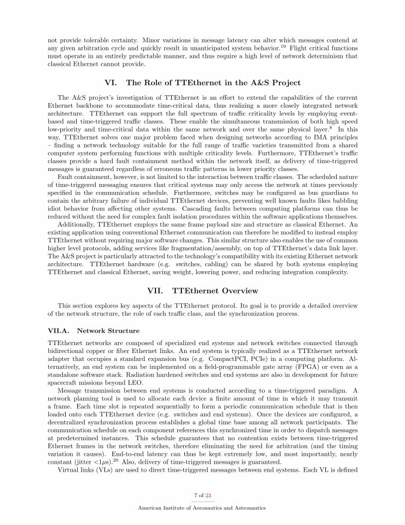
All three traffic classes can be integrated together within the same network. Time-triggered communica-tion is the highest priority. Its transmission cannot be hindered by the presence of any event-driven traffic(RC or BE). In the case that an end system chooses not to send a time-triggered message during its allocatedslot, the switch reclaims the bandwidth for use by event-based traffic.22 Event-driven traffic may use anybandwidth not taken by time-triggered messages. Out of the event-driven classes, rate-constrained trafficis always prioritized over best-effort traffic. Any best-effort messages are therefore restricted to the leftoverbandwidth not used by the higher priority classes.
Figure 4 shows the integration of multiple traffic classes within a TTEthernet network. Notice thatTT messages are forwarded as scheduled without delay, while event-driven traffic is transmitted as priorityallows.
TTEthernet Switch
ES2ES1
ES3
A B
C
B
A2ms 2ms 2ms
3ms 3ms
3ms 3ms
RC2
BE1BE1BE1
BE1BE1 BE1
RC2
RC2RC2
TT1 TT1 TT1
TT2 TT2
TT2TT2 TT1 TT1
2ms 2ms 2ms
6ms cluster cycle
C TT1
Figure 4. Integrated dataflow in a sample TTEthernet network.
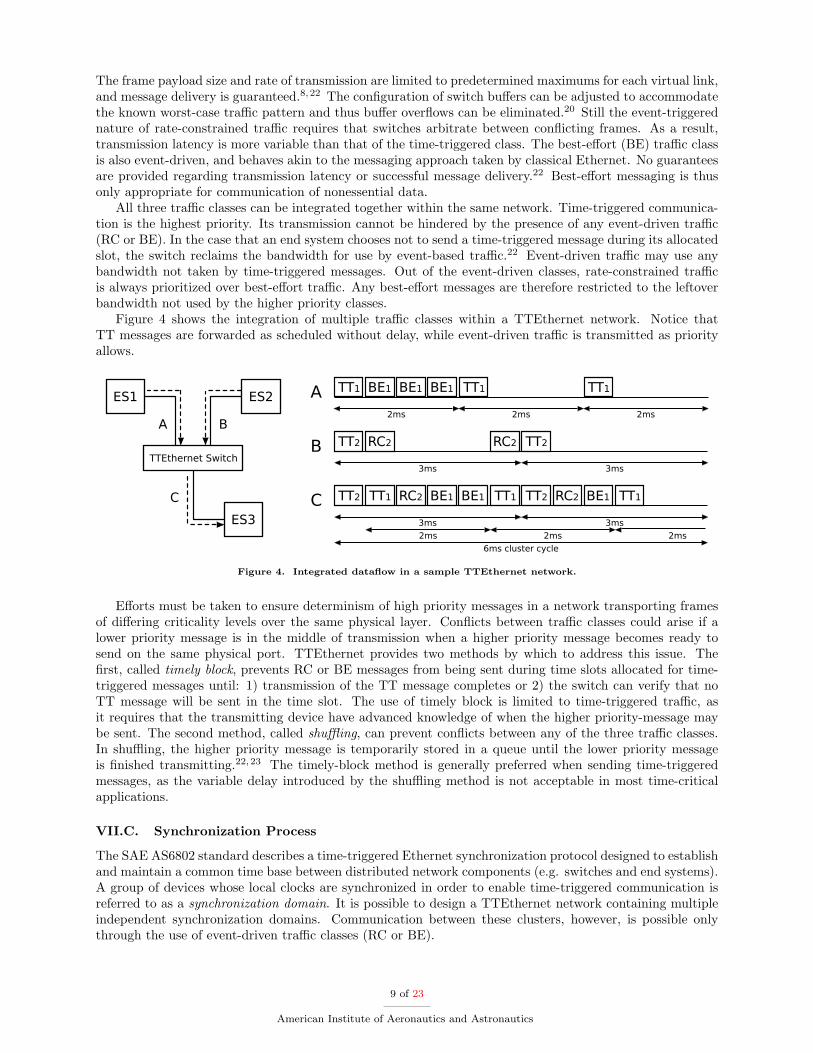
Efforts must be taken to ensure determinism of high priority messages in a network transporting framesof differing criticality levels over the same physical layer. Conflicts between traffic classes could arise if alower priority message is in the middle of transmission when a higher priority message becomes ready tosend on the same physical port. TTEthernet provides two methods by which to address this issue. Thefirst, called timely block, prevents RC or BE messages from being sent during time slots allocated for time-triggered messages until: 1) transmission of the TT message completes or 2) the switch can verify that noTT message will be sent in the time slot. The use of timely block is limited to time-triggered traffic, asit requires that the transmitting device have advanced knowledge of when the higher priority-message maybe sent. The second method, called shuffling, can prevent conflicts between any of the three traffic classes.In shuffling, the higher priority message is temporarily stored in a queue until the lower priority messageis finished transmitting.22,23 The timely-block method is generally preferred when sending time-triggeredmessages, as the variable delay introduced by the shuffling method is not acceptable in most time-criticalapplications.
VII.C. Synchronization Process
The SAE AS6802 standard describes a time-triggered Ethernet synchronization protocol designed to establishand maintain a common time base between distributed network components (e.g. switches and end systems).A group of devices whose local clocks are synchronized in order to enable time-triggered communication isreferred to as a synchronization domain. It is possible to design a TTEthernet network containing multipleindependent synchronization domains. Communication between these clusters, however, is possible onlythrough the use of event-driven traffic classes (RC or BE).
9 of 23
American Institute of Aeronautics and Astronautics

Each component (e.g. switch, end system) within a synchronization domain is assigned one of three rolescorresponding to its purpose during synchronization: Compression Master (CM), Synchronization Master(SM), or Synchronization Client (SC). The information necessary to establish and maintain synchroniza-tion between TTEthernet devices within a domain is transmitted in protocol control frames (PCF). Eachsynchronization role utilizes these PCFs in different ways as part of the overall synchronization process.Switches are typically configured as CMs, while end systems generally act as SMs.24
Synchronization is first established within the network by means of a fault-tolerant handshake betweenthe SMs and CMs. The SCs act simply to relay PCFs to their intended destination. The SMs dispatchspecialized coldstart frames to the CMs. The CMs then relay the messages back to the SMs, prompting thetransmission of a coldstart acknowledgement frame indicating the start of synchronized operation. Once aglobal time base has been established, it must be adjusted at regular intervals, called integration cycles, toaccount for clock drift within the network devices.23,24
SM
SMSM
CMSC1
2 3
21
5 5
5 5
Figure 5. Flow of protocol control frames in simpleTTEthernet network.
This process begins with all SMs dispatching PCFs tothe CMs at the same local time. As the local times on eachSM will have slightly diverged since the last resynchroniza-tion, the PCFs will actually be sent and subsequently re-ceived by the CMs at different points in time. The CMsthen use this variation in PCF reception time to calculatea new average global time.22,24 This global time is relayedback to both the SMs and SCs in another PCF, resynchro-nizing each devices local clock. Furthermore, TTEthernetprovides means to detect and correct the loss of synchro-nization between devices (e.g. clique detection).22
Figure 5 shows the transmission of PCFs within an ex-ample TTEthernet synchronization domain. All three endsystems are configured as synchronization masters. Oneswitch acts as a synchronization client, while another actsas a compression master.
The TTEthernet protocol is designed to tolerate a variety of end system and switch failures (e.g. arbitraryor inconsistent omission) without a degradation of essential services such as synchronization. In the mostextreme case, TTEthernet networks can be configured to tolerate the failure of any two network devices(dual-fault tolerant).24
VIII. TTEthernet Flight Computer Failover
This section explores the application of TTEthernet technology in two separate demonstrations of real-time failover between redundant flight computers running CFS in a simulated spaceflight mission. The firstwas an Asteroid Redirect Mission (ARM), in which flight computers controlled the Orion spacecraft (withESA’s ATV-derived service module) as it traveled over one thousand meters to dock with a robotic asteroidretrieval vehicle. Within this scenario, the flight computers were required to communicate using traditionalEthernet with two spacecraft systems external to the flight control loop – a crew display and EnvironmentalControl and Life Support System (ECLSS) simulator. The second mission, an Orion Ascent Abort 2 (AA2)flight test, simulated activation of the Launch Abort System (LAS) at the point where the Space LaunchSystem (SLS) undergoes the highest degree of aerodynamic stress (max Q). The LAS carried the Orioncrew module several thousand feet away from the rocket before reorienting the vehicle and detaching fromthe capsule. Unlike the ARM mission scenario, the AA2 test focused entirely on communication betweenthe flight computers and simulation. Several significant improvements to the TTEthernet-based networkarchitecture used in the ARM mission were made to meet the more pressing timing and data requirementsof the AA2 scenario. Software-based Internet Protocol version 4 (IPv4) and User Datagram Protocol (UDP)layers were developed to accommodate the larger message payload sizes. Furthermore, flight computersynchronization was implemented to ensure that all redundant machines processed data concurrently, andto enable failover between computers while guaranteeing no skipped or duplicated commands.
Next, prior efforts to demonstrate flight computer failover are presented and motivation for the imple-mentation of a TTEthernet-based failover architecture are discussed. The following subsections then describeeach key aspect of the ARM and AA2 demonstrations: 1) the structure of the flight software and flight con-
10 of 23
American Institute of Aeronautics and Astronautics
trol loop, 2) the integration of TTEthernet messaging into CFS, 3) the application of different failover andsynchronization methods, 4) the integration of TTEthernet with traditional IP-based Ethernet networks,and 5) the development of supporting software applications. Lastly, the setup of each failover demonstrationis described as shown in the A&S project’s September FY14 (ARM) and May FY15 (AA2) Integrated Testsat NASA JSC’s IPAS facility.
VIII.A. Background and Motivation
Implementing a fault-tolerant avionic system often necessitates the use of multiple distributed computingplatforms capable of performing identical tasks. The system is designed such that vehicle health is maintaineddespite the loss of one or more of these individual computers. This redundancy is especially important withinarchitectures designed by IMA principles, as each computer system may control multiple critical vehiclefunctions. Failover is one fundamental method of failure recovery in such distributed aerospace systems.Systems designed to carry out failover scenarios use the concept of primary and backup agents. When theprimary agent experiences a critical fault, its responsibilities are taken over by the backup through a failoverprocedure.25 The ideal result of this failover process is the return of standard vehicle functionality withoutdegraded performance. Failover among identical platforms is particularly suited to mitigate the effects ofboth random and end-of-life hardware failures.26 The Space Shuttle was the first major aerospace project toimplement automated failure detection and recovery. It employed a redundant set of four flight computers,each coordinating with specific sensors and effectors over a subset of vehicle data buses (depending on theprogram loaded). A separate backup flight computer was capable of communicating on all data buses incase of failures during critical mission phases (e.g. docking, reentry).27
Though failover methods are designed to allow backup flight computers to assume control of vehiclesystems, physical sensors and actuators are not always available in simulated mission environments. TheTrick Simulation Environment, locally developed at JSC, is used to model these absent systems (e.g. inertialmeasurement units) within the IPAS testbed. Trick is also used to model the vehicle’s trajectory throughspace and the dynamics of any other bodies of interest (e.g. service module, asteroids). The flight computerhardware can therefore interface directly with Trick in order to conduct simulated missions. Trick simulationsoftware has been used to support many NASA programs over the last several decades, including the SpaceShuttle, ISS, and Orion.28 Furthermore, the AA2 flight test simulation achieves high fidelity through utiliza-tion of the Advanced NASA Technology Architecture for Exploration Studies (ANTARES) simulation, theofficial NASA Orion spacecraft assessment tool used by JSC’s Guidance, Navigation, and Control (GNC)branch. ANTARES consists of several separately compiled models, packages, and libraries executed by theTrick simulation environment.29
Past efforts by the A&S project to demonstrate failover between flight computers utilized the existingIP-based Ethernet backbone. Because other vehicle systems were designed only to communicate with oneflight computer IP address at a time, a load balancer was needed to act as a virtual flight computer IP anddirect messages to/from both machines. This solution was demonstrated across multiple operating systems(e.g. Linux 2.6, VxWorks 6.9) and hardware platforms (e.g. non-flight-like, Maxwell SCS-750).6 Still, itsuffered the typical problems associated with using classical Ethernet for time-critical communication andprovided minimal fault-tolerance by introducing a single point of failure. While IP/Ethernet systems canachieve greater fault-tolerance through a variety of means (e.g. redundant load balancers, Virtual RouterRedundancy Protocol (VRRP)), these methods ultimately rely on devices to monitor each other throughthe network, and take over as necessary. Because this monitoring is dependent on the rules of traditionalbest-effort Ethernet, there are no guarantees regarding successful message delivery or travel time. Suchsystems are therefore inappropriate for use in critical applications.
TTEthernet was selected for subsequent iterations of the failover architecture as part of the A&S project’songoing efforts to introduce deterministic Ethernet technology to future spacecraft designs. Besides the gen-eral benefits of time-triggered Ethernet described earlier, some aspects of the technology make it particularlywell-suited for this application. First, TTEthernet’s use of virtual link based message forwarding removesthe need for a separate load balancer, as simple adjustments to the communication schedule ensure identicalmessages can be dispatched to several recipients simultaneously. These time-triggered channels also allowfailover to occur more seamlessly. Both the primary and backup computers are guaranteed to receive identi-cal data from the simulation at specific time intervals. This means that at the point in time that the primarycomputer is lost, the backup flight computer can begin reacting to the next set of fresh simulation data withno interruption. Additionally, the static nature of VL message paths ensures that the communication loop
11 of 23
American Institute of Aeronautics and Astronautics

between the flight computers and the simulation remain closed, while keeping the flight computers accessibleto other systems on the Ethernet backbone. Redundant TTEthernet switches can also be used to increasefault-tolerance. These switches can be hot-swapped with no negative impact on the running simulation.Finally, the periodic nature of time-triggered communication integrates well with CFS’s own schedule drivenarchitecture.
VIII.B. CFS Structure and Control Loop Setup
The implementation of TTEthernet-based failover requires integration of the TTEthernet library with theflight software running on each flight computer. The flight software is a derivative of the CFS productline maintained by Johnson Space Center’s Spacecraft Software Engineering Branch and used extensivelyin the IPAS environment. The integration of TTEthernet with CFS is important not just for this failoverapplication, but also so it may be leveraged in future spaceflight projects.
CFS provides a mission independent environment offering core services designed to insulate developersfrom underlying hardware and software dependencies. The long-term goal of CFS’s integrated core flightexecutive (cFE) is to facilitate the growth of a reusable bank of flight software applications.30 Because therequirements for command and data handling (C&DH) flight software are similar from project to project,the cost and turnaround time of future software development can be lowered through code reuse.31 JohnsonSpace Center is particularly interested in extending CFS’s capabilities for use in manned spaceflight appli-cations. The integration of TTEthernet facilitates the development of additional CFS applications that maycommunicate in safety-critical or mixed-criticality networks generally required by such projects.
The CFS product lines follows a layered architecture described in Ref. 32. Each layer masks the specificsof its underlying operation and can be changed without impacting the other layers.31 Among the bottomlayers is a hardware abstraction layer (HAL), offering a common library designed to provide plug and playcapability for qualified processors and other devices. The board support package (BSP) layer boots thisHAL, as well as the CFS and chosen operating system. Above this, the operating system abstraction layer(OSAL) provides a library interface enabling CFS compatibility with different operating systems. One layerhigher is the cFE itself, implementing six fundamental services required by flight software applications:Executive Service (ES), Software Bus Service (SB), Event Service (EVS), Table Service (TBL), File Service(FS), and Time Service (TIME). Lastly, the top layer houses all flight software applications. These includeboth pre-validated mission-independent modules and other applications tailored to a specific project.32
The CFS product line houses all essential flight software, including the cFE and all lower layers. Project-specific applications are instead located in the CFS workspace pertaining to an individual mission. Theseapplications communicate through the software bus (abstracted from sockets) implemented by the underlyingcFE. This bus follows a loosely-coupled publish-subscribe model, providing a structured architecture inwhich each application requires no knowledge of the underlying communication method (e.g. protocol,destination).33 The applications are scheduled to run periodically according to a global scheduling table.The CFS scheduler sends “wake up” messages to each application at preconfigured time intervals. Uponreceiving this message, an application executes exactly once. Typical schedules run at frequencies rangingfrom 100Hz to 500Hz. An adjustable script file controls which applications are loaded at start up andsubsequently run within the flight software.
Additional components are needed to actually conduct a simulated mission. The simulated vehicle’sGNC flight software is generated using a process similar to that used for the actual Orion spacecraft. TheMathWorks MATLAB and Simulink tools are used to auto-generate C++ source code from GNC algo-rithms. This code is compiled into a library and accessed from a CFS module housed in the CFS workspacecorresponding to the given project. The Multi-Purpose Crew Vehicle (MPCV) GNC workspace used inthe TTEthernet ARM failover test incorporated the genuine Orion Absolute Navigation (AbsNav) code forExploration Mission 1 (EM-1).28 The code used for the TTEthernet AA2 failover demonstration addedseveral improvements, including service module abort functionality, stochastic and optical navigation, andpropellant balancing in the crew module’s thruster logic.
Moreover, there are three ways by which the flight computers may communicate over the data network: 1)using the software bus (in the case of distributed flight computers), 2) via standard telemetry input/outputstreams, or 3) using purpose built interface applications (housed in the workspace) to send and receivemessages directly. By default, a flight computer and Trick simulation communicate using the third of theseoptions. This control loop employs dedicated “sim-to-fsw” and “fsw-to-sim” CFS applications to relay IPmessages with UDP or TCP transport layers depending on the requirements of the mission.
12 of 23
American Institute of Aeronautics and Astronautics
VIII.C. CFS TTEthernet Integration
In order to replace the closed loop’s IP-based communication method with time-triggered messaging, TTEth-ernet end systems realized on Altera FPGAs were installed in the simulation machine and each redundantflight computer. Furthermore, a shared CFS library was developed to provide compatibility between CFSand the new TTEthernet network adapters. This “hardware servicing” library interfaced applications withthe TTEthernet vendor library, which in turn interacted directly with the TTEthernet driver. The driverwas implemented as a loadable kernel module. The library was built along with the various flight softwareapplications and loaded according to the same CFS startup script. It allowed any CFS application within theworkspace to access core TTEthernet capabilities, including the ability to send and receive mixed-criticalitymessages. This library also performed setup or cleanup procedures automatically when CFS was initiatedor shutdown.
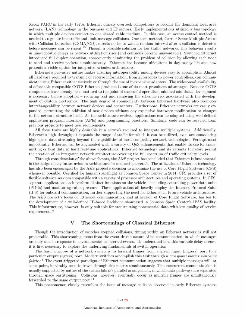
An extended vendor library was created to meet the needs of the AA2 flight test, including: 1) messagepayloads sizes up to 20,000 bytes and 2) throughput rates up to 100Mbit/s per Ethernet link. To satisfy thefirst requirement, the extended library included 80+ additional functions implementing a complete software-level network stack featuring IPv4 and UDP protocol layers. The extended library’s API replaced the defaultvendor-provided TTEthernet API, allowing applications to send or receive messages encapsulated as UDPdatagrams and IPv4 packets as TT, RC, or BE traffic.b When all protocol layers are utilized, messagepayloads up to 65,507 bytes can be transmitted over the network. This value is determined by: (65,535theoretical UDP length limit) − (8 byte UDP header) − (20 byte IPv4 header) = 65,507. The IPv4 andUDP layers were built according to Internet Engineering Task Force (IETF) publications RFC 791 and RFC768 respectively.34,35
The second requirement was addressed by the direct memory access (DMA) capabilities of the TTEth-ernet end systems. Communication through the TTEthernet library is possible using either programmedinput/output (PIO) or direct memory access (DMA). All incoming and outgoing transfers using the PIOmechanism must travel through the processor, limiting throughput to roughly 10Mbit/s - 30Mbit/s. DMA,however, enables full gigabit transmission speed by allowing the TTEthernet controller to access systemmemory independently of the host processor. The extended version of the TTEthernet library provides ahigher level of abstraction around use of TTEthernet’s DMA transfer mechanism, helping developers avoidcommon pitfalls when using the DMA interface to send/receive messages.
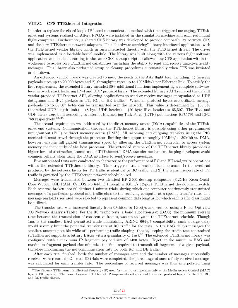
Five automated tests were conducted to characterize the performance of RC and BE read/write operationswithin the extended TTEthernet library. Time-triggered traffic was omitted because: 1) the overheadproduced by the network layers for TT traffic is identical to RC traffic, and 2) the transmission rate of TTtraffic is governed by the TTEthernet network schedule used.
Messages were transmitted between two identical HP Z400 desktop computers (3.2GHz Xeon Quad-Core W3565, 4GB RAM, CentOS 6.5 64-bit) through a 1Gbit/s 12-port TTEthernet development switch.Each test was broken into 60 distinct 1 minute trials, during which one computer continuously transmittedmessages of a particular protocol and traffic class to the receiving computer at a specific transfer rate. Themessage payload sizes used were selected to represent common data lengths for which each traffic class mightbe utilized.
The transfer rate was increased linearly from 0Mbit/s to 1Gbit/s and verified using a Fluke OptiviewXG Network Analysis Tablet. For the RC traffic tests, a band allocation gap (BAG), the minimum averagetime between the transmission of consecutive frames, was set to 1µs in the TTEthernet schedule. Though1ms is the smallest BAG permitted while maintaining ARINC 664-p7 compatibility, such a large delaywould severely limit the potential transfer rate of RC traffic for the tests. A 1µs BAG delays messages thesmallest amount possible while still performing traffic shaping, that is, keeping the traffic rate-constrained(TTEthernet supports arbitrary BAGs with a granularity of 1µs).36 The extended TTEthernet library wasconfigured with a maximum IP fragment payload size of 1480 bytes. Together the minimum BAG andmaximum fragment payload size minimize the time required to transmit all fragments of a given payload,therefore maximizing the net communication rate for both RC and BE traffic.
After each trial finished, both the number of messages sent and the number of messages successfullyreceived were recorded. Once all 60 trials were completed, the percentage of successfully received messageswas calculated for each transfer rate. The percentage of received messages was then interpolated using
bThe Phoenix TTEthernet Intellectual Property (IP) used for this project operates only at the Media Access Control (MAC)layer (OSI Layer 2). The newer Pegasus TTEthernet IP implements network and transport protocol layers for the TT, RC,and BE traffic classes.
13 of 23
American Institute of Aeronautics and Astronautics

Piecewise Cubic Hermite Interpolating Polynomial (PCHIP) interpolation to produce a continuous plot.PCHIP interpolation was chosen to avoid overshoots/undershoots in the resulting graph. Figure 6 displaysthe graphs produced as a result of all five throughput tests.
0 10 20 30 40 50 60Time (minutes)
0
200
400
600
800
1000
1200
Tran
smis
sion
Rat
e (M
bit/s
)
TX Rate% Received
0
20
40
60
80
100
Perc
ent R
ecei
ved
(%)
RC Raw Ethernet Frame (payload = 1500 bytes)
(a)
0 10 20 30 40 50 60Time (minutes)
0
200
400
600
800
1000
1200
Tran
smis
sion
Rat
e (M
bit/s
)
TX Rate% Received
0
20
40
60
80
100
Perc
ent R
ecei
ved
(%)
RC UDP Datagram w/ no frag (payload = 1472 bytes)
(b)
0 10 20 30 40 50 60Time (minutes)
0
200
400
600
800
1000
1200
Tran
smis
sion
Rat
e (M
bit/s
)
TX Rate% Received
0
20
40
60
80
100
Perc
ent R
ecei
ved
(%)
RC UDP Datagram w/ frag (payload = 8192 bytes)
(c)
0 10 20 30 40 50 60Time (minutes)
0
200
400
600
800
1000
1200
Tran
smis
sion
Rat
e (M
bit/s
)
TX Rate% Received
0
20
40
60
80
100
Perc
ent R
ecei
ved
(%)
BE UDP Datagram w/ no frag (payload = 1472 bytes)
(d)
0 10 20 30 40 50 60Time (minutes)
0
200
400
600
800
1000
1200
Tran
smis
sion
Rat
e (M
bit/s
)
TX Rate% Received
0
20
40
60
80
100
Perc
ent R
ecei
ved
(%)
BE UDP Datagram w/ frag (payload = 8192 bytes)
(e)
0 10 20 30 40 50 60Time (minutes)
0
200
400
600
800
1000
1200
Tran
smis
sion
Rat
e (M
bit/s
)
TX Rate% Received (Raw)% Received (UDP)
0
20
40
60
80
100
Perc
ent R
ecei
ved
(%)
RC Raw Ethernet and RC UDP Datagram(both 1514 byte frames)
(f)
Figure 6. Throughput analysis for RC and BE traffic in the TTEthernet library extension.
These plots can be used to determine the maximum effective throughput for each test – the highestpossible transmission rate at which no messages are dropped by the receiver. This value identifies a realisticupper throughput limit permitted by the extended TTEthernet library for a particular protocol, trafficclass, and payload size combination on the specific HP Z400 platform used for these tests. Because the IPv4and UDP layers were implemented in software, however, performance can vary significantly depending onthe hardware and operating system on which the extended TTEthernet library is utilized. Still, the highperformance seen in the above results demonstrates the merit of implementing an application-level networkstack on top of TTEthernet’s data-link layer.
For both the simulated ARM mission and AA2 flight test, the “sim-to-fsw” and “fsw-to-sim” CFS appli-cations were rewritten to send and receive time-triggered messages using functions in either the stock (forARM) or extended (for AA2) TTEthernet library. The Trick simulation was also modified to communicateusing time-triggered messages. In the simulated ARM mission, the “fsw-to-sim” application transmittedvehicle control commands to the Trick simulation at a frequency of 5Hz, while the “sim-to-fsw” applicationread situational data from the simulation at a frequency of 10Hz. The AA2 test required tighter coupling be-tween the flight computers and simulation, and thus ran both the “fsw-to-sim” and “sim-to-fsw” applicationsat a much faster 40Hz rate.
For the AA2 mission, the CFS scheduler application was rewritten to leverage the global synchronizedTTEthernet clock maintained between the flight computers, simulation computer, and network switches.CFS applications are executed at specific instances according to a predefined schedule table consisting ofa fixed number of slots (e.g. 100, 200). Each slot references a platform dependent number of message IDentries – each associated with a distinct application to be executed when that slot is reached. Interruptsgenerated by CFS’s Platform Support Package (PSP) are used to move between slots of the schedule ata constant rate. Minor frames are defined as the individual windows created between these interrupts, inwhich the active applications may perform their work. The aggregate of all minor frame windows comprisesthe major frame, or the period of the entire CFS schedule table (generally 1 second). When a given slotis reached, the scheduler dispatches “wake up” software bus messages to the message IDs referenced withineach slot entry, causing each corresponding application to execute.
One significant limitation of the default CFS scheduler was the need to correct for the relatively poor
14 of 23
American Institute of Aeronautics and Astronautics

accuracy of the timing base driving minor frame transitions.c To meet the tight timing requirements of ahighly packed schedule consisting of 200 slots or more, the scheduler would sometimes process multiple slots atonce in an effort to remedy the inaccuracy of the underlying clock signals. This behavior resulted in irregularminor frame lengths and inconsistent times at which applications execute. Furthermore, it hindered theability to synchronize multiple redundant flight computers without the introduction of significant additionalcomplexity. The global synchronized time base maintained by the TTEthernet services provides a muchhigher degree of clock accuracy and can thus be leveraged to drive the CFS schedule and overcome thisproblem. The new CFS scheduler application used for the AA2 flight test drove slot transitions accordingto the repetition of cluster cycles within the TTEthernet network. The cluster cycle period is defined as theleast common multiple of all time-triggered communication periods. The AA2 CFS schedule was developedwith 200 slots and a major frame period of 1 second. Progression between slots therefore had to occurat regular 5ms intervals. The TTEthernet network schedule was designed with a cluster period of 250µs.Within the CFS scheduler, interrupts from the TTEthernet controller were generated at the start of each newcluster cycle. A callback function was used to process the next slot in the CFS schedule every 20 interrupts(250µs × 20 = 5ms). Functions to calculate the number of interrupts comprising one minor frame using thecluster period and total CFS slot count were added to the extended TTEthernet library for use in futureprojects.
VIII.D. Flight Computer Failover and Synchronization Methods
Failover mechanisms between redundant computers are generally classified as either blocking or non-blockingprotocols. In both cases, the state of the backup machine must mirror the state of the primary. This is usuallyaccomplished via transmission of status information from the primary to the backup whenever the primarymachine must service a request. In a blocking protocol, the backup machine processes this status updateand relays an acknowledgment message back to the primary. Only upon receipt of this acknowledgment maythe primary machine respond to the original service request. Alternatively, non-blocking protocols do notrequire the primary machine to wait for acknowledgment from the backup before servicing requests. Thislack of idle wait time typically results in higher performance, but can lead to loss of synchronization (betweencomputers) if messages are lost.25 With a properly configured TTEthernet network, however, delivery of thiscritical data is guaranteed. For these reasons, all failover methods discussed in this section are non-blocking.
For the ARM mission, two methods were developed to enable failover between two redundant flightcomputers over a TTEthernet network – one based on periodic heartbeat messages, and the second usingcoupled data pairings. The failure of a particular machine was realized by ceasing execution of its flightsoftware.
In the first failover method, the primary computer sends time-triggered heartbeat messages to the backupmachine to indicate that it is still functioning. If the backup stops receiving heartbeats, it assumes that theprimary machine has failed and takes control of the vehicle. Because both flight computers receive the samedata from the simulation simultaneously, the exchange of no other state information is necessary. Each flightcomputer sends or receives heartbeats using purpose built CFS applications scheduled to execute at a 10Hzrate. This schedule is designed such that each heartbeat transmission is paired with its subsequent receptionon the backup machine. Though a simple solution, the heartbeat-based failover method suffers from asusceptibility to unpredictable timing variations with the flight control loop – both regarding the occurrenceof a failure and the execution of the flight software on each machine. When the primary computer fails,an unpredictable time delay occurs before the backup recovers vehicle operation. Because the heartbeatlistener is realized within a CFS application, the backup machine can only periodically check the statusof the primary computer. This introduces obvious timing unpredictability, as the delay experienced duringfailover is directly related the failure’s proximity in time to the next scheduled read. This variability is furtherimpacted by a lack of synchronization between the CFS schedules running on each flight computer. Eventhough each computer processes the same simulation data, their exact placement within the CFS controlloop may be staggered an unpredictable amount. No guarantee exists that the backup’s “read heartbeat”application will execute immediately after the primary’s “send heartbeat” application.
Consider a case where heartbeats are both dispatched from the primary computer and read from thebackup at a typical 100ms interval in a 200 slot schedule with a 1 second major frame. For simplicity,assume that the transmission time of the TT messages is instantaneous. The CFS schedules loaded on each
cSeveral more deterministic CFS schedulers have been developed at Johnson Space Center for use with NASA flight projects(e.g. Project Morpheus).
15 of 23
American Institute of Aeronautics and Astronautics

computer exactly match, with the same slots on each machine used to either send or receive heartbeats (madepossible due to the instantaneous delivery). Also say the primary machine fails directly after a heartbeatis sent, and that the backup seizes control of the vehicle immediately after failure is detected. If the flightsoftware schedules are offset such that the read takes place 99ms after the heartbeat is transmitted, 199mswill pass after failure occurred before the backup takes over as the primary machine. Moreover, the backupcomputer will process 19 CFS schedule slots before detecting the failure. The behavior of the applicationsexecuted in these slots, however, could change significantly depending on the role of the host computer (e.g.only the primary computer sends effector commands to the simulation). Now imagine that the schedules arestaggered such that the read takes place 1ms after the heartbeat is sent. The backup won’t take over for101ms after the primary computer went down (again processing 19 slots). On the other hand, if the primarycomputer instead failed directly before it would have transmitted a heartbeat, the backup could detect thefailure only 1ms later. This unpredictable behavior can be mitigated by increasing the rate at which both thesender and receiver heartbeat applications are run. However, this introduces additional system complexityand limits the number of time slots available for other flight software applications.
The second failover method used for the ARM mission better leverages TTEthernet’s capabilities toincrease performance and eliminate the need for a periodic heartbeat. Both flight computers still receivedata from the simulation simultaneously, but are no longer divided into static primary and backup roles.Because no distinction exists between them, each machine processes information and sends effector commandsback to the simulation as if it is the only computer flying the vehicle. The use of parallel data pathsfrom multiple flight computers is similar to the approach taken by the Orion spacecraft, in which bothvehicle management computers (VMCs) simultaneously transmit commands to PDUs controlling redundanteffectors. Both messages are sent back such that the simulation always receives them in paired sets. Thereceipt of both commands composes one single command cycle. In each cycle, only one computer is designatedas primary. The simulation processes commands only from each cycle’s primary machine, discarding data sentby the backup. If no command from the primary computer is included in the received data set, the backupcomputer takes the primary designation, its command is processed, and the mission continues uninterrupted.
Still, a lack of synchronization between computers leads to unpredictable delays and the potential foreither repeated or skipped CFS schedule slots. After a failover occurs, the new primary flight computer couldbegin running applications at a slot the previous primary machine had already processed. Similarly, the newprimary machine may begin processing at a slot the previous had not yet reached. Both of these casescould have severe repercussions, including duplicated jet firings and incorrect sensor readings. Furthermore,the method’s use of the simulation machine to arbitrate between commands sent from each flight computercan often not be realized on actual flight hardware (e.g. Ethernet I/O modules driving actuators may notaccommodate redundant commanding).
For the AA2 flight test, a priority-based master/slave framework was developed to combine: 1) redundantflight computer synchronization and 2) a traditional heartbeat-based failover mechanism. Like in the failovermethods described previously, all flight computers receive data from the simulation simultaneously. Also,as in the heartbeat-based failover method used for the ARM mission, only one flight computer at a timeis capable of actually driving the simulation and controlling the vehicle. Unlike those described earlier,however, the failover method developed for the AA2 flight test was built to potentially utilize a larger set ofredundant computers (e.g. three, four, or more). Actual spacecraft control systems generally require four orfive redundant flight processors to achieve the desired level of fault tolerance.
All computers in the redundant set run the same Core Flight Software load, with the exception of asingle configuration file that specifies: 1) the machine’s communication interfaces (i.e. the virtual links) and2) the computer’s priority within the set. The priority assigned to each machine ranges from 1 (highestpriority) to N (lowest priority), where N designates the total number of flight computers. The behavior ofeach flight computer is determined by its priority. All computers with priorities 2-N act as slaves on thenetwork, waiting to synchronize their own flight software execution to that of the highest priority machine.By contrast, the highest priority computer acts as the master, drawing from the TTEthernet time base todrive the execution of its flight software schedule and control the simulated vehicle. Each time its CFSscheduler processes a given slot (i.e. executes the applications the slot references), it commands all lowerpriority machines to process that same slot. Unlike in previous methods, in which each flight computerran according to its own internal timers, the execution of the CFS schedule on one machine cannot becomestaggered from the rest of the set. Thus the flight software on each computer executes simultaneously.
The failure of a slave computer does not negatively impact the mission, since only the master computer
16 of 23
American Institute of Aeronautics and Astronautics

dispatches effector commands processed by the simulation. The master computer is assumed dead by aslave if no command to process a new slot has been received, and the elapsed time since the last slot wasprocessed surpasses a user-configurable timeout value. When running CFS on a non-deterministic LinuxOS, a conservative timeout limit is twice the length of the CFS schedule’s minor frame. For the AA2 flighttest, in which all computers employed a 200 slot CFS schedule, a timeout of 10ms was used (2 × 5ms minorframe = 10ms). The smallest timeout needed to avoid false positives (i.e. incorrectly asserting the masterhas failed) can shrink as the number of slots in the CFS schedule increases. For example, a flight computerrunning a 500 slot CFS schedule could use a smaller 4ms timeout (2 × 2ms minor frame = 4ms).
Each slave computer maintains a list of failed masters and references its own priority level to determinehow to react if the master computer is lost. If the master fails, the next highest priority machine assumesthe role of the master – controlling the vehicle and driving the flight software execution of all remainingcomputers. Unlike in the previous failover methods discussed, no slots are skipped or repeated as a result ofthis failover process. All lower priority slave computers recognize that a higher priority computer in the setis still alive and listen for commands from the new master. As a result, all remaining computers in the setmaintain synchronization with one another.
VIII.E. Integration with Traditional IP-based Networks
One challenge faced when integrating the TTEthernet-based flight computers into the IPAS environment isthe need to maintain compatibility with all systems already configured for use with the existing Ethernetbackbone. Besides the Trick simulation, the flight computers must communicate with several non-flightstand-ins for actual Orion systems. These include an ECLSS simulator, a propulsion system featuring 16cold gas jets, and power generation and distribution systems. Communication between these systems and theflight computers occurs via the platforms’ available IPS network stacks, which are accessible through standardsocket programming techniques. Ideally, the TTEthernet controller would be used for communication of theseclassical Ethernet messages.
Communication within traditional Ethernet systems, however, generally requires higher network (e.g. IP)and transport (e.g. TCP, UDP) layers on top of Ethernet’s data link layer. These layers provide essentialservices, such as addressing, routing, segmentation, and acknowledgement. TTEthernet devices can maintaincompatibility with systems employing the Internet Protocol Suite by implementing the necessary higher layerprotocols over the best-effort traffic class.
The TTEthernet NetDev driver was used to meet this need for the simulated ARM mission, allowing aTTEthernet controller to act as a standard Ethernet network interface in Linux systems. It leverages theLinux kernel’s Berkeley Software Distribution (BSD) IPS implementation to communicate using IP packetsencapsulated in best-effort frames. The NetDev driver is implemented as a standard Linux kernel moduleand is loaded in addition to the TTEthernet driver. Parallel transmission of both critical traffic (via theTTEthernet API) and classical Ethernet traffic (via NetDev) is possible as long as no shared resources arepresent (e.g. input/output buffers). Unfortunately, throughput via the NetDev driver is limited due to itsuse of the PIO transfer mechanism (10Mbit/s - 30Mbit/s). For the ARM mission, the bandwidth necessaryfor communication with the various IPAS subsystems fell below this threshold, and use of the NetDev driverwas therefore acceptable. The NetDev driver simplified the integration of TTEthernet into the IPAS testbed,as pre-existing IP-based applications (both on the flight computers and in the simulated vehicle subsystems)not involved in the flight control loop required no modifications.
The vendor library extension created for the AA2 flight test mostly eliminates the need for the NetDevdriver, implementing application level IPv4 and UDP protocol layers, as well as providing a high levelinterface to TTEthernet’s DMA transfer capabilities. The extended library therefore overcomes NetDev’sspeed limitation and allows TTEthernet devices to communicate natively with IP-based systems. No separatedrivers or libraries are necessary. Still, in order to simplify its design, the library does not include all protocolsfound in a full implementation of the Internet Protocol Suite. Most notably, the following protocols are notpresent: 1) Address Resolution Protocol (ARP) and 2) Internet Control Message Protocol (ICMP). Becausethe library extension does not utilize multithreading, the use of these protocols would introduce significantcomputational overhead and limit overall network throughput. Instead, IP address to MAC address mappingis accomplished via a statically configured text file loaded at runtime. The error detection and reportingservices traditionally provided by ICMP are entirely absent. Though the use of best-effort traffic was notrequired as part of the AA2 flight test, the library can be used to enable communication with traditionalEthernet-based vehicle systems in future simulated mission scenarios.
17 of 23
American Institute of Aeronautics and Astronautics

VIII.F. Supporting Software
Several different software applications were developed to aid in the configuration of TTEthernet networksand in the visualization of their operation.
The first program, a TTEthernet network card status monitor written in C, was created to providereal-time feedback regarding the condition of any installed TTEthernet controllers. Motivation for buildingthe application stemmed from the need to quickly identify the health and operational state of end systemsinvolved in closed loop time-triggered communication. The program is capable of accessing a variety ofinformation about the installed network adapters through the TTEthernet API. This data includes thecards’ schedule configuration information, synchronization status, and error state. A complementary desktopgraphical user interface (GUI) was developed with the GTK+ toolkit. This allowed the program to maintaincompatibility with other platforms (e.g. UNIX, OSX) and to fit naturally within Linux OS’s using theGNOME desktop environment (e.g. RHEL). The GUI displays a bank of icons representing the networkcards’ status in different broad categories (e.g. Synchronized, Error). The status monitor program acts asa passive listener on the host device, updating this display in real time as other applications communicateover the TTEthernet interface. A user is thus able to visualize the progression of an end system as itjoins the network, synchronizes with other devices, and begins transmitting messages. Errors, like lapsesin synchronization, are also shown. All this information can be timestamped according to TTEthernet’ssynchronized global clock and logged to a file for later viewing. When combined, the status logs producedby each end system provide a helpful resource in determining the cause of any faults or unexpected networkbehavior.
A second application (again written in C and using GTK+) was developed to let a user change a local endsystem’s schedule configuration from a straightforward graphical interface. This separates the management ofa device’s communication schedule from the software actually used to send and receive TTEthernet messages.Within the context of a redundant flight computer setup, it allows both computers to run identical flightsoftware loads while still communicating according to different TTEthernet schedules. If the scheduleschange, no update or recompilation of the flight software is needed. The program displays all TTEthernetcontrollers installed in a local system. For each card, it shows both the number of available communicationchannels and status information similar to that provided by the status monitor application. Through thepoint and click interface, a user can select a controller and load it with any available configuration file (storedlocally or off the network). Each controller may also be wiped by loading a special “blank” configurationfile, ensuring the card is unable to transmit or receive messages. It is considered good practice to performthis operation before loading a new schedule, as it prevents the accidental reuse of prior configurations. Asecond version of the loader application was developed for use with single board computers and embeddeddevices only accessible through a serial interface. It uses a variation of the Newt library to render a keyboarddriven text-based user interface within a terminal emulator.
A third program was developed to monitor and graphically display the flow of all critical traffic (TT orRC) within a TTEthernet network. Network monitoring in conventional Ethernet systems is usually accom-plished on a switch-by-switch basis via a combination of switch port mirroring and specialized packet capturehardware/software. Monitoring traffic throughout an entire network generally requires more elaborate andexpensive solutions. Alternatively, monitoring of all critical traffic within a TTEthernet network can beaccomplished from a single listener device by taking advantage of the scheduling process. Specifically, theschedule can be adjusted such that the listener node is a recipient of each TT or RC message sent in thenetwork (added to every VL). This monitoring technique requires no software changes to any of the devicesin the network we intend to monitor – only new schedules. The monitoring application was built in twohalves. The backend, written in C, continuously reads critical traffic from any configurable number of virtuallinks. The customizable front end, written in Python, allows users to position tiles (representing devices) onan isometric grid and connect them based on the network architecture. The back end periodically updatesthe front end to display the flow of critical TTEthernet messages in real time.
Lastly, a text-based user interface (TUI) was built to exhibit flight computer synchronization in the AA2flight test demonstration. The application (written in C and using the Ncurses terminal control library)runs locally on each flight computer and communicates directly with CFS to show the execution of the flightsoftware in real time. The program uses a columned table layout to continuously display each CFS slotas it is processed, along with the applications woken by the CFS scheduler within that slot. For the AA2flight test, the applications running on each redundant flight computer were therefore shown executing atthe same time. The first slot in the schedule was highlighted to make this synchronization more apparent.
18 of 23
American Institute of Aeronautics and Astronautics

The program uses a graphical icon to show the role of each flight computer within the set (i.e. master orslave). When failover occurs, the role displayed for each machine changes according to the priority levels ofthe remaining computers.
VIII.G. Final Integrated Configurations for ARM and AA2 Missions
The integrated setup used for the TTEthernet failover demonstration in the IPAS facility for the A&Sproject’s September FY14 Integrated Test (simulating the ARM mission) is depicted in Figure 7 and Figure8. The closed TTEthernet-based flight control loop was located in Bay 1 of the IPAS testbed. It consisted oftwo redundant failover-capable flight computers and the corresponding Trick simulation machine. Communi-cation within the control loop occurred via virtual links VL1, VL2, VL3, and VL4 (used for heartbeat-basedfailover only). A separate machine running Engineering DOUG Graphics Environment (EDGE) softwarereceived data from the Trick simulation and displayed a high fidelity 3D representation of the mission as itprogressed.
To show the versatility of the TTEthernet-based failover method, dissimilar processors were used in theredundant flight computer set. One flight computer was realized on a standard Linux PC running CentOS 6.564 bit. A much more flight-like platform, the Space Micro Proton400k-L, acted as the second flight computer.The Proton400k-L incorporates a Freescale dual-core PowerPC processor in a radiation hardened 3U singleboard computer (SBC) platform. Of particular interest is its use of Time-Triple Modular Redundancy(TTMR) technology, designed to detect and correct single event upsets.37 To lower development time, theProton 400k-L ran a 32-bit Linux variant instead of a traditional RTOS. The TTEthernet Linux drivers wereadapted for use on this new platform.
Redundancy was present not just between the flight computers, but also within the TTEthernet networkitself. Two parallel switches provided redundant pathways between the flight computers and the simulationmachine. Each TTEthernet controller was physically wired to the same port on both switches. The networkwas configured such that transmissions of all time-triggered messages from each end system occurred overtwo parallel Ethernet cables. From the perspective of the flight software applications, only one virtual linkwas needed to communicate over both redundant channels. If no failures occurred, then all replicated trafficreached its intended receiver successfully. TTEthernet’s built-in redundancy management transparentlydetected and discarded these duplicated frames. This capability ensured that if one switch was lost, the flowof critical traffic within the network would continue uninterrupted.
A computer running the network monitor software was connected to both TTEthernet switches andcontinuously displayed the flow of time-triggered messages within the control loop. The behavior of thisinterface depended on the failover method employed. In both cases, the display showed each computerreceiving simulation data. Failure was induced by cutting power to the primary flight computer. If theheartbeat-based method was used, the display updated in real time as the primary computer ceased alltransmission and the backup computer took over. If the command cycle approach was taken instead, iconson the screen changed color to indicate which computer was in the primary role.
The NetDev driver allowed the flight computers to communicate with other vehicle subsystems usingstandard Ethernet interfaces. The active flight computer outputted mission status information encapsulatedin UDP datagrams. This data was transmitted in classical Ethernet frames through the TTEthernet switches,into the Bay 1 network, and to a touchscreen crew display. Additionally, an ECLSS simulator in Bay 2 of theIPAS facility broadcasted data such as partial pressure and ambient temperature to both flight computers.This data was relayed as UDP traffic over the standard Ethernet backbone, through a router connecting theBay 2 and Bay 1 networks, and into the TTEthernet switches. All UDP traffic traveled through the samephysical cabling as the time-triggered messages in the flight control loop.
Figure 9 and Figure 10 show the TTEthernet failover architecture used in the AA2 flight test duringthe A&S project’s May FY15 Integrated Test. Three redundant flight computers were realized using LinuxPCs running CentOS 6.5 64 bit. Virtual links VL1, VL11, VL12, and VL13 were used to carry time-triggered traffic between the simulation and the flight computers. Unlike in the ARM demonstration, allcommunication within this control loop utilized the UDP and IPv4 transport and network layers on top ofthe time-triggered Ethernet data link layer. Synchronization between the flight computers was accomplishedusing rate-constrained traffic on virtual links VL21, VL22, and VL23. Again, redundant switches wereused to increase fault-tolerance within the data network. Because the focus of the AA2 flight test wason implementing synchronization and improving the performance of the failover procedure, no best-effortcommunication was used to interface the flight computers with other vehicle subsystems.
19 of 23
American Institute of Aeronautics and Astronautics

Bay 1
Bay 2
Traffic MonitorLinux PC (64-bit)
Crew Display Bay 1 Switch EDGE Graphics
ECLSS Simulator
Bay 2 Switch
TTEthernet Switch
TTEthernet Switch
Trick SimulationLinux PC (64-bit)
Flight ComputerProton 400k-L SBC
Flight Computer Linux PC (64-bit)
Router
Figure 7. Redundant flight computer architecture for simulated Asteroid Redirect Mission (ARM) [physical links].
Bay 1
Bay 2
Traffic MonitorLinux PC (64-bit)
Crew Display EDGE Graphics
ECLSS Simulator
Trick SimulationLinux PC (64-bit)
Flight ComputerProton 400k-L SBC
Flight Computer Linux PC (64-bit)
TTEthernet
Ethernet
VL1
VL1
VL2
VL3
VL4
Figure 8. Redundant flight computer architecture for simulated Asteroid Redirect Mission (ARM) [data flow].
20 of 23
American Institute of Aeronautics and Astronautics

Bay 1
Bay 2
Bay 1 Switch EDGE Graphics
Bay 2 Switch
TTEthernet Switch
TTEthernet Switch
Trick SimulationLinux PC (64-bit)
Flight ComputerLinux PC (64-bit)
Flight Computer Linux PC (64-bit)
Router
Flight ComputerLinux PC (64-bit)
Figure 9. Redundant flight computer architecture for simulated Ascent Abort 2 (AA2) flight test [physical links].
Bay 1
Bay 2
EDGE Graphics
Trick SimulationLinux PC (64-bit)
TTEthernet
Ethernet
VL1Flight Computer
Linux PC (64-bit)
Flight Computer Linux PC (64-bit)
Flight ComputerLinux PC (64-bit)
VL1
VL1
VL13
VL11
VL12
VL2
1
VL2
2
VL2
3
Figure 10. Redundant flight computer architecture for simulated Ascent Abort 2 (AA2) flight test [data flow].
21 of 23
American Institute of Aeronautics and Astronautics
IX. Future Work
Future efforts will focus on increasing the fidelity of the fault-tolerant flight computer architecture andcontrol loop. The failover configuration used for the AA2 flight test does not allow previously failed flightcomputers to rejoin the set. This limitation results from the design of the flight software, which retains stateinformation over the course of the simulated mission. Future iterations of the failover architecture will likelyincorporate the sharing of this data, allowing a new/rebooted flight computer to obtain this informationfrom the other computers in the set. Moreover, future versions will likely have all flight computers (boththe slaves and masters) broadcast their “current” CFS slot information. Slave computers will therefore becapable of detecting the failure of other slave computers of higher priority. This means that if the mastercomputer dies, and the next highest priority computer is already dead, the third priority machine could takeover control of the vehicle after one timeout period instead of two (the second timeout currently being used todiscover the death of the second priority machine). Additionally, synchronization between computers couldbe accomplished only via the occurrence of cluster cycle interrupts on each machine, rather than relyingon a master/slave commanding approach. Because the cluster cycle is a property of the entire TTEthernetsynchronization domain, the start of a new cluster cycle is the same for every machine. On a real-timeoperating system (RTOS), the cluster cycle interrupt will occur simultaneously on all flight computers. TheTTEthernet schedule can be developed such that all machines (flight computers and simulation) must beconfigured with the communication schedule (i.e. loaded with their respective configuration file generatedby the networking planning tools) before network synchronization can occur. The process of loading thisconfiguration file on each flight computer could then be incorporated into the startup procedures of theflight software. Once synchronization is established, an interrupt can be generated simultaneously on allflight computers – commencing execution of the CFS scheduler on each machine (and thus starting thecount of cluster cycle interrupts). Use of precise network interrupts to drive flight software execution couldprove an optimal solution for synchronization and vehicle timing in future spacecraft architectures.
TTEthernet’s many advantages over standard Ethernet technology also make it attractive for inclusion inother projects. Moving forward, the TTEthernet-based failover work described in this paper will be combinedwith another A&S project – the JSC Spacecraft Software Engineering Branch’s standard Ethernet-based quadvoting flight computer framework. The integration of these two projects is a vital step towards the A&Sproject’s goal of realizing a flexible mission agnostic spacecraft architecture. Furthermore, the A&S audiogroup will investigate the use of BE and RC traffic to transport audio within a TTEthernet-based spacecraftnetwork. The group will also explore methods for controlling the audio equipment remotely from the flightcomputers. The goal of this work will be to evaluate and guide the approach taken for implementing onboardcommunication systems on the NASA Orion vehicle.
Acknowledgment
The author would like to thank Lisa Erickson (JSC EC6), Daniel Benbenek (JSC EV2), and AdamRawlin (JSC EV2) for their assistance in reviewing this paper.
References
1Rushby, J., “Partitioning in Avionics Architectures: Requirements, Mechanisms, and Assurance,” Tech. rep., NASALangley Research Center, Hampton, VA, June 1999.
2Driscoll, K., “Integrated Modular Avionics (IMA) Requirements and Development,” Proc. ARTIST2 Workshop on In-tegrated Modular Avionics, Rome, Italy, Nov. 2007.
3Alena, R., Ossenfort, J., Laws, K., Goforth, A., and Figueroa, F., “Communications for Integrated Modular Avionics,”Proc. Aerospace Conference, 2007 IEEE , March 2007.
4deLong, C., “MIL-STD-1553B Digital Time Division Command/Response Multiplex Data Bus,” Industrial Communica-tion Technology Handbook , Boca Raton, FL, 2nd ed., 2015.
5Gwaltney, D. A. and Briscoe, J. M., “Comparison of Communication Architectures for Spacecraft Modular AvionicsSystems,” Tech. rep., NASA Marshall Space Flight Center, Huntsville, AL, June 2006.
6Goforth, M., Ratliff, J., Hames, K., and Vitalpur, S., “Avionics Architectures for Exploration: Building a Better Approachfor (Human) Spaceflight Avionics,” Proc. SpaceOps 2014 International Conference on Space Operations, Pasadena, CA, May2014.
7“Aircraft Data Network, Part 7: Avionics Full Duplex Switched Ethernet (AFDX) Network,” Sept. 2009.8Steiner, W., Bauer, G., Hall, B., and Paulitsch, M., “Time-Triggered Ethernet,” Time-Triggered Communication, Aug.
2015.
22 of 23
American Institute of Aeronautics and Astronautics
9Crillo, W., Goodliff, K., Aaseng, G., Stromgren, C., and Maxwell, A., “Supportability for Beyond Low Earth OrbitMissions,” Proc. AIAA SPACE 2011 Conference, Long Beach, CA, Sept. 2011.
10for Aeronautic, A. I. and Astronautics, editors, Guide for Estimating and Budgeting Weight and Power Contingencies,AIAA-G-020-1992.
11Bieber, P., Boniol, F., Boyer, M., Noulard, E., and Pagetti, C., “New Challenges for Future Avionics Architectures,”2014.
12Nguyen, Q., Yuknis, W., Pursley, S., Haghani, N., and Albaijes, D., “A High Performance Command and Data HandlingSystem for NASA’s Lunar Reconnaissance Orbiter,” Proc. AIAA SPACE 2008 Conference, San Diego, CA, Sept. 2008.
13Webb, E., “Ethernet for Space Flight Applications,” Proc. Aerospace Conference, 2002 IEEE , San Diego, CA, Jan. 2002.14Dimitrakopoulos, G., “Fast Arbiters for On-Chip Network Switches,” Proc. Computer Design, 2008 IEEE , Lake Tahoe,
CA, Oct. 2008.15Athanas, P., Pnevmatikatos, D., and Sklavos, N., Embedded Systems Design with FPGAs, Springer New York, 2013.16Elhanany, I. and Hamdi, M., High-performance Packet Switching Architectures, Springer, 2007.17Keslassy, I. and McKeown, N., “Maintaining Packet Order in Two-Stage Switches,” Proc. Infocom, IEEE 2002 , New
York, June 2002.18McKeown, N., “Fast Switched Backplane for a Gigabit Switched Router,” Business Communications Review , Dec. 1997.19Paulitsch, M. and Driscoll, K., “SAFEbus,” Industrial Communication Technology Handbook , Boca Raton, FL, 2nd ed.,
2015.20Steiner, W., Bonomi, F., and Kopetz, H., “Towards synchronous deterministic channels for the Internet of Things,” Proc.
Internet of Things (WF-IoT), 2014 IEEE , Seoul, Republic of Korea, March 2014.21Fuchs, C., “The Evolution of Avionics Networks From ARINC 429 to AFDX,” Proc. Seminar Aerospace Networks
SS2012 , Munich, Germany, Aug. 2012.22Steiner, W. and Paulitsch, M., “Time-Triggered Ethernet,” Industrial Communication Technology Handbook , Boca Ra-
ton, FL, 2nd ed., 2015.23Matzol, E., Ethernet in Automotive Networks, Master’s thesis, KTH Royal Institute of Technology, Stockholm, Sweden,
2011.24“Time-Triggered Ethernet,” Nov. 2011.25Budhiraja, N. and Marzullo, K., “Tradeoffs in Implementing Primary-Backup Protocols,” Proc. Symposium on Parallal
and Distributed Processing, IEEE 1992 , Oct. 1995.26Newhouse, M., Friberg, K., Fesq, L., and Barley, B., “Fault Management Guiding Principles,” Proc. Infotech @ Aerospace
2011 Conference: Unleashing Unmanned Systems, St. Louis, MI, March 2011.27Hanaway, J. and Moorehead, R., Space Shuttle Avionics System, National Aeronautics and Space Administration, 1989.28Othon, W., “iPAS: AES Flight System Technology Maturation for Human Spaceflight,” Proc. SpaceOps 2014 , Pasadena,
CA, May 2014.29Acevedo, A., Berndt, J., Othon, W., Arnold, J., and Gay, R., “ANTARES: Spacecraft Simulation for Multiple User
Communities and Facilities,” Tech. rep., NASA Johnson Space Center, Houston, TX, Aug. 2007.30“Core Flight System (CFS): Development Standards Document,” July 2011.31Wildermann, C., “cFE/CFS (Core Flight Executive/Core Flight System),” Proc. Flight Software Workshop 2008 , Laurel,
MD, Nov. 2008.32Ganesan, D., Lindvall, M., McComas, D., Bartholomew, M., Slegel, S., and Medina, B., “Architecture-Based Unit Testing
of the Flight Software Product Line,” Proc. 14th International Software Product Line Conference (SPLC), Jeju Island, Republicof Korea, Sept. 2010.
33Wilmot, J., “A Reusable and Adaptable Software Architecture for Embedded Space Flight System: The Core FlightSoftware System (CFS),” Proc. International Conference on Hardware/Software Codesign and System Synthesis, Jersey City,NJ, Sept. 2005.
34Postel, J., “Internet Protocol,” RFC 791 (INTERNET STANDARD), Sept. 1981, Updated by RFCs 1349, 2474, 6864.35Postel, J., “User Datagram Protocol,” RFC 768 (INTERNET STANDARD), Aug. 1980.36“TTE Plan: The TTEthernet Scheduler,” Sept. 2013.37Czajkowski, D., “Rad Hard High Performance Computing,” May 2008.
23 of 23
American Institute of Aeronautics and Astronautics