On the Solidification of Compacted and Spheroidal...
60
LICENTIATE THESIS On the Solidification of Compacted and Spheroidal Graphite Irons Björn Domeij Department of Materials and Manufacturing SCHOOL OF ENGINEERING, JÖNKÖPING UNIVERSITY Jönköping, Sweden 2017
Transcript of On the Solidification of Compacted and Spheroidal...
LICENTIATE THESIS
On the Solidification of Compacted and Spheroidal Graphite Irons
Björn Domeij
Department of Materials and Manufacturing
SCHOOL OF ENGINEERING, JÖNKÖPING UNIVERSITY
Jönköping, Sweden 2017
LicentiateThesis
OnthesolidificationofcompactedandspheroidalgraphiteironsBjörnDomeijDepartmentofMaterialsandManufacturingSchoolofEngineering,JönköpingUniversitySE‐55111Jönköping,[email protected]©BjörnDomeijResearchSeriesfromtheSchoolofEngineering,JönköpingUniversityDepartmentofMaterialsandManufacturingDissertationSeriesNo.24,2017ISBN:978‐91‐87289‐25‐5PublishedandDistributedbySchoolofEngineering,JönköpingUniversityDepartmentofMaterialsandManufacturingSE‐55111Jönköping,SwedenPrintedinSwedenbyInekoABKållered,2017

On the Solidification of Compacted and Spheroidal Cast Irons
i
ABSTRACT Agoodunderstandingofthesolidificationprocessofacastmaterialisessentialtounderstand how the combination of alloy composition and the casting processvariablescombines intothesolidcastcomponentanditsperformance.Thewrongcombinationmayresultinpoorperformanceorcastingdefects.Spheroidalgraphitehasbeenwellresearchedinductileirons(SGI)whereitispredominant.Spheroidalgraphiteisalsopresentinsmalleramountsincompactedgraphiteirons(CGI),butitsnatureandroleinthismaterialislessunderstood.Recentassociationsofspheroidalgraphite in CGI with shrinkage porosity problems highlights the need for betterunderstandinginthisarea.Theimportanceofthedendriticaustenitestructuretothepropertiesandsolidificationbehaviourofcastironshasbeenhighlightedinrecentresearch. However, progress is to a degree limited by lack of practical means tocharacterizethestructure.
Inthepresentwork,thetransitionofacastironfromSGItoCGIthoughremeltingwasstudied.AsthefractionofSGdropped,thetipsofthecompactedgraphitetendedto lose contact with the melt at a later stage. After this occurred, solidificationappeared to be dominated by spheroidal graphite. Compacted and spheroidalgraphitewas found to solidifymostly segregated, and the increased recallescenceinducedbyahigherfractionofcompactedgraphitedisplayedsmallinfluenceonthesizedistributionofspheroidalgraphiteapartfromthetotalnumberandfraction.ThepartitioningofSi,MnandCuinSGIandCGIwasfoundtoagreewellwitheachother,aswellaswiththeoreticalpredictionsundertheassumptionsofzerodiffusionoftheelementsinthesolid.Thisshowsthattheproportionsofspheroidalandcompactedgraphitehas small orno influenceon the evolutionof these elements in themeltduring solidification. A method for characterization of the dendritic austenite inquenchedcastironswasintroducedandevaluated.Themethodincludesatechniquefor producing a visual contrast between the ledeburite matrix and the dendriticaustenite,andaschemeforproducingbinaryimagesfromtheresultingmicrographswhich are suitable for automatic image analysis. Measurements of the volumefractionandsurfaceareaperunitvolumeofthedendriticaustenitestructureusingtheintroducedmethodwasfoundtoagreereasonablywithtraditionalpointcountingand line intercept techniques. The difficulty in finding the exact boundary wasproposedtobethemajorsourceofsystematicdisagreement.
Keywords:Compactedgraphiteiron,Spheroidalgraphiteiron,Solidification,Microsegregation

ii
On the Solidification of Compacted and Spheroidal Cast Irons
iii
SAMMANFATTNING Engodförståelse förstelningsprocessenavettgjutetmaterialärväsentligt förattförstå hur kombinationen av legeringens kemiska sammansättning ochgjutprocessensvariablerresulteraridenstelnadekomponentenochdessprestanda.Felkombinationkanresulteraisänktprestandaellergjutdefekter.Sfäriskgrafitärväl studerad i segjärn (SGI) där grafitmorfologin är dominant. Mindre mängdersfäriskgrafitärdocknärvarandeävenikompaktgrafit,därdesskaraktärochrollärmindrekänd.Sambandmellansfäriskgrafitikompaktgrafitjärnochkrympporositetunderstryker behovet av bättre förståelse inom detta område. Dessutom harbetydelsen av den tidiga dendritiska austenitstrukturen för senare delen avstelningenuppmärksammats.Utvecklinginomdettaområdeärdessvärretillengradbegränsadavbristenpåkunskapompraktiskametoder förattkaraktäriseradessstruktur.
I detta arbete studerades övergången från segjärn till kompaktgrafit genomomsmältning. Vid sänkt fraktion sfärisk grafit visade sig kompaktgrafiten tappakontakten med smältan vid senare stadie av stelningen. Efter detta inträffade,dominerades stelningen till synes av tillväxt av sfärisk grafit. Kompaktgrafit ochsfärisk grafit bildades i huvudsak segregerade. Ökad rekallesens till följd av ökadfraktion kompaktgrafit visade sig ha låg inverkan på storleksfördelningen aveutektisksfäriskgrafitbortsettfråndesstotalaantalochfraktion.OmfördelningenavSi,MnochCumellanstelnadmatrisochsmältaisegjärnochkompaktgrafitjärnfanns stämma bra överens med varandra, samt med teoretiska värden medantagandeomförsumbardiffusionistelnadmatris.Dettavisarattproportionernaavsfäriskochkompaktgrafitharlitenelleringeninverkanpåhaltenavdessaämnenismältan under stelningen. En metod för karaktärisering av den dendritiskaaustenitstrukturen i släckt gjutjärn introducerades och utvärderades. Metodeninkluderarenteknikförattåstadkommakontrastmellanledeburitmatrisenochdendendritiska austeniten, och en teknik för att producera binära bilder frånresulterandemikroskopbildersomärlämpligaförautomatiskbildanalys.Mätningaravvolymfraktionochytapervolymenhetavdendritstrukturengenomtillämpningavden introducerade metoden visade rimlig överensstämmelse med traditionellapunktfraktion‐ochlinjetekniker.Svårighetenatthittadenexaktagränslinjenmellandendritisk struktur och ledeburit föreslogs vara den huvudsakliga källan tillsystematiskoöverensstämmelse.
Nyckelord:Kompaktgrafitjärn,segjärn,stelning,mikrosegregation

iv

On the Solidification of Compacted and Spheroidal Cast Irons
v
ACKNOWLEDGEMENTS Iexpressmysinceregratitudeto:
My supervisor Attila Diószegi, for giving me this opportunity and for being aconstantsourceofinspiration,guidanceandsupport.
JuanCarlosHernando,forhisfriendshipandvaluedadvicesanddiscussions.
Kaj Grönlund and Gunilla Runnsjö for their inspiring work, enthusiasm andinterestingdiscussions.
LucianVasileDiaconuforhissupportandhelp.
JörgenBloomforhishelpincastingactivitiesandvariouspracticalissues.
EsbjörnOllasforhisworkontheexperimentalequipment.
PeterGunnarsonandLarsJohanssonforhelpintheworkshop.
JessicaElfsbergforherexcellentprojectleadership.
Allmycolleaguesatthedepartmentofmaterialsandmanufacturing.
Tomyfamilyfortheirloveandsupportduringthiswork.
AllparticipantsoftheSpoficIIprojectandtheinvolvedindustrialpartnersScaniaCVAB,VolvoGroupAB,SwereaSWECAST,fortheirvaluablecontributiontothework,andtoVinnovaforthefinancialsupportoftheproject.
BjörnDomeij
Jönköping2017

vi

On the Solidification of Compacted and Spheroidal Cast Irons
vii
SUPPLEMENTS Thefollowingsupplementsconstitutethebasisofthisthesis:
SupplementI B. Domeij, J.C. Hernando, A. Diószegi, Size distribution ofGraphite Nodules in Hypereutectic Cast irons of varyingNodularity,Manuscript
BjörnDomeij is themain author. Juan Carlos provided suggestions regarding theexperimentalwork.AttilaDiószegicontributedwithadviceregardingthework.
SupplementII B. Domeij, A. Diószegi, Inferring the development ofmicrosegregation and microstructure in Spheroidal andCompactedGraphiteIronusingEPMA‐WDS,Manuscript
BjörnDomeijisthemainauthor.AttilaDiószegicontributedwithadviceregardingthework.
SupplementIII Domeij,B.,J.C.Hernando,andA.Diószegi,QuantificationofDendriticAusteniteAfterInterruptedSolidificationinaHypoeutecticLamellarGraphiteIron.Metallography,Microstructure,andAnalysis,2016.5(1):p.28‐42.
(SelectedasanEditor’schoicearticlefor2016)
BjörnDomeijisthemainauthor.JuanCarlosHernandoguidedtheexperimentalworkandAttilaDiószegicontributedwithadviceregardingthework.

viii
On the Solidification of Compacted and Spheroidal Cast Irons
ix
TABLE OF CONTENTS
CHAPTER 1INTRODUCTION............................................................................................................................1 BACKGROUND..............................................................................................................................................................................1 SOLIDIFICATIONOFCASTIRONS.......................................................................................................................................2
CHAPTER 2RESEARCHAPPROACH.............................................................................................................15 PURPOSEANDAIM.................................................................................................................................................................15 RESEARCHDESIGN.................................................................................................................................................................15 MATERIALSANDEXPERIMENTS.....................................................................................................................................17 CHARACTERISATIONANDTESTING..............................................................................................................................19
CHAPTER 3SUMMARYOFRESULTSANDDISCUSSION..........................................................................23 THETRANSITIONFROMSPHEROIDALTOCOMPACTEDGRAPHITEIRON...................................................23 MICROSEGREGATIONINSGIANDCGI(SUPPLEMENTII).....................................................................................31 QUANTIFICATIONTHEDENDRITICAUSTENITE(SUPPLEMENTIII)..............................................................33
CHAPTER 4CONCLUSIONS..............................................................................................................................37
CHAPTER 5FUTUREWORK...........................................................................................................................39
REFERENCES ....................................................................................................................................................41
APPENDEDPAPERS............................................................................................................................................47

x
On the Solidification of Compacted and Spheroidal Cast Irons
1
CHAPTER 1
INTRODUCTION
CHAPTER INTRODUCTION
Thischapterdescribesthebackgroundoftheworkandintroducesthereadertothesubjectarea.Thechapterendswithadiscussiononknowledgegaps.
BACKGROUND
Oftheworld’stotalcastproductionof105millionmetrictonsin2015,ferrousalloysaccountedfor82%,ofwhichcastironsconstituted87%[1].Thetwolargesttypesofcastironarelamellargraphiteironandductileiron[1].Thegraphiteisdeleterioustothe mechanical properties but provides heat conductivity and compensates forsolidification shrinking of the iron by expanding upon precipitation. The lowinterconnectednessandroundedshapeofthespheroidalcomparedtothelamellargraphiteshapeminimizestheharmonmechanicalproperties likestiffness,tensilestrength,andshockresistancebutprovideslowerthermalconductivity,castabilityand machinability. Compacted graphite iron is in many regards considered anintermediatebetweenthesetwo,withnarrower,yetimportant,rangeofapplications.Applicationswhichinvolvebothmechanicalandthermalloadsarecommon,suchasbrakedisks, ingotsmoulds,cylinderblocks,cylinderheads,andexhaustmanifolds[2].Drivenbya tighteningofemissionrestrictionsanddemand for fueleconomy,compactedgraphiteironhasbecomeincreasinglycommonindieselenginecylinderblocksandheads.In2009,over100,000tonnesofCGIcylinderblockswereproducedannually[3].Theprimarymotivationforthisworkoriginatesfromtheproblemofcontrollingshrinkageporositiesintheproductionofcompactedgraphiteirontruckengine components. Product developers and foundry engineers need betterknowledgeandtoolsonhowtoavoidordealwithproblemswhichariseinproductionofthematerial,andanidentifiedweaknessrelatestoinadequateunderstandingofthematerialssolidificationbehavior.
2
SOLIDIFICATION OF CAST IRONS
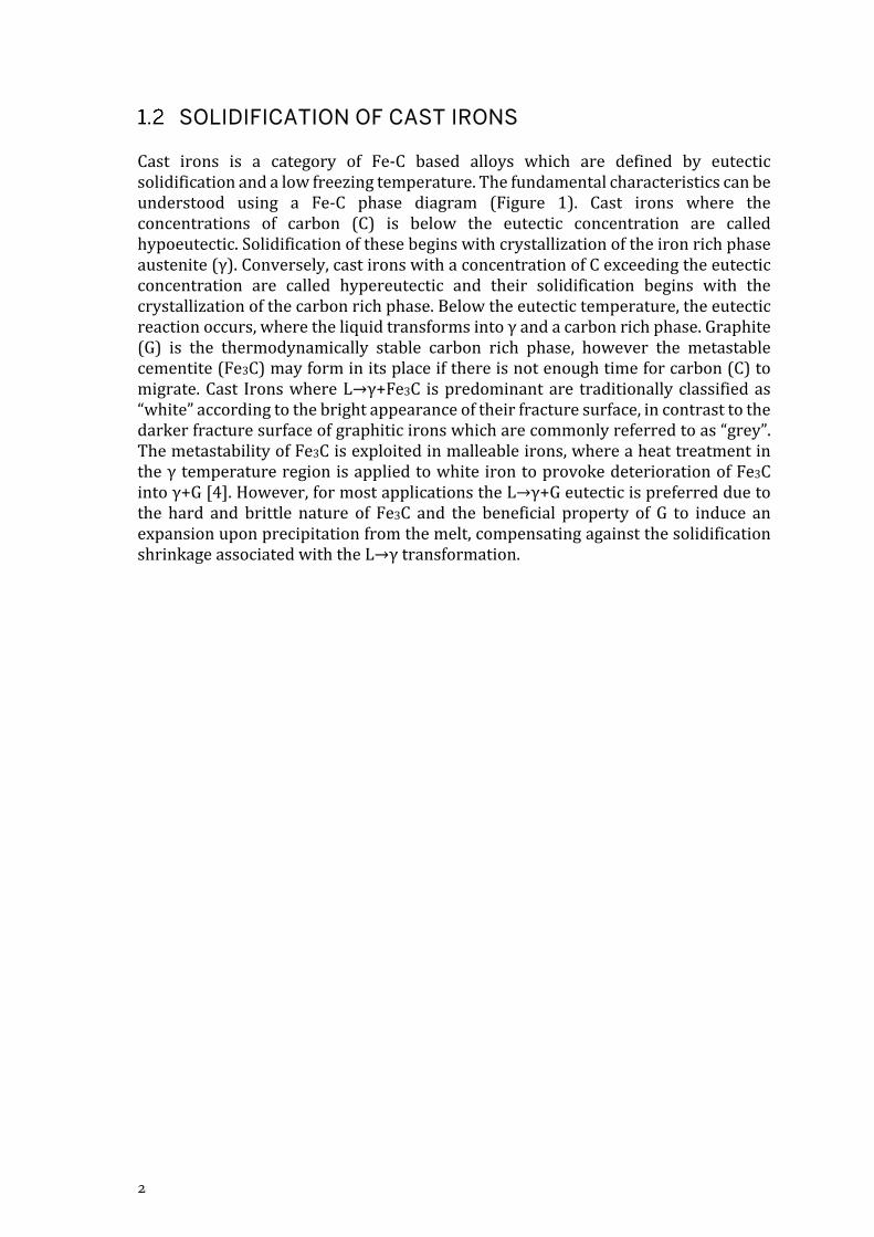
Cast irons is a category of Fe‐C based alloys which are defined by eutecticsolidificationandalowfreezingtemperature.Thefundamentalcharacteristicscanbeunderstood using a Fe‐C phase diagram (Figure 1). Cast irons where theconcentrations of carbon (C) is below the eutectic concentration are calledhypoeutectic.Solidificationofthesebeginswithcrystallizationoftheironrichphaseaustenite(γ).Conversely,castironswithaconcentrationofCexceedingtheeutecticconcentration are called hypereutectic and their solidification begins with thecrystallizationofthecarbonrichphase.Belowtheeutectictemperature,theeutecticreactionoccurs,wheretheliquidtransformsintoγandacarbonrichphase.Graphite(G) is the thermodynamically stable carbon rich phase, however the metastablecementite(Fe3C)mayforminitsplaceifthereisnotenoughtimeforcarbon(C)tomigrate.Cast IronswhereL→γ+Fe3C ispredominantare traditionallyclassifiedas“white”accordingtothebrightappearanceoftheirfracturesurface,incontrasttothedarkerfracturesurfaceofgraphiticironswhicharecommonlyreferredtoas“grey”.ThemetastabilityofFe3Cisexploitedinmalleableirons,whereaheattreatmentintheγtemperatureregionisappliedtowhiteirontoprovokedeteriorationofFe3Cintoγ+G[4].However,formostapplicationstheL→γ+Geutecticispreferredduetothe hard and brittle nature of Fe3C and the beneficial property of G to induce anexpansionuponprecipitationfromthemelt,compensatingagainstthesolidificationshrinkageassociatedwiththeL→γtransformation.

On the Solidification of Compacted and Spheroidal Cast Irons
3
Figure1.StableandmetastableFe‐Cequilibriumphasediagram[4].
Topromotethestableeutecticunderpracticalcoolingconditions,graphiticcastironscontain at least one graphitizing agent, typically Silicon (Si). Alloying elementsbelongingtothiscategoryhavetheeffectofsuppressingthemetastableeutecticbylowering its equilibrium temperature relative to the stable eutectic [5]. Similarly,elementswhichhave theoppositeeffectarecategorizedascarbidestabilizers [5].SomealloyingelementshavetheeffectofreducingthesolubilityofCinγandtherebylowertheeutecticconcentrationofC.Sincehigherordersystemsaremorecomplexanddifficult torepresentgraphically, thegeneralcharacteristicsof thesystemareoftenapproximatedbysubstitutingCbyacarbonequivalent(CE)inthebinaryFe‐Cdiagram, where CE is commonly calculated as /3 [4]. Aftersolidification is completed, the γ normally undergoes a solid‐state transformationintoferrite(α)+Gbeforeambienttemperatureisreached,whereGgenerallygrows

4
onexistingparticles.Again, themetastableFe3Cmayform, leadingtothereactionγ→α+Fe3C+G,resultinginfinematrixmicrostructureslikepearliteorbainite.Similartographitizingagentsandcarbidestabilizers,alloyingelementscanbecategorizedasferriteandpearlitestabilizers,whichpromoteferriteandpearliterespectivelyasproductofthesolidstatetransformation.
NUCLEATION
Onceaphaseisstableaccordingtothethermodynamicequilibriumdiagram,itdoesnotnecessarilyform.Thereasonisthatthehighcurvatureofasmallcrystalleadstoapressuredifferencethatlowersthemeltingpointofthecrystal.Thismeansthatfora given undercooling of the liquid, there is a critical radius of a spherical crystalbeyondwhichgrowthofthecrystalisfavoured[6].Thisrestrictionisoftendescribedasabarriertonucleationwhichmustbesurpassedbyundercoolingoftheliquid.Anabnormally largeundercooling is requiredbeforea crystalof thecritical radius isprobable toarrangespontaneously in the liquid fromthermal fluctuations.This isbecause,underpracticalconditions,themoltenmetalisincontactwithamouldorcontainerandcontainsinclusionsandimpurities.Thecontactbetweenthemeltandothercrystallinesurfacesfacilitatesnucleation[6].Thisisknownasheterogeneousnucleation.Themoresimilarthecrystallographiclatticeandtypeofbondingisoftheexistingcrystaltothenucleatingcrystal,thesmalleristhebarriertonucleation[6].The compatibility between two crystal lattices can be estimated using the planarlattice disregistrymodel [7],which has been used by researchers to theoreticallypredictwhichphasesaremosteffectiveasheterogeneousnucleationsitesforG.
Aninitialpopulationofpotentialnucleationsitesremainsasthechargematerialismelted[8].Melttreatmentlikeinoculationandgraphitemodificationintroducesnewparticles to the population [8]. The number and potency of the population iscontinuouslyevolvingdependingone.g.holdingtimeandtemperature[8].
For almost a century, foundries have treated the cast irons melts with variousadditionsforvariouspracticalbenefits.Today,anumberofcommercial inoculantsareavailable.MostarebasedonFeSi[9]butcontainadditionsofe.g.Zr,Ba,Sr,Ca,Al,Ti,Mnandrareearthelements(RE).Astudyemployingadropletemulsiontechniqueto studynucleation in cast irons showed that large undercoolingwas required tonucleateGinthepresenceofγ,howeverlowundercoolingwasrequiredtonucleateγinthepresenceofG[10].TheasymmetrywasproposedtorelatetothehighL‐Ginterfacialenergycomparedtoγandmelt.Animplicationisthatinordertoinoculatetheγ‐Geutectic, inoculationofG issufficientsinceγtheneasilynucleateonG.AnexperimentonanFe‐3.87wt%Calloyindicatedthattheundercoolingofγwas12‐17Kandwaslargerforhighcoolingrateandsuperheating[11].
1.2.1.1 NUCLEATION OF AUSTENITE
Literatureconcerning the inoculationofprimaryγ isrelativelyscarce.AdditionofSiO2 powder to molten hypoeutectic LGI has shown effective in increasing thenumberofγgrains[12].AnalysisofthelatticedisregistrysuggestedthatcrystallineSiO2waseffectiveinoculantbutSiO2glassisnot.Inalaterstudy,hypoeutecticLGIwasinoculatedwithSiC,SiO2andFepowder.Allthreeadditionscausedanincreaseinboth thenumberof equiaxedγgrainsand thenumberof eutectic cells [13]. Inagreementwiththelatticedisregistrymodel,theadditionofFepowdercausedthe

On the Solidification of Compacted and Spheroidal Cast Irons
5
strongestincreaseinthenumberofequiaxedgrains.Thecommercialinoculantsweremosteffectiveinincreasingthenumberofeutecticcells.
1.2.1.2 NUCLEATION OF GRAPHITE
Thenucleationofgraphitehasbeengivenmoreattentionbyresearchers.InastudyonthemechanismandfadingofFeSiinoculationtreatment,noSirichparticleswereobservedafteraslittleas15s,indicatingthatdissolutionoftheaddedinoculantisveryrapid[14].AconclusionofthestudyisthatFeSiisunlikelytobepresentatthestart of solidification, so the inoculating effectmust relate to secondary particleswhicharisefromtheadditionofFeSi,potentiallyfavouredbythesolutefieldaroundthedissolvingFeSi.ByquenchingmeltsimmediatelyaftertheadditionofvariousFeSibasedinoculants,thesolutefieldaroundthedissolvinginoculantwasinvestigated[15].With distance from the particle the Si content decreased and the C contentincreased.Closest to thedissolvingFeSi, tinySiCparticleswereobserved.FurtherawaytheSiCparticleswere larger,andsphericalorhemisphericalgraphitenucleiwere observed in contact with them. With increasing distance from this zone,graphitewasfoundwithoutSiC,andatransitionfromspheroidaltolamellarprimarygraphite occurred. A comparison between additions of FeSi and SiC showed thatadditionsofSiCismoreeffectiveforinoculation,resultinginsmallerundercoolingandhighereutecticcellcount[16].ForuninoculatedLGI,alowMn:Sratiohasbeenfoundtoreduceundercoolingandincreasethenumberofeutecticcells,aswellascontrolling the graphite shape and avoiding metastable eutectic [17]. MnS aresometimesfoundlocatedatthecentreofγ‐LGeutecticcells[18].ThespherodizingtreatmentappliedtoproduceSGIandCGIreactstronglywithOandS.Consequently,thechemistryofthemeltisquitedifferentbythetimeitistreatedwithinoculation.Inarecentstudy,inclusionswerefoundin38%outofthe2456investigatedgraphitespheroids.Consideringthatsomeofthespheroidswerelikelysectionedsuchthatthecentrewasvisibleorincluded,thetruenumberislikelyhigher.Thecompositionwasfound tovarystronglybothwithinandamong theanalysedparticles,andvariouscompounds were found in contact with the surrounding graphite. On average,particlesmostlycomprisedMgS,MgO,Ti(C,N),and(Mg,Co)(O,S).Inoculationchangedthe proportions of the phases in the particles. In an investigationwhere SGIwasproducedbyadditionsofMgandRE,theaddedelementsinvaryingproportionsalongwithSwerefoundconcentratedinthecentreofthegraphitespheroids[19].Thebasalplaneofthegraphiteappearedmoreorlessparalleltothecore,formingconcentricrings around it. The same authors also argue that spheroidal, compacted andexploded graphite all nucleate and grow in a similar fashion at an early stage,howeverthelattertwoeventuallydegenerateintosaidshapes,wheregrowthonlyproceeds on certain segments of the sphere. The efficiency of small additions ofelementslikeCainincreasingthenumberofeutecticcellshasbeenproposedtotheformationofsalt‐likecarbideswhichcontainsconvenientlyarranged molecules,whichwouldmakeaneasystartingpointforgraphitetoform[20].
The effect of the inoculation treatment is known to fade over time. It has beenproposedthatthisisaconsequenceofaphenomenoncalledOstwaldripening,whichleads to growth of large particles by dissolution of smaller particles, andconsequentlyareductionofthenumberofparticles.However,othershaveproposedthat the active substrates are only stable during the brief time the added FeSiparticlesaredissolving,afterwhichtheythemselvesbecomeunstableandbeginto
6
dissolve[15].REelementshavebeenproposedtoslowdownthefadingprocessbyforming an oxide film which protects the substrates against dissolution. AnexperimentwhereSGIwassolidified inapressurizedAratmosphereshowedthatincrementallyincreasingthepressurefrom1to145atmfirstreducedthenumberofgraphite spheroids, and then increased the amount of chill [21]. Low pressurestherefore appear to facilitate nucleation of graphite. The number of eutectic cellsuponsolidificationdropswithincreasedholdingtimeofthemeltbeforepouring[22].The rate of the drop increases with elevated holding temperature [22]. Highconcentration of S in the melt tended to reduce the rate of the drop, increaseundercoolingandnumberofeutectic cells, andresult in coarser flakes [22]. Sinceinoculationisexpectedtodecreasetheundercooling,notincreaseit,additionofSwasproposedtoincreasethenumberbyothermeans,suchasbyslowingthegrowthofeutecticcells.
PRIMARY AUSTENITE
In hypoeutectic cast irons, the primary solid phase is γ, which normally growsdendritically.Accordingtogeneraltheoryregardingdendriticgrowth[23],thesolid‐liquid interface becomesunstablewhenperturbations are favoured to grow.Thisconditionarisesduetothermalandsolutegradientsaheadoftheinterface.Forcastirons,theanisotropyofthefacecenteredcubic(FCC)γcrystalpromotesgrowthinorthogonaldirectionswhereatomsaremoreprobabletoattach.Whenagrowingγcrystalsuspendedinthemeltreachacertainsize,primaryarmsdevelopalongthesixorthogonaldirectionsdependingontheorientationofthecrystal.Behindthetipoftheprimaryarms,secondaryarmsbranchoffwithregularspacingintothefourfreefavoureddirections.Theaveragespacingbetweensecondaryarms(SDAS)isacommonmeasureofthecoarsenessorscaleofthedendriticstructure.Tertiaryarmsmayinturndeveloponthese,andsoon[24].However,thefirstgrainsoftendevelopclosetothesurfaceofthecastingwherenotallgrowthdirectionsarefree.γgrainsoriginating from the surface undergo spatial competitionwhere grainswhich areoriented such that a preferred growthdirection ismore alignedwith the thermalgradientarefavoured.Thesecrystalstaketheleadandobstructsthegrowthpathoflessfavourablyorientedcrystals,resultinginazoneoflonggrainsdominatedbythefavouredorientations.Thiszoneisoftenreferredtoasthecolumnarzone.Heat istransportedfromthemelttotheexteriorthroughthegrains.Ifthemeltinsidethecolumnarzonebecomesenoughundercooled,additionalγgrainsmaynucleateonsubstrates suspended in the melt, which then obstruct the growth path of thecolumnarzone.Thisprocess is referred toas thecolumnar‐to‐equiaxed transition(CET).Incontrasttothecolumnargrains,thecrystalssuspendedinthemeltarefreetogrow inall sixof the favouredgrowthdirections.The lackofconnection to theexteriormeans that theydonotassist inheatextraction.Thereleased latentheatrelated to their growth therefore must be transported through the liquid to thecolumnarzone.Theequiaxedgrainsgradually impingeononeanother,restrictingeachother’sgrowthpaths,andformacoherentstructure[25].AnexperimentonanFe‐3.87wt%Calloyindicatedthathighsuperheating,holdingtime,andcoolingrateresultedinalargerundercooling,athickercolumnarzone,andasmallernumberofγgrains[11].Whiletheinfluenceofsuperheatingandholdingtimecanbeattributedtoareductionofpotentheterogeneousnucleationsites,thecorrelationwithcoolingrateandundercoolingislessintuitive.Thesameauthorsproposethathighcooling
On the Solidification of Compacted and Spheroidal Cast Irons
7
rateleadstoasteepthermalgradientwhichcausesthecolumnarzonetogrowatahigherrate.Thethicknessofthecolumnarzonehasbeenreportedtovarydependingon typeof inoculant added to anLGImelt [26]. Following the endofdendrite tipgrowth, cooling causes the volume fraction of primary γ ( ′ ) to increase bythickeningofthearms. ′hasbeenreportedtobeneartheequilibriumvalueforawiderangeofcoolingrates[27].Otherssuggestthatitispossibletoincrease ′byadding elements which either suppress the graphite nucleation or promotenucleationofγ[28].Aslongasthedendriticstructureisincontactwithliquid,itissubject to phase coarsening which causes morphological changes [29]. Thedependenceofthechemicalpotentialonthecurvatureofthesolid‐liquidinterfacedrives solute and heat fluxes through the melt between high and low curvatureregions. This causes high curvature regions tomelt and low curvature regions togrow.Theaverageeffect isareductionof the totalsurfaceareaof thesolid‐liquidinterfaceandanincreaseintheoverallscaleofthesolidstructure,approximatelyinproportiontothecubicrootoftime.ForLGIunderisothermalcondition,SDAShasbeenconfirmedtofollowthisrule[30].Thesamestudyshowsthatwhensubjectedto extended period of phase coarsening, the structure begins to disintegrate anddisplace,leadingtoalessuniformdistributionofsolidinthecasting.
PRIMARY GRAPHITE
The graphite crystal comprises consecutive layers of graphene. Graphene is amonolayer of C atoms bound together in hexagonal patterns by covalent bonds.However, eachgraphenesheet isbound to itsneighboursbyweakvanderWaalsforces, whichmakes them easily slip or detach from one another. This has beenproposedtoinfluencethegrowthofgraphitebothintermsofprobabilityofcarbonattaching to the basal plane compared to the edges and by allowing the graphitecrystal to bend by having the layers slip in relation to one another [17]. Inhypereutectic alloys, graphite is the primary solid phase. Primary graphite isgenerally consideredundesirable incast irons,because itprovidesexpansionatastage of solidification when it is least needed, while having an adverse effect ontensileproperties in the finalcasting. Ithasbeenshownthatsolidificationofhighpurity hypereutectic cast irons results in nodular graphite, whether the purity isachievedusinghighpuritychargematerialorbyapplicationofvacuumdegassingtreatment [31, 32].Nodular graphite is therefore oftendescribed as the “natural”shapewhich arise in the absence of interference from impurities and γ. Thehighinterfacial energy between graphite and pure Fe‐C melt has been proposed toencouragetheparticletominimizeitssurfacearea,likeadropletofoilinwater,whilethemorecommon flake‐likegraphitemorphologieswereproposedtoberesultofsurfaceactiveimpuritiespresentinthemeltwhichreducetheL‐Ginterfacialenergy[33].Surfaceactiveelements(surfactants)aredescribedashavingweakattractiontotheliquidsolvent,hencemigratingtoitssurfaces.Theirtendencytoconcentrateonthesurface,contributestoaweakeningoftheattractionbetweenthesurfaceandthe bulk of the liquid, which lowers the interfacial energy [31]. The reducedinterfacialenergydecreases the “cost”ofnewsurfacearea,makingmorecomplexshapesofgraphite lessunstable.Sessiledropexperimentshave indicated that thesurfacetensionbetweenliquidironandagasisunaffectedbySiandC,howeverSandOtendtoconsiderablydecreasethetensionconsiderably.Swasfoundtobemoreinfluential,notbecauseOisa lesspotentsurfactant,butduetotherelativelyhigh

8
solubilityofSinliquidironcomparedtoO[31].ItwasproposedthatthespherodizingeffectofelementslikeMgandCerelatestotheirtendencytoscavengethemeltforSandObyformingstablesulphidesandoxides.Ithasbeenshownthatasanimpuremeltisincreasinglypurified,theprimarygraphitemorphologychangesfromstraightplates, to increasingly curved plates, and eventually to spheroids [32]. A laterexperimentindicatedthattheinterfacialenergyishigherbetweenthemeltandtheprismplaneofthegraphitethanthebasalplaneinMgandCetreatedmelts[34].Smainlyinfluencedtheinterfacialenergybetweenmeltandtheprismplane,reducingitbelowthatofthebasalplane,potentiallypromotinggrowthinthisdirection[34].Thesameauthorproposedthatthetransitionfromnodulartolamellargraphitecanbeexplainedbygraphitegrowingalongthecrystallographicdirectionswhichhavethelowestinterfacialenergyagainstthemelt.Swasreportedtobefoundadsorbedontheprismplanesbutnotonthebasalplanes,whichwasproposedtoexplaintheanisotropicinfluenceofSontheinterfacialenergy.Laterexperimentsshowsimilarresults[35].LatertheoryproposesthatimpuritieslikeOandSareadsorbedontheprismfaces,causinganatomicallyroughinterfaceasevidencedbythetransitionfromfacetedtomoreroundedstructureoftheprismsurfaceofthecrystal[36].
Anumberofgrowthmechanismshavebeenproposedtoexplainhowgraphitemaydevelopaspheroidalshape.Theoriesmainlybedividedintotwocategories.Thefirstacceptsthatthepreferredgrowthdirectionasnormaltothebasalplane[35,37].Thesecondconsidersthenucleationofanewlayeronthebasalplaneunlikelyduetotheweakcohesion,suggestingthatadditionallayersformbyexistingsheetsextendingover themselves through various mechanisms [32, 38‐40]. A number of otherelements have been reported to influence graphite shape similar to O and S,sometimesreferredtoas“subversiveelements”e.g.Bi,Pb,Sb,Te,Sn,AsandSe[17].Ce has shown to bemore effective thanMg in neutralizing the influence of theseelements[17].CombiningMgwithatraceamountofCeandasmallamountofTihasshown towiden the rangewheregraphite is compacted.The reasonCe facilitatescontrolofCGthanMghasbeenproposedtobethatthevolatileMgevaporatesovertime,raisingtheimpuritylevel,whileCemoreeasilystaysinsolution[36].NhasbeenproposedtodistortthelatticeofGbysubstitutingthepositionsofC[41].
GROWTH OF THE AUSTENITE-GRAPHITE EUTECTIC
Uponprecipitationoftheprimarygraphite,carbonisdrainedfromtheliquid,raisingtheequilibriumtemperatureforγ.Similarly,carbonisrejectedintotheliquidduringcrystallizationofprimaryγ,raisingtheequilibriumtemperatureforgraphite.Inbothcasesthemeltwillreachaconcentrationandtemperaturewherebothsolidphasesarestable,nucleated,andbegintocrystallizebyexchangeofsolutethroughtheliquid.SincethegrowthofgraphitereliesonthediffusionofCtoitsinterface,andthegrowthofγreliesontherejectionofC,theirexchangeallowsforacceleratedgrowthofbothphases [23]. Dendritic γ, by appearance indistinguishable from primary γ, is alsofound in hypereutectic cast irons [42‐44]. This has been described as an initialeutecticstagewherebothphasesgrowseparatedfromoneanotherintheliquidandthe exchange of solute occurs over relatively wide distances [42‐44]. Thisphenomenon is sometimes referred to as divorced eutectic or off‐eutectic [45].Researchers have attempted to explain this using the concept of a coupled zone,whichisdefinedasazoneinthetemperature‐compositionspaceinwhichgraphite

On the Solidification of Compacted and Spheroidal Cast Irons
9
andγarefavouredtogrowinacoupledmanner[28,46].Thebarriertonucleationofthesecondarysolidphaseallowsforcontinuedgrowthof theprimarysolidphasebelow the equilibrium eutectic temperature, shifting the composition of themeltacrossandovertotheoppositesideofthecoupledzone.Oncethesecondaryphasenucleates,itmaythengrowdivorcedfromtheprimaryphaseuntilthecompositionofthemelthasdriftedbackintothecoupledzone.Thephenomenonisproposedtobepromotedbytheasymmetryofthecoupledzoneincastirons,whereittendstobebiasedtowardstheextrapolationoftheγliquidus[46,47].Ithasbeenproposedthatsince the growth of each solid phase is favoured by proximity of the other, theirinterfacesagainsttheliquidareencouragedtogrowtowardsoneanotherandmeet[48]. Floatation and convection of graphite has also been proposed to promoteencountersbetweenthetwophases,assuggestedbytheaccumulationofspheroidsononesideofdendritearmsafterbeingsolidifiedundercentrifugaltreatment[49].Oncethisoccurs,triplejunctionsbetweenthetwophasesandtheliquidform,andcoupledgrowthmaycommence.However,theassumptionthatcoupledgrowthofγandGcommenceassoonasthephasesmeetisbysomeregardedtoosimple,asthephasesaresometimesobservedincontactwithoneanotherwithoutsignsofcoupledgrowth [50]. The cellular γ has been shown to adopt the crystallographic latticeorientationofthedendriticγ,meaningitcanbethoughtofasanextensionofthepriorγratherthanindependentcrystals[51,52].Themaininfluenceofthedendriticγonthe solid structure can therefore be regarded the interdendritic segregation ofeutecticandsolute.However,correlationsbetweenthecoarsenessofthedendriticγstructureandthesizeofeutecticcellshaveleadresearcherstosuspectthatitmayplayamoreimportantrole[26].ThecouplingofastronglyfacetedphaseGwithalessfacetedphaseγisexpectedtoresultsincomplexirregularstructures[23].
1.2.4.1 LAMELLAR GRAPHITE EUTECTIC
TheLG‐γcoupledeutecticgrowsoutwardsfromacentralpointinaroughlysphericalmanner[53].Theedgesoftheflakesleadthegrowthintotheliquid,withγgrowinga distance behind on its formerly crystallized surface [54]. The protrusion of thegraphiteedgeaheadoftheγmakessomeresearchersconsiderthelamellareutectictobelooselycoupled[36].Thethicknessoftheflakehasbeenobservedtoincreaseadistancebehindtheγfront,leadingtothesuspicionthatcarbonisnotonlyaddedtotheflakedirectlyfromtheliquidtothefrontedgesoftheflake,butcontinuestoaddtoitsthicknessbydiffusionthroughtheγ[53].Theflakesbend,twistandbranch,formingacomplexyetcontinuoussystemofgraphiteflakeswhichhasbeendescribedas“rosettes” [53,55]orcells [44]. Inoculationhasbeenreported tocauseamoreindented surface of the cells, with more γ in contact with the liquid, whileuninoculatedcellsaremoreround[25].Indentedappearanceoftheeutecticcellshasalsobeenshowntoappear forslowcoolingrates[56].Thetwocasesmayappearcontradictory, however a common denominator may be growth under smallundercooling. The scale of the cells is smaller than the scale of a dendritic grain,meaningeachdendriticgraintypicallyhostsmultiplecells[44].Thishas ledsomeresearcherstosuspectthatthepriordendriticstructuremayhaveaninfluenceonthedevelopmentofthelatereutecticcells[13,26,44].Slowcoolingproducescoarsergraphiteflakes[22].MorerecentobservationsofelevatedconcentrationsofSandOinLGandreduceddistancebetweengraphenelayersinLGcomparedtoSG,indicatethattheimpuritiesmaycontributetothelamellarshapebycrosslinkingthelayers
10
[57].Thecrosslinkingmayprovideresistancetorelativeslipofthegraphenelayersandhencetobendingofthecrystal.
1.2.4.2 SPHEROIDAL GRAPHITE EUTECTIC
SG‐γeutecticproceedsinaconsiderablydifferentmanner.γrapidlygrowsaroundthesphericalgraphiteparticles,formingashellthatseparatesthegraphitefromtheliquid.Thespheroidalgraphite(SG)thencontinuestogrowatamuchlowerratebydiffusionofCthroughtheshellofγ[49,55,58].Thismodeofsolidificationhasbeenproposedtobeaconsequenceoftheconditionsinthemeltbeingoutsidethecoupledzone,leadingγtogrowfasterthanthegraphiteandencapsulateit[46].Asthesizeofthegraphiteparticleincreases,theγshellmustexpandtomakeroomforit[59].Thishas been proposed to occur through creep by formation of vacancies at the L‐γinterfacewhichdiffusethroughtheshellandontotheγ‐Ginterface[50].Theelevatedconcentrationof vacancies in γwould allow formoreC todissolve, shifting the γliquidus line towardshigherC, leading toan increase in thevolume fractionratio/ .Theformationofmicroporeswereobservedashortdistancebehindtheendof
thesolidificationfront,whichwasproposedtoresultfromcondensationofresidualexcessvacancies.Moreover,theelevatedconcentrationofvacanciesisproposedtoexplainwhyaloweramountoflatentheatismeasuredforSGI[50].Theexpansionofthe graphite through plastic deformation of the surrounding shell is suggested totransfer onto the dendritic skeleton and onto the surrounding mould walls, incontrasttoVGandLGwheretheexpansionoccurincontactwiththemelt[60].TheslowgrowthbydiffusionofCthroughalayerofγhasalsobeenreportedtoexplainthehighnumberofeutecticcellscomparedtoLGIandCGI.Nucleationisassumedtocontinueuntilrecallescence,whichoccurswhenthesolidificationrateissohighthattherateofreleasedlatentheatexceedstherateofheatextraction.TheslowergrowthrateofSGandtheSG‐γeutecticconsequentlyallowsmorecellstonucleatebeforethisoccurs.Infact,thenumberofspheroidshasbeenreportedtoincreasethroughoutthesolidificationrange,indicatingthatthisneveroccursinSGI[58‐60].Thecontinuousthickening of the γ shell, leading to longer diffusion distances, is proposed tocontributetothisphenomenon[60].
1.2.4.3 COMPACTED GRAPHITE EUTECTIC
SimilartoLG‐γeutectictheCGgrowscoupledwithγwiththefrontincontactwiththemelt[61].Observationssuggestthat,unliketheLG‐γeutecticwherethegraphiteedgeprotrudesintotheliquidaheadoftheγ,theγistheleadingphaseduringgrowthof the CG‐γ eutectic [62]. Growth of the graphite is hence constrained by theprotrudingγ. In somecases,onlya thin liquid channel isobserved in frontof thegrowing graphite [62]. These channels are proposed to remain open due topartitioningwhichcauses local freezingpointdepression,meaning traceelementslikeTi,Bi,SbandSnmayhelpkeepingthechannelsopen[62].However,moresimilartoSG,thegraphiteisreportedtopredominantlygrownormaltothebasalplaneofthecrystal.ThemorphologymaybeachievedbyadditionsofnodularizerslikeMg,Ceand La [63], by high purity charge material, or by vacuum degassing [64]. Thisindicatesthatnodularizers,asforSGI,mainlyplayanindirectroleintheshapingofgraphiteby scavenging themelt of impurities.Moreover, it appears thepreferredgrowth direction appears only as important to CG as its influence on the overallgrowth velocity of G relative to that of γ. The L‐G interfacial energy has been

On the Solidification of Compacted and Spheroidal Cast Irons
11
estimatedtobefairlyequal fortheprismandbasalplaneofGformeltconditionsresultinginCG.CGhasbeenshowntobesensitivetocoolingrate,wherethinsectionsoften shown higher nodularity [36]. This has been proposed to relate to highundercooling,causinganelevatedfrequencyoflatticedefectsinthegraphitecrystal,promotingspiralgrowthnormaltothebasalplane[36].
DOUBLE POPULATION OF EUTECTIC CELLS
The size distribution of SG in eutectic and hypereutectic SGI is often found to bebimodal. In hypereutectic SGI the larger mode is explained as primary graphite,wherethelargersizeisattributedtotheprolongedgrowthindirectcontactwiththeliquid[58].Sometimes,thedistributionclosetothesurfaceofthecastingisreportedtobeunimodal,whiletheinteriorisbimodal[65].Apartfromtheirsize,thesetoflargerspheroidsisassociatedwithhigherconcentrationofSiandashellofferrite,whilethesetofsmallerspheroidsarereportedtomorefrequentlybeembeddedinpearlite, display little or no aura of elevated Si concentration, and be located inregionslatetosolidify[42,66,67].Athird,smallermodehasbeenreportedtoappearinheavysections[65,68].Thephenomenonofdifferentsizegroupsofeutecticcellsis not exclusive to SGI. Bimodal size distribution of spheroids has been observedqualitatively in CGI [67, 69]. A set of smaller LG‐γ eutectic cells has also beenrecognizedinLGI[70‐73].Inthiscase,thelargereutecticcellsarenotassociatedwithprimarygraphiteasthisisexpectedtoformeasilyrecognizedlargestraightgraphiteplates.Insteadthesmallersubpopulationisproposedtobeexplainedbyasecondarynucleationeventduringalatestageofsolidification.Thenucleationisproposedtooccur due to impingement of the eutectic cells, which increasingly limits thesolidificationrate.Thelastliquidthencoolsduetothelowreleaserateoflatentheat,leadingtoundercoolingexceedingthepreviousmaximumlevel,activatingadditionalnuclei[70].Segregationofsoluteelementsisalsoconsideredanimportantfactortopredict secondary nucleation events since partitioning causes the equilibriumeutectictemperaturetoshiftconsiderablyneartheendofsolidification[71].
MICROSEGREGATION
Duringfreezingofalloys,thesoluteelementsdistributebetweenthesolidphasesandtheliquid.Thisprocessiscalledsolutepartitioning.Theratiooftheamountofsoluteoneachsideofaninterfaceofapairofphaseswhichareinequilibriumiscalledapartitioncoefficient[74].Thepartitioncoefficientdependsontemperature,pressureandcurvatureoftheinterface[74].Undertheassumptionthatthesystemisinfullequilibrium,thepartitioningmaybedescribedusingthetraditionalleverrule[75].However,inmostpracticalsolidificationscenarios,equilibriumonlyholdstrueoverthe interface [76]. Due to the lowmobility of solute in solid, partitioning leavesconcentrationprofiles in thecrystal.Undertheassumptionofzeromobility inthesolid, infinitemobility in the liquid,equilibriumover the interface,andaconstantpartitioncoefficient,theprofilecanbecalculatedusingtheGulliver‐Scheilequation[77,78]. Inmostcases, solutedistribution isexpected to fall somewherebetweenthesetwoextremes.Predictingintermediateconditionsismorecomplicatedsinceitrequiresknowledgeoffactors likesolidificationtime,diffusionrate,diffusionpathlength,andcrystalgrowthrate,makingitnecessarytocombineitwithsomelevelofmicrostructuremodelling [79]. For finite diffusion rate in the solid, the profile is

12
subjecttohomogenization,leadingtosomesolutediffusingbackacrosstheinterface,aphenomenoncalledback‐diffusion[75].ThiscanbeapproximatedusingtheBrody‐Flemings model, which complements the Gulliver‐Scheil model with a coefficientcalculated fromthesolutediffusivity, solidification time,anddiffusionpath length[75]. For finite rate diffusion in the liquid, solute profiles develop ahead of thegrowinginterface[80].Inthiscaseaneffectivepartitioncoefficientisusefultodefineastheratioofsoluteconcentrationinthesolidclosetotheinterfaceoverthesoluteconcentration in the liquid far away from the growing interface where theconcentration can be assumed uniform due to convection [74, 80]. Unlike theequilibriumpartitioncoefficient,theeffectivepartitioncoefficientalsodependsonsolutetransportinthemelt[80].Forextremecrystalgrowthrates,equilibriumovertheinterfaceisbroken,becausethereisnotenoughtimeforsolutetopartition,andends up locked in the crystal lattice, a phenomenon called solute trapping [81].Experimental and theoretical work on Fe‐C‐X suggest that the tendency ofgraphitizingalloyingelementstoconcentrate inthesolidγduringsolidificationofcastironsrelatesmainlytotheirinteractionwithC[5,82].Forlowcarboncontents,i.e.steels,graphitizingandcarbidestabilizingelementsbothconcentrateinthemeltduringsolidification[5,82].Forincreasedcarboncontents,therepulsiveinteractionbetweengraphitizingelementsandCforcesthemoutoftheCrichmeltandintotheγ[5,82].Conversely,theattractiveinteractionofcarbidestabilizingelementswithCpullsthemintotheCrichliquid,loweringtheirpartitioncoefficient[5,82].Inpractice,cast irons contain a largenumber of alloying elements,making partitioningmorecomplex.SegregationwasinvestigatedinSGI,notingthattheareasaroundSGwasenrichedwithSi,NiandCu,whilethelast‐to‐freezeareaswereenrichedwithMn,Mo,Cr,Va,TiandPb[83].InapoorlyinoculatedSGI,largertroughsoflowSiwerefoundandcoincidedwithpeaksofhighMnconcentration[83].InnormallyinoculatedSGI,suchcharacteristicswerelimitedtotwosmallspots.TheslowgrowthmodeoftheSG‐γ eutectic and poor inoculation was proposed to contribute to strongersegregation.InalaterstudyonSGIwithasolidificationtimeofabout30seconds,theeffectivepartitioncoefficientsweremeasuredandfoundtocorrespondroughlytothose measured and analytically determined for ternary Fe‐C‐X alloys [84]. ThemeasuredevolutionofSi,Mn,Mo,andCrinthesolidclosetotheS‐LinterfaceversusfractionsolidwasfoundtoagreeroughlytosoluteprofilescalculatedbyapplicationofthemeasuredeffectivepartitioncoefficienttotheGulliver‐Scheilequation.NiandCudisplayedworseagreement.UsingtheBody‐Flemingsmodel,theassumptionsofzerodiffusioninsolidandinstantmixingintheliquidwerefoundtobereasonablefortheconditionsoftheexperiment.Laterworkbythesameauthorsbraughtfurthersupporttotheseconclusions[85].SoluteprofilesofSiandMninγasafunctionoffractionsolidwasestimatedusingEPMAinanSGIquenchedsoonaftersolidificationwas finished and compared to simulated profiles. The simulationmade the samegeneral assumptions as the Gulliver‐Scheilmodel, but applied a temperature andcomposition dependent partition coefficient for Si and a composition dependentpartition coefficient for Mn. The simulated profiles agreed reasonably with themeasuredprofiles.
KNOWLEDGE GAPS
TheaboveliteraturesurveyshowthatmuchisalreadyknownaboutsolidificationofCastIron,howeversomeareasremainunclear.Mostresearchhasrevolvedaround

On the Solidification of Compacted and Spheroidal Cast Irons
13
theeutecticstageofsolidification,meaningtopicsrelatedtothedendriticγstructureand its influence on the later solidification is still rather unexplored.As has beenpointedoutbefore[44],theprimaryreasonforthisappearstobeitsobscurityinthefinalstructureandascarcityofknowledgeandmeanstocharacterizeit.Quenchingtechniqueswas formanyyears theprimarymeanof studying thestructure.Morerecently researchers began to exploit the segregation of Si using colour etchingtechniques to qualitatively reveal the early solidification structure [83]. Lack ofknowledge on how to characterize the structure has led to many subjective andambiguousdescriptions,making itdifficult to interpretandcompareearlierwork.Recently, some useful parameters related to the structure were introduced [27],however thespreadof theirusehasbeen limiteddue to lackingunderstandingoftheir relevance and practical means to measure them. While the colour etchingfacilitatesqualitativeoverviewofthestructure,non‐uniformity inthecolouringofthe structure makes it difficult to apply image analysis on the rawmicrographs.Instead, image analysis is performed on binary images produced by manuallydrawingoverthemicrograph.Thereisariskthatthisintroducesbiasdependingone.g.theskillandjudgementoftheoperator.Thereisthereforeaneedforalternativeapproachestocharacterizationofthedendriticstructuretobeexplored.
TheSGparticlesinSGIhavereceivedextensiveattention,howeverthesamecannotbesaidforCGI,eventhoughtheyoftenmakeupaconsiderablepartofthestructure.ArecentresearchprojectrelatedtoshrinkageporosityformationinCGIfoundthatthedefectswereassociatedwithahighervolumefractionofSG,andinparticular,asubpopulationofsmallerSGwhichwereproposedtohaveformedatalatestageofsolidification.Thishascontributedtoaraisedinterestintheirnatureandroleinthematerial as well as the conditions in the last melt to solidify. The nucleation ofgraphiteinSGIisoftenobservedtocontinuethroughoutsolidification,whileinCGIitis regarded more discrete due to the higher growth rate leading to strongrecallescence.ItisthereforesuspectedthatthebalancebetweenSGversusCGisanimportantfactorforthesolidificationprocess,potentiallytriggeringlatenucleationof graphite. The change in nucleation behaviour is expected to influence the sizedistributionofgraphite.
Microsegregationofsoluteincastironshasreceivedsomeattention.However,castiron solidification models often make assumptions such as constant partitioncoefficients, zero diffusivity in the solid phase, instantaneousmixing in the liquidphase. It appears thedegree towhich thesearevalid formorepractical cast ironsolidificationscenariosisstillratherunclear.Theearlierexaminationsinvolve,forexample, a solidification time of 30 seconds, and in another case, immediatequenching after solidification.Moreover, the suspicion that the SG‐γ eutecticmayinfluencepartitioningofsoluteduringsolidificationisstilluntreated.IfSGleadstoadifference in the composition in the last melt to solidify, this could bring betterunderstanding of the solidification of SGI and the role of SG in CGI. Potentialmechanismscouldforexamplerelatetothecreepprocessoftheexpandingγshellwhich has been proposed to cause an elevated concentration of lattice defects.Substitutional elements diffusemainly through lattice defects, hence the elevatedconcentration could accelerate back‐diffusion. The elevated defect density is alsoproposedtoincreasethesolubilityofcarbonintheγandshifttheconcentrationinthemeltaccordingly.Thedependenceofpartitioncoefficientsonthecarboncontentmayshiftthepartitioncoefficients.Theconsiderablyslowergrowthvelocityofthe

14
SG‐γeutecticisalsoexpectedtoreducethesolutegradientsaheadoftheinterfacewhichmaybringtheeffectivepartitioncoefficientclosertotheequilibriumpartitioncoefficient.

On the Solidification of Compacted and Spheroidal Cast Irons
15
CHAPTER 2
RESEARCH APPROACH
CHAPTER INTRODUCTION
Thischapterdescribestheresearchmethodsusedinthisthesis.Thepurposeandaimare first described, followed by a description of research activities and researchmethods.
PURPOSE AND AIM
Asolidunderstandingofthesolidificationofacastmaterialisessentialinordertoforeseeundesiredfeaturesandpredictitsperformanceinoperation.ThisresearchoriginatesfromaparticularneedofproducersofcomplexcastironcomponentstoimprovethepredictivecapabilityofsimulationtoolswithrespecttomicroshrinkagedefectsinCGI.Theidentifiedweakpointinthetoolsislackingsolidificationmodelsfor the material. The aim of this research is to learn more about solidificationphenomenaassociatedwith the formationofmicroshrinkagedefects inCGI in thecontextof its closestneighbourSGI.Thenewunderstandingmay in the futurebeimplementedintosolidificationmodelsinasimulationsoftwareandhelpfoundriesavoidandremedycostlyproblemsrelatedtomicroshrinkagedefects.
RESEARCH DESIGN
Research perspective and strategy
Materials science is an interdisciplinary field in the intersectionbetweenphysics,chemistryandengineering.Physicsandchemistryarenaturalscienceswhichhavealongtraditionofempiricism,withemphasisonexperimentsandquantifiabledata.Falsifiability,validityandreliabilityarecommoncontrolcriteriaforevaluatingthefindings. Materials science concerns the understanding of how a material’scomposition and processing contribute to its structure, properties, and finally itsperformance.Forcastirons,thesolidificationprocessistypicallytheprimaryprocessdeterminingitsstructure.Itisthereforecrucialtounderstandthefactorsgoverningthematerial’ssolidificationandhowtheycontributetoitsstructure,propertiesandperformance.Thisworkfocusesonthesolidificationprocess.
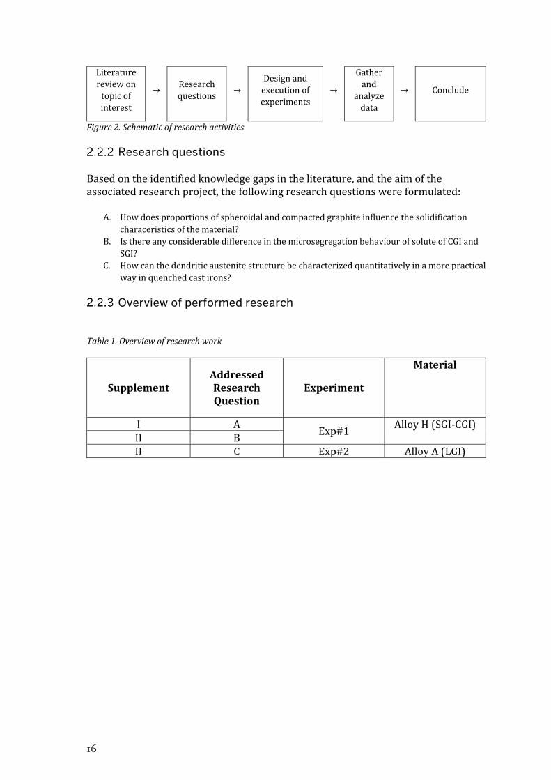
Theresearchstrategycanberoughlyrepresentedasfollowing.Theworkbegunwithaprocessofbecomingfamiliarwiththeresearchareathroughliteraturesurveyoncastironsandtheirsolidificationprocess.Knowledgegapswereidentified,andtopicsofinterestwerenarroweddownonthebasisoftheaimoftheassociatedresearchproject.Researchquestionswereformulatedandrefined.Experimentsweresetuptocomparetreatmentandresponse.ThisissummarizedinFigure2.
16
Literaturereviewontopicofinterest
→Researchquestions
→Designandexecutionofexperiments
→
Gatherand
analyzedata
→ Conclude
Figure2.Schematicofresearchactivities
Research questions
Basedontheidentifiedknowledgegapsintheliterature,andtheaimoftheassociatedresearchproject,thefollowingresearchquestionswereformulated:
A. Howdoesproportionsofspheroidalandcompactedgraphiteinfluencethesolidificationcharaceristicsofthematerial?
B. IsthereanyconsiderabledifferenceinthemicrosegregationbehaviourofsoluteofCGIandSGI?
C. Howcanthedendriticaustenitestructurebecharacterizedquantitativelyinamorepracticalwayinquenchedcastirons?
Overview of performed research
Table1.Overviewofresearchwork
SupplementAddressedResearchQuestion
Experiment
Material
I AExp#1
AlloyH(SGI‐CGI)II BII C Exp#2 AlloyA(LGI)
On the Solidification of Compacted and Spheroidal Cast Irons
17
MATERIALS AND EXPERIMENTS Materials
This work involves the two alloys listed in Table 2. Alloy H and Awere initiallyproduced in furan sand molds as hypereutectic SGI and a hypoeutectic LGIrespectively.However,noneofthesupplementsconcernthealloysintheirinitialcaststate.Bothalloysweresubjectedtoremelting,heat treatment,andresolidificationafter the initial casting. Focus will therefore here be on the latter process. MoredetailsontheinitialproductionofalloyHisavailableinsupplementsIandII.
Table2.ChemicalcompositionmeasuredusingOESonrapidlysolidifiedcoinsamples.CarbonequivalentCE=C+(Si+P)/3.
Alloy CE C Si Mn S P Cu Sn Mo Cr Mg Fe
H 4.76 3.86 2.59 0.64 0.01 0.03 0.84 0.1 ‐ ‐ 0.065 Bal
A 4.05 3.40 1.89 0.57 0.09 0.05 0.9 0.05 0.05 0.15 ‐ Bal.
SupplementIandIIarebasedonalloyHwhileSupplementIIItreatsalloyA.NotethatthecompositionofalloyAinTable2isthecorrectone,andnotthecompositiongiven in the printed or current published online version of the supplement. Acorrection of this has been requested to be included in a future erratumaccompanying the online version. The precise composition is however of minorimportancetotheconclusionsofSupplementIIIduetothenatureofitstopic.
The initialcastmaterialsofAlloyHandAweremachined toproducecylindersof400±0.5gandapproximatediameterofØ38mmforuseintheexperiments.
Experiment I
The experiment related to supplements I and IIwasdesigned toproduce varyingfractionsof spheroidalandCGranging fromSGI toCGI inorder to investigate thenatureandinteractionofthetwomorphologies.Thiswasachievedbyremeltingthematerialandsubjectingittovaryingholdingtimesbeforeitwasagainsolidified.Theremelting of a single alloy and subjecting it to variation in holding time wasconsidered preferable to direct variations in spheroidization treatment orsubsequentanti‐spheroidizationtreatment,becauseoftheeliminationofthemanyvariablesinvolved.Themachinedcylinderswereplacedinanaluminacrucibleinsideavertical tubeelectricalresistance furnace,restingonacolumnofgraphite inthecentralpositionbetweentheheatingelements.Arwasintroducedtothefurnacefromthebottomatarateof5l/min.Excessgasesescapedthroughasmallholeinthetop.Thefurnacewasprogrammedtorampupto1450°Cover75min,andthenholdfora time according to Table 3. 5‐10min prior to the end of the holding time, twothermocouplesprotectedbysealedquartzglasstubeswereintroducedtothefurnacewiththejunctionspositionedinthecenterandagainsttheinnersideofthecruciblewallataheight20mmoverthebottomofthecrucible.Bytheendoftheholdingtime,the furnace was shut off and left to cool down with the specimen inside. Theexperimentswereperformedoneperday.

18
Table3.Alias,furnaceholdingtime,andnumberofrepetitionsfortheexperimentrelatedtosupplementsIandII.
Alias H10 H20 H30 H40 H50 H60
Holdingtime[min] 10 20 30 40 50 60
Repetitions 4 3 3 3 3 3
Experiment II
The experiment related to supplement III was performed by the author inunpublishedworkwiththeintentofstudyingthephasecoarseningofthedendriticprimaryγstructure.Alackofliteraturerelatedtocharacterizationofthestructureand itsmorphological changes inspired supplement III.Details on the experimentwasscarceinthepaperduetoitsscope,soitwillbedescribedinmoredetailhere.Thebasicsetupwassimilar tosupplement IandII.Thekeydifference is in thatasecondwelltimewasimposedbetweentheprimaryandeutecticreaction,allowingphasecoarseningtoproceedunderconstanttemperature.Afterthesecondholdingtime,thespecimenwasquenchedtopreservethedendriticstructure.Inmoredetail,thefurnacewasprogrammedtorampupto1500°Cover90min,andholdingfor30min. Cooling curves were recorded in preliminary experiments to determine anappropriate temperature for isothermal treatment. The solidification time andtemperatureforcoherencyoftheprimaryγstructurewasapproximatedasthepointofmaximumdifferencebetweenthecentralandinner‐wallthermocouplespriortotheeutecticreaction.Afterthepreliminaryexperiments,thesameheatingprogramwasapplied,howeverasecondholdingtimewasimposedat1168°Cforadurationaccording to Table 4. By the end of the second holding time, the specimen wasquenchedinwaterbyremovingthemetalplatewhichsupportedthegraphitecolumnandcrucible,allowingittodropthroughthefurnaceintoawaterbathplacedbeneath.Thewaterwasagitatedusingawaterpumpduringthequenchingprocess.
Table4.Alias,secondholdingtimeimposedat1168°C,andthenumberofrepetitionsfortheexperimentrelatedtosupplementIII.
ExperimentID
B0 B30 B90 B180
Secondholdingtime
[min]0 30 90 180
Repititions 4 4 4 4

On the Solidification of Compacted and Spheroidal Cast Irons
19
CHARACTERISATION AND TESTING Sample preparation
Aftertheexperiments, thecylindricalcastingswerecuthorizontally20mmabovetheirbase,producingcircularsections.AlloyHwasmountedinbakelitewithacarbonfiller.AlloyAwasmountedinepoxy,theprimaryreasonbeingthattheepoxymoreeasily filled shrinkage cavities and cracks that frequently occurred during thequenchingprocedure.DuetothehighhardnessofthequenchedspecimensofalloyA,thetwomaterialsdemandeddifferentsamplepreparationschemes.
AlloyHwasmanuallygroundusingawaterlubricatedSiCpaperonarotatingdiscdown to a grit of P2000 FEPA. Each step had a grinding direction approximatelyperpendiculartotheprevious,andthegrindingproceededuntilscratchesfromthepreviousstephaddisappeared.Aftergrindingwascompleted,thespecimenswerepolishedusinga3µmdiamondsuspensiononanaplesssatinwovenacetatesurfaceand finalized using an oxide slurry on a porous neoprene surface. No systematicdurationofthepolishingstepswasfoundduetovaryingresults.Insteadthequalityof the surface was frequently controlled using an optical microscope, and thepolishingcontinueduntilthequalitywasjudgedgood.
AlloyAwasmanuallygroundonP80FEPASiCpaperuntilplanar.Therestof thesample preparation was performed in an advanced sample preparation system,beginningwithP220FEPAresinbondeddiamonddiskwithwaterlubricationinanuntilthedeepscratchesdisappeared,followedbyfinegrindingusing9µmdiamondsuspension for2minand30sec.Polishingwasperformedusinga3µmdiamondsuspensiononataffetawovenwoolclothsurfacefor3min.
Colour etching
ApicricacidbasedreactantdevelopedbyMotz[83]wasappliedtoAlloyHtorevealtheearlysolidificationstructure.Thereagentwasheatedto94°Candthespecimenwassubmergedwiththemetallicsurfacefacingdownwardswithaslightangle.Aninitial duration of 8 min was applied, followed by examination under opticalmicroscope.Ifrequired,thespecimenwasreintroducedtothereagentinstepsof3minuntilthedesiredcolouringwasachieved.
AnewcolouringtechniquewasdiscoveredanddevelopedtorevealthesolidificationstructureinalloyH.Thebasicprincipleistopolishusingacommercial1µmdiamondsuspension under low pressure. This causes the non‐cementite areas in theledeburitetocolour,producingacontrastbetweenareasthatwereliquidandsolidpriortoquenching.
Graphite characterization
ForalloyH,theareaandshapeofgraphitewasmeasuredquantitativelyusingopticalmicroscopyandcomputeraidedimageanalysis.Atleast40non‐overlappingimageswas captured for each cross section, with an objective lensemagnification of 5x,resultinginapixelsidelengthof1.081μm,correspondingtoanareaofatleast151mm2perspecimen.

20
The percent nodularitywasmeasured according to ISO 16112 [86] involving thecalculationofroundnessfromtheparticlearea andmaximumferretdiameter using equation 1 , followed by the calculation of the percent nodularity usingequation 2 ,where representstheareaofparticleswitharoundnessexceeding0.625,while represents theareaofparticleswitha roundnessbetween0.625and0.525.Particlesconnectedtotheedgeofthemicrographwereexcluded.
4 1
∑ 1
2∑
∑ 2
The area and roundness data for the graphite was also used to analyse the sizedistributionofSGinthespecimens.Inthiscase,theSGweredefinedasallparticleswitharoundnesslargerthan0.525.Duetothevaryingroundnessoftheparticles,theareaoftheparticleswasconvertedtoanequivalentdiameter 2 / .Thesizedistributionwasproducedbydividingtheparticlepopulationinto20sizeclassesofequal width, where the upper boundary of the largest class corresponded to theequivalent diameter of the largest SG. The sectional size distribution by numberdensitywasconvertedtovolumetricsizedistributionbyemployingafinitedifferencemethodbasedoncontinuoussizedistribution[87].Thenumberdensitieswerethenconvertedtovolumefractionsbymultiplyingbythevolumeoftheaverageparticleinrespectivesizeclass.Amethodforestimatingsubpopulationsmakingupthesizedistributionwas developed. In principle, the size distributionwas assumed to beconstructedofanumberofoverlappingsubpopulationsofGaussiandistribution.Thefunctionwasfittedtothemeasureddistributionusingaminimizationscheme,wherethesumofabsoluteerrorwastheobjectivefunction.
Primary austenite characterization
The volume fraction and surface area per unit volume of the primary γstructurewasmeasuredusingtwomainapproacheswhichwerecompared.ThefirstapproachinvolvedgenerationofbinaryimagesfromthemicrographswiththehelpofAdobePhotoshopCS6.Theparameterswerethenmeasuredautomaticallyusingthe commercial image analysis software Olympus Stream. The method is rapid,however some obvious differences between the binary images and the originalmicrographs were identified. To estimate how considerably these differencesinfluenced the values of the measured parameters, a second generation ofmeasurementsweremadewhere thedifferenceshadbeenmanuallycorrectedbycarefulcomparisontotheoriginalmicrograph.Moreover,thesameparametersweremeasured using traditional point counting and line interceptmethods. The pointcountingwasperformedbysuperposinga22x22squaregridovereachmicrographandcounting thenumberofpoints coincidingwith thedendrites.Pointson theboundarywerecountedseparatelyas ½.Thepointfraction wasthencalculated

On the Solidification of Compacted and Spheroidal Cast Irons
21
as 0.5 ∗ ½ / . The line intercept technique was performed bysuperposingthreeconcentriccirclesoverthemicrographandcountingthenumberof interception points ∅ between the circles and the dendritic structure. Thenumber of incercept points per unit circle length ∅ was then calculated as∅/ ∅. wasthencalculatedusingthestereologicalrelation 2 [88].
EPMA-WDS
Electron probe micro analysis was applied to alloy H in order to investigatemicrosegregation.TheinstrumentisamodifiedARL‐SEMQequippedwithsixWDSspectrometers.Itoperatesatanaccelerationvoltageof25kVandappliesasamplecurrentof6μA.ItwasemployedtomapthedistributionofC,Si,Mn,P,CuandSnovera300x300pointrastercoveringa3x3mmarea.TheconcentrationdatawaslatertreatedandvisualizedusingscriptsdevelopedinMatlab.
Partitioningwasinvestigatedbyestimatingtheequilibriumeutectictemperature ∗calculatedusingequation 3 ineachpointinthemetalmatrix(excludinggraphite).Thecompositioninthemetalmatrix / asafunctionofareafractionofthemetalmatrixwascalculatedbysortingthedatapointsindescendingorderof ∗.Foreachpoint, the average composition in the liquid was estimated as the averagecompositionof all pointswith a lower ∗.This allowed for estimationof effectivepartitioncoefficients asa functionofarea fractionof thematrix,accordingtoequation 4 .
∗ 1158.86 3.77 3.43 18.93 3.30 3
/
4

22

On the Solidification of Compacted and Spheroidal Cast Irons
23
CHAPTER 3
SUMMARY OF RESULTS AND DISCUSSION
CHAPTER INTRODUCTION
Inthischapter,theresultsaresummarizedanddiscussed.
THE TRANSITION FROM SPHEROIDAL TO COMPACTED GRAPHITE IRON
To support discussion of the results, this sections begins with remarks on theinfluenceoftheholdingtimeasameanstocontrolthenodularity, includingsomeunintendedinfluencesofthevariable.
The control of graphite morphology by varying holding time during remelting of SGI (Supplement I)
TheexperimentalseriesH10‐H60wasproducedbyremeltingandsolidifyingalloyHusing varying holding times. This resulted in varying fractions of SG and CG asindicated in Figure 3. The method was preferred due to the elimination of thevariables involved in direct variation of the spheroidization treatment,making iteasier to attribute characteristics to the graphite morphology. The main riskconsidered was that prolonged holding time would decarburize the melt. Themeasuredarea fractionssummarized inFigure4shownosignofdecarburization.Themeasured percentages of nodularity are summarized in Figure 5, showing aratherlineardecayofthevalue,withsomescatter.

24
Figure3.Selectedmicrographs,illustratingthetransitionfromSGItoCGIwithincreasingholdingtimeat1450°C.a:H10,b:H20,c:H30,d:H40,e:H50,f:H60.
Figure 4.Measured area fraction graphite as afunction of holding time. The dashed linesrepresentthetheoreticalfractiongraphiteforthealloy Assuming ferrite and pearlite matrix.Whiskersrepresent the95%confidence intervalforthemean.
Figure 5. Measured percent nodularity as afunctionofholdingtime.Whiskersrepresentthe95%confidenceintervalforthemean.
ExaminationofthecoolingcurvesinFigure6indicatessomeunexpectedinfluencesoftheholdingtime.Firstofall,themaximumtemperatureisslightlylowerforH10,meaningthemaximumtemperatureinsidethespecimenwasnotreachedduringthe10minholdingtime.Secondly,thereisaslightdependencyofcoolingrateonholdingtimeforH10‐H30.So,whiletheexperimentalmethodwassuccessfulincontrollingthe nodularity, it had some unintended influences which complicates theinterpretationoftheresult.Acloserexaminationoftheeutecticregionofthecoolingcurves (Figure 7) reveals some interesting characteristics. The eutectic reactionbegins at a higher temperature for H10. SGI is usually associated with higherundercoolingdueto its lowgrowthrate.The lowundercoolingofH10most likelyrelates to residual undissolved particles in the melt due to the lower maximumtemperatureandshortholdingtimeafterremelting.
0 10 20 30 40 50 60 70
Holding Time [min]
0
2
4
6
8
10
12
14
0 10 20 30 40 50 60 70
Holding Time [min]
0
20
40
60
80
100

On the Solidification of Compacted and Spheroidal Cast Irons
25
Figure 6. Central temperature duringsolidification of alloy H after remelting andholding time. is the calculated theoreticalgraphite liquidus, and is the theoreticalequilibriumeutectictemperature.
Figure 7. Central temperature duringsolidification of alloy H after remelting andholding time. The curves are offset in time tofacilitatedistinction.
Divorced and cellular eutectic growth (Supplement I)
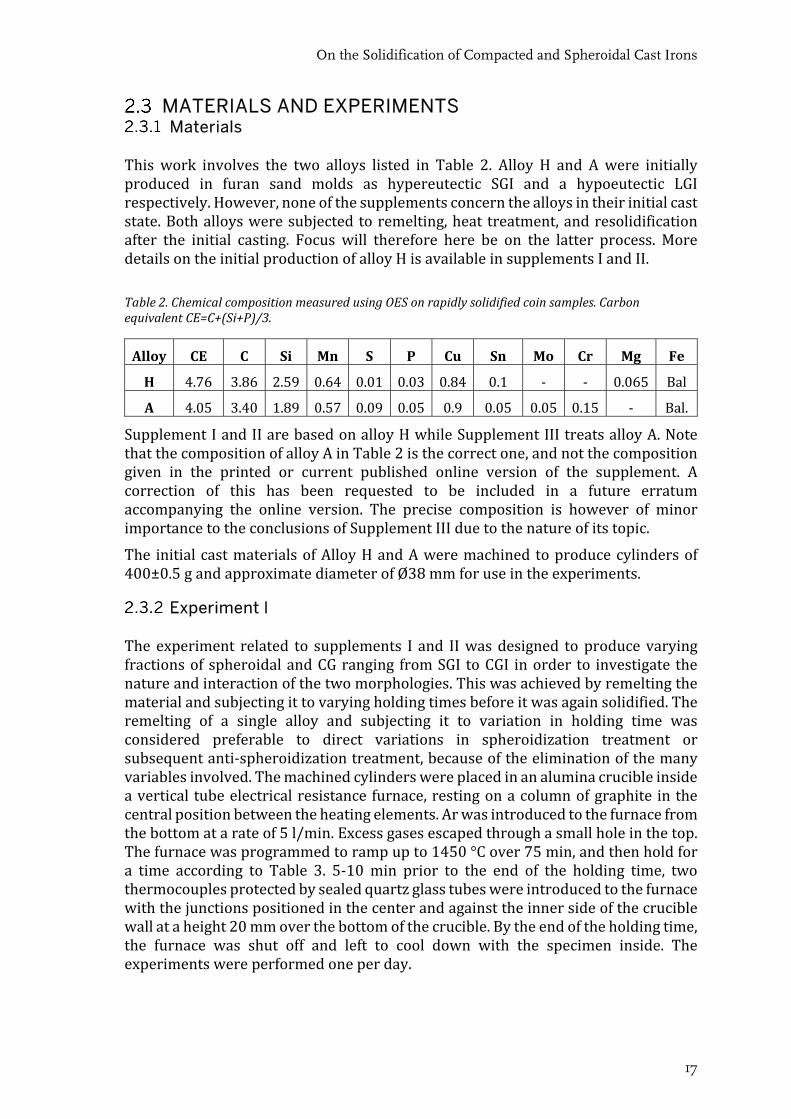
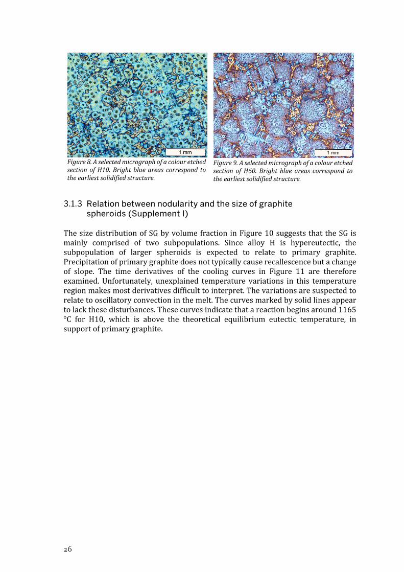
AllfourrepetitionsofH10inFigure7displaytwomaximaintemperatureduringtheeutectic reaction. H20 displays similar but less pronounced characteristics. OtherresearchershaveassociatedtheseparationoftheeutecticreactionintotwomaximaonthecurveinhypereutecticSGIwithaninitialstageofdivorcedgrowthofgraphiteand dendritic γ from the melt prior to cellular eutectic growth [89]. Using thisreasoning,considerablylessdendriteswasexpectedforlongerholdingtimeswhereonlyonemaximumwasrecognized.However,asubstantialamountofdendriticγwasobservedinallspecimensusingcolouretching,asindicatedbyFigure8andFigure9.Thisshowsthat,whiletheseparationoftheeutecticreactionintotwomaximaonthecoolingcurvesmayrelatetothedivorcedeutecticinSGI,divorcedeutecticoccursinCGIwithoutleavingobvioustracesonthecoolingcurves.Thereasonisprobablythatthe dual maximum occurs when the transition from divorced to cellular eutecticinvolvesadrasticreduction insolidificationrate,as isexpected forSGI.TherapidgrowthoftheCG‐γeutecticontheotherhandleadstoamoreseamlesstransitionbetweenthestagesintermsofsolidificationrate.
26
Figure8.AselectedmicrographofacolouretchedsectionofH10.Brightblueareas correspond totheearliestsolidifiedstructure.
Figure9.AselectedmicrographofacolouretchedsectionofH60.Brightblueareas correspond totheearliestsolidifiedstructure.
Relation between nodularity and the size of graphite spheroids (Supplement I)
ThesizedistributionofSGbyvolumefractioninFigure10suggeststhattheSGismainly comprised of two subpopulations. Since alloy H is hypereutectic, thesubpopulation of larger spheroids is expected to relate to primary graphite.Precipitationofprimarygraphitedoesnottypicallycauserecallescencebutachangeof slope. The time derivatives of the cooling curves in Figure 11 are thereforeexamined.Unfortunately, unexplained temperature variations in this temperatureregionmakesmostderivativesdifficulttointerpret.Thevariationsaresuspectedtorelatetooscillatoryconvectioninthemelt.Thecurvesmarkedbysolidlinesappeartolackthesedisturbances.Thesecurvesindicatethatareactionbeginsaround1165°C for H10, which is above the theoretical equilibrium eutectic temperature, insupportofprimarygraphite.

On the Solidification of Compacted and Spheroidal Cast Irons
27
Figure10.VolumetricsizedistributionofSGbyvolumefraction.H10‐H60correspondstoH10‐H60.
Figure11.Timederivativeofcentral temperature.Curves are grouped by holding time and offset intemperaturetofacilitatecomparison.Curveswhichdisplayednoisefortemperaturesabovetheeutecticreaction are dotted to emphasize the curvesdiscussedinthetext.
ThefeaturesofthedistributionwereinvestigatedquantitativelyusingcurvefittingascanbeseeninFigure12.ThisallowedforestimationofthetotalvolumefractionofeachsubpopulationofSG.Figure13shows,again, thatSG isdominatedby twosubpopulations, ∗ and ∗ , where ∗ is the primary graphite. The two are almostequalinsizeforH10,howeverafter40minofholdingtime,theprimarygraphiteisno longer recognized. The first possibility to consider is that the primary SGdisappearssimplybecauseitdeterioratesintoCGforlowernodularities.However,theprimarygraphitereactionofH10suggested inFigure11appears tograduallydisappearastheholdingtimeincreases,indicatingthattheprimarygraphiteindeeddisappears.ThetransitionfromSGtoCGisassociatedwithadeteriorationoftheG‐Linterfacialenergy,whichisexpectedtofacilitatenucleationandgrowthofprimarygraphite,notsuppressit.Itisthereforeproposedthat,ifprimarygraphitedisappearsfor longer holding times, this does not relate to the graphite morphology. Thephenomenon could instead relate to someunintended effects of theholding time,suchasthegradualdissolutionofresidualparticlesfromtheremelting,potentiallysuppressingnucleationofprimarygraphite.
0 20 40 60 80 100 120 140
Equivalent diameter, dA
[ m]
0
0.5
1
1.5
H10H20H30H40H50H60
Rat
e of
Ch
ange
for
Cen
tral
Tem
pera
ture
[oC
/s]
28
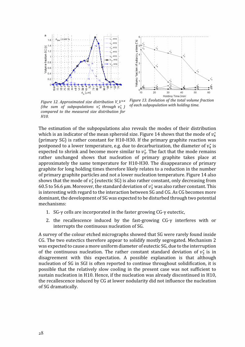
Figure12.ApproximatedsizedistributionV_V^*(the sum of subpopulations ∗ through ∗ )compared to themeasured size distribution forH10.
Figure13.Evolutionofthetotalvolumefractionofeachsubpopulationwithholdingtime.
The estimationof the subpopulations also reveals themodesof their distributionwhichisanindicatorofthemeanspheroidsize.Figure14showsthatthemodeof ∗(primarySG) isratherconstantforH10‐H30. If theprimarygraphitereactionwaspostponedtoalowertemperature,e.g.duetodecarburization,thediameterof ∗isexpectedtoshrinkandbecomemoresimilarto ∗.Thefactthatthemoderemainsrather unchanged shows that nucleation of primary graphite takes place atapproximately the same temperature forH10‐H30.Thedisappearanceofprimarygraphiteforlongholdingtimesthereforelikelyrelatestoareductioninthenumberofprimarygraphiteparticlesandnotalowernucleationtemperature.Figure14alsoshowsthatthemodeof ∗(eutecticSG)isalsoratherconstant,onlydecreasingfrom60.5to56.6µm.Moreover,thestandarddeviationof ∗wasalsoratherconstant.ThisisinterestingwithregardtotheinteractionbetweenSGandCG.AsCGbecomesmoredominant,thedevelopmentofSGwasexpectedtobedisturbedthroughtwopotentialmechanisms:
1. SG‐γcellsareincorporatedinthefastergrowingCG‐γeutectic,
2. the recallescence induced by the fast‐growing CG‐γ interferes with orinterruptsthecontinuousnucleationofSG.
AsurveyofthecolouretchedmicrographsshowedthatSGwererarelyfoundinsideCG.Thetwoeutecticsthereforeappeartosolidifymostlysegregated.Mechanism2wasexpectedtocauseamoreuniformdiameterofeutecticSG,duetotheinterruptionof the continuous nucleation. The rather constant standard deviation of ∗ is indisagreement with this expectation. A possible explanation is that althoughnucleationofSGinSGIisoftenreportedtocontinuethroughoutsolidification,it ispossible that the relatively slow cooling in the present casewas not sufficient tosustainnucleationinH10.Hence,ifthenucleationwasalreadydiscontinuedinH10,therecallescenceinducedbyCGatlowernodularitydidnotinfluencethenucleationofSGdramatically.
dA
[ m]
0
0.2
0.4
0.6
0.8
1
1.2
1.4
1.6
11
1 1 1 1 1 1 1 1 1 1 1 1 1 1 1 1 1 12 2 2 2 22 2
2 2 2 2 2 2 2 2 2 2 2 2 23 3 3 33
3
3
3
3 3
3
3
3
33
3 3 3 3 34 4 4 4 4 4 4 4 4 4
4
4
44
4
4
4 4 4 45 5 5 5 5 5 5 5 5 5 5 5 5 5 5 55
55 5
Eabs = 0.307 % v1* , H10
v2* , H10
v3* , H10
v4* , H10
v5* , H10
VV, H10
VV* , H10
a
10 20 30 40 50 60
Holding Time [min]
0
1
2
3
4
5
6
v1*
v1* v1
* v1* v1
* v1*
v2*
v2*
v2*
v2* v2
* v2*
v3*
v3*
v3*
v3*
v3*
v3*
v4*
v4*
v4*
v4*
v4* v4
*v5* v5
*
v5* v5
* v5* v5
*

On the Solidification of Compacted and Spheroidal Cast Irons
29
Figure14.Modeandstandarddeviationofsubpopulations.
The loss of contact of compacted graphite with the melt (Supplement II)
Results from Supplement II provides some further clues about the interactionbetweenSGandCGduringsolidification.TheelementalmapmeasuredusingEPMA‐WDS, allowed for study of the solidification history of the matrix. This isdemonstratedinFigure15,whichdisplaystheinferredmicrostructurewhen60%ofthematrixwassolid.Thechronologyofgraphiteisunknown,sographiteisdisplayedas it was found on the cross section. In Figure 15b most tips of CG are alreadyembedded in a thick layer of γ. For increasing holding times, the tips of CG areobservedclosertotheγfrontandeventuallypenetratesit.Thisshowsthatthetipsof CG lose contact with the melt at a progressively higher fraction solid as thenodularitydecreases.Graphitewhich is foundbeyond thisboundaryappear tobemostlyspheroidal.ItthereforefollowsthatthenodularityisnotonlydeterminedbythenumberofCG‐γandSG‐γatanearlystage,butalsobythedurationofwhichCGgrowsincontactwiththemelt.Thisappearsimportanttoconsiderinsolidificationmodels,asevenatasmallpercentnodularity,thelastpartofsolidification,maybepredominantlyofspheroidalcharacteristic.
0 10 20 30 40 50 60 70
Holding Time [min]
0
20
40
60
80
100
120
v1*
v1* v
1* v
1* v
1*
v1*
v2*
v2*
v2*
v2* v
2*
v2*
v3* v
3*
v3*
v3* v
3* v
3*
v4*
v4* v
4* v
4*
v4*
v4*
v5*
v5*
v5*
v5*
v5*
v5*

30
a
c
e
b
d
f
Figure 15. The solidification structurewhen 60% of thematrix had solidified, inferred from theelementalmapsmeasuredusingEPMA‐WDS.White:solidmatrix,grey:liquid,black:graphite.a:H10,b:H20,c:H30,d:H40,e:H50,f:H60.

On the Solidification of Compacted and Spheroidal Cast Irons
31
MICROSEGREGATION IN SGI AND CGI (SUPPLEMENT II)
It isobvious fromtheelementalmaps inFigure16andFigure17that thegrowthmodeoftheeutecticinfluencesthespatialsegregationpatterns.ThelargerCG‐γcellsproducelargerareasrichinSiandCuandimpoverishedofMn,PandSn.ThesmallerSG‐γcellsproducemicrosegregationonafinerscale,simplyduetotheirsmallersize.TheliteratureprovidescluesthattheratherstrangegrowthmechanismoftheSG‐γeutecticmayinfluencemicrosegregationonamorefundamentallevel.ThisrequiresfurtheranalysisoftheEPMA‐WDSdata.
a b
Figure16.ElementalmapofSiforalloyAmeasuredusingEPMA‐WDS.a:H10,b:H60.
a
b
Figure17.ElementalmapofMnforalloyAmeasuredusingEPMA‐WDS.a:H10,b:H60.
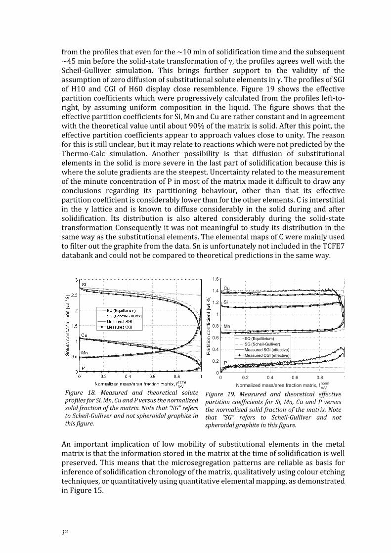
SoluteprofilesconstructedfromthesamedataareshowninFigure18.ThedashedlineisthetheoreticalconcentrationinγcalculatedforthealloyusingThermo‐CalcandtheTCFE7databank.Assumingzerodiffusionoftheelementsinthesolidγ,theprofilesareexpectedtofollowtheScheil‐Gullivercurves.Back‐diffusionisexpectedtocausetheprofiletohomogenizeandfallbacktowardstheequilibrium.Itisclear
32
fromtheprofilesthatevenforthe~10minofsolidificationtimeandthesubsequent~45minbeforethesolid‐statetransformationofγ,theprofilesagreeswellwiththeScheil‐Gulliver simulation. This brings further support to the validity of theassumptionofzerodiffusionofsubstitutionalsoluteelementsinγ.TheprofilesofSGIof H10 and CGI of H60 display close resemblence. Figure 19 shows the effectivepartitioncoefficientswhichwereprogressivelycalculatedfromtheprofilesleft‐to‐right, by assuming uniform composition in the liquid. The figure shows that theeffectivepartitioncoefficientsforSi,MnandCuareratherconstantandinagreementwiththetheoreticalvalueuntilabout90%ofthematrixissolid.Afterthispoint,theeffectivepartitioncoefficientsappeartoapproachvaluesclosetounity.Thereasonforthisisstillunclear,butitmayrelatetoreactionswhichwerenotpredictedbytheThermo‐Calc simulation. Another possibility is that diffusion of substitutionalelementsinthesolidismoresevereinthelastpartofsolidificationbecausethisiswherethesolutegradientsarethesteepest.UncertaintyrelatedtothemeasurementoftheminuteconcentrationofPinmostofthematrixmadeitdifficulttodrawanyconclusions regarding its partitioning behaviour, other than that its effectivepartitioncoefficientisconsiderablylowerthanfortheotherelements.Cisinterstitialin the γ lattice and is known todiffuse considerably in the solidduring and aftersolidification. Its distribution is also altered considerably during the solid‐statetransformationConsequentlyitwasnotmeaningfultostudyitsdistributioninthesamewayasthesubstitutionalelements.TheelementalmapsofCweremainlyusedtofilteroutthegraphitefromthedata.SnisunfortunatelynotincludedintheTCFE7databankandcouldnotbecomparedtotheoreticalpredictionsinthesameway.
Figure 18. Measured and theoretical soluteprofilesforSi,Mn,CuandPversusthenormalizedsolidfractionofthematrix.Notethat“SG”referstoScheil‐Gulliverandnotspheroidalgraphiteinthisfigure.
Figure 19. Measured and theoretical effectivepartitioncoefficients forSi,Mn,CuandPversusthenormalizedsolid fractionofthematrix.Notethat “SG” refers to Scheil‐Gulliver and notspheroidalgraphiteinthisfigure.
An important implication of lowmobility of substitutional elements in themetalmatrixisthattheinformationstoredinthematrixatthetimeofsolidificationiswellpreserved.Thismeans that themicrosegregationpatternsarereliableasbasis forinferenceofsolidificationchronologyofthematrix,qualitativelyusingcolouretchingtechniques,orquantitativelyusingquantitativeelementalmapping,asdemonstratedinFigure15.
0 0.2 0.4 0.6 0.8 1
Normalized mass/area fraction matrix, fA/Vnorm
0
0.2
0.4
0.6
0.8
1
1.2
1.4
1.6
Si
Cu
Mn
P
EQ (Equilibrium)SG (Scheil-Gulliver)Measured SGI (effective)
Measured CGI (effective)

On the Solidification of Compacted and Spheroidal Cast Irons
33
QUANTIFICATION THE DENDRITIC AUSTENITE (SUPPLEMENT III) Properties of the technique for revealing the
dendritic austenite structure
TheheattreatmentandwaterquenchingappliedtothehypoeutecticalloyAresultedincoherentγdendritesofvariouscoarsenessembeddedinamatrixofpredominantlyledeburite. A technique for producing a contrast between the dendritic γ and theledeburitewasdeveloped.TheeffectofthetechniquecanbeviewedinFigure20a,ascapturedusingopticalmicroscopy.Figure20bshowsthatthecolouringoccursinthenon‐cementiteregionsoftheledeburiteanddisplaysaspectrumofcolours.ThemoreuniformcolouringoftheledeburiteobservedatlowermagnificationinFigure20aistherefore an average effect. Figure 20b also shows the rather rugged boundarybetween the dendritic structure and the ledeburite matrix, making it difficult todetermine the original melt‐dendrite boundary. In some cases, the matrix alsocontainedsmallgraphite‐γeutecticcellsandamuchfinerpopulationofdendrites,bothofwhichwerejudgedtohaveformedduringthequenchingprocedure.Theseoftenhadsimilarcolourtothedendriticstructure intendedformeasurement,andthereforeproblematic.Arapidquenchingprocedurewas thereforeemphasizedascrucialtomeasurethedendriticγasitwouldrefinetheledeburiteandreducethelikelihood formation of graphite‐γ eutectic. An undesired effect of the colouringtechnique was however the sporadic darkening of the martensite needles in thedendritestructure,whichreducedthecontrasttotheledeburitematrix.Thiswillnotimprovebyacceleratingthecoolingduringquenching,butisdirectlyrelatedtothecolouringtechnique.Themechanismforthedarkeningofthemartensiteandhowtoprevent itwasnot found.Yet, thecolouringtechniquewas foundadvantageous inthatthecolouringofthedendriticstructurewasratheruniformandconsistent,andprovidedanadequatecontrasttotheledeburitematrix.Thesepropertiesfacilitatecomputeraidedimageanalysis.
a
b
Figure20.Micrographsdemonstratingthecolouringoftheledeburiteforthealloyquenchedduringsolidification,withouttheapplicationofisothermalheattreatment.

34
Measuring the volume fraction and surface area per unit volume of the dendritic structure
Thevolumefraction andsurfaceareaperunitvolume ofthedendriticstructurewasofparticularinteresttomeasuresincetheircombinationhasbeenshowntobeofimportancetothetensilepropertiesofLGI[90,91],andproposedtobeimportanttointerdendriticfeedingintheformofthehydraulicdiameteroftheinterdendriticspace [27, 91]. The parameters were measured on the cross sections usingstereologicalrelations,undertheassumptionofuniformdistributionofthedendriticstructure in the specimens. Despite the advantageous effects of the colouringtechnique,itwasnotpossibletoadequatelyisolatethedendriticstructureintendedfor measurement by direct application of a commercial image analysis software.Instead,aschemeinvolvingselectiontoolsofacommercialrastergraphicseditorwasapplied to produce binary images from the micrographs, where the dendriticstructurewas represented in black against awhite background. Automatic imageanalysiswasthenappliedtothebinaryimageswithtomeasure and .However,someobviousresidualdisagreementwasfoundbetweenmicrographsandthebinaryimages.Toassesstheimpactoftheseonthemeasurementofthetwoparameters,thebinaryimagesweremanuallycleanedup,afterwhichtheparametersweremeasuredagain. Measurements on the corrected binary images are denoted by asterix.Moreover,thetwoparameterswerealsomeasuredusingmanualpointfractionandlineintercepttechniques.Thesystematicerrorofthesemethodsisconsideredsmall,asasimplejudgementismadeforeachpointorlineintercept.Themeasuredvaluesare summarized in Figure 21 and Figure 22. A, B, C and D represent dendritecoarsenessof the investigatedmaterial from finest to coarsest.Thesuffixnumber(A1,A2,etc.)designatesthequadrantofthecrosssectiononwhichthemeasurementwasmade.
Figure21.Themeasuredvolumefractiondendriticaustenite. and ∗weremeasuredontheuncorrectedandcorrectedbinaryimagesrespectivelyusingautomaticimageanalysis. isthe
measuredpointfractionmeasuredontherawmicrographs.

On the Solidification of Compacted and Spheroidal Cast Irons
35
Figure22.Themeasuredsurfaceareaperunitvolumeofthedendriticaustenite. and ∗were
measuredontheuncorrectedandcorrectedbinaryimagesrespectivelyusingautomaticimageanalysis.wasmeasuredusingalineintercepttechniqueontherawmicrographs.
The agreement between the measurements on the binary images and the pointcounting and line intercept techniques was analysed. The results of the analysisindicatedthatthemanualcorrectionsofthebinaryimagescausedonlyasmallchangeinthemeasuredvaluescomparedtothedisagreementwiththepointcountingandline intercept techniques.The identifieddiscrepanciesbetween thebinary imagesandtherawmicrographsthereforeaccountedforonlyaminorerrorinthemeasuredvalues.
For ,thesystematicdisagreementwiththepointfractionwasthelargestforthefinest dendritic structurebut insignificant for the coarser structures.The randomdisagreementwashoweverlargerforthecoarserstructures.Thepriorwasproposedtorelatetothelargeperimeterofthefinestructure,makingevenasmalloffsetintheestimatedboundaryofthedendriticγresult ina largedifference inthemeasuredarea. The latter likely relates to the increasing scale of the measured structurerelativetothesampledarea.
Thesystematicdisagreementof withthevaluesmeasuredusingthelineintercepttechnique was on the contrary largest for the coarsest structure. The randomdisagreementwas,as for , largest for thecoarseststructure,presumably for thesamereason.The largesystematicdisagreementof for thecoarseststructure isproposed to relate to the ill defined boundary of the dendritic γ structure. Theemployedselectionschemeresultedinaratherirregularboundarywhichwasnotrepresentativeof the relatively roundedshapeof thecoarsestdendritic structure,resultinginanoverestimationof .

36
On the Solidification of Compacted and Spheroidal Cast Irons
37
CHAPTER 4
CONCLUSIONS
Inthischapter,someoftheconclusionshavebeendrawn.
Interactionsbetweenspheroidalandcompactedeutectic
Fordecreasingnodularity, theCGloses itscontactwiththemeltataneverhighersolidfraction,afterwhichsolidificationisdominatedbySG.ThemodeandwidthofthesizedistributionofeutecticSGwasroughlyindependentofnodularity.Thetwomorphologies developed rather segregated, and the recallescence induced byincreasing fraction of CG did not interfere noticeably with the nucleation of SG.Primary SG was identified for high nodularity, but gradually disappeared fordecreasingnodularity,leavingeutecticSGdominant.Thismayhoweverhavebeenanartefactoftheexperimentalmethod,andnotaconsequenceofthenodularity.
MicrosegregationinSGIandCGI
TheevolutionoftheconcentrationofSi,Cu,andMninthemeltagreedwellwiththetheoreticalpredictionscalculatedusingtheGulliver‐ScheilsolidificationmoduleofThermo‐CalcandtheTCFE7databank,independentofnodularity.Thenodularitythereforeappearstohavenoinfluenceonthemagnitudeofmicrosegregation,onlyonitsspatialpatterns.Theresultsarealsoinstrongsupportofthediffusionofsubstitutionalelementsinthesolidbeingnegligiblysmallincastirons,evenforasolidificationtimeof10min.
Quantificationofdendriticaustenite
Thedevelopedetchingmethodwasfoundtocolourthenon‐cementiteregionsofledeburite,givingrisetoanaveragecolouringeffectoftheledeburitematrixatlowmagnifications,incontrasttothepaledendriticγstructure.Aschemeforproducingbinaryimagesfromthemicrographs,moreappropriateforautomaticimageanalysisofthestructure,waspresentedanddemonstrated.Mostsystematicdisagreementwiththelinepointfractionandlineintercepttechniquesappearstorelatetothedifficultyofdefiningtheboundarybetweenthedendriticstructureandtheledeburitematrix.Thiseffectproducedthelargestsystematicdisagreementforthefinestmicrostructurewhenmeasuringthevolumefraction,andlargestsystematicdisagreementforthecoarseststructurewhenmeasuringthesurfaceareaperunitvolume.

38

On the Solidification of Compacted and Spheroidal Cast Irons
39
CHAPTER 5
FUTURE WORK
CHAPTER INTRODUCTION
Inthischapter,plansforthedirectionoffutureworkarepresented.
Thedevelopedmethodtodeterminethesolidificationsequenceofthematrixusingelemental mapping will be employed to investigate the chronology of shrinkageporositiesinexperimentalandindustrialcastings.
Furthermore, future work will focus on the influence of the cooling rate on thesolidification of a slightly hypoeutectic CGI. Solidification will be studied usingthermal analysis, interrupted solidification experiments, and a heat treatmenttechniquewhichallowsforretentionofausteniteatroomtemperature.
ThesamebasicexperimentaltechniquewillbeemployedasinSupplementIandIIinthepresentwork,howevertheholdingtimewillbeconstanttoproducelowvariationinnodularity.Instead,thecoolingratewillbevaried,byprogrammingacontrolledramp‐downofthefurnacetemperature.Earlyexperimentswillfocusontemperaturerecording for thermal analysis. The development of the microstructure will befollowed by quenching the material in water at different times of solidification.Moreover,thegrainstructurewillbestudiedusingaheattreatmenttechniquecalleddirectaustemperingaftersolidificationwhichallowsforpartialretentionofγdowntoroomtemperature.

40

On the Solidification of Compacted and Spheroidal Cast Irons
41
REFERENCES
1. Staff, A.M.C., 49th Census of World Casting Production. Modern Casting, 2015. 12: p. 26-31.
2. Compacted Graphite Iron Castings, in ASM Handbook. 2008, ASM International. p. 872-883.
3. Dawson, S., Compacted Graphite Iron - A material solution for modern diesel engine solution for modern diesel engine blocks and heads. China Foundry, 2009(August): p. 241-246.
4. Goodrich, G.M., Introduction to Cast Irons, in ASM Handbook. 2008, ASM International. p. 785-811.
5. Kagawa, A. and T. Okamoto, Coefficients for equilibrium partition of a third element between solid and liquid in iron-carbon base ternary alloys and their relation to graphitization during iron-carbon eutectic solidification. Journal of Materials Science, 1984. 19(7): p. 2307-2318.
6. Kurz, W. and D.J. Fisher, Fundamentals of solidification. 1986: Trans Tech Publications. 7. Bramfitt, B., The effect of Carbide and Nitride Additions on the Heterogeneous Nucleation
Behavior of Liquid Iron. Metallurgical Transactions, 1970. 1(7): p. 1987-1995. 8. Oldfield, W., A quantitative approach to casting solidification: freezing of cast iron. 1966. 9. Skaland, T., Ø. Grong, and T. Grong, A Model for the Graphite Formation in Ductile Cast
Iron: Part I. Inoculation Mechanisms. Metallurgical Transactions A, 1993. 24(10): p. 2347-2353.
10. Mizoguchi, T. and J.H. Perepzko, Nucleation behavior during solidification of cast iron at high undercooling. Materials Science and Engineering: A, 1997. 226: p. 813-817.
11. Miyake, H. and A. Okada, Nucleation and Growth of Primary Austenite in Hypoeutectic Cast Iron. AFS Transactions, 1998: p. 581-587.
12. Kayama, N., K. Nashimoto, and K. Suzuki, Effect of SiO2 on Primary Austenite Nucleation in Hypoeutectic Cast Iron. 1984: Castings Research Laboratory, Waseda University. p. 15-24.
13. Diószegi, A., K.Z. Liu, and I.L. Svensson, Inoculation of primary austenite in grey cast iron. International Journal of Cast Metals Research, 2007. 20(2): p. 68-72.
14. Feest, E., Inoculation of grey cast iron. Solidification Technology in the Foundry and Cast House, 1980: p. 232-239.
15. Wang, C. and H. Fredriksson. On the Mechanism of Inoculation of Cast Iron Melts. in 48th International Foundry Congress, Varna, Bulgaria. 1981.
16. Edalati, K., F. Akhlaghi, and M. Nili-Ahmadabadi, Influence of SiC and FeSi addition on the characteristics of gray cast iron melts poured at different temperatures. Journal of Materials Processing Technology, 2005. 160(2): p. 183-187.
17. Wallace, J.F., Effects of Minor Elements on the Structure of Cast Irons. Transactions of the American Foundrymen's Society., 1975. 83: p. 363-378.
18. Sommerfeld, A., B. Bottger, and B. Tonn, Graphite nucleation in cast iron melts based on solidification experiments and microstructure simulation. Journal of Materials Science and Technology, 2008. 24(3): p. 321-324.
19. Warrick, R., Spheroidal graphite nuclei in rare earth and magnesium inoculated irons. Cast Metals Research Journal, 1966. 2(3): p. 97-108.
20. Lux, B., Nucleation of Eutectic Graphite in Inoculated Gray Iron by Saltlike Carbides. Modern Casting, 1964. 54: p. 41-47.
21. Okamoto, T., X. Huang, and A. Kagawa, Graphite nodularization and graphitization of magnesium treated cast irons solidified under argon atmosphere pressure up to 145 atm. Metal Science, 1984. 18: p. 169-176.
22. Oldfield, W., Solidification of Hypo-eutectic Cast Iron. 1961: University of Manchester.

42
23. Dantzig, J.A. and M. Rappaz, Solidification. First Edition ed. Materials, ed. M. Rappaz. 2009, 6000 Broken Sound Parkway, NW, Suite 300, Boca Raton, FL 33487: CRC Press. 621.
24. Wu, X.-m., et al., Model of Primary Austenite Dendrite Structure in Hypoeutectic Cast Iron. Journal of Iron and Steel Research International, 2003. 10(1): p. 33-35.
25. Mampaey, F. and Z.A. Xu, Grain impingement during solidification of cast iron. Cast Metals, 1994. 7(3): p. 165-174.
26. Elmquist, L., S. Salera, and A. Diószegi, Inoculation and its effect on primary solidification structure of hypoeutectic grey cast iron. International Journal of Cast Metals Research, 2010. 23(2): p. 124-129.
27. Lora, R. and A. Diószegi, Dynamic Coarsening of 3.3C–1.9Si Gray Cast Iron. Metallurgical and Materials Transactions A, 2012. 43(13): p. 5165-5172.
28. Ruff, G. and J. Wallace, Control of graphite structure and its effect on mechanical properties of gray iron. AFS Trans, 1976. 84: p. 705-728.
29. Marsh, S.P. and M.E. Glicksman, Overview of Geometric Effects on Coarsening of Mushy Zones. Metallurgical and Materials Transactions A, 1996. 27A(3): p. 557-567.
30. Hernando, J.C. and A. Diószegi, An Overview of Isothermal Coarsening in Hypoeutectic Lamellar Cast Iron, in Advances in the Science and Engineering of Casting Solidification: An MPMD Symposium Honoring Doru Michael Stefanescu, L. Nastac, et al., Editors. 2016, Springer International Publishing: Cham. p. 295-302.
31. Keverian, J. and H.F. Taylor, Effects of gaseous and solid addition elements on surface tension and contact angle (on graphite) of various iron-carbon alloys. Transactions of the American Foundrymen's Society., 1957. 65(s 212).
32. Sadocha, J. and J. Gruzleski. The Mechanism of Graphite Spheroid Formation in Pure Fe-C-Si Alloys. in Proceedings of the 2nd International Symposium on The Metallurgy of Cast Iron. 1976.
33. Keverian, J., H.F. Taylor, and J. Wulff, Experiments on spherulite formation in cast iron. American Foundryman, 1953. 23(6): p. 85-91.
34. McSwain, R., C. Bates, and W. Scott, Iron-graphite surface phenomena and their effects on iron solidification. Transactions of the American Foundrymen's Society, 1974. 82: p. 85-94.
35. Takita, M. and Y. Ueda, Influence of Interfacial Energy on the Shape of Graphite in Cast Iron. Transactions of the Japan Institute of Metals, 1979. 20: p. 569-576.
36. Subramanian, S. and D. Kay, Compacted Graphite Morphology Control.(Retroactive Coverage). American Foundrymen's Society, Inc, 1982: p. 589-603.
37. Tiller, W., et al., The redistribution of solute atoms during the solidification of metals. Acta metallurgica, 1953. 1(4): p. 428-437.
38. Double, D. and A. Hellawell, The nucleation and growth of graphite—The modification of cast iron. Acta metallurgica et materialia, 1995. 43(6): p. 2435-2442.
39. Double, D. and A.H. Well, Defects in eutectic flake graphite. Acta Metallurgica, 1971. 19(12): p. 1303-1306.
40. Hillert, M. and Y. Lindblom, The growth of nodular graphite. Journal of the iron and steel institute, 1954. 176(4): p. 388-&.
41. Qijie, Z. and H. Hanqi, Effect of Nitrogen on Graphite Morphology in Gray Cast Iron. Acta Metallurgica Sinica, 1992. 28(10): p. 73-78.
42. Pedersen, K.M. and N. Tiedje, Solidification of Hypereutectic Thin Wall Ductile Cast Iron. Materials Science Forum, 2006. 508: p. 63-68.
43. Olen, K.R. and R.W. Heine, A Revision of the Fe-C-Si System. Cast Metals Research Journal, 1968. 4(1): p. 28-43.
44. Heine, R.W. and C.R. Loper, On Dendrites and Eutectic Cells in Gray Iron. AFS Transactions, 1969. 77: p. 185-191.
On the Solidification of Compacted and Spheroidal Cast Irons
43
45. Qing, J., V.L. Richards, and D.C. Van Aken, Examination of Spheroidal Graphite Growth and Austenite Solidification in Ductile Iron. Metallurgical and Materials Transactions A, 2016. 47(12): p. 6197-6213.
46. Lakeland, K. and L. Hogan, The Coupled Zone Concept Applied to Solidification of Cast Irons. 1968.
47. Fredriksson, H., The Coupled Zone in Grey Cast Iron. Metallurgical Transactions A, 1975. 6A: p. 1658-1660.
48. Zhu, M., et al., Modeling of microstructural evolution during divorced eutectic solidification of spheroidal graphite irons. Acta Materialia, 2015. 84: p. 413-425.
49. Schöbel, J.-D. Precipitation of Graphite during the Solidification of Nodular Cast Iron. 1964. Detroit, Michigan: Gordon and Breach Science Publishers Inc.
50. Fredriksson, H., J. Stjerndahl, and J. Tinoco, On the solidification of nodular cast iron and its relation to the expansion and contraction. Materials Science and Engineering a-Structural Materials Properties Microstructure and Processing, 2005. 413: p. 363-372.
51. Sikora, J.A., R.E. Boeri, and G.L. Rivera, Solidification of Gray Cast Iron. Scripta Materiala, 2004. 50: p. 331-335.
52. Rivera, G.L., et al., Examination of the solidification macrostructure of spheroidal and flake graphite cast irons using DAAS and EBSD. Materials Characterization, 2008. 59: p. 1342-1348.
53. Hultgren, A., Y. Lindblom, and E. Rudberg, Eutectic Solidification in Grey, White, and Mottled Hypo-Eutectic Cast Irons. Journal of the Iron and Steel Institute, 1954. 176: p. 365-374.
54. Fredriksson, H. and S.-E. Wetterfall, A Study of Transition from Undercooled to Flake Graphite in Cast Iron, in The Metallurgy of Cast Iron. 1975, Georgi Publishing: Geneva, Switzerland. p. 277-293.
55. Morrogh, H., Graphite Formation in Grey Cast Irons and Related Alloys. B.C.I.R.A. Journal of Research and Development, 1955. 5: p. 655-673.
56. Diószegi, A., Evaluation of eutectic growth in grey cast iron by means of inverse modelling. International Journal of Cast Metals Research, 2003. 16(1-3): p. 301-306.
57. Muhmond, H.M. and H. Fredriksson, Relationship Between the Trace Elements and Graphite Growth Morphologies in Cast Iron. Metallurgical and Materials Transactions A, 2014: p. 1-13.
58. Wetterfall, S.-E., H. Fredriksson, and M. Hillert, Solidification process of nodular cast iron. Journal of the Iron and Steel Institute, 1972. 210(5): p. 323-333.
59. Tinoco, J., et al., Thermal analysis of nodular and lamellar eutectic cast iron under different cooling rates. International Journal of Cast Metals Research, 2003. 16(1-3): p. 53-58.
60. Mampaey, F., Influence of Compacted Graphite on Solidification Morphology of Cast Iron. AFS Transactions, 2000. 27: p. 11-17.
61. Stefanescu, D., F. Martinez, and I. Chen, Solidification behavior of hypoeutectic and eutectic compacted graphite cast irons, chilling tendency and eutectic cells. AFS transactions, 1983. 91: p. 205-216.
62. Chen, J., et al., Liquid metal channel formation in compacted/vermicular graphite cast iron solidification. Transactions of the American Foundrymen's Society., 1986. 94: p. 537-544.
63. Geier, G.F., et al., Microstructure transition from lamellar to compacted graphite using different modification agents. Materials Science and Engineering: A, 2005. 413–414(0): p. 339-345.
64. Dhindaw, B. and J.D. Verhoeven, Nodular graphite formation in vacuum melted high purity Fe-C-Si alloys. Metallurgical Transactions A, 1980. 11(6): p. 1049-1057.
65. Lekakh, S., et al., Graphite Nodule Size Distribution in Ductile Iron. AFS Proceedings, 2013.

44
66. Vazehrad, S., J. Elfsberg, and A. Diószegi, Study of microstructure and silicon segregation in cast iron using colour etching and electron microprobe analysis. Materials Characterization, 2015. 104: p. 132-138.
67. Vazehrad, S., A Study on Factors Influencing the Microstructure and Shrinkage Porosity Formation in Compacted Graphite Iron, in Department of Materials Science and Engineering. 2014, KTH Royal Institute of Technology. p. 51.
68. Pedersen, K.M. and N.S. Tiedje, Graphite nodule count and size distribution in thin-walled ductile cast iron. Materials Characterization, 2008. 59(8): p. 1111-1121.
69. König, M., Microstructure Formation During Solidification and Solid State Transformation in Compacted Graphite Iron, in Department of Mechanical Engineering (Jönköping University), Department of Materials and Manufacturing Technology (Chalmers University). 2011, Jönköping University School of Engineering, Chalmers University of Technology: DiVA.
70. Mampaey, F., Modelling Nucleation in Lamellar and Spheroidal Graphite Cast Iron, in 58th World Foundry Congress. 1991: Krakow. p. 3-38.
71. Fraz, E., et al., Numerical Simulation and FTA of Solidificaiton Kinetics in High-Carbon Fe-C Alloys. Metallurgical and Materials Transactions B, 1997. 28(1): p. 115-123.
72. Dugic, I. and I.L. Svensson, An Investigation of the Effect of Inoculants on the Metal Expansion Penetration in Grey Iron. International Journal of Cast Metals Research, 1999. 11(5): p. 333-338.
73. Svensson, I.L., A. Millberg, and A. Diószegi, A Study of Eutectic Inoculation in Grey Cast Iron by Addition of Fe-Si-Ca-Al-, Zr, Ba, Ti, RE and C. International Journal of Cast Metals Research, 2003. 16: p. 29-34.
74. Fredriksson, H. and U. Akerlind, Solidification and crystallization processing in metals and alloys. 2012: John Wiley & Sons.
75. Clyne, T. and W. Kurz, Solute redistribution during solidification with rapid solid state diffusion. Metallurgical and Materials Transactions A, 1981. 12(6): p. 965-971.
76. Stefanescu, D.M., Science and engineering of casting solidification. Third Edition ed. 2015: Springer.
77. Gulliver, G., The quantitative effect of rapid cooling upon the constitution of binary alloys. J. Inst. Met, 1913. 9(1): p. 120-157.
78. Scheil, E., Bemerkungen zur schichtkristallbildung. Zeitschrift für Metallkunde, 1942. 34(3): p. 70-72.
79. Kraft, T. and Y.A. Chang, Predicting microstructure and microsegregation in multicomponent alloys. JOM, 1997. 47: p. 20-28.
80. Burton, J., R. Prim, and W. Slichter, The distribution of solute in crystals grown from the melt. Part I. Theoretical. The journal of chemical physics, 1953. 21(11): p. 1987-1991.
81. Aziz, M.J., An Atomistic Model of Solute Trapping, in Rapid solidification processing: Principles and Technologies III : Proceedings of the Third Conference on Rapid Solidification Processing. 1982: National Bureau of Standards, Gaithersburg, Maryland. p. 113-117.
82. Morita, Z.-i. and T. Tanaka, Thermodynamics of solute distributions between solid and liquid. Transactions of the Iron and Steel Institute of Japan, 1983. 23(10): p. 824-833.
83. Motz, J.M., Microsegregation an easily unnoticed influencing variable in the structural desciption of cast materials. Practical Metallography, 1988. 25: p. 285-293.
84. Boeri, R. and F. Weinberg. Microsegregation in ductile iron. in 93 rd AFS Casting Congress. 1989.
85. Boeri, R. and F. Weinberg, Microsegregation of Alloying Elements in Cast Iron. Cast Metals, 1993. 6(3): p. 153-158.
86. (ISO), I.O.f.S., ISO 16112:2006(E) - Compacted (vermicular) graphite cast irons - Classification. 2006: Switzerland.
On the Solidification of Compacted and Spheroidal Cast Irons
45
87. Basak, C. and A.K. Sengupta, Development of a FDM based code to determine the 3-D size distribution of homogeneously dispersed spherical second phase from microstructure: a case study on nodular cast iron. Scripta Materialia, 2004. 51(3): p. 255-260.
88. Underwood, E.E., Quantitative Stereology. Metallurgy and Materials. 1970, Reading, Massachusetts: Addison-Wesley Publishing Company. 274.
89. Pedersen, K.M. and N. Tiedje, Nucleation and solidification of thin walled ductile iron—Experiments and numerical simulation. Materials Science and Engineering: A, 2005. 413-414: p. 358-362.
90. Fourlakidis, V. and A. Diószegi, A generic model to predict the ultimate tensile strength in pearlitic lamellar graphite iron. Materials Science and Engineering: A, 2014. 618: p. 161-167.
91. Diószegi, A., V. Fourlakidis, and I.L. Svensson, Microstructure and tensile properties of grey cast iron. 2004, School of Engineering, Jönköping University: Jönköping.

46

On the Solidification of Compacted and Spheroidal Cast Irons
47
APPENDED PAPERS
SupplementI B. Domeij, J.C. Hernando, A. Diószegi, Size distribution ofGraphite Nodules in Hypereutectic Cast irons of varyingNodularity,Manuscript
SupplementII B. Domeij, A. Diószegi, Inferring the development ofmicrosegregation and microstructure in Spheroidal andCompactedGraphiteIronusingEPMA‐WDS,Manuscript
SupplementIII Domeij,B.,J.C.Hernando,andA.Diószegi,QuantificationofDendriticAusteniteAfterInterruptedSolidificationinaHypoeutecticLamellarGraphiteIron.Metallography,Microstructure,andAnalysis,2016.5(1):p.28‐42.

48