On the origin of the optical vortex lattices in a …users.uoa.gr/~smpanos/ergasia14.pdfOn the...
4
On the origin of the optical vortex lattices in a nematic liquid crystal light valve ENRIQUE CALISTO, 1,2 MARCEL G. CLERC, 2, * MICHAL KOWALCZYK, 1 AND PANAYOTIS SMYRNELIS 3 1 Departamento de F ı ´sica and Millennium Institute for Research in Optics, Facultad de Ciencias F ı ´sicas y Matemáticas, Universidad de Chile, Casilla 487-3, Santiago, Chile 2 Departamento de Ingenier ı ´a Matemática and CMM, Universidad de Chile, Casilla 170 Correo 3, Santiago, Chile 3 Institute of Mathematics, Polish Academy of Sciences, 00-656 Warsaw, Poland *Corresponding author: [email protected] Received 29 January 2019; revised 7 May 2019; accepted 9 May 2019; posted 13 May 2019 (Doc. ID 359005); published 3 June 2019 Optical vortices and lattices of these are attracting the attention of the scientific community because of their applications in various fields of optical processing, commu- nications, enhanced imaging systems, and bio-inspired devices. Programmable optical vortices lattices with arbi- trary distributions have been achieved using illuminated liquid crystals with photosensitive walls. Using an ampli- tude equation that describes these optical valves close to the Freédericksz transition allows us to characterize analytically the vortices and the lattices they form. The numerical simulations of the amplitude equation, analyt- ical solutions, and experimental observations show good agreement. © 2019 Optical Society of America https://doi.org/10.1364/OL.44.002947 Optical vortices are point phase dislocations; that is, they are singular points where the electromagnetic field goes to zero and around which the phase distribution forms an N -armed spiral, with N being the topological charge [1–3]. In the last decade, optical vortices have attracted attention for their diverse pho- tonic applications [4], ranging from the interchange of angular momentum between light and matter [5], optical tweezers [6–8], quantum computation [9], enhancement of astronomi- cal images [10], the generation of optical beams by micro/nano patterned in liquid crystals [11–16], and data transmission [17]. In all these applications, optical vortex lattices are always involved and required, because they contain multiple optical vortices that supply information, flexibility, and manipulation [17–19]. Indeed, the generation, detection, and manipulation of optical vortex lattices are of fundamental relevance in the research described and in future optical applications. The reali- zation of programable lattices of optical vortices with arbitrary distribution in space was demonstrated by exploiting reorienta- tional nonlinearities in the nematic liquid crystal layer of a light valve [20]. The vortex arrangements were determined qualita- tively on the basis of consistent topological rules governing light-induced matter defects of both signs. When a liquid crys- tal light valve is illuminated by a Gaussian beam, a vortex in the molecular orientation (umbilic defect) is induced [21,22]. The umbilical defects are topological charges 1. In this Letter, we establish analytically the origin of the vor- tex lattices observed in illuminated liquid crystal layers with photosensitive walls. Using a topologically driven Ginzburg– Landau equation that describes illuminated liquid crystal light valves close to the Fréedericksz transition, we model the vortices and the lattices they form. Figure 1 shows typical experimental, numerical, and analytical vortex lattices of an illuminated liquid crystal light valve. The numerical simula- tions of the amplitude equation, analytical solutions, and experimental observations show good agreement. The liquid crystal light valve is composed of a thin nematic liquid crystal film sandwiched between a glass and a photocon- ductive plate. The liquid crystal light valve is filled with a nem- atic mixture exhibiting negative dielectric anisotropy. The transparent interfaces are treated in order to provide a homeo- tropic alignment of the liquid crystals, that is, close to the walls, the liquid crystal molecules are perpendicular to the confining layers, one of which is the photoconductive slab. The director ~ nz , x , y, t accounts for the orientational organization of the molecules, where z and fx , yg, respectively, are the longitudinal and transverse coordinates. Owing to the photoconductive sub- strate and transparent electrodes, when the liquid crystal light valve is illuminated, the effective voltages V z , x , y drop across the liquid crystal layer which acquires a profile proportional to the light intensity I x , y on the liquid crystal layer, V z , x , y z ∕d V 0 αI x , y [21]. Where V 0 is the voltage applied to the liquid crystal light valve, d and α are the thick- ness of the valve and the phenomenological dimensional parameter, respectively, that describe the linear response of the photoconductor. The elongated molecules of the liquid crystal start to reor- ient as a result of the torque exerted by the induced electric field and tend to align perpendicularly to it. The homeotropic state, ~ n ˆ z , undergoes an stationary instability for a critical voltage. Indeed, this molecular reorientation instability corresponds to the Fréedericksz transition [23]. Close to this transition, one can use the following ansatz for the amplitude of the critical spatial mode ~ n ≈ ux , y, t sinπz ∕d , vx , y, t sinπz ∕d , 1 - u 2 v 2 sin 2 πz ∕d ∕2. Substituting it in the director Letter Vol. 44, No. 12 / 15 June 2019 / Optics Letters 2947 0146-9592/19/122947-04 Journal © 2019 Optical Society of America
Transcript of On the origin of the optical vortex lattices in a …users.uoa.gr/~smpanos/ergasia14.pdfOn the...
On the origin of the optical vortex lattices in anematic liquid crystal light valveENRIQUE CALISTO,1,2 MARCEL G. CLERC,2,* MICHAŁ KOWALCZYK,1 AND PANAYOTIS SMYRNELIS3
1Departamento de Fısica and Millennium Institute for Research in Optics, Facultad de Ciencias Fısicas y Matemáticas, Universidad de Chile,Casilla 487-3, Santiago, Chile2Departamento de Ingenierıa Matemática and CMM, Universidad de Chile, Casilla 170 Correo 3, Santiago, Chile3Institute of Mathematics, Polish Academy of Sciences, 00-656 Warsaw, Poland*Corresponding author: [email protected]
Received 29 January 2019; revised 7 May 2019; accepted 9 May 2019; posted 13 May 2019 (Doc. ID 359005); published 3 June 2019
Optical vortices and lattices of these are attracting theattention of the scientific community because of theirapplications in various fields of optical processing, commu-nications, enhanced imaging systems, and bio-inspireddevices. Programmable optical vortices lattices with arbi-trary distributions have been achieved using illuminatedliquid crystals with photosensitive walls. Using an ampli-tude equation that describes these optical valves closeto the Freédericksz transition allows us to characterizeanalytically the vortices and the lattices they form. Thenumerical simulations of the amplitude equation, analyt-ical solutions, and experimental observations show goodagreement. © 2019 Optical Society of America
https://doi.org/10.1364/OL.44.002947
Optical vortices are point phase dislocations; that is, they aresingular points where the electromagnetic field goes to zero andaround which the phase distribution forms an N -armed spiral,with N being the topological charge [1–3]. In the last decade,optical vortices have attracted attention for their diverse pho-tonic applications [4], ranging from the interchange of angularmomentum between light and matter [5], optical tweezers[6–8], quantum computation [9], enhancement of astronomi-cal images [10], the generation of optical beams by micro/nanopatterned in liquid crystals [11–16], and data transmission[17]. In all these applications, optical vortex lattices are alwaysinvolved and required, because they contain multiple opticalvortices that supply information, flexibility, and manipulation[17–19]. Indeed, the generation, detection, and manipulationof optical vortex lattices are of fundamental relevance in theresearch described and in future optical applications. The reali-zation of programable lattices of optical vortices with arbitrarydistribution in space was demonstrated by exploiting reorienta-tional nonlinearities in the nematic liquid crystal layer of a lightvalve [20]. The vortex arrangements were determined qualita-tively on the basis of consistent topological rules governinglight-induced matter defects of both signs. When a liquid crys-tal light valve is illuminated by a Gaussian beam, a vortex in the
molecular orientation (umbilic defect) is induced [21,22]. Theumbilical defects are topological charges �1.
In this Letter, we establish analytically the origin of the vor-tex lattices observed in illuminated liquid crystal layers withphotosensitive walls. Using a topologically driven Ginzburg–Landau equation that describes illuminated liquid crystallight valves close to the Fréedericksz transition, we modelthe vortices and the lattices they form. Figure 1 shows typicalexperimental, numerical, and analytical vortex lattices of anilluminated liquid crystal light valve. The numerical simula-tions of the amplitude equation, analytical solutions, andexperimental observations show good agreement.
The liquid crystal light valve is composed of a thin nematicliquid crystal film sandwiched between a glass and a photocon-ductive plate. The liquid crystal light valve is filled with a nem-atic mixture exhibiting negative dielectric anisotropy. Thetransparent interfaces are treated in order to provide a homeo-tropic alignment of the liquid crystals, that is, close to the walls,the liquid crystal molecules are perpendicular to the confininglayers, one of which is the photoconductive slab. The director~n�z, x, y, t� accounts for the orientational organization of themolecules, where z and fx, yg, respectively, are the longitudinaland transverse coordinates. Owing to the photoconductive sub-strate and transparent electrodes, when the liquid crystal lightvalve is illuminated, the effective voltages V �z, x, y� drop acrossthe liquid crystal layer which acquires a profile proportionalto the light intensity I�x, y� on the liquid crystal layer,V �z, x, y� � z∕d �V 0 � αI�x, y�� [21]. Where V 0 is the voltageapplied to the liquid crystal light valve, d and α are the thick-ness of the valve and the phenomenological dimensionalparameter, respectively, that describe the linear response ofthe photoconductor.
The elongated molecules of the liquid crystal start to reor-ient as a result of the torque exerted by the induced electric fieldand tend to align perpendicularly to it. The homeotropic state,~n � z, undergoes an stationary instability for a critical voltage.Indeed, this molecular reorientation instability corresponds tothe Fréedericksz transition [23]. Close to this transition, onecan use the following ansatz for the amplitude of the criticalspatial mode ~n ≈ �u�x, y, t� sin�πz∕d �, v�x, y, t� sin�πz∕d �,1 − �u2 � v2�sin2�πz∕d �∕2�. Substituting it in the director
Letter Vol. 44, No. 12 / 15 June 2019 / Optics Letters 2947
0146-9592/19/122947-04 Journal © 2019 Optical Society of America
equation—which contains the effects of elasticity and electro-magnetic couplings—integrating in z coordinate over thesample thickness and, considering the complex amplitudeA ≡ �u� iv�, after straightforward calculations, one obtainsthe topologically driven Ginzburg–Landau equation [20,21]
γ∂tA � μA − aAjAj2 � ∇2⊥A� δ∂ηηA� bI 0eiθ, (1)
where μ�r� ≡ −K 3�π∕d�2 − ϵa�V 0 � αI�2∕d 2 is the bifurca-tion parameter; a≡−�K 3�π∕d�2∕4�3ϵa�V 0�αI�2∕4d 2�>0is the nonlinear response; b ≡ 2ϵadαV 0∕π, ∂η ≡ ∂x � i∂y,and δ ≡ �K 1 − K 2�∕�K 1 � K 2� stand for the anisotropyelasticity of the system; θ is the amplitude phase; I 0≡ffiffiffiffiffiffiffiffiffiffiffiffiffiffiffiffiffiffiffiffiffiffiffiffiffiffiffiffiffiffi
�∂xI�2 � �∂yI�2q
; γ is the rotational viscosity; and fK 1,K 2,
K 3g are the elastic anisotropy constants of the liquid crystal.The numerical simulations of the amplitude Eq. (1) with a
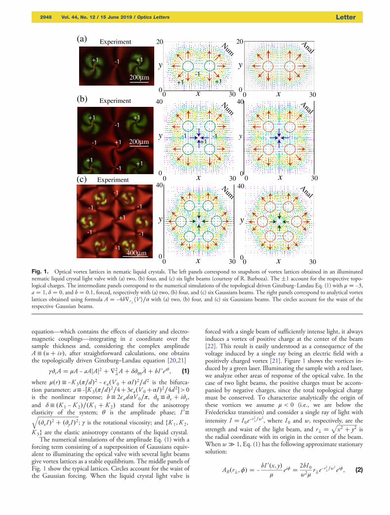
forcing term consisting of a superposition of Gaussians equiv-alent to illuminating the optical valve with several light beamsgive vortex lattices as a stable equilibrium. The middle panels ofFig. 1 show the typical lattices. Circles account for the waist ofthe Gaussian forcing. When the liquid crystal light valve is
forced with a single beam of sufficiently intense light, it alwaysinduces a vortex of positive charge at the center of the beam[22]. This result is easily understood as a consequence of thevoltage induced by a single ray being an electric field with apositively charged vortex [21]. Figure 1 shows the vortices in-duced by a green laser. Illuminating the sample with a red laser,we analyze other areas of response of the optical valve. In thecase of two light beams, the positive charges must be accom-panied by negative charges, since the total topological chargemust be conserved. To characterize analytically the origin ofthese vortices we assume μ < 0 (i.e., we are below theFréedericksz transition) and consider a single ray of light withintensity I � I 0e−r
2⊥∕w
2, where I0 and w, respectively, are the
strength and waist of the light beam, and r⊥ �ffiffiffiffiffiffiffiffiffiffiffiffiffiffiffix2 � y2
pis
the radial coordinate with its origin in the center of the beam.When w ≫ 1, Eq. (1) has the following approximate stationarysolution:
AR�r⊥,ϕ� � −bI 0�x, y�
μeiϕ � 2bI 0
w2μr⊥e−r
2⊥∕w
2eiϕ, (2)
x0 30
20
0
y200µm
Experiment NumAnal
(a)
Experiment(b) 40
0
y
200µm
0
y
20
0
y
x0 3040
x0 30 x0 3040
0
y
x0 30
(c)
400µm
Experiment
x0 30
40
0
y
Num
Num
Anal
Anal
220202020200020020000000000000µµµµµµµµµµmmmmmm
200µm
Fig. 1. Optical vortex lattices in nematic liquid crystals. The left panels correspond to snapshots of vortex lattices obtained in an illuminatednematic liquid crystal light valve with (a) two, (b) four, and (c) six light beams (courtesy of R. Barboza). The �1 account for the respective topo-logical charges. The intermediate panels correspond to the numerical simulations of the topological driven Ginzburg–Landau Eq. (1) with μ � −3,a � 1, δ � 0, and b � 0.1, forced, respectively with (a) two, (b) four, and (c) six Gaussians beams. The right panels correspond to analytical vortexlattices obtained using formula A � −4b∇r⊥hV i∕α with (a) two, (b) four, and (c) six Gaussians beams. The circles account for the waist of therespective Gaussian beams.
2948 Vol. 44, No. 12 / 15 June 2019 / Optics Letters Letter
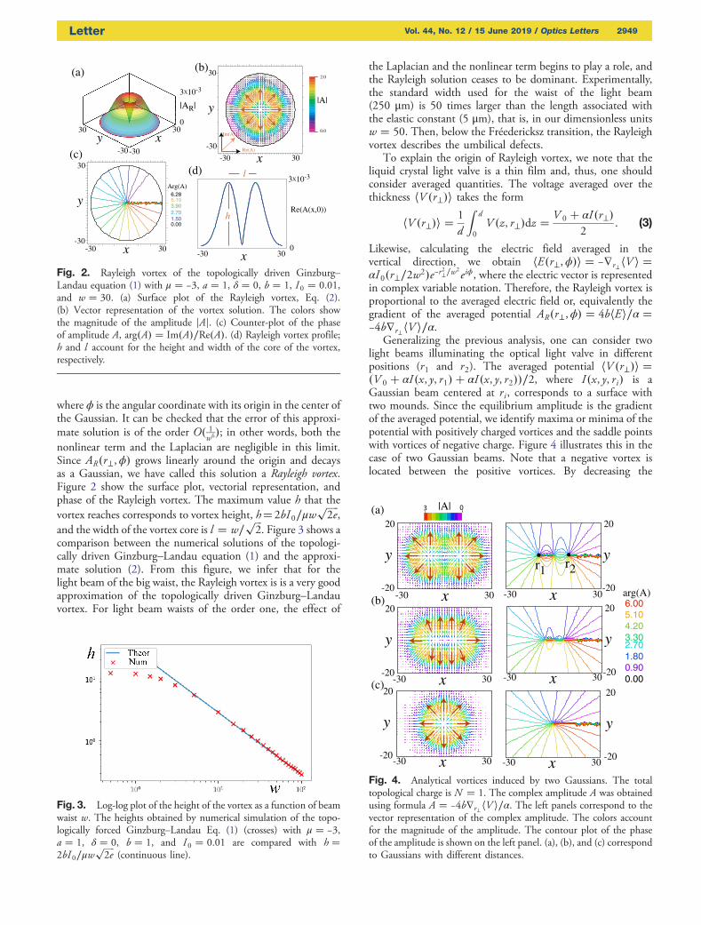
where ϕ is the angular coordinate with its origin in the center ofthe Gaussian. It can be checked that the error of this approxi-mate solution is of the order O� 1
w6�; in other words, both thenonlinear term and the Laplacian are negligible in this limit.Since AR�r⊥,ϕ� grows linearly around the origin and decaysas a Gaussian, we have called this solution a Rayleigh vortex.Figure 2 show the surface plot, vectorial representation, andphase of the Rayleigh vortex. The maximum value h that thevortex reaches corresponds to vortex height, h�2bI0∕μw
ffiffiffiffiffi2e
p,
and the width of the vortex core is l � w∕ffiffiffi2
p. Figure 3 shows a
comparison between the numerical solutions of the topologi-cally driven Ginzburg–Landau equation (1) and the approxi-mate solution (2). From this figure, we infer that for thelight beam of the big waist, the Rayleigh vortex is is a very goodapproximation of the topologically driven Ginzburg–Landauvortex. For light beam waists of the order one, the effect of
the Laplacian and the nonlinear term begins to play a role, andthe Rayleigh solution ceases to be dominant. Experimentally,the standard width used for the waist of the light beam(250 μm) is 50 times larger than the length associated withthe elastic constant (5 μm), that is, in our dimensionless unitsw � 50. Then, below the Fréedericksz transition, the Rayleighvortex describes the umbilical defects.
To explain the origin of Rayleigh vortex, we note that theliquid crystal light valve is a thin film and, thus, one shouldconsider averaged quantities. The voltage averaged over thethickness hV �r⊥�i takes the form
hV �r⊥�i �1
d
Zd
0
V �z, r⊥�dz �V 0 � αI�r⊥�
2: (3)
Likewise, calculating the electric field averaged in thevertical direction, we obtain hE�r⊥,ϕ�i � −∇r⊥hV i �αI0�r⊥∕2w2�e−r2⊥∕w2
eiϕ, where the electric vector is representedin complex variable notation. Therefore, the Rayleigh vortex isproportional to the averaged electric field or, equivalently thegradient of the averaged potential AR�r⊥,ϕ� � 4bhEi∕α �−4b∇r⊥hV i∕α.
Generalizing the previous analysis, one can consider twolight beams illuminating the optical light valve in differentpositions (r1 and r2). The averaged potential hV �r⊥�i ��V 0 � αI�x, y, r1� � αI�x, y, r2��∕2, where I�x, y, ri� is aGaussian beam centered at ri, corresponds to a surface withtwo mounds. Since the equilibrium amplitude is the gradientof the averaged potential, we identify maxima or minima of thepotential with positively charged vortices and the saddle pointswith vortices of negative charge. Figure 4 illustrates this in thecase of two Gaussian beams. Note that a negative vortex islocated between the positive vortices. By decreasing the
x-30-30
3030y
0
3X10⁻³
|AR|
(a) 2.0
0.0
(b)
x-30
-30
30
y
Re(A)
Im(A)
|A|
30
kn
6.28 5.10 3.90 2.70 1.50 0.00
(c)
x-30 30-30
30
yArg(A)
(d)
x-30 300
3X10⁻³
Re(A(x,0))
l
h
Fig. 2. Rayleigh vortex of the topologically driven Ginzburg–Landau equation (1) with μ � −3, a � 1, δ � 0, b � 1, I 0 � 0.01,and w � 30. (a) Surface plot of the Rayleigh vortex, Eq. (2).(b) Vector representation of the vortex solution. The colors showthe magnitude of the amplitude jAj. (c) Counter-plot of the phaseof amplitude A, arg�A� � Im�A�∕Re�A�. (d) Rayleigh vortex profile;h and l account for the height and width of the core of the vortex,respectively.
Fig. 3. Log-log plot of the height of the vortex as a function of beamwaist w. The heights obtained by numerical simulation of the topo-logically forced Ginzburg–Landau Eq. (1) (crosses) with μ � −3,a � 1, δ � 0, b � 1, and I 0 � 0.01 are compared with h �2bI0∕μw
ffiffiffiffiffi2e
p(continuous line).
x-30 30-20
20
y
x-30 30-20
20
y
x-30 30-20
20
y n
6.00 5.10 4.20 3.30 2.70 1.80 0.90 0.00
-20
20
y
x-30 30
x-30 30-20
20
y ft
x-30 30-20
20
y
|A|
arg(A)
(a)
(b)
(c)
r1 r2
Fig. 4. Analytical vortices induced by two Gaussians. The totaltopological charge is N � 1. The complex amplitude A was obtainedusing formula A � −4b∇r⊥hV i∕α. The left panels correspond to thevector representation of the complex amplitude. The colors accountfor the magnitude of the amplitude. The contour plot of the phaseof the amplitude is shown on the left panel. (a), (b), and (c) correspondto Gaussians with different distances.
Letter Vol. 44, No. 12 / 15 June 2019 / Optics Letters 2949
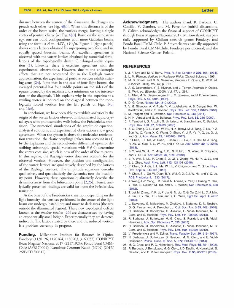
distance between the centers of the Gaussians, the charges ap-proach each other [see Fig. 4(b)]. When this distance is of theorder of the beam waist, the vortices merge, leaving a singlevortex of positive charge [see Fig. 4(c)]. Based on the same strat-egy, one can build configurations with more Gaussian beamsusing the formula A � −4b∇r⊥hV i∕α. Figure 1 (right panels)shows vortex lattices obtained by superposing two, four, and sixequally spaced Gaussian beams. An excellent agreement isobserved with the vortex lattices obtained by numerical simu-lations of the topologically driven Ginzburg–Landau equa-tion (1). Likewise, there is excellent agreement with theexperimental observations. However, due to the anisotropiceffects that are not accounted for in the Rayleigh vortexapproximation, the experimental positive vortices exhibit swirl-ing arms [24]. Note that in the case of four light beams, theaveraged potential has four saddle points on the sides of thesquare formed by the maxima and a minimum on the intersec-tion of the diagonals. This explains why in the experiment aswirling vortex is induced on the diagonal between the topo-logically forced vortices [see the left panels of Figs. 1(b)and 1(c)].
In conclusion, we have been able to establish analytically theorigin of the vortex lattices observed in illuminated liquid crys-tal layers with photosensitive walls below the Fréedericksz tran-sition. The numerical simulations of the amplitude equation,analytical solutions, and experimental observations show goodagreement. When the system is above the molecular reorienta-tion transition, the elastic couplings (taken into account in (1)by the Laplacian and the second-order differential operator de-scribing anisotropic spatial variations with δ ≠ 0) determinethe vortex core size, which is now of the order of few microns.In this regime, the Rayleigh vortex does not account for theobserved vortices. However, the position and configurationof the vortex lattices are qualitatively described by the latticesof the Rayleigh vortices. The amplitude equations describequalitatively and quantitatively the dynamics near the instabil-ity point. However, these equations qualitatively describe thedynamics away from the bifurcation point [2,25]. Hence, ana-lytically presented findings are valid far from the Fréedericksztransition.
At the onset of the Fréedericksz transition, depending on thelight intensity, the vortices positioned in the center of the lightbeam can undergo instabilities and move to dark areas (the areaoutside the illuminated region). These new topological defectsknown as the shadow vortices [26] are characterized by havingan exponentially small height. Experimentally they are detectedindirectly. The lattice created by these and the induced vorticesis a problem currently in progress.
Funding. Millennium Institute for Research in Optics;Fondecyt (1130126, 1170164, 1180903, 3160055); CONICYTBecas Magister Nacional 2017 (22171924); Fondo Basal CMM-Chile (AFB170001); Narodowe Centrum Nauki (NCN) (2017/26/E/ST1/00817).
Acknowledgment. The authors thank R. Barboza, C.Castillo, V. Zambra, and M. Ferre for fruitful discussions.E. Calisto acknowledges the financial support of CONICYTthrough Becas Magister Nacional 2017. M. Kowalczyk was par-tially supported by Chilean research grants Fondecyt andFondo Basal CMM-Chile. P. Smyrnelis was partially supportedby Fondo Basal CMM-Chile, Fondecyt postdoctoral, and theNational Science Centre, Poland.
REFERENCES
1. J. F. Nye and M. V. Berry, Proc. R. Soc. London A 336, 165 (1974).2. L. M. Pismen, Vortices in Nonlinear Fields (Oxford Science, 1999).3. M. S. Soskin and M. V. Vasnetov, Progress in Optics, E. Wolf, ed.
(Elsevier, 2001), Vol. 42, p. 219.4. A. S. Desyatnikov, Y. S. Kivshar, and L. Torner, Progress in Optics,
E. Wolf, ed. (Elsevier, 2005), Vol. 47, p. 291.5. L. Allen, M. W. Beijersbergen, R. J. C. Spreeuw, and J. P. Woerdman,
Phys. Rev. A 45, 8185 (1992).6. D. G. Grier, Nature 424, 810 (2003).7. V. G. Shvedov, A. V. Rode, Y. V. Izdebskaya, A. S. Desyatnikov, W.
Krolikowski, and Y. S. Kivshar, Phys. Rev. Lett. 105, 118103 (2010).8. M. Padgett and R. Bowman, Nat. Photonics 5, 343 (2011).9. H. H. Arnaut and G. A. Barbosa, Phys. Rev. Lett. 85, 286 (2000).10. F. Tamburini, G. Anzolin, G. Umbriaco, A. Bianchini, and C. Barbieri,
Phys. Rev. Lett. 97, 163903 (2006).11. Z. G. Zheng, C. L. Yuan, W. Hu, H. K. Bisoyi, M. J. Tang, Z. Liu, P. Z.
Sun, W. Q. Yang, X. Q. Wang, D. Shen, Y. Li, F. Ye, Y. Q. Lu, G. Li,and Q. Li, Adv. Mater. 29, 1703165 (2017).
12. P. Chen, L. L. Ma, W. Duan, J. Chen, S. J. Ge, Z. H. Zhu, M. J. Tang,R. Xu, W. Gao, T. Li, W. Hu, and Y. Q. Lu, Adv. Mater. 30, 1705865(2018).
13. B. Y. Wei, W. Hu, Y. Ming, F. Xu, S. Rubin, J. G. Wang, V. Chigrinov,and Y. Q. Lu, Adv. Mater. 26, 1590 (2013).
14. B. Y. Wei, S. Liu, P. Chen, S. X. Qi, Y. Zhang, W. Hu, Y. Q. Lu, andJ. L. Zhao, Appl. Phys. Lett. 112, 121101 (2018).
15. P. Chen, S. J. Ge, L. L. Ma, W. Hu, V. Chigrinov, and Y. Q. Lu, Phys.Rev. Appl. 5, 044009 (2016).
16. P. Chen, S. J. Ge, W. Duan, B. Y. Wei, G. X. Cui, W. Hu, and Y. Q. Lu,ACS Photonics 4, 1333 (2017).
17. J. Wang, J.-Y. Yang, I. M. Fazal, N. Ahmed, Y. Yan, H. Huang, Y. Ren,Y. Yue, S. Dolinar, M. Tur, and A. E. Willner, Nat. Photonics 6, 488(2012).
18. T. Lei, M. Zhang, Y. R. Li, P. Jia, G. N. Liu, X. G. Xu, Z. H. Li, C. J. Min,J. Lin, C. Y. Yu, H. B. Niu, and X. C. Yuan, Light Sci. Appl. 4, e257(2015).
19. L. Stoyanov, G. Maleshkov, M. Zhekova, I. Stefanov, D. N. Neshev,G. G. Paulus, and A. Dreischuh, J. Opt. Soc. Am. B 35, 402 (2018).
20. R. Barboza, U. Bortolozzo, G. Assanto, E. Vidal-Henriquez, M. G.Clerc, and S. Residori, Phys. Rev. Lett. 111, 093902 (2013).
21. R. Barboza, U. Bortolozzo, M. G. Clerc, S. Residori, and E. Vidal-Henriquez, Adv. Opt. Photonics 7, 635 (2015).
22. R. Barboza, U. Bortolozzo, G. Assanto, E. Vidal-Henriquez, M. G.Clerc, and S. Residori, Phys. Rev. Lett. 109, 143901 (2012).
23. V. Freedericksz and V. Zolina, Trans. Faraday Soc. 29, 919 (1927).24. R. Barboza, U. Bortolozzo, S. Residori, M. G. Clerc, and E. Vidal-
Henriquez, Philos. Trans. R. Soc. A. 372, 20140019 (2014).25. M. C. Cross and P. C. Hohenberg, Rev. Mod. Phys. 65, 851 (1993).26. R. Barboza, U. Bortolozzo, M. G. Clerc, J. D. Davila, M. Kowalczyk, S.
Residori, and E. Vidal-Henriquez, Phys. Rev. E 93, 050201 (2016).
2950 Vol. 44, No. 12 / 15 June 2019 / Optics Letters Letter