
on Manual - Palm Harbor Homes | Manufactured Homes, … · on Manual Palm Harbor Homes, Inc....
106
INSTALLATION MANUAL Palm Harbor Homes, Inc. September 22, 2008 Manufactured Home Installation Manual A copy of this manual must remain with the home for future reference by the occupant. Effective Date: October 20, 2008
Transcript of on Manual - Palm Harbor Homes | Manufactured Homes, … · on Manual Palm Harbor Homes, Inc....

Inst
all
atIo
n M
an
ual
Palm Harbor Homes, Inc.september 22, 2008
Manufactured Home Installation Manual
A copy of this manual must remain with the home for future reference by the occupant.
Effective Date: October 20, 2008
PALM
HA
RB
OR
HO
MES IN
STALLA
TION
MA
NU
AL
9/22/08 Palm Harbor Homes, Inc. 1
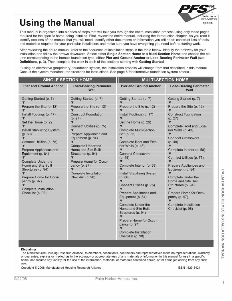
Using the Manual This manual is organized into a series of steps that will take you through the entire installation process using only those pagesrequired for the specific home being installed. First, review the entire manual, including the Introduction chapter. As you read it, identify sections of the manual that you will need; identify other documents or information you will need; construct lists of toolsand materials required for your particular installation; and make sure you have everything you need before starting work.
After reviewing the entire manual, refer to the sequence of installation steps in the table below. Identify the pathway for yourinstallation and follow the arrows downward. Select either Single Section Home or a Multi-Section Home and choose the col-umn corresponding to the home’s foundation type, either Pier and Ground Anchor or Load-Bearing Perimeter Wall (see Definitions, p. 3). Then complete the work in each of the sections starting with Getting Started.
If using an alternative (proprietary) foundation system, the installation process will change from that described in this manual.Consult the system manufacturer directions for instructions. See page 5 for alternative foundation system criteria.
SINGLE SECTION HOME MULTI-SECTION HOME Pier and Ground Anchor Load-Bearing Perimeter
WallPier and Ground Anchor Load-Bearing Perimeter
Wall
Getting Started (p. 7) Getting Started (p. 7) Getting Started (p. 7) Getting Started (p. 7)
DisclaimerThe Manufactured Housing Research Alliance, its members, consultants, contractors and representatives make no representations, warranty or guarantee, express or implied, as to the accuracy or appropriateness of any materials or information in this manual for use in a specific home, nor assume any liability for the use of the information, methods, or materials contained herein, or for damages arising from any such use.Copyright © 2008 Manufactured Housing Research Alliance ISSN 1529-3424
Prepare the Site (p. 12)
Install Footings (p. 17)
Set the Home (p. 29)
Install Stabilizing System (p. 60)
Connect Utilities (p. 75)
Prepare Appliances and Equipment (p. 84)
Complete Under the Home and Site Built Structures (p. 94)
Prepare Home for Occu-pancy (p. 97)
Complete Installation Checklist (p. 98)
Prepare the Site (p. 12)
Construct Foundation (p. 27)
Connect Utilities (p. 75)
Prepare Appliances and Equipment (p. 84)
Complete Under the Home and Site Built Structures (p. 94)
Prepare Home for Occu-pancy (p. 97)
Complete Installation Checklist (p. 98)
Prepare the Site (p. 12) Prepare the Site (p. 12)
Install Footings (p. 17) Construct Foundation (p. 27)
Set the Home (p. 29)Complete Roof and Exte-rior Walls (p. 43)Complete Multi-Section
Set (p. 35)Connect Crossovers(p. 48)Complete Roof and Exte-
rior Walls (p. 43)Complete Interior (p. 58)
Connect Crossovers(p. 48) Connect Utilities (p. 75)
Complete Interior (p. 58) Prepare Appliances and Equipment (p. 84)
Install Stabilizing System (p. 60) Complete Under the
Home and Site Built Structures (p. 94)Connect Utilities (p. 75)
Prepare Appliances and Equipment (p. 84)
Prepare Home for Occu-pancy (p. 97)
Complete Under the Home and Site Built Structures (p. 94)
Complete Installation Checklist (p. 98)
Prepare Home for Occu-pancy (p. 97)
Complete Installation Checklist (p. 98)
#05
Conforms toHUD MHCSS
10/20/08
IntroductionThis installation manual contains instructions that must be followed for the proper installation of the home. It complies with the HUD Model Manufactured Home Installation Standards. Please read all instructions and any other documents (includ-ing addendum pages and supplements) that may apply to the specific home prior to commencing site work or installation.
This installation manual covers permits and site work through final inspection of the installation. It covers both single and multi-section homes installed over pier and anchor, load bearing crawl space walls and basement foundations. It contains instructions, including specifications and procedures, for the set and hookup of manufactured homes to be used as single-family dwellings.
The importance of correct installation cannot be over-emphasized. Correct installation is absolutely essential to home-owner satisfaction and the structural integrity of the home. All instructions must be followed to provide the customer with a safe, quality home.
No manual can cover all circumstances that may exist for certain home designs or building sites. For questions, further clarification, or if you encounter conditions at the site or in the design of the home or its foundation not covered by this manual, please contact the manufacturer (see Resources, p. 2), a registered engineer, or registered architect.
Supplemental addendum pages may be included with this manual. Supplements include requirements not covered in this manual or that supercede the manual instructions.
Once the home installation is complete, leave this manual with the home.
IMPORTANT NOTICES The home manufacturer is not responsible for installation or for the materials supplied by the set-up crew at the
time of installation. The installer may be responsible for any deviations from the installation instructions of this manual.
To keep the home in compliance with its warranty, the home installation must follow the procedures described in this manual or other procedures approved by the manufacturer. Deviation from the instructions in this manual may void the home’s warranty. Any alterations or changes to the home shall be approved by a registered engi-neer or registered architect and may still be subject to warranty violations.
When an installer does not provide support and anchorage in accordance with the approved manufacturer's in-stallation instructions, or encounters site conditions (such as areas that are subject to flood damage or high seismic risk) or other conditions that prevent the use of the instructions provided in this manual, the installer must obtain special site-specific instructions from the manufacturer or use a design approved by a registered engineer or registered architect.
The installer must possess a valid installation license as a manufactured home installer. If the installer identifies failures of the home to comply with the Federal Manufactured Home Construction and
Safety Standards (the HUD Code), the installer must notify the manufacturer and retailer.
SAFETYThere are potential hazards associated with the installation of a manufactured home. Home installers are licensed, and as experienced professionals, should recognize these hazards, be qualified to work with them, and be capable of providing safe work practices and equipment that minimize the risks of injury.
Only qualified persons should install a manufactured home. As qualified professionals in the field of manufactured home installation, installers are the experts and must be aware of the hazards and conditions faced. Warnings are published throughout this manual as reminders. These reminders may not cover all hazards, all potential hazards, or all possible consequences of improper or unsafe installation practices.
Construction crews should be trained in the skills required and be supervised by experienced personnel. Installers should regularly inspect work performed by crews and subcontractors.
Obey OSHA regulations, particularly those related to home construction, such as Title 29 Code of Regulations Part 1926. For copies of OSHA regulations, call (202) 512-1800 or visit www.osha.gov on the web.
RESOURCESManufacturer contact information: See Back Cover for Building Center information
NameAddressTelephone
Palm Harbor Homes, Inc. 9/22/08
Fax
2
#05
Conforms toHUD MHCSS
10/20/08
PALM
HA
RB
OR
HO
MES IN
STALLA
TION
MA
NU
AL
9/22/08 Palm Harbor Homes, Inc. 3
BASEMENT. A load-bearing perimeter wall foundation that includes habitable space (finished or unfinished, heated or unheated) partly or completely below grade.
CRAWLSPACE. The space underneath the home’s floor system, enclosed with either load- or non-load bearing perimeter walls. The ground may be covered with a concrete slab or by a plastic ground cover. Crawlspace walls must be vented.
Website
Office of Regulatory Affairs and Manufactured Housing US Department of Housing and Urban Development 451 Seventh Street, SW, Room 9164 Washington, DC 20410-8000 Telephone: (202) 708-6423 or (800) 927-2891 FAX: (202) 708-4213
State Administrative Agencies A list of SAAs may be found on the web at www.hud.gov or by contacting the Office of Regulatory Affairs and Manu-factured Housing.
FEDERAL PREEMPTION This home was engineered, constructed, and inspected in conformance with the Federal Manufactured Home Construc-tion and Safety Standards of the US Department of Housing and Urban Development (24 CFR Part 3280, commonly re-ferred to as the “HUD Code”) in effect on the date of manufacture. These Standards set forth minimum requirements for the design and construction of manufactured homes designed to be used as dwellings.
Individual states, counties and cities shall have no authority to establish standards regarding the construction or safety of a manufactured home. A metal certification label is affixed to each section of the home to certify that it has been con-structed and inspected to comply with these Standards. The design plans and in-plant construction of all homes are in-spected by independent third party agencies to assure compliance with the Standards.
The installation of the home and any alterations made to the home shall conform to the requirements of the Federal Manufactured Home Construction and Safety Standards and the HUD Model Manufactured Home Installation Standards. These installation instructions are minimum requirements. Applicable local or state laws may have more stringent installa-tion requirements than outlined in this manual and must be followed. Consult with the local authority having jurisdiction (LAHJ) for regulations that may require licenses and/or permits or which may affect procedures described in this manual.
DEFINITIONSANCHOR ASSEMBLY. Any device or other means designed to transfer loads to the ground.
ANCHORING EQUIPMENT. Ties, straps, cables, turnbuckles, chains, and other approved components, including tension-ing devices that are used to secure a manufactured home to anchor assemblies.
ANCHORING SYSTEM. A combination of anchoring equipment and anchor assemblies that will, when properly designed and installed, resist the uplift, overturning, and lateral forces on the manufactured home.
CROSSOVERS. Utility interconnections between sections of multi-section homes, including heating and cooling ducts, electrical circuits, and water pipes, drain plumbing, and gas lines.
DATA PLATE. An information sheet located at the main electrical panel, in the utility room, in a bedroom closet, or in a cabinet in the kitchen. It contains a unique identification number and identifies the wind zone, roof load zone, and cli-matic zone for which the home was constructed.
DIAGONAL TIE. A tie intended to resist horizontal or shear forces, but which may resist vertical, uplift, and overturning forces.
FOOTING. That portion of the support system that transmits loads directly to the soil.
GROUND ANCHOR. A specific anchoring assembly device designed to transfer home loads to the ground.
H-BEAM. Steel H-beams are often used to support a home over a basement or crawlspace. They span across the foun-dation from sidewall to sidewall, typically with an intermediate support pier and footing (typically in the center point re-sulting in a line of piers under the centerline of a double section home).
INFORMATION PACKET. A set of important documents provided with the home including warranties, information on high wind coverage, and other features of the specific home.
INSTALLATION LICENSE. The proof that an installer meets the requirements for installing manufactured homes under the HUD-administered installation program.
#05
Conforms toHUD MHCSS
10/20/08
LABELED. Equipment or materials to which has been attached a label, symbol, or other identifying mark of a certified testing laboratory, inspection agency, or other an organization concerned with product evaluation. The label indicates compliance with nationally recognized standards or tests to determine suitable usage in a specified manner.
LISTED OR CERTIFIED. Included in a list published by a nationally recognized testing laboratory, inspection agency, or other organization concerned with product evaluation that maintains periodic inspection of production of listed equip-ment or materials, and whose listing states either that the equipment or material meets nationally recognized stan-dards or has been tested and found suitable for use in a specified manner.
LOAD-BEARING PERIMETER WALL FOUNDATION. A support system for the home whereby the home is mechanically fastened to a structural wall(s) that transfers gravity, lateral, and uplift loads to the ground.
LOCAL AUTHORITY HAVING JURISDICTION (LAHJ). The state, city, county, municipality, utility, or organization that has local responsibilities that must be complied with during the installation of a manufactured home.
MUST. Indicates a mandatory requirement.
N/A. Indicates not applicable.
PIER. That portion of the support system between the footing and the manufactured home, exclusive of shims. Types of piers include, but are not limited to: (1) manufactured steel stands; (2) pressure-treated wood; (3) manufactured con-crete stands; (4) concrete blocks; and (5) portions of foundation walls.
PIER AND GROUND ANCHOR FOUNDATION. A support system for the home that employs piers under the chassis and other locations to support gravity loads and employs ground anchors and tie downs (the stabilizing system) to resist lateral and uplift loads.
PERIMETER BLOCKING. Regularly spaced piers supporting the sidewalls and marriage line of the home. Some homes require perimeter blocking in addition to supports under the home’s frame.
QUALIFIED. Has the necessary knowledge and skills gained from experience and training that will allow performance of the job safely, competently, and in accordance with all applicable codes, standards, rules, and regulations. Meets all necessary qualification tests including any license and certification requirements that may be in effect in the area where the home will be installed.
RAMADA. Any freestanding roof or shade structure, installed or erected over a manufactured home or any portion thereof.
SHOULD. Indicates a recommendation that is strongly advised but not mandatory.
SHALL. Indicates a mandatory requirement.
SITE FOR A MANUFACTURED HOME. A designated parcel of land designed for the accommodation of one manufac-tured home, its accessory buildings or structures, and accessory equipment, for the exclusive use of the occupants of the home.
SKIRTING. A weather-resistant material used to enclose the perimeter, under the living area of the home, from the bottom of the manufactured home to grade.
STABILIZING SYSTEM. All components of the anchoring and support systems, such as piers, footings, ties, anchoring equipment, anchoring assemblies, or any other equipment, materials and methods of construction, that support and secure the manufactured home to the ground.
SUPPORT SYSTEM. Pilings, columns, a combination of footings, piers, foundation walls, caps, and shims and any com-bination thereof that will, when properly installed, support and secure the manufactured home to the ground.
TIE. Straps, cable, or securing devices used to connect the manufactured home to anchoring assemblies.
UTILITY CONNECTION. The connection of the manufactured home to utilities that include, but are not limited to, electric-ity, water, sewer, gas, or fuel oil.
VERTICAL TIE. A tie intended to resist uplifting and overturning forces.
WIND ZONE. The areas designated on the Basic Wind Zone Map, as further defined by the Manufactured Home Con-struction and Safety Standards.
Palm Harbor Homes, Inc. 9/22/08
ENGINEER’S STAMP Certain pages of this manual display the seal of a registered engineer. Federal guidelines only require the seal from one state to be displayed, but the details herein apply to all states.
4
#05
Conforms toHUD MHCSS
10/20/08
PALM
HA
RB
OR
HO
MES IN
STALLA
TION
MA
NU
AL
9/22/08 Palm Harbor Homes, Inc. 5
SYMBOLS USED IN THE MANUAL
This icon indicates an important warning. It is critical to heed these warnings.
This icon indicates a recommended best practice. While not required, following these practices will result in a superior installation, reducing the chance that cosmetic or dura-bility related complaints might arise.
ABBREVIATIONS ABS Acrylonitrile Butadiene Styrene max. Maximum
ANSI American National Standards Insti-tute MHCSS Manufactured Home Construction and
Safety Standards
APA American Plywood Association min. Minimum
ASTM American Society for Testing and Ma-terials mph Mile(s) per hour
AWPA American Wood Preservers Associa-tion NEC National Electric Code
CFM Cubic feet per minute NFIP National Flood Insurance Program
CFR Code of Federal Regulations NFPA National Fire Protection Association
DWV Drain, Waste, Vent o.c. On center
EMT Electrical metallic tubing OSHA Occupational Safety and Health Admini-stration
FEMA Federal Emergency Management Agency oz Ounce(s)
ft Foot/feet p. Page
ga Gauge psf Pounds per square foot
HUD US Department of Housing and Ur-ban Development psi Pounds per square inch
in Inch(es) SAA State Administrative Agency
LAHJ Local Authority Having Jurisdiction sq ft Square foot/feet
lb(s) Pound(s)
ALTERNATIVE FOUNDATION SYSTEMS Alternative foundation systems or designs are permitted if they are approved by the home manufacturer and the manufac-turer’s DAPIA, and are in accordance with either of the following:
Systems or designs are manufactured and installed in accordance with their listings by a nationally recognized testing agency based on a nationally recognized testing protocol; or
System designs are prepared by a registered engineer or a registered architect or tested and certified by a regis-tered engineer or registered architect in accordance with acceptable engineering practice and are manufactured and installed so as not to take the home out of compliance with the Manufactured Home Construction and Safety Standards.
DISPLAY AND STORAGE OF THE HOME WEATHER PROTECTION If the installation is not started immediately upon delivery of the home, the retailer and/or installer has the responsibility to ensure the exterior weather protection covering of marriage walls and the roof of homes with hinged roofs has not been damaged during shipment. Inspect the home immediately upon the delivery and frequently during storage. Promptly repair tears in the home closure materials to prevent damage from the elements. Inspect and repair roof shingles and siding as needed.
#05
Conforms toHUD MHCSS
10/20/08
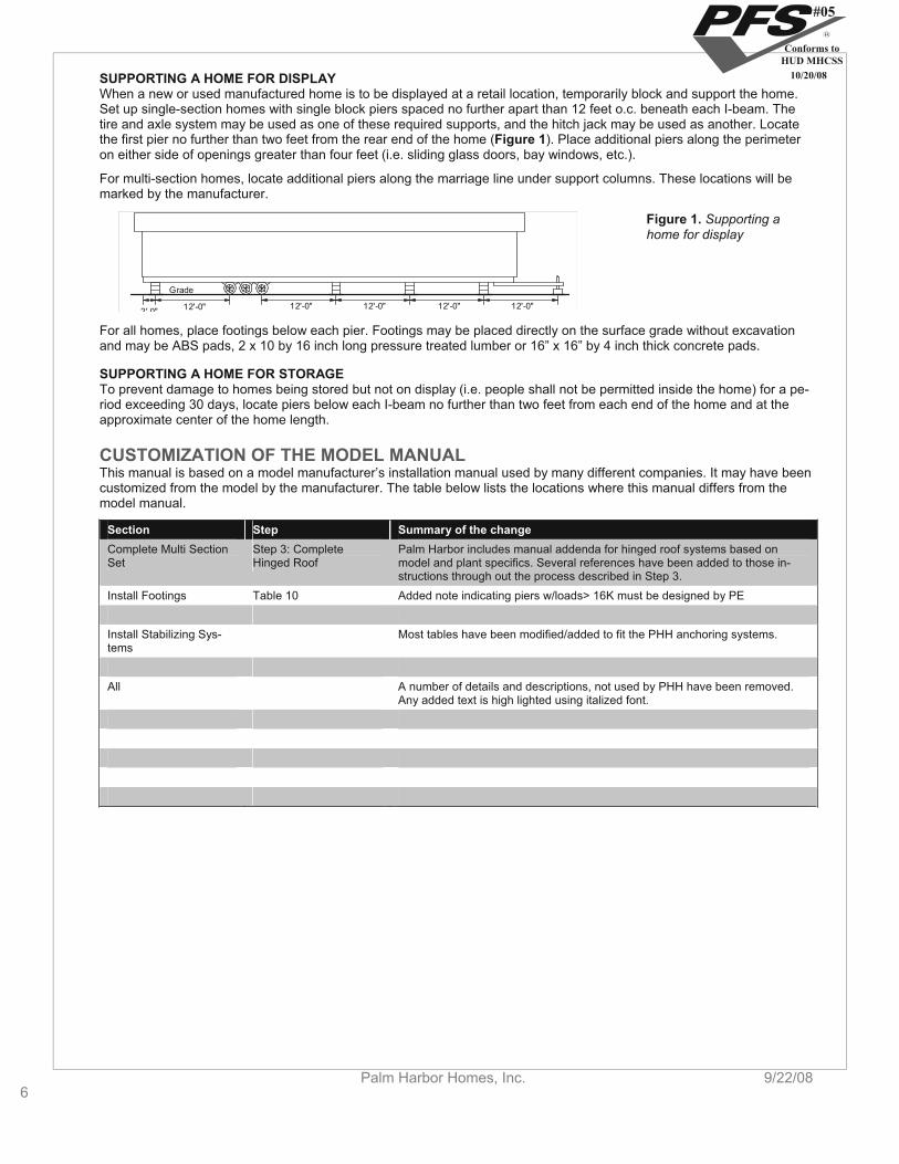
SUPPORTING A HOME FOR DISPLAY When a new or used manufactured home is to be displayed at a retail location, temporarily block and support the home. Set up single-section homes with single block piers spaced no further apart than 12 feet o.c. beneath each I-beam. The tire and axle system may be used as one of these required supports, and the hitch jack may be used as another. Locate the first pier no further than two feet from the rear end of the home (Figure 1). Place additional piers along the perimeter on either side of openings greater than four feet (i.e. sliding glass doors, bay windows, etc.).
For multi-section homes, locate additional piers along the marriage line under support columns. These locations will be marked by the manufacturer.
12'-0"2' 0" 12'-0" 12'-0" 12'-0" 12'-0"
Grade
Figure 1. Supporting a home for display
For all homes, place footings below each pier. Footings may be placed directly on the surface grade without excavation and may be ABS pads, 2 x 10 by 16 inch long pressure treated lumber or 16” x 16” by 4 inch thick concrete pads.
SUPPORTING A HOME FOR STORAGE To prevent damage to homes being stored but not on display (i.e. people shall not be permitted inside the home) for a pe-riod exceeding 30 days, locate piers below each I-beam no further than two feet from each end of the home and at the approximate center of the home length.
CUSTOMIZATION OF THE MODEL MANUAL This manual is based on a model manufacturer’s installation manual used by many different companies. It may have been customized from the model by the manufacturer. The table below lists the locations where this manual differs from the model manual.
Step Summary of the change Section Step 3: Complete Hinged Roof
Palm Harbor includes manual addenda for hinged roof systems based on model and plant specifics. Several references have been added to those in-structions through out the process described in Step 3.
Complete Multi Section Set
Install Footings Table 10 Added note indicating piers w/loads> 16K must be designed by PE
Install Stabilizing Sys-tems
Most tables have been modified/added to fit the PHH anchoring systems.
All A number of details and descriptions, not used by PHH have been removed. Any added text is high lighted using italized font.
6Palm Harbor Homes, Inc. 9/22/08
#05
Conforms toHUD MHCSS
10/20/08

PALM
HA
RB
OR
HO
MES
INSTA
LLATIO
N M
AN
UA
LGetting Started
9/22/08 Palm Harbor Homes, Inc. 7
Getting Started This chapter covers a few steps that, taken now, will avoid problems later in the installation process.
Follow the Steps below:
STEP 1. LOCATE THE DATA PLATE (p. 7)
STEP 2. CONFIRM WIND ZONE (p. 7)
STEP 3. CONFIRM THERMAL ZONE (p. 8)
STEP 4. CONFIRM ROOF-LOAD ZONE (p. 9)
STEP 5. CHECK LOCAL CODES AND SECURE PERMITS (p. 10)
STEP 1. LOCATE THE DATA PLATE Locate the data plate inside the home (Figure 2), typically inside a kitchen cabinet door or on a wall panel or door face near the electrical panel, utility room, or bedroom closet.
Figure 2. Sample data plate
The information on the data plate will be used to verify that the home was designed for the proper location.
STEP 2. CONFIRM WIND ZONE From Table 1, identify the wind zone for the home. Verify that the home conforms to the following rules and any special requirements determined by the LAHJ.
No home may be located in a higher wind zone than that indicated on the data plate. (Example: a home designed for Wind Zone II cannot be placed in Wind Zone III.)
A home may be located in a lower wind zone than that indicated on the data plate. (Example: a home designed for Wind Zone II can be placed in either Wind Zone II or I.)
Homes located within 1,500 feet of the coastline in Wind Zones II and III must be designed to withstand exposure ‘D’ conditions. This will be indicated on the data plate.
If the home does not conform to these rules, contact the manufacturer immediately.
Site approprietness. If the site is not accessible, not appropriate for the planned support system or cannot be properly graded, notify the purchaser, the retailer and HUD, with the reasons why the site is unsuitable. Do not install the home until all issues are remedied.
#05
Conforms toHUD MHCSS
10/20/08

Getting Started
8Palm Harbor Homes, Inc. 9/22/08
PALM
HA
RB
OR
HO
MES
INST
ALL
ATI
ON
MA
NU
AL
TABLE 1. WIND ZONE BY LOCALITY Wind Zone I All areas except those areas listed below as being within Wind Zone II or III
Wind Zone II Alabama Counties of Baldwin and Mobile Florida All counties except those listed below as within Wind Zone III Georgia Counties of Bryan, Camden, Chatham, Glynn, Liberty, McIntosh Louisiana Parishes of Acadia, Allen, Ascension, Assumption, Calcasieu, Cameron, East Baton Rouge, East Feliciana,
Evangeline, Iberia, Iberville, Jefferson Davis, Lafayette, Livingston, Pointe Coupee, St. Helena, St. James, St. John the Baptist, St. Landry, St. Martin, St. Tammany, Tangipahoa, Vermillion, Washington, West Baton Rouge, and West Feliciana
Maine Counties of Hancock and Washington Massachusetts Counties of Barnstable, Bristol, Dukes, Nantucket, and Plymouth Mississippi Counties of George, Hancock, Harrison, Jackson, Pearl River, and Stone North Carolina Counties of Beaufort, Brunswick, Camden, Chowan, Columbus, Craven, Currituck, Jones, New Hanover, Onslow,
Pamlico, Pasquotank, Pender, Perquimans, Tyrrell, and Washington South Carolina Counties of Beaufort, Berkeley, Charleston, Colleton, Dorchester, Georgetown, Horry, Jasper, and Williamsburg Texas Counties of Aransas, Brazoria, Calhoun, Cameron, Chambers, Galveston, Jefferson, Kennedy, Kleberg, Mata-
gorda, Nueces, Orange, Refugio, San Patricio, and Willacy Virginia Cities of Chesapeake, Norfolk, Portsmouth, Princess Anne, and Virginia Beach
Wind Zone IIIHawaii Entire state Alaska Coastal regions (as determined by the 90 mph isotach on the ANSI/ASCE 7-88 map) Florida Counties of Broward, Charlotte, Collier, Dade, Franklin, Gulf, Hendry, Lee, Martin, Manatee, Monroe, Palm Beach,
Pinellas, and Sarasota Louisiana Parishes of Jefferson, La Fourche, Orleans, Plaquemines, St. Bernard, St. Charles, St. Mary, and Terrebonne North Carolina Counties of Carteret, Dare, and Hyde Other All regions of the U.S. Territories of American Samoa, Guam, Northern Mariana Islands, Puerto Rico, Trust Terri-
tory of the Pacific Islands, and the United States Virgin Islands
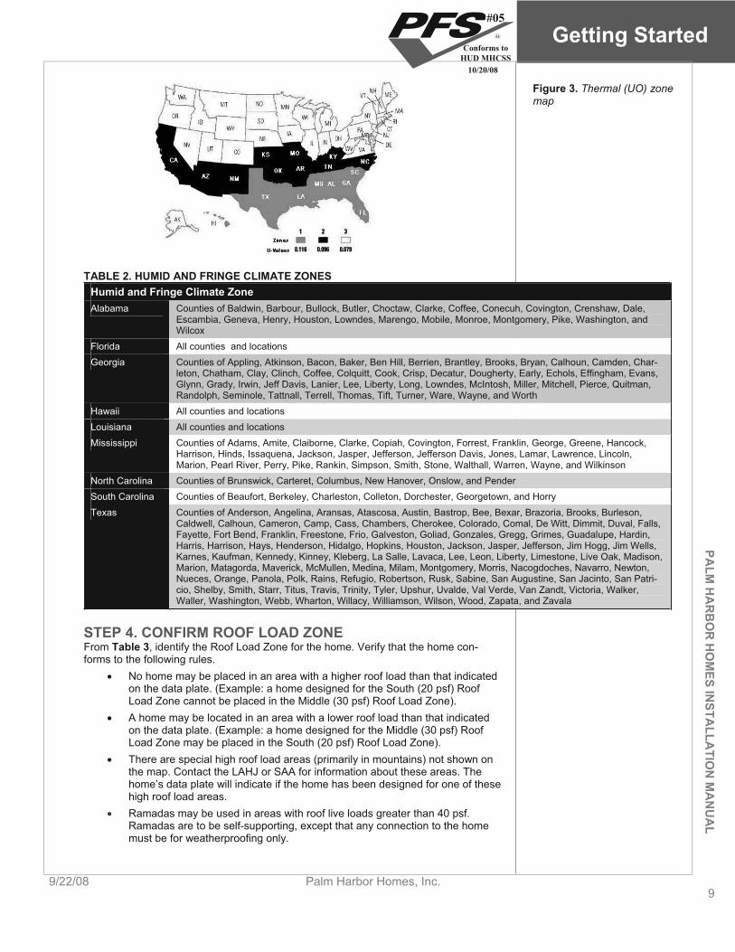
STEP 3. CONFIRM THERMAL ZONE From Figure 3, identify the thermal (UO) zone for the home. Verify that the home con-forms to the following rules.
No home may be located in an area with a higher thermal zone number than that indicated on the data plate. (Example: a home designed for Thermal Zone 2 cannot be placed in Thermal Zone 3.)
A home may be located in a lower thermal zone than that indicated on the data plate. (Example: a home designed for Thermal Zone 2 may be placed in either Thermal Zone 2 or 1.).
In no case may a home designated for installation in the "Humid & Fringe Climate," as identified on the data plate, be located outside of this region (Table 2).
If the home does not conform to these rules, contact the manufacturer immediately.
#05
Conforms toHUD MHCSS
10/20/08
PALM
HA
RB
OR
HO
MES
INSTA
LLATIO
N M
AN
UA
LGetting Started
9/22/08 Palm Harbor Homes, Inc. 9
Figure 3. Thermal (UO) zone map
TABLE 2. HUMID AND FRINGE CLIMATE ZONES Humid and Fringe Climate Zone Alabama Counties of Baldwin, Barbour, Bullock, Butler, Choctaw, Clarke, Coffee, Conecuh, Covington, Crenshaw, Dale,
Escambia, Geneva, Henry, Houston, Lowndes, Marengo, Mobile, Monroe, Montgomery, Pike, Washington, and Wilcox
Florida All counties and locations Georgia Counties of Appling, Atkinson, Bacon, Baker, Ben Hill, Berrien, Brantley, Brooks, Bryan, Calhoun, Camden, Char-
leton, Chatham, Clay, Clinch, Coffee, Colquitt, Cook, Crisp, Decatur, Dougherty, Early, Echols, Effingham, Evans, Glynn, Grady, Irwin, Jeff Davis, Lanier, Lee, Liberty, Long, Lowndes, McIntosh, Miller, Mitchell, Pierce, Quitman, Randolph, Seminole, Tattnall, Terrell, Thomas, Tift, Turner, Ware, Wayne, and Worth
Hawaii All counties and locations Louisiana All counties and locations Mississippi Counties of Adams, Amite, Claiborne, Clarke, Copiah, Covington, Forrest, Franklin, George, Greene, Hancock,
Harrison, Hinds, Issaquena, Jackson, Jasper, Jefferson, Jefferson Davis, Jones, Lamar, Lawrence, Lincoln, Marion, Pearl River, Perry, Pike, Rankin, Simpson, Smith, Stone, Walthall, Warren, Wayne, and Wilkinson
North Carolina Counties of Brunswick, Carteret, Columbus, New Hanover, Onslow, and Pender South Carolina Counties of Beaufort, Berkeley, Charleston, Colleton, Dorchester, Georgetown, and Horry Texas Counties of Anderson, Angelina, Aransas, Atascosa, Austin, Bastrop, Bee, Bexar, Brazoria, Brooks, Burleson,
Caldwell, Calhoun, Cameron, Camp, Cass, Chambers, Cherokee, Colorado, Comal, De Witt, Dimmit, Duval, Falls, Fayette, Fort Bend, Franklin, Freestone, Frio, Galveston, Goliad, Gonzales, Gregg, Grimes, Guadalupe, Hardin, Harris, Harrison, Hays, Henderson, Hidalgo, Hopkins, Houston, Jackson, Jasper, Jefferson, Jim Hogg, Jim Wells, Karnes, Kaufman, Kennedy, Kinney, Kleberg, La Salle, Lavaca, Lee, Leon, Liberty, Limestone, Live Oak, Madison, Marion, Matagorda, Maverick, McMullen, Medina, Milam, Montgomery, Morris, Nacogdoches, Navarro, Newton, Nueces, Orange, Panola, Polk, Rains, Refugio, Robertson, Rusk, Sabine, San Augustine, San Jacinto, San Patri-cio, Shelby, Smith, Starr, Titus, Travis, Trinity, Tyler, Upshur, Uvalde, Val Verde, Van Zandt, Victoria, Walker, Waller, Washington, Webb, Wharton, Willacy, Williamson, Wilson, Wood, Zapata, and Zavala
STEP 4. CONFIRM ROOF LOAD ZONE From Table 3, identify the Roof Load Zone for the home. Verify that the home con-forms to the following rules.
No home may be placed in an area with a higher roof load than that indicated on the data plate. (Example: a home designed for the South (20 psf) Roof Load Zone cannot be placed in the Middle (30 psf) Roof Load Zone).
A home may be located in an area with a lower roof load than that indicated on the data plate. (Example: a home designed for the Middle (30 psf) Roof Load Zone may be placed in the South (20 psf) Roof Load Zone).
There are special high roof load areas (primarily in mountains) not shown on the map. Contact the LAHJ or SAA for information about these areas. The home’s data plate will indicate if the home has been designed for one of these high roof load areas. Ramadas may be used in areas with roof live loads greater than 40 psf. Ramadas are to be self-supporting, except that any connection to the home must be for weatherproofing only.
#05
Conforms toHUD MHCSS
10/20/08

Getting Started
10Palm Harbor Homes, Inc. 9/22/08
PALM
HA
RB
OR
HO
MES
INST
ALL
ATI
ON
MA
NU
AL
TABLE 3. ROOF LOADS BY LOCALITY North (40 psf roof load) Alaska All counties Maine Counties of Aroostook, Piscataquis, Somerset, Penobscot, Waldo, Knox, Hancock, Washington
Middle (30 psf roof load)Colorado All counties Idaho All counties Iowa Counties of: Buena Vista, Butler, Calhoun, Cerro Gordo, Cherokee, Chickasaw, Clay, Dickinson, Emmet, Floyd,
Franklin, Hamilton, Hancock, Hardin, Howard, Humboldt, Ida, Kossuth, Lyon, Mitchell, O’Brien, Osceola, Palo Alto, Plymouth, Pocahontas, Sac, Sioux, Webster, Winnebago, Worth, Wright
Maine Counties of Androscoggin, Cumberland, Franklin, Kanabec, Lincoln, Oxford, Sagadahoc, York Massachusetts County of Essex Michigan Counties of Alger, Alcona, Alpena, Antrim, Baraga, Benzie, Charlevoix, Cheboygan, Chippewa, Crawford, Delta,
Dickson, Emmet, Gogebic, Grand Traverse, Houghton, Iron, Kalkaska, Keweenaw, Leelanau, Luce, Mackinac, Marquette, Menominee, Missaukee, Montmorency, Ogemaw, Ontonagon, Oscoda, Otsego, Presque Isle, Ros-common, Schoolcraft, Wexford
Minnesota Counties of Aitkin, Anoka, Benton, Blue Earth, Brown, Cass, Carlton, Carver, Chippewa, Chisago, Cook, Cotton-wood, Crow Wing, Dakota, Dodge, Douglas, Faribault, Fillmore, Freeborn, Goodhue, Grant, Hennepin, Hubbard, Itasca, Isanti, Jackson, Kandiyohi, Kanabec, Koochiching, Lac qui Parle, Lake, Le Sueur, Lincoln, Lyon, McLeod, Meeker, Morrison, Millie Lacs, Mower, Martin, Murray, Nicollet, Nobles, Olmsted, Pipestone, Pine, Pope, Ramsey, Redwood, Renville, Rice, Rock, St. Louis, Sibley, Scott, Steele, Sherburne, Swift, Stearns, Stevens, Todd, Wa-dena, Wright, Washington, Wabasha, Winona, Waseca, Watonwan, Yellow Medicine
Montana All Counties New Hampshire All Counties New York Counties of Cayuga, Clinton, Essex, Erie, Franklin, Fulton, Genesee, Hamilton, Herkimer, Jefferson, Lewis,
Livingston, Madison, Monroe, Montgomery, Niagara, Oneida, Onondaga, Ontario, Orleans, Oswego, St. Lawrence, Saratoga, Schenectady, Seneca, Warren, Washington, Wayne, Wyoming, Yates
South Dakota Counties of Brookings, Clay, Codington, Deuel, Grant, Hamlin, Hanson, Hutchinson, Kingsbury, Lake, Lincoln, McCook, Miner, Minnehaha, Moody, Turner, Union, Yankee
Utah All Counties Vermont Counties of Addison, Caledonia, Chittenden, Essex, Franklin, Grand Isle, Lamoille, Orange, Orleans, Rutland,
Washington, Windsor Wisconsin Counties of Ashland, Bayfield, Barron, Buffalo, Burnett, Clark, Chippewa, Door, Douglas, Dunn, Eau Claire, Flor-
ence, Forest, Iron, Jackson, Langlade, Lincoln, Marathon, Marinette, Menominee, Oconto, Oneida, Pepin, Pierce, Polk, Price, Rusk, St. Croix, Sawyer, Taylor, Trempealeau, Vilas, Washburn
Wyoming All Counties
South (20 psf roof load)Other The states and counties not listed for the Middle or North roof load zone above are deemed to be within the South
roof load zone.
Is the data plate present and the home placed in the appropriate wind, thermal, and roof load zones?
YES, go to STEP 5, CHECK LOCAL CODES AND SECURE PER-MITS, (p. 10).
NO, Stop installation activities and notify the home retailer, purchaser and HUD.
STEP 5. CHECK LOCAL CODES AND SECURE PERMITS Local regulations may set conditions for the siting and installation of a manufactured home. Consult the LAHJ, state manufactured housing association, and the state SAA (See Resources, p. 2) for the specific local requirements, including:
Building codes that may affect the construction of site built structures and in-frastructure.
Areas subject to flooding.The foundation specifica-tions contained in this manual are NOT intended
#05
Conforms toHUD MHCSS
10/20/08

PALM
HA
RB
OR
HO
MES
INSTA
LLATIO
N M
AN
UA
LGetting Started
9/22/08 Palm Harbor Homes, Inc. 11
to address flood loads. If the home is in the flood plain, consult a registered engineer.
Local requirements regulating the installation of manufactured homes. Setback requirements for property lines, streets, yards, and courts. Fire separation distances. Development covenants for the specific property. The locations of flood hazard areas and any special foundation requirements
for homes installed in those areas. In some areas, building permits are required to install manufactured homes. Prior to making any alteration to the site and the home, contact the LAHJ to determine if plan approval and permits are required.
go to Prepare the Site (p. 12)
#05
Conforms toHUD MHCSS
10/20/08
Prepare the Site
12Palm Harbor Homes, Inc. 9/22/08
PALM
HA
RB
OR
HO
MES
INST
ALL
ATI
ON
MA
NU
AL
Prepare the Site A properly prepared site is critical to a good quality installation and the long term structural stability of the home.
This chapter explains the process of planning the site, evaluating the soil, and preparing the site for construction of the home’s support system.
Follow the Steps below:
STEP 1. PLAN SITE ACCESS (p. 12)
STEP 2. DETERMINE HOME LOCATION AND LAYOUT (p. 12)
STEP 3. CLEAR AND GRADE THE SITE (p. 13)
STEP 4. DETERMINE SOIL CONDITIONS (p. 13)
STEP 5. DETERMINE SOIL BEARING CAPACITY AND FROST LINE (p. 13)
STEP 6. DETERMINE GROUND ANCHOR HOLDING CAPACITY (p. 14)
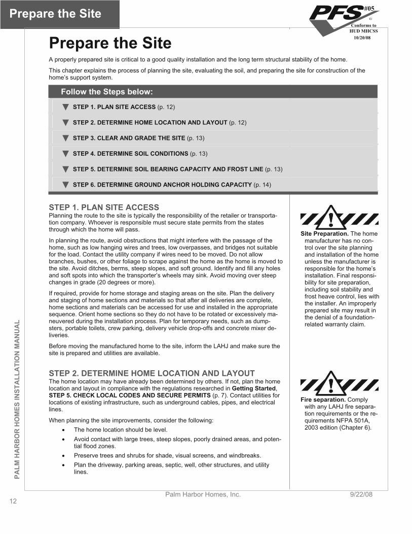
STEP 1. PLAN SITE ACCESS Planning the route to the site is typically the responsibility of the retailer or transporta-tion company. Whoever is responsible must secure state permits from the states through which the home will pass.
Site Preparation. The home manufacturer has no con-trol over the site planning and installation of the home unless the manufacturer is responsible for the home’s installation. Final responsi-bility for site preparation, including soil stability and frost heave control, lies with the installer. An improperly prepared site may result in the denial of a foundation-related warranty claim.
In planning the route, avoid obstructions that might interfere with the passage of the home, such as low hanging wires and trees, low overpasses, and bridges not suitable for the load. Contact the utility company if wires need to be moved. Do not allow branches, bushes, or other foliage to scrape against the home as the home is moved to the site. Avoid ditches, berms, steep slopes, and soft ground. Identify and fill any holes and soft spots into which the transporter’s wheels may sink. Avoid moving over steep changes in grade (20 degrees or more).
If required, provide for home storage and staging areas on the site. Plan the delivery and staging of home sections and materials so that after all deliveries are complete, home sections and materials can be accessed for use and installed in the appropriate sequence. Orient home sections so they do not have to be rotated or excessively ma-neuvered during the installation process. Plan for temporary needs, such as dump-sters, portable toilets, crew parking, delivery vehicle drop-offs and concrete mixer de-liveries.
Before moving the manufactured home to the site, inform the LAHJ and make sure the site is prepared and utilities are available.
STEP 2. DETERMINE HOME LOCATION AND LAYOUT The home location may have already been determined by others. If not, plan the home location and layout in compliance with the regulations researched in Getting Started,STEP 5. CHECK LOCAL CODES AND SECURE PERMITS (p. 7). Contact utilities for locations of existing infrastructure, such as underground cables, pipes, and electrical lines.
When planning the site improvements, consider the following: The home location should be level. Avoid contact with large trees, steep slopes, poorly drained areas, and poten-
tial flood zones. Preserve trees and shrubs for shade, visual screens, and windbreaks. Plan the driveway, parking areas, septic, well, other structures, and utility
lines.
Fire separation. Comply with any LAHJ fire separa-tion requirements or the re-quirements NFPA 501A, 2003 edition (Chapter 6).
#05
Conforms toHUD MHCSS
10/20/08

PALM
HA
RB
OR
HO
MES IN
STALLA
TION
MA
NU
AL
Prepare the Site
9/22/08 Palm Harbor Homes, Inc. 13
Consider future additions, such as screen rooms, porches, and awnings. Site the home away from natural water paths.
STEP 3. CLEAR AND GRADE THE SITE Trim overhanging foliage considering future growth, potential storms, swaying in wind and snow/ice-weighted branches. Remove organic material such as vegetation, wood, roots, twigs, dead branches, grass, and brush from directly under the home. Remove any debris that could become termite infested from the site and surrounding area. Re-move all other debris from the home location, including roots from beneath footing loca-tions. Properly dispose of all items.
Crown the site (Figure 4) away from the foundation for the first ten feet with a minimum slope of 1/2 inch per foot. Where property lines, walls, slopes, or other physical condi-tions prohibit this slope, provide the site with drains, swales, or grading to drain water away from the structure. Any fill required to grade the site should be inorganic “con-trolled fill” applied in a maximum of four inch layers, compacted between each layer to at least 90% of its maximum relative density. Direct runoff away from the site using ditches and berms (Figure 5). If the home will have skirting, start grading from two feet in from the edge of the home.
Site drainage. Moisture un-der the home can result in structural damage to the floor system and other parts of the home. Failure to provide adequate slope/drainage can result in moisture-related problems such as mold, mildew, and erosion.
House
Arrows Indicatedirection of waterflow.
Figure 4. Crown the soil un-der the home to prevent wa-ter ponding
Figure 5. Direct runoff away from the home
Grade the ground so that water under porches, decks, and recessed entries flows away from the home. If proper grading is not possible, use other methods such as a drain tile and automatic sump pump system to remove any water that may collect un-der the home.
The home is suitable for the installation of gutters and downspouts. When gutters and downspouts are installed, direct runoff away from the home.
The home is not suitable for the installation of gutters and downspouts.
STEP 4. DETERMINE SOIL CONDITIONS Examine the soil type under the proposed home location to make sure it is suitable for placement of a home. The design of the home’s support system, including footing/pier spacing and size, will in part be determined by the bearing capacity of the soil, and if ground anchors are used, by the soil’s withdrawal strength.
The soil under every portion of the support system must meet the following criteria: The soil must be firm and undisturbed (not previously excavated) or fill com-
pacted to at least 90% of its maximum relative density. Uncompacted fill will settle over time, causing the home to shift and become unlevel.
Fill must not contain large debris. This too will settle over time. The soil must not be comprised of organic clays or peat. Organic material can
Soil. Inadequate soil bearing capacity or a support sys-tem mismatched to the soil characteristics can result in excessive or differential settlement of the home, which can cause the home to go out of level, resulting in jammed doors and win-
#05
Conforms toHUD MHCSS
10/20/08
Prepare the Site
14Palm Harbor Homes, Inc. 9/22/08
PALM
HA
RB
OR
HO
MES
INST
ALL
ATI
ON
MA
NU
AL
decay, causing settlement, and also may harbor pests that can infest the home.
The water table must be below the lowest level of the planned support sys-tem/foundation. A soil’s bearing capacity can be greatly reduced when it is saturated with water. Note that water tables may vary with seasonal or cli-mactic conditions. Consult a geologist or the LAHJ if you are unsure of the water table level. The soil must not be a highly expansive type. Expansive soils can expand when they become saturated with water, causing the home to shift and be-come unlevel. If soils are expansive, contact a registered engineer, or regis-tered architect to assist with the design of the foundation system.
dows, cracks in finishes and ruptured plumbing connections.
Does the soil meet these criteria? YES, go to STEP 5, DETERMINE SOIL BEARING CAPACITY AND FROST LINE, (p. 14).NO, Consult a registered engineer, registered architect, or geologist to determine a suitable soil bearing capacity.
STEP 5. DETERMINE SOIL-BEARING CAPACITY AND FROST LINE
The soil under a home must be capable of withstanding the loads imposed by the weight of the home, its support system and furnishings, as well as any loads imposed by wind, snow, or other climactic conditions.
SOIL-BEARING CAPACITY Determine the soil-bearing capacity in pounds per square foot (psf) before designing a support system. The higher the capacity (psf), the more weight the soil can hold without unduly compressing. As the soil-bearing capacity increases, footings can be reduced in size or spaced farther apart.
Use one or more of the following methods to determine the site’s soil bearing capacity: Test the soil. Hire a registered geologist, registered engineer, or registered architect to determine the soil classification and maximum allowable soil bear-ing capacity by testing the soil in accordance with generally accepted engi-neering practice. Obtain soil records. The local office of the U.S. Department of Agriculture’s Natural Resources Conservation Service (www.soils.usda.gov) and/or the LAHJ may have test results and/or soil analyses on file for the area. Conduct a pocket penetrometer test. Use a pocket penetrometer to esti-mate allowable soil-bearing capacity as follows: 1. Select a location that will be under a footing. 2. Clear an area of a minimum of one square foot at least four inches deep
or to the depth of the bottom of the planned footing. 3. Using the instructions provided with the pocket penetrometer, take at
least five readings. 4. Discard the high and low readings and average the remaining readings.
Round this result down to the nearest soil-bearing value shown in the right column of Table 4.
5. Confirm that the rounded result matches the soil description on Table 4.Determine soil-bearing value by visual examination. If one of the options above is not available, the values on Table 4 can be used to establish soil-bearing capacity by visual examination. This method provides lower capacity values than the options above. Accurate soil identification typically requires special training or expertise. An engineer or building code official may be able to assist in classifying the soil found on the site.
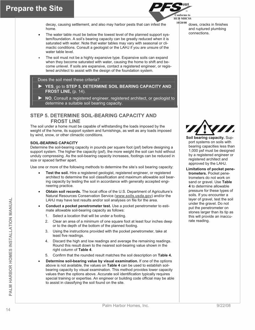
Soil bearing capacity. Sup-port systems on soils with bearing capacities less than 1,000 psf must be designed by a registered engineer or registered architect and approved by the LAHJ.
Limitations of pocket pene-trometers. Pocket pene-trometers do not work on sand or gravel. Use Table 4 to determine allowable pressure for these types of soils. If you encounter a layer of gravel, test the soil under the gravel. Do not put the penetrometer on stones larger than its tip as this will provide an inaccu-rate reading.
#05
Conforms toHUD MHCSS
10/20/08
PALM
HA
RB
OR
HO
MES IN
STALLA
TION
MA
NU
AL
Prepare the Site
9/22/08 Palm Harbor Homes, Inc. 15
TABLE 4. SOIL-BEARING CAPACITY BY SOIL TYPE Soil Type (and classification) Allowable Pressure (psf)
Rock or hard pan (class 1) 4,000
Sandy gravel and gravel; very dense and/or cemented sands; course gravel/cobbles; preloaded silts, clays and coral (class 2) 2,000
Sand; silty sand; clayey sand; silty gravel; medium dense course sands; sandy gravel; very stiff silt, sand clays (class 3) 1,500
Clay, sandy clay, silty clay, clayey silt (classes 4A and 4B) 1,000
Note to table: No allowances made for overburden pressure, embedment depth, water table height, or settlement problems.
Uncompacted fill, peat, organic clays (class 5) Professional testing required
Use default capacity. Use an allowable pressure of 1,500 psf, unless site-specific information requires the use of lower values based on soil classifica-tion and type according to Table 4.
Note that soil types may vary across a home site. In this case, the soil with the lowest bearing capacity should be assumed when designing the support system. Keep a re-cord of the soil-bearing capacity value; it will be used later to design the home’s sup-port system.
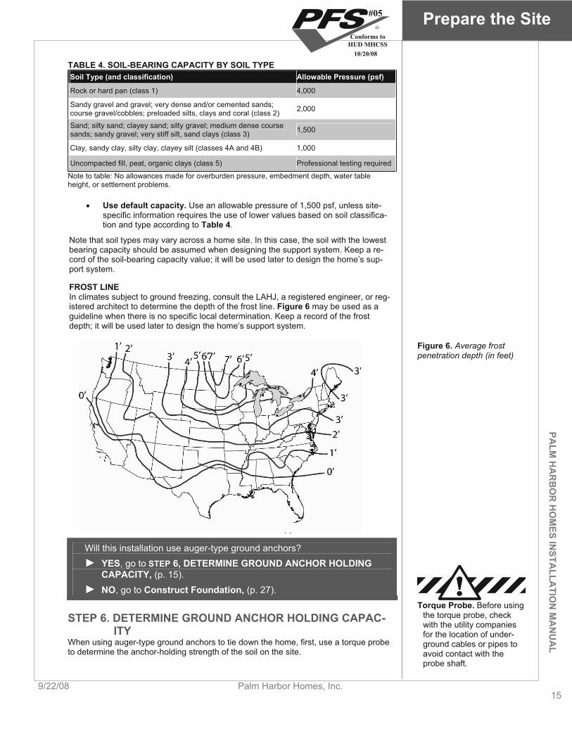
FROST LINE In climates subject to ground freezing, consult the LAHJ, a registered engineer, or reg-istered architect to determine the depth of the frost line. Figure 6 may be used as a guideline when there is no specific local determination. Keep a record of the frost depth; it will be used later to design the home’s support system.
Figure 6. Average frost penetration depth (in feet)
Will this installation use auger-type ground anchors? YES, go to STEP 6, DETERMINE GROUND ANCHOR HOLDING CAPACITY, (p. 15).
NO, go to Construct Foundation, (p. 27).
STEP 6. DETERMINE GROUND ANCHOR HOLDING CAPAC-ITY
When using auger-type ground anchors to tie down the home, first, use a torque probe to determine the anchor-holding strength of the soil on the site.
Torque Probe. Before using the torque probe, check with the utility companies for the location of under-ground cables or pipes to avoid contact with the probe shaft.
#05
Conforms toHUD MHCSS
10/20/08
Prepare the Site
16Palm Harbor Homes, Inc. 9/22/08
PALM
HA
RB
OR
HO
MES
INST
ALL
ATI
ON
MA
NU
AL
Use a torque probe with a shaft of sufficient length to test the soil at the depth of the anchor helical plate. Augur the probe into the ground, and following the probe manufac-turer’s instructions, take the torque wrench reading in the area where the anchors will be installed and at the depth of the anchor helix. If the soil varies in consistency across the site, then use the lowest reading. Based on this reading, consult the anchor manu-facturer’s charts to select the anchor type(s).
What type of support system will this installation use? For pier and ground anchor, go to Install Footings, (p. 17)For load-bearing perimeter wall, go to Construct Foundation, (p. 27)
#05
Conforms toHUD MHCSS
10/20/08
PALM
HA
RB
OR
HO
MES IN
STALLA
TION
MA
NU
AL
Install Footings
9/22/08 Palm Harbor Homes, Inc. 17
Install Footings This chapter provides instructions for the design and construction of individual footings that transfer the load from a single pier to the ground. A footing and pier together (discussed in Set the Home) is referred to as a “support.” A footing may also be designed to carry the load of multiple piers (often called “strip” footings). The design of strip footings is not cov-ered in this manual.
Follow the Steps below:
STEP 1. DESIGN POINT LOAD SUPPORTS (p. 17)
STEP 2. DESIGN FRAME SUPPORTS (Homes Without Perimeter Blocking) (p. 20)
STEP 3. DESIGN FRAME AND PERIMETER SUPPORTS (Homes With Perimeter Blocking) (p.21)
STEP 4. SELECT FOOTING MATERIALS (p. 22)
STEP 5. SIZE FOOTINGS (p. 22)
STEP 6. INSTALL FOOTINGS (p. 25)
STEP 1. DESIGN POINT LOAD SUPPORTS All homes will need supports, and therefore footings, under the frame, marriage line (for multi-section homes), exterior wall openings and other heavy point loads.
The home manufacturer may have provided a blocking diagram (or tags, labels, paint or other markings under the home) indicating the required locations and/or loads for perimeter, marriage line and/or frame supports specifically for this home. If so, the dia-gram or tags take precedence over the directions provided in this manual.
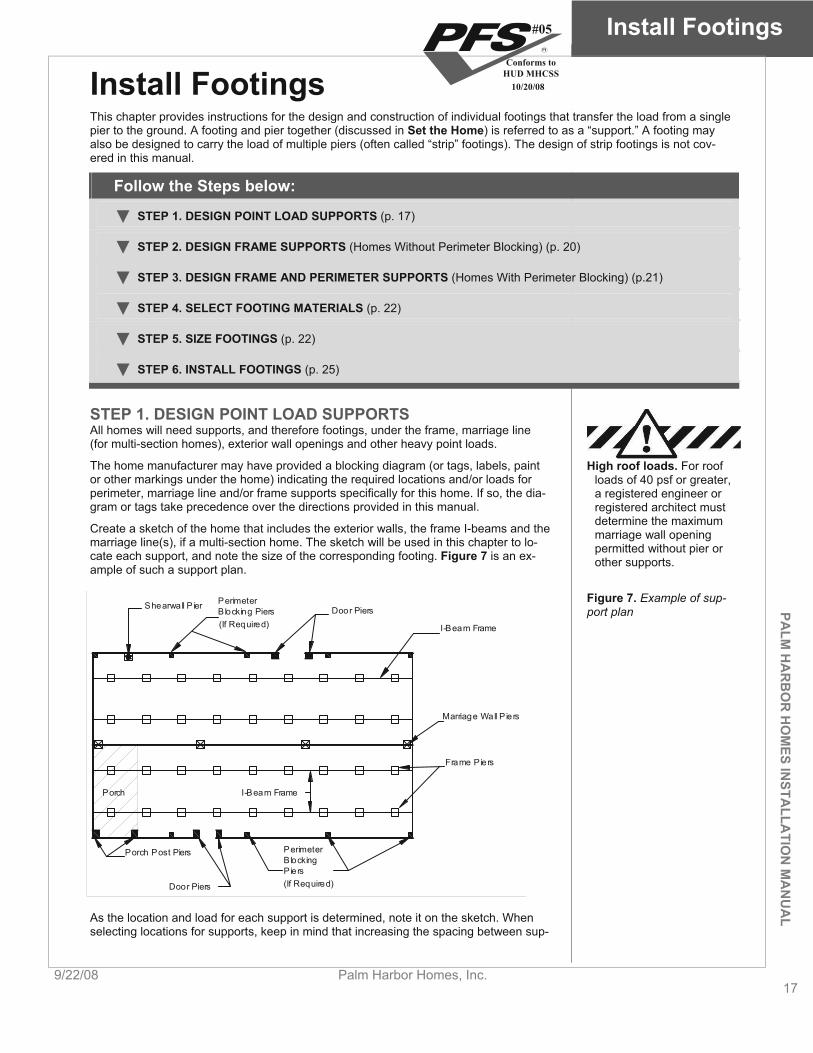
Create a sketch of the home that includes the exterior walls, the frame I-beams and the marriage line(s), if a multi-section home. The sketch will be used in this chapter to lo-cate each support, and note the size of the corresponding footing. Figure 7 is an ex-ample of such a support plan.
High roof loads. For roof loads of 40 psf or greater, a registered engineer or registered architect must determine the maximum marriage wall opening permitted without pier or other supports.
Figure 7. Example of sup-port plan
Door Piers
Shearwall P ier
PerimeterBlocking
Marriage Wall P iers
Door Piers
I-Beam Frame
Frame Piers
Piers
Blocking PiersPerimeter
(If Required)
I-Beam FramePorch
(If Required)
Porch Post Piers
As the location and load for each support is determined, note it on the sketch. When selecting locations for supports, keep in mind that increasing the spacing between sup-
#05
Conforms toHUD MHCSS
10/20/08
Install Footings
18Palm Harbor Homes, Inc. 9/22/08
PALM
HA
RB
OR
HO
MES
INST
ALL
ATI
ON
MA
NU
AL
ports will increase the load on that support and the size of the required footing.
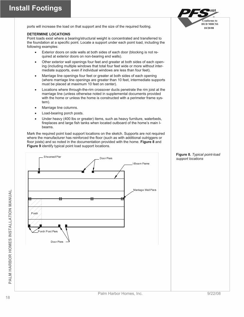
DETERMINE LOCATIONS Point loads exist where a bearing/structural weight is concentrated and transferred to the foundation at a specific point. Locate a support under each point load, including the following examples:
Exterior doors on side walls at both sides of each door (blocking is not re-quired at exterior doors on non-bearing end walls).
Other exterior wall openings four feet and greater at both sides of each open-ing (including multiple windows that total four feet wide or more without inter-mediate supports, even if individual windows are less than four feet).
Marriage line openings four feet or greater at both sides of each opening (where marriage line openings are greater than 10 feet, intermediate supports must be placed at maximum 10 feet on center).
Locations where through-the-rim crossover ducts penetrate the rim joist at the marriage line (unless otherwise noted in supplemental documents provided with the home or unless the home is constructed with a perimeter frame sys-tem).
Marriage line columns. Load-bearing porch posts. Under heavy (400 lbs or greater) items, such as heavy furniture, waterbeds,
fireplaces and large fish tanks when located outboard of the home’s main I-beams.
Mark the required point load support locations on the sketch. Supports are not required where the manufacturer has reinforced the floor (such as with additional outriggers or floor joists) and so noted in the documentation provided with the home. Figure 8 and Figure 9 identify typical point load support locations.
Door Piers
Shearwall P ier
Marriage Wall P iers
Door Piers
I-Beam Frame
Porch
Porch Post Piers
Figure 8. Typical point-load support locations
#05
Conforms toHUD MHCSS
10/20/08

PALM
HA
RB
OR
HO
MES IN
STALLA
TION
MA
NU
AL
Install Footings
9/22/08 Palm Harbor Homes, Inc. 19
Figure 9. Typical point-load support locations along the marriage line
The Installation Manual shipped with the home should include a layout with point load locations and total loads. Use Table 5 only when a model specific layout is not available.
CALCULATE LOADS Use Table 5 to determine the loads on point-load supports. For each support, find the columns with the appropriate roof load zone and section width. Find the row(s) corre-sponding to the span. See Figure 9 for guidance on determining spans. The loads in the “M”-column are for one section only! When support(s) exist on the opposite section in the same location, add the respective loads from each section together to arrive at the total load under that point.
The number in the columns under the “M” and “P” headings are the loads for supports along the marriage line and perimeter respectively (point loads in the center of a sec-tion, i.e. not along a marriage line or perimeter wall, require the load in the “P” column). Interpolation for openings between those shown in the table is permitted.
Note the required loads next to each point load support on the sketch.
TABLE 5. LOAD ON POINT-LOAD FOOTINGS Roof load zone and maximum section width
South (20 psf) Middle (30 psf) North (40 psf) 12 ft 14 ft 16 ft 12 ft 14 ft 16 ft 12 ft 14 ft 16 ft
M P M P M P M P M M P M P M P M PLocation* P4 466 566 546 646 620 720 622 766 868 826 966 777 957 911 1091728 1033 1213
956 1156 1085 1555 1446 1361 17218 816 1016 1285 1089 1369 1275 1726 1594 1954 1808 2168
12 1166 1466 1366 1666 1550 1850 1555 1975 1822 2242 2066 2486 1944 2484 2277 2817 2583 3123
16 1516 1916 1776 2176 2015 2415 2022 2582 2368 2928 2686 3246 2527 3247 2961 3681 3358 4078
20 1866 2366 2186 2686 2480 2980 2489 3189 2915 3615 3306 4006 3111 4011 3644 4544 4133 5033Span
in fe
et
24 2216 2816 2596 3196 2945 3545 2955 3795 3462 4302 3926 4766 3694 4774 4327 5407 4908 5988M = Marriage line, P = Perimeter
Determine from the data plate and/or other documents if the home re-quires perimeter blocking.
If perimeter blocking is NOT required, go to STEP 2, DESIGN FRAME SUPPORTS (Homes Without Perimeter Blocking), (p. 20).If perimeter blocking is required, go to STEP 3, DESIGN FRAME AND PERIMETER SUPPORTS (Homes With Perimeter Blocking),(p. 20).
#05
Conforms toHUD MHCSS
10/20/08

Install Footings
20Palm Harbor Homes, Inc. 9/22/08
PALM
HA
RB
OR
HO
MES
INST
ALL
ATI
ON
MA
NU
AL
STEP 2. DESIGN FRAME SUPPORTS (Homes Without Pe-rimeter Blocking)
DETERMINE LOCATIONS All homes require regularly spaced supports along all main frame I-beams. Select spacing between supports and sketch them on the support plan. Keep in mind that frame supports under homes with 8” deep I-beams may be no more than eight feet apart. Those under homes with 10” or 12” deep I-beams may be no more than 10 feet apart. Generally, greater distances between supports will require larger footings.
Spacing frame supports.There must be a support located near the end of each I-beam such that there is no more than 12 inches of beam past the edge of the support.
Figure 10 shows typical frame support locations.
Figure 10. Typical support locations for homes not re-quiring regularly spaced pe-rimeter supports
CALCULATE LOADS Use Table 6 to determine the loads on frame supports. Find the column with the ap-propriate roof load zone and section width. Find the row corresponding to the selected support spacing. The number in the intersecting cell is the load.
Loads on all frame supports can be assumed to be equal if support spacing is equal. However, if different support spacings are used then each support with a different spacing should be calculated separately.
Note the location and load required of each support on the sketch.
TABLE 6. LOAD ON FRAME SUPPORTS FOR HOMES NOT REQUIRING PERIMETER BLOCKING Roof load zone and max. section width
South (20 psf) Middle (30 psf) North (40 psf) 12 ft 14 ft 16 ft 12 ft 14 ft 16 ft 12 ft 14 ft 16 ft
4 ft 2410 2690 2960 2700 3000 3330
6 ft 3500 3920 4360 3930 4390 4885
8 ft 4600 5155 5740 5170 5780 6440
PERIMETER BLOCKING RE-QUIRED
Max
imum
sup
port
sp
acin
g
Spans shown underlinded apply only when data plate indicates “NO PERIMETER BLOCKING REQUIRED”
go to STEP 4. SELECT FOOTING MATERIALS (p. 22)
#05
Conforms toHUD MHCSS
10/20/08

PALM
HA
RB
OR
HO
MES IN
STALLA
TION
MA
NU
AL
Install Footings
9/22/08 Palm Harbor Homes, Inc. 21
STEP 3. DESIGN FRAME AND PERIMETER SUPPORTS (Homes With Perimeter Blocking)
DETERMINE LOCATIONS Depending on design and location, some homes require regularly spaced perimeter supports along all of the sidewalls and marriage walls in addition to frame supports. This will be indicated on the data plate and/or documents included with the home. Spacing frame supports.
There must be a support located near the end of each I-beam such that there is no more than 12 inches of beam past the edge of the support.
If required, perimeter supports are only needed on bearing walls. Bearing walls are those walls that support the ends of roof trusses or rafters (typically sidewalls and mar-riage walls but not end walls of main units or sidewalls of tag units).
To minimize the number of required perimeter supports, space them evenly between point load supports as shown in Figure 11 and Figure 12 (but not under spans). These figures identify typical support locations for homes requiring perimeter supports.
Perimeter piers are in addition to piers added at column supports and large sidewall openings. In addition, the piers under the columns and sidewall openings must include ½ the load determined for the adjacent perimeter piers. (I.e.: add ½ the load deter-mined from Table 7 to the load determined for the point loads from Table 5)
Figure 11. Typical support locations for homes requiring perimeter supports
Figure 12. Typical marriage line support locations for homes requiring perimeter supports
CALCULATE LOADS Use Table 7 to determine the loads on frame and perimeter supports for homes requir-ing perimeter blocking. Find the column with the appropriate roof load (Table 3) and
#05
Conforms toHUD MHCSS
10/20/08
Install Footings
22Palm Harbor Homes, Inc. 9/22/08
PALM
HA
RB
OR
HO
MES
INST
ALL
ATI
ON
MA
NU
AL
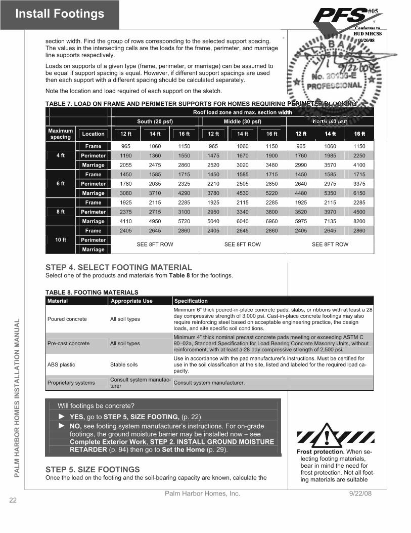
section width. Find the group of rows corresponding to the selected support spacing. The values in the intersecting cells are the loads for the frame, perimeter, and marriage line supports respectively.
Loads on supports of a given type (frame, perimeter, or marriage) can be assumed to be equal if support spacing is equal. However, if different support spacings are used then each support with a different spacing should be calculated separately.
Note the location and load required of each support on the sketch.
TABLE 7. LOAD ON FRAME AND PERIMETER SUPPORTS FOR HOMES REQUIRING PERIMETER BLOCKING Roof load zone and max. section width
South (20 psf) Middle (30 psf) North (40 psf) Maximum spacing Location 12 ft 14 ft 16 ft 12 ft 14 ft 16 ft 12 ft 14 ft 16 ft
Frame 965 1060 1150 965 1060 1150 965 1060 1150
Perimeter 1190 1360 1550 1475 1670 1900 1760 1985 22504 ft
Marriage 2055 2475 2860 2520 3020 3480 2990 3570 4100
Frame 1450 1585 1715 1450 1585 1715 1450 1585 1715
Perimeter 1780 2035 2325 2210 2505 2850 2640 2975 33756 ft
Marriage 3080 3710 4290 3780 4530 5220 4480 5350 6150
Frame 1925 2115 2285 1925 2115 2285 1925 2115 2285
Perimeter 2375 2715 3100 2950 3340 3800 3520 3970 45008 ft
Marriage 4110 4950 5720 5040 6040 6960 5975 7135 8200
Frame 2405 2645 2860 2405 2645 2860 2405 2645 2860
Perimeter10 ft
MarriageSEE 8FT ROW SEE 8FT ROW SEE 8FT ROW
STEP 4. SELECT FOOTING MATERIAL Select one of the products and materials from Table 8 for the footings.
TABLE 8. FOOTING MATERIALS Material Appropriate Use Specification
Poured concrete All soil types
Minimum 6” thick poured-in-place concrete pads, slabs, or ribbons with at least a 28 day compressive strength of 3,000 psi. Cast-in-place concrete footings may also require reinforcing steel based on acceptable engineering practice, the design loads, and site specific soil conditions.
Pre-cast concrete All soil types Minimum 4” thick nominal precast concrete pads meeting or exceeding ASTM C 90–02a, Standard Specification for Load Bearing Concrete Masonry Units, without reinforcement, with at least a 28-day compressive strength of 2,500 psi.
ABS plastic Stable soils Use in accordance with the pad manufacturer’s instructions. Must be certified for use in the soil classification at the site, listed and labeled for the required load ca-pacity.
Proprietary systems Consult system manufac-turer Consult system manufacturer.
Will footings be concrete? YES, go to STEP 5, SIZE FOOTING, (p. 22).NO, see footing system manufacturer’s instructions. For on-grade footings, the ground moisture barrier may be installed now – see Complete Exterior Work, STEP 2. INSTALL GROUND MOISTURE RETARDER (p. 94) then go to Set the Home (p. 29).
STEP 5. SIZE FOOTINGS Once the load on the footing and the soil-bearing capacity are known, calculate the
Frost protection. When se-lecting footing materials, bear in mind the need for frost protection. Not all foot-ing materials are suitable
#05
Conforms toHUD MHCSS
10/20/08

PALM
HA
RB
OR
HO
MES IN
STALLA
TION
MA
NU
AL
Install Footings
9/22/08 Palm Harbor Homes, Inc. 23
size of each footing as follows: 1. From Table 9 determine if the pier is to be of single-stack blocks (8 inch x16
inch) or double-stack blocks (16 inch x 16 inch) pier. 2. Locate the group of rows in Table 10 with the soil-bearing capacity deter-
mined in Prepare the Site, STEP 5. DETERMINE SOIL-BEARING CAPAC-ITY AND FROST LINE (p. 14). Use the next lowest value if the exact value does not appear.
3. Read across the table to determine the minimum required footing area and the minimum footing thickness for the corresponding footing type (single or double-stacked blocks).
4. The required footing size may be changed by selecting another support spac-ing (Table 6 or Table 7).
TABLE 9. PIER CONFIGURATION Pier loca-
tion Height Configuration Maximum load
Less than 36 in (except corner piers more than 3 blocks high)
Single-stack blocks with long side perpendicular to I-beam 8,000 lbs.
Between 36 in and 67 in and cor-ner piers over 3 blocks high Double, interlocked blocks 16,000 lbs. Frame
Over 67 in Double, interlocked blocks 16,000 lbs.
Perimeter 54 in or less Single-stack blocks with long side parallel to perimeter rail (rim joist) 8,000 lbs.
Marriageline 54 in or less Single-stack blocks with long side
perpendicular to the marriage line 8,000 lbs.
for freezing climates.
#05
Conforms toHUD MHCSS
10/20/08
Install Footings
24Palm Harbor Homes, Inc. 9/22/08
PALM
HA
RB
OR
HO
MES
INST
ALL
ATI
ON
MA
NU
AL
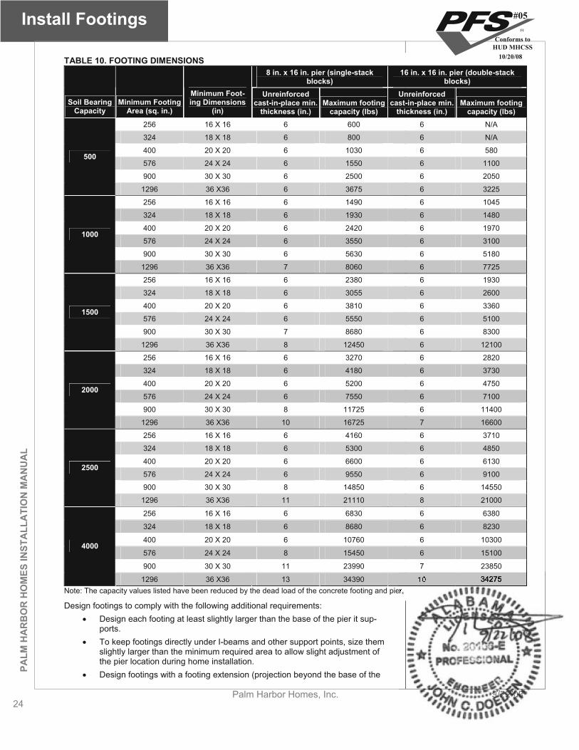
TABLE 10. FOOTING DIMENSIONS 8 in. x 16 in. pier (single-stack
blocks) 16 in. x 16 in. pier (double-stack
blocks)
Soil Bearing Capacity
Minimum Footing Area (sq. in.)
Minimum Foot-ing Dimensions
(in)
Unreinforced cast-in-place min.
thickness (in.) Maximum footing
capacity (lbs)
Unreinforced cast-in-place min.
thickness (in.) Maximum footing
capacity (lbs) 256 16 X 16 6 600 6 N/A
324 18 X 18 6 800 6 N/A
400 20 X 20 6 1030 6 580
576 24 X 24 6 1550 6 1100
900 30 X 30 6 2500 6 2050
500
1296 36 X36 6 3675 6 3225
256 16 X 16 6 1490 6 1045
324 18 X 18 6 1930 6 1480
400 20 X 20 6 2420 6 1970
576 24 X 24 6 3550 6 3100
900 30 X 30 6 5630 6 5180
1000
1296 36 X36 7 8060 6 7725
256 16 X 16 6 2380 6 1930
324 18 X 18 6 3055 6 2600
400 20 X 20 6 3810 6 3360
576 24 X 24 6 5550 6 5100
900 30 X 30 7 8680 6 8300
1500
1296 36 X36 8 12450 6 12100
256 16 X 16 6 3270 6 2820
324 18 X 18 6 4180 6 3730
400 20 X 20 6 5200 6 4750
576 24 X 24 6 7550 6 7100
900 30 X 30 8 11725 6 11400
2000
1296 36 X36 10 16725 7 16600
256 16 X 16 6 4160 6 3710
324 18 X 18 6 5300 6 4850
400 20 X 20 6 6600 6 6130
576 24 X 24 6 9550 6 9100
900 30 X 30 8 14850 6 14550
2500
1296 36 X36 11 21110 8 21000
256 16 X 16 6 6830 6 6380
324 18 X 18 6 8680 6 8230
400 20 X 20 6 10760 6 10300
576 24 X 24 8 15450 6 15100
900 30 X 30 11 23990 7 23850
4000
1296 36 X36 13 34390 10 34275Note: The capacity values listed have been reduced by the dead load of the concrete footing and pier.
Design footings to comply with the following additional requirements: Design each footing at least slightly larger than the base of the pier it sup-
ports. To keep footings directly under I-beams and other support points, size them
slightly larger than the minimum required area to allow slight adjustment of the pier location during home installation.
Design footings with a footing extension (projection beyond the base of the
#05
Conforms toHUD MHCSS
10/20/08
PALM
HA
RB
OR
HO
MES IN
STALLA
TION
MA
NU
AL
Install Footings
9/22/08 Palm Harbor Homes, Inc. 25
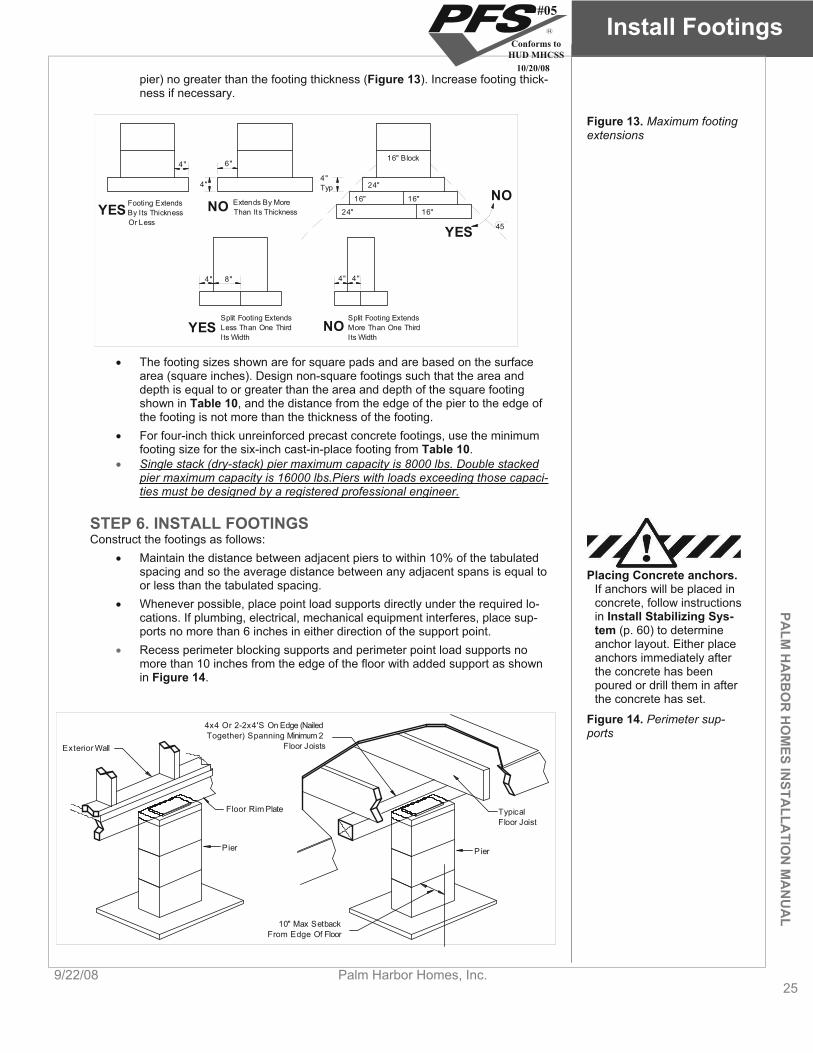
pier) no greater than the footing thickness (Figure 13). Increase footing thick-ness if necessary.
Footing ExtendsBy Its ThicknessOr Less
Extends By MoreThan Its Thickness
Split Footing ExtendsLess Than One ThirdIts Width
Split Footing ExtendsMore Than One ThirdIts Width
NOYES
YES NO
4"4"Typ
6"4"
4" 8" 4" 4"
24"
24"
16" 16"
16"
16" Block
45
NO
YES
Figure 13. Maximum footing extensions
The footing sizes shown are for square pads and are based on the surface area (square inches). Design non-square footings such that the area and depth is equal to or greater than the area and depth of the square footing shown in Table 10, and the distance from the edge of the pier to the edge of the footing is not more than the thickness of the footing.
For four-inch thick unreinforced precast concrete footings, use the minimum footing size for the six-inch cast-in-place footing from Table 10.Single stack (dry-stack) pier maximum capacity is 8000 lbs. Double stacked pier maximum capacity is 16000 lbs.Piers with loads exceeding those capaci-ties must be designed by a registered professional engineer.
STEP 6. INSTALL FOOTINGS Construct the footings as follows:
Maintain the distance between adjacent piers to within 10% of the tabulated spacing and so the average distance between any adjacent spans is equal to or less than the tabulated spacing.
Placing Concrete anchors.If anchors will be placed in concrete, follow instructions in Install Stabilizing Sys-tem (p. 60) to determine anchor layout. Either place anchors immediately after the concrete has been poured or drill them in after the concrete has set.
Whenever possible, place point load supports directly under the required lo-cations. If plumbing, electrical, mechanical equipment interferes, place sup-ports no more than 6 inches in either direction of the support point. Recess perimeter blocking supports and perimeter point load supports no more than 10 inches from the edge of the floor with added support as shown in Figure 14.
Exterior Wall
Floor Rim Plate TypicalFloor Joist
10" Max SetbackFrom Edge Of Floor
4x4 Or 2-2x4'S On Edge (NailedTogether) Spanning Minimum 2
Floor Joists
Pier Pier
Figure 14. Perimeter sup-ports
#05
Conforms toHUD MHCSS
10/20/08
Install Footings
26Palm Harbor Homes, Inc. 9/22/08
PALM
HA
RB
OR
HO
MES
INST
ALL
ATI
ON
MA
NU
AL
If footings are rectangular, orient them so that the long side is perpendicular to the home’s I-beam.
Place the bottom of footings on undisturbed soil or fill compacted to at least 90% of its maximum relative density. Excavation. If
excavation is required, mark the footing locations on the ground with stakes before beginning to dig.
In freezing climates protect footings from the effects of frost heave in accor-dance with any LAHJ requirements (see Prepare the Site, p. 12). Place the bottom of the footings below the frost line (insulated foundations and mono-lithic slabs are other frost protection options not covered in this manual).
Make sure the top surface of the footing is level, flat, and smooth. In accordance with the American Concrete Institute publication ACI-308,
maintain curing measures before construction or installation onto the concrete footing begins, until a minimum of 70% of the specified 28-day compressive strength has been achieved. The ACI recommended time to attain this level of strength is seven days for ASTM C150 Type 1 mixtures and 10 days for Type II mixtures. Full design live and dead loads may not be applied until the 28-day duration has elapsed for achieving full strength.
go to Set the Home (p. 29)
#05
Conforms toHUD MHCSS
10/20/08
PALM
HA
RB
OR
HO
MES IN
STALLA
TION
MA
NU
AL
ConstructFoundation
9/22/08 Palm Harbor Homes, Inc. 27
Construct Foundation (FOR HOMES WITH LOAD-BEARING PERIMETER WALL)
This chapter provides guidelines and recommendations for the design and construction of a basement or crawlspace foundation using a load-bearing perimeter wall. A load-bearing perimeter wall foundation system uses a wall along the outer edge of the home to support the home’s outside walls. This perimeter support works with interior supports such as piers, columns, and cross beams that support the home’s frame and, if multi-section, marriage line.
Follow the Steps below:
STEP 1. OBTAIN A FOUNDATION DESIGN (p. 27)
STEP 2. EXCAVATE (p. 27)
STEP 3. CONSTRUCT THE FOOTING OR SLAB (p. 27)
STEP 4. CONSTRUCT THE PERIMETER WALL (p. 27)
STEP 5. INSTALL INTERIOR SUPPORTS (p. 28)
STEP 6. WATERPROOF FOUNDATION WALL (p. 28)
STEP 7. BACKFILL AND GRADE (p. 28)
STEP 1. OBTAIN A FOUNDATION DESIGN If a load-bearing perimeter wall foundation design has not been provided by the home manufacturer, it is the responsibility of the retailer and/or home owner to provide a de-sign approved by an engineer or architect, licensed in the state where the home will be installed. The approved design must comply with the LAHJ regulations for foundation design, waterproofing, and drainage, and the following:
Using engineered designs.This section is NOT in-tended to provide a com-plete design for a buildable foundation. A complete design must be obtained that is suitable for the local area and sealed by a pro-fessional engineer or regis-tered architect, licensed in the state.
The foundation perimeter bearing wall must be supported with a concrete slab or continuous strip footing around the perimeter of the home. Interior piers must be supported by a slab or footings. If footings are used under interior piers, they may be designed as in Prepare Footings, p. 17.
Slabs must extend to the edges of the home. Footings and slabs must be protected from the effects of frost heave by ex-
tending the footings to or below the frost line or by using a frost protected shallow foundation design.
Foundation ready home.Make sure that homes to be installed on a basement or a crawlspace have been ordered with a recessed frame or as foundation-ready, where the frame is designed to avoid interfer-ence with the foundation wall.
STEP 2. EXCAVATE Excavate for the foundation, properly disposing of the earth that is not needed for backfill or site-grading purposes.
STEP 3. CONSTRUCT THE FOOTINGS OR SLAB Construct the foundation according to the approved design, including the perimeter foundation wall, drainage system, footing(s), and/or slab.
STEP 4. CONSTRUCT THE PERIMETER WALL Checking the water table.For basements, check for a high water table. The water table may vary seasonally or based on weather condi-tions. A geologist can per-form an algae test to de-termine the water table level. The foundation de-sign must account for a
Unless the approved design requires otherwise, construct the perimeter wall with mor-tared and reinforced concrete blocks or reinforced poured-in-place concrete. Install re-inforcement according to the approved design or LAHJ. Install ventilation and access openings according to the approved design, or if not specified, according to the re-quirements in Complete Under the Home, STEP 3 INSTALL SKIRTING (p. 95).
When constructing pockets for an H-beam system, measure the beam depth and lo-cate the pockets carefully. It is critical that when the home’s frame rests on top of the H-beam, the perimeter of the floor rests squarely on the foundation wall sill plate
#05
Conforms toHUD MHCSS
10/20/08
ConstructFoundation
28Palm Harbor Homes, Inc. 9/22/08
PALM
HA
RB
OR
HO
MES
INST
ALL
ATI
ON
MA
NU
AL
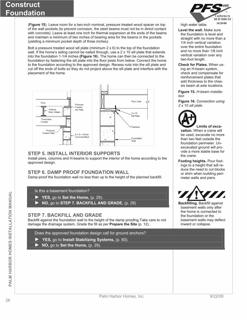
(Figure 15). Leave room for a two-inch nominal, pressure treated wood spacer on top of the wall pockets (to prevent corrosion, the steel beams must not be in direct contact with concrete). Leave at least one inch for thermal expansion at the ends of the beams and maintain a minimum of two inches of bearing area for the beams in the pockets (yielding a minimum pocket depth of three inches).
Bolt a pressure treated wood sill plate (minimum 2 x 6) to the top of the foundation wall. If the home’s siding cannot be nailed through, use a 2 x 10 sill plate that extends into the foundation 1-1/4 inches (Figure 16). The home can then be connected to the foundation by fastening the sill plate into the floor joists from below. Connect the home to the foundation according to the approved design. Recess nuts into the sill plate and cut off the ends of bolts so they do not project above the sill plate and interfere with the placement of the home.
8 x 8 x 16-inchConcrete Block
TransverseH-beam
ChassisMain I-Beam
FloorPressureTreatedSill Plate
PressureTreated Plate
high water table. Level the wall. Make sure
the foundation is level and straight with no more than a 1/4 inch vertical variation over the entire foundation and no more than 1/8 inch vertical variation over any two-foot length.
Check for Plates. When us-ing an H-beam system, check and compensate for reinforcement plates that add thickness to the chas-sis beam at axle locations.
Floor Joist
2 x 10Sill Plate
Fastener
FoundationWall
Figure 15. H-beam installa-tionFigure 16. Connection using 2 x 10 sill plate
Limits of exca-vation. When a crane will be used, excavate no more than two feet outside the foundation perimeter. Un-excavated ground will pro-vide a more stable base for the crane. STEP 5. INSTALL INTERIOR SUPPORTS
Install piers, columns and H-beams to support the interior of the home according to the approved design. Footing heights. Pour foot-
ings to a height that will re-duce the need to cut blocks or shim when building peri-meter walls and piers.
STEP 6. DAMP PROOF FOUNDATION WALL Damp-proof the foundation wall no less than up to the height of the planned backfill.
Is this a basement foundation? YES, go to Set the Home, (p. 29).NO, go to STEP 7. BACKFILL AND GRADE, (p. 28) Backfilling. Backfill against
basement walls only after the home is connected to the foundation or the basement walls may deflect inward or collapse.
STEP 7. BACKFILL AND GRADE Backfill against the foundation wall to the height of the damp proofing.Take care to not damage the drainage system. Grade the fill as per Prepare the Site (p. 12).
Does the approved foundation design call for ground anchors? YES, go to Install Stabilizing Systems, (p. 60).NO, go to Set the Home, (p. 29).
#05
Conforms toHUD MHCSS
10/20/08
PALM
HA
RB
OR
HO
MES IN
STALLA
TION
MA
NU
AL
Set the Home
9/22/08 Palm Harbor Homes, Inc. 29
Set the Home This chapter describes the process of installing the first section of the home (for single section homes this is the only sec-tion) onto the foundation.
Follow the Steps below:
STEP 1. PREPARE FOR SET (p. 29)
STEP 2. POSITION HOME SECTION (p. 29)
STEP 3. LIFT HOME (p. 29)
STEP 4. CONSTRUCT PIERS (p. 31)
STEP 1. PREPARE FOR SET Before beginning the home set, complete the following:
Confirm that the site is properly cleared and graded (see Prepare the Site, p. 12. Clearances under the
home. After the home is leveled, the resulting dis-tance between the bottom of the entire chassis main frame beam and the ground must be no less than 12 inches.
Ensure that the footings are in place and properly located. Install any utilities that will be difficult to install (e.g. those below grade be-
neath the home) after the home is in place. Secure or remove from the home and properly store all ship loose items (refer
to shipping documents for items shipped with the home). Inspect the home interior, exterior and all provided materials, appliances, and
equipment. Immediately report any damage or shortages to the manufacturer. Utilize proper cribbing.Manufactured homes weigh several tons. No one should be under the home (whether it is mov-ing or stationary) unless proper cribbing is in place (Figure 17). Failure to util-ize proper cribbing may result in serious injury or death.
The ground moisture retarder may be installed now or after the home is com-plete. See Complete Exterior Work, STEP 2. INSTALL GROUND MOIS-TURE RETARDER (p. 94) for requirement and then return here.
For perimeter bearing wall foundations: Check that the length and width of the home match with the foundation walls. Check that the two main diagonal measurements of the foundation are equal. Check that the foundation walls and other support points are within 1/4 inch of
level overall and within 1/8 inch of level within any four foot distance. For multi-section homes, check that each pair of diagonal measurements for
each portion of the foundation corresponding to a home section are equal. For multi-section homes, find the electrical bonding lugs on the front or rear
outriggers. Reverse them to the inside of the outrigger using star washers so they will be accessible after the home is placed on the foundation walls.
If using an H-beam system, remove the frame’s shackle hanger if it will inter-fere with proper placement of the beam.
Leveling during jacking. Keep the home’s floor as level as possible during jacking. Twisting or warping the floor can dam-age the structure and finish-ing. Use as many jacks as necessary to keep the floor flat and level.
STEP 2. POSITION HOME SECTION Position the home section in its final location (if possible, move the heaviest section of the home into place first). Then place materials needed to construct support piers near their final locations under the home as determined in Prepare Footings, (p. 17).
STEP 3. LIFT HOME There are three primary methods available to place the home on the foundation: jack-ing, rolling and craning. Jacks, often with roller systems, are typically used for pier and anchor foundations; roller systems are commonly used for crawlspace foundations with load-bearing perimeter walls; and cranes are most commonly used for basement foun-dations.
#05
Conforms toHUD MHCSS
10/20/08
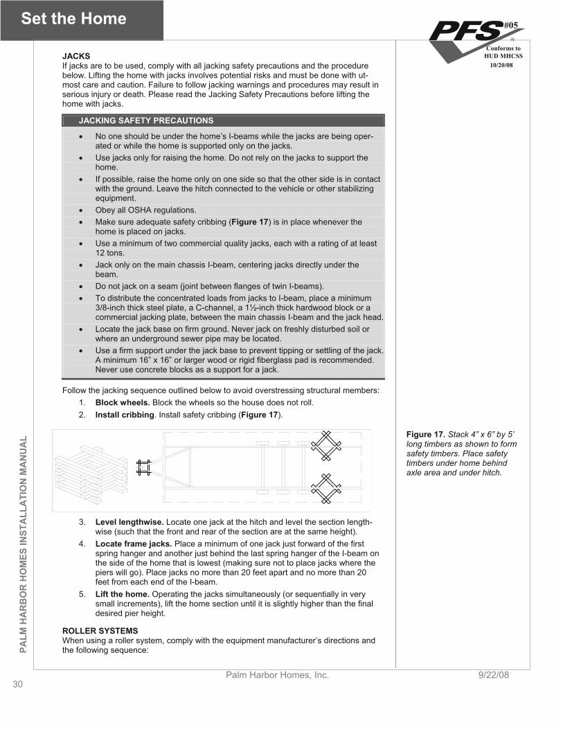
Set the Home
30Palm Harbor Homes, Inc. 9/22/08
PALM
HA
RB
OR
HO
MES
INST
ALL
ATI
ON
MA
NU
AL
JACKS If jacks are to be used, comply with all jacking safety precautions and the procedure below. Lifting the home with jacks involves potential risks and must be done with ut-most care and caution. Failure to follow jacking warnings and procedures may result in serious injury or death. Please read the Jacking Safety Precautions before lifting the home with jacks.
JACKING SAFETY PRECAUTIONS
No one should be under the home’s I-beams while the jacks are being oper-ated or while the home is supported only on the jacks.
Use jacks only for raising the home. Do not rely on the jacks to support the home.
If possible, raise the home only on one side so that the other side is in contact with the ground. Leave the hitch connected to the vehicle or other stabilizing equipment.
Obey all OSHA regulations. Make sure adequate safety cribbing (Figure 17) is in place whenever the
home is placed on jacks. Use a minimum of two commercial quality jacks, each with a rating of at least
12 tons. Jack only on the main chassis I-beam, centering jacks directly under the
beam. Do not jack on a seam (joint between flanges of twin I-beams). To distribute the concentrated loads from jacks to I-beam, place a minimum
3/8-inch thick steel plate, a C-channel, a 1½-inch thick hardwood block or a commercial jacking plate, between the main chassis I-beam and the jack head.
Locate the jack base on firm ground. Never jack on freshly disturbed soil or where an underground sewer pipe may be located.
Use a firm support under the jack base to prevent tipping or settling of the jack. A minimum 16” x 16” or larger wood or rigid fiberglass pad is recommended. Never use concrete blocks as a support for a jack.
Follow the jacking sequence outlined below to avoid overstressing structural members: 1. Block wheels. Block the wheels so the house does not roll. 2. Install cribbing. Install safety cribbing (Figure 17).
Figure 17. Stack 4” x 6” by 5’ long timbers as shown to form safety timbers. Place safety timbers under home behind axle area and under hitch.
3. Level lengthwise. Locate one jack at the hitch and level the section length-wise (such that the front and rear of the section are at the same height).
4. Locate frame jacks. Place a minimum of one jack just forward of the first spring hanger and another just behind the last spring hanger of the I-beam on the side of the home that is lowest (making sure not to place jacks where the piers will go). Place jacks no more than 20 feet apart and no more than 20 feet from each end of the I-beam.
5. Lift the home. Operating the jacks simultaneously (or sequentially in very small increments), lift the home section until it is slightly higher than the final desired pier height.
ROLLER SYSTEMS When using a roller system, comply with the equipment manufacturer’s directions and the following sequence:
#05
Conforms toHUD MHCSS
10/20/08

PALM
HA
RB
OR
HO
MES IN
STALLA
TION
MA
NU
AL
Set the Home
9/22/08 Palm Harbor Homes, Inc. 31
1. Establish staging area. Establish a staging area directly adjacent to one or both sides of the foundation.
2. Setup rollers. Set up the roller system according to the equipment manufac-turer’s directions.
3. Fasten bump blocks. Temporarily fasten wooden bump blocks on the sill plates at the ends of the foundation to stop the home from rolling at the de-sired location.
4. Roll home. Roll the home into place over the foundation. 5. Remove bump blocks. Remove the blocks before installing the next section
of a multi-section home.
CRANES When using a crane, follow these guidelines:
Position the home section(s) and crane (taking the boom reach into consid-eration) such that they do not have to be repositioned during the set.
Use enough properly sized straps to maintain balance of the home and to prevent damage to the structure.
Place straps under walls or posts, including temporary posts used to support the opening. Do not position lifting straps under marriage wall openings.
Use a properly sized spreader bar to maintain a vertical lift, to avoid placing compression forces on the eaves and to reduce any tendency to slip.
Connect a rope to at least one point on the home so it can be controlled while aloft.
Make provisions to retrieve the straps/cables after the home is set. If using a cradle system, notch the sill plate where the straps will fall. For a sling sys-tem, notch and reinforce the home’s rim joist to keep the strap from slipping and allow the strap to be removed after the home is set.
Always set the home section farthest from the crane first so that subsequent section(s) need not be lifted over previously set sections.
Have the interior foundation supports already been designed and installed as part of an approved load-bearing perimeter wall foundation?
YES, go to Complete Multi-Section Set, (p. 35) or go to Connect Utilities, (p. 75) for single section homes. NO, go to STEP 4. INSTALL PIERS, (p. 31).
STEP 4. CONSTRUCT PIERS For the side of the home section that is up on jacks, place piers on footings or pads fol-lowing the home manufacturer’s blocking plan (or tags). If no plan was provided, use the support plan developed in Install Footings (p. 17). Start at one end of the home section and work toward the other noting the required pier material specifications and procedure described below.
Designing piers. Incorrect size, location or spacing of piers may result in serious structural damage to the home. Install piers at all re-quired locations. Failure to do so may lead to sagging floors, walls, and roofs, and could void the home’s war-ranty.
Construct piers so as to provide a stable foundation for the home using materials listed in the specifications box below and based on the location of the pier and its height as measured from the top of the footing or pad to the top of the cap. See Table 12 for pier construction requirements.
#05
Conforms toHUD MHCSS
10/20/08

Set the Home
32Palm Harbor Homes, Inc. 9/22/08
PALM
HA
RB
OR
HO
MES
INST
ALL
ATI
ON
MA
NU
AL
TABLE 11. PIER MATERIAL MINIMUM SPECIFICATIONS Component Specification
Concrete Block Nominal dimensions of at least 8” x 8” x 16”; minimum load 8,000 lbs; confirming to ASTM designation C90, grade N.
CapsSolid masonry (nominal 4” x 8” x 16” pre-cast concrete without reinforcement); pressure treated lumber (nominal 2” x 8” x 16”); or steel (minimum 1/2” thick, corrosion protected by a min. of a 10 mil coating of an exterior paint or equivalent).
Spacers Nominal 2” thick boards.
Shims (also called wedges)
Hardwood, minimum 4” width by minimum 6” length by maximum 1” thick (nominal); plastic must be listed with maximum load capacity; used in pairs.
Commercial metal or pre-cast concrete piers
Available in various sizes stamped with maximum load capacity and listed or labeled for the required verti-cal load capacity, and where required by design, for the appropriate horizontal load capacity. Metal or other manufactured piers must be provided with protection against weather deterioration and corrosion at least equivalent to that provided by a coating of zinc on steel of .30 oz per sq. ft of surface coated.
Pressure treated wood With a water borne preservative, in accordance with AWPA Standard U1–04 for Use Category 4B ground contact applications.
TABLE 12. PIER CONSTRUCTION
Pier location Height Configuration Maximum offset top to bottom Maximum load Mortar and reinforce-
ment Less than 36 in (except corner piers more than 3 blocks high)
Single-stack blocks with long side perpendicular to I-beam ½” 8,000 lbs. Not required
Between 36 in and 67 in and corner piers over 3 blocks high
Double, interlocked blocks 1” (½” up to 36” high) 16,000 lbs. Not required
Frame
Over 67 in Designed by a registered engineer or registered architect
Perimeter 54 in or less* Single-stack blocks with long side parallel to perimeter rail (rim joist)
½” up to 36” high, 1” over 36” high 8,000 lbs. Not required
Marriage line 54 in or less* Single-stack blocks with long side perpendicular to the marriage line
½” up to 36” high, 1” over 36” high 8,000 lbs. Not required
* Construct perimeter and marriage line piers over 54 inches according to the requirements for frame piers of the same height.
1. Prepare footing surface. Make sure the footing surface upon which the pier sits is flat and smooth. Before placing the pier on the footing, clean dirt, rocks, or other material off the surface of the footing. For cast-in-place concrete foot-ings, if the footing surface is uneven, create a level, flat surface by placing a treated board on the footing and mortaring on the first block (or manufactured pier base), or by placing the first block (or manufactured pier base) on a layer of premix dry sand mortar.
2. Stack blocks. Stack concrete blocks with their hollow cells aligned vertically. When piers are constructed of blocks stacked side-by-side, orient each layer at right angles to the previous one (Figure 18) and plan blocks so that split caps will be perpendicular to the blocks they rest on and to the I-beam.
#05
Conforms toHUD MHCSS
10/20/08

PALM
HA
RB
OR
HO
MES IN
STALLA
TION
MA
NU
AL
Set the Home
9/22/08 Palm Harbor Homes, Inc. 33
Main I-Beam
Optional 2x6Spacer
4x8x16 ConcreteCap or 2x8x16 P.T.or Hardwood Cap
Typical 8x8x16Concrete Block
Typical Footing
Wood Shims to FillGaps Up to 1" Max
Less
Tha
n 36
"
Main I-BeamWood Shims to FillGaps Up to 1' Max
Optional (2) 2x6 or(1) 2x12 Spacer
4x8x16 Concrete Cap
Typical Footing
Typical 8x8x16Concrete Block
36" t
o 67
"
Figure 18. Frame pier con-struction
3. Cap piers. Place a cap on hollow block piers to evenly distribute the structural load. Use caps the same length and width as the piers they rest upon. When using split caps on double-stacked block piers, install the caps with the long dimension perpendicular to the joint in the blocks below and to the main I-beam. Curing time of mortar.
Where wet mortar is used to construct or level piers, al-low it to cure to at least 80% of strength capacity (usually requiring 96 hours) before setting the home.
4. Install shims. Use shims to level the home and fill any gaps between the base of the I-beam and the top of the pier cap. Always use shims in pairs (Figure 19). Drive them in tightly so they do not occupy more than one inch of vertical space. When the space to be shimmed is greater than one inch and less than the minimum thickness of available caps or concrete blocks, use hardwood dimensional lumber (two inches maximum thickness) or 2” or 4” thick concrete block. For split caps, install shims and dimensional lum-ber/blocks over each individual cap.
Figure 19. Correct shim placementI-Beam
Shims
Spacer
Cap
Dimensions of masonry perimeter walls.If using a masonry perimeter enclosure, calculate pier heights so that the enclo-sure can be built using stan-dard unit dimensions (with-out cutting).
5. Set up level. Set up a water level with the fluid level at the desired height of the main piers. Carefully lower the side of the section down onto the leveled piers, adjusting the final height with shims.
USING A WATER LEVEL A water level is a standard device for leveling the home. The level consists of the following components: One container (five gallon bucket or one gallon jug).
Level the home. The home is adequately leveled if there is 150 feet of 1/2 inch diameter plastic tubing.
#05
Conforms toHUD MHCSS
10/20/08
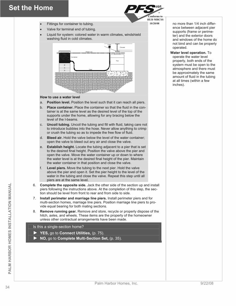
Set the Home
34Palm Harbor Homes, Inc. 9/22/08
PALM
HA
RB
OR
HO
MES
INST
ALL
ATI
ON
MA
NU
AL
Fittings for container to tubing. Valve for terminal end of tubing. Liquid for system: colored water in warm climates, windshield
washing fluid in cold climates.
Water Line
Valve
Chassis
Pier
Tube
Conta iner
no more than 1/4 inch differ-ence between adjacent pier supports (frame or perime-ter) and the exterior doors and windows of the home do not bind and can be properly operated.
Water level operation. To operate the water level properly, both ends of the system must be open to the atmosphere and there must be approximately the same amount of fluid in the tubing at all times (within a few inches).
How to use a water level a. Position level. Position the level such that it can reach all piers. b. Place container. Place the container so that the fluid in the con-
tainer is at the same level as the desired level of the top of the supports under the home, allowing for any bracing below the level of the I-beams.
c. Uncoil tubing. Uncoil the tubing and fill with fluid, taking care not to introduce bubbles into the hose. Never allow anything to crimp or crush the tubing so as to impede the free flow of fluid.
d. Bleed air. Hold the valve below the level of the water container; open the valve to bleed out any air and close the valve.
e. Establish height. Locate the tubing adjacent to a pier that is set to the desired final height. Position the valve above the pier and open the valve. Move the water container up or down to where the water level is at the desired final height of the pier. Maintain the water container in that position and close the valve.
f. Level piers. Move the tubing to the next pier. Hold the valve above the pier and open it. Set the pier height to the level of the water in the tubing and close the valve. Repeat this step until all piers are at the same level.
6. Complete the opposite side. Jack the other side of the section up and install piers following the instructions above. At the completion of this step, the sec-tion should be level from front to rear and from side to side.
7. Install perimeter and marriage line piers. Install perimeter piers and for multi-section homes, marriage line piers. Position marriage line piers to pro-vide equal bearing for both mating sections.
8. Remove running gear. Remove and store, recycle or properly dispose of the hitch, axles, and wheels. These items are the property of the homeowner unless other contractual arrangements have been made.
Is this a single-section home? YES, go to Connect Utilities, (p. 75).NO, go to Complete Multi-Section Set, (p. 35).
#05
Conforms toHUD MHCSS
10/20/08
PALM
HA
RB
OR
HO
MES IN
STALLA
TION
MA
NU
AL
Complete Multi- Section Set
9/22/08 Palm Harbor Homes, Inc. 35
Complete Multi-Section Set This chapter covers the preparation and installation of additional home sections, including the structural connections be-tween units, raising and fastening hinged roofs, and fastening the home to a load-bearing perimeter wall foundation.
Follow the Steps below:
STEP 1. INSTALL MARRIAGE LINE ANCHORS (p. 35)
STEP 2. REMOVE PROTECTIVE SHIPPING MATERIALS (p. 35)
STEP 3. COMPLETE HINGED ROOF (p. 35)
STEP 4. REPAIR OR INSTALL MARRIAGE LINE GASKET (p. 35)
STEP 5. POSITION ADDITIONAL HOME SECTIONS (p. 36)
STEP 6. CONNECT FLOORS (p. 37)
STEP 7. CONNECT ROOF (p. 38)
STEP 8. CONNECT WALLS (p. 40)
STEP 9. ATTACH TAG UNITS (p. 41)
STEP 10. REMOVE TEMPORARY ITEMS (p. 42)
STEP 11. FASTEN HOME TO FOUNDATION (p. 42)
STEP 12. BACKFILL AND GRADE (p. 42)
STEP 13. BUILD STAIRS (p. 42)
STEP 1. INSTALL MARRIAGE LINE ANCHORS If the home is in Wind Zone II or III, install ground anchors along the marriage line now; before mating sections are joined see Install Stabilizing System (p. 60). After install-ing marriage line anchors return to this point in Complete Multi-Section Set.
Position roof jacks. Posi-tion jacks vertically to pre-vent the jack foot from kick-ing out or sliding.
STEP 2. REMOVE PROTECTIVE SHIPPING MATERIALS Remove all shipping protection and associated fasteners from both home sections to be joined, including plastic used to close up the open sides during transportation. Do not remove the temporary supports holding up the ceilings at major openings.
Caution during roof rais-ing. Do not enter the roof cavity during the raising procedure. STEP 3. COMPLETE HINGED ROOF
Checklists for alternate construction. If the serial number (see the data plate or the chassis front cross member) has the letters “AC” before or after it, then the Alternate Construction on-site check list supplied with the home must be completed and returned to the home manufacturer in a timely manner. If the AC checklist relates to the roof,
If the home has a hinged roof that has been folded down for shipping, raise the roof us-ing a crane or roof jacks following the procedure below. Note: Due to the variety of hinged roof designs, Palm Harbor Homes, Inc. includes model specific instructions with each home that includes a hinged roof design, including fastening and special installa-tion instructions. ALWAYS refer to the model specific instructions for connections.
1. Position lift points. Position the roof lift points (jacks or crane lift points) fol-lowing the jack manufacturer or crane operator instructions. Space roof lift points equally along the length of the roof with no more than five feet from the end of the roof to the first or last lift points. Use three lift points for a roof up to 48 feet long (excluding overhangs), four lift points for up to 60 feet, and five lift points for up to 72 feet.
2. Remove fasteners. Remove any temporary fasteners connecting the hinged
#05
Conforms toHUD MHCSS
10/20/08
Complete Multi- Section Set
36Palm Harbor Homes, Inc. 9/22/08
PALM
HA
RB
OR
HO
MES
INST
ALL
ATI
ON
MA
NU
AL
portion of the roof to the vertical king posts. then failure to do so may require future disassembly of the roof and further in-spections.
3. Lift roof. Raise the roof to its intended height. A temporary slight overexten-sion may be required during lifting. However, take care not to overextend the roof and damage the hinge. Raise the roof evenly in small increments, keep-ing it level throughout the entire process to prevent racking. Do not allow roof-ing paper and shingles to get caught in the hinge crease.
4. Secure king posts. Position the hinged king posts (may be a knee wall) atop the fixed king posts or against the wooden stop. The king posts are either hinged to the underside of the hinged-truss top chord or shipped loose as a knee wall stored in the roof cavity. Position them as needed to level the roof, aligning each king post with the king post directly beneath it, and securing it in place, following the model specific instructions as applicable.
5. Unfold double hinge. If the roof has a double hinge top chord, unfold and secure the second hinge per the model specific instructions.
6. Fasten sheathing. Fasten sheathing from the upper portion of the roof to the lower fixed portion of the roof just below hinges per the model specific instruc-tions as applicable.
7. Redistribute Insulation. Before closing up the attic space check that the in-sulation has not shifted. Re-level the insulation if needed.
8. Install gable walls. Assembled frames or wall studs and sheathing needed for the site assembly of the gable end walls and interior shear wall knee walls (if present) may be provided. Install the gable end walls for each home section per the model specific instructions.
9. Install vents. Extend plumbing vents, exhaust fans, appliance vents, and fire-place stacks through the hinged portion of the roof in strict accordance with this manual (Prepare Appliances and Equipment, p. 84) and/or supplemen-tal instructions provided by the home manufacturer.
STEP 4. REPAIR OR INSTALL MARRIAGE LINE GASKET A continuous, non-porous gasket creating a permanent air barrier must be installed on at least one side of the marriage line; along the floor, end walls and ceiling (and mar-riage lines for any tag units). The manufacturer has provided a marriage line gasket ei-ther installed on the home or shipped loose. If installed, inspect the gasket and repair any gaps or tears.
Checking through-the-rim-ducts. Ensure that through-the-rim-duct connections are secure and tight after the home sections are to-gether.
If not installed at the factory, install a continuous gasket between the home sections along the floor, end walls, and ceiling.
STEP 5. POSITION ADDITIONAL HOME SECTIONS Follow this procedure to install additional home sections:
1. Remove obstructions. Remove protruding nails and staples or anything else that will keep the home sections from fitting together snugly. If present, cut the temporary ceiling and floor plates at the edges of marriage line openings tak-ing care not to damage ceiling or floor coverings or displace temporary mar-riage line support posts (these supports and the plates will be removed after the home sections have been structurally connected).
Mechanical po-sitioning system. For a pier-set home, a mechani-cal positioning system (such as a roller system) will make the process eas-ier and safer and be less likely to damage the home.
2. Complete crossovers. Before moving the two sections together, complete any crossover connections that require access from the open marriage line, including the attic duct connection (if present) and marriage wall interior elec-trical connections (see Connect Crossovers, p.48).
3. Position section. Position the section as closely as possible (ideally within six inches) and line up with the previously set section. If using a mechanical positioning system or crane, follow the system manufacturer’s instructions or the crane operator’s directions.
Sealing gaps. Prior to com-pletion of the exterior close-up, gaps that do not exceed
4. Construct piers. With the outside walls of the home aligned, construct the piers for the home section according to the instructions in Set the Home (p. 29) before continuing to the steps below.
#05
Conforms toHUD MHCSS
10/20/08
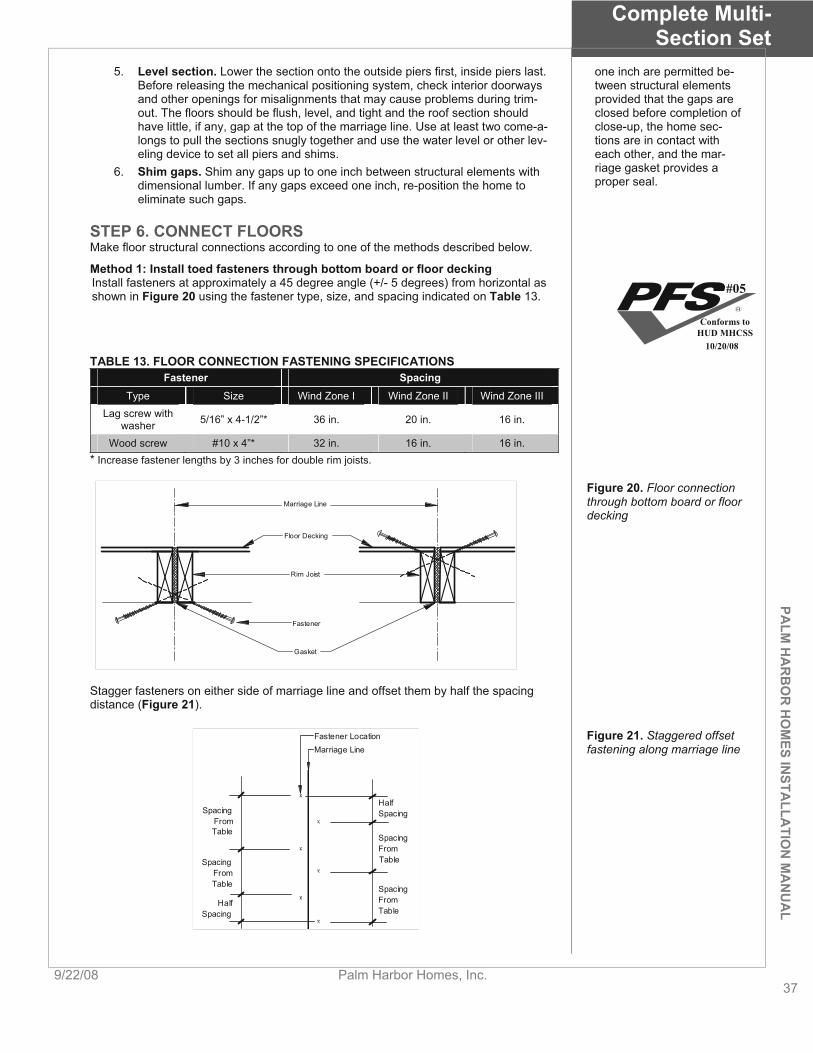
PALM
HA
RB
OR
HO
MES IN
STALLA
TION
MA
NU
AL
Complete Multi- Section Set
9/22/08 Palm Harbor Homes, Inc. 37
5. Level section. Lower the section onto the outside piers first, inside piers last. Before releasing the mechanical positioning system, check interior doorways and other openings for misalignments that may cause problems during trim-out. The floors should be flush, level, and tight and the roof section should have little, if any, gap at the top of the marriage line. Use at least two come-a-longs to pull the sections snugly together and use the water level or other lev-eling device to set all piers and shims.
one inch are permitted be-tween structural elements provided that the gaps are closed before completion of close-up, the home sec-tions are in contact with each other, and the mar-riage gasket provides a proper seal.
6. Shim gaps. Shim any gaps up to one inch between structural elements with dimensional lumber. If any gaps exceed one inch, re-position the home to eliminate such gaps.
STEP 6. CONNECT FLOORS Make floor structural connections according to one of the methods described below.
Method 1: Install toed fasteners through bottom board or floor decking Install fasteners at approximately a 45 degree angle (+/- 5 degrees) from horizontal as shown in Figure 20 using the fastener type, size, and spacing indicated on Table 13.
TABLE 13. FLOOR CONNECTION FASTENING SPECIFICATIONS Fastener Spacing
Type Size Wind Zone I Wind Zone II Wind Zone III Lag screw with
washer 5/16” x 4-1/2”* 36 in. 20 in. 16 in.
Wood screw #10 x 4”* 32 in. 16 in. 16 in. * Increase fastener lengths by 3 inches for double rim joists.
Figure 20. Floor connection through bottom board or floor decking
Marriage Line
Floor Decking
Rim Joist
Gasket
Fastener
Stagger fasteners on either side of marriage line and offset them by half the spacing distance (Figure 21).
Fastener LocationMarriage Line
HalfSpacing
HalfSpacing
SpacingFromTable
SpacingFromTable
SpacingFromTable
SpacingFromTable
Figure 21. Staggered offset fastening along marriage line
#05
Conforms toHUD MHCSS
10/20/08

Complete Multi- Section Set
38Palm Harbor Homes, Inc. 9/22/08
PALM
HA
RB
OR
HO
MES
INST
ALL
ATI
ON
MA
NU
AL
n Wind Zones II and III, fasten metal straps of minimum 26 gauge, 1-1/2” wide galvanized steel spaced per Table 14 and fastened per Table 15 to the un-derside of the floor joists (Figure 22). Select a strap length sufficient to hold the required fasteners. Straps are not required in Wind Zone I.
TABLE 14 MAXIMUM STRAP SPACING Roof slope Wind Zone II Wind Zone III
Up to 4-in-12 96 in. 80 in. Over 4-in-12 48 in. 48 in.
TABLE 15. STRAP FASTENING MINIMUM SPECIFICATIONS Fastener type Size Number
Galvanized staples 16ga 7/16” x 1” penetration 12 each side Roofing nails 1-1/2” long 9 each side
See ChartFor Spacing
FloorJoist
MetalStrap
MarriageLine
Patch bottom board. Use adhesive spray, mastic, and/or diver-gent staples in combination with bottom board tape for a more secure and durable connection.
Figure 22. Metal strapping for Wind Zones II and III
Floor Joist
Metal Strap
Rim Joist
FloorDecking
Marriage Line
Nails
STEP 7. CONNECT ROOF If the marriage line along the roof is not snug, position jacks every 20 feet or less along the outside I-beam and uniformly lift the section until the roof area is tight.
Check to make sure the ceiling joint is flush before installing the connections. If not, use a jack and tee to raise whichever ceiling is low, starting at the front and working to the rear of the home. Fasten the roof along the marriage line using one of the methods below for either double or triple-section homes.
Closing the roof gap. Level and fasten the marriage line joint at the floor before jacking to tighten a roof gap. DO NOT use roof fas-teners to close any gaps. Separation of the ridge beams and trusses may occur.
DOUBLE-SECTION HOMES Method 1: Install toed fasteners through roof sheathing Install the fasteners through the roof deck into the ridge beams at an approximately 45 degree angle (+/- 5 degrees) from horizontal (Figure 23) according to the fastener spacing and specifications in Table 16. Stagger fasteners on each side of marriage line and offset them by half the spacing distance (Figure 21). Spacing indicated is on-center, both sides of ridge. Make sure fasteners penetrate the ridge beam/rail by a minimum of 1-1/2 inches both sides of ridge.
Fasteners
RoofSheathing
Ridge Beam
Approx.45
Figure 23. Toed fasteners through roof sheathing
TABLE 16. ROOF CONNECTIONS SPECIFICATIONS
#05
Conforms toHUD MHCSS
10/20/08
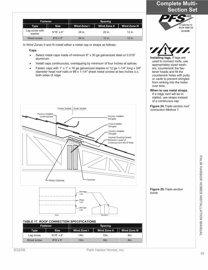
PALM
HA
RB
OR
HO
MES IN
STALLA
TION
MA
NU
AL
Complete Multi- Section Set
9/22/08 Palm Harbor Homes, Inc. 39
Fastener Spacing Type Size Wind Zone I Wind Zone II Wind Zone III
Lag screw with washer 5/16” x 6” 28 in. 20 in. 12 in.
Wood screw #10 x 5” 24 in. 12 in. 12 in.
In Wind Zones II and III install either a metal cap or straps as follows:
Caps Select metal caps made of minimum 8" x 30 ga galvanized steel or 0.019”
aluminum. Install caps continuously, overlapping by minimum of four inches at splices. Fasten caps with 1” x 1” x 16 ga galvanized staples or 12 ga 1-1/4” long x 3/8”
diameter head roof nails or #8 x 1-1/4" sheet metal screws at two inches o.c. both sides of ridge.
Installing lags. If lags are used to connect roofs, use appropriately sized wash-ers, countersink the fas-tener heads and fill the countersink holes with putty or caulk to prevent shingles from sinking into the holes over time.
When to use metal straps.If a ridge vent will be in-stalled, use straps instead of a continuous cap.
Figure 24.Triple-section roof connection Method 1
Factory-InstalledShingles
Field-InstalledShingles
Factory-InstalledShingles
Factory-InstalledUnderlayment
Asphalt Roofing CementBetween Layers ofUnderlayment Min 6" Wide
Metal (Optional)
Outer SectionCenter Section
Fastener
MarriageLine
RidgeLine
MarriageLine
Plan Elevation
Figure 25.Triple-sectionhome
TABLE 17. ROOF CONNECTION SPECIFICATIONS Fastener Spacing
Type Size Wind Zone I Wind Zone II Wind Zone III
Lag screw 5/16” x 6” 14in. 10in. 6in.
Wood screw #10 x 5” 12in. 6in. 6in.
#05
Conforms toHUD MHCSS
10/20/08

Complete Multi- Section Set
40Palm Harbor Homes, Inc. 9/22/08
PALM
HA
RB
OR
HO
MES
INST
ALL
ATI
ON
MA
NU
AL
Method 2: Install fasteners with ship loose sheathing For homes where sheathing is shipped loose to be installed on site (Figure 26) fasten field-installed sheathing to all underlying blocking and framing with 15 ga 7/16” x 1-1/2” staples at four inches o.c. in field and perimeter.
Factory-InstalledUnderlayment
Asphalt Roofing CementBetween Layers ofUnderlaymentMin. 6" Wide.
Factory-InstalledShingles
Factory-InstalledShingles
Field-InstalledShingles
Factory-Installed Nailer
Factory-Installed Sheathing
Field-InstalledSheathing
Field-InstalledUnderlayment
Figure 26.Triple-section roof connection Method 2
STEP 8. CONNECT WALLS Once the home is secured along the marriage line floor and roof, secure end walls, in-terior doorways, and marriage line partitions according to the appropriate method de-scribed below.
END WALLS Method 1: Install toed fasteners through sheathing Toe fasteners through sheathing from the exterior at an approximately 45 degree angle (+/- 5 degrees) (Figure 27) according to the fastener specifications and spacing re-quirements in Table 18.
GasketWall Studs
Exterior Sidingor Exterior
SidingUnderlayment
Fastener
Figure 27. End wall connec-tion toed through sheathing
TABLE 18. END WALL FASTENER SPECIFICATIONS Fastener type Size Spacing
Lag screw with washer 5/16” x 5” 12in. o.c. Wood screw #8 x 3” 8in. o.c.
Nail 16d 8in. o.c.
TABLE 19. MARRIAGE WALL CONNECTION SPECIFICATIONS Fastener type Size Spacing Wood screw #8 x 4” 16 in. o.c.
#05
Conforms toHUD MHCSS
10/20/08
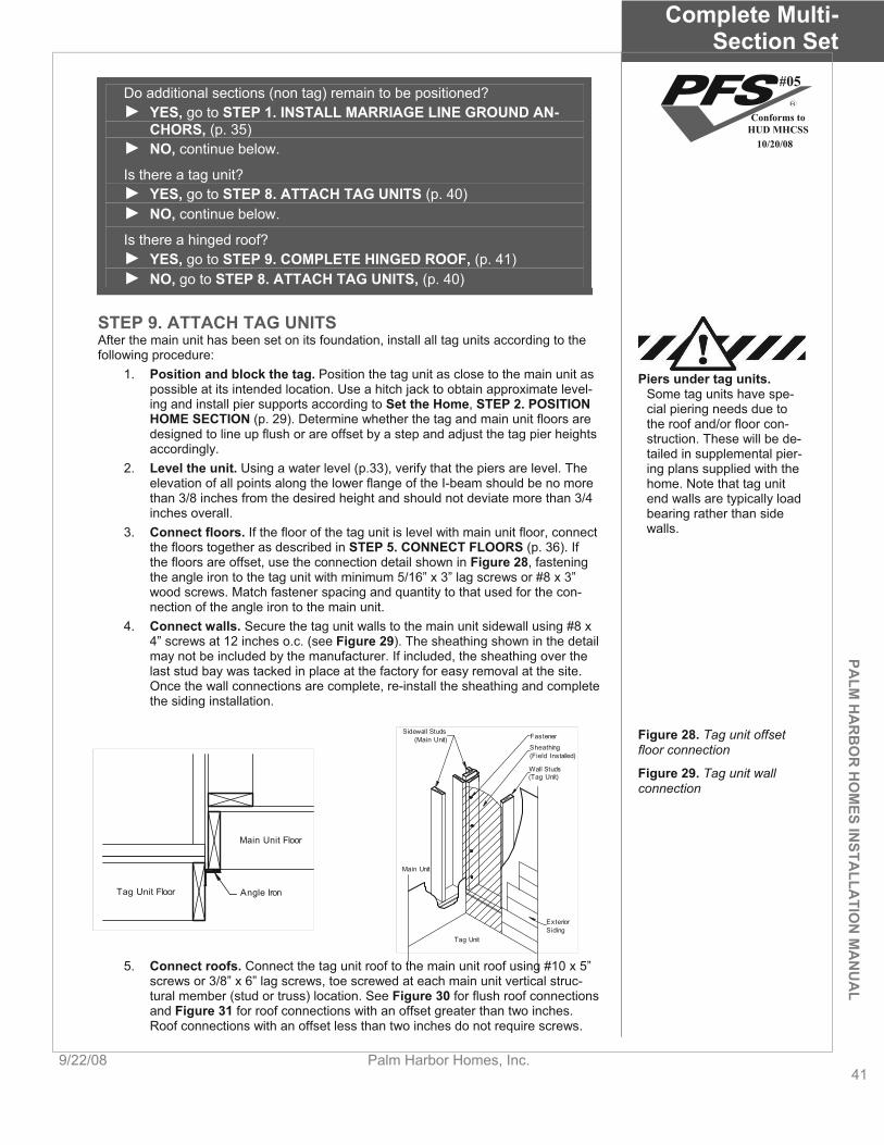
PALM
HA
RB
OR
HO
MES IN
STALLA
TION
MA
NU
AL
Complete Multi- Section Set
9/22/08 Palm Harbor Homes, Inc. 41
Do additional sections (non tag) remain to be positioned? YES, go to STEP 1. INSTALL MARRIAGE LINE GROUND AN-CHORS, (p. 35)NO, continue below.
Is there a tag unit? YES, go to STEP 8. ATTACH TAG UNITS (p. 40)NO, continue below.
Is there a hinged roof? YES, go to STEP 9. COMPLETE HINGED ROOF, (p. 41)NO, go to STEP 8. ATTACH TAG UNITS, (p. 40)
STEP 9. ATTACH TAG UNITS After the main unit has been set on its foundation, install all tag units according to the following procedure:
1. Position and block the tag. Position the tag unit as close to the main unit as possible at its intended location. Use a hitch jack to obtain approximate level-ing and install pier supports according to Set the Home, STEP 2. POSITION HOME SECTION (p. 29). Determine whether the tag and main unit floors are designed to line up flush or are offset by a step and adjust the tag pier heights accordingly.
Piers under tag units.Some tag units have spe-cial piering needs due to the roof and/or floor con-struction. These will be de-tailed in supplemental pier-ing plans supplied with the home. Note that tag unit end walls are typically load bearing rather than side walls.
2. Level the unit. Using a water level (p.33), verify that the piers are level. The elevation of all points along the lower flange of the I-beam should be no more than 3/8 inches from the desired height and should not deviate more than 3/4 inches overall.
3. Connect floors. If the floor of the tag unit is level with main unit floor, connect the floors together as described in STEP 5. CONNECT FLOORS (p. 36). If the floors are offset, use the connection detail shown in Figure 28, fastening the angle iron to the tag unit with minimum 5/16” x 3” lag screws or #8 x 3” wood screws. Match fastener spacing and quantity to that used for the con-nection of the angle iron to the main unit.
4. Connect walls. Secure the tag unit walls to the main unit sidewall using #8 x 4” screws at 12 inches o.c. (see Figure 29). The sheathing shown in the detail may not be included by the manufacturer. If included, the sheathing over the last stud bay was tacked in place at the factory for easy removal at the site. Once the wall connections are complete, re-install the sheathing and complete the siding installation.
Angle IronTag Unit Floor
Main Unit Floor
ExteriorSiding
Tag Unit
Sidewall Studs(Main Unit) Fastener
Sheathing(Field Installed)
Wall Studs(Tag Unit)
Main Unit
Figure 28. Tag unit offset floor connection
Figure 29. Tag unit wall connection
5. Connect roofs. Connect the tag unit roof to the main unit roof using #10 x 5” screws or 3/8” x 6” lag screws, toe screwed at each main unit vertical struc-tural member (stud or truss) location. See Figure 30 for flush roof connections and Figure 31 for roof connections with an offset greater than two inches. Roof connections with an offset less than two inches do not require screws.
#05
Conforms toHUD MHCSS
10/20/08
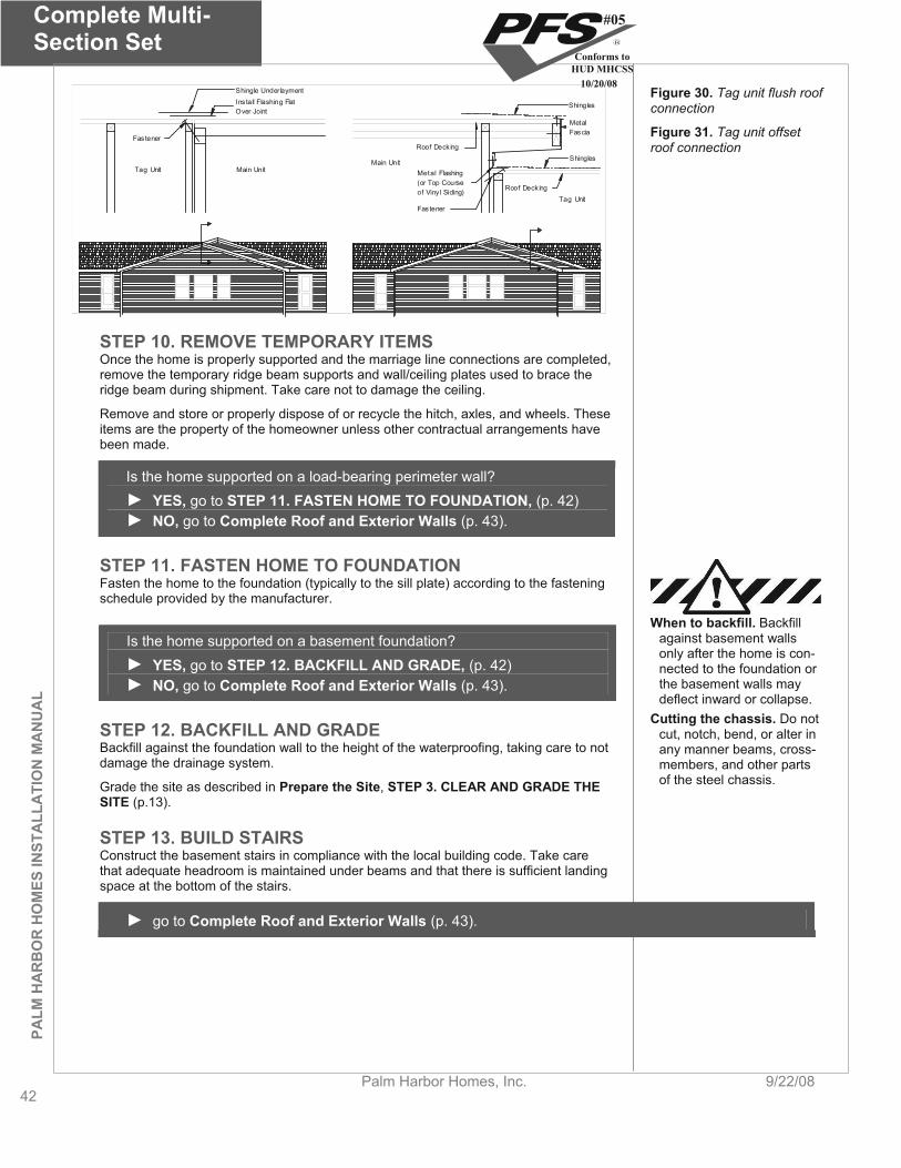
Complete Multi- Section Set
42Palm Harbor Homes, Inc. 9/22/08
PALM
HA
RB
OR
HO
MES
INST
ALL
ATI
ON
MA
NU
AL
Metal Flashing(or Top Courseof Viny l Siding)
Roof Deck ing
Roof Deck ing
Shingles
MetalFascia
Shingles
Main Unit
Tag UnitFas tener
Tag Unit Main Unit
Ins tall Flashing FlatOver Joint
Shingle Underlayment
Fas tener
Figure 30. Tag unit flush roof connection
Figure 31. Tag unit offset roof connection
STEP 10. REMOVE TEMPORARY ITEMS Once the home is properly supported and the marriage line connections are completed, remove the temporary ridge beam supports and wall/ceiling plates used to brace the ridge beam during shipment. Take care not to damage the ceiling.
Remove and store or properly dispose of or recycle the hitch, axles, and wheels. These items are the property of the homeowner unless other contractual arrangements have been made.
Is the home supported on a load-bearing perimeter wall? YES, go to STEP 11. FASTEN HOME TO FOUNDATION, (p. 42)
NO, go to Complete Roof and Exterior Walls (p. 43).
STEP 11. FASTEN HOME TO FOUNDATION Fasten the home to the foundation (typically to the sill plate) according to the fastening schedule provided by the manufacturer.
When to backfill. Backfill against basement walls only after the home is con-nected to the foundation or the basement walls may deflect inward or collapse.
Is the home supported on a basement foundation? YES, go to STEP 12. BACKFILL AND GRADE, (p. 42)
NO, go to Complete Roof and Exterior Walls (p. 43).
Cutting the chassis. Do not cut, notch, bend, or alter in any manner beams, cross-members, and other parts of the steel chassis.
STEP 12. BACKFILL AND GRADE Backfill against the foundation wall to the height of the waterproofing, taking care to not damage the drainage system.
Grade the site as described in Prepare the Site, STEP 3. CLEAR AND GRADE THE SITE (p.13).
STEP 13. BUILD STAIRS Construct the basement stairs in compliance with the local building code. Take care that adequate headroom is maintained under beams and that there is sufficient landing space at the bottom of the stairs.
go to Complete Roof and Exterior Walls (p. 43).
#05
Conforms toHUD MHCSS
10/20/08
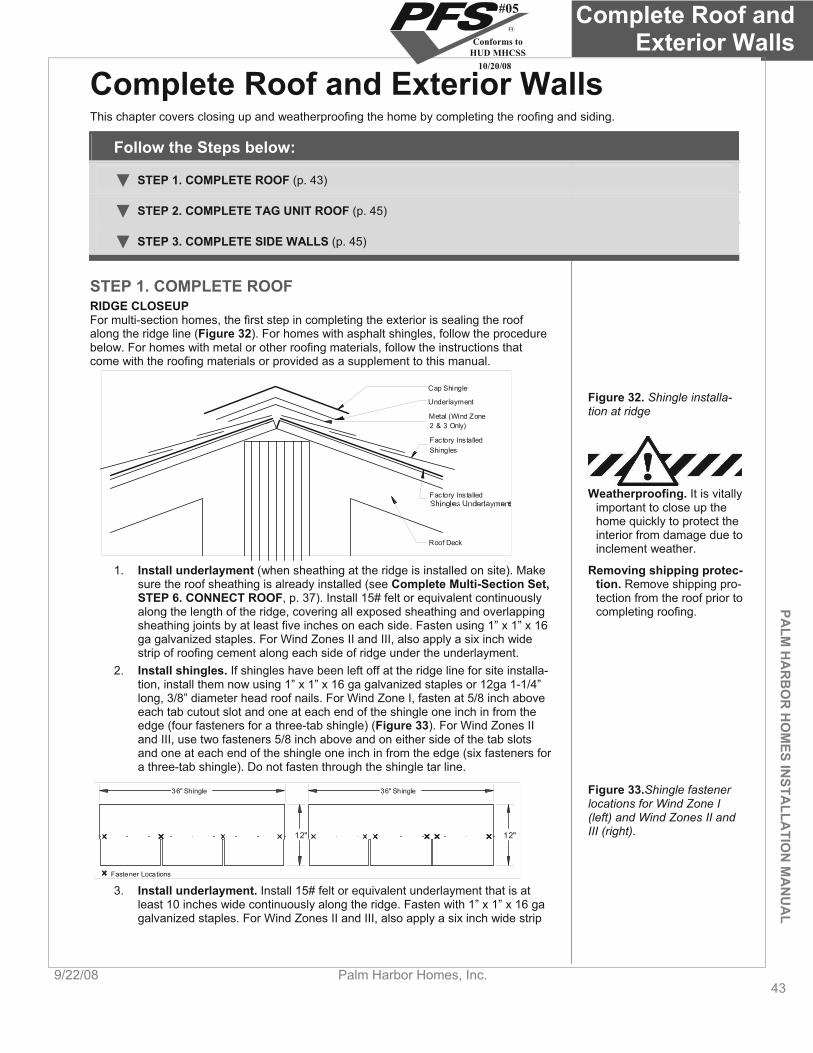
PALM
HA
RB
OR
HO
MES IN
STALLA
TION
MA
NU
AL
Complete Roof and Exterior Walls
9/22/08 Palm Harbor Homes, Inc. 43
Complete Roof and Exterior Walls This chapter covers closing up and weatherproofing the home by completing the roofing and siding.
Follow the Steps below:
STEP 1. COMPLETE ROOF (p. 43)
STEP 2. COMPLETE TAG UNIT ROOF (p. 45)
STEP 3. COMPLETE SIDE WALLS (p. 45)
STEP 1. COMPLETE ROOF RIDGE CLOSEUP For multi-section homes, the first step in completing the exterior is sealing the roof along the ridge line (Figure 32). For homes with asphalt shingles, follow the procedure below. For homes with metal or other roofing materials, follow the instructions that come with the roofing materials or provided as a supplement to this manual.
Roof Deck
Factory InstalledShingles
Metal (Wind Zone2 & 3 Only)
Underlayment
Cap Shingle
Factory Installed
Figure 32. Shingle installa-tion at ridge
Weatherproofing. It is vitally important to close up the home quickly to protect the interior from damage due to inclement weather.
1. Install underlayment (when sheathing at the ridge is installed on site). Make sure the roof sheathing is already installed (see Complete Multi-Section Set,STEP 6. CONNECT ROOF, p. 37). Install 15# felt or equivalent continuously along the length of the ridge, covering all exposed sheathing and overlapping sheathing joints by at least five inches on each side. Fasten using 1” x 1” x 16 ga galvanized staples. For Wind Zones II and III, also apply a six inch wide strip of roofing cement along each side of ridge under the underlayment.
Removing shipping protec-tion. Remove shipping pro-tection from the roof prior to completing roofing.
2. Install shingles. If shingles have been left off at the ridge line for site installa-tion, install them now using 1” x 1” x 16 ga galvanized staples or 12ga 1-1/4” long, 3/8” diameter head roof nails. For Wind Zone I, fasten at 5/8 inch above each tab cutout slot and one at each end of the shingle one inch in from the edge (four fasteners for a three-tab shingle) (Figure 33). For Wind Zones II and III, use two fasteners 5/8 inch above and on either side of the tab slots and one at each end of the shingle one inch in from the edge (six fasteners for a three-tab shingle). Do not fasten through the shingle tar line.
36" Shingle
12"
36" Shingle
12"
Fastener Locations
Figure 33.Shingle fastener locations for Wind Zone I (left) and Wind Zones II and III (right).
3. Install underlayment. Install 15# felt or equivalent underlayment that is at least 10 inches wide continuously along the ridge. Fasten with 1” x 1” x 16 ga galvanized staples. For Wind Zones II and III, also apply a six inch wide strip
#05
Conforms toHUD MHCSS
10/20/08
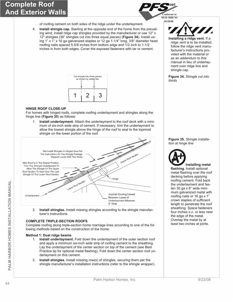
Complete RoofAnd Exterior Walls
44Palm Harbor Homes, Inc. 9/22/08
PALM
HA
RB
OR
HO
MES
INST
ALL
ATI
ON
MA
NU
AL
of roofing cement on both sides of the ridge under the underlayment. 4. Install shingle cap. Starting at the opposite end of the home from the prevail-
ing wind, install ridge cap shingles provided by the manufacturer or use 12" x 12" shingles (36” shingles cut into three equal pieces) (Figure 34). Install us-ing 1” x 1” x 16 ga galvanized staples or 12 ga 1-1/4” long, 3/8” diameter head roofing nails spaced 5-5/8 inches from bottom edge and 1/2 inch to 1-1/2 inches in from both edges. Cover the exposed fasteners with tar or cement.
Installing a ridge vent. If a ridge vent is to be installed, follow the ridge vent manu-facturer’s instructions pro-vided with the material or as an addendum to this manual in lieu of underlay-ment over ridge line and shingle cap.
as shown by dotted line
1 2 3
Figure 34. Shingle cut into thirds
HINGE ROOF CLOSE-UP For homes with hinged roofs, complete roofing underlayment and shingles along the hinge line (Figure 35) as follows:
1. Install underlayment. Attach the underlayment to the roof deck with a mini-mum of six-inch wide strip of cement. If necessary, trim the underlayment to allow the lowest shingle above the hinge of the roof to seal to the topmost shingle on the lower portion of the roof.
Hinge
Upper Roof Section
Lower Roof Section
Underlayment
After Roof Is In The Raised Position,Trim The Shingle Underlayment To
Allow The Shingle Of The UpperRoof Section To Seal Onto The LastShingle Of The Lower Roof Section.
Site Install Shingles In Hinged Area PerThe Instructions On The Shingle Package
Shipped Loose With The Home.
Asphalt Roofing CementBetween Layers ofUnderlayment Minumum6" Wide
Figure 35. Shingle installa-tion at hinge line
Installing metal flashing. Install optional metal flashing over the roof decking before applying roofing cement. Fold back the underlayment and fas-ten 30 ga x 6” wide mini-mum galvanized metal with roofing nails or 16 ga x 1” crown staples of sufficient length to penetrate the roof sheathing. Space fasteners four inches o.c. or less near the edge of the metal. Overlap the metal by at least two inches at joints.
2. Install shingles. Install missing shingles according to the shingle manufac-turer’s instructions.
COMPLETE TRIPLE-SECTION ROOFS Complete roofing along triple-section home marriage lines according to one of the fol-lowing methods based on the construction of the home.
Method 1: Dual ridge beams 1. Install underlayment. Fold down the underlayment of the outer section roof
and apply a minimum six-inch wide strip of roofing cement to the sheathing. Lay the underlayment of the center section on top of the cement (see Best Practice tip for optional metal flashing). Fold down the center section roof un-derlayment on this cement.
2. Install shingles. Install missing row(s) of shingles, securing them per the shingle manufacturer’s installation instructions (refer to the shingle wrapper).
#05
Conforms toHUD MHCSS
10/20/08

PALM
HA
RB
OR
HO
MES IN
STALLA
TION
MA
NU
AL
Complete Roof and Exterior Walls
9/22/08 Palm Harbor Homes, Inc. 45
Factory-InstalledShingles
Field-InstalledShingles
Factory-InstalledShingles
Factory-InstalledUnderlayment
Asphalt Roofing CementBetween Layers ofUnderlayment Min 6" Wide
Metal (Optional)
Outer SectionCenter Section
Fastener
Figure 36. Triple-section roof connection Method 1
Method 2: Field-installed sheathing 1. Install underlayment. Fold down the underlayment of the outer section roof
and fold up the underlayment on the center section roof. Apply to the lower roof underlayment a minimum six-inch wide strip of roofing cement centered on the sheathing joint. Cover with the shipped loose underlayment. Apply an-other minimum six-inch wide strip of roofing cement to the ship loose under-layment centered on the upper roof sheathing joint.
2. Install shingles. Install missing row(s) of shingles per the shingle manufac-turer’s installation instructions (refer to the shingle wrapper).
Factory-InstalledUnderlayment
Figure 37. Triple-section roof connection Method 2Factory-Installed
Shingles
Asphalt Roofing CementBetween Layers ofUnderlaymentMin. 6" Wide.
Factory-InstalledShingles
Field-InstalledShingles
Factory-Installed Nailer
Field-InstalledUnderlayment
Field-InstalledSheathing
Factory-Installed Sheathing
STEP 2. COMPLETE TAG UNIT ROOF If the home has a tag unit, complete roofing for this unit now. The process for complet-ing the roof is different for flush and offset roofs. Follow the instructions in the appropri-ate section below.
FLUSH ROOFS For flush roofs, complete roofing along the marriage line and at the valley line as fol-lows (see Figure 38):
#05
Conforms toHUD MHCSS
10/20/08
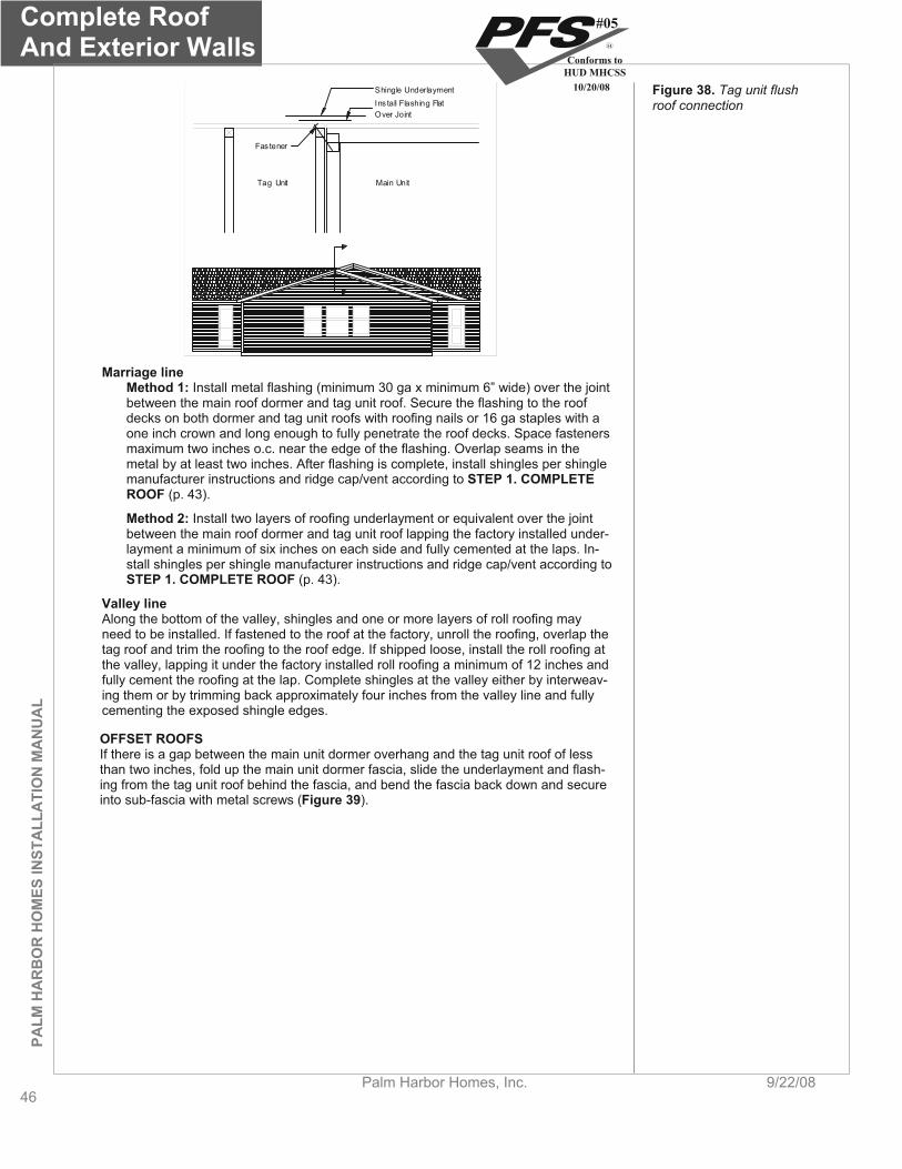
Complete RoofAnd Exterior Walls
46Palm Harbor Homes, Inc. 9/22/08
PALM
HA
RB
OR
HO
MES
INST
ALL
ATI
ON
MA
NU
AL
Tag Unit Main Unit
Ins tall Flashing FlatOver Joint
Shingle Underlayment
Fas tener
Figure 38. Tag unit flush roof connection
Marriage line Method 1: Install metal flashing (minimum 30 ga x minimum 6” wide) over the joint between the main roof dormer and tag unit roof. Secure the flashing to the roof decks on both dormer and tag unit roofs with roofing nails or 16 ga staples with a one inch crown and long enough to fully penetrate the roof decks. Space fasteners maximum two inches o.c. near the edge of the flashing. Overlap seams in the metal by at least two inches. After flashing is complete, install shingles per shingle manufacturer instructions and ridge cap/vent according to STEP 1. COMPLETE ROOF (p. 43).
Method 2: Install two layers of roofing underlayment or equivalent over the joint between the main roof dormer and tag unit roof lapping the factory installed under-layment a minimum of six inches on each side and fully cemented at the laps. In-stall shingles per shingle manufacturer instructions and ridge cap/vent according to STEP 1. COMPLETE ROOF (p. 43).
Valley line Along the bottom of the valley, shingles and one or more layers of roll roofing may need to be installed. If fastened to the roof at the factory, unroll the roofing, overlap the tag roof and trim the roofing to the roof edge. If shipped loose, install the roll roofing at the valley, lapping it under the factory installed roll roofing a minimum of 12 inches and fully cement the roofing at the lap. Complete shingles at the valley either by interweav-ing them or by trimming back approximately four inches from the valley line and fully cementing the exposed shingle edges.
OFFSET ROOFSIf there is a gap between the main unit dormer overhang and the tag unit roof of less than two inches, fold up the main unit dormer fascia, slide the underlayment and flash-ing from the tag unit roof behind the fascia, and bend the fascia back down and secure into sub-fascia with metal screws (Figure 39).
#05
Conforms toHUD MHCSS
10/20/08
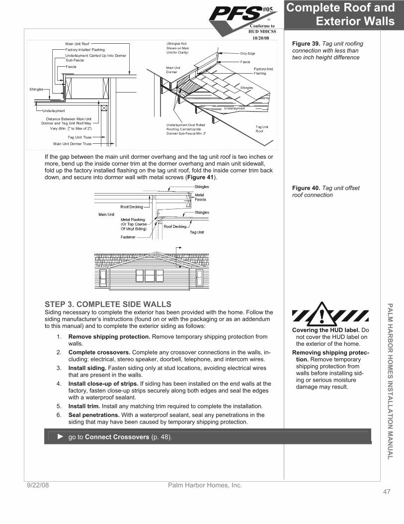
PALM
HA
RB
OR
HO
MES IN
STALLA
TION
MA
NU
AL
Complete Roof and Exterior Walls
9/22/08 Palm Harbor Homes, Inc. 47
(Shingles NotShown on MainUnit for Clarity) Drip Edge
Fascia
Flashing
Shingles
Underlayment
Tag UnitRoof
Underlayment Over RolledRoofing Carried Up IntoDormer Sub-Fascia Min. 3"
Main UnitDormer
Fascia
Underlayment Carried Up Into DormerSub-Fascia
Factory-Intalled Flashing
Shingles
Underlayment
Tag Unit Truss
Distance Between Main UnitDormer and Tag Unit Roof May
Vary (Min. 14" to Max of 2")
Main Unit Dormer Truss
Main Unit Roof Figure 39. Tag unit roofing connection with less than two inch height difference
If the gap between the main unit dormer overhang and the tag unit roof is two inches or more, bend up the inside corner trim at the dormer overhang and main unit sidewall, fold up the factory installed flashing on the tag unit roof, fold the inside corner trim back down, and secure into dormer wall with metal screws (Figure 41).
Figure 40. Tag unit offset roof connection
STEP 3. COMPLETE SIDE WALLS Siding necessary to complete the exterior has been provided with the home. Follow the siding manufacturer’s instructions (found on or with the packaging or as an addendum to this manual) and to complete the exterior siding as follows:
Covering the HUD label. Do not cover the HUD label on the exterior of the home.
1. Remove shipping protection. Remove temporary shipping protection from walls.
2. Complete crossovers. Complete any crossover connections in the walls, in-cluding: electrical, stereo speaker, doorbell, telephone, and intercom wires.
Removing shipping protec-tion. Remove temporary shipping protection from walls before installing sid-ing or serious moisture damage may result.
3. Install siding. Fasten siding only at stud locations, avoiding electrical wires that are present in the walls.
4. Install close-up of strips. If siding has been installed on the end walls at the factory, fasten close-up strips securely along both edges and seal the edges with a waterproof sealant.
5. Install trim. Install any matching trim required to complete the installation. 6. Seal penetrations. With a waterproof sealant, seal any penetrations in the
siding that may have been caused by temporary shipping protection.
go to Connect Crossovers (p. 48).
#05
Conforms toHUD MHCSS
10/20/08

ConnectCrossovers
48Palm Harbor Homes, Inc. 9/22/08
PALM
HA
RB
OR
HO
MES
INST
ALL
ATI
ON
MA
NU
AL
Connect Crossovers This chapter covers crossover connections between units of multi-section homes, including ducts and electrical, water, waste, gas, telephone, and cable TV connections.
Follow the Steps below:
STEP 1. CONNECT DUCTS (p. 48)
STEP 2. CONNECT ELECTRICAL CROSSOVERS (p. 50)
STEP 3. INSTALL ELECTRICAL BONDING (p. 53)
STEP 4. CONNECT WATER LINES (p. 53)
STEP 5. CONNECT DRAIN, WASTE, AND VENT LINES (p. 54)
STEP 6. CONNECT GAS LINES (p. 56)
STEP 7. CONNECT TELEPHONE AND CABLE TV WIRING (p. 57)
STEP 1. CONNECT DUCTS There are three main types of duct crossover connections. Based on the location of the duct, follow the installation steps on the page indicated below:
Under the floor (p. 48). Qualified personnel. Use only qualified personnel to make crossover connec-tions. Consult the LAHJ for licensing or any additional crossover connection re-quirements.
In the roof cavity (p. 50). In floor, through-the-rim joist (p. 50)
To prevent air leakage, seal all ductwork connections, including duct collars using one or more of the following materials:
Galvanized metal straps in combination with galvanized sheet metal screws. Access for service. When-
ever possible maintain ac-cess to connection areas for future maintenance.
For rigid air ducts and connectors, tape and mastics listed to UL 181A. For flexible air ducts and connectors, tape and mastics listed to UL 181B.
UNDER FLOOR FLEXIBLE CROSSOVER DUCT Make tight connections.
Permanent, durable, and tight crossover duct con-nections are critical to the proper performance of the home. Leaky ducts can re-sult in severe moisture problems in the home, dis-comfort from rooms not re-ceiving the proper amount of conditioned air, and high utility bills from wasted heating and/or cooling en-ergy.
When heating or cooling equipment is installed in the home, the flexible crossover duct is provided by the manufacturer. In all cases the crossover duct must be listed for exte-rior use.
There are four common configurations of under floor crossover ducts depending on the number of home sections and the furnace/air handler location. See Table 20 to locate the appropriate figure.
TABLE 20. UNDER FLOOR DUCT CONFIGURATIONS Furnace location Two home sections Three home sections
Furnace over trunk duct See Figure 41 See Figure 43
Furnace offset from trunk duct See Figure 42 See Figure 44
#05
Conforms toHUD MHCSS
10/20/08
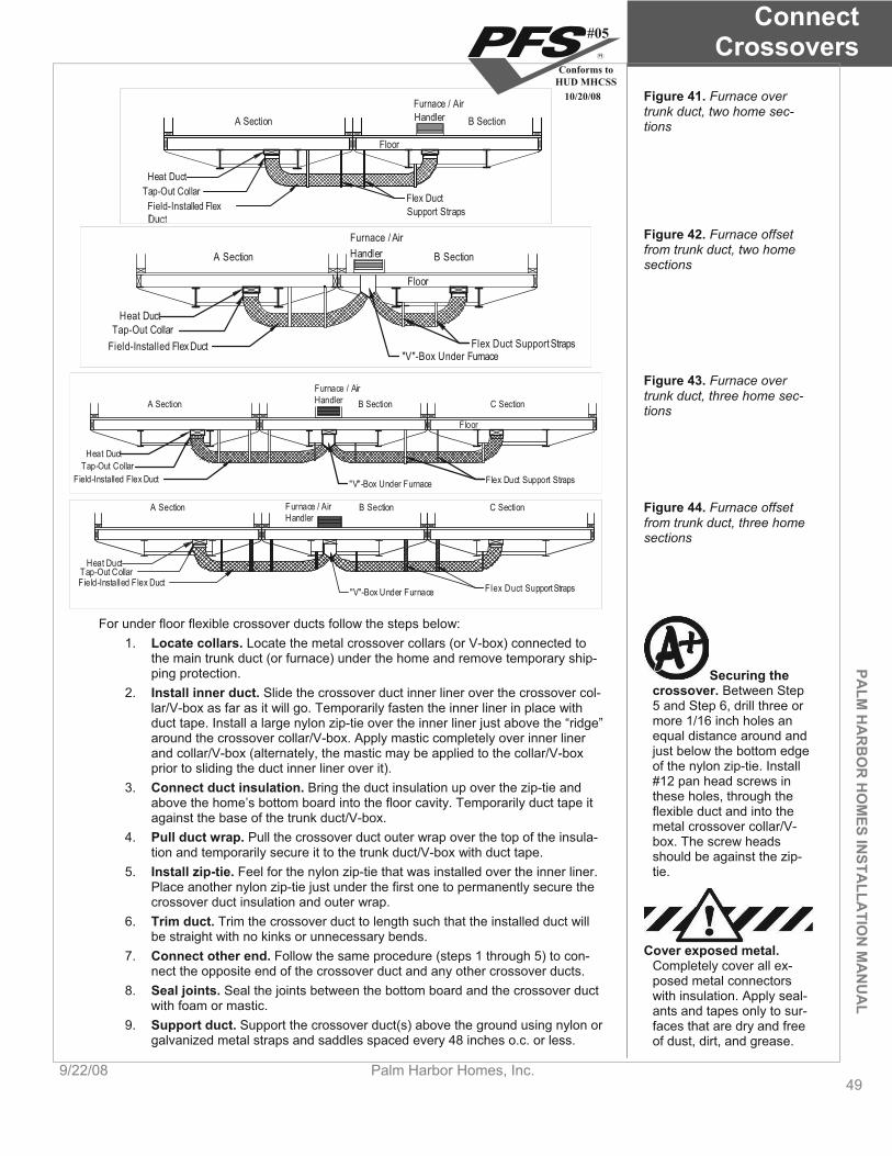
PALM
HA
RB
OR
HO
MES IN
STALLA
TION
MA
NU
AL
ConnectCrossovers
9/22/08 Palm Harbor Homes, Inc. 49
Furnace / AirHandler B SectionA Section
Heat DuctTap-Out Collar
Field-Installed FlexFlex DuctSupport Straps
Floor
Figure 41. Furnace over trunk duct, two home sec-tions
Furnace / AirHandler B SectionA Section
Floor
Flex Duct Support Straps
Heat DuctTap-Out Collar
Field-Installed Flex Duct"V"-Box Under Furnace
Figure 42. Furnace offset from trunk duct, two home sections
Furnace / AirHandlerA Section B Section C Section
Flex Duct Support Straps"V"-Box Under Furnace
Heat DuctTap-Out Collar
Field-Installed Flex Duct
Floor
Figure 43. Furnace over trunk duct, three home sec-tions
Furnace / AirHandler
A Section B Section C Section
Flex Duct Support Straps"V"-Box Under Furnace
Heat DuctTap-Out CollarField-Installed Flex Duct
Figure 44. Furnace offset from trunk duct, three home sections
For under floor flexible crossover ducts follow the steps below: 1. Locate collars. Locate the metal crossover collars (or V-box) connected to
the main trunk duct (or furnace) under the home and remove temporary ship-ping protection. Securing the
crossover. Between Step 5 and Step 6, drill three or more 1/16 inch holes an equal distance around and just below the bottom edge of the nylon zip-tie. Install #12 pan head screws in these holes, through the flexible duct and into the metal crossover collar/V-box. The screw heads should be against the zip-tie.
2. Install inner duct. Slide the crossover duct inner liner over the crossover col-lar/V-box as far as it will go. Temporarily fasten the inner liner in place with duct tape. Install a large nylon zip-tie over the inner liner just above the “ridge” around the crossover collar/V-box. Apply mastic completely over inner liner and collar/V-box (alternately, the mastic may be applied to the collar/V-box prior to sliding the duct inner liner over it).
3. Connect duct insulation. Bring the duct insulation up over the zip-tie and above the home’s bottom board into the floor cavity. Temporarily duct tape it against the base of the trunk duct/V-box.
4. Pull duct wrap. Pull the crossover duct outer wrap over the top of the insula-tion and temporarily secure it to the trunk duct/V-box with duct tape.
5. Install zip-tie. Feel for the nylon zip-tie that was installed over the inner liner. Place another nylon zip-tie just under the first one to permanently secure the crossover duct insulation and outer wrap.
6. Trim duct. Trim the crossover duct to length such that the installed duct will be straight with no kinks or unnecessary bends.
Cover exposed metal.Completely cover all ex-posed metal connectors with insulation. Apply seal-ants and tapes only to sur-faces that are dry and free of dust, dirt, and grease.
7. Connect other end. Follow the same procedure (steps 1 through 5) to con-nect the opposite end of the crossover duct and any other crossover ducts.
8. Seal joints. Seal the joints between the bottom board and the crossover duct with foam or mastic.
9. Support duct. Support the crossover duct(s) above the ground using nylon or galvanized metal straps and saddles spaced every 48 inches o.c. or less.
#05
Conforms toHUD MHCSS
10/20/08

ConnectCrossovers
50Palm Harbor Homes, Inc. 9/22/08
PALM
HA
RB
OR
HO
MES
INST
ALL
ATI
ON
MA
NU
AL
Avoid ground contact. In-stalled crossover ducts must not be in contact with the ground.
Choose straps at least 1/2 inch wider than the spacing of the metal spirals en-casing the crossover duct. Install the straps so they cannot slip between spi-rals. Secure metal straps with galvanized screws.
ROOF CAVITY CROSSOVER DUCT Unobstructed airflow. Ex-cess length, kinks and bends in the crossover duct will restrict airflow and de-grade the home’s HVAC system performance.
For ducts installed in the roof cavity, follow the steps below: 1. Access duct. Access the crossover location through an access panel in the
roof and remove any temporary shipping protection. 2. Join ducts. Using the provided flexible duct, join the distribution boxes in
each section of the home as shown in Figure 45, cutting off any extra duct length to keep the duct as straight as possible. The duct is connected to one side of the home.
3. Fasten ducts. At each connection point between ducts and between ducts and distribution boxes or connectors, secure the inner duct liner with a nylon strap, apply mastic completely over the connection area, pull the duct insula-tion and outer liner over the connection area, and secure them with a second nylon strap.
4. Reinstall panel. Reinstall and secure the access panel. Install underlayment and shigles as necessary.
Figure 45. Duct crossover located in the roof cavity
STEP 2. CONNECT ELECTRICAL CROSSOVERS Multi-section homes may have one or more electrical crossovers located in the wall(s) and/or floor(s) along the marriage line(s).
Use qualified electricians.All electrical work must be performed by a qualified electrician and comply with the 2005 NEC.
JOINING WIRES Two types of connections may be present at these locations—snap connectors and junction boxes. Identify matching circuits if multiple circuits exist at a single crossover location. These will be coded for identification. Connect snap connectors according to the connector manufacturer’s installation instructions, including fastener requirements.
Disconnect power. Turn off power to the home before making connections.
Connect wires in junction boxes as follows (Figure 46):Pull wires. Pull circuit wires into the junction box, sliding them through a romex con-nector and secure snugly. (Figure 46) Do not over-tighten. Proper use of GFCI cir-
cuits. Ensure Ground Fault Circuit Interrupted (GFCI) circuits are connected to the proper GFCI protected circuits from the power supply.
1. Strip wires. Remove the outer jacket that holds the circuit wires together pro-viding a minimum of four inches of free wire in the box.
2. Connect wires. Connect wires together matching like colors, using appropri-ately sized wire nuts. Use the ground wire to ground the junction box and/or cover plate(s), if metal. Junction boxes may contain single or multiple 15 or 20-amp circuits, or a single 240-volt appliance circuit.
3. Replace cover. Reposition the junction box cover and secure using machine (not sheet metal) screws. Figure 46. Types of junction
box wiring connections
#05
Conforms toHUD MHCSS
10/20/08
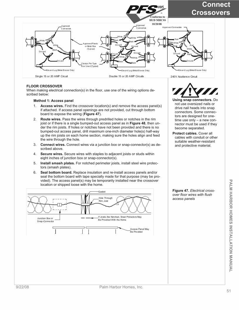
PALM
HA
RB
OR
HO
MES IN
STALLA
TION
MA
NU
AL
ConnectCrossovers
9/22/08 Palm Harbor Homes, Inc. 51
240V Appliance Circuit
A pproved Connectors
Ground
Ground
Red
Red
Whi te
Whi teBlack
Black
Ground Lug (Metal B ox es Only)
Single 15 or 20 AMP Circuit
A pprovedConnectors
Ground Lug (Metal B ox es Only)
Ground
Ground
Whi te
Whi teBlack
Black
Double 15 or 20 AMP Circuits
A pproved P las ticor Meta l Box
(Ty pical)
C lamps Per TypeB ox Used (Typical)
A pprovedConnectors
GroundGround
GroundGround
Whi te Whi te
Whi te Whi te
BlackBlack
BlackBlack
Ground Lug (Metal B ox es Only)
FLOOR CROSSOVER When making electrical connection(s) in the floor, use one of the wiring options de-scribed below:
Method 1: Access panel 1. Access wires. Find the crossover location(s) and remove the access panel(s)
if attached. If access panel openings are not provided, cut through bottom board to expose the wiring (Figure 47).
2. Route wires. Pass the wires through predrilled holes or notches in the rim joist or if there is a single bumped-out access panel as in Figure 48, then un-der the rim joists. If holes or notches have not been provided and there is no bumped-out access panel, drill maximum one-inch diameter hole(s) half-way up the rim joists on each home section, making sure the holes align and feed the wire through the hole.
3. Connect wires. Connect wires via a junction box or snap-connector(s) as de-scribed above.
4. Secure wires. Secure wires with staples to adjacent joists or studs within eight inches of junction box or snap-connector(s).
5. Install smash plates. For notched perimeter joists, install steel wire protec-tors (smash plates).
6. Seal bottom board. Replace insulation and re-install access panels and/or seal the bottom board with tape specially made for that purpose (may be pro-vided). The access panel(s) may be temporarily installed near the crossover location or shipped loose with the home.
Using snap connectors. Do not use oversized nails or drive nail heads into snap connectors. Some connec-tors are designed for one-time use only – a new con-nector must be used if they become separated.
Protect cables. Cover all cables with conduit or other suitable weather-resistant and protective material.
Junction Box orSnap-Connector
If Joists Are Notched, Steel Protectors MayBe Provided With the Home
Access Panel MayBe Provided
Hole ThroughRim Joist
Gasket Figure 47. Electrical cross-over floor wires with flush access panels
#05
Conforms toHUD MHCSS
10/20/08

ConnectCrossovers
52Palm Harbor Homes, Inc. 9/22/08
PALM
HA
RB
OR
HO
MES
INST
ALL
ATI
ON
MA
NU
AL
Junction Box or Snap Connector Protect ive Cover(If Not Provided, Patch Bottom
Board.)
Figure 48. Floor electrical crossover wires with bumped-out access panel
Method 2: Junction box with conduit 1. Access boxes. If junction boxes are not exposed, access them inside the
floor by cutting the bottom board or by removing the access panel(s). Remove the junction box covers.
2. Connect wires. If wire is coiled inside one junction box, insert it into provided flexible conduit and pass it under the rim joists to the opposing box and make the connection as described above. If no coiled wire is provided, install pro-vided ship-loose conduit with wire making connections in both boxes (Figure 49).
3. Cover boxes. Replace and secure covers on junction boxes. 4. Seal floor. Replace any displaced insulation and replace access panel or seal
the bottom board with tape specially made for that purpose (may be provided). Variation to Method 2: A junction box may be installed only on one side with the other side containing conduit behind an access panel. Bring the conduit to other side and make one connection in the junction box.
Junction Box (May Be Underor Alongside Floor Joist
Wire For CrossoverMay Be Coiled InsideJunction Box
Flexible Conduit
Figure 49. Under the rim joist electrical crossover connection with conduit
WALL CROSSOVERS Connect electrical, phone, cable television, and stereo speaker wires in marriage walls and/or partition and end walls.
Avoid damaging crossover wires. Carefully fold mar-riage wall crossover wires so they stay within a single bay and are not sand-wiched between studs when the sections are pulled together.
If access panels into the marriage walls are not provided, then the connection should have been made prior to bringing the home sections together. If access panels are provided in marriage, end or partition walls, remove the panels, join the wires as described above using the provided snap-connector, junction box, or at a receptacle, and re-attach the access panel (Figure 50 for marriage walls and Figure 51 for partitions and end walls).
#05
Conforms toHUD MHCSS
10/20/08

PALM
HA
RB
OR
HO
MES IN
STALLA
TION
MA
NU
AL
ConnectCrossovers
9/22/08 Palm Harbor Homes, Inc. 53
OptionalAccessPanel
Connect Wiresat Junction Box,Receptacle, orSnap-Connector
Figure 50. Inside marriage wall crossover connection
EndwallSide 'A'
Access to JunctionBox-Inside Home
Factory-InstalledWire Protectors
EndwallSide 'B'
FloorFloor
MarriageLine
Figure 51. Inside partition or end wall electrical crossover connection
STEP 3. INSTALL ELECTRICAL BONDING To ensure all metal parts are effectively grounded, electrically bond all chasses to-gether as follows (Figure 52):
1. Find lugs. Determine if solderless ground lugs are provided on the front or rear frame outriggers or headers.
2. Attach wire. If lugs are provided, uncoil the bonding wire (#8 minimum bare copper wire) from one side of the home and connect it to the lug provided on the opposing side using the provided paint penetrating star washer, tighten the set screw firmly on the wire and repeat for any additional home sections.
Rear Outrigger atMarriage Line
Solderless Lug EachHalf of Home
#8 Min. CopperGround Wire
Marriage Line
Floor
Figure 52. Electrical bonding of multi-section homes
3. Attach strap. If ground lugs and copper wire are not provided, attach the pro-vided four-inch bonding strap to each pair of adjacent chasses with two #8 x 3/4” self-tapping metal screws (one screw each side).
STEP 4. CONNECT WATER LINES Connect water lines inside the floor through access panels or below the bottom board as follows:
WATER LINES ACCESSED THROUGH PANELS Applying cement. Follow cement manufacturers in-structions with respect to application and drying time. Allow cement to fully cure
1. Remove panels. Remove access panels from each home section. 2. Remove caps. Remove shipping caps from ends of water lines. 3. Pull lines. Pull water lines through holes in rim joist. If holes are not provided,
#05
Conforms toHUD MHCSS
10/20/08
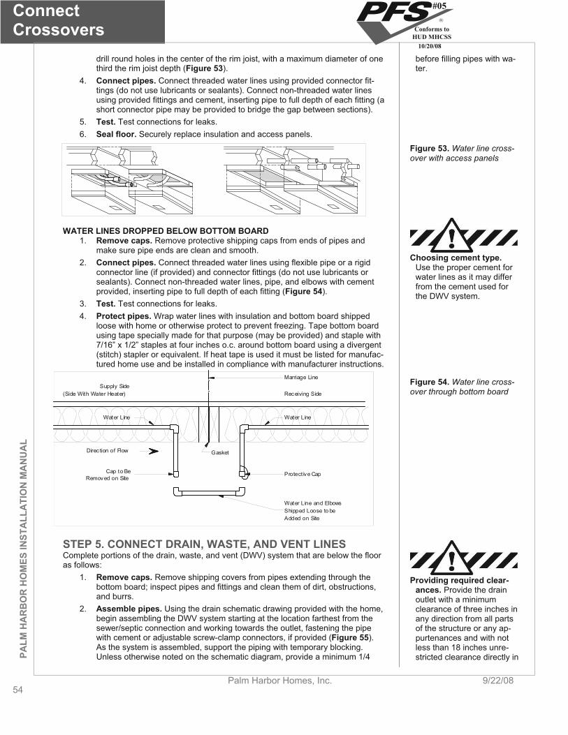
ConnectCrossovers
54Palm Harbor Homes, Inc. 9/22/08
PALM
HA
RB
OR
HO
MES
INST
ALL
ATI
ON
MA
NU
AL
drill round holes in the center of the rim joist, with a maximum diameter of one third the rim joist depth (Figure 53).
4. Connect pipes. Connect threaded water lines using provided connector fit-tings (do not use lubricants or sealants). Connect non-threaded water lines using provided fittings and cement, inserting pipe to full depth of each fitting (a short connector pipe may be provided to bridge the gap between sections).
5. Test. Test connections for leaks. 6. Seal floor. Securely replace insulation and access panels.
before filling pipes with wa-ter.
Figure 53. Water line cross-over with access panels
WATER LINES DROPPED BELOW BOTTOM BOARD 1. Remove caps. Remove protective shipping caps from ends of pipes and
make sure pipe ends are clean and smooth. 2. Connect pipes. Connect threaded water lines using flexible pipe or a rigid
connector line (if provided) and connector fittings (do not use lubricants or sealants). Connect non-threaded water lines, pipe, and elbows with cement provided, inserting pipe to full depth of each fitting (Figure 54).
3. Test. Test connections for leaks. 4. Protect pipes. Wrap water lines with insulation and bottom board shipped
loose with home or otherwise protect to prevent freezing. Tape bottom board using tape specially made for that purpose (may be provided) and staple with 7/16” x 1/2” staples at four inches o.c. around bottom board using a divergent (stitch) stapler or equivalent. If heat tape is used it must be listed for manufac-tured home use and be installed in compliance with manufacturer instructions.
Choosing cement type.Use the proper cement for water lines as it may differ from the cement used for the DWV system.
Water Line Water Line
Protect ive CapCap to BeRemoved on Site
Direc tion of Flow
Water Line and ElbowsShipped Loose to beAdded on Site
Receiving SideSupply Side
(Side With Water Heater)
Marriage Line
Gasket
Figure 54. Water line cross-over through bottom board
STEP 5. CONNECT DRAIN, WASTE, AND VENT LINES Complete portions of the drain, waste, and vent (DWV) system that are below the floor as follows:
1. Remove caps. Remove shipping covers from pipes extending through the bottom board; inspect pipes and fittings and clean them of dirt, obstructions, and burrs.
Providing required clear-ances. Provide the drain outlet with a minimum clearance of three inches in any direction from all parts of the structure or any ap-purtenances and with not less than 18 inches unre-stricted clearance directly in
2. Assemble pipes. Using the drain schematic drawing provided with the home, begin assembling the DWV system starting at the location farthest from the sewer/septic connection and working towards the outlet, fastening the pipe with cement or adjustable screw-clamp connectors, if provided (Figure 55).As the system is assembled, support the piping with temporary blocking. Unless otherwise noted on the schematic diagram, provide a minimum 1/4
#05
Conforms toHUD MHCSS
10/20/08
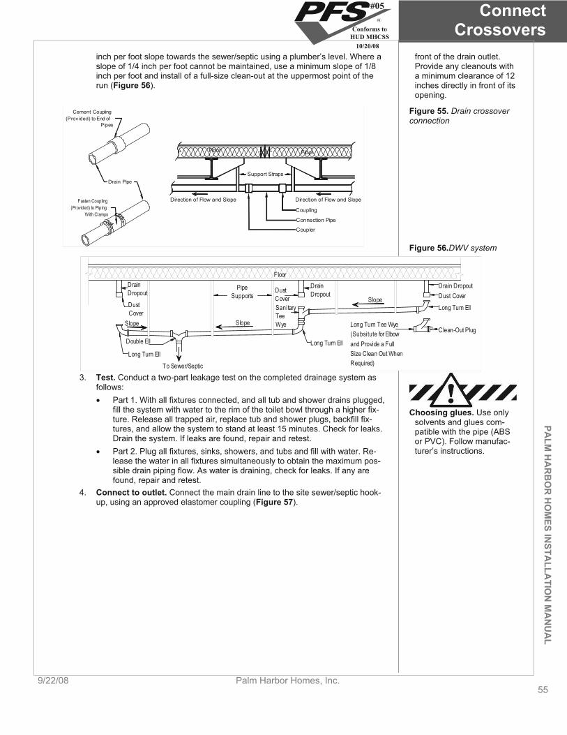
PALM
HA
RB
OR
HO
MES IN
STALLA
TION
MA
NU
AL
ConnectCrossovers
9/22/08 Palm Harbor Homes, Inc. 55
front of the drain outlet. Provide any cleanouts with a minimum clearance of 12 inches directly in front of its opening.
inch per foot slope towards the sewer/septic using a plumber’s level. Where a slope of 1/4 inch per foot cannot be maintained, use a minimum slope of 1/8 inch per foot and install of a full-size clean-out at the uppermost point of the run (Figure 56).
Drain Pipe
Cement Coupling(Provided) to End of
Pipes
Fasten Coupling(Provided) to Piping
With Clamps
Direction of Flow and Slope
Support Straps
Floor Floor
Coupling
Connection Pipe
Coupler
Direction of Flow and Slope
Figure 55. Drain crossover connection
Figure 56.DWV system
Floor
Slope
Slope
DrainDropout
DustCover
Drain DropoutDust Cover
Long Turn Ell
Double Ell
To Sewer/Septic
SanitaryTeeWye
Long Turn Ell
Long Turn Ell
Long Turn Tee Wye(Subsitute for Elbowand Provide a FullSize Clean Out WhenRequired)
Clean-Out PlugSlope
DrainDropoutDust
CoverPipe
Supports
3. Test. Conduct a two-part leakage test on the completed drainage system as follows: Part 1. With all fixtures connected, and all tub and shower drains plugged,
fill the system with water to the rim of the toilet bowl through a higher fix-ture. Release all trapped air, replace tub and shower plugs, backfill fix-tures, and allow the system to stand at least 15 minutes. Check for leaks. Drain the system. If leaks are found, repair and retest.
Choosing glues. Use only solvents and glues com-patible with the pipe (ABS or PVC). Follow manufac-turer’s instructions. Part 2. Plug all fixtures, sinks, showers, and tubs and fill with water. Re-
lease the water in all fixtures simultaneously to obtain the maximum pos-sible drain piping flow. As water is draining, check for leaks. If any are found, repair and retest.
4. Connect to outlet. Connect the main drain line to the site sewer/septic hook-up, using an approved elastomer coupling (Figure 57).
#05
Conforms toHUD MHCSS
10/20/08

ConnectCrossovers
56Palm Harbor Homes, Inc. 9/22/08
PALM
HA
RB
OR
HO
MES
INST
ALL
ATI
ON
MA
NU
AL
ApprovedCoupler
Site SewerHook Up
Cap and Chain
Support Strap ata Maximum of 4Feet on Center
Flow
Flow
Examples ofConnection Pipeand Fittings (NotSupplied by the
Manufacturer)
Floor
Figure 57. DWV connection to sewer/septic
5. Install supports. Install permanent drain line supports at a distance of four feet o.c. or less (see Figure 55, Figure 57, and Figure 58).
0.131" Dia x 3 14" Nail
Galv . or Alum. Strip
Min. 1x3 Lumber
Drain Pipe
Min. 2x3 Lumber
(2) 0.131" Dia x 3 14" Nails
Min. 2x3 Lumber
Galv. or Alum Strip
(2) Staples orScrews Each Side
(2) 716" x 2" x 16GA
Staples or (2)0.131" Dia x 3 1
4"Nails Each End
(2) 0.131" Dia x 3 14"
Nails Into Floor Joist
Figure 58. DWV pipe sup-port options
Protect pipes from freez-ing. If the home is to be left unheated in cold weather, pour antifreeze solution into all drain traps, including sinks, tubs, and toilets. Be sure that the antifreeze is safe for the fixtures and P-traps.
Installing quick disconnect fittings. Do not use tools, lubricants, or sealants with quick disconnect fittings.
6. Insulate. Replace all insulation and make sure all potentially exposed portions of the DWV system are well insulated to protect against freezing.
Gas test precautions. Do not connect to gas service until tests described in Connect Utilities have been successfully completed.
STEP 6. CONNECT GAS LINES The gas crossover connection may use quick disconnect fittings or threaded connec-tors. Find the connection location below the floor at the marriage line and gather the connectors (they may be shipped loose if not present under the home).
For quick disconnect fittings (Figure 59), remove any dust caps and then with one hand, pull back on the quick disconnect device, snap it over the quick disconnect adap-tor and release it to complete the connection.
For threaded connectors (Figure 60), remove the black cap and nipple (or any other plugs, such as a black iron plug) from both the supply and receiving sides and screw the connector onto the supply and return pipes as necessary.
Check for leaks before connecting to gas service (see Connect Utilities, STEP 3. CONNECT GAS SERVICE, p. 81).
#05
Conforms toHUD MHCSS
10/20/08

PALM
HA
RB
OR
HO
MES IN
STALLA
TION
MA
NU
AL
ConnectCrossovers
9/22/08 Palm Harbor Homes, Inc. 57
Quick-DisconnectMale Fitting FlexFactory Installed
Quick-DisconnectFemale FittingInstalled on lnlet Side
Male Cap
Female CapFemale Cap
Flex ConnectorFactory Installed
Male Cap
Or
Shut-Off ValveInstalled onInlet Side
Direction of Gas FlowDirection of Gas Flow
Figure 59. Gas crossover with quick disconnect fittings
Figure 60. Gas crossover with threaded connectors
Installing wiring. When in-stalling telephone and ca-ble television wires, do not damage electrical wires, plumbing lines, or ducts. Serious personal injury or death could result from damage to electrical wires.
STEP 7. CONNECT TELEPHONE AND CABLE TV WIRING Install telephone and cable television wiring in accordance with the requirements of the LAHJ, the NEC, and NFPA No.70-2005. When making crossover connections or in-stalling telephone or cable television wires, do not run them in the same raceway as, or in close proximity to, high voltage electrical conductors or cables.
Wires should only be installed by trained professionals.
go to Complete the Interior (p. 58)
#05
Conforms toHUD MHCSS
10/20/08

Complete the Interior
58Palm Harbor Homes, Inc. 9/22/08
PALM
HA
RB
OR
HO
MES
INST
ALL
ATI
ON
MA
NU
AL
Complete the Interior This chapter covers the completion of the home’s interior finishes including finishing walls, ceilings, flooring, trim, and mis-cellaneous items.
Follow the Steps below:
STEP 1. ALIGN MARRIAGE WALLS (p. 58)
STEP 2. FINISH GYPSUM BOARD (p. 58)
STEP 3 58). COMPLETE WALL AND CEILING FINISHES (p.
STEP 4. COMPLETE CARPET (p. 59)
STEP 5. COMPLETE TRIM (p. 59)
STEP 6. INSTALL SHIP LOOSE ITEMS (p. 59)
STEP 1. ALIGN MARRIAGE WALLS Align and secure walls at marriage line openings as follows:
1. Align walls. Align walls and clamp in place. 2. Fasten walls. Secure clamped walls together with metal straps or long
screws so they do not move when the clamps are removed. Insert wood wedges in gaps between walls, and glue and screw to create a tight connec-tion.
3. Fill gaps. Fill any remaining gaps with wood or sheathing material.
Does the home require patching and finishing gypsum board walls or ceil-ings?
YES, go to STEP 2. FINISH GYPSUM BOARD, (p. 58) NO, go to STEP 3. COMPLETE WALL AND CEILING PANELS, (p.
58).
STEP 2. FINISH GYPSUM BOARD Finish all unfinished gypsum board walls and ceilings as follows:
1. Install panels. Install ship loose gypsum panels using a 1/4 inch diameter bead of adhesive on all framing members and minimum 1-1/2 inch long dry-wall screws, nails, or staples at six inches o.c. along panel edges and 12 inches o.c. in the field into framing members.
Fastening gypsum. When attaching gypsum board, depress, but do not break the paper face with the fas-tener. Breaking the paper will weaken the connection.
2. Mud seams. Mud and tape all seams and corners, filling all fastener depres-sions. Follow mud manufacturer’s directions.
3. Paint. When the final coat of mud is dry, prime and paint all unfinished gyp-sum board to match existing paint color and finish texture. Using alternative materials.
Obtain the home manufac-turer’s approval before us-ing interior finish materials other than those provided with the home.
Does the home have pre-finished interior wall panels at the marriage line? YES, go to STEP 3. COMPLETE WALL AND CEILING PANELS, (p. 58)
NO, go to STEP 4. COMPLETE CARPET, (p. 59).
STEP 3. COMPLETE WALL AND CEILING FINISHES Install interior ship loose wall and/or ceiling panels using a 1/4 inch diameter bead of polyvinyl acetate (PVA) adhesive on all framing members and fasten with minimum 1-
#05
Conforms toHUD MHCSS
10/20/08

PALM
HA
RB
OR
HO
MES IN
STALLA
TION
MA
NU
AL
Complete the Interior
9/22/08 Palm Harbor Homes, Inc. 59
1/2 inch long staples or nails at six inches o.c. along panel edges and 12 inches o.c. in the field into framing members.
STEP 4. COMPLETE CARPET Install and seam ship loose or rolled carpet as follows:
1. Prepare floor. Clean the floor of all dirt and debris and smooth the floor deck at the marriage line seams as necessary to ensure a level and smooth sur-face.
Installing carpet. Only ex-perienced carpet installers should install carpet. Fail-ure to follow the carpet manufacturer’s directions may void the carpet war-ranty.
2. Lay pad. Lay down the carpet pad, if provided. 3. Stretch carpet. Ensuring all carpet “grain” runs in the same direction, fit and
secure the carpet using a power carpet stretcher. Stretch the carpet up to the seam and tack it down temporarily until the carpet is seamed.
4. Butter carpet. “Butter” with carpet adhesive the edges of the carpet along the seam.
5. Seam carpet. Place heat bond tape under the seam with the glue side next to the carpet and apply heat from a seaming iron to the top of the seam, press-ing the carpet into the glue. Stagger seams.
Stagger all seams. For ex-ample, locate the carpet pad seam three inches to left of marriage line and the carpet seam three inches to right of marriage line.
6. Keep scraps. Retain reasonable size carpet scraps to protect carpet and flooring during move-in.
STEP 5. COMPLETE TRIM Using fine gauge wire staples or pin nails, install ship loose molding and wainscot pan-eling to finish trimming out ceilings, marriage line walls, front and rear end walls, and passageway doors where necessary.
STEP 6. INSTALL SHIP LOOSE ITEMS Remove all strapping, blocking, and packaging from appliances, windows, and doors. Install any drapes, mini-blinds, mirrors, door stops, closet shelves, and hardware per the product manufacturer’s installation instructions.
Proceed based on the foundation type: Pier and ground anchor, go to Install Stabilizing Systems, (p. 60)Load bearing perimeter wall, go to Connect Utilities (p. 75).
#05
Conforms toHUD MHCSS
10/20/08
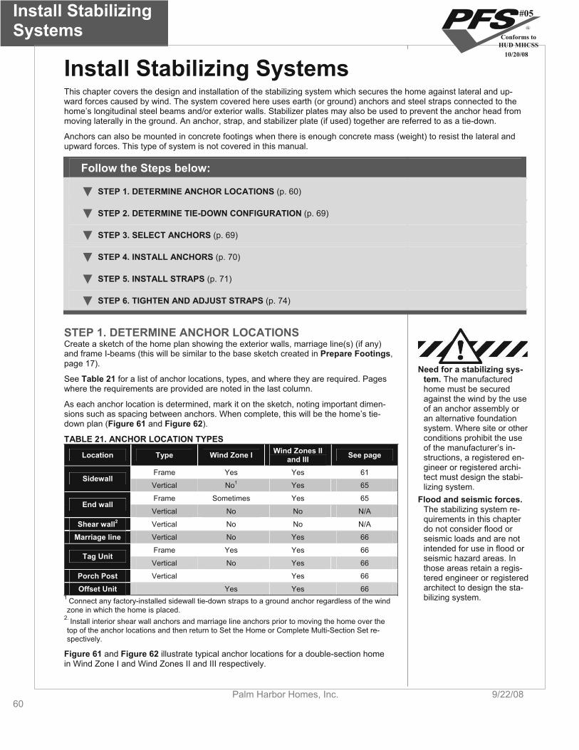
Install Stabilizing Systems
60Palm Harbor Homes, Inc. 9/22/08
Install Stabilizing Systems This chapter covers the design and installation of the stabilizing system which secures the home against lateral and up-ward forces caused by wind. The system covered here uses earth (or ground) anchors and steel straps connected to the home’s longitudinal steel beams and/or exterior walls. Stabilizer plates may also be used to prevent the anchor head from moving laterally in the ground. An anchor, strap, and stabilizer plate (if used) together are referred to as a tie-down.
Anchors can also be mounted in concrete footings when there is enough concrete mass (weight) to resist the lateral and upward forces. This type of system is not covered in this manual.
Follow the Steps below:
STEP 1. DETERMINE ANCHOR LOCATIONS (p. 60)
STEP 2. DETERMINE TIE-DOWN CONFIGURATION (p. 69)
STEP 3. SELECT ANCHORS (p. 69)
STEP 4. INSTALL ANCHORS (p. 70)
STEP 5. INSTALL STRAPS (p. 71)
STEP 6. TIGHTEN AND ADJUST STRAPS (p. 74)
STEP 1. DETERMINE ANCHOR LOCATIONS Create a sketch of the home plan showing the exterior walls, marriage line(s) (if any) and frame I-beams (this will be similar to the base sketch created in Prepare Footings,page 17).
Need for a stabilizing sys-tem. The manufactured home must be secured against the wind by the use of an anchor assembly or an alternative foundation system. Where site or other conditions prohibit the use of the manufacturer’s in-structions, a registered en-gineer or registered archi-tect must design the stabi-lizing system.
See Table 21 for a list of anchor locations, types, and where they are required. Pages where the requirements are provided are noted in the last column.
As each anchor location is determined, mark it on the sketch, noting important dimen-sions such as spacing between anchors. When complete, this will be the home’s tie-down plan (Figure 61 and Figure 62).
TABLE 21. ANCHOR LOCATION TYPES Wind Zones II Location Type Wind Zone I See page and III
Frame Yes Yes 61Sidewall
No1Vertical Yes 65
Frame Sometimes Yes 65 Flood and seismic forces. The stabilizing system re-quirements in this chapter do not consider flood or seismic loads and are not intended for use in flood or seismic hazard areas. In those areas retain a regis-tered engineer or registered architect to design the sta-bilizing system.
End wall Vertical No No N/A
Shear wall2 Vertical No No N/A
Marriage line Vertical No Yes 66
Frame Yes Yes 66Tag Unit
Vertical No Yes 66
Porch Post Vertical Yes 66
Offset Unit Yes Yes 661 Connect any factory-installed sidewall tie-down straps to a ground anchor regardless of the wind zone in which the home is placed.
2. Install interior shear wall anchors and marriage line anchors prior to moving the home over the top of the anchor locations and then return to Set the Home or Complete Multi-Section Set re-spectively.
Figure 61 and Figure 62 illustrate typical anchor locations for a double-section home in Wind Zone I and Wind Zones II and III respectively.
#05
Conforms toHUD MHCSS
10/20/08
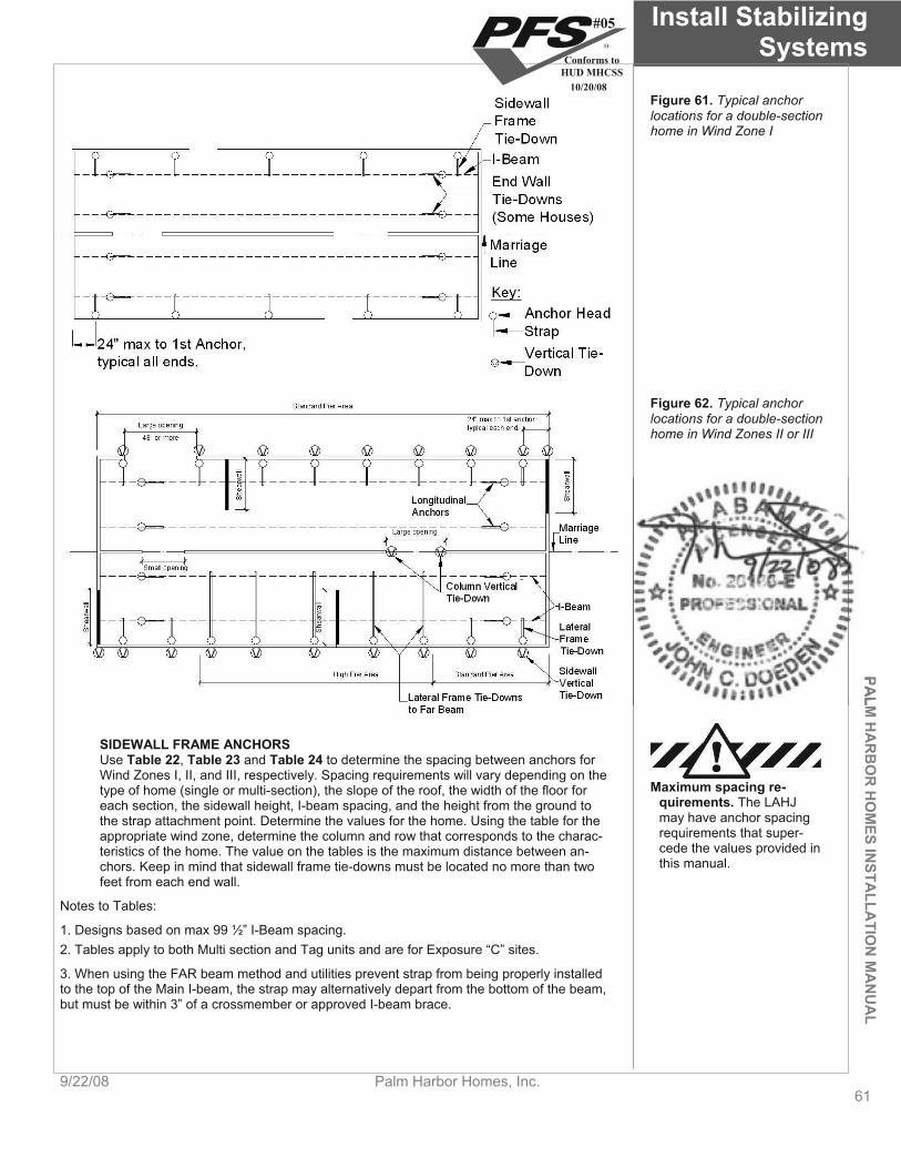
PALM
HA
RB
OR
HO
MES IN
STALLA
TION
MA
NU
AL
Install Stabilizing Systems
9/22/08 Palm Harbor Homes, Inc. 61
Figure 61. Typical anchor locations for a double-section home in Wind Zone I
Figure 62. Typical anchor locations for a double-section home in Wind Zones II or III
SIDEWALL FRAME ANCHORS Use Table 22, Table 23 and Table 24 to determine the spacing between anchors for Wind Zones I, II, and III, respectively. Spacing requirements will vary depending on the type of home (single or multi-section), the slope of the roof, the width of the floor for each section, the sidewall height, I-beam spacing, and the height from the ground to the strap attachment point. Determine the values for the home. Using the table for the appropriate wind zone, determine the column and row that corresponds to the charac-teristics of the home. The value on the tables is the maximum distance between an-chors. Keep in mind that sidewall frame tie-downs must be located no more than two feet from each end wall.
Maximum spacing re-quirements. The LAHJ may have anchor spacing requirements that super-cede the values provided in this manual.
Notes to Tables:
1. Designs based on max 99 ½” I-Beam spacing. 2. Tables apply to both Multi section and Tag units and are for Exposure “C” sites.
3. When using the FAR beam method and utilities prevent strap from being properly installed to the top of the Main I-beam, the strap may alternatively depart from the bottom of the beam, but must be within 3” of a crossmember or approved I-beam brace.
#05
Conforms toHUD MHCSS
10/20/08

Install Stabilizing Systems
62Palm Harbor Homes, Inc. 9/22/08
TABLE 22. WIND ZONE I SIDEWALL FRAME ANCHOR MAXIMUM SPACING Roof slope maximum 4.35/12
(20 degrees) Roof slope maximum 6/12
(26.5 degrees)
Floor width Sidewall height
I-beam spac-ing
Height from ground to strap at-tachment
Single section or Double section
Single section or Double section
20” to 24” 11’-3” 7’-3”
25” to 32” 9’-3” 5’-9”
33” to 40” 7’-10” 4’-9”
41” to 48” 6’-9” 4’-0”
49” to 56 5’-11” 3’-6”
Up to 7’-6” 99 ½” max.
57” to 64” 5’-3” N/A
20” to 24” 9’-6” 6’-3”
25” to 32” 7’-10” 5’-0”
33” to 40” 6’-8” 4’-2”
41” to 48” 5’-9” 3’-6”
49” to 56 5’-0” 3’-0”
140” min.
More than 7’-6” to9’-0”
99 ½” max.
57” to 64” 4’-5” N/A
20” to 24” 13’-9” 9’-10”
25” to 32” 12’-0” 8’-4”
33” to 40” 10’-7” 7’-2”
41” to 48” 9’-4” 6’-3”
49” to 56 8’-4” 5’-6”
Up to 7’-6” 99 ½” max.
57” to 64” 7’-6” 4’-11”
20” to 24” 11’-6” 8’-7”
25” to 32” 10’-2” 7’-3”
33” to 40” 8’-10” 6’-3”
41” to 48” 7’-10” 5’-5”
49” to 56 7’-0” 4’-9”
160” min
More than 7’-6” to9’-0”
99 ½” max.
57” to 64” 6’-4” 4’-3”
20” to 24” 15’-3” 11’-4”
25” to 32” 14’-0” 10’-3”
33” to 40” 12’-10” 9’-2”
41” to 48” 11’-8” 8’-3”
49” to 56 10’-8” 7’-6”
Up to 7’-6” 99 ½” max.
57” to 64” 9’-10” 6’-9”
20” to 24” 12’-8” 9’-11”
25” to 32” 11’-6” 9’-0”
33” to 40” 10’-5” 8’-0”
41” to 48” 9’-6” 7’-3”
49” to 56 8’-7” 6’-6”
186” min
More than 7’-6” to9’-0”
99 ½” max.
57” to 64” 7’-10” 5’-11”
20” to 24” 16’-0” 11’-8”
25” to 32” 15’-2” 10’-10”
33” to 40” 14’-2” 10’-0”
41” to 48” 13’-2” 9’-4”
49” to 56 12’-3” 8’-7”
Up to 7’-6” 99 ½” max.
57” to 64” 11’-5” 7’-11”
20” to 24” 13’-6” 10’-3”
25” to 32” 12’-9” 9’-7”
33” to 40” 11’-11” 8’-10”
41” to 48” 11’-2” 8’-2”
49” to 56 10’-4” 7’-6”
210” min
More than 7’-6” to9’-0”
99 ½” max.
57” to 64” 9’-8” 7’-0”
* Anchors and straps are installed along each side wall (must be opposite each other on single sections) see Figure 66.
#05
Conforms toHUD MHCSS
10/20/08

PALM
HA
RB
OR
HO
MES IN
STALLA
TION
MA
NU
AL
Install Stabilizing Systems
9/22/08 Palm Harbor Homes, Inc. 63
TABLE 23. SINGLE SECTION WIND ZONE II & III SIDEWALL FRAME ANCHOR MAXIMUM SPACING Maximum 4.35/12 roof pitch Wind Zone II Wind Zone III
Height from ground to strap Attachment (in)
Height from ground to strap Attachment (in)
Floor width Sidewall height
I-beam spac-ing
Sidewall vertical &
diagonal tie spacing
(ft) Near Beam Far Beam Near Beam Far Beam 4’-0” 46 80 34 80
5’-4” 30 80 20 80
6’-8” 20 80 n/a 46Up to 7’-6”
99 1/2 Max.
8’-0” n/a 52 n/a n/a
4’-0” 35 80 n/a 80
5’-4” 21 80 n/a 50
6’-8” n/a 46 n/a n/a
14 wide 160” min floor
width More than 7’-6” to9’-0”
99 1/2 Max.
8’-0” n/a n/a n/a n/a
4’-0” 70 80 50 80
5’-4” 44 80 28 80
6’-8” 28 80 n/a 46Up to 7’-6”
99 1/2 Max.
8’-0” n/a 54 n/a n/a
4’-0” 49 80 34 80
5’-4” 29 80 n/a 56
6’-8” n/a 52 n/a n/a
16 wide 180” min floor
width More than 7’-6” to9’-0”
99 1/2 Max.
8’-0” n/a n/a n/a n/a
4’-0” 80 80 64 80
5’-4” 56 80 36 80
6’-8” 36 80 20 46Up to 7’-6”
99 1/2 Max.
8’-0” n/a 54 n/a n/a
4’-0” 68 80 46 80
5’-4” 39 80 22 55
6’-8” n/a 52 n/a n/a
18 wide 210” floor width
More than 7’-6” to9’-0”
99 1/2 Max.
8’-0” n/a n/a n/a n/a
* For near and far beam installation, see Figure 66.Example: 18 ft wide x 60 ft long with 7’-6” side wall installed in Wind Zone II. Factory installed Vertical Tie spacing is 6ft-8in. The maximum height from anchor to bottom of floor must be 36” or less for “Near beam” attachment. The height may be increased to 80” when the “Far beam” method is used. Note: The maximum height from ground to strap attachment in-cludes the I-Beam height.
#05
Conforms toHUD MHCSS
10/20/08
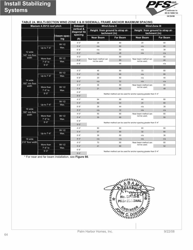
Install Stabilizing Systems
64Palm Harbor Homes, Inc. 9/22/08
TABLE 24. MULTI-SECTION WIND ZONE II & III SIDEWALL FRAME ANCHOR MAXIMUM SPACING Maxium 4.35/12 roof pitch Wind Zone II Wind Zone III
Height from ground to strap at-tachment (in)
Height from ground to strap at-tachment (in)
I-beam spac-ing
Sidewall vertical &
diagonal tie spacing
(ft) Near Beam Far Beam Near Beam Far Beam
4’-0” 28 80 20 80
5’-4” n/a 80 n/a 80
6’-8” n/a 80 n/a 38Up to 7’-6”
99 1/2 Max.
8’-0” n/a 48 n/a n/a
4’-0” 80 80
5’-4” 80 44
6’-8”
Near beam method can not be used.
46
Near beam method can not be used.
n/a
12 wide 140” min floor
width More than 7’-6” to9’-0”
99 1/2 Max.
4’-0” 46 80 33 80
5’-4” 32 80 n/a 80
6’-8” 20 80 n/a 40Up to 7’-6”
99 1/2 Max.
8’-0” n/a 52 n/a n/a
4’-0” 36 80 80
5’-4” 21 80
Near beam method can not be used.
48
6’-8”
14 wide 160” min floor
width More than 7’-6” to9’-0”
99 1/2 Max.
8’-0” Neither method can be used for anchor spacing greater than 5’-4”
4’-0” 64 80 44 80
5’-4” 40 64 24 80
6’-8” 26 44 n/a 38Up to 7’-6”
99 1/2 Max.
8’-0” n/a 32 n/a n/a
4’-0” 50 80 80
5’-4” 30 80
Near beam method can not be used.
50
6’-8”
16 wide 180” min floor
width More than 7’-6” to9’-0”
99 1/2 Max.
8’-0” Neither method can be used for anchor spacing greater than 5’-4”
4’-0” 80 80 60 80
5’-4” 57 80 32 80
6’-8” 36 80 n/a 36Up to 7’-6”
99 1/2 Max.
8’-0” n/a n/a n/a n/a
4’-0” 70 80 80
5’-4” 41 80
Near beam method can not be used.
52
6’-8”
18 wide 210” floor width
More than 7’-6” to9’-0”
99 1/2 Max.
8’-0” Neither method can be used for anchor spacing greater than 5’-4”
* For near and far beam installation, see Figure 66.
#05
Conforms toHUD MHCSS
10/20/08
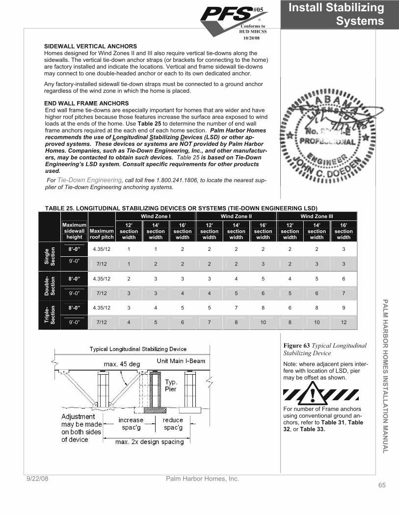
PALM
HA
RB
OR
HO
MES IN
STALLA
TION
MA
NU
AL
Install Stabilizing Systems
9/22/08 Palm Harbor Homes, Inc. 65
SIDEWALL VERTICAL ANCHORS Homes designed for Wind Zones II and III also require vertical tie-downs along the sidewalls. The vertical tie-down anchor straps (or brackets for connecting to the home) are factory installed and indicate the locations. Vertical and frame sidewall tie-downs may connect to one double-headed anchor or each to its own dedicated anchor.
Any factory-installed sidewall tie-down straps must be connected to a ground anchor regardless of the wind zone in which the home is placed.
END WALL FRAME ANCHORS End wall frame tie-downs are especially important for homes that are wider and have higher roof pitches because those features increase the surface area exposed to wind loads at the ends of the home. Use Table 25 to determine the number of end wall frame anchors required at the each end of each home section. Palm Harbor Homes recommends the use of Longitudinal Stabilizing Devices (LSD) or other ap-proved systems. These devices or systems are NOT provided by Palm Harbor Homes. Companies, such as Tie-Down Engineering, Inc., and other manufactur-ers, may be contacted to obtain such devices. Table 25 is based on Tie-Down Engineering’s LSD system. Consult specific requirements for other products used. For Tie-Down Engineering, call toll free 1.800.241.1806, to locate the nearest sup-plier of Tie-down Engineering anchoring systems.
TABLE 25. LONGITUDINAL STABILIZING DEVICES OR SYSTEMS (TIE-DOWN ENGINEERING LSD) Wind Zone I Wind Zone II Wind Zone III
Maximum 12’ 14’ 16’ 12’ 14’ 16’ 12’ 14’ 16’sidewall Maximum height roof pitch
section width
section width
section width
section width
section width
section width
section width
section section width width
8’-0” 4.35/12 1 1 2 2 2 2 2 2 3
Sing
leSe
ctio
n
9’-0” 7/12 1 2 2 2 2 3 2 3 3
8’-0” 4.35/12 2 3 3 3 4 5 4 5 6
Dou
ble-
Sect
ion
9’-0” 7/12 3 3 4 4 5 6 5 6 7
8’-0” 4.35/12 3 4 5 5 7 8 6 8 9
Trip
le-
Sect
ion
9’-0” 7/12 4 5 6 7 8 10 8 10 12
Figure 63 Typical Longitudinal Stabilizing Device
Note: where adjacent piers inter-fere with location of LSD, pier may be offset as shown.
For number of Frame anchors using conventional ground an-chors, refer to Table 31, Table 32, or Table 33.
#05
Conforms toHUD MHCSS
10/20/08
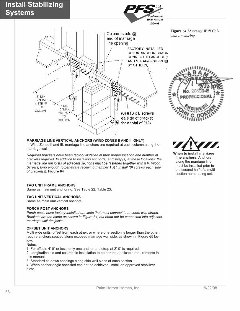
Install Stabilizing Systems
66Palm Harbor Homes, Inc. 9/22/08
Figure 64 Marriage Wall Col-umn Anchoring
MARRIAGE LINE VERTICAL ANCHORS (WIND ZONES II AND III ONLY) In Wind Zones II and III, marriage line anchors are required at each column along the marriage wall.
When to install marriage line anchors. Anchorsalong the marriage line must be installed prior to the second half of a multi-section home being set.
Required brackets have been factory installed at their proper location and number of brackets required. In addition to installing anchor(s) and strap(s) at these locations, the marriage line rim joists of adjacent sections must be fastened together with #10 Wood Screws, long enough to penetrate receiving member 1 ½”. Install (6) screws each side of bracket(s). Figure 64
TAG UNIT FRAME ANCHORS Same as main unit anchoring. See Table 22, Table 23.
TAG UNIT VERTICAL ANCHORS Same as main unit vertical anchors.
PORCH POST ANCHORS Porch posts have factory installed brackets that must connect to anchors with straps. Brackets are the same as shown in Figure 64, but need not be connected into adjacent marriage wall rim joists.
OFFSET UNIT ANCHORS Multi wide units, offset from each other, or where one section is longer than the other, require anchors spaced along exposed marriage wall side, as shown in Figure 65 be-low. Notes:1. For offsets 4’-0” or less, only one anchor and strap at 2’-0” is required. 2. Longitudinal tie and column tie installation to be per the applicable requirements in this manual. 3. Standard tie down spacings along side wall sides of each section. 4. When anchor angle specified can not be achieved, install an approved stabilizer plate.
#05
Conforms toHUD MHCSS
10/20/08
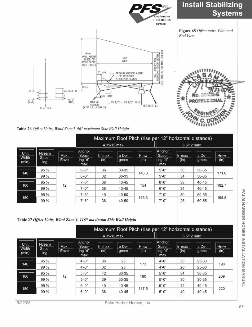
PALM
HA
RB
OR
HO
MES IN
STALLA
TION
MA
NU
AL
Install Stabilizing Systems
9/22/08 Palm Harbor Homes, Inc. 67
Figure 65 Offset units, Plan and End View
Table 26 Offset Units, Wind Zone I, 96" maximum Side Wall Height
Maximum Roof Pitch (rise per 12” horizontal distance) 4.35/12 max. 6.5/12 max.
Anchor AnchorUnit I-Beam Max. Width (min)
Spac-ing Eave
Spac- h max a De- Hmw ing “d” max
(in) grees (in)Spac- h max a De- Hmw ing “d” max
(in) grees (in)
95 ½ 6’-0” 36 30-35 5’-0” 38 30-35 140 146.8
99 ½ 6’-0” 32 30-35 5’-0” 34 30-35 171.8
95 ½ 7’-0” 38 40-45 6’-0” 38 40-45 160
99 ½ 7’-0” 36 40-45 154
6’-0” 34 40-45 182.712
95 ½ 7’-6” 40 40-50 7’-0” 30 50-55 180
99 ½ 7’-6” 38 40-50 163.3
7’-0” 28 50-55 195.5
Table 27 Offset Units, Wind Zone 1, 116" maximum Side Wall Height
Maximum Roof Pitch (rise per 12” horizontal distance) 4.35/12 max. 6.5/12 max.
Anchor AnchorUnit I-Beam Max. Width (min)
Spac-ing Eave
Spac- h max a De- Hmw ing “d” max
(in) grees (in)Spac- h max a De- Hmw ing “d” max
(in) grees (in)
95 ½ 4’-0” 36 25 4’-0” 30 25-30 140 173
99 ½ 4’-0” 32 25 4’-0” 26 25-30 198
95 ½ 5’-0” 42 30-35 5’-0” 34 30-35 160
99 ½ 5’-0” 39 30-35 180
5’-0” 30 30-35 20912
95 ½ 6’-0” 40 40-45 5’-0” 42 40-45 180
99 ½ 6’-0” 38 40-45 187.5
5’-0” 40 40-45 220
#05
Conforms toHUD MHCSS
10/20/08
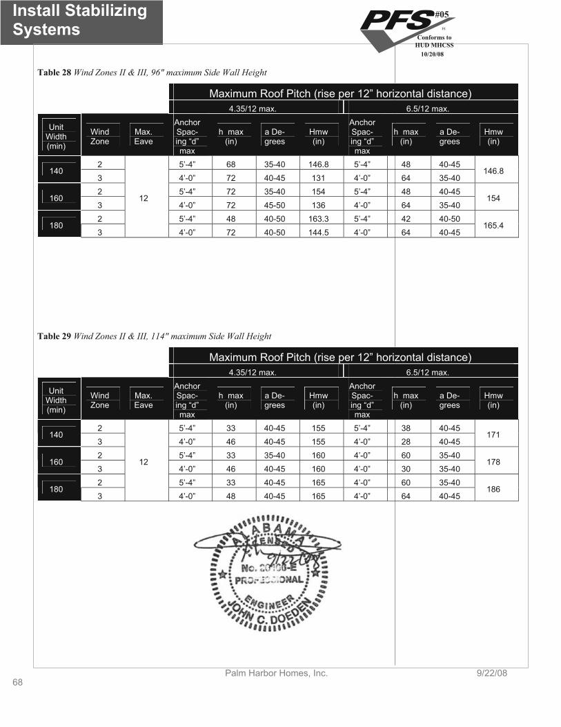
Install Stabilizing Systems
68Palm Harbor Homes, Inc. 9/22/08
Table 28 Wind Zones II & III, 96" maximum Side Wall Height
Maximum Roof Pitch (rise per 12” horizontal distance) 4.35/12 max. 6.5/12 max.
UnitWidth (min)
Wind Zone
Max. Eave
AnchorSpac-ing “d” max
h max (in)
a De-grees
Hmw (in)
AnchorSpac-ing “d” max
h max (in)
a De-grees
Hmw (in)
2 5’-4” 68 35-40 146.8 5’-4” 48 40-45 140
3 4’-0” 72 40-45 131 4’-0” 64 35-40 146.8
2 5’-4” 72 35-40 154 5’-4” 48 40-45 160
3 4’-0” 72 45-50 136 4’-0” 64 35-40 154
2 5’-4” 48 40-50 163.3 5’-4” 42 40-50 180
3
12
4’-0” 72 40-50 144.5 4’-0” 64 40-45 165.4
Table 29 Wind Zones II & III, 114" maximum Side Wall Height
Maximum Roof Pitch (rise per 12” horizontal distance) 4.35/12 max. 6.5/12 max.
UnitWidth (min)
Wind Zone
Max. Eave
AnchorSpac-ing “d” max
h max (in)
a De-grees
Hmw (in)
AnchorSpac-ing “d” max
h max (in)
a De-grees
Hmw (in)
2 5’-4” 33 40-45 155 5’-4” 38 40-45 140
3 4’-0” 46 40-45 155 4’-0” 28 40-45 171
2 5’-4” 33 35-40 160 4’-0” 60 35-40 160
3 4’-0” 46 40-45 160 4’-0” 30 35-40 178
2 5’-4” 33 40-45 165 4’-0” 60 35-40 180
3
12
4’-0” 48 40-45 165 4’-0” 64 40-45 186
#05
Conforms toHUD MHCSS
10/20/08
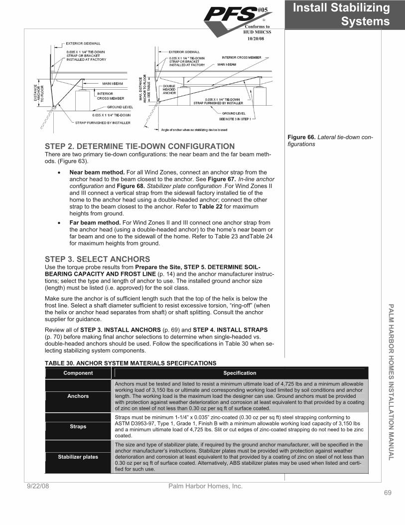
PALM
HA
RB
OR
HO
MES IN
STALLA
TION
MA
NU
AL
Install Stabilizing Systems
9/22/08 Palm Harbor Homes, Inc. 69
Figure 66. Lateral tie-down con-figurationsSTEP 2. DETERMINE TIE-DOWN CONFIGURATION
There are two primary tie-down configurations: the near beam and the far beam meth-ods. (Figure 63).
Near beam method. For all Wind Zones, connect an anchor strap from the anchor head to the beam closest to the anchor. See Figure 67. In-line anchor configuration and Figure 68. Stabilizer plate configuration .For Wind Zones II and III connect a vertical strap from the sidewall factory installed tie of the home to the anchor head using a double-headed anchor; connect the other strap to the beam closest to the anchor. Refer to Table 22 for maximum heights from ground. Far beam method. For Wind Zones II and III connect one anchor strap from the anchor head (using a double-headed anchor) to the home’s near beam or far beam and one to the sidewall of the home. Refer to Table 23 andTable 24for maximum heights from ground.
STEP 3. SELECT ANCHORS Use the torque probe results from Prepare the Site, STEP 5. DETERMINE SOIL-BEARING CAPACITY AND FROST LINE (p. 14) and the anchor manufacturer instruc-tions; select the type and length of anchor to use. The installed ground anchor size (length) must be listed (i.e. approved) for the soil class.
Make sure the anchor is of sufficient length such that the top of the helix is below the frost line. Select a shaft diameter sufficient to resist excessive torsion, “ring-off” (when the helix or anchor head separates from shaft) or shaft splitting. Consult the anchor supplier for guidance.
Review all of STEP 3. INSTALL ANCHORS (p. 69) and STEP 4. INSTALL STRAPS(p. 70) before making final anchor selections to determine when single-headed vs. double-headed anchors should be used. Follow the specifications in Table 30 when se-lecting stabilizing system components.
TABLE 30. ANCHOR SYSTEM MATERIALS SPECIFICATIONS Component Specification
Anchors must be tested and listed to resist a minimum ultimate load of 4,725 lbs and a minimum allowable working load of 3,150 lbs or ultimate and corresponding working load limited by soil conditions and anchor
Anchors length. The working load is the maximum load the designer can use. Ground anchors must be provided with protection against weather deterioration and corrosion at least equivalent to that provided by a coating of zinc on steel of not less than 0.30 oz per sq ft of surface coated.
Straps must be minimum 1-1/4” x 0.035” zinc-coated (0.30 oz per sq ft) steel strapping conforming to ASTM D3953-97, Type 1, Grade 1, Finish B with a minimum allowable working load capacity of 3,150 lbs Straps and a minimum ultimate load of 4,725 lbs. Slit or cut edges of zinc-coated strapping do not need to be zinc coated.
The size and type of stabilizer plate, if required by the ground anchor manufacturer, will be specified in the anchor manufacturer’s instructions. Stabilizer plates must be provided with protection against weather
Stabilizer plates deterioration and corrosion at least equivalent to that provided by a coating of zinc on steel of not less than 0.30 oz per sq ft of surface coated. Alternatively, ABS stabilizer plates may be used when listed and certi-fied for such use.
#05
Conforms toHUD MHCSS
10/20/08

Install Stabilizing Systems
70Palm Harbor Homes, Inc. 9/22/08
STEP 4. INSTALL ANCHORS Before beginning anchor installation, check for obstructions under the home such as piers and frame members that may interfere with the tie down strapping. Check with utility companies to determine the location of underground utilities, such as electrical and phone lines, and water, sewer, and gas pipes that may be buried in potential an-chor locations. Also check for homeowner-installed wires and pipes, such as those connecting exterior lighting or sheds to the home. These must also be avoided.
Grading area around anchors. Anchor heads should not rest in sunken spots. Grade the ground so that water does not collect around anchor heads, but runs away from the anchor and out from under the home. Do not bury anchor heads.
FRAME ANCHORS Frame anchors can be installed in two ways, in-line and against a stabilizer plate. The two methods are discussed below:
In-Line Configuration The in-line configuration (Figure 67) for homes can be used in Wind Zone I only. Typi-cally, in-line anchors are used under high homes where the anchors can be installed from under the home after the home is set. In-line anchors can also be installed before the home is set, however, precisely aligning the anchor with the home both vertically and horizontally is difficult. Using swivel connectors for the strap to beam connection can provide some horizontal flexibility.
To install in-line frame anchors, drive the anchor into the ground at an angle and loca-tion such that a straight line can be drawn from the tip of the anchor through the anchor head and to the connection point on the I-beam (Figure 68).
Sidewall FrameTie-Down Strap
GroundAnchor
MainBeam
Pier
Ground Anchor withStabilizer Plate
MainBeam
Pier
Sidewall FrameTie-Down Strap
Figure 67. In-line anchor configuration
Figure 68. Stabilizer plate configuration
Stabilizer Plate Configuration Stabilizer plate configurations (Figure 68) are suitable for homes in all wind zones. An-chors may be installed after the home is set. A stabilizer device, typically an ABS or metal plate, is used to prevent the top of the anchor from slicing through the soil when the load is applied. Stabilizer plates are available in a variety of widths. Choose the widest plate that can be driven into the soil to maximize resistance to movement. The LAHJ may have stabilizer plate requirements.
Install anchors with stabilizer plates as follows: 1. Locate anchor. Select a location for the anchor under the home but within
six inches of the exterior wall (Figure 69). Avoid locations that will interfere with skirting.
#05
Conforms toHUD MHCSS
10/20/08
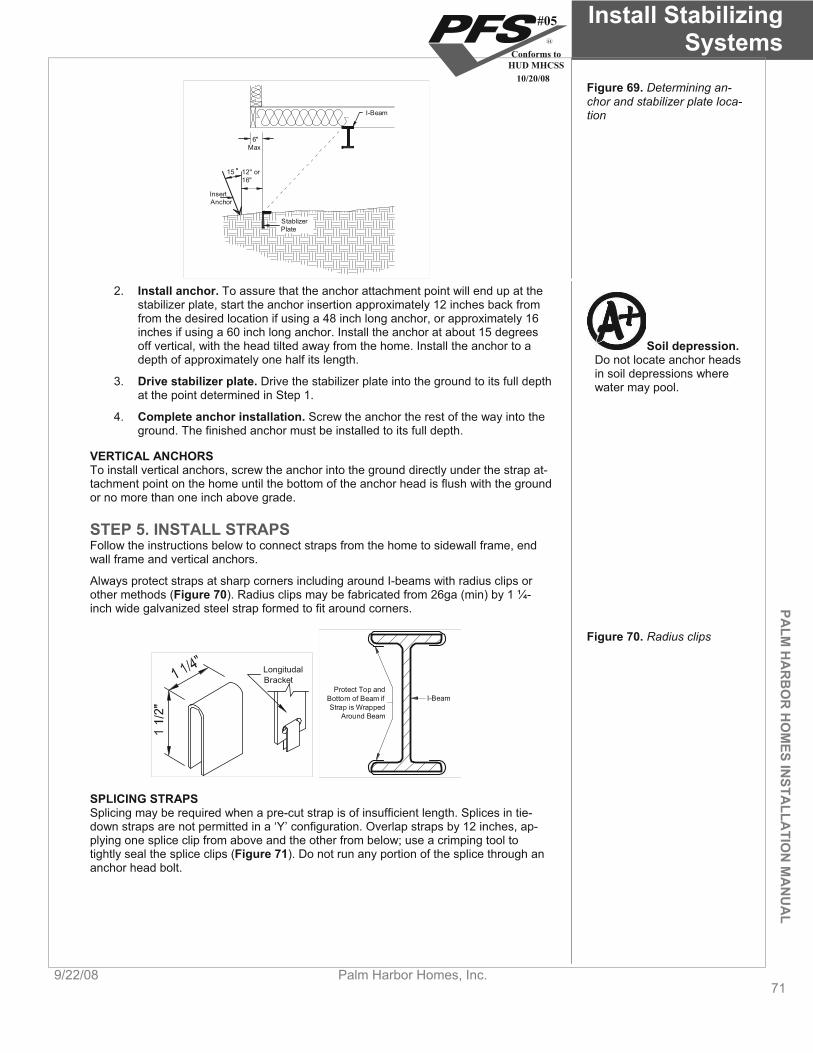
PALM
HA
RB
OR
HO
MES IN
STALLA
TION
MA
NU
AL
Install Stabilizing Systems
9/22/08 Palm Harbor Homes, Inc. 71
I-Beam
StablizerPlate
6"Max
InsertAnchor
15 12" or16"
Figure 69. Determining an-chor and stabilizer plate loca-tion
2. Install anchor. To assure that the anchor attachment point will end up at the stabilizer plate, start the anchor insertion approximately 12 inches back from from the desired location if using a 48 inch long anchor, or approximately 16 inches if using a 60 inch long anchor. Install the anchor at about 15 degrees off vertical, with the head tilted away from the home. Install the anchor to a depth of approximately one half its length.
Soil depression.Do not locate anchor heads in soil depressions where water may pool. 3. Drive stabilizer plate. Drive the stabilizer plate into the ground to its full depth
at the point determined in Step 1.
4. Complete anchor installation. Screw the anchor the rest of the way into the ground. The finished anchor must be installed to its full depth.
VERTICAL ANCHORS To install vertical anchors, screw the anchor into the ground directly under the strap at-tachment point on the home until the bottom of the anchor head is flush with the ground or no more than one inch above grade.
STEP 5. INSTALL STRAPS Follow the instructions below to connect straps from the home to sidewall frame, end wall frame and vertical anchors.
Always protect straps at sharp corners including around I-beams with radius clips or other methods (Figure 70). Radius clips may be fabricated from 26ga (min) by 1 ¼-inch wide galvanized steel strap formed to fit around corners.
Longitudal Bracket
Protect Top andBottom of Beam ifStrap is Wrapped
Around Beam
I-Beam
Figure 70. Radius clips
SPLICING STRAPS Splicing may be required when a pre-cut strap is of insufficient length. Splices in tie-down straps are not permitted in a ‘Y’ configuration. Overlap straps by 12 inches, ap-plying one splice clip from above and the other from below; use a crimping tool to tightly seal the splice clips (Figure 71). Do not run any portion of the splice through an anchor head bolt.
#05
Conforms toHUD MHCSS
10/20/08

Install Stabilizing Systems
72Palm Harbor Homes, Inc. 9/22/08
Approx. 12"
Strap
Apply SpliceClips In Directionof Arrows
'Y' SpliceNotPermittedNO
Figure 71. Tie-down strap splice
SIDEWALL FRAME ANCHORS Install straps to sidewall frame anchors as follows:
1. Connect strap to home. Connect one end of the strap to the home connec-tion point using approved buckles or clips (swivel or hook clip preferred).
Wrap strap around mainbeam
1 Connect hook to top ofmain beam and connectother end of strap toanchor head.
2
To GroundAnchor Head
Figure 72. Strap to beam connection
Strap to beam connection. Regardless of the strap supplier’s recommenda-tions, the strap must be connected to the top of the main beam to prevent damage to the structure.
2. Connect strap to anchor. Connect the other end of the strap to the split bolt in the anchor. Leave enough strap length to be able to make at least three, but no more than five complete turns around the bolt before it becomes tight (approximately 2 1/2 inches per turn or 7 1/2 to 13 inches total). Fewer than three turns and the strap may not hold onto the bolt when force is applied. Conversely, more than five turns may not fit within the U-channel of the an-chor head. Follow the procedure outlined in Figure 73.
#05
Conforms toHUD MHCSS
10/20/08

PALM
HA
RB
OR
HO
MES IN
STALLA
TION
MA
NU
AL
Install Stabilizing Systems
9/22/08 Palm Harbor Homes, Inc. 73
Once fully tensioned, align thesquare neck of the bolt with thesquare recess in the anchor headand tighten the hex nut. This willdraw the two together and lock thesystem into final position.
7
Using a 15/16" socket or open endwrench, rotate clockwise, wrappingthe strap around the tension bolt.
5Place the strap through the slottedshank of the tension bolt and bendup to 90°.
4
Once tensioned to the point thatcounter-clockwise resistanceappears, use a 5/8" open endwrench to hold the square neckwhile repositioning the 15/16"tensioning wrench to continuetensioning. Repeat as required.
6
Insert the tension bolt into theanchor head and loosely attachthe hex nut.
3
If approved by the manufacturer,double head anchors may be usedfor both diagonal and verticaltie-down strap tensioning. Tensionthe diagonal tie-down strap first.Follow Steps 3 through 7 to installstraps to anchor head.
Figure 73. Procedure for connecting the strap to frame and anchor
3. Pretension anchor. For anchors with stabilizer plates, pretension the anchor by pulling it up to the stabilizer plate using the strap and take-up bolt to move the anchor head. Continue pulling the strap until the plate moves a small amount (about 1/2 inch). This is called packing the plate and it will yield the strongest resistance (the bottom of the anchor head should be maximum 1/4 inch above the top of the stabilizer plate).
Anchor head location. As the anchor is pulled up to meet the stabilizer plate, the head of the anchor will rise. In its final position, the bottom of the anchor head should be no more than 1/4 inch above the top of the stabilizer plate.
END WALL FRAME ANCHORS Attach straps to the bracket welded by the manufacturer to the frame (Figure 74). If no brackets have been installed, use approved beam clamps designed specifically for this purpose, available from anchor suppliers. Connect straps to anchors following same procedure as for sidewall frame anchors.
Figure 74. End wall frame anchor attachment method
#05
Conforms toHUD MHCSS
10/20/08
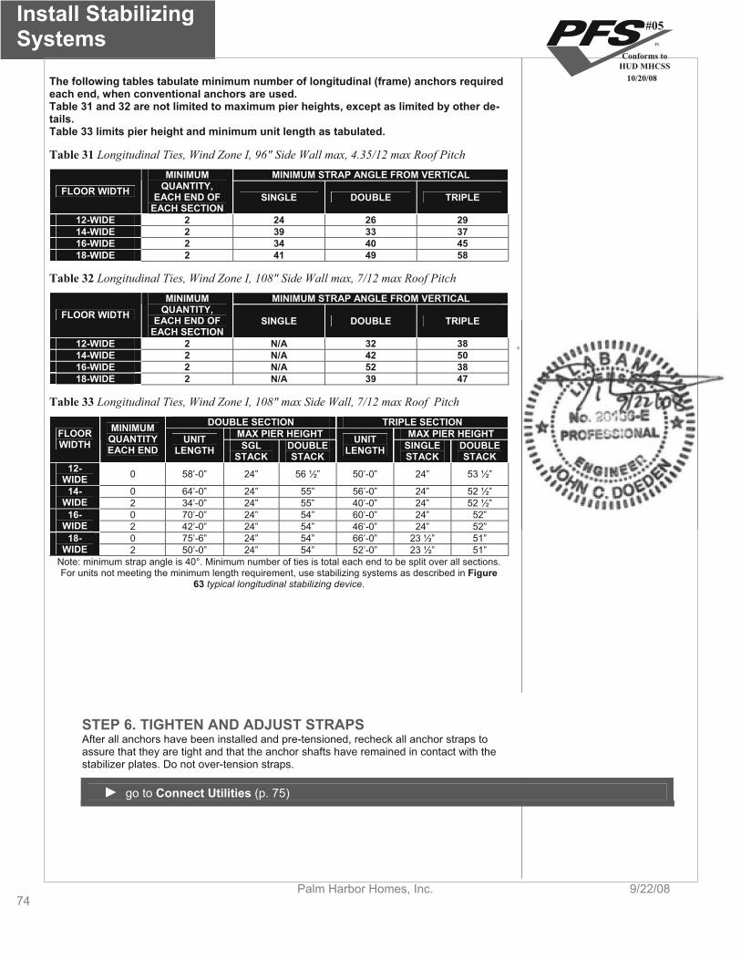
Install Stabilizing Systems
74Palm Harbor Homes, Inc. 9/22/08
The following tables tabulate minimum number of longitudinal (frame) anchors required each end, when conventional anchors are used. Table 31 and 32 are not limited to maximum pier heights, except as limited by other de-tails.Table 33 limits pier height and minimum unit length as tabulated.
Table 31 Longitudinal Ties, Wind Zone I, 96" Side Wall max, 4.35/12 max Roof PitchMINIMUM STRAP ANGLE FROM VERTICAL MINIMUM
QUANTITY, FLOOR WIDTH EACH END OF SINGLE DOUBLE TRIPLEEACH SECTION
12-WIDE 2 24 26 2914-WIDE 2 39 33 3716-WIDE 2 34 40 4518-WIDE 2 4 1 49 58
Table 32 Longitudinal Ties, Wind Zone I, 108" Side Wall max, 7/12 max Roof PitchMINIMUM STRAP ANGLE FROM VERTICAL MINIMUM
QUANTITY, FLOOR WIDTH EACH END OF SINGLE DOUBLE TRIPLEEACH SECTION
12-WIDE 2 N/A 32 3814-WIDE 2 N/A 42 5016-WIDE 2 N/A 52 3818-WIDE 2 N/ A 39 47
Table 33 Longitudinal Ties, Wind Zone I, 108" max Side Wall, 7/12 max Roof PitchDOUBLE SECTION TRIPLE SECTION
MAX PIER HEIGHT MAX PIER HEIGHT MINIMUMFLOOR WIDTH QUANTITY
EACH END UNIT
LENGTH SGL STACK
UNITDOUBLE STACK LENGTH SINGLE DOUBLE
STACK STACK 12- 0 58’-0” 24” 56 ½” 50’-0” 24” 53 ½” WIDE
0 64’-0” 24” 55” 56’-0” 24” 52 ½” 14-WIDE 2 34’-0” 24” 55” 40’-0” 24” 52 ½”
0 70’-0” 24” 54” 60’-0” 24” 52”16-WIDE 2 42’-0” 24” 54” 46’-0” 24” 52”
0 75’-6” 24” 54” 66’-0” 23 ½” 51”18-WIDE 2 50’-0” 24” 54” 52’-0” 23 ½” 51”
Note: minimum strap angle is 40°. Minimum number of ties is total each end to be split over all sections. For units not meeting the minimum length requirement, use stabilizing systems as described in Figure
63 typical longitudinal stabilizing device.
STEP 6. TIGHTEN AND ADJUST STRAPS After all anchors have been installed and pre-tensioned, recheck all anchor straps to assure that they are tight and that the anchor shafts have remained in contact with the stabilizer plates. Do not over-tension straps.
go to Connect Utilities (p. 75)
#05
Conforms toHUD MHCSS
10/20/08
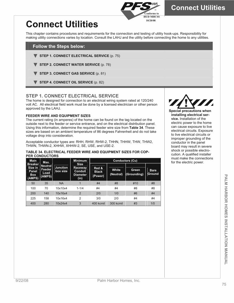
PALM
HA
RB
OR
HO
MES IN
STALLA
TION
MA
NU
AL
Connect Utilities
9/22/08 Palm Harbor Homes, Inc. 75
Connect Utilities This chapter contains procedures and requirements for the connection and testing of utility hook-ups. Responsibility for making utility connections varies by location. Consult the LAHJ and the utility before connecting the home to any utilities.
Follow the Steps below:
STEP 1. CONNECT ELECTRICAL SERVICE (p. 75)
STEP 2. CONNECT WATER SERVICE (p. 78)
STEP 3. CONNECT GAS SERVICE (p. 81)
STEP 4. CONNECT OIL SERVICE (p. 82)
STEP 1. CONNECT ELECTRICAL SERVICE The home is designed for connection to an electrical wiring system rated at 120/240 volt AC. All electrical field work must be done by a licensed electrician or other person approved by the LAHJ.
Special precautions when installing electrical ser-vice. Installation of the electric power to the home can cause exposure to live electrical circuits. Exposure to live electrical circuits or improper grounding of the conductor in the panel board may result in severe shock or possible electro-cution. A qualified installer must make the connections for the electric power.
FEEDER WIRE AND EQUIPMENT SIZES The current rating (in amperes) of the home can be found on the tag located on the outside next to the feeder or service entrance, and on the electrical distribution panel. Using this information, determine the required feeder wire size from Table 34. These sizes are based on an ambient temperature of 86 degrees Fahrenheit and do not take voltage drop into consideration.
Acceptable conductor types are: RHH, RHW, RHW-2, THHN, THHW, THW, THW2, THWN, THWN-2, XHHW, XHHW-2, SE, USE, and USE-2.
TABLE 34. ELECTRICAL FEEDER WIRE AND EQUIPMENT SIZES FOR COP-PER CONDUCTORS
Conductors (Cu)MainBreakerSize in PanelBox
(AMPS)
Max.NeutralFeederLoad
(AMPS)
MinimumSize
Junction Raceway Red & White Green Barebox size Conduit BlackGround Diameter
(in)(Power) (Neutral) (Grounding)
50 35 NA 1 #4 #8 #10 #8100 70 10x10x4 1-1/4 #4 #4 #8 #8200 140 10x16x4 2 2/0 1/0 #6 #4225 158 10x16x4 2 3/0 2/0 #4 #4400 280 10x24x4 3 400 kcmil 300 kcmil #3 1/0
#05
Conforms toHUD MHCSS
10/20/08
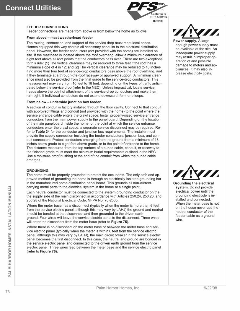
Connect Utilities
76Palm Harbor Homes, Inc. 9/22/08
PALM
HA
RB
OR
HO
MES
INST
ALL
ATI
ON
MA
NU
AL
FEEDER CONNECTIONS Feeder connections are made from above or from below the home as follows:
From above – mast weatherhead feeder Power supply. A large
enough power supply must be available at the site. An inadequate power supply may result in improper op-eration of and possible damage to motors and ap-pliances. It may also in-crease electricity costs.
The routing, connection, and support of the service drop must meet local codes. Homes equipped this way contain all necessary conduits to the electrical distribution panel. However, the feeder conductors (not provided with the home) are installed on site. If the masthead is located above the roof overhang, allow a minimum clearance of eight feet above all roof points that the conductors pass over. There are two exceptions to this rule: (1) The vertical clearance may be reduced to three feet if the roof has a minimum slope of 4 in 12; and (2) The vertical clearance may be reduced to 18 inches if no more than four feet of service-drop conductors pass above the roof overhang, and if they terminate at a through-the-roof raceway or approved support. A minimum clear-ance must also be provided from the final grade to the service-drop conductors. This measurement may vary from 10 feet to 18 feet, depending on the types of traffic antici-pated below the service drop (refer to the NEC). Unless impractical, locate service heads above the point of attachment of the service-drop conductors and make them rain-tight. If individual conductors do not extend downward, form drip loops.
From below – underside junction box feederA section of conduit is factory installed through the floor cavity. Connect to that conduit with approved fittings and conduit (not provided with the home) to the point where the service entrance cable enters the crawl space. Install properly-sized service entrance conductors from the main power supply to the panel board. Depending on the location of the main panelboard inside the home, or the point at which the service entrance conductors enter the crawl space, a separate service disconnect may be required. Re-fer to Table 34 for the conductor and junction box requirements. The installer must provide the supply connection including the feeder conductors, junction box, and con-duit connectors. Protect conductors emerging from the ground from a minimum of 18 inches below grade to eight feet above grade, or to the point of entrance to the home. The distance measured from the top surface of a buried cable, conduit, or raceway to the finished grade must meet the minimum burial requirements outlined in the NEC. Use a moisture-proof bushing at the end of the conduit from which the buried cable emerges.
GROUNDINGThe home must be properly grounded to protect the occupants. The only safe and ap-proved method of grounding the home is through an electrically-isolated grounding bar in the manufactured home distribution panel board. This grounds all non-current-carrying metal parts to the electrical system in the home at a single point.
Grounding the electrical system. Do not provide electrical power until the grounding electrode is in-stalled and connected. When the meter base is not on the house never use the neutral conductor of the feeder cable as a ground wire.
Each neutral conductor must be connected to the system grounding conductor on the the supply side of the main disconnect in accordance with Articles 250.24, 250.26, and 250.28 of the National Electrical Code, NFPA No. 70-2005. Where the meter base has a disconnect (typically when the meter is more than 6 feet from the service electric panel, although this may vary by LAHJ) the ground and neutral should be bonded at that disconnect and then grounded to the driven earth ground. Four wires will leave the service electric panel to the disconnect. Three wires will enter the disconnect from the meter base (refer to Figure 75).Where there is no disconnect on the meter base or between the meter base and ser-vice electric panel (typically when the meter is within 6 feet from the service electric panel, although this may vary by LAHJ), the main circuit breaker in the service electric panel becomes the first disconnect. In this case, the neutral and ground are bonded in the service electric panel and connected to the driven earth ground from the service electric panel. Three wires lead between the meter base and the service electric panel (refer to Figure 76).
#05
Conforms toHUD MHCSS
10/20/08
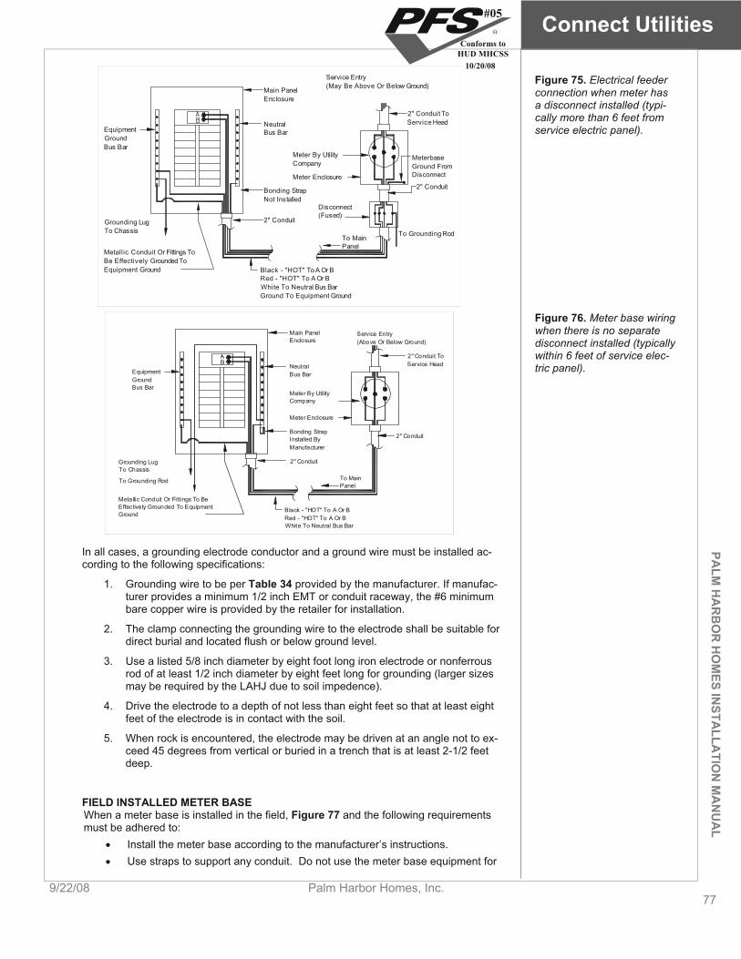
PALM
HA
RB
OR
HO
MES IN
STALLA
TION
MA
NU
AL
Connect Utilities
9/22/08 Palm Harbor Homes, Inc. 77
EquipmentGroundBus Bar
Grounding LugTo Chassis
Metallic Conduit Or Fittings ToBe Effectively Grounded ToEquipment Ground Black - "HOT" To A Or B
Red - "HOT" To A Or BWhite To Neutral Bus BarGround To Equipment Ground
Main PanelEnclosure
NeutralBus Bar
Service Entry(May Be Above Or Below Ground)
2" Conduit ToService Head
MeterbaseGround FromDisconnect
2" Conduit
To Grounding RodTo MainPanel
Disconnect(Fused)
2" Conduit
Bonding StrapNot Installed
Meter By UtilityCompany
Meter Enclosure
Figure 75. Electrical feeder connection when meter has a disconnect installed (typi-cally more than 6 feet from service electric panel).
EquipmentGroundBus Bar
Grounding LugTo Chassis
To Grounding Rod
Metallic Conduit Or Fittings To BeEffectively Grounded To EquipmentGround
Black - "HOT" To A Or BRed - "HOT" To A Or BWhite To Neutral Bus Bar
2" Conduit
2" Conduit ToService Head
Service Entry(Above Or Below Ground)
Main PanelEnclosure
NeutralBus Bar
Meter By UtilityCompany
Meter Enclosure
Bonding StrapInstalled ByManufacturer
2" Conduit
To MainPanel
Figure 76. Meter base wiring when there is no separate disconnect installed (typically within 6 feet of service elec-tric panel).
In all cases, a grounding electrode conductor and a ground wire must be installed ac-cording to the following specifications:
1. Grounding wire to be per Table 34 provided by the manufacturer. If manufac-turer provides a minimum 1/2 inch EMT or conduit raceway, the #6 minimum bare copper wire is provided by the retailer for installation.
2. The clamp connecting the grounding wire to the electrode shall be suitable for direct burial and located flush or below ground level.
3. Use a listed 5/8 inch diameter by eight foot long iron electrode or nonferrous rod of at least 1/2 inch diameter by eight feet long for grounding (larger sizes may be required by the LAHJ due to soil impedence).
4. Drive the electrode to a depth of not less than eight feet so that at least eight feet of the electrode is in contact with the soil.
5. When rock is encountered, the electrode may be driven at an angle not to ex-ceed 45 degrees from vertical or buried in a trench that is at least 2-1/2 feet deep.
FIELD INSTALLED METER BASEWhen a meter base is installed in the field, Figure 77 and the following requirements must be adhered to:
Install the meter base according to the manufacturer’s instructions. Use straps to support any conduit. Do not use the meter base equipment for
#05
Conforms toHUD MHCSS
10/20/08

Connect Utilities
78Palm Harbor Homes, Inc. 9/22/08
PALM
HA
RB
OR
HO
MES
INST
ALL
ATI
ON
MA
NU
AL
support. Use exterior equipment and enclosures listed as weatherproof and entrance
conductors listed for wet locations. The grounding bar may be installed separate from the neutral bar for pur-
poses of testing the electrical system. The grounding bar may be isolated during the electrical check and re-
attached, after the tests are completed. Check with the local electrical utility to verify meter base requirements and lo-
cations and distances for the main panel and meter box. The field installed meter base enclosure must be installed in accordance with
its listing. Fasten securely to exterior wall studs and provide for a weather-tight seal.
Check the local code for any requirements regarding the location of the meter base.
Meter
Exterior Wall
Meter Enclosure
1/4" Air SpaceBetween MeterEnclosure AndExterior Wall
Figure 77. Meter base clear-ances.
STEP 2. CONNECT WATER SERVICE CONNECTIONTo connect the home’s water system to the water source, identify the water inlet lo-cated under the home (usually below the water heater compartment or utility room) and follow the procedure described below (refer to Figure 78):
Selecting heat tape. Useonly pipe-heating cable (tape) listed for manufac-tured homes, and install it in accordance with the ca-ble (tape) manufacturer in-stallation instructions.
1. Flush pipe. Flush field-installed water piping free of all debris prior to connec-tion to the home’s water inlet.
2. Clean threads. Ensure that pipe threads are clean. 3. Install pressure-reducing valve. If the local water supply exceeds 80 psi in-
stall a pressure-reducing valve. Maximum water pressure.
The water system for the home was designed for a maximum inlet pressure of 80 psi.
4. Connect valve. Install a main shut-off valve between the water supply and the inlet on the home. Locate the riser for the shutoff valve underneath or ad-jacent to the home. Select a full flow gate or ball shutoff valve, or equivalent valve. To prevent the possibility of fresh water contamination install an anti-siphon valve on all field installed exterior faucets.
#05
Conforms toHUD MHCSS
10/20/08

PALM
HA
RB
OR
HO
MES IN
STALLA
TION
MA
NU
AL
Connect Utilities
9/22/08 Palm Harbor Homes, Inc. 79
Factory-InstalledWater Pipe
Optional Hose Bib(Not Supplied)Connect To 'T'Here For WaterSystem Test
Locate Water RiserUnderneath orAdjacent to Home
Mandatory Shut-OffValve (Not Supplied)
ServiceConnection(Not Supplied)
Figure 78. Water system connection
5. Install water heater discharge drain. Inspect the drain opening on the water heater to ensure that it is clear of any obstruction. If the home is to be installed on a basement or enclosed crawlspace, install drain pipe connecting the dis-charge from the water heater temperature and pressure relief valve to the out-side or to a sump. Using check
valves. Install a check valve on the water inlet to prevent water system drainage in the event of a loss of water pressure from the source. Such pressure loss could cause the water heater to drain, exposing the heating elements of electric water heaters caus-ing them to fail.
6. Install water heater drip pan drain. Assure that the drain for the water heater drip pan does not terminate under the home. Using the materials pro-vided and the accompanying instructions run a drain line from the water heater drip pan through the wall or floor to the exterior of the crawl space. Terminate the line between six and 24 inches above grade. (Figure 79). Make the termination point rodent proof.
Figure 79. Water heater drip pan and drain
DripPan
WaterHeater
Floor
ExteriorWall
Factory-InstalledDrain Pipe
BottomBoard
CrawlspacePerimeterEnclosure
Field-InstalledDrain Pipe
6" to 24"
#05
Conforms toHUD MHCSS
10/20/08
Connect Utilities
80Palm Harbor Homes, Inc. 9/22/08
PALM
HA
RB
OR
HO
MES
INST
ALL
ATI
ON
MA
NU
AL
7. Insulate. In areas subject to freezing temperatures, protect with insulation or heat tape pipes, valves and pressure reducers that are exposed to the out-doors; and pipes in water heater compartments with non-insulated doors. Connect heat tape to the electrical outlet under the home near the water sup-ply inlet. Selecting heat tape. Use
only pipe-heating cable (tape) listed for manufac-tured homes, and install it in accordance with the ca-ble (tape) manufacturer in-stallation instructions.
TESTINGAfter testing the electrical system and connecting the water lines check the water sys-tem for leaks using one of the procedures described below. Before testing, close all water faucets, spigots, and toilet-tank float valves.
Hydrostatic (preferred): Testing water lines. Only
use pneumatic (air) testing when hydrostatic testing is not practical. Air under pressure is explosive. Ex-ercise extreme caution and notify all site personnel of the test. Wear protective eyewear and take precau-tions to prevent impact damage to the system while the test is in progress. Do not pneumatically test CPVC systems. Pneumati-cally test Flow Guard Gold systems only at low pres-sure levels (20 psi or less).
1. Bypass water heater. Bypass the hot water heater by disconnecting the hot outlet and cold inlet water lines from the water heater and joining them to-gether. This will protect the hot water tank from damage and protect those in-volved in the test from possible injury.
2. Fill water heater. Confirm that the water heater tank is full of water. 3. Pressurize system. Connect a hydrostatic pump, valve, and gauge to the lo-
cation shown in Figure 78. Pressurize the system with water at 100 psi, and then isolate it from the pressure source. Bleed all air from the highest and far-thest points in the system.
4. Hold pressure. Monitor the pressure for at least 15 minutes. 5. Fix leaks. If the pressure drops below 100 psi, locate and correct any leaks
by cutting out and discarding bad pipe sections or joints and installing new pipe or joints with couplings.
6. Repeat. Repeat the test until all leaks have been eliminated.
Pneumatic: Pressurizing water lines.
When pressurizing the wa-ter system, connect the pump to a location above a closed shut-off valve so as not to introduce pressure into the municipal water supply.
1. Bypass water heater. Bypass the hot water heater by disconnecting the hot outlet and cold inlet water lines from the water heater and joining them to-gether. This will protect the hot water tank from damage and protect those in-volved in the test from possible injury.
2. Pressurize system. Connect an air pump and pressure gauge to the water inlet, pressurize the system to 100 psi and isolate the pressure source from the system.
3. Hold pressure. Monitor the pressure for least 15 minutes. If the pressure drops below 100 psi, locate any leaks by applying soapy water to the connec-tions and looking for bubbles.
4. Fix leaks. Correct any leaks by cutting out and discarding bad pipe sections or joints and installing new pipe or joints with couplings.
5. Retest. Repeat the procedure until all leaks have been eliminated. 6. Restore connections. Reconnect the water heater and the water supply.
FREEZE PROTECTION FOR UNOCCUPIED HOMES If the home is to be left unheated in cold weather, protect water lines from freezing as follows:
1. Disconnect supply. Turn off the water supply and disconnect the water sup-ply inlet.
2. Drain water heater. Turn off the water heater; if necessary, attach a hose to the valve to direct water away from under the home, open the drain valve and drain the tank completely.
3. Drain faucets. Open all faucets throughout the home (including the laundry area if plumbed, and any exterior faucets) and let them drain completely.
4. Drain toilets. Flush toilets and drain water tanks completely. 5. Close faucets. Close all water faucets with the exception of one. 6. Connect compressor. Connect a maximum of 30 psi air supply to the water
inlet connection using a low pressure compressor. 7. Open faucets. With the air supply on the system, open one faucet at a time
throughout the home.
#05
Conforms toHUD MHCSS
10/20/08
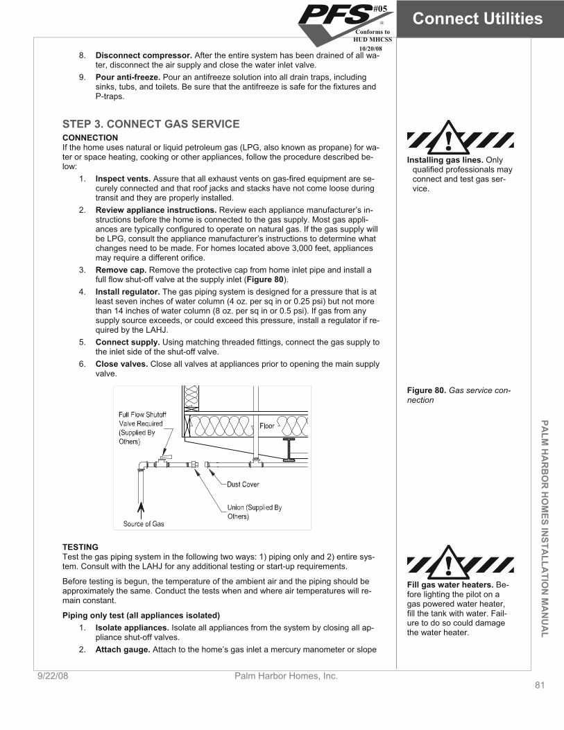
PALM
HA
RB
OR
HO
MES IN
STALLA
TION
MA
NU
AL
Connect Utilities
9/22/08 Palm Harbor Homes, Inc. 81
8. Disconnect compressor. After the entire system has been drained of all wa-ter, disconnect the air supply and close the water inlet valve.
9. Pour anti-freeze. Pour an antifreeze solution into all drain traps, including sinks, tubs, and toilets. Be sure that the antifreeze is safe for the fixtures and P-traps.
STEP 3. CONNECT GAS SERVICE CONNECTIONIf the home uses natural or liquid petroleum gas (LPG, also known as propane) for wa-ter or space heating, cooking or other appliances, follow the procedure described be-low:
Installing gas lines. Only qualified professionals may connect and test gas ser-vice.
1. Inspect vents. Assure that all exhaust vents on gas-fired equipment are se-curely connected and that roof jacks and stacks have not come loose during transit and they are properly installed.
2. Review appliance instructions. Review each appliance manufacturer’s in-structions before the home is connected to the gas supply. Most gas appli-ances are typically configured to operate on natural gas. If the gas supply will be LPG, consult the appliance manufacturer’s instructions to determine what changes need to be made. For homes located above 3,000 feet, appliances may require a different orifice.
3. Remove cap. Remove the protective cap from home inlet pipe and install a full flow shut-off valve at the supply inlet (Figure 80).
4. Install regulator. The gas piping system is designed for a pressure that is at least seven inches of water column (4 oz. per sq in or 0.25 psi) but not more than 14 inches of water column (8 oz. per sq in or 0.5 psi). If gas from any supply source exceeds, or could exceed this pressure, install a regulator if re-quired by the LAHJ.
5. Connect supply. Using matching threaded fittings, connect the gas supply to the inlet side of the shut-off valve.
6. Close valves. Close all valves at appliances prior to opening the main supply valve.
Figure 80. Gas service con-nection
TESTINGTest the gas piping system in the following two ways: 1) piping only and 2) entire sys-tem. Consult with the LAHJ for any additional testing or start-up requirements.
Before testing is begun, the temperature of the ambient air and the piping should be approximately the same. Conduct the tests when and where air temperatures will re-main constant.
Fill gas water heaters. Be-fore lighting the pilot on a gas powered water heater, fill the tank with water. Fail-ure to do so could damage the water heater.
Piping only test (all appliances isolated) 1. Isolate appliances. Isolate all appliances from the system by closing all ap-
pliance shut-off valves. 2. Attach gauge. Attach to the home’s gas inlet a mercury manometer or slope
#05
Conforms toHUD MHCSS
10/20/08
Connect Utilities
82Palm Harbor Homes, Inc. 9/22/08
PALM
HA
RB
OR
HO
MES
INST
ALL
ATI
ON
MA
NU
AL
gauge calibrated in increments of not more than 1/10 lb. 3. Pressurize system. Using an air compressor, pressurize the system with
compressed air to three psi and isolate the pressure source from the system. 4. Monitor pressure. Monitor the pressure for at least 10 minutes. 5. Check for leaks. If pressure drops below three psi, check for leaks by apply-
ing a non-corrosive, ammonia-free gas leak detection fluid to the joints at all valves, appliance connections, and crossover connections (do not use dish washing detergents, soap, or other household chemicals). If bubbles form, tighten the connection and recheck.
6. Repair leaks. If leaks persist, replace defective pipes or fittings with sound material and retest.
7. Release pressure. Release pressure and open all appliance shut-off valves. 8. Rinse connections. Thoroughly rinse all tested connections with water to
remove leak detection fluid.
Entire system test (with appliances) 1. Close appliances. Close all gas equipment controls and pilot light valves ac-
cording to the individual gas equipment manufacturer’s instructions. 2. Open valves. Assure that gas shut-off valves for all gas equipment are in the
open position. 3. Attach gauge. Attach to the home’s gas inlet a pressure gauge calibrated in
ounces. 4. Pressurize system. Pressurize the system with compressed air to six to eight
ounces (3/8 to 1/2 psi, or 10 to 14 inches of water column). 5. Check for leaks. Check for leaks as described above in step 4 of the Piping
only test. Replace defective pipes or fittings with sound material and re-test. 6. Rinse connections. Thoroughly rinse all tested connections with water to
remove leak detection fluid.
GAS APPLIANCE START-UP Open the shut-off valve for each appliance and adjust the burners according to the ap-pliance manufacturer’s instructions. Verify that the furnace and water heater thermo-stats are operating properly and set them to the desired temperatures.
STEP 4. CONNECT OIL SERVICE Homes that are equipped with oil burning furnaces must have oil supply piping installed and tested on site by a qualified professional in accordance with NFPA 31, Standard for the Installation of Oil Burning Equipment, 2001 or the requirements of the LAHJ, whichever is more stringent. The home manufacturer does not supply oil piping or tanks.
Testing oil tanks. All oil storage tank and piping in-stallations and tests must meet all applicable local regulations and should be made only by experienced, qualified personnel.
OIL CONNECTION Consult the furnace manufacturer’s instructions for proper pipe-sizing and installation procedures. Where piping is run through the bottom of the home, ensure all holes in the bottom board are sealed tight with foam, mastic, and/or tape specially made for that purpose and made rodent proof.
When equipping the home with an oil storage tank, comply with the following: Install the pipe with a gradual slope toward the fill end or drain plug (if so
equipped) to facilitate pumping or draining of water and sludge. Provide a readily accessible approved manual shut-off valve at the outlet, in-
stalled to close against the supply. Equip the tank with an approved oil filter or strainer located downstream from
the tank shut-off valve. Use a filter or strainer containing a sump with a drain to trap water.
Equip under ground tanks with a filler neck extending one foot above grade and a minimum 1-1/4 inch diameter vent pipe extending at least two feet above grade.
Locate the tank to be accessible for service and inspection, and safe from fire
#05
Conforms toHUD MHCSS
10/20/08

PALM
HA
RB
OR
HO
MES IN
STALLA
TION
MA
NU
AL
Connect Utilities
9/22/08 Palm Harbor Homes, Inc. 83
and other hazards. If the tank is located inside a compartment of the home, provide ventilation at
the bottom of the compartment to permit diffusion of vapors. If the tank is fixed to the home, provide for filling and draining from the outside.
Insulate interior tanks from the structural members of the home. Provide tanks so installed with an outside fill and vent pipe and an approved liquid level gauge.
Install tanks that feed vaporizing type oil furnaces so that oil flows by gravity. To achieve efficient gravity flow, make sure that the bottom of the tank is at least 18 inches above the furnace oil control level.
Tanks for gun type oil furnaces (these furnaces include a fuel pump) may be installed above or below ground.
OIL SYSTEM TESTING Before operating the system, fill the tank to capacity with the fuel to be burned and visually check all joints in the system for leakage. Replace (do not repair) parts that leak.
go to Prepare Appliances and Equipment (p. 84)
#05
Conforms toHUD MHCSS
10/20/08
Prepare Appliances and Equipment
84Palm Harbor Homes, Inc. 9/22/08
Prepare Appliances and Equipment This chapter provides instructions for installing and/or preparing appliances and other equipment. While the items below can be completed in any order, the last item, CONDUCT ELECTRICAL TEST, must be done last.
Follow the Steps below:
INSTALL AIR CONDITIONER 84) OR HEAT PUMP (p.
PREPARE HEATING SYSTEM (p. 85)
INSTALL REMOTE HEATING AND COOLING EQUIPMENT (p. 85)
PREPARE VENTILATION SYSTEM (p. 86)
PREPARE FUEL-BURNING WATER HEATER (p. 86)
PREPARE CLOTHES DRYER (p. 87)
PREPARE SMOKE ALARMS (p. 87)
PREPARE FIREPLACES (p. 88)
PREPARE KITCHEN AND BATH APPLIANCES / FIXTURES (p. 90)
INSTALL EXTERIOR LIGHTING (p. 91)
INSTALL CEILING FANS AND LIGHTING (p. 91)
TEST ELECTRICAL SYSTEM (p. 93)
INSTALL AIR CONDITIONER OR HEAT PUMP (if applicable) CENTRAL UNITS Install split system or unitary central air conditioners and/or heat pumps as follows:
PALM
HA
RB
OR
HO
MES
INST
ALL
ATI
ON
MA
NU
AL 1. Check suitability. Check the home’s Comfort Cooling Certificate (may be in-
cluded with the data plate) to confirm that the home is suitable for installation of central air. If so, note the air distribution system’s rated duct capacity (BTU/hr), any equipment sizing guidance provided by the manufacturer and information provided to calculate the home’s heat gain.
Use listed appliances. All applicable appliances must be listed or certified by a nationally recognized test-ing agency for the applica-tion for which the unit is in-tended and installed in ac-cordance with the terms of its listing or certification.
2. Select equipment. Select equipment with a rated heating capacity (BTU/hr) not exceeding the maximum indicated on the home’s data plate and a rated cooling capacity sized in accordance with Chapter 28 of the 1997 ASHRAE Handbook of Fundamentals or ACCA Manual J, Residential Cooling Load, 8th edition. Information needed to calculate the home’s heat gain can be found on the home’s comfort cooling certificate. Choose equipment with a minimum cir-cuit amperage (found on the equipment rating plate) no greater than the branch circuit rating of the exterior air conditioning receptacle (indicated on the adjacent tag), if present.
Properly sizing equipment.Oversized cooling equip-ment can lower energy effi-ciency, reduce comfort, shorten equipment life, and may cause moisture prob-lems in the home (including potentially damaging the home’s structure). Sizing guidance is provided by the Manufactured Housing Re-search Alliance Cooling Equipment Sizing Guide-
3. Install A-coil. When installing a cooling A-coil in a down-flow furnace that in-corporates a fresh air intake duct, position the duct in the furnace cavity ac-cording to the furnace manufacturer’s instructions (Figure 81). For electric down-flow furnaces, trim the ventilation duct as needed to allow installation of the A-coil and secure the duct to the wall of the compartment or to the top of the A-coil. Do not restrict the flex duct opening; allow the duct insulation to contact the A-coil, or allow the duct to become kinked, restricted, or config-
#05
Conforms toHUD MHCSS
10/20/08
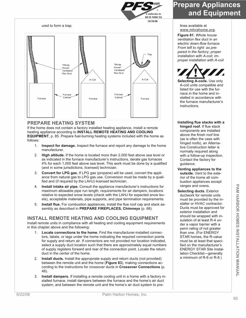
PAM
HA
RB
OR
HO
MES IN
STALLA
TION
MA
NU
AL
Prepare Appliances and Equipment
9/22/08 Palm Harbor Homes, Inc. 85
ured to form a trap. lines available at www.mhrahome.org.
Figure 81. Whole house ventilation flex duct in an electric down-flow furnace. From left to right: as pre-pared in the factory; proper installation with A-coil; im-proper installation with A-coil
FurnaceCabinet
"WholeHouse"VentilationFlex Duct
FurnaceCabinet
"WholeHouse"VentilationFlex Duct
Furnace Furnace Furnace
A-Coil A-Coil
Trap
Selecting A-coils. Use only A-coil units compatible and listed for use with the fur-nace in the home and in-stalled in accordance with the furnace manufacturer’s instructions.
PREPARE HEATING SYSTEM Installing flue stacks with a hinged roof. If flue stack components are installed above the finish roof line (as is often the case with hinged roofs), an Alterna-tive Construction letter is normally required along with a follow-up inspection. Contact the factory for guidance.
If the home does not contain a factory installed heating appliance, install a remote heating appliance according to INSTALL REMOTE HEATING AND COOLING EQUIPMENT, p. 85. Prepare fuel-burning heating systems included with the home as follows:
1. Inspect for damage. Inspect the furnace and report any damage to the home manufacturer.
2. High altitude. If the home is located more than 2,000 feet above sea level or as indicated in the furnace manufacturer’s instructions, derate gas furnaces 4% for each 1,000 feet above sea level. This work must be done by a qualified (and in some jurisdictions, licensed) technician. Venting appliances to the
outside. Vent to the exte-rior of the home all com-bustion appliances except ranges and ovens.
3. Convert for LPG gas. If LPG gas (propane) will be used, convert the appli-ance from natural gas to LPG gas use. Conversion must be made by a quali-fied and (if required by the LAHJ) licensed technician.
4. Install intake air pipe. Consult the appliance manufacturer’s instructions for maximum allowable pipe run length, requirements for air dampers, locations relative to expected snow levels (check with the LAHJ for expected snow lev-els), acceptable materials, pipe supports, and pipe termination requirements.
Selecting ducts. Exterior ductwork for remote units must be provided by the in-staller or HVAC contractor. Ducts must be approved for exterior installation and should be wrapped with in-sulation of at least R-4 un-der a vapor barrier with a perm rating of not greater than one. (For ENERGY STAR homes, the R-value must be at least that speci-fied on the manufacturer’s ENERGY STAR Site Instal-lation Checklist—generally a minimum of R-6 or R-8.)
5. Install flue. For combustion appliances, install the flue roof cap and stack as-sembly as described in PREPARE FIREPLACES, Chimneys (p. 88).
INSTALL REMOTE HEATING AND COOLING EQUIPMENT Install remote units in compliance with all heating and cooling equipment requirements in this chapter above and the following:
1. Locate connections to the home. Find the manufacturer-installed connec-tors, labels, or tags under the home indicating the required connection points for supply and return air. If connectors are not provided nor location indicated, select a supply duct location such that there are approximately equal numbers of supply registers forward and rear of the connection point. Locate the return duct in the center of the home.
2. Install ducts. Install the appropriate supply and return ducts (not provided) between the remote unit and the home (Figure 83), making connections ac-cording to the instructions for crossover ducts in Crossover Connections (p. 48).
3. Install dampers. If installing a remote cooling unit in a home with a factory in-stalled furnace, install dampers between the furnace and the home’s air duct system, and between the remote unit and the home’s air duct system to pre-
#05
Conforms toHUD MHCSS
10/20/08
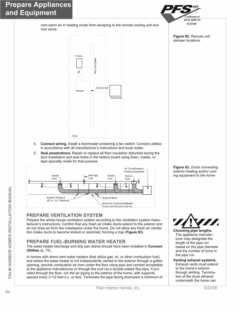
Prepare Appliances and Equipment
86Palm Harbor Homes, Inc. 9/22/08
vent warm air in heating mode from escaping to the remote cooling unit and vice versa.
PALM
HA
RB
OR
HO
MES
INST
ALL
ATI
ON
MA
NU
AL
DampersExter ior Duct
Remote Unit
F urnace
Mai
n Du
ct Sy
stem
Home
Figure 82. Remote unit damper locations
4. Connect wiring. Install a thermostat containing a fan switch. Connect utilities in accordance with all manufacturer’s instructions and local codes.
5. Seal penetrations. Repair or replace all floor insulation disturbed during the duct installation and seal holes in the bottom board using foam, mastic, or tape specially made for that purpose.
SupplyDuct
SupplyDuct
ReturnDuct
Air Conditioning orHeating Equipment
MarriageLine
Support Block
Minimum Clearance BetweenDucts and Ground to be 4 in.
Support Straps at48" in. O.C. Minimum
Figure 83. Ducts connecting exterior heating and/or cool-ing equipment to the home
PREPARE VENTILATION SYSTEM Prepare the whole-house ventilation system according to the ventilation system manu-facturer’s instructions. Confirm that any fresh air intake ducts extend to the exterior and do not draw air from the crawlspace under the home. Do not allow any fresh air ventila-tion intake ducts to become kinked or restricted, forming a trap (Figure 83). Choosing pipe lengths.
The appliance manufac-turer may designate the length of the pipe run based on the pipe diameter and the number of turns in the pipe run.
PREPARE FUEL-BURNING WATER HEATER The water heater discharge and drip pan drains should have been installed in Connect Utilities (p. 75).
In homes with direct-vent water heaters (that utilize gas, oil, or other combustion fuel), and where the water heater is not independently vented to the exterior through a grilled opening, provide combustion air from under the floor using pipe and cement acceptable to the appliance manufacturer or through the roof via a double-walled flue pipe. If pro-vided through the floor, run the air piping to the exterior of the home, with supports spaced every 3-1/2 feet o.c. or less. Terminate the pipe facing downward a minimum of
Venting exhaust systems.Exhaust vents must extend to the home’s exterior through skirting. Termina-tion of the dryer exhaust underneath the home can
#05
Conforms toHUD MHCSS
10/20/08
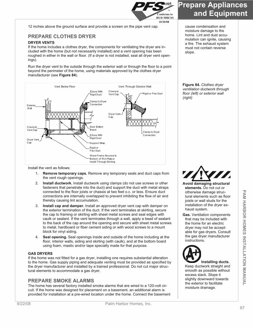
PAM
HA
RB
OR
HO
MES IN
STALLA
TION
MA
NU
AL
Prepare Appliances and Equipment
9/22/08 Palm Harbor Homes, Inc. 87
12 inches above the ground surface and provide a screen on the pipe vent cap. cause condensation and moisture damage to the home. Lint and dust accu-mulation can ignite, causing a fire. The exhaust system must not contain reverse slope.
PREPARE CLOTHES DRYER DRYER VENTS If the home includes a clothes dryer, the components for ventilating the dryer are in-cluded with the home (but not necessarily installed) and a vent opening has been roughed in either in the wall or floor. (If a dryer is not installed, seal all dryer vent open-ings).
Run the dryer vent to the outside through the exterior wall or through the floor to a point beyond the perimeter of the home, using materials approved by the clothes dryer manufacturer (see Figure 84).
Clamp toVent Cap Rigid or Flex Duct
Clamp to DryerConnection
Vent Through Exterior Wall
Elbow WithRigid Duct
Clamp to DryerConnectionExterior
Wall
Clamp toVent Cap
Vent Below Floor
Dryer VentCap
Wood Frame Secured toBottom of Rim Plate orInstall Through Skirting
Rigid orFlex Duct
Support Strap
Elbow WithRigid Duct
Seal BottomBoard
Dryer VentCap
Figure 84. Clothes dryer ventilation ductwork through floor (left) or exterior wall (right)
Install the vent as follows: 1. Remove temporary caps. Remove any temporary seals and duct caps from
the vent rough openings. 2. Install ductwork. Install ductwork using clamps (do not use screws or other
fasteners that penetrate into the duct) and support the duct with metal straps connected to the floor joists or chassis at two feet o.c. or less. Ensure duct connections are internally overlapped to prevent inhibiting the flow of air and thereby causing lint accumulation.
Avoid damaging structural elements. Do not cut or otherwise damage struc-tural elements such as floor joists or wall studs for the installation of the dryer ex-haust system.
3. Install cap and damper. Install an approved dryer vent cap with damper on the exterior termination of the duct. If the vent terminates at skirting, secure the cap to framing or skirting with sheet metal screws and seal edges with caulk or sealant. If the vent terminates through a wall, apply a bead of sealant to the back of the cap around the opening and secure with sheet metal screws to metal, hardboard or fiber cement siding or with wood screws to a mount block for vinyl siding.
Gas. Ventilation components that may be included with the home for an electric dryer may not be accept-able for gas dryers. Consult the gas dryer manufacturer instructions.
4. Seal opening. Seal openings inside and outside of the home including at the floor, interior walls, siding and skirting (with caulk), and at the bottom board using foam, mastic and/or tape specially made for that purpose.
GAS DRYERS If the home was not fitted for a gas dryer, installing one requires substantial alteration to the home. Gas supply piping and adequate venting must be provided as specified by the dryer manufacturer and installed by a trained professional. Do not cut major struc-tural elements to accommodate a gas dryer.
Installing ducts.Keep ductwork straight and smooth as possible without excess slack. Slope it slightly downward towards the exterior to facilitate moisture drainage.
PREPARE SMOKE ALARMS The home has several factory installed smoke alarms that are wired to a 120-volt cir-cuit. If the home was designed for placement on a basement, an additional alarm is provided for installation at a pre-wired location under the home. Connect the basement
#05
Conforms toHUD MHCSS
10/20/08
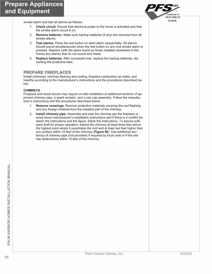
Prepare Appliances and Equipment
88Palm Harbor Homes, Inc. 9/22/08
PALM
HA
RB
OR
HO
MES
INST
ALL
ATI
ON
MA
NU
AL
smoke alarm and test all alarms as follows: 1. Check circuit. Ensure that electrical power to the home is activated and that
the smoke alarm circuit is on. 2. Remove batteries. Make sure backup batteries (if any) are removed from all
smoke alarms. 3. Test alarms. Press the test button on each alarm sequentially. All alarms
should sound simultaneously when the test button on any one smoke alarm is pressed. Replace (with the same brand as those installed elsewhere in the home) any alarms that do not sound and retest.
4. Replace batteries. After successful test, replace the backup batteries, dis-carding the protective tabs.
PREPARE FIREPLACES Install chimneys, chimney flashing and roofing, fireplace combustion air inlets, and hearths according to the manufacturer’s instructions and the procedures described be-low.
CHIMNEYSFireplace and wood stoves may require on-site installation of additional sections of ap-proved chimney pipe, a spark arrestor, and a rain cap assembly. Follow the manufac-turer’s instructions and the procedures described below:
1. Remove coverings. Remove protective materials covering the roof flashing and any foreign material from the installed part of the chimney.
2. Install chimney pipe. Assemble and seal the chimney per the fireplace or wood stove manufacturer’s installation instructions and if there is a conflict be-tween the instructions and the figure, follow the instructions. To assure suffi-cient draft for proper operation, extend the chimney at least three feet above the highest point where it penetrates the roof and at least two feet higher than any surface within 10 feet of the chimney (Figure 86). Use additional sec-tion(s) of chimney pipe (not provided) if required by local code or if the site has obstructions within 10 feet of the chimney.
#05
Conforms toHUD MHCSS
10/20/08
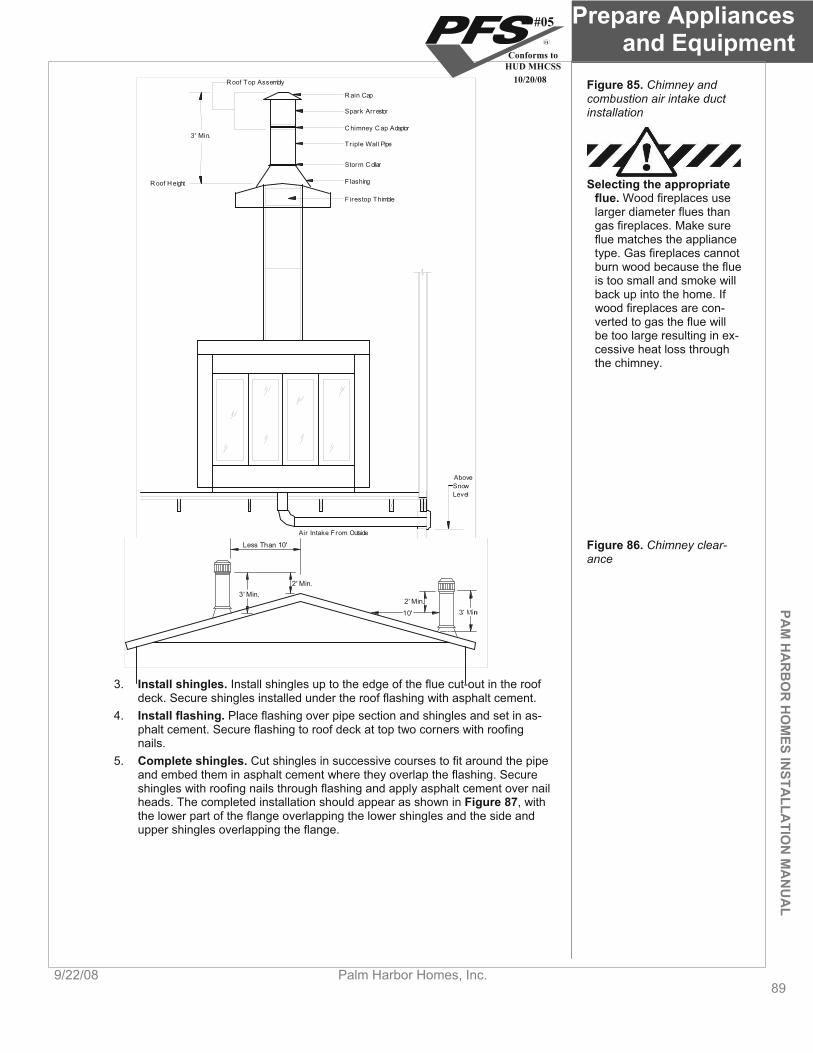
PAM
HA
RB
OR
HO
MES IN
STALLA
TION
MA
NU
AL
Prepare Appliances and Equipment
9/22/08 Palm Harbor Homes, Inc. 89
Air Intake From Outside
AboveSnowLevel
Rain Cap
Firestop Thimble
Flashing
Storm Collar
Tr iple Wall Pipe
Chimney Cap Adaptor
Spark Arrestor
Roof Height
Roof Top Assembly
3' Min.
Figure 85. Chimney and combustion air intake duct installation
Selecting the appropriate flue. Wood fireplaces use larger diameter flues than gas fireplaces. Make sure flue matches the appliance type. Gas fireplaces cannot burn wood because the flue is too small and smoke will back up into the home. If wood fireplaces are con-verted to gas the flue will be too large resulting in ex-cessive heat loss through the chimney.
Figure 86. Chimney clear-ance
2' Min.
10'
2' Min.3' Min.
Less Than 10'
3. Install shingles. Install shingles up to the edge of the flue cut-out in the roof deck. Secure shingles installed under the roof flashing with asphalt cement.
4. Install flashing. Place flashing over pipe section and shingles and set in as-phalt cement. Secure flashing to roof deck at top two corners with roofing nails.
5. Complete shingles. Cut shingles in successive courses to fit around the pipe and embed them in asphalt cement where they overlap the flashing. Secure shingles with roofing nails through flashing and apply asphalt cement over nail heads. The completed installation should appear as shown in Figure 87, with the lower part of the flange overlapping the lower shingles and the side and upper shingles overlapping the flange.
#05
Conforms toHUD MHCSS
10/20/08

Prepare Appliances and Equipment
90Palm Harbor Homes, Inc. 9/22/08
PALM
HA
RB
OR
HO
MES
INST
ALL
ATI
ON
MA
NU
AL
Push Down
Caulking
Flashing
12" Trim With Sheet MetalSheers If Difficult To MakeFlashing Lay Flat On Roof
Storm CollarFlange
Upper and SideShingles OverlapFlange and Are Set InAsphalt Cement
Lower Part of Flange
Flange
Flue Pipe
Roof Shingles
Figure 87. Roof flashing and shingle installation around chimney
COMBUSTION AIR INLETS Combustion air inlets provide combustion air through the floor or an exterior wall to a combustion appliance. If through an exterior wall, site installation is not required. If through the floor, extend the duct from its point just below the floor to the outside (addi-tional duct material required for this may or may not be provided with the home). Lo-cate the inlet damper above expected snow levels (contact the LAHJ for snow levels).
Installing combustion air inlets. Do not install the combustion air inlet such that material from the hearth can drop beneath the home.
Follow the fireplace manufacturer’s instructions (typically in the fireplace/stove or with the chimney parts).
HEARTHS If shipped loose, install the fireplace hearth according to the fireplace manufacturer’s instructions.
PREPARE KITCHEN AND BATH APPLIANCES / FIXTURES Install kitchen and bath appliances according to the manufacturer’s instructions and the procedures described for each appliance below.
Installing exhaust ducts.Route exhaust ducts so they do not terminate be-neath the home.
COOKING APPLIANCES If the home is provided with a range, cook top and/or grill containing its own exhaust system that penetrates the floor, complete the exhaust system as follows:
1. Remove covers. Remove the cover on the factory-installed exhaust pipe pro-truding from beneath the floor near the appliance.
2. Install termination fitting. Secure the provided termination fitting at the outside edge of the floor.
3. Install duct. Use the provided flexible metallic duct to connect the elbow pro-truding from the floor and the termination fitting. Refer to the manufacturer’s installation instructions for guidance on supporting the duct and making the connections.
SITE-INSTALLED GAS APPLIANCES Install only appliances with a Btu capacity equivalent to or less than the capacity of the factory-installed piping and at the location of a factory-installed gas riser.
REFRIGERATOR Prepare the refrigerator as follows:
Remove straps, blocks, or other securement devices used for shipping and patch any resulting marks on floors or walls.
If the refrigerator has an icemaker, check water lines for leaks upon installa-tion and a few days later to make sure no leaks have developed.
SITE-INSTALLED APPLIANCES AND FIXTURES If sinks, tubs, showers or other fixtures or appliances are to be site-installed, follow the manufacturer’s installation instructions. Use only products listed for use in manufac-tured homes and follow all applicable local codes.
#05
Conforms toHUD MHCSS
10/20/08
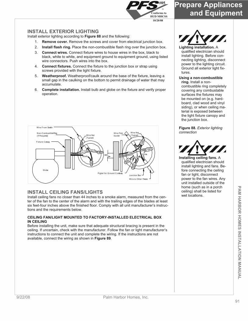
PAM
HA
RB
OR
HO
MES IN
STALLA
TION
MA
NU
AL
Prepare Appliances and Equipment
9/22/08 Palm Harbor Homes, Inc. 91
INSTALL EXTERIOR LIGHTING Install exterior lighting according to Figure 88 and the following:
1. Remove cover. Remove the screws and cover from electrical junction box. 2. Install flash ring. Place the non-combustible flash ring over the junction box. 3. Connect wires. Connect fixture wires to house wires in the box, black to
black, white to white, and equipment ground to equipment ground, using listed wire connectors. Push wires into the box.
4. Connect fixtures. Connect the fixture to the junction box or strap using screws provided with the light fixture.
5. Weatherproof. Weatherproof/caulk around the base of the fixture, leaving a small gap in the caulking on the bottom to permit drainage of water that may accumulate.
6. Complete installation. Install bulb and globe on the fixture and verify proper operation.
Lighting installation. A qualified electrician should install lighting. Before con-necting lighting, disconnect power to the lighting circuit. Ground all exterior light fix-tures.
Using a non-combustible ring. Install a non-combustible ring completely covering any combustable surfaces the fixtures may be mounted on (e.g. hard-board, clad wood and vinyl siding), or when ceiling ma-terial is exposed between the light fixture canopy and the junction box.
Figure 88. Exterior lighting connection
WhiteGround
Black
Black
GroundWhite
Pigtail for Ground Continuity
Wire to Other Fixture
Junction Box
Wire Nut(Typical)
Wire From Switch
Non-Combustible Ring(If R equired)
Fixture Canopy
Globe
Wire Nut(Typical)
Wire FromSwitch
Installing ceiling fans. A qualified electrician should install lighting and fans. Be-fore connecting the ceiling fan or light, disconnect power to the fan wires. Any unit installed outside of the home (such as in a porch ceiling) shall be listed for wet locations.
INSTALL CEILING FANS/LIGHTS Install ceiling fans no closer than 44 inches to a smoke alarm, measured from the cen-ter of the fan to the center of the alarm and with the trailing edges of the blades at least six feet-four inches above the finished floor. Comply with all unit manufacturer’s instruc-tions and the requirements below.
CEILING FAN/LIGHT MOUNTED TO FACTORY-INSTALLED ELECTRICAL BOX IN CEILING Before installing the unit, make sure that adequate structural bracing is present in the ceiling. If uncertain, check with the manufacturer. Follow the fan or light manufacturer’s instructions to connect the unit and complete the wiring. If the instructions are not available, connect the wiring as shown in Figure 89.
#05
Conforms toHUD MHCSS
10/20/08
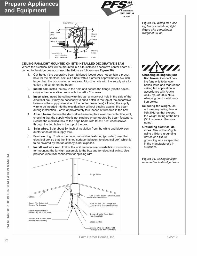
Prepare Appliances and Equipment
92Palm Harbor Homes, Inc. 9/22/08
PALM
HA
RB
OR
HO
MES
INST
ALL
ATI
ON
MA
NU
AL
Ground Wire
GroundStrap
Ceiling
Color CodedWires
Wire Nut
Ceiling Box
Limited orNoncombustibleRing (If Required) Chain
MountingScrew
Figure 89. Wiring for a ceil-ing fan or chain-hung light fixture with a maximum weight of 35 lbs
CEILING FAN/LIGHT MOUNTED ON SITE-INSTALLED DECORATIVE BEAM Where the electrical box will be mounted in a site-installed decorative center beam at-tached to the ridge beam, connect the fixture as follows (see Figure 90):
1. Cut hole. If the decorative beam (shipped loose) does not contain a precut hole for the electrical box, cut a hole with a diameter approximately 1/4 inch larger than the box’s using a hole saw. Align the hole with the supply wire lo-cation and center on the beam.
Choosing ceiling fan junc-tion boxes. Connect ceil-ing fans only to junction boxes listed and marked for ceiling fan application in accordance with Article 314.27(b) of 2005 NEC. Always ground metal junc-tion boxes.
2. Install box. Install the box in the hole and secure the flange (plastic boxes only) to the decorative beam with four #6 x 1” screws.
3. Insert wire. Insert the ceiling wire through a knock-out hole in the side of the electrical box. It may be necessary to cut a notch in the top of the decorative beam (on the supply wire side of the center beam hole) allowing the supply wire to be inserted into the electrical box without binding against the beam during installation. Leave approximately four inches of wire free in the box.
Selecting fan weight. Do not use any ceiling fans or light fixtures that exceed the weight rating of the box (35 lbs unless otherwise noted).
4. Attach beam. Secure the decorative beam in place over the center line joint, checking that the supply wire is not pinched or penetrated by beam fasteners. Secure the electrical box to the ridge beam with #8 x 2 1/2” wood screws through the two holes in the top of the box.
Grounding electrical de-vices. Ground fans/lights using a fixture-grounding device or a fixture-grounding wire as specified in the manufacturer’s in-structions.
5. Strip wires. Strip about 3/4 inch of insulation from the white and black con-ductor ends of the supply wire.
6. Position ring. Position the non-combustible flash ring (provided) over the electrical box so that the finished surface (adjacent to electrical box) which is to be covered by the fan canopy is not exposed.
7. Install and wire unit. Follow the unit manufacturer’s installation instructions for mounting the fan/light assembly to the box and for electrical wiring. Use provided electrical connectors for splicing wire.
Ceiling
Supply Wire Coiled AndSecured for Shipment
Notch Beam at Hole ifNecessary for Wire Chase
Secure Box to 2x6 CenterBeam (field-installed)
Secure Box to Ridge Beam(field installed)
Electrical Box
Hole for Box Cut Through 2x6(May Be Cut in Plant or in Field)
2x6 Center Beam - Shipped Loosefor Field Installation
Supply Wire Inserted in FieldThrough Side Knockout of Box
Ridge Beam
Figure 90. Ceiling fan/light mounted to flush ridge beam
#05
Conforms toHUD MHCSS
10/20/08

PAM
HA
RB
OR
HO
MES IN
STALLA
TION
MA
NU
AL
Prepare Appliances and Equipment
9/22/08 Palm Harbor Homes, Inc. 93
TEST ELECTRICAL SYSTEM After completion of all electrical wiring and connections, including crossovers, appli-ances, lights, and ceiling fans, inspect and test the electrical system as follows:
1. Fill water heater. Fill water heater before turning on power to the home or switching on the circuit breaker.
2. Test continuity. Before turning on the electrical power to the home, conduct an electrical continuity test to ensure that exposed metallic parts of the home and the chassis are effectively bonded.
3. Test operation. After turning on the electrical power to the home, conduct operational tests of all devices (except water heaters, electric ranges, electric furnaces, dishwashers, clothes washers/dryers, and portable appliances) to demonstrate that they are connected and in working order.
4. Test polarity. After turning on the electrical power to the home, conduct elec-trical polarity checks to determine that connections of electrical equipment in-stalled or completed during installation have been made properly. Visual veri-fication is an acceptable electrical polarity check.
go to Complete Exterior Work (p. 94).
#05
Conforms toHUD MHCSS
10/20/08

Complete Exterior Work
94Palm Harbor Homes, Inc. 9/22/08
Complete Exterior Work This chapter covers sealing the bottom board, installing the ground cover and skirting, preparing wind protection shutters, and completing site-built structures.
Follow the Steps below: STEP 1. REPAIR AND SEAL BOTTOM BOARD (p. 94)
STEP 2. INSTALL GROUND MOISTURE RETARDER (p. 94)
STEP 3 INSTALL SKIRTING (p. 95)
STEP 4 ASSEMBLE OPTIONAL WIND PROTECTION SHUTTERS (p. 95)
STEP 5. COMPLETE SITE-BUILT STRUCTURES (p. 95)
STEP 1. REPAIR AND SEAL BOTTOM BOARDTears and openings in the bottom board can result from transportation or installation activities. Inspect for holes and gaps the entire bottom board, especially areas around service penetrations, crossover connections, pipe and duct hangers, foundation ele-ments, and the perimeter of the floor. Using approved materials appropriate for the type of repair, repair the bottom board wherever torn or loosened as follows:
Sealing bottom boards. A continuous and sealed bot-tom board is critical for home performance, energy efficiency, protection against moisture problems, prevention of pipe freezing, and protection against in-sects and rodents.
1. Insulate. Replace any missing insulation prior to closure and repair of the bot-tom board, paying particular attention to insulation gaps that may have been created at P-traps.
2. Repair large openings. Repair large openings with a durable patch made of bottom board fabric or other compatible material and fastened with vinyl bot-tom board tape held in place by fasteners installed with a divergent stapler. Seal the edges around patches with foam or mastic. For large openings, in-stall a rigid backer board behind the bottom board to provide a fastening sub-strate for the patch.
Bottom board sealing methods. Tapes shall never be used alone to re-pair a bottom board. Diver-gent staples or mastic must be used in tandem with tape to prevent future tear off.
3. Repair small openings. Repair small gaps and tears with a combination of vinyl bottom board tape, patches, mastic, or foam sealant.
STEP 2. INSTALL GROUND MOISTURE RETARDER
PALM
HA
RB
OR
HO
MES
INST
ALL
ATI
ON
MA
NU
AL
If the space under the home is to be enclosed with skirting or other materials, a ground moisture retarder of a minimum six mil thick polyethylene sheeting or equivalent must be installed covering the ground under the home. Moisture retarders are not required in arid regions (less than 15 inches of rainfall annually) with dry soil conditions. If on-grade (surface) footings are used, install the ground moisture retarder prior to placing the footings, or install it around the footings after all other work under the home is com-plete.
Fastening vinyl siding. Do not install fasteners directly into vinyl siding. Allow for siding thermal expansion by pre-drilling minimum 1/2 inch diameter fastener holes or fastening skirting to a ledger under the home (see Best Practice tip).
Install the ground moisture retarder as follows:
1. Apply sheeting. Unroll the ground moisture overlapping joints in the sheeting a minimum of 12 inches and covering the entire area under the home except for areas under recessed entries, decks, and porches.
2. Seal joints. Seal joints in the retarder with mastic.
3. Weigh down. To keep the retarder in place, weigh it down with stones, concrete blocks, or other heavy, durable materials.
Avoiding radon.For enclosed perimeter wall crawlspace foundations in areas where radon is com-monly found in the soil, continue the moisture re-tarder up the perimeter wall
4. Repair tears. Repair any voids or tears in the retarder by patching with like ma-terial, maintaining a minimum 12-inch overlap and sealing joints with mastic.
#05
Conforms toHUD MHCSS
10/20/08
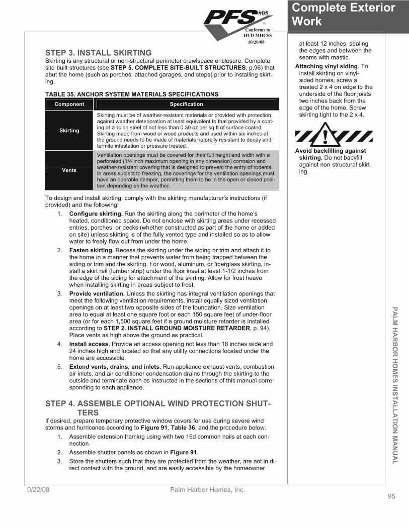
PALM
HA
RB
OR
HO
MES IN
STALLA
TION
MA
NU
AL
Complete Exterior Work
9/22/08 Palm Harbor Homes, Inc. 95
at least 12 inches, sealing the edges and between the seams with mastic. STEP 3. INSTALL SKIRTING
Skirting is any structural or non-structural perimeter crawlspace enclosure. Complete site-built structures (see STEP 5. COMPLETE SITE-BUILT STRUCTURES, p.96) that abut the home (such as porches, attached garages, and steps) prior to installing skirt-ing.
Attaching vinyl siding. To install skirting on vinyl-sided homes, screw a treated 2 x 4 on edge to the underside of the floor joists two inches back from the edge of the home. Screw skirting tight to the 2 x 4.
TABLE 35. ANCHOR SYSTEM MATERIALS SPECIFICATIONS Component Specification
Skirting must be of weather-resistant materials or provided with protection against weather deterioration at least equivalent to that provided by a coat-
Skirting ing of zinc on steel of not less than 0.30 oz per sq ft of surface coated. Skirting made from wood or wood products and used within six inches of the ground needs to be made of materials naturally resistant to decay and termite infestation or pressure treated.
Avoid backfilling against skirting. Do not backfill against non-structural skirt-ing.
Ventilation openings must be covered for their full height and width with a perforated (1/4 inch maximum opening in any dimension) corrosion and weather-resistant covering that is designed to prevent the entry of rodents. Vents In areas subject to freezing, the coverings for the ventilation openings must have an operable damper, permitting them to be in the open or closed posi-tion depending on the weather.
To design and install skirting, comply with the skirting manufacturer’s instructions (if provided) and the following:
1. Configure skirting. Run the skirting along the perimeter of the home’s heated, conditioned space. Do not enclose with skirting areas under recessed entries, porches, or decks (whether constructed as part of the home or added on site) unless skirting is of the fully vented type and installed so as to allow water to freely flow out from under the home.
2. Fasten skirting. Recess the skirting under the siding or trim and attach it to the home in a manner that prevents water from being trapped between the siding or trim and the skirting. For wood, aluminum, or fiberglass skirting, in-stall a skirt rail (lumber strip) under the floor inset at least 1-1/2 inches from the edge of the siding for attachment of the skirting. Allow for frost heave when installing skirting in areas subject to frost.
3. Provide ventilation. Unless the skirting has integral ventilation openings that meet the following ventilation requirements, install equally sized ventilation openings on at least two opposite sides of the foundation. Size ventilation area to equal at least one square foot or each 150 square feet of under-floor area (or for each 1,500 square feet if a ground moisture retarder is installed according to STEP 2. INSTALL GROUND MOISTURE RETARDER, p. 94).Place vents as high above the ground as practical.
4. Install access. Provide an access opening not less than 18 inches wide and 24 inches high and located so that any utility connections located under the home are accessible.
5. Extend vents, drains, and inlets. Run appliance exhaust vents, combustion air inlets, and air conditioner condensation drains through the skirting to the outside and terminate each as instructed in the sections of this manual corre-sponding to each appliance.
STEP 4. ASSEMBLE OPTIONAL WIND PROTECTION SHUT-TERS
If desired, prepare temporary protective window covers for use during severe wind storms and hurricanes according to Figure 91, Table 36, and the procedure below.
1. Assemble extension framing using with two 16d common nails at each con-nection.
2. Assemble shutter panels as shown in Figure 91.3. Store the shutters such that they are protected from the weather, are not in di-
rect contact with the ground, and are easily accessible by the homeowner.
#05
Conforms toHUD MHCSS
10/20/08

Complete Exterior Work
96Palm Harbor Homes, Inc. 9/22/08
To attach shutters to the home: 1. Fasten extension framing to wall framing materials with 16d double-headed
nails or #8 x 3” screws, toe nailed/screwed, per Table 36.2. Fasten assembled panel(s) to extension framing with 12d nails, per Table 36.
After use, remove shutters from the home, patch nail holes with caulk and store them as above.
PALM
HA
RB
OR
HO
MES
INST
ALL
ATI
ON
MA
NU
AL
Approx. 1"
Extension Framing #3or Stud Grade SPF2x3 or 2x4
Approx. 30Degrees
Cut If Desired
2x4 #2 SPFStudding, RequiredWhen Plywood orOSB Used Is 1
2" orLess In Thickness
Secure OSB orPlywood toStudding With 12dNails at 6" O.C.
Figure 91. Wind protection shutter construction
TABLE 36. SHUTTER CONSTRUCTION SPECIFICATIONS Wind Zones 2 & 3 Wind Zone 2 Wind Zone 3
Fastening to extension Fastening to wall framing Fastening to wall framing Panelthickness #8 x 3 #8 x 3 Window Extension
width framing (in) 12d nails 16d nails screws 16d nails screws 2 x 3* 7/16, 1/2 6 in. o.c. 8 in. o.c. 22 in. o.c. 6 in. o.c. 16 in. o.c.
Up to 48” 2 x 3 23/32, 3/4 6 in. o.c. 8 in. o.c. 22 in. o.c. 4-1/2 in. o.c. 12 in. o.c.
Up to 72” 2 x 3* 7/16, 1/2 4 in. o.c. 5 in. o.c. 14 in. o.c. 3 in. o.c. 8 in. o.c. * 2 x 3 perimeter extension with 2 x 4 studding at 16 inches o.c.
STEP 5. COMPLETE SITE-BUILT STRUCTURES Install site-built structures such as steps, landings, garages, awnings, carports, breezeways, porches, decks, railings, sheds, and utility rooms according to manufac-turer’s instructions (if any), in compliance with all local regulations including fire separa-tion and electrical requirements, and according to the following: Designing site-built struc-
tures. All site-built struc-tures must support their own dead, live, and wind loads and must not transmit any loads to the home’s structure. All car-ports should be freestand-ing.
Do not obstruct any of the two required exit doors from the home. Construct site-built structures to be structurally independent unless provided
for in the design of the home (instructions will be provided by the manufac-turer).
Do not damage the integrity of the home’s structural or weatherproofing sys-tem. Seal any weatherproofing connections between the site-built structure and the home and flash any roof connections.
Utilize only GFCI outlets for site-built structures. Install and test smoke alarms in any site-built structures according to local
code.
go to Prepare Home for Occupancy (p. 97).
#05
Conforms toHUD MHCSS
10/20/08
PALM
HA
RB
OR
HO
MES IN
STALLA
TION
MA
NU
AL
Prepare Home for Occupancy
9/22/08 Palm Harbor Homes, Inc. 97
Prepare Home for Occupancy Follow these steps for final inspection and completion of the home.
Follow the Steps below:
STEP 1.VERIFY ALTERNATIVE CONSTRUCTION (A/C) INSPECTION (p. 97)
STEP 2. COMPLETE INSPECTION CHECKLIST (p. 97)
STEP 3. COMPLETE ENERGY STAR CHECKLIST (p. 97)
STEP 4. CLEAN THE HOME (p. 97)
STEP 1. VERIFY ALTERNATIVE CONSTRUCTION (A/C) IN-SPECTION
This is normally the responsibility of the retailer and the manufacturer, however, the in-stallation is not complete until the alternative construction inspection has been passed and documented.
STEP 2. COMPLETE INSPECTION CHECKLIST After all previous steps have been accomplished, inspect the home to verify that it has been completely and properly installed using the checklist starting on p. 98.
Correct any deficiencies found, if possible, or if not possible, inform the retailer or manufacturer immediately.
STEP 3. COMPLETE ENERGY STAR CHECKLIST For ENERGY STAR qualified homes (check with the retailer or manufacturer), this step is to be completed by the manufacturer’s designated representative. Ask the retailer or the manufacturer who this is.
The manufacturer’s representative must complete the Energy Star Site Installation Checklist, obtain signatures on the ENERGY STAR label, and return the completed ENERGY STAR Site Installation Checklist to the manufacturing plant.
STEP 4. CLEAN THE HOME Remove and properly dispose of all installation-generated dust, debris, and packaging materials from the home and the surrounding property. Ensure that the home is in “move-in” condition.
Installation is Complete
#05
Conforms toHUD MHCSS
10/20/08

Complete Installation Checklist
98Palm Harbor Homes, Inc. 9/22/08
Complete Installation Checklist Use this checklist to confirm that the listed aspects of the installation are complete and correct.
FOUNDATION Footings properly sized and constructed for the soil conditions Pier spacing per data plate and applicable table and roof load zone
Limits of the checklist. This checklist is not all-inclusive. Some homes have impor-tant features not listed here. Completing this checklist does not guaran-tee that all installation re-quirements have been met.
Piers properly constructed and vertical Perimeter blocking installed (if required) Piers at each side of large sidewall openings Center line piers installed at columns Shims in place and tight
ANCHORS Approved anchors are used Anchors are installed at correct angles Anchor spacing and installation correct Longitudinal ties installed (if required) Anchor straps are tensioned
UNDER THE HOME Moisture retarder installed The ground is properly graded to prevent water accumulation HVAC ducts are supported off the ground and connected tightly to collars at all ends Fireplace combustion air intake free and unrestricted No holes or tears in bottom board Skirting has been installed per manufacturer’s instructions with proper vent-ing and provision for frost heave Dryer vent, range/cook top exhaust, water heater temperature and pressure overflow pipe and AC condensate drain installed to perimeter of crawl space
EXTERIORShingled roofs are free of visible damage and serious defects and there are no missing or loose shingles
PALM
HA
RB
OR
HO
MES
INST
ALL
ATI
ON
MA
NU
AL
Shingle close-up and ridge cap have been completed per applicable details All hold down straps on shingled roofs have been removed and staple holes have been properly sealed Penetrations at roof stacks, vents and chimneys have been properly sealed Siding and trim is free of gaps, voids, missing fasteners, damage, and seri-ous defects. All seams are sealed and hardboard edges are sealed Drip edge and fascia is properly installed and free of damage and serious de-fectsGutters and downspouts are installed properly such that water is diverted away from the home Trees and bushes have been trimmed to prevent brushing against the home in windy conditions or under snow loads The HUD label is exposed, intact and legible The exterior of the home and immediate surroundings is clean, clear of con-struction materials, dust, and debris
#05
Conforms toHUD MHCSS
10/20/08

PALM
HA
RB
OR
HO
MES IN
STALLA
TION
MA
NU
AL
Complete Installation Checklist
9/22/08 Palm Harbor Homes, Inc. 99
INTERIORCeilings, walls, and floor coverings are free from damage and serious defects Carpeting is properly stretched and seamed All trim and molding is installed properly and free of damage and defects All cabinets, countertops, plumbing fixtures, appliances, furnishings, and window coverings are free of damage or serious defects All cabinet doors and drawers work properly All interior and exterior doors and windows open, close, and latch properly One window in each bedroom meets emergency egress requirements, has operating instruction labels on it, and operates properly All temporary shipping hardware has been removed Floors are level The data plate is intact and legible Smoke alarms have been tested The interior of the home is clean, clear of materials, dust, and debris
WATER AND DRAIN SYSTEMS Crossover and service connection and splices have been properly made with correct materials Water and drain lines are insulated or otherwise protected from freezing Pipe supports are installed and properly spaced Proper slope has been maintained on all drain lines All necessary inspections and tests have been performed All sinks, basins, tubs, and toilets operate properly All hot and cold water lines are properly connected to fixtures, dispense wa-ter as labeled, and operate properly
ELECTRICAL SYSTEMS The panel amperage matches the connection to the home The home has been properly grounded The main power supply has been properly connected and tested by a li-censed electrician All electrical crossovers have been connected All receptacles, switches, and light fixtures operate properly Ground fault circuit interrupters operate properly All exterior lights have been properly installed
GAS/FUEL OIL SYSTEMS The gas system pressure test has been conducted Connections between units are properly made with access as required The main fuel line has been properly connected and tested by a qualified technician
APPLIANCE OPERATING AND VENTING All appliances are working properly Appliance venting is in accordance with the manufacturer’s instructions Fresh air intakes are properly installed Whole house, kitchen, and bath exhaust fan operation are correct Fireplace chimney stack extension and roof cap have been installed in ac-cordance with the manufacturer’s instructions
#05
Conforms toHUD MHCSS
10/20/08

Complete Installation Checklist
100Palm Harbor Homes, Inc. 9/22/08
PALM
HA
RB
OR
HO
MES
INST
ALL
ATI
ON
MA
NU
AL
Air conditioner/heat pump is sized properly
MISCELLANEOUS Installation/anchoring certificates or seals have been issued and installed (if required) Owner’s and operation manuals are available for all appliances This installation manual is left with home
#05
Conforms toHUD MHCSS
10/20/08

PALM
HA
RB
OR
HO
MES IN
STALLA
TION
MA
NU
AL
Index of Steps
9/22/08 Palm Harbor Homes, Inc. 101
Index of Steps INTRODUCTION .......................................................................................................2
IMPORTANT NOTICES............................................................................................................................. 2SAFETY ..................................................................................................................................................... 2RESOURCES ............................................................................................................................................ 2FEDERAL PREEMPTION.......................................................................................................................... 3DEFINITIONS ............................................................................................................................................ 3ENGINEER’S STAMP................................................................................................................................ 4SYMBOLS USED IN THE MANUAL ......................................................................................................... 5ABBREVIATIONS...................................................................................................................................... 5ALTERNATIVE FOUNDATION SYSTEMS ............................................................................................... 5DISPLAY AND STORAGE OF THE HOME .............................................................................................. 5
GETTING STARTED.................................................................................................7STEP 1. LOCATE THE DATA PLATE ...................................................................................................... 7STEP 2. CONFIRM WIND ZONE............................................................................................................... 7STEP 3. CONFIRM THERMAL ZONE....................................................................................................... 8STEP 4. CONFIRM ROOF-LOAD ZONE................................................................................................... 9STEP 5. CHECK LOCAL CODES AND SECURE PERMITS.................................................................... 10
PREPARE THE SITE ................................................................................................12STEP 1. PLAN SITE ACCESS .................................................................................................................. 12STEP 2. DETERMINE HOME LOCATION AND LAYOUT ........................................................................ 12STEP 3. CLEAR AND GRADE THE SITE................................................................................................. 13STEP 4. DETERMINE SOIL CONDITION ................................................................................................. 13STEP 5. DETERMINE SOIL-BEARING CAPACITY AND FROST LINE................................................... 14STEP 6. DETERMINE GROUND ANCHOR HOLDING CAPACITY.......................................................... 15
INSTALL FOOTINGS................................................................................................17STEP 1. DESIGN POINT LOAD SUPPORTS ........................................................................................... 17STEP 2. DESIGN FRAME SUPPORTS (Homes Without Perimeter Blocking)...................................... 20STEP 3. DESIGN FRAME AND PERIMETER SUPPORTS (Homes With Perimeter Blocking)............. 21STEP 4. SELECT FOOTING MATERIALS................................................................................................ 22STEP 5. SIZE FOOTINGS ......................................................................................................................... 22STEP 6. INSTALL FOOTINGS .................................................................................................................. 25
CONSTRUCT FOUNDATIONS.................................................................................27STEP 1. OBTAIN A FOUNDATION DESIGN ............................................................................................ 27STEP 2. EXCAVATE ................................................................................................................................. 27STEP 3. CONSTRUCT THE FOOTING OR SLAB.................................................................................... 27STEP 4. CONSTRUCT THE PERIMETER WALL ..................................................................................... 27STEP 5. INSTALL INTERIOR SUPPORTS ............................................................................................... 28STEP 6. WATERPROOF FOUNDATION WALL....................................................................................... 28STEP 7. BACKFILL AND GRADE ............................................................................................................ 28
SET THE HOME........................................................................................................29STEP 1. PREPARE FOR SET ................................................................................................................... 29STEP 2. POSITION HOME SECTION ....................................................................................................... 29STEP 3. LIFT HOME.................................................................................................................................. 29STEP 4. CONSTRUCT PIERS................................................................................................................... 31
COMPLETE MULTI-SECTION SET..........................................................................35STEP 1. INSTALL MARRIAGE LINE ANCHORS ..................................................................................... 35
#05
Conforms toHUD MHCSS
10/20/08

Index of Steps
102Palm Harbor Homes, Inc. 9/22/08
PALM
HA
RB
OR
HO
MES
INST
ALL
ATI
ON
MA
NU
AL
STEP 2. REMOVE PROTECTIVE SHIPPING MATERIALS...................................................................... 35STEP 3. COMPLETE HINGED ROOF....................................................................................................... 35STEP 4. REPAIR OR INSTALL MARRIAGE LINE GASKET ................................................................... 36STEP 5. POSITION ADDITIONAL HOME SECTIONS.............................................................................. 36STEP 6. CONNECT FLOORS ................................................................................................................... 37STEP 7. CONNECT ROOF........................................................................................................................ 38STEP 8. CONNECT WALLS ..................................................................................................................... 40STEP 9. ATTACH TAG UNITS.................................................................................................................. 41STEP 10. REMOVE TEMPORARY ITEMS................................................................................................ 42STEP 11. FASTEN HOME TO FOUNDATION .......................................................................................... 42STEP 12. BACKFILL AND GRADE .......................................................................................................... 42STEP 13. BUILD STAIRS.......................................................................................................................... 42
COMPLETE ROOF AND EXTERIOR WALLS..........................................................43STEP 1. COMPLETE ROOF...................................................................................................................... 43STEP 2. COMPLETE TAG UNIT ROOF.................................................................................................... 45STEP 3. COMPLETE SIDE WALLS.......................................................................................................... 47
CONNECT CROSSOVERS.......................................................................................48STEP 1. CONNECT DUCTS...................................................................................................................... 48STEP 2. CONNECT ELECTRICAL CROSSOVERS ................................................................................. 50STEP 3. INSTALL ELECTRICAL BONDING ............................................................................................ 53STEP 4. CONNECT WATER LINES.......................................................................................................... 53STEP 5. CONNECT DRAIN, WASTE, AND VENT LINES ........................................................................ 54STEP 6. CONNECT GAS LINES............................................................................................................... 56STEP 7. CONNECT TELEPHONE AND CABLE TV WIRING .................................................................. 57
COMPLETE THE INTERIOR ....................................................................................58STEP 1. ALIGN MARRIAGE WALLS........................................................................................................ 58STEP 2. FINISH GYPSUM BOARD........................................................................................................... 58STEP 3. COMPLETE WALL AND CEILING FINISHES............................................................................ 58STEP 4. COMPLETE CARPET ................................................................................................................. 59STEP 5. COMPLETE TRIM ....................................................................................................................... 59STEP 6. INSTALL SHIP LOOSE ITEMS................................................................................................... 59
INSTALL STABILIZING SYSTEM ............................................................................60STEP 1. DETERMINE ANCHOR LOCATIONS ......................................................................................... 60STEP 2. DETERMINE TIE-DOWN CONFIGURATION.............................................................................. 69STEP 3. SELECT ANCHORS.................................................................................................................... 69STEP 4. INSTALL ANCHORS................................................................................................................... 70STEP 5. INSTALL STRAPS ...................................................................................................................... 71STEP 6. TIGHTEN AND ADJUST STRAPS.............................................................................................. 74
CONNECT UTILITIES...............................................................................................75STEP 1. CONNECT ELECTRICAL SERVICE........................................................................................... 75STEP 2. CONNECT WATER SERVICE .................................................................................................... 78STEP 3. CONNECT GAS SERVICE.......................................................................................................... 81STEP 4. CONNECT OIL SERVICE............................................................................................................ 82
PREPARE APPLIANCES AND EQUIPMENT ..........................................................84INSTALL AIR CONDITIONER OR HEAT PUMP ...................................................................................... 84PREPARE HEATING SYSTEM ................................................................................................................. 85INSTALL REMOTE HEATING AND COOLING EQUIPMENT .................................................................. 85PREPARE VENTILATION SYSTEM ......................................................................................................... 86
#05
Conforms toHUD MHCSS
10/20/08
PALM
HA
RB
OR
HO
MES IN
STALLA
TION
MA
NU
AL
Index of Steps
9/22/08 Palm Harbor Homes, Inc. 103
PREPARE FUEL-BURNING WATER HEATER........................................................................................ 86PREPARE CLOTHES DRYER .................................................................................................................. 87PREPARE SMOKE ALARMS ................................................................................................................... 87PREPARE FIREPLACES .......................................................................................................................... 88PREPARE KITCHEN AND BATH APPLIANCES / FIXTURES................................................................. 90INSTALL EXTERIOR LIGHTING............................................................................................................... 91INSTALL CEILING FANS AND LIGHTING............................................................................................... 91TEST ELECTRICAL SYSTEM................................................................................................................... 93
COMPLETE EXTERIOR WORK ...............................................................................94STEP 1. REPAIR AND SEAL BOTTOM BOARD ..................................................................................... 94STEP 2. INSTALL GROUND MOISTURE RETARDER ............................................................................ 94STEP 3. INSTALL SKIRTING.................................................................................................................... 95STEP 4. ASSEMBLE OPTIONAL WIND PROTECTION SHUTTERS ...................................................... 95STEP 5. COMPLETE SITE-BUILT STRUCTURES................................................................................... 96
PREPARE HOME FOR OCCUPANCY.....................................................................97STEP 1. VERIFY ALTERNATIVE CONSTRUCTION (A/C) INSPECTION................................................ 97STEP 2. COMPLETE INSPECTION CHECKLIST..................................................................................... 97STEP 3. COMPLETE ENERGY STAR CHECKLIST................................................................................. 97STEP 4. CLEAN THE HOME..................................................................................................................... 97
COMPLETE INSTALLATION CHECKLIST ..............................................................98
#05
Conforms toHUD MHCSS
10/20/08

104
NOTES

Copyright © 2008 by Palm Harbor Homes, Inc.all Rights Reserved.More Home For Your Money!
15303 Dallas Parkway
Suite 800
Addison, TX 75001
Phone: (972) 991-2422
www.palmharbor.com
PalM HaRboR HoMesbuIldIng CenteR loCatIons
teMPe309 S. Perry Lane Tempe, AZ 85281 (800) 467-7877(480) 829-7091
austIn 830 Bastrop Hwy. Austin, TX 78741 (800) 880-7923(512) 385-2910
Plant CIty 605 S. Frontage Rd. Plant City, FL 33563-9934 (800) 729-4363(813) 752-7280
Ft. WoRtH Masterpiece Housing 6901 Bowman Roberts Rd. Ft. Worth, TX 76179(888) 424-6636(817) 238-8733
albeMaRle 2000 Sterling Drive Albemarle, NC 28001 (800) 677-3783 (704) 982-9838
MIlleRsbuRg 3737 Palm Harbor Drive Millersburg, OR 97321 (800) 928-2083(541) 926-4835
buda3700 Kyle Crossing Kyle, TX 78640 (800) 669-4484(512) 295-5166