on Integration of Unmanned Aerial Vehicles into Future … · Preliminary Study CARE INNOVATIVE...
153
Final Report CARE Innovative Action Preliminary Study on Integration of Unmanned Aerial Vehicles into Future Air Traffic Management Version 1.1 7 th December 2001 Industrieanlagen-Betriebsgesellschaft mbH Dept. Airborne Air Defence Einsteinstr. 20 D-85521 Ottobrunn
Transcript of on Integration of Unmanned Aerial Vehicles into Future … · Preliminary Study CARE INNOVATIVE...

Final Report
CARE Innovative Action
Preliminary Study
on
Integration of Unmanned Aerial
Vehicles into Future Air Traffic
Management
Version 1.1
7th December 2001
Industrieanlagen-Betriebsgesellschaft mbH
Dept. Airborne Air Defence
Einsteinstr. 20
D-85521 Ottobrunn

Preliminary Study CARE INNOVATIVE ACTION
Integration of Unmanned Aerial Vehicles into future Air Traffic Management
Date: 10.12.01Page 2
Executive Summary
Today Air Traffic Management (ATM) is closely related to safe and economic air
transportation. Looking at the huge number of daily conducted flights this implies a
tremendous task. The situation is expected to become more complicated in near future since
air traffic is increasing steadily and, despite the recent events, is expected to follow this trend
in the next decades. This demands enormous efforts to maintain safe and economic ATM
services within the available, limited airspace in recognition of all environmental constraints.
The situation is aggravated by various development programmes for Unmanned Aerial
Vehicles (UAV), which various operators will claim for integration into ATM rather soon.
Currently the military UAV market is growing with increasing pace. Recent UAV applications
in military conflict zones have numerously demonstrated that UAV technology meanwhile
have achieved a considerable level of production standard and reliability in many areas.
As such UAV key-technologies which are also applicable to civil UAVs are mainly available
or at least under development. These technologies offer a wide range of potential civil
applications like support of search and rescue activities, environmental surveillance, pollution
detection, weather monitoring, fire monitoring, mapping, coastal and border surveillance and
control, surveillance of infra-structural facilities (pipelines, airports, railways, roads,
waterways, etc.), airborne telecommunication relay-station and airborne crime
reconnaissance.
However, the civil UAV market has not yet started significantly. Main restraints for that can
be identified as follows:
• Certification Procedures and Regulations for civil UAVs are currently almost undefined.
• Air Traffic Management Regulations and Procedures for a commonly used airspace
environment which allows the operation of civil UAVs have not been developed.
These items lead to the innovative spirit of this study:
By investigation of the impact of UAV operations on Air Traffic Management (ATM), problem
and conflict areas between UAVs and other related traffic have to be identified in order to
develop adequate air traffic management procedures which will provide the initial
environment for the integration of such vehicles into ATM. As a further result of this approach
the corresponding design requirements for UAVs can be identified.
Consequently, this study helps to evolve the civil UAV market to start from the technology
spin-off out of current military development and technology.

Preliminary Study CARE INNOVATIVE ACTION
Integration of Unmanned Aerial Vehicles into future Air Traffic Management
Date: 10.12.01Page 3
Contents
1 Introduction........................................................................................................................ 12
2 Motivation and Innovation of the Study ............................................................................ 17
3 Current UAV-Systems and Programs – Status and Trends ............................................ 20
3.1 Overview of present UAV Programmes ....................................................................... 20
3.2 UAV Classification......................................................................................................... 21
3.3 Overview of Present UAV Systems and Programmes ................................................. 22
3.3.1 Illustration of the UAV Categorisation.................................................................... 24
3.4 Operation Control .......................................................................................................... 27
3.4.1 Air Traffic Control (ATC) ........................................................................................ 27
3.4.2 UAV Control Stations (UCS).................................................................................. 27
3.4.3 Data Link ................................................................................................................ 29
3.4.4 Navigation System................................................................................................. 33
3.4.5 Flight Management System................................................................................... 33
3.4.6 Other Relevant Equipment..................................................................................... 33
3.5 Consideration of Achievable Flight Path Accuracy ...................................................... 33
3.5.1 Preliminary Classification Scheme for Accuracy of Trajectory ............................. 33
3.6 Preliminary Assessment of Failure Modes ................................................................... 34
3.6.1 General Description of the Failure Mode Table..................................................... 34
3.6.2 Function Areas for Failure Mode Assessment ...................................................... 35
3.6.3 Phases of Flight ..................................................................................................... 36
3.6.4 Modes of Operation................................................................................................ 37
3.6.5 Severity Categorisation.......................................................................................... 38
4 Impact of UAV Operations on ATM.................................................................................. 40
4.1.1 UAV Flights within Controlled Airspace................................................................. 41
4.1.2 UAV Flights within Uncontrolled Airspace............................................................. 45
4.1.3 UAV Operations within Special Use Airspace....................................................... 46
4.2 Provision of Separation and Collision Avoidance......................................................... 46
Preliminary Study CARE INNOVATIVE ACTION
Integration of Unmanned Aerial Vehicles into future Air Traffic Management
Date: 10.12.01Page 4
4.2.1 Basic Regulations for Separation and Collision Avoidance.................................. 46
4.2.2 Separation Safety................................................................................................... 47
4.3 Procedures for UAV Hand-Over and Border Crossing................................................. 49
4.4 Ground Operations........................................................................................................ 50
4.4.1 Guidance and control by the UCS......................................................................... 51
4.4.2 Independent surveillance function, performed by ATC (Ground control) ............. 51
4.5 Military Operations ........................................................................................................ 52
4.6 Flight Termination System (FTS).................................................................................. 52
5 Proposed ATM Requirements .......................................................................................... 53
5.1 ATM Requirements ....................................................................................................... 53
5.1.1 UAV operations in existing air route scheme (IFR)............................................... 53
5.1.2 UAV operations outside existing air route scheme (off airways). ......................... 54
5.1.3 UAV operations in uncontrolled air space. ............................................................ 54
5.2 Procedures .................................................................................................................... 55
Impact of UAV Ops on ATM.............................................................................................. 56
ATM Requirement / Procedure ......................................................................................... 56
5.3 Integration of UAV into different Airspace Categories.................................................. 59
5.3.1 Definition of Decisive Features and UAV Integration Effort .................................. 59
5.3.2 UAV Integration into Present Airspace Classes.................................................... 61
5.3.3 UAV Integration into Future Airspace Categories ................................................. 63
6 Follow-up Study Proposal ................................................................................................. 65
6.1 Contents and Objectives ............................................................................................... 65
6.2 Simulation Tools ............................................................................................................ 66
6.2.1 MILSIM Simulation Environment ........................................................................... 66
6.2.2 Extended Air Defence Testbed.............................................................................. 68
7 References........................................................................................................................ 69
8 Appendix A – Tables of UAV............................................................................................ 71
8.1 Explanation of data fields and used abbreviations ....................................................... 71

Preliminary Study CARE INNOVATIVE ACTION
Integration of Unmanned Aerial Vehicles into future Air Traffic Management
Date: 10.12.01Page 5
8.1.1 Illustration of the UAV Categorisation.................................................................... 83
9 Appendix B – Representative Examples for UAV............................................................ 85
9.1 Class 0 - SCOUT 2000 ................................................................................................. 85
9.2 Class 1 - KZO (Brevel).................................................................................................. 87
9.3 Class 1 - OUTRIDER.................................................................................................... 89
9.4 Class 2 - PREDATOR................................................................................................... 91
9.5 Class 3 - Global Hawk................................................................................................... 93
10 Appendix C - Examples of Datalinks ................................................................................ 95
10.1 UAV “Mücke” ............................................................................................................. 95
10.2 UAV KZO / BREVEL................................................................................................ 96
10.3 UAV PIONEER.......................................................................................................... 97
10.4 UAV CL 289.............................................................................................................. 98
10.5 UAV Global Hawk...................................................................................................... 99
10.6 UAV Predator.......................................................................................................... 100
11 Appendix D – Airspace Categorisation........................................................................... 101
11.1 Air Traffic in European Airspace ............................................................................. 101
11.1.1 Basic Terms ..................................................................................................... 101
11.1.2 Airspace Classification..................................................................................... 102
11.2 Utilisation of European Airspace............................................................................. 103
11.2.1 Controlled Airspace.......................................................................................... 103
11.2.2 Uncontrolled Airspace...................................................................................... 105
11.2.3 Special Use Airspace....................................................................................... 105
12 Appendix E - Collision Avoidance................................................................................... 107
12.1 ACAS / TCAS / ETCAS ........................................................................................... 107
12.2 ADS-B...................................................................................................................... 108
12.3 Avoidance of Collision with Terrain ......................................................................... 108
13 Appendix F - Separation Safety...................................................................................... 109
Categorisation of manned Aircraft according to their Approach speeds (ICAO)........... 130

Preliminary Study CARE INNOVATIVE ACTION
Integration of Unmanned Aerial Vehicles into future Air Traffic Management
Date: 10.12.01Page 6
14 Appendix G - Detailed Description of Data Link ............................................................. 132
14.1 Description of Data Link .......................................................................................... 132
14.1.1 Function of Data Links: .................................................................................... 132
14.1.2 Characteristics of Data Links ........................................................................... 136
15 Appendix H - Preliminary Table of Failure Modes.......................................................... 141
16 Appendix I - Hand-Over and Border Crossing ............................................................... 144
17 Appendix J - Autonomous Flight..................................................................................... 146
17.1 Drones ..................................................................................................................... 148
17.2 Autonomy State 1, - No autonomy.......................................................................... 149
17.3 Autonomy State 2 – Autonomous manoeuvring, collision avoidance .................... 150
17.4 Autonomy State 3 – Autonomous, limited AI pilot available ................................... 151
17.5 Autonomy State 4 – Fully autonomous with sophisticated AI-Pilot available......... 153

Preliminary Study CARE INNOVATIVE ACTION
Integration of Unmanned Aerial Vehicles into future Air Traffic Management
Date: 10.12.01Page 7
List of Abbreviations
A/C Aircraft
ACARS Airborne Communications Addressing and Reporting System
ACAS Airborne Collision Avoidance System
ADC Air Data Computer
ADF Automatic Direction Finding
ADS-B Automatic Dependent Surveillance Broadcast
AGL Above Ground Level
AIC Aeronautical Information Circular
AIP Aeronautical Information Publication
AIS Aeronautical Information Services
AMSL Above Mean Sea Level
ASDE Airport Surface Detection Equipment
ATC Air Traffic Control
ATM Air Traffic Management
ATS Air Traffic Service
BLOS Beyond Line of Sight
CARE Co-operative Actions of R&D in EUROCONTROL
CDTI Cockpit Display of Traffic Information
CFIT Controlled Flight Into Terrain
COM Communication
CPA Closest Point of Approach
CPDLC Controller Pilot Data Link communication
CRC Cyclic Redundancy Check
CTR Control Zone
CVFR Controlled VFR
DGPS Differential GPS
DME Distance Measuring Equipment

Preliminary Study CARE INNOVATIVE ACTION
Integration of Unmanned Aerial Vehicles into future Air Traffic Management
Date: 10.12.01Page 8
DoD Department of Defence
DSSS Direct Sequence Spread Spectrum
EAD European AIS Database
ECAC European Civil Aviation Conference
EFIS Electronic Flight Information System
EGPWS Enhanced Ground Proximity Warning System
EO / IR Electro Optical / Infra Red
ESARR Eurocontrol Safety Regulations Requirements
ETCAS Enhanced TCAS
FAA Federal Aviation Authority
FHSS Frequency Hopping
FIS Flight information Service
FL Flight Level
FMS Flight Management System
FTS Flight Termination System
GCS Ground control Station
GNSS Global Navigation Satellite System
GPS Global Positioning System
HALE High Altitude Long Endurance
HF High Frequency
HMI Human Machine Interface
IAF Initial Approach Fix
IAS Indicated Air Speed
ICAO International Civil Aviation Organisation
IFF Identification Friend Foe
IFR Instrument Flight Rules
IFR Instrumental Flight Rules
IMC Instrumental Meteorological Conditions

Preliminary Study CARE INNOVATIVE ACTION
Integration of Unmanned Aerial Vehicles into future Air Traffic Management
Date: 10.12.01Page 9
INS Inertial Navigation System
Kbps Kilo bit per second
KIAS Knots Indicated Airspeed
LOS Line of Sight
LRE Launch And Recovery Element
MALE Medium Altitude Long endurance
MASPS Minimum Aviation Systems Performance Standard
Mbps Mega bit per second
MCE Mission Control Element
MMI Man Machine Interface
MMI Man Machine Interface
MOA Military Operation Area
MOPS Minimum Operational Performance Standards
MSL Medium Sea Level
MTOW Aircraft Maximum Take-Off Weight
NAVAID Navigational Aid
NAVAID Navigational Aids
NLOS Non Line of Sight
NOTAM Notice To Airmen
PIREP Pilot Report
PPR Prior Permission Required
P-RNAV Precision – Area Navigation
RA Resolution Advisory
RA Radio Altimeter or Resolution Advisory
RAIM Receiver Autonomous Integrity Monitoring
RNAV Area Navigation
RNP Required Navigation Performance
RTCA Radio Technical Commission for Aeronautics

Preliminary Study CARE INNOVATIVE ACTION
Integration of Unmanned Aerial Vehicles into future Air Traffic Management
Date: 10.12.01Page 10
RVSM Reduced Vertical Separation Minima
SAR Search and Rescue / Synthetic Aperture Radar
SATCOM Satellite Communication
SID Standard Instrument Departure
SIGINT Signal Intelligence
SSR Secondary Surveillance Radar
SST Super Sonic Transport
STAR Standard Arrival Route
STCA Short Term Conflict Alert
STOL Short Take Off and Landing
SUA Special Use Airspace
T/O Take Off
TA Traffic Advisory
TAWS Terrain Awareness and Warning System
TCAS Traffic Collision Avoidance Systems
TDMA Time Division Multiplex Access
TMA Terminal Control Area
TOW Take Off Weight
TRA Temporary Reserved Airspace
TUAV Tactical UAV
UAV Unmanned Air Vehicle
UCAV Unmanned Combat Air Vehicle
UCS UAV Control Station
VFR Visual Flight Rules
VHF Very High Frequency
VMC Visual Meteorological Conditions
VMC Visual Meteorological Conditions
VOR VHF Omni-directional Radio Range
Preliminary Study CARE INNOVATIVE ACTION
Integration of Unmanned Aerial Vehicles into future Air Traffic Management
Date: 10.12.01Page 11
VOR/DME Very High Frequency Omnidirectional Radio Range / Distance Measuring
Equipment
VTOL Vertical Take Off and Landing
Preliminary Study CARE INNOVATIVE ACTION
Integration of Unmanned Aerial Vehicles into future Air Traffic Management
Date: 10.12.01Page 12
1 Introduction
Today the idea of Air Traffic Management (ATM) is closely related to safe and economic air
transportation. Looking at the huge number of daily conducted flights this implies a
tremendous task. The situation is expected to become more complicated in near future since
air traffic is increasing steadily and, despite the recent events, is expected to follow this trend
in the next decades. This demands enormous efforts to maintain safe and economic ATM
services within the available airspace.
This touches another contradicting factor to higher airspace utilisation - the limitation of
resources. The airspace, frequencies for communication and data link are physically limited.
Another limiting factor is given by environmental constraints. Such constraints may result
from adverse weather conditions and even regulations and procedures of the ATM itself
imply limitations to the utilisation of airspace. An example for this is the fixed system of air
traffic routes and special procedures for noise reduction which are required in order to
minimise the impact of air traffic on the environment.
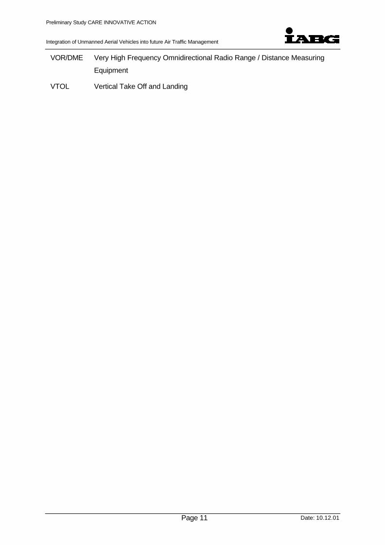
A new challenge which is already in progress will deteriorate this situation in the near future
and will introduce new aspects and dependencies to the current situation – Unmanned Aerial
Vehicles (UAV)1. Figure 1-1 provides an overview of the current situation:
Figure 1-1 - Factors influencing the Integration of UAVs into future ATM.
1 UAV is an abbreviation for “Unmanned Aerial Vehicle”. Some literature understand UAV as “Uninhabited Aerial
Vehicle” which refers to a technical equivalent meaning.
Unmanned Aerial VehiclesGrowing Number, Limited Reliability / Redundancy, Needs for ATM, etc.
Provision of High Quality ATM to Ensure Safe andEconomic Conduction of Air Transport
IncreasingDensity
ofAir Traffic
LimitedResources
Airspace,Data Link,
Frequencies,etc
Environ-mental
Constraints

Preliminary Study CARE INNOVATIVE ACTION
Integration of Unmanned Aerial Vehicles into future Air Traffic Management
Date: 10.12.01Page 13
Today a considerable number of development programmes for unmanned aerial vehicles are
rapidly progressing towards operational application. These programmes meet a large variety
of different applications, civil and military. In some areas even new operational aspects
(tasks) can be identified for future UAV applications which never have been dedicated to
manned flight. These areas are mainly derived from the UAV-typical abilities:
• to stay airborne for a couple of days in high altitudes,
• to be able for operations with high risk for damage or loss of aircraft withoutendangering the operation crews life,
• to perform flights with lightweight vehicles with much less costs than required for a fullpiloted aircraft.
These features allow many new beneficial UAV-applications, some of which are not even
thought about and need still adequate time for development. This trend is strongly supported
by technical improvements especially miniaturisation and improvements of technical
reliability. As such the market for UAV, both civil and military, is expected to see a very
strong increase.
As a spin-off from development for military applications the civil UAV market will envisage a
wide field for future UAV applications, e. g.:
• Support of Search and Rescue Activities,
• Environmental Surveillance / Pollution Detection / Weather Monitoring
• Fire Monitoring / Fire Fighting,
• Mapping,
• Coastal- / Border-Surveillance and Control,
• Surveillance of Infra-Structural Facilities (Pipelines, Airports, Railways, Roads,Waterways, Channels, High Tension Cables, etc.),
• Airborne Telecommunication Relay-Station,
• Airborne Crime Reconnaissance.
Since the technology required for such operations has been already prepared in most cases
for current military applications, the introduction of these UAV operations does not depend on
unavailable technology still to be developed. Instead these UAV applications mainly were
delayed by current shortfalls in certification requirements and missing procedural concepts
for the integration of UAVs into a commonly used airspace.
In summary these UAV development programmes will end up in an increasing demand for
airspace utilisation very soon, which need immediate measures to be taken in order to
support this request with adequate guidelines for the development and equipment of UAV.
The general aim of this effort is to enable the ATM system to guarantee the safe and orderly
flow of total air traffic (conventional air traffic and UAV traffic) under the new circumstances.

Preliminary Study CARE INNOVATIVE ACTION
Integration of Unmanned Aerial Vehicles into future Air Traffic Management
Date: 10.12.01Page 14
Actually there are two major areas identified which require more investigation to enable the
ATM system to be adequately prepared for this task:
• Establishment of common airworthiness requirements and according regulations forUAV,
• Establishment of common air traffic regulations and standardisation and derivedprocedures for adequate integration of UAV into Air Traffic Management Systems.
The first point involves national and international airworthiness authorities which should be
well aware that future airworthiness standards for UAV need to cover a wide range of
different applications – from the remotely controlled helicopter to large high altitude UAV,
autonomously cruising with sub-sonic speed with endurance of several days.
The second point addresses also the major focus of this study. It is important to note that
there are many cross-links between airworthiness and equipment requirements and the
corresponding air traffic procedures which could be utilised for an UAV. An example is
accuracy and reliability of the altitude information provided for the flight control system. Even
the cruise flight of a pre-programmed UAV requires accurate keeping of a given flight level. If
no other separation criteria to other related traffic are introduced, the equipment of the UAV
has to meet the requirements necessary in order to maintain the separation criteria for flight
safety reasons. Autonomous flight (Appendix J) includes also reactive measures,
autonomous and / or remote, of the UAV taken in order to avoid collisions with other related
traffic.
As such the effort spent for the integration of UAV into future air traffic management systems
is twofold: airworthiness requirements for the UAV and its equipment can directly be derived
if the ATM procedures, regulations and requirements are identified which the vehicle has to
comply with.
This reflects to the key idea of this preliminary study: The integration of UAV into future ATM
shall comply as best as possible with current standards and regulations. The overall aim of
the integration of UAV into future ATM should be to minimise the impact on other air traffic
regulations.
Initial start point of the study is an analysis and classification of current UAV systems and
future trends in order to identify main applications and related flight performance parameter
as mass, airspeed, endurance, altitude, manoeuvrability and flight task specific items. Very
important is the accuracy achievable in order to maintain a given flight path and the
corresponding reliability. This analysis shall also take into account the situation for possible
system failures and failure-identification. The failures for typical UAV of the identified classes
under consideration shall be analysed and categorised depending on their possible impact
on accuracy of maintaining an intended flight path.

Preliminary Study CARE INNOVATIVE ACTION
Integration of Unmanned Aerial Vehicles into future Air Traffic Management
Date: 10.12.01Page 15
Figure 1-2 shows a possible future integration of UAV in an ATM environment. Very
important for integration into air traffic management is the technical reliability and redundancy
of the navigation and flight control systems and of the data link to the UAV control station and
especially to the ATC organisations. For UAVs a new and very important aspect has to be
taken into account which is the communication or data link between ATC and the UAV
control authorities. This control station may be ground based or even airborne as well. As
such a wide variety of different conceptual approaches for the data link between ATC and
control station is possible. The air traffic control authority (ATC) and the UAV Control Station
(UCS), which performs the remote control of the UAV, form the initial network which enables
basic functionality for controlled flight of an UAV in a controlled airspace. The UAV itself may
be also active part of an data exchange network among other air traffic participants via TCAS
or ADS-B, for example. For safety reasons a back-up data-link between UAV Control station
and ATC is foreseen.
Air TrafficControl (ATC)UAV Control Station (UCS)
Ground COM
ADS B / TCAS ...
Figure 1-2 - Integration of UAV in an ATM environment
This first step into the investigation of this study will provide the following information:
• Range and variation between different UAV parameters with respect to their ability forintegration into ATM,
• Impact of system failures on flight path accuracy,
• Categorisation by means of flight task / mission applications.

Preliminary Study CARE INNOVATIVE ACTION
Integration of Unmanned Aerial Vehicles into future Air Traffic Management
Date: 10.12.01Page 16
This information provides supporting evidence for the second step of the study: an analysis
which impact of UAVs with various technical features could be expected on ATM. In addition
to analysis of UAV operations under normal (non-failure) conditions this investigation also will
be based on the failure assumptions for UAVs. The aim of this work is to briefly identify areas
of possible conflicts with other related traffic and as such to highlight resulting environmental
constraints for other related traffic. Such areas need further investigation and adequate
procedures for de-conflicting to be developed. In addition adequate level of information for
identification for ATM purposes is to be determined by these results.
This reflects the aim of the third step of this study, which mainly is focussed on work out of
ATM requirements and according procedures which enable UAVs for the integration into
ATM. These procedures should include all sections of a flight beginning with ground control,
taxi, take-off, climb, cruise, special task related issues for UAVs, descent, approach and
landing. For each section procedures for normal operation and for operation under failure
cases which may have impact on ATM-relevant parameter are to be taken into account.
According to the definition of UAV-procedures, the associated technical design-requirements
which UAVs have to meet become evident in order to achieve an adequate level of safety
and reliability for the UAV-integration into ATM. The workout of these ATM-related
requirements for UAVs requires a detailed coupling to recent airworthiness standards
respectively proposals for standards and as such is foreseen to be performed in the main
study due to time and funding constraints for the preliminary study.
This report is structured according to the step-wise approach described above. Following a
short description of the motivation and idea for this study in the next chapter, chapter 3 is
dedicated to the technical features of current UAVs and UAV development programmes with
special focus to ATM-relevant parameter like mass, airspeed, max. altitude, climb rate,
endurance, max. mission radius and data link (communications as addressed in Figure 1-2).
Chapter 4 of this study addresses possible conflict areas between UAVs and other related
traffic and subsequent impacts of hypothetical UAV-operations on ATM. These conflicts may
either be the result of different technical performance parameters between e. g. airliners and
UAVs or it could also be induced by special operations or manoeuvres required for the UAV
operation task (e. g. air launch from another carrier aircraft).
Chapter 5 of this study identifies possible air traffic procedures and requirements applicable
to the ATM-integration of UAVs with various technical features.
Chapter 6 presents the expected results of a proposed follow-on study based on the results
of this preliminary study and the funding. In order to estimate possible risks of this follow-on
study the feasibility will be analysed and stated.
Preliminary Study CARE INNOVATIVE ACTION
Integration of Unmanned Aerial Vehicles into future Air Traffic Management
Date: 10.12.01Page 17
2 Motivation and Innovation of the Study
Currently the military UAV market is growing with increasing pace. Most dominant
applications for military UAVs are reconnaissance and surveillance trials which often imply
long duration of flight in combination with high altitudes. The absence of on-board pilots in
these environmental conditions allows the UAV-design to be more stringent to that purpose.
Featuring a higher level of autonomy the UAV reduces the requirements to the pilot skills of
the UAV operator.
A very sound argument for military UAV is that pilots do not have to risk their lives especially
in the so called „high risk“-missions.
Besides that, the application of smaller UAVs may also reduce the costs per mission.
An outlook for the military UAV market confirms the enormous growth potential:
• Chairman of US Senate Armed Services Committee proposed in 2000 that a third of
deep-strike aircraft should be unmanned by 2010 [ 7].
• The world market for UAVs will experience growth throughout the forecast period 1998 to
2008. Revenues for the total market in 1998 reached approximately $2.1 billion [ 8].
• Americas military spends $1.2 billion a year on UAV research [ 7].
• US Air Force representative John Warden expects that 90 % of combat aircraft will be
unmanned by 2025 [ 7].
These figures clearly indicate that UAV development activities are in progress in a wide
range or even have been performed already. Recent UAV applications in military conflict
zones have numerously demonstrated that UAV technologies meanwhile have achieved a
considerable level of production standard in many areas.
As such UAV key-technologies which are also applicable to civil UAVs are mainly available
or at least under development. However, the civil UAV market has not been started
significantly.
This is also cormfirmed by a current UAV market analysis, see also ref.[ 8]:
“While the military market segment will continue to support substantial revenue growth for the
UAV industry, the greatest challenge facing civil market growth remains with the difficulty in
establishing, co-ordinating and implementing airspace regulation that applies to all UAV
varieties. This is the greatest restraint of world-wide market growth, as case by case local

Preliminary Study CARE INNOVATIVE ACTION
Integration of Unmanned Aerial Vehicles into future Air Traffic Management
Date: 10.12.01Page 18
flight clearance and hard-to-obtain liability coverage restrict the ability of manufacturers to
demonstrate system capabilities.”
In summary the main restraints for that process are:
• Certification Procedures and Regulations for civil UAVs are currently almost undefined.
• Air Traffic Management Regulations and Procedures for an commonly used airspace
environment which allows the operation of civil UAVs have not been developed.
This addresses to the innovative spirit of this study:
By investigation of the impact of UAV operations on Air Traffic Management (ATM), problem
and conflict areas between UAVs and other related traffic have to be identified in order to
develop adequate air traffic management procedures which will provide the initial
environment for the integration of such vehicles into ATM. As a further result of this approach
the corresponding design requirements for UAVs can be identified.
Consequently, this study helps to evolve the civil UAV market to start from the technology
spin-off out of current military development and technology.
An interesting side aspect of this study results out of the analysis of data link protection,
integrity and security technologies for the UAV link to the control station (UCS). More than
any other manned aircraft UAVs have to rely on the data link to the UCS for reasons of safe
operation in the commonly used airspace. An analysis of the applicability of these features
for civil air traffic is of general value for the overall safety and robustness of ATM systems in
the light of increasing security needs due to terrorism threat.
Due to the large variety of possible civil UAV applications, as outlined in the introduction of
this report, the need for provision of an adequate air traffic control environment for UAVs will
materialise very soon.
An early indication for that may be the current planning of several research and development
programmes which intentionally will cover some of these aspects. A good example of such
activities is the EU-funded study “USICO” which will be started by April 2002. This approach
features a collaborative research investigation on the integration of a representative UAV
type into ATM. As such this study will intentionally support to improve the understanding how
to operate and certify such type of UAV in order to meet the requirements to be fit for flying in
a commonly used airspace.
Complementary to that USICO-approach this study initially starts from the assumption that
future civil UAVs may fulfil quite different tasks. For that reason the level of treatment and
care provided from ATC authorities has to be analysed and subsequently adopted and

Preliminary Study CARE INNOVATIVE ACTION
Integration of Unmanned Aerial Vehicles into future Air Traffic Management
Date: 10.12.01Page 19
balanced with the special kind of operation. This study will provide an overview of possible
near future UAV applications and an assessment of proposed corresponding ATM-
procedures, the USICO-study will provide a perspective of work to be performed in order to
achieve ATM integration at hand of a selected type of UAV.
Due to this complementary character the USICO-study will be supported by the results of this
preliminary study in agreement with Eurocontrol.
In the following, some initial examples indicate a taste of the variety of future civil UAV
applications :
• In the ARM (Atmospheric Radiation Measurement) programme by US Department of
Defence and the US Department of Energy, UAVs were used together with manned
aircraft
• NASA has proposed to use UAV to aid Hawaiian coffee growers and to research how
lightning forms and dissipates during thunderstorms
• A Sidney based team has proposed an interactive entertainment concept, where
customers pay to virtually fly using a combination of UAV, the internet and simulation
technologies
• At the university of Stuttgart (Germany) advanced concepts exist to use stratospheric
airships UAVs as relay stations for the new UMTS communication network. Thus the
need for a huge number of additional ground based transmitter/receiver stations can be
reduced considerably. The all electric airships will be powered by a mutual dependent
combination of solar generation and fuel cell. The technique works at least at laboratory
level.

Preliminary Study CARE INNOVATIVE ACTION
Integration of Unmanned Aerial Vehicles into future Air Traffic Management
Date: 10.12.01Page 20
3 Current UAV-Systems and Programs – Status and Trends
A precondition for an adequate integration of UAVs into an ATM-environment is knowledge
about the variety and dominance of such UAV-parameters which determine the ability for the
integration into the commonly used airspace. These parameters are:
• UAV design parameters (mass, speed range, climb and descent rate,manoeuverability, endurance),
• equipment of the UAV (avionics / sensors, on-board flight control system, control datalink),
• reliability and robustness of the overall design (failure tolerant design, redundancy,graceful degradation),
• operational environment of the UAV (UAV-control station, data link to UAV and ATC).
Among these factors UAVs feature a very important topic with regard to ATC, which is the
non-availability of an on-board pilot. This requires high reliability of the data link to the UAV,
and in case of loss of data link, a sufficient level of autonomy of the UAV.
Following the intention of this study this chapter intentionally introduces such technical
aspects of current and near future UAVs, their corresponding control station environment and
a brief overview of their possible failures on system level with regard to such failures which
may induce an impact on ATM.
3.1 Overview of present UAV Programmes
In order to be integrated into ATM systems UAVs will have to conform to ATM-regulations
and procedures especially to comply with safety requirements. For that purpose a technical
overview of UAV and current UAV programmes has to focus on such technical features
which may influence the level of accuracy of keeping an intended flight path. These areas
are:
• the redundancy and reliability of equipment (flight control system, navigation system,communication/data links, propulsion system),
• flight mechanic performance parameter (max. altitude, airspeed, climb rate, range,endurance, manoeuverability),
• the method and quality of guidance (remotely piloted, remotely guided),
• the communication/data link triangle between ATM, vehicle control station and vehicleincluding devices for the data exchange,

Preliminary Study CARE INNOVATIVE ACTION
Integration of Unmanned Aerial Vehicles into future Air Traffic Management
Date: 10.12.01Page 21
• impact of system failures on operational aspects and system reaction.
At the first glance the large variety of different UAVs prevents a clear identification of the way
forward towards integration of UAV into air traffic management. For that purpose adequate
criteria for classification of UAV into groups or classes are required which basically could be
used to establish conformance to current ATM-procedures and requirements.
A very basic but important key feature is the method applied for the steering and controlling
of the vehicle. Actually there is a twofold development:
• Remotely controlled / piloted UAV:Such systems are basically steered by an active operator from a ground or air basedcontrol station. These systems induce normally a reasonable high workload to theoperator and require all ATC-related data exchange (incl. communication) with thatremote-controlling operator. Currently there is only a small number of such vehicles(e.g. PREDATOR-System incl. operator control and steering box ).
• Remotely guided UAV:Such systems have a high level of integrity and normally apply automatic flight controlalgorithms for the steering and controlling of the vehicle. On-board flight managementsystems allow the systems to operate autonomous for standardised / pre-setapplications. Within that environment the remote operator acts mainly as a systemmonitor and guides the vehicle via flight-task and way-point setting operations. TheATC-related data exchange will be performed partly by the on-board system itself (e.g.position, flight intention) and partly by the remote operator who will act mainly forclearance acceptance and to solve problems or unexpected events.
A more detailed separation of the different levels of autonomy is introduced in the Appendix J
- Autonomous Flight. Currently, the mainstream of UAV development adhere to the remotely
guided UAV principles. In the near future the trend to higher autonomy of the vehicle will
maintain and as such the remotely controlled / piloted UAV will decrease. This aspect
indicates that the method of control may not be an adequate scheme for a classification of
UAV.
From that viewpoint a classification is introduced using of flight mechanic basic parameters
and performance parameters. In the following a classification scheme is introduced based on
the maximum take-off weight and an additional categorisation based on the propulsion
system.
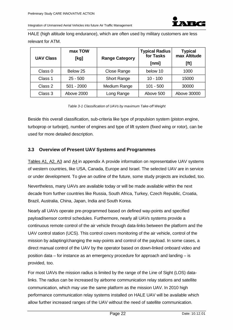
3.2 UAV Classification
The classification proposed below is based on the maximum take-off weight (max. TOW) of
the air vehicle, similar to manned aircraft. These weight categories correlate very well with
other classifications criteria like range, mission radius and maximum flight altitude.
Classifications based on the type of mission, like tactical UAV (TUAV), combat UAV (UCAV)
etc., or based on altitude and endurance, like MALE (medium altitude long endurance) or
Preliminary Study CARE INNOVATIVE ACTION
Integration of Unmanned Aerial Vehicles into future Air Traffic Management
Date: 10.12.01Page 22
HALE (high altitude long endurance), which are often used by military customers are less
relevant for ATM.
UAV Class
max TOW
[kg] Range Category
Typical Radiusfor Tasks
[nmi]
Typicalmax Altitude
[ft]
Class 0 Below 25 Close Range below 10 1000
Class 1 25 - 500 Short Range 10 - 100 15000
Class 2 501 - 2000 Medium Range 101 - 500 30000
Class 3 Above 2000 Long Range Above 500 Above 30000
Table 3-1 Classification of UAVs by maximum Take-off Weight
Beside this overall classification, sub-criteria like type of propulsion system (piston engine,
turboprop or turbojet), number of engines and type of lift system (fixed wing or rotor), can be
used for more detailed description.
3.3 Overview of Present UAV Systems and Programmes
Tables A1, A2, A3 and A4 in appendix A provide information on representative UAV systems
of western countries, like USA, Canada, Europe and Israel. The selected UAV are in service
or under development. To give an outline of the future, some study projects are included, too.
Nevertheless, many UAVs are available today or will be made available within the next
decade from further countries like Russia, South Africa, Turkey, Czech Republic, Croatia,
Brazil, Australia, China, Japan, India and South Korea.
Nearly all UAVs operate pre-programmed based on defined way-points and specified
payload/sensor control schedules. Furthermore, nearly all UAVs systems provide a
continuous remote control of the air vehicle through data-links between the platform and the
UAV control station (UCS). This control covers monitoring of the air vehicle, control of the
mission by adapting/changing the way-points and control of the payload. In some cases, a
direct manual control of the UAV by the operator based on down-linked onboard video and
position data – for instance as an emergency procedure for approach and landing – is
provided, too.
For most UAVs the mission radius is limited by the range of the Line of Sight (LOS) data-
links. The radius can be increased by airborne communication relay stations and satellite
communication, which may use the same platform as the mission UAV. In 2010 high
performance communication relay systems installed on HALE UAV will be available which
allow further increased ranges of the UAV without the need of satellite communication.

Preliminary Study CARE INNOVATIVE ACTION
Integration of Unmanned Aerial Vehicles into future Air Traffic Management
Date: 10.12.01Page 23
Representative UAV of Class 0 (below 25 kg)
This class covers very small, close range UAV which are summarised in Table A1 for
information only, as this type of UAV is not relevant for ATM.
Representative UAV of Class 1 (25 to 500 kg)
In this class many UAVs are available (Table A2). Most of these are military UAVs which are
used for reconnaissance, surveillance and target acquisition / designation. These UAVs are
primarily driven by internal combustion engines (piston or rotary) with pusher or tractor
propeller. With this type of propulsion the flight velocity is limited to 150 – 200 kts. For higher
speeds, small turbojets are used, resulting in much lower endurance.
Due to antenna size, weight and cost the UAVs of this class are not equipped with satellite
communication systems. Hence, the mission radius is normally limited to the data-link LOS
range (e.g. 100 nmi). Navigation is primarily based on GPS or DGPS. In some cases inertial
navigation systems (INS) with GPS update are installed.
Representative UAV of Class 2 (501 to 2000 kg)
In this class we will find most of the medium range, medium altitude endurance UAVs (Table
A3). A mission radius of up to 500 nmi is provided if communication relays or satellite data-
links are used. Most UAVs feature hybrid navigation systems (INS + GPS) and wheeled
takeoff and landing. Beside fixed wing vehicles UAVs with vertical takeoff and landing
capability (VTOL) are also available. The endurance and range of these UAVs are much
lower.
Representative UAV of Class 3 (above 2000 kg)
This class covers the high altitude long endurance (HALE) and combat UAV which require
higher payload capacities (Table A4). The satellite communication systems allow ranges of
greater 500 nmi. The UAV are typically driven by turboprop or turbofan engines.
The first military combat UAV (UCAV) are in the demonstrator phase, today. These are the
Boeing X-45 and the Northrop Grumman X-47 (Pegasus) which will be ship based. The
UCAV are the only UAV that carry explosive weapons.

Preliminary Study CARE INNOVATIVE ACTION
Integration of Unmanned Aerial Vehicles into future Air Traffic Management
Date: 10.12.01Page 24
3.3.1 Illustration of the UAV Categorisation
Appendix A provides a visualisation of the spread of main design parameters (e.g. mass,
airspeed, etc.) versus the maximum Take-Off Weight for different UAVs. Figure A1 to Figure
A4 provide a visualisation of such data which were selected from Table A1 to A4.
In Figure 3-1 the selected UAV are shown in an altitude versus takeoff mass diagram. It is
demonstrated that at higher altitudes the UAV are bigger and heavier. This is because the
payload size and weight increases with altitude due to the necessary longer range of the
payload, e.g. sensors and effectors. Furthermore, the UAV range and endurance increase,
too.
The scientific UAVs “Altus” and “Perseus B” are smaller although operating at high altitudes
as they are equipped with much smaller/lighter payloads.
In Figure 3-2 the UAV classes are correlated with altitude and flight velocity. It can be seen
that the speed is primarily a function of the type of propulsion system. With piston engines
driving a propeller (pusher or tractor) the preferred speed range is 150 kts. The turboprop
engines providing higher power than piston engines allow flight velocities up to 300 kts.
Above 300 kts turbofan engines are required. In this speed range (300 to 400 kts) counter-
rotating turboprops or prop-fans would further increase the endurance or allow smaller
platforms, but these engines are not off-the-shelf available, today.
The UCAV are carrying higher payload (weapons) than the reconnaissance and mission
support UAV and operating at higher speeds to increase the survivability.

Preliminary Study CARE INNOVATIVE ACTION
Integration of Unmanned Aerial Vehicles into future Air Traffic Management
Date: 10.12.01page 25
Figure 3-1 - UAV classes shown in an altitude versus takeoff mass diagram
Altitude versus max Takeoff Weight (Fixed Wing)
0
10000
20000
30000
40000
50000
60000
70000
1 10 100 1000 10000 100000
Takeoff Mass [kg]
Alti
tude
[ft
]
Class 1 (25 - 500 kg)
Class 2 (501 - 2000 kg)
Class 3 (above 2000 kg)
Class 0 (below 25 kg)
UAV for scientific
missions with small payload
Class 0 Class 1
Class 2
Class 3

Preliminary Study CARE INNOVATIVE ACTION
Integration of Unmanned Aerial Vehicles into future Air Traffic Management
Date: 10.12.01page 26
Altitude Versus max Speed (Fixed Wing)
0
10000
20000
30000
40000
50000
60000
70000
0 100 200 300 400 500 600 700
Max. Flight Velocity [kts]
Alt
itu
de
[ft]
Class 1 (25 - 500 kg)
Class 2 (501 - 2000 kg)
Class 3 (above 2000 kg)
Class 0 (below 25 kg)
Class 3Turboprop
Class 3Turbofan
Class 1+2piston/rotary eng.without turbocharger
Class 2piston/rotary eng.with turbocharger
Class 0piston eng.or electric
Primarily mil UAV(Class 2+3)Turbofan
HALE
LO HALE
MALE
UAV for scientific missions with small payload
Figure 3-2 - Correlation of the UAV classes with altitude and flight velocity

Preliminary Study CARE INNOVATIVE ACTION
Integration of Unmanned Aerial Vehicles into future Air Traffic Management
Date: 10.12.01page 27
3.4 Operation Control
A precondition for the safe integration of an UAV into air traffic management is the reliable
and secure operation control. This includes all technical devices which enable a bi-directional
data exchange between the UAV and corresponding operation control authorities. The data
exchange normally is separated in data which addresses operation related data and data
which describes ATC-related information. Normally, for integrity reasons, different technical
devices are used for the transmission of these two different data. For most applications this
twofold-approach for the data/communication link to a UAV offers a possibility for higher
redundancy in case of technical failures or damage of the ATC-related data-exchange
devices.
3.4.1 Air Traffic Control (ATC)
To maintain a safe, orderly and smooth air traffic, which also takes care of economic
aspects, each European state has established an air traffic provider.
The functions of these Air Traffic Service (ATS) providers include above all Air Traffic Control
(ATC) as well as acceptance, processing and forwarding of flight plans. Furthermore the
providers are responsible for planning, installation and maintenance of all technical systems,
required to fulfil these functions and of the navigation facilities for the airspace users.
Air Traffic Control comprises all phases of flight including ground operations in almost all
parts of airspace.
Flying in the civil managed airspace requires in the most cases the establishment of a
continuous two way communication via radio and/or data link (in the future), to perform all
interactive tasks between ATC and the responsible UAV operator, as between ATC and the
crew of manned aircraft.
These tasks comprise requesting and delivery of clearances, the advises necessary to
maintain the separation and especially the handling of emergencies.
3.4.2 UAV Control Stations (UCS)
The UAV control stations have to cover the following tasks:
• Mission planning
• Vehicle control during taxi, takeoff, approach and landing
• Vehicle control and guidance during flight
• Sensor control and payload/sensor data processing, display and exploitation

Preliminary Study CARE INNOVATIVE ACTION
Integration of Unmanned Aerial Vehicles into future Air Traffic Management
Date: 10.12.01page 28
• Image distribution to users
• Communication with operators and Air Traffic Control (ATC)
The number of tasks and levels of interaction depend on the type of UAV and the missions to
be performed. They can be categorised as follows:
Figure 3-3 - UAV Control Station Levels of Interaction
For long range systems, the UAV might be controlled by two or more UCS , e.g. one for
launch and recovery at the home-airport and another one, which may be far away from the
home-airport and the area where the UAV is accomplishing his task.
Beside ground based UCS, the UCS can be sea or air based, depending on the operational
requirements.
Air Vehicle / Sensor
No link tothe UAV
Only DataReceipt
DataReceipt
PayloadControl
DataReceipt
PayloadControl
FlightControl
DataReceipt
PayloadControl
FlightControl
Launch &Recovery
Level I Level II Level III Level IV Level V
UCS Levels of Interaction

Preliminary Study CARE INNOVATIVE ACTION
Integration of Unmanned Aerial Vehicles into future Air Traffic Management
Date: 10.12.01page 29
Figure 3-4 - Beyond line-of-sight operation with a HALE UAV using a remote airport (operating base)
Figure 3-5 - UAV Control Station (typical)
3.4.3 Data Link
The types of UAV data links and their requirements highly depend on the objectives of the
intended operation. The main characteristics are the operational range and the flight/mission
control capabilities as well as high availability and robustness of the data link.

Preliminary Study CARE INNOVATIVE ACTION
Integration of Unmanned Aerial Vehicles into future Air Traffic Management
Date: 10.12.01page 30
Currently the UAV use three types of data-link established between the UAV and the UAV
control station:
• flight and task control data-link
• system monitoring data-link
• task data-link
as shown in the following Figure 3-6:
Figure 3-6 - Data Links between UAV and UCS (scheme)
For flights of UAV in a commonly used airspace data links between UAV and ATC have to be
established. For airborne conflict detection and solution between UAV and other air traffic,
either manned or unmanned, a data link has to be established, for example ADS-B which is
planned to be established within the next years. The possible scenario is shown in the
following figure including the stated links:
• Data link between UAV and UAV Control Station (UCS). This link is mainly used fortask related data and direct UAV control.
• Data link between UAV and Air Traffic Control (ATC). This link is mainly used for AirTraffic Control, which means for example provision of separation including clearancesand spacing manoeuvres.
DATA LINKOperational Range (Distance)
Performance and QualityProtection of Link and Data
FLIGHT ANDTASK
CONTROLDATA
SYSTEMMONITORING
DATA
TASK DATA
UAV UCS

Preliminary Study CARE INNOVATIVE ACTION
Integration of Unmanned Aerial Vehicles into future Air Traffic Management
Date: 10.12.01page 31
• Data link between airborne vehicles. This link, possible ADS-B, could be establishedprimarily between all “mobile” participants in air traffic to provide data exchangeneeded for conflict detection and collision avoidance.
• Additionally a data link between entities like ATC and UCS could be established. Thislinks could provide direct access to the UAV-operator and serve as a backup forenhanced safety.
Air TrafficControl
Ground COM
Satellite
UAV
LowAltitude
UAV
UAV ControlStation (UCS)
Remote UCS
ADS-B
MannedAircraft
GroundCOM
Figure 3-7 - Data-and communication links (schematic overview)
Safety requirements for data links
The criticality of airborne vehicle operation requires a sufficient level of safety. This is
especially true for operation of UAVs which are controlled and accessed by data link.
Therefore the data link has to be designed to the following qualities:
• Safety
• Security and integrity (data protection)
• Availability and robustness (link protection)
Investigation into these subjects is of general benefit for civil air traffic and especially in times
of increased security needs due to terrorism threat.

Preliminary Study CARE INNOVATIVE ACTION
Integration of Unmanned Aerial Vehicles into future Air Traffic Management
Date: 10.12.01page 32
In the following Table 3-2 an overview on data links of selected UAV is presented. For details
on data links and data links of UAV, already implemented or planned, see Appendix C.
Name Manufacturer Nation Data Link UAV-Class
Mücke EADS Germany HF 1
KZO(Brevel)
STN ATLAS(Eurodrone)
Germany(FR/GE)
LOS (Ku)(C2 & video)
1
Phoenix GEC-MarconiAvionics
UK LOS (J)(C2 & video)
1
Pioneer Pioneer UAV(AAI/IAI)
USA LOS (C+UHF)(C2 & video)
1
Ranger Orlikon-Contraves
Switzer-land
LOS (UHF+MW)(C2 & video)
1
CL 289 EADS DornierCanadairSAT
GermanyCanadaFrance
only video (IR) down-link(LOS)
1
Mirach 150 Meteor CAE Italy LOS(C2 & video)
1
SperwerHV(high velocity)
SAGEM France LOS (Ku)(C2 & video)
1
Eagle-Eye Bell Helicopter USA LOS (C+UHF) dual up (C2) &single down
2
Seamos EADS Dornier Germany LOS (C2 & video)Ku 1-10 Mbps, UHF 10 Kbps),BLOS (C2) HF 1Kbps
2
GlobalHawk(Tier II plus)
NorthropGrumman(Teledyne RyanAeronautical)
USA LOS (X-band + UHF)SATCOM (Ku+UHF)(all C2 & video)
3
Predator B GeneralAtmoics
USA LOS (C-band,)SATCOM (Ku+UHF)(C2 & video)
3
GE UCAV EADS Germany LOS (X-/Ku-band, UHF),SATCOM (Ku+UHF), HF(BLOS)
3
Table 3-2 - UAV Selected for Analysis of Data Link (Overview)

Preliminary Study CARE INNOVATIVE ACTION
Integration of Unmanned Aerial Vehicles into future Air Traffic Management
Date: 10.12.01page 33
3.4.4 Navigation System
There is different navigation equipment aboard the UAV. The commonly used source for
position finding is Global Positioning System (GPS). Details of navigation systems of specific
UAVs are described in the according tables.
3.4.5 Flight Management System
The Flight Management System (FMS) used in manned aircraft contains databases for all
way-points and navigation aids in the respective area. The planned route of a particular flight
is entered before commencement of the flight, updates are possible at any time. Further the
FMS keeps track of all relevant data concerning a particular flight, for example fuel data. For
autonomously operating UAV a similar system has to be realised and accessible for the UAV
controller.
Having access to the flight management system has to be part of requirements for UAV; this
should be discussed in more detail in the follow-up study.
3.4.6 Other Relevant Equipment
Integration of UAVs into ATM could lead to a requirement for carrying TCAS, Collision
Warning System or Transponder. For details on collision warning equipment refer to
Appendix E – Collision Avoidance.
3.5 Consideration of Achievable Flight Path Accuracy
Considerations of achievable flight path accuracy are beyond the scope of the preliminary
study. This should be accomplished, on the basis of the UAV data available, in the follow-up
study.
However, to give already some guidance for the follow-up study in the following chapter a
preliminary classification scheme is provided.
3.5.1 Preliminary Classification Scheme for Accuracy of Trajectory
For a better handling the achievable flight path accuracy should be categorised and put into
an appropriate classification scheme. A possible and preliminary scheme could contain
• Accuracy categoryThis is the category identifying the achievable accuracy.
• Grade of deviation from planned / required flight pathThis row contains the description of the grade of deviation from flight path. Deviation inthis context means lateral and/or vertical deviation with respect to time.

Preliminary Study CARE INNOVATIVE ACTION
Integration of Unmanned Aerial Vehicles into future Air Traffic Management
Date: 10.12.01page 34
• Explanation / DefinitionThe grade of horizontal deviation in feet or lateral deviation in nautical miles and thetime margin for recovery. If either term is exceeded the deviation will be transferred intothe next category.
A preliminary classification scheme is shown below, it should be stressed, that it should be
refined or even adapted during the follow-up study if necessary.
AccuracyCategory
Grade of Deviation fromPlanned / Required Flight Path
Explanation / Definition
I No Deviations -
II Minor Deviations Deviations in altitude of not morethan 100 feet. Lateral deviations of
not more than a nautical mile.
UAV is able to correct deviationwithin 10 seconds.
III Remarkable / ConsiderableDeviations
Deviations in altitude of not morethan 500 feet. Lateral deviations ofnot more than one nautical miles.
UAV is able to correct deviationwithin 30 seconds.
IV Extreme Deviations Deviations in altitude of more than500 feet. Lateral deviations ofmore than one nautical miles.
UAV is not able to correctdeviation within 30 seconds.
Table 3-3 - Preliminary Classification Scheme for Flight Path Deviation
3.6 Preliminary Assessment of Failure Modes
3.6.1 General Description of the Failure Mode Table
In this chapter the general approach for the assessment of the failure modes is presented. A
detailed assessment will be part of the follow-up study; however, some failure modes were
already described preliminary and entered in the table for failure modes. The exemplary table
is attached to this report in Appendix H.
The table for the failure modes includes the following items, for details see Figure 3-8:
• FunctionThe area of functionality, the description of the areas is given below.

Preliminary Study CARE INNOVATIVE ACTION
Integration of Unmanned Aerial Vehicles into future Air Traffic Management
Date: 10.12.01page 35
• Failure modeThe failure mode to be regarded.
• Flight phaseThe phase of flight for the occurrence of the failure; the description of the phases isgiven below.
• Operational consequencesThe operational consequences of the respective failure mode is described.
• Hazard descriptionThe hazard resulting, or possibly resulting from the respective failure mode isdescribed. Emphasis is given to ATM related hazards.
• Severity categoryThe severity of the hazard resulting from a failure mode, if there is more than onehazard, the most severe hazard will be given. The description of the severitycategorisation is given below.
For the completion of the Failure Mode Table, workshops with experts from all relevant
sectors and experiences, for example Air Traffic controllers, UAV operators and system
engineers should be used. The structure of the table is shown in the following Figure, the
table with exemplary failure modes inserted preliminary is attached in Appendix H.
Figure 3-8 - Structure of Failure Mode Table
3.6.2 Function Areas for Failure Mode Assessment
Presently there are six basic function areas identified which are listed below:
• Engine powerThis area covers all engine problems, i.e. total loss of engine power and partial loss ofengine power in different phases of flight.
• ATC data linkThis area covers the data link between ATC and the UAV including possibly existing
FUNCTION FLIGHTPHASE
FAILUREMODE
OPERATIONALCONSEQUENCES
HAZARD DESCRIPTION(ATM-VIEW)
SEVERITYCATEGORY

Preliminary Study CARE INNOVATIVE ACTION
Integration of Unmanned Aerial Vehicles into future Air Traffic Management
Date: 10.12.01page 36
voice communications between ATC and the UAV controller. All ATM related data areexchanged via the ATC data link.
• UAV control data linkThis area covers the data link which is established between the UAV and the UAVcontrol station. It is used for all control purposes and control-related data.
• ControllabilityThis area covers all airborne UAV control functions, either mechanically orelectronically. For example all control surfaces, possibly existing hydraulic systems,flight control system including computers and further more.
• Navigation / AvionicsThis area covers all devices used for navigation purposes as well as all devices usedfor maintenance of either 4-dimensional trajectory or separation purposes. Thisincludes for example Air Data Computers (ADC), Radar Altimeter (RA) and especiallyall sense and avoid devices.
• MiscellaneousThis area covers all functions which are not covered by the areas mentioned above.This could include items as for example payload or mission related equipment as wellas fuel status, onboard self testing and failure identification etc.
3.6.3 Phases of Flight
For the further proceeding the following phases of flight are foreseen to be regarded for the
identified failure modes:
• Flight PlanningThis phase includes all activities for the flight preparation, for example the routeplanning, fuel calculation or filing of flight plans.
• Ground movementThis phase includes the movements between the gate, or a comparable position, andthe runway (taxi).
• Take offThis phase starts with commencement of take off roll and ends at 1500 feet aboveground. For UAV there are several take off modes identified:
- Normal Take-Off
- Vertical Take-Off
- Rocket-boosted Take-Off
- Air-Drop from Carrier-A/C
• Departure and climbThis phase starts at 1500 feet above ground and ends when the UAV reaches itscruising altitude. The departure may be flown using omni-directional departure orStandard Departure Routes (SID).
• CruiseThis phase starts when the UAV is reaching cruising altitude and ends with thecommencement of descent for approach and landing. This phase especially includesthe portion of the flight, of any duration, which could be called the “core intention” (inmilitary terms the mission), and is the purpose of the flight.

Preliminary Study CARE INNOVATIVE ACTION
Integration of Unmanned Aerial Vehicles into future Air Traffic Management
Date: 10.12.01page 37
• Special Operation / mil. Missions incl. leaving & re-entering the Air-Route Systemand/or the civil managed AirspaceThis phase may be either applicable to some military UAV missions which normallyhave to leave/re-enter the civil managed airspace if the area of military operation isreached/left; even more this special operation phase is dedicated to such UAV whichhave to leave/re-enter the air-route system (but not the civil managed airspace) if theflight task (e. g. surveillance, mapping, airborne Telecommunication relay-station, etc.)requires a departure from other ATM regulations (e.g. air-route System).
• Descent and arrivalThis phase starts with commencement of descent at the end of the flight and ends atthe Initial Approach Fix (IAF), or an appropriate point. This might include radar vectors,transition routes or Standard Arrival Routes (STAR).
• Approach and landingThis phase starts at the IAF and ends with the vacation of the runway. For UAV thereare several landing modes identified:
- Normal Landing
- Vertical Landing
- Parachute Landing
- Docking at airborne Host A/C
3.6.4 Modes of Operation
Basically this document divides the operations of UAV in three modes of operation, which
are:
• Normal operations; they include
- Ground operations,
- In-flight operations with all systems working normal,
- Communication operations.
• Abnormal operations; they include
- Degraded system function,
- Failure of redundant systems,
- Adverse weather conditions (e.g. icing conditions).
• Emergency operations; they include
- Lack of redundant systems after failure of systems (including degraded or failedelectrical sources),
- System function degraded to an extent that disables the UAV to keep itstrajectory within specified limits (also partially),
- Loss of communication
- Loss of data link

Preliminary Study CARE INNOVATIVE ACTION
Integration of Unmanned Aerial Vehicles into future Air Traffic Management
Date: 10.12.01page 38
3.6.5 Severity Categorisation
For the severity of the hazards for operational consequences resulting from certain failure
modes the severity classification used in Eurocontrol is choosen and listed in Table 3-4
below. For details see Eurocontrol Safety Regulations Requirements (ESARR) 4 – Risk
Management and Mitigation, Appendix A.

Preliminary Study CARE INNOVATIVE ACTION
Integration of Unmanned Aerial Vehicles into future Air Traffic Management
Date: 10.12.01page 39
Severity
Category
Effect on
operations
Examples of effects on operations
1 Accidents • One or more catastrophic accidents,• One or more mid-air collisions• One or more collisions on the ground between• Two aircraft• One or more Controlled Flight Into Terrain (CFIT)• Total loss of flight control.
No independent source of recovery mechanism, such assurveillance or ATC and/or flight crew procedures canreasonably be expected to prevent the accident(s).
2 Serious
incidents
• Large reduction in separation (e.g., a separation of lessthan half the separation minima), without crew or ATCfully controlling the situation or able to recover from thesituation.
• One or more aircraft deviating from their intendedclearance, so that abrupt manoeuvre is required toavoid collision with another aircraft or with terrain (orwhen an avoidance action would be appropriate).
3 Major
incidents
• Large reduction in separation (e.g., a separation of lessthan half the separation minima), without crew or ATCfully controlling the situation or able to recover from thesituation.
• minor reduction (e.g., a separation of more than halfthe separation minima) in separation without crew orATC fully controlling the situation, hence jeopardisingthe ability to recover from the situation (without the useof collision or terrain avoidance manoeuvres).
4 Significant
incidents
• increasing workload of the air traffic controller or aircraftflight crew, or slightly degrading the functional capabilityof the enabling CNS system.
• minor reduction (e.g., a separation of more than halfthe separation minima) in separation with crew or ATCcontrolling the situation and fully able to recover fromthe situation.
5 No immediate
effect on
safety
No hazardous condition i.e. no immediate direct or indirect
impact on the operations.
Table 3-4- Severity Classification for Hazards (acc. ESSAR 4)

Preliminary Study CARE INNOVATIVE ACTION
Integration of Unmanned Aerial Vehicles into future Air Traffic Management
Date: 10.12.01page 40
4 Impact of UAV Operations on ATM
This chapter addresses potential implications and impacts of UAV-Operations on ATM-
related procedures and regulations. As such, current ATM-Regulations and –Procedures
were described in the Appendix D, E, F, I so far they are needed for further understanding.
This ATM framework of current regulations and procedures is assumed to provide an
operational environment for this initial analysis of potential implications resulting from UAV
operations.
Initially a check of all implications during all states of normal UAV operations has to be
performed, which are:
• Flight planning
• Ground Control
• Take-Off
• Cruise
• Special Operation in and outside of the IFR air route system / mil. Missions incl. leavingand re-entering civil managed airspace
• Cruise
• Approach
• Landing
Special UAV procedures have to be considered for:
• Take-Off Procedures
- Normal Take-Off
- Vertical Take-Off
- Rocket-boosted Take-Off
- Air-Drop from Carrier-A/C
• Landing Procedures
- Normal Landing
- Vertical Landing
- Parachute Landing
- Docking at airborne Host A/C
Preliminary Study CARE INNOVATIVE ACTION
Integration of Unmanned Aerial Vehicles into future Air Traffic Management
Date: 10.12.01page 41
4.1.1 UAV Flights within Controlled Airspace
Initially operations within the controlled airspace depend on applied flight rules (IFR or VFR)
and as such on the weather conditions (IMC or VMC) as well. Flying in VMC implies that
airspace observation, or the „see and avoid“ principle is performed at a certain extent,
regardless if the flight is conducted under IFR or VFR. For that reason the following will be
spread into IMC- and VMC-related considerations.
4.1.1.1 General Considerations for UAV Flights within Controlled Airspace in IMC
UAV operations in IMC require flight under IFR, which is assumed for UAVs to be the regular
condition of operation.
UAV, which are guided by a UCS should take part in the full suite of data exchange and flight
information services which are offered by ATC as mentioned in Appendix D. Thus UAV which
fulfil equipment and redundancy requirements (e. g. transponder, redundant data exchange
channels, etc.) can take part in IFR traffic under IMC.
The level of UAV authorisation and airspace access will be selected by the ATC Controller at
hands of the known UAV level of autonomy and the manouvrability of the UAV. As such a
sufficient level of information about these crucial UAV parameter needs to be provided for the
ATC controller. This data should be made also available by an automatic distribution via
transponder or ADS-B in the future.
On the other hand for support of the UAV design process an acceptable minimum level of
autounomy and manouvrability has to be defined in order to establish UAV certification
criteria and requirements. These regulatives have to be met by each UAV for maintaining
safe and efficient traffic flow.
4.1.1.2 General Considerations for UAV Flights within Controlled Air Space in VMC
In the near future UAV flights will not be classified as VFR flights, but UAV operations will
also be conducted in an airspace, where VFR flights of manned aircraft are possible. General
regulations for flights in IMC are provided in Appendix D. In order to give appropriate
flexibility to UAV operation, one of the long term goals of UAV integration into civil airspace
should be as follows.
• Beside using IFR air route sytems a UAV must also be able to leave the IFR air route
system for special operations which have to be performed in the controlled airspace.

Preliminary Study CARE INNOVATIVE ACTION
Integration of Unmanned Aerial Vehicles into future Air Traffic Management
Date: 10.12.01page 42
• Such an UAV will operate in the controlled airspace in a similar manner as VFR traffic in
the controlled airspace.
• Hence the UAV does not rely on optical visibility (“see and avoid”) like a human air crew
but on a sophisticated sensor suite (“sense and avoid”), the UAV is not restricted to VMC,
but can operate in IMC as well.
Equipped with available sensors and detection measures, the UAV-onboard available traffic
information can resolve the problem of sensing other traffic participants. Details on sensor
suite, control of current UAVs by the operator and additional topics are described below and
in the appendices.
In case the UAV receives collision warnings either by ATC or onboard equipment, some
prompt reaction, e. g. change of the flight path, is necessary in many cases.
The ability of the UAV to follow such collision warnings depends basically on the level of
manoeuvrability of the vehicle. Beneath that there are other parameter to be taken into
account:
• The concept of the Flight Control System (FCS),
• The level of autonomy of the UAV,
• The situational awareness of the UCS operator,
• The feasibility of prompt manoeuver inputs by the Man-Machine-Interface (MMI) of the
UCS.
In order to perform evasive manoeuvres for collision avoidance a minimum design
requirement shall be developed and defined by means of time for initiating a certain reaction
of the UAV. This has to be integrated into design requirements for UAVs and UCS as well.
In order to develop design requirements for such events, normally the possible worst case
scenario becomes design diver character. One of such worst case situations for flying VFR
within a controlled airspace is as follows:
VFR air traffic has no traffic information available, transponder is not switched appropriately
due to disregarding the rules and VFR-rules are not followed (flying in clouds or neglecting
the distances from clouds).
Thus, the respective VFR air traffic is not known to ATC. On the other hand, the VFR traffic
has no traffic information by ATC, has no TCAS/ACAS advisories and itself is hampered
partly from using own “see and avoid” strategy due to insufficient visibility of the irregular
VFR traffic. An UAV, flying in the controlled airspace according to IFR or similar as VFR
Preliminary Study CARE INNOVATIVE ACTION
Integration of Unmanned Aerial Vehicles into future Air Traffic Management
Date: 10.12.01page 43
traffic on a sense and avoid basis, has to detect this worst case traffic and avoid it.
It may be forwarded to some further workshop discussions if such a criteria should be
established. It is the intention of this preliminary study only to indentify areas of implications
to other air traffic which result from out of UAV operations.
Problems of mixed IFR and VFR traffic are discussed in the following chapter.
4.1.1.3 Special Considerations for UAV Flights within Controlled Airspace
UAV operations within the controlled airspace are for further considerations separated into
the following parts:
• (a) Operation in the Terminal Control Area (TMA),
• (b) Operation En-route,
• (c) Operation in high Altitude
The Terminal Control Area is the controlled airspace, within which aircraft can take off from
an airport and climb the first portion of their en-route altitude (to be co-ordinated into the en-
route traffic flow) completely under control by the appropriate ATC units. To a large extent,
parts of this area offer to the UAV the possibility to climb without encountering uncontrolled
traffic under VFR to flight levels, where generally no unknown air traffic exists.
The en-route portion of controlled airspace is divided into lower and upper controlled
airspace, with a separation level of FL 245 respectively FL 290 already or at least in the near
future in for the European airspace.
(a) UAV Operation in the Terminal Area
The terminal area portion is composed of controlled airspace with additional restrictions for
VFR traffic (entry of Classes C and D, control areas and CVFR areas only with clearance by
ATC) and normal controlled airspace, which may be entered by VFR traffic under the
appropriate VMC. Generally terminal areas in countries or parts of countries with high airport
density tend to form one single, sectored area. Around an airport / several airports with high
traffic rates, the terminal area suffers from congestion, aggravated by the fact, that aircraft
have to fly special routes for noise abatement. It must be avoided, that UAV operation could
hamper the envisaged increase in overall traffic capacity and reduction of delay and cost.
Operation and integration of UAV in these areas is problematic, especially if these UAV have
to use the same infrastructure as manned vehicles, i.e. apron, taxiways, runways, and in

Preliminary Study CARE INNOVATIVE ACTION
Integration of Unmanned Aerial Vehicles into future Air Traffic Management
Date: 10.12.01page 44
case lack of direct communication in connection with limited direct situational awareness of
the UAV operator (presumed no direct eyesight of the UAV to be controlled). Consequently,
expeditious behaviour, often requested by ATC, requires safe communication to and from the
UAV to avoid high risk. STOL UAV or launched UAV may operate without contributing too
much to congestion, provided appropriate landing area is given as needed, and no conflict is
generated with manned STOL vehicles.
Many civil applications of UAV, probably of the smaller classes, may take place within the
terminal areas or lower controlled airspace. Thus problems arise, because in these parts of
airspace “sense and avoid” strategy must be used in addition to ATM procedures performed
by ATC. This in turn means various pieces of sensing equipment in addition to payload and
ATM related equipment impact the economy of UAV-operation in this part of airspace.
Within the chapter 4.2.2 separation safety, respectively the corresponding Appendix F, the
aspects of procedure design, separation assurance and sequencing, especially for the
terminal area are briefly discussed.
(b) UAV Operation En-route
In the lower as well as in the upper controlled airspace all sorts of air traffic, flying under IFR
and under control of ATC, take place. Depending on the purpose of the operation, future
operation of UAV may be planned in all altitudes.
Within controlled airspace, the centres of air traffic are connected with air routes, in former
times dependent on ground based navigational aids, with upcoming Area Navigation (B-
RNAV and P-RNAV) independent from ground based facilities.
UAV going en-route must be co-ordinated into the en-route traffic, within en-route traffic and
out of the en-route traffic as well. So, UAV are flying basically under the same conditions as
manned aircrafts under IFR.
To reach the lower or upper controlled airspace, the UAV has to climb either within controlled
airspace or to climb within uncontrolled airspace until controlled airspace is reached. In both
cases, the UAV has to cope with traffic under VFR (confer type of airspace above). In
controlled airspace and IMC, in airspace where traffic under VFR is controlled to a certain
extent and generally above FL 100, no unknown and uncontrolled VFR traffic will be
encountered. To avoid unknown and uncontrolled air traffic flying under VFR and all other air
traffic, many, if not all UAV operation, rely on flying under IFR and only in airspace, where
VFR traffic is under control. Though appropriate sensing techniques are technical feasible,
there is a lack of simultaneous low price and lightweight equipment at present, thus inhibiting

Preliminary Study CARE INNOVATIVE ACTION
Integration of Unmanned Aerial Vehicles into future Air Traffic Management
Date: 10.12.01page 45
true autonomous and safe collision avoidance, needed for usage of “mixed” airspace.
However, this will change in the future.
The UAV operation in civil airspace requires the UAV to be kept in at least the same
separation from other traffic as manned aircraft among themselves. In addition, in various
papers many possibilities are discussed, to impose restrictions to UAV in order to assure this
separation or generate a higher degree of separation. Research concerning separation
safety (and sequencing if applicable) is needed.
(c) UAV Operation in High Altitude
Some UAV with HALE - capability are operating in FL 600+ well above the normal cruising
levels of long range air transport (FL 300 to 450) and even SST Concorde (FL 510). An UAV
record was set in 2001 up to FL 965, an altitude held for about 40 minutes (this vehicle is not
planned for integration into unreserved airspace). This operation is taking place above the
established air route system, so that the UAV is not flying IFR in this portion of the flight.
In case of any time critical emergency or during normal descent, the UAV has to be co-
ordinated through all the different categories of airspace down to the (emergency) landing
site.
4.1.2 UAV Flights within Uncontrolled Airspace
4.1.2.1 UAV Flights in Uncontrolled Airspace
The Appendix D briefly describes some of the regulations for flying in an uncontrolled
airspace. Since IFR flight are prohibited within this airspace, UAV operations in uncontrolled
airspace which is commonly used by other traffic, are not expected for the near future. So the
following brief considerations are preliminary only.
The UAV, flying in uncontrolled airspace, must have at least adequate “sense and avoid”
possibility, with a Human Machine Interface (HMI) adequate for the special situation of the
remotely piloted vehicle. For an autonomous flight (Appendix J), all separation related
functions must be fully automated.
Flights of UAV in uncontrolled airspace are not relevant for ATC, however, many concerns
with respect to ATM exist:
• UAV may fly from controlled into uncontrolled airspace, under ATM control or militarycontrol, and vice versa. Therefore the UAV have to be released from or co-ordinatedand cleared into controlled airspace.

Preliminary Study CARE INNOVATIVE ACTION
Integration of Unmanned Aerial Vehicles into future Air Traffic Management
Date: 10.12.01page 46
• UAV flying in uncontrolled airspace may unintentionally enter controlled airspace, byerror or in case of emergency, when climbing, descending or laterally deviating. Thismay pose a more serious threat than a manned aircraft, entering controlled airspaceunintentionally, because ATC has less possibility to address to the UAV. However,measures can be taken for remedy, for example:
- All operators of UAV have to listen to ATC emergency frequency calls receivedby UAV
- All operators have to file a UAV-flight plan for any flight
- All operators have to switch transponder
4.1.3 UAV Operations within Special Use Airspace
General regulations concerning the Special Use Airspace (SUA) are briefly introduced in
Appendix D.
UAVs may be participating elements within a Special Use Airspace, as well as transitioning
elements. Normally the special operation flight phase which may be closely dedicated to the
UAV flight task may be mainly performed within a SUA.
Furthermore, take off and landing or launch and recovery of a UAV may take place within
any kind of SUA, whereas the purpose of the flight is fulfilled elsewhere. So the procedures
for leaving and re-entering a SUA will have implications on other en-route traffic. Especially
the re-entering of a SUA requires adequate separation distances to be provided by ATC. As
such adequate procedures for such utilisation of airspace by UAVs must be established.
Special Use Airspace must be taken into account during flight planning.
4.2 Provision of Separation and Collision Avoidance
4.2.1 Basic Regulations for Separation and Collision Avoidance
Basically the separation of traffic conducted under different flight rules is depending on the
flight rules and the used airspace. The following Table 4-1 gives an overview of normal
means for maintaining separation and therefore assuring collision avoidance.
UAV operating in the commonly used airspace have to comply with these regulations
presently. However, further investigation and development may indicate alternative means or
regulations for the above mentioned purposes.

Preliminary Study CARE INNOVATIVE ACTION
Integration of Unmanned Aerial Vehicles into future Air Traffic Management
Date: 10.12.01page 47
Flight Rules
Air Space
Separation between
VFR and VFR traffic
Separation between
IFR and VFR traffic
Separation between
IFR and IFR traffic
uncontrolled See and avoid
TCAS *)
See and avoid
(at boundary) Not applicable
controlled in IMC Not allowed
Radar Separation
TCAS *)
See and avoid
(if possible)
Radar Separation
TCAS *)
ADS-B *)
See and avoid
(if possible)
controlled in VMC
See and avoid
TCAS *)
Radar Separation
TCAS *)
See and avoid
(if possible)
Radar Separation
TCAS *)
ADS-B *)
Special use Airspace See and avoid
(if possible)
TCAS *)
Radar Separation
TCAS *)
See and avoid (if possible)
*) 3-dimensional if available when ADS-B equipped
Table 4-1 - Separation Means Depending on Flight Rules and Airspace
4.2.2 Separation Safety
(Factors Potentially Affecting Separation Safety and Application to an UAV Operation)
In reference [20]: “A Concept Paper For Separation Safety Modelling”, subtitled “An FAA
Eurocontrol Co-operative Effort on Air Traffic Modelling for Separation Standards”, a
comprehensive list of respective factors, affecting separation safety, can be found.
These factors are valid for all kinds of separation provided by ATC (e.g. IFR from IFR and
IFR from VFR). They are also valid during ATM emergency procedures. The factors are
furthermore valid for UAV, at least to various extents. In addition, these factors give a hint for
the operation of UAV outside the published air route system for flying IFR. Flights of the latter
type are very likely to be performed by civil UAV, fulfilling a special flight purpose in the
managed airspace.

Preliminary Study CARE INNOVATIVE ACTION
Integration of Unmanned Aerial Vehicles into future Air Traffic Management
Date: 10.12.01page 48
Interactions among these factors must also be considered, as must be the possibility that
external factors, e.g. emergencies, might impact more than one of the primary safety-related
factors.
In this chapter an overview of the factors, affecting separation safety, is given and the factors
are discussed with respect to UAV operation briefly. The structure of [20] is maintained
throughout the discussion in order to enhance cross reference to the original document [20].
• “Chapter A” - Relative aircraft positions and velocities (encounter geometry)
- “Sub 1” - Blind-flying riskThis risk comprises factors that affect risk without any intervention. With respectto UAV, this risk is related to the UAV vehicle, its seize and its performance.
- “Sub 2” - Pilot intervention – factors that affect timely pilot detection andcorrectionThis risk comprises all factors, connected with the timely pilot detection of another (intruder) aircraft on collision course or loss of separation by visualperception, “party line” effect. Furthermore, factors as reliance on ground basedsurveillance, workload or TCAS limitations. With respect to UAV, these factorsare discussed, especially “see and avoid” and “sense and avoid”
- “Sub 3” - ATC intervention – factors that affect the probability of timely andeffective ATC interventionThese factors comprise the possibility of ATC intervention with respect to UAV.One fact is, that the average traffic diversity a controller has to cope with mayincrease with spreading UAV operation.
- “Sub 4” - Aircraft reaction – factors that affect aircraft reaction time in response toa needed manoeuvreThe reaction time of an UAV to an advise by ATC may differ significantly fromthat of a manned Airline transport by several reasons, which are discussed indetail in the appendix F.
• “Chapter B” - ATC rules and procedures, airspace structureCivil UAV have to use civil managed airspace and have to be adapted to the existingrules and procedures as far as possible. Some are discussed in detail in the appendixF, e.g. filing of a flight plan or procedure design.
• “Chapter C” - Communication capabilityThe main difference between manned and unmanned vehicles is the fact, that in thelatter no direct voice communication between ATC and the crew on board can takeplace. All communication is via link between ATC and UCS or, in case of fullyautonomous flight of UAV, between ATC and a component of Artificial Intelligence onboard the UAV. (Refer to the appendix J - Autonomous Flight)
• “Chapter D” - AircraftAll vehicle aspects are mentioned, from certification and maintenance to vehiclesystems and equipment. A detailed discussion is given in the Appendix F with respectto TCAS. Refer also to the appendix E - Collision Avoidance”.
• “Chapter E” - Ground/Satellite systems: Surveillance and NavigationAs far as the equipment of an airline transport is also installed in an UAV, the samefactors are valid for both vehicles. However, in case of UAV special attention must begiven to spoofing, jamming and other undesired external interference.

Preliminary Study CARE INNOVATIVE ACTION
Integration of Unmanned Aerial Vehicles into future Air Traffic Management
Date: 10.12.01page 49
• “Chapter F” - Human performanceIn case of an UAV, human performance refers mainly to the MMI of the UCS.
In the respective Appendix F , a complete listing of the factors, together with a detailed
discussion, concerning UAV operation, can be found. The structure of the reference paper
[20] is maintained, to ease the allocations and search in the reference document.
The previous criteria for separation safety are valid for en-route flight and also for climb and
descent to / from en-route altitude within the TMA.
4.3 Procedures for UAV Hand-Over and Border Crossing
Due to various problems to be solved for integration into the air traffic, it is likely, that the first
UAV taking part in civil air traffic in the general airspace will continue to take off and to land
not on an active civil airport with CTR but on separate sites. However, for some portion of the
flight, these UAV will use unreserved airspace, flying IFR, co-ordinated and separated by
ATC. Concerning the procedures for such transitions Appendix I provides initial information.
With respect to border crossing, UAV additional cooperations and according regulations have
to be defined between the Nations involved in that flight.
These regulations, beneath other issues, have to focus on the following items:
• Bi-lateral acceptance of the UAV as an air traffic participant,
• Commonly agreed ATM procedures for failure cases,
• Common acknowledgement of UAV airworthiness standards,
• Acceptance of common qualification standards for UAV control authorities and personnel,
• Definition of applicable data link technologies,
• Commonly agreed procedure for clearing of customs,
This enumeration could be arbitrary extended, and as such it does not claim for
completeness. Nevertheless, this brief note clearly indicates that border crossing operations
of UAVs never could be conducted if not a common understanding between Nations could be
settled, how to integrate UAVs into civil airspace. The achieving of this “common sense” is
the most important pre-condition in order to enlarge the application of civil UAVs to multi-
national operability.
To this innovative spirit the follow-on study of this preliminary study will be dedicated
essentially.

Preliminary Study CARE INNOVATIVE ACTION
Integration of Unmanned Aerial Vehicles into future Air Traffic Management
Date: 10.12.01page 50
4.4 Ground Operations
In the following chapter, some of the problems of ground operation of an UAV on a civil
airfield are outlined.
Ground operations in general adhere also to certain separation criteria. For this report
“ground operation” is understood as all movements from the parking position to the lift off and
from touch down to the parking position.
The most demanding case of ground operation on a civil airport is as follows:
• The UAV (wheel taxi capability in contrary to some V/TOL with skids only) is parkedand readied for T/O on a civil airport with totally mixed traffic (airline, general aviation,helicopters and ground vehicles).
• From the parking position, the UAV has to taxi along the system of taxi ways, includingcrossing of active runways to a “number one” position
• From the “number one” position, the UAV is cleared to enter runway, aligned for takeoff and beginning the take off run until lift off, followed by a climb out on SID or otherrouting.
Some relief is achieved for all following cases:
• The UAV taxis on special taxi ways, avoiding as much as possible the normal mannedground traffic.
• The UAV does not taxi by remote control but follows a manned ground vehicle byoptical and/or other coupling (not mechanical).This offers the advantage, that the equipment for ground operation can be minimised toequipment needed for the take off run (see below). Techniques for these procedure areavailable in ground vehicle research.
• The UAV is towed to the take-off position conventionally by a manned ground vehicle.
• The UAV has V/STOL capability or is launched. In both cases, especially the landingposes different additional problems with respect to integration into the all over trafficsystem of an airport.
All these procedures arise the following questions:
• Interface between the ground operation procedure and the transition to the take-off runand flight operation,
• take-off and flight guidance in terms of technical means and location of the UCS. (Itmay be that the UCS for the flight portion is not the same as the UCS for the groundoperation. The latter is favourably positioned on the airfield from where the take offtakes place, if possible with direct visibility to the UAV and with a surveillanceequipment exceeding today’s equipment (mainly radar). The ATC Unit/Ground Controlmust have immediate access to stop the UAV. All this can be embedded in anadvanced airport management tool.
Due to various significant problems for UAV ground operations which are currently even
technically unresolved, an adequate integration into the ground traffic of an airport seems not
feasible for the near future term. For that reason it is likely, that UAVs, taking part in civil air

Preliminary Study CARE INNOVATIVE ACTION
Integration of Unmanned Aerial Vehicles into future Air Traffic Management
Date: 10.12.01page 51
traffic in the general airspace will continue to take off and to land not on an active civil airport
but on separate sites. For take-off and landing, these UAV could use a reserved airspace,
and perform a transition into the controlled airspace for cruise and special operation, which
will be co-ordinated by ATC.
As in flight operations, also ground operation is divided into the guidance and control portion,
performed by a UCS and the independent surveillance function, performed by the respective
ATC unit (ground control), using the future advanced surface management tools, eventually
embedded in a total airport management system.
4.4.1 Guidance and control by the UCS
Finding the way on the ground can be achieved by a lot of techniques, known from
autonomous ground vehicle research. Like manned aircraft on airports too, the UAV will
follow a system of taxi ways along the centreline of these taxi ways.
On the taxi ways or on a system of lines on a wide apron, crossings can be marked
separately and appropriate actions taken automatically or at least triggered or warned
automatically and taken by the UCS, as priority ranking.
Techniques are induction devices in the tarmac, optical line tracking which allows automatic
tracking and simultaneously optical guidance and control limits to a ground operator for
surveillance and avoidance of deviation onto soft-ground, collision avoidance during ground
operation etc.
In addition to the guidance along special ways (lines) collisions must be avoided. Given that
the UAV does not deviate from the intended way other ground vehicles can collide into the
UAV or block the way of the UAV. As in manned vehicle operation, the UAV must be able to
detect these obstacles and stop automatically or at least show these obstacles to an
operator.
Various techniques for collision avoidance are also available from ground vehicle research.
Even if taxiing is done automatically, the operator of the UAV ground movements should
have a device to follow the movement of the UAV. This may be a moving map of the airport
or may be an enhanced or synthetic vision display.
4.4.2 Independent surveillance function, performed by ATC (Ground control)
In principle the requirements with respect to UAV do not differ from manned airport traffic.
The tasks are performed by the radar based Airport Surface Detection Equipment (ASDE).
But due to fact of unmanned operation, the accuracy of the surveillance must be enhanced.

Preliminary Study CARE INNOVATIVE ACTION
Integration of Unmanned Aerial Vehicles into future Air Traffic Management
Date: 10.12.01page 52
This is the case for manned operation too, to avoid the increasing number of (reported)
runway incursions.
In addition to improvements of special radar equipment, the following techniques are
envisaged, offering higher accuracy as well as update rate and other advantages, as stand
alone or complementary to Radar:
• ADS-B on basis of DGPS and local augmentation system to enhance accuracy.
• Multilateration (exploiting all sorts of transponder emissions).
4.5 Military Operations
Due to the vital role for European security, which is acknowledged by Eurocontrol in [22],
military aviation will continue to be a factor in airspace. Since military UAV gain technical
maturity and long range endurance as well as operational importance, they are likely to
become the first routine users of the unreserved airspace. This poses problems of integration
into the air space system as well as problems to cope with the wide range of military
concerns.
Like manned military aircraft, military UAV should be able to switch from compliance with civil
ATM requirements to compliance with military operational requirements and vice versa,
according to the airspace they use.
4.6 Flight Termination System (FTS)
Depending on the UAV level of autonomy, for smaller UAVs a flight termination system (FTS)
may be required for loss of control data link and other cases, in which the flight cannot be
terminated in a normal manner. This flight termination system must be able to terminate the
flight without endangering other air traffic or humans and property on the ground. Therefore,
for smaller UAVs a system on bases of a parachute, para-glider or Ragallo wing seem
suitable, depending on the UAV vehicle. The flight termination descent has to be co-
ordinated by ATC, if applicable, hence some steering of paragliding device is required as well
as capability to be surveilled (transponder, radar reflector etc).
The following questions need to be discussed further, mainly with respect to certification:
• Under which circumstances a FTS should be required ?
• Is a single System in combination with FTS equal to a redundant system?
• Requirements for FTS (non explosive, steerable, to be triggered via separate source,etc.)?

Preliminary Study CARE INNOVATIVE ACTION
Integration of Unmanned Aerial Vehicles into future Air Traffic Management
Date: 10.12.01page 53
5 Proposed ATM Requirements
5.1 ATM Requirements
A design guide for UAV procedures is beyond the scope of the pre-study; however, some
preliminary considerations with respect to UAV procedures will be given.
5.1.1 UAV operations in existing air route scheme (IFR)
As addressed above, the UAV must be able to follow the published procedures on the
respective routing and fulfil all the criteria concerning RNP of the navigation system on this
routing. The UAV must be able to be separated in vertical, longitudinal and lateral direction in
the same way as the manned aircraft in the same airspace. Nevertheless all ICAO rules of
the air and air traffic services must be reviewed with respect to UAV (e.g. adaptation /
cancellation of all visual manoeuvring).
The UAV must be certified with respect to all equipment.
If take off and/or landing are planned on a civil airport, the equipment of the UAV must be
compatible to the ground devices and facilities in order to obey to the established procedures
at an required level of flight path constraint. Alternatively the UAV may fly these procedures
with own equipment on board/on ground with the same required accuracy. In addition,
ground operation must be assured on runway(s), taxiways and apron. Separate procedures
for UAV may be foreseen, if the safe, orderly and economic flow of air traffic is not
endangered.
Ideally, the UAV acts and reacts in all phases of flight including ground operations identical to
a manned aircraft. This would minimise the effort for UAV integration into ATM since no new
procedures or requirement have to be addressed to ATM in that case.
Envisaged airspace categories (ICAO) are those for IFR traffic and which provide separation
of VFR from IFR. Categories A – C, require minor effort for integration. Rising effort is seen
for categories D – F, where IFR traffic is possible, but VFR traffic is not completely known or
able to be detected, (except CTR D). Thus VFR traffic cannot be separated. UAV must sense
and avoid this traffic by itself.
This operation concept must be confirmed by a safety case and tested to necessary extent.
Preliminary Study CARE INNOVATIVE ACTION
Integration of Unmanned Aerial Vehicles into future Air Traffic Management
Date: 10.12.01page 54
5.1.2 UAV operations outside existing air route scheme (off airways).
Such operability will be requested for UAVs in order to fulfil special task-related flight
operations. These may be, e.g.:
• Flying of special Patterns for Search and Rescue
• Flying of special Patterns for Environmental Surveillance / Pollution Detection,
• Coastal- / Border-Surveillance and Control,
• Flying of special Routes related to Surveillance of Infra-Structural Facilities (Pipelines,Airports, Railways, Roads, Waterways, Channels, High Tension Cables, etc.),
• Long endurance Holding Patterns for acting as a Airborne Telecommunication Relay-Station,
• Airborne Crime Reconnaissance,
• Conduction of military Operations embedded within ATM,
• Conduction of military Operations with leaving / entering an ATM Environment.
It is not claimed that this list is complete. It is understood as a basis for further investigation
into special UAV-related ATM/ATC – procedures which still have to be worked out.
To join the published IFR system, all conditions of 4.1.1 must be fulfilled. The UAV should
have the maximum surveillability by ATC, i.e. should be always known to ATC including as
much intent as possible (maximum intent is the so called “instantaneous intent”). This
requirement automatically projects forward into the Eurocontrol traffic environment model in
[22].
This operation concept must be confirmed by a safety case and tested to the necessary
extent.
5.1.3 UAV operations in uncontrolled air space.
Given the conditions of 4.1.1.and 4.1.2. the UAV has the maximum flexibility for performing
distinct flight purposes. Flying in F and G requires a complex effort concerning equipment,
discussed on various places in this report, especially the chapter concerning separation
safety. This equipment assures “sense and avoid” capability.
As such, some of the special operations outlined in 4.1.2 might even imply to enter an
uncontrolled air space in order to achieve a full coverage of the flight task for some
instances.

Preliminary Study CARE INNOVATIVE ACTION
Integration of Unmanned Aerial Vehicles into future Air Traffic Management
Date: 10.12.01page 55
The necessary confirmation by a safety case and test phase is a demanding task. For this
reason and the still pending technical maturity (not feasibility), the realisation lies in the
future.
5.2 Procedures
The definition of adequate procedures for all applications as outlined in Chapter 5.1.1, 5.1.2
and 5.1.3 has also to be taken into account the procedures and requirements for transitions
between different air spaces and UAV operations. These procedures have to conform with
intentions and tasks of other related traffic.
In order to verify and optimise the procedures proposed simulation scenarios with other
related civil / military traffic will be applied. These Investigations can be assisted by the Air
Defence Testbed Simulation Tool which is in use within IABG.
Summarising the results and considerations of preceding chapters an initial assessment of
required ATM procedues is described in the following Table 5-1. The entries in the left
column represent the phases of flight or operation as outlined in chapter 3.6.3. The following
column adresses impacts of UAV operations on the current ATM environment and as such
on other related traffic, as it is discussed in details in Chapter 4. The right column describes a
proposed change to the technology and / or a new requirement to ATM to be further
established in the form of an according procedure.

Preliminary Study CARE INNOVATIVE ACTION
Integration of Unmanned Aerial Vehicles into future Air Traffic Management
Date: 10.12.01page 56
Phase of Flight Impact of UAV Ops on ATM ATM Requirement / Procedure
Flight Planning Flight Plan does currently not address UAV
specific items.
Flight plan should address:
- Type mass and performence of the UAV,
- Level of autonomy as specified by Appendix J;
- Plans for emergency cases (e.g. recover plan for loss of ATC or Control data link);
- Intention for special operation of flight (Entry/Re-entry point of SUA).
Ground Movement Technologies for safe an orderly ground
movement of UAVs are currently not available
(collision avoidance / obstacle identification and
ground based high resolution navigation) and
not supported by current airport infrastructure.
ATM requirement to establish sufficient ground based devices (e. g. Radar, differential GPS).
Procedures which enable UAVs to perform autonomous ground movements under control of ATC
will assumingly rely on a full synthetic cockpit vision system for the UCS station, whereas the
cockpit vision data may be gained from Radar or Infrared camera devices.
Procedures for failures during ground operations (e. g. Loss of Data Link, Disorientation) have to
be developed.
Take off Take off performance for many UAVs is less
than for passenger and transport aircraft.
If low take off performance of the UAV conflicts to current noise abatement or safety
requirements, UAV operations are not possible unless alternative less excess-power required
procedures for UAVs in the given environment could be defined.
Generally special UAV-related procedures are required for :
- Engine failure / Power degradation during take off need to be identified immediately by
onboard failure identification procedures
- Loss of ATC/CTR data link (“silent” procedure according to flight plan agreement for this event,
safe and immediate identification of loss of ATC data link),
- Loss of UAV control data link / controllability (minimum level of autonomy must ensure a safe
and stabilised climb according to flight plan agreement for this event, safe and immediate
identification of loss of control data link via some contineous performed onboard self-tests)
– Loss of Navigation / Avionics (Loss of air-data functionallity implies severe impact on safety of
flight since take off is performed in low altitudes in lower speed regime; safe and immediate
identification of failure via some contineous performed onboard self-tests is necessary).

Preliminary Study CARE INNOVATIVE ACTION
Integration of Unmanned Aerial Vehicles into future Air Traffic Management
Date: 10.12.01page 57
Departure and Climb Climb performance for many UAVs is less than
for passenger and transport aircraft.
Special departure procedures for UAVs with low excess power / small climb rate are required for
operations at large civil airports. Other requirements as for “take off”-phase.
Cruise UAV border crossing is not addressed by
current regulations;
autonomous “see and avoid” principle partly
supported by current technologies but not
addressed by airworthiness requirements;
UAV manoeuverability and speed regime
limitations may conflict with other related traffic;
Nations have to provide an commonly agreed environment for UAV border crossing operations
with respect to airworthiness standardisation, procedures for handling of failure cases, data link
technologies, standards for qualification of UAV control authorities and personnel, clearing of on
board customs.
Procedures/technologies for flying or passing through uncontrolled airspace need to be developed
for certain UAV applications. The problem has to be resolved twofold by development of adequate
“sense and avoid technologies” which are certifiably and on the other hand by the devolpment of
correponding procedures. Some supporting aid for a general solution may be gained if some
general transponder – obligations were to be introduced.
Possible solutions for the short term may be a temporary reserved airspace for UAV flight in the
uncontrolled airspace;.
Special separation procedures need to be implemented or the UAV have to meet minimum design
requirements.
Generally special UAV-related procedures are required for :
- Engine Power loss degradation during cruise requires recognition and identification procedure at
UCS operator, descent and deconfliction procedures have to be developed,
– Loss of ATC/CTR data link (“silent” procedure according to flight plan agreement for this event,
safe and immediate identification of loss of ATC data link, depending on the flight plan
agreement and the level of autonomy an automatic return and landing on a special landing
site/airfield may be possible),
- Loss of UAV control data link / controllability (minimum level of autonomy must ensure a safe
and stabilised flight. according to flight plan, safe and immediate identification of loss of control
data link via some contineous performed onboard self-tests),
- Loss of Navigation / Avionics (Loss of Air-data functionallity implies severe impact on safety of
flight, since high altitude flying highly relies on the Air Data System and as such on a Flight

Preliminary Study CARE INNOVATIVE ACTION
Integration of Unmanned Aerial Vehicles into future Air Traffic Management
Date: 10.12.01page 58
Control System (FCS). Loss of Navigation system may imply severe conflicts to other related
traffic and requires some sort of immediate procedures to be taken by other related traffic which
potentially could be interferred by the hampered UAV. As such the loss of Navigation / Avionics
has to be immediately indicated to the UCS operatior. Adequate separation has to be provided by
ATC services.
Special Operation /
mil. Mission
Leaving / Re-entering the air-route system and /
or the civil managed airspace induces
implications / restraints for other related traffic.
ATC has to provide sufficient separation distance in case if a UAV re-enters the air-route system.
Flight plan has to address the intented operation which will be assumed to be conducted in a SUA
in many cases.
Other Failures are treated as for the cruise phase respectivley.
Descent and arrival Currently descent and arrival for civil UAV in
presence with manned aircrafts has not been
addressed by current regulations;
UAV manoeuverability and speed regime
limitations may conflict with other related traffic;
Safe separation procedures have to be developed which also take into account further
deconfliction measures in case of failures; procedures for immediate identification of failures have
to be developed and established by the on-board self test devices of the UAV.
Other failure cases apply as for the take off phase.
Approach and
Landing
Regulations for UAVs have not been
established;
Procedures have to be developed for the approach in IMC. Decisive features for procedures for
go around manoeuvers (abandoned/balked landing if no visual contact to the runway occurs at
the decision height) need to be identified.
Other failure cases apply as for the take off phase.
Table 5-1 - Requirement on ATM for Integration of UAVs

Preliminary Study CARE INNOVATIVE ACTION
Integration of Unmanned Aerial Vehicles into future Air Traffic Management
Date: 10.12.01page 59
5.3 Integration of UAV into different Airspace Categories
In this chapter, the decisive features for the integration effort of UAV into the different
airspace categories are defined and referred to the different airspace categories. Additionally
a brief estimation of the effort required will be given.
5.3.1 Definition of Decisive Features and UAV Integration Effort
Concerning the ICAO Airspace Categories, among others, the following features are decisive
for ATM:
• flight (IFR/VFR)
• separation provided
• service provided
• radio communication requirement
• subject to ATC clearance
The ICAO regulations do not take into account any UAV-operation until now.
The following Table 5-2 gives a brief allocation between these decisive features and the
present ICAO-classification.
The previous consideration concerning use of airspace in VMC and IMC give the factors,
potentially affecting conventional separation safety. From these items, a preliminary
classification for the complexity of UAV integration effort into the respective airspace, is
developed.
1 minor integration effort:
equipment and procedures of manned aircraft can be adopted with minor changes and
adaptations
2 moderate integration effort:
equipment must be sophisticated and requires eventually further development.
Procedures must be significantly adapted.
3 considerable and complex integration effort expected:
Development of additional equipment, adaptation of present procedures and eventual
generation of new procedure are necessary. Also though continuous guidance by a

Preliminary Study CARE INNOVATIVE ACTION
Integration of Unmanned Aerial Vehicles into future Air Traffic Management
Date: 10.12.01page 60
UCS/operator is foreseen, a high degree of automatic (Artificial Intelligence-) functions is
mandatory. The fact, that traffic, unknown to ATC, may occur, evokes the need for highly
sophisticated sense and avoid, to give at least the operator or the onboard decision
making algorithms the necessary situational awareness.
The following features are valid for the 3 classes of UAV integration effort:
• Need for “sense and avoid” is increasing from 1 to 3
• Provided ATC surveillance is diminishing from 1 to 3
• Unknown traffic is not present in 1 but expected to a certain extent in 2 and to a highextent in 3
This preliminary integration effort does not yet take into account the requirements for and
definition of equipment as well as requirements for a certain degree of autonomy. Refer to
Appendix J – Autonomous Flight.

Preliminary Study CARE INNOVATIVE ACTION
Integration of Unmanned Aerial Vehicles into future Air Traffic Management
Date: 10.12.01page 61
5.3.2 UAV Integration into Present Airspace Classes
Class Controlled
airspace
Type of flight Separation
provided
Service provided Speed limitation *) Radio / Data Link
communication
requirement
Subject to an
ATC
clearance
Expected
effort for
UAV
integration
A yes IFR All aircraft All traffic control service Not applicable Continuous two-way Yes minor
IFR All aircraft Air traffic control service Not applicable Continuous two-way YesB yes
VFR All aircraft Air traffic control service Not applicable Continuous two-way Yesmoderate
IFR IFR from IFR
IFR from VFR
Air traffic control service Not applicable Continuous two-way yes
C yes
VFR VFR from IFR 1) Air traffic control service
for separation from IFR;
2) VFR/VFR traffic inform.
(and traffic avoidance
advice on request)
250 kt IAS below
3.050 m (10.000 ft) AMSL
Continuous two-way yes
moderate
IFR IFR from IFR Air traffic control service,
traffic information about VFR
flights (and traffic avoidance
advice on request)
250 kts IAS below
3.050 m (10.000 ft) AMSL
Continuous two-way yes
D yes
VFR Nil IFR/VFR and VFR/VFR traffic
information (and traffic
avoidance advice on request)
250 kt IAS below
3.050 m (10.000 ft) AMSL
Continuous two-way yes
moderate

Preliminary Study CARE INNOVATIVE ACTION
Integration of Unmanned Aerial Vehicles into future Air Traffic Management
Date: 10.12.01page 62
IFR IFR from IFR Air traffic control service and,
as far as practical, traffic
information about VFR flights
250 kts IAS below
3.050 m (10.000 ft) AMSL
Continuous two-way yes
E yes
VFR Nil Traffic information as far as
practical
250 kts IAS below
3.050 m (10.000 ft) AMSL
No No
moderate to
complex
depending on
meteorologica
l visibility (3 in
VMC)
IFR IFR from IFR as
far as practical
Air traffic advisory service,
flight information service
250 kts IAS below
3.050 m (10.000 ft) AMSL
Continuous two-way No
F noVFR Nil Flight information service 250 kts IAS below
3.050 m (10.000 ft) AMSL
No Nocomplex
IFR Nil Flight information service 250 kts IAS below
3.050 m (10.000 ft) AMSL
No No
G noVFR Nil Flight information service 250 kts IAS below
3.050 m (10.000 ft) AMSL
No Nocomplex
*) When the height of the transition altitude is lower than 3.050 m (10.000 ft) AMSL, FL 100 should be used in lieu of 10.000 ft.
The expected effort for UAV integration may be higher in general and depend on traffic situation if C or D is a CTR.
Table 5-2 - Estimated Effort for UAV Integration into Present Airspace Classification

Preliminary Study CARE INNOVATIVE ACTION
Integration of Unmanned Aerial Vehicles into future Air Traffic Management
Date: 10.12.01page 63
5.3.3 UAV Integration into Future Airspace Categories
With respect to the “Traffic Environment Model” (adoption throughout Europe in the future)
the same features are decisive (Appendix D). But this airspace organisation is based on the
knowledge of traffic and omits the differentiation between controlled airspace and outside
controlled airspace.
The type of flight, the separation and service provided, speed limitations, communications
and clearance requirements will be based on current procedures, but are to be defined.

Preliminary Study CARE INNOVATIVE ACTION
Integration of Unmanned Aerial Vehicles into future Air Traffic Management
Date: 10.12.01page 64
Category
EURO
Control
ICAO
Class
type of flightseparation
provided
service
provided
radio / Data Link
communication
requirement
subject to an ATC
clearance
expected effort for
UAV integration
U
E
F
G
not all traffic is known to ATS;
other items (separation and service
provided) are under preparation by
respective authorities.
continuous two way
communication and
transponder not always
required
traffic not always
subject to ATC
clearancecomplex
KE
F
all traffic is known to ATS, either with
position only or with flight intentions as well;
other items (separation and service
provided) are under preparation by
respective authorities.
continuous two way
communication and may
be required transponder
always
not all traffic subject to
ATC clearance
minor to moderate
N
A
B
C, D
all traffic is known to ATS with position and
flight intention; other items (separation and
service provided) are under preparation by
respective authorities.
continuous two way
communication and
transponder airways
required
all traffic subject to
ATC clearanceminor
Current ICAO specifications for the establishment of controlled airspace will be applied to establish “N” or “K” airspace, the rest of airspace will
then be called “U” Airspace. As in future “U” airspace not all VFR traffic will be known to ATS, ATC can only be provided to/between IFR flights in
“Unknown Traffic Environment”. Current ICAO VMC conditions above 3000’AMSL-1000’AGL will continue to be apply to ensure visual separation
from VFR. But, when IFR flights are expected below such a flight level or when visual separation is considered as safety critical for IFR flights,
“N” or “K” airspace will be established.
Table 5-3 - Estimated Effort for UAV Integration into Future Airspace Classification
Preliminary Study CARE INNOVATIVE ACTION
Integration of Unmanned Aerial Vehicles into future Air Traffic Management
Date: 10.12.01page 65
6 Follow-up Study Proposal
6.1 Contents and Objectives
The intention of the current preliminary study is to contribute to the most adequate and safe
solution for the Integration of today’s and future UAVs into ATM concepts in order enable
Eurocontrol to expand and prepare its service to future utilisation of airspace.
Consequently, implications on other related traffic resulting from UAV operations have been
initially identified.
A separatly reported workplan has been performed which covers the initial two years of the
follow-up study. The first step aims at the preparation of procedures and requirements as a
further development of the outcome of this preliminary study.
Parallel to this work a simulation environment will be prepared for further analysis and
verification of the proposed procedures. The main task for this activity will be the
implementation of failure modes of the data / sensor link at an adquate level of description.
The basis for these simulation environment is the Extended Air Defence Testbed Tool and
the MILSIM Environment, both of which are in use for different projects since many years at
IABG.
The Simulation will be used as a tool to improve the understanding of problem areas and in
the second step for optimisation of the solution proposed. Consequently, the workplan
foresees two simulation trials within the initial two years. After that time an initial set of
requirements for the integration of UAVs into an ATM environment and procedures for the
operation of civil UAVs in a commonly used airspace will be suggested.
For the follow-up study a co-ordination with other activities (e.g. EU-funded studies) is
planned with the consent of Eurocontrol.
Further information concerning the detailed workplan, the feasibility and costs of the follow-
up study will be provided separatly.

Preliminary Study CARE INNOVATIVE ACTION
Integration of Unmanned Aerial Vehicles into future Air Traffic Management
Date: 10.12.01page 66
6.2 Simulation Tools
6.2.1 MILSIM Simulation Environment
The MILSIM (Man-In-the-Loop Simulator) environment is applied for several applications and
investigations since many years. As such it has been continously further developed.
IOS-Control
Figure 6-1 – Structure of the MILSIM Environment
Figure 6 – 1 describes briefly the structure which consists of two enhanced vision simulation
environments. This tool can be used in combination either to generate the cockpit view of
manned aircrafts, or with closer reference to the UAV aspect, for the generation of a virtual
UAV-cockpit vision which could be used in the UCS. For such application the UCS operator
will be supported with an environment which enables the opeator for virtual airspace
observation from an on-board position.
The MILSIM simulator features a highly modular design and structure. This is necessary in
order to adapt the system to the wide range of different applications. With respect to a
possible cockpit display arrangement for a conventional military aircraft Figure 6-2 provides a
brief impression. All displays and indicators as shown on the figure can be easily modified or
changed in order to display other information.
Cockpit B Cockpit A
Stations
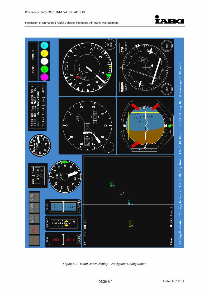
Preliminary Study CARE INNOVATIVE ACTION
Integration of Unmanned Aerial Vehicles into future Air Traffic Management
Date: 10.12.01page 67
Figure 6-2 - Head Down Display – Navigation Configuration

Preliminary Study CARE INNOVATIVE ACTION
Integration of Unmanned Aerial Vehicles into future Air Traffic Management
Date: 10.12.01page 68
6.2.2 Extended Air Defence Testbed
The Extended Air Defence Testbed Simulator provides a scenario simulation which could be
typically used for the flight planning and operation control of a UAV. The tool has an
establised link to the MILSIM environment also. As such this tool features many different
modes for investigation into different areas of flight conduction. With respect to questions
concerning the data link (e. g. antenna masking effects, etc.) and the situational awareness
concerning the identification of other related traffic, e. g., the tool provides information which
is based on models which have been verified by test data for real systems in most cases.
The tools provides different modes of displaying information. A conventional view to the
overall scenario similar to the infomation displayed to ATC controller is supported by the tool
as well as the view from a position of an airborne observer as shown in Figure 6-3.
Figure 6-3 – Test-Simulation with MALE-UAV in Conjunction with other Traffic

Preliminary Study CARE INNOVATIVE ACTION
Integration of Unmanned Aerial Vehicles into future Air Traffic Management
Date: 10.12.01page 69
7 References
[ 1] UAV to get language in FAA Regulations by Leona C. Bull
(http://www.aerotechneurs.Com) downloaded 26.09.2001
[ 2] Highlights of FAA/NASA Joint University Program for Air Transportation
Research (JUP)
(http://act 250.tc.foa.gov/jup/high lights) downloaded 26.09.2001
[ 3] Commercial High Altitude Unpiloted Aerial by Joanne, Irene Gabrywawicz
Remote Sensing. Some Legal Considerations
(http://www.space.edu) downloaded 26.09.2001
[ 4] Commercial UAV Operations in Civil Airspace by Laurence Newcome
www.adroit.com / www.navforum.com
[ 5] First UAV Atlantic crossing
http://www.dsto.defence.gov.an downloaded 24.09.2001
[ 6] Discussion Area 1 – UAV operations and mission planning and tasking
Minutes discussion area 4: Airspace Management and Traffic Deconfliction
http://www.far.org downloaded 25.09.2001
[ 7] “Send in the drones”,
Science and technology article in “The Economist”, November, 10th 2001
[ 8] Strategic Consulting and Market Research for the Aerospace and Defence
industry, Frost & Sullivan Aerospace & Defense,
www.unmannedaircraft.com
[ 9] intentionally left blank
[10] Range Safety Criteria For Unmanned Air Vehicles
Document 323-99
by Range Commanders Council (Range Safety Group)
[11] Unmanned Air Vehicle Operations in UK Airspace – Guidance (Version 1.0)
Directorate of Airspace Policy
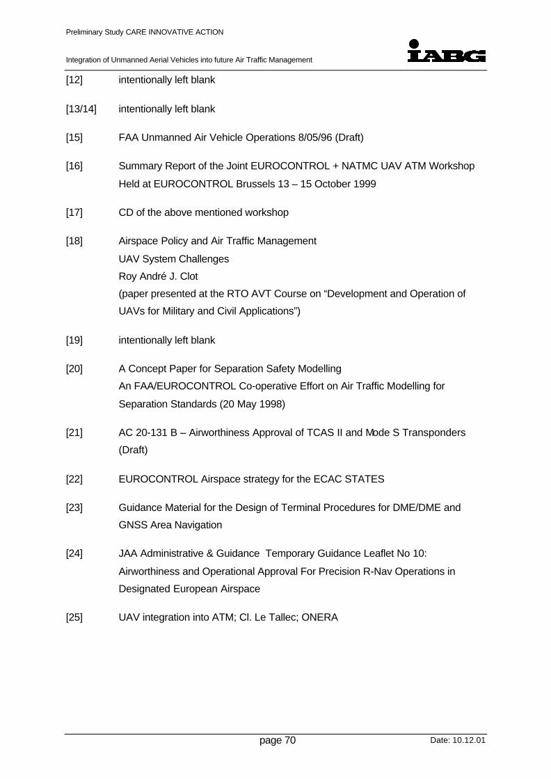
Preliminary Study CARE INNOVATIVE ACTION
Integration of Unmanned Aerial Vehicles into future Air Traffic Management
Date: 10.12.01page 70
[12] intentionally left blank
[13/14] intentionally left blank
[15] FAA Unmanned Air Vehicle Operations 8/05/96 (Draft)
[16] Summary Report of the Joint EUROCONTROL + NATMC UAV ATM Workshop
Held at EUROCONTROL Brussels 13 – 15 October 1999
[17] CD of the above mentioned workshop
[18] Airspace Policy and Air Traffic Management
UAV System Challenges
Roy André J. Clot
(paper presented at the RTO AVT Course on “Development and Operation of
UAVs for Military and Civil Applications”)
[19] intentionally left blank
[20] A Concept Paper for Separation Safety Modelling
An FAA/EUROCONTROL Co-operative Effort on Air Traffic Modelling for
Separation Standards (20 May 1998)
[21] AC 20-131 B – Airworthiness Approval of TCAS II and Mode S Transponders
(Draft)
[22] EUROCONTROL Airspace strategy for the ECAC STATES
[23] Guidance Material for the Design of Terminal Procedures for DME/DME and
GNSS Area Navigation
[24] JAA Administrative & Guidance Temporary Guidance Leaflet No 10:
Airworthiness and Operational Approval For Precision R-Nav Operations in
Designated European Airspace
[25] UAV integration into ATM; Cl. Le Tallec; ONERA

Preliminary Study CARE INNOVATIVE ACTION
Integration of Unmanned Aerial Vehicles into future Air Traffic Management
Date: 10.12.01page 71
8 Appendix A – Tables of UAV
In this Appendix representative UAV for the different UAV classes (0 to 3) are provided. In
particular there are four tables:
• Table A1 – “Class 0”This table shows a representative selection of UAV with a weight of less than 25 kg.
• Table A2 – “Class 1”This table shows a representative selection of UAV with a weight ranging from 25 kg to500 kg.
• Table A3 – “Class 2”This table shows a representative selection of UAV with a weight ranging from 501 kgto 2000 kg.
• Table A4 – “Class 3”This table shows a representative selection of UAV with a weight of more than 2000 kg.
8.1 Explanation of data fields and used abbreviations
• Link TypesThe link-types are divided in
• short wave
• micro wave
• satellite
• analogue
• digital
• ApplicationFor the application type three abbreviations are used:
• TC: Telecommand
• TM: Telemetry
• TV: Television
• Operating Frequency Range
• HF: 1-30 MHz
• VHF / UHF: 30-1000MHz
• L- / S-Band: 1-2 GHz
Preliminary Study CARE INNOVATIVE ACTION
Integration of Unmanned Aerial Vehicles into future Air Traffic Management
Date: 10.12.01page 72
• C-Band: 5 GHz
• X-Band: 10 GHz
• Ku-Band: 15 GHz
• Antenna Type
• Narrow Beam
• Omni Directional
• Link ProtectionThere is a wide variety of possible link protections, some are listed below:
• Redundancy
• Frequency Hopping (FHSS)
• Directed narrow Beam Antennas
• Direct Sequence Spread Spectrum (DSSS)
• Channel Coding
• Protocols
• CRC
• Data ProtectionThere is a variety of possible data protections, some are listed below:
• Encryption
• Authentication
The abbreviation “N / A” means that information on this particular point / item is not availableor not regarded as proved to be consistent or correct.

Preliminary Study CARE INNOVATIVE ACTION
Integration of Unmanned Aerial Vehicles into future Air Traffic Management
Date: 10.12.01page 73
Table A1: Representative UAV “Class 0” (below 25 kg)
Name Manufacturer NationMax
Weight[kg]
MaxSpeed[kts]
MaxAltitude
[ft]
MaxClimbRate[fpm]
MaxTask
Radius[nmi]
Endurance
[hrs]Data-link Navigation,
Guidance
Lift/PropulsionSystem;Launch &Recovery
Status
Javelin BAI Aerosyst. USA 10 60 3000 6 2 LOS (UHF+L)(C2 & video)
GPS, remotecontrol (VFR)
Fixed wing,piston engine;L: hand or
bungeeR: skid
P
Pointer AeroVironment USA 4.5 40 1000 600 4 0.4(nickel
cadmiumbattery)
LOS(C2 & video)
GPS pre-prog.& remote con
Fixed wing,electric motor;L: handR: deep stall &
belly land
P
Scout 2000 EMT Germany 3 45 1000 3 0.5(nickel
cadmiumbattery)
LOS(C2 & video)
GPS pre-prog.& remote con
Fixed wing,electric motor;L: handR: deep stall &
belly land
D
Conversion of Dimensions: km/h = 1.8532 kts, kg = 0.4536 lbs; ft = 0.3048 m, nmi = 1.8520 km
Data-link: Abbreviations:C2: command & control (up- & down-link) n/a: data not availablevideo: real-time TV, imagery and payload data (down-link) AV Air VehicleFrequency: UHF, L-band C-band. Ku-band, X-band LOS Line of sight
BLOS Beyond line of sightTake-off and Landing IFF transponder for identification (friend or foe)
L: Launch System, e.g. rocket booster, catapult, wheeled DL tracking tracking of the AV (azimuth & elevation) by data link antennaR: Recovery/Landing SystemVTOL Vertical takeoff and landingTOL Takeoff and landingStatus:D: DevelopmentP: ProductionR: Research

Preliminary Study CARE INNOVATIVE ACTION
Integration of Unmanned Aerial Vehicles into future Air Traffic Management
Date: 10.12.01page 74
Table A2: Representative UAV “Class 1” (25 - 500 kg)
Name Manufacturer NationMax
Weight[kg]
MaxSpeed[kts]
MaxAltitude
[ft]
MaxClimbRate[fpm]
MaxTask
Radius[nmi]
Endur-ance[hrs]
Data-linkNavigation,Guidance
Lift/PropulsionSystem;Launch &Recovery
Status
Propeller propulsion system with internal combustion (piston or rotary) or turbo-shaft engines Typical Mission Radius < 100 nmi
Camcopter SchiebelElectronics
Austria 65 55 990 6 6 LOS (C-band)(C2 & video)
INS + DGPS,pre-prog. &remote control
VTOL, convent.rotor system,(1) piston eng.
P
CL-327(enhancedSentinelCL-227)
Bombardier Canada 350 85 18000 1500 60 6 LOS (C)(C2 & video)
INS + GPS,pre-prog. &remote control
VTOL,coax-rotor, (1)turbo-shafteng.
P
Crecerelle(AVSpectre)
SAGEM France 140 130 11000 40 4 LOS(C2 & video)
GPS (DGPS),pre-prog. &remote con,IFF (Mode IIIC)
Fixed wing,(1) piston eng.;L: catapult,R: parachute
or skid
P
Cypher Sikorsky USA 135 80 5000 20 2.5 LOS (C-band)(C2 & video)
INS + GPS,pre-prog. &remote control
VTOL, ductedcoax-rotor,(1) rotary eng.
D
Exodrone BAI Aerosyst. USA 40 110 10000 2.5 LOS (UHFup-link, L-band down-link)C2 & video
DGPS, pre-prog. & remotecontrol
Fixed wing,(1) piston eng.,L: catapultR: skid, net or
parachute
P
Eye-View IAI Israel 150 110 15000 20 6 LOS(dual C2 &single video)
GPS, pre-prog.& remote con
Fixed wing,(1) piston eng.,wheeled TOL
P
Fox AT2 CAC Systems France 115 > 100 13000 40 5 LOS(C2 & video)
INS + DGPS,pre-prog. &remote control,
Fixed wing,(1) piston eng.,L: catapultR: parachute,
P

Preliminary Study CARE INNOVATIVE ACTION
Integration of Unmanned Aerial Vehicles into future Air Traffic Management
Date: 10.12.01page 75
Name Manufacturer NationMax
Weight[kg]
MaxSpeed[kts]
MaxAltitude
[ft]
MaxClimbRate[fpm]
MaxTask
Radius[nmi]
Endur-ance[hrs]
Data-linkNavigation,Guidance
Lift/PropulsionSystem;Launch &Recovery
Status
belly skidHermes 450 Silver Arrow Israel 450 100 23000 900 > 150
(w comrelay)
24 LOS (C/L)(dual C2 &video)
GPS, pre-prog.& remote con,redundant elect& avionics
Fixed wing,(2) rotary eng.,wheeled TOL
D
KZO(Brevel)
STN ATLAS(Eurodrone)
Germany(FR/GE)
150 100 13000 800 50 3.5 LOS (Ku)(C2 & video)
INS + GPS,pre-prog. &remote control,DL tracking
Fixed wing,(1) piston eng.,L: boosterR: parachute
D
LUNAX-2000
EMT Germany 30 70 13000 600 30 3 LOS (C)(C2 & video)
DGPS, pre-prog. & remotecontrol
Fixed wing,(1) piston eng.,L: catapultR:parachute
D
Mart Mk II Altec Ind. France 110 120 10000 1000 40 4 LOS(C2 & video)
remote controlbased on videoand GPS
Fixed wing,(1) piston eng.,L: catapultR: parachute,
belly skid
P
Mirach 26 Meteor CAE Italy 200 120 11000 590 50 6 LOS(C2 & video)
GPS/autopilot,pre-prog. &remote con
Fixed wing,(1) piston eng.,L: boosterR: parachute
P
Outrider AlliantTechsystems
USA 220 125 15000 1600 100 5 LOS (C)(C2 & video)
INS + GPS,pre-prog. &remote controlIFF (Mode IIIC)
Fixed wing,(1) piston eng.,wheeled TOL(autoland)
Can-celled1998
Pathfinder AeroVironment USA 250 30 70000 16 Fixed wing,solar powered,wheeled TOL
R
Phoenix GEC-MarconiAvionics
UK 180 90 > 6000 40 5 LOS (J)(C2 & video)
(n/a)pre-prog. &remote control
Fixed wing,(1) piston eng.,L: catapultR: parachute
P

Preliminary Study CARE INNOVATIVE ACTION
Integration of Unmanned Aerial Vehicles into future Air Traffic Management
Date: 10.12.01page 76
Name Manufacturer NationMax
Weight[kg]
MaxSpeed[kts]
MaxAltitude
[ft]
MaxClimbRate[fpm]
MaxTask
Radius[nmi]
Endur-ance[hrs]
Data-linkNavigation,Guidance
Lift/PropulsionSystem;Launch &Recovery
Status
Pioneer Pioneer UAV(AAI/IAI)
USA 200 100 12000 800 100 5 LOS (C+UHF)(C2 & video)
GPS pre-prog.& remote con,IFF (Mode IIIC)
Fixed wing,(1) piston eng.,L: wheeled or
catapultR: wheeled w
tailhook ornet
P
Ranger Orlikon-Contraves
Switzer-land
270 120 15000 750 90 5 LOS (UHF +Microwave)(C2 & video)
GPS, pre-prog.& remote con
Fixed wing,piston eng.,L: catapultR: skid auto-
land
P
Raven FlightRefuelling Ltd.
UK 85 110 14000 50 4 LOS(C2 & video)
GPS, pre-prog.& remote con
Fixed wing,(1) piston eng.,L: catapultR: parachute,
belly skid
D
RPG Midget- MkII
- MkIII
TechMent(VTOL) Sweden 50
90
70
80
30
40
3
4
LOS (C+UHF)(C2 & video)
INS + GPS,pre-prog. &remote control
Gyroplane(VTOL+fixed wing)conv. rotor,(1) piston eng.,near vertical orwheeled TOL
P
SearcherMk II
IAI Israel 420 110 20000 110 15 LOS(dual C2 &single video)
GPS,pre-prog. &remote control
Fixed wing,(1) rotary eng.,wheeled TOL
P
Shadow200
AAI USA 150 120 15000 70 5 LOS (C+UHF)dual C2 &single video,IFF Mode IIIC
GPS, pre-prog.& remote con,DL tracking
Fixed wing,(1) rotary eng.,L: rail or wheelR: wheel with
tailhook, or
P

Preliminary Study CARE INNOVATIVE ACTION
Integration of Unmanned Aerial Vehicles into future Air Traffic Management
Date: 10.12.01page 77
Name Manufacturer NationMax
Weight[kg]
MaxSpeed[kts]
MaxAltitude
[ft]
MaxClimbRate[fpm]
MaxTask
Radius[nmi]
Endur-ance[hrs]
Data-linkNavigation,Guidance
Lift/PropulsionSystem;Launch &Recovery
Status
parachuteShadow600
AAI USA 270 110 16000 110 14 LOS (C+UHF)dual C2 &single video,
GPS, pre-prog.& remote con,DL tracking
Fixed wing,(1) rotary eng.,wheeled TOL
P
Skyeye BAE Systems(USA)
USA 350 110 15000 750 80 10 LOS(C2 & video)
INS+GPS,remote control,video tracking
Fixed wing,(1) rotary eng.,L: catapultR: parachute,
belly skid
P
Spectre II NorthropGrumman &Meggitt TargetSystems
USA/UK 160 140 13000 80 6 LOS(C2 & video)
GPS, pre-prog.& remote con,RF tracking
Fixed wing,(1) piston eng.,L: catapultR: belly skid or
parachute
P
Sperwer SAGEM France 320 130 17000 80 4 LOS (Ku-band) videodown-link
INS + GPS,pre-prog. &remote control
Fixed wing,(1) piston eng.,L: catapultR: parachute
P
Propulsion: TurbojetTypical Mission Radius < 200 nmi
CL 289 EADS Dornier,Bombardier,SAT
GermanyCanadaFrance
240 400 10000 5000 100 0.5 LOS (onlydown-link forIR-video)
Gyro’s & GPS,radar doppleraltimeter &navigation syst
Cross wing,(1) turbojet engL: boosterR: parachute
P
Mirach 150 Meteor CAE Italy 340 400 29000 5000 200 1.2 LOS(C2 & video)
GPS/autopilot,pre-prog. &remote control
Fixed wing,(1) turbojet engL: booster or
air launchedR: parachute
P
Sperwer HV(highvelocity)
SAGEM France 400 400 30000 250(w comrelay)
1.5 LOS (Ku)(C2 & video)
INS + GPS,pre-prog. &remote control
Fixed wing,(1) turbojet eng
Demo

Preliminary Study CARE INNOVATIVE ACTION
Integration of Unmanned Aerial Vehicles into future Air Traffic Management
Date: 10.12.01page 78
Table A3: Representative UAV “Class 2” (501 - 2000 kg)
Name Manufacturer NationMax
Weight[kg]
MaxSpeed[kts]
MaxAltitude
[ft]
MaxClimbRate[fpm]
MaxTask
Radius[nmi]
Endur-ance[hrs]
Data-linkNavigation,Guidance
Lift/PropulsionSystem;Launch &Recovery
Status
Altus GeneralAtomics
USA 1000 100 45000 24 LOS (C-band) INS + GPS,pre-prog. &remote control
Fixed wing,(1) piston eng. +1-stage turbo-charger,wheeled TOL
P
A160Hummingbird
FrontierSystems
USA 1800 30000 24 VTOL, hingelessrigid rotor,(1) piston eng.
Demo
Dragon Fly(CanardRotor/Wing)
Boeing USA 810 400 10000 150 4 INS + GPS,pre-prog. &remote control
VTOL, jetdrivenrotor/wing,(1) low-bypassturbofan engine
Demo
Eagle 1 EADS/IAI France,Israel
1200 110 20000 500 24 LOS &SATCOM
Fixed wing,(1) piston eng.,wheeled TOL
Demo
Eagle-Eye Bell Helicopter USA 1000 200 20000 110 8 LOS (C+UHF)dual up (C2)& single down
Pre-prog. &remote control,
VTOL+fixedwing, tiltrotor,(1) turboshaftengine
Demo
Fire ScoutModel 379
NorthropGrumman,Ryan
USA 1150 135 20000 110(250withcom
relay)
6 LOS (TCDL)(Ku+UHF/VHF) (C2 &video)
INS + GPS,pre-prog. &remote control,IFF transpond.,RF tracking
VTOL, conv.rotor system, (1)turboshaft eng.(automatic VTOLon land & ship)
D(Navy)

Preliminary Study CARE INNOVATIVE ACTION
Integration of Unmanned Aerial Vehicles into future Air Traffic Management
Date: 10.12.01page 79
Name Manufacturer NationMax
Weight[kg]
MaxSpeed[kts]
MaxAltitude
[ft]
MaxClimbRate[fpm]
MaxTask
Radius[nmi]
Endur-ance[hrs]
Data-linkNavigation,Guidance
Lift/PropulsionSystem;Launch &Recovery
Status
I-Gnat(improvedGnat 750)
GeneralAtomics
USA 700 110 25000 1000 200(w comrelay)
40 LOS (C)(4.4-5 / 5.2-5.8 GHz)(dual C2 &dual video)
GPS (INSoptional), pre-prog. & remotecontrol,IFF (Mode IIIC)
Fixed wing,(1) pistonengine,wheeled TOL
P
Hermes1500
Silver Arrow Israel 1500 >130 30000 900 > 150(w comrelay)
30 LOS (C/L)(dual C2 &video)
GPS, pre-prog.& remote con,redundant elect& avionics
Fixed wing,(2) piston eng.+ turbocharger,wheeled TOL
D
Heron IAI Israel 1100 120 30000 110(150
w comrelay)
36 LOS(dual C2 &dual video)
GPS (optionINS), pre-prog.& remote con,redundant FCS
Fixed wing,(1) piston eng.+ turbocharger,wheeled TOL
P
Hunter IAI & TRW IsraelUSA
725 110 15000 750 110(150
w comrelay)
12 LOS (C-band,(4.4-5.8 GHz)(dual C2 &dual video)
GPS, pre-prog.& remote cont.,redundant elect& avionics,IFF (Mode IIIC)
Fixed wing,(2) piston eng.,wheeled TOL
P
Perseus B Aurora Flight USA 1100 250 65000 > 3000(withSat-com)
24 LOS &SATCOM(option)
GPS, pre-prog.& remote cont
Fixed wing,(1) piston engwith 3-stageturbocharger,wheeled TOL
Demo

Preliminary Study CARE INNOVATIVE ACTION
Integration of Unmanned Aerial Vehicles into future Air Traffic Management
Date: 10.12.01page 80
Name Manufacturer NationMax
Weight[kg]
MaxSpeed[kts]
MaxAltitude
[ft]
MaxClimbRate[fpm]
MaxTask
Radius[nmi]
Endur-ance[hrs]
Data-linkNavigation,Guidance
Lift/PropulsionSystem;Launch &Recovery
Status
Predator GeneralAtomics
USA 1000 110 25000 800 400(w comrelay orSatcom)
40 LOS (C-band)SATCOM(Ku+UHF)C2 & video
INS + GPS,pre-prog. &remote control,IFF (Mode IIIC)
Fixed wing,(1) piston eng,wheeled TOL
P
Seamos EADS Dornier Germany 1120 90 12000 1000 110 4.5 LOS (C2 &video)Ku 1-10 Mbps,UHF 10 Kbps),BLOS (C2) HF1Kbps
INS + GPS,pre-prog. &remote control
VTOL,coax-rotor, (1)turboshaft eng,(automatic VTOL
on ships)
Defi-nition
CML-UAV(cruisemissile likeUAV)
EADS Germany 1400 600(Mach0.9, SL
20000 550 3 LOS &LEO Satcom(C2 & video),terrain ref.navigation
GPS & INS,pre-prog. &remote control,terrain/imageref. navigation
Sweep wing,(1) turbojet orlow-bypassturbofan eng.,L: air launched
or boosterR: parachute
Study

Preliminary Study CARE INNOVATIVE ACTION
Integration of Unmanned Aerial Vehicles into future Air Traffic Management
Date: 10.12.01page 81
Table A4: Representative UAV “Class 3” ( above 2000 kg)
Name Manufacturer, NationMax
Weight[kg]
MaxSpeed[kts]
MaxAltitude
[ft]
MaxClimbRate[fpm]
MaxTask
Radius[nmi]
Endur-ance[hrs]
Data-linkNavigation,Guidance
Lift/PropulsionSystem;Launch &Recovery
Status
DarkStar(Tier IIIminus)
LockheedMartin /Boeing
USA 3900 300 50000 2000 500 12 LOS (X-band+ UHF)SATCOM(Ku+UHF)all C2 & video
INS + GPS,pre-prog. &remote control,IFF (Mode IIIC)
Fixed wing,stealth design,(1) turbofanengine,wheeled TOL
Can-celled1999
Eagle 2 EADS France 3600 250 45000 500 20 LOS &SATCOM
Fixed wing,(1) turboprop
Study
GlobalHawk(Tier II plus)
NorthropGrumman(TeledyneRyanAeronautical)
USA 11600 350(Mach
0.6,@ alt)
65000 3400 3000 38 LOS (X-band+ UHF)SATCOM(Ku+UHF)all C2 & video
INS + GPS,pre-prog. &remote control,IFF (Mode I, II,IIIC, IV)
Fixed wing,(1) turbofanengine,wheeled TOL
Demo
Predator B GeneralAtomics
USA 3000 200 50000 >2000 1000 32 LOS (C-band,)SATCOM(Ku+UHF)C2 & video
INS + GPS,pre-prog. &remote control,IFF transpond.
Fixed wing,(1) turbopropengine,wheeled TOL
Demo
X-45SEADUCAV(US Airforce)
Boeing USA 6800 600(Mach
0.9, SL)
45000 n/a 650 3 LOS +SATCOM
INS + GPS,pre-prog. &remote control,autonomousmission phases
Fixed wing,stealth design,(1) low-bypassturbofan eng.with thrustvectoring,wheeled TOL
Demo
X-47UCAV-NPegasus(US Navy)
NorthropGrumman
USA 4500 600(Mach
0.9, SL)
40000 n/a 600 12 Fixed wing,stealth design,(1) low-bypassturbofan eng,wheeled TOL
Demo

Preliminary Study CARE INNOVATIVE ACTION
Integration of Unmanned Aerial Vehicles into future Air Traffic Management
Date: 10.12.01page 82
Name Manufacturer, NationMax
Weight[kg]
MaxSpeed[kts]
MaxAltitude
[ft]
MaxClimbRate[fpm]
MaxTask
Radius[nmi]
Endur-ance[hrs]
Data-linkNavigation,Guidance
Lift/PropulsionSystem;Launch &Recovery
Status
on carrierGE UCAV(SEAD &strike)
EADS Germany 8200 550(Mach
0.85, SL)
LOS (X-/Ku-band, UHF),SATCOM(Ku+UHF),HF (BLOS)
Fixed wing,stealth design,(1) low-bypassturbofan eng,wheeled TOL
Study

Preliminary Study CARE INNOVATIVE ACTION
Integration of Unmanned Aerial Vehicles into future Air Traffic Management
Date: 10.12.01page 83
8.1.1 Illustration of the UAV Categorisation
A visualisation of the spread of main design parameters (e.g. mass, airspeed, etc.) versus
the Maximum Take-Off Weight (MTOW) is outlined for different UAVs. Figure A1 to Figure
A4 provide a visualisation of such data which were selected from Table A1 to A4.
In general these figures do not necessarily describe a functional relationship. As such the
figures describe the scatter in the main design parameter of different UAV. Note that not all
data for each UAV under consideration is available. As indicated by the figures the scatter for
a same mass class results from different design requirements for the UAV which also results
in different propulsion systems.
Figure A-1 - Comparison of max. Airspeed of different UAVs
Figure A-2 - Comparison of max. Altitude of different UAVs
0 200 400 600 800 1000 1200
60
80
100
120
140
160
180
200
Rotary Wing UAVs
Propulsion System: Piston / Rotary Engine Turboshaft
max
. Airs
peed
[kts
]
max. Take-Off weight [kg]0 2000 4000 6000 8000 10000 12000
0
50
100
150
200
250
300
350
400
450
500
550
600
Fixed Wing UAVs
Propulsion System: Piston / Rotary Engine Turboprop Turbojet / -fan Electric / Solar
max
. Airs
peed
[kts
]
max. Take-Off Weight [kg]
0 2000 4000 6000 8000 10000 120000
10000
20000
30000
40000
50000
60000
70000
80000
Fixed Wing UAVs
Propulsion System: Piston / Rotary Engine Turboprop Turbojet / -fan Electric / Solar
max
. Alti
tude
[ft]
max. Take-Off Weight [kg]0 250 500 750 1000 1250 1500 1750 2000
0
5000
10000
15000
20000
25000
30000
Rotary Wing UAVs
Propulsion System: Piston / Rotary Engine Turboshaft
max
. Alti
tude
[ft]
max. Take-Off Weight [kg]

Preliminary Study CARE INNOVATIVE ACTION
Integration of Unmanned Aerial Vehicles into future Air Traffic Management
Date: 10.12.01page 84
Figure A-3 - Comparison of max. Mission Radius of different UAVs
Figure A-4 - Comparison of max. Climb Rate of different UAVs in Sea Level
0 200 400 600 800 1000 12000
50
100
150
200
250
Rotary Wing UAVs
Propulsion System: Piston / Rotary Engine Turboshaft
max
. Mis
sion
Rad
ius
[nm
i]
max. Take-Off Weight [kg]0 2000 4000 6000 8000 10000 12000
0
500
1000
1500
2000
2500
3000
Fixed Wing UAVs
Propulsion System: Piston / Rotary Engine Turboprop Turbojet / -fan Electric / Solar
max
. Mis
sion
Rad
ius
[nm
i]
max. Take-Off Weight [kg]
0 2000 4000 6000 8000 10000 120000
1000
2000
3000
4000
5000
Fixed Wing UAVs
Propulsion System: Piston / Rotary Engine Turboprop Turbojet / -fan Electric / Solarm
ax. C
limb
Rat
e [ft
/min
]
max. Take-Off Weight [kg]
0 200 400 600 800 1000 12000
250
500
750
1000
1250
1500
Rotary Wing UAVs
Propulsion System: Piston / Rotary Engine Turboshaft
max
. Clim
b R
ate
[ft/m
in]
max. Take-Off Weight [kg]
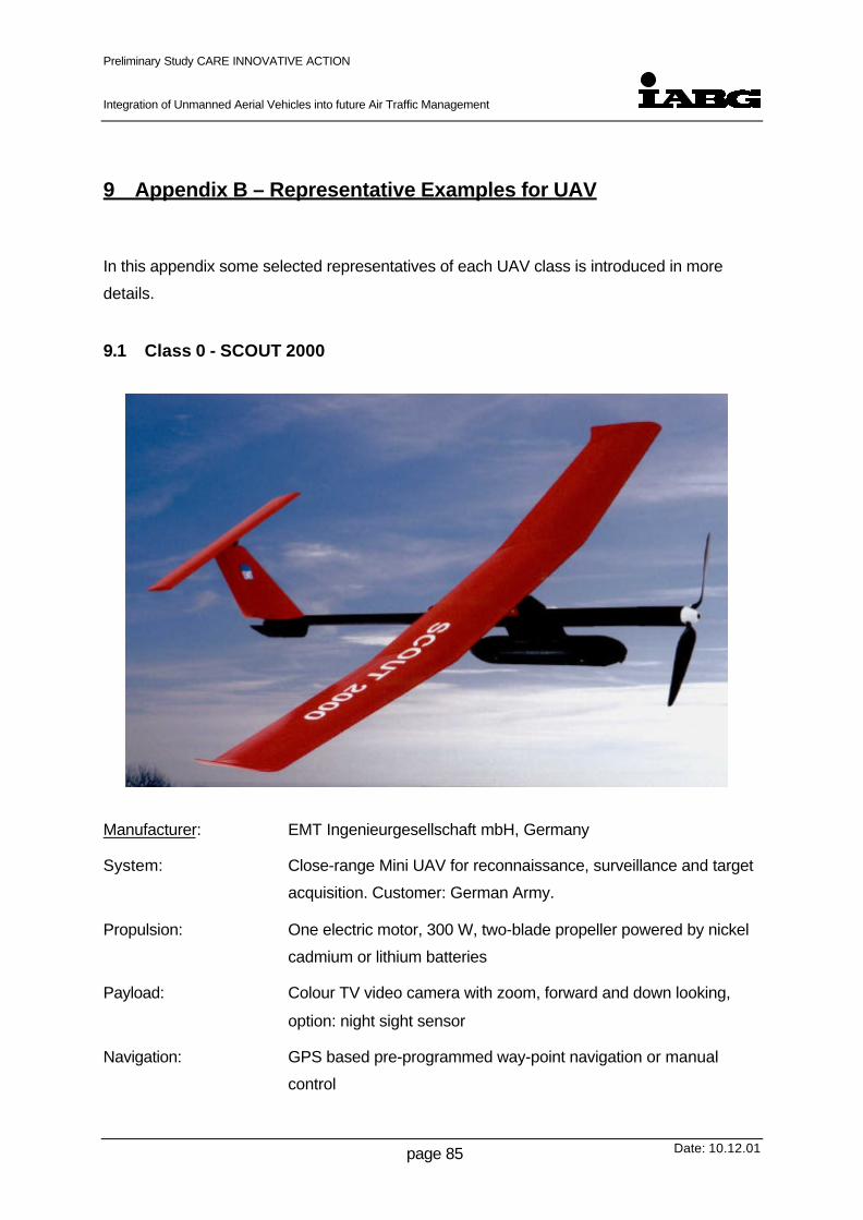
Preliminary Study CARE INNOVATIVE ACTION
Integration of Unmanned Aerial Vehicles into future Air Traffic Management
Date: 10.12.01page 85
9 Appendix B – Representative Examples for UAV
In this appendix some selected representatives of each UAV class is introduced in more
details.
9.1 Class 0 - SCOUT 2000
Manufacturer: EMT Ingenieurgesellschaft mbH, Germany
System: Close-range Mini UAV for reconnaissance, surveillance and target
acquisition. Customer: German Army.
Propulsion: One electric motor, 300 W, two-blade propeller powered by nickel
cadmium or lithium batteries
Payload: Colour TV video camera with zoom, forward and down looking,
option: night sight sensor
Navigation: GPS based pre-programmed way-point navigation or manual
control
Preliminary Study CARE INNOVATIVE ACTION
Integration of Unmanned Aerial Vehicles into future Air Traffic Management
Date: 10.12.01page 86
Datalink: LOS real time bi-directional datalink for command, control and
video
Launch & Recovery: Hand start and deep stall to belly landing
Control Station: Portable, laptop-like control station for command, control and video
display
Technical Data:
Takeoff Weight: 3 kg
Wingspan: 5 ft
Length: 5 ft
Payload: 1 kg
Fuel: Batteries
Flight Altitude: 100 ft – 1000 ft
Speed: 25 kts – 50 kts
Mission Radius: 3 nmi
Endurance: 0.5 hrs (nickel cadmium) or 2 hrs (lithium batteries))

Preliminary Study CARE INNOVATIVE ACTION
Integration of Unmanned Aerial Vehicles into future Air Traffic Management
Date: 10.12.01page 87
9.2 Class 1 - KZO (Brevel)
Manufacturer: STN ATLAS Elektronik GmbH, Germany
System: Short-range Tactical UAV for surveillance, target acquisition &
designation and battle damage assessment. Customer: German
Army.
Propulsion: One two-stroke, two-cylinder 30 hp piston engine, F&S/Schrick,
two-blade pusher propeller
Payload: Zeiss Ophelios gimbal mounted, stabilized IR-sensor with zoom,
forward, down and side looking. Options: communication jammer
(UAV Mücke) or signal detection/analysis (UAV Fledermaus)
Navigation: INS/GPS based pre-programmed way-point navigation and remote
control, navigation backup: tracking by the high precision narrow
beam data-link antenna on ground (rho/theta)
Datalink: LOS real time bi-directional Ku-band datalink, high jamming
resistance, (uplink for vehicle & sensor control, downlink for IR-
video and telemetry data)
Launch & Recovery: Rocket booster start and parachute / airbag landing
Control Station: Ground Control Station (GCS) with three work stations:
– one for mission planning, vehicle control and guidance,
– one for real time image exploitation and target acquisition,

Preliminary Study CARE INNOVATIVE ACTION
Integration of Unmanned Aerial Vehicles into future Air Traffic Management
Date: 10.12.01page 88
– one for target verification and tactical communication of the
commander.
The GCS is linked to the separate data-link ground terminal by a
robust fibre optical cable and contains a full mission sensor and
flight data recorder
Technical Data:
Takeoff Weight: 150 kg
Wingspan: 11 ft
Length: 7 ft
Payload: 30 kg
Fuel: 25 kg MOGAS
Flight Altitude: 1000 ft – 13000 ft
Speed: 60 kts – 100 kts
Max Climb Rate: 800 fpm
Mission Radius: 50 nmi
Endurance: 3.5 hrs

Preliminary Study CARE INNOVATIVE ACTION
Integration of Unmanned Aerial Vehicles into future Air Traffic Management
Date: 10.12.01page 89
9.3 Class 1 - OUTRIDER
Manufacturer: Alliant Techsystems Inc., USA
System: Short-range Tactical UAV for reconnaissance, surveillance and
target acquisition. Designed for US Army, Marine Corps and Navy
Propulsion: One 50 hp rotary engine UEL AR801R, two-blade pusher propeller
Payload: Gimbal mounted, stabilised EO/IR-sensor with zoom, forward,
down and side looking. Options: SAR (growth)
Navigation: INS/GPS based pre-programmed way-point navigation and remote
control, GPS auto-land system
Datalink: LOS real time bi-directional C-band analogue data-link (digital
growth), bandwidth 20 MHz with embedded 19.2 kbps C2 &
telemetry channel (up-link for vehicle & sensor control, down-link
for IR-video and telemetry data)
Launch & Recovery: Wheeled takeoff and landing on unprepared runways and large
ship decks
Control Station: Ground Control Station with two work stations:
– one for mission planning, vehicle control and guidance,
– one for real time image exploitation, target acquisition and
tactical communication.

Preliminary Study CARE INNOVATIVE ACTION
Integration of Unmanned Aerial Vehicles into future Air Traffic Management
Date: 10.12.01page 90
Technical Data:
Takeoff Weight: 220 kg
Wingspan: 13 ft
Length: 11 ft
Payload: 27 kg
Fuel: 35 kg AVGAS/MOGAS
Flight Altitude: up to 15000 ft
Speed: 60 kts – 120 kts
Max Climb Rate: 1600 fpm
Mission Radius: 100 nmi
Endurance: 5 hrs

Preliminary Study CARE INNOVATIVE ACTION
Integration of Unmanned Aerial Vehicles into future Air Traffic Management
Date: 10.12.01page 91
9.4 Class 2 - PREDATOR
Manufacturer: General Atomics Aeronautical Systems Inc., USA
System: Medium-range Endurance UAV (beyond line-of-sight with SAT-
COM) for reconnaissance, surveillance, target acquisition
/designation, electronic warfare, communication relay and signal
intelligence (SIGINT). Customer: US Department of Defence
Propulsion: One four-stroke, four-cylinder fuel injected 100 hp Rotax 914
piston engine with two-blade variable-pitch pusher propeller
Payload: Gimbal mounted, stabilised EO/IR-sensor with zoom, forward,
down and side looking, laser range-finder / designator and SAR.
Options: SIGINT and jam equipment, communication relay
Navigation: INS/GPS based pre-programmed way-point navigation and remote
control, IFF transponder Mode IIIC, VHF/UHF radio for ATC voice
relay
Datalink: Real time bi-directional C-band LOS data-link (20 MHz bandwidth),
UHF and Ku-band SATCOM (64 kbps up-link for vehicle & sensor
control, 1.5 Mbps down-link for EO/IR imagery, SAR and telemetry
data)
Launch & Recovery: Conventional wheeled takeoff and landing
Control Station: Ground Control Station with two work stations:
– one for mission planning, vehicle control and guidance,
– one for real time image exploitation, target acquisition and

Preliminary Study CARE INNOVATIVE ACTION
Integration of Unmanned Aerial Vehicles into future Air Traffic Management
Date: 10.12.01page 92
tactical communication.
Technical Data:
Takeoff Weight: 1050 kg
Wingspan: 49 ft
Length: 27 ft
Payload: 200 kg
Fuel: 300 kg AVGAS/MOGAS
Flight Altitude: up to 25000 ft
Speed: 60 kts – 110 kts
Max Climb Rate: 800 fpm
Mission Radius: 400 nmi
Endurance: 40 hrs

Preliminary Study CARE INNOVATIVE ACTION
Integration of Unmanned Aerial Vehicles into future Air Traffic Management
Date: 10.12.01page 93
9.5 Class 3 - Global Hawk
Manufacturer: Northrop Grumman, Teledyne Ryan Aeronautical, USA
System: Long-range, high altitude, long endurance UAV (beyond line-of-
sight with SATCOM) for reconnaissance, surveillance signal
intelligence (SIGINT) and communication relay. Customer: US Air
Force
Propulsion: One Allison Rolls-Royce AE 3007H turbofan engine (bypass ratio
5) rated at 7050 lbF sea level static thrust
Payload: SAR/MTI and high resolution electro-optical camera & infrared (3-5
µm) sensor. Both sensors are gyro-stabilised (3 mrad) and gimbal
mounted to allow down and side looking. The SAR sensor
provides spot and wide-area search mode operation and the
EO/IR sensors are looking through a common long range zoom
optical system (6 ft focal length, 11 inch aperture diameter). Future
payloads include SIGINT and communication relay equipment

Preliminary Study CARE INNOVATIVE ACTION
Integration of Unmanned Aerial Vehicles into future Air Traffic Management
Date: 10.12.01page 94
Navigation: INS/GPS based pre-programmed way-point navigation and remote
control, IFF transponder Mode I, II, IIIC and IV,
Data-link: Multiple real time bi-directional data-links:
Line-of-sight: UHF (9.6/9.6 kbps) and X-band (200kbps/137Mbps)
LOS data-links
Beyond line-of-sight: UHF (9.6/9.6 kbps) and Ku-band (200kbps/
48Mbps) SATCOM
Command and Control through all data-links (UHF 9.6 kbps,
X-band LOS and Ku-band SATCOM 200 kbps),
EO/IR/SAR imagery through X-band LOS (137 Mbps) or Ku-band
(48 Mbps) STACOM down-links
Self Defence: Threat warning receiver , onboard jammer, towed decoy
(repeater/deception transmitter)
Launch & Recovery: Conventional wheeled takeoff and landing
Control Station: Ground Control Stations:– Launch and Recovery Element (LRE) with two operators for vehicle control during takeoff, approach and landing and communication with ATC (shelter size 8 x 8 x10 ft),– Mission Control Element (MCE) with 5 operator places for mission planning, vehicle control and guidance, sensor control, EO/IR/SAR image exploitation and communication to air commander and ATC (shelter size 8 x 8 x 24 ft).
Technical Data:
Takeoff Weight: 11600 kg
Wingspan: 116 ft
Length: 45 ft
Payload: 900 kg
Fuel: 6650 kg Heavy Fuel (JP-8)
Flight Altitude: 50000 ft - 65000 ft
Speed: 340 kts at high altitude
Max Climb Rate: 3400 fpm
Mission Radius: 3000 nmi
Endurance: 38 hrs (20 hrs at 3000 nmi)

Preliminary Study CARE INNOVATIVE ACTION
Integration of Unmanned Aerial Vehicles into future Air Traffic Management
Date: 10.12.01page 95
10 Appendix C - Examples of Datalinks
10.1 UAV “Mücke”
The Mücke UAV is a small military system with a high degree of flight autonomy, used for
jamming missions in the VHF frequency range and higher. As this spectrum cannot be used
for the data link, UAV control and monitoring data are transferred via HF, which provides a
data rate of 1 Kbps.
Tasks of the control link are:
• Mission plan update
• Position request & reporting
• Technical status
• Jammer control
Mücke: Link Characteristics
Link Type Analogue Microwave Data Link, 2 parallel channels
Application TC / up-link (Mission Plan Update, Jammer Control, UAV-StatusRequest, Position Request);
TM / down-link (UAV-Status, Position Reporting)
Communication Mode semi duplex
Operating FrequencyRange
HF
Bandwidth/Data Rate 1 Kbps
Link Range < 220 NM
Antenna Type Horizontal Dipole Antenna
Link Protection FHSS
Data Protection N / A
(Transmitter Power) 30 Watts
ATC N / A

Preliminary Study CARE INNOVATIVE ACTION
Integration of Unmanned Aerial Vehicles into future Air Traffic Management
Date: 10.12.01page 96
10.2 UAV KZO / BREVEL
KZO/BREVEL: Link Characteristics
Link Digital Microwave Data Link; 3 channels
Application Channel 1: TC ( Up-link);
Channel 2: TM (Down-link);
Channel 3: TV (Down-link)
Communication Mode full duplex on all channels
Operating FrequencyRange
KU-Band
Bandwidth / Data Rate TC: (N / A) / 10 Kbps
TM: (N / A) / 10 Kbps
TV: (N / A) / 10 Mbps
Link Range > 80 NM / LOS
Antenna Type 2-axis directed Narrow Beam
Link Protection Directed narrow Beam Antenna; DSSS; FHSS; Interleaving
Data Protection Error Recognition / Correction by FEC-Codes
(Transmitter Power) self adaptive
ATC N / A

Preliminary Study CARE INNOVATIVE ACTION
Integration of Unmanned Aerial Vehicles into future Air Traffic Management
Date: 10.12.01page 97
10.3 UAV PIONEER
The Pioneer has two links:
• a main up- / down-link for Command & Control, B/W-video and Telemetry
• a secondary up-link for Command & Control data
Pioneer: Link 1 Link 2
Link Digital (N / A) Microwave DataLink
Digital (N / A) Short wave DataLink
Application TC (Up-link)TV [B/W-Video] (Down-link)TM (Up ink)
Secondary Up-link for TC
Communication Mode simplex (N / A) simplex (N / A)
Operating FrequencyRange
C-Band;4.43 – 4.94 GHz selectable in5 MHz steps
UHF;420 – 450 MHz
Bandwidth / Data Rate 36,36 Mhz/10 MHz (N / AMbps)
600KHz / 7.317Kbps
Link Range • 7 NM (real time video) /LOS
• 18 – 20 NM (C2, TM,non real time video) /LOS
18 – 20 NM
Antenna Type Omni Directional Omni Directional
Link Protection Redundant UHF-Link for TC
Data Protection None (N / A) None (N / A)
(Transmitter Power) (N / A) (N / A)
ATC N / A
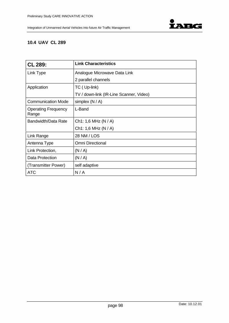
Preliminary Study CARE INNOVATIVE ACTION
Integration of Unmanned Aerial Vehicles into future Air Traffic Management
Date: 10.12.01page 98
10.4 UAV CL 289
CL 289: Link Characteristics
Link Type Analogue Microwave Data Link
2 parallel channels
Application TC ( Up-link)
TV / down-link (IR-Line Scanner, Video)
Communication Mode simplex (N / A)
Operating FrequencyRange
L-Band
Bandwidth/Data Rate Ch1: 1,6 MHz (N / A)
Ch1: 1,6 MHz (N / A)
Link Range 28 NM / LOS
Antenna Type Omni Directional
Link Protection, (N / A)
Data Protection (N / A)
(Transmitter Power) self adaptive
ATC N / A

Preliminary Study CARE INNOVATIVE ACTION
Integration of Unmanned Aerial Vehicles into future Air Traffic Management
Date: 10.12.01page 99
10.5 UAV Global Hawk
Global Hawk has four independent data communication systems:
• L3 Communications Integrated Communication System as Ku-Band SATCOM
• Command & Control System as UHF SATCOM
• Command & Control System as UHF LOS
• Common Data Link as Microwave LOS
Global Hawk:(Tier II plus)
Link 1 Link 2 Link 3 Link 4
Link Digital SatelliteData Link
Digital SatelliteData Link (DoDUHF Satellite)
DigitalMicrowave DataLink
Digital Shortwave Data Link
Application • TC / to Sat.(UAVstatus)
• TV / to Sat.(ThreatInfo,ImageryData)
• TC/to Sat.(UAVstatus)
• TV/to Sat.(ThreatInfo)
• TC/fromSat.
Common DataLink:
• TC / down-link
• TV / down-link(Imagerydata,ThreatInfo)
TM / down-link
• TC (up-link)
• Voicerelay (up-link)
• UAV-Status(downl-ink)
• Voicerelay(downl-ink)
Communication Mode half duplex(N / A)
half duplex(N / A)
half duplex(N / A)
half duplex(N / A)
Operating FrequencyRange
Ku-Band UHF X-Band UHF
Bandwidth/Data Rate Return Link: 3 -69 MHz / 1.5 –48 Mbps
Command Link:260 KHz / 200Kbps
25KHz / 9.6Kbps
Return Link: 137MHz / 137 Mbps(48 used)
Command Link:64 MHz / 200Kbps
25 KHz / 9.6Kbps
Link Range dep. on satellitecoverage
dep. on satellitecoverage
LOS LOS (<270 NM)
Antenna Type (N / A) (N / A) (N / A) (N / A)
Link Protection Redundant UHF-Link for TC
Data Protection (N / A)
(Transmitter Power) (N / A) (N / A) (N / A) (N / A)
ATC Transponder Mode 1, 2, 3 C, 4, IFF

Preliminary Study CARE INNOVATIVE ACTION
Integration of Unmanned Aerial Vehicles into future Air Traffic Management
Date: 10.12.01page 100
10.6 UAV Predator
Predator:(Tier II)
Link 1 Link 2 Link 3
Link Type Digital Satellite DataLink
Digital Satellite DataLink
Analogue MicrowaveData Link
Application • TC / from Sat.(MissionUpdate,PayloadControl)
• TV / to Sat.(Imagery)
• TM / to Sat.(AV-Status)
(N / A) • TC / up-link
Communication Mode (N / A) (N / A) (N / A)
Operating FrequencyRange
Ku-Band UHF C-Band
Bandwidth/Data Rate Return Link: 5 MHz /1,544 MbpsCommand Link: 9MHz / n * 64 Kbps
(N / A) 20MHz / 20 MHz
Link Range dep. on satellitecoverage
(N / A) LOS
Antenna Type (N / A) (N / A) (N / A)
Link Protection (N / A)
Data Protection (N / A) (N / A) (N / A)
(Transmitter Power) (N / A) (N / A) (N / A)
ATC Transponder Mode 3 C, IFF

Preliminary Study CARE INNOVATIVE ACTION
Integration of Unmanned Aerial Vehicles into future Air Traffic Management
Date: 10.12.01page 101
11 Appendix D – Airspace Categorisation
This appendix contains a brief description of current airspace categorisations and a simplified
long term future categorisation which is planned by EUROCONTROL [22]. Furthermore
some basic description for the utilisation of european airspace were introduced.
11.1 Air Traffic in European Airspace
11.1.1 Basic Terms
In this chapter some basic terms for the further discussion are introduced and explained as
well as the impact on civil UAV operation.
11.1.1.1 Meteorological Conditions
Basically there are two possible meteorological conditions which can occur:
• Instrument Meteorological Conditions (IMC) and
• Visual Meteorological Conditions (VMC).
VMC is prevailing if certain values for visibility and cloud ceiling are given, respectively if a
certain distance to clouds, both lateral and vertical, can be maintained. Whereas IMC is
prevailing if any of the values mentioned above are not given or can not be maintained.
These two meteorological conditions are based on the human eyesight. Thus, they are not
applicable for the control of the UAV itself, but they are decisive with respect to other traffic.
UAVs operate entirely independent on these meteorological conditions.
11.1.1.2 Flight Rules
There are two basic kinds of flight rules:
• Instrument Flight Rules (IFR) and
• Visual Flight Rules (VFR).
Flights can be conducted under one or a mix of these flight rules. Flights under VFR (VFR-
flights) have to be conducted in VMC, that means separation and collision avoidance are
mostly based on “see and avoid”. Flights under IFR (IFR-flights) may be conducted either
under VMC or IMC. In IMC the collision avoidance is primarily based on other means than

Preliminary Study CARE INNOVATIVE ACTION
Integration of Unmanned Aerial Vehicles into future Air Traffic Management
Date: 10.12.01page 102
“see and avoid”. In the first approach, UAVs have inherently to be operated as IFR-flights. To
operate UAVs in an environment, where at least some other traffic operates according VFR
rules, mainly based on “see and avoid”, requires special measures, addressed further down.
11.1.2 Airspace Classification
The following part describes the different categories of the present airspace structure.
Thereafter the envisaged future airspace structure is outlined.
11.1.2.1 Present Categories of Airspace
In Europe the airspace is structured basically in the classes A to G. However, the airspace
structures in the European countries differ as well as the applied categories of airspace.
Furthermore, each country may apply slight deviations from ICAO regulations, listed in the
respective AIP (Aeronautical Information Publication.)
For the further discussion, the following simplified structure of airspace is used; it keeps track
of the classes A to G, which can be summarised as follows:
• Controlled airspaceThis airspace is in the primary responsibility of ATM, however, not all traffic in thisairspace is under positive radar control. In controlled airspace IFR-flights and VFR-flights are possible, collision avoidance is in the responsibility of ATC (IFR) and theaircrews (VFR). UAVs have to operate under the responsibility of ATC, VFR flights ofmanned aircraft have to be informed accordingly about UAV flights.
• Uncontrolled AirspaceA relatively small portion of European airspace is uncontrolled airspace. Traffic in thisairspace is normally not in contact with ATM-authorities and therefore mostly unknownto ATC. All flights are supposed to be VFR-flights and collision avoidance is in theresponsibility of the aircrews. UAVs have to avoid uncontrolled airspace. If this is notfeasible, all other traffic has to be informed accordingly, e.g. by NOTAM.
• Special Use AirspaceAll airspace which is used for special purposes, as for example military airspace. Trafficin this airspace is under radar control and must be known to ATC. Most of today’s UAVoperations are restricted to special use airspace.
11.1.2.2 Future Categories of Airspace
The long term Eurocontrol airspace strategy for the ECAC states [22] focuses on only three
categories of airspace in the future. Long term plans will reduce the number of categories to
two. The future categorisation is based on knowledge of traffic and its intent rather than on
the discrimination between controlled and uncontrolled airspace:

Preliminary Study CARE INNOVATIVE ACTION
Integration of Unmanned Aerial Vehicles into future Air Traffic Management
Date: 10.12.01page 103
• Airspace NAll traffic and all intentions are known (e. g. an UAV in a pre planned flight for radio/TVtransmission relay)
• Airspace KAll traffic is known, but not all intentions (e. g. an UAV in a flight for environmentalcontrol, area of flight known, but detailed routing according actually detected pollutionIn this case, the UAV has to report its position repeatedly to ATC)
• Airspace UUnknown traffic environment. UAV should avoid this airspace . If this is not feasible,ATC must inform all other traffic, e.g. by NOTAM. Basically, the same conditions applyas for uncontrolled airspace.
11.2 Utilisation of European Airspace
The consequences for the operation of UAV within the respective airspace structure are
discussed in a general manner. Respective overviews are given at the end of the chapter. As
in most parts of this report, the aspects of equipment mass, volume (both affecting especially
small UAV capability considerably) and economic aspects are not addressed.
Any vehicle flying under Instrument Flight Rules is under constant surveillance of ATC.
Vehicles flying VFR are not necessarily under constant surveillance of ATC, but in certain
areas can be subjected to various degrees of surveillance, see below. Further down an
overview is given taking into account the ICAO airspace categories and a Eurocontrol future
traffic environment model.
11.2.1 Controlled Airspace
11.2.1.1 Flights within Controlled Airspace in IMC
All air vehicles, manned aircraft as well as UAVs, flying in IMC, have to fly according IFR and
have to rely on ATC and navigational aids (NAVAIDS) for routing and separation.
Separation and de-confliction is provided by ATC on the basis of:
• Usage of the Air Route Network
• Radar coverage
• time over reporting points
• fixed procedures (e.g. holdings)
• voice communication (data link communication in progress)
• Automated ground based systems, acting in the background, as Short Term ConflictAlert (STCA of the German ATS provider DFS) and others
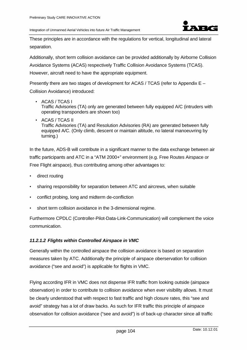
Preliminary Study CARE INNOVATIVE ACTION
Integration of Unmanned Aerial Vehicles into future Air Traffic Management
Date: 10.12.01page 104
These principles are in accordance with the regulations for vertical, longitudinal and lateral
separation.
Additionally, short term collision avoidance can be provided additionally by Airborne Collision
Avoidance Systems (ACAS) respectively Traffic Collision Avoidance Systems (TCAS).
However, aircraft need to have the appropriate equipment.
Presently there are two stages of development for ACAS / TCAS (refer to Appendix E –
Collision Avoidance) introduced:
• ACAS / TCAS ITraffic Advisories (TA) only are generated between fully equipped A/C (intruders withoperating transponders are shown too)
• ACAS / TCAS IITraffic Advisories (TA) and Resolution Advisories (RA) are generated between fullyequipped A/C. (Only climb, descent or maintain altitude, no lateral manoeuvring byturning.)
In the future, ADS-B will contribute in a significant manner to the data exchange between air
traffic participants and ATC in a “ATM 2000+” environment (e.g. Free Routes Airspace or
Free Flight airspace), thus contributing among other advantages to:
• direct routing
• sharing responsibility for separation between ATC and aircrews, when suitable
• conflict probing, long and midterm de-confliction
• short term collision avoidance in the 3-dimensional regime.
Furthermore CPDLC (Controller-Pilot-Data-Link-Communication) will complement the voice
communication.
11.2.1.2 Flights within Controlled Airspace in VMC
Generally within the controlled airspace the collision avoidance is based on separation
measures taken by ATC. Additionally the principle of airspace oberservation for collision
avoidance (“see and avoid”) is applicable for flights in VMC.
Flying according IFR in VMC does not dispense IFR traffic from looking outside (airspace
observation) in order to contribute to collision avoidance when ever visibility allows. It must
be clearly understood that with respect to fast traffic and high closure rates, this “see and
avoid” strategy has a lot of draw backs. As such for IFR traffic this principle of airspace
observation for collision avoidance (“see and avoid”) is of back-up character since all traffic

Preliminary Study CARE INNOVATIVE ACTION
Integration of Unmanned Aerial Vehicles into future Air Traffic Management
Date: 10.12.01page 105
movements and positions of other traffic participants within the controlled airspace should be
well known. Basically the collision avoidance is based on separation measures taken by ATC
and additional/optinal on-board collision avoidance systems as mentioned above.
In addition to ATC provided separation measures and procedures VFR traffic has to rely on
the “see and avoid” strategy.
VFR traffic by night in controlled airspace requires at least similar surveillance as IFR-traffic.
In addition, for all VFR flights in controlled airspace, a transponder code is mandatory. Thus,
ATC is not restricted to primary radar alone. Furthermore, TCAS/ACAS devices support the
identification of traffic participants via the transponder signal. The transponder is also
required for all UAV flights in all drafts of UAV equipment. Appropriate small and lightweight
transponders are available on the market.
VFR Air traffic may use traffic information provided by the ATC-Info-Service, if available.
However, usage is not mandatory and info service is not available on a 24 hour basis.
Some degree of separation may be generated by following the non mandatory semi-circular
system.
VFR traffic is prohibited above FL 100, though exceptions are made under certain conditions,
which assure a secure level of control by ATC.
11.2.2 Uncontrolled Airspace
11.2.2.1 Flights within Uncontrolled Airspace in VMC
Uncontrolled airspace is not controlled by ATC and all flights of manned vehicles have to be
conducted under VFR. Therefore the air traffic basically has to detect and solve separation
conflicts by means of “see and avoid”. Additionally some of the aircraft have technical
means, for example transponders, to support in separation provision. However, this
additional equipment is presently not mandatory.
11.2.3 Special Use Airspace
Special Use Airspace (SUA) consists of Airspace of defined dimensions identified by an area
on the surface of the earth wherein activities must be confined because of their nature and/or

Preliminary Study CARE INNOVATIVE ACTION
Integration of Unmanned Aerial Vehicles into future Air Traffic Management
Date: 10.12.01page 106
wherein limitations may be imposed upon aircraft operations that are not a part of those
activities.
The different types of special use airspace are:
• Alert Area Airspace
Alert Area Airspace may contain a high volume of pilot training activities or an unusual
type of aerial activity, neither of which is hazardous. Pilots of participating aircraft as
well as pilots transiting the area are equally responsible for collision avoidance. The
same is true for UAVs.
• Controlled Firing Area
Controlled Firing Area is airspace wherein activities are conducted under conditions so
controlled as to eliminate hazards to non participating aircraft and UAV and to ensure
the safety of persons and property on the ground.
• Military Operations Area
Military Operations Area (MOA) is established outside of Class A airspace area to
separate or segregate certain non hazardous military activities from IFR traffic and to
identify for VFR traffic where these activities are conducted.
• Prohibited Area
Prohibited Area, Airspace within which no person may operate an aircraft without the
permission of the using agency.
• Restricted Area
In Restricted Areas the flight of aircraft, while not wholly prohibited, is subject to
restriction. Most restricted areas are designated joint use and IFR/VFR operations in
the area may be authorised by the controlling ATC facility when it is not being utilised
by the using agency. Restricted areas are depicted on en route charts.
• Warning Area
Warning Area- A is airspace of defined dimensions extending from 3 nautical miles
outward from the coast of the United States, that contains activity that may be
hazardous to non participating aircraft. The purpose of such warning area is to warn
non participating pilots of the potential danger. A warning area may be located over
domestic or international waters or both.

Preliminary Study CARE INNOVATIVE ACTION
Integration of Unmanned Aerial Vehicles into future Air Traffic Management
Date: 10.12.01page 107
12 Appendix E - Collision Avoidance
This appendix contains considerations concerning Collision Avoidance issues of UAV.
12.1 ACAS / TCAS / ETCAS
Short term collision avoidance is provided, if applicable, additionally by:
• ACAS / TCAS I between fully equipped A/C generates traffic advisories only (Intruderswith operable transponders are shown too)
• ACAS / TCAS II between fully equipped A/C generates traffic advisories and resolutionadvisories. (Only climb, descent or maintain altitude, no lateral manoeuvring.)
• ETCAS (Enhanced TCAS) is a military follow-on development of TCAS, showing allTCAS features and additional functionalities. ETCAS may be especially suitable forUAV due to its enlarged and reshaped warning area.
• Several other active or passive Collision Avoidance devices are available on themarket, mostly intended for smaller and lighter aircraft / helicopters and hence lesssophisticated than ACAS / TCAS
With respect to TCAS/ACAS and UAV the following essential facts (being also true for the
other Collision Avoidance devices) must be clearly understood.
• In TCAS I as well as in TCAS / ACAS II, the display of the horizontal situation i.e. trafficand intruders is mainly thought to help the aircrew in visual perception and tracking oftraffic and intruders, if meteorological and physiological conditions permit.
• Because the azimuth measurement of the direction (bearing) is of reduced accuracy (inTCAS I it is 14 degrees), the TCAS / ACAS display is not suitable for lateral avoidancemanoeuvring. Only altitude information is reliable if Mode C is operable. TCAS II /ACAS II algorithms and resolution advisories are based only on vertical manoeuvres(climb, descent, level keeping and some changes in strength).
• TCAS / ACAS does not incorporate any interface to cockpit automation, but is basedmerely on the avoidance action performed by the cockpit crew.
NOTE:Reference [21], TCAS II Airworthiness Approval, among other parts, reads as follows:“The TCAS II resolution advisory (RA) algorithms are based on the pilot initiating theinitial 0.25 g acceleration manoeuvre within approximately 5 seconds. Pilot response isexpected within approximately 2 – ½ seconds if an additional RA is issued. (Theincrease rate and rate reversal RAs are based on a .35 g acceleration manoeuvre.)Because of these requirements and the rate limits of the auto pilots, all RA responsesmust be hand-flown and not with the auto pilot or auto throttles engaged.”
(Consequences for UAV are discussed above in depth. To cope with the performances of the
UAV certain Resolution Advisories may be inhibited, not to exceed critical limits.)

Preliminary Study CARE INNOVATIVE ACTION
Integration of Unmanned Aerial Vehicles into future Air Traffic Management
Date: 10.12.01page 108
TCAS/ACAS display can contribute to safety of an UAV but is far from being the solution for
UAV in general airspace. The requirements of avoidance manoeuvres exceed the rate limits
of present auto pilots of manned aircraft and UAV. Responses to resolution advisories must
be manually flown, auto-throttles disengaged. An aggravating factor is that TCAS, in contrary
to transponder Mode S, is not even mandatory for all IFR traffic
12.2 ADS-B
ADS-B relies on the exact 3-dimensional position and other information (speed, intent etc.
according to the appropriate “surveillance level”). Thus ADS-B exchanges information
suitable for 3-dimensional conflict probing, co-operative long-, mid- and short-term de-
confliction / collision avoidance. ADS-B can be used and is intended to be used as basis for
automation of manoeuvring.
The collision avoidance algorithms must take into account the different performances of UAV
and manned aircraft, to be fully applicable for UAV. Technical considerations concerning
automatic collision avoidance are given further down in Appendix F – Separation Safety.
12.3 Avoidance of Collision with Terrain
Collision avoidance with terrain can be given in a separate redundant manner as in manned
aircraft, by GPWS / TAWS equipment. These items as well do not contain any interface to
automation. Due to the fact, that the usage of civil airspace will not contain extremely low
level flight, terrain collision avoidance is not an “immediate action necessary” item.
Comparison of UAV position with terrain data can be done in the UCS during flight and
during flight planning as well.

Preliminary Study CARE INNOVATIVE ACTION
Integration of Unmanned Aerial Vehicles into future Air Traffic Management
Date: 10.12.01page 109
13 Appendix F - Separation Safety
In this appendix the factors, affecting separation safety are listed and discussed with respect
to UAV operation. The factors are taken from “A Concept Paper For Separation Safety
Modelling”, subtitled “An FAA EUROCONTROL Co-operative Effort on Air Traffic Modelling
for Separation Standards” [20]. The structure of the factors is maintained throughout the
discussion in order to enhance cross reference to the original document.
The listed factors are valid for all kinds of separation provided by ATC (e.g. IFR from IFR and
IFR from VFR) and during ATM emergency procedures. Preliminary the factors are used to
look at possible operation of UAVs in commonly used airspace to give some preliminary
results for separation safety for UAV.
The structure of the factors is maintained throughout the discussion in order to enhance
cross reference to the original document [20].
In the left column, the factors of [20] are listed. In the right column, the factors are discussed
with respect to UAV operation. The discussion refers either to a single factor or to the
respective groups of factors.
FACTORS affecting separation safety DISCUSSION with respect to UAV
A - Relative aircraft positions and velocities (encounter geometry)
1. “Blind-flying” risk [factors that affect
risk – no intervention]
(a) Horizontal and vertical
positions and closing angles
(b) Aircraft velocities and
accelerations
(c) Climb/descent rates and
accelerations
(d) Vertical path separation at
crossing point
With respect to UAV these criteria, especially b, c and d are
influenced by performance, handling quality, control laws as
well as by the overall design concept of the respective UAV.
UAV may differ considerably from air transport traffic.
In case of a relatively slow flying UAV on an air route,
continuous risk of collision from behind is present (refer to
2.0 “TCAS / ACAS”).

Preliminary Study CARE INNOVATIVE ACTION
Integration of Unmanned Aerial Vehicles into future Air Traffic Management
Date: 10.12.01page 110
A - Relative aircraft positions and velocities (encounter geometry) contd.
2. Pilot intervention – factors that
affect timely pilot detection and
correction
(a) Closure rate Reflects the relative geometry between an air vehicle and
the separation inflicting UAV and depends from the general
situation, the performance and other internal factors. For
example if the UAV is co-ordinated into normal IFR traffic or
does it use special procedures or special separation minima
(b) Relative bearings and aspects
angles in relation to cockpit
field of view restrictions, the
horizon
(c) Rate of change of the above
angles (zero for linear collision
courses)
(d) Aircraft attitudes and ban
angles
(e) Meteorological conditions and
background conditions,
including location of the sun
(affecting ability to perceive
other aircraft and their relative
distance, velocity, and
trajectory)
(f) Natural lighting conditions
(e.g., day, night, dawn, dusk)
(g) Threat aircraft size, skin
colour, and lighting
(h) Condensation trails
(i) Empty visual field
(j) Night accommodation
Reflect the ability of the pilot in an aircraft to detect/see
another aeroplane as well as to detect the loss of
separation by visual perception.
In IMC, the pilot has no “natural” vision outside the aircraft.
Currently upcoming in the civil air transport business is syn-
thetic vision (enhanced vision) for e.g. the final approach,
generated by light intensifying sensors or IR-Sensors.
The UAV operator of an UAV never has a direct visibility out
of his UAV but is restricted merely to sensing if this is
provided. However, sensing allows to draw up different
scenarios:
Worst case :
no sensing and no direct situational awareness
Best case :
In the most favourable case, the UAV operator has
available a sensor-suite, which gives in a 3 dimensional
combined display a far better situational awareness with
respect to weather, range and field of view/regard than
direct eye sight:
• 360° horizontal/vertical
• sensing independent from visible light by radar, IR,
light intensifying, and other sensors, may be borrowed
from military seeker technology (e.g. UV spectrum)
• range finding supplemental to radar (laser range
finder)

Preliminary Study CARE INNOVATIVE ACTION
Integration of Unmanned Aerial Vehicles into future Air Traffic Management
Date: 10.12.01page 111
A - Relative aircraft positions and velocities (encounter geometry) contd.
2. Pilot intervention – factors that affect
timely pilot detection and correction
(contd.)
It must be fully understood, that the display for the UAV
operator must not give a real picture of other traffic and
obstacles, that means being like a vision system for
manned simulation. The display could show only
information necessary for the very purpose of collision
avoidance and others. The problem is the data link, the
capacity of which is limited. Sensor fusion and other tasks
must be done onboard to minimise data flow to the UCS.
On the ground, appropriate symbology will be processed
and displayed.
These techniques, in the research named some times
“synthetic vision” and envisaged as enhancement for
manned aircraft and UAV can also enhance the UAV
operation in unreserved public airspace with mixed IFR and
VFR traffic also in a high density environment. Furthermore
these comprehensive sensing techniques are the basis for
automatic collision avoidance with respect to all air traffic
and in consequence for a true autonomous and safe flight.
All air traffic comprises all sort of man made air traffic
(manned/unmanned aircraft down to ultra lights,
parachutes) as well as natural air traffic (bird strike risk).
On the other hand, “being seen and avoided” is essential in
the same way for VFR / IFR traffic, as long as a “naked”
human vision is involved. Certification requirement drafts
tend to address this fact by lighting and colour scheme. But
small and slender fuselages, as UAV have, are difficult to
acquire, even in bright colour scheme.
Remark: Giving UAV appropriate painting and lighting to
ease detection by aircrew is matter of certification
procedures and draft papers.
Though these techniques are ready to come, they are
not in the economic reach of the commercial air traffic,
no matter if manned or unmanned. With special respect
to UAV, the equipment mass and volume as well as
power consumption is of additional strong concern.

Preliminary Study CARE INNOVATIVE ACTION
Integration of Unmanned Aerial Vehicles into future Air Traffic Management
Date: 10.12.01page 112
A - Relative aircraft positions and velocities (encounter geometry) contd.
2. Pilot intervention – factors that affect
timely pilot detection and correction
(contd.)
(k) Party line
Party line (effect) is the ability to generate a mental picture
of the traffic situation merely by listening to the radio
communication between ATC and the respective air traffic
or between air traffic in the neighbourhood of the own
aircraft. Thus, situational awareness is enhanced. On the
other hand, excessive speech transmissions may degrade
human performance.
The upcoming data link communication will in principle
cause a loss of party line. The effect will be researched also
within CARE and should be checked with respect to UAV
operators of UAV.
Possible research issues are for example situational
awareness of UAV operator, needed to which extent; how
can party line be provided to UAV operators/operators; if
beneficial, skills needed by UAV operators to exploit party
line effect appropriately.
(l) Reliance on ground-based
surveillance and procedures
With respect to manned aircraft, this means that the crew in
an aircraft reduces vigilance, if they fly under radar
surveillance.
The UAV operator of an UAV has to rely in many aspects
completely on radar coverage. If other means of collision
avoidance are available these means can back up radar
coverage or complement radar coverage
Additionally the UAV operator of an UAV has to monitor the
flight status of the UAV to avoid deviations from the planned
and/or cleared flight path. (Like in ATC announcement,
automated procedures can be foreseen to detect small
deviations. Their sensitivity can be dependent from
airspace, e.g. higher in terminal area.

Preliminary Study CARE INNOVATIVE ACTION
Integration of Unmanned Aerial Vehicles into future Air Traffic Management
Date: 10.12.01page 113
A - Relative aircraft positions and velocities (encounter geometry) contd.
2. Pilot intervention – factors that affect
timely pilot detection and correction
(contd.)
(m) Cockpit workload, staffing,
automation, and procedures
(n) Flight crew training, skill,
teamwork
With respect to UAV, these items m deal with the whole topic of
MMI of the UCS and training of the respective crew to operate and
“fly” the UAV. These topics are partially addressed in the
certification of UAV and need further research, because the
operation in a civil airspace is not performed routinely by UAV
users until now.
Topics concerning the UCS with respect to ATC, MMI and
questions of training must be incorporated into the research
activities.
(o) TCAS/ACAS responsiveness,
affected for example by aircraft
bank angle
The influences of TCAS/ACAS responsiveness are
basically the same for manned an unmanned air vehicles.
The effects of size and form of fuselage of UAV must be
thoroughly checked for each type. It is assumed, that UAV
are equipped with the latest version of TCAS/ACAS in all
aspects.
3. ATC intervention – factors that
affect the probability of timely and
effective ATC intervention
(a) Air traffic service provided
(b) Climb/descent rate and
acceleration (affects ATC
computer projections)
(c) Horizontal velocity and
acceleration
(d) Turn rate and turn acceleration
(change in turn rate)
(e) Airspace complexity
(f) Traffic complexity and density
(g) Proximity to an airspace
boundary (e.g., SUA)
(h) ATC co-ordination (e.g.,
involving an aircraft in hand-off
or point-out status)
These items affect the probability of timely and effective
ATC intervention with respect to UAV too. Additionally a
delay factor may be expected due to data link
communication and lack of direct control capability of the
UAV operator of the UAV.
Due to proven ATC procedures no procedures will be
changed because of rare UAV flights. But UAV-flights
should be kept in mind in course of changes, e.g. to ADS-B
Furthermore it must be thoroughly checked, which classes
of UAV (mainly performance, manoeuvrability, MMI delay)
are cleared into which airspace – categories and under
which circumstances.

Preliminary Study CARE INNOVATIVE ACTION
Integration of Unmanned Aerial Vehicles into future Air Traffic Management
Date: 10.12.01page 114
A - Relative aircraft positions and velocities (encounter geometry) contd.
3. ATC intervention – factors that affect
the probability of timely and effective
ATC intervention (contd.)
(i) Air traffic management tools
for reducing controller
workload and improving
controller intervention
capability
• Automated controller
planning tools including
trajectory projection, conflict
probe, and conflict
resolution.
• Automated out-of-
conformance alerts (3D and
may be 4D), which alert
ATC to any deviation of an
aircraft from its nominal
path.
• Controller display quality:
picture, information, and
presentation of information.
The automated planning tools or alerts should take the
presence of UAV into account. This begins with filing a flight
plan for each UAV flight, special transponder code and
direct data link between ATC and UAV operator.
On this basis, the automated tools should take into account
the performances of the respective UAV (coding filed with
the flight plan or/and down linked within the ADS-B
parameters, special criteria should be applied for the
automated tools).
Thus, for example, an alert could be given earlier than in
case of a manned aircraft.
Some research of the flight path accuracy must be done
with respect to ATM tolerances and separation. The same
is true for the whole topic of procedure design, especially
with respect to TMA procedures.
Principally 2 sets of data from an UAV can be exploited:
§ The surveillance data, gained by ATC, i.e. radar, or
ADS-B data
§ The relevant data (position, speed etc.) which are
exchanged between UAV and the respective UCS
(permission to exploit these set of data of military UAV
for civil ATC might be refused by a military operator).
By this procedure, relevant data of the UAV can be
gained without an explicit ADS-B requirement. This can
be helpful for the integration of UAV into the ATM.
However, the exploitation of the data by ATC needs
further research.
(j) Controller skill, training, and
teamwork
(k) Controller workload, staffing,
and procedures
A controller should not have to do other/different ATM-tasks
with respect to UAV then with respect to conventional air
traffic (e.g. controller should not be UAV operator of an UAV
when managing air traffic).
But the incorporation of UAV traffic will evoke changes and
need additional training of the controller.

Preliminary Study CARE INNOVATIVE ACTION
Integration of Unmanned Aerial Vehicles into future Air Traffic Management
Date: 10.12.01page 115
A - Relative aircraft positions and velocities (encounter geometry) contd.
4. Aircraft reaction – factors that affect
aircraft reaction time in response to
a needed manoeuvre
(a) Aircraft performance (including
manoeuvrability)
(b) Pressure and density altitude
(related to aircraft performance
and atmospheric conditions)
(c) Speed (e.g., relative to stall
speed, available thrust, etc.)
The reaction time of a response to a needed manoeuvre of
an UAV may differ significantly from a civil air transport (or
executive jet), according to conceptual design,
performance, control laws etc. Additional reaction time may
be needed on the communication way from ATC via link to
the UAV operator and continued from the UAV operator to
the UAV.
Of additional concerns is the MMI of UCS and the concept
of control of the UAV. Refer also to A2m, n, cockpit work
load, flight crew training.
(d) Climb/descent rate
(e) Attitude and bank angle
(f) Proximity to terrain
See also item in ref. D 3 “Aircraft –
Aeroplane / Power plant” below
The task of flying an air vehicle can be divided in 3 portions
of different gain:
• short term attitude control (stabilisation)
• mid term velocity and position control (guidance)
• long term course control (navigation).
In a properly designed and certified General Aviation
aeroplane, all 3 tasks can be fulfilled by a pilot,
sophisticated aeroplanes (Commercial Air Transports) have
automatic flight control systems, auto pilots and fly to a
great extent “automatically”. But despite these aids, also in
most recent aeroplane designs, the pilot can use a hand-
wheel or stick and hand-fly the aeroplane directly. In most
cases, the pilot is aided by fly-by-wire and appropriate
control laws (care free handling), which exploit the utmost
distant areas of the flight envelope. Thus a pilot would
respond to an urgent advise by ATC or even by a
TCAS/ACAS alert. This immediate and quick response may
not be possible in an UAV control station or could take more
time due to several reasons.

Preliminary Study CARE INNOVATIVE ACTION
Integration of Unmanned Aerial Vehicles into future Air Traffic Management
Date: 10.12.01page 116
A - Relative aircraft positions and velocities (encounter geometry) contd.
4. Aircraft reaction – factors that affect
aircraft reaction time in response to a
needed manoeuvre (contd.)
For UAV- systems (vehicle-data link-UCS) minimum
requirements criteria must be defined for reaction time,
comprising the whole sequence:
• initiation by ATC via data link to UAV operator
• UAV operator input via data link to UAV
• UAV reaction time, begin of requested manoeuvre
appropriate displacement, change of course etc. of
the UAV.
Sufficient reaction time can be assured by hand-flying in
combination with carefree handling or by setting auto pilots
with complete control authority available. Today, auto pilots
achieve for example roll rates of 5° per second in procedure
turns. This value is not suitable for any collision avoidance
manoeuvre, as mentioned before.
Remark:
Autonomous Flight is addressed separately, but must be
checked with respect to auto pilot rate limits. With respect to
TCAS/ACAS and ADS-B the remarks under chapter “Type
of airspace/controlled airspace in IMC” are valid too.
Excerpt from TCAS II Airworthiness Approval [21]
The TCAS II RA algorithms are based on the pilot initiating
the initial 0.25 g acceleration manoeuvre within
approximately 5 seconds. Pilot response is expected within
approximately 2 – ½ seconds if an additional RA is issued.
(The increase rate and rate reversal RAs are based on a
0.35 g acceleration manoeuvre.) Because of these
requirements and the rate limits of the auto pilots, all RA
responses must be hand-flown and not with the auto pilot or
auto throttles engaged.
To cope with the performances of the UAV certain
Resolution Advisories may be inhibited, no to exceed critical
limits.

Preliminary Study CARE INNOVATIVE ACTION
Integration of Unmanned Aerial Vehicles into future Air Traffic Management
Date: 10.12.01page 117
B - ATC rules and procedures, airspace structure
1. Hemispheric rules
2. Route structure, i.e., the use of
parallel or non-parallel ATS routes
and whether they are bi-directional
or uni-directional
3. Separation minima
(a) Horizontal
(b) Vertical
(c) How often values close to the
“official” separation minima are
used in practice.
These items describe a conventional airspace structure. For
civil purposes UAV may have to use this airspace structure
without disturbing the traffic flow. The new traffic
environment model of Eurocontrol is referenced on other
places, additional considerations concerning ATC
procedures are referenced at the end of B.
4. Flight planning
(a) Requirement to file flight plan
(b) Requirement to fly in
conformance to flight plan
(c) Requirement to cruise at
certain discrete altitudes –
Hemispheric rules
Mandatory filing of a flight plan can be found in almost alldrafts of UAV operating procedures in civil airspace. It mustcontain a hint that the respective vehicle is an UAV. Referto UCS. The flight planning of a civil UAV, and missionplanning of a military UAV (using civil airspace) mustcontain at least the same information concerning AIS asflight planning of a manned air vehicle, e.g. European AISData base, NOTAM etc. This data –base must containspecial information for UAV, if in the future it is found outthat info of this kind is to be spread (e.g. temporarilyrestricted air space for UAV, manned air vehicles only)should UAV operators or operators of UAV be informeddistinctly about other UAV operations / general informationabout UAV operation to all aviators.
In case of full data link loss the flight plan should addressadequate strategy for vehicle recovery.
An other topic of flight planning with potential effects to ATM
is the susceptibility of an UAV to weather influence, as
storms icing etc. These weather phenomena must be
incorporated into flight planning, tailored to the type of UAV
As for modern aircraft, especially military aircraft, the
planning of an UAV flight should contain detection of conflict
with detailed airspace structure and with terrain. So
planning errors could be minimised.

Preliminary Study CARE INNOVATIVE ACTION
Integration of Unmanned Aerial Vehicles into future Air Traffic Management
Date: 10.12.01page 118
B - ATC rules and procedures, airspace structure (contd.)
5. Requirement to obtain clearance
prior to altitude change
6. Positive control
7. Airspace complexity and flight path
geometry, including the following:
(a) Traffic demand pattern
(b) Number of aircraft at same
altitude
(c) Numbers and locations of
crossing tracks
(d) Amount of traffic operating on
opposite direction tracks
These items describe various ATC rules, procedures and
airspace structures. In the course of further research
including real time and fast time simulation, it must be found
out if the respective UAV operation can follow all these
current or future conditions. Some of the items are indirect
relation to an UAV operation
• diversity of traffic (7f)
• Take off of an UAV from a runway of a normal airport
will be time consuming (7h)
• Civil UAV operation will probably often be in
conjunction with special purposes and therefore
take place in TRA, SUA etc.(e.g. photo flight,
relay flight, environment control) (item 7i).
(e) Amount of traffic transitioning
altitudes
(f) Nature of the aircraft
population (i.e., the diversity of
traffic with respect to aircraft
performance and equipage,
such as the mix of various
speeds, climb performance,
and desired optimal flight
levels)
(g) Peak and average traffic
demands versus system
capacity
(h) Runway capacities and the
limitations of associated
ground services
• It must be checked, if UAV sustain the same
meteorological conditions as air transports or
executive jets (storms etc.). If this is not the case,
restrictions must be imposed and/or a certain among
of deviations from planned flight, caused by met
conditions, will be experienced. This will in turn lead
the higher ATC workload, traffic co-ordination effort
and may be emergencies of UAV (item 7j).
• Special airspace restrictions may be imposed
by the flight of civil UAV (relay station, environment
control etc.) and thus cause additional co-ordination
effort (item B10).
• Military operations in all aspects will be a great portion
of UAV traffic (e.g. B11).

Preliminary Study CARE INNOVATIVE ACTION
Integration of Unmanned Aerial Vehicles into future Air Traffic Management
Date: 10.12.01page 119
B - ATC rules and procedures, airspace structure (contd.)
(i) Any adjoining special use
airspace, airspace usage, and
types of activities including the
civil/military mix
(j) Regional meteorological
conditions (e.g., the
prevalence of convective
storms, etc.)
(k) Designated airspace
classification
8. Flow management capability (ability
to control traffic input to ATC)
(a) Strategic air traffic flow
management
(b) Tactical air traffic flow
management
(c) Ad hoc ATC “in trail”
restrictions or enhancements
(d) Procedural restrictions (e.g.,
by local operating procedures).
9. Special airspace restrictions
(a) Restricted airspace
(b) Special use airspace
(c) Traffic flow restrictions
(d) Noise abatement restrictions
10. Special situations
(a) Air shows(b) Other aviation-intensive events
(e.g., Olympic games)(c) Military exercises
(d) Formation flight
(e) Backup procedures
Special attention must be given to the whole complex of
procedure design. The most significant concern is given to
the terminal procedures for departure and arrival (SID and
STAR). Given, that the UAV is taking off and landing on an
airport together with GAT and commercial air transport, SID
and STAR or at least portions of it are the flight segments,
where traffic is mixing closely making effects of traffic
diversity show up most distinctly causing congestion and
delay. It is also the segment, where separation and
sequencing is the most demanding task. Caused by the
same effect, small single engine aircraft are banned from
several airports. The design guides and values for terminal
procedures must be reviewed as well as the performances
of the UAV-classes. Eventually the proven or new complex
procedures, possible due to P-RNAV and necessary due to
noise abatement and other environmental considerations,
cannot be followed adequately by UAV classification with
this respect should be available. The following table shows
the aircraft approach categories A – E according to the
speed. If the task of separating and sequencing the air
traffic cannot be fulfilled, the safe, orderly and expeditious
flow of air traffic finally is endangered by the UAV.
Eventually new design guidelines and finally procedures
must be generated for the UAV, given that the UAV are
landing and taking off according IFR. This assumption is a
reasonable one as long as the usage of civil airports is
assumed. Eventually different STAR and SID have to be
foreseen according to the respective performance of UAV.
An appropriate classification with this respect should be
available. The aircraft approach categories A – E according
to the speed are shown in the table at the of this appendix.

Preliminary Study CARE INNOVATIVE ACTION
Integration of Unmanned Aerial Vehicles into future Air Traffic Management
Date: 10.12.01page 120
C - Communication capability
1. Direct controller/pilot voice
communication (VHF/HF/SATCOM)
2. Indirect controller/pilot voice
communication (HF)
3. Controller/pilot data link
communication (CPDLC)
4. Controller/controller voice and
automated data link
communication, both inter and intra
ATS unit(s)
5. Data link between ground ATC
automation systems and aircraft
flight management computers
6. System availability, reliability, and
capacity
7. Backup systems and procedures
Communication Capability
With respect to UAV the communication capability differs
from manned air vehicles. In principle, 3 data links exist with
respect to ATM.
§ Data link between UAV and UCS (UAV operator)
§ Data link between UCS (UAV operator) and ATC. It
must be researched if pure data or pure voice alone are
sufficient. But given voice as most direct communication
and data link as valuable basic communication, both
should be available.
§ Surveillance data link between UAV, other air traffic and
ATC in an ADS-B-environment.
It should be researched if the data link from UAV to ATC
can contain also some information concerning technical
status of UAV.
The reporting of technical problems of a manned aircraft,
having consequences to ATC/ATM, is done by the aircrew
direct to ATC. In many cases, ATC knows about the
problem and actions before the ATC surveillance
(eventually automated) shows deviations or other problems.
Technical problems of an UAV are down-linked to the UCS
and afterwards passed over to ATC by the UAV operator.
This may be time consuming and cause considerable
delays.
The data links are vital for safe UAV operation and safe
UAV operation in civil airspace, therefore redundancy or low
MTBF are of great importance. (This is also reflected in at
least some of the certification paper drafts.)
Data link between ground ATC automation and aircraft flight
management computers will be replaced by data links from
the UAV as well as from the UCS to ATC automation
system (refer to C5).

Preliminary Study CARE INNOVATIVE ACTION
Integration of Unmanned Aerial Vehicles into future Air Traffic Management
Date: 10.12.01page 121
C - Communication capability
7. Backup systems and procedures
(contd.)
In the mid-term future and in the course of ADS-B technical
pre-conditions will be given, that ATC gains some influence
on the control of aircraft in some severe cases of
emergency. A clearance is issued by ATC, seen and
confirmed via CPDLC by the pilot and after this procedure
passed over automatically into the FMS. FMS sets auto
pilot appropriately and aircraft proceeds as cleared. The
same far future procedure can be planned for a
communication between ATC and UAV operator.
By this procedure, errors in understanding the clearance,
interpret the clearance or set a FMS/Auto pilot can be
avoided in case of air vehicles, no matter if manned or not.
D - Aircraft
1. Certification standards
(a) Airframe
(b) Power plant
(c) Systems
2. Maintenance [including manuals]
(a) Airframe
(b) Power plant
(c) Systems
Certification standards and maintenance procedures are
within the scope of appropriate drafts for UAV, also UAV
using civil airspace. Airframe inertia
3. Aeroplane/power plant (applies
for normal operation and
abnormal operation, e.g. loss of
engine, or failure of some
aeroplane systems)
Performances and manoeuvrability of UAV may cause
problems if deviating significantly from other air traffic. This
was discussed previously under item A4A

Preliminary Study CARE INNOVATIVE ACTION
Integration of Unmanned Aerial Vehicles into future Air Traffic Management
Date: 10.12.01page 122
D - Aircraft (contd.)
(a) Speed and altitude envelope of
the aeroplane type (This factor
may contribute to exposure
frequency in cruise operation
in a given airspace.)
(b) Climb and descent profiles
(speed/thrust/altitude profiles)
[may affect exposure
frequency in climb and
descent]
(c) Manoeuvre response
capability (e.g., to a controller
or TCAS/ACAS alert), such as:
• Engine spool up time
• Airframe inertia
• Rate of climb or descent
• Level acceleration /deceleration
(d) Aeroplane dimensions and
wake vortex profile
RVSM and other items as parallel runways draw up
possible interaction with wakes also en-route. This is the
same for UAV, especially if overall layout gives a higher
sensitivity
4. Aeroplane systems factors
(a) Navigation Sensor complement
• ADF
• VOR
• DME
• IRS (newer, strap-downinertial reference systems)
• INS (older, gimballedinertial reference systems)
• Loran
• Omega
• Satellite-based systemssuch as GPS, GLONASS
• Other

Preliminary Study CARE INNOVATIVE ACTION
Integration of Unmanned Aerial Vehicles into future Air Traffic Management
Date: 10.12.01page 123
D - Aircraft (contd.)
4. Aeroplane systems factors (contd.)
(b) Navigation systems
1) Navigation computersystems
2) Other, like-capability areanavigation (RNAV) systems(on other aircraft)
3) Navigation SystemPerformance§ Required navigation
performance (RNP)
§ Typical and non-typicalperformance (e.g.,MASPS/MOPS; RTCASC-181 documents)
§ Time-keeping accuracy§ Reliability/availability
§ Integrity§ Effects of more accurate
navigation
“Unfortunate”interaction of pilotblunder/altitude miss-assignment and moreaccurate navigation(i.e., a blunder wouldbe more likely to putone aircraft right ontop of anotherbecause of the moreaccurate horizontalnavigation providedby GPS).
In principle, all items apply to UAV (except the smaller
range of navigation sensors, UAVs will have only GPS/INS
in an UAV). Equipment of this sort has an inherent
capability to fulfil all future requirements of P-RNAV. On the
other hand, it must be checked, that the intended air route
is approved for an IFR flight based on P-RNAV only and
that the respective certification requirements allow IFR flight
with P-RNAV only.
Navigation System Performance must fulfil the
requirements for civil airspace and the RNP concept
established by the national authority. That means in turn,
these requirements must be reflected in the airworthiness
requirements for the UAV
[24] addresses the navigation performance for track
keeping accuracy.
It must be discussed, if for safety reasons higher
requirements of accuracy are necessary, which allow an
immediate detection of deviations by automated ATC
systems. The technical feasibility must be researched as
well.
(c) Communications capability
1) Voice communicationssystems
A) Commercial aircraft
- Required
communication
performance
- VHF systems (direct)
- HF systems (indirect)
Communication capability of data links is discussed in the
previous chapters. ACARS is not needed by UAV, it’s
function is performed by the data link between ATC and the
UAV operator. Between ATC and UCS voice
communication is absolutely necessary, fixed lines may
complement radio communication.

Preliminary Study CARE INNOVATIVE ACTION
Integration of Unmanned Aerial Vehicles into future Air Traffic Management
Date: 10.12.01page 124
D - Aircraft (contd.)
4. Aeroplane systems factors (contd.)
B) Military aircraft
C) General Aviation and
other aircraft
D) UHF
E) SATCOM
(communication via
satellite)
2) ADS-B3) ACARS
(d) Surveillance capability
1) Required surveillanceequipment performance
2) Air-ground transponder
A) Mode C transponder
B) Mode S transponder
Mode S with appropriate
level and surveillance
degree canal
C) Mode A transponder
3) TCAS/ACAS (Traffic Alertand Collision AvoidanceSystem/Airborne CollisionAvoidance System)
4) Advanced TCAS/ACAS
5) Automatic DependentSurveillance (ADS)
6) Cockpit display of aircrafttraffic information (CDTI)
With respect to UAV and as discussed earlier, TCAS/ACAS
is not the solution, only contribution to the problem.
Beside providing independence from primary radar echoes,
Mode-S-Transponders form together with TCAS/ACAS-
equipment the basis for collision avoidance. Mandatory
introduction of several levels of Mode S data link capability
is already planned, Mode S may also become the data link
for the future ADS-B.
TCAS/ACAS equipment and ADS-B provide independent
data link capability between air vehicles and between air
vehicles and ground. ADS-B is furthermore the basis for a
free flight environment, envisaged in the ATM 2000+
strategy.
ATM 2000 + provides direct routing, responsibility sharing
between ATC and aircrews (in the future also UAV
operators?), de-confliction and short term collision
avoidance.
The CDTI is the display of all the ADS-B data. TCAS/ACAS
provides a first step for a sense and avoid capability but is
by far not sufficient. VFR traffic in the controlled airspace is
normally equipped with TCAS/ACAS and some IFR traffic is
not equipped too.

Preliminary Study CARE INNOVATIVE ACTION
Integration of Unmanned Aerial Vehicles into future Air Traffic Management
Date: 10.12.01page 125
Latest TCAS/ACAS equipment offers greater detection
ranges, nearing ADS-B, incorporation of EGPWS/TAWS
(no resolution advisory which inflicts with terrain). Derived
from military equipment (e.g. ETCAS) the elliptical warning
box of TCAS/ACAS can be given a spherical form, so also
warning from behind can be given.
With respect to TCAS/ACAS, the performances of the
respective UAV must be matched with the TCAS/ACAS
models, eventually capability must be restricted because
resolution advisories cannot be followed.(Refer to A4.)
Generally the procedures, software, algorithms etc. must be
checked with respect to UAV operation. TCAS/ACAS and
ADS-B do not contain any automated collision avoidance.
All TCAS/ACAS advisories must be linked at least to the
UAV operator and followed by his/her action (refer to item
A4 concerning reaction time of an UAV).
(e) Backup systems and procedures
E - Ground/Satellite systems: Surveillance and Navigation
1. Surveillance capability
(a) Procedural dependent
surveillance
1) Content of pilot positionreports
2) Reporting intervals
(b) Automatic dependent
surveillance (ADS)
1) Basic update rate
2) Display accuracy; controller
display target position error
3) ADS contracts (e.g.,
increased reporting rate by
triggering events)
4) Sensor accuracy
5) System reliability
In principle all items of Ground/Satellite systems for
surveillance and navigation are of importance for UAV
operation.
In comparison to manned air vehicles the importance of a
single item may be changed considerably.

Preliminary Study CARE INNOVATIVE ACTION
Integration of Unmanned Aerial Vehicles into future Air Traffic Management
Date: 10.12.01page 126
E - Ground/Satellite systems: Surveillance and Navigation
1. Surveillance capability (contd.)
6) System availability
7) End-to-end
communications time
capabilities
(c) System coverage Independent
surveillance (radar)
1) Type of sensor (primary or
secondary)
2) Coverage area
3) Processing and associated
delays
4) Accuracy of measured
position after processing
A) Radar registration error
(Mosaic)
B) Slant-range error for
non-Mode C equipped
aircraft
5) Update rate
6) Display accuracy (error)
7) System reliability
8) System availability
9) Backup systems
2. Performance
(a) Accuracy
1) Automation-induced errors
(b) Reliability/availability
Concerning E2 Performance, the automation induced errors
must be looked over, because more automation and links
takes place from side of the UAV as direct input in ground
systems automated systems.
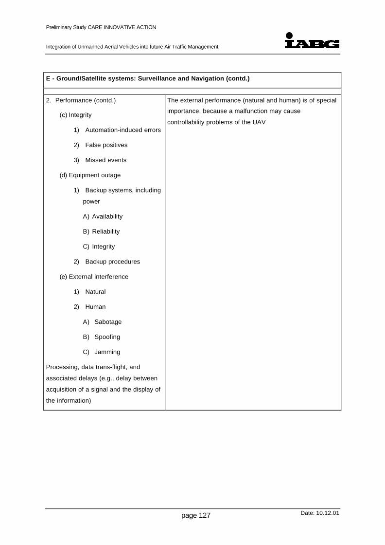
Preliminary Study CARE INNOVATIVE ACTION
Integration of Unmanned Aerial Vehicles into future Air Traffic Management
Date: 10.12.01page 127
E - Ground/Satellite systems: Surveillance and Navigation (contd.)
2. Performance (contd.)
(c) Integrity
1) Automation-induced errors
2) False positives
3) Missed events
(d) Equipment outage
1) Backup systems, including
power
A) Availability
B) Reliability
C) Integrity
2) Backup procedures
(e) External interference
1) Natural
2) Human
A) Sabotage
B) Spoofing
C) Jamming
Processing, data trans-flight, and
associated delays (e.g., delay between
acquisition of a signal and the display of
the information)
The external performance (natural and human) is of special
importance, because a malfunction may cause
controllability problems of the UAV

Preliminary Study CARE INNOVATIVE ACTION
Integration of Unmanned Aerial Vehicles into future Air Traffic Management
Date: 10.12.01page 128
F - Human performance
1. Flight crew performance/skill
(a) Monitoring/situational
awareness
(b) Crew co-ordination and
communication/Cockpit
Resource Management
(c) Controller/Pilot
communication/co-ordination
(also see section F.2.c. of this
outline)
(d) Response time
(e) Movement time
(f) Crew workload and vigilance
(g) Human error/human reliability
(h) Interaction with
hardware/software
automation/assistance
1) Displays
2) Warnings/advisories
A) TCAS
B) CDTI
(i) Certification standards
(j) Training
(k) Operator procedures, manuals
(l) Corporate culture
Concerning Human Performance/skill of a UAV operator, no
broad experiences seem to exist. The procedures
concerning error management in the cockpit may have
changed for a UAV operator.
Some facts can be derived from aircrew human research.
As mentioned before, the entire UAV system including UCS
must be considered

Preliminary Study CARE INNOVATIVE ACTION
Integration of Unmanned Aerial Vehicles into future Air Traffic Management
Date: 10.12.01page 129
F - Human performance (contd.)
2. Air Traffic controller
performance/skill
(a) Monitoring/situational
awareness
(b) Decision making
(c) Controller/pilot communication
/ co-ordination
(Also see section F.1.c of this
outline)
(d) Controller/controller
communications and co-
ordination
(e) Controller Response Time
(f) Controller Workload
(g) Interaction with
displays/automation/ decision
aids
1) Displays
2) Automation
3) Decision Aids
4) Warnings/advisories
A) Flight path prediction
B) Conflict probe
(h) Controller errors
(i) Training
(j) Corporate culture

Preliminary Study CARE INNOVATIVE ACTION
Integration of Unmanned Aerial Vehicles into future Air Traffic Management
Date: 10.12.01page 130
G - Environment
1. Visibility
(a) Day/night/dusk/dawn
(b) Ceiling
(c) Sun position
(d) Clouds
(e) “Background” (i.e. against
which pilot is to locate other
aircraft)
2. Adverse weather, storms
3. Turbulence, wind shear
4. Special problems (e.g., volcanic
ash)
5. Wake vortex (may cause turbulence
or engine problems for following
aircraft at same or lower flight
levels)
The visibility is of importance only in a line of sight operation
Adverse weather and turbulence must be sensed by the
UAV in a predictive rather than reactive manner and down-
linked to the UCS. From there, a circumnavigation can be
initiated when cleared by ATC. ATC can support the UTC in
the same manner as a manned aircraft by the ground bases
weather radar and by PIREPs (pilot reports of aircraft in the
vicinity of the UAV).
Safety concerns concerning wake vortex are the same as
for manned aircraft, especially taking into account the small
sized UAV in mixed traffic with airline transports. RVSM
broadens the safety concerns into the enroute segment of a
flight.
These factor pose also special difficulty during autonomous
flights.
Table 13-1 - Factors for Separation Safety
Categorisation of manned Aircraft according to their Approach speeds (ICAO)
The following ICAO table indicates the specified range of handling speeds (KIAS) for each
category of aircraft to perform the manoeuvres specified. These speed ranges have been
assumed for use in calculating airspace and obstacle clearance requirements for each
procedure.
This table should be used as preliminary guideline for approach categorisation of UAVs.
However, if further investigation or development indicates that other categorisation are more
adequate for UAV, new tables could be used accordingly.

Preliminary Study CARE INNOVATIVE ACTION
Integration of Unmanned Aerial Vehicles into future Air Traffic Management
Date: 10.12.01page 131
MAX SPEEDS
for Missed ApproachAircraft
CategoryVat
Range of
Speeds for
Initial Approach
Range of
Final
Approach
Speeds
MAX SPEEDS
for Visual
Manoeuvring
(Circling)Intermediate Final
A <91 90/150 (110*) 70/100 100 100 110
B 91/120 120/180 (140*) 85/130 135 130 150
C 121/140 160/240 115/160 180 160 240
D 141/165 185/250 130/185 205 185 265
E 166/210 185/250 155/230 240 230 275
Table 13-2 - Categorisation according Approach Speeds for Manned Aircraft
Notes:
1) Vat Speed at threshold based on 1.3 times stall speed in the landing configuration at maximumcertified landing mass.
2) * - Maximum speed for reversal and racetrack procedures.
3) Category E contains only certain Military Aircraft.

Preliminary Study CARE INNOVATIVE ACTION
Integration of Unmanned Aerial Vehicles into future Air Traffic Management
Date: 10.12.01page 132
14 Appendix G - Detailed Description of Data Link
The first part of this Appendix contains the basic description of data links for UAV and the
second part presents details concerning data link of some selected UAV.
14.1 Description of Data Link
The types of UAV data links used and their requirements highly depend on the objectives of
the intended operation. The main characteristics are the operational range and the
flight/mission control capabilities as well as the means deployed to increase availability and
robustness of the data link.
Currently the UAV use three types of data-link established between the UAV and the UAV
control station (UCS):
• flight and task control data-link
• system monitoring data-link
• task data-link
For use of UAV in a commonly used airspace there should additionally be a direct link
between UAV and ATC, for example voice communication, and between UAV and other air
traffic, either manned or unmanned.
14.1.1 Function of Data Links:
The accomplishment of UAV-Operations always requires a communication channel between
the operating UAV and a UAV control station (UCS). The connection is realised via a data
interface, whose characteristics depend on the UAV task objectives. The communication
between the controlling station and the UAV can be established:
• directly between the two entities
• via relay stations (ground relay stations, other UAV, aircraft or satellites)
• within combined operations (partial use of different data transfer resources within a co-
ordinated deployment of various aircraft and controlling stations e.g. tactical combined
missions)

Preliminary Study CARE INNOVATIVE ACTION
Integration of Unmanned Aerial Vehicles into future Air Traffic Management
Date: 10.12.01page 133
The data-link types of current UAV, seen from the applications side, can be categorised as
follows:
(a) Flight and Task Control Links
Flight guidance and the control of the task platform (e.g. activation and alignment of
sensors) require an up-link from the UCS to the UAV. As the data-link to the UAV might
be lost during the operation, it is necessary that omni-directional antennas (di-pol) are
used for the flight and mission control data-link; otherwise it will not be possible to
regain the control over the UAV after loss of the data link.
The main characteristics of the flight and mission control information are:
• Small amount of data to be transferred,
• Main data transfer is up-link (from UCS to UAV),
• Need for high protection against manipulation and transmission error due to the
high malfunction risk.
The data to be exchanged on the flight and task control link can be categorised as
follows:
• Flight control data (Remote control of the UAV by the UCS, up-link)
• Position data (3-dimensional position of the UAV, down-link)
• Auxiliary data (including further extensions of the data format, probably up- and
down-link)
The kind of the data, with respect to for example data amount or transfer rate, requires a
duplex data-link. Since data which applies to the Flight Control System (FCS) of the
vehicle is flight safety related for many applications, the encryption of the up-link is
mandatory. Based on a variable duration of a mission, dynamic re-keying is
recommended for this kind of information / data (changing valid keys during flight
operation).
Many requirements on functionality, performance and safety for this type of data-link are
determined by the UAV grade of autonomy. Many of the current and future UAV designs
show an increasing grade of autonomy, including capabilities for a fully autonomous
flight. The required level of autonomy influences the design of the data link, especially in
terms of real time characteristics, the kind and degree of link protection and finally the
link availability. Also the data amount to be exchanged depends on the level of
autonomy.

Preliminary Study CARE INNOVATIVE ACTION
Integration of Unmanned Aerial Vehicles into future Air Traffic Management
Date: 10.12.01page 134
With fully autonomous systems it might be significantly reduced.
As the amount of data exchanged for flight and mission control tasks will be relatively
small and Omni-directional antennas have to be used, narrow banded channels with
data rates between 1 kilobit per second (Kbps) and several 10 Kbps are regarded to be
adequate for this type of data-link.
As several UAVs may be controlled by the same UCS, a light multicast scenario should
be assumed:
1 UCS is responsible for n UAV. The different UAVs can be selected using different
addresses (using the same frequency); for the down-link radio connections a specific
access scheme to the radio link has to be implemented (to avoid garbling problems), e.g.
using TDMA or time slotted channel access.
To allow that UAVs may be handled by ATC as a "normal" aircraft, the differences to
manned vehicles should be limited to a minimum. That means that normal voice
communications between ATC and UAV must be possible. In this case a voice
communication between ATC and UAV has to be extended backwards to the UCS
(including the voice stream into the flight and mission control data-link). This needs
about 3 - 10 Kbps.
(b) System Monitoring Links
The control station of any operating UAV requires the continuous availability of the
precise aircraft position, the flight status (e.g. speed, altitude/height), the current
technical status and the operation status. Characteristics of system monitoring data
are:
• Small to medium amount of data to be transferred (depending on whether the
information is updated continuously and frequently or on request),
• Mainly unidirectional data transfer (down-link), except acknowledgement
messages,
• Minor need for protection (only against loss and error)
As with the flight and control mission information, the data amount to be transferred for
system monitoring is comparatively small.
(c) Task Data Links
Preliminary Study CARE INNOVATIVE ACTION
Integration of Unmanned Aerial Vehicles into future Air Traffic Management
Date: 10.12.01page 135
Presently almost all UAV are designed for civil or military object search or surveillance
tasks. To accomplish these tasks they are equipped with electro-optical sensors and/or
radar systems. These sensors typically produce either raw data streams or processed
data streams in the multi megabit (Mbit/s) range. For example uncompressed high
resolution colour video streams require a bandwidth up to several hundred MBit/s.
UAVs have two options to treat such data streams:
1. Send the data streams unchanged as raw data. This requires broadcast links
supporting the individual sensor time behaviour (transient data, synchronous
streams, etc.)
2. Pre-process the raw data streams on board to minimise the data amount to be
transferred and to de-couple the timing requirements of the physical sensor data
stream from the significant information it contains. A typical method is data filtering,
which is the extraction of significant information out of the raw sensor data. This
method requires high processing capacity in the UAV system. Another method is
the compression of the raw or processed data stream, which is often combined
with the data filtering method to achieve optimal results.
The main characteristics of mission data links are therefore:
• High to very high amount of data to be transferred,
• Data transfer normally down-link,
• Measures to guarantee the required throughput for raw data transfers. Additional
measures against bit errors are required at least for pre-processed data. Link
reliability is an important factor for successful and safe operation.
Task data-links normally have to operate in the same geographical ranges as the flight
control data links. With the required bandwidth it is not possible to use omni-directional
antennas, but highly directed ones (antenna opening angle about 1° - 2°).
In any case of operation (either the UAV is sending down-link directly to the UCS or via a
relay (also UAV based)), the directional antennas have to be aligned precisely to the
remote antenna. Therefore exact position information must be available in all three
dimensions. Based on the operational range and the opening angle, the position
accuracy must be at least 30 meters.
Based on the flight pattern of the UAV, there might be a requirement to rapidly adjust
the directional antenna in all directions. This may be achieved only by active antennas
and to support 360° redirection and by multiple antennas at the UAV.

Preliminary Study CARE INNOVATIVE ACTION
Integration of Unmanned Aerial Vehicles into future Air Traffic Management
Date: 10.12.01page 136
14.1.2 Characteristics of Data Links
The essential operational characteristics of data links are:
(a) Link distance
Link distance is the maximum distance between a UCS and the vehicle at which a data
link is fully operational. The maximum distance is determined by technical features like
the chosen operating frequency, the antenna type, the signal processing capabilities
and by environmental influences like the given geographic and climatic conditions. In
general, data links are classified in ”Line of Sight” (LOS) and ”Non Line of Sight”
(NLOS) systems. The classification depends on the chosen operating frequency. The
typical operational ranges for today’s ground to UAV links are between 30 and 400 km.
The most important parameters determining the range of a NLOS system is the
transmitting power. On the other hand, increasing transmitter power introduces other
problems concerning for instance the power supply budget. LOS systems require relay
stations to get over the line of sight barrier. Relay stations can be installed on the
ground, on other aircraft or on satellites.
(b) Link performance and quality
The capability of a data link to support the characteristic data requirements of certain
applications is expressed by performance and quality parameters. Typical parameters
are:
- bandwidth / data rate,
- transfer delay and its variation for real time data support,
- link budget (relation of the transmitter power and the noise power at the receivingend).
Additionally the capability of a data link is determined by its communication mode and
its link organisation. Data links are designed to operate in simplex, semi-duplex or in
duplex mode. While simplex is strictly unidirectional, semi-duplex allows the non-
simultaneous use of one link in both directions. The duplex communication mode
allows simultaneous data transfers in both directions, which is often realised by two
independent channels of opposite direction. In case of many different and complex
data streams to be transferred, the link organisation itself is another important factor for
link performance and quality. Link organisation means the provision of a flat or
hierarchical structure of logical transfer paths, to support the individual need of the
different data sources.
(c) Link protection

Preliminary Study CARE INNOVATIVE ACTION
Integration of Unmanned Aerial Vehicles into future Air Traffic Management
Date: 10.12.01page 137
Link protection has the task to increase the link availability to guarantee sufficient
communication exchange between an UAV and its controlling entity at any time. The
quality of all data links is exposed to environmental or self implied conditions. The links
of UAV with military tasks are additionally threatened by hostile jamming. To cope with
these influences, data links are often equipped with very complex and expensive
protection features. Well known protective features are:
- error robust coding techniques (redundant codes with error detection /correction),
- error robust protocols (e.g. handshaking and retry),
- minimisation of the electromagnetic exposure of jammers (e.g. by directed ornarrow beam antennas),
- frequency hopping methods,
- spread spectrum techniques (spreading the signal’s power spectrum beforetransmitting and compressing after reception),
- intelligent signal processing to eliminate selectively known jamming patterns.
(d) Data protection
Beside the link protection, many applications require their information contents to be
protected against intentional counteractive actions. This could also be important in
times of increased level of security due to terrorism threat. Typical threats are:
- Eavesdropping:By monitoring the communication, reconnaissance and telemetry data arediscovered by the wrong party. A result for example could be, that one could findout the remote-command mechanisms and is able to control the UAV. To protectthe information confidentiality, data are coded by using cryptic algorithms.
- Information corruption:The integrity of data transferred is compromised by unauthorised deletion,insertion, modification, reordering, replay or delay. The more an attacker knowsabout the UAV data semantics (see Eavesdropping) , the more specific andefficient manipulation actions can be applied. Methods to prevent compromisingdata integrity is the use of checksums and hash codes together with crypticalgorithms.
- Masquerade:An unauthorised entity pretends to be the authorised communication partner (e.g.ground control station, ATC, tactical station). For example if the masqueradeattack is successful, the UAV can be controlled by persons with definitively otherintentions. Typical countermeasures against such threats are the introduction ofproper authentication procedures between all partners, willing to communicateand the introduction of strict access control procedures.
There are many other intentional and unintentional threats to the whole UAV operation
(e.g. unauthorised access). Efficient information protection requires the inclusion of
security means in the design of the technical functions and operational / ATC

Preliminary Study CARE INNOVATIVE ACTION
Integration of Unmanned Aerial Vehicles into future Air Traffic Management
Date: 10.12.01page 138
procedures. As a first step typically a security analysis is performed over the whole
system (all entities involved direct or indirect in the data exchange of the UAV operation
have to be considered and evaluated)
Derived from the fundamental requirements, criteria with possible parameters, among others,
are listed below to describe the selected data links from the technical point of view:
• Link Application
• UAV Flight and Mission Control
• Platform/System Monitoring
• Environment Perception (Reconnaissance, target acquisition, etc.)
• Operating Frequency Range/Bandwidth
• HF: 1-30 MHz
• VHF/UHF: 30-1000MHz
• L-/S-Band: 1-2 Hz
• C-Band: 5 GHz
• X-Band: 10 GHz
• Ku-Band: 15 GHz)
• Signal modulation / coding
• amplitude modulation (AM) / analogue
• frequency modulation (FM) / analogue
• amplitude shift keying (ASK) / digital
• frequency shift keying (FSK) / digital
• phase shift keying (PSK) / digital
• Communication Mode
• simplex
• semi-duplex
• duplex

Preliminary Study CARE INNOVATIVE ACTION
Integration of Unmanned Aerial Vehicles into future Air Traffic Management
Date: 10.12.01page 139
• Data Rate
• Low Rate (Data rates typically transferable via HF): < 30 Kbps
• High Rate (All link protection schemes possible): < 1 Mbps
• Broadband: > 1 Mbps
• Link Range
• Line of sight (LOS)
• Non line of sight (NLOS)
• Antenna Type e.g.
• Guided Narrow Beam
• Omni Directional
• Link Protection e.g.
• Frequency Hopping (FHSS)
• Direct Sequence Spread Spectrum (DSSS)
• Channel coding
• Error detecting/correcting codes
• Antenna characteristics (e.g. guided narrow beam)
• Transport securing protocols
• Data Security e.g.
• Authentication
• Integrity / Confidentiality
• Encryption
• Link Types
• The link-types are divided in
• short wave
• micro wave
• satellite
• analogue

Preliminary Study CARE INNOVATIVE ACTION
Integration of Unmanned Aerial Vehicles into future Air Traffic Management
Date: 10.12.01page 140
• digital
• ApplicationFor the application type three abbreviations are used:
• TC: Tele-command
• TM: Telemetry
• TV: Television
• Operating Frequency Range
• HF: 1-30 MHz
• VHF / UHF: 30-1000MHz
• L- / S-Band: 1-2 GHz
• C-Band: 5 GHz
• X-Band: 10 GHz
• Ku-Band: 15 GHz
• Antenna Type
• Narrow Beam
• Omni Directional
• Link ProtectionThere is a wide variety of possible link protections, some are listed below:
• Redundancy
• Frequency Hopping (FHSS)
• Directed narrow Beam Antennas
• Direct Sequence Spread Spectrum (DSSS)
• Channel Coding
• Protocols
• CRC
• Data ProtectionThere is a variety of possible data protections, some are listed below:
• Encryption
• Authentication

Preliminary Study CARE INNOVATIVE ACTION
Integration of Unmanned Aerial Vehicles into future Air Traffic Management
Date: 10.12.01page 141
15 Appendix H - Preliminary Table of Failure Modes
This appendix contains the Failure Mode Table as described in chapter 2.6. It should be
stressed, that the entries in this table are preliminary only and need to be discussed with all
kind of experts involved in the integration of UAV in ATM. Furthermore the entries are only
made for a few selected failure modes to illustrate the Failure Mode Table and the respective
entries.

Preliminary Study CARE INNOVATIVE ACTION
Integration of Unmanned Aerial Vehicles into future Air Traffic Management
Date: 10.12.01page 142
FUNCTION FAILURE MODE FLIGHTPHASE
OPERATIONAL CONSEQUENCES HAZARD DESCRIPTION (ATM-VIEW) SEVERITYCAT.
UAV is still on ground - Slight increase in workload- Slight risk of infringing safe separation
(after possible go-around by otheraircraft)
4Take Off
UAV is already airborne - Enormous increase in workload- High risk of ground hit in populated area
1
Altitude is not sufficient for gliding in safearea
- Enormous increase in workload- High risk of ground hit in populated area
1Departure/ Climb
Altitude is sufficient for gliding in safe area - Significant increase in workload- Significant risk of infringing safe
separation- Possible risk of collision- Possible risk to human, animals and
environment
2
Cruise UAV is unable to maintain altitude - Enormous increase in workload- High risk of infringing safe separation- Medium risk of collisionNote: UAV performs emergency descent,traffic has to be co-ordinated immediately
2
Altitude is not sufficient for gliding in safearea
- Enormous increase in workload- High risk of ground hit in populated area
1Descent /Arrival
Altitude is sufficient for gliding in safe area - Significant increase in workload- Significant risk of infringing safe
separation- Possible risk of collision- Possible risk to human, animals and
environment
2
Engine Power Total Loss
Approach /Landing
Altitude is sufficient for gliding in safe area - Significant increase in workload- Significant risk of infringing safe
separation- Possible risk of collision- Possible risk to human, animals and
environment
2

Preliminary Study CARE INNOVATIVE ACTION
Integration of Unmanned Aerial Vehicles into future Air Traffic Management
Date: 10.12.01page 143
FUNCTION FAILURE MODE FLIGHTPHASE
OPERATIONAL CONSEQUENCES HAZARD DESCRIPTION (ATM-VIEW) SEVERITYCAT:
UAV continues take off - Significant increase in workload- Significant risk of infringing safe
separation (UAV might have to followcontingency procedure, airspace has tobe cleared)
3Engine Power Partial Loss Take Off
UAV aborts take off - Significant increase in workload- Significant risk of infringing safe
separation (landing traffic might have toperform go around, sequence has to bere-structured)
3
ALL Loss is notified, UAV follows pre-plannedroute
- Significant increase in workload- Significant risk of infringing safe
separation- Possible risk of collision
3UAV control data link Total loss
ALL Loss is notified, re-routing for certainreasons is necessary
- Enormous increase in workload- High risk of infringing safe separation- Medium risk of collision
2
Table 15-1 - Preliminary Table of Failure Modes
Severity Category 1: AccidentsSeverity Category 2: Serious incidentsSeverity Category 3: Major incidentsSeverity Category 4: Significant incidents

Preliminary Study CARE INNOVATIVE ACTION
Integration of Unmanned Aerial Vehicles into future Air Traffic Management
Date: 10.12.01page 144
16 Appendix I - Hand-Over and Border Crossing
Assumed that co-ordinated and separated traffic will be manged by ATC, regulations for
transition will be performed under oberservation and control of ATC. Therefore, in the table
below, the procedures are listed for co-ordination into or out off controlled airspace
respectively SUA. Due to the effort for integration into uncontrolled not reserved airspace it
may be assumed additionally, that the transition of the first UAV operations will be between
controlled airspace and SUA.
From
To
Controlled Uncontrolled Special use
Controlled Radar
Handover
Cancellation of IFR
or
pending until re-entry
Radar
Handover
Uncontrolled Radar
Recovery
- Radar
Recovery
Special use (SUA) Radar Handover
or
Radar Recovery
Cancellation of IFR
or
pending until re-entry
Radar
Handover
Table 16-1 - Regulations for Transitions
Notes:
• Valid for aircraft under positive Radar control; i.e.
- IFR traffic
- VFR traffic which is controlled by ATC
• For VFR traffic not under Radar control the transitions are performed as VMC transition
(might include Flight Information Service with handover to adjacent FIS agency).

Preliminary Study CARE INNOVATIVE ACTION
Integration of Unmanned Aerial Vehicles into future Air Traffic Management
Date: 10.12.01page 145
The procedures for handover of UAVs between different air space categories must be
defined according rules of the air.
Border crossing as well as the right for international flights is common praxis in the European
and world wide air traffic.
The same status must be envisaged and finally achieved for the operation of UAV. This
comprises harmonised certification rules and operating procedures including trans-European
ATM as well as legal regulations for commercial operation of UAV.
Within Europe and also world wide, the preconditions for ATM and also ATC are varying to a
considerable extent. This comprises among others the capability for radar surveillance and
associated airspace structure as well as ground based NAVAIDS and ground infrastructure.
With respect to border crossing, it must be assured, that all necessary preconditions, defined
within the future regulations for certification, operation and ATM with respect to UAV
operations are fulfilled in all countries concerned.

Preliminary Study CARE INNOVATIVE ACTION
Integration of Unmanned Aerial Vehicles into future Air Traffic Management
Date: 10.12.01page 146
17 Appendix J - Autonomous Flight
It must be fully understood, that automatic, autonomous flight of an aircraft is technically
feasible without pilot intervention from the ground, including take off and landing. (An other
question is, if the purpose of the flight can be achieved in a fully autonomous manner, but
this is not a matter of ATM). The real question is, if the integration into the air traffic is
feasible under the following conditions:
• No continuous command and control by an operator
• Autonomous decision making of the UAV unit concerning the pre-planned flight or re-planning (weather, technical problems, de-confliction, collision avoidance etc.)
• Autonomous flight in all airspace categories
These topics will be left mainly to detailed follow-on-studies, may be within CARE. It must be
researched, which degree of autonomy is necessary and / or desirable and/or possible for
UAV operation in the different categories of airspace.
In the following part, a short overview is given over possible degrees of autonomy (Autonomy
State). The conditions of primary guidance and control or supervision by a operator /
commander and the conditions concerning ATC are briefly addressed. All intermediate states
between the referred Autonomy States 1 to 4 are possible, depending on operation concept,
equipment of the whole system (vehicle, UCS, MMI etc). In addition, different degrees of
background supervision may be imposed for safety reasons to the primary operational
concept, but this fact is not separately addressed in the overview.
After the following overview, the different Autonomy States are described in a more detailed
manner.

Preliminary Study CARE INNOVATIVE ACTION
Integration of Unmanned Aerial Vehicles into future Air Traffic Management
Date: 10.12.01page 147
Drones Autonomy State 1No autonomy
Autonomy State 2Autonomousmanoeuvring
Autonomy State 3Limited AI pilotavailable
Autonomy State 4Fully autonomous AIPilot available
4-dimensional flightpath
preprogrammed preplannedpreprogrammed
preplannedpreprogrammed
partly autonomousrouting possible
autonomous routingpossible
Operator
• presence for safety continuous guidanceand control
as State 1 continuoussupermission partlyguidance and control
only safety back up
• possibility ofinteraction
only launch/recovery, if carefree handling as State 1 possible as in otherStates
only safety back up
• necessity tointeract
only via FTS, if in all cases in all cases but limitedautonomousmanoeuvring available
reduced necessity only safety back up
AI-Pilot
(Artificial Intelligence)
No No No Limited AI pilotavailable
Full AI pilot available
ATC
• presence/activity surveillance, if continuous contact tooperator
continuous contact tooperator
continuous contact tooperator and AI pilot
continuous contact toAI pilot (and operatoras safety back up)
• possibility ofinteraction
request or trigger FTS by advise to operator by advise to operator by “advise” to AI pilotand operator
by advise to AI pilot(safety back up gpilot)
Table 17-1: Level of Autonomy

Preliminary Study CARE INNOVATIVE ACTION
Integration of Unmanned Aerial Vehicles into future Air Traffic Management
Date: 10.12.01page 148
17.1 Drones
4-dimensional flight path preprogrammed (not changeable after
launch)
Operator
• presence for safety
• possibility of interaction only launch and recovery, if
• necessity to interact only via FTS
AI-Pilot No
ATC
• presence/activity only surveillance, if continuous contact to
operator
• possibility of interaction only request of FTS trigger or trigger by itself
him/herself
Remark:
Today the term “drone” connotes a vehicle, that has limited flexibility for accomplishing
sophisticated flights and flies in a (dull) monotonous and indifferent manner. This type is not
able to take part in the air traffic of unreserved airspace. Drones are limited to reserved
airspace (SUA, TRA, Restriction areas etc.)
In special cases, complex measures may be taken (from long term co-ordination, PPR, TRA
establishment, NOTAM issue up to the use of a manned chase-aircraft) to assure ATC/ATM.
(Safety reasons and certification for unreserved/unrestricted airspace are not addressed here
and may limit “drones” generally to highly restricted airspace.)

Preliminary Study CARE INNOVATIVE ACTION
Integration of Unmanned Aerial Vehicles into future Air Traffic Management
Date: 10.12.01page 149
17.2 Autonomy State 1, - No autonomy
4-dimensional flight path fully pre-planned, pre-programmed
Operator
• presence continuous guidance and control
• possibility of interaction all interactions are “carefree handling” or via
a “FMS” on ground. Changing of
programming as well as direct flight path
control is possible
• necessity to interact operator must interact in all cases, when the
pre-programmed flight path and the whole
flight cannot be performed as planned
interaction depends from possible situational
awareness. In general, the operator acts as a
pilot of a manned aircraft as far as possible.
The limitations to do so are shown in previous
chapter.
AI-Pilot No
ATC
• presence/activity surveillance to the utmost degree as IFR-
traffic. This requires continuous contact to
operator
• possibility of interaction by advise to operator

Preliminary Study CARE INNOVATIVE ACTION
Integration of Unmanned Aerial Vehicles into future Air Traffic Management
Date: 10.12.01page 150
17.3 Autonomy State 2 – Autonomous manoeuvring, collision avoidance
4-dimensional flight path fully pre-planned, pre-programmed as in state
1
Operator
• presence continuous guidance and control
• possibility of interaction same possibility as state 1
• necessity to interact in principle the same necessity as state 1, but
some limited manoeuvring (e.g. ACAS II
collision avoidance, 3 dimension ADS-B
collision avoidance) is performed
autonomously by UAV and fed back
appropriate by to operator (and ATC).
Capability for autonomous manoeuvring
depends upon equipment with respect to
autonomous situational awareness,
autonomous decision making and air traffic
environment.
AI-Pilot No, but capability of autonomous
manoeuvring
ATC
• presence/activity surveillance and separation according
airspace structure,
continuous contact to operator
• possibility of interaction by advise to operator
Remark:
Limited automatic, autonomous manoeuvring is not connoted as AI-pilot, AI-pilot-function
contains aspects of routing, decision making etc. In case of autonomous manoeuvres are
occurring, the operator is informed by his instruments and / or warning devices and must
pass over the event to ATC.

Preliminary Study CARE INNOVATIVE ACTION
Integration of Unmanned Aerial Vehicles into future Air Traffic Management
Date: 10.12.01page 151
17.4 Autonomy State 3 – Autonomous, limited AI pilot available
4-dimensional flight path Mix of pre-planned (on ground) and
autonomous routing including terrain,
airspace structure, and purpose of flight
related aspects
Operator
• presence continuous supervision
• possibility of interaction as in other states
• necessity to interact due to the assistance by the AI-pilot, the
necessity to interact with UAV is reduced and
limited to special cases and emergencies
AI-Pilot limited AI-Pilot available
ATC
• presence/activity surveillance and separation according
airspace structure.
Continuous contact to AI-Pilot and Ground-
Pilot
• possibility of interaction via CPDLC, in this case CAI-PDLC
via advice to Ground-Pilot
Remark 1:
In this case, ATC has contact to the Ground-pilot as well as contact to the AI-Pilot.
Both “pilots” can control the UAV, and both pilots have to give feed backs to ATC.
The AI-Pilot has to give feed back of his actions to ATC and Ground-Pilot.
This poses serious interface priority problems and data link problems.

Preliminary Study CARE INNOVATIVE ACTION
Integration of Unmanned Aerial Vehicles into future Air Traffic Management
Date: 10.12.01page 152
Nevertheless any appropriate intermediate state between state 2 and state 3 has the
potential to increase safety.
Remark 2:
ATC has to interact with the AI-Pilot twofold
• ATC has to give advise to AI-Pilot
• AI-Pilot has to request clearances from ATC and accept, acknowledge the received
clearance.
Interaction with the AI-pilot is problematic in cases of hurry, stress etc. with respect to
technical feasibility as well as to unambiguity and safety.
A partial solution may be found in the future data-link communication between ATC and
aircrews in an ADS-B environment. Considerable research effort must be spent in this area.

Preliminary Study CARE INNOVATIVE ACTION
Integration of Unmanned Aerial Vehicles into future Air Traffic Management
Date: 10.12.01page 153
17.5 Autonomy State 4 – Fully autonomous with sophisticated AI-Pilot
available
4 dimensional flight path Preplanning may be done by AI-Pilot as well
as autonomous routing including terrain,
airspace, structure and purpose of flight
related routing
Operator
• presence no continuous supervision necessary for
other reasons than safety back up
• possibility of interaction Foreseen as safety back up only, for other
reasons not necessary or transferred to ATC
• necessity to interact none, interaction by operator is automatically
defined as emergency
AI-Pilot Full AI-Pilot available
ATC
• presence/activity surveillance and separation according
airspace structure
• possibility of interaction via AI-Pilot (as safety back up via operator)
Remark:
This state 4 is in the future but nevertheless envisaged already today. 2 main motivations
exist, to realise fully autonomous flight:
• complete military missions, using parts of the unreserved airspace
• Giving more autonomy to air transport business in the direction of a comprehensive
assistance to the pilot.
If ATC has to interact via operator, this fact is automatically defined as an emergency