ON€¦ · GEOTECHNICAL DATA REPORT TWO‐SPAN STONE ARCHES BRIDGE NO. 114 US ROUTE 7 OVER THE...
44
REPORT ON GEOTECHNICAL DATA REPORT TWO‐SPAN STONE ARCHES BRIDGE NO. 114 US ROUTE 7 OVER THE NESHOBE RIVER BRANDON, VERMONT by Haley & Aldrich, Inc. Bedford, New Hampshire for CLD Consulting Engineers, Inc. Manchester, New Hampshire File No. 41107‐100 September 2015 www.haleyaldrich.com
Transcript of ON€¦ · GEOTECHNICAL DATA REPORT TWO‐SPAN STONE ARCHES BRIDGE NO. 114 US ROUTE 7 OVER THE...

REPORT ON
GEOTECHNICAL DATA REPORT TWO‐SPAN STONE ARCHES BRIDGE NO. 114 US ROUTE 7 OVER THE NESHOBE RIVER BRANDON, VERMONT
by Haley & Aldrich, Inc. Bedford, New Hampshire for CLD Consulting Engineers, Inc. Manchester, New Hampshire File No. 41107‐100 September 2015
www.haleyaldrich.com

www.haleyaldrich.com
9 September 2015 File No. 41107‐100 CLD Consulting Engineers, Inc. 540 North Commercial Street Manchester, New Hampshire 03101 Attention: John Byatt, P.E. Subject: Geotechnical Data Report
Two‐Span Stone Arches Bridge No. 114 US Route 7 over the Neshobe River Brandon, Vermont Dear Mr. Byatt: This data report summarizes the results of the subsurface explorations, laboratory testing, and geophysical testing for the two‐span stone arches Bridge No. 114 which carries US Route 7 over the Neshobe River in Brandon, Vermont. This work was performed in accordance with our agreement dated 21 May 2015, as authorized by you. We wish to thank you for the opportunity to work with you and your team during this phase of the project design. We look forward to our association with you as the design develops and the project advances into construction. Please contact us if we can be of further assistance or if you wish to discuss the contents of this report. Sincerely yours, HALEY & ALDRICH, INC. Meghan M. Hatton Geotechnical Engineer John G. DiGenova, P.E. Vice President Enclosures G:\41107_Brandon VT Bridge\100\Deliverables\Geotechnical Report\2015‐0909‐HAI‐Bridge No. 114 US Route 7 Over Neshobe River Brandon VT Geotechnical Data Report‐F‐for contract documents.docx
HALEY & ALDRICH, INC.3 Bedford Farms Drive Bedford, NH 03110 603.625.5353
mbrassard
Stamp
mbrassard
Stamp

Table of Contents Page
i
List of Tables ii List of Figures ii
1. Introduction 1
1.1 SITE LOCATION AND SURFACE CONDITIONS 1 1.2 EXISTING BRIDGE CONDITION 1 1.3 SCOPE OF WORK 1
2. Subsurface Explorations and Laboratory Testing 3
2.1 GEOPHYSICAL SURVEY 3 2.2 HORIZONTAL CORES 3 2.3 TEST BORINGS 3 2.4 TEST PROBES 4 2.5 LABORATORY TESTING 4
2.5.1 Geotechnical Laboratory Testing 4 2.5.2 Concrete Laboratory Testing 4
3. Subsurface Conditions 5
4. Closure 7
Tables Figures Appendix A – Geophysical Report by Hager‐Richter Appendix B – Geotechnical Laboratory Test Results Appendix C – Concrete Laboratory Test Results

ii
List of Tables Table No. Title I Summary of Roadway Probe Explorations
List of Figures Figure No. Title 1 Project Locus 2 Exploration Location Plan

1
1. Introduction 1.1 SITE LOCATION AND SURFACE CONDITIONS The existing Bridge No. 114 is located in the center of the Town of Brandon, Vermont and carries US Route 7 over the Neshobe River as shown on Figure 1 – Project Locus. US Route 7 at the bridge location is situated east/west and the Neshobe River is situated north/south. The area surrounding the bridge is in downtown Brandon and includes public and private businesses including the Brandon Town Hall, banks, cafes, and shops. Bedrock outcrops in the river are visible at the ground surface. A public park known as Green Park which includes a stone bench and gazebo is located to the southeast of the bridge. 1.2 EXISTING BRIDGE CONDITION The existing bridge structure is a twin stone arch spanning the Neshobe River. The stone arches are approximately 42 ft long with a 6.5 ft long concrete extension consisting of concrete abutments, wingwall, and pier on its southern/downstream end. The concrete extension supports a 5 ft concrete sidewalk slab with concrete parapet. Each arch has a span of approximately 17.1 ft from springline to springline. The structure extends underneath US Route 7 before ending at the approximate location of the northern sidewalk. The bridge is skewed on a 15 degree angle. In 2011, emergency repairs were performed on the east barrel of the arch structure following extensive flooding caused by Tropical Storm Irene. The repairs consisted of repointing and pressure grouting the arch stone, including mortar injections from above the arch to fill voids, as well as repairs to the downstream stone facing of arches. It is our understanding that only the first 7 to 10 ft of the east barrel was repaired. There are concerns with the current condition of the arch structure of the bridge which include significant mortar loss, water infiltration and intrusion through the arch stones, and poor condition of the concrete extensions which has created water infiltration holes along the concrete curb. CLD is currently considering several improvement options for the arch structure to address these issues. 1.3 SCOPE OF WORK
We completed a geotechnical subsurface exploration program to address concerns with the stability of the roadway sub‐slab bearing support (voids in the subgrade) and competencies of existing construction materials (soil and concrete testing). Specifically our geotechnical engineering services included the following: A geophysical survey using ground penetration radar (GPR) techniques in the area of the
roadway sub‐slab to identify possible voids beneath the roadway/roadway sub‐slab, presence or absence of the roadway sub‐slab, and to identify existing utilities prior to undertaking the subsurface exploration program.
A series of test probes in the area of the existing roadway sub‐slab (eastern and western extents) to determine the concrete sub‐slab areal limits and depth from the roadway sub‐slab to
2
the top of roadway. A core sample of the slab was collected to determine the thickness and condition of the slab. Soil sampling beneath the slab was performed to evaluate soil conditions.
An additional series of test probes in the area of the existing roadway sub‐slab (central area) based on findings and anomalies identified from the geophysical survey to aid in the evaluation of the areal limits and condition of the roadway sub‐slab; identify the soil conditions beneath the roadway/roadway sub‐slab; confirm or refute the presence of voids (identified in the geophysical survey); and collect soils for gradation testing.
A test boring in the area of the southeast abutment to verify bearing conditions.
A test boring in the area of the proposed retaining wall placement to evaluate soil/bedrock conditions.
Collection of horizontal cores from the southeast abutment face for laboratory testing to aid in the evaluation of the existing abutment structure condition.
Compressive strength and chloride ion laboratory testing on the collected concrete roadway slab cores.
Gradation (sieves) laboratory testing on the soils collected beneath the roadway. Preparation of a geotechnical data report to include subsurface explorations and findings and
results of laboratory testing
We note that two additional probes were initially planned to help define the geometry of the existing southeast abutment, but due to the presence of overhead utilities these probes were not performed.

3
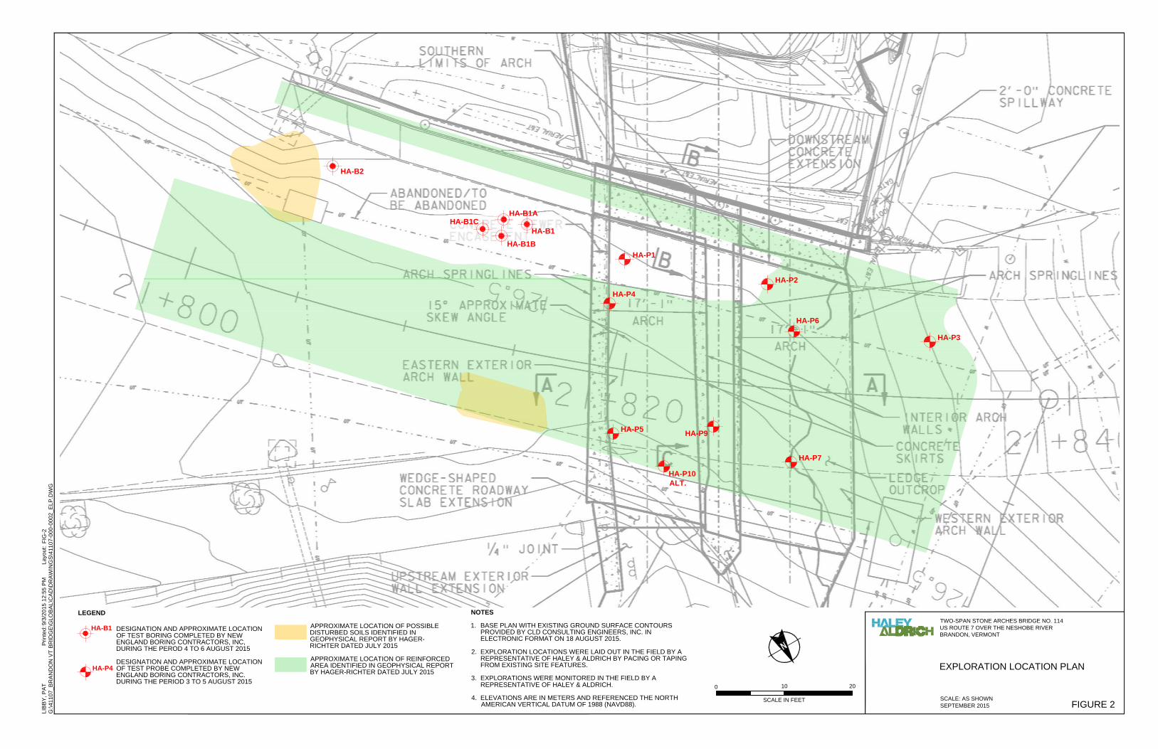
2. Subsurface Explorations and Laboratory Testing 2.1 GEOPHYSICAL SURVEY A geophysical survey using Ground Penetrating Radar (GPR) techniques was conducted at the site on 8 July 2015 by Hager‐Richter Geosciences, Inc. of Salem, New Hampshire. The GPR survey was performed over a 6,000 sq. ft area which extended 20 ft northeast of the bridge to 60 ft southeast of the bridge. A representative of Haley & Aldrich was present to observe the GPR survey work. A lane closure and traffic control was provided by Green Mountain Flagging under contract to Hager‐Richter. A traffic control plan was completed by CLD on 16 June 2015 and utilized for the lane closure. The GPR survey identified 2 areas of possible disturbed soil and reinforced areas of the roadway. These areas identified from the GPR survey are shown on Figure 2. Notably the GPR survey did not find “void space” conditions to a depth of about 4 ft beneath the existing roadway. Results from the survey are included in the report titled “Ground Penetration Radar Survey, US Route 7 Bridge over Neshobe River, Brandon, Vermont” by Hager‐Richter Geosciences, Inc. dated July 2015 which is presented in Appendix A of this report. 2.2 HORIZONTAL CORES Briggs Engineering & Testing of Rockland, Massachusetts collected 4 horizontal cores at the southeast abutment face on 8 July 2015. A representative of Haley & Aldrich was present to observe the locations and collection of the horizontal cores. The cores were collected approximately 2 to 4 ft below the roadway slab elevation along the southeast abutment face. We note that 3 attempts were made approximately 2 ft below the roadway slab but encountered a possible cobble/boulder at a depth of 8 to 9 in. within the core. Due to existing cracking in the core samples, the samples were not suitable for compressive strength testing. A fourth attempt was made approximately 4 ft below the roadway slab where a sample approximately 8 in. long was collected and judged suitable for compressive strength testing. 2.3 TEST BORINGS A drilling program including 5 test borings was completed during the period 4 to 6 August 2015. The test borings were completed by New England Boring Contractors, Inc. of Derry, New Hampshire. Similar to the geophysical survey work, a lane closure and traffic control was provided by Green Mountain Flagging under contract to New England Boring Contractors, Inc. The traffic control plan prepared by CLD was utilized for the lane closure. A representative of Haley & Aldrich was present to document subsurface conditions. The test borings included 4 borings (HA‐B1, HA‐B1A, HA‐B1B, and HA‐B1C) at the area of the existing southeast abutment and 1 boring (HA‐B2) at the area for the proposed future retaining wall. Locations of the test borings are presented on Figure 2.

4
Four attempts were made in the area of boring HA‐B1 to advance the boring to natural materials but due to the presence of cobbles, boulders, granite blocks, or other obstructions the boring could not be advanced beyond 17.8 ft. It is uncertain if the boring encountered natural materials or not. The borings ranged in depth from 4.7 to 17.8 ft below existing grades. 2.4 TEST PROBES A series of roadway probes was completed during the period of 3 to 5 August 2015. The test probes were completed by New England Boring Contractors, Inc. of Derry, New Hampshire. Similar to the geophysical survey work, a lane closure and traffic control was provided by Green Mountain Flagging under contract to New England Boring Contractors, Inc. The traffic control plan by CLD was utilized for the lane closure. A representative of Haley & Aldrich was present to document subsurface conditions. The roadway probes included 10 locations (HA‐P1 through HA‐P10 Alt. excluding HA‐P8 and HA‐P10) within the roadway area. Three probe locations (HA‐P8, HA‐P10, and HA‐P11) were eliminated prior to the start of drilling after conversations with CLD. Locations of the roadway probes are presented on Figure 2. The roadway probes extended through the pavement asphalt, concrete roadway slab (if encountered) and were terminated in the underlying soils, with the exception of HA‐P3 which was performed to identify the asphalt thickness only. The probes ranged in depth from 0.5 to 4 ft below existing grades. 2.5 LABORATORY TESTING 2.5.1 Geotechnical Laboratory Testing Laboratory grain‐size (ASTM D 422) analyses were performed on 8 soil sample recovered from the roadway probes beneath the roadway and/or roadway slab. The geotechnical laboratory testing was completed by GeoTesting Express, Inc. of Acton, Massachusetts. The results of the soil laboratory testing are presented in Appendix B. 2.5.2 Concrete Laboratory Testing Laboratory concrete compressive strength testing was performed on 3 concrete cores collected. Chloride ion tests were performed on 4 concrete cores collected at core depths of 1 in. and 2.5 in. on each core. The concrete laboratory testing was performed by Briggs Engineering & Testing of Rockland, Massachusetts. The results of the concrete laboratory testing are presented in Appendix C.

5
3. Subsurface Conditions The test borings and roadway probes encountered the following generalized soil strata at the site, in order from increasing depth below ground surface. Some strata may be missing at particular locations. We note that the roadway probes were extended just below the roadway/roadway‐slab and terminated in fill soils 0.5 to 4 ft below ground surface, and other soil information below this depth for the area is based on the test borings which were extended to bedrock. A table summarizing the thickness of asphalt, thickness of roadway slab (if encountered), and depth of exploration for the roadway probes is presented in Table I. Asphalt: A thin layer of asphalt, ranging in thickness from 3.5 to 6 in., was encountered at each exploration location at the ground surface. Roadway Slab: The concrete roadway slab was encountered below the asphalt at 7 of the exploration locations. The roadway slab was not observed at locations HA‐P1, HA‐P2, HA‐B1, HA‐B1A, HA‐B1B, HA‐B1C, and HA‐B2. The roadway slab was cored at each location where encountered except HA‐P3. At the locations where slab was cored it ranged from 6 to 7.5 in. thick. Three locations (HA‐P4, HA‐P9, and HA‐P10 Alt.) encountered steel reinforcement at multiple depths along the cores. The steel reinforcement appeared to be about 0.4 in. diameter (close to a No. 3 size rebar). Fill: The fill encountered beneath the asphalt and/or roadway slab from the probes was described as medium dense to dense well graded SAND (SW), poorly graded SAND (SP), poorly graded SAND with silt (SP‐SM), well graded GRAVEL with silt (GW‐GM), poorly graded GRAVEL with silt (GP‐GM), poorly graded GRAVEL (GP), and/or silty SAND (SM) with varying amounts of gravel, sand, and silt. The fill was not fully penetrated at the roadway probe locations. The probes extended to depths ranging from 0.5 to 4 ft below the pavement surface. The fill encountered beneath the asphalt at the boring locations was described as medium dense to dense poorly graded SAND (SP), silty SAND (SM), and/or poorly graded GRAVEL (GP) with varying amounts of sand, gravel, and silt. The fill was most likely fully penetrated at locations HA‐B1B and HA‐B2 where it was found to be 16.7 ft and 8 ft thick, respectively. A large number of obstructions were observed in the fill at locations HA‐B1, HA‐B1A, HA‐B1B, and HA‐B1C. The obstructions were observed from 4 to 12.5 ft below the pavement surface and contained possible boulders, granite blocks, steel plates, etc. that the drilling equipment was not able to advance through. A loss of water return was also noted during the drilling through the fill at these locations. The fill in this area also contained possible brick, ceramic, glass, wood chips, and saw dust at location HA‐B1B. A pocket of ORGANIC SOILS (OL/OH) was encountered from 14 to 17 ft below the pavement surface at location HA‐B1B just above the probable top of bedrock. The fill was not fully penetrated at locations HA‐B1, HA‐B1A, and HA‐B1C due to the presence of obstructions. Forest Mat: A possible old forest mat or topsoil layer was encountered at a depth of 5 ft (El. 409.5) below the ground surface at boring location HA‐B2. The layer was 3.5 ft thick and consisted of very loose to loose dark brown ORGANIC SOILS (OL/OH) and silty SAND (SM) and was directly above the bedrock.

6
Bedrock: Probable bedrock was encountered at 2 test borings (HA‐B1B and HA‐B2) at depths of 17 and 8.5 ft below ground surface (El. 397.7 and 406 respectively). The roller bit was advanced 0.8 to 1.5 ft into the probable bedrock to confirm the bedrock presence. Based on published information for Brandon, Vermont from the United States Geological Survey (USGS), the bedrock is most likely quartzite from the Danby and Potsdam Formation or dolomite from the Gorge Formation. Groundwater was not observed at the roadway probes or boring locations. The Neshobe River level just below the bridge is at about El. 402.6 (normal river level).

7
4. Closure This report has been prepared for specific application to the two‐span stone arches bridge no. 114 over the Neshobe River in Brandon, Vermont, as understood by Haley & Aldrich at this time. In the event that changes in the design or location of the project are planned, the conclusions and recommendations contained in the report should not be considered valid unless they are reviewed and modified or verified in writing by Haley & Aldrich, Inc. Our recommendations are based in part upon data obtained from the referenced subsurface exploration program. The nature and extent of variation between explorations may not become evident until construction. If significant variations then appear, it may be necessary to re‐evaluate the recommendations of this report. G:\41107_Brandon VT Bridge\100\Deliverables\Geotechnical Report\2015‐0909‐HAI‐Bridge No. 114 US Route 7 Over Neshobe River Brandon VT Geotechnical Data Report‐F‐for contract documents.docx

TABLE I SUMMARY OF ROADWAY PROBE EXPLORATIONSTwo‐Span Stone Arches Bridge No. 114
US Route 7 over the Neshobe River
Brandon, Vermont
File No. 41107‐100
Roadway Probe
Exploration No. Approximate Thickness of Asphalt (in.)
Approximate Thickness of Concrete Slab
(in.)Depth of Probe (ft) Notes
HA‐P1 4.5 NE 0.7
HA‐P2 4 NE 0.8
HA‐P3 5.5 see note 2 0.5
HA‐P4 5 6 4.0 reinforcement observed in concrete slab core
HA‐P5 4 6 3.3
HA‐P6 5 6 2.3
HA‐P7 4 6 2.8
HA‐P9 3.5 7.5 1.2 reinforcement observed in concrete slab core
HA‐P10 Alt. 4 7 1.0 reinforcement observed in one of the concrete slab cores
NOTES:
1. Roadway probe exploration locations HA‐P8, HA‐P10, and HA‐P11 were eliminated after discussions on site with CLD.
2. HA‐P3 was included in the program to observe the asphalt thickness (the roadway slab was observed beneath the asphalt but no core sample
or soil samples were obtained).
3. NE designates no concrete slab was encountered beneath the asphalt.
4. A second concrete core was obtained at a location directly adjacent to HA‐P10 Alt. to be submitted for compressive strength laboratory testing.
HALEY & ALDRICH, INC.
G:\41107_Brandon VT Bridge\100\Deliverables\Geotechnical Report\Table I ‐ Summary of Roadway Probe Explorations\2015‐0813‐HAI‐Brandon VT Table I Summary of Roadway Probe Explorations‐D1.xlsx SEPTEMBER 2015

APPROXIMATE SCALE: 1 IN = 2000 FTSEPTEMBER 2015 FIGURE 1
PROJECT LOCUS
TWO-SPAN STONE ARCHES BRIDGE NO. 114 US ROUTE 7 OVER THE NESHOBE RIVER BRANDON, VERMONT
4110
7-10
0_1_
LOC
US.
SITE COORDINATES: 43°47'58"N, 73°5'20"WMAP SOURCE: ESRI
HA-B2
HA-B1C
HA-B1A
HA-B1
HA-B1B
HA-P1
HA-P5
HA-P10
ALT.
HA-P9
HA-P4
HA-P7
HA-P2
HA-P3
HA-P6
LEGEND
DESIGNATION AND APPROXIMATE LOCATION
OF TEST BORING COMPLETED BY NEW
ENGLAND BORING CONTRACTORS, INC,
DURING THE PEROD 4 TO 6 AUGUST 2015
DESIGNATION AND APPROXIMATE LOCATION
OF TEST PROBE COMPLETED BY NEW
ENGLAND BORING CONTRACTORS, INC.
DURING THE PERIOD 3 TO 5 AUGUST 2015
NOTES
1. BASE PLAN WITH EXISTING GROUND SURFACE CONTOURS
PROVIDED BY CLD CONSULTING ENGINEERS, INC. IN
ELECTRONIC FORMAT ON 18 AUGUST 2015.
2. EXPLORATION LOCATIONS WERE LAID OUT IN THE FIELD BY A
REPRESENTATIVE OF HALEY & ALDRICH BY PACING OR TAPING
FROM EXISTING SITE FEATURES.
3. EXPLORATIONS WERE MONITORED IN THE FIELD BY A
REPRESENTATIVE OF HALEY & ALDRICH.
4. ELEVATIONS ARE IN METERS AND REFERENCED THE NORTH
AMERICAN VERTICAL DATUM OF 1988 (NAVD88).
G:\41107_B
RA
ND
ON
V
T B
RID
GE
\G
LO
BA
L\C
AD
\D
RA
WIN
GS
\41107-000-0002_E
LP
.D
WG
LIB
BY
, P
AT
FIG
-2
9/3/2015 12:55 P
MLayout:
Printed:
FIGURE 2
TWO-SPAN STONE ARCHES BRIDGE NO. 114
US ROUTE 7 OVER THE NESHOBE RIVER
BRANDON, VERMONT
EXPLORATION LOCATION PLAN
SCALE: AS SHOWN
SEPTEMBER 2015
0
10 20
SCALE IN FEET
HA-B1
HA-P4
APPROXIMATE LOCATION OF POSSIBLE
DISTURBED SOILS IDENTIFIED IN
GEOPHYSICAL REPORT BY HAGER-
RICHTER DATED JULY 2015
APPROXIMATE LOCATION OF REINFORCED
AREA IDENTIFIED IN GEOPHYSICAL REPORT
BY HAGER-RICHTER DATED JULY 2015

APPENDIX A
Geophysical Report by Hager‐Richter

HAGER-RICHTERGEOSCIENCE, INC.
GROUND PENETRATING RADAR SURVEYUS ROUTE 7 BRIDGE OVER NESHOBE RIVER
BRANDON, VERMONT
H&A File No 41107-970
Prepared for:
Haley & Aldrich, Inc.3 Bedford Farms Drive Bedford, New Hampshire 03110
Prepared by:
Hager-Richter Geoscience, Inc.8 Industrial Way - D10Salem, New Hampshire 03079
File 15SG11July, 2015
© 2015 Hager-Richter Geoscience, Inc.

HAGER-RICHTERGEOSCIENCE, INC.
CONSULTANTS IN GEOLOGY AND GEOPHYSICS
8 INDUSTRIAL WAY - D10
SALEM, NEW HAMPSHIRE 03079-5820
TELEPHONE (603) 893-9944
FAX (603) 893-8313
SALEM, NEW HAMPSHIRE • FORDS, NEW JERSEY
www.hager-richter.com
July 23, 2015File 15SG11
Meghan M. Hatton Senior Engineer T: (603) 391.3326 Haley & Aldrich, Inc. C: (857) 383.86033 Bedford Farms Drive Email: [email protected], New Hampshire 03110
RE: Ground Penetrating Radar SurveyUS Route 7 Bridge over Neshobe RiverBrandon, VermontH&A File No 41107-970
Dear Ms. Hatton:
In this letter we report the results of a ground penetrating radar (GPR) survey conductedby Hager-Richter Geoscience, Inc. (Hager-Richter) at the above referenced Site as part of ageotechnical investigation of the bridge by Haley & Aldrich, Inc. (H&A) in July, 2015. Thescope of the project and area of interest were specified by H&A.
INTRODUCTION
The Site is an active bridge on US Route 7 over the Neshobe River in Brandon, Vermont. The general location of the Site is shown in Figure 1. The bridge is a twin bore stone-archbridge. According to information provided by H&A, the bridge has been adversely impacted byflooding, and settlement has occurred along the approaches for the bridge. H&A was interestedin determining whether voids are present below the approaches and bridge deck.
H&A specified an area of interest (AOI) measuring about 50 feet wide by 120 feet longthat extends from about 20 feet northwest of the bridge to about 60 feet southeast of the bridge. Figure 2 is a Site Plan showing the area of interest for the geophysical survey. The bridgesurface in the AOI was asphalt paved. A few subtle surface depressions were visible in thepavement surface at the time of the survey and were water filled due to recent rainfall. Thegeophysical survey was conducted during daytime hours and included lane closures to minimizeimpacts to traffic.
OBJECTIVE
The objective of the geophysical survey was to detect possible voids below the roadway

HAGER-RICHTERGEOSCIENCE, INC.Ground Penetrating Radar Survey
US Route 7 Bridge over Neshobe RiverBrandon, VermontH&A File No 41107-970File 15SG11 Page 2
in the accessible portions of the specified area of interest at the site.
THE SURVEY
Michael Howley, P.G., and Michael Lavery of Hager-Richter conducted the field work onJuly 8, 2015. The project was coordinated with Meghan M. Hatton, P.E., of H&A. Ms. Hattonwas present for the duration of the field work and specified the area of interest. Traffic controlservices were provided by Green Mountain Flagging, LLC.
The GPR survey was conducted across the accessible portions of the specified AOI. GPRdata were acquired along parallel traverses spaced 1 foot apart oriented parallel to the travellanes, and along parallel traverses spaced 10 feet apart oriented perpendicular to the travel lanes,as access permitted. Such tightly spaced GPR traverses are sufficient to detect voids withminimum dimensions of 1-2 feet in lateral size.
The GPR signature for voids is site specific and non-unique. Other structures orsubsurface conditions may produce GPR reflections that are similar to the GPR reflectionscaused by voids. Whether voids are actually present can only be determined by ground truth suchas through borings and/or test excavations.
EQUIPMENT AND PROCEDURES
The GPR survey was conducted using our GSSI UtilityScan DF subsurface imagingradar system. The system includes a survey wheels that trigger the recording of the data at fixedintervals, thereby increasing the accuracy of the locations of features detected along the surveylines. The GPR data were acquired simultaneously using 300 MHz and 800 MHztransmit/receive antennas.
GPR uses a high-frequency electromagnetic pulse (referred to herein as “radar signal”)transmitted from a radar antenna to probe the subsurface. The transmitted radar signals arereflected from subsurface interfaces of materials with contrasting electrical properties. Traveltimes of the radar signal can be converted to approximate depth below the surface by correlationwith targets of known depths. We monitor the acquisition of GPR data in the field and record theGPR data digitally for subsequent processing. Interpretation of the records is based on the natureand intensity of the reflected signals and on the resulting patterns.
Data from the GPR survey were processed using RADAN 7, commercially licensed GPRprocessing software from GSSI. The GPR data were examined in both profile format and ashorizontal depth slices.

HAGER-RICHTERGEOSCIENCE, INC.
Ground Penetrating Radar SurveyUS Route 7 Bridge over Neshobe RiverBrandon, VermontH&A File No 41107-970File 15SG11 Page 3
LIMITATIONS OF THE METHOD
HAGER-RICHTER GEOSCIENCE, INC. MAKES NO GUARANTEE THAT ALL VOIDS, AREAS OF SOFT MATERIALS, OR OTHER TARGETS OF INTERESTWERE DETECTED IN THIS SURVEY. HAGER-RICHTER GEOSCIENCE, INC.IS NOT RESPONSIBLE FOR DETECTING TARGETS THAT CANNOT BEDETECTED DUE TO SITE CONDITIONS OR DUE TO THE LIMITATIONS OFTHE GPR METHOD.
GPR detects and maps interfaces of contrasting electrical properties, and an air-filled voidhas electrical properties very different from soil and rock. The GPR method is useful fordetecting voids and determining their footprint, but in general, GPR data cannot be used todetermine the thickness of voids.
There are other limitations of the GPR technique: (1) surface conditions, (2) electricalconductivity and thickness of the subsurface layers, (3) electrical properties of the target(s), and(4) spacing of the traverses. Of these restrictions, only the last is controllable by us in mostcases.
The condition of the survey surface can affect the quality of the GPR data and the depthof penetration of the GPR signal. For exterior sites, a surface covered with obstacles such asautomobiles, dumpsters, thick leaf debris, materials piles, etc. limit the survey access. Similarly,for interior sites, a surface covered with obstacles such as desks, benches, laboratory equipment,etc. also limit access. Some floor coverings may limit the coupling of the GPR antenna with thesubsurface.
The electrical conductivity of the subsurface determines the attenuation of the GPRsignals, and thereby limits the maximum depth of exploration. The GPR signal does notpenetrate clay-rich soils or soils contaminated with road salt. In some cases, the GPR signal maynot penetrate below concrete pavement, and some asphalts are electrically conducting.
A strong contrast in the electrical conductivities of the ground and the target (forexamples, UST, pipe, void, dry well, drum, contaminant plume) is required to obtain a reflectionof the GPR signal. If the contrast is too small, then the reflection may be too weak to recognize,and the target can be missed.
Spacing of the traverses is limited by access at many sites, but where flexibility oftraverse spacing is possible, the spacing is adjusted on the basis of the size of the target.

HAGER-RICHTERGEOSCIENCE, INC.
Ground Penetrating Radar SurveyUS Route 7 Bridge over Neshobe RiverBrandon, VermontH&A File No 41107-970File 15SG11 Page 4
RESULTS
The GPR survey was conducted along traverses spaced one foot apart along the long axisof the bridge and at 10-foot intervals along the short axis of the bridge. Figure 3 shows thelocations of the GPR traverses and our interpretation of the data. Prior experience hasdemonstrated that GPR reflections from voids are site-specific and non-unique. Where possible,the GPR signal response at the locations of known voids is used to characterize reflectionpatterns at a particular site. At the subject site, however, known voids or surface depressionswere not available.
GPR signal penetration for the different frequency antennae was very similar. The GPRdata acquired with the 800 MHz antenna were used for interpretation due to higher resolution ofthe GPR records. Apparent GPR signal penetration at the Site was fair, with reflections receivedfor approximately 20-30 ns of the 45 ns time window. Although GPR measures the timebetween sending and receiving EM energy, most applications of the GPR method require thedepth of the reflecting objects, not the time. Thus, the velocities of propagation of EM energy insubsurface materials are required to convert time, the parameter measured, to depth, theparameter desired. Three methods are commonly used to determine velocity of the GPR signal insitu in the absence of coring: (1) fitting a hyperbola to reflections due to small objects, (2) thecommon mid-point method of interpretation, and (3) direct transmission through the subsurface. GPR software such as RADAN 7 has the capabilities to perform hyperbola matching, that allowsdetermination of the velocity in situ. Using the estimated velocity for the propagation of theGPR signal yields to an average GPR signal penetration of approximately 3-4 feet.
GPR reflections typical of disturbed soils are evident in the records for two locations inthe specified area of interest. Both areas are located in the approach on the southeast side of thebridge and are located in the vicinity of catch basins. Whether the disturbed soils are due to thecatch basins or related storm drain lines cannot be determined on the basis of the GPR data. Figure 4 is an example of a GPR record that crosses the northern area of disturbed soils. According to information provided by H&A, the southern area of disturbed soils might belocated in an area where a void was repaired in the past.
The GPR records exhibit reflections typical of reinforcement steel in the central portionof the bridge and much of the northwestern approach to the bridge. The area where reinforcingsteel is inferred to be present is shown as a stippled area on Figure 3. GPR reflections typical ofreinforcement are shown in the example GPR record in Figure 4. The rows of reinforcing arespaced approximately 2.5 feet apart and are oriented both parallel and perpendicular to the longaxis of the bridge. GPR reflections typical of reinforcing steel are not present in the data for theareas not stippled in Figure 3.
HAGER-RICHTERGEOSCIENCE, INC.
Ground Penetrating Radar SurveyUS Route 7 Bridge over Neshobe RiverBrandon, VermontH&A File No 41107-970File 15SG11 Page 5
CONCLUSIONS
Based on the geophysical survey performed by Hager-Richter for H&A at the US Route 7Bridge over Neshobe River in Brandon, Vermont in July, 2015, we conclude:
• Two areas of disturbed soils were detected in the vicinity of catch basins in the southeastapproach to the bridge.
• Reinforcement steel is present through much of the bridge deck and northwesternapproach to the bridge and is spaced at approximately 2.5-foot intervals.
LIMITATIONS
This letter report was prepared for the exclusive use of Haley & Aldrich, Inc. (Client). No other party shall be entitled to rely on this Report or any information, documents, records,data, interpretations, advice or opinions given to Client by Hager-Richter Geoscience, Inc. (H-R)in the performance of its work. The Report relates solely to the specific project for which H-Rhas been retained and shall not be used or relied upon by Client or any third party for anyvariation or extension of this project, any other project or any other purpose without the expresswritten permission of H-R. Any unpermitted use by Client or any third party shall be at Client'sor such third party's own risk and without any liability to H-R.
H-R has used reasonable care, skill, competence and judgment in the performance of' itsservices for this project consistent with professional standards for those providing similarservices at the same time, in the same locale, and under like circumstances. Unless otherwisestated, the work performed by H-R should be understood to be exploratory and interpretational incharacter and any results, findings or recommendations contained in this Report or resulting fromthe work proposed may include decisions which are judgmental in nature and not necessarilybased solely on pure science or engineering. It should be noted that our conclusions might bemodified if subsurface conditions were better delineated with additional subsurface explorationincluding, but not limited to, test pits, soil borings with collection of soil and water samples, andlaboratory testing.
Except as expressly provided in this limitations section, H-R makes no other repre-sentation or warranty of any kind whatsoever, oral or written, expressed or implied; and allimplied warranties of merchantability and fitness for a particular purpose, are hereby disclaimed.

HAGER-RICHTERGEOSCIENCE, INC.
Ground Penetrating Radar SurveyUS Route 7 Bridge over Neshobe RiverBrandon, VermontH&A File No 41107-970File 15SG11 Page 6
If you have any questions or comments on this letter report, please contact us at yourconvenience. It has been a pleasure to work with H&A on this project. We look forward toworking with you again in the future.
Sincerely yours,HAGER-RICHTER GEOSCIENCE, INC.
Jeffrey Reid, P.G. Dorothy Richter, P.G.Vice President/Senior Geophysicist President
Attachments: Figures 1-4


APPENDIX B
Geotechnical Laboratory Test Results


APPENDIX C
Concrete Laboratory Test Results