On-FPGA Communication Architectures. 2 On-FPGA Communications Must provide high bandwidth and...
53
On-FPGA Communication Architectures
-
Upload
randell-greene -
Category
Documents
-
view
224 -
download
0
Transcript of On-FPGA Communication Architectures. 2 On-FPGA Communications Must provide high bandwidth and...
On-FPGA Communication Architectures
2
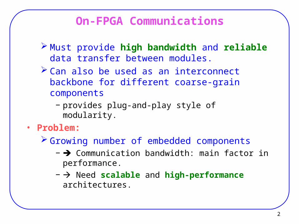
On-FPGA Communications
Must provide high bandwidth and reliable data transfer between modules.
Can also be used as an interconnect backbone for different coarse-grain components
− provides plug-and-play style of modularity.
• Problem: Growing number of embedded components
− Communication bandwidth: main factor in performance.
− Need scalable and high-performance architectures.
3
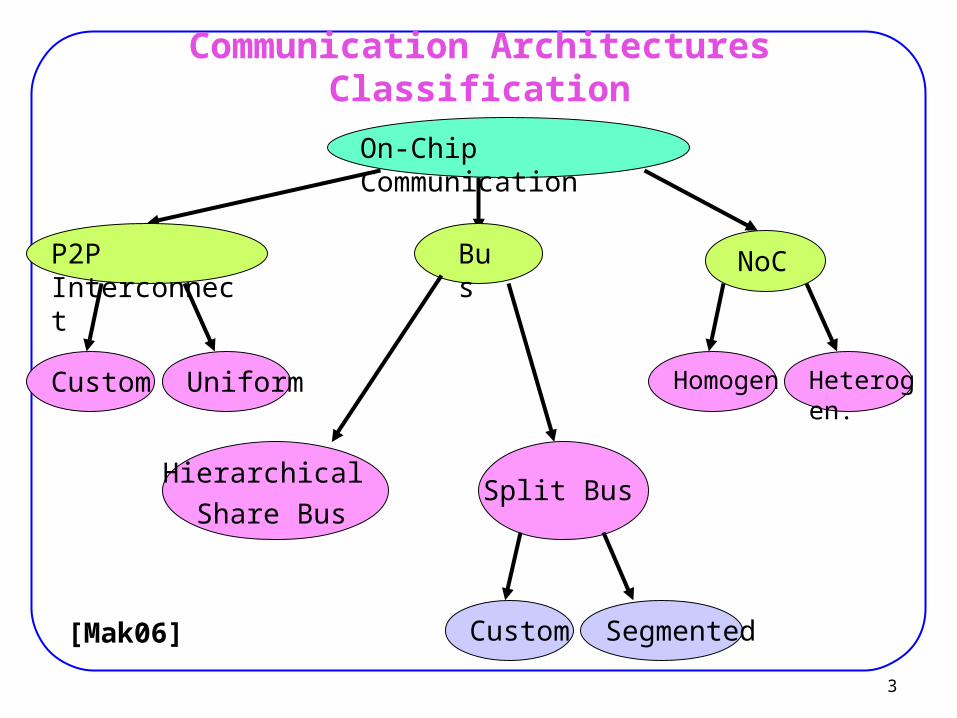
Communication Architectures Classification
On-Chip Communication
P2P Interconnect Bus NoC
Custom Uniform
Hierarchical
Share BusSplit Bus
Homogen Heterogen.
Custom Segmented[Mak06]
4
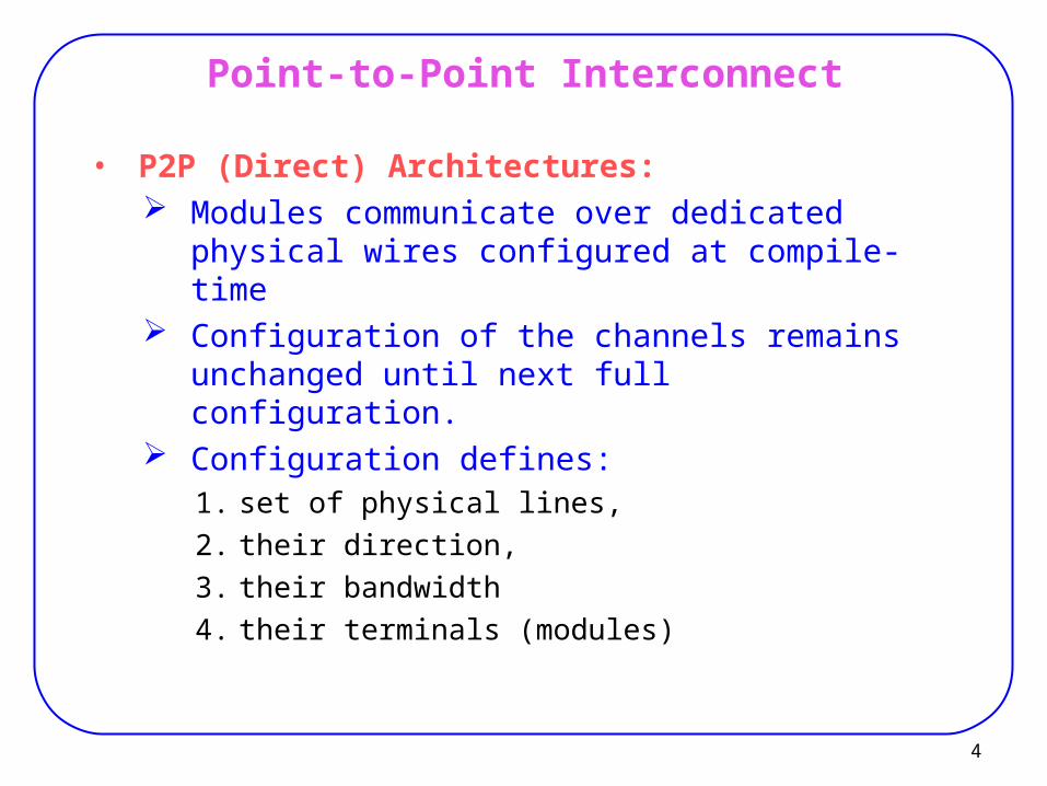
Point-to-Point Interconnect
• P2P (Direct) Architectures: Modules communicate over dedicated physical wires
configured at compile-time Configuration of the channels remains unchanged
until next full configuration. Configuration defines:
1. set of physical lines,
2. their direction,
3. their bandwidth
4. their terminals (modules)
5
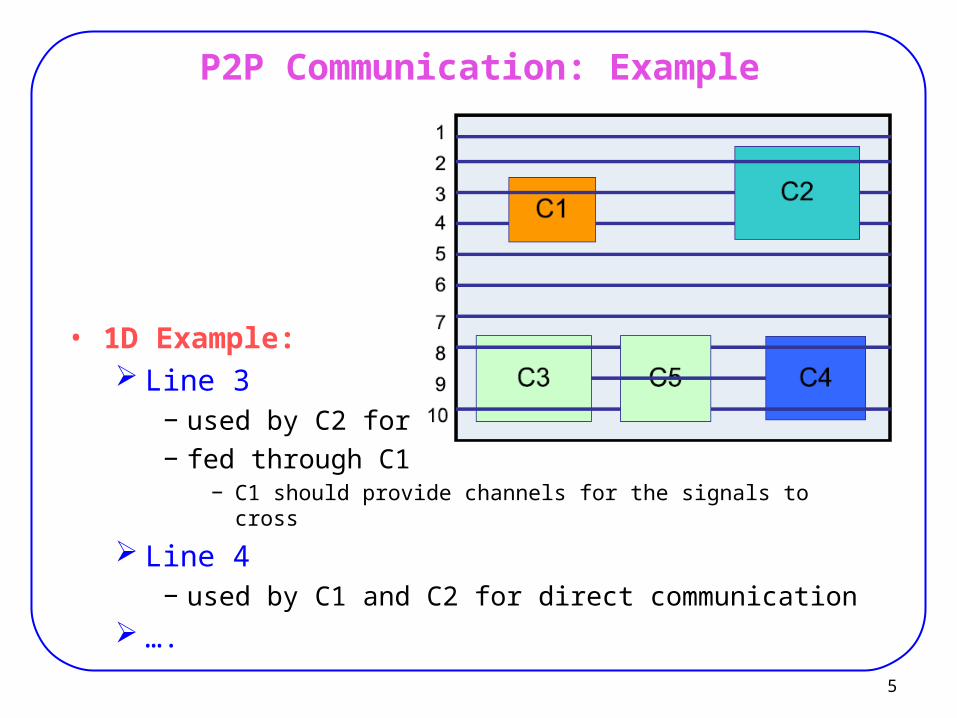
P2P Communication: Example
• 1D Example: Line 3
− used by C2 for I/O− fed through C1
− C1 should provide channels for the signals to cross
Line 4− used by C1 and C2 for direct communication
….
6
Point-to-Point Interconnect
• Advantages: Simple
− Widely used Deterministic latency and performance
− Reason: Channels are not shared
• Disadvantage: Puts restriction on the design of components.
− Dedicated channels must be foreseen to allow signals to cross. Placer must deal with restrictions as availability of wires.
− Possible for offline placement (at compile time). Not scalable:
− As # channels grows, the number of wires required increases rapidly.− Routing becomes very difficult.
Low wire utilization for low bandwidth channels. High hardware overhead.
7
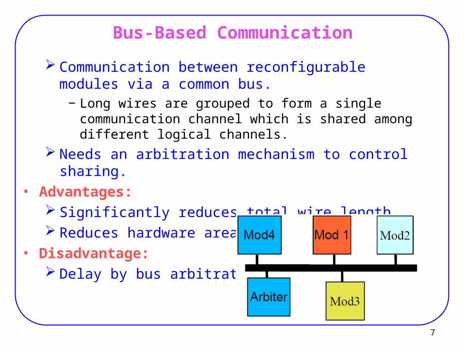
Bus-Based Communication
Communication between reconfigurable modules via a common bus.
− Long wires are grouped to form a single communication channel which is shared among different logical channels.
Needs an arbitration mechanism to control sharing.
• Advantages: Significantly reduces total wire length. Reduces hardware area for interfaces.
• Disadvantage: Delay by bus arbitration.
8
Bus-Based Communication
• Xilinx: uses CoreConnect bus architecture (from IBM)
− for both hard-core and soft-core processors− Virtex-II Pro and Virtex 4.
9
Circuit Switching
• Circuit Switching: Dynamically establishes a connection between two PEs. Uses a set of physical lines connected by switches. PEs arranged in a mesh. Switches available at column/rowintersections to allow a
longer connection− Two PEs can be connected at run-time setting the switches
on the path
Once the connection is established, data can be transferred in one clock.
• Example: Connection mechanism in most FPGAs (fine grained idea). PACT-XPP
10
Circuit Switching
• Advantage (application): In fine-grained image computing systems:
− Dynamically changes the topology of a parallel computer to accommodate the best structure of the application .
• Disadvantages: Long Delay:
− When the connection must go through many processors.− (must pass through many switches).
Dynamic computation of routes:− Needs run-time routing (when placement is changed
dynamically)− Very time consuming Long overall computation time.
Exclusive use of chip space:− Next page
11
Circuit Switching
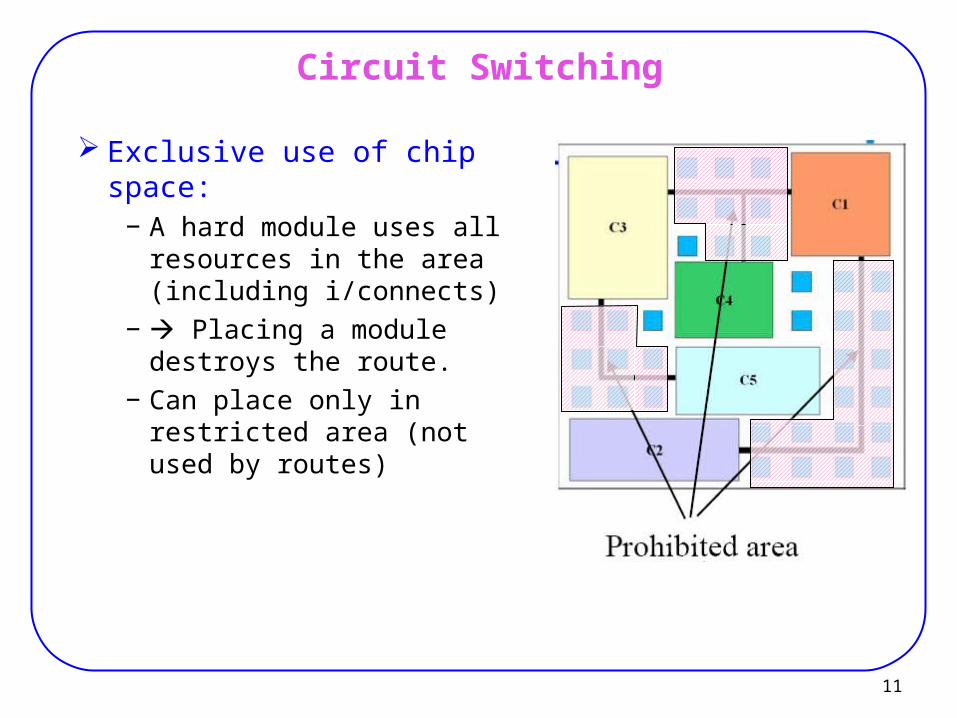
Exclusive use of chip space:− A hard module uses all
resources in the area (including i/connects)
− Placing a module destroys the route.
− Can place only in restricted area (not used by routes)
12
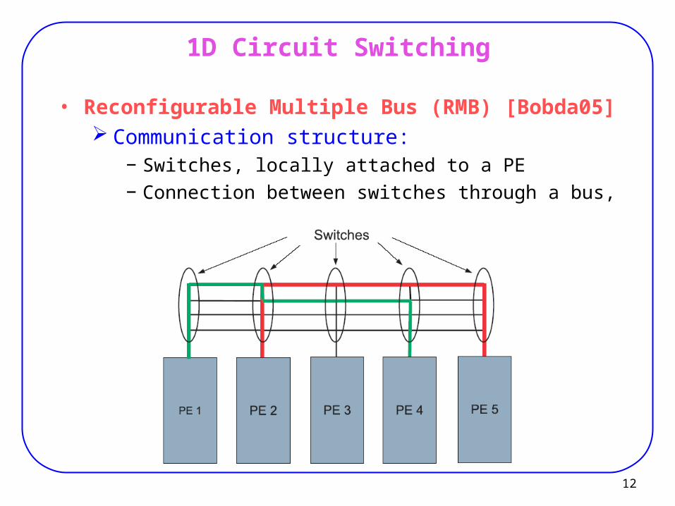
1D Circuit Switching
• Reconfigurable Multiple Bus (RMB) [Bobda05] Communication structure:
− Switches, locally attached to a PE− Connection between switches through a bus,
13
1D Circuit Switching
• Procedure (connection from Pk to Pt):
Pk sends request to its own switch sk.
sk sends the request to sk+1
.... st
Each switch checks if there is available channel on the switch
If yes, the switch sets a connection and sends and ack.− from st to … sk
If not, reject or queue the request When the sender receives ack, it starts communcation.
14
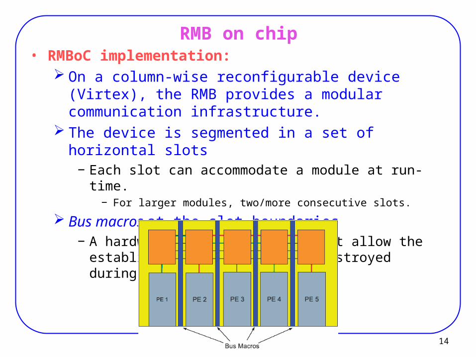
RMB on chip• RMBoC implementation:
On a column-wise reconfigurable device (Virtex), the RMB provides a modular communication infrastructure.
The device is segmented in a set of horizontal slots− Each slot can accommodate a module at run-time.
− For larger modules, two/more consecutive slots.
Bus macros at the slot boundaries− A hardware module which does not allow the established
connection to be destroyed during the reconfiguration.
15
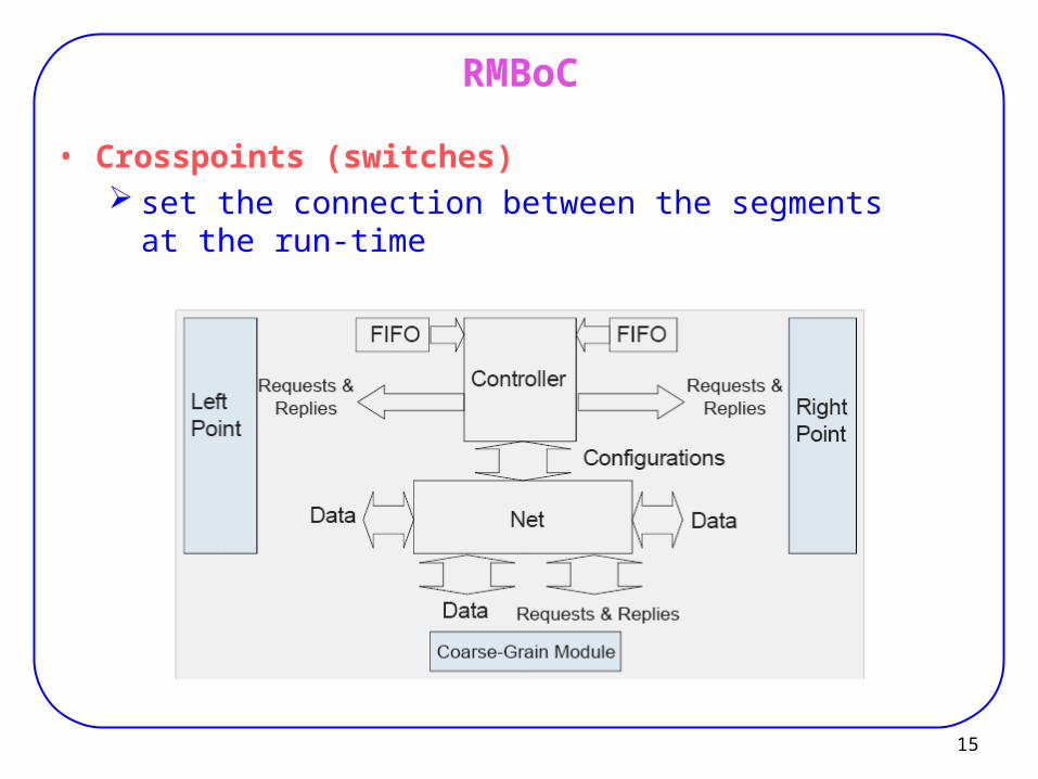
RMBoC
• Crosspoints (switches) set the connection between the segments at the run-
time
16
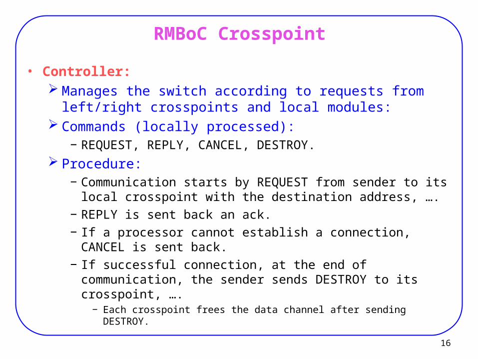
RMBoC Crosspoint
• Controller: Manages the switch according to requests from left/right
crosspoints and local modules: Commands (locally processed):
− REQUEST, REPLY, CANCEL, DESTROY. Procedure:
− Communication starts by REQUEST from sender to its local crosspoint with the destination address, ….
− REPLY is sent back an ack.− If a processor cannot establish a connection, CANCEL is
sent back.− If successful connection, at the end of communication, the
sender sends DESTROY to its crosspoint, ….− Each crosspoint frees the data channel after sending DESTROY.
17
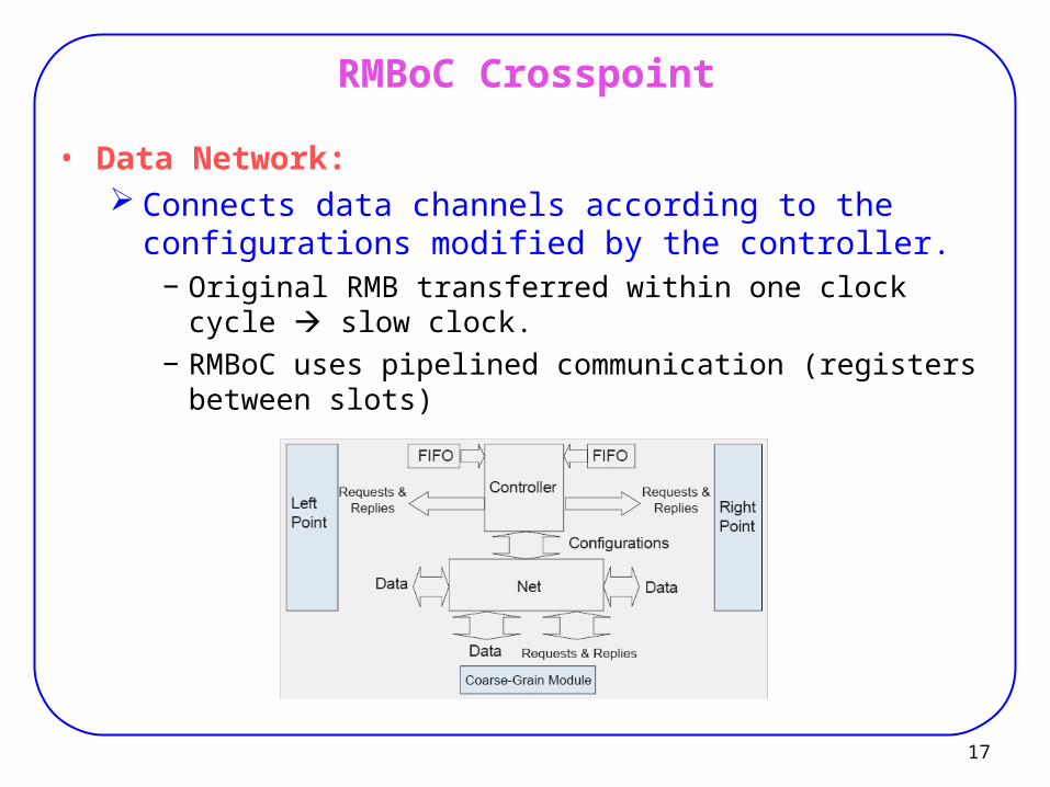
RMBoC Crosspoint
• Data Network: Connects data channels according to the configurations
modified by the controller.− Original RMB transferred within one clock cycle slow
clock.− RMBoC uses pipelined communication (registers between
slots)
18
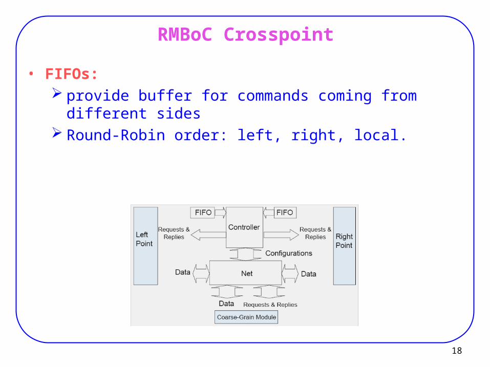
RMBoC Crosspoint
• FIFOs: provide buffer for commands coming from different sides Round-Robin order: left, right, local.
Network on Chip
20
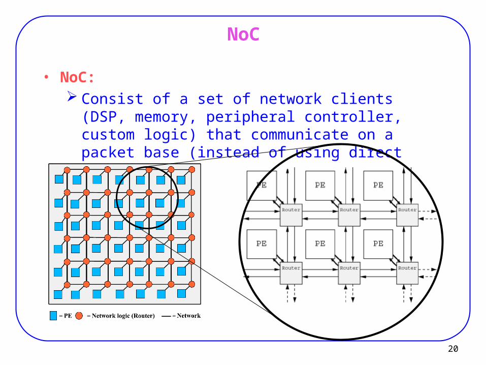
NoC
• NoC: Consist of a set of network clients (DSP, memory,
peripheral controller, custom logic) that communicate on a packet base (instead of using direct connection).
21
NoC
modules (network client) placed at fixed locations on the chip can exchange packets in the common network.
• Advantage: Very high flexibility
− because no route has to be computed before allowing components to start communicating.
Components just send packets, and they do not care on how the packets are routed in the network.
• Example: QuickSilver (FPL 2004)
22
NoC Characteristics
• An NoC architecture is characterized by:
1. number of routers, each attached to PE in the array,
2. bandwidth of the communication channels between the routers,
3. topology of the network
4. the mechanism used for packet forwarding.
• Major components: Router PE
23
NoC vs. Macro Network
• Noc must have little area overhead. especially for fine grain architectures (e.g. FPGA). Few registers are used as buffers for on-chip routers.
24
Network Topologies
• 2-D Mesh
• Torus
25
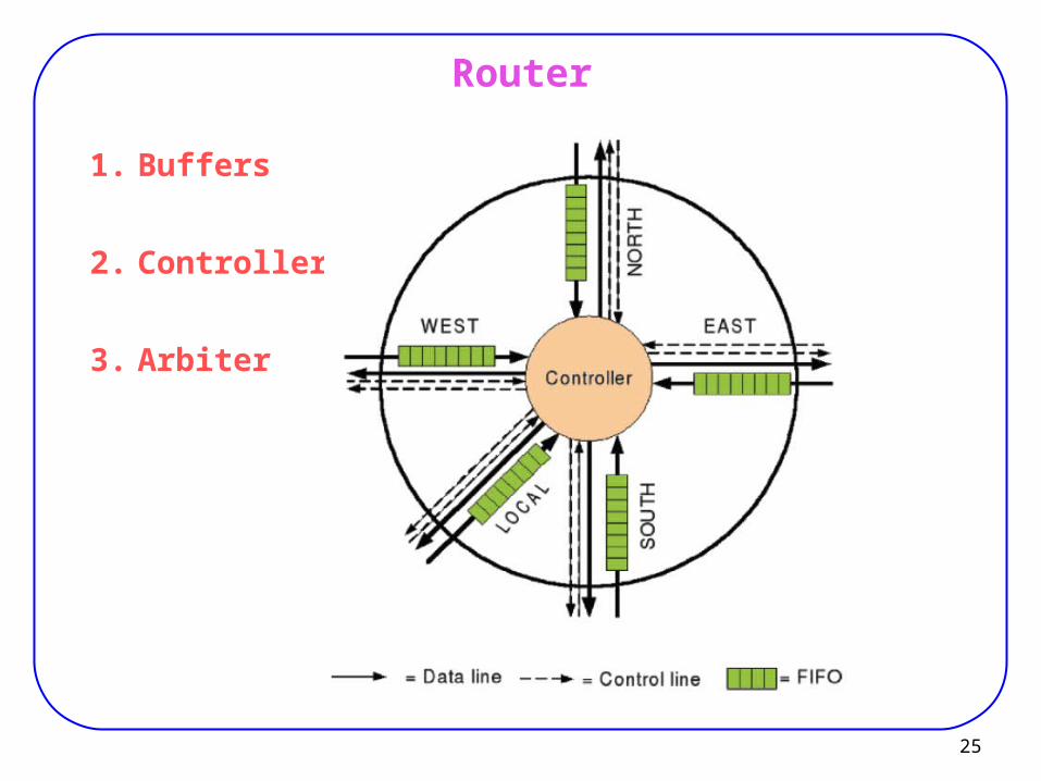
Router
1. Buffers
2. Controller
3. Arbiter
26
Router Components
1. Buffers: Usually implemented as FIFO. Temporally store messages coming from five
directions. Each router (willing to send a message in a given
direction) copies it into the FIFO of the neighbor router in that direction.
Then data are placed on the data lines and the control signals are used to handshake between neighbor routers.
27
Router Components
2. Controller: determines how to forward the packet,
− usually according to the destination address.
3. Output arbiters: For four directions and PE. manage the assignment of the message to output
channels.
28
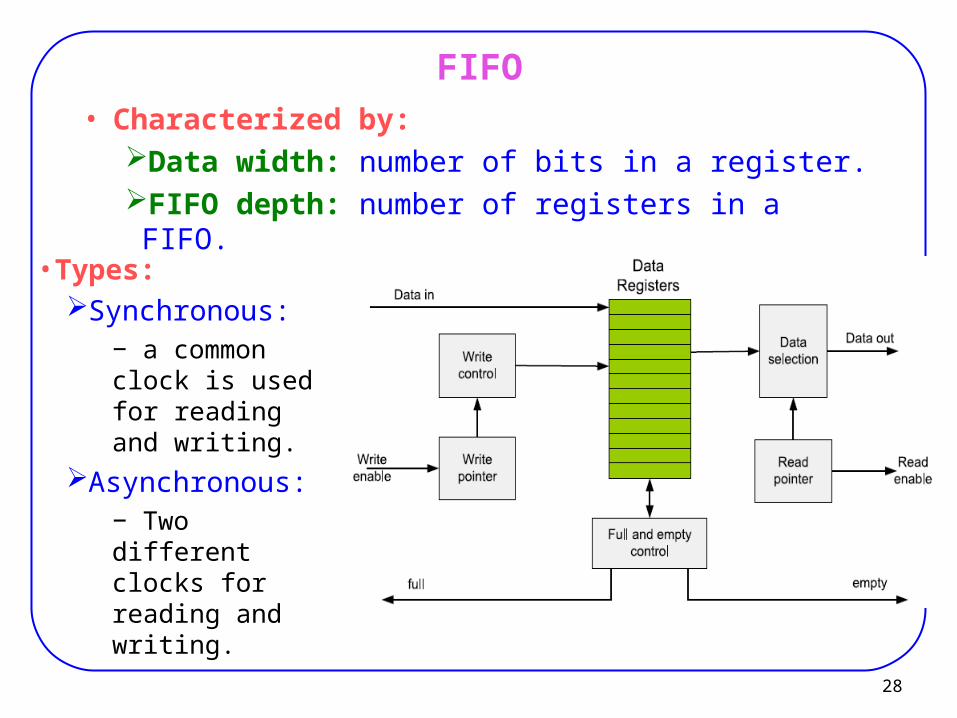
FIFO• Characterized by:
Data width: number of bits in a register.FIFO depth: number of registers in a FIFO.
• Types:Synchronous:
− a common clock is used for reading and writing.
Asynchronous:− Two different clocks for reading and writing.
29
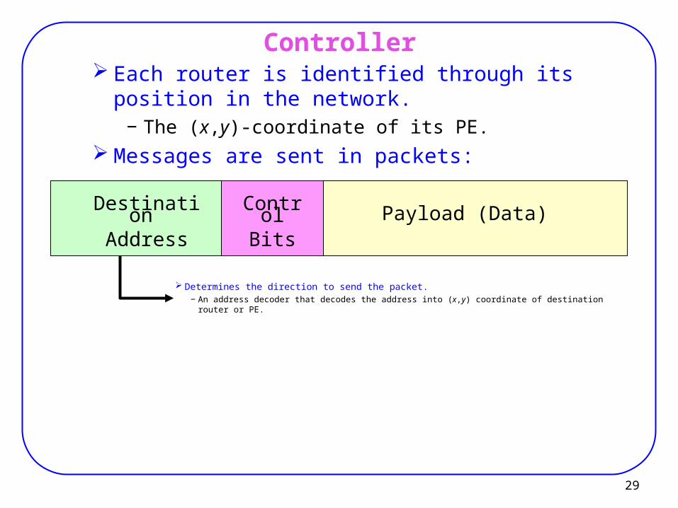
Controller Each router is identified through its position in the
network.− The (x,y)-coordinate of its PE.
Messages are sent in packets:
Destination Address
ControlBits
Payload (Data)
Determines the direction to send the packet.− An address decoder that decodes the address into (x,y) coordinate of destination router or PE.
30
Controller
Destination Address
ControlBits
Payload (Data)
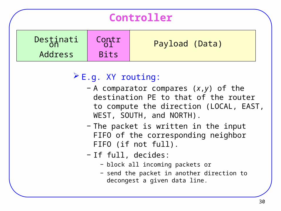
E.g. XY routing:− A comparator compares (x,y) of the destination
PE to that of the router to compute the direction (LOCAL, EAST, WEST, SOUTH, and NORTH).
− The packet is written in the input FIFO of the corresponding neighbor FIFO (if not full).
− If full, decides:− block all incoming packets or − send the packet in another direction to decongest a given
data line.
31
Output Arbiter
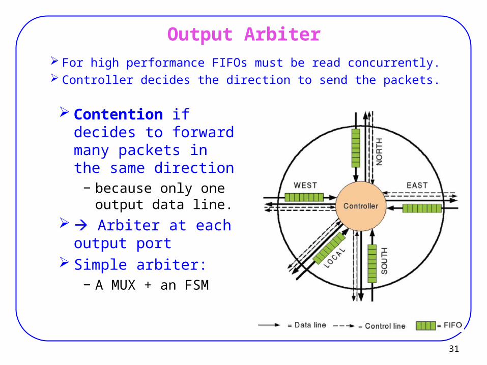
For high performance FIFOs must be read concurrently. Controller decides the direction to send the packets.
Contention if decides to forward many packets in the same direction
− because only one output data line.
Arbiter at each output port
Simple arbiter:− A MUX + an FSM
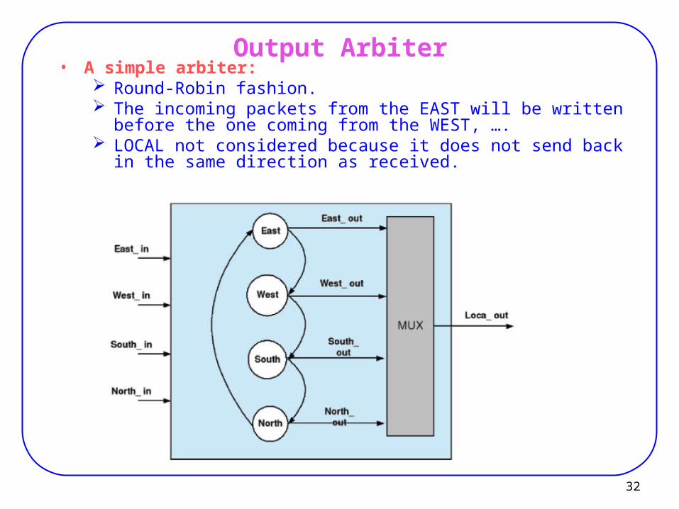
32
Output Arbiter• A simple arbiter:
Round-Robin fashion. The incoming packets from the EAST will be written before the one
coming from the WEST, …. LOCAL not considered because it does not send back in the same
direction as received.
33
Processing Element
• PE can be: processor core, memory block, embedded programmable logic, custom hardware block, ….
• PE is connected to network through wrapper.
• Wrapper: controls all the transactions on the network and provides a simple interface for PE to access the
network.
34
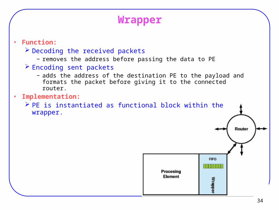
Wrapper
• Function: Decoding the received packets
− removes the address before passing the data to PE Encoding sent packets
− adds the address of the destination PE to the payload and formats the packet before giving it to the connected router.
• Implementation: PE is instantiated as functional block within the wrapper.
35
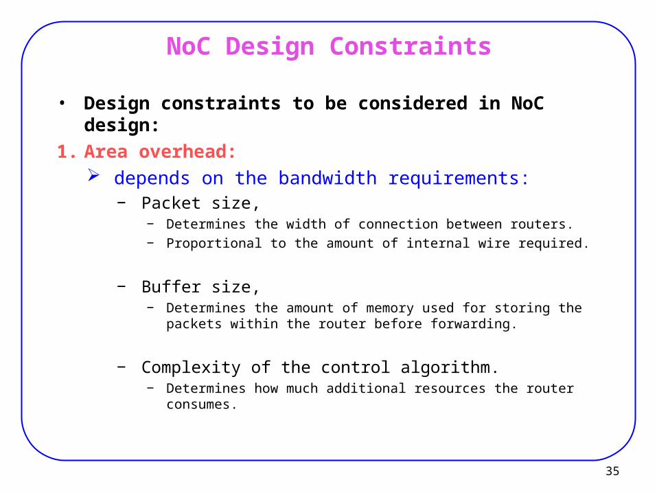
NoC Design Constraints
• Design constraints to be considered in NoC design:
1. Area overhead: depends on the bandwidth requirements:
− Packet size,− Determines the width of connection between routers.− Proportional to the amount of internal wire required.
− Buffer size,− Determines the amount of memory used for storing the packets
within the router before forwarding.
− Complexity of the control algorithm.− Determines how much additional resources the router consumes.
36
NoC Design Constraints
2. Latency:
• the time a message needs from its source to its destination.
• Components: the time needed to setup a route
− In circuit switching: request and acknowledgment latency,
− in packet routing: no such set up time.
+ the time needed to transfer the payload to destination.
37
Latency
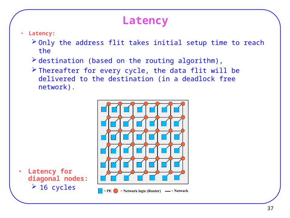
• Latency for diagonal nodes: 16 cycles
• Latency:
Only the address flit takes initial setup time to reach the destination (based on the routing algorithm), Thereafter for every cycle, the data flit will be delivered to
the destination (in a deadlock free network).
38
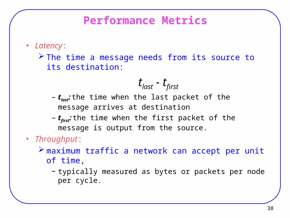
Performance Metrics
• Latency: The time a message needs from its source to its
destination:
tlast - tfirst
− tlast: the time when the last packet of the message arrives at destination
− tfirst: the time when the first packet of the message is output from the source.
• Throughput: maximum traffic a network can accept per unit of time,
− typically measured as bytes or packets per node per cycle.
Routing Techniques
40
Routing Techniques
• Routing Algorithms: Circuit Switching Store-and-Forward Virtual Cut-Through Wormhole Routing ….
41
Circuit Switching
• A communication path is created from the source to the destination before transmitting any data.1. A routing probe traverses network and reserving links to
transmit the data. − Probe contains the source and destination addresses.
2. Once the routing probe reaches the destination address, an acknowledgment is sent back to the source address,
3. The data are transferred at the full bandwidth of the hardware.
4. The circuit remains operational until the end of data to be transmitted.
5. The lock on the links may be released once all the data have reached the destination by sending back another acknowledgment through the same route to the source.
42
Circuit Switching
• Disadvantage: long time to establish a dedicated link
• Useful when tsu << tmsg
i.e. when long messages are present.
43
Store-and-Forward (SAF)
• At each node:1. the packets are stored in memory.2. the routing information is examined to determine
which output channel to direct the packet.3. the packet is sent to the neighbor.
• Latency:
Nr * tr
Nr: number of routers through which the packet must travel
tr: time to transfer the packet between the routers
44
Virtual Cut-Through (VCT)
As the routing information is carried in the header, the packet should not be stored in the current node’s memory if an output buffer is available.
− The packet simply cuts through the router of the node to an available output channel.
• Advantage: Less amount of memory along the path.
− But enough memory has to be allocated if an output channel is not available.
− At high volumes of messages on the network:
VCT ≈ SAF
45
Wormhole Routing
Addresses the deficiency in VCT:− If an output channel is not available, the packet must be
stored in the current node’s memory.
Divides a message into flits:− smaller flow-control digits than packets,
Each message contains one header flit and many data flits.− header: carries the routing and control information
• Procedure:
1. If an output channel is available, the header flit is routed
2. Remaining data flits follow in a pipelined fashion.
46
Wormhole Routing
• Advantage: Smaller memory requirements exist for each node.
− Buffers flits very low latency.
• Disadvantage: Blocking and deadlock
− Needs virtual channel technique:− Sharing a single physical channel.
47
Deadlock and Livelock
• Deadlock: A packet is waiting for an event that can never happen
because of a circular dependence on resources.
• Livelock: Packets continue to move, but never reach their
destination.
48
Routing Algorithms
• Optimality: Algorithm should determine the optimal routing path Metrics:
− high performance,− low overhead,− deadlock and livelock free,− fault-tolerance,− flexibility.
• Classification: Deterministic routing
− Provides a unique path from a source to destination. Adaptive routing
− The direction where to send an incoming packet is not fixed a priori.
49
Deterministic Routing: XY Routing
• XY Routing (dimension ordering routing):
1. Routes packets along the X-axis.
2. Once it reaches the destination’s column, routes along the Y-axis (until the destination’s line).− No packet moving in the Y-direction returns to the X-
direction.
• Disadvantage: routes the packets based on the destination address,
irrespective of the traffic pattern on the link and the link delay.
50
Deterministic Routing: XY Routing
• Router action: Compares its own address to the destination address
of a packet.1. If Xrouter < Xdest,
packet is sent to east
2. If Xrouter > Xdest, packet is sent to west
3. If Xrouter = Xdest and Yrouter > Ydest, packet is sent to south
4. If Xrouter = Xdest and Yrouter < Ydest, packet is sent to north
5. If Xrouter = Xdest and Yrouter = Ydest, packet is sent to the local PE
51
Adaptive Routing
To improve the performance in the presence of localized traffic or to provide fault-tolerance
Packets not always routed along the shortest path.• Q-routing:
Routes packets based on the learnt routing information from its neighbors.
Builds a routing table of delivery times (Q values) of the packets to every router.
− updated every time a router forwards a packet for a particular destination.
− changes depending on the traffic. The router chooses an alternative route when the queues
are congested in the intermediate routers.− Faster delivery compared to the XY-routing algorithm.
52
Adaptive Routing
• Disadvantage: Resources consumed by the router is much higher
than deterministic routing.− not qualified to be used on a chip.
XY routing is popular for NoC.
53
References
[Bobda07] Christophe Bobda, “Introduction to Reconfigurable Computing: Architectures, Algorithms and Applications,” Springer, 2007.
[Mak06] T. Mak, P. Sedcole, P. Cheung, W. Luk, “On-FPGA communications architectures and design factors,” FPL, 2006.
[Bobda05] C. Bobda and A. Ahmadinia, “Dynamic interconnection of reconfigurable modules on reconfigurable devices.” IEEE Design & Test of Computers, vol. 22, no. 5, pp. 443–451, 2005.