ON FLIGHT DYNAMICS MODEL IDENTIFICATION AND - ICAS is
10
25th INTERNATIONAL CONGRESS OF THE AERONAUTICAL SCIENCES ON FLIGHT DYNAMICS MODEL IDENTIFICATION AND OPTIMAL FLIGHT TEST PROTOCOL DESIGN Cédric Seren, Laurent Verdier, Alain Bucharles *AIRBUS FRANCE/ONERA-DCSD/SUPAERO, **AIRBUS FRANCE, ***ONERA-DCSD Keywords: Flight Dynamics, Modelling, Identification, Optimization, Genetic Algorithms Abstract The flight dynamics models have many important applications in aircraft development which imply that their reliability must be high. To fulfill this objective, AIRBUS has developped for years an identification process but new requirements like building more accurate models in a shorter time lead to revisit this process. In this context, an op- timization methodology of the flight test proto- cols based on the Genetic Algorithms (GA) tech- nique has been developed. After a presentation of the current identification process at AIRBUS, this paper describes this new methodology and shows with some examples that it constitutes a viable alternative to the current procedure. 1 Introduction For each new civil aircraft program, a model of the flight dynamics is built and applied to: • analyze the handling qualities of the new aircraft; • design, validate and integrate systems (es- pecially the flight control laws); • assess the predicted load calculations; • allow crew training on simulators in airline companies (see fig.1). The growing development of numerical sim- ulation in aviation industry has increased the con- straint on the reliability of the flight dynamics model. For any application, the flight dynamics Fig. 1 A380 flight simulator. model must be the most representative of the real aircraft on its whole flight envelope. This paper firstly describes the identification process applied today in AIRBUS to flight dy- namics model identification. As the require- ment for building an accurate aircraft model in a shorter time is permanent with a view to simu- lator certification, the issue of an optimization of the flight test protocols used to excite the aircraft is also tackled in a second part. 2 Aircraft identification process in AIRBUS The aircraft identification process follows a schedule whose milestones are given by figure 2. Several phases can be distinguished in this timetable. The process starts by building a preflight model of the flight dynamics. Then, flight test protocols are performed on the real air- craft and the aerodynamic model is adjusted on the basis of the collected flight data. The type 1
Transcript of ON FLIGHT DYNAMICS MODEL IDENTIFICATION AND - ICAS is

25th INTERNATIONAL CONGRESS OF THE AERONAUTICAL SCIENCES
ON FLIGHT DYNAMICS MODEL IDENTIFICATION ANDOPTIMAL FLIGHT TEST PROTOCOL DESIGN
Cédric Seren, Laurent Verdier, Alain Bucharles*AIRBUS FRANCE/ONERA-DCSD/SUPAERO, **AIRBUS FRANCE, ***ONERA-DCSD
Keywords: Flight Dynamics, Modelling, Identification, Optimization, Genetic Algorithms
Abstract
The flight dynamics models have many importantapplications in aircraft development which implythat their reliability must be high. To fulfill thisobjective, AIRBUS has developped for years anidentification process but new requirements likebuilding more accurate models in a shorter timelead to revisit this process. In this context, an op-timization methodology of the flight test proto-cols based on the Genetic Algorithms (GA) tech-nique has been developed. After a presentationof the current identification process at AIRBUS,this paper describes this new methodology andshows with some examples that it constitutes aviable alternative to the current procedure.
1 Introduction
For each new civil aircraft program, a model ofthe flight dynamics is built and applied to:
• analyze the handling qualities of the newaircraft;
• design, validate and integrate systems (es-pecially the flight control laws);
• assess the predicted load calculations;
• allow crew training on simulators in airlinecompanies (see fig.1).
The growing development of numerical sim-ulation in aviation industry has increased the con-straint on the reliability of the flight dynamicsmodel. For any application, the flight dynamics
Fig. 1 A380 flight simulator.
model must be the most representative of the realaircraft on its whole flight envelope.
This paper firstly describes the identificationprocess applied today in AIRBUS to flight dy-namics model identification. As the require-ment for building an accurate aircraft model ina shorter time is permanent with a view to simu-lator certification, the issue of an optimization ofthe flight test protocols used to excite the aircraftis also tackled in a second part.
2 Aircraft identification process in AIRBUS
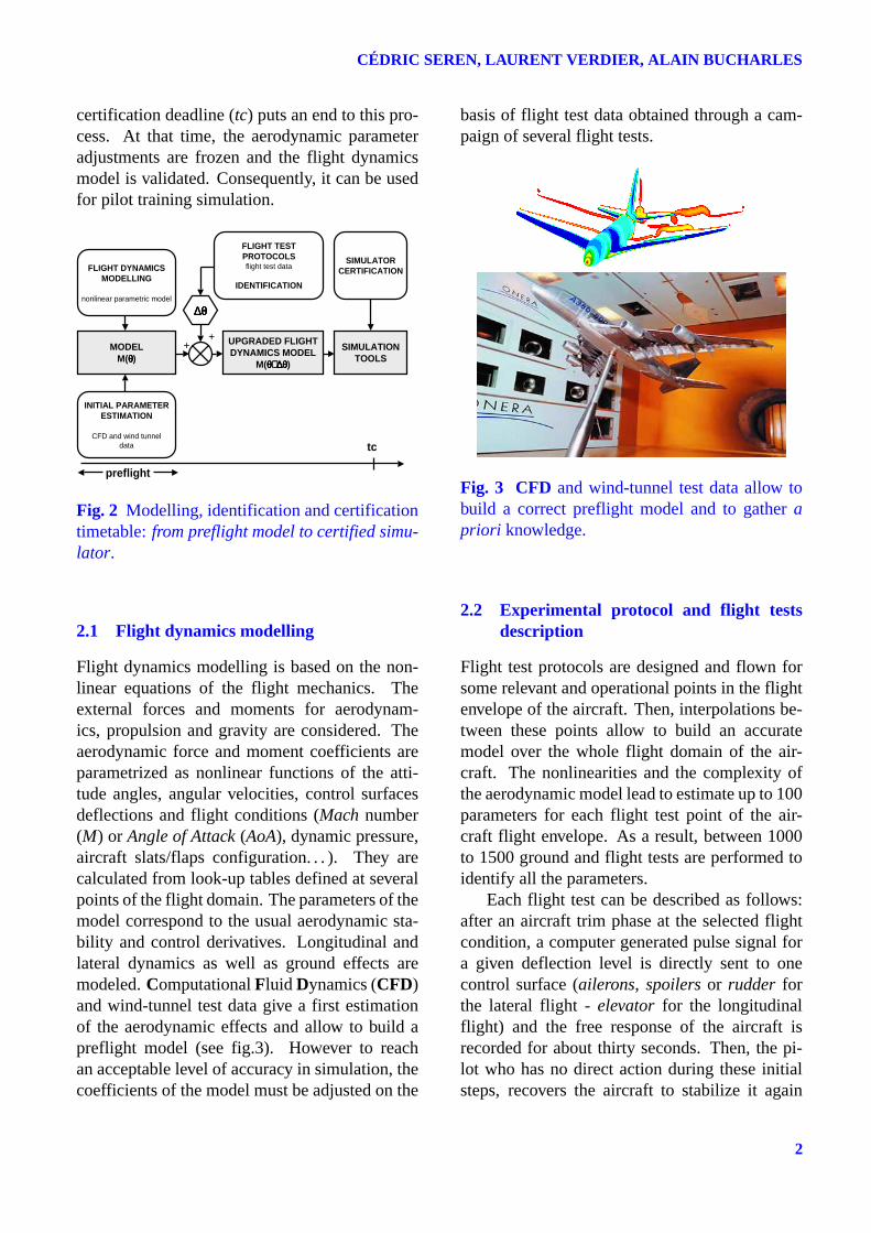
The aircraft identification process follows aschedule whose milestones are given by figure 2.Several phases can be distinguished in thistimetable. The process starts by building apreflight model of the flight dynamics. Then,flight test protocols are performed on the real air-craft and the aerodynamic model is adjusted onthe basis of the collected flight data. The type
1
CÉDRIC SEREN, LAURENT VERDIER, ALAIN BUCHARLES
certification deadline (tc) puts an end to this pro-cess. At that time, the aerodynamic parameteradjustments are frozen and the flight dynamicsmodel is validated. Consequently, it can be usedfor pilot training simulation.
MODELM(θθθθ)
UPGRADED FLIGHTDYNAMICS MODEL
M(θ+∆θθ+∆θθ+∆θθ+∆θ)
SIMULATIONTOOLS
INITIAL PARAMETERESTIMATION
CFD and wind tunneldata
FLIGHT DYNAMICSMODELLING
nonlinear parametric model
∆θ∆θ∆θ∆θ
FLIGHT TESTPROTOCOLSflight test data
IDENTIFICATION
SIMULATORCERTIFICATION
++
tc
preflight
Fig. 2 Modelling, identification and certificationtimetable: from preflight model to certified simu-lator.
2.1 Flight dynamics modelling
Flight dynamics modelling is based on the non-linear equations of the flight mechanics. Theexternal forces and moments for aerodynam-ics, propulsion and gravity are considered. Theaerodynamic force and moment coefficients areparametrized as nonlinear functions of the atti-tude angles, angular velocities, control surfacesdeflections and flight conditions (Mach number(M) or Angle of Attack (AoA), dynamic pressure,aircraft slats/flaps configuration. . . ). They arecalculated from look-up tables defined at severalpoints of the flight domain. The parameters of themodel correspond to the usual aerodynamic sta-bility and control derivatives. Longitudinal andlateral dynamics as well as ground effects aremodeled. Computational Fluid Dynamics (CFD)and wind-tunnel test data give a first estimationof the aerodynamic effects and allow to build apreflight model (see fig.3). However to reachan acceptable level of accuracy in simulation, thecoefficients of the model must be adjusted on the
basis of flight test data obtained through a cam-paign of several flight tests.
Fig. 3 CFD and wind-tunnel test data allow tobuild a correct preflight model and to gather apriori knowledge.
2.2 Experimental protocol and flight testsdescription
Flight test protocols are designed and flown forsome relevant and operational points in the flightenvelope of the aircraft. Then, interpolations be-tween these points allow to build an accuratemodel over the whole flight domain of the air-craft. The nonlinearities and the complexity ofthe aerodynamic model lead to estimate up to 100parameters for each flight test point of the air-craft flight envelope. As a result, between 1000to 1500 ground and flight tests are performed toidentify all the parameters.
Each flight test can be described as follows:after an aircraft trim phase at the selected flightcondition, a computer generated pulse signal fora given deflection level is directly sent to onecontrol surface (ailerons, spoilers or rudder forthe lateral flight - elevator for the longitudinalflight) and the free response of the aircraft isrecorded for about thirty seconds. Then, the pi-lot who has no direct action during these initialsteps, recovers the aircraft to stabilize it again
2

On Flight Dynamics Model Identification and Optimal Flight Test Protocol Design
at the flight test point. Several deflection ampli-tudes are done to identify the nonlinear effective-nesses. After that, the pilot stabilizes the aircraftat the next flight domain condition and the wholeprocedure is performed again.
In the case of the lateral flight, these tests aretypically:
• roll and yaw rate responses through inputsignals sent to ailerons, spoilers and rud-der;
• steady state sideslip. This kind of test al-lows to estimate accurately ratios betweenstability and control derivatives (see fig.5and 6);
• more piloted flight tests such as: dynamicengine failure, engine out trim and mini-mum aircraft control speed (maximum rud-der deflection) which allow to estimate par-ticular nonlinearities.
SPOILERS INPUT ROLL RATE RESPONSE
Fig. 4 Dutch Roll flight test through a spoilerspulse input.
They bring relevant information for theidentification of the aerodynamic parameters andare based on the experience of our specialists.The simplicity of the input signals in the cur-rent flight tests allows to keep the aircraft re-sponses readable by our experts. Natural modesof the aircraft such as dutch roll (see fig.4), spi-ral stability and roll response for the lateral flightand phugoïd and short period for the longitudi-nal flight are observed on the data and provide,
through the analyzis of the specialists, a firstqualitative idea of the adjustments required in themodel. However, combined with the complex-ity of the model, it can lead to design exhaustiveexperimental protocols. Consequently, the totalflight test time allocated to the identification pro-cess can be huge.
2.3 Identification methodology
Aircraft flight dynamics identification is carriedout according two methodologies based on dif-ferent principles:
• the first one determines the aerodynamicforces and moments applied to the aircraftand uses an equation error approach to an-alyze the steady state sideslip flight tests.This allows to estimate some nonlineari-ties;
• the second one deals with the applicationof the output error approach (OEA) and al-lows to estimate more precisely the aerody-namic parameters from all the maneuverssent to the aircraft.
The identification process is based on the in-formation available in the specific steady statesideslip experiments (see fig.5 and 6). Somestates of the aircraft are piloted to be kept nearzero during this type of flight test while the air-craft is stabilized at a given sideslip amplitude.Several sideslip levels are swept. This allows todetermine the dependence of some coefficientstowards the sideslip effect. By a comparison withthe real aircraft, some relations can be establishedand ratios are estimated between particular stateand control derivatives. The sideslip nonlineari-ties can be identified as well as nonlinear effec-tivenesses (see fig.6).
Parameter estimation is then completed bythe application of the Output Error Approach(OEA) (see fig.7) to the data collected during theflight test campaign. It allows to estimate moreprecisely the corrections of the aerodynamic pa-rameters to be applied. State derivatives and
3

CÉDRIC SEREN, LAURENT VERDIER, ALAIN BUCHARLES
Fig. 5 Steady state sideslip data processing. Se-lection of the stabilized sideslip phases.
ny = f(ββββ)roll control = f(ββββ)
rudder effectiveness = f(ββββ)
Fig. 6 Analyzis of the stabilized points. Sideslipdependency of some variables.
deflection effects as well as particular nonlin-earities are estimated. They allow to refine theglobal and stationary effects in the flight dynam-ics model.
As the experts have a preflight model ofhigh quality at their disposal, this identificationmethodology which is based on the minimiza-tion of an output error criterion computed fromthe measurements and the simulated outputs, ap-pears well adapted for the nonlinear estimation of
AIRCRAFT
NOISE w(t)
+
+
MEASURES
SIMULATED OUTPUTS
+
-CRITERION J(θθθθ)
MINIMIZATION
ALGORITHM
Gauss-Newton
FLIGHTTEST
INPUTS
CFD&
WIND TUNNELDATA
PARAMETRIC MODEL
M(θθθθ)
Fig. 7 The OEA methodology
the aerodynamic parameters. It reproduces with agood quality the global aircraft behaviour in sim-ulation while it is more difficult and it requiresmore time of analyzis to distribute precisely theadjustments between all the aerodynamic effects.Thus, some difficulties subsist: for example, theprocessing of the information through test datadoes not allow to separate some aerodynamic ef-fects accurately. Single input excitations gener-ally provide a good estimation of the control sur-face effectivenesses while it is more difficult tosort the aerodynamic effects corresponding to thestate variables (sideslip, roll and yaw rates for thelateral flight). A higher level of accuracy is pos-sible by modifying the identification process andespecially the flight test protocol.
3 New requirements
Even if flight dynamics modelling andidentification methodology have reached ahigh level of maturity at AIRBUS, the accuracyimprovement of the estimated parameters andthe reduction of the total flight test time arepermanent concerns. The schedule for aircraftsimulator certification becomes shorter andshorter (see fig.2) and the constraint on thereliability of the flight dynamics model forsimulation increases. Combined with a reductionof the flight test campaign costs, these factorsraise a need for optimizing the flight test proto-cols. Moreover, the application of new controllaw strategies (new designs, management ofstructural loads and passenger comfort, handling
4

On Flight Dynamics Model Identification and Optimal Flight Test Protocol Design
qualities performance. . . ) involves the designof more accurate flight dynamics models. Con-sequently, a thought about an optimization ofthe current experimental protocols dedicated toflight dynamics model identification has started.It aims at improving the accuracy of the modelin simulation while reducing the flight testcampaign costs.
As the aerodynamic parameter estimationprocess is dependent on the quality of the inputssent to the aircraft, a new optimization method-ology has been developed in order to designmore informative flight test protocols. It uses theprinciples of the Genetic Algorithms (GA) opti-mization technique. It is capable of generatingthrough an evolutive process an optimal set ofseveral input signals constituting a flight test pro-tocol.
4 Experimental protocol optimization
4.1 Problem formulation
The state of the art in the field of OptimalInput Design (OID) points out as a referencethe methodology developed by E. A. Morelliand V. Klein ([2] and [5]) which applies theprinciples of Dynamic Programming (DP). Thismethod builds dynamically an optimal input to-wards a mathematical criterion. Due to some lim-itations of the DP optimization technique (dis-cretization, CPU time. . . ), we have developed anew algorithm which applies the principles of theGenetic Algorithms (GA) optimization techniquefor solving OID problems. It is able to solve alarge panel of optimization problems:
• Single Flight Test with Single Input(SFTSI);
• Multiple Flight Tests with Single Input(MFTSI);
• Single Flight Test with Multiple Inputs(SFTMI);
• Multiple Flight Tests with Multiple Inputs(MFTMI).
The MFTSI framework corresponds to theclosest formulation for optimizing the currentflight test protocols. This optimization method-ology builds an optimal set of n (n ≥ 1) inputsignal(s) towards an optimization criterion whichis significant of the global accuracy of the esti-mation. The most common criteria used for op-timization are based on the fisher’s informationmatrix F:
• trF: represents the amount of informationavailable through the set of flight tests butdoes not take into account the possible cor-relations between the effects;
• log(detF): is indicative of the global sen-sitivities collected for a given set of flighttests. Inputs which maximize this scalarnorm are called D-optimal;
• trF−1: is equal to the sum of the variancesof the parameter estimation errors. F−1 isknown as the dispersion matrix. The inputswhich minimize this criterion are called A-optimal;
• λmax of F−1: is equal to the maximum ra-dius of the uncertainty ellipsoïd.
We have chosen to minimize the trace of thedispersion matrix. The optimization is subjectto some constraints: the designed input signalsmust be feasible and their use in flight test condi-tion must respect safety constraints. Moreover, asthe identification is made for one flight conditionof the aircraft envelope1, input and output limita-tions must be introduced to avoid any departureof the aircraft from this point. The candidate in-put signals chosen for each flight test are mul-tistep signals whose amplitudes can be chosenamong the break points of the look-up tables. An-other input forms are possible (ramp, sinus. . . ).By combining several deflection amplitudes in an
1so that the experimental conditions can be consideredstationary over the whole flight tests composing the exper-imental protocol
5

CÉDRIC SEREN, LAURENT VERDIER, ALAIN BUCHARLES
only single flight test a significant gain in the to-tal flight test time can be made thanks to this op-timization algorithm.
For improving the overall level of accuracy,research works have shown that it was valuableto add closed-loop flight tests in order to sepa-rate strongly correlated aerodynamic effects [7].In this case, only a reference input signal sent toa control law has to be optimized. An alternativesolution will consist in sending a set of correlatedinputs to the dynamic system so that system out-puts will be decorrelated. These two approacheshave their own advantages:
• the synthesis of correlated inputs in open-loop in a OID framework can be highlyparametrized and offers numerous degreesof freedom;
• the closed-loop framework is potentiallymore robust towards model uncertainties;
• the flight test constraints of the optimiza-tion problem can be managed more eas-ily in the closed-loop framework becausesome states of the aircraft are commandedby a control law;
• existing control laws can be used at first torealize the closed-loop solution, especiallythe decoupling control laws.
and their own drawbacks:
• constraints may be difficult to manage inthe open-loop case;
• fewer degrees of freedom are avalaible forthe closed-loop optimization;
• the closed-loop framework is a new op-timization problem in which little experi-ence has been accumulated.
Using closed-loop experiments together withmore classical open-loop tests appears as anew idea in the identification domain whichbrings new perspectives for the field of OptimalExperiment Design (OED). The optimization
Initialization
1st random population of N individuals
Individuals encoding
Individuals evaluation: fitness calculation
Individualsselection
Individuals crossing-over: offspring
generation
Individuals mutations
Offspring evaluation: fitness calculation
ElitismStopping criterionsatisfied ?
Best individual = Optimum
NO
YES
Fig. 8 Principle of the GA optimization technique.
tool developed to tackle OID problems is able tooptimize flight test protocols composed of open-loop and closed-loop experiments. The latter fea-ture is essential to optimize a global informationin a MFTSI framework which mixes open-loopinput signals and closed-loop reference inputs.Thus, optimization results and conclusions canbe made in order to analyze the relevance of theclosed-loop information contains in experimentalprotocols.
4.2 Basic principles of the GA optimizationmethodology
As the optimization problem formulation isglobal and complex (with a high combinatory),the use of a global and evolutionary optimizationtechnique such as GA appears well adapted. Theresulting algorithm follows the usual steps of theGA technique described in the theory [1]. Thebasic principle of such an iterative optimizationmethodology is summarized by the figure 8.
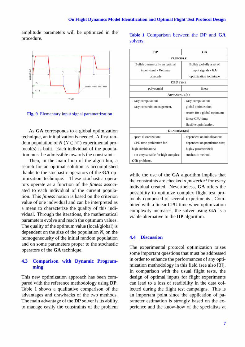
An important point in our optimization al-gorithm concerns the choice of a relevantparametrization for handling in an easy way theelementary input signals through the iterations.Each elementary input signal can be completelydescribed by: the shape of a basic signal (in ourstudy, the steps); and by the coordinates of eachswitching instant in the two-dimension subspaceE = (time,amplitude) (see fig.9). The time and
6
On Flight Dynamics Model Identification and Optimal Flight Test Protocol Design
amplitude parameters will be optimized in theprocedure.
0
TIME
AM
PLI
TUD
E
SWITCHING INSTANT
ti ti+1
ai
ai+1
Fig. 9 Elementary input signal parametrization
As GA corresponds to a global optimizationtechnique, an initialization is needed. A first ran-dom population of N (N ∈ N
∗) experimental pro-tocol(s) is built. Each individual of the popula-tion must be admissible towards the constraints.
Then, in the main loop of the algorithm, asearch for an optimal solution is accomplishedthanks to the stochastic operators of the GA op-timization technique. These stochastic opera-tors operate as a function of the fitness associ-ated to each individual of the current popula-tion. This fitness notion is based on the criterionvalue of one individual and can be interpreted asa mean to characterize the quality of this indi-vidual. Through the iterations, the mathematicalparameters evolve and reach the optimum values.The quality of the optimum value (local/global) isdependent on the size of the population N, on thehomogeneousity of the initial random populationand on some parameters proper to the stochasticoperators of the GA technique.
4.3 Comparison with Dynamic Program-ming
This new optimization approach has been com-pared with the reference methodology using DP.Table 1 shows a qualitative comparison of theadvantages and drawbacks of the two methods.The main advantage of the DP solver is its abilityto manage easily the constraints of the problem
Table 1 Comparison between the DP and GAsolvers.
DP GA
PRINCIPLE
Builds dynamically an optimal Builds globally a set of
input signal - Bellman input signals - GA
principle optimization technique
CPU TIME
polynomial linear
ADVANTAGE(S)
- easy computation; - easy computation;
- easy constraint management. - global optimization;
- search for a global optimum;
- linear CPU time;
- flexible optimization.
DRAWBACK(S)
- space discretization; - dependent on initialization;
- CPU time prohibitive for - dependent on population size;
high combinatory; - highly parametrized;
- not very suitable for high complex - stochastic method.
OID problems.
while the use of the GA algorithm implies thatthe constraints are checked a posteriori for everyindividual created. Nevertheless, GA offers thepossibility to optimize complex flight test pro-tocols composed of several experiments. Com-bined with a linear CPU time when optimizationcomplexity increases, the solver using GA is aviable alternative to the DP algorithm.
4.4 Discussion
The experimental protocol optimization raisessome important questions that must be addressedin order to enhance the performances of any opti-mization methodology in this field (see also [3]).In comparison with the usual flight tests, thedesign of optimal inputs for flight experimentscan lead to a loss of readibility in the data col-lected during the flight test campaigns. This isan important point since the application of pa-rameter estimation is strongly based on the ex-perience and the know-how of the specialists at
7

CÉDRIC SEREN, LAURENT VERDIER, ALAIN BUCHARLES
AIRBUS. However, the use of softwares whichapply some theoretical estimation methodologiesjustifies such an optimization. Consequently,the experimental protocols tends to become in ashort-range forecast a mix of usual and optimizedtests. The use of a global optimization techniquesuch as GA for solving OID problems raises theissue of the interest to have a global optimum atour disposal for parameter estimation. Since weknow that the search for a global optimum canbe time consuming, attention must be paid to thefact that suboptimal solutions exist and could beused without losing the overall performances ofthe parameter estimation in terms of accuracy,flight test time and practical implementation ofthe inputs. Actually, the choice of a global op-timization technique is mainly justified by theability that global methodologies have to tacklehigh dimension optimization problems. Becauseof the global characteristic of the experimentalprotocol optimization formulation, this latter fea-ture is a key factor for the choice of a mathe-matical optimization method. Besides, as anyexperimental protocol optimization is made overa preflight model, the optimal set of inputs de-signed must be robust with respect to potentialuncertainties and undermodellings. Indeed, if theflight test time performance can be guaranteedthrough the mathematical formulation of the op-timization problem, the performances in terms ofaccuracy can only be obtained in flight under thehypothesis that the preflight model correspondsexactly to the real aircraft that is practically neverthe case. This last point constitutes the mainlimitation and the paradox of the optimal exper-iment and input design fields. Some interestingresearch works by E. Walter and L. Pronzato [4]dealing with robust optimization can potentiallyhelp us in our application of optimal experimentand input design for aircraft parameter estimationand can provide a theoretical support to enhancethe performances of our optimization algorithm.
5 Results
The case of the lateral flight is considered. Thestandard protocol is composed of eleven flight
tests with a pulse input. 34 parameters are to beestimated:
• sideslip, roll and yaw rates effects over thethree aircraft axis for the lateral flight (9parameters);
• 5 deflection level effects for ailerons andspoilers (22 parameters);
• global rudder effect (3 parameters).
In this example, the objective of the opti-mized protocol is to reach an equivalent level ofestimation accuracy with a reduced number offlight tests and a reduced flight test time. Threeoptimized flight tests were selected:
• optimized ailerons input signal;
• optimized spoilers input signal;
• optimized rudder input signal.
The numerical results of this optimization aregiven in table 2. They show that a significant gainin the flight test time can be made by optimizingthe input signals of a current protocol design andby concatening pulses with different amplitudesfor a given control surface into an only single op-timized input sequence. The number of experi-ments is divided by 4 while the level of accuracyis only 22 percent over its initial value.
Table 2 Comparison of standard and optimizedfight test protocols.
PROTOCOL CURRENT OPTIMIZED
NUMBER OF EXP. 11 3
CRITERION 0.0718 0.0876 (+22%)
FLIGHT TEST TIME (FTT) 352 secs 96 secs (−73%)
FTT PER EXPERIMENT 32 secs 32 secs
As the input signals are optimized over thetotal flight test time of each flight test, we canarbitrarily add for these optimized experimentsa free response of the aircraft since the gain inthe global flight test time is significant (−73%)
8

On Flight Dynamics Model Identification and Optimal Flight Test Protocol Design
0 10 20 30 40 50 600.02
0.03
0.04
0.05
0.06
0.07
0.08
0.09
Aircraft free response (sec.)
Cri
teri
on
(wu
)
0 10 20 30 40 50 6050
100
150
200
250
300
350
400
Aircraft free response (sec.)
Pro
toco
lfl
ight
test
tim
e(s
ec.)
Current Design ProtocolOptimized Protocol
Current Design ProtocolOptimized Protocol
Fig. 10 Potential gain in flight test time throughoptimized input signals. Effect of the record ofan aircraft free response in the optimized data.
and allows us to proceed this way. Thus, as aquantity of information is added through free air-craft responses, we can look for a gain in thelevel of accuracy provided by the optimized pro-tocol design. Figure 10 shows the effects bothon the accuracy of parameter estimation and thetotal flight test time of an additive free aircraftresponse. A significant gain in estimation ac-curacy can be made without penalizing the totalflight test time since optimized input signals aredesigned. The reference values for the currentprotocol design are given by the red lines.
OED and OID results are now entered in aphase of validation in flight. A flight test cam-paign has been flown in order to validate the the-oretical results obtained in simulation. The aimis to demonstrate that this kind of new input sig-nals is able to provide at least the same levelof accuracy for parameter estimation as in theusual flight test protocols while it is able to re-duce significantly the total flight test time. Fig-ures 11 and 12 show two examples of optimizedinput signal sent to one control surface of a largetransport civil aircraft.
6 Conclusion
The optimization methodology applying GA pre-sented in this paper has provided promising the-oretical results. A better quality of the estimationand a reduction of the total flight test time canbe obtained. Similarly, the idea to mix closed-loop information with usual open-loop informa-tion seems interesting to separate some aerody-namic effects. A first flight campaign includingboth optimized and closed-loop flight tests hasbeen performed on a large transport civil aircraftto evaluate this method. In the future, we canexpect that optimized tests realized in open orclosed-loop will constitute an informative com-plement of the standard flight tests used today toidentify the flight dynamics models.
References
[1] Holland, J. H. Adaptation in natural and artificialsystems. University of Michigan press, 1975.
[2] Morelli, E. A. Practical input optimizationfor aircraft parameter estimation experiments.PhD.Report, George Washington University JI-AFS, DC, 1993.
[3] Breeman, J. H., Mulder, J. A. and Sridhar, J. K.Identification of dynamic systems - applicationsto aircraft - part 2: nonlinear analysis andmanœuvre design. AGARD-AG-300, Vol.3 Part2, 1994.
[4] Walter, E. and Pronzato, L. Identification de mod-èles paramétriques à partir de données expéri-mentales. Masson, 1994.
[5] Morelli, E. A. and Klein, V. Application of sys-tem identification to aircraft at NASA Langley re-search center. Journal of Aircraft, 42, pp.12-25,2005.
[6] Seren, C., Bommier, F., Bucharles, A., Verdier, L.and Alazard, D. Flight test protocol optimiza-tion using genetic algorithms. 14th IFAC Sympo-sium on System Identification Proceedings, 29-31 March 2006, Newcastle, Australia.
[7] Seren, C., Bommier, F., Bucharles, A., Verdier, L.and Alazard, D. Optimal experiment and inputdesign for flight test protocol optimization. AIAAAtmospheric Flight Mechanics Conference andExhibit Proceedings, 21-24 August 2006.
9

CÉDRIC SEREN, LAURENT VERDIER, ALAIN BUCHARLES
LEFT AILERONS RIGHT AILERONS
ROLL RATE SIDESLIP
Fig. 11 Example of optimized ailerons flight test.
LEFT SPOILERS RIGHT SPOILERS
ROLL RATE SIDESLIP
Fig. 12 Example of optimized spoilers flight test.
10